US7327321B2 - Electromagnetic radiation assembly - Google Patents
Electromagnetic radiation assemblyDownload PDFInfo
- Publication number
- US7327321B2 US7327321B2US11/168,118US16811805AUS7327321B2US 7327321 B2US7327321 B2US 7327321B2US 16811805 AUS16811805 AUS 16811805AUS 7327321 B2US7327321 B2US 7327321B2
- Authority
- US
- United States
- Prior art keywords
- electromagnetic radiation
- reflector
- substrate
- assembly
- semitransparent
- Prior art date
- Legal status (The legal status is an assumption and is not a legal conclusion. Google has not performed a legal analysis and makes no representation as to the accuracy of the status listed.)
- Expired - Fee Related, expires
Links
- 230000005670electromagnetic radiationEffects0.000titleclaimsabstractdescription192
- 239000000758substrateSubstances0.000claimsdescription101
- 238000005286illuminationMethods0.000description21
- 238000000576coating methodMethods0.000description16
- 230000000712assemblyEffects0.000description13
- 238000000429assemblyMethods0.000description13
- 230000011664signalingEffects0.000description12
- 239000011248coating agentSubstances0.000description10
- 230000002829reductive effectEffects0.000description5
- 230000000873masking effectEffects0.000description4
- 230000000007visual effectEffects0.000description4
- 230000008859changeEffects0.000description3
- 230000000694effectsEffects0.000description3
- 238000012986modificationMethods0.000description3
- 230000004048modificationEffects0.000description3
- 230000002093peripheral effectEffects0.000description3
- 230000008901benefitEffects0.000description2
- 230000007613environmental effectEffects0.000description2
- 238000000034methodMethods0.000description2
- 230000036961partial effectEffects0.000description2
- VYZAMTAEIAYCRO-UHFFFAOYSA-NChromiumChemical compound[Cr]VYZAMTAEIAYCRO-UHFFFAOYSA-N0.000description1
- 229910052804chromiumInorganic materials0.000description1
- 239000011651chromiumSubstances0.000description1
- 238000010276constructionMethods0.000description1
- 230000003247decreasing effectEffects0.000description1
- 230000005611electricityEffects0.000description1
- 230000006870functionEffects0.000description1
- 238000001746injection mouldingMethods0.000description1
- 230000037361pathwayEffects0.000description1
- 230000000737periodic effectEffects0.000description1
- 230000002441reversible effectEffects0.000description1
- 239000000243solutionSubstances0.000description1
- 239000012899standard injectionSubstances0.000description1
- 239000000126substanceSubstances0.000description1
Images


Classifications
- B—PERFORMING OPERATIONS; TRANSPORTING
- B60—VEHICLES IN GENERAL
- B60R—VEHICLES, VEHICLE FITTINGS, OR VEHICLE PARTS, NOT OTHERWISE PROVIDED FOR
- B60R1/00—Optical viewing arrangements; Real-time viewing arrangements for drivers or passengers using optical image capturing systems, e.g. cameras or video systems specially adapted for use in or on vehicles
- B60R1/12—Mirror assemblies combined with other articles, e.g. clocks
- B—PERFORMING OPERATIONS; TRANSPORTING
- B60—VEHICLES IN GENERAL
- B60Q—ARRANGEMENT OF SIGNALLING OR LIGHTING DEVICES, THE MOUNTING OR SUPPORTING THEREOF OR CIRCUITS THEREFOR, FOR VEHICLES IN GENERAL
- B60Q1/00—Arrangement of optical signalling or lighting devices, the mounting or supporting thereof or circuits therefor
- B60Q1/26—Arrangement of optical signalling or lighting devices, the mounting or supporting thereof or circuits therefor the devices being primarily intended to indicate the vehicle, or parts thereof, or to give signals, to other traffic
- B60Q1/2661—Arrangement of optical signalling or lighting devices, the mounting or supporting thereof or circuits therefor the devices being primarily intended to indicate the vehicle, or parts thereof, or to give signals, to other traffic mounted on parts having other functions
- B60Q1/2665—Arrangement of optical signalling or lighting devices, the mounting or supporting thereof or circuits therefor the devices being primarily intended to indicate the vehicle, or parts thereof, or to give signals, to other traffic mounted on parts having other functions on rear-view mirrors
- B—PERFORMING OPERATIONS; TRANSPORTING
- B60—VEHICLES IN GENERAL
- B60R—VEHICLES, VEHICLE FITTINGS, OR VEHICLE PARTS, NOT OTHERWISE PROVIDED FOR
- B60R1/00—Optical viewing arrangements; Real-time viewing arrangements for drivers or passengers using optical image capturing systems, e.g. cameras or video systems specially adapted for use in or on vehicles
- B60R1/12—Mirror assemblies combined with other articles, e.g. clocks
- B60R2001/1284—Mirror assemblies combined with other articles, e.g. clocks with communication systems other than radio-receivers, e.g. keyless entry systems, navigation systems; with anti-collision systems
Definitions
- the present inventionrelates to an electromagnetic radiation assembly, and more specifically to an assembly which may operate as a combined warning lamp and rearview mirror and which is operable to illuminate regions adjacent to the overland vehicle and which assists in the safe operation of the overland vehicle as by signaling adjacent vehicles of the intention of the operator to change the direction of the overland vehicle; to assist the operator in entering or departing the vehicle during reduced periods of visibility; and further to provide information of interest, to the operator of the overland vehicle.
- auxiliary signaling assemblieswhich have been employed for various purposes on overland vehicles of assorted designs.
- these auxiliary signaling assemblieshave utilized assorted semitransparent mirrors including dichroic and electrochromic type mirrors as well as neutrally chromatic mirrors which have been modified, in various fashions, so as to be rendered semitransparent.
- warning lamps or indicatorsmay be located so as to provide periodic information to the operator regarding the operational condition of the overland vehicle, or other conditions such as ambient environmental conditions which could effect the safe operation of the overland vehicle.
- warning lamps and indicatorshave provided such information as tire pressure, temperature, and proximity to fixed objects which may be impacted when the vehicle is being operated in reverse, for example.
- one aspect of the present inventionrelates to an electromagnetic radiation assembly which includes a reflector having distinct first and second surfaces, and first and second portions; a first electromagnetic radiation emitter positioned adjacent to the first surface, and which, when energized, emits visibly discernible electromagnetic radiation which is reflected by the first portion of the reflector so as to be visible at locations forward of the first surface; and a second electromagnetic radiation emitter positioned adjacent to the second surface of the reflector, and which, when energized, emits visibly discernible electromagnetic radiation which is reflected by the second portion of the reflector so as to be visible at locations forward of the first surface.
- a electromagnetic radiation assemblywhich includes a first supporting substrate having distinct first and second surfaces, and which defines, at least in part, an aperture which permits visibly discernible electromagnetic radiation to pass therethrough; a first electromagnetic radiation emitter positioned on the second surface of the first supporting substrate, and near the aperture; a reflector having a first and second portion, and wherein the first portion is oriented in reflecting relation relative to the first electromagnetic radiation emitter, and which reflects, at least in part, electromagnetic radiation which is emitted by first electromagnetic radiation emitter through the aperture such that the emitted electromagnetic radiation may be detected at locations forward of the first surface of the first supporting substrate; a second electromagnetic radiation emitter positioned in spaced relation relative to the first supporting substrate, and wherein the reflector is positioned therebetween the second electromagnetic radiation emitter, and the first supporting substrate, and wherein the second portion of the reflector reflects, at least in part, electromagnetic radiation which is emitted by the second electromagnetic radiation emitter through the aperture such that the emitted electromagnetic radiation may be detected at locations forward of the first electromagnetic radiation assembly
- Still another aspect of the present inventionrelates to an electromagnetic radiation assembly which includes a first supporting substrate having first and second surfaces, and which defines, at least in part, an aperture which passes visibly discernible light therethrough; a first electromagnetic radiation emitter borne by the second surface, and which, when energized, emits visibly discernible light; a reflector having a first portion which defines, at least in part, a reflector pocket which is disposed in substantially covering, eccentric reflecting relation relative to the first electromagnetic radiation emitter, and a second portion, and wherein the visibly discernible light emitted by the first electromagnetic radiation emitter is reflected, at least in part, by the reflector pocket, and subsequently passes through the aperture of the first supporting substrate such that it can be seen from a location forward of the first surface of the first supporting substrate; a second substrate positioned in spaced relation relative to the reflector, and wherein the reflector is positioned therebetween the first and second supporting substrates; and a second electromagnetic radiation emitter borne by the second substrate, and which, when energized, emits vis
- an electromagnetic radiation assemblywhich includes a first supporting substrate having first and second surfaces, and which further has a region through which an electromagnetic radiation signal may pass; a first plurality of electromagnetic radiation emitters borne by the second surface, and positioned adjacent to the region through which an electromagnetic radiation signal may pass, and wherein the first plurality of electromagnetic radiation emitters, when energized, emits electromagnetic radiation which forms a first electromagnetic radiation signal; a reflector having a plurality of reflector pockets which are individually positioned in covering, eccentric reflecting relation relative to each of the first plurality of electromagnetic radiation emitters, and wherein the reflector further includes a region thorough which a second electromagnetic radiation signal may pass, and wherein the first electromagnetic radiation signal generated by the first plurality of electromagnetic radiation emitters is reflected by the respective reflector pockets in a direction so as to substantially pass through the region in the first supporting substrate which passes the first electromagnetic radiation signal; a second supporting substrate having first and second surfaces, and which is positioned in spaced relation relative to the reflector, and wherein the reflector
- FIG. 1is a greatly simplified, perspective exploded view of one form of the electromagnetic radiation assembly of the present invention.
- FIG. 2is a partial, plan view of the electromagnetic radiation assembly of the present invention with a semitransparent substrate thereof removed to show the structure thereunder.
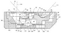
- FIG. 3is a transverse, vertical, sectional view of the electromagnetic radiation assembly of the present invention and which is taken from a position along line 3 - 3 of FIG. 2 .
- FIG. 4is a longitudinal, vertical, sectional view of the electromagnetic radiation assembly of the present invention and which is taken from a position along line 4 - 4 of FIG. 2 .
- FIG. 5is a perspective transverse, vertical, sectional view of the electromagnetic radiation assembly of the present invention and which is again taken from a position along line 3 - 3 of FIG. 2 .
- FIG. 6is a partial, plan view of a second form of the electromagnetic radiation assembly of the present invention.
- FIG. 7is a greatly simplified, perspective, exploded view of the second form of the electromagnetic radiation assembly of the present invention.
- FIGS. 8A , B and Care greatly simplified, schematic views of the pattern of visibly discernable electromagnetic radiation emitted by the first and second forms of the invention during their various modes of operation.
- the electromagnetic radiation assembly of the present inventionis generally indicated by the numeral 10 in FIG. 1 and following.
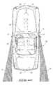
- the electromagnetic radiation assembly 10 of the present inventionand which is shown and described herein, is discussed as it would be configured if it were installed on an overland vehicle 11 of conventional design and which is best seen by reference to FIG. 8 .
- the electromagnetic radiation assembly (hereinafter referred to as assembly 10 ) of the present inventionoperates as a combination rearview mirror, and visual signaling device, and wherein the visual signaling device provides a visual signal or pattern of illumination which is capable of being perceived from various locations which are located in assorted different directions which are laterally outwardly, inwardly, and rearwardly of the overland vehicle, when the invention is operating in its several operational modes.
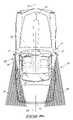
- the present assembly 10is operable to generate visibly discernable electromagnetic radiation which can be seen as illustrated in FIG. 8A at locations laterally outwardly relative to the overland vehicle 11 ; laterally inwardly relative to the overland vehicle as seen in FIG. 8B ; and rearwardly and downwardly as seen in FIG. 8C .
- Other emission patternsare also possible.
- the present invention 10is mounted on an overland vehicle 11 of conventional design.
- the overland vehicle 11has a front or forward portion 12 , and a rearward portion 13 .
- the overland vehicle 11further has a passenger compartment 14 where an operator of the overland vehicle is seated.
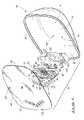
- the overland vehicleincludes exterior locations 21 for a pair of exterior rearview mirrors which incorporate the present invention and which are best understood by a study of FIGS. 1 and 7 , respectively.
- the overland vehicle 11also has a hand operated directional signaling switch; and foot brake (not shown), and which when utilized, provides an electrical signal which may alert drivers of other vehicles in the immediate vicinity that the overland vehicle 11 is about to change directions, turn, change lanes, etc. Yet further, other signals or warning icons may also be provided, and which can be viewed from the overland vehicle and which will alert the operator of various conditions existing on the overland vehicle, or outside ambient environmental conditions which may effect the safe operation of the overland vehicle.
- the overland vehicle 11may be equipped with a radio frequency receiver 22 and which receives an RF signal which is transmitted from a key fob held by the operator of the overland vehicle (not shown). This RF signal, once received, is effective to unlock the various doors of the overland vehicle and further is useful in actuating the operation of the assembly 10 in one of its several modes of operation, as will be discussed below.
- an operator of an overland vehicle 11 when positioned in the operator's position 20has a field of view which extends approximately 180° from the operator's position towards the forward portion 12 of the vehicle.
- the operatormay, by looking along given lines of sight, view rearwardly of the vehicle along the driver's side, passenger side, and substantially along a longitudinal axis 23 of the overland vehicle 11 when the operator views an interior rearview mirror, which is not shown. As depicted in FIGS.
- the assembly 10 of the present inventionwhen energized, provides a plurality of illumination zones which are generally indicated by the numeral 30 .
- These illumination zonesinclude a first illumination zone 31 ( FIG. 8A ) which provides visibly discernable electromagnetic radiation which is visible at positions which are laterally, outwardly relative to the intended direction of travel of the overland vehicle 11 .
- This first illumination zoneis designed to direct visibly discernable electromagnetic radiation at vehicles traveling rearwardly and in adjacent lanes relative to the overland vehicle 11 when the apparatus is operating in a first mode.
- the second illumination zone 32provides visibly discernable electromagnetic radiation which is oriented substantially laterally, inwardly relative to the direction of movement of the overland vehicle, and which can be perceived by the operator of same when the apparatus is operating in a second mode.
- this second illumination zoneis employed to transmit information of interest to the operator of the overland vehicle 11 regarding the operational conditions of the overland vehicle 11 as well as other information which may be of interest in the safe operation of the overland vehicle 11 .
- the assembly 10when energized, provides a third illumination zone 33 which is oriented substantially laterally inwardly, and downwardly towards the face of the earth when the apparatus is operating in a third mode.
- the third illumination zoneis utilized typically for purposes of illuminating the side and region adjacent to the overland vehicle during periods of reduced visibility in order for an operator to safely enter or exit the overland vehicle.
- the first form of the assembly 10 of the present inventionis incorporated into a mirror housing which is generally indicated by the numeral 40 , and which is typically mounted at the mirror locations 21 on the exterior surface of the overland vehicle 11 .
- the mirror housing or enclosurehas a rear wall 41 , and a sidewall 42 extends outwardly therefrom.
- the sidewall 42has a peripheral edge 43 and which defines an aperture 44 having given dimensions.
- the rear wall 41 , and sidewall 42further defines a cavity 45 which receives and encloses the assembly 10 , and other associated devices such as a movable bezel, which is not shown.
- the bezelmay also include a cavity which matingly receives, at least in part, the assembly 10 .
- the bezelmovably supports the assembly 10 within the housing 40 .
- the assembly 10can be positionally adjusted either manually, or remotely, by an actuator (not shown) to a given angular orientation relative to the various lines of sight utilized by the operator (not shown) of the overland vehicle 11 . This movement of the assembly provides a means by which the operator may adjust his given field of view rearwardly of the overland vehicle 11 .
- the assembly 10 of the present inventionincludes a semitransparent substrate which is generally indicated by the numeral 50 , and which has a front, first or outside facing surface 51 , and an opposite, second or rearwardly facing surface 52 .
- the semitransparent substrateis a semitransparent mirror which is selected from the group of semitransparent mirrors comprising substantially neutrally chromatic; dichroic; electrochromic and/or combinations thereof.
- the semitransparent substrate or mirror 50further is defined by a peripheral edge 53 , which substantially corresponds in shape and in size to the aperture 44 which is defined by the peripheral edge 43 of the housing 40 . When assembled, the semitransparent mirror or substrate 50 substantially occludes the aperture 44 .
- the semitransparent substrate or mirror 50 of the present inventionmay take on several forms. As seen in FIGS. 1 and 7 , the semitransparent substrate or mirror typically comprises a substantially transparent or translucent substrate which has a highly reflective coating applied thereto. As should be understood, the reflective coating may be applied, either, on the one hand, to the first or outside facing surface 51 , or in the alternative, and more typically to the opposite, second or rearwardly facing surface 52 .
- the highly reflective coatingmay comprise any number of different highly reflective or mirror like coatings or substances such as chromium and the like, and which may be applied or formed in a manner which provides a commercially acceptable reflective surface.
- the resulting reflectance of the semitransparent mirror or substrate 50should be generally, on average, greater than about 35%. However, in other commercial applications, increased or decreased reflectance may be acceptable depending upon the end use of the assembly 10 .
- the semitransparent substrate or mirror 50has a first, or primary region 61 , and through which a visibly discernable electromagnetic radiation signal may pass; and an adjacent secondary region 62 . While only two regions are shown and discussed herein, it is of course possible to have a plurality of secondary regions depending upon the end use of the assembly 10 . These secondary regions may be adjacent to each other, or may be spaced at a distance and positioned at various locations about the semitransparent substrate or mirror 50 . As a general matter, however, the first or primary region 61 passes a portion of the visibly discernable electromagnetic radiation directed at same while simultaneously reflecting a given percentage of the visibly discernable electromagnetic radiation or light which comes from the ambient environment.
- the secondary region 62is operable to reflect ambient visibly discernable electromagnetic radiation and is otherwise considered nominally opaque. Depending upon the reflective or other masking layers which are applied to the opposite, rearwardly facing surface 52 , the secondary region 62 may be considered completely opaque. As discussed above, the combined average reflectance of the overall surface area of the semitransparent substrate or mirror 50 , including both the primary and secondary regions, is typically greater than about 35% when the assembly 10 is being employed for automotive applications, as noted above. In other industrial applications, the average reflectance may be lower or higher depending upon the desired end use. As seen in the drawings, the secondary region 62 is substantially continuous and reflects for automotive applications greater than about 35% of the ambient, visible, electromagnetic radiation, and which strikes the first outside facing surface 51 thereof.
- the secondary region 62passes less than about 10% of the ambient visibly discernable electromagnetic radiation.
- the first or primary region 61passes less than about 50% of visible electromagnetic radiation, and further reflects on average, less than about 40% of visible electromagnetic radiation.
- the semitransparent mirror 50includes a plurality of discrete apertures or regions 63 which may be formed in a given pattern, and in various densities in the reflective coating, and which facilitates the passage of visibly discernable electromagnetic radiation therethrough.
- the first or primary region 61may be formed by a number of different means including providing reduced thickness areas in the associated reflective coating which is provided. These reduced thickness areas in the mirror coating allow increased amounts of visibly discernable electromagnetic radiation to pass therethrough in relative comparison to the adjacent thicker areas in the secondary region 62 .
- the secondary regionas earlier discussed, may be coated with an opaque masking layer which substantially inhibits visibly discernable electromagnetic radiation from passing therethrough.
- the semitransparent mirror or substrate 50may have a dichroic mirror coating applied thereto.
- dichroic mirror coatingsof various types have been discussed in various U.S. Patents including U.S. Pat. Nos. 5,014,167 and 5,207,492 to name but a few. These dichroic mirror coatings are well known in the art, and further discussion regarding the nature and operation of these respective mirror coatings is not warranted.
- a substantially opaque masking layermay be applied over the secondary region 62 thereby making the secondary region substantially opaque and further permitting visible electromagnetic radiation to pass through the first or primary region 61 which is unmasked.
- the dichroic mirror coating which is applied to the semitransparent mirror or substrate 50may be selected to pass given bands of visibly discernable electromagnetic radiation or light in greater amounts than other bands of electromagnetic radiation thereby making the resulting semitransparent mirror or substrate 50 , on average, an acceptable reflector of visibly discernable electromagnetic radiation while simultaneously allowing increased amounts of visibly discernable electromagnetic radiation of the selected band of electromagnetic radiation to pass therethrough.
- another acceptable semitransparent mirror or substrate 50may include an electrochromic mirror of a construction similar to that seen in U.S. Pat. Nos. 6,257,746; and 6,512,624 the teachings of which are incorporated by reference herein. In view of these teachings, an electrochromic mirror may be useful in the practice of the present invention 10 as will be discussed in greater detail below. It is also possible to provide combined substrates 50 depending upon the end use of the assembly.
- the assembly 10 of the present inventionincludes a first substantially opaque substrate which is generally indicated by the numeral 70 .
- the first opaque substrateoperates, at least in part, as a circuit board in order to mount a plurality of electromagnetic radiation emitters which will be discussed below.
- the first substrate 70has a first surface 71 , which is typically juxtaposed relative to the second or rearwardly facing surface 52 of the semitransparent mirror 50 .
- the first substrate 70has a distinct second surface 72 .
- the first substrate 70defines, at least in part, one region 73 ( FIG. 1 ), although a plurality of regions may be defined, and through which visibly discernable electromagnetic radiation may pass.
- the region through which the electromagnetic radiation may pass 73may include a plurality of apertures 74 which are formed in the first substrate 70 and which extend therethrough.
- the apertures 74are positioned in a predetermined pattern in order to provide a resulting visual signal which may be viewed and understood by others at a distance relative to the overland vehicle 11 .
- the first substantially opaque substrate 70mounts on the second surface 72 thereof, a first plurality of electromagnetic radiation emitters 75 .
- the second surface 72also mounts electrically conductive passageways (not shown), and which electrically couple the respective electromagnetic radiation emitters 75 with a source of electrical power which is typically provided by the overland vehicle 11 .
- the first plurality of electromagnetic radiation emitters 75when energized, emit visibly discernable electromagnetic radiation which travels along a path which is generally indicated by the numeral 76 ( FIGS. 3 and 5 ), and which forms the first illumination zone 31 , as seen in FIG. 8A .
- the first plurality of electromagnetic radiation emittersare mounted on the second surface 72 of the first opaque substrate 70 , and near the region 73 which passes the visibly discernable electromagnetic radiation.
- the individual electromagnetic radiation emittersare typically associated with the individual apertures 74 which are formed in the first opaque substrate 70 . While the discussion above was directed to visibly discernable electromagnetic radiation, it is possible by means of the present invention to emit electromagnetic radiation which is not visible and which would be useful in other applications.
- the assembly 10 of the present inventionincludes a reflector which is generally indicated by the numeral 80 .
- the reflectorcan be fabricated by utilizing standard injection molding techniques, and post, reflective coating procedures. Alternatively, it may be pressure or vacuum formed from deformable sheets that have a highly reflective coating formed thereon.
- the reflector 80has a first surface 81 which is positioned near the second surface 72 of the first opaque substrate 70 ; and a distinct second surface 82 , as best seen by reference to FIG. 3 . In the arrangement as shown in FIG.
- the first opaque substrate 70matingly cooperates with the reflector 80 such that the reflector 80 is juxtaposed, at least in part, relative to the semitransparent mirror or substrate 50 .
- the first plurality of electromagnetic radiation emitters 75are positioned near, but in spaced relation relative to, the first surface 81 of the reflector 80 .
- the reflector 80includes a first portion 83 , and a second portion 84 .
- the first portion 83 of the reflector 80includes a plurality of individual reflector pockets 85 which define cavities 86 .
- the individual reflector pockets 85are typically positioned in substantially eccentric reflecting relation relative to the first plurality of electromagnetic radiation emitters 75 .
- the respective reflector pocketsindividually reflect the visibly discernable electromagnetic radiation 76 emitted by the first plurality of electromagnetic radiation emitters 75 in a first direction, as illustrated, and into the illumination zone 31 as seen in FIG. 8A .
- the respective reflector pockets 85typically include multiple reflector facets which are generally indicated by the numeral 90 .
- the respective reflector facetsare operable to reflect the emitted visibly discernable electromagnetic radiation into the illumination zones as illustrated in FIGS. 8A-C , respectively during the various modes of operation of the invention.
- the second portion 84 of the reflector 80comprises, at least in part, an aperture 91 which extends through the reflector and which allows visibly discernable electromagnetic radiation generated by a second electromagnetic radiation emitter, which will be discussed below, to pass therethrough.
- the second portion 84 of the reflectorfurther includes a reflector facet 92 having a reflecting surface 93 ( FIG. 5 ) which is located adjacent to the aperture 91 and which is further positioned in spaced relation relative to the second surface 82 of the reflector 80 ( FIG. 4 ), and oriented in reflecting relation relative to the second electromagnetic radiation emitter as will be described hereinafter.
- FIG. 5In the arrangement as seen in FIG.
- visibly discernable electromagnetic radiation emitted by the second electromagnetic radiation emitteris reflected by the reflector facet 92 of the second portion 84 , and in a second direction where it passes into the illumination zone 33 as seen in FIG. 8C .
- the visibly discernable electromagnetic radiation from both emittersis passed by the first region 61 of the semitransparent substrate 50 , and viewed at locations forward of the first surface of the first substrate 70 .
- the assembly 10includes a second supporting substrate 100 , and which is located in spaced relation relative to the first substantially opaque substrate 70 .
- the reflector 80is positioned therebetween the first and second substrates 70 and 100 , respectively.
- the second supporting substratehas a first surface 101 which rests, at least in part, in contact with the second surface 82 of the reflector 80 , and a second surface 102 .
- a plurality of apertures 103are formed in the second supporting substrate 100 .
- each of the second plurality of electromagnetic radiation emittershere illustrated as side emitting, light emitting diodes 104 , include a heat sink 105 .
- the second plurality of electromagnetic radiation emitters 104generate heat energy. The arrangement, as shown in FIG.
- the second plurality of electromagnetic radiation emitters 104allows the heat energy generated by the second plurality of electromagnetic radiation emitters 104 to be dissipated, at least in part, into the housing 40 and thereby prevent the undue buildup of heat energy in the assembly 10 which may cause a failure of the assembly 10 and/or the individual electromagnetic radiation emitters 104 , as provided.
- the second plurality of electromagnetic radiation emitters 104emits visibly discernable electromagnetic radiation 106 which is reflected by the second portion 84 of the reflector 80 along a course of travel to form the illumination zone 33 as seen in FIG. 8C . A portion of this second course of travel is in a different direction from that provided by the first electromagnetic radiation emitters 75 . As best understood by a study of FIGS.
- the assembly 10may include a third plurality of electromagnetic radiation emitters which are generally indicated by the numeral 110 .
- This third plurality of electromagnetic radiation emitters 110are mounted on the second surface 72 of the first substrate 70 , and are electrically coupled to suitable electrical pathways which are borne by the second surface of the first substrate (not shown).
- the third plurality of electromagnetic radiation emitters 110are each individually associated with respective reflector pockets 85 and which are formed and otherwise oriented in a fashion so as to project the electromagnetic radiation 111 emitted by the third plurality of electromagnetic radiation into the illumination zone 32 as seen in FIG. 8B and in a third direction.
- the assembly 10includes a housing which is generally indicated by the numeral 120 .
- the housingis operable to receive, and partially enclose, in a somewhat nested arrangement, the various assemblies, discussed above.
- the housing 120includes a bottom portion 121 .
- the bottom portion 121includes a plurality of apertures 122 , which are substantially coaxially aligned relative to the heat sinks 105 of the respective second plurality of electromagnetic radiation emitters 104 .
- the apertures 122further facilitates the dissipation of the heat energy generated during the energizing of the respective second electromagnetic radiation emitters into the housing 40 , and which is mounted on the overland vehicle 11 .
- a substantially continuous sidewall 123Extending generally normally upwardly relative to the bottom portion 121 is a substantially continuous sidewall 123 .
- the sidewall and bottom portion 121define a cavity 124 which matingly and nestingly receives and otherwise operably cooperates with the assemblies described above.
- the housing 120is itself, then matingly or otherwise mounted, along with the semitransparent mirror or substrate 50 , to a mirror bezel (not shown) and which is received within the housing 40 . In this fashion, the assembly 10 can be oriented in a proper position so as to be useful to the operator of an overland vehicle 11 .
- a second form of the inventionis generally indicated by the numeral 130 .
- the second form of the inventionincludes many features similar to that of the first form of the invention 10 .
- Like structures in many instanceshave been shown and for those reasons bear similar numbers.
- the semitransparent mirror or substrate 50 , second substrate 100 , and housing 120are substantially identical to that described with respect to the first form of the invention, and therefore further discussion with respect to those structures is not warranted.
- the second formincludes a first substrate 131 which has a different shape from that seen with respect to the first form as illustrated in FIG. 1 .
- the first substrate 131has a first surface 132 , and a second surface 133 .
- a first plurality of electromagnetic radiation emitters 134are mounted on the second surface 133 .
- Suitable electrical conduitsare borne by the second surface and are coupled to a source of electricity which is typically supplied by the automotive platform 11 .
- the first substrate, and housing 120in combination and in the assembled form as seen in FIG. 6 defines discrete regions 135 through which emitted electromagnetic radiation, as described below, passes.
- This electromagnetic radiationis then passed by the semitransparent mirror or substrate 50 such that it forms a discrete signal which can be viewed at a distance from the assembly 130 .
- the first surface 132would be juxtaposed relative to the second surface 52 of the semitransparent substrate 50 , and in the region 61 .
- the second form of the invention 130includes a reflector 140 which has a first surface 141 , and a discrete, second surface 142 . Still further, the reflector has a first portion 143 and a second portion 144 . As seen in FIG. 7 , the first portion 143 is defined by a plurality of individually discrete reflector pockets 150 which are somewhat similar in their overall function as that seen in the earlier form of the invention 10 . In this regard, the plurality of reflector pockets 150 are defined by individual reflector facets 151 ( FIG. 6 ), and are operable, as seen, to reflect the electromagnetic radiation 152 in various directions. As seen in FIG.
- some of the plurality of reflector pockets 150reflect the emitted electromagnetic radiation 152 in a first direction so as to be seen within the illumination zone 31 as seen in FIG. 8A .
- the second portion 144 of the reflector 140is defined, at least in part, by individual apertures 160 which are formed in the reflector 140 .
- the second portion 144includes individual reflector facets 161 which extend away from the first surface 141 and are positioned in reflecting relation relative to the second electromagnetic radiation emitters 104 and which are mounted on the second substrate 100 .
- the electromagnetic radiation of the second plurality of electromagnetic radiation emitters 104is reflected in a second direction as indicated by the line labeled 162 . This electromagnetic radiation is then provided to the illumination zone 33 as seen in FIG. 8C .
- a third plurality of electromagnetic radiation emitters 170is provided and which are mounted on the second surface 133 of the first substrate 131 .
- the third plurality of electromagnetic radiation emittersare operable to provide electromagnetic radiation 171 which is reflected by individual reflector pockets 150 into the illumination zone 32 as seen in FIG. 8B .
- this assembled configurationis then received or otherwise mounted on a mirror bezel, (not shown), along with the semitransparent mirror or substrate 50 and thereafter oriented in an appropriate fashion so as to be useful to an operator of an overland vehicle 11 .
- an electromagnetic radiation assembly 10 and 130 of the present inventionincludes a reflector 10 and 140 which has first and second surfaces 81 , 82 , 141 , 142 , and first and second portions 83 , 84 , 143 , 144 .
- this assembly 10 , 130further includes a first electromagnetic radiation emitter 75 , 134 positioned adjacent to the first surface, and which, when energized, emits visibly discernible electromagnetic radiation 76 , 152 which is reflected by the first portion of the reflector so as to be visible at locations forward of the first surface; and a second electromagnetic radiation emitter 104 , positioned adjacent to the second surface of the reflector, and which, when energized, emits visibly discernible electromagnetic radiation 162 which is reflected by the second portion of the reflector so as to be visible at locations forward of the first surface.
- the electromagnetic radiation assembly 10 of the present inventionfurther includes a semitransparent mirror or substrate 50 .
- the visibly discernable electromagnetic radiation emitted by the first and second electromagnetic radiation emitters 75 , 104 , 134passes through the semitransparent mirror and can be seen at a distance, and in different directions, and typically within the illumination zones 31 , 32 and 33 , respectively.
- the present inventionincludes a first substantially opaque substrate 70 positioned therebetween the semitransparent mirror or substrate 50 and the reflector 80 .
- the first opaque substratedefines a region 73 through which the visibly discernable electromagnetic radiation may pass.
- the first electromagnetic radiation emitter 75 , 134is mounted on the first opaque substrate 70 , 131 and near the region which passes the visibly discernable electromagnetic radiation.
- the electromagnetic radiation assembly 10 and 130 of the present inventionfurther includes a second substrate 100 which is positioned in spaced relation relative to the second surface 82 , 142 of the reflector 80 , 140 .
- the reflectoris located therebetween the first substrate 70 , 131 and the second substrate 100 , and the second electromagnetic radiation assembly 104 is mounted on the second substrate 100 .
- the first portion 83 , 143 of the reflector 80 , 140comprises, at least in part, a reflector pocket 85 , 150 having multiple reflector facets.
- the respective reflective pocketseach define a cavity 86 which is typically positioned in eccentric, reflecting relation relative to the first electromagnetic radiation emitters 75 , 134 .
- the respective reflector pocketsreflects the emitted visibly discernable electromagnetic radiation emitted by the first electromagnetic radiation emitter 75 , 134 in a first direction as illustrated in the drawings.
- the second portion 84 of the reflector 80 , 140comprise, at least in part, an aperture 91 , 160 which allows the visibly discernable electromagnetic radiation generated by the second electromagnetic radiation emitter 104 to pass therethrough.
- the second portionincludes a reflector facet 92 , 161 having a reflecting surface which is located adjacent to the aperture and which is further positioned in spaced relation relative to the second surface 82 , 142 of the reflector 80 , 140 , and in reflecting relation relative to the second electromagnetic radiation emitter 104 . Visibly discernable electromagnetic radiation emitted by the second electromagnetic radiation emitter 104 is reflected by the reflector facet of the second portion of the reflector in the second direction.
- a third electromagnetic radiation emitter 110 , 170is mounted on the second surface 72 , 133 of the first substrate 70 , 100 , and wherein the electromagnetic radiation generated by the third electromagnetic radiation emitter is reflected by one of the reflector facets in a third direction.
- the emitted visibly discernable electromagnetic radiationis operable to pass through the semitransparent substrate or mirror 50 , and pass into first, second and third illumination zones 31 , 32 , and 33 , respectively so as to be useful to the operator of the overland vehicle 11 , or other vehicles traveling adjacent thereto.
- the electromagnetic radiation assembly 10 , 130 of the present inventionprovides many advantages over the prior art devices which have been utilized heretofore.
- the present assembly 10 and 130is compact, cost efficient, and further provides a convenient means whereby discernable electromagnetic radiation may be projected in various directions and patterns relative to the overland vehicle to assist the operator in the use of the overland vehicle.
Landscapes
- Engineering & Computer Science (AREA)
- Mechanical Engineering (AREA)
- Multimedia (AREA)
- Lighting Device Outwards From Vehicle And Optical Signal (AREA)
- Rear-View Mirror Devices That Are Mounted On The Exterior Of The Vehicle (AREA)
- Optical Elements Other Than Lenses (AREA)
- Aerials With Secondary Devices (AREA)
- Illuminated Signs And Luminous Advertising (AREA)
- Road Signs Or Road Markings (AREA)
Abstract
Description
Claims (10)
Priority Applications (10)
| Application Number | Priority Date | Filing Date | Title |
|---|---|---|---|
| US11/168,118US7327321B2 (en) | 2005-06-27 | 2005-06-27 | Electromagnetic radiation assembly |
| JP2008518251AJP2009500212A (en) | 2005-06-27 | 2006-06-14 | Electromagnetic radiation equipment |
| CA002613267ACA2613267A1 (en) | 2005-06-27 | 2006-06-14 | Electromagnetic radiation assembly |
| MX2007016560AMX2007016560A (en) | 2005-06-27 | 2006-06-14 | Electromagnetic radiation assembly. |
| BRPI0613150-6ABRPI0613150A2 (en) | 2005-06-27 | 2006-06-14 | electromagnetic radiation set |
| EP06773273AEP1896294A2 (en) | 2005-06-27 | 2006-06-14 | Electromagnetic radiation assembly |
| PCT/US2006/023359WO2007001885A2 (en) | 2005-06-27 | 2006-06-14 | Electromagnetic radiation assembly |
| US11/999,272US20080089082A1 (en) | 2005-06-27 | 2007-12-05 | Electromagnetic radiation assembly |
| US11/999,432US20080089084A1 (en) | 2005-06-27 | 2007-12-05 | Electromagnetic radiation assembly |
| US11/999,306US20080089083A1 (en) | 2005-06-27 | 2007-12-05 | Electromagnetic radiation assembly |
Applications Claiming Priority (1)
| Application Number | Priority Date | Filing Date | Title |
|---|---|---|---|
| US11/168,118US7327321B2 (en) | 2005-06-27 | 2005-06-27 | Electromagnetic radiation assembly |
Related Child Applications (3)
| Application Number | Title | Priority Date | Filing Date |
|---|---|---|---|
| US11/999,432DivisionUS20080089084A1 (en) | 2005-06-27 | 2007-12-05 | Electromagnetic radiation assembly |
| US11/999,306DivisionUS20080089083A1 (en) | 2005-06-27 | 2007-12-05 | Electromagnetic radiation assembly |
| US11/999,272DivisionUS20080089082A1 (en) | 2005-06-27 | 2007-12-05 | Electromagnetic radiation assembly |
Publications (2)
| Publication Number | Publication Date |
|---|---|
| US20060291225A1 US20060291225A1 (en) | 2006-12-28 |
| US7327321B2true US7327321B2 (en) | 2008-02-05 |
Family
ID=37567119
Family Applications (4)
| Application Number | Title | Priority Date | Filing Date |
|---|---|---|---|
| US11/168,118Expired - Fee RelatedUS7327321B2 (en) | 2005-06-27 | 2005-06-27 | Electromagnetic radiation assembly |
| US11/999,432AbandonedUS20080089084A1 (en) | 2005-06-27 | 2007-12-05 | Electromagnetic radiation assembly |
| US11/999,272AbandonedUS20080089082A1 (en) | 2005-06-27 | 2007-12-05 | Electromagnetic radiation assembly |
| US11/999,306AbandonedUS20080089083A1 (en) | 2005-06-27 | 2007-12-05 | Electromagnetic radiation assembly |
Family Applications After (3)
| Application Number | Title | Priority Date | Filing Date |
|---|---|---|---|
| US11/999,432AbandonedUS20080089084A1 (en) | 2005-06-27 | 2007-12-05 | Electromagnetic radiation assembly |
| US11/999,272AbandonedUS20080089082A1 (en) | 2005-06-27 | 2007-12-05 | Electromagnetic radiation assembly |
| US11/999,306AbandonedUS20080089083A1 (en) | 2005-06-27 | 2007-12-05 | Electromagnetic radiation assembly |
Country Status (7)
| Country | Link |
|---|---|
| US (4) | US7327321B2 (en) |
| EP (1) | EP1896294A2 (en) |
| JP (1) | JP2009500212A (en) |
| BR (1) | BRPI0613150A2 (en) |
| CA (1) | CA2613267A1 (en) |
| MX (1) | MX2007016560A (en) |
| WO (1) | WO2007001885A2 (en) |
Cited By (8)
| Publication number | Priority date | Publication date | Assignee | Title |
|---|---|---|---|---|
| US20080025034A1 (en)* | 2006-07-25 | 2008-01-31 | K.W.Muth Company | Signaling assembly |
| USD630561S1 (en)* | 2009-12-11 | 2011-01-11 | Michael Duane Noel | Exterior vehicle mirror attachment |
| EP2407347A1 (en) | 2010-07-13 | 2012-01-18 | SMR Patents S.à.r.l. | Display in the mirror glass and process for production |
| US8770810B2 (en) | 2010-12-10 | 2014-07-08 | Smr Patents S.A.R.L. | Rear view mirror assembly with optical indicator |
| US9434313B2 (en) | 2011-02-14 | 2016-09-06 | Gentex Corporation | Low profile optical lighting assembly for use in outside vehicle mirror and method of forming same |
| US9440580B2 (en) | 2011-11-23 | 2016-09-13 | Muth Mirror Systems, Llc | Optic assembly having virtual external common focus |
| US9663027B2 (en) | 2014-02-19 | 2017-05-30 | Fico Mirrors, S.A. | Exterior rear view mirror assembly for a motor vehicle |
| US11994272B2 (en) | 2021-08-20 | 2024-05-28 | Gentex Corporation | Lighting assembly and illumination system having a lighting assembly |
Families Citing this family (13)
| Publication number | Priority date | Publication date | Assignee | Title |
|---|---|---|---|---|
| DE102004054822A1 (en)* | 2004-11-13 | 2006-05-18 | Schefenacker Vision Systems Germany Gmbh | Luminaire for vehicles, preferably for motor vehicles |
| US7416318B2 (en)* | 2006-01-05 | 2008-08-26 | K.W. Muth Company, Inc. | Signaling assembly |
| DE202007010458U1 (en)* | 2007-04-11 | 2007-10-04 | Fela Hilzinger Gmbh Leiterplattentechnik | Lighting unit with a transparent support plate and light emitting diode |
| US8678624B2 (en)* | 2010-10-01 | 2014-03-25 | The Nielsen Company (Us), Llc | Apparatus and methods for illuminating display panels of electronic devices |
| DE102011016404A1 (en)* | 2011-04-08 | 2012-10-11 | GM Global Technology Operations LLC (n. d. Gesetzen des Staates Delaware) | Optical device for motor vehicle, is arranged at lateral wall element and has optically active, particularly reflective upper surface that faces motor vehicle, where illuminating device is provided with illuminating unit |
| TWM452096U (en)* | 2012-11-08 | 2013-05-01 | Depo Auto Parts Ind Co Ltd | Rear-view mirror with indicating function |
| WO2016025837A1 (en)* | 2014-08-15 | 2016-02-18 | K.W. Muth Company, Inc. | Rearview mirror with selective reflection and method of manufacture |
| CN204774912U (en) | 2015-03-17 | 2015-11-18 | 麦格纳(太仓)汽车科技有限公司 | Vehicle lane change warns lamps and lanterns |
| TWM519090U (en)* | 2015-11-17 | 2016-03-21 | 駿福交通器材股份有限公司 | Light emitter capable of emitting uniform light source |
| DE102016101997A1 (en)* | 2016-02-04 | 2017-08-10 | SMR Patents S.à.r.l. | Lighting device and rearview device for vehicles |
| EP3600963B1 (en)* | 2017-03-31 | 2023-02-01 | Motherson Innovations Company Limited | Rear view assembly for a motor vehicle with interchangeable approach lamp |
| US11131117B2 (en)* | 2019-03-12 | 2021-09-28 | Magna Closures Inc. | Electromagnetic-based sensor with cold mirror cover |
| FR3109918B1 (en)* | 2020-05-05 | 2023-02-24 | Faurecia Interieur Ind | Trim element comprising two independent backlit areas |
Citations (147)
| Publication number | Priority date | Publication date | Assignee | Title |
|---|---|---|---|---|
| US32576A (en) | 1861-06-18 | Water-elevator fob | ||
| US1456950A (en) | 1920-11-17 | 1923-05-29 | Tower Ralph Smith | Switch |
| US2060401A (en) | 1935-05-25 | 1936-11-10 | Joseph C Smith | Direction signal |
| US2180610A (en) | 1937-04-28 | 1939-11-21 | Oliver C Ritz-Woller | Combination truck mirror and clearance lamp device |
| US2190123A (en) | 1938-07-02 | 1940-02-13 | Stephen C Pace | Lighting signal |
| US2263382A (en) | 1939-06-19 | 1941-11-18 | Gotzinger George | Mirror signal |
| US2580014A (en) | 1949-09-13 | 1951-12-25 | Gazda Antoine | Combined rearview mirror and direction indicating device |
| US2595331A (en) | 1950-01-30 | 1952-05-06 | Paul F Calihan | Combination vision mirror and signaling device |
| US3040207A (en) | 1959-11-06 | 1962-06-19 | Signal Stat Corp | Variable intensity automotive vehicle lighting and signalling system |
| US3266016A (en) | 1964-08-06 | 1966-08-09 | Maru Sho | Outside signal for automobiles |
| US3280701A (en) | 1961-09-05 | 1966-10-25 | Donnelly Mirrors Inc | Optically variable one-way mirror |
| US3436758A (en) | 1967-02-23 | 1969-04-01 | Klaus Kluth | Vehicular warning device having spring positioned reflecting member |
| US3449626A (en) | 1965-02-16 | 1969-06-10 | Renault | Control mechanisms for flashing lights,especially for direction indicator lights for motor vehicles |
| US3532871A (en) | 1968-05-20 | 1970-10-06 | Ford Motor Co | Combination running light-reflector |
| US3543018A (en) | 1968-08-06 | 1970-11-24 | Gen Motors Corp | Rearview mirror with map light |
| US3665392A (en) | 1970-08-24 | 1972-05-23 | John T Annas | Vehicle driver-actuated safety signal light assembly |
| US3840851A (en) | 1972-06-30 | 1974-10-08 | Emihus Microcomponents Ltd | Vehicle signal lighting systems |
| US4005928A (en) | 1971-06-01 | 1977-02-01 | Texas Instruments Incorporated | Nematic liquid crystal displays for low voltage direct current operation |
| US4023029A (en) | 1975-10-28 | 1977-05-10 | Fischer Kenneth J | Distance indicating mirror device |
| US4040726A (en) | 1976-03-12 | 1977-08-09 | Paca Francis B | See-through mirror with spaced reflective strips |
| US4066332A (en) | 1975-01-24 | 1978-01-03 | Fuji Photo Film Co., Ltd. | Rear projection screens |
| US4158483A (en) | 1975-07-09 | 1979-06-19 | Harman International Industries, Inc. | Remote controlled rearview mirror |
| US4274078A (en) | 1978-05-22 | 1981-06-16 | Nissan Motor Company, Limited | Mirror assembly with indicator |
| US4299444A (en) | 1979-08-25 | 1981-11-10 | Vdo Adolf Schindling Ag | Dimmable rear view mirror, particularly for automotive vehicles |
| US4443057A (en) | 1981-06-01 | 1984-04-17 | Gentex Corporation | Automatic rearview mirror for automotive vehicles |
| US4463411A (en) | 1981-01-06 | 1984-07-31 | Proctor Ronald A | Supplementary upper brake light |
| US4467193A (en) | 1981-09-14 | 1984-08-21 | Carroll Manufacturing Corporation | Parabolic light emitter and detector unit |
| US4475100A (en) | 1982-02-22 | 1984-10-02 | Duh Ching Jeng | Side mirror with indicator light |
| US4479172A (en) | 1981-11-13 | 1984-10-23 | Clearplas Ltd | Illuminated mirror assembly |
| US4491390A (en) | 1982-05-06 | 1985-01-01 | Tong Shen Hsieh | Automatic liquid-crystal light shutter |
| US4499451A (en) | 1981-04-07 | 1985-02-12 | Nippondenso Co., Ltd. | Mirror |
| US4506315A (en) | 1982-12-08 | 1985-03-19 | Ichikoh Industries, Ltd. | Vehicle headlamp |
| US4516197A (en) | 1984-08-09 | 1985-05-07 | Yonkers Edward H | Antiglare panel |
| US4583155A (en) | 1984-09-04 | 1986-04-15 | Hart Robert L | Side mounted rear view mirror with brake light |
| US4588267A (en) | 1984-01-18 | 1986-05-13 | Ronald Pastore | Combination rear view mirror and digital clock |
| US4591954A (en) | 1984-04-06 | 1986-05-27 | Stanley Electric Co., Ltd. | Lamp device for a vehicle mounted on a rear window or the like |
| US4603946A (en) | 1982-09-29 | 1986-08-05 | Kabushiki Kaisha Tokai Rika Denki Seisakusho | Reflection controllable view mirror device for motor vehicle or the like |
| US4613791A (en) | 1984-02-02 | 1986-09-23 | Honda Motor Co., Ltd. | Automatic light control apparatus for vehicle |
| US4623222A (en) | 1983-11-14 | 1986-11-18 | Nippondenso Co., Ltd. | Liquid crystal type dazzle-free transmissive-reflective mirror |
| US4626967A (en) | 1984-03-15 | 1986-12-02 | Nissan Motor Co., Ltd. | Auxiliary lamp arrangement for automotive vehicle or the like |
| US4630904A (en) | 1985-01-22 | 1986-12-23 | Ronald Pastore | Combination rear view mirror and digital displays |
| US4646210A (en) | 1984-06-20 | 1987-02-24 | Donnelly Corporation | Vehicular mirror and light assembly |
| US4659967A (en) | 1985-07-29 | 1987-04-21 | Motorola Inc. | Modulation circuit for a light emitting device |
| US4665321A (en) | 1985-08-14 | 1987-05-12 | Kwangling Chang | Automatic control system for automobile lights |
| US4701022A (en) | 1984-11-28 | 1987-10-20 | C-D Marketing, Ltd. | Day/night mirror |
| US4721364A (en) | 1983-12-29 | 1988-01-26 | Nippondenso Co., Ltd. | Dazzle-free mirror with photocell in a non-dazzle-free portion |
| US4733335A (en) | 1984-12-28 | 1988-03-22 | Koito Manufacturing Co., Ltd. | Vehicular lamp |
| US4733336A (en) | 1986-06-26 | 1988-03-22 | Donnelly Corporation | Lighted/information case assembly for rearview mirrors |
| US4741603A (en) | 1985-05-08 | 1988-05-03 | Nissan Motor Co., Ltd. | Electrochromic nonglaring mirror |
| US4791534A (en) | 1987-08-07 | 1988-12-13 | Lindberg Victor L | Vehicle including substantially transparent high mounted stop light |
| US4793690A (en) | 1986-07-18 | 1988-12-27 | Donnelly Corporation | Rearview mirror control circuit |
| US4799768A (en) | 1987-04-27 | 1989-01-24 | Donnelly Corporation | Automatic rearview mirror with filtered light sensors |
| US4807096A (en) | 1986-06-26 | 1989-02-21 | Donnelly Corporation | Interior light/carrier module for vehicles |
| US4841198A (en) | 1987-10-19 | 1989-06-20 | Nartron Corporation | Head lamp control method and apparatus, with PWM output regulation |
| US4862330A (en) | 1987-09-21 | 1989-08-29 | Koito Manufacturing Co., Ltd. | Vehicle lamp |
| US4868459A (en) | 1986-08-09 | 1989-09-19 | U.S. Philips Corporation | Method of and circuit for brightness and temperature-dependent control of an LCD illuminator |
| US4868719A (en) | 1988-02-02 | 1989-09-19 | Stanley Electric Co., Ltd. | Rear combination lamp assembly for vehicles |
| US4882565A (en) | 1988-03-02 | 1989-11-21 | Donnelly Corporation | Information display for rearview mirrors |
| US4886960A (en) | 1987-04-08 | 1989-12-12 | Donnelly Mirrors Limited | Control circuit for an automatic rearview mirror |
| US4893063A (en) | 1987-10-06 | 1990-01-09 | Joseph Pernyeszi | Apparatus for improving the efficiency of a lighting element |
| US4916430A (en) | 1988-11-03 | 1990-04-10 | Vu Thuan D | Back up rear view mirror light |
| US4917477A (en) | 1987-04-06 | 1990-04-17 | Gentex Corporation | Automatic rearview mirror system for automotive vehicles |
| US4929866A (en) | 1987-11-17 | 1990-05-29 | Mitsubishi Cable Industries, Ltd. | Light emitting diode lamp |
| US4935665A (en) | 1987-12-24 | 1990-06-19 | Mitsubishi Cable Industries Ltd. | Light emitting diode lamp |
| US4951179A (en) | 1988-08-02 | 1990-08-21 | Koito Manufacturing Co., Ltd. | Lighting device for vehicle |
| US5014167A (en) | 1990-02-20 | 1991-05-07 | K. W. Muth Company, Inc. | Visual signaling apparatus |
| US5029060A (en) | 1990-07-17 | 1991-07-02 | Minnesota Mining And Manufacturing Company | Uniform intensity profile catadioptric lens |
| US5050051A (en) | 1989-01-31 | 1991-09-17 | Koito Manufacturing Co., Ltd. | Automobile signal lamp |
| US5059015A (en) | 1990-07-20 | 1991-10-22 | Tran Donald Q | Vehicular signal mirror apparatus |
| US5066112A (en) | 1989-12-21 | 1991-11-19 | Donnelly Corporation | Perimeter coated, electro-optic mirror |
| US5069535A (en) | 1987-10-24 | 1991-12-03 | Schott Glaswerke | Electrochromic layer-set |
| US5072340A (en) | 1991-03-25 | 1991-12-10 | Isiah Jones | Signal lamps visible to driver |
| US5076673A (en) | 1990-08-10 | 1991-12-31 | Donnelly Corporation | Prolonged coloration electrochromic assembly |
| US5093768A (en) | 1989-10-27 | 1992-03-03 | Stanley Electric Co., Ltd. | Signal lamp composed of light emitting diodes for vehicle |
| US5097395A (en) | 1989-02-24 | 1992-03-17 | Minnesota Mining And Manufacturing Company | Multiple cavity light fixture |
| US5115346A (en) | 1988-02-12 | 1992-05-19 | Donnelly Corporation | Anti-scatter, ultraviolet protected, anti-misting, electro-optical rearview mirror |
| US5136419A (en) | 1990-03-06 | 1992-08-04 | The Dow Chemical Company | Sealed electrochromic device |
| US5150966A (en) | 1990-09-19 | 1992-09-29 | Minnesota Mining And Manufacturing Company | Uniform intensity profile catadioptric lens |
| US5165772A (en) | 1992-03-18 | 1992-11-24 | Hughes Aircraft Company | Visual display device |
| US5174649A (en) | 1991-07-17 | 1992-12-29 | Precision Solar Controls Inc. | Led lamp including refractive lens element |
| US5189537A (en) | 1991-01-28 | 1993-02-23 | Donnelly Corporation | Indicia display for electro-optic devices wherein the indicia comprises a dielectric material extending at least partially into the electro-optic medium |
| US5211466A (en) | 1992-06-15 | 1993-05-18 | Ford Motor Company | Vehicle rear signal light assembly of the high mounted type |
| US5241457A (en) | 1991-01-18 | 1993-08-31 | Nippon Sheet Glass Co., Ltd. | Rear window stop lamp for motor vehicles |
| US5253109A (en) | 1992-04-27 | 1993-10-12 | Donnelly Corporation | Electro-optic device with constant light transmitting area |
| US5272602A (en) | 1991-04-26 | 1993-12-21 | Nippon Sheet Glass Co., Ltd. | Device for mounting a supplemental stop lamp or the like to a windowpane with ease of connection to a power supply |
| US5285060A (en) | 1992-12-15 | 1994-02-08 | Donnelly Corporation | Display for automatic rearview mirror |
| US5303130A (en) | 1992-12-28 | 1994-04-12 | Wei Yung Feng | Illuminating automobile sideview mirror |
| US5313335A (en) | 1992-06-05 | 1994-05-17 | Delco Electronics Corporation | Blindzone signal indicator |
| US5336448A (en) | 1991-06-25 | 1994-08-09 | Gentex Corporation | Electrochromic devices with bipyridinium salt solutions |
| US5355284A (en) | 1990-02-20 | 1994-10-11 | K. W. Muth Company, Inc. | Mirror assembly |
| US5361190A (en) | 1990-02-20 | 1994-11-01 | K. W. Muth Co. Inc. | Mirror assembly |
| US5371659A (en) | 1993-02-01 | 1994-12-06 | Donnelly Corporation | Remote-actuated exterior vehicle security light |
| US5388035A (en) | 1993-07-23 | 1995-02-07 | Federal-Mogul Corporation | Automotive marker lamp |
| US5402103A (en) | 1991-06-13 | 1995-03-28 | Tadao Tashiro | Automotive winker device |
| US5404869A (en) | 1992-04-16 | 1995-04-11 | Tir Technologies, Inc. | Faceted totally internally reflecting lens with individually curved faces on facets |
| US5436809A (en) | 1992-11-02 | 1995-07-25 | Valeo Vision | Indicating light unit having modular luminous elements, for a motor vehicle |
| US5436741A (en) | 1993-12-28 | 1995-07-25 | Harman Automotive, Inc. | Holographic signaling mirror |
| US5438487A (en) | 1992-12-19 | 1995-08-01 | Robert Bosch Gmbh | Light device for vehicles |
| USD363920S (en) | 1992-12-02 | 1995-11-07 | K. W. Muth Company, Inc. | Electrical circuit board |
| US5481409A (en) | 1990-02-20 | 1996-01-02 | K. W. Muth Company, Inc. | Mirror assembly |
| US5497306A (en) | 1993-02-01 | 1996-03-05 | Donnelly Corporation | Exterior vehicle security light |
| US5504478A (en) | 1994-01-12 | 1996-04-02 | Gentex Corporation | Radio frequency control system |
| US5528422A (en) | 1993-12-07 | 1996-06-18 | K. W. Muth Company, Inc. | Mirror coating |
| US5575552A (en) | 1994-12-09 | 1996-11-19 | United Technologies Automotive Systems, Inc. | Lighted mirror apparatus |
| US5587699A (en) | 1994-11-03 | 1996-12-24 | United Technologies Automotive Systems Inc. | Exterior mirror with information display |
| US5660457A (en) | 1995-11-07 | 1997-08-26 | Whelen Engineering Company, Inc. | Integrated warning light and rear-view mirror |
| US5668663A (en) | 1994-05-05 | 1997-09-16 | Donnelly Corporation | Electrochromic mirrors and devices |
| US5760962A (en) | 1993-02-26 | 1998-06-02 | Donnelly Corporation | Automatic rearview mirror system using a photosensor array |
| USD394833S (en) | 1996-12-10 | 1998-06-02 | K. W. Muth Company, Inc. | Combined rearview mirror and signalling indicator |
| US5788357A (en) | 1996-08-28 | 1998-08-04 | K. W. Muth Company, Inc. | Mirror assembly |
| US5818625A (en) | 1997-04-02 | 1998-10-06 | Gentex Corporation | Electrochromic rearview mirror incorporating a third surface metal reflector |
| US5825527A (en) | 1997-04-02 | 1998-10-20 | Gentex Corporation | Information display area on electrochromic mirrors having a third surface metal reflector |
| US5889608A (en) | 1992-05-21 | 1999-03-30 | Saint-Gobain Recherche | Architectural electrochromic pane |
| USD409540S (en) | 1998-12-01 | 1999-05-11 | K. W. Muth Company, Inc. | Combined rearview mirror and signaling indicator |
| US5938320A (en) | 1997-03-19 | 1999-08-17 | Harman Automotive, Inc. | Enhanced illuminated polymeric indicator employed in a mirror housing of an automotive vehicle |
| US5959367A (en) | 1996-07-11 | 1999-09-28 | Donnelly Corporation | Vehicle mirror digital network and dynamically interactive mirror system |
| US6005724A (en) | 1998-10-05 | 1999-12-21 | K. W. Muth Company, Inc. | Mirror coating, mirror utilizing same, and a mirror assembly |
| US6007222A (en) | 1996-11-29 | 1999-12-28 | Donnelly Corporation | Modular exterior rearview mirror assembly |
| US6045243A (en) | 1996-08-28 | 2000-04-04 | K.W. Muth Company, Inc. | Mirror assembly |
| USD425466S (en) | 1999-11-01 | 2000-05-23 | K. W. Muth Company, Inc. | Combined rearview mirror and small feature backup assistance indicator |
| USD426506S (en) | 1999-11-01 | 2000-06-13 | K. W. Muth Company, Inc. | Combined rearview mirror and nine pixel signalling indicator |
| USD426507S (en) | 1999-11-01 | 2000-06-13 | K. W. Muth Company, Inc. | Combined rearview mirror and seven pixel signalling indicator |
| US6076948A (en) | 1998-10-28 | 2000-06-20 | K. W. Muth Company, Inc. | Electromagnetic radiation emitting or receiving assembly |
| USD427128S (en) | 1999-11-01 | 2000-06-27 | K. W. Muth Company, Inc. | Combined rearview mirror and signalling indicator |
| USD428373S (en) | 1999-11-01 | 2000-07-18 | K. W. Muth Company, Inc. | Combined rearview mirror and nine pixel signalling indicator |
| USD428372S (en) | 1999-11-01 | 2000-07-18 | K. W. Muth Company, Inc. | Combined rearview mirror and five pixel signalling indicator |
| US6093976A (en) | 1996-07-11 | 2000-07-25 | Donnelly Corporation | Memory mirror system for vehicles |
| USD428842S (en) | 1999-11-01 | 2000-08-01 | K. W. Muth Company, Inc. | Combined rearview mirror and large feature backup assistance indicator |
| USD429202S (en) | 1999-11-01 | 2000-08-08 | K. W. Muth Company, Inc. | Combined rearview mirror and seven pixel signalling indicator |
| US6111684A (en) | 1997-04-02 | 2000-08-29 | Gentex Corporation | Electrochromic rearview mirror incorporating a third surface metal reflector and a display/signal light |
| USD430088S (en) | 1999-11-01 | 2000-08-29 | K. W. Muth Company, Inc. | Combined rearview mirror and five pixel signalling indicator |
| US6142656A (en) | 1999-03-26 | 2000-11-07 | Kurth; John F. | Multi-functional side rear view mirror for a vehicle |
| US6166848A (en) | 1997-04-02 | 2000-12-26 | Gentex Corporation | Electrochromic rearview mirror incorporating a third surface metal reflector and a display/signal light |
| US6176602B1 (en) | 1993-02-01 | 2001-01-23 | Donnelly Corporation | Vehicle exterior mirror system with signal light |
| US6257746B1 (en) | 1998-11-03 | 2001-07-10 | K. W. Muth Company, Inc. | Signalling assembly |
| US6356376B1 (en) | 1997-04-02 | 2002-03-12 | Gentex Corporation | Electrochromic rearview mirror incorporating a third surface metal reflector and a display/signal light |
| US6441943B1 (en) | 1997-04-02 | 2002-08-27 | Gentex Corporation | Indicators and illuminators using a semiconductor radiation emitter package |
| US6650457B2 (en) | 2001-05-21 | 2003-11-18 | Gentex Corporation | Rearview mirror constructed for efficient assembly |
| US6657767B2 (en) | 2001-05-21 | 2003-12-02 | Gentex Corporation | Rearview mirror assembly construction |
| US6749325B2 (en)* | 2002-10-29 | 2004-06-15 | K.W. Muth Company | Signaling assembly |
| US20040114384A1 (en) | 1999-05-14 | 2004-06-17 | Carter John W. | Rearview mirror assembly including a multi-functional light module |
| US20040145902A1 (en)* | 2003-01-28 | 2004-07-29 | Todd Daniel R. | Heated mirror assembly |
| US6918685B2 (en)* | 2002-04-15 | 2005-07-19 | K. W. Muth Company, Inc. | Mirror with integrated signaling assembly |
| US7008091B2 (en)* | 2003-12-18 | 2006-03-07 | K.W. Muth Company, Inc. | Electromagnetic radiation assembly |
| US7104676B2 (en)* | 2002-04-15 | 2006-09-12 | K.W. Muth Company, Inc. | Signaling assembly |
| US20070153536A1 (en)* | 2006-01-05 | 2007-07-05 | K.W. Muth Company, Inc. | Signaling assembly |
| US7241037B2 (en)* | 2005-03-23 | 2007-07-10 | K.W. Muth Company | Signaling assembly |
Family Cites Families (8)
| Publication number | Priority date | Publication date | Assignee | Title |
|---|---|---|---|---|
| CH636543A5 (en)* | 1980-07-16 | 1983-06-15 | Tarex Sa | MACHINE TOOL COMPRISING TWO OPPOSITE COAXIAL SPINDLES. |
| US4902108A (en)* | 1986-03-31 | 1990-02-20 | Gentex Corporation | Single-compartment, self-erasing, solution-phase electrochromic devices, solutions for use therein, and uses thereof |
| US5336284A (en)* | 1993-03-29 | 1994-08-09 | Compliance Systems International, Inc. | Multiple throat, narrow gap venturi scrubber and method of using same |
| US5643086A (en)* | 1995-06-29 | 1997-07-01 | Silicon Gaming, Inc. | Electronic casino gaming apparatus with improved play capacity, authentication and security |
| US7063615B2 (en)* | 1995-06-29 | 2006-06-20 | Igt | Electronic gaming apparatus with authentication |
| US6264353B1 (en)* | 1998-11-23 | 2001-07-24 | Lear Automotive Dearborn, Inc. | Exterior mirror with supplement turn signal |
| US20030007362A1 (en)* | 2001-07-05 | 2003-01-09 | Robison David L. | Vehicle side mirror assembly including sequentially lighted LED turn signal indicator |
| US7306355B2 (en)* | 2004-07-13 | 2007-12-11 | Gentex Corporation | Optics for controlling the direction of light rays and assemblies incorporating the optics |
- 2005
- 2005-06-27USUS11/168,118patent/US7327321B2/ennot_activeExpired - Fee Related
- 2006
- 2006-06-14WOPCT/US2006/023359patent/WO2007001885A2/enactiveSearch and Examination
- 2006-06-14BRBRPI0613150-6Apatent/BRPI0613150A2/ennot_activeApplication Discontinuation
- 2006-06-14CACA002613267Apatent/CA2613267A1/ennot_activeAbandoned
- 2006-06-14JPJP2008518251Apatent/JP2009500212A/enactivePending
- 2006-06-14MXMX2007016560Apatent/MX2007016560A/enunknown
- 2006-06-14EPEP06773273Apatent/EP1896294A2/ennot_activeWithdrawn
- 2007
- 2007-12-05USUS11/999,432patent/US20080089084A1/ennot_activeAbandoned
- 2007-12-05USUS11/999,272patent/US20080089082A1/ennot_activeAbandoned
- 2007-12-05USUS11/999,306patent/US20080089083A1/ennot_activeAbandoned
Patent Citations (163)
| Publication number | Priority date | Publication date | Assignee | Title |
|---|---|---|---|---|
| US32576A (en) | 1861-06-18 | Water-elevator fob | ||
| US1456950A (en) | 1920-11-17 | 1923-05-29 | Tower Ralph Smith | Switch |
| US2060401A (en) | 1935-05-25 | 1936-11-10 | Joseph C Smith | Direction signal |
| US2180610A (en) | 1937-04-28 | 1939-11-21 | Oliver C Ritz-Woller | Combination truck mirror and clearance lamp device |
| US2190123A (en) | 1938-07-02 | 1940-02-13 | Stephen C Pace | Lighting signal |
| US2263382A (en) | 1939-06-19 | 1941-11-18 | Gotzinger George | Mirror signal |
| US2580014A (en) | 1949-09-13 | 1951-12-25 | Gazda Antoine | Combined rearview mirror and direction indicating device |
| US2595331A (en) | 1950-01-30 | 1952-05-06 | Paul F Calihan | Combination vision mirror and signaling device |
| US3040207A (en) | 1959-11-06 | 1962-06-19 | Signal Stat Corp | Variable intensity automotive vehicle lighting and signalling system |
| US3280701A (en) | 1961-09-05 | 1966-10-25 | Donnelly Mirrors Inc | Optically variable one-way mirror |
| US3266016A (en) | 1964-08-06 | 1966-08-09 | Maru Sho | Outside signal for automobiles |
| US3449626A (en) | 1965-02-16 | 1969-06-10 | Renault | Control mechanisms for flashing lights,especially for direction indicator lights for motor vehicles |
| US3436758A (en) | 1967-02-23 | 1969-04-01 | Klaus Kluth | Vehicular warning device having spring positioned reflecting member |
| US3532871A (en) | 1968-05-20 | 1970-10-06 | Ford Motor Co | Combination running light-reflector |
| US3543018A (en) | 1968-08-06 | 1970-11-24 | Gen Motors Corp | Rearview mirror with map light |
| US3665392A (en) | 1970-08-24 | 1972-05-23 | John T Annas | Vehicle driver-actuated safety signal light assembly |
| US4005928A (en) | 1971-06-01 | 1977-02-01 | Texas Instruments Incorporated | Nematic liquid crystal displays for low voltage direct current operation |
| US3840851A (en) | 1972-06-30 | 1974-10-08 | Emihus Microcomponents Ltd | Vehicle signal lighting systems |
| US4066332A (en) | 1975-01-24 | 1978-01-03 | Fuji Photo Film Co., Ltd. | Rear projection screens |
| US4158483A (en) | 1975-07-09 | 1979-06-19 | Harman International Industries, Inc. | Remote controlled rearview mirror |
| US4023029A (en) | 1975-10-28 | 1977-05-10 | Fischer Kenneth J | Distance indicating mirror device |
| US4040726A (en) | 1976-03-12 | 1977-08-09 | Paca Francis B | See-through mirror with spaced reflective strips |
| US4274078A (en) | 1978-05-22 | 1981-06-16 | Nissan Motor Company, Limited | Mirror assembly with indicator |
| US4299444A (en) | 1979-08-25 | 1981-11-10 | Vdo Adolf Schindling Ag | Dimmable rear view mirror, particularly for automotive vehicles |
| US4463411A (en) | 1981-01-06 | 1984-07-31 | Proctor Ronald A | Supplementary upper brake light |
| US4499451A (en) | 1981-04-07 | 1985-02-12 | Nippondenso Co., Ltd. | Mirror |
| US4443057A (en) | 1981-06-01 | 1984-04-17 | Gentex Corporation | Automatic rearview mirror for automotive vehicles |
| US4467193A (en) | 1981-09-14 | 1984-08-21 | Carroll Manufacturing Corporation | Parabolic light emitter and detector unit |
| US4479172A (en) | 1981-11-13 | 1984-10-23 | Clearplas Ltd | Illuminated mirror assembly |
| US4475100A (en) | 1982-02-22 | 1984-10-02 | Duh Ching Jeng | Side mirror with indicator light |
| US4491390A (en) | 1982-05-06 | 1985-01-01 | Tong Shen Hsieh | Automatic liquid-crystal light shutter |
| US4603946A (en) | 1982-09-29 | 1986-08-05 | Kabushiki Kaisha Tokai Rika Denki Seisakusho | Reflection controllable view mirror device for motor vehicle or the like |
| US4506315A (en) | 1982-12-08 | 1985-03-19 | Ichikoh Industries, Ltd. | Vehicle headlamp |
| US4623222A (en) | 1983-11-14 | 1986-11-18 | Nippondenso Co., Ltd. | Liquid crystal type dazzle-free transmissive-reflective mirror |
| US4721364A (en) | 1983-12-29 | 1988-01-26 | Nippondenso Co., Ltd. | Dazzle-free mirror with photocell in a non-dazzle-free portion |
| US4588267A (en) | 1984-01-18 | 1986-05-13 | Ronald Pastore | Combination rear view mirror and digital clock |
| US4613791A (en) | 1984-02-02 | 1986-09-23 | Honda Motor Co., Ltd. | Automatic light control apparatus for vehicle |
| US4626967A (en) | 1984-03-15 | 1986-12-02 | Nissan Motor Co., Ltd. | Auxiliary lamp arrangement for automotive vehicle or the like |
| US4591954A (en) | 1984-04-06 | 1986-05-27 | Stanley Electric Co., Ltd. | Lamp device for a vehicle mounted on a rear window or the like |
| US4646210A (en) | 1984-06-20 | 1987-02-24 | Donnelly Corporation | Vehicular mirror and light assembly |
| US4516197A (en) | 1984-08-09 | 1985-05-07 | Yonkers Edward H | Antiglare panel |
| US4583155A (en) | 1984-09-04 | 1986-04-15 | Hart Robert L | Side mounted rear view mirror with brake light |
| US4701022A (en) | 1984-11-28 | 1987-10-20 | C-D Marketing, Ltd. | Day/night mirror |
| US4733335A (en) | 1984-12-28 | 1988-03-22 | Koito Manufacturing Co., Ltd. | Vehicular lamp |
| US4630904A (en) | 1985-01-22 | 1986-12-23 | Ronald Pastore | Combination rear view mirror and digital displays |
| US4741603A (en) | 1985-05-08 | 1988-05-03 | Nissan Motor Co., Ltd. | Electrochromic nonglaring mirror |
| US4659967A (en) | 1985-07-29 | 1987-04-21 | Motorola Inc. | Modulation circuit for a light emitting device |
| US4665321A (en) | 1985-08-14 | 1987-05-12 | Kwangling Chang | Automatic control system for automobile lights |
| US4807096A (en) | 1986-06-26 | 1989-02-21 | Donnelly Corporation | Interior light/carrier module for vehicles |
| US4733336A (en) | 1986-06-26 | 1988-03-22 | Donnelly Corporation | Lighted/information case assembly for rearview mirrors |
| US4793690A (en) | 1986-07-18 | 1988-12-27 | Donnelly Corporation | Rearview mirror control circuit |
| US4868459A (en) | 1986-08-09 | 1989-09-19 | U.S. Philips Corporation | Method of and circuit for brightness and temperature-dependent control of an LCD illuminator |
| US4917477A (en) | 1987-04-06 | 1990-04-17 | Gentex Corporation | Automatic rearview mirror system for automotive vehicles |
| US4886960A (en) | 1987-04-08 | 1989-12-12 | Donnelly Mirrors Limited | Control circuit for an automatic rearview mirror |
| US4799768A (en) | 1987-04-27 | 1989-01-24 | Donnelly Corporation | Automatic rearview mirror with filtered light sensors |
| US4791534A (en) | 1987-08-07 | 1988-12-13 | Lindberg Victor L | Vehicle including substantially transparent high mounted stop light |
| US4862330A (en) | 1987-09-21 | 1989-08-29 | Koito Manufacturing Co., Ltd. | Vehicle lamp |
| US4893063A (en) | 1987-10-06 | 1990-01-09 | Joseph Pernyeszi | Apparatus for improving the efficiency of a lighting element |
| US4841198A (en) | 1987-10-19 | 1989-06-20 | Nartron Corporation | Head lamp control method and apparatus, with PWM output regulation |
| US5069535A (en) | 1987-10-24 | 1991-12-03 | Schott Glaswerke | Electrochromic layer-set |
| US4929866A (en) | 1987-11-17 | 1990-05-29 | Mitsubishi Cable Industries, Ltd. | Light emitting diode lamp |
| US4935665A (en) | 1987-12-24 | 1990-06-19 | Mitsubishi Cable Industries Ltd. | Light emitting diode lamp |
| US4868719A (en) | 1988-02-02 | 1989-09-19 | Stanley Electric Co., Ltd. | Rear combination lamp assembly for vehicles |
| US5115346A (en) | 1988-02-12 | 1992-05-19 | Donnelly Corporation | Anti-scatter, ultraviolet protected, anti-misting, electro-optical rearview mirror |
| US4882565A (en) | 1988-03-02 | 1989-11-21 | Donnelly Corporation | Information display for rearview mirrors |
| US4951179A (en) | 1988-08-02 | 1990-08-21 | Koito Manufacturing Co., Ltd. | Lighting device for vehicle |
| US4916430A (en) | 1988-11-03 | 1990-04-10 | Vu Thuan D | Back up rear view mirror light |
| US5050051A (en) | 1989-01-31 | 1991-09-17 | Koito Manufacturing Co., Ltd. | Automobile signal lamp |
| US5097395A (en) | 1989-02-24 | 1992-03-17 | Minnesota Mining And Manufacturing Company | Multiple cavity light fixture |
| US5093768A (en) | 1989-10-27 | 1992-03-03 | Stanley Electric Co., Ltd. | Signal lamp composed of light emitting diodes for vehicle |
| US5066112A (en) | 1989-12-21 | 1991-11-19 | Donnelly Corporation | Perimeter coated, electro-optic mirror |
| US5361190A (en) | 1990-02-20 | 1994-11-01 | K. W. Muth Co. Inc. | Mirror assembly |
| US5481409A (en) | 1990-02-20 | 1996-01-02 | K. W. Muth Company, Inc. | Mirror assembly |
| US5207492A (en) | 1990-02-20 | 1993-05-04 | K. W. Muth Company, Inc. | Mirror assembly |
| US5014167A (en) | 1990-02-20 | 1991-05-07 | K. W. Muth Company, Inc. | Visual signaling apparatus |
| US5355284A (en) | 1990-02-20 | 1994-10-11 | K. W. Muth Company, Inc. | Mirror assembly |
| US5136419A (en) | 1990-03-06 | 1992-08-04 | The Dow Chemical Company | Sealed electrochromic device |
| US5029060A (en) | 1990-07-17 | 1991-07-02 | Minnesota Mining And Manufacturing Company | Uniform intensity profile catadioptric lens |
| US5059015A (en) | 1990-07-20 | 1991-10-22 | Tran Donald Q | Vehicular signal mirror apparatus |
| US5076673A (en) | 1990-08-10 | 1991-12-31 | Donnelly Corporation | Prolonged coloration electrochromic assembly |
| US5150966A (en) | 1990-09-19 | 1992-09-29 | Minnesota Mining And Manufacturing Company | Uniform intensity profile catadioptric lens |
| US5241457A (en) | 1991-01-18 | 1993-08-31 | Nippon Sheet Glass Co., Ltd. | Rear window stop lamp for motor vehicles |
| US5189537A (en) | 1991-01-28 | 1993-02-23 | Donnelly Corporation | Indicia display for electro-optic devices wherein the indicia comprises a dielectric material extending at least partially into the electro-optic medium |
| US5072340A (en) | 1991-03-25 | 1991-12-10 | Isiah Jones | Signal lamps visible to driver |
| US5272602A (en) | 1991-04-26 | 1993-12-21 | Nippon Sheet Glass Co., Ltd. | Device for mounting a supplemental stop lamp or the like to a windowpane with ease of connection to a power supply |
| US5402103A (en) | 1991-06-13 | 1995-03-28 | Tadao Tashiro | Automotive winker device |
| US5336448A (en) | 1991-06-25 | 1994-08-09 | Gentex Corporation | Electrochromic devices with bipyridinium salt solutions |
| US5174649A (en) | 1991-07-17 | 1992-12-29 | Precision Solar Controls Inc. | Led lamp including refractive lens element |
| US5174649B1 (en) | 1991-07-17 | 1998-04-14 | Precision Solar Controls Inc | Led lamp including refractive lens element |
| US5165772A (en) | 1992-03-18 | 1992-11-24 | Hughes Aircraft Company | Visual display device |
| US5404869A (en) | 1992-04-16 | 1995-04-11 | Tir Technologies, Inc. | Faceted totally internally reflecting lens with individually curved faces on facets |
| US5253109A (en) | 1992-04-27 | 1993-10-12 | Donnelly Corporation | Electro-optic device with constant light transmitting area |
| US5889608A (en) | 1992-05-21 | 1999-03-30 | Saint-Gobain Recherche | Architectural electrochromic pane |
| US5313335A (en) | 1992-06-05 | 1994-05-17 | Delco Electronics Corporation | Blindzone signal indicator |
| US5211466A (en) | 1992-06-15 | 1993-05-18 | Ford Motor Company | Vehicle rear signal light assembly of the high mounted type |
| US5436809A (en) | 1992-11-02 | 1995-07-25 | Valeo Vision | Indicating light unit having modular luminous elements, for a motor vehicle |
| USD363920S (en) | 1992-12-02 | 1995-11-07 | K. W. Muth Company, Inc. | Electrical circuit board |
| US5530240A (en) | 1992-12-15 | 1996-06-25 | Donnelly Corporation | Display for automatic rearview mirror |
| US5416313A (en) | 1992-12-15 | 1995-05-16 | Donnelly Corporation | Display for automatic rearview mirror |
| US5285060A (en) | 1992-12-15 | 1994-02-08 | Donnelly Corporation | Display for automatic rearview mirror |
| US5438487A (en) | 1992-12-19 | 1995-08-01 | Robert Bosch Gmbh | Light device for vehicles |
| US5303130A (en) | 1992-12-28 | 1994-04-12 | Wei Yung Feng | Illuminating automobile sideview mirror |
| US5863116A (en) | 1993-02-01 | 1999-01-26 | Donnelly Corporation | Remote-actuated exterior vehicle security light |
| US6176602B1 (en) | 1993-02-01 | 2001-01-23 | Donnelly Corporation | Vehicle exterior mirror system with signal light |
| US5497306A (en) | 1993-02-01 | 1996-03-05 | Donnelly Corporation | Exterior vehicle security light |
| US5497305A (en) | 1993-02-01 | 1996-03-05 | Donnelly Corporation | Remote-actuated exterior vehicle security light |
| US6086229A (en) | 1993-02-01 | 2000-07-11 | Donnelly Corporation | Vehicle exterior mirror system with signal light assembly |
| US5371659A (en) | 1993-02-01 | 1994-12-06 | Donnelly Corporation | Remote-actuated exterior vehicle security light |
| US5669704A (en) | 1993-02-01 | 1997-09-23 | Donnelly Corporation | Exterior vehicle security light |
| US5669705A (en) | 1993-02-01 | 1997-09-23 | Donnelly Corporation | Exterior vehicle mirror system including signal light |
| US5879074A (en) | 1993-02-01 | 1999-03-09 | Donnelly Corporation | Exterior vehicle security light |
| US5760962A (en) | 1993-02-26 | 1998-06-02 | Donnelly Corporation | Automatic rearview mirror system using a photosensor array |
| US5388035A (en) | 1993-07-23 | 1995-02-07 | Federal-Mogul Corporation | Automotive marker lamp |
| US5619374A (en) | 1993-12-07 | 1997-04-08 | K. W. Muth Company, Inc. | Mirror coating |
| US5619375A (en) | 1993-12-07 | 1997-04-08 | K. W. Muth Company, Inc. | Mirror coating |
| US5528422A (en) | 1993-12-07 | 1996-06-18 | K. W. Muth Company, Inc. | Mirror coating |
| US5436741A (en) | 1993-12-28 | 1995-07-25 | Harman Automotive, Inc. | Holographic signaling mirror |
| US5504478A (en) | 1994-01-12 | 1996-04-02 | Gentex Corporation | Radio frequency control system |
| US5724187A (en) | 1994-05-05 | 1998-03-03 | Donnelly Corporation | Electrochromic mirrors and devices |
| US5668663A (en) | 1994-05-05 | 1997-09-16 | Donnelly Corporation | Electrochromic mirrors and devices |
| US5587699A (en) | 1994-11-03 | 1996-12-24 | United Technologies Automotive Systems Inc. | Exterior mirror with information display |
| US5575552A (en) | 1994-12-09 | 1996-11-19 | United Technologies Automotive Systems, Inc. | Lighted mirror apparatus |
| US5660457A (en) | 1995-11-07 | 1997-08-26 | Whelen Engineering Company, Inc. | Integrated warning light and rear-view mirror |
| US5959367A (en) | 1996-07-11 | 1999-09-28 | Donnelly Corporation | Vehicle mirror digital network and dynamically interactive mirror system |
| US6175164B1 (en) | 1996-07-11 | 2001-01-16 | Donnelly Corporation | Vehicle mirror digital network and dynamically interactive mirror system |
| US6163083A (en) | 1996-07-11 | 2000-12-19 | Donnelly Corporation | Memory mirror system for vehicles |
| US6093976A (en) | 1996-07-11 | 2000-07-25 | Donnelly Corporation | Memory mirror system for vehicles |
| US5788357A (en) | 1996-08-28 | 1998-08-04 | K. W. Muth Company, Inc. | Mirror assembly |
| US6045243A (en) | 1996-08-28 | 2000-04-04 | K.W. Muth Company, Inc. | Mirror assembly |
| US6007222A (en) | 1996-11-29 | 1999-12-28 | Donnelly Corporation | Modular exterior rearview mirror assembly |
| USD394833S (en) | 1996-12-10 | 1998-06-02 | K. W. Muth Company, Inc. | Combined rearview mirror and signalling indicator |
| US5938320A (en) | 1997-03-19 | 1999-08-17 | Harman Automotive, Inc. | Enhanced illuminated polymeric indicator employed in a mirror housing of an automotive vehicle |
| US6512624B2 (en) | 1997-04-02 | 2003-01-28 | Gentex Corporation | Electrochromic rearview mirror incorporating a third surface partially transmissive reflector |
| US5825527A (en) | 1997-04-02 | 1998-10-20 | Gentex Corporation | Information display area on electrochromic mirrors having a third surface metal reflector |
| US6441943B1 (en) | 1997-04-02 | 2002-08-27 | Gentex Corporation | Indicators and illuminators using a semiconductor radiation emitter package |
| US6356376B1 (en) | 1997-04-02 | 2002-03-12 | Gentex Corporation | Electrochromic rearview mirror incorporating a third surface metal reflector and a display/signal light |
| US5818625A (en) | 1997-04-02 | 1998-10-06 | Gentex Corporation | Electrochromic rearview mirror incorporating a third surface metal reflector |
| US6111684A (en) | 1997-04-02 | 2000-08-29 | Gentex Corporation | Electrochromic rearview mirror incorporating a third surface metal reflector and a display/signal light |
| US6166848A (en) | 1997-04-02 | 2000-12-26 | Gentex Corporation | Electrochromic rearview mirror incorporating a third surface metal reflector and a display/signal light |
| US6005724A (en) | 1998-10-05 | 1999-12-21 | K. W. Muth Company, Inc. | Mirror coating, mirror utilizing same, and a mirror assembly |
| US6076948A (en) | 1998-10-28 | 2000-06-20 | K. W. Muth Company, Inc. | Electromagnetic radiation emitting or receiving assembly |
| US6257746B1 (en) | 1998-11-03 | 2001-07-10 | K. W. Muth Company, Inc. | Signalling assembly |
| USD409540S (en) | 1998-12-01 | 1999-05-11 | K. W. Muth Company, Inc. | Combined rearview mirror and signaling indicator |
| US6142656A (en) | 1999-03-26 | 2000-11-07 | Kurth; John F. | Multi-functional side rear view mirror for a vehicle |
| US20040114384A1 (en) | 1999-05-14 | 2004-06-17 | Carter John W. | Rearview mirror assembly including a multi-functional light module |
| USD428842S (en) | 1999-11-01 | 2000-08-01 | K. W. Muth Company, Inc. | Combined rearview mirror and large feature backup assistance indicator |
| USD430088S (en) | 1999-11-01 | 2000-08-29 | K. W. Muth Company, Inc. | Combined rearview mirror and five pixel signalling indicator |
| USD429202S (en) | 1999-11-01 | 2000-08-08 | K. W. Muth Company, Inc. | Combined rearview mirror and seven pixel signalling indicator |
| USD425466S (en) | 1999-11-01 | 2000-05-23 | K. W. Muth Company, Inc. | Combined rearview mirror and small feature backup assistance indicator |
| USD426507S (en) | 1999-11-01 | 2000-06-13 | K. W. Muth Company, Inc. | Combined rearview mirror and seven pixel signalling indicator |
| USD428372S (en) | 1999-11-01 | 2000-07-18 | K. W. Muth Company, Inc. | Combined rearview mirror and five pixel signalling indicator |
| USD428373S (en) | 1999-11-01 | 2000-07-18 | K. W. Muth Company, Inc. | Combined rearview mirror and nine pixel signalling indicator |
| USD426506S (en) | 1999-11-01 | 2000-06-13 | K. W. Muth Company, Inc. | Combined rearview mirror and nine pixel signalling indicator |
| USD427128S (en) | 1999-11-01 | 2000-06-27 | K. W. Muth Company, Inc. | Combined rearview mirror and signalling indicator |
| US6657767B2 (en) | 2001-05-21 | 2003-12-02 | Gentex Corporation | Rearview mirror assembly construction |
| US6650457B2 (en) | 2001-05-21 | 2003-11-18 | Gentex Corporation | Rearview mirror constructed for efficient assembly |
| US6918685B2 (en)* | 2002-04-15 | 2005-07-19 | K. W. Muth Company, Inc. | Mirror with integrated signaling assembly |
| US7104676B2 (en)* | 2002-04-15 | 2006-09-12 | K.W. Muth Company, Inc. | Signaling assembly |
| US6749325B2 (en)* | 2002-10-29 | 2004-06-15 | K.W. Muth Company | Signaling assembly |
| US20040145902A1 (en)* | 2003-01-28 | 2004-07-29 | Todd Daniel R. | Heated mirror assembly |
| US7008091B2 (en)* | 2003-12-18 | 2006-03-07 | K.W. Muth Company, Inc. | Electromagnetic radiation assembly |
| US7241037B2 (en)* | 2005-03-23 | 2007-07-10 | K.W. Muth Company | Signaling assembly |
| US20070153536A1 (en)* | 2006-01-05 | 2007-07-05 | K.W. Muth Company, Inc. | Signaling assembly |
Cited By (12)
| Publication number | Priority date | Publication date | Assignee | Title |
|---|---|---|---|---|
| US20080025034A1 (en)* | 2006-07-25 | 2008-01-31 | K.W.Muth Company | Signaling assembly |
| US8382349B2 (en)* | 2006-07-25 | 2013-02-26 | K.W. Muth Company | Signaling assembly |
| USD630561S1 (en)* | 2009-12-11 | 2011-01-11 | Michael Duane Noel | Exterior vehicle mirror attachment |
| EP2407347A1 (en) | 2010-07-13 | 2012-01-18 | SMR Patents S.à.r.l. | Display in the mirror glass and process for production |
| DE102010032026A1 (en) | 2010-07-13 | 2012-01-19 | SMR Patents S.à.r.l. | Display in the mirror glass and method of manufacture |
| US8783881B2 (en) | 2010-07-13 | 2014-07-22 | Smr Patents S.A.R.L. | Display in the mirror glass and process for production |
| US8770810B2 (en) | 2010-12-10 | 2014-07-08 | Smr Patents S.A.R.L. | Rear view mirror assembly with optical indicator |
| US9434313B2 (en) | 2011-02-14 | 2016-09-06 | Gentex Corporation | Low profile optical lighting assembly for use in outside vehicle mirror and method of forming same |
| US9440580B2 (en) | 2011-11-23 | 2016-09-13 | Muth Mirror Systems, Llc | Optic assembly having virtual external common focus |
| US9663027B2 (en) | 2014-02-19 | 2017-05-30 | Fico Mirrors, S.A. | Exterior rear view mirror assembly for a motor vehicle |
| US11994272B2 (en) | 2021-08-20 | 2024-05-28 | Gentex Corporation | Lighting assembly and illumination system having a lighting assembly |
| US12435864B2 (en) | 2021-08-20 | 2025-10-07 | Gentex Corporation | Lighting assembly and illumination system having a lighting assembly |
Also Published As
| Publication number | Publication date |
|---|---|
| WO2007001885A3 (en) | 2009-04-30 |
| JP2009500212A (en) | 2009-01-08 |
| BRPI0613150A2 (en) | 2010-12-21 |
| US20080089083A1 (en) | 2008-04-17 |
| WO2007001885A2 (en) | 2007-01-04 |
| CA2613267A1 (en) | 2007-01-04 |
| US20060291225A1 (en) | 2006-12-28 |
| US20080089082A1 (en) | 2008-04-17 |
| US20080089084A1 (en) | 2008-04-17 |
| MX2007016560A (en) | 2008-03-10 |
| EP1896294A2 (en) | 2008-03-12 |
Similar Documents
| Publication | Publication Date | Title |
|---|---|---|
| US20080089082A1 (en) | Electromagnetic radiation assembly | |
| EP0450162B1 (en) | Visual signaling apparatus | |
| US6749325B2 (en) | Signaling assembly | |
| US7008091B2 (en) | Electromagnetic radiation assembly | |
| US5788357A (en) | Mirror assembly | |
| US6257746B1 (en) | Signalling assembly | |
| US6045243A (en) | Mirror assembly | |
| US5669704A (en) | Exterior vehicle security light | |
| US6918685B2 (en) | Mirror with integrated signaling assembly | |
| US7104676B2 (en) | Signaling assembly | |
| US7416318B2 (en) | Signaling assembly | |
| US20080218871A1 (en) | Mirror assembly | |
| US20060018047A1 (en) | Electromagnetic radiation assembly | |
| MXPA01003519A (en) | Mirror coating, mirror utilizing same, and a mirror assembly | |
| MXPA06009528A (en) | Signaling assembly |
Legal Events
| Date | Code | Title | Description |
|---|---|---|---|
| AS | Assignment | Owner name:K.W. MUTH COMPANY, INC., WISCONSIN Free format text:ASSIGNMENT OF ASSIGNORS INTEREST;ASSIGNORS:TODD, DANIEL R.;MATHIEU, DANIEL J.;BUKOSKY, ALLEN A.;REEL/FRAME:016885/0307;SIGNING DATES FROM 20050628 TO 20050701 | |
| AS | Assignment | Owner name:K.W. MUTH COMPANY, INC., WISCONSIN Free format text:ASSIGNMENT OF ASSIGNORS INTEREST;ASSIGNORS:TODD, DANIEL R.;MATHIEU, DANIEL J.;BUKOSKY, ALLEN A.;REEL/FRAME:017327/0467;SIGNING DATES FROM 20050628 TO 20050701 | |
| STCF | Information on status: patent grant | Free format text:PATENTED CASE | |
| FPAY | Fee payment | Year of fee payment:4 | |
| FEPP | Fee payment procedure | Free format text:PAT HOLDER CLAIMS SMALL ENTITY STATUS, ENTITY STATUS SET TO SMALL (ORIGINAL EVENT CODE: LTOS); ENTITY STATUS OF PATENT OWNER: SMALL ENTITY | |
| FPAY | Fee payment | Year of fee payment:8 | |
| AS | Assignment | Owner name:MUTH MIRROR SYSTEMS, LLC, WISCONSIN Free format text:ASSIGNMENT OF ASSIGNORS INTEREST;ASSIGNOR:K. W. MUTH COMPANY, INC.;REEL/FRAME:037064/0951 Effective date:20151016 | |
| AS | Assignment | Owner name:ALLY BANK, NEW YORK Free format text:SECURITY AGREEMENT;ASSIGNOR:MUTH MIRROR SYSTEMS, LLC;REEL/FRAME:037956/0044 Effective date:20160229 | |
| AS | Assignment | Owner name:MUTH MIRROR SYSTEMS, LLC, WISCONSIN Free format text:RELEASE BY SECURED PARTY;ASSIGNOR:ALLY BANK;REEL/FRAME:048974/0945 Effective date:20190423 Owner name:BSP AGENCY, LLC, AS AGENT, NEW YORK Free format text:SECURITY INTEREST;ASSIGNOR:MUTH MIRROR SYSTEMS, LLC;REEL/FRAME:048974/0973 Effective date:20190423 | |
| FEPP | Fee payment procedure | Free format text:MAINTENANCE FEE REMINDER MAILED (ORIGINAL EVENT CODE: REM.); ENTITY STATUS OF PATENT OWNER: SMALL ENTITY | |
| LAPS | Lapse for failure to pay maintenance fees | Free format text:PATENT EXPIRED FOR FAILURE TO PAY MAINTENANCE FEES (ORIGINAL EVENT CODE: EXP.); ENTITY STATUS OF PATENT OWNER: SMALL ENTITY | |
| STCH | Information on status: patent discontinuation | Free format text:PATENT EXPIRED DUE TO NONPAYMENT OF MAINTENANCE FEES UNDER 37 CFR 1.362 | |
| FP | Lapsed due to failure to pay maintenance fee | Effective date:20200205 |