US7326250B2 - Intervertebral disc prosthesis and fitting tools - Google Patents
Intervertebral disc prosthesis and fitting toolsDownload PDFInfo
- Publication number
- US7326250B2 US7326250B2US10/476,565US47656504AUS7326250B2US 7326250 B2US7326250 B2US 7326250B2US 47656504 AUS47656504 AUS 47656504AUS 7326250 B2US7326250 B2US 7326250B2
- Authority
- US
- United States
- Prior art keywords
- nucleus
- intervertebral disc
- face
- contact surface
- disc prosthesis
- Prior art date
- Legal status (The legal status is an assumption and is not a legal conclusion. Google has not performed a legal analysis and makes no representation as to the accuracy of the status listed.)
- Expired - Lifetime, expires
Links
Images


Classifications
- A—HUMAN NECESSITIES
- A61—MEDICAL OR VETERINARY SCIENCE; HYGIENE
- A61F—FILTERS IMPLANTABLE INTO BLOOD VESSELS; PROSTHESES; DEVICES PROVIDING PATENCY TO, OR PREVENTING COLLAPSING OF, TUBULAR STRUCTURES OF THE BODY, e.g. STENTS; ORTHOPAEDIC, NURSING OR CONTRACEPTIVE DEVICES; FOMENTATION; TREATMENT OR PROTECTION OF EYES OR EARS; BANDAGES, DRESSINGS OR ABSORBENT PADS; FIRST-AID KITS
- A61F2/00—Filters implantable into blood vessels; Prostheses, i.e. artificial substitutes or replacements for parts of the body; Appliances for connecting them with the body; Devices providing patency to, or preventing collapsing of, tubular structures of the body, e.g. stents
- A61F2/02—Prostheses implantable into the body
- A61F2/30—Joints
- A61F2/44—Joints for the spine, e.g. vertebrae, spinal discs
- A61F2/442—Intervertebral or spinal discs, e.g. resilient
- A61F2/4425—Intervertebral or spinal discs, e.g. resilient made of articulated components
- A—HUMAN NECESSITIES
- A61—MEDICAL OR VETERINARY SCIENCE; HYGIENE
- A61F—FILTERS IMPLANTABLE INTO BLOOD VESSELS; PROSTHESES; DEVICES PROVIDING PATENCY TO, OR PREVENTING COLLAPSING OF, TUBULAR STRUCTURES OF THE BODY, e.g. STENTS; ORTHOPAEDIC, NURSING OR CONTRACEPTIVE DEVICES; FOMENTATION; TREATMENT OR PROTECTION OF EYES OR EARS; BANDAGES, DRESSINGS OR ABSORBENT PADS; FIRST-AID KITS
- A61F2/00—Filters implantable into blood vessels; Prostheses, i.e. artificial substitutes or replacements for parts of the body; Appliances for connecting them with the body; Devices providing patency to, or preventing collapsing of, tubular structures of the body, e.g. stents
- A61F2/02—Prostheses implantable into the body
- A61F2/30—Joints
- A61F2/44—Joints for the spine, e.g. vertebrae, spinal discs
- A—HUMAN NECESSITIES
- A61—MEDICAL OR VETERINARY SCIENCE; HYGIENE
- A61F—FILTERS IMPLANTABLE INTO BLOOD VESSELS; PROSTHESES; DEVICES PROVIDING PATENCY TO, OR PREVENTING COLLAPSING OF, TUBULAR STRUCTURES OF THE BODY, e.g. STENTS; ORTHOPAEDIC, NURSING OR CONTRACEPTIVE DEVICES; FOMENTATION; TREATMENT OR PROTECTION OF EYES OR EARS; BANDAGES, DRESSINGS OR ABSORBENT PADS; FIRST-AID KITS
- A61F2/00—Filters implantable into blood vessels; Prostheses, i.e. artificial substitutes or replacements for parts of the body; Appliances for connecting them with the body; Devices providing patency to, or preventing collapsing of, tubular structures of the body, e.g. stents
- A61F2/02—Prostheses implantable into the body
- A61F2/30—Joints
- A61F2/46—Special tools for implanting artificial joints
- A61F2/4603—Special tools for implanting artificial joints for insertion or extraction of endoprosthetic joints or of accessories thereof
- A61F2/4611—Special tools for implanting artificial joints for insertion or extraction of endoprosthetic joints or of accessories thereof of spinal prostheses
- A—HUMAN NECESSITIES
- A61—MEDICAL OR VETERINARY SCIENCE; HYGIENE
- A61B—DIAGNOSIS; SURGERY; IDENTIFICATION
- A61B17/00—Surgical instruments, devices or methods
- A61B17/16—Instruments for performing osteoclasis; Drills or chisels for bones; Trepans
- A61B17/17—Guides or aligning means for drills, mills, pins or wires
- A61B17/1739—Guides or aligning means for drills, mills, pins or wires specially adapted for particular parts of the body
- A61B17/1757—Guides or aligning means for drills, mills, pins or wires specially adapted for particular parts of the body for the spine
- A—HUMAN NECESSITIES
- A61—MEDICAL OR VETERINARY SCIENCE; HYGIENE
- A61B—DIAGNOSIS; SURGERY; IDENTIFICATION
- A61B17/00—Surgical instruments, devices or methods
- A61B17/02—Surgical instruments, devices or methods for holding wounds open, e.g. retractors; Tractors
- A61B17/025—Joint distractors
- A61B2017/0256—Joint distractors for the spine
- A—HUMAN NECESSITIES
- A61—MEDICAL OR VETERINARY SCIENCE; HYGIENE
- A61F—FILTERS IMPLANTABLE INTO BLOOD VESSELS; PROSTHESES; DEVICES PROVIDING PATENCY TO, OR PREVENTING COLLAPSING OF, TUBULAR STRUCTURES OF THE BODY, e.g. STENTS; ORTHOPAEDIC, NURSING OR CONTRACEPTIVE DEVICES; FOMENTATION; TREATMENT OR PROTECTION OF EYES OR EARS; BANDAGES, DRESSINGS OR ABSORBENT PADS; FIRST-AID KITS
- A61F2/00—Filters implantable into blood vessels; Prostheses, i.e. artificial substitutes or replacements for parts of the body; Appliances for connecting them with the body; Devices providing patency to, or preventing collapsing of, tubular structures of the body, e.g. stents
- A61F2/02—Prostheses implantable into the body
- A61F2/30—Joints
- A61F2002/30001—Additional features of subject-matter classified in A61F2/28, A61F2/30 and subgroups thereof
- A61F2002/30108—Shapes
- A61F2002/3011—Cross-sections or two-dimensional shapes
- A61F2002/30112—Rounded shapes, e.g. with rounded corners
- A61F2002/30113—Rounded shapes, e.g. with rounded corners circular
- A—HUMAN NECESSITIES
- A61—MEDICAL OR VETERINARY SCIENCE; HYGIENE
- A61F—FILTERS IMPLANTABLE INTO BLOOD VESSELS; PROSTHESES; DEVICES PROVIDING PATENCY TO, OR PREVENTING COLLAPSING OF, TUBULAR STRUCTURES OF THE BODY, e.g. STENTS; ORTHOPAEDIC, NURSING OR CONTRACEPTIVE DEVICES; FOMENTATION; TREATMENT OR PROTECTION OF EYES OR EARS; BANDAGES, DRESSINGS OR ABSORBENT PADS; FIRST-AID KITS
- A61F2/00—Filters implantable into blood vessels; Prostheses, i.e. artificial substitutes or replacements for parts of the body; Appliances for connecting them with the body; Devices providing patency to, or preventing collapsing of, tubular structures of the body, e.g. stents
- A61F2/02—Prostheses implantable into the body
- A61F2/30—Joints
- A61F2002/30001—Additional features of subject-matter classified in A61F2/28, A61F2/30 and subgroups thereof
- A61F2002/30108—Shapes
- A61F2002/3011—Cross-sections or two-dimensional shapes
- A61F2002/30112—Rounded shapes, e.g. with rounded corners
- A61F2002/30125—Rounded shapes, e.g. with rounded corners elliptical or oval
- A—HUMAN NECESSITIES
- A61—MEDICAL OR VETERINARY SCIENCE; HYGIENE
- A61F—FILTERS IMPLANTABLE INTO BLOOD VESSELS; PROSTHESES; DEVICES PROVIDING PATENCY TO, OR PREVENTING COLLAPSING OF, TUBULAR STRUCTURES OF THE BODY, e.g. STENTS; ORTHOPAEDIC, NURSING OR CONTRACEPTIVE DEVICES; FOMENTATION; TREATMENT OR PROTECTION OF EYES OR EARS; BANDAGES, DRESSINGS OR ABSORBENT PADS; FIRST-AID KITS
- A61F2/00—Filters implantable into blood vessels; Prostheses, i.e. artificial substitutes or replacements for parts of the body; Appliances for connecting them with the body; Devices providing patency to, or preventing collapsing of, tubular structures of the body, e.g. stents
- A61F2/02—Prostheses implantable into the body
- A61F2/30—Joints
- A61F2002/30001—Additional features of subject-matter classified in A61F2/28, A61F2/30 and subgroups thereof
- A61F2002/30316—The prosthesis having different structural features at different locations within the same prosthesis; Connections between prosthetic parts; Special structural features of bone or joint prostheses not otherwise provided for
- A61F2002/30329—Connections or couplings between prosthetic parts, e.g. between modular parts; Connecting elements
- A61F2002/30331—Connections or couplings between prosthetic parts, e.g. between modular parts; Connecting elements made by longitudinally pushing a protrusion into a complementarily-shaped recess, e.g. held by friction fit
- A61F2002/30354—Cylindrically-shaped protrusion and recess, e.g. cylinder of circular basis
- A—HUMAN NECESSITIES
- A61—MEDICAL OR VETERINARY SCIENCE; HYGIENE
- A61F—FILTERS IMPLANTABLE INTO BLOOD VESSELS; PROSTHESES; DEVICES PROVIDING PATENCY TO, OR PREVENTING COLLAPSING OF, TUBULAR STRUCTURES OF THE BODY, e.g. STENTS; ORTHOPAEDIC, NURSING OR CONTRACEPTIVE DEVICES; FOMENTATION; TREATMENT OR PROTECTION OF EYES OR EARS; BANDAGES, DRESSINGS OR ABSORBENT PADS; FIRST-AID KITS
- A61F2/00—Filters implantable into blood vessels; Prostheses, i.e. artificial substitutes or replacements for parts of the body; Appliances for connecting them with the body; Devices providing patency to, or preventing collapsing of, tubular structures of the body, e.g. stents
- A61F2/02—Prostheses implantable into the body
- A61F2/30—Joints
- A61F2002/30001—Additional features of subject-matter classified in A61F2/28, A61F2/30 and subgroups thereof
- A61F2002/30316—The prosthesis having different structural features at different locations within the same prosthesis; Connections between prosthetic parts; Special structural features of bone or joint prostheses not otherwise provided for
- A61F2002/30329—Connections or couplings between prosthetic parts, e.g. between modular parts; Connecting elements
- A61F2002/30331—Connections or couplings between prosthetic parts, e.g. between modular parts; Connecting elements made by longitudinally pushing a protrusion into a complementarily-shaped recess, e.g. held by friction fit
- A61F2002/30362—Connections or couplings between prosthetic parts, e.g. between modular parts; Connecting elements made by longitudinally pushing a protrusion into a complementarily-shaped recess, e.g. held by friction fit with possibility of relative movement between the protrusion and the recess
- A61F2002/30369—Limited lateral translation of the protrusion within a larger recess
- A—HUMAN NECESSITIES
- A61—MEDICAL OR VETERINARY SCIENCE; HYGIENE
- A61F—FILTERS IMPLANTABLE INTO BLOOD VESSELS; PROSTHESES; DEVICES PROVIDING PATENCY TO, OR PREVENTING COLLAPSING OF, TUBULAR STRUCTURES OF THE BODY, e.g. STENTS; ORTHOPAEDIC, NURSING OR CONTRACEPTIVE DEVICES; FOMENTATION; TREATMENT OR PROTECTION OF EYES OR EARS; BANDAGES, DRESSINGS OR ABSORBENT PADS; FIRST-AID KITS
- A61F2/00—Filters implantable into blood vessels; Prostheses, i.e. artificial substitutes or replacements for parts of the body; Appliances for connecting them with the body; Devices providing patency to, or preventing collapsing of, tubular structures of the body, e.g. stents
- A61F2/02—Prostheses implantable into the body
- A61F2/30—Joints
- A61F2002/30001—Additional features of subject-matter classified in A61F2/28, A61F2/30 and subgroups thereof
- A61F2002/30316—The prosthesis having different structural features at different locations within the same prosthesis; Connections between prosthetic parts; Special structural features of bone or joint prostheses not otherwise provided for
- A61F2002/30329—Connections or couplings between prosthetic parts, e.g. between modular parts; Connecting elements
- A61F2002/30331—Connections or couplings between prosthetic parts, e.g. between modular parts; Connecting elements made by longitudinally pushing a protrusion into a complementarily-shaped recess, e.g. held by friction fit
- A61F2002/30362—Connections or couplings between prosthetic parts, e.g. between modular parts; Connecting elements made by longitudinally pushing a protrusion into a complementarily-shaped recess, e.g. held by friction fit with possibility of relative movement between the protrusion and the recess
- A61F2002/3037—Translation along the common longitudinal axis, e.g. piston
- A61F2002/30372—Translation along the common longitudinal axis, e.g. piston with additional means for limiting said translation
- A—HUMAN NECESSITIES
- A61—MEDICAL OR VETERINARY SCIENCE; HYGIENE
- A61F—FILTERS IMPLANTABLE INTO BLOOD VESSELS; PROSTHESES; DEVICES PROVIDING PATENCY TO, OR PREVENTING COLLAPSING OF, TUBULAR STRUCTURES OF THE BODY, e.g. STENTS; ORTHOPAEDIC, NURSING OR CONTRACEPTIVE DEVICES; FOMENTATION; TREATMENT OR PROTECTION OF EYES OR EARS; BANDAGES, DRESSINGS OR ABSORBENT PADS; FIRST-AID KITS
- A61F2/00—Filters implantable into blood vessels; Prostheses, i.e. artificial substitutes or replacements for parts of the body; Appliances for connecting them with the body; Devices providing patency to, or preventing collapsing of, tubular structures of the body, e.g. stents
- A61F2/02—Prostheses implantable into the body
- A61F2/30—Joints
- A61F2002/30001—Additional features of subject-matter classified in A61F2/28, A61F2/30 and subgroups thereof
- A61F2002/30316—The prosthesis having different structural features at different locations within the same prosthesis; Connections between prosthetic parts; Special structural features of bone or joint prostheses not otherwise provided for
- A61F2002/30329—Connections or couplings between prosthetic parts, e.g. between modular parts; Connecting elements
- A61F2002/30383—Connections or couplings between prosthetic parts, e.g. between modular parts; Connecting elements made by laterally inserting a protrusion, e.g. a rib into a complementarily-shaped groove
- A61F2002/3039—Connections or couplings between prosthetic parts, e.g. between modular parts; Connecting elements made by laterally inserting a protrusion, e.g. a rib into a complementarily-shaped groove with possibility of relative movement of the rib within the groove
- A61F2002/30398—Sliding
- A—HUMAN NECESSITIES
- A61—MEDICAL OR VETERINARY SCIENCE; HYGIENE
- A61F—FILTERS IMPLANTABLE INTO BLOOD VESSELS; PROSTHESES; DEVICES PROVIDING PATENCY TO, OR PREVENTING COLLAPSING OF, TUBULAR STRUCTURES OF THE BODY, e.g. STENTS; ORTHOPAEDIC, NURSING OR CONTRACEPTIVE DEVICES; FOMENTATION; TREATMENT OR PROTECTION OF EYES OR EARS; BANDAGES, DRESSINGS OR ABSORBENT PADS; FIRST-AID KITS
- A61F2/00—Filters implantable into blood vessels; Prostheses, i.e. artificial substitutes or replacements for parts of the body; Appliances for connecting them with the body; Devices providing patency to, or preventing collapsing of, tubular structures of the body, e.g. stents
- A61F2/02—Prostheses implantable into the body
- A61F2/30—Joints
- A61F2002/30001—Additional features of subject-matter classified in A61F2/28, A61F2/30 and subgroups thereof
- A61F2002/30316—The prosthesis having different structural features at different locations within the same prosthesis; Connections between prosthetic parts; Special structural features of bone or joint prostheses not otherwise provided for
- A61F2002/30535—Special structural features of bone or joint prostheses not otherwise provided for
- A61F2002/30604—Special structural features of bone or joint prostheses not otherwise provided for modular
- A—HUMAN NECESSITIES
- A61—MEDICAL OR VETERINARY SCIENCE; HYGIENE
- A61F—FILTERS IMPLANTABLE INTO BLOOD VESSELS; PROSTHESES; DEVICES PROVIDING PATENCY TO, OR PREVENTING COLLAPSING OF, TUBULAR STRUCTURES OF THE BODY, e.g. STENTS; ORTHOPAEDIC, NURSING OR CONTRACEPTIVE DEVICES; FOMENTATION; TREATMENT OR PROTECTION OF EYES OR EARS; BANDAGES, DRESSINGS OR ABSORBENT PADS; FIRST-AID KITS
- A61F2/00—Filters implantable into blood vessels; Prostheses, i.e. artificial substitutes or replacements for parts of the body; Appliances for connecting them with the body; Devices providing patency to, or preventing collapsing of, tubular structures of the body, e.g. stents
- A61F2/02—Prostheses implantable into the body
- A61F2/30—Joints
- A61F2002/30001—Additional features of subject-matter classified in A61F2/28, A61F2/30 and subgroups thereof
- A61F2002/30621—Features concerning the anatomical functioning or articulation of the prosthetic joint
- A61F2002/30639—Features concerning the anatomical functioning or articulation of the prosthetic joint having rolling elements between both articulating surfaces
- A61F2002/30642—Features concerning the anatomical functioning or articulation of the prosthetic joint having rolling elements between both articulating surfaces having a single rolling (or sliding) ball articulating between two cups
- A—HUMAN NECESSITIES
- A61—MEDICAL OR VETERINARY SCIENCE; HYGIENE
- A61F—FILTERS IMPLANTABLE INTO BLOOD VESSELS; PROSTHESES; DEVICES PROVIDING PATENCY TO, OR PREVENTING COLLAPSING OF, TUBULAR STRUCTURES OF THE BODY, e.g. STENTS; ORTHOPAEDIC, NURSING OR CONTRACEPTIVE DEVICES; FOMENTATION; TREATMENT OR PROTECTION OF EYES OR EARS; BANDAGES, DRESSINGS OR ABSORBENT PADS; FIRST-AID KITS
- A61F2/00—Filters implantable into blood vessels; Prostheses, i.e. artificial substitutes or replacements for parts of the body; Appliances for connecting them with the body; Devices providing patency to, or preventing collapsing of, tubular structures of the body, e.g. stents
- A61F2/02—Prostheses implantable into the body
- A61F2/30—Joints
- A61F2002/30001—Additional features of subject-matter classified in A61F2/28, A61F2/30 and subgroups thereof
- A61F2002/30621—Features concerning the anatomical functioning or articulation of the prosthetic joint
- A61F2002/30649—Ball-and-socket joints
- A61F2002/30662—Ball-and-socket joints with rotation-limiting means
- A—HUMAN NECESSITIES
- A61—MEDICAL OR VETERINARY SCIENCE; HYGIENE
- A61F—FILTERS IMPLANTABLE INTO BLOOD VESSELS; PROSTHESES; DEVICES PROVIDING PATENCY TO, OR PREVENTING COLLAPSING OF, TUBULAR STRUCTURES OF THE BODY, e.g. STENTS; ORTHOPAEDIC, NURSING OR CONTRACEPTIVE DEVICES; FOMENTATION; TREATMENT OR PROTECTION OF EYES OR EARS; BANDAGES, DRESSINGS OR ABSORBENT PADS; FIRST-AID KITS
- A61F2/00—Filters implantable into blood vessels; Prostheses, i.e. artificial substitutes or replacements for parts of the body; Appliances for connecting them with the body; Devices providing patency to, or preventing collapsing of, tubular structures of the body, e.g. stents
- A61F2/02—Prostheses implantable into the body
- A61F2/30—Joints
- A61F2002/30001—Additional features of subject-matter classified in A61F2/28, A61F2/30 and subgroups thereof
- A61F2002/30621—Features concerning the anatomical functioning or articulation of the prosthetic joint
- A61F2002/30649—Ball-and-socket joints
- A61F2002/30663—Ball-and-socket joints multiaxial, e.g. biaxial; multipolar, e.g. bipolar or having an intermediate shell articulating between the ball and the socket
- A—HUMAN NECESSITIES
- A61—MEDICAL OR VETERINARY SCIENCE; HYGIENE
- A61F—FILTERS IMPLANTABLE INTO BLOOD VESSELS; PROSTHESES; DEVICES PROVIDING PATENCY TO, OR PREVENTING COLLAPSING OF, TUBULAR STRUCTURES OF THE BODY, e.g. STENTS; ORTHOPAEDIC, NURSING OR CONTRACEPTIVE DEVICES; FOMENTATION; TREATMENT OR PROTECTION OF EYES OR EARS; BANDAGES, DRESSINGS OR ABSORBENT PADS; FIRST-AID KITS
- A61F2/00—Filters implantable into blood vessels; Prostheses, i.e. artificial substitutes or replacements for parts of the body; Appliances for connecting them with the body; Devices providing patency to, or preventing collapsing of, tubular structures of the body, e.g. stents
- A61F2/02—Prostheses implantable into the body
- A61F2/30—Joints
- A61F2/30767—Special external or bone-contacting surface, e.g. coating for improving bone ingrowth
- A61F2/30771—Special external or bone-contacting surface, e.g. coating for improving bone ingrowth applied in original prostheses, e.g. holes or grooves
- A61F2002/30841—Sharp anchoring protrusions for impaction into the bone, e.g. sharp pins, spikes
- A—HUMAN NECESSITIES
- A61—MEDICAL OR VETERINARY SCIENCE; HYGIENE
- A61F—FILTERS IMPLANTABLE INTO BLOOD VESSELS; PROSTHESES; DEVICES PROVIDING PATENCY TO, OR PREVENTING COLLAPSING OF, TUBULAR STRUCTURES OF THE BODY, e.g. STENTS; ORTHOPAEDIC, NURSING OR CONTRACEPTIVE DEVICES; FOMENTATION; TREATMENT OR PROTECTION OF EYES OR EARS; BANDAGES, DRESSINGS OR ABSORBENT PADS; FIRST-AID KITS
- A61F2/00—Filters implantable into blood vessels; Prostheses, i.e. artificial substitutes or replacements for parts of the body; Appliances for connecting them with the body; Devices providing patency to, or preventing collapsing of, tubular structures of the body, e.g. stents
- A61F2/02—Prostheses implantable into the body
- A61F2/30—Joints
- A61F2/30767—Special external or bone-contacting surface, e.g. coating for improving bone ingrowth
- A61F2/30771—Special external or bone-contacting surface, e.g. coating for improving bone ingrowth applied in original prostheses, e.g. holes or grooves
- A61F2002/30878—Special external or bone-contacting surface, e.g. coating for improving bone ingrowth applied in original prostheses, e.g. holes or grooves with non-sharp protrusions, for instance contacting the bone for anchoring, e.g. keels, pegs, pins, posts, shanks, stems, struts
- A61F2002/30884—Fins or wings, e.g. longitudinal wings for preventing rotation within the bone cavity
- A—HUMAN NECESSITIES
- A61—MEDICAL OR VETERINARY SCIENCE; HYGIENE
- A61F—FILTERS IMPLANTABLE INTO BLOOD VESSELS; PROSTHESES; DEVICES PROVIDING PATENCY TO, OR PREVENTING COLLAPSING OF, TUBULAR STRUCTURES OF THE BODY, e.g. STENTS; ORTHOPAEDIC, NURSING OR CONTRACEPTIVE DEVICES; FOMENTATION; TREATMENT OR PROTECTION OF EYES OR EARS; BANDAGES, DRESSINGS OR ABSORBENT PADS; FIRST-AID KITS
- A61F2/00—Filters implantable into blood vessels; Prostheses, i.e. artificial substitutes or replacements for parts of the body; Appliances for connecting them with the body; Devices providing patency to, or preventing collapsing of, tubular structures of the body, e.g. stents
- A61F2/02—Prostheses implantable into the body
- A61F2/30—Joints
- A61F2/44—Joints for the spine, e.g. vertebrae, spinal discs
- A61F2/442—Intervertebral or spinal discs, e.g. resilient
- A61F2/4425—Intervertebral or spinal discs, e.g. resilient made of articulated components
- A61F2002/443—Intervertebral or spinal discs, e.g. resilient made of articulated components having two transversal endplates and at least one intermediate component
- A—HUMAN NECESSITIES
- A61—MEDICAL OR VETERINARY SCIENCE; HYGIENE
- A61F—FILTERS IMPLANTABLE INTO BLOOD VESSELS; PROSTHESES; DEVICES PROVIDING PATENCY TO, OR PREVENTING COLLAPSING OF, TUBULAR STRUCTURES OF THE BODY, e.g. STENTS; ORTHOPAEDIC, NURSING OR CONTRACEPTIVE DEVICES; FOMENTATION; TREATMENT OR PROTECTION OF EYES OR EARS; BANDAGES, DRESSINGS OR ABSORBENT PADS; FIRST-AID KITS
- A61F2/00—Filters implantable into blood vessels; Prostheses, i.e. artificial substitutes or replacements for parts of the body; Appliances for connecting them with the body; Devices providing patency to, or preventing collapsing of, tubular structures of the body, e.g. stents
- A61F2/02—Prostheses implantable into the body
- A61F2/30—Joints
- A61F2/46—Special tools for implanting artificial joints
- A61F2/4603—Special tools for implanting artificial joints for insertion or extraction of endoprosthetic joints or of accessories thereof
- A61F2002/4625—Special tools for implanting artificial joints for insertion or extraction of endoprosthetic joints or of accessories thereof with relative movement between parts of the instrument during use
- A61F2002/4627—Special tools for implanting artificial joints for insertion or extraction of endoprosthetic joints or of accessories thereof with relative movement between parts of the instrument during use with linear motion along or rotating motion about the instrument axis or the implantation direction, e.g. telescopic, along a guiding rod, screwing inside the instrument
- A—HUMAN NECESSITIES
- A61—MEDICAL OR VETERINARY SCIENCE; HYGIENE
- A61F—FILTERS IMPLANTABLE INTO BLOOD VESSELS; PROSTHESES; DEVICES PROVIDING PATENCY TO, OR PREVENTING COLLAPSING OF, TUBULAR STRUCTURES OF THE BODY, e.g. STENTS; ORTHOPAEDIC, NURSING OR CONTRACEPTIVE DEVICES; FOMENTATION; TREATMENT OR PROTECTION OF EYES OR EARS; BANDAGES, DRESSINGS OR ABSORBENT PADS; FIRST-AID KITS
- A61F2/00—Filters implantable into blood vessels; Prostheses, i.e. artificial substitutes or replacements for parts of the body; Appliances for connecting them with the body; Devices providing patency to, or preventing collapsing of, tubular structures of the body, e.g. stents
- A61F2/02—Prostheses implantable into the body
- A61F2/30—Joints
- A61F2/46—Special tools for implanting artificial joints
- A61F2002/4635—Special tools for implanting artificial joints using minimally invasive surgery
- A—HUMAN NECESSITIES
- A61—MEDICAL OR VETERINARY SCIENCE; HYGIENE
- A61F—FILTERS IMPLANTABLE INTO BLOOD VESSELS; PROSTHESES; DEVICES PROVIDING PATENCY TO, OR PREVENTING COLLAPSING OF, TUBULAR STRUCTURES OF THE BODY, e.g. STENTS; ORTHOPAEDIC, NURSING OR CONTRACEPTIVE DEVICES; FOMENTATION; TREATMENT OR PROTECTION OF EYES OR EARS; BANDAGES, DRESSINGS OR ABSORBENT PADS; FIRST-AID KITS
- A61F2/00—Filters implantable into blood vessels; Prostheses, i.e. artificial substitutes or replacements for parts of the body; Appliances for connecting them with the body; Devices providing patency to, or preventing collapsing of, tubular structures of the body, e.g. stents
- A61F2/02—Prostheses implantable into the body
- A61F2/30—Joints
- A61F2/46—Special tools for implanting artificial joints
- A61F2002/4687—Mechanical guides for implantation instruments
- A—HUMAN NECESSITIES
- A61—MEDICAL OR VETERINARY SCIENCE; HYGIENE
- A61F—FILTERS IMPLANTABLE INTO BLOOD VESSELS; PROSTHESES; DEVICES PROVIDING PATENCY TO, OR PREVENTING COLLAPSING OF, TUBULAR STRUCTURES OF THE BODY, e.g. STENTS; ORTHOPAEDIC, NURSING OR CONTRACEPTIVE DEVICES; FOMENTATION; TREATMENT OR PROTECTION OF EYES OR EARS; BANDAGES, DRESSINGS OR ABSORBENT PADS; FIRST-AID KITS
- A61F2220/00—Fixations or connections for prostheses classified in groups A61F2/00 - A61F2/26 or A61F2/82 or A61F9/00 or A61F11/00 or subgroups thereof
- A61F2220/0025—Connections or couplings between prosthetic parts, e.g. between modular parts; Connecting elements
- A61F2220/0033—Connections or couplings between prosthetic parts, e.g. between modular parts; Connecting elements made by longitudinally pushing a protrusion into a complementary-shaped recess, e.g. held by friction fit
- A—HUMAN NECESSITIES
- A61—MEDICAL OR VETERINARY SCIENCE; HYGIENE
- A61F—FILTERS IMPLANTABLE INTO BLOOD VESSELS; PROSTHESES; DEVICES PROVIDING PATENCY TO, OR PREVENTING COLLAPSING OF, TUBULAR STRUCTURES OF THE BODY, e.g. STENTS; ORTHOPAEDIC, NURSING OR CONTRACEPTIVE DEVICES; FOMENTATION; TREATMENT OR PROTECTION OF EYES OR EARS; BANDAGES, DRESSINGS OR ABSORBENT PADS; FIRST-AID KITS
- A61F2230/00—Geometry of prostheses classified in groups A61F2/00 - A61F2/26 or A61F2/82 or A61F9/00 or A61F11/00 or subgroups thereof
- A61F2230/0002—Two-dimensional shapes, e.g. cross-sections
- A61F2230/0004—Rounded shapes, e.g. with rounded corners
- A61F2230/0006—Rounded shapes, e.g. with rounded corners circular
- A—HUMAN NECESSITIES
- A61—MEDICAL OR VETERINARY SCIENCE; HYGIENE
- A61F—FILTERS IMPLANTABLE INTO BLOOD VESSELS; PROSTHESES; DEVICES PROVIDING PATENCY TO, OR PREVENTING COLLAPSING OF, TUBULAR STRUCTURES OF THE BODY, e.g. STENTS; ORTHOPAEDIC, NURSING OR CONTRACEPTIVE DEVICES; FOMENTATION; TREATMENT OR PROTECTION OF EYES OR EARS; BANDAGES, DRESSINGS OR ABSORBENT PADS; FIRST-AID KITS
- A61F2230/00—Geometry of prostheses classified in groups A61F2/00 - A61F2/26 or A61F2/82 or A61F9/00 or A61F11/00 or subgroups thereof
- A61F2230/0002—Two-dimensional shapes, e.g. cross-sections
- A61F2230/0004—Rounded shapes, e.g. with rounded corners
- A61F2230/0008—Rounded shapes, e.g. with rounded corners elliptical or oval
- A—HUMAN NECESSITIES
- A61—MEDICAL OR VETERINARY SCIENCE; HYGIENE
- A61F—FILTERS IMPLANTABLE INTO BLOOD VESSELS; PROSTHESES; DEVICES PROVIDING PATENCY TO, OR PREVENTING COLLAPSING OF, TUBULAR STRUCTURES OF THE BODY, e.g. STENTS; ORTHOPAEDIC, NURSING OR CONTRACEPTIVE DEVICES; FOMENTATION; TREATMENT OR PROTECTION OF EYES OR EARS; BANDAGES, DRESSINGS OR ABSORBENT PADS; FIRST-AID KITS
- A61F2310/00—Prostheses classified in A61F2/28 or A61F2/30 - A61F2/44 being constructed from or coated with a particular material
- A61F2310/00005—The prosthesis being constructed from a particular material
- A61F2310/00011—Metals or alloys
- A61F2310/00029—Cobalt-based alloys, e.g. Co-Cr alloys or Vitallium
Definitions
- the present inventionconcerns an intervertebral disc prosthesis designed to be substituted for fibrocartilaginous discs ensuring connection between the vertebra of the vertebral column or the end of the latter.
- the intervertebral discsare formed from a deformable but noncompressible element called “nucleus pulposus” containing approximately 80% water, surrounded by several elastic fibrous layers converging to maintain the nucleus, absorb part of the forces applied to the entire disc and stabilize the articulation. These elements may often be broken down or damaged by compression, displacement or wear and tear, following shocks, infections, exaggerated forces or simply over time.
- this articulation elementmay cause intense pain and significant constraint in the patient.
- a therapeutic route for the last twenty or so yearsconsists of surgically replacing the defective disc with a functional prosthesis.
- the use of such a prosthesisrequires a device that is not very cumbersome, that supports significant forces, or has a great sturdiness over time.
- the comfort of the patients already affected by great and acute painmakes it desirable to arrange for a prosthesis that most faithfully reproduces the natural possibilities of movements and at the same time ensures the best stability possibility to the spinal column that is sometimes already damaged.
- a certain number of prostheseshave been proposed with a compressible material base, with the goal of reproducing the kinematics of natural movement while reproducing its components and their characteristics of shape or plasticity, as described in the patent FR 2 124 815 which proposes a disc from elastomer material reinforced by a textile material.
- These devicespresent the drawback of a lifetime that is often too limited and also suffer from drawbacks indeed due to this elasticity.
- the prosthesissince the prosthesis is entirely compressible, a progressive sliding of the prosthesis may be produced relative to the vertebra between which it is placed, which too often leads it to leave its housing.
- the addition of anchoring pinsdoes not allow sufficient remedy for this problem, because the micromovements permitted by the compressibility of the material of the prosthesis also include a vertical component, which too easily allows the pins to leave their housing with each movement.
- the platesare articulated by their internal cavity on the edge of the nucleus of the side in question, but according to a rotation movement which, on the other side makes their edges move apart more than they were at rest.
- This separatinghas a tendency to detach the vertebral plates on which they are supported, which damages the surface of the vertebra at the sites where the plates have just anchored and again allows progressive displacement with risk of complete ejection of the prosthesis.
- Another type of prosthesis described in patent FR 2 659 226consists of an upper plate presenting a concave face that comes to slide on a nucleus in the form of a segment of a sphere, this nucleus being immobilized in a cavity of the lower plate.
- the rotationis done more satisfactorily from the point of view of space of the plates, but the sliding of the upper plate on a sphere whose centre is located on the exterior of the prosthesis also causes lateral displacement which may be harmful as much to the kinematics of movement as to the organs present in the vicinity.
- a solutionis proposed in the patent FR 2 730 159 in the form of a nucleus presenting two spherical faces, oriented in the same direction, and with different radius.
- the nucleus with cylindrical exteriorslides on a convex surface belonging the lower plate and itself presents a convex surface on the top, on which the upper plate slides. Because the nucleus is movable horizontally, it is in a position to move apart from one side when the plates approach the other.
- this devicepresents the drawback of risking the complete ejection of the nucleus outside the prosthesis, this drawback also existing in the device described by the patent DE 30 23 353.
- a translation stopin the form of a relief protruding from one contact surface of the nucleus and movable in a recess in the plate or inversely.
- This type of internal stopis therefore located on the interior of a contact or support surface between nucleus and plate, and therefore decreases the available surface considerably. This decrease in support surface increases the stresses undergone by the materials, therefore the risks of wear and tear or strain in creep or exceeding elastic limits. The separation between the support surface and housing receiving the stop may also risk marking the piece which is supported above and damaging the latter.
- such a central stopis provided with a noncircular shape, which in a certain extent allows the rotations of the nucleus to be limited relative to the plate that provides it.
- this noncircularforms additional constraint which again limits the surface available for support.
- the angles of this shapethemselves form fragile zones, which only ensures low sturdiness to this stop operation in rotation.
- a collarprotrudes from the nucleus and surrounds it in the space between the two plates. In its exterior part this collar widens at a certain height along the axis of the spinal column towards each of the plates, which forms two interior borders that may be supported on the exterior border of contact surfaces of these same plates.
- this type of external peripheral stoppresents certain drawbacks, in particular in terms of obstruction.
- this collarrepresents considerable vertical obstruction (along the spinal column axis) and the contact surfaces of the plates must also present a certain height to be able to stop this collar in translation.
- the peripheral shape of this type of stopalso occupies considerable radial space, in particular in a section plane where the spinal column presents the smallest width, as in sagittal plane.
- this obstructionmay occupy a space that would be useful for the configuration of the rest of the prosthesis, which may limit the results in terms of kinematics or reliability.
- this type of external peripheral stoprequires a nucleus with biconvex shape to be used, to allow for provision of sufficient height for the contact surfaces of the plates to form an exterior border usable by this stop. Therefore, this type of stop is difficult to produce for a nucleus presenting one or more concave surfaces, while such forms of nucleus may allow the kinematics of the prosthesis to be made more comfortable with use by the patient.
- such a collarmay also be able to limit the clearance in rotation of the nucleus relative to the plates, for example by peripheral contact between two concentric ellipses and with different radii.
- such contactis done according to a very tight angle between the surfaces being supported on each other, which makes the position of this limit not very precise and increases the risks of wear and tear or blockage by clamping.
- the clearance in rotation permitted by such kinematicsis directly dependent on the clearance permitted in translation, and may not be chosen independently of the latter during design of the prosthesis.
- a goal of the inventionis to propose a prosthesis allowing the spinal column better stability by a greater precision and sturdiness in relative positions of pieces that compose it.
- the damages undergone by the spinal column because of the different pathologies leading to deciding to fit a prosthesissometimes make useful the re-establishing of stability or posture that the elasticity of the spinal column no longer allows to be provided. According to the pathologies and the history of the patient, it may then be indicated to induce a certain angular correction in the configuration of the intervertebral space for example in the sense of lordosis or that of kyphosis.
- Another goal of the inventionis therefore to propose a prosthesis allowing the prosthesis better stability by the re-establishment of posture adapted to the kinematics of movements that it produces.
- FIG. 1represents an exploded view in perspective of a prosthesis according to the invention, in a version including a convex lower plate and providing a central and annular stop;
- FIG. 2represents an exploded sectional view of a prosthesis device according to the invention in the same variant
- FIG. 3represents an exploded sectional view of the prosthesis device according to the invention in a variant including a nucleus with flat lower surface and lower plate presenting an annular stop;
- FIG. 4represents an exploded sectional side view of the prosthesis device according to the invention in a variant including a nucleus with concave lower face, an added block and a lower plate with annular stop;
- FIG. 6 arepresents a sectional side view of the prosthesis device according to the invention in a variant with central, annular and incline stop, in maximum incline position;
- FIG. 6 brepresents a sectional side view of a prosthesis according to the prior arts where the nucleus presents a fixed position
- FIG. 6 crepresents a sectional side view of a prosthesis according to the prior arts where the nucleus is movable and is ejected under the load during a force in the maximum incline position;
- FIG. 5represents a sectional exploded side view of the prosthesis device according to a variant including an added block allowing a central stop to appear and a flat lower plate presenting an annular stop;
- FIG. 7represents a sectional side view of the prosthesis device according to a variant without annular stop and where the central stop presents a vertical section in the form of a dovetail, in maximum incline position;
- FIGS. 8 a and 8 brepresent sectional side views of the prosthesis device according to the invention according to a variant with inclined axis, including an annular stop and a central stop incorporated in the contact surface supporting the nucleus, in the case of a single piece lower plate and an added block, respectively.
- FIG. 8 crepresents a sectional side view in a sagittal plane of the prosthesis device according to the invention according to a variant with a corrective nucleus presenting two faces in which the contact surfaces are not parallel;
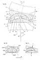
- FIG. 9 arepresents a perspective view of the prosthesis device according to the invention according to a variant with two stops exterior to the nucleus, held in a housing between pillars integral with the lower plate;
- FIG. 9 brepresents a perspective view of the prosthesis device according to the invention according to a variant with two stops exterior to the nucleus, each holding a pillar integral with the lower plate between its arms;
- FIG. 10represents a perspective view of a device according to the invention for fitting such a prosthesis
- FIG. 11represents a perspective view of a device according to the invention for inserting such a prosthesis, in position during the introduction laterally of the prosthesis between two vertebrae;
- FIG. 12represents a perspective view of an assembly tool with an insertion guide according to an embodiment of the invention.
- FIG. 13represents a perspective view of a prosthesis according to the invention, presented at the entrance of the insertion guide of the invention
- FIG. 14represents a perspective view of the instrumentation according to an embodiment of the invention when the prosthesis is ready to be impacted in the disc space.
- a prosthesis according to the prior art disclosed by the patent FR 2 730 159, represented in FIG. 6 c ,consists of a movable nucleus with two spherical surfaces oriented in the same direction, that may be laterally displaced between two plates and may allow incline without lateral displacement.
- the nucleusIn the extreme position, however, the nucleus is only kept on the exterior side by the furthest border of the spherical surface of the upper plate. Since this edge itself is already raised, there is a great risk that too high a vertical pressure or a horizontal parasitic force causes ejection of the nucleus towards the exterior of the prosthesis, causing intense pain and risks of immediate damage for the tissues surrounding the vertebral column, such as ligaments or spinal marrow.
- a prosthesis according to the inventionconsists of a lower plate ( 1 ) being articulated with an upper plate ( 3 ) around a nucleus ( 2 ) presenting two spherical sliding surfaces with the same orientation on both faces.
- the lower surface ( 21 ) of the nucleus ( 2 )is concave and slides on a complementary convex surface ( 12 ) provided by the upper face, known as internal, of the lower plate ( 1 ).
- the upper surface ( 23 )is convex and slides on a complementary concave surface ( 32 ) provided by the lower face, known as internal, of the upper plate ( 3 ).
- the radius of the lower contact surface ( 21 ) of the nucleus ( 2 )is a radius greater then that of its convex upper surface ( 23 ), the centres of the spheres providing its two contact surfaces being located on the same axis of symmetry (d 2 ) of these two surfaces.
- the two platespresent contact surfaces ( 12 , 32 ) the axes of symmetry (d 12 , d 32 ) of which are perpendicular to their external faces ( 10 , 30 ).
- the horizontal displacement part of the nucleus in one directiondue to the rotation on the upper sliding surface around its centre (cs), is compensated by a rotation of the nucleus on its lower sliding surface around its centre (ci) which induces horizontal displacement of the nucleus ( 2 ) and therefore of the centre (cs) of the upper sliding surface.
- the radii of the two spheres providing these sliding surfaces ( 12 , 21 , 23 , 32 )are determined so as to modify the lateral displacement of the plates by comparison with each other during their incline.
- the radii of these sliding surfacesmay be chosen so that the movement of the plate is reduced to an incline accompanied with a possible vertical component but without horizontal displacement of the upper plate relative to the lower plate.
- a central stopformed for example by a cylindrical block ( 4 ) protruding from the convex surface of the lower plate and cooperating with edges of a recess ( 22 ) arranged in the centre of the contact surface ( 21 ) of the lower concave surface of the nucleus.
- the lower platealso presents on its upper face an approximately cylindrical cavity ( 11 ) in which the edges ( 112 ) protrude from the contact surface ( 12 ) with the nucleus ( 2 ), and cooperate with the approximately cylindrical perimeter ( 20 ) of this nucleus to ensure an operation of annular stop for it while limiting its movement towards the exterior of the contact surface ( 12 ) that provides it.
- the internal surfaces of the plates, on their parts ( 113 , 331 ) exterior to the sliding surfaces,present a form capable of cooperating among themselves to limit by stop the incline of the plates with each other at a determined angle (a 1 ).
- the stop ( 4 )is provided by the convex surface ( 12 ) of the lower plate ( 1 ) and presents approximately the shape of an inverted cone, that is, its section is greater in its end ( 42 ) opposite the surface ( 12 ) that provides it.
- the interior surface ( 224 ) of the recess ( 22 )cooperates with the exterior surface ( 40 ) of the stop ( 4 ) to limit the raising of the nucleus when the latter is in furthest position against this stop ( 4 ).
- the different shapes and dimensions intervening in the stop mechanismscould be determined so as to coordinate the order of arrival at stop of the different parts.
- These shapes and dimensionscould be determined for example, so that the pieces reach stop at the same stage of movement, for example determined by angular incline (a 1 ) between the lower ( 1 ) and upper ( 3 ) plates.
- the annular stop operationis used very little or not at all, which allows the vertical obstruction of the prosthesis to be decreased.
- the lower surface ( 21 a ) of the nucleus ( 2 )may be approximately flat, and then slide on a contact surface ( 12 a ) of the lower plate ( 1 ), also approximately flat.
- the flatness of the contact surface ( 12 a ) of the lower plateallows the edges ( 112 ) of this plate that protrude from this surface to be particularly effective in their role of annular stop. Therefore, it is possible to manage without the central stop and thus to increase the common contact surface between the lower plate and the nucleus, which on the one hand, decreases the wear and tear of the pieces and on the other hand, the risk of marking the surface of the plate with placement of the contour of the recess ( 22 , FIG. 6 a ) in which is accommodated the central stop ( 4 , FIG. 6 a ) in other embodiments.
- the lower plate ( 1 )presents an approximately cylindrical cavity ( 11 ) on its upper face the flat bottom ( 15 ) of which receives an intermediate piece called block ( 5 ).
- This pieceis immobilized in the cavity ( 11 ) for example by the edges ( 112 ) of this cavity and presents on its upper face a convex surface ( 52 ) on which the lower concave surface ( 21 ) of the nucleus slides.
- This embodiment with the convex surface ( 52 ) on which the nucleus slidesfor example allows the good qualities of the surface necessary for the fluidity of movement and longevity of the prosthesis to be obtained more easily and at less cost. It also allows several models to be provided with blocks ( 5 ), of different shapes or qualities, that can be chosen in advance or at the time of the surgery according to applications with the same model of lower plate.
- the lower plate ( 1 )receives a block ( 5 ) in an approximately cylindrical cavity ( 11 ) presenting a vertical perforation that the stop ( 4 ) integral with the lower plate crosses.
- this blockOn its upper surface, this block supports a convex surface ( 52 ), on which the nucleus ( 2 ) and upper plate stack rests.
- the stop ( 4 )may be integral with the block ( 5 ) on its convex contact surface ( 52 )( FIG. 8 b ).
- the prosthesismay be produced in a variant where the axes of symmetry of the contact surfaces ( 12 , 15 , 52 , 21 , 23 , 32 ) or support ( 10 , 30 ) of one or more pieces are not merged.
- the pressure (F) exerted by the vertebrae on the two plates in the directions perpendicular to their external surfaces ( 10 , 30 )will then have the tendency to induce and continuously maintain an incline (a 3 , FIGS. 8 a , 8 b et 8 c ) between these plates ( 1 , 3 ), that is not zero, for example in the sense of lordosis.
- FIG. 8 aAn embodiment of such a variant is represented in FIG. 8 a where the axis of symmetry (d 12 ) of the contact surface ( 12 ) of the lower plate ( 1 ) forms an angle (a 2 ) determined with a direction (d 10 ) perpendicular to the external surface of this same lower plate, while the axis of symmetry (d 32 ) of the internal contact face ( 32 ) of the upper plate ( 3 ) is perpendicular to the external surface ( 30 ) of this same upper plate ( 3 ).
- the lower contact surface of the upper plate ( 3 )presents an axis of symmetry parallel to a direction perpendicular to the support surface ( 30 ) of the external face of this same upper plate ( 3 ).
- a devicein another variant according to the same principle represented in FIG. 8 b , includes a lower plate ( 1 ) providing a block ( 5 ) the upper contact surface of which ( 52 ) presents an axis of symmetry (d 52 ) forming an angle (a 2 ) determined with a direction (d 51 ) perpendicular to its lower face ( 51 ).
- the internal contact surfaces ( 15 , 32 ) of the lower ( 1 ) and upper ( 3 ) platespresent axes of symmetry perpendicular to the support surface ( 10 , 30 ) of their respective external faces.
- This block ( 5 )could be maintained fixed around an axis perpendicular to the lower plate ( 1 ) by any known means (not represented) such as wedge, grooves or complementary accidents of shape between the block ( 5 ) and the lower plate ( 1 ) that provides it.
- FIG. 8 cit is the nucleus ( 2 ) that presents two contact surfaces ( 21 , 23 ) the axes of symmetry of which (d 21 , d 23 ) form a determined angle (a 2 ) between them.
- the internal contact surfaces ( 12 , 32 ) of the lower ( 1 ) and upper ( 3 ) platespresent axes of symmetry perpendicular to the support surface ( 10 , 30 ) of their respective external faces.
- the angular correction (a 3 ) induced by the nucleus ( 2 )could then be kept constantly in the desired direction relative to the body of the patient by a rotation stop mechanism (not represented in FIG. 8 c ) of this same nucleus, such a mechanism being described later ( FIGS. 9 a and 9 b ).
- the device according to the inventionpresents an exterior stop mechanism, located outside the perimeter of the contact surfaces of the nucleus ( 2 ).
- this mechanismis formed of two protruding parts ( 6 ) protruding from the cylindrical exterior surface of the perimeter of the nucleus ( 2 ) in opposite directions.
- Each of these protruding partsis held in a housing ( 162 ) delimited by two pillars ( 161 ) integral with the lower plate ( 1 ).
- These pillarscooperate with the protruding part ( 6 ) or with the surface ( 20 ) of the perimeter of the nucleus or both for limiting the movements of this same nucleus in translation as in rotation parallel said plate.
- the housingis sufficiently large to allow small displacements of the nucleus required for the kinematics of the device, while being sufficiently narrow so that this same nucleus and the lower plate are adjacent in certain positions, for example, positions of maximum incline of the spinal column.
- the protruding part ( 6 ) or perimeter surface ( 20 ) of the nucleus ( 2 )then cooperates with the pillars ( 161 ) of the lower plate to retain this same nucleus and avoid any lateral ejection.
- the pillars ( 161 )present a larger section at the end than at the base, thus limiting the raising of the nucleus.
- this mechanismis formed of two protruding parts ( 6 ) protruding from the cylindrical exterior surface ( 20 ) of the perimeter of the nucleus ( 2 ) in opposite directions.
- Each of these protruding partspresents two arms delimiting a housing ( 66 ) which hold a pillar ( 163 ) integral with the lower plate ( 1 ).
- the pillars ( 163 )present a larger section at their end than at their base.
- stop ( 9 a and 9 b )may allow the central stop to be disposed of and to thus increase the contact surfaces which decreases the wear and tear.
- stop ( 6 )are also particularly valuable because of the limitation of the movements of the nucleus in rotation along an axis approximately parallel to the axis of the spinal column. In fact, this limitation makes it possible to use a corrective nucleus in which the contact surfaces present axes of symmetry that are not parallel, while maintaining in them the correction in a constant direction relative to the body of the patient.
- the lower ( 1 ) and upper ( 3 ) platesreceive means for bony anchoring on their external face, designed to immobilize the prosthesis between the vertebrae or adjacent elements of the spinal column.
- These anchoring meansmay be pins ( 8 ) or wings presenting a small cross section at their end away from the plate that provides them. These pins then are embedded or are impacted by punching in the material of the bony elements (V) between which the prosthesis is fitted, for example under the effect of the pressure exerted by the ligaments when the tools are withdrawn, the tools that kept the vertebrae separated.
- Driving in the pins in the material of the bony element (V, FIG. 6 )then prevents the prosthesis from sliding outside its site.
- the plates ( 1 , 3 )present one or more accidents of shape such as notches ( 7 ) or perforations (not represented) enabling catching of a grasping tool to remove the prosthesis from its site in case of need.
- the lower plate ( 1 )presents a convex upper contact surface ( 12 ) providing a central stop ( 4 ) and a cavity presenting edges ( 112 ) forming an annular stop.
- an insertion deviceis presented in the form of an element ( 9 ) called insertion guide, presenting an internal channel ( 90 ) approximately rectangular in section in which the prosthesis (P) can slide.
- This channel ( 9 )is formed from two semi-guides ( 91 , 92 ) with a cross section in the shape of a “U”, arranged inversely and fitted into each other.
- this guide ( 9 )presents one or more parts called support blocks or edges ( 910 , 920 ) protruding along its longitudinal axis (d 9 ).
- These support blocks ( 910 , 920 )form an extension of the walls of the channel called vertical ( 9 ) that form the small sides of the rectangular section of the channel ( 9 ).
- the instrumentation used for fitting the prosthesis according to the inventioncomprises an insertion guide ( 93 ) provided with an internal channel ( 90 ).
- This channel ( 90 )presents an approximately rectangular cross section, or with a shape approximately complementary to the exterior profile of the prosthesis.
- This internal channel ( 90 )is provided with dimensions and shape adequate for allowing the prosthesis to pass and to guide from one of its ends to the other, in a position and along a displacement approximately parallel to the external faces of its plates ( 1 , 3 ).
- the channel ( 90 ) of the insertion guide ( 93 )may include scallops in its walls opposite plates of the prosthesis.
- scallopsmake it possible to allow the anchoring means ( 8 , 81 ) to pass provided by the plates of the prosthesis, while guiding the latter sufficiently precisely in the channel.
- these scallopshave the shape of grooves ( 934 , 936 ) along the axis (d 9 ) of the channel provided by the internal walls of the channel opposite plates ( 1 , 3 ).
- the walls ( 931 , 932 ) of the channel ( 90 ) perpendicular to the plates of the prosthesis, that is, located in the plane containing the axis of the spinal column,are extended along the axis (d 9 ) of this channel over a distance determined so as to protrude relative to the walls of this same channel that are parallel to the plates of the prosthesis. Since these extensions thus form the protruding parts, or support edges, that may be inserted in the intervertebral space to maintain the separation of the plates from the two vertebrae surrounding this space.
- the height of these support edges ( 931 , 932 )is determined so as to maintain adequate space for allowing the introduction of the prosthesis and its anchoring means ( 8 , 81 ), according to the method of anchoring provided. If the anchoring means are formed from sockets ( 8 ) or wings ( 81 ) before being introduced freely in the space, the support edges will have sufficient height to allow the height of these sockets or wings to pass. If the anchoring means are formed from wings having to penetrate the vertebral plates by a hollowed trench in the surface of these plates and opening laterally, the height of these support edges could be sufficiently low to allow the height of the prosthesis to pass but not the wings.
- the surgeonbegins by removing the vertebral disc or its debris, and then uses distraction tools to increase the disc space available between the two vertebrae having to receive the prosthesis.
- distraction toolsare often formed with an elongated handle providing a flat part at the end. This flat end is introduced between the vertebrae, then it is made to pivot to increase the separation of the vertebrae.
- the internal channel ( 90 ) of the insertion guide ( 93 )is provided to be able to be threaded around such distraction tools, once they are in place between the vertebrae.
- the insertion guideis pushed so as to introduce its edges ( 931 , 932 ) between the vertebrae, in a plane approximately parallel to the spinal column.
- the distraction toolsmay then be removed from the spinal column by making them slide in the channel ( 90 ) of the insertion guide, while the height of the support edges preserves sufficient space between the vertebrae to allow fitting of the prosthesis.
- the insertion guide ( 93 )presents means for interlocking with a guide assembly tool ( 94 ), used to bring it near the spinal column and facilitating its fitting.
- This guide assembly tool ( 94 )is also usable for removing the insertion guide and its support edges, and allowing the vertebrae to tighten on the prosthesis, once the latter is in place.
- FIGS. 12 a and 12 bSuch a guide assembly tool ( 94 ) is illustrated in FIGS. 12 a and 12 b .
- This tool ( 94 )consists of two elongated tubes ( 941 , 946 ) articulated to each other by means ( 945 ) located at one end, called assembling, of this tool.
- These two elongated tubes at their end located opposite the assembling end, eachprovide interlocking means for insertion guide ( 93 ).
- These interlocking meansmay comprise, for example, a hook ( 942 , 947 ) on each tube ( 941 , 946 ) the opening of which is located opposite the other tube.
- each hook ( 942 , 947 )When the guide assembly tool ( 94 ) is approached by the insertion guide ( 93 ), the fact of tightening the tubes to each other around their articulation makes it possible for each hook ( 942 , 947 ) to tightly encircle a tongue ( 934 , 936 ) in the shape of a “T” protruding on each groove ( 933 , 935 ) of the insertion guide.
- a rod ( 943 , 948 )Within and in the axis of each tube ( 941 , 946 ) is found a rod ( 943 , 948 ) that may be displaced longitudinally relative to the tubes by screwing means comprising a screwing wheel ( 944 , 949 ).
- These means ( 934 , 936 ) of interlocking the insertion guide ( 93 ) or others provided by said insertion guidealso make it possible to guide and interlock means of approach ( 95 ) to this insertion guide.
- These means ( 95 ) of approachinclude means for positioning the prosthesis, these means of positioning being provided to position and maintain the assembled prosthesis in a determined position relative to these means ( 95 ) of approach even in the absence of the insertion guide ( 93 ).
- This positioning of the prosthesis on the approach meansmakes it possible for the interlocking of the approach means and the insertion guide to put the prosthesis in a position making it possible for it to be easily displaced from these same means of approach up to in the internal channel ( 90 ) of the insertion guide ( 93 ).
- these approach means ( 95 )include two shafts ( 951 , 952 ) connected to each other by articulation ( 955 ) so as to come to pinch the prosthesis (P) between two flattened parts ensuring a determined position of the prosthesis relative to these approach means.
- the ends of these shafts opposite the articulationincluding interlocking means ( 953 , 954 ) capable of cooperating with the interlocking means ( 934 , 936 ) of insertion guide ( 93 ) to ensure a determined position of approach means ( 95 ) relative to the insertion guide ( 93 ) as well as certain stability to this assembly.
- these interlocking meansmay in particular comprise a scalloping in which the arms come to encircle the exterior of the groove ( 933 , 935 ) of the insertion guide while gliding under the upper bar of the “T” formed by the tongue ( 934 , 936 ) provided by this same insertion guide.
- the prosthesisis therefore in a stable position relative to the spinal column, and may be inserted in the insertion guide then slide up to the disc space.
- This displacementis achievable here with the aid of impacting means, or impactor ( 96 ) comprising an impacting end capable of pressing on the assembled prosthesis, distributed on both plates and without touching the nucleus.
- This impactorincludes a central elongated part ( 960 ) that can be inserted in guiding means as an opening in the shape of a “U” provided by approach means ( 95 ) at their articulated end ( 955 ).
- This impactorincludes another end ( 962 ) called assembling or striking, that can act to apply a continuous pressure or repeated shocks, with the hand or by any known tool or apparatus.
- Such an action, applied on the assembling end ( 962 ) of the impactor in the axis (d 9 ) of the channel ( 90 )then will be reverberated by the end ( 961 ) on the prosthesis, so as to cause its entrance then sliding in the channel ( 90 ) of the insertion guide ( 93 ), then its insertion or impaction in the intervertebral space.
- the inventionproposes an intervertebral disc prosthesis device comprising at least three pieces, which parts include a plate ( 1 ) called lower and a plate ( 3 ) called upper ( 3 ) producing around at least one intermediate part called nucleus ( 2 ) an articulation by support or sliding between loadbearing surfaces ( 12 , 15 , 21 , 23 , 32 ) of said pieces, one of these pieces including at least one protruding part or accident of shape cooperating with the shape of at least one other of said pieces to form an stop limiting the possibilities of movement of the nucleus, characterized in that this stop operation uses at least one stop external to the loadbearing surfaces comprising at least one part ( 161 , 163 ) protruding from at least one plate ( 1 ), located outside the loadbearing surface ( 12 , 15 ) of said plate and including a face directed towards the interior of the prosthesis, this face cooperating with a peripheral part ( 6 ) of the nucleus ( 21 , 23 ) situated outside its loadbea
- the loadbearing surfaces ( 21 , 21 a , 23 ) of the nucleus ( 2 ) in contact with the lower plate ( 1 ) and upper plate ( 3 )present axes of symmetry (d 21 , d 23 , respectively) forming between them a determined angle (a 2 ) that is not zero, so that a pressure (F) exerted on the two plates ( 1 , 3 ) along directions perpendicular to their external surfaces induces an incline (a 3 ) of these plates with each other.
- this external stoplimits the movements in rotation of the nucleus ( 2 ) relative to at least one plate ( 1 ) by contact between parts ( 6 , 161 , 163 ) supporting each other by stop surfaces, this support being done along a direction approximately parallel to the normal of each of these stop surfaces.
- the external stopincludes a tongue ( 6 ) protruding form the nucleus ( 6 ) which cooperates with one of the plates ( 1 ) by confining this tongue ( 6 ) in a housing ( 162 ) delimited by pillars ( 161 ) protruding from the internal face of this same plate ( 1 ) or by a recess ( 66 ) separating this tongue into two arms encircling a pillar ( 163 ) protruding from the internal face of this same plate ( 1 ), the internal face of a plate being defined at that oriented on the side of the nucleus.
- the end of at least one pillar ( 161 , 162 , 163 )presents a section greater than its base, this enlargement of the pillar cooperating with the shape of the external stop tongue ( 6 ) of the nucleus ( 2 ) to limit the raising of this same nucleus relative to the plate ( 1 ) providing this pillar.
- the inventionalso proposes an intervertebral disc prosthesis device comprising at least three pieces, including a plate ( 1 ) called lower and a plate ( 3 ) called upper ( 3 ) producing around at least one intermediate element called nucleus ( 2 ) an articulation by support or sliding between loadbearing surfaces ( 12 , 15 , 21 , 23 , 32 ) of said parts, one of these parts including at least one protruding part or accident of shape cooperating with the shape of at least one other of said parts to form an stop limiting the possibilities of movement of the nucleus, characterized in that the loadbearing surfaces ( 21 , 21 a , 23 ) of the nucleus ( 2 ) in contact with the lower plate ( 1 ) and upper plate ( 3 ) present axes of symmetry (d 21 , d 23 , respectively) forming between them a determined angle (a 2 ) that is not zero so that a pressure (F) exerted on the two plate ( 1 , 3 ) along directions per
- this deviceis characterized in that the operation of the stop uses at least one stop external to the loadbearing surfaces comprising at least one part ( 161 , 163 ) protruding from at least one plate ( 1 ) located outside the loadbearing surface ( 12 , 15 ) of said plate and including a face directed towards the interior of the prosthesis, this face cooperating with a peripheral part ( 6 ) of the nucleus located outside its loadbearing surfaces ( 21 , 23 ) and in which the surface is directed towards the exterior of the nucleus, to limit the displacements of the nucleus in translation or in rotation or both in a plane approximately transverse to the spinal column.
- the loadbearing surfaces ( 12 , 32 ) provided by the internal face of the lower plate ( 1 ) and the internal face of the upper plate ( 3 )are each in complementary contact with a supporting surface ( 21 , 23 , respectively) of the nucleus ( 2 ), and each present a shape, convex and concave, respectively, or inversely, this nucleus itself presenting a perimeter ( 20 ) approximately cylindrical along the axis of symmetry of its contact faces ( 21 , 32 ).
- the internal face of the lower plate ( 1 )presents a loadbearing surface ( 12 a ) cooperating with a loadbearing surface ( 21 a ) of the lower face of the nucleus ( 2 ), this same nucleus including on its upper face a convex loadbearing surface ( 23 ) in complementary contact with a concave loadbearing surface ( 32 ) of the internal face of the upper plate ( 3 ) the loadbearing surface ( 12 a ) of the internal face of the lower plate being sufficiently extended to allow movement of the nucleus relative to this same lower plate.
- an intermediate element called block ( 5 )is added on the internal face of one (1) of the plates and produces an articulation with the other plate ( 3 ) around the nucleus ( 2 ) which nucleus presents a concave loadbearing surface ( 21 ) and a convex loadbearing surface ( 23 ) these two loadbearing surfaces being in contact in a complementary way with one loadbearing surface ( 52 ) of the block ( 5 ) one, and with a loadbearing surface ( 32 ) of the internal face of the plate ( 3 ) not including block, for the other.
- the axis of symmetry (d 52 ) of the convex loadbearing surface ( 52 ) of the block ( 5 )forms a determined angle (a 4 ) with an axis (d 51 ) perpendicular to its surface ( 51 ) with contact of the plate ( 1 ) so that a pressure (F) exerted on the two plates ( 1 , 3 ) along directions perpendicular to their external faces induces an incline (a 5 ) of the plates with each other.
- At least one of the loadbearing surfaces ( 12 , 52 , 21 , 23 , 32 ) allowing articulationhas a shape making up part of a sphere.
- the loadbearing surfaces of the two faces of the nucleus ( 2 )have shapes making up parts of a sphere, the face presenting a concave loadbearing surface ( 21 ) having a radius greater than that of the face presenting a convex loadbearing surface ( 23 ).
- each of the plates ( 1 , 3 )includes on its external face one or more protruding parts with small section forming a bony anchoring, these protruding parts coming to be embedded or impacted in the surface of contiguous bony elements (V) under the effect of pressure, once the prosthesis is in position between two vertebrae or bony elements.
- one or more of the pieces of the prosthesisinclude accidents of shape, notches ( 7 ) or perforations likely to see a tool again to facilitate the extraction of said prosthesis.
- the plates ( 1 , 3 )are composed of an alloy with base of stainless steel with cobalt-chromium and the nucleus ( 2 ) has polyethylene base.
- the inventionproposes instrumentation for inserting or fitting the prosthesis according to one of claims 1 to 15 characterized in that it comprises an insertion guide ( 9 , 93 ) including an internal channel ( 90 ) presenting an end in which certain edges or support edges ( 910 , 920 , 931 , 932 ), protrude from the others along the longitudinal axis (d 9 ) of the channel so as to be able to take the place of distraction tools of a known type previously used to increase the opening of the disc space, this channel ( 90 ) presenting an internal section capable of surrounding these same distraction tools while they maintain this opening, then allowing their extraction through said channel while said support edges ( 910 , 920 , 931 , 932 ), for their part, preserve the opening of the disc space by replacing the distraction tools, then receiving and guiding the prosthesis (P) for insertion in this disc space.
- an insertion guide ( 9 , 93 )including an internal channel ( 90 ) presenting an end in which certain edges or support edges ( 910 , 920
- the internal channel ( 90 )presents an approximately rectangular section or with a shape approximately complementary to the exterior profile of the prosthesis, taken in a section along the plane perpendicular to the direction of insertion.
- the support edges ( 931 , 932 ) of insertion guide ( 93 )form an extension of the channel ( 90 ) walls located on a plane containing the axis of the spinal column.
- the insertion guide ( 9 )is formed from at least two elements ( 91 , 92 ) separated along one or more planes parallel to the longitudinal axis (d 9 ) of the channel, these parts each including at least one portion of the transverse section of the channel and being able to be spread apart according to a determined angle (a 9 ) and allowing the introduction and sliding of the prosthesis (P) in the channel.
- the internal surface of the channel ( 90 ) on its walls opposite external faces of the plates ( 1 , 3 ) of the prosthesis (P),includes at least one groove ( 913 , 914 ) allowing the passage of protruding parts ( 8 , 81 ) for anchoring provided by these plates during displacement of the prosthesis in this channel ( 90 ).
- the instrumentationcomprises approach means ( 95 ) of the prosthesis capable of receiving the prosthesis and of maintaining with it all the different components, these approach means ( 95 ) being able to be connected by interlocking means to the insertion guide ( 93 ) so as to present the prosthesis at the entrance of the channel ( 90 ) in a position appropriate for allowing its entrance into this channel ( 90 ).
- the instrumentscomprises insertion means, called impactor ( 96 ) of the prosthesis in the channel ( 90 ) of the insertion guide ( 93 ) then into the disc space, this impactor being guided by the support means ( 95 ) so as to be in contact with the prosthesis in its part opposite the entrance of the channel ( 90 ), this impactor ( 96 ) being able to apply or transmit a pressure or repeated shocks to the prosthesis to cause its sliding in the channel, then its insertion in the disc space.
- impactor ( 96 )insertion means, called impactor ( 96 ) of the prosthesis in the channel ( 90 ) of the insertion guide ( 93 ) then into the disc space, this impactor being guided by the support means ( 95 ) so as to be in contact with the prosthesis in its part opposite the entrance of the channel ( 90 ), this impactor ( 96 ) being able to apply or transmit a pressure or repeated shocks to the prosthesis to cause its sliding in the channel, then its insertion in the disc space.
- the support meansinclude two shafts ( 951 , 952 ) connected by an axis to a assembling end ( 955 ), these shafts being able to be closed up to pinch the prosthesis (P) between them and to maintain it so assembled, these two shafts each providing connection means to the guide for use ( 93 ), this connection then maintaining these two shafts closed up on the prosthesis.
Landscapes
- Health & Medical Sciences (AREA)
- Engineering & Computer Science (AREA)
- Biomedical Technology (AREA)
- Orthopedic Medicine & Surgery (AREA)
- Transplantation (AREA)
- Neurology (AREA)
- Heart & Thoracic Surgery (AREA)
- Oral & Maxillofacial Surgery (AREA)
- Cardiology (AREA)
- Vascular Medicine (AREA)
- Life Sciences & Earth Sciences (AREA)
- Animal Behavior & Ethology (AREA)
- General Health & Medical Sciences (AREA)
- Public Health (AREA)
- Veterinary Medicine (AREA)
- Physical Education & Sports Medicine (AREA)
- Prostheses (AREA)
- Surgical Instruments (AREA)
Abstract
Description
- separating the vertebrae with the aid of known instruments, for example distraction tools;
- sliding the insertion guide (9)around the distraction tools so as to introduce the support edges (910,920) between the vertebrae (V);
- release and extraction of the distraction tools, the vertebrae being kept spread apart by the support edges of the insertion guide;
- introduction of the prosthesis ready for fitting into the channel, and sliding to near the spinal column;
- adjustment of the incline of the prosthesis according to conformation of the space available between the vertebrae with possible separating of the two parts (91,92) of the channel according to a corresponding angle (a9) to help with this adjustment;
- positioning of the prosthesis in the intervertebral space by pushing by the interior of the channel;
- extraction of the support blocks (910,920) of the channel outside the intervertebral space and impacting blocks for bony anchoring in the vertebrae (V).
Claims (112)
Priority Applications (3)
| Application Number | Priority Date | Filing Date | Title |
|---|---|---|---|
| US12/025,677US9333095B2 (en) | 2001-05-04 | 2008-02-04 | Intervertebral disc prosthesis, surgical methods, and fitting tools |
| US15/150,316US9788964B2 (en) | 2001-05-04 | 2016-05-09 | Intervertebral disc prosthesis, surgical methods, and fitting tools |
| US15/784,559US20180098859A1 (en) | 2001-05-04 | 2017-10-16 | Intervertebral disc prosthesis, surgical methods, and fitting tools |
Applications Claiming Priority (4)
| Application Number | Priority Date | Filing Date | Title |
|---|---|---|---|
| FR0105982 | 2001-05-04 | ||
| FR0105982AFR2824261B1 (en) | 2001-05-04 | 2001-05-04 | INTERVERTEBRAL DISC PROSTHESIS AND IMPLEMENTATION METHOD AND TOOLS |
| FR01/05982 | 2001-05-04 | ||
| PCT/IB2002/002998WO2002089701A2 (en) | 2001-05-04 | 2002-05-03 | Intervertebral disc prosthesis and fitting tools |
Related Parent Applications (1)
| Application Number | Title | Priority Date | Filing Date |
|---|---|---|---|
| PCT/IB2002/002998A-371-Of-InternationalWO2002089701A2 (en) | 2001-05-04 | 2002-05-03 | Intervertebral disc prosthesis and fitting tools |
Related Child Applications (1)
| Application Number | Title | Priority Date | Filing Date |
|---|---|---|---|
| US12/025,677ContinuationUS9333095B2 (en) | 2001-05-04 | 2008-02-04 | Intervertebral disc prosthesis, surgical methods, and fitting tools |
Publications (2)
| Publication Number | Publication Date |
|---|---|
| US20040243240A1 US20040243240A1 (en) | 2004-12-02 |
| US7326250B2true US7326250B2 (en) | 2008-02-05 |
Family
ID=8862982
Family Applications (4)
| Application Number | Title | Priority Date | Filing Date |
|---|---|---|---|
| US10/476,565Expired - LifetimeUS7326250B2 (en) | 2001-05-04 | 2002-05-03 | Intervertebral disc prosthesis and fitting tools |
| US12/025,677Expired - Fee RelatedUS9333095B2 (en) | 2001-05-04 | 2008-02-04 | Intervertebral disc prosthesis, surgical methods, and fitting tools |
| US15/150,316Expired - LifetimeUS9788964B2 (en) | 2001-05-04 | 2016-05-09 | Intervertebral disc prosthesis, surgical methods, and fitting tools |
| US15/784,559AbandonedUS20180098859A1 (en) | 2001-05-04 | 2017-10-16 | Intervertebral disc prosthesis, surgical methods, and fitting tools |
Family Applications After (3)
| Application Number | Title | Priority Date | Filing Date |
|---|---|---|---|
| US12/025,677Expired - Fee RelatedUS9333095B2 (en) | 2001-05-04 | 2008-02-04 | Intervertebral disc prosthesis, surgical methods, and fitting tools |
| US15/150,316Expired - LifetimeUS9788964B2 (en) | 2001-05-04 | 2016-05-09 | Intervertebral disc prosthesis, surgical methods, and fitting tools |
| US15/784,559AbandonedUS20180098859A1 (en) | 2001-05-04 | 2017-10-16 | Intervertebral disc prosthesis, surgical methods, and fitting tools |
Country Status (15)
| Country | Link |
|---|---|
| US (4) | US7326250B2 (en) |
| EP (3) | EP3195832A1 (en) |
| JP (1) | JP4226907B2 (en) |
| KR (2) | KR100941116B1 (en) |
| CN (3) | CN100401996C (en) |
| AT (1) | ATE515986T1 (en) |
| BR (1) | BR0209351B1 (en) |
| CA (2) | CA2446095C (en) |
| ES (2) | ES2367685T3 (en) |
| FR (1) | FR2824261B1 (en) |
| IL (2) | IL158740A0 (en) |
| MX (1) | MXPA03010083A (en) |
| RU (1) | RU2296540C2 (en) |
| WO (1) | WO2002089701A2 (en) |
| ZA (1) | ZA200308355B (en) |
Cited By (100)
| Publication number | Priority date | Publication date | Assignee | Title |
|---|---|---|---|---|
| US20040225363A1 (en)* | 2003-05-06 | 2004-11-11 | Marc Richelsoph | Artificial intervertebral disc |
| US20050033435A1 (en)* | 2003-08-04 | 2005-02-10 | Spine Next | Intervertebral disk prosthesis |
| US20050143824A1 (en)* | 2003-05-06 | 2005-06-30 | Marc Richelsoph | Artificial intervertebral disc |
| US20050154269A1 (en)* | 2004-01-13 | 2005-07-14 | University Of Toledo | Noninvasive birefringence compensated sensing polarimeter |
| US20050273174A1 (en)* | 2003-08-05 | 2005-12-08 | Gordon Charles R | Expandable articulating intervertebral implant with spacer |
| US20060020341A1 (en)* | 2004-06-16 | 2006-01-26 | Susanne Schneid | Intervertebral implant |
| US20060116768A1 (en)* | 2002-10-31 | 2006-06-01 | Krueger David J | Movable disc implant |
| US20060178744A1 (en)* | 2005-02-04 | 2006-08-10 | Spinalmotion, Inc. | Intervertebral prosthetic disc with shock absorption |
| US20060229725A1 (en)* | 2003-07-22 | 2006-10-12 | Beat Lechmann | Intervertebral implant comprising dome-shaped joint surfaces |
| US20070093900A1 (en)* | 2005-09-26 | 2007-04-26 | Williams Lytton A | Modular articulating and fusion spinal disc implant system |
| US20070179611A1 (en)* | 2005-12-22 | 2007-08-02 | Dipoto Gene P | Methods and devices for replacement of intervertebral discs |
| US20070213720A1 (en)* | 2006-03-08 | 2007-09-13 | Southwest Research Institute | Dynamic interbody device |
| US20070260317A1 (en)* | 2003-07-31 | 2007-11-08 | Ankney David W | Transforaminal prosthetic spinal disc replacement |
| US20070282449A1 (en)* | 2006-04-12 | 2007-12-06 | Spinalmotion, Inc. | Posterior spinal device and method |
| US20080015698A1 (en)* | 2002-10-31 | 2008-01-17 | Marino James F | Spinal disc implant |
| US20080154301A1 (en)* | 2004-08-06 | 2008-06-26 | Spinalmotion, Inc. | Methods and Apparatus for Intervertebral Disc Prosthesis Insertion |
| US20080200984A1 (en)* | 2007-02-16 | 2008-08-21 | Ldr Medical | Intervertebral Disc Prosthesis Insertion Assemblies |
| US20080215155A1 (en)* | 2003-05-27 | 2008-09-04 | Spinalmotion, Inc. | Intervertebral prosthetic disc |
| US20080228274A1 (en)* | 2002-09-19 | 2008-09-18 | Spinalmotion, Inc. | Intervertebral Prosthesis |
| US20080234764A1 (en)* | 2007-01-19 | 2008-09-25 | Landry Michael E | Artificial functional spinal unit system and method for use |
| US20080262620A1 (en)* | 2003-05-06 | 2008-10-23 | Aesculap Implant Systems, Inc. | Spring member for artificial intervertebral disc and method of inserting disc |
| US20080286194A1 (en)* | 2005-03-02 | 2008-11-20 | Tom Eriksson | Metal-Vanadium-Oxide Product and Producing Process |
| US20090043391A1 (en)* | 2007-08-09 | 2009-02-12 | Spinalmotion, Inc. | Customized Intervertebral Prosthetic Disc with Shock Absorption |
| US20090076608A1 (en)* | 2007-09-17 | 2009-03-19 | Vermillion Technologies, Llc | Intervertebral disc replacement prosthesis |
| US20090105835A1 (en)* | 2007-10-22 | 2009-04-23 | Spinalmotion, Inc. | Vertebral Body Replacement and Method for Spanning a Space Formed upon Removal of a Vertebral Body |
| US20090132054A1 (en)* | 2004-12-22 | 2009-05-21 | Ldr Medical | Intervertebral Disc Prosthesis |
| US7575600B2 (en) | 2004-09-29 | 2009-08-18 | Kyphon Sarl | Artificial vertebral disk replacement implant with translating articulation contact surface and method |
| US20090205188A1 (en)* | 2004-07-30 | 2009-08-20 | Spinalmotion, Inc. | Intervertebral Prosthetic Disc With Metallic Core |
| US20090276051A1 (en)* | 2008-05-05 | 2009-11-05 | Spinalmotion, Inc. | Polyaryletherketone Artificial Intervertebral Disc |
| US20100004746A1 (en)* | 2008-07-02 | 2010-01-07 | Spinalmotion, Inc. | Limited Motion Prosthetic Intervertebral Disc |
| US20100016973A1 (en)* | 2008-07-18 | 2010-01-21 | Spinalmotion, Inc. | Posterior Prosthetic Intervertebral Disc |
| US20100016972A1 (en)* | 2008-07-17 | 2010-01-21 | Spinalmotion, Inc. | Artificial Intervertebral Disc Placement System |
| US20100023128A1 (en)* | 2008-07-23 | 2010-01-28 | Malberg Marc I | Modular nucleus pulposus prosthesis |
| US20100030335A1 (en)* | 2008-01-25 | 2010-02-04 | Spinalmotion, Inc. | Compliant Implantable Prosthetic Joint With Preloaded Spring |
| US20100042152A1 (en)* | 2008-08-12 | 2010-02-18 | Blackstone Medical Inc. | Apparatus for Stabilizing Vertebral Bodies |
| US20100049040A1 (en)* | 2003-01-31 | 2010-02-25 | Spinalmotion, Inc. | Spinal Midline Indicator |
| US7670377B2 (en) | 2003-11-21 | 2010-03-02 | Kyphon Sarl | Laterally insertable artifical vertebral disk replacement implant with curved spacer |
| US20100069976A1 (en)* | 2003-01-31 | 2010-03-18 | Spinalmotion, Inc. | Intervertebral Prosthesis Placement Instrument |
| US20100087868A1 (en)* | 2008-04-11 | 2010-04-08 | Spinalmotion, Inc. | Motion Limiting Insert For An Artificial Intervertebral Disc |
| US20100125334A1 (en)* | 2008-11-14 | 2010-05-20 | David Krueger | Spinal fusion device |
| US20100262250A1 (en)* | 2006-11-07 | 2010-10-14 | Kellar Franz W | Prosthetic ball-and-socket joint |
| US20110022175A1 (en)* | 2004-08-13 | 2011-01-27 | Stryker Spine | Insertion guide for a spinal implant |
| US20110046744A1 (en)* | 2001-07-16 | 2011-02-24 | Spinecore, Inc. | Intervertebral spacer device having recessed notch pairs for manipulation using a surgical tool |
| US7905919B2 (en) | 2006-11-07 | 2011-03-15 | Biomedflex Llc | Prosthetic joint |
| US20110077739A1 (en)* | 2005-09-23 | 2011-03-31 | Ldr Medical | Intervertebral disc prosthesis |
| US8029574B2 (en) | 2006-11-07 | 2011-10-04 | Biomedflex Llc | Prosthetic knee joint |
| US8052723B2 (en) | 2003-08-05 | 2011-11-08 | Flexuspine Inc. | Dynamic posterior stabilization systems and methods of use |
| US8070823B2 (en) | 2006-11-07 | 2011-12-06 | Biomedflex Llc | Prosthetic ball-and-socket joint |
| US8157844B2 (en) | 2007-10-22 | 2012-04-17 | Flexuspine, Inc. | Dampener system for a posterior stabilization system with a variable length elongated member |
| US8162994B2 (en) | 2007-10-22 | 2012-04-24 | Flexuspine, Inc. | Posterior stabilization system with isolated, dual dampener systems |
| US8182514B2 (en) | 2007-10-22 | 2012-05-22 | Flexuspine, Inc. | Dampener system for a posterior stabilization system with a fixed length elongated member |
| US8187330B2 (en) | 2007-10-22 | 2012-05-29 | Flexuspine, Inc. | Dampener system for a posterior stabilization system with a variable length elongated member |
| US8241359B2 (en) | 2006-02-15 | 2012-08-14 | Ldr Medical | Transforaminal intersomatic cage for an intervertebral fusion graft and an instrument for implanting the cage |
| US8262700B2 (en) | 2007-07-12 | 2012-09-11 | Ldr Medical | Transverse spinal linking device and system |
| US8267965B2 (en) | 2007-10-22 | 2012-09-18 | Flexuspine, Inc. | Spinal stabilization systems with dynamic interbody devices |
| US8267999B2 (en) | 2002-11-05 | 2012-09-18 | Ldr Medical | Intervertebral disc prosthesis |
| US8308812B2 (en) | 2006-11-07 | 2012-11-13 | Biomedflex, Llc | Prosthetic joint assembly and joint member therefor |
| US8343219B2 (en) | 2007-06-08 | 2013-01-01 | Ldr Medical | Intersomatic cage, intervertebral prosthesis, anchoring device and implantation instruments |
| US8500749B2 (en)* | 2011-04-19 | 2013-08-06 | Prescient Surgical Designs, Llc | Apparatus and method for inserting intervertebral implants |
| US8512413B2 (en) | 2006-11-07 | 2013-08-20 | Biomedflex, Llc | Prosthetic knee joint |
| US8523912B2 (en) | 2007-10-22 | 2013-09-03 | Flexuspine, Inc. | Posterior stabilization systems with shared, dual dampener systems |
| US8545567B1 (en) | 2008-11-14 | 2013-10-01 | David Krueger | Spinal fusion device |
| US8632591B2 (en) | 2007-06-15 | 2014-01-21 | Ldr Medical | Nucleus prostheses |
| US20140052256A1 (en)* | 2003-07-31 | 2014-02-20 | David W. Ankney | Transforaminal Prosthetic Spinal Disc Replacement and Methods Thereof |
| US8758358B2 (en) | 2001-07-16 | 2014-06-24 | Spinecore, Inc. | Instrumentation for repositioning and extraction an artificial intervertebral disc from an intervertebral space |
| US8771284B2 (en) | 2005-11-30 | 2014-07-08 | Ldr Medical | Intervertebral disc prosthesis and instrumentation for insertion of the prosthesis between the vertebrae |
| US8858635B2 (en) | 2004-02-04 | 2014-10-14 | Ldr Medical | Intervertebral disc prosthesis |
| US8858564B2 (en) | 2001-02-15 | 2014-10-14 | Spinecore, Inc. | Wedge plate inserter/impactor and related methods for use in implanting an artificial intervertebral disc |
| US8906095B2 (en) | 2011-03-11 | 2014-12-09 | FBC Device ApS | Spinal implant, instrument for preparation and method of use |
| US8940051B2 (en) | 2011-03-25 | 2015-01-27 | Flexuspine, Inc. | Interbody device insertion systems and methods |
| US8974497B2 (en) | 2006-12-21 | 2015-03-10 | Ldr Medical | Vertebral support device |
| US8974532B2 (en) | 2004-04-28 | 2015-03-10 | Ldr Medical | Intervertebral disc prosthesis |
| US9005306B2 (en) | 2006-11-07 | 2015-04-14 | Biomedflex, Llc | Medical Implants With Compliant Wear-Resistant Surfaces |
| US9005307B2 (en) | 2006-11-07 | 2015-04-14 | Biomedflex, Llc | Prosthetic ball-and-socket joint |
| US9132020B2 (en) | 2001-07-16 | 2015-09-15 | Spinecore, Inc. | Wedge ramp distractor for use in implanting artificial intervertebral discs |
| US9248025B2 (en) | 2005-06-29 | 2016-02-02 | Ldr Medical | Instrumentation and methods for inserting an intervertebral disc prosthesis |
| US9320610B2 (en) | 2011-08-16 | 2016-04-26 | Stryker European Holdings I, Llc | Expandable implant |
| US9333095B2 (en) | 2001-05-04 | 2016-05-10 | Ldr Medical | Intervertebral disc prosthesis, surgical methods, and fitting tools |
| US9364338B2 (en) | 2008-07-23 | 2016-06-14 | Resspond Spinal Systems | Modular nucleus pulposus prosthesis |
| US20160220285A1 (en)* | 2013-07-01 | 2016-08-04 | Biospine Implants | Dynamic intervertebral stabilisation device |
| US9408715B2 (en) | 2009-04-15 | 2016-08-09 | DePuy Synthes Products, Inc. | Arcuate fixation member |
| US9445913B2 (en) | 2009-04-15 | 2016-09-20 | DePuy Synthes Products, Inc. | Arcuate fixation member |
| US9492288B2 (en) | 2013-02-20 | 2016-11-15 | Flexuspine, Inc. | Expandable fusion device for positioning between adjacent vertebral bodies |
| US9517144B2 (en) | 2014-04-24 | 2016-12-13 | Exactech, Inc. | Limited profile intervertebral implant with incorporated fastening mechanism |
| US9526628B2 (en) | 2008-11-14 | 2016-12-27 | David Krueger | Spinal fusion device |
| US9526627B2 (en) | 2011-11-17 | 2016-12-27 | Exactech, Inc. | Expandable interbody device system and method |
| US9566157B2 (en) | 2006-11-07 | 2017-02-14 | Biomedflex, Llc | Three-member prosthetic joint |
| US9655741B2 (en) | 2003-05-27 | 2017-05-23 | Simplify Medical Pty Ltd | Prosthetic disc for intervertebral insertion |
| US9782271B2 (en) | 2008-02-28 | 2017-10-10 | Stryker European Holdings I, Llc | Expandable intervertebral implant |
| US9883950B2 (en)* | 2006-07-24 | 2018-02-06 | Centinel Spine Llc | Intervertebral implant with keel |
| US9883945B2 (en) | 2008-03-11 | 2018-02-06 | Simplify Medical Pty Ltd | Artificial intervertebral disc with lower height |
| US20180064550A1 (en)* | 2003-07-31 | 2018-03-08 | Globus Medical, Inc. | Prosthetic spinal disc replacement and methods thereof |
| US20180140433A1 (en)* | 2014-12-04 | 2018-05-24 | Ben Cannon | Adjustable total disc replacement device |
| US10342675B2 (en) | 2013-03-11 | 2019-07-09 | Stryker European Holdings I, Llc | Expandable implant |
| US10398565B2 (en) | 2014-04-24 | 2019-09-03 | Choice Spine, Llc | Limited profile intervertebral implant with incorporated fastening and locking mechanism |
| US10603185B2 (en) | 2004-02-04 | 2020-03-31 | Ldr Medical | Intervertebral disc prosthesis |
| US10687958B2 (en)* | 2011-02-23 | 2020-06-23 | Globus Medical, Inc. | Six degree spine stabilization devices and methods |
| US11452618B2 (en) | 2019-09-23 | 2022-09-27 | Dimicron, Inc | Spinal artificial disc removal tool |
| US11839554B2 (en) | 2020-01-23 | 2023-12-12 | Robert S. Bray, Jr. | Method of implanting an artificial disc replacement device |
| US11938035B2 (en) | 2019-12-04 | 2024-03-26 | Robert S. Bray, Jr. | Artificial disc replacement device |
Families Citing this family (173)
| Publication number | Priority date | Publication date | Assignee | Title |
|---|---|---|---|---|
| US6936071B1 (en)* | 1999-07-02 | 2005-08-30 | Spine Solutions, Inc. | Intervertebral implant |
| US6673113B2 (en)* | 2001-10-18 | 2004-01-06 | Spinecore, Inc. | Intervertebral spacer device having arch shaped spring elements |
| FR2827156B1 (en) | 2001-07-13 | 2003-11-14 | Ldr Medical | VERTEBRAL CAGE DEVICE WITH MODULAR FASTENING |
| US7771477B2 (en) | 2001-10-01 | 2010-08-10 | Spinecore, Inc. | Intervertebral spacer device utilizing a belleville washer having radially spaced concentric grooves |
| US7713302B2 (en) | 2001-10-01 | 2010-05-11 | Spinecore, Inc. | Intervertebral spacer device utilizing a spirally slotted belleville washer having radially spaced concentric grooves |
| US20080027548A9 (en) | 2002-04-12 | 2008-01-31 | Ferree Bret A | Spacerless artificial disc replacements |
| US8038713B2 (en) | 2002-04-23 | 2011-10-18 | Spinecore, Inc. | Two-component artificial disc replacements |
| US6706068B2 (en) | 2002-04-23 | 2004-03-16 | Bret A. Ferree | Artificial disc replacements with natural kinematics |
| US8388684B2 (en) | 2002-05-23 | 2013-03-05 | Pioneer Signal Technology, Inc. | Artificial disc device |
| US7001433B2 (en) | 2002-05-23 | 2006-02-21 | Pioneer Laboratories, Inc. | Artificial intervertebral disc device |
| DE10242329B4 (en)* | 2002-09-12 | 2005-03-17 | Biedermann Motech Gmbh | Disc prosthesis |
| DE60315312D1 (en)* | 2002-09-19 | 2007-09-13 | Villiers Malan De | ARTHROPLASTY IMPLANT |
| US7273496B2 (en)* | 2002-10-29 | 2007-09-25 | St. Francis Medical Technologies, Inc. | Artificial vertebral disk replacement implant with crossbar spacer and method |
| US7833246B2 (en) | 2002-10-29 | 2010-11-16 | Kyphon SÀRL | Interspinous process and sacrum implant and method |
| AU2002347119B2 (en)* | 2002-12-17 | 2007-01-25 | Synthes Gmbh | Intervertebral implant |
| DE50212249D1 (en)* | 2002-12-17 | 2008-06-19 | Synthes Gmbh | INTERMEDIATE IMPLANT WITH TILTING JOINT PARTS |
| US7828849B2 (en) | 2003-02-03 | 2010-11-09 | Warsaw Orthopedic, Inc. | Expanding interbody implant and articulating inserter and method |
| US20040158254A1 (en) | 2003-02-12 | 2004-08-12 | Sdgi Holdings, Inc. | Instrument and method for milling a path into bone |
| AU2004220634B2 (en) | 2003-03-06 | 2009-09-17 | Spinecore, Inc. | Instrumentation and methods for use in implanting a cervical disc replacement device |
| US6908484B2 (en) | 2003-03-06 | 2005-06-21 | Spinecore, Inc. | Cervical disc replacement |
| US7407513B2 (en)* | 2003-05-02 | 2008-08-05 | Smart Disc, Inc. | Artificial spinal disk |
| DE10324108B3 (en)* | 2003-05-21 | 2005-01-27 | Aesculap Ag & Co. Kg | Backbone implant is inserted with contracted contact disc which is expanded to optimum area following insertion |
| DE10330698B4 (en) | 2003-07-08 | 2005-05-25 | Aesculap Ag & Co. Kg | Intervertebral implant |
| DE20310433U1 (en) | 2003-07-08 | 2003-09-04 | Aesculap AG & Co. KG, 78532 Tuttlingen | Surgical device for inserting dual component implant into appropriate space at spine, comprising particularly shaped holding area |
| US7722673B2 (en)* | 2003-07-22 | 2010-05-25 | Cervitech, Inc. | Intervertebral disc prosthesis |
| US7621956B2 (en)* | 2003-07-31 | 2009-11-24 | Globus Medical, Inc. | Prosthetic spinal disc replacement |
| US7153325B2 (en)* | 2003-08-01 | 2006-12-26 | Ultra-Kinetics, Inc. | Prosthetic intervertebral disc and methods for using the same |
| US7909869B2 (en) | 2003-08-05 | 2011-03-22 | Flexuspine, Inc. | Artificial spinal unit assemblies |
| DE10339170B4 (en)* | 2003-08-22 | 2009-10-15 | Aesculap Ag | Intervertebral implant |
| AU2004281165C1 (en)* | 2003-10-17 | 2010-11-18 | Spinecore, Inc. | Intervertebral disc replacement trial |
| FR2860974B1 (en)* | 2003-10-17 | 2006-06-16 | Scient X | PROSTHESIS LUMBAR DISC |
| US7520899B2 (en) | 2003-11-05 | 2009-04-21 | Kyphon Sarl | Laterally insertable artificial vertebral disk replacement implant with crossbar spacer |
| EP1532950B1 (en) | 2003-11-18 | 2008-03-26 | Zimmer GmbH | Spinal disc prosthesis |
| FR2862866B1 (en)* | 2003-11-28 | 2006-12-15 | Gilles Voydeville | POSTERO-LATERAL INTERVERTEBRAL DISCSTRATE |
| US7588600B2 (en) | 2003-12-10 | 2009-09-15 | Axiomed Spine Corporation | Method for replacing a damaged spinal disc |
| DE10361772B4 (en)* | 2003-12-31 | 2006-10-12 | Henning Kloss | Intervertebral disc implant |
| US7771479B2 (en) | 2004-01-09 | 2010-08-10 | Warsaw Orthopedic, Inc. | Dual articulating spinal device and method |
| US20050171608A1 (en) | 2004-01-09 | 2005-08-04 | Sdgi Holdings, Inc. | Centrally articulating spinal device and method |
| US7235103B2 (en)* | 2004-01-13 | 2007-06-26 | Rivin Evgeny I | Artificial intervertebral disc |
| US20050216092A1 (en)* | 2004-03-23 | 2005-09-29 | Sdgi Holdings, Inc. | Constrained artificial implant for orthopaedic applications |
| US7637955B2 (en) | 2004-03-23 | 2009-12-29 | Warsaw Orthopedic, Inc. | Constrained artificial spinal disc |
| US8070816B2 (en)* | 2004-03-29 | 2011-12-06 | 3Hbfm, Llc | Arthroplasty spinal prosthesis and insertion device |
| DE102004016032B4 (en) | 2004-03-30 | 2006-07-13 | Hjs Gelenk System Gmbh | Artificial intervertebral disc |
| US8172904B2 (en)* | 2004-06-30 | 2012-05-08 | Synergy Disc Replacement, Inc. | Artificial spinal disc |
| US9237958B2 (en) | 2004-06-30 | 2016-01-19 | Synergy Disc Replacement Inc. | Joint prostheses |
| MXPA06014714A (en) | 2004-06-30 | 2007-06-22 | Synergy Disc Replacement Inc | Artificial spinal disc. |
| US8454699B2 (en)* | 2004-06-30 | 2013-06-04 | Synergy Disc Replacement, Inc | Systems and methods for vertebral disc replacement |
| WO2006016384A1 (en)* | 2004-08-12 | 2006-02-16 | Sintea Biotech S.P.A. | Disc prosthesis |
| PL1857079T3 (en)* | 2004-09-08 | 2010-01-29 | Synthes Gmbh | Universal intervertebral disc prosthesis |
| US7582115B2 (en)* | 2004-09-30 | 2009-09-01 | Helmut Weber | Intervertebral prosthesis |
| WO2006042487A1 (en)* | 2004-10-18 | 2006-04-27 | Buettner-Janz Karin | Intervertebral disc endoprosthesis having cylindrical articulation surfaces |
| WO2006042484A1 (en)* | 2004-10-18 | 2006-04-27 | Buettner-Janz Karin | Bent sliding core as part of an intervertebral disk endoprosthesis |
| US8721722B2 (en) | 2004-10-18 | 2014-05-13 | Ebi, Llc | Intervertebral implant and associated method |
| WO2006058221A2 (en) | 2004-11-24 | 2006-06-01 | Abdou Samy M | Devices and methods for inter-vertebral orthopedic device placement |
| DE102004059298B3 (en)* | 2004-12-09 | 2006-07-13 | Aesculap Ag & Co. Kg | Kit for an intervertebral implant and intervertebral implant |
| CH697330B1 (en) | 2004-12-28 | 2008-08-29 | Synthes Gmbh | Intervertebral prosthesis. |
| EP1685811A1 (en)* | 2005-01-26 | 2006-08-02 | Cervitech, Inc. | Cervical intervertebral prostheses |
| JP4852596B2 (en)* | 2005-03-14 | 2012-01-11 | インボーン テクノロジーズ, インコーポレイテッド | Ankle replacement prosthesis |
| CA2604128A1 (en) | 2005-04-06 | 2006-10-12 | Peter Francis Mccombe | A prosthesis |
| AU2006230808B2 (en)* | 2005-04-06 | 2012-01-19 | Nuvasive, Inc. | Vertebral disc prosthesis |
| US7942903B2 (en) | 2005-04-12 | 2011-05-17 | Moskowitz Ahmnon D | Bi-directional fixating transvertebral body screws and posterior cervical and lumbar interarticulating joint calibrated stapling devices for spinal fusion |
| US11903849B2 (en) | 2005-04-12 | 2024-02-20 | Moskowitz Family Llc | Intervertebral implant and tool assembly |
| EP1712207B1 (en)* | 2005-04-15 | 2012-05-09 | Eden Spine Europe SA | Intervertebral disc |
| GB0508678D0 (en)* | 2005-04-28 | 2005-06-08 | Cope Aiden | Motion segment intervertebral disc prosthesis |
| RU2430703C2 (en)* | 2005-05-02 | 2011-10-10 | Кайнетик Спайн Текнолоджиз Инк. | Intervertebral disk endoprosthesis |
| FR2885294B1 (en)* | 2005-05-03 | 2008-04-04 | Jerome Levieux | INTERVERTEBRAL DISC PROSTHESIS |
| US8777959B2 (en) | 2005-05-27 | 2014-07-15 | Spinecore, Inc. | Intervertebral disc and insertion methods therefor |
| FR2887138B1 (en)* | 2005-06-15 | 2007-08-10 | Hassan Razian | DEVICE THAT CAN BE INTERCALE BETWEEN TWO CONSECUTIVE VERTEBERS |
| US8328851B2 (en)* | 2005-07-28 | 2012-12-11 | Nuvasive, Inc. | Total disc replacement system and related methods |
| US8486145B2 (en)* | 2005-09-19 | 2013-07-16 | Premia Spine Ltd. | Flexure limiter for spinal prosthesis |
| WO2007130699A2 (en)* | 2006-01-13 | 2007-11-15 | Clifford Tribus | Spine reduction and stabilization device |
| US7867279B2 (en) | 2006-01-23 | 2011-01-11 | Depuy Spine, Inc. | Intervertebral disc prosthesis |
| US20070173942A1 (en)* | 2006-01-26 | 2007-07-26 | Sdgi Holdings, Inc. | Intervertebral prosthetic disc |
| US7635389B2 (en) | 2006-01-30 | 2009-12-22 | Warsaw Orthopedic, Inc. | Posterior joint replacement device |
| US7811326B2 (en) | 2006-01-30 | 2010-10-12 | Warsaw Orthopedic Inc. | Posterior joint replacement device |
| US8182536B2 (en)* | 2006-02-01 | 2012-05-22 | Synthes Usa, Llc | Total disc replacement device |
| US7708777B2 (en)* | 2006-02-03 | 2010-05-04 | Depuy Spine, Inc. | Modular intervertebral disc replacements |
| WO2007095333A2 (en)* | 2006-02-15 | 2007-08-23 | Abdou M S | Devices and methods for inter-vertebral orthopedic device placement |
| FR2898487B1 (en)* | 2006-03-14 | 2008-11-14 | Spineart Sa Sa | PROSTHETICS OF INTERVERTEBRAL DISCS |
| US20070233262A1 (en)* | 2006-03-31 | 2007-10-04 | Uri Arnin | Articulating spinal prosthesis |
| US8043379B2 (en) | 2006-04-21 | 2011-10-25 | Depuy Spine, Inc. | Disc prosthesis having remote flexion/extension center of rotation |
| US8303660B1 (en) | 2006-04-22 | 2012-11-06 | Samy Abdou | Inter-vertebral disc prosthesis with variable rotational stop and methods of use |
| WO2007140382A2 (en)* | 2006-05-26 | 2007-12-06 | Abdou M S | Inter-vertebral disc motion devices and methods of use |
| US7780676B2 (en) | 2006-07-11 | 2010-08-24 | Ebi, Llc | Intervertebral implantation apparatus |
| US20080058940A1 (en)* | 2006-08-22 | 2008-03-06 | Shing Sheng Wu | Artificial intervertebral disc |
| US8377133B2 (en) | 2006-09-15 | 2013-02-19 | Pioneer Surgical Technology, Inc. | Systems and methods for sizing, inserting and securing an implant in intervertebral space |
| US8715350B2 (en) | 2006-09-15 | 2014-05-06 | Pioneer Surgical Technology, Inc. | Systems and methods for securing an implant in intervertebral space |
| WO2008034140A2 (en)* | 2006-09-15 | 2008-03-20 | Pioneer Surgical Technology, Inc. | Systems and methods for sizing, inserting and securing an implant intervertebral space |
| WO2008034135A2 (en) | 2006-09-15 | 2008-03-20 | Pioneer Surgical Technology, Inc. | Joint arthroplasty devices having articulating members |
| EP2073761B1 (en)* | 2006-09-21 | 2010-07-07 | SpineCore, Inc. | Intervertebral disc implants and tooling |
| US9381098B2 (en)* | 2006-09-28 | 2016-07-05 | Spinal Kinetics, Inc. | Tool systems for implanting prosthetic intervertebral discs |
| US10335288B2 (en) | 2007-03-10 | 2019-07-02 | Spinesmith Partners, L.P. | Surgical implant secured by pegs and associated methods |
| US9289310B2 (en)* | 2007-03-10 | 2016-03-22 | Spinesmith Partners, L.P. | Artificial disc with post and modular collar |
| US9358121B2 (en)* | 2007-03-10 | 2016-06-07 | Spinesmith Partners, L.P. | Artificial disc with unique articulating geometry and associated methods |
| US8864832B2 (en) | 2007-06-20 | 2014-10-21 | Hh Spinal Llc | Posterior total joint replacement |
| WO2008151426A1 (en)* | 2007-06-12 | 2008-12-18 | Kinetic Spine Technologies Inc. | Artificial intervertebral disc |
| US10821003B2 (en) | 2007-06-20 | 2020-11-03 | 3Spline Sezc | Spinal osteotomy |
| US8956412B2 (en)* | 2007-06-22 | 2015-02-17 | Axiomed, LLC | Artificial disc |
| US8486081B2 (en) | 2007-07-23 | 2013-07-16 | DePuy Synthes Products, LLC | Implant insertion device and method |
| US20100198354A1 (en)* | 2007-08-01 | 2010-08-05 | Jeffrey Halbrecht | Method and system for patella tendon realignment |
| US8231676B2 (en)* | 2007-09-17 | 2012-07-31 | Pioneer Surgical Technology, Inc. | Motion preserving artificial intervertebral disc device |
| RU2379005C2 (en)* | 2007-12-25 | 2010-01-20 | Валерий Федорович Татаринов | Intervertebral movable implant from isotropic pyrolytic carbon |
| AU2009205679B2 (en) | 2008-01-18 | 2013-12-05 | Spinecore, Inc. | Instruments and methods for inserting artificial intervertebral implants |
| US8083796B1 (en) | 2008-02-29 | 2011-12-27 | Nuvasive, Inc. | Implants and methods for spinal fusion |
| US7976578B2 (en)* | 2008-06-04 | 2011-07-12 | James Marvel | Buffer for a human joint and method of arthroscopically inserting |
| CH702239B1 (en)* | 2008-06-17 | 2011-05-31 | Kai-Uwe Lorenz | An apparatus for external fixation of bone fractures. |
| DE102008032691A1 (en)* | 2008-07-03 | 2010-01-07 | Aesculap Ag | Intervertebral disc prosthesis system |
| US8545566B2 (en)* | 2008-10-13 | 2013-10-01 | Globus Medical, Inc. | Articulating spacer |
| US9066809B2 (en)* | 2009-05-15 | 2015-06-30 | Globus Medical Inc. | Method for inserting and positioning an artificial disc |
| US10349980B2 (en) | 2009-08-27 | 2019-07-16 | The Foundry, Llc | Method and apparatus for altering biomechanics of the shoulder |
| US9668868B2 (en) | 2009-08-27 | 2017-06-06 | Cotera, Inc. | Apparatus and methods for treatment of patellofemoral conditions |
| US9861408B2 (en) | 2009-08-27 | 2018-01-09 | The Foundry, Llc | Method and apparatus for treating canine cruciate ligament disease |
| CA2771332C (en) | 2009-08-27 | 2020-11-10 | Cotera, Inc. | Method and apparatus for force redistribution in articular joints |
| US9278004B2 (en) | 2009-08-27 | 2016-03-08 | Cotera, Inc. | Method and apparatus for altering biomechanics of the articular joints |
| CN105326585B (en) | 2009-09-17 | 2018-12-11 | Ldr控股公司 | Intervertebral implant with extensible bone anchoring element |
| CN102049785A (en)* | 2009-10-27 | 2011-05-11 | 任首旺 | Ball connection type anti-vibration synarthrosis |
| US20110112644A1 (en)* | 2009-11-12 | 2011-05-12 | Zilberstein Boris | Disc prosthetic implant device |
| US8764806B2 (en) | 2009-12-07 | 2014-07-01 | Samy Abdou | Devices and methods for minimally invasive spinal stabilization and instrumentation |
| US8277509B2 (en) | 2009-12-07 | 2012-10-02 | Globus Medical, Inc. | Transforaminal prosthetic spinal disc apparatus |
| WO2011080535A1 (en) | 2009-12-31 | 2011-07-07 | Lrd Medical | Anchoring device, intervertebral implant and implantation instrument |
| CN103228233B (en)* | 2010-10-06 | 2015-11-25 | 卡琳·比特纳-扬茨 | Prosthesis for cervical and lumbar vertebrae |
| WO2012094001A2 (en)* | 2011-01-04 | 2012-07-12 | Synthes Usa, Llc | Intervertebral implant with multiple radii |
| US9101485B2 (en) | 2011-01-04 | 2015-08-11 | DePuy Synthes Products, Inc. | Intervertebral implant with multiple radii |
| RU2465870C1 (en)* | 2011-02-28 | 2012-11-10 | Общество с ограниченной ответственностью "Эндокарбон" | Intervertebral disc prosthesis |
| FR2974003B1 (en)* | 2011-04-15 | 2013-12-20 | Lemaire Valerie | INTERVERTEBRAL DISC PROSTHESIS AND INTERVERTEBRAL PROTHETIC ASSEMBLY. |
| US8845728B1 (en) | 2011-09-23 | 2014-09-30 | Samy Abdou | Spinal fixation devices and methods of use |
| FR2981264B1 (en)* | 2011-10-17 | 2013-11-29 | Osteal Medical Lab | INTERVERTEBRAL IMPLANT GRIPPER, KIT AND MANIPULATION ASSEMBLY THEREFOR |
| US9017410B2 (en) | 2011-10-26 | 2015-04-28 | Globus Medical, Inc. | Artificial discs |
| US9198769B2 (en) | 2011-12-23 | 2015-12-01 | Pioneer Surgical Technology, Inc. | Bone anchor assembly, bone plate system, and method |
| US20130226240A1 (en) | 2012-02-22 | 2013-08-29 | Samy Abdou | Spinous process fixation devices and methods of use |
| FR2987256B1 (en) | 2012-02-24 | 2014-08-08 | Ldr Medical | ANCHORING DEVICE FOR INTERVERTEBRAL IMPLANT, INTERVERTEBRAL IMPLANT AND IMPLANTATION INSTRUMENTATION |
| US20150032164A1 (en)* | 2012-06-21 | 2015-01-29 | Globus Medical, Inc. | Methods for Performing Invasive Medical Procedures Using a Surgical Robot |
| CN102727329B (en)* | 2012-06-28 | 2015-01-07 | 深圳清华大学研究院 | Artificial cervical intervertebral disc |
| WO2014008362A1 (en)* | 2012-07-06 | 2014-01-09 | TrueMotion Spine, Inc. | A shock absorbing, total disc replacement prosthetic |
| US9468466B1 (en) | 2012-08-24 | 2016-10-18 | Cotera, Inc. | Method and apparatus for altering biomechanics of the spine |
| US9198767B2 (en) | 2012-08-28 | 2015-12-01 | Samy Abdou | Devices and methods for spinal stabilization and instrumentation |
| US9987142B2 (en) | 2012-08-31 | 2018-06-05 | Institute for Musculoskeletal Science and Education, Ltd. | Fixation devices for anterior lumbar or cervical interbody fusion |
| US9320617B2 (en) | 2012-10-22 | 2016-04-26 | Cogent Spine, LLC | Devices and methods for spinal stabilization and instrumentation |
| KR101272233B1 (en) | 2013-03-19 | 2013-06-11 | 손상규 | An artificial disc for vertebra |
| FR3005569B1 (en) | 2013-05-16 | 2021-09-03 | Ldr Medical | VERTEBRAL IMPLANT, VERTEBRAL IMPLANT FIXATION DEVICE AND IMPLANTATION INSTRUMENTATION |
| US9198770B2 (en) | 2013-07-31 | 2015-12-01 | Globus Medical, Inc. | Artificial disc devices and related methods of use |
| KR101555317B1 (en) | 2013-09-11 | 2015-10-06 | 주식회사 솔고 바이오메디칼 | Cage having the spike |
| FR3020756B1 (en) | 2014-05-06 | 2022-03-11 | Ldr Medical | VERTEBRAL IMPLANT, VERTEBRAL IMPLANT FIXATION DEVICE AND IMPLANT INSTRUMENTATION |
| JP6643364B2 (en) | 2015-06-25 | 2020-02-12 | インスティテュート フォー マスキュロスケレタル サイエンス アンド エジュケイション,リミテッド | Interbody fusion device and system for implantation |
| CN105105890A (en)* | 2015-08-31 | 2015-12-02 | 北京市春立正达医疗器械股份有限公司 | Cervical vertebrae inter-vertebral disc prosthesis |
| US20180353302A1 (en)* | 2015-09-18 | 2018-12-13 | The Board Of Trustees Of The University Of Illinoi | Adjustable, Implantable Spinal Disc Device for Deformity Correction in Intervertebral Fusion Procedures |
| US10857003B1 (en) | 2015-10-14 | 2020-12-08 | Samy Abdou | Devices and methods for vertebral stabilization |
| US10098755B2 (en) | 2016-05-25 | 2018-10-16 | Genesys Spine | Stand alone interbody spinal system |
| CN106236332B (en)* | 2016-08-31 | 2018-07-20 | 北京爱康宜诚医疗器材有限公司 | Intervertebral disk prosthesis |
| CN106580525A (en)* | 2016-09-29 | 2017-04-26 | 万邦德医疗科技有限公司 | Combined artificial intervertebral disc |
| CN106236334A (en)* | 2016-09-30 | 2016-12-21 | 深圳清华大学研究院 | Artificial cervical intervertebral disk prosthesis |
| US10307265B2 (en) | 2016-10-18 | 2019-06-04 | Institute for Musculoskeletal Science and Education, Ltd. | Implant with deployable blades |
| US10405992B2 (en) | 2016-10-25 | 2019-09-10 | Institute for Musculoskeletal Science and Education, Ltd. | Spinal fusion implant |
| US10744000B1 (en) | 2016-10-25 | 2020-08-18 | Samy Abdou | Devices and methods for vertebral bone realignment |
| US10449060B2 (en) | 2016-10-25 | 2019-10-22 | Institute for Musculoskeletal Science and Education, Ltd. | Spinal fusion implant |
| US10973648B1 (en) | 2016-10-25 | 2021-04-13 | Samy Abdou | Devices and methods for vertebral bone realignment |
| RU2636852C1 (en)* | 2016-12-05 | 2017-11-28 | Федеральное государственное бюджетное учреждение науки Институт физики прочности и материаловедения Сибирского отделения Российской академии наук (ИФПМ СО РАН) | Intervertebral disk endoprosthesis |
| RU2677058C2 (en)* | 2017-01-19 | 2019-01-15 | Станислав Владимирович Басов | Lumbar extensible cage |
| US10111755B2 (en) | 2017-02-24 | 2018-10-30 | Warsaw, Orthopedic, Inc. | Expanding interbody implant and articulating inserter and methods of use |
| US10470894B2 (en) | 2017-04-06 | 2019-11-12 | Warsaw Orthopedic, Inc. | Expanding interbody implant and articulating inserter and methods of use |
| CN107049563B (en)* | 2017-04-19 | 2020-02-07 | 北京爱康宜诚医疗器材有限公司 | Intervertebral disc prosthesis |
| WO2019051260A1 (en) | 2017-09-08 | 2019-03-14 | Pioneer Surgical Technology, Inc. | Intervertebral implants, instruments, and methods |
| USD907771S1 (en) | 2017-10-09 | 2021-01-12 | Pioneer Surgical Technology, Inc. | Intervertebral implant |
| US10736753B2 (en)* | 2017-12-06 | 2020-08-11 | Zygofix Ltd. | Implant delivery system |
| CN108836580A (en)* | 2018-07-06 | 2018-11-20 | 北京爱康宜诚医疗器材有限公司 | Artificial intervertebral disk frame body |
| CN108969162A (en)* | 2018-07-27 | 2018-12-11 | 深圳清华大学研究院 | A kind of intervertebral motion retaining device |
| US11179248B2 (en) | 2018-10-02 | 2021-11-23 | Samy Abdou | Devices and methods for spinal implantation |
| CN110025408B (en)* | 2019-04-17 | 2023-04-25 | 福州大学 | Non-fusion cervical intervertebral disc prosthesis and assembly method thereof |
| US11896476B2 (en) | 2020-01-02 | 2024-02-13 | Zkr Orthopedics, Inc. | Patella tendon realignment implant with changeable shape |
| US11642226B2 (en)* | 2020-05-01 | 2023-05-09 | Ensemble Orthopedics, Inc. | Implantable interpositional orthopedic pain management |
| WO2021231253A1 (en) | 2020-05-11 | 2021-11-18 | Zkr Orthopedics, Inc. | Adjustable patellar tendon realignment implant |
| TWI789143B (en)* | 2021-12-03 | 2023-01-01 | 財團法人工業技術研究院 | Aritificial intervertebral disk |
| US12409046B2 (en) | 2022-04-12 | 2025-09-09 | 3Spine, Inc. | Total spinal joint systems with motion moderators |
Citations (163)
| Publication number | Priority date | Publication date | Assignee | Title |
|---|---|---|---|---|
| US3958278A (en) | 1974-04-22 | 1976-05-25 | National Research Development Corporation | Endoprosthetic knee joint |
| US4085466A (en) | 1974-11-18 | 1978-04-25 | National Research Development Corporation | Prosthetic joint device |
| US4309777A (en) | 1980-11-13 | 1982-01-12 | Patil Arun A | Artificial intervertebral disc |
| US4349921A (en) | 1980-06-13 | 1982-09-21 | Kuntz J David | Intervertebral disc prosthesis |
| US4714469A (en) | 1987-02-26 | 1987-12-22 | Pfizer Hospital Products Group, Inc. | Spinal implant |
| US4759766A (en) | 1984-09-04 | 1988-07-26 | Humboldt-Universitaet Zu Berlin | Intervertebral disc endoprosthesis |
| US4759769A (en) | 1987-02-12 | 1988-07-26 | Health & Research Services Inc. | Artificial spinal disc |
| US4911718A (en) | 1988-06-10 | 1990-03-27 | University Of Medicine & Dentistry Of N.J. | Functional and biocompatible intervertebral disc spacer |
| US4932975A (en) | 1989-10-16 | 1990-06-12 | Vanderbilt University | Vertebral prosthesis |
| US4946378A (en) | 1987-11-24 | 1990-08-07 | Asahi Kogaku Kogyo Kabushiki Kaisha | Artificial intervertebral disc |
| US4955908A (en) | 1987-07-09 | 1990-09-11 | Sulzer Brothers Limited | Metallic intervertebral prosthesis |
| US4997432A (en) | 1988-03-23 | 1991-03-05 | Waldemar Link Gmbh & Co. | Surgical instrument set |
| US5002576A (en) | 1988-06-06 | 1991-03-26 | Mecron Medizinische Produkte Gmbh | Intervertebral disk endoprosthesis |
| US5071437A (en) | 1989-02-15 | 1991-12-10 | Acromed Corporation | Artificial disc |
| US5123926A (en) | 1991-02-22 | 1992-06-23 | Madhavan Pisharodi | Artificial spinal prosthesis |
| US5171281A (en) | 1988-08-18 | 1992-12-15 | University Of Medicine & Dentistry Of New Jersey | Functional and biocompatible intervertebral disc spacer containing elastomeric material of varying hardness |
| US5197986A (en) | 1990-04-11 | 1993-03-30 | Mikhail Michael W E | Recessed patellar prosthesis |
| US5246458A (en) | 1992-10-07 | 1993-09-21 | Graham Donald V | Artificial disk |
| EP0566810A1 (en) | 1992-04-21 | 1993-10-27 | SULZER Medizinaltechnik AG | Artificial spinal disc |
| US5258031A (en) | 1992-01-06 | 1993-11-02 | Danek Medical | Intervertebral disk arthroplasty |
| WO1994004100A1 (en) | 1992-08-24 | 1994-03-03 | Societe De Fabrication De Materiel Orthopedique - Sofamor | Intervertebral disk prosthesis |
| US5306309A (en) | 1992-05-04 | 1994-04-26 | Calcitek, Inc. | Spinal disk implant and implantation kit |
| US5314477A (en) | 1990-03-07 | 1994-05-24 | J.B.S. Limited Company | Prosthesis for intervertebral discs and instruments for implanting it |
| US5358526A (en) | 1991-12-27 | 1994-10-25 | Etablissements Tornier | Modular shoulder prosthesis |
| US5397364A (en) | 1993-10-12 | 1995-03-14 | Danek Medical, Inc. | Anterior interbody fusion device |
| US5401269A (en) | 1992-03-13 | 1995-03-28 | Waldemar Link Gmbh & Co. | Intervertebral disc endoprosthesis |
| US5425773A (en) | 1992-01-06 | 1995-06-20 | Danek Medical, Inc. | Intervertebral disk arthroplasty device |
| FR2718635A1 (en) | 1994-04-15 | 1995-10-20 | Axcyl Medical | Vertebral cervical prosthesis |
| US5507816A (en) | 1991-12-04 | 1996-04-16 | Customflex Limited | Spinal vertebrae implants |
| US5534029A (en) | 1992-12-14 | 1996-07-09 | Yumiko Shima | Articulated vertebral body spacer |
| FR2730159A1 (en) | 1995-02-06 | 1996-08-09 | Teule Jean Germain | Intervertebral disc prosthesis for reduced stress and natural movement |
| US5556431A (en) | 1992-03-13 | 1996-09-17 | B+E,Uml U+Ee Ttner-Janz; Karin | Intervertebral disc endoprosthesis |
| EP0747025A1 (en) | 1995-06-07 | 1996-12-11 | SMITH & NEPHEW RICHARDS, INC. | Low wear artificial spinal disc |
| US5609636A (en) | 1994-05-23 | 1997-03-11 | Spine-Tech, Inc. | Spinal implant |
| US5645596A (en) | 1993-07-07 | 1997-07-08 | Asahi Kogaku Kogyo Kabushiki Kaisha | Ceramic vertebrae prosthesis |
| US5674294A (en) | 1993-09-14 | 1997-10-07 | Commissariat A L'energie Atomique | Intervertebral disk prosthesis |
| US5676702A (en) | 1994-12-16 | 1997-10-14 | Tornier S.A. | Elastic disc prosthesis |
| US5683465A (en) | 1996-03-18 | 1997-11-04 | Shinn; Gary Lee | Artificial intervertebral disk prosthesis |
| US5702450A (en) | 1993-06-28 | 1997-12-30 | Bisserie; Michel | Intervertebral disk prosthesis |
| US5702472A (en) | 1996-12-26 | 1997-12-30 | Huebner; Randall J. | Phalangeal finger joint prosthesis and method |
| US5722977A (en) | 1996-01-24 | 1998-03-03 | Danek Medical, Inc. | Method and means for anterior lumbar exact cut with quadrilateral osteotome and precision guide/spacer |
| US5741253A (en) | 1988-06-13 | 1998-04-21 | Michelson; Gary Karlin | Method for inserting spinal implants |
| US5766252A (en) | 1995-01-24 | 1998-06-16 | Osteonics Corp. | Interbody spinal prosthetic implant and method |
| US5772661A (en) | 1988-06-13 | 1998-06-30 | Michelson; Gary Karlin | Methods and instrumentation for the surgical correction of human thoracic and lumbar spinal disease from the antero-lateral aspect of the spine |
| US5776199A (en) | 1988-06-28 | 1998-07-07 | Sofamor Danek Properties | Artificial spinal fusion implants |
| US5782832A (en) | 1996-10-01 | 1998-07-21 | Surgical Dynamics, Inc. | Spinal fusion implant and method of insertion thereof |
| US5782919A (en) | 1995-03-27 | 1998-07-21 | Sdgi Holdings, Inc. | Interbody fusion device and method for restoration of normal spinal anatomy |
| US5797909A (en) | 1988-06-13 | 1998-08-25 | Michelson; Gary Karlin | Apparatus for inserting spinal implants |
| US5827328A (en) | 1996-11-22 | 1998-10-27 | Buttermann; Glenn R. | Intervertebral prosthetic device |
| FR2723841B1 (en) | 1994-08-23 | 1998-11-06 | Fabien Gauchet | INTERVERTEBRAL DISK PROSTHESIS. |
| WO1999009914A1 (en) | 1997-08-27 | 1999-03-04 | University Of Florida Tissue Bank, Inc. | Cortical bone cervical smith-robinson fusion implant |
| US5888226A (en) | 1997-11-12 | 1999-03-30 | Rogozinski; Chaim | Intervertebral prosthetic disc |
| US5888224A (en) | 1993-09-21 | 1999-03-30 | Synthesis (U.S.A.) | Implant for intervertebral space |
| US5893889A (en) | 1997-06-20 | 1999-04-13 | Harrington; Michael | Artificial disc |
| US5895428A (en) | 1996-11-01 | 1999-04-20 | Berry; Don | Load bearing spinal joint implant |
| US5899941A (en) | 1997-12-09 | 1999-05-04 | Chubu Bearing Kabushiki Kaisha | Artificial intervertebral disk |
| US6001130A (en) | 1994-11-14 | 1999-12-14 | Bryan; Vincent | Human spinal disc prosthesis with hinges |
| US6033438A (en) | 1997-06-03 | 2000-03-07 | Sdgi Holdings, Inc. | Open intervertebral spacer |
| US6039763A (en) | 1998-10-27 | 2000-03-21 | Disc Replacement Technologies, Inc. | Articulating spinal disc prosthesis |
| US6045552A (en) | 1998-03-18 | 2000-04-04 | St. Francis Medical Technologies, Inc. | Spine fixation plate system |
| US6063121A (en) | 1998-07-29 | 2000-05-16 | Xavier; Ravi | Vertebral body prosthesis |
| US6080158A (en) | 1999-08-23 | 2000-06-27 | Lin; Chih-I | Intervertebral fusion device |
| US6093205A (en) | 1997-06-25 | 2000-07-25 | Bridport-Gundry Plc C/O Pearsalls Implants | Surgical implant |
| US6096038A (en) | 1988-06-13 | 2000-08-01 | Michelson; Gary Karlin | Apparatus for inserting spinal implants |
| US6096080A (en) | 1998-05-06 | 2000-08-01 | Cortek, Inc. | Apparatus for spinal fusion using implanted devices |
| US6113637A (en) | 1998-10-22 | 2000-09-05 | Sofamor Danek Holdings, Inc. | Artificial intervertebral joint permitting translational and rotational motion |
| US6113638A (en) | 1999-02-26 | 2000-09-05 | Williams; Lytton A. | Method and apparatus for intervertebral implant anchorage |
| US6136031A (en) | 1998-06-17 | 2000-10-24 | Surgical Dynamics, Inc. | Artificial intervertebral disc |
| US6146422A (en) | 1999-01-25 | 2000-11-14 | Lawson; Kevin Jon | Prosthetic nucleus replacement for surgical reconstruction of intervertebral discs and treatment method |
| US6146421A (en) | 1997-08-04 | 2000-11-14 | Gordon, Maya, Roberts And Thomas, Number 1, Llc | Multiple axis intervertebral prosthesis |
| US6149650A (en) | 1988-06-13 | 2000-11-21 | Michelson; Gary Karlin | Threaded spinal implant |
| WO2001001893A1 (en)* | 1999-07-02 | 2001-01-11 | Spine Solutions Inc. | Intervertebral implant |
| US6179874B1 (en) | 1998-04-23 | 2001-01-30 | Cauthen Research Group, Inc. | Articulating spinal implant |
| US6193757B1 (en) | 1998-10-29 | 2001-02-27 | Sdgi Holdings, Inc. | Expandable intervertebral spacers |
| US6206922B1 (en) | 1995-03-27 | 2001-03-27 | Sdgi Holdings, Inc. | Methods and instruments for interbody fusion |
| US6210412B1 (en) | 1988-06-13 | 2001-04-03 | Gary Karlin Michelson | Method for inserting frusto-conical interbody spinal fusion implants |
| US6224595B1 (en) | 1995-02-17 | 2001-05-01 | Sofamor Danek Holdings, Inc. | Method for inserting a spinal implant |
| US6228118B1 (en) | 1997-08-04 | 2001-05-08 | Gordon, Maya, Roberts And Thomas, Number 1, Llc | Multiple axis intervertebral prosthesis |
| US6231609B1 (en) | 1998-07-09 | 2001-05-15 | Hamid M. Mehdizadeh | Disc replacement prosthesis |
| US6245072B1 (en) | 1995-03-27 | 2001-06-12 | Sdgi Holdings, Inc. | Methods and instruments for interbody fusion |
| US6267763B1 (en) | 1999-03-31 | 2001-07-31 | Surgical Dynamics, Inc. | Method and apparatus for spinal implant insertion |
| US6277149B1 (en) | 1999-06-08 | 2001-08-21 | Osteotech, Inc. | Ramp-shaped intervertebral implant |
| US6283998B1 (en) | 1999-05-13 | 2001-09-04 | Board Of Trustees Of The University Of Arkansas | Alloplastic vertebral disk replacement |
| US20010020185A1 (en) | 1997-04-25 | 2001-09-06 | Tegementa L.L.C. | Threaded fusion cage anchoring device and method |
| US6296664B1 (en) | 1998-06-17 | 2001-10-02 | Surgical Dynamics, Inc. | Artificial intervertebral disc |
| US6319257B1 (en) | 1999-12-20 | 2001-11-20 | Kinamed, Inc. | Inserter assembly |
| US6344057B1 (en) | 1994-11-22 | 2002-02-05 | Sdgi Holdings, Inc. | Adjustable vertebral body replacement |
| US6364880B1 (en) | 1994-03-28 | 2002-04-02 | Gary Karlin Michelson | Spinal implant with bone screws |
| US6368350B1 (en)* | 1999-03-11 | 2002-04-09 | Sulzer Spine-Tech Inc. | Intervertebral disc prosthesis and method |
| US6371988B1 (en) | 1996-10-23 | 2002-04-16 | Sdgi Holdings, Inc. | Bone grafts |
| US6387130B1 (en) | 1999-04-16 | 2002-05-14 | Nuvasive, Inc. | Segmented linked intervertebral implant systems |
| US6395035B2 (en) | 1998-10-20 | 2002-05-28 | Synthes (U.S.A.) | Strain regulating fusion cage for spinal fusion surgery |
| US6402750B1 (en) | 2000-04-04 | 2002-06-11 | Spinlabs, Llc | Devices and methods for the treatment of spinal disorders |
| US6402785B1 (en) | 1999-06-04 | 2002-06-11 | Sdgi Holdings, Inc. | Artificial disc implant |
| US6416551B1 (en) | 1999-05-21 | 2002-07-09 | Waldemar Link (Gmbh & Co.) | Intervertebral endoprosthesis with a toothed connection plate |
| US6419704B1 (en) | 1999-10-08 | 2002-07-16 | Bret Ferree | Artificial intervertebral disc replacement methods and apparatus |
| US6423095B1 (en) | 1995-10-16 | 2002-07-23 | Sdgi Holdings, Inc. | Intervertebral spacers |
| US6440168B1 (en) | 1998-04-23 | 2002-08-27 | Sdgi Holdings, Inc. | Articulating spinal implant |
| US6447512B1 (en) | 2000-01-06 | 2002-09-10 | Spinal Concepts, Inc. | Instrument and method for implanting an interbody fusion device |
| US20020143343A1 (en) | 2001-03-27 | 2002-10-03 | Surgical Dynamics, Inc. | Method and apparatus for spinal implant insertion |
| US6468310B1 (en) | 2001-07-16 | 2002-10-22 | Third Millennium Engineering, Llc | Intervertebral spacer device having a wave washer force restoring element |
| WO2002089701A2 (en) | 2001-05-04 | 2002-11-14 | Ldr Medical | Intervertebral disc prosthesis and fitting tools |
| US6482234B1 (en) | 2000-04-26 | 2002-11-19 | Pearl Technology Holdings, Llc | Prosthetic spinal disc |
| US6506216B1 (en) | 1998-05-13 | 2003-01-14 | Depuy Products, Inc. | Tibial tray with adjustable keel |
| US6514260B1 (en) | 2000-03-15 | 2003-02-04 | Sdgi Holdings, Inc. | Methods and instruments for laparoscopic spinal surgery |
| US20030028249A1 (en) | 1999-10-18 | 2003-02-06 | Stryker Spine | Intervertebral implant with toothed faces |
| US6517580B1 (en) | 2000-03-03 | 2003-02-11 | Scient'x Societe A Responsabilite Limited | Disk prosthesis for cervical vertebrae |
| US6520996B1 (en) | 1999-06-04 | 2003-02-18 | Depuy Acromed, Incorporated | Orthopedic implant |
| US6527806B2 (en) | 2001-07-16 | 2003-03-04 | Third Millennium Engineering, Llc | Intervertebral spacer device having a spiral wave washer force restoring element |
| US6527804B1 (en) | 1998-12-11 | 2003-03-04 | Dimso (Distribution Medicale Du Sud-Quest) | Intervertebral disk prosthesis |
| WO2003039400A2 (en) | 2001-11-06 | 2003-05-15 | Ldr Medical | Osseous anchoring device for a prosthesis |
| US20030109928A1 (en) | 2000-07-12 | 2003-06-12 | Denis Pasquet | Intersomatic implant |
| US6579291B1 (en) | 2000-10-10 | 2003-06-17 | Spinalabs, Llc | Devices and methods for the treatment of spinal disorders |
| US6582468B1 (en) | 1998-12-11 | 2003-06-24 | Spryker Spine | Intervertebral disc prosthesis with compressible body |
| US6592624B1 (en) | 1999-11-24 | 2003-07-15 | Depuy Acromed, Inc. | Prosthetic implant element |
| US6599320B1 (en) | 1993-02-10 | 2003-07-29 | Sulzer Spine-Tech Inc. | Alignment guide assembly for spinal stabilization |
| US6607558B2 (en) | 2001-07-03 | 2003-08-19 | Axiomed Spine Corporation | Artificial disc |
| US6610089B1 (en) | 1997-08-26 | 2003-08-26 | Sdgi Holdings, Inc. | Spinal implant and cutting tool preparation accessory for mounting the implant |
| US6610092B2 (en) | 2001-10-18 | 2003-08-26 | Spinefore, Inc. | Intervertebral spacer device having a slotted partial circular domed arch strip spring |
| US6610093B1 (en) | 2000-07-28 | 2003-08-26 | Perumala Corporation | Method and apparatus for stabilizing adjacent vertebrae |
| US6613091B1 (en) | 1995-03-27 | 2003-09-02 | Sdgi Holdings, Inc. | Spinal fusion implants and tools for insertion and revision |
| US20030187506A1 (en) | 2002-03-27 | 2003-10-02 | Raymond Ross | Modular disc prosthesis |
| US6652533B2 (en) | 2001-09-20 | 2003-11-25 | Depuy Acromed, Inc. | Medical inserter tool with slaphammer |
| US6652586B2 (en) | 2001-07-18 | 2003-11-25 | Smith & Nephew, Inc. | Prosthetic devices employing oxidized zirconium and other abrasion resistant surfaces contacting surfaces of cross-linked polyethylene |
| US20030220691A1 (en) | 2002-05-23 | 2003-11-27 | Pioneer Laboratories, Inc. | Artificial intervertebral disc device |
| US6669730B2 (en) | 2001-02-15 | 2003-12-30 | Spinecore, Inc. | Intervertebral spacer device utilizing a spirally slotted belleville washer having radially extending grooves |
| US6669732B2 (en) | 1997-10-17 | 2003-12-30 | Depuy Acromed, Inc. | Spinal disc |
| US20040002761A1 (en) | 2002-06-27 | 2004-01-01 | Christopher Rogers | Intervertebral disc having translation |
| US20040010316A1 (en) | 2002-03-30 | 2004-01-15 | Lytton William | Intervertebral device and method of use |
| US6679915B1 (en) | 1998-04-23 | 2004-01-20 | Sdgi Holdings, Inc. | Articulating spinal implant |
| US6682562B2 (en) | 2000-03-10 | 2004-01-27 | Eurosurgical Sa | Intervertebral disc prosthesis |
| US20040034423A1 (en) | 2002-04-25 | 2004-02-19 | Matthew Lyons | Artificial intervertebral disc |
| US6706068B2 (en) | 2002-04-23 | 2004-03-16 | Bret A. Ferree | Artificial disc replacements with natural kinematics |
| US6709439B2 (en) | 2001-10-30 | 2004-03-23 | Depuy Spine, Inc. | Slaphammer tool |
| US6719794B2 (en) | 2001-05-03 | 2004-04-13 | Synthes (U.S.A.) | Intervertebral implant for transforaminal posterior lumbar interbody fusion procedure |
| US20040073311A1 (en) | 2002-04-23 | 2004-04-15 | Ferree Bret A. | Two-component artificial disc replacements |
| US6723127B2 (en) | 2001-07-16 | 2004-04-20 | Spine Core, Inc. | Artificial intervertebral disc having a wave washer force restoring element |
| US6730088B2 (en) | 2001-08-29 | 2004-05-04 | Chung-Chun Yeh | Device for fixing spinal column under treatment |
| US6733504B2 (en) | 1999-10-07 | 2004-05-11 | Osteotech, Inc. | Cervical dowel and insertion tool |
| US6733532B1 (en) | 1998-12-11 | 2004-05-11 | Stryker Spine | Intervertebral disc prosthesis with improved mechanical behavior |
| US20040093082A1 (en) | 2002-04-19 | 2004-05-13 | Ferree Bret A. | Mobile-bearing artificial disc replacement |
| US6736850B2 (en) | 2001-12-28 | 2004-05-18 | Spinal Concepts, Inc. | Vertebral pseudo arthrosis device and method |
| WO2004041129A1 (en) | 2002-11-05 | 2004-05-21 | Ldr Medical | Intervertebral disk prosthesis |
| US6740117B2 (en) | 2001-02-15 | 2004-05-25 | Spinecore, Inc. | Intervertebral spacer device having a radially thinning slotted belleville spring |
| US6740118B2 (en) | 2002-01-09 | 2004-05-25 | Sdgi Holdings, Inc. | Intervertebral prosthetic joint |
| US20040111160A1 (en) | 2001-07-18 | 2004-06-10 | Evans David L. | Prosthetic devices employing oxidized zirconium and other abrasion resistant surfaces contacting surfaces of cross-linked polyethylene |
| US6749635B1 (en) | 1998-09-04 | 2004-06-15 | Sdgi Holdings, Inc. | Peanut spectacle multi discoid thoraco-lumbar disc prosthesis |
| US20040117022A1 (en) | 2002-12-13 | 2004-06-17 | Theirry Marnay | Intervertebral implant, insertion tool and method of inserting same |
| US6755841B2 (en) | 2000-05-08 | 2004-06-29 | Depuy Acromed, Inc. | Medical installation tool |
| US20040133278A1 (en) | 2002-10-31 | 2004-07-08 | Marino James F. | Spinal disc implant |
| US6764512B2 (en) | 2000-04-04 | 2004-07-20 | Link Spine Group, Inc. | Plastic implant with channel for radiographic contrast wire |
| US6764515B2 (en) | 2001-02-15 | 2004-07-20 | Spinecore, Inc. | Intervertebral spacer device utilizing a spirally slotted belleville washer and a rotational mounting |
| US20040143332A1 (en) | 2002-10-31 | 2004-07-22 | Krueger David J. | Movable disc implant |
| US6767367B1 (en) | 2002-02-02 | 2004-07-27 | Gary K. Michelson | Spinal fusion implant having deployable bone engaging projections |
| US6770074B2 (en) | 1988-06-13 | 2004-08-03 | Gary Karlin Michelson | Apparatus for use in inserting spinal implants |
| US6770095B2 (en) | 2002-06-18 | 2004-08-03 | Depuy Acroned, Inc. | Intervertebral disc |
| US20040162617A1 (en) | 1998-10-20 | 2004-08-19 | St. Francis Medical Technologies, Inc. | Mating insertion instruments for spinal implants and methods of use |
| US20040193273A1 (en) | 2003-03-31 | 2004-09-30 | Shih-Shing Huang | Vividly simulated prosthetic intervertebral disc |
| US6800093B2 (en) | 1998-05-06 | 2004-10-05 | Cortek, Inc. | Device for spinal fusion |
| FR2865630A1 (en) | 2004-02-04 | 2005-08-05 | Ldr Medical | Intervertebral disk prosthesis insertion device, has clamp comprising rear surface with form for engaging with form of rear edge of prosthesis that is held by flexible blades mounted on lateral edges of clamp |
| US20050246024A1 (en) | 2004-04-28 | 2005-11-03 | Ldr Medical, Inc. | Intervertebral disc prosthesis |
| US6994727B2 (en) | 2002-12-17 | 2006-02-07 | Amedica Corporation | Total disc implant |
| US20060041314A1 (en) | 2004-08-20 | 2006-02-23 | Thierry Millard | Artificial disc prosthesis |
Family Cites Families (448)
| Publication number | Priority date | Publication date | Assignee | Title |
|---|---|---|---|---|
| US566360A (en) | 1896-08-25 | Adjustable support | ||
| US1436573A (en) | 1921-07-28 | 1922-11-21 | Choppinet Joseph | Joint |
| US2836442A (en) | 1955-07-19 | 1958-05-27 | Milton A Moskovitz | Dust seals for ball joints |
| US3325197A (en) | 1964-06-12 | 1967-06-13 | Moog Industries Inc | Ball joint |
| US3374786A (en) | 1964-12-15 | 1968-03-26 | George R. Callender Jr. | Fractured bone setting fastener assembly |
| US3486505A (en) | 1967-05-22 | 1969-12-30 | Gordon M Morrison | Orthopedic surgical instrument |
| SE391122B (en)* | 1971-01-25 | 1977-02-07 | Cutter Lab | PROTESTS IN THE FORM OF A SPINE BONIC DISC AND PROCEDURES FOR MANUFACTURE THEREOF |
| US3791380A (en) | 1971-12-13 | 1974-02-12 | G Dawidowski | Method and apparatus of immobilizing a fractured femur |
| DE2263842A1 (en) | 1972-12-28 | 1974-07-04 | Hoffmann Daimler Siegfried Dr | DISC PROTHESIS |
| US3857642A (en) | 1973-02-26 | 1974-12-31 | Ingersoll Rand Co | Flexible or universal coupling means |
| US3892232A (en) | 1973-09-24 | 1975-07-01 | Alonzo J Neufeld | Method and apparatus for performing percutaneous bone surgery |
| US4009712A (en) | 1975-08-07 | 1977-03-01 | The Sampson Corporation | Fluted hip nail implant system for orthopaedic surgery |
| CH612341A5 (en) | 1976-03-16 | 1979-07-31 | Max Bernhard Ulrich | |
| US4074542A (en) | 1976-11-03 | 1978-02-21 | Rockwell International Corporation | Coupling |
| FR2372622A1 (en) | 1976-12-03 | 1978-06-30 | Fassio Bernard | Intervertebral prosthesis for surgical use - has flat semicircular disc with hemispherical boss each side to support between vertebrae |
| GB1565178A (en) | 1977-02-24 | 1980-04-16 | Interfix Ltd | Bone screw |
| CH624573A5 (en) | 1978-02-01 | 1981-08-14 | Sulzer Ag | Intervertebral prosthesis |
| US4237875A (en) | 1979-02-23 | 1980-12-09 | Towmotor Corporation | Dynamic intramedullary compression nailing |
| CH640131A5 (en)* | 1979-10-03 | 1983-12-30 | Sulzer Ag | Complete intervertebral prosthesis |
| US4379451A (en) | 1980-11-04 | 1983-04-12 | Getscher Philip E | Intramedullary hip pin and cortical plate |
| US4494535A (en) | 1981-06-24 | 1985-01-22 | Haig Armen C | Hip nail |
| US4409974A (en) | 1981-06-29 | 1983-10-18 | Freedland Jeffrey A | Bone-fixating surgical implant device |
| FR2519857A1 (en) | 1982-01-19 | 1983-07-22 | Butel Jean | DEVICE FOR OSTEOSYNTHESIS OF THE FRACTURES OF THE END OF THE FEMUR |
| US4432358A (en) | 1982-01-22 | 1984-02-21 | Fixel Irving E | Compression hip screw apparatus |
| US4519100A (en) | 1982-09-30 | 1985-05-28 | Orthopedic Equipment Co. Inc. | Distal locking intramedullary nail |
| US4561432A (en) | 1983-09-15 | 1985-12-31 | Floyd A. Coard, M.D. | Fractured femur fixation system |
| CA1227902A (en) | 1984-04-02 | 1987-10-13 | Raymond G. Tronzo | Fenestrated hip screw and method of augmented internal fixation |
| US4657001A (en) | 1984-07-25 | 1987-04-14 | Fixel Irving E | Antirotational hip screw |
| DD248018A3 (en)* | 1984-09-04 | 1987-07-29 | Univ Berlin Humboldt | intervertebral disc prosthesis |
| DD239524B3 (en)* | 1985-07-19 | 1993-02-18 | Buettner Janz Karin | intervertebral disc prosthesis |
| US4612920A (en) | 1984-11-06 | 1986-09-23 | Zimmer, Inc. | Compression hip screw |
| US4632101A (en) | 1985-01-31 | 1986-12-30 | Yosef Freedland | Orthopedic fastener |
| US4721103A (en) | 1985-01-31 | 1988-01-26 | Yosef Freedland | Orthopedic device |
| US4991432A (en)* | 1985-05-02 | 1991-02-12 | Measurex | Sensor and system for continuous determination of sheet characteristics |
| US4621629A (en) | 1985-08-12 | 1986-11-11 | Harrington Arthritis Research Center | Compression hip screw |
| US4655778A (en) | 1985-08-12 | 1987-04-07 | Harrington Arthritis Research Center | Joint prosthesis |
| US4973333A (en) | 1985-09-20 | 1990-11-27 | Richards Medical Company | Resorbable compressing screw and method |
| DE3534747A1 (en) | 1985-09-28 | 1987-04-09 | Hasselbach Christoph Von | THIGH NECK IMPLANT |
| FR2591885B1 (en) | 1985-12-24 | 1990-06-15 | Mai Christian | SELF-LOCKING PROSTHESIS, METHODS OF MAKING AND IMPLEMENTING SAME |
| US4776330A (en) | 1986-06-23 | 1988-10-11 | Pfizer Hospital Products Group, Inc. | Modular femoral fixation system |
| GB8620937D0 (en) | 1986-08-29 | 1986-10-08 | Shepperd J A N | Spinal implant |
| US4969887A (en) | 1986-09-08 | 1990-11-13 | Sodhi Jitendra S | Self-retaining nail kit for repairing a fractured neck of femur |
| US4787378A (en) | 1986-09-08 | 1988-11-29 | Sodhi Jitendra S | Self-retaining nail for fracture of neck of femur |
| US4759352A (en) | 1986-11-10 | 1988-07-26 | Zimmer, Inc. | Instrument for inserting a locking pin |
| SU1651778A3 (en) | 1986-12-19 | 1991-05-23 | Хута Баильдон, Пшедсембиорство Паньствове (Инопредприятие) | Appliance for ostheosynthesis of fractures of the femoral neck |
| US4787908A (en) | 1987-04-30 | 1988-11-29 | Queen's University At Kingston | Metatarsal-phalangeal replacement joint |
| US4898156A (en) | 1987-05-18 | 1990-02-06 | Mitek Surgical Products, Inc. | Suture anchor |
| CH672589A5 (en) | 1987-07-09 | 1989-12-15 | Sulzer Ag | |
| GB8725921D0 (en) | 1987-11-05 | 1987-12-09 | Precision Proc Textiles Ltd | Treatment of wool |
| US4874389A (en) | 1987-12-07 | 1989-10-17 | Downey Ernest L | Replacement disc |
| US5176681A (en) | 1987-12-14 | 1993-01-05 | Howmedica International Inc. | Intramedullary intertrochanteric fracture fixation appliance and fitting device |
| US4968315A (en) | 1987-12-15 | 1990-11-06 | Mitek Surgical Products, Inc. | Suture anchor and suture anchor installation tool |
| FR2632516B1 (en) | 1988-06-10 | 1991-02-01 | Guy Esteve | MONOCOMPARTIMENTAL KNEE PROSTHESIS COMPRISING A TIBIAL TRAY WITH A METAL SEAT |
| US5609635A (en) | 1988-06-28 | 1997-03-11 | Michelson; Gary K. | Lordotic interbody spinal fusion implants |
| US4892545A (en) | 1988-07-14 | 1990-01-09 | Ohio Medical Instrument Company, Inc. | Vertebral lock |
| US5545229A (en) | 1988-08-18 | 1996-08-13 | University Of Medicine And Dentistry Of Nj | Functional and biocompatible intervertebral disc spacer containing elastomeric material of varying hardness |
| US4973332A (en) | 1988-09-12 | 1990-11-27 | Hospital For Joint Diseases | Attachment for femur sliding screw plate |
| DE8900121U1 (en) | 1989-01-04 | 1990-02-15 | Mecron Medizinische Produkte Gmbh, 1000 Berlin | Compression screw connection device |
| DE3911610A1 (en) | 1989-04-08 | 1990-10-18 | Bosch Gmbh Robert | ARTIFICIAL DISC |
| US5098433A (en) | 1989-04-12 | 1992-03-24 | Yosef Freedland | Winged compression bolt orthopedic fastener |
| SE466936B (en) | 1989-04-25 | 1992-05-04 | Branemark Per Ingvar | ANCHORING ELEMENT FOR PROCESSING |
| SE466937B (en) | 1989-04-25 | 1992-05-04 | Branemark Per Ingvar | ANCHORING DEVICE FOR BONE WOVEN APPLICABLE PROTESTES, SPEC LED MECHANISMS |
| US4955916A (en) | 1989-05-01 | 1990-09-11 | Techmedica, Inc. | Thumb joint prosthesis |
| US5002550A (en) | 1989-06-06 | 1991-03-26 | Mitek Surgical Products, Inc. | Suture anchor installation tool |
| US4946468A (en) | 1989-06-06 | 1990-08-07 | Mitek Surgical Products, Inc. | Suture anchor and suture anchor installation tool |
| US5895427A (en) | 1989-07-06 | 1999-04-20 | Sulzer Spine-Tech Inc. | Method for spinal fixation |
| DE8912648U1 (en) | 1989-10-23 | 1990-11-22 | Mecron Medizinische Produkte Gmbh, 1000 Berlin | Vertebral body implant |
| SE8904036L (en) | 1989-11-29 | 1991-05-30 | Volvo Ab | LED PROTES, IN PARTICULAR, FOOT LEADER |
| US5032125A (en) | 1990-02-06 | 1991-07-16 | Smith & Nephew Richards Inc. | Intramedullary hip screw |
| CH681595A5 (en) | 1990-03-19 | 1993-04-30 | Synthes Ag | |
| US5057103A (en) | 1990-05-01 | 1991-10-15 | Davis Emsley A | Compressive intramedullary nail |
| US5342394A (en) | 1990-05-16 | 1994-08-30 | Olympus Optical Co., Ltd. | Apparatus for blocking a vein branch and method of blocking a vein branch |
| US5041116A (en) | 1990-05-21 | 1991-08-20 | Wilson James T | Compression hip screw system |
| CH682300A5 (en) | 1990-12-17 | 1993-08-31 | Synthes Ag | |
| US5192327A (en) | 1991-03-22 | 1993-03-09 | Brantigan John W | Surgical prosthetic implant for vertebrae |
| US5108442A (en) | 1991-05-09 | 1992-04-28 | Boehringer Mannheim Corporation | Prosthetic implant locking assembly |
| US5129901A (en) | 1991-06-10 | 1992-07-14 | Decoste Vern X | Cannulated orthopedic screw |
| FR2678823B1 (en) | 1991-07-11 | 1995-07-07 | Legrand Jean Jacques | DEVICE FOR REINFORCING A LIGAMENT DURING A LIGAMENT PLASTY. |
| US5306307A (en) | 1991-07-22 | 1994-04-26 | Calcitek, Inc. | Spinal disk implant |
| US5242448A (en) | 1991-08-01 | 1993-09-07 | Pettine Kenneth A | Bone probe |
| US5290312A (en) | 1991-09-03 | 1994-03-01 | Alphatec | Artificial vertebral body |
| US5207679A (en) | 1991-09-26 | 1993-05-04 | Mitek Surgical Products, Inc. | Suture anchor and installation tool |
| CA2181674A1 (en) | 1991-12-03 | 1993-10-04 | Theodore V. Benderev | Support structure for supporting and positioning medical equipment |
| US5356410A (en) | 1991-12-13 | 1994-10-18 | Dietmar Pennig | Adjuvant for osteosynthesis in the case of pertrochanteric fracture of the neck of the femur |
| US5217486A (en) | 1992-02-18 | 1993-06-08 | Mitek Surgical Products, Inc. | Suture anchor and installation tool |
| FR2695026B1 (en) | 1992-08-25 | 1994-10-28 | Alexandre Worcel | Device for maintaining compression of a fractured bone. |
| US5417699A (en) | 1992-12-10 | 1995-05-23 | Perclose Incorporated | Device and method for the percutaneous suturing of a vascular puncture site |
| US5445899A (en)* | 1992-12-16 | 1995-08-29 | Westinghouse Norden Systems Corp. | Color thin film electroluminescent display |
| EP0610837B1 (en) | 1993-02-09 | 2001-09-05 | Acromed Corporation | Spine disc |
| US5324292A (en) | 1993-02-10 | 1994-06-28 | Zimmer, Inc. | Fracture fixation assembly with selectively removable protrusion |
| US5356413A (en) | 1993-03-12 | 1994-10-18 | Mitek Surgical Products, Inc. | Surgical anchor and method for deploying the same |
| US5372599A (en) | 1993-03-12 | 1994-12-13 | Mitek Surgical Products, Inc. | Surgical anchor and method for deploying the same |
| IL105183A (en) | 1993-03-28 | 1996-07-23 | Yehiel Gotfried | Surgical device for connection of fractured bones |
| US5505735A (en) | 1993-06-10 | 1996-04-09 | Mitek Surgical Products, Inc. | Surgical anchor and method for using the same |
| RU2080841C1 (en)* | 1993-06-28 | 1997-06-10 | Частное предприятие "Алекс" | Intervertebral disk endoprosthesis |
| EP0636346A1 (en) | 1993-07-23 | 1995-02-01 | Massimo Santangelo | Device for preventive support of the femur |
| CA2124651C (en) | 1993-08-20 | 2004-09-28 | David T. Green | Apparatus and method for applying and adjusting an anchoring device |
| US5507754A (en) | 1993-08-20 | 1996-04-16 | United States Surgical Corporation | Apparatus and method for applying and adjusting an anchoring device |
| DE4328690B4 (en) | 1993-08-26 | 2006-08-17 | SDGI Holdings, Inc., Wilmington | Intervertebral implant for vertebral body blocking and implantation instrument for positioning the intervertebral implant |
| FR2711505B1 (en) | 1993-10-25 | 1995-12-29 | Tornier Sa | Device for synthesizing fractures of the upper end of the femur. |
| US5417692A (en) | 1994-01-04 | 1995-05-23 | Goble; E. Marlowe | Bone fixation and fusion system |
| FR2715293B1 (en) | 1994-01-26 | 1996-03-22 | Biomat | Vertebral interbody fusion cage. |
| US5417712A (en) | 1994-02-17 | 1995-05-23 | Mitek Surgical Products, Inc. | Bone anchor |
| FR2716619B1 (en) | 1994-02-25 | 1998-04-24 | Lepine Groupe | Knee prosthesis. |
| US5458601A (en) | 1994-03-28 | 1995-10-17 | Medical University Of South Carolina | Adjustable ligament anchor |
| US5489210A (en) | 1994-05-13 | 1996-02-06 | Hanosh; Frederick N. | Expanding dental implant and method for its use |
| US5571189A (en) | 1994-05-20 | 1996-11-05 | Kuslich; Stephen D. | Expandable fabric implant for stabilizing the spinal motion segment |
| US5531792A (en) | 1994-06-14 | 1996-07-02 | Huene; Donald R. | Bone plug fixation assembly, expansible plug assembly therefor, and method of fixation |
| US5478342A (en) | 1994-06-30 | 1995-12-26 | Spinetech, Inc. | Reversible bone screw lock |
| US5980522A (en) | 1994-07-22 | 1999-11-09 | Koros; Tibor | Expandable spinal implants |
| DE9413471U1 (en) | 1994-08-20 | 1995-12-21 | Schäfer micomed GmbH, 73614 Schorndorf | Ventral intervertebral implant |
| US5472452A (en) | 1994-08-30 | 1995-12-05 | Linvatec Corporation | Rectilinear anchor for soft tissue fixation |
| FR2724108B1 (en) | 1994-09-02 | 1997-01-17 | Jbs Sa | JOINT PROSTHESIS |
| US5522845A (en) | 1994-09-27 | 1996-06-04 | Mitek Surgical Products, Inc. | Bone anchor and bone anchor installation |
| US5643321A (en) | 1994-11-10 | 1997-07-01 | Innovasive Devices | Suture anchor assembly and methods |
| EP0738504B1 (en) | 1995-04-20 | 2000-03-22 | Sulzer Orthopädie AG | Tibial tray for a knee joint prosthesis |
| US5578035A (en) | 1995-05-16 | 1996-11-26 | Lin; Chih-I | Expandable bone marrow cavity fixation device |
| US5702449A (en) | 1995-06-07 | 1997-12-30 | Danek Medical, Inc. | Reinforced porous spinal implants |
| FR2737656B1 (en)* | 1995-08-09 | 1997-10-17 | Jbs Sa | IMPACTOR DEVICE FOR PLACING A PROSTHESIS FOR INTERVERTEBRAL DISCS |
| DE19529605C2 (en) | 1995-08-11 | 1997-10-09 | Bernhard Zientek | Intervertebral implant |
| US5709683A (en) | 1995-12-19 | 1998-01-20 | Spine-Tech, Inc. | Interbody bone implant having conjoining stabilization features for bony fusion |
| US5766253A (en) | 1996-01-16 | 1998-06-16 | Surgical Dynamics, Inc. | Spinal fusion device |
| US5800550A (en) | 1996-03-13 | 1998-09-01 | Sertich; Mario M. | Interbody fusion cage |
| CN2266442Y (en)* | 1996-07-05 | 1997-11-05 | 李旭亮 | Folding model |
| FR2753368B1 (en) | 1996-09-13 | 1999-01-08 | Chauvin Jean Luc | EXPANSIONAL OSTEOSYNTHESIS CAGE |
| US6063088A (en) | 1997-03-24 | 2000-05-16 | United States Surgical Corporation | Method and instrumentation for implant insertion |
| US5968098A (en) | 1996-10-22 | 1999-10-19 | Surgical Dynamics, Inc. | Apparatus for fusing adjacent bone structures |
| ES2182015T3 (en) | 1997-01-10 | 2003-03-01 | Sulzer Orthopadie Ag | TIBIA PLATFORM FOR AN ARTIFICIAL ARTICLE OF KNEE. |
| US6641614B1 (en) | 1997-05-01 | 2003-11-04 | Spinal Concepts, Inc. | Multi-variable-height fusion device |
| US5865848A (en) | 1997-09-12 | 1999-02-02 | Artifex, Ltd. | Dynamic intervertebral spacer and method of use |
| FR2768613B1 (en) | 1997-09-23 | 1999-12-17 | Tornier Sa | KNEE PROSTHESIS WITH ROTATABLE PLATFORM |
| FR2772594B1 (en) | 1997-12-19 | 2000-05-05 | Henry Graf | REAR PARTIAL DISCAL PROSTHESIS |
| ES2163216T3 (en)* | 1998-03-13 | 2002-01-16 | Link Waldemar Gmbh Co | ENDOPROTESIS GAME FOR INTERVERTEBRAL DISCS. |
| WO1999049818A1 (en) | 1998-03-30 | 1999-10-07 | Marchosky J Alexander | Prosthetic system |
| DE19818143A1 (en) | 1998-04-23 | 1999-10-28 | Medinorm Ag | Device for connecting vertebrae of the spine |
| CN2333369Y (en)* | 1998-05-29 | 1999-08-18 | 中山医科大学孙逸仙纪念医院 | Artificial lumbar intervertebral disc |
| WO1999065412A1 (en) | 1998-06-18 | 1999-12-23 | Pioneer Laboratories, Inc. | Spinal fixation system |
| US6126692A (en) | 1998-06-25 | 2000-10-03 | New York Society For The Relief Of The Ruptured And Crippled Maintaining The Hospital For Special Surgery | Retaining mechanism for a modular tibial component of a knee prosthesis |
| DE29814174U1 (en) | 1998-08-07 | 1999-12-16 | Howmedica GmbH, 24232 Schönkirchen | Instruments for inserting an implant into the human spine |
| US6099531A (en) | 1998-08-20 | 2000-08-08 | Bonutti; Peter M. | Changing relationship between bones |
| FR2782632B1 (en) | 1998-08-28 | 2000-12-29 | Materiel Orthopedique En Abreg | EXPANSIBLE INTERSOMATIC FUSION CAGE |
| US6500208B1 (en) | 1998-10-16 | 2002-12-31 | Biomet, Inc. | Nonmodular joint prosthesis convertible in vivo to a modular prosthesis |
| US6174311B1 (en) | 1998-10-28 | 2001-01-16 | Sdgi Holdings, Inc. | Interbody fusion grafts and instrumentation |
| FR2787019B1 (en) | 1998-12-11 | 2001-03-02 | Dimso Sa | INTERVERTEBRAL DISC PROSTHESIS WITH IMPROVED MECHANICAL BEHAVIOR |
| US6102950A (en) | 1999-01-19 | 2000-08-15 | Vaccaro; Alex | Intervertebral body fusion device |
| ATE464847T1 (en) | 1999-01-25 | 2010-05-15 | Warsaw Orthopedic Inc | INSTRUMENT FOR CREATION OF AN INTERVERBEL SPACE FOR ACCOMMODATION OF AN IMPLANT |
| DE19903762C1 (en)* | 1999-01-30 | 2000-11-16 | Aesculap Ag & Co Kg | Surgical instrument for inserting intervertebral implants |
| AU4988700A (en) | 1999-05-05 | 2000-11-17 | Gary K. Michelson | Spinal fusion implants with opposed locking screws |
| EP1198208B1 (en) | 1999-05-05 | 2013-07-10 | Warsaw Orthopedic, Inc. | Nested interbody spinal fusion implants |
| US7094239B1 (en) | 1999-05-05 | 2006-08-22 | Sdgi Holdings, Inc. | Screws of cortical bone and method of manufacture thereof |
| US6607530B1 (en) | 1999-05-10 | 2003-08-19 | Highgate Orthopedics, Inc. | Systems and methods for spinal fixation |
| US6214050B1 (en) | 1999-05-11 | 2001-04-10 | Donald R. Huene | Expandable implant for inter-bone stabilization and adapted to extrude osteogenic material, and a method of stabilizing bones while extruding osteogenic material |
| US7331994B2 (en) | 1999-05-17 | 2008-02-19 | Vanderbilt University | Intervertebral disc replacement prosthesis |
| US20050234553A1 (en) | 1999-05-17 | 2005-10-20 | Vanderbilt University | Intervertebral disc replacement prothesis |
| US6964686B2 (en) | 1999-05-17 | 2005-11-15 | Vanderbilt University | Intervertebral disc replacement prosthesis |
| US6770096B2 (en) | 1999-07-01 | 2004-08-03 | Spinevision S.A. | Interbody spinal stabilization cage and spinal stabilization method |
| US7824445B2 (en) | 1999-07-26 | 2010-11-02 | Ladislau Biro | Corpectomy vertebral body replacement implant system |
| FR2897259B1 (en) | 2006-02-15 | 2008-05-09 | Ldr Medical Soc Par Actions Si | INTERSOMATIC TRANSFORAMINAL CAGE WITH INTERBREBAL FUSION GRAFT AND CAGE IMPLANTATION INSTRUMENT |
| FR2797179B1 (en) | 1999-08-03 | 2002-03-08 | Michel Gau | INTERVERTEBRAL NUCLEAR PROSTHESIS AND SURGICAL IMPLANTATION METHOD |
| US7972337B2 (en) | 2005-12-28 | 2011-07-05 | Intrinsic Therapeutics, Inc. | Devices and methods for bone anchoring |
| EP1792586B1 (en)* | 1999-09-14 | 2012-12-26 | Spine Solutions Inc. | Insert instrument for an implant between vertebrae |
| US6436101B1 (en) | 1999-10-13 | 2002-08-20 | James S. Hamada | Rasp for use in spine surgery |
| US6520967B1 (en) | 1999-10-20 | 2003-02-18 | Cauthen Research Group, Inc. | Spinal implant insertion instrument for spinal interbody prostheses |
| US6811567B2 (en) | 1999-10-22 | 2004-11-02 | Archus Orthopedics Inc. | Facet arthroplasty devices and methods |
| US6432106B1 (en) | 1999-11-24 | 2002-08-13 | Depuy Acromed, Inc. | Anterior lumbar interbody fusion cage with locking plate |
| US6379388B1 (en) | 1999-12-08 | 2002-04-30 | Ortho Development Corporation | Tibial prosthesis locking system and method of repairing knee joint |
| US6814756B1 (en) | 2000-02-04 | 2004-11-09 | Gary K. Michelson | Expandable threaded arcuate interbody spinal fusion implant with lordotic configuration during insertion |
| EP1645248B8 (en) | 2000-02-04 | 2010-06-16 | Warsaw Orthopedic, Inc. | Expandable interbody spinal fusion implant having pivotally attached blocker |
| US6500205B1 (en) | 2000-04-19 | 2002-12-31 | Gary K. Michelson | Expandable threaded arcuate interbody spinal fusion implant with cylindrical configuration during insertion |
| US6716247B2 (en) | 2000-02-04 | 2004-04-06 | Gary K. Michelson | Expandable push-in interbody spinal fusion implant |
| US6709458B2 (en) | 2000-02-04 | 2004-03-23 | Gary Karlin Michelson | Expandable push-in arcuate interbody spinal fusion implant with tapered configuration during insertion |
| ATE390100T1 (en) | 2000-02-22 | 2008-04-15 | Warsaw Orthopedic Inc | SPINAL IMPLANT AND INTRODUCTION DEVICE |
| US6221077B1 (en) | 2000-02-28 | 2001-04-24 | Beere Precision Medical Instruments, Inc. | Human spine fixation template and method of making same |
| US6821298B1 (en) | 2000-04-18 | 2004-11-23 | Roger P. Jackson | Anterior expandable spinal fusion cage system |
| FR2808995B1 (en) | 2000-05-18 | 2003-02-21 | Aesculap Sa | INTERSOMATIC CAGE WITH UNIFIED GRAFT |
| US6808537B2 (en) | 2000-07-07 | 2004-10-26 | Gary Karlin Michelson | Expandable implant with interlocking walls |
| US6730127B2 (en) | 2000-07-10 | 2004-05-04 | Gary K. Michelson | Flanged interbody spinal fusion implants |
| US6447546B1 (en) | 2000-08-11 | 2002-09-10 | Dale G. Bramlet | Apparatus and method for fusing opposing spinal vertebrae |
| US6824565B2 (en) | 2000-09-08 | 2004-11-30 | Nabil L. Muhanna | System and methods for inserting a vertebral spacer |
| US7204851B2 (en) | 2000-08-30 | 2007-04-17 | Sdgi Holdings, Inc. | Method and apparatus for delivering an intervertebral disc implant |
| US6723128B2 (en) | 2000-10-17 | 2004-04-20 | Chang Jong Uk | Prosthetic device for correcting deformity of spine |
| US6648893B2 (en) | 2000-10-27 | 2003-11-18 | Blackstone Medical, Inc. | Facet fixation devices |
| JP4130126B2 (en) | 2000-10-27 | 2008-08-06 | ウォーソー・オーソペディック・インコーポレーテッド | Annulus repair system and method |
| US6579319B2 (en) | 2000-11-29 | 2003-06-17 | Medicinelodge, Inc. | Facet joint replacement |
| US20050080486A1 (en) | 2000-11-29 | 2005-04-14 | Fallin T. Wade | Facet joint replacement |
| US6565605B2 (en) | 2000-12-13 | 2003-05-20 | Medicinelodge, Inc. | Multiple facet joint replacement |
| US6419703B1 (en) | 2001-03-01 | 2002-07-16 | T. Wade Fallin | Prosthesis for the replacement of a posterior element of a vertebra |
| DE10065232C2 (en) | 2000-12-27 | 2002-11-14 | Ulrich Gmbh & Co Kg | Implant for insertion between the vertebral body and surgical instrument for handling the implant |
| US6520993B2 (en) | 2000-12-29 | 2003-02-18 | Depuy Acromed, Inc. | Spinal implant |
| EP1222903B1 (en) | 2001-01-12 | 2005-01-19 | Link Spine Group, Inc. | Surgical instrument for implanting an intervertebral prosthesis |
| US6972019B2 (en) | 2001-01-23 | 2005-12-06 | Michelson Gary K | Interbody spinal implant with trailing end adapted to receive bone screws |
| DE60224850T2 (en) | 2001-02-04 | 2009-01-22 | Warsaw Orthopedic, Inc., Warsaw | Instrumentation for introducing and positioning an expandable intervertebral fusion implant |
| US6607559B2 (en) | 2001-07-16 | 2003-08-19 | Spine Care, Inc. | Trial intervertebral distraction spacers |
| US7575576B2 (en) | 2001-07-16 | 2009-08-18 | Spinecore, Inc. | Wedge ramp distractor and related methods for use in implanting artificial intervertebral discs |
| US7169182B2 (en) | 2001-07-16 | 2007-01-30 | Spinecore, Inc. | Implanting an artificial intervertebral disc |
| US7090698B2 (en) | 2001-03-02 | 2006-08-15 | Facet Solutions | Method and apparatus for spine joint replacement |
| US6849093B2 (en) | 2001-03-09 | 2005-02-01 | Gary K. Michelson | Expansion constraining member adapted for use with an expandable interbody spinal fusion implant and method for use thereof |
| FR2822051B1 (en) | 2001-03-13 | 2004-02-27 | Spine Next Sa | INTERVERTEBRAL IMPLANT WITH SELF-LOCKING ATTACHMENT |
| US7128760B2 (en) | 2001-03-27 | 2006-10-31 | Warsaw Orthopedic, Inc. | Radially expanding interbody spinal fusion implants, instrumentation, and methods of insertion |
| DE10116412C1 (en) | 2001-04-02 | 2003-01-16 | Ulrich Gmbh & Co Kg | Implant to be inserted between the vertebral body of the spine |
| US6749636B2 (en) | 2001-04-02 | 2004-06-15 | Gary K. Michelson | Contoured spinal fusion implants made of bone or a bone composite material |
| US6890355B2 (en) | 2001-04-02 | 2005-05-10 | Gary K. Michelson | Artificial contoured spinal fusion implants made of a material other than bone |
| EP1250898A1 (en) | 2001-04-05 | 2002-10-23 | Waldemar Link (GmbH & Co.) | Intervertebral disc prosthesis system |
| FR2823095B1 (en) | 2001-04-06 | 2004-02-06 | Ldr Medical | RACHIS OSTEOSYNTHESIS DEVICE AND PLACEMENT METHOD |
| US6440142B1 (en) | 2001-04-27 | 2002-08-27 | Third Millennium Engineering, Llc | Femoral ring loader |
| JP3629557B2 (en) | 2001-04-28 | 2005-03-16 | 李 春澤 | Spinal fusion transfer |
| US20030149438A1 (en) | 2001-04-30 | 2003-08-07 | Howmedica Osteonics Corp. | Insertion instrument |
| TW571720U (en) | 2001-05-04 | 2004-01-11 | Chih-I Lin | Spine fastener with support component |
| FR2827156B1 (en) | 2001-07-13 | 2003-11-14 | Ldr Medical | VERTEBRAL CAGE DEVICE WITH MODULAR FASTENING |
| FR2828398B1 (en) | 2001-08-08 | 2003-09-19 | Jean Taylor | VERTEBRA STABILIZATION ASSEMBLY |
| DE50114038D1 (en) | 2001-08-24 | 2008-07-31 | Zimmer Gmbh | Artificial disc |
| EP1437989A2 (en) | 2001-08-27 | 2004-07-21 | James C. Thomas, Jr. | Expandable implant for partial disc replacement and reinforcement of a disc partially removed in a discectomy and for reduction and maintenance of alignment of cancellous bone fractures and methods and apparatuses for same. |
| US20030055503A1 (en) | 2001-09-19 | 2003-03-20 | O'neil Michael J. | Alignment verification device and method of use |
| CA2461407A1 (en) | 2001-09-28 | 2003-04-03 | Sulzer Spine-Tech Inc. | Skeletal stabilization implant |
| FR2831049B1 (en) | 2001-10-18 | 2004-08-13 | Ldr Medical | PLATE FOR OSTEOSYNTHESIS DEVICE AND PRE-ASSEMBLY METHOD |
| FR2831048B1 (en) | 2001-10-18 | 2004-09-17 | Ldr Medical | PROGRESSIVE APPROACH OSTEOSYNTHESIS DEVICE AND PRE-ASSEMBLY PROCESS |
| WO2003037230A2 (en) | 2001-10-29 | 2003-05-08 | Waldemar Link (Gmbh & Co.) | Instrumentation for insertion of an inter-vertebral prosthesis |
| US7025787B2 (en) | 2001-11-26 | 2006-04-11 | Sdgi Holdings, Inc. | Implantable joint prosthesis and associated instrumentation |
| FR2832917B1 (en) | 2001-11-30 | 2004-09-24 | Spine Next Sa | ELASTICALLY DEFORMABLE INTERVERTEBRAL IMPLANT |
| US6572653B1 (en) | 2001-12-07 | 2003-06-03 | Rush E. Simonson | Vertebral implant adapted for posterior insertion |
| FR2833151B1 (en) | 2001-12-12 | 2004-09-17 | Ldr Medical | BONE ANCHORING IMPLANT WITH POLYAXIAL HEAD |
| US7833255B2 (en) | 2001-12-27 | 2010-11-16 | Osteotech, Inc. | Bone fasteners and method for stabilizing vertebral bone facets using the bone fasteners |
| US7105023B2 (en) | 2002-01-17 | 2006-09-12 | Concept Matrix, L.L.C. | Vertebral defect device |
| US7011684B2 (en) | 2002-01-17 | 2006-03-14 | Concept Matrix, Llc | Intervertebral disk prosthesis |
| FR2835739B1 (en) | 2002-02-11 | 2004-05-14 | Spinevision | SYSTEM FOR FIXING A WORKPIECE ON A BONE BODY |
| AR038680A1 (en) | 2002-02-19 | 2005-01-26 | Synthes Ag | INTERVERTEBRAL IMPLANT |
| EP1482877B1 (en) | 2002-03-11 | 2007-05-30 | Spinal Concepts Inc. | Instrumentation for implanting spinal implant devices |
| EP1344507A1 (en) | 2002-03-12 | 2003-09-17 | Waldemar Link (GmbH & Co.) | Intervertebral prosthesis for the cervical spine |
| ES2322446T3 (en) | 2002-03-12 | 2009-06-22 | Cervitech Inc. | INTERVERTEBRAL PROTESIS. |
| DE50210270D1 (en) | 2002-03-12 | 2007-07-19 | Cervitech Inc | Intervertebral prosthesis, especially for the cervical spine |
| RU2303422C2 (en) | 2002-03-12 | 2007-07-27 | Сервитек Инк. | Intervertebral prosthesis and system of intervertebral prostheses, in peculiar case, for cervical department of vertebral column |
| EP1344506A1 (en) | 2002-03-12 | 2003-09-17 | Waldemar Link (GmbH & Co.) | Intervertebral prosthesis for the cervical spine |
| US20030187509A1 (en) | 2002-04-01 | 2003-10-02 | Lemole G. Michael | Modulus plating system and method |
| US7223289B2 (en) | 2002-04-16 | 2007-05-29 | Warsaw Orthopedic, Inc. | Annulus repair systems and techniques |
| US7179294B2 (en) | 2002-04-25 | 2007-02-20 | Warsaw Orthopedic, Inc. | Articular disc prosthesis and method for implanting the same |
| US20030201237A1 (en) | 2002-04-26 | 2003-10-30 | Grichar Charles Newton | Shale shakers |
| US8388684B2 (en) | 2002-05-23 | 2013-03-05 | Pioneer Signal Technology, Inc. | Artificial disc device |
| US7169153B2 (en) | 2002-06-10 | 2007-01-30 | Depuy Spine | Surgical instrument for inserting intervertebral prosthesis |
| EP1534194A2 (en) | 2002-06-26 | 2005-06-01 | Nuvasive, Inc. | Total disc replacement system and related methods |
| US20040010312A1 (en) | 2002-07-09 | 2004-01-15 | Albert Enayati | Intervertebral prosthesis |
| FR2843293B1 (en) | 2002-08-08 | 2005-07-01 | Didier Capon | PROTHETIC IMPLANT FOR THE JOINT OF AN ANATOMIC MEMBER |
| EP1542626B1 (en) | 2002-08-15 | 2012-09-26 | Synthes GmbH | Controlled artificial intervertebral disc implant |
| ES2269743T3 (en) | 2002-09-02 | 2007-04-01 | Synthes Gmbh | INTERVERTEBRAL IMPLANT WITH THREE PIECES ARTICULATION. |
| US6899735B2 (en) | 2002-10-02 | 2005-05-31 | Sdgi Holdings, Inc. | Modular intervertebral prosthesis system |
| DE10247762A1 (en) | 2002-10-14 | 2004-04-22 | Waldemar Link (Gmbh & Co.) | Intervertebral prosthesis |
| US7232463B2 (en) | 2002-10-23 | 2007-06-19 | U.S. Spinal Technologies, Llc | Intervertebral cage designs |
| JP4654125B2 (en) | 2002-10-29 | 2011-03-16 | スパインコア,インコーポレイテッド | Instruments, methods, and functions for use in implanting an artificial disc |
| US7931674B2 (en) | 2005-03-21 | 2011-04-26 | Kyphon Sarl | Interspinous process implant having deployable wing and method of implantation |
| US6966929B2 (en) | 2002-10-29 | 2005-11-22 | St. Francis Medical Technologies, Inc. | Artificial vertebral disk replacement implant with a spacer |
| US6685742B1 (en) | 2002-11-12 | 2004-02-03 | Roger P. Jackson | Articulated anterior expandable spinal fusion cage system |
| FR2846876B1 (en) | 2002-11-12 | 2005-07-29 | Hassan Razian | INTERVENIAL CAGE WITH MEDIAN ANCHOR BLADE |
| AU2002347119B2 (en) | 2002-12-17 | 2007-01-25 | Synthes Gmbh | Intervertebral implant |
| DE50212249D1 (en) | 2002-12-17 | 2008-06-19 | Synthes Gmbh | INTERMEDIATE IMPLANT WITH TILTING JOINT PARTS |
| JP4276625B2 (en) | 2002-12-17 | 2009-06-10 | ジンテーズ ゲゼルシャフト ミト ベシュレンクテル ハフツング | Intervertebral implants with joints arranged in a cardan fashion |
| CA2515247C (en) | 2003-02-06 | 2010-10-05 | Synthes (U.S.A.) | Intervertebral implant |
| US7235101B2 (en) | 2003-09-15 | 2007-06-26 | Warsaw Orthopedic, Inc. | Revisable prosthetic device |
| WO2004071360A2 (en) | 2003-02-12 | 2004-08-26 | Sdgi Holdings Inc. | Instruments and methods for aligning implants for insertion |
| US20040158254A1 (en) | 2003-02-12 | 2004-08-12 | Sdgi Holdings, Inc. | Instrument and method for milling a path into bone |
| US20050049590A1 (en) | 2003-03-07 | 2005-03-03 | Neville Alleyne | Spinal implant with securement spikes |
| US7819903B2 (en) | 2003-03-31 | 2010-10-26 | Depuy Spine, Inc. | Spinal fixation plate |
| US7060097B2 (en) | 2003-03-31 | 2006-06-13 | Depuy Spine, Inc. | Method and apparatus for implant stability |
| EP1610740A4 (en) | 2003-04-04 | 2009-04-08 | Theken Disc Llc | Artificial disc prosthesis |
| NZ543434A (en) | 2003-04-11 | 2007-04-27 | Synthes Gmbh | Anchoring means for intervertebral implants, with locking means for minimal operating time |
| US9278009B2 (en) | 2003-04-21 | 2016-03-08 | Rsb Spine Llc | Spine implants |
| US7985255B2 (en) | 2003-04-21 | 2011-07-26 | Rsb Spine Llc | Implant subsidence control |
| US7419505B2 (en) | 2003-04-22 | 2008-09-02 | Fleischmann Lewis W | Collapsible, rotatable, and tiltable hydraulic spinal disc prosthesis system with selectable modular components |
| US7105024B2 (en) | 2003-05-06 | 2006-09-12 | Aesculap Ii, Inc. | Artificial intervertebral disc |
| US7291173B2 (en) | 2003-05-06 | 2007-11-06 | Aesculap Ii, Inc. | Artificial intervertebral disc |
| US20050143824A1 (en) | 2003-05-06 | 2005-06-30 | Marc Richelsoph | Artificial intervertebral disc |
| DE10323363A1 (en) | 2003-05-21 | 2004-12-09 | Ulrich Gmbh & Co. Kg | Implant for insertion between elements of the vertebral column comprises a hinge which consist of a socket plate and a head element, and is located between the hinge cover plates |
| WO2004105655A1 (en) | 2003-06-02 | 2004-12-09 | Impliant Ltd. | Spinal disc prosthesis |
| FR2856587B1 (en) | 2003-06-26 | 2006-02-24 | Scient X | DISCRETE PROSTHESIS FOR CERVICAL VERTEBRATES WITH CONTROLLED DEBATMENT |
| DE20310432U1 (en) | 2003-07-08 | 2003-09-18 | Aesculap AG & Co. KG, 78532 Tuttlingen | Artificial intervertebral disc, comprising particularly shaped complementary joint surfaces |
| DE10330698B4 (en) | 2003-07-08 | 2005-05-25 | Aesculap Ag & Co. Kg | Intervertebral implant |
| DE20310433U1 (en) | 2003-07-08 | 2003-09-04 | Aesculap AG & Co. KG, 78532 Tuttlingen | Surgical device for inserting dual component implant into appropriate space at spine, comprising particularly shaped holding area |
| US7320689B2 (en) | 2003-07-15 | 2008-01-22 | Cervitech, Inc. | Multi-part cervical endoprosthesis with insertion instrument |
| US20050015095A1 (en) | 2003-07-15 | 2005-01-20 | Cervitech, Inc. | Insertion instrument for cervical prostheses |
| US7803162B2 (en) | 2003-07-21 | 2010-09-28 | Spine Solutions, Inc. | Instruments and method for inserting an intervertebral implant |
| EP1646336B1 (en) | 2003-07-22 | 2009-07-08 | Synthes GmbH | Intervertebral implant comprising dome-shaped joint surfaces |
| CN100566677C (en) | 2003-07-22 | 2009-12-09 | 斯恩蒂斯有限公司 | The intraarticular prosthese |
| DE602004023039D1 (en) | 2003-07-23 | 2009-10-22 | Ebi Llc | Expandable intervertebral implant |
| US7022138B2 (en) | 2003-07-31 | 2006-04-04 | Mashburn M Laine | Spinal interbody fusion device and method |
| US7811329B2 (en) | 2003-07-31 | 2010-10-12 | Globus Medical | Transforaminal prosthetic spinal disc replacement and methods thereof |
| US7621956B2 (en) | 2003-07-31 | 2009-11-24 | Globus Medical, Inc. | Prosthetic spinal disc replacement |
| US7153325B2 (en) | 2003-08-01 | 2006-12-26 | Ultra-Kinetics, Inc. | Prosthetic intervertebral disc and methods for using the same |
| FR2858546B1 (en) | 2003-08-04 | 2006-04-28 | Spine Next Sa | INTERVERTEBRAL DISC PROSTHESIS |
| DE50307429D1 (en) | 2003-08-04 | 2007-07-19 | Cervitech Inc | Cervical prosthesis with insertion instrument |
| US7753958B2 (en) | 2003-08-05 | 2010-07-13 | Gordon Charles R | Expandable intervertebral implant |
| DE10339170B4 (en) | 2003-08-22 | 2009-10-15 | Aesculap Ag | Intervertebral implant |
| FR2859095B1 (en) | 2003-09-01 | 2006-05-12 | Ldr Medical | BONE ANCHORING IMPLANT WITH A POLYAXIAL HEAD AND METHOD OF PLACING THE IMPLANT |
| FR2860701B1 (en) | 2003-10-09 | 2006-01-06 | Ldr Medical | DEVICE AND METHOD FOR SECTIONING THE BLADE OF A VERTEBRA |
| US7628813B2 (en) | 2003-10-20 | 2009-12-08 | Cervitech, Inc. | Cervical intervertebral prosthesis system |
| FR2861581B1 (en) | 2003-10-29 | 2006-01-06 | Laurent Salle | TOTAL PROSTHESIS OF INTERVERTEBRAL DISC |
| GB0325421D0 (en) | 2003-10-30 | 2003-12-03 | Gill Steven S | An intervertebral prosthesis |
| US7217293B2 (en) | 2003-11-21 | 2007-05-15 | Warsaw Orthopedic, Inc. | Expandable spinal implant |
| US7670377B2 (en) | 2003-11-21 | 2010-03-02 | Kyphon Sarl | Laterally insertable artifical vertebral disk replacement implant with curved spacer |
| US6955691B2 (en) | 2003-11-21 | 2005-10-18 | Kyungwon Medical Co., Ltd. | Expandable interfusion cage |
| US20050154462A1 (en) | 2003-12-02 | 2005-07-14 | St. Francis Medical Technologies, Inc. | Laterally insertable artificial vertebral disk replacement implant with translating pivot point |
| US7217291B2 (en) | 2003-12-08 | 2007-05-15 | St. Francis Medical Technologies, Inc. | System and method for replacing degenerated spinal disks |
| US7588600B2 (en) | 2003-12-10 | 2009-09-15 | Axiomed Spine Corporation | Method for replacing a damaged spinal disc |
| US7588590B2 (en) | 2003-12-10 | 2009-09-15 | Facet Solutions, Inc | Spinal facet implant with spherical implant apposition surface and bone bed and methods of use |
| DE102004027986A1 (en) | 2003-12-22 | 2005-07-21 | Meisel, Hans Jörg, Dr. med. | Component for a prosthesis, especially a cervica vertebra, comprises two base parts coupled together by a hinge |
| DE20320454U1 (en) | 2003-12-22 | 2004-10-14 | Meisel, Hans Jörg, Dr. med. | Component for a prosthesis, especially a cervica vertebra, comprises two base parts coupled together by a hinge |
| FR2864763B1 (en) | 2004-01-07 | 2006-11-24 | Scient X | PROSTHETIC DISCALE FOR VERTEBRATES |
| US20050171610A1 (en) | 2004-01-09 | 2005-08-04 | Sdgi Holdings, Inc. | Mobile bearing spinal device and method |
| US7235103B2 (en) | 2004-01-13 | 2007-06-26 | Rivin Evgeny I | Artificial intervertebral disc |
| US7625379B2 (en) | 2004-01-26 | 2009-12-01 | Warsaw Orthopedic, Inc. | Methods and instrumentation for inserting intervertebral grafts and devices |
| US7250060B2 (en) | 2004-01-27 | 2007-07-31 | Sdgi Holdings, Inc. | Hybrid intervertebral disc system |
| US20050171605A1 (en) | 2004-02-02 | 2005-08-04 | Cervitech, Inc. | Cervical prosthesis and instrument set |
| US7211112B2 (en) | 2004-02-10 | 2007-05-01 | Atlas Spine | Spinal fusion device |
| US7850733B2 (en) | 2004-02-10 | 2010-12-14 | Atlas Spine, Inc. | PLIF opposing wedge ramp |
| US7993373B2 (en) | 2005-02-22 | 2011-08-09 | Hoy Robert W | Polyaxial orthopedic fastening apparatus |
| EP1570813A1 (en) | 2004-03-05 | 2005-09-07 | Cervitech, Inc. | Cervical intervertebral disc prosthesis with anti-luxation means, and instrument |
| US7799053B2 (en) | 2004-03-08 | 2010-09-21 | Warsaw Orthopedic, Inc. | Occipital and cervical stabilization systems and methods |
| ATE387165T1 (en) | 2004-03-08 | 2008-03-15 | Impliant Ltd | SPINAL PROSTHESIS |
| US7637955B2 (en) | 2004-03-23 | 2009-12-29 | Warsaw Orthopedic, Inc. | Constrained artificial spinal disc |
| US20050216092A1 (en) | 2004-03-23 | 2005-09-29 | Sdgi Holdings, Inc. | Constrained artificial implant for orthopaedic applications |
| US8070816B2 (en) | 2004-03-29 | 2011-12-06 | 3Hbfm, Llc | Arthroplasty spinal prosthesis and insertion device |
| US7175662B2 (en) | 2004-04-01 | 2007-02-13 | Cervitech, Inc. | Cervical intervertebral prosthesis |
| FR2870719B1 (en) | 2004-05-27 | 2007-09-21 | Spine Next Sa | SPINAL ARTHROPLASTY SYSTEM |
| DE202004009542U1 (en) | 2004-06-16 | 2004-08-12 | Aesculap Ag & Co. Kg | Artificial intervertebral disk, comprising core with intensely curved upper and less curved lower surface |
| US8454699B2 (en) | 2004-06-30 | 2013-06-04 | Synergy Disc Replacement, Inc | Systems and methods for vertebral disc replacement |
| CA2573340A1 (en) | 2004-07-09 | 2006-02-16 | Pioneer Laboratories, Inc. | Skeletal reconstruction device |
| US7594919B2 (en) | 2004-07-23 | 2009-09-29 | Warsaw Orthopedic, Inc. | Artificial disc inserter |
| WO2006016384A1 (en) | 2004-08-12 | 2006-02-16 | Sintea Biotech S.P.A. | Disc prosthesis |
| US20060036261A1 (en) | 2004-08-13 | 2006-02-16 | Stryker Spine | Insertion guide for a spinal implant |
| US20060041313A1 (en) | 2004-08-19 | 2006-02-23 | Sdgi Holdings, Inc. | Intervertebral disc system |
| US7641690B2 (en) | 2004-08-23 | 2010-01-05 | Abdou M Samy | Bone fixation and fusion device |
| US7799081B2 (en) | 2004-09-14 | 2010-09-21 | Aeolin, Llc | System and method for spinal fusion |
| US7780731B2 (en) | 2004-11-26 | 2010-08-24 | Spine Solutions, Inc. | Intervertebral implant |
| US20060069441A1 (en) | 2004-09-29 | 2006-03-30 | Zucherman James F | Posterior approach implant method for assembly of multi-piece artificial spinal disk replacement device in situ |
| US7582115B2 (en) | 2004-09-30 | 2009-09-01 | Helmut Weber | Intervertebral prosthesis |
| US20060085076A1 (en) | 2004-10-15 | 2006-04-20 | Manoj Krishna | Posterior spinal arthroplasty-development of a new posteriorly inserted artificial disc and an artificial facet joint |
| US20060085077A1 (en) | 2004-10-18 | 2006-04-20 | Ebi, L.P. | Intervertebral implant and associated method |
| JP2008517723A (en) | 2004-10-25 | 2008-05-29 | アルファスパイン インコーポレイテッド | Expandable intervertebral spacer method and device |
| US9463012B2 (en) | 2004-10-26 | 2016-10-11 | P Tech, Llc | Apparatus for guiding and positioning an implant |
| US20060095136A1 (en) | 2004-11-03 | 2006-05-04 | Mcluen Design, Inc. | Bone fusion device |
| US20070016297A1 (en) | 2004-11-18 | 2007-01-18 | University Of South Florida | Prostheses for Spine Facets |
| US20060111783A1 (en) | 2004-11-24 | 2006-05-25 | Kamran Aflatoon | Articulating spinal disc prosthetic |
| US20060149378A1 (en) | 2004-11-24 | 2006-07-06 | Brad Chase | Articulating spinal disc prosthetic |
| AU2005314224B2 (en) | 2004-12-06 | 2009-10-08 | Axiomed Spine Corporation | Method for replacing a spinal disc |
| US20060149371A1 (en) | 2004-12-10 | 2006-07-06 | Sdgi Holdings, Inc. | Intervertebral prosthetic device and method with locking mechanism |
| US7776090B2 (en) | 2004-12-13 | 2010-08-17 | Warsaw Orthopedic, Inc. | Inter-cervical facet implant and method |
| US8066749B2 (en) | 2004-12-13 | 2011-11-29 | Warsaw Orthopedic, Inc. | Implant for stabilizing a bone graft during spinal fusion |
| FR2879436B1 (en) | 2004-12-22 | 2007-03-09 | Ldr Medical | INTERVERTEBRAL DISC PROSTHESIS |
| CH697737B1 (en) | 2004-12-28 | 2009-01-30 | Synthes Gmbh | Kit for assembling an intervertebral implant. |
| FR2880795B1 (en) | 2005-01-17 | 2008-01-18 | Hassan Razian | PERFECTED BLADE CUTTER FOR BLADE |
| US8911498B2 (en) | 2005-02-10 | 2014-12-16 | DePuy Synthes Products, LLC | Intervertebral prosthetic disc |
| US7690381B2 (en) | 2005-02-10 | 2010-04-06 | Depuy Spine, Inc. | Intervertebral prosthetic disc and method for installing using a guidewire |
| US7578848B2 (en) | 2005-03-03 | 2009-08-25 | Cervical Xpand, Llc | Intervertebral stabilizer |
| US7942903B2 (en) | 2005-04-12 | 2011-05-17 | Moskowitz Ahmnon D | Bi-directional fixating transvertebral body screws and posterior cervical and lumbar interarticulating joint calibrated stapling devices for spinal fusion |
| US7972363B2 (en) | 2005-04-12 | 2011-07-05 | Moskowitz Ahmnon D | Bi-directional fixating/locking transvertebral body screw/intervertebral cage stand-alone constructs and posterior cervical and lumbar interarticulating joint stapling guns and devices for spinal fusion |
| EP1712207B1 (en) | 2005-04-15 | 2012-05-09 | Eden Spine Europe SA | Intervertebral disc |
| US20060235520A1 (en) | 2005-04-19 | 2006-10-19 | Pannu Yashdip S | Spinal implant apparatus, method and system |
| US7951198B2 (en) | 2005-05-10 | 2011-05-31 | Acumed Llc | Bone connector with pivotable joint |
| US8777959B2 (en) | 2005-05-27 | 2014-07-15 | Spinecore, Inc. | Intervertebral disc and insertion methods therefor |
| US20060287728A1 (en) | 2005-06-21 | 2006-12-21 | Mokhtar Mourad B | System and method for implanting intervertebral disk prostheses |
| FR2887435B1 (en) | 2005-06-24 | 2007-10-05 | Abbott Spine Sa | INTERVERTEBRAL DISC PROSTHESIS |
| FR2887762B1 (en) | 2005-06-29 | 2007-10-12 | Ldr Medical Soc Par Actions Si | INTERVERTEBRAL DISC PROSTHESIS INSERTION INSTRUMENTATION BETWEEN VERTEBRATES |
| US7799057B2 (en) | 2005-09-02 | 2010-09-21 | Zimmer Spine, Inc. | Translaminar facet augmentation and flexible spinal stabilization |
| JP4740337B2 (en) | 2005-09-22 | 2011-08-03 | ブラックストーン メディカル,インコーポレイティド | Artificial disc |
| FR2891135B1 (en) | 2005-09-23 | 2008-09-12 | Ldr Medical Sarl | INTERVERTEBRAL DISC PROSTHESIS |
| WO2007041648A2 (en) | 2005-10-03 | 2007-04-12 | Abdou Samy M | Devices and methods for inter-vertebral orthopedic device placement |
| US7927373B2 (en) | 2005-10-31 | 2011-04-19 | Depuy Spine, Inc. | Intervertebral disc prosthesis |
| US8202320B2 (en) | 2005-10-31 | 2012-06-19 | Depuy Spine, Inc. | Intervertebral disc prosthesis |
| US7967862B2 (en) | 2005-11-23 | 2011-06-28 | Warsaw Orthopedic, Inc. | Posterior articular disc and method for implantation |
| FR2893838B1 (en) | 2005-11-30 | 2008-08-08 | Ldr Medical Soc Par Actions Si | PROSTHESIS OF INTERVERTEBRAL DISC AND INSTRUMENTATION OF INSERTION OF THE PROSTHESIS BETWEEN VERTEBRATES |
| US7594932B2 (en) | 2005-12-29 | 2009-09-29 | International Spinal Innovations, Llc | Apparatus for anterior intervertebral spinal fixation and fusion |
| US7811326B2 (en) | 2006-01-30 | 2010-10-12 | Warsaw Orthopedic Inc. | Posterior joint replacement device |
| WO2007095333A2 (en) | 2006-02-15 | 2007-08-23 | Abdou M S | Devices and methods for inter-vertebral orthopedic device placement |
| EP1988855A2 (en) | 2006-02-27 | 2008-11-12 | Synthes GmbH | Intervertebral implant with fixation geometry |
| US20070270954A1 (en) | 2006-04-05 | 2007-11-22 | Shing-Sheng Wu | Human bone substitutional implant |
| WO2007121320A2 (en) | 2006-04-12 | 2007-10-25 | Spinalmotion, Inc. | Posterior spinal device and method |
| US20070270961A1 (en) | 2006-04-25 | 2007-11-22 | Sdgi Holdings, Inc. | Spinal implant with deployable and retractable barbs |
| US8353962B2 (en) | 2006-04-28 | 2013-01-15 | Concept Matrix, Llc | Dual composition vertebral defect device |
| US7658766B2 (en) | 2006-05-01 | 2010-02-09 | Warsaw Orthopedic, Inc. | Intervertebral implants with covered inner chamber and methods of use |
| US7905906B2 (en) | 2006-06-08 | 2011-03-15 | Disc Motion Technologies, Inc. | System and method for lumbar arthroplasty |
| US7771473B2 (en) | 2006-07-06 | 2010-08-10 | Lanx, Inc. | Expandable spinal fusion cage |
| US20080027547A1 (en) | 2006-07-27 | 2008-01-31 | Warsaw Orthopedic Inc. | Prosthetic device for spinal joint reconstruction |
| US7850731B2 (en) | 2006-10-04 | 2010-12-14 | Seaspine, Inc. | Articulating spinal implant |
| US8275594B2 (en) | 2006-10-30 | 2012-09-25 | The Regents Of The University Of Michigan | Engineered scaffolds for intervertebral disc repair and regeneration and for articulating joint repair and regeneration |
| GB0623801D0 (en) | 2006-11-29 | 2007-01-10 | Surgicraft Ltd | Orthopaedic implants and prosthesis |
| US7850732B2 (en) | 2006-12-11 | 2010-12-14 | Warsaw Orthopedic, Inc. | Sacral prosthesis and surgical method |
| US20080161930A1 (en) | 2007-01-03 | 2008-07-03 | Warsaw Orthopedic, Inc. | Spinal Prosthesis Systems |
| US8465546B2 (en) | 2007-02-16 | 2013-06-18 | Ldr Medical | Intervertebral disc prosthesis insertion assemblies |
| US8425607B2 (en) | 2007-04-03 | 2013-04-23 | Warsaw Orthopedic, Inc. | Anchor member locking features |
| US8268000B2 (en) | 2007-04-03 | 2012-09-18 | Warsaw Orthopedic, Inc. | Composite interbody spacer |
| US20080249569A1 (en) | 2007-04-03 | 2008-10-09 | Warsaw Orthopedic, Inc. | Implant Face Plates |
| WO2008128067A2 (en) | 2007-04-11 | 2008-10-23 | Eduardo Gonzalez-Hernandez | Curved assembly for reattachment of fragmented bone segments |
| US8043334B2 (en) | 2007-04-13 | 2011-10-25 | Depuy Spine, Inc. | Articulating facet fusion screw |
| EP2142146A4 (en) | 2007-05-01 | 2010-12-01 | Spinal Simplicity Llc | Interspinous implants and methods for implanting same |
| US8480715B2 (en) | 2007-05-22 | 2013-07-09 | Zimmer Spine, Inc. | Spinal implant system and method |
| US8216312B2 (en) | 2007-05-31 | 2012-07-10 | Zimmer Spine, Inc. | Spinal interbody system and method |
| US8864832B2 (en) | 2007-06-20 | 2014-10-21 | Hh Spinal Llc | Posterior total joint replacement |
| US8882813B2 (en) | 2007-10-19 | 2014-11-11 | Spinesmith Partners, L.P. | Locking mechanisms and associated methods |
| US8273127B2 (en) | 2007-06-06 | 2012-09-25 | Spinesmith Partners, L.P. | Interbody fusion device and associated methods |
| FR2916956B1 (en) | 2007-06-08 | 2012-12-14 | Ldr Medical | INTERSOMATIC CAGE, INTERVERTEBRAL PROSTHESIS, ANCHORING DEVICE AND IMPLANTATION INSTRUMENTATION |
| EP2173264A4 (en) | 2007-07-02 | 2013-04-03 | Scorpion Surgical Technologies Ltd | Bone anchoring system |
| ES2404883T3 (en) | 2007-07-26 | 2013-05-29 | Biedermann Technologies Gmbh & Co. Kg | Bone fixation device |
| US20110196492A1 (en) | 2007-09-07 | 2011-08-11 | Intrinsic Therapeutics, Inc. | Bone anchoring systems |
| US8167950B2 (en) | 2007-10-11 | 2012-05-01 | International Spinal Innovations, Llc | Minimally invasive lateral intervertbral fixation system, device and method |
| US20090125071A1 (en) | 2007-10-23 | 2009-05-14 | Skinlo David M | Shape-changing anatomical anchor |
| US8267997B2 (en) | 2007-11-12 | 2012-09-18 | Theken Spine, Llc | Vertebral interbody compression implant |
| JP2011502708A (en) | 2007-11-16 | 2011-01-27 | ジンテス ゲゼルシャフト ミット ベシュレンクテル ハフツング | Low profile intervertebral implant |
| US8888850B2 (en) | 2007-11-19 | 2014-11-18 | Linares Medical Devices, Llc | Combination spacer insert and support for providing inter-cervical vertebral support |
| US8540769B2 (en) | 2007-11-28 | 2013-09-24 | Pioneer Surgical Technology, Inc. | Device for securing an implant to tissue |
| WO2009070721A1 (en) | 2007-11-28 | 2009-06-04 | Pioneer Surgical Technology, Inc | Device for securing an implant to tissue |
| US8377132B2 (en) | 2008-01-16 | 2013-02-19 | Aesculap Implant Systems, Llc | Standalone dynamic interbody |
| US8414651B2 (en) | 2008-01-16 | 2013-04-09 | Aesculap Implant Systems, Llc | Dynamic interbody |
| US8118873B2 (en) | 2008-01-16 | 2012-02-21 | Warsaw Orthopedic, Inc. | Total joint replacement |
| US8167949B2 (en) | 2008-01-25 | 2012-05-01 | Aesculap Implant Systems, Llc | Hydrostatic interbody |
| US20090210062A1 (en) | 2008-02-20 | 2009-08-20 | John Thalgott | Orthopaedic Implants and Prostheses |
| US8267939B2 (en) | 2008-02-28 | 2012-09-18 | Stryker Spine | Tool for implanting expandable intervertebral implant |
| US8709083B2 (en) | 2009-06-04 | 2014-04-29 | William E. Duffield | Intervertebral fusion implant |
| US8328872B2 (en) | 2008-09-02 | 2012-12-11 | Globus Medical, Inc. | Intervertebral fusion implant |
| US20100082109A1 (en) | 2008-09-22 | 2010-04-01 | Stout Medical Group, L.P. | Expandable intervertebral implant |
| US8137405B2 (en) | 2008-10-08 | 2012-03-20 | K2M, Inc. | Spinal interbody spacer |
| US8182539B2 (en) | 2008-10-23 | 2012-05-22 | Aesculap Implant Systems, Llc | Dynamic interbody with motion control mechanisms |
| CN102256570B (en) | 2008-11-07 | 2015-09-02 | 斯恩蒂斯有限公司 | Spacer and connecting plate assembly between vertebral bodies |
| US20100211176A1 (en) | 2008-11-12 | 2010-08-19 | Stout Medical Group, L.P. | Fixation device and method |
| JP5686742B2 (en) | 2008-12-17 | 2015-03-18 | ジンテス ゲゼルシャフト ミット ベシュレンクテル ハフツング | All-metal buffer intervertebral implant |
| US10045860B2 (en) | 2008-12-19 | 2018-08-14 | Amicus Design Group, Llc | Interbody vertebral prosthetic device with self-deploying screws |
| US8721723B2 (en) | 2009-01-12 | 2014-05-13 | Globus Medical, Inc. | Expandable vertebral prosthesis |
| US8968405B2 (en) | 2009-01-20 | 2015-03-03 | Incite Innovation Llc | Interbody fusion device and method of operation |
| US8349015B2 (en) | 2009-02-11 | 2013-01-08 | Howmedica Osteonics Corp. | Intervertebral implant with integrated fixation |
| US8257443B2 (en) | 2009-02-19 | 2012-09-04 | Aflatoon Kamran | Open body box form interbody fusion cage |
| WO2010096773A1 (en) | 2009-02-20 | 2010-08-26 | Spartan Cage Holding, Llc | Interbody fusion system with intervertebral implant retention assembly |
| WO2010099239A2 (en) | 2009-02-24 | 2010-09-02 | Flex Technology, Inc. | Flexible screw |
| US9220547B2 (en) | 2009-03-27 | 2015-12-29 | Spinal Elements, Inc. | Flanged interbody fusion device |
| US9526620B2 (en) | 2009-03-30 | 2016-12-27 | DePuy Synthes Products, Inc. | Zero profile spinal fusion cage |
| US20100286777A1 (en) | 2009-05-08 | 2010-11-11 | Stryker Spine | Stand alone anterior cage |
| WO2011008864A1 (en) | 2009-07-14 | 2011-01-20 | Life Spine, Inc. | Combined interbody and plate assemblies |
| US8328870B2 (en) | 2009-08-06 | 2012-12-11 | Alphatec Spine, Inc. | Stand-alone interbody fixation system |
| US8641765B2 (en) | 2009-08-12 | 2014-02-04 | Nabil L. Muhanna | Posterior spinal implant system |
| PL215752B1 (en) | 2009-09-28 | 2014-01-31 | Lfc Spolka Z Ograniczona Odpowiedzialnoscia | Equipment for surgical vertebra movement |
| US8062375B2 (en) | 2009-10-15 | 2011-11-22 | Globus Medical, Inc. | Expandable fusion device and method of installation thereof |
| US8870961B2 (en) | 2009-11-09 | 2014-10-28 | Centinal Spine, Inc. | Spinal implant configured for midline insertion |
| WO2011057181A1 (en) | 2009-11-09 | 2011-05-12 | Centinel Spine, Inc. | Spinal implant configured for lateral insertion |
| EP2498721B1 (en) | 2009-11-09 | 2015-10-14 | Centinel Spine Inc. | Spinal implant with attachment system |
| US20110196494A1 (en) | 2009-12-04 | 2011-08-11 | Osteo Innovations Llc | Percutaneous interbody spine fusion devices, nuclear support device, spine fracture support device, delivery tools, percutaneous off-angle bone stapling/nailing fixation device and methods of use |
| US8945226B2 (en) | 2009-12-31 | 2015-02-03 | Rhausler | Vertebral spacer |
| WO2011080535A1 (en) | 2009-12-31 | 2011-07-07 | Lrd Medical | Anchoring device, intervertebral implant and implantation instrument |
| US8795366B2 (en) | 2010-01-11 | 2014-08-05 | Innova Spinal Technologies, Llc | Expandable intervertebral implant and associated surgical method |
| BRPI1002012A2 (en) | 2010-02-11 | 2011-06-14 | M D T Ind E Com De Implantes Ortopedicos Ltda | anterior intervertebral fusion system of the lumbar spine |
| ES2420989T3 (en) | 2010-02-26 | 2013-08-28 | Biedermann Technologies Gmbh & Co. Kg | Implant to stabilize bones or vertebrae |
| US8460387B2 (en) | 2010-06-04 | 2013-06-11 | Spartan Cage, LLC | Intervertebral implant and face plate combination |
| WO2011153536A1 (en) | 2010-06-04 | 2011-12-08 | Spartan Cage, Llc. | Expandable intervertebral implant |
| US8377139B2 (en) | 2010-06-17 | 2013-02-19 | Aesculap Implant Systems, Llc | Standalone interbody fusion device with locking and release mechanism |
- 2001
- 2001-05-04FRFR0105982Apatent/FR2824261B1/ennot_activeExpired - Fee Related
- 2002
- 2002-05-03CACA002446095Apatent/CA2446095C/ennot_activeExpired - Fee Related
- 2002-05-03EPEP17156486.7Apatent/EP3195832A1/ennot_activeWithdrawn
- 2002-05-03KRKR1020097001461Apatent/KR100941116B1/ennot_activeExpired - Fee Related
- 2002-05-03EPEP02749234Apatent/EP1399086B1/ennot_activeExpired - Lifetime
- 2002-05-03RURU2003135212/14Apatent/RU2296540C2/ennot_activeIP Right Cessation
- 2002-05-03ESES02749234Tpatent/ES2367685T3/ennot_activeExpired - Lifetime
- 2002-05-03CNCNB028114353Apatent/CN100401996C/ennot_activeExpired - Fee Related
- 2002-05-03USUS10/476,565patent/US7326250B2/ennot_activeExpired - Lifetime
- 2002-05-03KRKR1020037014343Apatent/KR101007597B1/ennot_activeExpired - Fee Related
- 2002-05-03WOPCT/IB2002/002998patent/WO2002089701A2/enactiveSearch and Examination
- 2002-05-03CNCNB2005100786532Apatent/CN100360091C/ennot_activeExpired - Fee Related
- 2002-05-03CACA2602540Apatent/CA2602540C/ennot_activeExpired - Fee Related
- 2002-05-03ESES10184989.1Tpatent/ES2632545T3/ennot_activeExpired - Lifetime
- 2002-05-03ILIL15874002Apatent/IL158740A0/enactiveIP Right Grant
- 2002-05-03JPJP2002586843Apatent/JP4226907B2/ennot_activeExpired - Fee Related
- 2002-05-03ATAT02749234Tpatent/ATE515986T1/enactive
- 2002-05-03CNCN2005100786547Apatent/CN1720878B/ennot_activeExpired - Fee Related
- 2002-05-03EPEP10184989.1Apatent/EP2335602B1/ennot_activeExpired - Lifetime
- 2002-05-03MXMXPA03010083Apatent/MXPA03010083A/enactiveIP Right Grant
- 2002-05-03BRBRPI0209351-0Apatent/BR0209351B1/ennot_activeIP Right Cessation
- 2003
- 2003-10-27ZAZA200308355Apatent/ZA200308355B/enunknown
- 2003-11-03ILIL158740Apatent/IL158740A/enunknown
- 2008
- 2008-02-04USUS12/025,677patent/US9333095B2/ennot_activeExpired - Fee Related
- 2016
- 2016-05-09USUS15/150,316patent/US9788964B2/ennot_activeExpired - Lifetime
- 2017
- 2017-10-16USUS15/784,559patent/US20180098859A1/ennot_activeAbandoned
Patent Citations (208)
| Publication number | Priority date | Publication date | Assignee | Title |
|---|---|---|---|---|
| US3958278A (en) | 1974-04-22 | 1976-05-25 | National Research Development Corporation | Endoprosthetic knee joint |
| US4085466A (en) | 1974-11-18 | 1978-04-25 | National Research Development Corporation | Prosthetic joint device |
| US4349921A (en) | 1980-06-13 | 1982-09-21 | Kuntz J David | Intervertebral disc prosthesis |
| US4309777A (en) | 1980-11-13 | 1982-01-12 | Patil Arun A | Artificial intervertebral disc |
| US4759766A (en) | 1984-09-04 | 1988-07-26 | Humboldt-Universitaet Zu Berlin | Intervertebral disc endoprosthesis |
| US4759769A (en) | 1987-02-12 | 1988-07-26 | Health & Research Services Inc. | Artificial spinal disc |
| US4714469A (en) | 1987-02-26 | 1987-12-22 | Pfizer Hospital Products Group, Inc. | Spinal implant |
| US4955908A (en) | 1987-07-09 | 1990-09-11 | Sulzer Brothers Limited | Metallic intervertebral prosthesis |
| US4946378A (en) | 1987-11-24 | 1990-08-07 | Asahi Kogaku Kogyo Kabushiki Kaisha | Artificial intervertebral disc |
| US4997432A (en) | 1988-03-23 | 1991-03-05 | Waldemar Link Gmbh & Co. | Surgical instrument set |
| US5002576A (en) | 1988-06-06 | 1991-03-26 | Mecron Medizinische Produkte Gmbh | Intervertebral disk endoprosthesis |
| US4911718A (en) | 1988-06-10 | 1990-03-27 | University Of Medicine & Dentistry Of N.J. | Functional and biocompatible intervertebral disc spacer |
| US6264656B1 (en) | 1988-06-13 | 2001-07-24 | Gary Karlin Michelson | Threaded spinal implant |
| US5797909A (en) | 1988-06-13 | 1998-08-25 | Michelson; Gary Karlin | Apparatus for inserting spinal implants |
| US6210412B1 (en) | 1988-06-13 | 2001-04-03 | Gary Karlin Michelson | Method for inserting frusto-conical interbody spinal fusion implants |
| US5772661A (en) | 1988-06-13 | 1998-06-30 | Michelson; Gary Karlin | Methods and instrumentation for the surgical correction of human thoracic and lumbar spinal disease from the antero-lateral aspect of the spine |
| US6770074B2 (en) | 1988-06-13 | 2004-08-03 | Gary Karlin Michelson | Apparatus for use in inserting spinal implants |
| US6096038A (en) | 1988-06-13 | 2000-08-01 | Michelson; Gary Karlin | Apparatus for inserting spinal implants |
| US5741253A (en) | 1988-06-13 | 1998-04-21 | Michelson; Gary Karlin | Method for inserting spinal implants |
| US6270498B1 (en) | 1988-06-13 | 2001-08-07 | Gary Karlin Michelson | Apparatus for inserting spinal implants |
| US6149650A (en) | 1988-06-13 | 2000-11-21 | Michelson; Gary Karlin | Threaded spinal implant |
| US5776199A (en) | 1988-06-28 | 1998-07-07 | Sofamor Danek Properties | Artificial spinal fusion implants |
| US6478823B1 (en) | 1988-06-28 | 2002-11-12 | Sofamor Danek Holdings, Inc. | Artificial spinal fusion implants |
| US6447547B1 (en) | 1988-06-28 | 2002-09-10 | Sofamor Danek Group, Inc. | Artificial spinal fusion implants |
| US6733535B2 (en) | 1988-06-28 | 2004-05-11 | Sdgi Holdings, Inc. | Spinal fusion implant having a trailing end adapted to engage an insertion device |
| EP0356112B1 (en) | 1988-08-18 | 1993-12-22 | University Of Medicine And Dentistry Of New Jersey | Biocompatible elastomeric intervertebral disc |
| US5171281A (en) | 1988-08-18 | 1992-12-15 | University Of Medicine & Dentistry Of New Jersey | Functional and biocompatible intervertebral disc spacer containing elastomeric material of varying hardness |
| US5071437A (en) | 1989-02-15 | 1991-12-10 | Acromed Corporation | Artificial disc |
| US4932975A (en) | 1989-10-16 | 1990-06-12 | Vanderbilt University | Vertebral prosthesis |
| US5314477A (en) | 1990-03-07 | 1994-05-24 | J.B.S. Limited Company | Prosthesis for intervertebral discs and instruments for implanting it |
| US5197986A (en) | 1990-04-11 | 1993-03-30 | Mikhail Michael W E | Recessed patellar prosthesis |
| US5123926A (en) | 1991-02-22 | 1992-06-23 | Madhavan Pisharodi | Artificial spinal prosthesis |
| US5507816A (en) | 1991-12-04 | 1996-04-16 | Customflex Limited | Spinal vertebrae implants |
| US5358526A (en) | 1991-12-27 | 1994-10-25 | Etablissements Tornier | Modular shoulder prosthesis |
| US5562738A (en)* | 1992-01-06 | 1996-10-08 | Danek Medical, Inc. | Intervertebral disk arthroplasty device |
| US5258031A (en) | 1992-01-06 | 1993-11-02 | Danek Medical | Intervertebral disk arthroplasty |
| US5425773A (en) | 1992-01-06 | 1995-06-20 | Danek Medical, Inc. | Intervertebral disk arthroplasty device |
| US5556431A (en) | 1992-03-13 | 1996-09-17 | B+E,Uml U+Ee Ttner-Janz; Karin | Intervertebral disc endoprosthesis |
| US5401269A (en) | 1992-03-13 | 1995-03-28 | Waldemar Link Gmbh & Co. | Intervertebral disc endoprosthesis |
| EP0566810B1 (en) | 1992-04-21 | 1996-08-14 | SULZER Medizinaltechnik AG | Artificial spinal disc |
| EP0566810A1 (en) | 1992-04-21 | 1993-10-27 | SULZER Medizinaltechnik AG | Artificial spinal disc |
| US5370697A (en) | 1992-04-21 | 1994-12-06 | Sulzer Medizinaltechnik Ag | Artificial intervertebral disk member |
| US5306309A (en) | 1992-05-04 | 1994-04-26 | Calcitek, Inc. | Spinal disk implant and implantation kit |
| WO1994004100A1 (en) | 1992-08-24 | 1994-03-03 | Societe De Fabrication De Materiel Orthopedique - Sofamor | Intervertebral disk prosthesis |
| US5246458A (en) | 1992-10-07 | 1993-09-21 | Graham Donald V | Artificial disk |
| US5534029A (en) | 1992-12-14 | 1996-07-09 | Yumiko Shima | Articulated vertebral body spacer |
| US5676701A (en) | 1993-01-14 | 1997-10-14 | Smith & Nephew, Inc. | Low wear artificial spinal disc |
| US6599320B1 (en) | 1993-02-10 | 2003-07-29 | Sulzer Spine-Tech Inc. | Alignment guide assembly for spinal stabilization |
| US5702450A (en) | 1993-06-28 | 1997-12-30 | Bisserie; Michel | Intervertebral disk prosthesis |
| US5645596A (en) | 1993-07-07 | 1997-07-08 | Asahi Kogaku Kogyo Kabushiki Kaisha | Ceramic vertebrae prosthesis |
| US5674294A (en) | 1993-09-14 | 1997-10-07 | Commissariat A L'energie Atomique | Intervertebral disk prosthesis |
| US5888224A (en) | 1993-09-21 | 1999-03-30 | Synthesis (U.S.A.) | Implant for intervertebral space |
| US5397364A (en) | 1993-10-12 | 1995-03-14 | Danek Medical, Inc. | Anterior interbody fusion device |
| US6364880B1 (en) | 1994-03-28 | 2002-04-02 | Gary Karlin Michelson | Spinal implant with bone screws |
| FR2718635A1 (en) | 1994-04-15 | 1995-10-20 | Axcyl Medical | Vertebral cervical prosthesis |
| US5609636A (en) | 1994-05-23 | 1997-03-11 | Spine-Tech, Inc. | Spinal implant |
| FR2723841B1 (en) | 1994-08-23 | 1998-11-06 | Fabien Gauchet | INTERVERTEBRAL DISK PROSTHESIS. |
| US6156067A (en) | 1994-11-14 | 2000-12-05 | Spinal Dynamics Corporation | Human spinal disc prosthesis |
| US6001130A (en) | 1994-11-14 | 1999-12-14 | Bryan; Vincent | Human spinal disc prosthesis with hinges |
| US6344057B1 (en) | 1994-11-22 | 2002-02-05 | Sdgi Holdings, Inc. | Adjustable vertebral body replacement |
| US5676702A (en) | 1994-12-16 | 1997-10-14 | Tornier S.A. | Elastic disc prosthesis |
| US5766252A (en) | 1995-01-24 | 1998-06-16 | Osteonics Corp. | Interbody spinal prosthetic implant and method |
| FR2730159A1 (en) | 1995-02-06 | 1996-08-09 | Teule Jean Germain | Intervertebral disc prosthesis for reduced stress and natural movement |
| US6224595B1 (en) | 1995-02-17 | 2001-05-01 | Sofamor Danek Holdings, Inc. | Method for inserting a spinal implant |
| US6471724B2 (en) | 1995-03-27 | 2002-10-29 | Sdgi Holdings, Inc. | Methods and instruments for interbody fusion |
| US6695851B2 (en) | 1995-03-27 | 2004-02-24 | Sdgi Holdings, Inc. | Methods and instruments for interbody fusion |
| US6245072B1 (en) | 1995-03-27 | 2001-06-12 | Sdgi Holdings, Inc. | Methods and instruments for interbody fusion |
| US5984967A (en) | 1995-03-27 | 1999-11-16 | Sdgi Holdings, Inc. | Osteogenic fusion devices |
| US6613091B1 (en) | 1995-03-27 | 2003-09-02 | Sdgi Holdings, Inc. | Spinal fusion implants and tools for insertion and revision |
| US6375655B1 (en) | 1995-03-27 | 2002-04-23 | Sdgi Holdings, Inc. | Interbody fusion device and method for restoration of normal spinal anatomy |
| US5782919A (en) | 1995-03-27 | 1998-07-21 | Sdgi Holdings, Inc. | Interbody fusion device and method for restoration of normal spinal anatomy |
| US6645206B1 (en) | 1995-03-27 | 2003-11-11 | Sdgi Holdings, Inc. | Interbody fusion device and method for restoration of normal spinal anatomy |
| US6206922B1 (en) | 1995-03-27 | 2001-03-27 | Sdgi Holdings, Inc. | Methods and instruments for interbody fusion |
| EP0747025A1 (en) | 1995-06-07 | 1996-12-11 | SMITH & NEPHEW RICHARDS, INC. | Low wear artificial spinal disc |
| US6423095B1 (en) | 1995-10-16 | 2002-07-23 | Sdgi Holdings, Inc. | Intervertebral spacers |
| US5722977A (en) | 1996-01-24 | 1998-03-03 | Danek Medical, Inc. | Method and means for anterior lumbar exact cut with quadrilateral osteotome and precision guide/spacer |
| US5683465A (en) | 1996-03-18 | 1997-11-04 | Shinn; Gary Lee | Artificial intervertebral disk prosthesis |
| US5782832A (en) | 1996-10-01 | 1998-07-21 | Surgical Dynamics, Inc. | Spinal fusion implant and method of insertion thereof |
| US6371988B1 (en) | 1996-10-23 | 2002-04-16 | Sdgi Holdings, Inc. | Bone grafts |
| US5895428A (en) | 1996-11-01 | 1999-04-20 | Berry; Don | Load bearing spinal joint implant |
| US5827328A (en) | 1996-11-22 | 1998-10-27 | Buttermann; Glenn R. | Intervertebral prosthetic device |
| US5702472A (en) | 1996-12-26 | 1997-12-30 | Huebner; Randall J. | Phalangeal finger joint prosthesis and method |
| US6306170B2 (en) | 1997-04-25 | 2001-10-23 | Tegementa, L.L.C. | Threaded fusion cage anchoring device and method |
| US20010020185A1 (en) | 1997-04-25 | 2001-09-06 | Tegementa L.L.C. | Threaded fusion cage anchoring device and method |
| US6409765B1 (en) | 1997-06-03 | 2002-06-25 | Sdgi Holdings, Inc. | Open intervertebral spacer |
| US20040148029A1 (en) | 1997-06-03 | 2004-07-29 | Bianchi John R. | Open intervertebral spacer |
| US20040073309A1 (en) | 1997-06-03 | 2004-04-15 | Bianchi John R. | Open intervertebral spacer |
| US6695882B2 (en) | 1997-06-03 | 2004-02-24 | Sdgi Holdings, Inc. | Open intervertebral spacer |
| US6033438A (en) | 1997-06-03 | 2000-03-07 | Sdgi Holdings, Inc. | Open intervertebral spacer |
| US5893889A (en) | 1997-06-20 | 1999-04-13 | Harrington; Michael | Artificial disc |
| US6093205A (en) | 1997-06-25 | 2000-07-25 | Bridport-Gundry Plc C/O Pearsalls Implants | Surgical implant |
| US6228118B1 (en) | 1997-08-04 | 2001-05-08 | Gordon, Maya, Roberts And Thomas, Number 1, Llc | Multiple axis intervertebral prosthesis |
| US6146421A (en) | 1997-08-04 | 2000-11-14 | Gordon, Maya, Roberts And Thomas, Number 1, Llc | Multiple axis intervertebral prosthesis |
| US6610089B1 (en) | 1997-08-26 | 2003-08-26 | Sdgi Holdings, Inc. | Spinal implant and cutting tool preparation accessory for mounting the implant |
| WO1999009914A1 (en) | 1997-08-27 | 1999-03-04 | University Of Florida Tissue Bank, Inc. | Cortical bone cervical smith-robinson fusion implant |
| US6669732B2 (en) | 1997-10-17 | 2003-12-30 | Depuy Acromed, Inc. | Spinal disc |
| US5888226A (en) | 1997-11-12 | 1999-03-30 | Rogozinski; Chaim | Intervertebral prosthetic disc |
| US5899941A (en) | 1997-12-09 | 1999-05-04 | Chubu Bearing Kabushiki Kaisha | Artificial intervertebral disk |
| US6045552A (en) | 1998-03-18 | 2000-04-04 | St. Francis Medical Technologies, Inc. | Spine fixation plate system |
| US6679915B1 (en) | 1998-04-23 | 2004-01-20 | Sdgi Holdings, Inc. | Articulating spinal implant |
| US6440168B1 (en) | 1998-04-23 | 2002-08-27 | Sdgi Holdings, Inc. | Articulating spinal implant |
| US6179874B1 (en) | 1998-04-23 | 2001-01-30 | Cauthen Research Group, Inc. | Articulating spinal implant |
| US6258094B1 (en) | 1998-05-06 | 2001-07-10 | Cortek, Inc. | Surgical apparatus driver device |
| US6261293B1 (en) | 1998-05-06 | 2001-07-17 | Cortek, Inc. | End cut apparatus for implanting spinal fusion device |
| US6096080A (en) | 1998-05-06 | 2000-08-01 | Cortek, Inc. | Apparatus for spinal fusion using implanted devices |
| US6800093B2 (en) | 1998-05-06 | 2004-10-05 | Cortek, Inc. | Device for spinal fusion |
| US6506216B1 (en) | 1998-05-13 | 2003-01-14 | Depuy Products, Inc. | Tibial tray with adjustable keel |
| US6315797B1 (en) | 1998-06-17 | 2001-11-13 | Surgical Dynamics, Inc. | Artificial intervertebral disc |
| US6136031A (en) | 1998-06-17 | 2000-10-24 | Surgical Dynamics, Inc. | Artificial intervertebral disc |
| US6656224B2 (en) | 1998-06-17 | 2003-12-02 | Howmedica Osteonics Corp. | Artificial intervertebral disc |
| US6296664B1 (en) | 1998-06-17 | 2001-10-02 | Surgical Dynamics, Inc. | Artificial intervertebral disc |
| US6231609B1 (en) | 1998-07-09 | 2001-05-15 | Hamid M. Mehdizadeh | Disc replacement prosthesis |
| US6063121A (en) | 1998-07-29 | 2000-05-16 | Xavier; Ravi | Vertebral body prosthesis |
| US6749635B1 (en) | 1998-09-04 | 2004-06-15 | Sdgi Holdings, Inc. | Peanut spectacle multi discoid thoraco-lumbar disc prosthesis |
| US6395035B2 (en) | 1998-10-20 | 2002-05-28 | Synthes (U.S.A.) | Strain regulating fusion cage for spinal fusion surgery |
| US20040162617A1 (en) | 1998-10-20 | 2004-08-19 | St. Francis Medical Technologies, Inc. | Mating insertion instruments for spinal implants and methods of use |
| US6540785B1 (en) | 1998-10-22 | 2003-04-01 | Sdgi Holdings, Inc. | Artificial intervertebral joint permitting translational and rotational motion |
| US6113637A (en) | 1998-10-22 | 2000-09-05 | Sofamor Danek Holdings, Inc. | Artificial intervertebral joint permitting translational and rotational motion |
| US6039763A (en) | 1998-10-27 | 2000-03-21 | Disc Replacement Technologies, Inc. | Articulating spinal disc prosthesis |
| US6193757B1 (en) | 1998-10-29 | 2001-02-27 | Sdgi Holdings, Inc. | Expandable intervertebral spacers |
| US6733532B1 (en) | 1998-12-11 | 2004-05-11 | Stryker Spine | Intervertebral disc prosthesis with improved mechanical behavior |
| US6527804B1 (en) | 1998-12-11 | 2003-03-04 | Dimso (Distribution Medicale Du Sud-Quest) | Intervertebral disk prosthesis |
| US6582468B1 (en) | 1998-12-11 | 2003-06-24 | Spryker Spine | Intervertebral disc prosthesis with compressible body |
| US6146422A (en) | 1999-01-25 | 2000-11-14 | Lawson; Kevin Jon | Prosthetic nucleus replacement for surgical reconstruction of intervertebral discs and treatment method |
| US6113638A (en) | 1999-02-26 | 2000-09-05 | Williams; Lytton A. | Method and apparatus for intervertebral implant anchorage |
| US6368350B1 (en)* | 1999-03-11 | 2002-04-09 | Sulzer Spine-Tech Inc. | Intervertebral disc prosthesis and method |
| US6267763B1 (en) | 1999-03-31 | 2001-07-31 | Surgical Dynamics, Inc. | Method and apparatus for spinal implant insertion |
| US6387130B1 (en) | 1999-04-16 | 2002-05-14 | Nuvasive, Inc. | Segmented linked intervertebral implant systems |
| US6283998B1 (en) | 1999-05-13 | 2001-09-04 | Board Of Trustees Of The University Of Arkansas | Alloplastic vertebral disk replacement |
| US6416551B1 (en) | 1999-05-21 | 2002-07-09 | Waldemar Link (Gmbh & Co.) | Intervertebral endoprosthesis with a toothed connection plate |
| US6520996B1 (en) | 1999-06-04 | 2003-02-18 | Depuy Acromed, Incorporated | Orthopedic implant |
| US6402785B1 (en) | 1999-06-04 | 2002-06-11 | Sdgi Holdings, Inc. | Artificial disc implant |
| US6277149B1 (en) | 1999-06-08 | 2001-08-21 | Osteotech, Inc. | Ramp-shaped intervertebral implant |
| US20050085917A1 (en) | 1999-07-02 | 2005-04-21 | Thierry Marnay | Intervertebral implant |
| US6936071B1 (en)* | 1999-07-02 | 2005-08-30 | Spine Solutions, Inc. | Intervertebral implant |
| WO2001001893A1 (en)* | 1999-07-02 | 2001-01-11 | Spine Solutions Inc. | Intervertebral implant |
| US6080158A (en) | 1999-08-23 | 2000-06-27 | Lin; Chih-I | Intervertebral fusion device |
| US6733504B2 (en) | 1999-10-07 | 2004-05-11 | Osteotech, Inc. | Cervical dowel and insertion tool |
| US6419704B1 (en) | 1999-10-08 | 2002-07-16 | Bret Ferree | Artificial intervertebral disc replacement methods and apparatus |
| US20030028249A1 (en) | 1999-10-18 | 2003-02-06 | Stryker Spine | Intervertebral implant with toothed faces |
| US6592624B1 (en) | 1999-11-24 | 2003-07-15 | Depuy Acromed, Inc. | Prosthetic implant element |
| US6319257B1 (en) | 1999-12-20 | 2001-11-20 | Kinamed, Inc. | Inserter assembly |
| US6616671B2 (en) | 2000-01-06 | 2003-09-09 | Spinal Concepts, Inc. | Instrument and method for implanting an interbody fusion device |
| US6447512B1 (en) | 2000-01-06 | 2002-09-10 | Spinal Concepts, Inc. | Instrument and method for implanting an interbody fusion device |
| US6524312B2 (en) | 2000-01-06 | 2003-02-25 | Spinal Concepts, Inc. | Instrument and method for implanting an interbody fusion device |
| US6517580B1 (en) | 2000-03-03 | 2003-02-11 | Scient'x Societe A Responsabilite Limited | Disk prosthesis for cervical vertebrae |
| US6682562B2 (en) | 2000-03-10 | 2004-01-27 | Eurosurgical Sa | Intervertebral disc prosthesis |
| US6514260B1 (en) | 2000-03-15 | 2003-02-04 | Sdgi Holdings, Inc. | Methods and instruments for laparoscopic spinal surgery |
| US6764512B2 (en) | 2000-04-04 | 2004-07-20 | Link Spine Group, Inc. | Plastic implant with channel for radiographic contrast wire |
| US6402750B1 (en) | 2000-04-04 | 2002-06-11 | Spinlabs, Llc | Devices and methods for the treatment of spinal disorders |
| US6482234B1 (en) | 2000-04-26 | 2002-11-19 | Pearl Technology Holdings, Llc | Prosthetic spinal disc |
| US6755841B2 (en) | 2000-05-08 | 2004-06-29 | Depuy Acromed, Inc. | Medical installation tool |
| US20030109928A1 (en) | 2000-07-12 | 2003-06-12 | Denis Pasquet | Intersomatic implant |
| US6610093B1 (en) | 2000-07-28 | 2003-08-26 | Perumala Corporation | Method and apparatus for stabilizing adjacent vertebrae |
| US6579291B1 (en) | 2000-10-10 | 2003-06-17 | Spinalabs, Llc | Devices and methods for the treatment of spinal disorders |
| US6764515B2 (en) | 2001-02-15 | 2004-07-20 | Spinecore, Inc. | Intervertebral spacer device utilizing a spirally slotted belleville washer and a rotational mounting |
| US6669730B2 (en) | 2001-02-15 | 2003-12-30 | Spinecore, Inc. | Intervertebral spacer device utilizing a spirally slotted belleville washer having radially extending grooves |
| US6740117B2 (en) | 2001-02-15 | 2004-05-25 | Spinecore, Inc. | Intervertebral spacer device having a radially thinning slotted belleville spring |
| US20020143343A1 (en) | 2001-03-27 | 2002-10-03 | Surgical Dynamics, Inc. | Method and apparatus for spinal implant insertion |
| US6719794B2 (en) | 2001-05-03 | 2004-04-13 | Synthes (U.S.A.) | Intervertebral implant for transforaminal posterior lumbar interbody fusion procedure |
| WO2002089701A2 (en) | 2001-05-04 | 2002-11-14 | Ldr Medical | Intervertebral disc prosthesis and fitting tools |
| US20040243240A1 (en) | 2001-05-04 | 2004-12-02 | Jacques Beaurain | Intervertebral disc prosthesis and fitting tools |
| FR2824261B1 (en) | 2001-05-04 | 2004-05-28 | Ldr Medical | INTERVERTEBRAL DISC PROSTHESIS AND IMPLEMENTATION METHOD AND TOOLS |
| US6607558B2 (en) | 2001-07-03 | 2003-08-19 | Axiomed Spine Corporation | Artificial disc |
| US6723127B2 (en) | 2001-07-16 | 2004-04-20 | Spine Core, Inc. | Artificial intervertebral disc having a wave washer force restoring element |
| US6527806B2 (en) | 2001-07-16 | 2003-03-04 | Third Millennium Engineering, Llc | Intervertebral spacer device having a spiral wave washer force restoring element |
| US6468310B1 (en) | 2001-07-16 | 2002-10-22 | Third Millennium Engineering, Llc | Intervertebral spacer device having a wave washer force restoring element |
| US6652586B2 (en) | 2001-07-18 | 2003-11-25 | Smith & Nephew, Inc. | Prosthetic devices employing oxidized zirconium and other abrasion resistant surfaces contacting surfaces of cross-linked polyethylene |
| US20040111160A1 (en) | 2001-07-18 | 2004-06-10 | Evans David L. | Prosthetic devices employing oxidized zirconium and other abrasion resistant surfaces contacting surfaces of cross-linked polyethylene |
| US6730088B2 (en) | 2001-08-29 | 2004-05-04 | Chung-Chun Yeh | Device for fixing spinal column under treatment |
| US6652533B2 (en) | 2001-09-20 | 2003-11-25 | Depuy Acromed, Inc. | Medical inserter tool with slaphammer |
| US6669731B2 (en) | 2001-10-18 | 2003-12-30 | Spinecore, Inc. | Intervertebral spacer device having a slotted domed arch strip spring |
| US6610092B2 (en) | 2001-10-18 | 2003-08-26 | Spinefore, Inc. | Intervertebral spacer device having a slotted partial circular domed arch strip spring |
| US6645249B2 (en) | 2001-10-18 | 2003-11-11 | Spinecore, Inc. | Intervertebral spacer device having a multi-pronged domed spring |
| US6673113B2 (en) | 2001-10-18 | 2004-01-06 | Spinecore, Inc. | Intervertebral spacer device having arch shaped spring elements |
| US6709439B2 (en) | 2001-10-30 | 2004-03-23 | Depuy Spine, Inc. | Slaphammer tool |
| FR2831796B1 (en) | 2001-11-06 | 2003-12-26 | Ldr Medical | BONE ANCHORING DEVICE FOR PROSTHESIS |
| WO2003039400A2 (en) | 2001-11-06 | 2003-05-15 | Ldr Medical | Osseous anchoring device for a prosthesis |
| US20050065611A1 (en) | 2001-11-06 | 2005-03-24 | Jean Huppert | Osseous achoring device for a prosthesis |
| US6736850B2 (en) | 2001-12-28 | 2004-05-18 | Spinal Concepts, Inc. | Vertebral pseudo arthrosis device and method |
| US6740118B2 (en) | 2002-01-09 | 2004-05-25 | Sdgi Holdings, Inc. | Intervertebral prosthetic joint |
| US6767367B1 (en) | 2002-02-02 | 2004-07-27 | Gary K. Michelson | Spinal fusion implant having deployable bone engaging projections |
| US20030187506A1 (en) | 2002-03-27 | 2003-10-02 | Raymond Ross | Modular disc prosthesis |
| US6726720B2 (en) | 2002-03-27 | 2004-04-27 | Depuy Spine, Inc. | Modular disc prosthesis |
| US20040010316A1 (en) | 2002-03-30 | 2004-01-15 | Lytton William | Intervertebral device and method of use |
| US20040093082A1 (en) | 2002-04-19 | 2004-05-13 | Ferree Bret A. | Mobile-bearing artificial disc replacement |
| US6706068B2 (en) | 2002-04-23 | 2004-03-16 | Bret A. Ferree | Artificial disc replacements with natural kinematics |
| US20040073311A1 (en) | 2002-04-23 | 2004-04-15 | Ferree Bret A. | Two-component artificial disc replacements |
| US20040034423A1 (en) | 2002-04-25 | 2004-02-19 | Matthew Lyons | Artificial intervertebral disc |
| US20030220691A1 (en) | 2002-05-23 | 2003-11-27 | Pioneer Laboratories, Inc. | Artificial intervertebral disc device |
| US6770095B2 (en) | 2002-06-18 | 2004-08-03 | Depuy Acroned, Inc. | Intervertebral disc |
| US6793678B2 (en) | 2002-06-27 | 2004-09-21 | Depuy Acromed, Inc. | Prosthetic intervertebral motion disc having dampening |
| US20040002761A1 (en) | 2002-06-27 | 2004-01-01 | Christopher Rogers | Intervertebral disc having translation |
| US20040143332A1 (en) | 2002-10-31 | 2004-07-22 | Krueger David J. | Movable disc implant |
| US20040133278A1 (en) | 2002-10-31 | 2004-07-08 | Marino James F. | Spinal disc implant |
| WO2004041129A1 (en) | 2002-11-05 | 2004-05-21 | Ldr Medical | Intervertebral disk prosthesis |
| FR2846550B1 (en) | 2002-11-05 | 2006-01-13 | Ldr Medical | INTERVERTEBRAL DISC PROSTHESIS |
| US20040117022A1 (en) | 2002-12-13 | 2004-06-17 | Theirry Marnay | Intervertebral implant, insertion tool and method of inserting same |
| US6994727B2 (en) | 2002-12-17 | 2006-02-07 | Amedica Corporation | Total disc implant |
| US20040193273A1 (en) | 2003-03-31 | 2004-09-30 | Shih-Shing Huang | Vividly simulated prosthetic intervertebral disc |
| WO2005074839A1 (en) | 2004-02-04 | 2005-08-18 | Ldr Medical | Intervertebral disc prosthesis |
| US20050197706A1 (en) | 2004-02-04 | 2005-09-08 | Ldr Medical, Inc. | Intervertebral disc prosthesis |
| FR2865630A1 (en) | 2004-02-04 | 2005-08-05 | Ldr Medical | Intervertebral disk prosthesis insertion device, has clamp comprising rear surface with form for engaging with form of rear edge of prosthesis that is held by flexible blades mounted on lateral edges of clamp |
| FR2865629B1 (en) | 2004-02-04 | 2007-01-26 | Ldr Medical | INTERVERTEBRAL DISC PROSTHESIS |
| US20050246024A1 (en) | 2004-04-28 | 2005-11-03 | Ldr Medical, Inc. | Intervertebral disc prosthesis |
| WO2005104996A1 (en) | 2004-04-28 | 2005-11-10 | Ldr Medical | Intervertebral disc prothesis |
| FR2869528B1 (en) | 2004-04-28 | 2007-02-02 | Ldr Medical | INTERVERTEBRAL DISC PROSTHESIS |
| US20060041314A1 (en) | 2004-08-20 | 2006-02-23 | Thierry Millard | Artificial disc prosthesis |
Non-Patent Citations (30)
| Title |
|---|
| A biological basis for instantaneous centres of rotation of the vertebral column, N. Bouduk, B. Amevo, M. Pearcy, Proc Institution Mechanical Engineers, Jun. 16, 1995, pp. 177-183. |
| A Multicenter Retrospective Study of the Clinical Results of the LINK SB Charite Intervertebral Prosthesis, S. L. Griffith, PhD, A. P. Shelokov, MD, K. Buttner-Janz, MD, Jean-Phillipe LeMaire, MD and W. S. Zeegers, MD, Spine, vol. 19, No. 16, pp. 1842-1849, Mar. 21, 1994. |
| A New Technique for the Three-Dimensional Study of the Spine in Vitro and In Vivo by Using a Motion-Analysis System, X. Liu, G. Fabry, K. Labey, L. Van Den Berghe, R. Van Audekercke, G. Molenaers, P. Moens, Journal of Spinal Disorders, vol. 10, No. 4, pp. 329-338, Jan. 30, 1997. |
| Alternatives to Spinal Fusion, J. P. Kostuik, Spinal Fusion, vol. 29, No. 4, Oct. 1998, pp. 701-415. |
| Centrode Patterns and Segmental Instability in Degenerative Disc Disease, S.D. Gertzban, MD, FRCSC, J. Seligman, MD, R. Holtby, MD, K.H. Chan, MD, A. Kapasouri, BSc, M. Tile, MD, BSc, (MED), FRCS (C), and B. Cruickshank, MD, FRCPath, Spine, vol. 10., No. 3, pp. 257-261, Jan. 21, 1984. |
| Centrode Patterns and Segmental Instability in Degenerative Disc Disease, S.D. Gertzban, MD, FRCSC, J. Seligman, MD, R. Holtby, MD, K.H. Chan, MD, A. Kapasouri, BSc, M. Tile, MD, BSc, (MED), FRCS ©, and B. Cruickshank, MD, FRCPath, Spine, vol. 10., No. 3, pp. 257-261, Jan. 21, 1984. |
| Clinical Biomechanics of the Spine, A.A. White III, M.M. Panjabi, pp. 128-130, 2nd Edition, J.B. Lippincott Co., 1990. |
| Computer Analysis of Spinal Segment Motion in Degenerative Disc Disease With and Without Axial Loading, J.V. Seligman, S.D. Gertzbein, M. Tile, A., Kapasouri, Spine, vol. 9., No. 6, pp. 566-573, Dec. 31, 1983. |
| FR 2 718 635 Preliminary Search Report, National Institute of Industrial Property (France), Jan. 16, 1995. |
| FR 2 730 159 Preliminary Search Report, National Institute of Industrial Property (France), Sep. 29, 1995. |
| FR 2 824 261 Preliminary Search Report, National Institute of Industrial Property (France), Feb. 25, 2002. |
| FR 2 831 796 Prelininary Search Report, National Institute of Industrial Property (France), Aug. 2, 2002. |
| FR 2 846 550 Prelininary Search Report, National Institute of Industrial Property( France), Jul. 10, 2003. |
| FR 2 865 629 Prelininary Search Report, National Institute of Industrial Property (France), Sep. 14, 2004. |
| FR 2 865 630 Prelininary Search Report, National Institute of Industrial Property (France), Jan. 12, 2005 |
| FR 2 869 528 Prelininary Search Report, National Institute of Industrial Property (France), Dec. 13, 2004. |
| Instantantaneous Axis of Rotation as a Function of the Three Columns of the Spine, T. R. Haher, MD, M. O'Brien, MD, W. T. Felmly, MD, D. Welin, MD, G. Perrier, MD., J. Choueka, MD, V. Devlin, MD, A. Vassiliou, ME, and G. Chow, MS, Spine, vol. 17, No. 6, pp. S149-S154, Jan. 9, 1992. |
| Instantantaneous Axis of Rotation of the Lumbar Intervertebral Joints, M. J. Pearcy, H. Bogduk, Spine, vol. 13, No. 9, pp. 1033-1041, Nov. 15, 1987. |
| Mobidisc (website) 1 page, www.ldrmedical.fr/mobidisc.htm, Sep. 19, 2004. |
| Motion Characteristics of the Normal Lumbar Spine in Young Adults: Instantaneous of Axis of Rotation and Vertebral Center Motion Analysis, T. Yoshioka, H. Tsuji, N. Hirano and S. Sainoh, Journal of Spinal Disorders, vol. 3, No. 2, pp. 103-113, 1990. |
| PCT/IB02/02998 International Preliminary Examination Report, EPO, Dec. 22, 2003. |
| PCT/IB02/02998 International Search Report, EPO, Sep. 16, 2003. |
| PCT/IB02/04642 International Preliminary Examination Report, EPO, Apr. 1, 2004. |
| PCT/IB02/04642 International Search Report, EPO, Jul. 2, 2003. |
| PCT/IB03/04872 International Preliminary Examination Report, EPO, Mar. 1, 2005. |
| PCT/IB03/04872 International Search Report, EPO, Mar. 3, 2004. |
| PCT/IB05/00280 International Search Report, EPO, Jun. 24, 2005. |
| PCT/IB05/01151 International Search Report, EPO, Sep. 12, 2005. |
| Relocation of the Bending Axis During Flexion-Extension of Lumbar Intervertebral Discs and its Implications for Prolapse, J.A. Klein and D.W.L. Hukins,Spine, vol. 8, No. 6, pp. 659-664, Nov. 18, 1982. |
| The Effect of the Three Columns of the Spine on the Instantaneous Axis of Rotation in Flexion and Extension, T. R. Haher, M. Bergman, M. O'Brien, W. T. Felmly, J. Choueka, D. Welin, G. Chow, A. Vassiliou, Spine, vol. 16, No. 8, pp. S312-S318, Apr. 16, 1991. |
Cited By (263)
| Publication number | Priority date | Publication date | Assignee | Title |
|---|---|---|---|---|
| US8940047B2 (en) | 2001-02-15 | 2015-01-27 | Spinecore, Inc. | Intervertebral spacer device having recessed notch pairs for manipulation using a surgical tool |
| US8858564B2 (en) | 2001-02-15 | 2014-10-14 | Spinecore, Inc. | Wedge plate inserter/impactor and related methods for use in implanting an artificial intervertebral disc |
| US9333095B2 (en) | 2001-05-04 | 2016-05-10 | Ldr Medical | Intervertebral disc prosthesis, surgical methods, and fitting tools |
| US8545564B2 (en)* | 2001-07-16 | 2013-10-01 | Spinecore, Inc. | Intervertebral spacer device having an articulation member and housing |
| US8758358B2 (en) | 2001-07-16 | 2014-06-24 | Spinecore, Inc. | Instrumentation for repositioning and extraction an artificial intervertebral disc from an intervertebral space |
| US9700429B2 (en) | 2001-07-16 | 2017-07-11 | Spinecore, Inc. | Intervertebral spacer device having recessed notch pairs for manipulation using a surgical tool |
| US9132020B2 (en) | 2001-07-16 | 2015-09-15 | Spinecore, Inc. | Wedge ramp distractor for use in implanting artificial intervertebral discs |
| US20110046744A1 (en)* | 2001-07-16 | 2011-02-24 | Spinecore, Inc. | Intervertebral spacer device having recessed notch pairs for manipulation using a surgical tool |
| US9814596B2 (en) | 2001-07-16 | 2017-11-14 | Spinecore, Inc. | Method of orienting an intervertebral spacer device having recessed notch pairs by using a surgical tool |
| US20080294259A1 (en)* | 2002-09-16 | 2008-11-27 | Spinalmotion, Inc. | Intervertebral prosthesis |
| US11707360B2 (en) | 2002-09-19 | 2023-07-25 | Simplify Medical Pty Ltd | Intervertebral prosthesis |
| US11344427B2 (en) | 2002-09-19 | 2022-05-31 | Simplify Medical Pty Ltd | Intervertebral prosthesis |
| US20080228274A1 (en)* | 2002-09-19 | 2008-09-18 | Spinalmotion, Inc. | Intervertebral Prosthesis |
| US10517738B2 (en) | 2002-09-19 | 2019-12-31 | Simplify Medical Pty Ltd | Intervertebral prothesis |
| US10413420B2 (en) | 2002-09-19 | 2019-09-17 | Simplify Medical Pty Ltd | Intervertebral prosthesis |
| US9839525B2 (en) | 2002-09-19 | 2017-12-12 | Simplify Medical Pty Ltd | Intervertebral prosthesis |
| US10166113B2 (en) | 2002-09-19 | 2019-01-01 | Simplify Medical Pty Ltd | Intervertebral prosthesis |
| US11285013B2 (en) | 2002-09-19 | 2022-03-29 | Simplify Medical Pty Ltd | Intervertebral prosthesis |
| US8262732B2 (en)* | 2002-09-19 | 2012-09-11 | Spinalmotion, Inc. | Intervertebral prosthesis |
| US20060116768A1 (en)* | 2002-10-31 | 2006-06-01 | Krueger David J | Movable disc implant |
| US7909877B2 (en)* | 2002-10-31 | 2011-03-22 | Zimmer Spine, Inc. | Spinal disc implant with complimentary members between vertebral engaging plates |
| US20080015698A1 (en)* | 2002-10-31 | 2008-01-17 | Marino James F | Spinal disc implant |
| US8267999B2 (en) | 2002-11-05 | 2012-09-18 | Ldr Medical | Intervertebral disc prosthesis |
| US20100069976A1 (en)* | 2003-01-31 | 2010-03-18 | Spinalmotion, Inc. | Intervertebral Prosthesis Placement Instrument |
| US8090428B2 (en) | 2003-01-31 | 2012-01-03 | Spinalmotion, Inc. | Spinal midline indicator |
| US9402745B2 (en) | 2003-01-31 | 2016-08-02 | Simplify Medical, Inc. | Intervertebral prosthesis placement instrument |
| US20100049040A1 (en)* | 2003-01-31 | 2010-02-25 | Spinalmotion, Inc. | Spinal Midline Indicator |
| US10105131B2 (en) | 2003-01-31 | 2018-10-23 | Simplify Medical Pty Ltd | Intervertebral prosthesis placement instrument |
| US20060265072A1 (en)* | 2003-05-06 | 2006-11-23 | Marc Richelsoph | Artificial intervertebral disc |
| US20060265071A1 (en)* | 2003-05-06 | 2006-11-23 | Marc Richelsoph | Artificial intervertebral disc |
| US7766966B2 (en) | 2003-05-06 | 2010-08-03 | Aesculap Implant Systems, Llc | Artificial intervertebral disc |
| US20080262620A1 (en)* | 2003-05-06 | 2008-10-23 | Aesculap Implant Systems, Inc. | Spring member for artificial intervertebral disc and method of inserting disc |
| US7832409B2 (en) | 2003-05-06 | 2010-11-16 | Aesculap Implant Systems, Llc | Method of inserting an artificial intervertebral disc |
| US20040225363A1 (en)* | 2003-05-06 | 2004-11-11 | Marc Richelsoph | Artificial intervertebral disc |
| US7655045B2 (en)* | 2003-05-06 | 2010-02-02 | Aesculap Implant Systems, Llc | Artificial intervertebral disc |
| US20050143824A1 (en)* | 2003-05-06 | 2005-06-30 | Marc Richelsoph | Artificial intervertebral disc |
| US10342671B2 (en) | 2003-05-27 | 2019-07-09 | Simplify Medical Pty Ltd | Intervertebral prosthetic disc |
| US9788965B2 (en) | 2003-05-27 | 2017-10-17 | Simplify Medical Pty Ltd | Prosthetic disc for intervertebral insertion |
| US10052211B2 (en) | 2003-05-27 | 2018-08-21 | Simplify Medical Pty Ltd. | Prosthetic disc for intervertebral insertion |
| US11376130B2 (en) | 2003-05-27 | 2022-07-05 | Simplify Medical Pty Ltd | Intervertebral prosthetic disc |
| US20090326656A1 (en)* | 2003-05-27 | 2009-12-31 | Spinalmotion, Inc. | Intervertebral Prosthetic Disc |
| US10219911B2 (en) | 2003-05-27 | 2019-03-05 | Simplify Medical Pty Ltd | Prosthetic disc for intervertebral insertion |
| US9439774B2 (en) | 2003-05-27 | 2016-09-13 | Simplify Medical Pty Ltd | Intervertebral prosthetic disc |
| USRE46802E1 (en) | 2003-05-27 | 2018-04-24 | Simplify Medical Pty Limited | Intervertebral prosthetic disc with metallic core |
| US8092538B2 (en) | 2003-05-27 | 2012-01-10 | Spinalmotion, Inc. | Intervertebral prosthetic disc |
| US8444695B2 (en) | 2003-05-27 | 2013-05-21 | Spinalmotion, Inc. | Prosthetic disc for intervertebral insertion |
| US8454698B2 (en) | 2003-05-27 | 2013-06-04 | Spinalmotion, Inc. | Prosthetic disc for intervertebral insertion |
| US10342670B2 (en) | 2003-05-27 | 2019-07-09 | Simplify Medical Pty Ltd | Intervertebral prosthetic disc |
| US11771565B2 (en) | 2003-05-27 | 2023-10-03 | Simplify Medical Pty Ltd | Prosthetic disc for intervertebral insertion |
| US20110160862A1 (en)* | 2003-05-27 | 2011-06-30 | Spinalmotion, Inc. | Intervertebral Prosthetic Disc |
| US8771356B2 (en) | 2003-05-27 | 2014-07-08 | Spinalmotion, Inc. | Intervertebral prosthetic disc |
| US20080221696A1 (en)* | 2003-05-27 | 2008-09-11 | Spinalmotion, Inc. | Intervertebral prosthetic disc |
| US8974533B2 (en) | 2003-05-27 | 2015-03-10 | Simplify Medical, Inc. | Prosthetic disc for intervertebral insertion |
| US9107762B2 (en) | 2003-05-27 | 2015-08-18 | Spinalmotion, Inc. | Intervertebral prosthetic disc with metallic core |
| US9655741B2 (en) | 2003-05-27 | 2017-05-23 | Simplify Medical Pty Ltd | Prosthetic disc for intervertebral insertion |
| US20100191338A1 (en)* | 2003-05-27 | 2010-07-29 | Spinalmotion, Inc. | Intervertebral Prosthetic Disc |
| US20080215155A1 (en)* | 2003-05-27 | 2008-09-04 | Spinalmotion, Inc. | Intervertebral prosthetic disc |
| US10357376B2 (en) | 2003-05-27 | 2019-07-23 | Simplify Medical Pty Ltd | Intervertebral prosthetic disc |
| US8845729B2 (en) | 2003-05-27 | 2014-09-30 | Simplify Medical, Inc. | Prosthetic disc for intervertebral insertion |
| US20060229725A1 (en)* | 2003-07-22 | 2006-10-12 | Beat Lechmann | Intervertebral implant comprising dome-shaped joint surfaces |
| US8133281B2 (en)* | 2003-07-22 | 2012-03-13 | Synthes Usa, Llc | Intervertebral implant comprising dome-shaped joint surfaces |
| US9125751B2 (en)* | 2003-07-31 | 2015-09-08 | Globus Medical, Inc. | Transforaminal prosthetic spinal disc replacement and methods thereof |
| US10314716B2 (en)* | 2003-07-31 | 2019-06-11 | Globus Medical, Inc. | Prosthetic spinal disc replacement and methods thereof |
| US20070260317A1 (en)* | 2003-07-31 | 2007-11-08 | Ankney David W | Transforaminal prosthetic spinal disc replacement |
| US7713304B2 (en)* | 2003-07-31 | 2010-05-11 | Globus Medical, Inc. | Transforaminal prosthetic spinal disc replacement |
| US20140052256A1 (en)* | 2003-07-31 | 2014-02-20 | David W. Ankney | Transforaminal Prosthetic Spinal Disc Replacement and Methods Thereof |
| US10993813B2 (en)* | 2003-07-31 | 2021-05-04 | Globus Medical, Inc. | Prosthetic spinal disc replacement and methods thereof |
| US20180064550A1 (en)* | 2003-07-31 | 2018-03-08 | Globus Medical, Inc. | Prosthetic spinal disc replacement and methods thereof |
| US7896919B2 (en) | 2003-08-04 | 2011-03-01 | Zimmer Spine S.A.S. | Method of implanting intervertebral disk prosthesis |
| US20100121454A1 (en)* | 2003-08-04 | 2010-05-13 | Zimmer Spine S.A.S. | Method of implanting intervertebral disk prosthesis |
| US8226721B2 (en) | 2003-08-04 | 2012-07-24 | Zimmer Spine S.A.S. | Method of implanting intervertebral disk prosthesis |
| US7611538B2 (en)* | 2003-08-04 | 2009-11-03 | Zimmer Spine S.A.S. | Intervertebral disk prosthesis |
| US20050033435A1 (en)* | 2003-08-04 | 2005-02-10 | Spine Next | Intervertebral disk prosthesis |
| US8753398B2 (en) | 2003-08-05 | 2014-06-17 | Charles R. Gordon | Method of inserting an expandable intervertebral implant without overdistraction |
| US8603168B2 (en) | 2003-08-05 | 2013-12-10 | Flexuspine, Inc. | Artificial functional spinal unit system and method for use |
| US8647386B2 (en) | 2003-08-05 | 2014-02-11 | Charles R. Gordon | Expandable intervertebral implant system and method |
| US20050278026A1 (en)* | 2003-08-05 | 2005-12-15 | Gordon Charles R | Expandable intervertebral implant with wedged expansion member |
| US9579124B2 (en) | 2003-08-05 | 2017-02-28 | Flexuspine, Inc. | Expandable articulating intervertebral implant with limited articulation |
| US8118871B2 (en) | 2003-08-05 | 2012-02-21 | Flexuspine, Inc. | Expandable articulating intervertebral implant |
| US8118870B2 (en) | 2003-08-05 | 2012-02-21 | Flexuspine, Inc. | Expandable articulating intervertebral implant with spacer |
| US8052723B2 (en) | 2003-08-05 | 2011-11-08 | Flexuspine Inc. | Dynamic posterior stabilization systems and methods of use |
| US8123810B2 (en) | 2003-08-05 | 2012-02-28 | Gordon Charles R | Expandable intervertebral implant with wedged expansion member |
| US20050273174A1 (en)* | 2003-08-05 | 2005-12-08 | Gordon Charles R | Expandable articulating intervertebral implant with spacer |
| US8147550B2 (en) | 2003-08-05 | 2012-04-03 | Flexuspine, Inc. | Expandable articulating intervertebral implant with limited articulation |
| US20050283247A1 (en)* | 2003-08-05 | 2005-12-22 | Gordon Charles R | Expandable articulating intervertebral implant with limited articulation |
| US8257440B2 (en) | 2003-08-05 | 2012-09-04 | Gordon Charles R | Method of insertion of an expandable intervertebral implant |
| US8172903B2 (en) | 2003-08-05 | 2012-05-08 | Gordon Charles R | Expandable intervertebral implant with spacer |
| US20050273175A1 (en)* | 2003-08-05 | 2005-12-08 | Gordon Charles R | Expandable articulating intervertebral implant |
| US7670377B2 (en) | 2003-11-21 | 2010-03-02 | Kyphon Sarl | Laterally insertable artifical vertebral disk replacement implant with curved spacer |
| US20050154269A1 (en)* | 2004-01-13 | 2005-07-14 | University Of Toledo | Noninvasive birefringence compensated sensing polarimeter |
| US10603185B2 (en) | 2004-02-04 | 2020-03-31 | Ldr Medical | Intervertebral disc prosthesis |
| US8858635B2 (en) | 2004-02-04 | 2014-10-14 | Ldr Medical | Intervertebral disc prosthesis |
| US11957598B2 (en) | 2004-02-04 | 2024-04-16 | Ldr Medical | Intervertebral disc prosthesis |
| US9889017B2 (en)* | 2004-04-28 | 2018-02-13 | Ldr Medical | Intervertebral disc prosthesis |
| US8974532B2 (en) | 2004-04-28 | 2015-03-10 | Ldr Medical | Intervertebral disc prosthesis |
| US20180235770A1 (en)* | 2004-04-28 | 2018-08-23 | Ldr Medical | Intervertebral Disc Prosthesis |
| US20170071754A1 (en)* | 2004-04-28 | 2017-03-16 | Ldr Medical | Intervertebral Disc Prosthesis |
| US20060020341A1 (en)* | 2004-06-16 | 2006-01-26 | Susanne Schneid | Intervertebral implant |
| US7585325B2 (en)* | 2004-06-16 | 2009-09-08 | Aesculap Ag | Intervertebral implant |
| US20090205188A1 (en)* | 2004-07-30 | 2009-08-20 | Spinalmotion, Inc. | Intervertebral Prosthetic Disc With Metallic Core |
| US20090210060A1 (en)* | 2004-07-30 | 2009-08-20 | Spinalmotion, Inc. | Intervertebral Prosthetic Disc With Metallic Core |
| US8002834B2 (en) | 2004-07-30 | 2011-08-23 | Spinalmotion, Inc. | Intervertebral prosthetic disc with metallic core |
| US8062371B2 (en) | 2004-07-30 | 2011-11-22 | Spinalmotion, Inc. | Intervertebral prosthetic disc with metallic core |
| US8206447B2 (en) | 2004-08-06 | 2012-06-26 | Spinalmotion, Inc. | Methods and apparatus for intervertebral disc prosthesis insertion |
| US8974531B2 (en) | 2004-08-06 | 2015-03-10 | Simplify Medical, Inc. | Methods and apparatus for intervertebral disc prosthesis insertion |
| US20080154301A1 (en)* | 2004-08-06 | 2008-06-26 | Spinalmotion, Inc. | Methods and Apparatus for Intervertebral Disc Prosthesis Insertion |
| US10888437B2 (en) | 2004-08-06 | 2021-01-12 | Simplify Medical Pty Ltd | Methods and apparatus for intervertebral disc prosthesis insertion |
| US9956091B2 (en) | 2004-08-06 | 2018-05-01 | Simplify Medical Pty Ltd | Methods and apparatus for intervertebral disc prosthesis insertion |
| US20080154382A1 (en)* | 2004-08-06 | 2008-06-26 | Spinalmotion, Inc. | Methods and Apparatus for Intervertebral Disc Prosthesis Insertion |
| US11857438B2 (en) | 2004-08-06 | 2024-01-02 | Simplify Medical Pty Ltd | Methods and apparatus for intervertebral disc prosthesis insertion |
| US10130494B2 (en) | 2004-08-06 | 2018-11-20 | Simplify Medical Pty Ltd. | Methods and apparatus for intervertebral disc prosthesis insertion |
| US9839532B2 (en) | 2004-08-06 | 2017-12-12 | Simplify Medical Pty Ltd | Methods and apparatus for intervertebral disc prosthesis insertion |
| US10085853B2 (en) | 2004-08-06 | 2018-10-02 | Simplify Medical Pty Ltd | Methods and apparatus for intervertebral disc prosthesis insertion |
| US8226691B2 (en)* | 2004-08-13 | 2012-07-24 | Stryker Spine | Insertion guide for a spinal implant |
| US20110022175A1 (en)* | 2004-08-13 | 2011-01-27 | Stryker Spine | Insertion guide for a spinal implant |
| US7575600B2 (en) | 2004-09-29 | 2009-08-18 | Kyphon Sarl | Artificial vertebral disk replacement implant with translating articulation contact surface and method |
| US8257439B2 (en) | 2004-12-22 | 2012-09-04 | Ldr Medical | Intervertebral disc prosthesis |
| US20090132054A1 (en)* | 2004-12-22 | 2009-05-21 | Ldr Medical | Intervertebral Disc Prosthesis |
| US10226355B2 (en) | 2004-12-22 | 2019-03-12 | Ldr Medical | Intervertebral disc prosthesis |
| US8083797B2 (en) | 2005-02-04 | 2011-12-27 | Spinalmotion, Inc. | Intervertebral prosthetic disc with shock absorption |
| US20060178744A1 (en)* | 2005-02-04 | 2006-08-10 | Spinalmotion, Inc. | Intervertebral prosthetic disc with shock absorption |
| US8398712B2 (en) | 2005-02-04 | 2013-03-19 | Spinalmotion, Inc. | Intervertebral prosthetic disc with shock absorption |
| US20080286194A1 (en)* | 2005-03-02 | 2008-11-20 | Tom Eriksson | Metal-Vanadium-Oxide Product and Producing Process |
| US9248025B2 (en) | 2005-06-29 | 2016-02-02 | Ldr Medical | Instrumentation and methods for inserting an intervertebral disc prosthesis |
| US10350088B2 (en) | 2005-06-29 | 2019-07-16 | Ldr Medical | Instrumentation and methods for inserting an intervertebral disc prosthesis |
| US8979932B2 (en) | 2005-09-23 | 2015-03-17 | Ldr Medical | Intervertebral disc prosthesis |
| US20110077739A1 (en)* | 2005-09-23 | 2011-03-31 | Ldr Medical | Intervertebral disc prosthesis |
| US11872138B2 (en) | 2005-09-23 | 2024-01-16 | Ldr Medical | Intervertebral disc prosthesis |
| US10492919B2 (en) | 2005-09-23 | 2019-12-03 | Ldr Medical | Intervertebral disc prosthesis |
| US20070093900A1 (en)* | 2005-09-26 | 2007-04-26 | Williams Lytton A | Modular articulating and fusion spinal disc implant system |
| US8771284B2 (en) | 2005-11-30 | 2014-07-08 | Ldr Medical | Intervertebral disc prosthesis and instrumentation for insertion of the prosthesis between the vertebrae |
| US20070179611A1 (en)* | 2005-12-22 | 2007-08-02 | Dipoto Gene P | Methods and devices for replacement of intervertebral discs |
| US8241359B2 (en) | 2006-02-15 | 2012-08-14 | Ldr Medical | Transforaminal intersomatic cage for an intervertebral fusion graft and an instrument for implanting the cage |
| US20070213720A1 (en)* | 2006-03-08 | 2007-09-13 | Southwest Research Institute | Dynamic interbody device |
| US8118869B2 (en)* | 2006-03-08 | 2012-02-21 | Flexuspine, Inc. | Dynamic interbody device |
| US20070282449A1 (en)* | 2006-04-12 | 2007-12-06 | Spinalmotion, Inc. | Posterior spinal device and method |
| USRE47796E1 (en) | 2006-04-12 | 2020-01-07 | Simplify Medical Pty Ltd | Posterior spinal device and method |
| US8801792B2 (en) | 2006-04-12 | 2014-08-12 | Spinalmotion, Inc. | Posterio spinal device and method |
| US8486147B2 (en) | 2006-04-12 | 2013-07-16 | Spinalmotion, Inc. | Posterior spinal device and method |
| US8734519B2 (en) | 2006-04-12 | 2014-05-27 | Spinalmotion, Inc. | Posterior spinal device and method |
| US20100268344A1 (en)* | 2006-04-12 | 2010-10-21 | Spinalmotion, Inc. | Posterior Spinal Device and Method |
| US9883950B2 (en)* | 2006-07-24 | 2018-02-06 | Centinel Spine Llc | Intervertebral implant with keel |
| US7905919B2 (en) | 2006-11-07 | 2011-03-15 | Biomedflex Llc | Prosthetic joint |
| US9566157B2 (en) | 2006-11-07 | 2017-02-14 | Biomedflex, Llc | Three-member prosthetic joint |
| US9005306B2 (en) | 2006-11-07 | 2015-04-14 | Biomedflex, Llc | Medical Implants With Compliant Wear-Resistant Surfaces |
| US9005307B2 (en) | 2006-11-07 | 2015-04-14 | Biomedflex, Llc | Prosthetic ball-and-socket joint |
| US8512413B2 (en) | 2006-11-07 | 2013-08-20 | Biomedflex, Llc | Prosthetic knee joint |
| US8308812B2 (en) | 2006-11-07 | 2012-11-13 | Biomedflex, Llc | Prosthetic joint assembly and joint member therefor |
| US20100262250A1 (en)* | 2006-11-07 | 2010-10-14 | Kellar Franz W | Prosthetic ball-and-socket joint |
| US9107754B2 (en) | 2006-11-07 | 2015-08-18 | Biomedflex, Llc | Prosthetic joint assembly and prosthetic joint member |
| US8070823B2 (en) | 2006-11-07 | 2011-12-06 | Biomedflex Llc | Prosthetic ball-and-socket joint |
| US8029574B2 (en) | 2006-11-07 | 2011-10-04 | Biomedflex Llc | Prosthetic knee joint |
| US7914580B2 (en) | 2006-11-07 | 2011-03-29 | Biomedflex Llc | Prosthetic ball-and-socket joint |
| US8974497B2 (en) | 2006-12-21 | 2015-03-10 | Ldr Medical | Vertebral support device |
| US10314620B2 (en) | 2006-12-21 | 2019-06-11 | Ldr Medical | Vertebral support device |
| US7959677B2 (en) | 2007-01-19 | 2011-06-14 | Flexuspine, Inc. | Artificial functional spinal unit system and method for use |
| US8940022B2 (en) | 2007-01-19 | 2015-01-27 | Flexuspine, Inc. | Artificial functional spinal unit system and method for use |
| US9066811B2 (en) | 2007-01-19 | 2015-06-30 | Flexuspine, Inc. | Artificial functional spinal unit system and method for use |
| US8377098B2 (en) | 2007-01-19 | 2013-02-19 | Flexuspine, Inc. | Artificial functional spinal unit system and method for use |
| US20080234764A1 (en)* | 2007-01-19 | 2008-09-25 | Landry Michael E | Artificial functional spinal unit system and method for use |
| US8597358B2 (en) | 2007-01-19 | 2013-12-03 | Flexuspine, Inc. | Dynamic interbody devices |
| US10398574B2 (en) | 2007-02-16 | 2019-09-03 | Ldr Medical | Intervertebral disc prosthesis insertion assemblies |
| US10188528B2 (en) | 2007-02-16 | 2019-01-29 | Ldr Medical | Interveterbral disc prosthesis insertion assemblies |
| US8465546B2 (en) | 2007-02-16 | 2013-06-18 | Ldr Medical | Intervertebral disc prosthesis insertion assemblies |
| US8685100B2 (en) | 2007-02-16 | 2014-04-01 | Ldr Medical | Interveterbral disc prosthesis insertion assemblies |
| US20080200984A1 (en)* | 2007-02-16 | 2008-08-21 | Ldr Medical | Intervertebral Disc Prosthesis Insertion Assemblies |
| US10751187B2 (en) | 2007-06-08 | 2020-08-25 | Ldr Medical | Intersomatic cage, intervertebral prosthesis, anchoring device and implantation instruments |
| US8343219B2 (en) | 2007-06-08 | 2013-01-01 | Ldr Medical | Intersomatic cage, intervertebral prosthesis, anchoring device and implantation instruments |
| US8632591B2 (en) | 2007-06-15 | 2014-01-21 | Ldr Medical | Nucleus prostheses |
| US8262700B2 (en) | 2007-07-12 | 2012-09-11 | Ldr Medical | Transverse spinal linking device and system |
| US9554917B2 (en) | 2007-08-09 | 2017-01-31 | Simplify Medical Pty Ltd | Customized intervertebral prosthetic disc with shock absorption |
| US10548739B2 (en) | 2007-08-09 | 2020-02-04 | Simplify Medical Pty Ltd | Customized intervertebral prosthetic disc with shock absorption |
| US12029656B2 (en) | 2007-08-09 | 2024-07-09 | Globus Medical Inc. | Customized intervertebral prosthetic disc with shock absorption |
| US11229526B2 (en) | 2007-08-09 | 2022-01-25 | Simplify Medical Pty Ltd. | Customized intervertebral prosthetic disc with shock absorption |
| US9687355B2 (en) | 2007-08-09 | 2017-06-27 | Simplify Medical Pty Ltd | Customized intervertebral prosthetic disc with shock absorption |
| US20090043391A1 (en)* | 2007-08-09 | 2009-02-12 | Spinalmotion, Inc. | Customized Intervertebral Prosthetic Disc with Shock Absorption |
| US8506631B2 (en) | 2007-08-09 | 2013-08-13 | Spinalmotion, Inc. | Customized intervertebral prosthetic disc with shock absorption |
| US9827108B2 (en) | 2007-08-09 | 2017-11-28 | Simplify Medical Pty Ltd | Customized intervertebral prosthetic disc with shock absorption |
| US20090076608A1 (en)* | 2007-09-17 | 2009-03-19 | Vermillion Technologies, Llc | Intervertebral disc replacement prosthesis |
| US8523912B2 (en) | 2007-10-22 | 2013-09-03 | Flexuspine, Inc. | Posterior stabilization systems with shared, dual dampener systems |
| US8187330B2 (en) | 2007-10-22 | 2012-05-29 | Flexuspine, Inc. | Dampener system for a posterior stabilization system with a variable length elongated member |
| USRE47470E1 (en) | 2007-10-22 | 2019-07-02 | Simplify Medical Pty Ltd | Vertebral body placement and method for spanning a space formed upon removal of a vertebral body |
| US20090105835A1 (en)* | 2007-10-22 | 2009-04-23 | Spinalmotion, Inc. | Vertebral Body Replacement and Method for Spanning a Space Formed upon Removal of a Vertebral Body |
| US8157844B2 (en) | 2007-10-22 | 2012-04-17 | Flexuspine, Inc. | Dampener system for a posterior stabilization system with a variable length elongated member |
| US8162994B2 (en) | 2007-10-22 | 2012-04-24 | Flexuspine, Inc. | Posterior stabilization system with isolated, dual dampener systems |
| US11364129B2 (en) | 2007-10-22 | 2022-06-21 | Simplify Medical Pty Ltd | Method and spacer device for spanning a space formed upon removal of an intervertebral disc |
| US8758441B2 (en) | 2007-10-22 | 2014-06-24 | Spinalmotion, Inc. | Vertebral body replacement and method for spanning a space formed upon removal of a vertebral body |
| US8182514B2 (en) | 2007-10-22 | 2012-05-22 | Flexuspine, Inc. | Dampener system for a posterior stabilization system with a fixed length elongated member |
| US8267965B2 (en) | 2007-10-22 | 2012-09-18 | Flexuspine, Inc. | Spinal stabilization systems with dynamic interbody devices |
| US20100030335A1 (en)* | 2008-01-25 | 2010-02-04 | Spinalmotion, Inc. | Compliant Implantable Prosthetic Joint With Preloaded Spring |
| US9782271B2 (en) | 2008-02-28 | 2017-10-10 | Stryker European Holdings I, Llc | Expandable intervertebral implant |
| US9883945B2 (en) | 2008-03-11 | 2018-02-06 | Simplify Medical Pty Ltd | Artificial intervertebral disc with lower height |
| US10517733B2 (en) | 2008-03-11 | 2019-12-31 | Simplify Medical Pty Ltd | Artificial intervertebral disc with lower height |
| US12138171B2 (en) | 2008-03-11 | 2024-11-12 | Simplify Medical Pty Ltd. | Artificial intervertebral disc with lower height |
| US11357633B2 (en) | 2008-03-11 | 2022-06-14 | Simplify Medical Pty Ltd | Artificial intervertebral disc with lower height |
| US9034038B2 (en) | 2008-04-11 | 2015-05-19 | Spinalmotion, Inc. | Motion limiting insert for an artificial intervertebral disc |
| US20100087868A1 (en)* | 2008-04-11 | 2010-04-08 | Spinalmotion, Inc. | Motion Limiting Insert For An Artificial Intervertebral Disc |
| US9011544B2 (en) | 2008-05-05 | 2015-04-21 | Simplify Medical, Inc. | Polyaryletherketone artificial intervertebral disc |
| US11207190B2 (en) | 2008-05-05 | 2021-12-28 | Simplify Medical Pty Ltd | Polyaryletherketone artificial intervertebral disc |
| US20100312347A1 (en)* | 2008-05-05 | 2010-12-09 | Spinalmotion, Inc. | Polyaryletherketone artificial intervertebral disc |
| US20090276051A1 (en)* | 2008-05-05 | 2009-11-05 | Spinalmotion, Inc. | Polyaryletherketone Artificial Intervertebral Disc |
| US9220603B2 (en) | 2008-07-02 | 2015-12-29 | Simplify Medical, Inc. | Limited motion prosthetic intervertebral disc |
| US20100004746A1 (en)* | 2008-07-02 | 2010-01-07 | Spinalmotion, Inc. | Limited Motion Prosthetic Intervertebral Disc |
| US8206449B2 (en) | 2008-07-17 | 2012-06-26 | Spinalmotion, Inc. | Artificial intervertebral disc placement system |
| US8636805B2 (en) | 2008-07-17 | 2014-01-28 | Spinalmotion, Inc. | Artificial intervertebral disc placement system |
| US20100016972A1 (en)* | 2008-07-17 | 2010-01-21 | Spinalmotion, Inc. | Artificial Intervertebral Disc Placement System |
| US11413156B2 (en) | 2008-07-18 | 2022-08-16 | Simplify Medical Pty Ltd. | Posterior prosthetic intervertebral disc |
| US20100016973A1 (en)* | 2008-07-18 | 2010-01-21 | Spinalmotion, Inc. | Posterior Prosthetic Intervertebral Disc |
| US8845730B2 (en) | 2008-07-18 | 2014-09-30 | Simplify Medical, Inc. | Posterior prosthetic intervertebral disc |
| US11986395B2 (en) | 2008-07-18 | 2024-05-21 | Simplify Medical Pty Ltd | Posterior prosthetic intervertebral disc |
| US11324605B2 (en) | 2008-07-18 | 2022-05-10 | Simplify Medical Pty Ltd | Posterior prosthetic intervertebral disc |
| US9351846B2 (en) | 2008-07-18 | 2016-05-31 | Simplify Medical, Inc. | Posterior prosthetic intervertebral disc |
| US8795375B2 (en) | 2008-07-23 | 2014-08-05 | Resspond Spinal Systems | Modular nucleus pulposus prosthesis |
| US9364338B2 (en) | 2008-07-23 | 2016-06-14 | Resspond Spinal Systems | Modular nucleus pulposus prosthesis |
| US20100023128A1 (en)* | 2008-07-23 | 2010-01-28 | Malberg Marc I | Modular nucleus pulposus prosthesis |
| US9050140B2 (en) | 2008-08-12 | 2015-06-09 | Blackstone Medical, Inc. | Apparatus for stabilizing vertebral bodies |
| US20100042152A1 (en)* | 2008-08-12 | 2010-02-18 | Blackstone Medical Inc. | Apparatus for Stabilizing Vertebral Bodies |
| US8287571B2 (en) | 2008-08-12 | 2012-10-16 | Blackstone Medical, Inc. | Apparatus for stabilizing vertebral bodies |
| US20100125334A1 (en)* | 2008-11-14 | 2010-05-20 | David Krueger | Spinal fusion device |
| US8545567B1 (en) | 2008-11-14 | 2013-10-01 | David Krueger | Spinal fusion device |
| US8308804B2 (en) | 2008-11-14 | 2012-11-13 | David Krueger | Spinal fusion device |
| US9526628B2 (en) | 2008-11-14 | 2016-12-27 | David Krueger | Spinal fusion device |
| US8974534B2 (en) | 2008-11-14 | 2015-03-10 | David Krueger | Spinal fusion device |
| US10806592B2 (en) | 2009-04-15 | 2020-10-20 | DePuy Synthes Products, Inc. | Arcuate fixation member |
| US11617654B2 (en) | 2009-04-15 | 2023-04-04 | DePuy Synthes Products, Inc. | Arcuate fixation member |
| US10716680B2 (en) | 2009-04-15 | 2020-07-21 | DePuy Synthes Products, Inc. | Arcuate fixation member |
| US9408715B2 (en) | 2009-04-15 | 2016-08-09 | DePuy Synthes Products, Inc. | Arcuate fixation member |
| US12121452B2 (en) | 2009-04-15 | 2024-10-22 | DePuy Synthes Products, Inc. | Arcuate fixation member |
| US9925056B2 (en) | 2009-04-15 | 2018-03-27 | DePuy Synthes Products, Inc. | Arcuate fixation member |
| US9445913B2 (en) | 2009-04-15 | 2016-09-20 | DePuy Synthes Products, Inc. | Arcuate fixation member |
| US10105236B2 (en) | 2009-04-15 | 2018-10-23 | DePuy Synthes Products, Inc. | Arcuate fixation member |
| US12357467B2 (en) | 2009-04-15 | 2025-07-15 | DePuy Synthes Products, Inc. | Arcuate fixation member |
| US11357639B2 (en)* | 2011-02-23 | 2022-06-14 | Globus Medical, Inc. | Six degree spine stabilization devices and methods |
| US10687958B2 (en)* | 2011-02-23 | 2020-06-23 | Globus Medical, Inc. | Six degree spine stabilization devices and methods |
| US11857433B2 (en)* | 2011-02-23 | 2024-01-02 | Globus Medical, Inc. | Six degree spine stabilization devices and methods |
| US20220273457A1 (en)* | 2011-02-23 | 2022-09-01 | Globus Medical, Inc. | Six degree spine stabilization devices and methods |
| US8906095B2 (en) | 2011-03-11 | 2014-12-09 | FBC Device ApS | Spinal implant, instrument for preparation and method of use |
| US8940051B2 (en) | 2011-03-25 | 2015-01-27 | Flexuspine, Inc. | Interbody device insertion systems and methods |
| US8500749B2 (en)* | 2011-04-19 | 2013-08-06 | Prescient Surgical Designs, Llc | Apparatus and method for inserting intervertebral implants |
| US11648131B2 (en) | 2011-08-16 | 2023-05-16 | Stryker European Operations Holdings Llc | Expandable implant |
| US9320610B2 (en) | 2011-08-16 | 2016-04-26 | Stryker European Holdings I, Llc | Expandable implant |
| US10898344B2 (en) | 2011-08-16 | 2021-01-26 | Stryker European Operations Holdings Llc | Expandable implant |
| US9962270B2 (en) | 2011-08-16 | 2018-05-08 | Stryker European Holdings I, Llc | Expandable implant |
| US9526627B2 (en) | 2011-11-17 | 2016-12-27 | Exactech, Inc. | Expandable interbody device system and method |
| US11766341B2 (en) | 2013-02-20 | 2023-09-26 | Tyler Fusion Technologies, Llc | Expandable fusion device for positioning between adjacent vertebral bodies |
| US12433764B2 (en) | 2013-02-20 | 2025-10-07 | Tyler Fusion Technologies, Llc | Expandable fusion device for positioning between adjacent vertebral bodies |
| US9492288B2 (en) | 2013-02-20 | 2016-11-15 | Flexuspine, Inc. | Expandable fusion device for positioning between adjacent vertebral bodies |
| US11369484B2 (en) | 2013-02-20 | 2022-06-28 | Flexuspine Inc. | Expandable fusion device for positioning between adjacent vertebral bodies |
| US10342675B2 (en) | 2013-03-11 | 2019-07-09 | Stryker European Holdings I, Llc | Expandable implant |
| US10039575B2 (en)* | 2013-07-01 | 2018-08-07 | Cousin Biotech Sas | Dynamic intervertebral stabilisation device |
| US20160220285A1 (en)* | 2013-07-01 | 2016-08-04 | Biospine Implants | Dynamic intervertebral stabilisation device |
| US11253373B2 (en) | 2014-04-24 | 2022-02-22 | Choice Spine, Llc | Limited profile intervertebral implant with incorporated fastening and locking mechanism |
| US10398565B2 (en) | 2014-04-24 | 2019-09-03 | Choice Spine, Llc | Limited profile intervertebral implant with incorporated fastening and locking mechanism |
| US9517144B2 (en) | 2014-04-24 | 2016-12-13 | Exactech, Inc. | Limited profile intervertebral implant with incorporated fastening mechanism |
| US10543103B2 (en)* | 2014-12-04 | 2020-01-28 | Ingenumed, Inc. | Adjustable total disc replacement device |
| US12232974B2 (en) | 2014-12-04 | 2025-02-25 | Ingenumed, Inc. | Adjustable total disc replacement device |
| US20180140433A1 (en)* | 2014-12-04 | 2018-05-24 | Ben Cannon | Adjustable total disc replacement device |
| US11590003B2 (en) | 2019-09-23 | 2023-02-28 | Dimicron Inc. | Spinal artificial disc removal tool |
| US11452618B2 (en) | 2019-09-23 | 2022-09-27 | Dimicron, Inc | Spinal artificial disc removal tool |
| US11938035B2 (en) | 2019-12-04 | 2024-03-26 | Robert S. Bray, Jr. | Artificial disc replacement device |
| US12329651B2 (en) | 2019-12-04 | 2025-06-17 | TRM IP Management, LLC | Artificial disc replacement device |
| US12303406B2 (en) | 2020-01-23 | 2025-05-20 | Trm Ip Management Llc | Method of implanting an artificial disc replacement device |
| US11839554B2 (en) | 2020-01-23 | 2023-12-12 | Robert S. Bray, Jr. | Method of implanting an artificial disc replacement device |
Also Published As
Similar Documents
| Publication | Publication Date | Title |
|---|---|---|
| US7326250B2 (en) | Intervertebral disc prosthesis and fitting tools | |
| US20230240722A1 (en) | Expandable articulating intervertebral implant with limited articulation | |
| US20200375754A1 (en) | Expandable intervertebral implant | |
| US9913736B2 (en) | Method of distracting an intervertebral space | |
| EP2729092B1 (en) | Expandable implant | |
| US20070162138A1 (en) | Vertebral implant and insertion tool | |
| US20080161924A1 (en) | Universal joint total disc replacement | |
| US20050113920A1 (en) | Expandable intervertebral spacers | |
| US20080051890A1 (en) | Intervertebral Implants with Attachable Flanges and Methods of Use | |
| EP1659993A2 (en) | Intervertebral disk prosthesis and method | |
| CN115381606B (en) | An intervertebral fusion cage capable of being expanded at an angle and a spinal implant system thereof | |
| US11491020B2 (en) | Articulating and expandable interbody fusions devices | |
| AU2002319861B2 (en) | Intervertebral disc prosthesis and fitting tools | |
| AU2002319861A1 (en) | Intervertebral disc prosthesis and fitting tools | |
| KR20210020748A (en) | Cage for vertebra | |
| KR102379915B1 (en) | Cage for minimal invasive surgery |
Legal Events
| Date | Code | Title | Description |
|---|---|---|---|
| AS | Assignment | Owner name:LDR MEDICAL, FRANCE Free format text:ASSIGNMENT OF ASSIGNORS INTEREST;ASSIGNORS:BEAURAIN, JACQUES ET AL.;DELECRIN, JOEL;ONIMUS, MICHAEL;AND OTHERS;REEL/FRAME:016045/0098;SIGNING DATES FROM 20031205 TO 20040104 | |
| STCF | Information on status: patent grant | Free format text:PATENTED CASE | |
| FEPP | Fee payment procedure | Free format text:PAYOR NUMBER ASSIGNED (ORIGINAL EVENT CODE: ASPN); ENTITY STATUS OF PATENT OWNER: LARGE ENTITY | |
| FPAY | Fee payment | Year of fee payment:4 | |
| AS | Assignment | Owner name:AUSTIN VENTURES VIII L.P., TEXAS Free format text:SECURITY AGREEMENT;ASSIGNORS:LDR HOLDING CORPORATION;LDR SPINE USA, INC.;REEL/FRAME:028174/0149 Effective date:20120425 | |
| AS | Assignment | Owner name:LDR HOLDING CORPORATION, TEXAS Free format text:RELEASE BY SECURED PARTY;ASSIGNOR:AUSTIN VENTURES VIII, L.P.;REEL/FRAME:035506/0091 Effective date:20150427 Owner name:LDR MEDICAL, S.A.S., FRANCE Free format text:RELEASE BY SECURED PARTY;ASSIGNOR:AUSTIN VENTURES VIII, L.P.;REEL/FRAME:035506/0091 Effective date:20150427 Owner name:LDR SPINE USA, INC., TEXAS Free format text:RELEASE BY SECURED PARTY;ASSIGNOR:AUSTIN VENTURES VIII, L.P.;REEL/FRAME:035506/0091 Effective date:20150427 | |
| FPAY | Fee payment | Year of fee payment:8 | |
| SULP | Surcharge for late payment | ||
| FEPP | Fee payment procedure | Free format text:PAT HOLDER NO LONGER CLAIMS SMALL ENTITY STATUS, ENTITY STATUS SET TO UNDISCOUNTED (ORIGINAL EVENT CODE: STOL); ENTITY STATUS OF PATENT OWNER: LARGE ENTITY | |
| MAFP | Maintenance fee payment | Free format text:PAYMENT OF MAINTENANCE FEE, 12TH YEAR, LARGE ENTITY (ORIGINAL EVENT CODE: M1553); ENTITY STATUS OF PATENT OWNER: LARGE ENTITY Year of fee payment:12 |