US7326218B2 - Bone plate and retractor assembly - Google Patents
Bone plate and retractor assemblyDownload PDFInfo
- Publication number
- US7326218B2 US7326218B2US10/440,613US44061303AUS7326218B2US 7326218 B2US7326218 B2US 7326218B2US 44061303 AUS44061303 AUS 44061303AUS 7326218 B2US7326218 B2US 7326218B2
- Authority
- US
- United States
- Prior art keywords
- bone
- jaw member
- jaw
- tool
- arms
- Prior art date
- Legal status (The legal status is an assumption and is not a legal conclusion. Google has not performed a legal analysis and makes no representation as to the accuracy of the status listed.)
- Expired - Fee Related, expires
Links
- 210000000988bone and boneAnatomy0.000titleclaimsabstractdescription118
- 238000000034methodMethods0.000claims6
- 238000002271resectionMethods0.000claims1
- 230000008878couplingEffects0.000description6
- 238000010168coupling processMethods0.000description6
- 238000005859coupling reactionMethods0.000description6
- 230000008901benefitEffects0.000description4
- 210000002303tibiaAnatomy0.000description4
- 210000003414extremityAnatomy0.000description3
- 239000000463materialSubstances0.000description3
- 230000007613environmental effectEffects0.000description2
- 238000001356surgical procedureMethods0.000description2
- 229910001069Ti alloyInorganic materials0.000description1
- 230000010478bone regenerationEffects0.000description1
- 238000005056compactionMethods0.000description1
- 230000006835compressionEffects0.000description1
- 238000007906compressionMethods0.000description1
- 230000001054cortical effectEffects0.000description1
- 238000003780insertionMethods0.000description1
- 230000037431insertionEffects0.000description1
- 230000004048modificationEffects0.000description1
- 238000012986modificationMethods0.000description1
- 230000000399orthopedic effectEffects0.000description1
- 230000008439repair processEffects0.000description1
- 230000007480spreadingEffects0.000description1
- 210000003813thumbAnatomy0.000description1
Images


Classifications
- A—HUMAN NECESSITIES
- A61—MEDICAL OR VETERINARY SCIENCE; HYGIENE
- A61B—DIAGNOSIS; SURGERY; IDENTIFICATION
- A61B17/00—Surgical instruments, devices or methods
- A61B17/56—Surgical instruments or methods for treatment of bones or joints; Devices specially adapted therefor
- A61B17/58—Surgical instruments or methods for treatment of bones or joints; Devices specially adapted therefor for osteosynthesis, e.g. bone plates, screws or setting implements
- A61B17/68—Internal fixation devices, including fasteners and spinal fixators, even if a part thereof projects from the skin
- A61B17/80—Cortical plates, i.e. bone plates; Instruments for holding or positioning cortical plates, or for compressing bones attached to cortical plates
- A61B17/8095—Wedge osteotomy devices
- A—HUMAN NECESSITIES
- A61—MEDICAL OR VETERINARY SCIENCE; HYGIENE
- A61B—DIAGNOSIS; SURGERY; IDENTIFICATION
- A61B17/00—Surgical instruments, devices or methods
- A61B17/02—Surgical instruments, devices or methods for holding wounds open, e.g. retractors; Tractors
- A61B17/025—Joint distractors
Definitions
- the present inventionrelates generally to surgical osteotomies. More particularly, the present invention relates to a system for performing osteotomies including a bone plate and a retractor assembly. More specifically, but without restriction to the particular embodiment and/or use which is shown and described for purposes of illustration, the present invention relates to a system for performing osteotomies including a bone plate having a reduced width central portion and a retractor assembly having a pair of jaws.
- U.S. Pat. No. 5,662,650 to Bailey et al.discloses an apparatus for the external fixation of large bones.
- the apparatusis illustrated to include a main body as well as a first and second bone screw clamps.
- the main bodyserves to allow the apparatus to axially rotate, thereby providing a proper longitudinal rotational location of the bone screws with respect to a bone.
- the first bone screw clampis used to secure a first bone screw to the apparatus while permitting the first bone screw to be axially displaced from the main body.
- the second bone screw clampfunctions to secure a second bone screw to the apparatus and to allow the second bone screw to be axially displaced with respect to the main body.
- a bone platefor securing adjacent bone portions in a relatively fixed relationship to each other.
- tibial osteotomiesperformed to correct certain deformities open a wedge in the bone which allows for proper anatomic limb alignment.
- the wedgeis created by a cut made across the bone that leaves a portion to serve as a hinge.
- a gapis established between adjacent bone portions that is maintained by the bone plate secured to each of the bone portions.
- An advantage of the present inventionis the provision of a system for performing osteotomies which provides for improved access to the bone grafting site.
- Another advantage of the present inventionis the provision of a system for performing osteotomies including a bone plate with increased bone screw pull-out, compression, tension and torsional strength.
- Another advantage of the present inventionis the provision of a system for performing osteotomies including a retractor assembly permitting improved bone plate placement and improved anatomic limb alignment.
- the present inventionprovides a bone plate for securing the relative positions between first and second bone portions of a bone separated by a gap.
- the bone plateincludes a first mounting portion, a second mounting portion and an intermediate portion.
- the first mounting portionis for attachment to the first bone portion.
- the second mounting portionis for attachment to the second bone portion.
- the intermediate portionconnects the first mounting portion and the second mounting portion in a first direction and has a reduced central width.
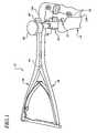
- FIG. 1is an environmental view illustrating a system for performing osteotomies in accordance with the teachings of a preferred embodiment of the present invention to include a first bone plate and a retractor assembly, the first bone plate and the retractor assembly are shown operatively associated with a tibia.
- FIGS. 2A-2Care various views of the first bone plate of the preferred embodiment of the present invention.
- FIG. 3is a front view of a second bone plate of the preferred embodiment of the present invention.
- FIGS. 4A-4Dare various views of the retractor assembly of the preferred embodiment of the present invention.
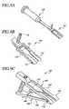
- FIG. 5is a perspective view of an upper handle of the retractor assembly of the preferred embodiment of the present invention.
- FIG. 6is a perspective view of a lower handle of the retractor assembly of the preferred embodiment of the present invention.
- FIGS. 7A-7Dare various views of an upper jaw of the retractor assembly of the preferred embodiment of the present invention.
- FIG. 8is a perspective view of a lower jaw of the retractor assembly of the preferred embodiment of the present invention.
- FIGS. 9A-9Care various views of a retractor assembly constructed in accordance with an alternative embodiment of the present invention.
- the systemis shown to generally include a first bone plate 10 and a retractor assembly 12 .
- the bone plate 10is shown attached to first and second portions 14 a and 14 b of a bone 14 for securing the relative positions between the first and second portions 14 a and 14 b which are separated by a wedge-shaped gap 16 .
- the retractor assembly 12is shown immediately prior to removal from the gap 16 after it has been used by a surgeon to establish a desired dimension for the gap 16 between the first and second bone portions 14 a and 14 b.
- the bone 14is a tibia and the first bone plate 10 is being used to secure the relative positions between the first and second portions 14 a and 14 b for a high tibial osteotomy.
- the teachings of the present inventionare applicable for other surgical procedures in which it is necessary to secure the relative positions between bone portions.
- the first bone plate 10 of the present inventionwill be further described.
- the first bone plate 10is shown to generally include a first or upper mounting portion 18 , a second or lower mounting portion 20 and an intermediate portion 22 .
- the first mounting portion 18is for attachment to the first bone portion 14 a and the second mounting portion 20 is for attachment to the second bone portion 14 b .
- the intermediate portion 22connects the first mounting portion 18 and the second mounting portion 20 .
- the first mounting plate 10is unitarily constructed.
- One suitable materialis titanium alloy. However, those skilled in the art will readily appreciate that other well known materials in the art may be employed.
- the first bone plate 10is shown to include a plurality of mounting apertures 24 each adapted to receive a fastener 25 for securing the bone plate 10 to the bone 14 .
- the first mounting portion 18includes a pair of mounting apertures 24 having centers which are spaced apart from and on opposite sides of a longitudinally extending centerline 26 of the intermediate portion 22 .
- the second mounting portion 20includes a pair of mounting apertures 24 having centers which are spaced apart from an opposite end on opposite sides of the centerline 26 .
- the centers of the mounting apertures 24 of the second mounting portion 20are also spaced apart from one another in a second direction which is generally parallel to the longitudinal centerline 26 .
- first and second mounting portions 18 and 20are shown to be curved in a direction perpendicular to the centerline 26 .
- the spacing of the fasteners 25increases the torsional and compressive stability of the bone plate 10 by spreading out the fasteners 25 .
- the curvature of the mounting portions 18 and 20increases the pullout strength of the first bone plate 10 by accommodating converging fasteners 25 .
- the first and second mounting portions 18 and 20include first and second shelves 28 and 30 , respectively, which extend from a rear surface 32 of the first bone plate 10 .
- the first and second rearwardly extending shelves 28 and 30are both disposed immediately adjacent the intermediate portion 22 and are defined by the intermediate portion which is generally I-shaped.
- the first and second shelves 28 and 30define a flange for engaging the cortical bone of the first and second bone portions 14 a and 14 b , respectively.
- the distance between the first and second shelvesis selected based upon the desired length of the gap.
- the first and second shelves 28 and 30preferably slope anteriorly at an angle of approximately 2°. The anterior slope allows a wider portion of the shelves 28 and 30 to be positioned posteriorly.
- the intermediate portion 22 of the first bone plate 10has a central section with a reduced cross-sectional area.
- a central width of the intermediate portion in a direction perpendicular to the centerline 26is substantially less than the width of the intermediate portion 22 adjacent first mounting portion 18 and adjacent the second mounting portion 22 .
- the central width of the intermediate portion 22is approximately 6 mm.
- the first and second shelves 28 and 30preferably extend the entire width of the intermediate portion 22 adjacent the respective first and second mounting portions 18 and 20 .
- a central section of the intermediate portion 22 and the first and second shelves 28 and 30cooperate to define an I-beam shape.
- the reduced central width of the intermediate portion 22 of the bone plate 10permits improved access to the bone grafting site within the gap 16 . Additionally, the reduced central width of the intermediate portion 22 facilitates placement of the bone plate 10 and compaction of the bone graft (not shown).
- the particular bone plate 10 illustrated in FIGS. 2A-2Cis intended for a high tibial osteotomy of a left tibia. It will be understood by those skilled in the art that the teachings of the present invention are equally applicable for a high tibial osteotomy of the right tibia. In this alternative application, the bone plate 10 would be configured to be a mirror image about the centerline 26 .
- FIG. 3a second bone plate 10 ′ of the system of the present invention is illustrated.
- the second bone plate 10 ′shares various features in common with the first bone plate 10 . For this reason, like reference numerals have been used in FIG. 3 to identify substantially identical elements which have been previously introduced with respect to FIGS. 2A-2C .
- the second bone plate 10 ′is particularly configured for a left high tibial osteotomy. Again, a similar bone plate for a right high tibial osteotomy would have a mirror image about the longitudinally extending centerline 26 .
- the second bone plate 10 ′primarily differs from the first bone plate 10 in the number of mounting apertures 24 provided in each of the first and second mounting portions 18 and 20 . As shown, the first and second mounting portions 18 and 20 include three mounting apertures 24 as opposed to two. It will be appreciated by those skilled in the art that the particular number of mounting apertures 24 may be varied within the scope of the present invention.
- the additional mounting aperture 24 of the first mounting portion 18is shown disposed between the other mounting apertures 24 and is generally centered along the centerline 26 . With respect to the second mounting portion 20 , the additional mounting aperture 24 is located in a downwardly extending segment 34 and has a center positioned laterally between the other two mounting apertures 24 . In the embodiment illustrated, the additional mounting aperture 24 of the second bone plate 10 ′ has a center generally aligned along the centerline 26 .
- the retractor assembly 12is shown to generally include a first or upper handle member 36 and a second or lower handle member 38 .
- the retractor assembly 12is further shown to generally include a first or upper jaw member 40 and a second or lower jaw member 42 .
- the second handle member 38is coupled to the first handle member 36 for relative movement about a first pivot axis 44 .
- the first jaw member 40has a first end 46 coupled to a first end 48 of the first handle member 36 .
- the second jaw member 42has a first end 50 coupled to a first end 52 of the second handle member 38 .
- the second jaw member 42includes a second end 54 pivotally coupled to a second end 56 of the first jaw member 40 for relative movement about a second pivot axis 58 .
- the second pivot axis 58is generally perpendicular to the first pivot axis 44 .
- the first end 46 of the first jaw 40is illustrated to define a cavity 58 .
- the cavity 58adjustably receives a ball 60 attached to and extending from the first end 48 of the first arm 36 .
- the first end 50 of the second jaw 42defines a cavity 59 receiving a ball 60 extending from the first end 52 of the second arm 38 .
- the joints defined between the balls 60 and their respective cavities 59accommodate relative rotation between the first and second jaws 40 and 42 and the first and second arms 36 and 38 about axes passing through the respective ball 60 and generally parallel to the second axis 58 .
- the retractor assembly 12is further illustrated to include a coupling member 62 for maintaining a selected orientation between the first and second jaws 40 and 42 by maintaining a selected orientation between the first and second arms 36 and 38 .
- the coupling member 62is attached to a second end 64 of the first handle member 36 and releasably engageable with a second end 66 of the second handle member 38 .
- the coupling member 62is pivotally attached to the second end 64 of the first handle member 36 for articulation about a pivot pin 68 .
- the coupling member 62is formed to include a plurality of ratchet teeth 70 along its length for engaging the second end 66 of the second handle 38 and preferably includes indicia indicative of a size of the gap 16 when the first and second jaws 40 and 42 are fully inserted into a cut between the first and second bone portions 14 a and 14 b .
- the indiciais shown particularly in FIG. 4D .
- the retractor assembly 12further includes a biasing arrangement 72 coupled to the first and second handle members 36 and operative for biasing the first and second jaw members 40 and 42 to a first position in which the first and second jaw members 40 and 42 are generally located in a common plane.
- the first positionis illustrated in FIG. 4 b .
- the biasing arrangement 72is illustrated to include first and second spring members 74 and 76 .
- the first spring member 74is connected at one end to the first handle member 36 .
- the second spring member 76is similarly mounted at one end to the second handle member 38 .
- One of the spring members 74includes a slot 78 at its free end which receives the free end of the other spring member 76 .
- the spring member 74 and 76are arranged with the handle members 36 and 38 , respectively, to provide a spring biasing arrangement for biasing the handle members 36 and 38 away from one another.
- first and second jaws 40 and 42 of the retractor assembly 12are inserted into a cut between the first and second bone portions 14 a and 14 b while the first and second jaws 40 and 42 are substantially coplanar.
- the first and second jaws 40 and 42are inserted to a depth of approximately 35 mm.
- the first ends 48 and 52 of the first and second handle members 36 and 38both include a semicylindrical portion 80 .
- Semicylindrical portions 80cooperate to define a cylinder having a reduced width circumferential groove 82 .
- a cap 84defines a cylindrical aperture receiving the portions 80 .
- the cap 84is secured to the retractor assembly 12 through a thumb screw 86 and provides a surface for striking with a hammer during introduction of the jaws 40 and 42 into the bone 14 .
- a triangular shaped wedgeis opened between the first and second bone portions 14 a and 14 b with the retractor assembly 12 through manual squeezing of the first end second handle members 36 and 38 .
- the manual squeezing of the first and second handle members 36 and 38overcomes the biasing force provided by the biasing arrangement 72 and urges the first end 48 of the first handle member 36 apart from the first end 52 of the second handle member 38 .
- the first end 46 of the first jaw member and the first end 50 of the second jaw member 42are urged apart through relative rotation about the second pivot axis 58 to a second position.
- the second positionis shown, for example, in FIG. 4A .
- the surgeonopens the gap in the bone 14 to a desired dimension.
- the gap 16 and the bone 14corresponds in size to the indicia on the coupling member 62 located adjacent the second end 66 of the second handle member 38 based on complete insertion of the jaws 40 and 42 .
- the configuration of and relative movement between the jaws 40 and 42permit improved bone plate placement and anatomic limb alignment.
- the bone plate 10 or 10 ′is secured in place with the fasteners 25 and the coupling member 62 may be disengaged from the second end 66 of the second handle 38 .
- the biasing force of the biasing arrangement 72returns the first and second jaws 40 and 42 to their generally coplanar orientation. At this point the jaws 40 and 42 may be removed from the gap 16 .
- the gap 16is spanned only by the reduced width central portion of the intermediate portion 22 . As such, improved access to the bone grafting site is provided.
- FIGS. 9A-9Ca retractor assembly 102 constructed in accordance with the teachings of an alternative embodiment of the present invention is illustrated.
- the retractor assemblyis shown to include an upper jaw 104 and a lower jaw 106 .
- the lower jaw 106includes a pair of spaced apart arms 108 and the upper jaw similarly includes a pair of spaced apart arms 110 .
- Forward ends of the arms 108 of the lower jaw 106are coupled to an associated one of the arms 110 of the upper jaw 104 by a pin 112 .
- the pins 112define an axis about which the upper and lower jaws 104 and 106 relatively articulate between an open position and a closed position.
- the open positionis shown in FIG. 9C and the closed position is shown in FIG. 9B .
- the retractor assembly 102is further shown to include a drive member 114 which threadably engages an aperture (not specifically shown) in an end of the upper jaw 104 .
- Rotation of the drive member 14 in a first directioncauses the drive member to extend below the upper jaw 104 and engage an end of the lower jaw 106 .
- the jaws 104 and 106are articulated between the closed and open positions.
- the retractor assembly 102is shown in FIG. 9A engaged with a handle assembly 116 .
- the handle assemblyreleasably engages the upper jaw 104 and provides a striking surface for introducing the retractor assembly 102 into a bone opening.
- the handle assembly 116may releasably engage the retractor assembly in any manner well known in the art.
- the handle assemblymay engage an aperture or slot defined by the upper jaw 104 .
- the handle assembly 116can threadably engage the retractor assembly 102 .
Landscapes
- Health & Medical Sciences (AREA)
- Surgery (AREA)
- Orthopedic Medicine & Surgery (AREA)
- Life Sciences & Earth Sciences (AREA)
- Heart & Thoracic Surgery (AREA)
- Nuclear Medicine, Radiotherapy & Molecular Imaging (AREA)
- Engineering & Computer Science (AREA)
- Biomedical Technology (AREA)
- Medical Informatics (AREA)
- Molecular Biology (AREA)
- Animal Behavior & Ethology (AREA)
- General Health & Medical Sciences (AREA)
- Public Health (AREA)
- Veterinary Medicine (AREA)
- Neurology (AREA)
- Surgical Instruments (AREA)
Abstract
Description
Claims (22)
Priority Applications (1)
| Application Number | Priority Date | Filing Date | Title |
|---|---|---|---|
| US10/440,613US7326218B2 (en) | 2001-03-14 | 2003-05-19 | Bone plate and retractor assembly |
Applications Claiming Priority (2)
| Application Number | Priority Date | Filing Date | Title |
|---|---|---|---|
| US09/808,260US6565570B2 (en) | 2001-03-14 | 2001-03-14 | Bone plate and retractor assembly |
| US10/440,613US7326218B2 (en) | 2001-03-14 | 2003-05-19 | Bone plate and retractor assembly |
Related Parent Applications (1)
| Application Number | Title | Priority Date | Filing Date |
|---|---|---|---|
| US09/808,260ContinuationUS6565570B2 (en) | 2001-03-14 | 2001-03-14 | Bone plate and retractor assembly |
Publications (2)
| Publication Number | Publication Date |
|---|---|
| US20030195516A1 US20030195516A1 (en) | 2003-10-16 |
| US7326218B2true US7326218B2 (en) | 2008-02-05 |
Family
ID=25198302
Family Applications (2)
| Application Number | Title | Priority Date | Filing Date |
|---|---|---|---|
| US09/808,260Expired - LifetimeUS6565570B2 (en) | 2001-03-14 | 2001-03-14 | Bone plate and retractor assembly |
| US10/440,613Expired - Fee RelatedUS7326218B2 (en) | 2001-03-14 | 2003-05-19 | Bone plate and retractor assembly |
Family Applications Before (1)
| Application Number | Title | Priority Date | Filing Date |
|---|---|---|---|
| US09/808,260Expired - LifetimeUS6565570B2 (en) | 2001-03-14 | 2001-03-14 | Bone plate and retractor assembly |
Country Status (5)
| Country | Link |
|---|---|
| US (2) | US6565570B2 (en) |
| EP (1) | EP1377241A2 (en) |
| JP (1) | JP4468635B2 (en) |
| AU (1) | AU2002248608A1 (en) |
| WO (1) | WO2002071924A2 (en) |
Cited By (7)
| Publication number | Priority date | Publication date | Assignee | Title |
|---|---|---|---|---|
| US20050177173A1 (en)* | 1998-10-02 | 2005-08-11 | Max Aebi | Spinal disc space distractor |
| US20100016858A1 (en)* | 2008-07-21 | 2010-01-21 | Gerlinde Michel | Carbon Fiber Reinforced Peek Bone Plate With Titanium Fixation Screws |
| US20110046681A1 (en)* | 2008-10-02 | 2011-02-24 | Bernard Prandi | Orthopedic implant in the form of a plate to be fixed between two bone parts |
| US8740915B2 (en) | 2010-04-27 | 2014-06-03 | DePuy Synthes Products, LLC | Bone fixation systems and methods of use |
| US8936615B2 (en) | 2010-04-27 | 2015-01-20 | DePuy Synthes Products, LLC | Bone fixation system including K-wire compression |
| US10617457B2 (en) | 2016-03-03 | 2020-04-14 | Stryker European Holdings I, Llc | Forceps for handling/holding a mobile wedge plate |
| US20210251659A1 (en)* | 2017-02-26 | 2021-08-19 | Treace Medical Concepts, Inc. | Fulcrum for tarsal-metatarsal joint procedure |
Families Citing this family (194)
| Publication number | Priority date | Publication date | Assignee | Title |
|---|---|---|---|---|
| US7201751B2 (en)* | 1997-01-02 | 2007-04-10 | St. Francis Medical Technologies, Inc. | Supplemental spine fixation device |
| US7101375B2 (en) | 1997-01-02 | 2006-09-05 | St. Francis Medical Technologies, Inc. | Spine distraction implant |
| US6902566B2 (en) | 1997-01-02 | 2005-06-07 | St. Francis Medical Technologies, Inc. | Spinal implants, insertion instruments, and methods of use |
| US7306628B2 (en) | 2002-10-29 | 2007-12-11 | St. Francis Medical Technologies | Interspinous process apparatus and method with a selectably expandable spacer |
| US20080039859A1 (en)* | 1997-01-02 | 2008-02-14 | Zucherman James F | Spine distraction implant and method |
| US7959652B2 (en) | 2005-04-18 | 2011-06-14 | Kyphon Sarl | Interspinous process implant having deployable wings and method of implantation |
| US20020143331A1 (en)* | 1998-10-20 | 2002-10-03 | Zucherman James F. | Inter-spinous process implant and method with deformable spacer |
| US6712819B2 (en) | 1998-10-20 | 2004-03-30 | St. Francis Medical Technologies, Inc. | Mating insertion instruments for spinal implants and methods of use |
| US6068630A (en) | 1997-01-02 | 2000-05-30 | St. Francis Medical Technologies, Inc. | Spine distraction implant |
| US20080027552A1 (en)* | 1997-01-02 | 2008-01-31 | Zucherman James F | Spine distraction implant and method |
| US7189234B2 (en)* | 1998-10-20 | 2007-03-13 | St. Francis Medical Technologies, Inc. | Interspinous process implant sizer and distractor with a split head and size indicator and method |
| US7029473B2 (en)* | 1998-10-20 | 2006-04-18 | St. Francis Medical Technologies, Inc. | Deflectable spacer for use as an interspinous process implant and method |
| US8231662B2 (en)* | 2006-10-17 | 2012-07-31 | Acumed Llc | Bone fixation with a strut-stabilized bone plate |
| US20050240187A1 (en) | 2004-04-22 | 2005-10-27 | Huebner Randall J | Expanded fixation of bones |
| US7326212B2 (en) | 2002-11-19 | 2008-02-05 | Acumed Llc | Bone plates with reference marks |
| US7717945B2 (en) | 2002-07-22 | 2010-05-18 | Acumed Llc | Orthopedic systems |
| US7537604B2 (en) | 2002-11-19 | 2009-05-26 | Acumed Llc | Bone plates with slots |
| US20050065521A1 (en)* | 2002-02-22 | 2005-03-24 | Steger Shon D. | Method and apparatus for bone fracture fixation |
| CN1309352C (en) | 2002-07-22 | 2007-04-11 | 精密医疗责任有限公司 | Bone fusion system |
| US6966929B2 (en) | 2002-10-29 | 2005-11-22 | St. Francis Medical Technologies, Inc. | Artificial vertebral disk replacement implant with a spacer |
| US7833246B2 (en) | 2002-10-29 | 2010-11-16 | Kyphon SÀRL | Interspinous process and sacrum implant and method |
| US8070778B2 (en) | 2003-05-22 | 2011-12-06 | Kyphon Sarl | Interspinous process implant with slide-in distraction piece and method of implantation |
| US7083649B2 (en) | 2002-10-29 | 2006-08-01 | St. Francis Medical Technologies, Inc. | Artificial vertebral disk replacement implant with translating pivot point |
| US7931674B2 (en) | 2005-03-21 | 2011-04-26 | Kyphon Sarl | Interspinous process implant having deployable wing and method of implantation |
| US7909853B2 (en)* | 2004-09-23 | 2011-03-22 | Kyphon Sarl | Interspinous process implant including a binder and method of implantation |
| US7273496B2 (en) | 2002-10-29 | 2007-09-25 | St. Francis Medical Technologies, Inc. | Artificial vertebral disk replacement implant with crossbar spacer and method |
| US7549999B2 (en) | 2003-05-22 | 2009-06-23 | Kyphon Sarl | Interspinous process distraction implant and method of implantation |
| US8048117B2 (en) | 2003-05-22 | 2011-11-01 | Kyphon Sarl | Interspinous process implant and method of implantation |
| US7497859B2 (en)* | 2002-10-29 | 2009-03-03 | Kyphon Sarl | Tools for implanting an artificial vertebral disk |
| AU2003294414B2 (en)* | 2002-11-19 | 2009-03-12 | Acumed Llc | Deformable bone plates |
| AU2003294342A1 (en) | 2002-11-19 | 2004-06-15 | Acumed Llc | Guide system for bone-repair devices |
| US7811312B2 (en)* | 2002-12-04 | 2010-10-12 | Morphographics, Lc | Bone alignment implant and method of use |
| US7335203B2 (en) | 2003-02-12 | 2008-02-26 | Kyphon Inc. | System and method for immobilizing adjacent spinous processes |
| WO2004112587A2 (en) | 2003-06-20 | 2004-12-29 | Acumed Llc | Bone plates with intraoperatively tapped apertures |
| US7635365B2 (en) | 2003-08-28 | 2009-12-22 | Ellis Thomas J | Bone plates |
| US7520899B2 (en) | 2003-11-05 | 2009-04-21 | Kyphon Sarl | Laterally insertable artificial vertebral disk replacement implant with crossbar spacer |
| US7670377B2 (en) | 2003-11-21 | 2010-03-02 | Kyphon Sarl | Laterally insertable artifical vertebral disk replacement implant with curved spacer |
| US20050154462A1 (en) | 2003-12-02 | 2005-07-14 | St. Francis Medical Technologies, Inc. | Laterally insertable artificial vertebral disk replacement implant with translating pivot point |
| US7481839B2 (en) | 2003-12-02 | 2009-01-27 | Kyphon Sarl | Bioresorbable interspinous process implant for use with intervertebral disk remediation or replacement implants and procedures |
| WO2005102193A2 (en) | 2004-04-19 | 2005-11-03 | Acumed, Llc | Placement of fasteners into bone |
| US7524324B2 (en) | 2004-04-28 | 2009-04-28 | Kyphon Sarl | System and method for an interspinous process implant as a supplement to a spine stabilization implant |
| US8083746B2 (en)* | 2004-05-07 | 2011-12-27 | Arthrex, Inc. | Open wedge osteotomy system and surgical method |
| US8753348B2 (en) | 2004-07-02 | 2014-06-17 | DePuy Synthes Products, LLC | Compressor-distractor |
| US8012209B2 (en) | 2004-09-23 | 2011-09-06 | Kyphon Sarl | Interspinous process implant including a binder, binder aligner and method of implantation |
| US7575600B2 (en) | 2004-09-29 | 2009-08-18 | Kyphon Sarl | Artificial vertebral disk replacement implant with translating articulation contact surface and method |
| US7481840B2 (en) | 2004-09-29 | 2009-01-27 | Kyphon Sarl | Multi-piece artificial spinal disk replacement device with selectably positioning articulating element |
| US8167944B2 (en) | 2004-10-20 | 2012-05-01 | The Board Of Trustees Of The Leland Stanford Junior University | Systems and methods for posterior dynamic stabilization of the spine |
| US8945183B2 (en) | 2004-10-20 | 2015-02-03 | Vertiflex, Inc. | Interspinous process spacer instrument system with deployment indicator |
| US9119680B2 (en) | 2004-10-20 | 2015-09-01 | Vertiflex, Inc. | Interspinous spacer |
| US8128662B2 (en) | 2004-10-20 | 2012-03-06 | Vertiflex, Inc. | Minimally invasive tooling for delivery of interspinous spacer |
| US8409282B2 (en) | 2004-10-20 | 2013-04-02 | Vertiflex, Inc. | Systems and methods for posterior dynamic stabilization of the spine |
| US9023084B2 (en) | 2004-10-20 | 2015-05-05 | The Board Of Trustees Of The Leland Stanford Junior University | Systems and methods for stabilizing the motion or adjusting the position of the spine |
| US8425559B2 (en) | 2004-10-20 | 2013-04-23 | Vertiflex, Inc. | Systems and methods for posterior dynamic stabilization of the spine |
| US8012207B2 (en) | 2004-10-20 | 2011-09-06 | Vertiflex, Inc. | Systems and methods for posterior dynamic stabilization of the spine |
| US8152837B2 (en) | 2004-10-20 | 2012-04-10 | The Board Of Trustees Of The Leland Stanford Junior University | Systems and methods for posterior dynamic stabilization of the spine |
| US8613747B2 (en) | 2004-10-20 | 2013-12-24 | Vertiflex, Inc. | Spacer insertion instrument |
| US8273108B2 (en) | 2004-10-20 | 2012-09-25 | Vertiflex, Inc. | Interspinous spacer |
| US9161783B2 (en) | 2004-10-20 | 2015-10-20 | Vertiflex, Inc. | Interspinous spacer |
| US7763074B2 (en) | 2004-10-20 | 2010-07-27 | The Board Of Trustees Of The Leland Stanford Junior University | Systems and methods for posterior dynamic stabilization of the spine |
| US8277488B2 (en) | 2004-10-20 | 2012-10-02 | Vertiflex, Inc. | Interspinous spacer |
| US8123807B2 (en)* | 2004-10-20 | 2012-02-28 | Vertiflex, Inc. | Systems and methods for posterior dynamic stabilization of the spine |
| US8123782B2 (en)* | 2004-10-20 | 2012-02-28 | Vertiflex, Inc. | Interspinous spacer |
| US8317864B2 (en) | 2004-10-20 | 2012-11-27 | The Board Of Trustees Of The Leland Stanford Junior University | Systems and methods for posterior dynamic stabilization of the spine |
| US20060089651A1 (en)* | 2004-10-26 | 2006-04-27 | Trudeau Jeffrey L | Apparatus and method for anchoring a surgical rod |
| EP2219538B1 (en) | 2004-12-06 | 2022-07-06 | Vertiflex, Inc. | Spacer insertion instrument |
| US7763050B2 (en) | 2004-12-13 | 2010-07-27 | Warsaw Orthopedic, Inc. | Inter-cervical facet implant with locking screw and method |
| US7776090B2 (en) | 2004-12-13 | 2010-08-17 | Warsaw Orthopedic, Inc. | Inter-cervical facet implant and method |
| US8029540B2 (en) | 2005-05-10 | 2011-10-04 | Kyphon Sarl | Inter-cervical facet implant with implantation tool |
| US8118848B2 (en) | 2005-01-28 | 2012-02-21 | Orthohelix Surgical Designs, Inc. | Orthopedic plate for use in fibula repair |
| US7799061B2 (en)* | 2005-01-28 | 2010-09-21 | Orthohelix Surgical Designs, Inc. | Orthopedic plate |
| US8118846B2 (en) | 2005-01-28 | 2012-02-21 | Orthohelix Surgical Designs, Inc. | Orthopedic plates for use in clavicle repair and methods for their use |
| US8540777B2 (en)* | 2005-01-31 | 2013-09-24 | Arthrex, Inc. | Method and apparatus for performing an open wedge, high tibial osteotomy |
| WO2008016687A2 (en)* | 2006-08-02 | 2008-02-07 | Ibalance Medical, Inc. | Method and apparatus for performing a high tibial, dome osteotomy |
| US7935119B2 (en) | 2005-01-31 | 2011-05-03 | Ibalance Medical, Inc. | Method for performing an open wedge, high tibial osteotomy |
| US8771279B2 (en) | 2005-01-31 | 2014-07-08 | Arthrex, Inc. | Method and apparatus for performing an osteotomy in bone |
| US8496662B2 (en)* | 2005-01-31 | 2013-07-30 | Arthrex, Inc. | Method and apparatus for forming a wedge-like opening in a bone for an open wedge osteotomy |
| US7967823B2 (en)* | 2005-01-31 | 2011-06-28 | Arthrex, Inc. | Method and apparatus for performing an open wedge, high tibial osteotomy |
| US8906026B2 (en) | 2005-01-31 | 2014-12-09 | Arthrex, Inc. | Method and apparatus for performing an open wedge, high tibial osteotomy |
| CA2597228C (en)* | 2005-02-09 | 2014-07-22 | Ibalance Medical, Inc. | Multi-part implant for open wedge knee osteotomies |
| US7927354B2 (en)* | 2005-02-17 | 2011-04-19 | Kyphon Sarl | Percutaneous spinal implants and methods |
| US8029567B2 (en) | 2005-02-17 | 2011-10-04 | Kyphon Sarl | Percutaneous spinal implants and methods |
| US8096995B2 (en)* | 2005-02-17 | 2012-01-17 | Kyphon Sarl | Percutaneous spinal implants and methods |
| US8092459B2 (en)* | 2005-02-17 | 2012-01-10 | Kyphon Sarl | Percutaneous spinal implants and methods |
| US20070276373A1 (en)* | 2005-02-17 | 2007-11-29 | Malandain Hugues F | Percutaneous Spinal Implants and Methods |
| US8096994B2 (en) | 2005-02-17 | 2012-01-17 | Kyphon Sarl | Percutaneous spinal implants and methods |
| US8034080B2 (en)* | 2005-02-17 | 2011-10-11 | Kyphon Sarl | Percutaneous spinal implants and methods |
| US7998208B2 (en)* | 2005-02-17 | 2011-08-16 | Kyphon Sarl | Percutaneous spinal implants and methods |
| US7993342B2 (en) | 2005-02-17 | 2011-08-09 | Kyphon Sarl | Percutaneous spinal implants and methods |
| US20060184248A1 (en)* | 2005-02-17 | 2006-08-17 | Edidin Avram A | Percutaneous spinal implants and methods |
| JP2006253316A (en)* | 2005-03-09 | 2006-09-21 | Sony Corp | Solid-state imaging device |
| US20060235403A1 (en)* | 2005-03-17 | 2006-10-19 | Jason Blain | Flanged interbody fusion device with locking plate |
| US7931680B2 (en)* | 2005-03-31 | 2011-04-26 | Depuy Products, Inc. | Plate for lengthening the lateral column of the foot |
| CA2603400C (en) | 2005-04-01 | 2015-11-24 | Ibalance Medical, Inc. | Method and apparatus for performing an open wedge, high tibial osteotomy |
| GB0510111D0 (en)* | 2005-05-18 | 2005-06-22 | Photonics The | Patellar resection tool |
| US20070010818A1 (en)* | 2005-07-06 | 2007-01-11 | Stone Howard A | Surgical system for joints |
| GB0519832D0 (en)* | 2005-09-30 | 2005-11-09 | Depuy Int Ltd | Instrument assembly for use in knee joint replacement surgery |
| GB0519829D0 (en)* | 2005-09-30 | 2005-11-09 | Depuy Int Ltd | Distractor instrument |
| US7985246B2 (en)* | 2006-03-31 | 2011-07-26 | Warsaw Orthopedic, Inc. | Methods and instruments for delivering interspinous process spacers |
| US8241292B2 (en) | 2006-06-30 | 2012-08-14 | Howmedica Osteonics Corp. | High tibial osteotomy system |
| JP4736091B2 (en)* | 2006-06-30 | 2011-07-27 | オリンパステルモバイオマテリアル株式会社 | Osteotomy opener |
| WO2008019049A2 (en)* | 2006-08-03 | 2008-02-14 | Ibalance Medical Inc. | Method and apparatus for performing an open wedge, high tibial osteotomy |
| USD568470S1 (en)* | 2006-09-13 | 2008-05-06 | Karl Storz Gmbh & Co. Kg | Medical instrument |
| WO2008039508A2 (en) | 2006-09-27 | 2008-04-03 | Ibalance Medical, Inc. | Method and apparatus for performing an open wedge, high tibial osteotomy |
| US8845726B2 (en) | 2006-10-18 | 2014-09-30 | Vertiflex, Inc. | Dilator |
| US20080177298A1 (en)* | 2006-10-24 | 2008-07-24 | St. Francis Medical Technologies, Inc. | Tensioner Tool and Method for Implanting an Interspinous Process Implant Including a Binder |
| US8409209B2 (en)* | 2006-11-22 | 2013-04-02 | Arthrex, Inc. | Method and apparatus for performing an open wedge, high tibial osteotomy |
| US20080208197A1 (en)* | 2006-11-30 | 2008-08-28 | Kelly Ammann | Method and apparatus for performing an open wedge, high tibial osteotomy |
| WO2008070027A2 (en)* | 2006-12-01 | 2008-06-12 | Ibalance Medical, Inc. | Method and apparatus for performing an open wedge, low femoral osteotomy |
| US7955392B2 (en) | 2006-12-14 | 2011-06-07 | Warsaw Orthopedic, Inc. | Interspinous process devices and methods |
| US9039768B2 (en) | 2006-12-22 | 2015-05-26 | Medos International Sarl | Composite vertebral spacers and instrument |
| US20080195099A1 (en)* | 2007-02-13 | 2008-08-14 | The Brigham And Women's Hospital, Inc. | Osteotomy system |
| US8308774B2 (en) | 2007-02-14 | 2012-11-13 | Pioneer Surgical Technology, Inc. | Spinal rod reducer and cap insertion apparatus |
| US20080234689A1 (en)* | 2007-02-21 | 2008-09-25 | Warsaw Orthopedic, Inc. | Vertebral Plate Measuring Device and Method of Use |
| US8092488B2 (en)* | 2007-03-30 | 2012-01-10 | Dinucci Kent | Bone retractor tool |
| AU2008241447B2 (en) | 2007-04-16 | 2014-03-27 | Vertiflex, Inc. | Interspinous spacer |
| US8926618B2 (en) | 2007-04-19 | 2015-01-06 | Howmedica Osteonics Corp. | Cutting guide with internal distraction |
| US8435244B2 (en) | 2007-05-02 | 2013-05-07 | Zimmer, Inc. | Orthopedic tool for altering the connection between orthopedic components |
| US8486081B2 (en) | 2007-07-23 | 2013-07-16 | DePuy Synthes Products, LLC | Implant insertion device and method |
| CA2698718C (en)* | 2007-09-07 | 2015-10-06 | Vertiflex, Inc. | Interspinous spacer |
| AU2009206098B2 (en) | 2008-01-15 | 2014-10-30 | Vertiflex, Inc. | Interspinous spacer |
| US8235997B2 (en) | 2008-01-29 | 2012-08-07 | Pioneer Surgical Technology, Inc. | Rod locking instrument |
| US20090198241A1 (en)* | 2008-02-04 | 2009-08-06 | Phan Christopher U | Spine distraction tools and methods of use |
| US20090248092A1 (en) | 2008-03-26 | 2009-10-01 | Jonathan Bellas | Posterior Intervertebral Disc Inserter and Expansion Techniques |
| RU2503093C2 (en)* | 2008-06-10 | 2013-12-27 | Конинклейке Филипс Электроникс Н.В. | Led module |
| US8623062B2 (en)* | 2008-09-29 | 2014-01-07 | Dimitriy G. Kondrashov | System and method to stablize a spinal column including a spinolaminar locking plate |
| US8192441B2 (en)* | 2008-10-03 | 2012-06-05 | Howmedica Osteonics Corp. | High tibial osteotomy instrumentation |
| US9237910B2 (en) | 2012-01-26 | 2016-01-19 | Acute Innovations Llc | Clip for rib stabilization |
| US12285197B2 (en) | 2008-10-10 | 2025-04-29 | Acumed Llc | Bone fixation system with opposed mounting portions |
| US8114131B2 (en) | 2008-11-05 | 2012-02-14 | Kyphon Sarl | Extension limiting devices and methods of use for the spine |
| US20100168799A1 (en)* | 2008-12-29 | 2010-07-01 | Schumer Evan D | Ulnar osteotomy plate including increased compression |
| US9220547B2 (en) | 2009-03-27 | 2015-12-29 | Spinal Elements, Inc. | Flanged interbody fusion device |
| US9526620B2 (en)* | 2009-03-30 | 2016-12-27 | DePuy Synthes Products, Inc. | Zero profile spinal fusion cage |
| US8551023B2 (en) | 2009-03-31 | 2013-10-08 | Depuy (Ireland) | Device and method for determining force of a knee joint |
| US8740817B2 (en) | 2009-03-31 | 2014-06-03 | Depuy (Ireland) | Device and method for determining forces of a patient's joint |
| US8597210B2 (en) | 2009-03-31 | 2013-12-03 | Depuy (Ireland) | System and method for displaying joint force data |
| US8721568B2 (en) | 2009-03-31 | 2014-05-13 | Depuy (Ireland) | Method for performing an orthopaedic surgical procedure |
| US20100286701A1 (en)* | 2009-05-08 | 2010-11-11 | Kyphon Sarl | Distraction tool for distracting an interspinous space |
| US8986353B2 (en) | 2009-07-09 | 2015-03-24 | Orthohelix Surgical Designs, Inc. | Osteotomy plate, plate driver and method for their use |
| WO2011017321A2 (en)* | 2009-08-04 | 2011-02-10 | University Of South Florida | Apparatus for osteotomy and graft preparation |
| EP2289440B1 (en)* | 2009-08-27 | 2013-05-29 | Stryker Leibinger GmbH & Co. KG | Bone anchor, orthopaedic device and orthopaedic system |
| US9393129B2 (en) | 2009-12-10 | 2016-07-19 | DePuy Synthes Products, Inc. | Bellows-like expandable interbody fusion cage |
| US8740948B2 (en) | 2009-12-15 | 2014-06-03 | Vertiflex, Inc. | Spinal spacer for cervical and other vertebra, and associated systems and methods |
| US8568417B2 (en) | 2009-12-18 | 2013-10-29 | Charles River Engineering Solutions And Technologies, Llc | Articulating tool and methods of using |
| US8900240B2 (en)* | 2010-02-12 | 2014-12-02 | Pioneer Surgical Technology, Inc. | Spinal rod and screw securing apparatus and method |
| US8147526B2 (en) | 2010-02-26 | 2012-04-03 | Kyphon Sarl | Interspinous process spacer diagnostic parallel balloon catheter and methods of use |
| US11529241B2 (en) | 2010-09-23 | 2022-12-20 | DePuy Synthes Products, Inc. | Fusion cage with in-line single piece fixation |
| US20120078372A1 (en) | 2010-09-23 | 2012-03-29 | Thomas Gamache | Novel implant inserter having a laterally-extending dovetail engagement feature |
| US20120078373A1 (en) | 2010-09-23 | 2012-03-29 | Thomas Gamache | Stand alone intervertebral fusion device |
| US8747410B2 (en)* | 2010-10-26 | 2014-06-10 | Zimmer, Inc. | Patellar resection instrument with variable depth guide |
| GB201115411D0 (en) | 2011-09-07 | 2011-10-19 | Depuy Ireland | Surgical instrument |
| US9248028B2 (en) | 2011-09-16 | 2016-02-02 | DePuy Synthes Products, Inc. | Removable, bone-securing cover plate for intervertebral fusion cage |
| WO2013049849A2 (en) | 2011-09-30 | 2013-04-04 | Acute Innovations, Llc, An Oregon Limited Liability Company | Bone fixation system with opposed mounting portions |
| US8790378B2 (en) | 2012-02-02 | 2014-07-29 | Biomet C.V. | Distal radius fracture fixation plate with integrated and adjustable volar ulnar facet support |
| US9271836B2 (en) | 2012-03-06 | 2016-03-01 | DePuy Synthes Products, Inc. | Nubbed plate |
| US9381011B2 (en) | 2012-03-29 | 2016-07-05 | Depuy (Ireland) | Orthopedic surgical instrument for knee surgery |
| US10206792B2 (en) | 2012-03-31 | 2019-02-19 | Depuy Ireland Unlimited Company | Orthopaedic surgical system for determining joint forces of a patients knee joint |
| US10070973B2 (en) | 2012-03-31 | 2018-09-11 | Depuy Ireland Unlimited Company | Orthopaedic sensor module and system for determining joint forces of a patient's knee joint |
| US10182921B2 (en) | 2012-11-09 | 2019-01-22 | DePuy Synthes Products, Inc. | Interbody device with opening to allow packing graft and other biologics |
| US9668786B2 (en)* | 2012-11-16 | 2017-06-06 | Southern Spine, Llc | Linkage systems for interspinous process spacing device |
| US9949773B2 (en)* | 2012-12-28 | 2018-04-24 | Paragon 28, Inc. | Orthopedic bone plate and locking tab apparatus and method of use |
| EP2976024B1 (en)* | 2013-03-18 | 2017-05-10 | Claes, Antoon | Surgical device for proper orientation during osteotomy |
| WO2014147604A2 (en)* | 2013-03-19 | 2014-09-25 | Quadrante Do Futuro, Unipessoal Lda | Dynamic osteotomy plate including devices, apparatus and methods using such a plate |
| US9820759B1 (en)* | 2013-05-20 | 2017-11-21 | Ascension Orthopedics, Inc. | Drill guide for use in bone fixation |
| TR201809866T4 (en)* | 2013-11-03 | 2018-07-23 | Ignite Concepts Gmbh | Osteotomy implant. |
| GB2525593A (en)* | 2014-04-25 | 2015-11-04 | Fusion Implants Ltd | Combined bone cutting guide and spreader device |
| AU2015256024B2 (en) | 2014-05-07 | 2020-03-05 | Vertiflex, Inc. | Spinal nerve decompression systems, dilation systems, and methods of using the same |
| EP3164093B1 (en) | 2014-07-03 | 2024-02-14 | Acumed LLC | Bone plate with movable joint |
| US9730686B2 (en) | 2014-09-03 | 2017-08-15 | Biomet C.V. | System and method of soft tissue anchoring to metaphyseal bone plate |
| TWI680741B (en)* | 2014-10-23 | 2020-01-01 | 麗歐醫療公司 | Osteotomy implant |
| US10448981B2 (en)* | 2015-01-08 | 2019-10-22 | Neutin Orthopedics, LLC | Fixed bone plate for rotational and translational first metatarsal osteotomy procedures |
| AU2016212009C1 (en) | 2015-01-27 | 2021-02-25 | Spinal Elements, Inc. | Facet joint implant |
| AU2016298060B2 (en)* | 2015-07-27 | 2021-04-01 | Hip Innovation Technology, LLC | Tool and method for separating a femoral cup from an acetabular ball in an implanted hip prosthesis |
| US10376296B2 (en)* | 2016-08-23 | 2019-08-13 | Biomet Manufacturing, Llc | Adjustable wedge implants |
| US11439451B2 (en) | 2017-06-23 | 2022-09-13 | Orthopediatrics Corp. | Insertion apparatus for an intramedullary nail |
| US10940016B2 (en) | 2017-07-05 | 2021-03-09 | Medos International Sarl | Expandable intervertebral fusion cage |
| USD894385S1 (en) | 2017-10-27 | 2020-08-25 | Orthopediatrics Corp. | Orthopedic tool |
| US11678894B2 (en) | 2017-12-15 | 2023-06-20 | Jonathan P. Cabot | Knee balancing instrument |
| US11266449B2 (en) | 2017-12-19 | 2022-03-08 | Orthopediatrics Corp | Osteotomy device and methods |
| US11241263B1 (en)* | 2018-03-06 | 2022-02-08 | William E. Nordt, III | Bone plate apparatus with articulating joints |
| JP7265327B2 (en)* | 2018-08-24 | 2023-04-26 | オリンパステルモバイオマテリアル株式会社 | Bone dilatation devices and bone dilatation systems |
| US11154289B2 (en)* | 2018-08-24 | 2021-10-26 | Buxton BioMedical, Inc. | Bone distractor |
| AU2019342137A1 (en) | 2018-09-20 | 2021-03-25 | Spinal Elements, Inc. | Spinal implant device |
| KR102158669B1 (en)* | 2018-11-05 | 2020-09-22 | 인제대학교 산학협력단 | Spreader for high tibial osteotomy |
| TW202031202A (en) | 2018-12-27 | 2020-09-01 | 日商可樂麗股份有限公司 | Spreader |
| CN111904584B (en)* | 2020-08-31 | 2024-07-23 | 中国人民解放军联勤保障部队第九〇九医院 | Overstretching type tibia plateau fracture reduction forceps |
| US11911284B2 (en) | 2020-11-19 | 2024-02-27 | Spinal Elements, Inc. | Curved expandable interbody devices and deployment tools |
| WO2022133456A1 (en) | 2020-12-17 | 2022-06-23 | Spinal Elements, Inc. | Spinal implant device |
| JP6999852B1 (en) | 2021-06-29 | 2022-01-19 | HOYA Technosurgical株式会社 | Bone opener for osteotomy |
| WO2023158581A1 (en) | 2022-02-15 | 2023-08-24 | Boston Scientific Neuromodulation Corporation | Interspinous spacer and systems utilizing the interspinous spacer |
| CN114403956B (en)* | 2022-03-07 | 2023-08-29 | 山东省千佛山医院 | Heart tissue retractor |
| NL2031583B1 (en)* | 2022-04-14 | 2023-11-06 | Cadskills Bv | Patient-specific implant for a reduction osteotomy |
| WO2024020075A1 (en)* | 2022-07-19 | 2024-01-25 | Norris Brent Lane | Fracture distractor pliers |
| US12433646B2 (en) | 2023-02-21 | 2025-10-07 | Boston Scientific Neuromodulation Corporation | Interspinous spacer with actuator locking arrangements and methods and systems |
| US12390340B2 (en) | 2023-03-15 | 2025-08-19 | Boston Scientific Neuromodulation Corporation | Interspinous spacer with a range of deployment positions and methods and systems |
Citations (33)
| Publication number | Priority date | Publication date | Assignee | Title |
|---|---|---|---|---|
| US298903A (en) | 1884-05-20 | Allen e | ||
| US1356431A (en) | 1919-04-16 | 1920-10-19 | Adolphus F Eddy | Combination-tool |
| US1552912A (en) | 1924-06-20 | 1925-09-08 | Samuel S Colt | Wedge |
| US1719311A (en) | 1927-08-15 | 1929-07-02 | Myrle S Sargent | Tool for spreading battery terminals |
| US1853456A (en) | 1929-12-30 | 1932-04-12 | Gordon L Ross | Lock guard |
| US1946063A (en) | 1932-02-08 | 1934-02-06 | Lubrication Corp | Lubrication device |
| US2133859A (en) | 1938-03-31 | 1938-10-18 | Louis J Padula | Bone setting |
| US2370781A (en) | 1943-07-17 | 1945-03-06 | Bertram L Cullum | Lock or latch |
| US2772596A (en) | 1954-12-07 | 1956-12-04 | Roger B Trussell | Combination pair of adjustable shims for automobile camber and caster control |
| US3049337A (en) | 1960-02-29 | 1962-08-14 | Griggs Virgil | Pry bar |
| US3290769A (en) | 1964-07-31 | 1966-12-13 | Kash Products Inc | Tool for assembling and disassembling teeth on excavating equipment and the like |
| US3596539A (en) | 1969-06-09 | 1971-08-03 | Russell L Gollaher | Tapered drift pins and methods of making and using the same |
| US3741205A (en) | 1971-06-14 | 1973-06-26 | K Markolf | Bone fixation plate |
| US3944183A (en) | 1973-08-15 | 1976-03-16 | Minnesota Mining And Manufacturing Company | Channeling wedge |
| US4401112A (en) | 1980-09-15 | 1983-08-30 | Rezaian Seyed M | Spinal fixator |
| US4444181A (en) | 1980-11-10 | 1984-04-24 | Queen's University At Kingston | Bone clip |
| USD273937S (en) | 1982-12-27 | 1984-05-22 | American Standard, Inc. | Strike plate or similar article |
| US4451024A (en) | 1983-01-13 | 1984-05-29 | Shepherd Larry M | Felling wedge |
| US4566466A (en) | 1984-04-16 | 1986-01-28 | Ripple Dale B | Surgical instrument |
| US4649613A (en) | 1985-09-09 | 1987-03-17 | Bednarik Richard J | Welding tip removal tool |
| SU1324661A1 (en) | 1985-12-11 | 1987-07-23 | Т.Б.Вердыев, Р.В.Никогос н и Б.Н.Валашев | Compression device for osteosynthesis |
| US4688761A (en) | 1986-07-23 | 1987-08-25 | Aircraft Specialties, Inc. | Vehicle interior door panel removal tool |
| US4892545A (en) | 1988-07-14 | 1990-01-09 | Ohio Medical Instrument Company, Inc. | Vertebral lock |
| SU1648427A1 (en) | 1989-06-29 | 1991-05-15 | Новосибирский медицинский институт | Device for compression osteosynthesis |
| USD336224S (en) | 1990-08-24 | 1993-06-08 | CC & T Company | Hammer rest |
| US5374267A (en) | 1992-02-17 | 1994-12-20 | Acromed B.V. | Device for fixing at least a part of the human cervical and/or thoracic vertebral column |
| US5395372A (en) | 1993-09-07 | 1995-03-07 | Danek Medical, Inc. | Spinal strut graft holding staple |
| US5540696A (en)* | 1995-01-06 | 1996-07-30 | Zimmer, Inc. | Instrumentation for use in orthopaedic surgery |
| US6190414B1 (en)* | 1996-10-31 | 2001-02-20 | Surgical Dynamics Inc. | Apparatus for fusion of adjacent bone structures |
| US6261296B1 (en)* | 1998-10-02 | 2001-07-17 | Synthes U.S.A. | Spinal disc space distractor |
| US6491724B1 (en)* | 1999-08-13 | 2002-12-10 | Bret Ferree | Spinal fusion cage with lordosis correction |
| US6520967B1 (en)* | 1999-10-20 | 2003-02-18 | Cauthen Research Group, Inc. | Spinal implant insertion instrument for spinal interbody prostheses |
| US7044971B2 (en)* | 2002-08-30 | 2006-05-16 | Loubert Suddaby | Lordotic fusion implant |
Family Cites Families (24)
| Publication number | Priority date | Publication date | Assignee | Title |
|---|---|---|---|---|
| US273937A (en)* | 1883-03-13 | George beverly | ||
| US336224A (en)* | 1886-02-16 | Apparatus for compressing air | ||
| US230097A (en)* | 1880-07-13 | Joseph wood | ||
| US847A (en)* | 1838-07-19 | William smith | ||
| US214988A (en)* | 1879-05-06 | Improvement in automatic clearers for spinning-mules | ||
| US1769525A (en) | 1928-12-26 | 1930-07-01 | Maness Maggie Johnson | Culinary article |
| CH668693A5 (en) | 1986-01-28 | 1989-01-31 | Sulzer Ag | MEDICAL AGRAFFE. |
| US4905679A (en)* | 1988-02-22 | 1990-03-06 | M P Operation, Inc. | Bone fracture reduction device and method of internal fixation of bone fractures |
| US4944739A (en) | 1989-03-24 | 1990-07-31 | Torre Randall J | Bone gripping fixation clamp |
| US5474553A (en)* | 1989-04-18 | 1995-12-12 | Rainer Baumgart | System for setting tubular bone fractures |
| US5053039A (en) | 1989-09-14 | 1991-10-01 | Intermedics Orthopedics | Upper tibial osteotomy system |
| JPH066810Y2 (en)* | 1989-11-29 | 1994-02-23 | 旭光学工業株式会社 | Vertebral body fixation plate |
| US5314431A (en) | 1992-06-19 | 1994-05-24 | Graziano Thomas A | Surgical instrument used in conjunction with fixation of fractures or surgical osteotomies |
| US5324290A (en)* | 1992-09-24 | 1994-06-28 | Danek Medical, Inc. | Anterior thoracolumbar plate |
| US5613969A (en) | 1995-02-07 | 1997-03-25 | Jenkins, Jr.; Joseph R. | Tibial osteotomy system |
| US5620448A (en) | 1995-03-24 | 1997-04-15 | Arthrex, Inc. | Bone plate system for opening wedge proximal tibial osteotomy |
| US5722978A (en) | 1996-03-13 | 1998-03-03 | Jenkins, Jr.; Joseph Robert | Osteotomy system |
| DE29614425U1 (en)* | 1996-08-22 | 1997-12-18 | Waldemar Link GmbH & Co, 22339 Hamburg | Heel bone plate |
| US5980526A (en) | 1997-02-12 | 1999-11-09 | Orthopaedic Innovations, Inc. | Wedge osteotomy device including a guide for controlling osteotomy depth |
| US5827286A (en) | 1997-02-14 | 1998-10-27 | Incavo; Stephen J. | Incrementally adjustable tibial osteotomy fixation device and method |
| US6008433A (en) | 1998-04-23 | 1999-12-28 | Stone; Kevin R. | Osteotomy wedge device, kit and methods for realignment of a varus angulated knee |
| US6159217A (en) | 1999-02-02 | 2000-12-12 | Robie; Bruce H. | Trochlear clamp |
| US6224602B1 (en)* | 1999-10-11 | 2001-05-01 | Interpore Cross International | Bone stabilization plate with a secured-locking mechanism for cervical fixation |
| US6336930B1 (en)* | 2000-03-07 | 2002-01-08 | Zimmer, Inc. | Polymer filled bone plate |
- 2001
- 2001-03-14USUS09/808,260patent/US6565570B2/ennot_activeExpired - Lifetime
- 2002
- 2002-03-13WOPCT/US2002/007604patent/WO2002071924A2/ennot_activeApplication Discontinuation
- 2002-03-13EPEP02717619Apatent/EP1377241A2/ennot_activeWithdrawn
- 2002-03-13JPJP2002570889Apatent/JP4468635B2/ennot_activeExpired - Fee Related
- 2002-03-13AUAU2002248608Apatent/AU2002248608A1/ennot_activeAbandoned
- 2003
- 2003-05-19USUS10/440,613patent/US7326218B2/ennot_activeExpired - Fee Related
Patent Citations (33)
| Publication number | Priority date | Publication date | Assignee | Title |
|---|---|---|---|---|
| US298903A (en) | 1884-05-20 | Allen e | ||
| US1356431A (en) | 1919-04-16 | 1920-10-19 | Adolphus F Eddy | Combination-tool |
| US1552912A (en) | 1924-06-20 | 1925-09-08 | Samuel S Colt | Wedge |
| US1719311A (en) | 1927-08-15 | 1929-07-02 | Myrle S Sargent | Tool for spreading battery terminals |
| US1853456A (en) | 1929-12-30 | 1932-04-12 | Gordon L Ross | Lock guard |
| US1946063A (en) | 1932-02-08 | 1934-02-06 | Lubrication Corp | Lubrication device |
| US2133859A (en) | 1938-03-31 | 1938-10-18 | Louis J Padula | Bone setting |
| US2370781A (en) | 1943-07-17 | 1945-03-06 | Bertram L Cullum | Lock or latch |
| US2772596A (en) | 1954-12-07 | 1956-12-04 | Roger B Trussell | Combination pair of adjustable shims for automobile camber and caster control |
| US3049337A (en) | 1960-02-29 | 1962-08-14 | Griggs Virgil | Pry bar |
| US3290769A (en) | 1964-07-31 | 1966-12-13 | Kash Products Inc | Tool for assembling and disassembling teeth on excavating equipment and the like |
| US3596539A (en) | 1969-06-09 | 1971-08-03 | Russell L Gollaher | Tapered drift pins and methods of making and using the same |
| US3741205A (en) | 1971-06-14 | 1973-06-26 | K Markolf | Bone fixation plate |
| US3944183A (en) | 1973-08-15 | 1976-03-16 | Minnesota Mining And Manufacturing Company | Channeling wedge |
| US4401112A (en) | 1980-09-15 | 1983-08-30 | Rezaian Seyed M | Spinal fixator |
| US4444181A (en) | 1980-11-10 | 1984-04-24 | Queen's University At Kingston | Bone clip |
| USD273937S (en) | 1982-12-27 | 1984-05-22 | American Standard, Inc. | Strike plate or similar article |
| US4451024A (en) | 1983-01-13 | 1984-05-29 | Shepherd Larry M | Felling wedge |
| US4566466A (en) | 1984-04-16 | 1986-01-28 | Ripple Dale B | Surgical instrument |
| US4649613A (en) | 1985-09-09 | 1987-03-17 | Bednarik Richard J | Welding tip removal tool |
| SU1324661A1 (en) | 1985-12-11 | 1987-07-23 | Т.Б.Вердыев, Р.В.Никогос н и Б.Н.Валашев | Compression device for osteosynthesis |
| US4688761A (en) | 1986-07-23 | 1987-08-25 | Aircraft Specialties, Inc. | Vehicle interior door panel removal tool |
| US4892545A (en) | 1988-07-14 | 1990-01-09 | Ohio Medical Instrument Company, Inc. | Vertebral lock |
| SU1648427A1 (en) | 1989-06-29 | 1991-05-15 | Новосибирский медицинский институт | Device for compression osteosynthesis |
| USD336224S (en) | 1990-08-24 | 1993-06-08 | CC & T Company | Hammer rest |
| US5374267A (en) | 1992-02-17 | 1994-12-20 | Acromed B.V. | Device for fixing at least a part of the human cervical and/or thoracic vertebral column |
| US5395372A (en) | 1993-09-07 | 1995-03-07 | Danek Medical, Inc. | Spinal strut graft holding staple |
| US5540696A (en)* | 1995-01-06 | 1996-07-30 | Zimmer, Inc. | Instrumentation for use in orthopaedic surgery |
| US6190414B1 (en)* | 1996-10-31 | 2001-02-20 | Surgical Dynamics Inc. | Apparatus for fusion of adjacent bone structures |
| US6261296B1 (en)* | 1998-10-02 | 2001-07-17 | Synthes U.S.A. | Spinal disc space distractor |
| US6491724B1 (en)* | 1999-08-13 | 2002-12-10 | Bret Ferree | Spinal fusion cage with lordosis correction |
| US6520967B1 (en)* | 1999-10-20 | 2003-02-18 | Cauthen Research Group, Inc. | Spinal implant insertion instrument for spinal interbody prostheses |
| US7044971B2 (en)* | 2002-08-30 | 2006-05-16 | Loubert Suddaby | Lordotic fusion implant |
Non-Patent Citations (1)
| Title |
|---|
| Bickham's Operative Surgery, 1924, vol. 2, p. 362. |
Cited By (20)
| Publication number | Priority date | Publication date | Assignee | Title |
|---|---|---|---|---|
| US20050177173A1 (en)* | 1998-10-02 | 2005-08-11 | Max Aebi | Spinal disc space distractor |
| US9072555B2 (en)* | 2008-07-21 | 2015-07-07 | Arthrex, Inc. | Carbon fiber reinforced peek bone plate with titanium fixation screws |
| US20100016858A1 (en)* | 2008-07-21 | 2010-01-21 | Gerlinde Michel | Carbon Fiber Reinforced Peek Bone Plate With Titanium Fixation Screws |
| US9877758B2 (en)* | 2008-07-21 | 2018-01-30 | Arthrex, Inc. | Carbon fiber reinforced PEEK bone plate with titanium fixation screws |
| US20150282851A1 (en)* | 2008-07-21 | 2015-10-08 | Arthrex, Inc. | Carbon fiber reinforced peek bone plate with titanium fixation screws |
| US10993751B1 (en) | 2008-10-02 | 2021-05-04 | Stryker European Operations Holdings Llc | Orthopedic implant in the form of a plate to be fixed between two bone parts |
| US20110046681A1 (en)* | 2008-10-02 | 2011-02-24 | Bernard Prandi | Orthopedic implant in the form of a plate to be fixed between two bone parts |
| US9078713B2 (en) | 2008-10-02 | 2015-07-14 | Memometal Technologies | Orthopedic implant in the form of a plate to be fixed between two bone parts |
| US11534212B2 (en) | 2008-10-02 | 2022-12-27 | Stryker European Operations Holdings Llc | Orthopedic implant in the form of a plate to be fixed between two bone parts |
| US10349988B2 (en) | 2008-10-02 | 2019-07-16 | Stryker European Holdings I, Llc | Orthopedic implant in the form of a plate to be fixed between two bone parts |
| US9333013B2 (en) | 2008-10-02 | 2016-05-10 | Stryker European Holdings I, Llc | Orthopedic implant in the form of a plate to be fixed between two bone parts |
| US8556946B2 (en) | 2008-10-02 | 2013-10-15 | Memometal Technologies | Orthopedic implant in the form of a plate to be fixed between two bone parts |
| US9597130B2 (en) | 2010-04-27 | 2017-03-21 | DePuy Synthes Products, Inc. | Bone fixation system including K-wire compression |
| US8740915B2 (en) | 2010-04-27 | 2014-06-03 | DePuy Synthes Products, LLC | Bone fixation systems and methods of use |
| US8936615B2 (en) | 2010-04-27 | 2015-01-20 | DePuy Synthes Products, LLC | Bone fixation system including K-wire compression |
| US9113969B2 (en) | 2010-04-27 | 2015-08-25 | DePuy Synthes Products, Inc. | Bone fixation systems and methods of use |
| US10617457B2 (en) | 2016-03-03 | 2020-04-14 | Stryker European Holdings I, Llc | Forceps for handling/holding a mobile wedge plate |
| US11464554B2 (en) | 2016-03-03 | 2022-10-11 | Stryker European Operations Holdings Llc | Forceps for handling/holding a mobile wedge plate |
| US20210251659A1 (en)* | 2017-02-26 | 2021-08-19 | Treace Medical Concepts, Inc. | Fulcrum for tarsal-metatarsal joint procedure |
| US12357347B2 (en)* | 2017-02-26 | 2025-07-15 | Treace Medical Concepts, Inc. | Fulcrum for tarsal-metatarsal joint procedure |
Also Published As
| Publication number | Publication date |
|---|---|
| JP4468635B2 (en) | 2010-05-26 |
| US20020133157A1 (en) | 2002-09-19 |
| AU2002248608A1 (en) | 2002-09-24 |
| US6565570B2 (en) | 2003-05-20 |
| EP1377241A2 (en) | 2004-01-07 |
| WO2002071924A2 (en) | 2002-09-19 |
| WO2002071924B1 (en) | 2003-03-06 |
| US20030195516A1 (en) | 2003-10-16 |
| WO2002071924A3 (en) | 2003-01-23 |
| JP2004524098A (en) | 2004-08-12 |
Similar Documents
| Publication | Publication Date | Title |
|---|---|---|
| US7326218B2 (en) | Bone plate and retractor assembly | |
| CA2884444C (en) | Compressor-distractor | |
| US7455639B2 (en) | Opposing parallel bladed retractor and method of use | |
| US8864764B2 (en) | Osteosynthesis clip and insertion tool for use with bone tissue fragments | |
| EP1132052B1 (en) | Bone plating system | |
| US7494463B2 (en) | Retractor and distractor system for use in anterior cervical disc surgery | |
| US6106528A (en) | Modular intramedullary fixation system and insertion instrumentation | |
| US5578032A (en) | Bone clamp | |
| US6007535A (en) | Multi-plane bone distraction system | |
| US5931837A (en) | Method and apparatus for external fixation of an ankle | |
| EP2036509B1 (en) | Spreader for high tibial osteotomy | |
| US7431723B2 (en) | Device and method for separation of modular orthopaedic elements | |
| EP0300337A2 (en) | Apparatus for the perforation of the femur and the tibia in surgical operations | |
| CN101420915A (en) | Guide assembly for guiding cuts of a femur and a tibia during knee arthroplasty | |
| US10441337B2 (en) | Distraction and compression in one plier | |
| GB2198647A (en) | Distractor | |
| US5133715A (en) | Surgical device for open reduction of bone fractures | |
| WO2024020075A1 (en) | Fracture distractor pliers | |
| JP2023005391A (en) | Osteotomy spreader | |
| JP7265327B2 (en) | Bone dilatation devices and bone dilatation systems | |
| CN113925588B (en) | A proximal humerus locking plate | |
| JP7717878B2 (en) | Spacer Insertion Tool | |
| AU604505B2 (en) | Apparatus and method for use in performing a surgical operation |
Legal Events
| Date | Code | Title | Description |
|---|---|---|---|
| AS | Assignment | Owner name:ELECTRO-BIOLOGY, INC., NEW JERSEY Free format text:ASSIGNMENT OF ASSIGNORS INTEREST;ASSIGNORS:STERETT, WILLIAM;BAILEY, KIRK J.;ROUSSEAU, PATRICK;REEL/FRAME:019290/0502 Effective date:20010215 | |
| AS | Assignment | Owner name:EBI, L.P., NEW JERSEY Free format text:ASSIGNMENT OF ASSIGNORS INTEREST;ASSIGNOR:ELECTRO-BIOLOGY, INC.;REEL/FRAME:019287/0692 Effective date:20070515 | |
| AS | Assignment | Owner name:BANK OF AMERICA, N.A., AS ADMINISTRATIVE AGENT FOR Free format text:SECURITY AGREEMENT;ASSIGNORS:LVB ACQUISITION, INC.;BIOMET, INC.;REEL/FRAME:020362/0001 Effective date:20070925 | |
| STCF | Information on status: patent grant | Free format text:PATENTED CASE | |
| AS | Assignment | Owner name:EBI, LLC, NEW JERSEY Free format text:CHANGE OF NAME;ASSIGNOR:EBI, INC.;REEL/FRAME:021387/0450 Effective date:20080227 Owner name:EBI, LLC,NEW JERSEY Free format text:CHANGE OF NAME;ASSIGNOR:EBI, INC.;REEL/FRAME:021387/0450 Effective date:20080227 | |
| CC | Certificate of correction | ||
| AS | Assignment | Owner name:EBI, LLC, NEW JERSEY Free format text:CORRECTIVE ASSIGNMENT TO CORRECT THE ASSIGNOR INCORRECTLY IDENTIFIED AS EBI, INC. ON ORIGINAL RECORDATION COVERSHEET SHOULD HAVE BEEN IDENTIFIED AS EBI, L.P. PREVIOUSLY RECORDED ON REEL 021387 FRAME 0450;ASSIGNOR:EBI, L.P.;REEL/FRAME:022727/0859 Effective date:20080227 Owner name:EBI, LLC,NEW JERSEY Free format text:CORRECTIVE ASSIGNMENT TO CORRECT THE ASSIGNOR INCORRECTLY IDENTIFIED AS EBI, INC. ON ORIGINAL RECORDATION COVERSHEET SHOULD HAVE BEEN IDENTIFIED AS EBI, L.P. PREVIOUSLY RECORDED ON REEL 021387 FRAME 0450. ASSIGNOR(S) HEREBY CONFIRMS THE ORIGINAL CONVEYANCE TEXT APPEARING IN NAME CHANGE DOCUMENTATION REFLECTS EBI, L.P. IS NOW KNOWN AS EBI, LLC.;ASSIGNOR:EBI, L.P.;REEL/FRAME:022727/0859 Effective date:20080227 Owner name:EBI, LLC, NEW JERSEY Free format text:CORRECTIVE ASSIGNMENT TO CORRECT THE ASSIGNOR INCORRECTLY IDENTIFIED AS EBI, INC. ON ORIGINAL RECORDATION COVERSHEET SHOULD HAVE BEEN IDENTIFIED AS EBI, L.P. PREVIOUSLY RECORDED ON REEL 021387 FRAME 0450. ASSIGNOR(S) HEREBY CONFIRMS THE ORIGINAL CONVEYANCE TEXT APPEARING IN NAME CHANGE DOCUMENTATION REFLECTS EBI, L.P. IS NOW KNOWN AS EBI, LLC.;ASSIGNOR:EBI, L.P.;REEL/FRAME:022727/0859 Effective date:20080227 | |
| FPAY | Fee payment | Year of fee payment:4 | |
| AS | Assignment | Owner name:BIOMET MANUFACTURING, LLC, INDIANA Free format text:ASSIGNMENT OF ASSIGNORS INTEREST;ASSIGNOR:EBI, LLC;REEL/FRAME:031307/0797 Effective date:20130925 | |
| FPAY | Fee payment | Year of fee payment:8 | |
| AS | Assignment | Owner name:BIOMET, INC., INDIANA Free format text:RELEASE OF SECURITY INTEREST IN PATENTS RECORDED AT REEL 020362/ FRAME 0001;ASSIGNOR:BANK OF AMERICA, N.A., AS ADMINISTRATIVE AGENT;REEL/FRAME:037155/0133 Effective date:20150624 Owner name:LVB ACQUISITION, INC., INDIANA Free format text:RELEASE OF SECURITY INTEREST IN PATENTS RECORDED AT REEL 020362/ FRAME 0001;ASSIGNOR:BANK OF AMERICA, N.A., AS ADMINISTRATIVE AGENT;REEL/FRAME:037155/0133 Effective date:20150624 | |
| FEPP | Fee payment procedure | Free format text:MAINTENANCE FEE REMINDER MAILED (ORIGINAL EVENT CODE: REM.); ENTITY STATUS OF PATENT OWNER: LARGE ENTITY | |
| LAPS | Lapse for failure to pay maintenance fees | Free format text:PATENT EXPIRED FOR FAILURE TO PAY MAINTENANCE FEES (ORIGINAL EVENT CODE: EXP.); ENTITY STATUS OF PATENT OWNER: LARGE ENTITY | |
| STCH | Information on status: patent discontinuation | Free format text:PATENT EXPIRED DUE TO NONPAYMENT OF MAINTENANCE FEES UNDER 37 CFR 1.362 | |
| FP | Lapsed due to failure to pay maintenance fee | Effective date:20200205 |