US7326210B2 - Spinal stabilization device - Google Patents
Spinal stabilization deviceDownload PDFInfo
- Publication number
- US7326210B2 US7326210B2US11/072,886US7288605AUS7326210B2US 7326210 B2US7326210 B2US 7326210B2US 7288605 AUS7288605 AUS 7288605AUS 7326210 B2US7326210 B2US 7326210B2
- Authority
- US
- United States
- Prior art keywords
- flexible
- connection unit
- flexible member
- spacer
- rigid
- Prior art date
- Legal status (The legal status is an assumption and is not a legal conclusion. Google has not performed a legal analysis and makes no representation as to the accuracy of the status listed.)
- Expired - Lifetime
Links
- 230000006641stabilisationEffects0.000titleclaimsdescription30
- 238000011105stabilizationMethods0.000titleclaimsdescription30
- 125000006850spacer groupChemical group0.000claimsabstractdescription152
- 238000005253claddingMethods0.000claimsdescription75
- 229920001971elastomerPolymers0.000claimsdescription60
- 239000000806elastomerSubstances0.000claimsdescription60
- 230000008878couplingEffects0.000claimsdescription54
- 238000010168coupling processMethods0.000claimsdescription54
- 238000005859coupling reactionMethods0.000claimsdescription54
- 210000000988bone and boneAnatomy0.000claimsdescription50
- 239000000463materialSubstances0.000abstractdescription70
- 238000000034methodMethods0.000description55
- 229910052751metalInorganic materials0.000description49
- 239000002184metalSubstances0.000description49
- 230000004927fusionEffects0.000description21
- 238000001356surgical procedureMethods0.000description20
- 238000005452bendingMethods0.000description18
- 238000003780insertionMethods0.000description17
- 230000037431insertionEffects0.000description17
- 230000008901benefitEffects0.000description9
- 238000013461designMethods0.000description9
- 230000000087stabilizing effectEffects0.000description9
- 230000007774longtermEffects0.000description8
- 238000004519manufacturing processMethods0.000description8
- 210000001519tissueAnatomy0.000description8
- RTAQQCXQSZGOHL-UHFFFAOYSA-NTitaniumChemical compound[Ti]RTAQQCXQSZGOHL-UHFFFAOYSA-N0.000description7
- 239000002131composite materialSubstances0.000description7
- 230000006837decompressionEffects0.000description7
- 210000001503jointAnatomy0.000description7
- 229920002994synthetic fiberPolymers0.000description7
- 229910052719titaniumInorganic materials0.000description7
- 239000010936titaniumSubstances0.000description7
- XEEYBQQBJWHFJM-UHFFFAOYSA-NIronChemical compound[Fe]XEEYBQQBJWHFJM-UHFFFAOYSA-N0.000description6
- 210000003205muscleAnatomy0.000description6
- 229910052755nonmetalInorganic materials0.000description6
- -1polyethylenePolymers0.000description6
- 239000007787solidSubstances0.000description6
- 229910001220stainless steelInorganic materials0.000description6
- 239000010935stainless steelSubstances0.000description6
- 229910001069Ti alloyInorganic materials0.000description5
- 238000001746injection mouldingMethods0.000description5
- 239000007769metal materialSubstances0.000description5
- 150000002739metalsChemical class0.000description5
- 229920001692polycarbonate urethanePolymers0.000description5
- 230000002829reductive effectEffects0.000description5
- 239000011347resinSubstances0.000description5
- 229920005989resinPolymers0.000description5
- 230000007704transitionEffects0.000description5
- OKTJSMMVPCPJKN-UHFFFAOYSA-NCarbonChemical compound[C]OKTJSMMVPCPJKN-UHFFFAOYSA-N0.000description4
- PXHVJJICTQNCMI-UHFFFAOYSA-NNickelChemical compound[Ni]PXHVJJICTQNCMI-UHFFFAOYSA-N0.000description4
- 208000020307Spinal diseaseDiseases0.000description4
- 229910000831SteelInorganic materials0.000description4
- 239000000560biocompatible materialSubstances0.000description4
- 229920000642polymerPolymers0.000description4
- 230000008569processEffects0.000description4
- 230000000717retained effectEffects0.000description4
- 210000004872soft tissueAnatomy0.000description4
- 239000010959steelSubstances0.000description4
- 230000000007visual effectEffects0.000description4
- 208000007623LordosisDiseases0.000description3
- 208000002193PainDiseases0.000description3
- 239000004696Poly ether ether ketoneSubstances0.000description3
- 239000004698PolyethyleneSubstances0.000description3
- QCWXUUIWCKQGHC-UHFFFAOYSA-NZirconiumChemical compound[Zr]QCWXUUIWCKQGHC-UHFFFAOYSA-N0.000description3
- 239000000956alloySubstances0.000description3
- 238000007906compressionMethods0.000description3
- 230000006835compressionEffects0.000description3
- 238000010276constructionMethods0.000description3
- 230000006378damageEffects0.000description3
- 230000003247decreasing effectEffects0.000description3
- 201000010099diseaseDiseases0.000description3
- 208000037265diseases, disorders, signs and symptomsDiseases0.000description3
- 230000000694effectsEffects0.000description3
- 208000014674injuryDiseases0.000description3
- 229910052742ironInorganic materials0.000description3
- 238000002324minimally invasive surgeryMethods0.000description3
- 229920003023plasticPolymers0.000description3
- 239000004033plasticSubstances0.000description3
- 229920002530polyetherether ketonePolymers0.000description3
- 229920000573polyethylenePolymers0.000description3
- 229920002635polyurethanePolymers0.000description3
- 239000004814polyurethaneSubstances0.000description3
- 230000005855radiationEffects0.000description3
- 238000002601radiographyMethods0.000description3
- 239000000126substanceSubstances0.000description3
- 229910052715tantalumInorganic materials0.000description3
- GUVRBAGPIYLISA-UHFFFAOYSA-Ntantalum atomChemical compound[Ta]GUVRBAGPIYLISA-UHFFFAOYSA-N0.000description3
- 238000012800visualizationMethods0.000description3
- 229910052726zirconiumInorganic materials0.000description3
- 210000002517zygapophyseal jointAnatomy0.000description3
- VYZAMTAEIAYCRO-UHFFFAOYSA-NChromiumChemical compound[Cr]VYZAMTAEIAYCRO-UHFFFAOYSA-N0.000description2
- 208000027418Wounds and injuryDiseases0.000description2
- MCMNRKCIXSYSNV-UHFFFAOYSA-NZirconium dioxideChemical compoundO=[Zr]=OMCMNRKCIXSYSNV-UHFFFAOYSA-N0.000description2
- 230000005856abnormalityEffects0.000description2
- 238000010521absorption reactionMethods0.000description2
- 229910045601alloyInorganic materials0.000description2
- 238000005422blastingMethods0.000description2
- OSGAYBCDTDRGGQ-UHFFFAOYSA-Lcalcium sulfateChemical compound[Ca+2].[O-]S([O-])(=O)=OOSGAYBCDTDRGGQ-UHFFFAOYSA-L0.000description2
- 229910052799carbonInorganic materials0.000description2
- 230000015556catabolic processEffects0.000description2
- 239000000919ceramicSubstances0.000description2
- 230000008859changeEffects0.000description2
- 229910052804chromiumInorganic materials0.000description2
- 239000011651chromiumSubstances0.000description2
- 239000010941cobaltSubstances0.000description2
- 229910017052cobaltInorganic materials0.000description2
- GUTLYIVDDKVIGB-UHFFFAOYSA-Ncobalt atomChemical compound[Co]GUTLYIVDDKVIGB-UHFFFAOYSA-N0.000description2
- 238000006731degradation reactionMethods0.000description2
- 238000007598dipping methodMethods0.000description2
- 238000006073displacement reactionMethods0.000description2
- 238000002224dissectionMethods0.000description2
- 230000002349favourable effectEffects0.000description2
- 238000007499fusion processingMethods0.000description2
- 229910002804graphiteInorganic materials0.000description2
- 239000010439graphiteSubstances0.000description2
- 238000002513implantationMethods0.000description2
- 230000000670limiting effectEffects0.000description2
- 238000003754machiningMethods0.000description2
- 238000012986modificationMethods0.000description2
- 230000004048modificationEffects0.000description2
- 238000000465mouldingMethods0.000description2
- 229910052759nickelInorganic materials0.000description2
- 229910001000nickel titaniumInorganic materials0.000description2
- HLXZNVUGXRDIFK-UHFFFAOYSA-Nnickel titaniumChemical compound[Ti].[Ti].[Ti].[Ti].[Ti].[Ti].[Ti].[Ti].[Ti].[Ti].[Ti].[Ni].[Ni].[Ni].[Ni].[Ni].[Ni].[Ni].[Ni].[Ni].[Ni].[Ni].[Ni].[Ni].[Ni]HLXZNVUGXRDIFK-UHFFFAOYSA-N0.000description2
- 238000010422paintingMethods0.000description2
- 229920001296polysiloxanePolymers0.000description2
- 230000002980postoperative effectEffects0.000description2
- 230000002035prolonged effectEffects0.000description2
- 238000004381surface treatmentMethods0.000description2
- 208000011580syndromic diseaseDiseases0.000description2
- 230000000472traumatic effectEffects0.000description2
- 229920000049Carbon (fiber)Polymers0.000description1
- 229910000531Co alloyInorganic materials0.000description1
- 229910000684Cobalt-chromeInorganic materials0.000description1
- 102100020760Ferritin heavy chainHuman genes0.000description1
- 101001002987Homo sapiens Ferritin heavy chainProteins0.000description1
- 229920000954PolyglycolidePolymers0.000description1
- 208000004550Postoperative PainDiseases0.000description1
- 208000007103SpondylolisthesisDiseases0.000description1
- 229920010741Ultra High Molecular Weight Polyethylene (UHMWPE)Polymers0.000description1
- 239000004699Ultra-high molecular weight polyethyleneSubstances0.000description1
- WAIPAZQMEIHHTJ-UHFFFAOYSA-N[Cr].[Co]Chemical compound[Cr].[Co]WAIPAZQMEIHHTJ-UHFFFAOYSA-N0.000description1
- 239000002253acidSubstances0.000description1
- 230000002411adverseEffects0.000description1
- 229910052782aluminiumInorganic materials0.000description1
- XAGFODPZIPBFFR-UHFFFAOYSA-NaluminiumChemical compound[Al]XAGFODPZIPBFFR-UHFFFAOYSA-N0.000description1
- PNEYBMLMFCGWSK-UHFFFAOYSA-Naluminium oxideInorganic materials[O-2].[O-2].[O-2].[Al+3].[Al+3]PNEYBMLMFCGWSK-UHFFFAOYSA-N0.000description1
- 210000003484anatomyAnatomy0.000description1
- 230000004888barrier functionEffects0.000description1
- 239000011324beadSubstances0.000description1
- 230000015572biosynthetic processEffects0.000description1
- 230000000740bleeding effectEffects0.000description1
- 229910000389calcium phosphateInorganic materials0.000description1
- 239000001506calcium phosphateSubstances0.000description1
- 235000011010calcium phosphatesNutrition0.000description1
- 239000004917carbon fiberSubstances0.000description1
- 238000003486chemical etchingMethods0.000description1
- 238000004140cleaningMethods0.000description1
- 239000010952cobalt-chromeSubstances0.000description1
- 238000000748compression mouldingMethods0.000description1
- 238000007796conventional methodMethods0.000description1
- 229920001577copolymerPolymers0.000description1
- 238000005336crackingMethods0.000description1
- 238000005520cutting processMethods0.000description1
- 230000007423decreaseEffects0.000description1
- 230000007812deficiencyEffects0.000description1
- 230000003412degenerative effectEffects0.000description1
- 238000010586diagramMethods0.000description1
- 229910003460diamondInorganic materials0.000description1
- 239000010432diamondSubstances0.000description1
- 230000008030eliminationEffects0.000description1
- 238000003379elimination reactionMethods0.000description1
- 238000005516engineering processMethods0.000description1
- RTZKZFJDLAIYFH-UHFFFAOYSA-NetherSubstancesCCOCCRTZKZFJDLAIYFH-UHFFFAOYSA-N0.000description1
- 238000000605extractionMethods0.000description1
- 238000001125extrusionMethods0.000description1
- 239000002783friction materialSubstances0.000description1
- 230000006870functionEffects0.000description1
- 238000000227grindingMethods0.000description1
- 230000036541healthEffects0.000description1
- 238000003384imaging methodMethods0.000description1
- 230000008105immune reactionEffects0.000description1
- 239000007943implantSubstances0.000description1
- 230000006872improvementEffects0.000description1
- 238000002347injectionMethods0.000description1
- 239000007924injectionSubstances0.000description1
- 238000010329laser etchingMethods0.000description1
- 239000007788liquidSubstances0.000description1
- 238000011068loading methodMethods0.000description1
- 229910001092metal group alloyInorganic materials0.000description1
- VNWKTOKETHGBQD-UHFFFAOYSA-NmethaneChemical compoundCVNWKTOKETHGBQD-UHFFFAOYSA-N0.000description1
- 238000012978minimally invasive surgical procedureMethods0.000description1
- 239000000203mixtureSubstances0.000description1
- 230000003387muscularEffects0.000description1
- 239000000025natural resinSubstances0.000description1
- 210000005036nerveAnatomy0.000description1
- 208000015122neurodegenerative diseaseDiseases0.000description1
- 229920000620organic polymerPolymers0.000description1
- 238000002161passivationMethods0.000description1
- 230000000149penetrating effectEffects0.000description1
- 230000035515penetrationEffects0.000description1
- 238000007750plasma sprayingMethods0.000description1
- 229920001652poly(etherketoneketone)Polymers0.000description1
- 229920000747poly(lactic acid)Polymers0.000description1
- 229920002463poly(p-dioxanone) polymerPolymers0.000description1
- 239000000622polydioxanoneSubstances0.000description1
- 239000004633polyglycolic acidSubstances0.000description1
- 239000004626polylactic acidSubstances0.000description1
- 238000003825pressingMethods0.000description1
- 230000037452primingEffects0.000description1
- 238000011084recoveryMethods0.000description1
- 230000009467reductionEffects0.000description1
- 238000007634remodelingMethods0.000description1
- 230000000452restraining effectEffects0.000description1
- 229910001285shape-memory alloyInorganic materials0.000description1
- 239000000243solutionSubstances0.000description1
- 239000002904solventSubstances0.000description1
- 208000005198spinal stenosisDiseases0.000description1
- 238000005507sprayingMethods0.000description1
- 239000000758substrateSubstances0.000description1
- 229920001169thermoplasticPolymers0.000description1
- 229920002725thermoplastic elastomerPolymers0.000description1
- 229920001187thermosetting polymerPolymers0.000description1
- 239000004416thermosoftening plasticSubstances0.000description1
- 238000012549trainingMethods0.000description1
- 238000001721transfer mouldingMethods0.000description1
- 238000013519translationMethods0.000description1
- 230000008733traumaEffects0.000description1
- QORWJWZARLRLPR-UHFFFAOYSA-Htricalcium bis(phosphate)Chemical compound[Ca+2].[Ca+2].[Ca+2].[O-]P([O-])([O-])=O.[O-]P([O-])([O-])=OQORWJWZARLRLPR-UHFFFAOYSA-H0.000description1
- 229920000785ultra high molecular weight polyethylenePolymers0.000description1
- 229910052720vanadiumInorganic materials0.000description1
- LEONUFNNVUYDNQ-UHFFFAOYSA-Nvanadium atomChemical compound[V]LEONUFNNVUYDNQ-UHFFFAOYSA-N0.000description1
- 238000003466weldingMethods0.000description1
Images


Classifications
- A—HUMAN NECESSITIES
- A61—MEDICAL OR VETERINARY SCIENCE; HYGIENE
- A61B—DIAGNOSIS; SURGERY; IDENTIFICATION
- A61B17/00—Surgical instruments, devices or methods
- A61B17/16—Instruments for performing osteoclasis; Drills or chisels for bones; Trepans
- A61B17/17—Guides or aligning means for drills, mills, pins or wires
- A61B17/1739—Guides or aligning means for drills, mills, pins or wires specially adapted for particular parts of the body
- A61B17/1757—Guides or aligning means for drills, mills, pins or wires specially adapted for particular parts of the body for the spine
- A—HUMAN NECESSITIES
- A61—MEDICAL OR VETERINARY SCIENCE; HYGIENE
- A61B—DIAGNOSIS; SURGERY; IDENTIFICATION
- A61B17/00—Surgical instruments, devices or methods
- A61B17/56—Surgical instruments or methods for treatment of bones or joints; Devices specially adapted therefor
- A61B17/58—Surgical instruments or methods for treatment of bones or joints; Devices specially adapted therefor for osteosynthesis, e.g. bone plates, screws or setting implements
- A61B17/68—Internal fixation devices, including fasteners and spinal fixators, even if a part thereof projects from the skin
- A61B17/70—Spinal positioners or stabilisers, e.g. stabilisers comprising fluid filler in an implant
- A—HUMAN NECESSITIES
- A61—MEDICAL OR VETERINARY SCIENCE; HYGIENE
- A61B—DIAGNOSIS; SURGERY; IDENTIFICATION
- A61B17/00—Surgical instruments, devices or methods
- A61B17/34—Trocars; Puncturing needles
- A61B17/3417—Details of tips or shafts, e.g. grooves, expandable, bendable; Multiple coaxial sliding cannulas, e.g. for dilating
- A61B17/3421—Cannulas
- A—HUMAN NECESSITIES
- A61—MEDICAL OR VETERINARY SCIENCE; HYGIENE
- A61B—DIAGNOSIS; SURGERY; IDENTIFICATION
- A61B17/00—Surgical instruments, devices or methods
- A61B17/34—Trocars; Puncturing needles
- A61B17/3468—Trocars; Puncturing needles for implanting or removing devices, e.g. prostheses, implants, seeds, wires
- A—HUMAN NECESSITIES
- A61—MEDICAL OR VETERINARY SCIENCE; HYGIENE
- A61B—DIAGNOSIS; SURGERY; IDENTIFICATION
- A61B17/00—Surgical instruments, devices or methods
- A61B17/56—Surgical instruments or methods for treatment of bones or joints; Devices specially adapted therefor
- A61B17/58—Surgical instruments or methods for treatment of bones or joints; Devices specially adapted therefor for osteosynthesis, e.g. bone plates, screws or setting implements
- A61B17/68—Internal fixation devices, including fasteners and spinal fixators, even if a part thereof projects from the skin
- A61B17/70—Spinal positioners or stabilisers, e.g. stabilisers comprising fluid filler in an implant
- A61B17/7001—Screws or hooks combined with longitudinal elements which do not contact vertebrae
- A61B17/7002—Longitudinal elements, e.g. rods
- A61B17/7004—Longitudinal elements, e.g. rods with a cross-section which varies along its length
- A61B17/7007—Parts of the longitudinal elements, e.g. their ends, being specially adapted to fit around the screw or hook heads
- A—HUMAN NECESSITIES
- A61—MEDICAL OR VETERINARY SCIENCE; HYGIENE
- A61B—DIAGNOSIS; SURGERY; IDENTIFICATION
- A61B17/00—Surgical instruments, devices or methods
- A61B17/56—Surgical instruments or methods for treatment of bones or joints; Devices specially adapted therefor
- A61B17/58—Surgical instruments or methods for treatment of bones or joints; Devices specially adapted therefor for osteosynthesis, e.g. bone plates, screws or setting implements
- A61B17/68—Internal fixation devices, including fasteners and spinal fixators, even if a part thereof projects from the skin
- A61B17/70—Spinal positioners or stabilisers, e.g. stabilisers comprising fluid filler in an implant
- A61B17/7001—Screws or hooks combined with longitudinal elements which do not contact vertebrae
- A61B17/7002—Longitudinal elements, e.g. rods
- A61B17/7019—Longitudinal elements having flexible parts, or parts connected together, such that after implantation the elements can move relative to each other
- A61B17/702—Longitudinal elements having flexible parts, or parts connected together, such that after implantation the elements can move relative to each other having a core or insert, and a sleeve, whereby a screw or hook can move along the core or in the sleeve
- A—HUMAN NECESSITIES
- A61—MEDICAL OR VETERINARY SCIENCE; HYGIENE
- A61B—DIAGNOSIS; SURGERY; IDENTIFICATION
- A61B17/00—Surgical instruments, devices or methods
- A61B17/56—Surgical instruments or methods for treatment of bones or joints; Devices specially adapted therefor
- A61B17/58—Surgical instruments or methods for treatment of bones or joints; Devices specially adapted therefor for osteosynthesis, e.g. bone plates, screws or setting implements
- A61B17/68—Internal fixation devices, including fasteners and spinal fixators, even if a part thereof projects from the skin
- A61B17/70—Spinal positioners or stabilisers, e.g. stabilisers comprising fluid filler in an implant
- A61B17/7001—Screws or hooks combined with longitudinal elements which do not contact vertebrae
- A61B17/7002—Longitudinal elements, e.g. rods
- A61B17/7019—Longitudinal elements having flexible parts, or parts connected together, such that after implantation the elements can move relative to each other
- A61B17/7026—Longitudinal elements having flexible parts, or parts connected together, such that after implantation the elements can move relative to each other with a part that is flexible due to its form
- A61B17/7028—Longitudinal elements having flexible parts, or parts connected together, such that after implantation the elements can move relative to each other with a part that is flexible due to its form the flexible part being a coil spring
- A—HUMAN NECESSITIES
- A61—MEDICAL OR VETERINARY SCIENCE; HYGIENE
- A61B—DIAGNOSIS; SURGERY; IDENTIFICATION
- A61B17/00—Surgical instruments, devices or methods
- A61B17/56—Surgical instruments or methods for treatment of bones or joints; Devices specially adapted therefor
- A61B17/58—Surgical instruments or methods for treatment of bones or joints; Devices specially adapted therefor for osteosynthesis, e.g. bone plates, screws or setting implements
- A61B17/68—Internal fixation devices, including fasteners and spinal fixators, even if a part thereof projects from the skin
- A61B17/70—Spinal positioners or stabilisers, e.g. stabilisers comprising fluid filler in an implant
- A61B17/7001—Screws or hooks combined with longitudinal elements which do not contact vertebrae
- A61B17/7002—Longitudinal elements, e.g. rods
- A61B17/7019—Longitudinal elements having flexible parts, or parts connected together, such that after implantation the elements can move relative to each other
- A61B17/7026—Longitudinal elements having flexible parts, or parts connected together, such that after implantation the elements can move relative to each other with a part that is flexible due to its form
- A61B17/7029—Longitudinal elements having flexible parts, or parts connected together, such that after implantation the elements can move relative to each other with a part that is flexible due to its form the entire longitudinal element being flexible
- A—HUMAN NECESSITIES
- A61—MEDICAL OR VETERINARY SCIENCE; HYGIENE
- A61B—DIAGNOSIS; SURGERY; IDENTIFICATION
- A61B17/00—Surgical instruments, devices or methods
- A61B17/56—Surgical instruments or methods for treatment of bones or joints; Devices specially adapted therefor
- A61B17/58—Surgical instruments or methods for treatment of bones or joints; Devices specially adapted therefor for osteosynthesis, e.g. bone plates, screws or setting implements
- A61B17/68—Internal fixation devices, including fasteners and spinal fixators, even if a part thereof projects from the skin
- A61B17/70—Spinal positioners or stabilisers, e.g. stabilisers comprising fluid filler in an implant
- A61B17/7001—Screws or hooks combined with longitudinal elements which do not contact vertebrae
- A61B17/7002—Longitudinal elements, e.g. rods
- A61B17/7019—Longitudinal elements having flexible parts, or parts connected together, such that after implantation the elements can move relative to each other
- A61B17/7031—Longitudinal elements having flexible parts, or parts connected together, such that after implantation the elements can move relative to each other made wholly or partly of flexible material
- A—HUMAN NECESSITIES
- A61—MEDICAL OR VETERINARY SCIENCE; HYGIENE
- A61B—DIAGNOSIS; SURGERY; IDENTIFICATION
- A61B17/00—Surgical instruments, devices or methods
- A61B17/56—Surgical instruments or methods for treatment of bones or joints; Devices specially adapted therefor
- A61B17/58—Surgical instruments or methods for treatment of bones or joints; Devices specially adapted therefor for osteosynthesis, e.g. bone plates, screws or setting implements
- A61B17/68—Internal fixation devices, including fasteners and spinal fixators, even if a part thereof projects from the skin
- A61B17/70—Spinal positioners or stabilisers, e.g. stabilisers comprising fluid filler in an implant
- A61B17/7001—Screws or hooks combined with longitudinal elements which do not contact vertebrae
- A61B17/7032—Screws or hooks with U-shaped head or back through which longitudinal rods pass
- A—HUMAN NECESSITIES
- A61—MEDICAL OR VETERINARY SCIENCE; HYGIENE
- A61B—DIAGNOSIS; SURGERY; IDENTIFICATION
- A61B17/00—Surgical instruments, devices or methods
- A61B17/56—Surgical instruments or methods for treatment of bones or joints; Devices specially adapted therefor
- A61B17/58—Surgical instruments or methods for treatment of bones or joints; Devices specially adapted therefor for osteosynthesis, e.g. bone plates, screws or setting implements
- A61B17/68—Internal fixation devices, including fasteners and spinal fixators, even if a part thereof projects from the skin
- A61B17/70—Spinal positioners or stabilisers, e.g. stabilisers comprising fluid filler in an implant
- A61B17/7049—Connectors, not bearing on the vertebrae, for linking longitudinal elements together
- A61B17/705—Connectors, not bearing on the vertebrae, for linking longitudinal elements together for linking adjacent ends of longitudinal elements
- A—HUMAN NECESSITIES
- A61—MEDICAL OR VETERINARY SCIENCE; HYGIENE
- A61B—DIAGNOSIS; SURGERY; IDENTIFICATION
- A61B17/00—Surgical instruments, devices or methods
- A61B17/56—Surgical instruments or methods for treatment of bones or joints; Devices specially adapted therefor
- A61B17/58—Surgical instruments or methods for treatment of bones or joints; Devices specially adapted therefor for osteosynthesis, e.g. bone plates, screws or setting implements
- A61B17/68—Internal fixation devices, including fasteners and spinal fixators, even if a part thereof projects from the skin
- A61B17/84—Fasteners therefor or fasteners being internal fixation devices
- A61B17/86—Pins or screws or threaded wires; nuts therefor
- A—HUMAN NECESSITIES
- A61—MEDICAL OR VETERINARY SCIENCE; HYGIENE
- A61B—DIAGNOSIS; SURGERY; IDENTIFICATION
- A61B90/00—Instruments, implements or accessories specially adapted for surgery or diagnosis and not covered by any of the groups A61B1/00 - A61B50/00, e.g. for luxation treatment or for protecting wound edges
- A61B90/39—Markers, e.g. radio-opaque or breast lesions markers
- A—HUMAN NECESSITIES
- A61—MEDICAL OR VETERINARY SCIENCE; HYGIENE
- A61B—DIAGNOSIS; SURGERY; IDENTIFICATION
- A61B17/00—Surgical instruments, devices or methods
- A61B17/34—Trocars; Puncturing needles
- A61B17/3417—Details of tips or shafts, e.g. grooves, expandable, bendable; Multiple coaxial sliding cannulas, e.g. for dilating
- A61B17/3421—Cannulas
- A61B17/3423—Access ports, e.g. toroid shape introducers for instruments or hands
- A—HUMAN NECESSITIES
- A61—MEDICAL OR VETERINARY SCIENCE; HYGIENE
- A61B—DIAGNOSIS; SURGERY; IDENTIFICATION
- A61B17/00—Surgical instruments, devices or methods
- A61B17/34—Trocars; Puncturing needles
- A61B17/3417—Details of tips or shafts, e.g. grooves, expandable, bendable; Multiple coaxial sliding cannulas, e.g. for dilating
- A61B17/3421—Cannulas
- A61B17/3439—Cannulas with means for changing the inner diameter of the cannula, e.g. expandable
- A—HUMAN NECESSITIES
- A61—MEDICAL OR VETERINARY SCIENCE; HYGIENE
- A61B—DIAGNOSIS; SURGERY; IDENTIFICATION
- A61B17/00—Surgical instruments, devices or methods
- A61B17/34—Trocars; Puncturing needles
- A61B17/3472—Trocars; Puncturing needles for bones, e.g. intraosseus injections
- A—HUMAN NECESSITIES
- A61—MEDICAL OR VETERINARY SCIENCE; HYGIENE
- A61B—DIAGNOSIS; SURGERY; IDENTIFICATION
- A61B17/00—Surgical instruments, devices or methods
- A61B17/56—Surgical instruments or methods for treatment of bones or joints; Devices specially adapted therefor
- A61B17/58—Surgical instruments or methods for treatment of bones or joints; Devices specially adapted therefor for osteosynthesis, e.g. bone plates, screws or setting implements
- A61B17/88—Osteosynthesis instruments; Methods or means for implanting or extracting internal or external fixation devices
- A61B17/8897—Guide wires or guide pins
- A—HUMAN NECESSITIES
- A61—MEDICAL OR VETERINARY SCIENCE; HYGIENE
- A61B—DIAGNOSIS; SURGERY; IDENTIFICATION
- A61B17/00—Surgical instruments, devices or methods
- A61B2017/00004—(bio)absorbable, (bio)resorbable or resorptive
- A—HUMAN NECESSITIES
- A61—MEDICAL OR VETERINARY SCIENCE; HYGIENE
- A61B—DIAGNOSIS; SURGERY; IDENTIFICATION
- A61B17/00—Surgical instruments, devices or methods
- A61B2017/00831—Material properties
- A61B2017/00862—Material properties elastic or resilient
- A—HUMAN NECESSITIES
- A61—MEDICAL OR VETERINARY SCIENCE; HYGIENE
- A61B—DIAGNOSIS; SURGERY; IDENTIFICATION
- A61B90/00—Instruments, implements or accessories specially adapted for surgery or diagnosis and not covered by any of the groups A61B1/00 - A61B50/00, e.g. for luxation treatment or for protecting wound edges
- A61B90/36—Image-producing devices or illumination devices not otherwise provided for
- A61B2090/363—Use of fiducial points
- A—HUMAN NECESSITIES
- A61—MEDICAL OR VETERINARY SCIENCE; HYGIENE
- A61B—DIAGNOSIS; SURGERY; IDENTIFICATION
- A61B90/00—Instruments, implements or accessories specially adapted for surgery or diagnosis and not covered by any of the groups A61B1/00 - A61B50/00, e.g. for luxation treatment or for protecting wound edges
- A61B90/39—Markers, e.g. radio-opaque or breast lesions markers
- A61B2090/3904—Markers, e.g. radio-opaque or breast lesions markers specially adapted for marking specified tissue
- A61B2090/3916—Bone tissue
- A—HUMAN NECESSITIES
- A61—MEDICAL OR VETERINARY SCIENCE; HYGIENE
- A61B—DIAGNOSIS; SURGERY; IDENTIFICATION
- A61B90/00—Instruments, implements or accessories specially adapted for surgery or diagnosis and not covered by any of the groups A61B1/00 - A61B50/00, e.g. for luxation treatment or for protecting wound edges
- A61B90/39—Markers, e.g. radio-opaque or breast lesions markers
- A61B2090/3987—Applicators for implanting markers
Definitions
- the present inventionrelates to a method and system for stabilizing a spinal column and, more particularly, to a method and system of spinal fixation in which one or more screw type securing members are implanted and fixed into a portion of a patient's spinal column and a longitudinal member including flexible, semi-rigid rod-like or plate-like structures of various cross-sections (hereinafter referred to as “rods” or “plates”, respectively) are connected and fixed to the upper ends of the securing members to provide stabilization of the spinal column.
- rodsflexible, semi-rigid rod-like or plate-like structures of various cross-sections
- Degenerative spinal column diseasessuch as disc degenerative diseases (DDD), spinal stenosis, spondylolisthesis, and so on, need surgical operation if they do not take a turn for the better by conservative management.
- spinal decompressionis the first surgical procedure that is performed.
- the primary purpose of decompressionis to reduce pressure in the spinal canal and on nerve roots located therein by removing a certain tissue of the spinal column to reduce or eliminate the pressure and pain caused by the pressure. If the tissue of the spinal column is removed the pain is reduced but the spinal column is weakened. Therefore, fusion surgery (e.g., ALIF, PLIF or posterolateral fusion) is often necessary for spinal stability following the decompression procedure.
- fusiontakes additional time to achieve maximum stability and a spinal fixation device is typically used to support the spinal column until a desired level of fusion is achieved.
- a spinal fixation surgerycan sometimes be performed immediately following decompression, without performing the fusion procedure. The fixation surgery is performed in most cases because it provides immediate postoperative stability and, if fusion surgery has also been performed, it provides support of the spine until sufficient fusion and stability has been achieved.
- Conventional methods of spinal fixationutilize a rigid spinal fixation device to support an injured spinal part and prevent movement of the injured part.
- These conventional spinal fixation devicesinclude: fixing screws configured to be inserted into the spinal pedicle or sacral of the backbone to a predetermined depth and angle, rods or plates configured to be positioned adjacent to the injured spinal part, and coupling elements for connecting and coupling the rods or plates to the fixing screws such that the injured spinal part is supported and held in a relatively fixed position by the rods or plates.
- U.S. Pat. No. 6,193,720discloses a conventional spinal fixation device, in which connection members of a rod or plate type are mounted on the upper ends of at least one or more screws inserted into the spinal pedicle or sacral of the backbone.
- the connection unitssuch as the rods and plates, are used to stabilize the injured part of the spinal column which has been weakened by decompression.
- the connection unitsalso prevent further pain and injury to the patient by substantially restraining the movement of the spinal column.
- the spinal fixation devicecan cause ill effects, such as “junctional syndrome” (transitional syndrome) or “fusion disease” resulting in further complications and abnormalities associated with the spinal column.
- the Graf bandis one example of a non-fusion fixation device that is applied after decompression without bone fusion.
- the Graf bandis composed of a polyethylene band and pedicle screws to couple the polyethylene band to the spinal vertebrae requiring stabilization.
- the primary purpose of the Graf bandis to prevent sagittal rotation (flexion instability) of the injured spinal parts.
- sagittal rotationflexion instability
- itis effective in selected cases but is not appropriate for cases that require greater stability and fixation. See, Kanayama et al, Journal of Neurosurgery 95(1 Suppl):5-10, 2001, Markwalder & Wenger, Acta Neurochrgica 145(3):209-14.).
- DynesysAnother non-fusion fixation device called “Dynesys” has recently been introduced. See Stoll et al, European Spine Journal 11 Suppl 2:S170-8, 2002, Schmoelz et. al., J. of Spinal Disorder & Techniques 16(4):418-23, 2003.
- the Dynesys deviceis similar to the Graf band except it uses a polycarburethane spacer between the screws to maintain the distance between the heads of two corresponding pedicle screws and, hence, adjacent vertebrae in which the screws are fixed.
- Early reports by the inventors of the Dynesys deviceindicate it has been successful in many cases. However, it has not yet been determined whether the Dynesys device can maintain long-term stability with flexibility and durability in a controlled study. Because it has polyethylene components and interfaces, there is a risk of mechanical failure. Furthermore, due to the mechanical configuration of the device, the surgical technique required to attach the device to the spinal column is complex and complicated.
- U.S. Pat. Nos. 5,282,863 and 4,748,260disclose a flexible spinal stabilization system and method using a plastic, non-metallic rod.
- U.S. patent publication no. 2003/0083657discloses another example of a flexible spinal stabilization device that uses a flexible elongate member. These devices are flexible but they are not well-suited for enduring long-term axial loading and stress. Additionally, the degree of desired flexibility vs. rigidity may vary from patient to patient. The design of existing flexible fixation devices are not well suited to provide varying levels of flexibility to provide optimum results for each individual candidate. For example, U.S. Pat. No.
- 5,672,175discloses a flexible spinal fixation device which utilizes a flexible rod made of metal alloy and/or a composite material. Additionally, compression or extension springs are coiled around the rod for the purpose of providing de-rotation forces on the vertebrae in a desired direction.
- this patentis primarily concerned with providing a spinal fixation device that permits “relative longitudinal translational sliding movement along [the] vertical axis” of the spine and neither teaches nor suggests any particular designs of connection units (e.g., rods or plates) that can provide various flexibility characteristics.
- Prior flexible rodssuch as that mentioned in U.S. Pat. No. 5,672,175 typically have solid construction with a relatively small diameter in order to provide a desired level of flexibility. Because they are typically very thin to provide suitable flexibility, such prior art rods are prone to mechanical failure and have been known to break after implantation in patients.
- a doctorincises the midline of the back to about 10-15 centimeters, and then, dissects and retracts it to both sides. In this way, the doctor performs muscular dissection to expose the outer part of the facet joint.
- the doctorfinds an entrance point to the spinal pedicle using radiographic devices (e.g., C-arm flouroscopy), and inserts securing members of the spinal fixation device (referred to as “spinal pedicle screws”) into the spinal pedicle.
- the connection unitse.g., rods or plates
- the connection unitsare attached to the upper portions of the pedicle screws in order to provide support and stability to the injured portion of the spinal column.
- the patient's backis incised about 10 ⁇ 15 cm, and as a result, the back muscle, which is important for maintaining the spinal column, is incised or injured; resulting in significant post-operative pain to the patient and a slow recovery period.
- a minimally invasive surgical procedurewhich is capable of performing spinal fixation surgery through a relatively small hole or “window” that is created in the patient's back at the location of the surgical procedure.
- minimally invasive surgeryallows a much smaller incision of the patient's affected area.
- two or more securing memberse.g., pedicle screws
- the stabilizing memberse.g., rods or plates
- the surgical proceduremay include inserting a step dilator into the incision and then gradually increasing the diameter of the dilator. Thereafter, a tubular retractor is inserted into the dilated area to retract the patient's muscle and provide a visual field for surgery. After establishing this visual field, decompression and, if desired, fusion procedures may be performed, followed by a fixation procedure, which includes the steps of finding the position of the spinal pedicle, inserting pedicle screws into the spinal pedicle, using an endoscope or a microscope, and securing the stabilization members (e.g., rods or plates) to the pedicle screws in order to stabilize and support the weakened spinal column.
- a fixation procedurewhich includes the steps of finding the position of the spinal pedicle, inserting pedicle screws into the spinal pedicle, using an endoscope or a microscope, and securing the stabilization members (e.g., rods or plates) to the pedicle screws in order to stabilize and support the weakened spinal column.
- One of the most challenging aspects of performing the minimally invasive spinal fixation procedureis locating the entry point for the pedicle screw under endoscopic or microscopic visualization.
- anatomical landmarks and/or radiographic devicesare used to find the entry point, but clear anatomical relationships are often difficult to identify due to the confined working space.
- the minimally invasive procedurerequires that a significant amount of the soft tissue must be removed to reveal the anatomy of the regions for pedicle screw insertion. The removal of this soft tissue results in bleeding in the affected area, thereby adding to the difficulty of finding the correct position to insert the securing members and causing damage to the muscles and soft tissue surrounding the surgical area.
- conventional proceduresare unnecessarily traumatic.
- Radiography techniqueshave been proposed and implemented in an attempt to more accurately and quickly find the position of the spinal pedicle in which the securing members will be inserted.
- it is often difficult to obtain clear images required for finding the corresponding position of the spinal pedicle using radiography techniquesdue to radiographic interference caused by metallic tools and equipment used during the surgical operation.
- reading and interpreting radiographic imagesis a complex task requiring significant training and expertise.
- Radiographyposes a further problem in that the patient is exposed to significant amounts of radiation.
- prior guidance systemshave been developed which guide the insertion of a pedicle screw to the desired entry point on the spinal pedicle, these prior systems have proven difficult to use and, furthermore, hinder the operation procedure.
- prior guidance systems for pedicle screw insertionutilize a long wire that is inserted through a guide tube that is inserted through a patient's back muscle and tissue. The location of insertion of the guide tube is determined by radiographic means (e.g., C-arm fluoroscope) and driven until a first end of the guide tube reaches the desired location on the surface of the pedicle bone.
- radiographic meanse.g., C-arm fluoroscope
- a first end of the guide wiretypically made of a biocompatible metal material, is inserted into the guide tube and pushed into the pedicle bone, while the opposite end of the wire remains protruding out of the patient's back.
- the guide tubeis removed, and a hole centered around the guide wire is dilated and retracted.
- a pedicle screwhaving an axial hole or channel configured to receive the guide wire therethrough is guided by the guide wire to the desired location on the pedicle bone, where the pedicle screw is screw-driven into the pedicle.
- the guide wirehas been very difficult to use. Because it is a relatively long and thin wire, the structural integrity of the guide wire often fails during attempts to drive one end of the wire into the pedicle bone, making the process unnecessarily time-consuming and laborious. Furthermore, because the wire bends and crimps during insertion, it does not provide a smooth and secure anchor for guiding subsequent tooling and pedicle screws to the entry point on the pedicle. Furthermore, current percutaneous wire guiding systems are used in conjunction with C-arm flouroscopy (or other radiographic device) without direct visualization with the use of an endoscope or microscope. Thus, current wire guidance systems pose a potential risk of misplacement or pedicle breakage.
- the inventionaddresses the above and other needs by providing an improved method and system for stabilizing an injured or weakened spinal column.
- the inventor of the present inventionhas invented a novel flexible spinal fixation device with an improved construction and design that is durable and provides a desired level of flexibility and stability.
- the inventionprovides a method and device for accurately and quickly finding a position of the spinal column in which securing members of the spinal fixation device will be inserted.
- a novel guidance/marking deviceis used to indicate the position in the spinal column where the securing members will be inserted.
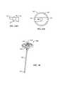
- FIG. 1illustrates a perspective view of a spinal fixation device in accordance with one embodiment of the invention.
- FIG. 2illustrates a perspective view of spinal fixation device in accordance with another embodiment of the invention.
- FIG. 3illustrates an exploded view of the coupling assembly 14 of the pedicle screw 2 of FIGS. 1 and 2 , in accordance with one embodiment of the invention.
- FIG. 4illustrates a perspective view of a flexible rod connection unit in accordance with one embodiment of the invention.
- FIG. 5illustrates a perspective view of a flexible rod connection unit in accordance with another embodiment of the invention.
- FIG. 6illustrates a perspective view of a flexible rod connection unit in accordance with a further embodiment of the invention.
- FIG. 7illustrates a perspective view of a pre-bent flexible rod connection unit in accordance with one embodiment of the invention.
- FIG. 8illustrates a perspective, cross-sectional view of a flexible portion of connection unit in accordance with one embodiment of the invention.
- FIG. 9illustrates a perspective, cross-sectional view of a flexible portion of connection unit in accordance with another embodiment of the invention.
- FIG. 10illustrates a perspective, cross-sectional view of a flexible portion of connection unit in accordance with a further embodiment of the invention.
- FIG. 11illustrates a perspective view of a flexible rod connection unit in accordance with one embodiment of the invention.
- FIG. 12Aillustrates a perspective view of a flexible connection unit having one or more spacers in between two end portions, in accordance with one embodiment of the invention.
- FIG. 12Billustrates an exploded view of the flexible connection unit of FIG. 12A .
- FIG. 12Cprovides a view of the male and female interlocking elements of the flexible connection unit of FIGS. 12A and 12B , in accordance with one embodiment of the invention.
- FIG. 13shows a perspective view of a flexible connection unit, in accordance with a further embodiment of the invention.
- FIG. 14illustrates a perspective view of a spinal fixation device in accordance with another embodiment of the invention.
- FIG. 15illustrates an exploded view of the spinal fixation device of FIG. 14 .
- FIG. 16Ashows a perspective view of a flexible plate connection unit in accordance with one embodiment of the invention.
- FIG. 16Billustrates a perspective view of a flexible plate connection unit in accordance with a further embodiment of the invention.
- FIG. 16Cshows a side view of the flexible plate connection unit of FIG. 16A .
- FIG. 16Dshows a top view of the flexible plate connection unit of FIG. 16A .
- FIG. 16Eillustrates a side view of the flexible plate connection unit of FIG. 16A having a pre-bent configuration in accordance with a further embodiment of the invention.
- FIG. 17is a perspective view of a flexible plate connection unit in accordance with another embodiment of the invention.
- FIG. 18illustrates a perspective view of a flexible plate connection unit in accordance with another embodiment of the invention.
- FIG. 19illustrates a perspective view of a hybrid rod-plate connection unit having a flexible middle portion according to a further embodiment of the present invention.
- FIG. 20is a perspective view of a spinal fixation device that utilizes the hybrid rod-plate connection unit of FIG. 19 .
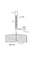
- FIG. 21illustrates a perspective view of the spinal fixation device of FIG. 1 after it has been implanted into a patient's spinal column.
- FIGS. 22A and 22Bprovide perspective views of spinal fixation devices utilizing the plate connection units of FIGS. 16A and 16B , respectively.
- FIG. 23Aillustrates a perspective view of two pedicle screws inserted into the pedicles of two adjacent vertebrae at a skewed angle, in accordance with one embodiment of the invention.
- FIG. 23Billustrates a structural view of a coupling assembly of a pedicle screw in accordance with one embodiment of the invention.
- FIG. 23Cprovides a perspective view of a slanted stabilizing spacer in accordance with one embodiment of the invention.
- FIG. 23Dillustrates a side view of the slanted stabilizing spacer of FIG. 23C .
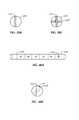
- FIG. 23Eis a top view of the cylindrical head of the pedicle screw of FIG. 23 .
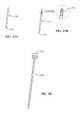
- FIG. 24illustrates a perspective view of a marking and guiding device in accordance with one embodiment of the invention.
- FIG. 25is an exploded view of the marking and guidance device of FIG. 24 .
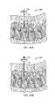
- FIG. 26Aprovides a perspective, cross-section view of a patient's spine after the marking and guiding device of FIG. 24 has been inserted during surgery.
- FIG. 26Bprovides a perspective, cross-section view of a patient's spine as an inner trocar of the marking and guiding device of FIG. 24 is being removed.
- FIGS. 27A and 27Billustrate perspective views of two embodiments of a fiducial pin, respectively.
- FIG. 28is a perspective view of a pushing trocar in accordance with a further embodiment of the invention.
- FIG. 29Aillustrates a perspective, cross-sectional view of a patient's spine as the pushing trocar of FIG. 28 is used to drive a fiducial pin into a designate location of a spinal pedicle, in accordance with one embodiment of the invention.
- FIG. 29Billustrates a perspective, cross-sectional view of a patient's spine after two fiducial pins have been implanted into two adjacent spinal pedicles, in accordance with one embodiment of the invention.
- FIG. 30is a perspective view of a cannulated awl in accordance with one embodiment of the invention.
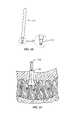
- FIG. 31is a perspective, cross-sectional view of a patient's spine as the cannulated awl of FIG. 30 is being used to enlarge an entry hole for a pedicle screw, in accordance with one embodiment of the invention.
- FIG. 32provides a perspective view of fiducial pin retrieving device, in accordance with one embodiment of the invention.
- FIG. 33is a perspective view of a pedicle screw having an axial cylindrical cavity for receiving at least a portion of a fiducial pin therein, in accordance with a further embodiment of the invention.
- FIG. 34is a perspective, cross-sectional view of a patient's spine after one pedicle screw has been implanted into a designated location of a spinal pedicle, in accordance with one embodiment of the invention.
- FIG. 35is a perspective, cross-sectional view of a patient's spine after two pedicle screws have been implanted into designated locations of two adjacent spinal pedicles, in accordance with one embodiment of the invention.
- FIG. 36Ais perspective view of a flexible rod for spinal fixation having a spiral groove cut therein, in accordance with one embodiment of the present invention.
- FIG. 36Bprovides a cross-sectional view of the flexible rod of FIG. 36A , taken along lines B-B of FIG. 36A .
- FIG. 37Aillustrates a perspective view of a flexible rod for spinal fixation having transverse tunnels within the body of the rod, in accordance with one embodiment of the invention.
- FIG. 37Bis a cross-sectional view of the flexible rod of FIG. 37A , taken along lines B-B of FIG. 37A .
- FIG. 38Ais a perspective view of a flexible rod for spinal fixation having a spiral groove cut therein and transverse tunnels in the body of the rod, in accordance with a further embodiment of the invention.
- FIG. 38Bis a top view of the flexible rod of FIG. 38A , from the perspective of lines B-B of FIG. 38A .
- FIG. 39Ais a perspective view of a flexible rod for spinal fixation having transverse tunnels within the body of the rod, in accordance with another embodiment of the invention.
- FIG. 39Bis a cross-sectional view of the flexible rod of FIG. 39A , taken along lines B-B of that figure.
- FIG. 39Cis an alternative cross-sectional view of the flexible rod of FIG. 39A , taken along lines B-B of that figure, having substantially orthogonal transverse tunnels in the body of the rod, in accordance with a further embodiment of the invention.
- FIG. 40Aillustrates a perspective view of a flexible rod for spinal fixation, in accordance with a further embodiment of the invention.
- FIG. 40Billustrates a cross-sectional view of a flexible rod for spinal fixation in accordance with a further embodiment of the invention.
- FIG. 41Aillustrates a perspective view of a flexible longitudinal member connection unit in accordance with one embodiment of the invention.
- FIG. 41Billustrates a perspective view of the connection unit of FIG. 41A assembled with securing members.
- FIG. 41Cillustrates a perspective view of a flexible longitudinal member trimmed to length and assembled with securing members.
- FIG. 42Aillustrates a side view of a flexible longitudinal member connection unit in accordance with a further embodiment of the invention.
- FIG. 42Billustrates a side view of a flexible longitudinal member connection unit in accordance with another embodiment of the invention.
- FIG. 43Aillustrates a side view of a flexible longitudinal member connection unit in accordance with another embodiment of the invention.
- FIG. 43Billustrates a perspective view of a flexible longitudinal member connection unit in accordance with another embodiment of the invention.
- FIG. 43Cillustrates a side view of a flexible longitudinal member connection unit in accordance with another embodiment of the invention.
- FIG. 43Dillustrates a side view of a flexible longitudinal member connection unit in accordance with another embodiment of the invention.
- FIG. 44illustrates a perspective view of a flexible longitudinal member connection unit in accordance with a further embodiment of the invention.
- FIG. 45Aillustrates a cross-section view of a flexible longitudinal member connection unit in accordance with an embodiment of the invention.
- FIG. 45Billustrates a cross-section view of a flexible longitudinal member made of two types of material in accordance with another embodiment of the invention.
- FIGS. 46A-Cillustrate perspective views of a metal-hybrid longitudinal member with an elastomer cladding, in accordance with various embodiments of the invention.
- FIGS. 47A-Billustrate perspective views of a longitudinal member having at least one spacer and an elastomer, in accordance with various embodiments of the invention.
- FIG. 48illustrates a flexible connection unit having a spacer and an elastomer cladding, in accordance with another embodiment of the invention.
- FIG. 49illustrates a flexible connection unit having a spacer and an elastomer cladding, in accordance with another embodiment of the invention.
- FIGS. 50A-Dillustrate a variety of features for improved fixation of the elastomer cladding to a rigid surface, in accordance with various embodiments of the invention.
- FIGS. 51-52illustrates two respective embodiments of a flexible connection unit having at least one spacer and an elastomer cladding, in accordance with the invention.
- FIG. 52Aillustrates a cross sectional diagram of a metal-hybrid spacer as shown in FIG. 52 , in accordance with one embodiment of the present invention.
- FIG. 53illustrates two flexible connection units as shown in FIG. 52 attached to a patient's spine, in accordance with one embodiment of the present invention.
- FIGS. 54-55illustrates additional embodiments of a flexible connection unit having at least one spacer and an elastomer cladding, in accordance with the invention.
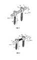
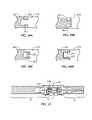
- FIG. 1depicts a spinal fixation device in accordance with one embodiment of the present invention.
- the spinal fixation deviceincludes two securing members 2 (designated as 2 ′ and 2 ′′), and a flexible fixation rod 4 configured to be received and secured within a coupling assembly 14 , as described in further detail below with respect to FIG. 3 .
- Each securing member 2includes a threaded screw-type shaft 10 configured to be inserted and screwed into a patient's spinal pedicle.
- the screw-type shaft 10includes an external spiral screw thread 12 formed over the length of the shaft 10 and a conical tip at the end of the shaft 10 configured to be inserted into the patient's spinal column at a designated location.
- Other known forms of the securing member 2may be used in connection with the present invention provided the securing member 2 can be inserted and fixed into the spinal column and securely coupled to the rod 4 .
- the spinal fixation deviceis used for surgical treatment of spinal diseases by mounting securing members 2 at desired positions in the spinal column.
- the rod 4extends across two or more vertebrae of the spinal column and is secured by the securing members 2 so as to stabilize movement of the two or more vertebrae.
- FIG. 2illustrates a perspective view of a spinal fixation device in accordance with a further embodiment of the present invention.
- the spinal fixation device of FIG. 2is similar to the spinal fixation device of FIG. 1 except that the rod 4 comprises a flexible middle portion 8 juxtaposed between two rigid end portions 9 of the rod 4 .
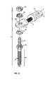
- FIG. 3provides an exploded view of the securing member 2 of FIGS. 1 and 2 illustrating various components of the coupling assembly 14 , in accordance with one embodiment of the invention.
- the coupling assembly 14includes: a cylindrical head 16 located at a top end of the screw-type shaft 10 , a spiral thread or groove 18 formed along portions of the inner wall surface of the cylindrical head 16 , and a U-shaped seating groove 20 configured to receive the rod 4 therein.
- the coupling assembly 14further comprises an outside-threaded nut 22 having a spiral thread 24 formed on the outside lateral surface of the nut 22 , wherein the spiral thread 24 is configured to mate with the internal spiral thread 18 of the cylindrical head 16 .
- the coupling assembly 14includes a fixing cap 26 configured to be mounted over a portion of the cylindrical head 16 to cover and protect the outside-threaded nut 22 and more securely hold rod 4 within seating groove 20 .
- an inner diameter of the fixing gap 26is configured to securely mate with the outer diameter of the cylindrical head 16 .
- Other methods of securing the fixing cap 26 to the cylindrical head, such as correspondingly located notches and groove (not shown),would be readily apparent to those of skill in the art.
- the components and parts of the securing member 2may be made of highly rigid and durable bio-compatible materials such as stainless steel, iron steel, titanium or titanium alloy.
- non-metal biocompatible materialsmay also be utilized such as polymers, elastomers, resins, ceramics, and composites thereof. Such materials are known in the art.
- bio-compatible materialsrefers to those materials that will not cause any adverse chemical or immunological reactions after being implanted into a patient's body.
- the rod 4is coupled to the securing means 2 by seating the rod 4 horizontally into the seating groove 20 of the coupling means 14 perpendicularly to the direction of the length of the threaded shaft 10 of securing member 2 .
- the outside threaded nut 22is then received and screwed into the cylindrical head 16 above the rod 4 so as to secure the rod 4 in the seating groove 20 .
- the fixing cap 26is then placed over the cylindrical head 16 to cover, protect and more firmly secure the components in the internal cavity of the cylindrical head 16 .
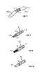
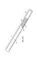
- FIGS. 4-7illustrate perspective views of various embodiments of a rod 4 that may be used in a fixation device, in accordance with the present invention.
- FIG. 4illustrates the rod 4 of FIG.
- rod 4comprises a metal tube or pipe having a cylindrical wall 5 of a predefined thickness.
- the rod 4may comprise a tube made from a biocompatible metal-synthetic hybrid material or entirely from a biocompatible synthetic material.
- biocompatible metalsare: titanium, stainless steel, zirconium, tantalum, cobalt, chromium, nickel and alloys thereof.
- biocompatible synthetic materialsare: polymers, elastomers, resins, plastics, carbon graphite and composites thereof. Such materials are well known in the art.
- the cylindrical wall 5is cut in a spiral fashion along the length of the rod 4 to form spiral cuts or grooves 6 .
- the width and density of the spiral grooves 6may be adjusted to provide a desired level of flexibility.
- the grooves 6are formed from very thin spiral cuts or incisions that penetrate through the entire thickness of the cylindrical wall of the rod 4 .
- the thickness and material of the tubular walls 5also affect the level of flexibility.
- the rod 4is designed to have a flexibility that substantially equals that of a normal back. Flexibility ranges for a normal back are known by those skilled in the art, and one of ordinary skill can easily determine a thickness and material of the tubular walls 5 and a width and density of the grooves 6 to achieve a desired flexibility or flexibility range within the range for a normal back.
- the term “density”refers to tightness of the spiral grooves 6 or, in other words, the distance between adjacent groove lines 6 as shown in FIG. 4 , for example.
- the present inventionis not limited to a particular, predefined flexibility range.
- the rigidity of the rod 4should be able to endure a vertical axial load applied to the patient's spinal column along a vertical axis of the spine in a uniform manner with respect to the rest of the patient's natural spine.
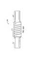
- FIG. 5illustrates the rod 4 of FIG. 2 wherein only a middle portion 8 is made and designed to be flexible and two end portions 9 are made to be rigid.
- metal end rings or caps 9 ′having no grooves therein, may be placed over respective ends of the rod 4 of FIG. 4 so as make the end portions 9 rigid.
- the rings or caps 9 ′may be permanently affixed to the ends of the rod 4 using known methods such as pressing and/or welding the metals together.
- the spiral groove 6is only cut along the length of the middle portion 8 and the end portions 9 comprise the tubular wall 5 without grooves 6 . Without the grooves 6 , the tubular wall 5 , which is made of a rigid metal or metal hybrid material, exhibits high rigidity.
- FIG. 6illustrates a further embodiment of the rod 4 having multiple sections, two flexible sections 8 interleaved between three rigid sections 9 .
- This embodimentmay be used, for example, to stabilize three adjacent vertebrae with respect to each other, wherein three pedicle screws are fixed to a respective one of the vertebrae and the three rigid sections 9 are connected to a coupling assembly 14 of a respective pedicle screw 2 , as described above with respect to FIG. 3 .
- Each of the flexible sections 8 and rigid sections 9may be made as described above with respect to FIG. 5 .
- FIG. 7illustrates another embodiment of the rod 4 having a pre-bent structure and configuration to conform to and maintain a patient's curvature of the spine, known as “lordosis,” while stabilizing the spinal column.
- a patient's lumbaris in the shape of a ‘C’ form, and the structure of the rod 4 is formed to coincide to the normal lumbar shape when utilized in the spinal fixation device of FIG. 2 , in accordance with one embodiment of the invention.
- the pre-bent rod 4includes a middle portion 8 that is made and designed to be flexible interposed between two rigid end portions 9 .
- the middle portion 8 and end portions 9may be made as described above with respect to FIG. 5 .
- the pre-bent structure and design of the rod 4may offset a skew angle when two adjacent pedicle screws are not inserted parallel to one another, as described in further detail below with respect to FIG. 23A .
- FIG. 8illustrates a perspective, cross-sectional view of a flexible tubular rod 4 , or rod portion 8 in accordance with one embodiment of the invention.
- the flexible rod 4 , 8is made from a first metal tube 5 having a spiral groove 6 cut therein as described above with respect to FIGS. 4-7 .
- a second tube 30 having spiral grooves 31 cut therein and having a smaller diameter than the first tube 5is inserted into the cylindrical cavity of the first tube 5 .
- the second tube 30has spiral grooves 31 which are cut in an opposite spiral direction with respect to the spiral grooves 6 cut in the first tube 5 , such that the rotational torsion characteristics of the second tube 30 offset at least some of the rotational torsion characteristics of the first tube 5 .
- the second flexible tube 30is inserted into the core of the first tube to provide further durability and strength to the flexible rod 4 , 8 .
- the second tube 30may be made of the same or different material than the first tube 5 .
- the material used to manufacture the first and second tubes 5 and 30may be any one or combination of the following exemplary biocompatible metals: titanium, stainless steel, zirconium, tantalum, cobalt, chromium, nickel, aluminum, vanadium, and alloys thereof.
- the tubes 5 and 30may be made from a biocompatible metal-synthetic hybrid material or entirely from a biocompatible synthetic material. Examples of biocompatible synthetic materials are: polymers, elastomers, resins, plastics, carbon graphite and composites thereof. Such materials are well known in the art.
- FIG. 9illustrates a perspective, cross-sectional view of a flexible rod 4 , 8 in accordance with a further embodiment of the invention.
- the flexible rod 4 , 8includes an inner core made of a biocompatible metallic wire 32 comprising a plurality of overlapping thin metallic yarns, such as steel yarns, titanium yarns, or titanium-alloy yarns.
- the wire 32is encased by a metal, or metal hybrid, flexible tube 5 having spiral grooves 6 cut therein, as discussed above.
- the number and thickness of the metallic yarns in the wire 32also affects the rigidity and flexibility of the rod 4 , 8 . By changing the number, thickness or material of the yarns flexibility can be increased or decreased.
- the number, thickness and/or material of the metallic yarns in the wire 32can be adjusted to provide a desired rigidity and flexibility in accordance with a patient's particular needs.
- Those of ordinary skill in the artcan easily determine the number, thickness and material of the yarns, in conjunction with a given flexibility of the tube 5 in order to achieve a desired rigidity v. flexibility profile for the rod 4 , 8 .
- the wire 32 and plurality of yarnsmay be made from a biocompatible metal-synthetic hybrid material or entirely from biocompatible synthetic materials, as discussed above.
- FIG. 10shows yet another embodiment of a flexible rod 4 wherein the flexible tube 5 encases a non-metallic, flexible core 34 .
- the core 34may be made from, for example, known biocompatible metals, biocompatible shape memory alloys (e.g., NITINOL), or biocompatible synthetic materials such as carbon fiber, Poly Ether Ether Ketone (PEEK), Poly Ether Ketone Ketone Ether Ketone (PEKKEK), or Ultra High Molecular Weight Poly Ethylene (UHMWPE).
- PEEKPoly Ether Ether Ketone
- PEKKEKPoly Ether Ketone Ketone Ether Ketone
- UHMWPEUltra High Molecular Weight Poly Ethylene
- FIG. 11illustrates a perspective view of another embodiment of the flexible rod 35 in which a plurality of wires 32 , as described above with respect to FIG. 9 , are interweaved or braided together to form a braided wire rod 35 .
- the braided wire rod 35can be made from the same materials as the wire 32 discussed above.
- the rigidity and flexibility of the braided rod 35can be further modified to achieve desired characteristics by varying the number and thickness of the wires 32 used in the braided structure 35 .
- each end of the braided wire rod 35is encased by a rigid cap or ring 9 ′ as described above with respect to FIGS. 5-7 , to provide a rod 4 having a flexible middle portion 8 and rigid end portions 9 .
- the braided wire rod 35may be utilized as a flexible inner core encased by a tube 5 having spiral grooves 6 cut therein to create a flexible rod 4 or rod portion 8 , in a similar fashion to the embodiments shown in FIGS. 8-10 .
- the term “braid” or “braided structure”encompasses two or more wires, strips, strands, ribbons and/or other shapes of material interwoven in an overlapping fashion. Various methods of interweaving wires, strips, strands, ribbons and/or other shapes of material are known in the art. Such interweaving techniques are encompassed by the present invention.
- the flexible rod 35includes a braided structure having two or more strips, strands or ribbons interweaved in a diagonally overlapping pattern.
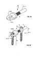
- FIG. 12Aillustrates a further embodiment of a flexible connection unit 36 having two rigid end portions 9 ′ and an exemplary number of spacers 37 interposed between the end portions.
- the rigid end portions 9 ′ and spacerscan be made of bio-compatible metal, metal-hybrid, and/or synthetic materials as discussed above.
- the connection unit 36further includes a flexible member or wire 32 , as discussed above with respect to FIG. 9 , which traverses an axial cavity or hole (not shown) in each of the rigid end portions 9 ′ and spacers 37 .
- FIG. 12Billustrates an exploded view of the connection unit 36 that further shows how the wire 32 is inserted through longitudinal axis holes of the rigid end portions 9 ′ and spacers 37 . As further shown in FIG.
- each of the end portions 9 ′ and spacers 37include a male interlocking member 38 which is configured to mate with a female interlocking cavity (not shown) in the immediately adjacent end portion 9 ′ or spacer 37 .
- FIG. 12Cillustrates an exploded side view and indicates with dashed lines the location and configuration of the female interlocking cavity 39 for receiving corresponding male interlocking members 38 .
- FIG. 13shows a perspective view of a flexible connection unit 40 in accordance with another embodiment of the invention.
- the connection unit 40is similar to the connection unit 36 described above, however, the spacers 42 are configured to have the same shape and design as the rigid end portions 9 ′. Additionally, the end portions 9 ′ have an exit hole or groove 44 located on a lateral side surface through which the wire 32 may exit, be pulled taut, and clamped or secured using a metal clip (not shown) or other known techniques. In this way, the length of the flexible connection unit 36 or 40 may be varied at the time of surgery to fit each patient's unique anatomical characteristics.
- the wire 32may be secured using a metallic clip or stopper (not shown).
- a clip or stoppermay include a small tubular cylinder having an inner diameter that is slightly larger than the diameter of the wire 32 to allow the wire 32 to pass therethrough. After the wire 32 is pulled to a desired tension through the tubular stopper, the stopper is compressed so as to pinch the wire 32 contained therein.
- the wire 32may be pre-secured using known techniques during the manufacture of the connection units 36 , 40 having a predetermined number of spacers 37 , 42 therein.
- FIG. 14depicts a spinal fixation device according to another embodiment of the present invention.
- the spinal fixation deviceincludes: at least two securing members 2 containing an elongate screw type shaft 10 having an external spiral thread 12 , and a coupling assembly 14 .
- the devicefurther includes a plate connection unit 50 , or simply “plate 50 ,” configured to be securely connected to the coupling parts 14 of the two securing members 2 .
- the plate 50comprises two rigid connection members 51 each having a planar surface and joined to each other by a flexible middle portion 8 .
- the flexible middle portion 8may be made in accordance with any of the embodiments described above with respect to FIGS. 4-11 .
- Each connection member 51contains a coupling hole 52 configured to receive therethrough a second threaded shaft 54 ( FIG. 15 ) of the coupling assembly 14 .
- the coupling assembly 14 of the securing member 2includes a bolt head 56 adjoining the top of the first threaded shaft 10 and having a circumference or diameter greater than the circumference of the first threaded shaft 10 .
- the second threaded shaft 54extends upwardly from the bolt head 56 .
- the coupling assembly 14further includes a nut 58 having an internal screw thread configured to mate with the second threaded shaft 54 , and one or more washers 60 , for clamping the connection member 51 against the top surface of the bolt head 56 , thereby securely attaching the plate 50 to the pedicle screw 2 .
- FIGS. 16A and 16Billustrate two embodiments of a plate connection unit 40 having at least two coupling members 51 and at least one flexible portion 8 interposed between and attached to two adjacent connection members 51 .
- the flexible middle portion 8comprises a flexible braided wire structure 36 as described above with respect to FIG. 11 .
- the flexible portion 8can be designed and manufactured in accordance with any of the embodiments described above with respect to FIGS. 4-11 , or combinations thereof.
- FIGS. 16C and 16Dillustrate a side view and top view, respectively, of the plate 50 of FIG. 16A .
- the manufacture of different embodiments of the flexible connection units 50 and 58 having different types of flexible middle portions 8is easily accomplished using known metallurgical, organic polymer, natural resin, or composite materials, and compatible manufacturing and machining processes.
- FIG. 16Eillustrate a side view of a pre-bent plate connection unit 50 ′, in accordance with a further embodiment of the invention.
- This plate connection unit 50 ′is similar to the plate 50 except that connection members 51 ′ are formed or bent at an angle ⁇ from a parallel plane 53 during manufacture of the plate connection unit 50 ′.
- this pre-bent configurationis designed to emulate and support a natural curvature of the spine (e.g., lordosis). Additionally, or alternatively, this pre-bent structure may offset a skew angle when two adjacent pedicle screws are not inserted parallel to one another, as described in further detail below with respect to FIG. 23A .
- FIG. 17illustrates a perspective view of a plate connection unit 60 having two planar connection members 62 each having a coupling hole 64 therein for receiving the second threaded shaft 44 of the pedicle screw 2 .
- a flexible middle portion 8is interposed between the two connection members 62 and attached thereto.
- the flexible middle portion 8is made in a similar fashion to wire 32 described above with respect to FIG. 9 , except it has a rectangular configuration instead of a cylindrical or circular configuration as shown in FIG. 9 . It is understood, however, that the flexible middle portion 8 may be made in accordance with the design and materials of any of the embodiments previously discussed.
- FIG. 18illustrates a perspective view of a further embodiment of the plate 60 of FIG. 17 wherein the coupling hole 64 includes one or more nut guide grooves 66 cut into the top portion of the connection member 62 to seat and fix the nut 58 ( FIG. 15 ) into the coupling hole 64 .
- the nut guide groove 66is configured to receive and hold at least a portion of the nut 58 therein and prevent lateral sliding of the nut 58 within the coupling hole 64 after the connection member 62 has been clamped to the bolt head 56 of the pedicle screw 2 .
- FIG. 19illustrates a perspective view of a hybrid plate and rod connection unit 70 having a rigid rod-like connection member 4 , 9 or 9 ′, as described above with respect to FIGS. 4-7 , at one end of the connection unit 70 and a plate-like connection member 51 or 62 , as described above with respect to FIGS. 14-18 , at the other end of the connection unit 70 .
- a flexible member 8interposed between rod-like connection member 9 ( 9 ′) and the plate-like connection member 52 ( 64 ) is a flexible member 8 .
- the flexible member 8may be designed and manufactured in accordance with any of the embodiments discussed above with reference to FIGS. 8-13 .
- FIG. 20illustrates a perspective view of a spinal fixation device that utilizes the hybrid plate and rod connection unit 70 of FIG. 19 .
- this fixation deviceutilizes two types of securing members 2 (e.g., pedicle screws), the first securing member 2 ′ being configured to securely hold the plate connection member 42 ( 64 ) as described above with respect to FIG. 15 , and the second securing member 2 ′′ being configured to securely hold the rod connection member 4 , 9 or 9 ′, as described above with respect to FIG. 3 .
- securing members 2e.g., pedicle screws
- FIG. 21illustrates a perspective top view of two spinal fixation devices, in accordance with the embodiment illustrated in FIG. 1 , after they are attached to two adjacent vertebrae 80 and 82 to flexibly stabilize the vertebrae.
- FIGS. 22A and 22Billustrate perspective top views of spinal fixation devices using the flexible stabilizing members 50 and 58 of FIGS. 16A and 16B , respectively, after they are attached to two or more adjacent vertebrae of the spine.
- FIG. 23Aillustrates a side view of a spinal fixation device after it has been implanted into the pedicles of two adjacent vertebrae.
- the pedicle screws 2are mounted into the pedicle bone such that a center axis 80 of the screws 2 are offset by an angle ⁇ from a parallel plane 82 and the center axes 80 of the two screws 2 are offset by an angle of approximately 20 from each other.
- This type of non-parallel insertion of the pedicle screws 2often results due to the limited amount of space that is available when performing minimally invasive surgery.
- the pedicle screws 2may have a tendency to be skewed from parallel due to a patient's natural curvature of the spine (e.g., lordosis).
- lordosise.g., lordosis
- FIG. 23Billustrates a side view of the head of the pedicle screw in accordance with one embodiment of the invention.
- the screw 2includes a cylindrical head 84 which is similar to the cylindrical head 16 described above with respect to FIG. 3 except that the cylindrical head 84 includes a slanted seat 86 configured to receive and hold a flexible rod 4 in a slanted orientation that offsets the slant or skew ⁇ of the pedicle screw 2 as described above.
- the improved pedicle screw 2further includes a slanted stabilizing spacer 88 which is configured to securely fit inside the cavity of the cylindrical head 84 and hold down the rod 4 at the same slant as the slanted seat 86 .
- the pedicle screw 2further includes an outside threaded nut 22 configured to mate with spiral threads along the interior surface (not shown) of the cylindrical head 84 for clamping down and securing the slanted spacer 88 and the rod 4 to the slanted seat 86 and, hence, to the cylindrical head 84 of the pedicle screw 2 .
- FIG. 23Cshows a perspective view of the slanted spacer 88 , in accordance with one embodiment of the invention.
- the spacer 88includes a circular middle portion 90 and two rectangular-shaped end portions 92 extending outwardly from opposite sides of the circular middle portion 90 .
- FIG. 23Dshows a side view of the spacer 88 that further illustrates the slant from one end to another to compensate or offset the skew angle ⁇ of the pedicle screw 2 .
- FIG. 23Eillustrates a top view of the cylindrical head 84 configured to receive a rod 4 and slanted spacer 88 therein.
- the rod 4is received through two openings or slots 94 in the cylindrical walls of the cylindrical head 84 , which allow the rod 4 to enter the circular or cylindrical cavity 96 of the cylindrical head 84 and rest on top of the slanted seat 86 formed within the circular or cylindrical cavity 94 .
- the slanted stabilizing spacer 88is received in the cavity 96 such that the two rectangular-shaped end portions 92 are received within the two slots 94 , thereby preventing lateral rotation of the spacer 88 within the cylindrical cavity 96 .
- the outside threaded nut 22 and fixing cap 26are inserted on top of the slanted spacer 88 to securely hold the spacer 88 and rod 4 within the cylindrical head 84 .
- FIG. 24illustrates a perspective view of a marking and guidance device 100 for marking a desired location on the spinal pedicle where a pedicle screw 2 will be inserted and guiding the pedicle screw 2 to the marked location using a minimally invasive surgical technique.
- the marking device 100includes a tubular hollow guider 52 which receives within its hollow an inner trocar 104 having a sharp tip 105 at one end that penetrates a patient's muscle and tissue to reach the spinal pedicle.
- the inner trocar 104further includes a trocar grip 106 at the other end for easy insertion and removal of the trocar 104 .
- the marking and guidance device 100includes a guider handle 108 to allow for easier handling of the device 100 .
- the trocar 104is in the form of a long tube or cylinder having a diameter smaller than the inner diameter of the hollow of the guider 102 so as to be inserted into the hollow of the tubular guider 102 .
- the trocar 104further includes a sharp or pointed tip 105 for penetrating the vertebral body through the pedicle.
- the trocar 104further includes a trocar grip 106 having a diameter larger than the diameter of the hollow of the guider tube 102 in order to stop the trocar 104 from sliding completely through the hollow.
- the trocar grip 106also allows for easier handling of the trocar 104 .
- FIGS. 26A and 26Bprovide perspective views of the marking and guidance device 100 after it has been inserted into a patient's back and pushed through the muscle and soft tissue to reach a desired location on the spinal pedicle.
- the desired locationis determined using known techniques such as x-ray or radiographic imaging for a relatively short duration of time.
- prolonged exposure of the patient to x-ray radiationis unnecessary.
- the inner trocar 104is removed to allow fiducial pins (not shown) to be inserted into the hollow of the guidance tube 102 and thereafter be fixed into the pedicle.
- FIGS. 27A and 27Billustrate perspective views of two embodiments of the fiducial pins 110 and 112 , respectively.
- the fiducial pins 110 and 112according to the present invention are inserted and fixed into the spinal pedicle after passing through the hollow guider 102 .
- the pins 110 and 112have a cylindrical shape with a diameter smaller than the inner diameter of the hollow of the guider tube 102 in order to pass through the hollow of the guider 102 .
- An end of each fiducial pinis a sharp point 111 configured to be easily inserted and fixed into the spinal pedicle of the spinal column. In one embodiment, as shown in FIG.
- the other end of the fiducial pinincorporates a threaded shaft 114 which is configured to mate with an internally threaded tube of a retriever (not shown) for extraction of the pin 112 .
- This retrieveris described in further detail below with respect to FIG. 32 .
- the fiducial pins 110 , 112are preferably made of a durable and rigid biocompatible metal (e.g., stainless steel, iron steel, titanium, titanium alloy) for easy insertion into the pedicle bone.
- a durable and rigid biocompatible metale.g., stainless steel, iron steel, titanium, titanium alloy
- the fiducial pins 110 , 112are easily driven into the spinal pedicle without risk of bending or structural failure.
- the process of driving in prior art guidance wireswas often very difficult and time-consuming.
- the insertion of the fiducial pins 110 , 112 into the entry point on the spinal pedicleis much easier and convenient for the surgeon and, furthermore, does not hinder subsequent procedures due to a guide wire protruding out of the patient's back.
- FIG. 28shows a cylindrical pushing trocar 116 having a cylindrical head 118 of larger diameter than the body of the pushing trocar 116 .
- the pushing trocar 116is inserted into the hollow of the guider 102 after the fiducial pin 110 or 112 has been inserted into the hollow of the guider 102 to drive and fix the fiducial pin 110 or 112 into the spinal pedicle.
- a doctorstrikes the trocar head 118 with a chisel or a hammer to drive the fiducial pin 110 and 112 into the spinal pedicle.
- the pushing trocar 116is in the form of a cylindrical tube, which has a diameter smaller than the inner diameter of the hollow of the guider tube 112 .
- the pushing trocar 116also includes a cylindrical head 118 having a diameter larger than the diameter of the pushing trocar 116 to allow the doctor to strike it with a chisel or hammer with greater ease.
- a hammer or chiselis not necessarily required.
- a surgeonmay choose to push or tap the head 118 of the pushing trocar 116 with the palm of his or her hand or other object.
- FIG. 29Aillustrates how a hammer or mallet 120 and the pushing trocar 116 may be used to drive the pin 110 , 112 through the hollow of the guider tube 102 and into the designated location of the spinal pedicle.
- FIG. 29Billustrates a perspective cross-sectional view of the spinal column after two fiducial pins 110 , 112 have been driven and fixed into two adjacent vertebrae.
- a larger hole or area centered around each pin 110 , 112is created to allow easer insertion and mounting of a pedicle screw 2 into the pedicle bone.
- the larger holeis created using a cannulated awl 122 as shown in FIG. 30 .
- the cannulated awl 122is inserted over the fiducial pin 110 , 112 fixed at the desired position of the spinal pedicle.
- the awl 122is in the form of a cylindrical hollow tube wherein an internal diameter of the hollow is larger than the outer diameter of the fiducial pins 110 and 112 so that the pins 110 , 112 may be inserted into the hollow of the awl 122 .
- the awl 122further includes one or more sharp teeth 124 at a first end for cutting and grinding tissue and bone so as to create the larger entry point centered around the fiducial pin 110 , 112 so that the pedicle screw 2 may be more easily implanted into the spinal pedicle.
- FIG. 31illustrates a perspective cross-sectional view of a patient's spinal column when the cannulated awl 122 is inserted into a minimally invasive incision in the patient's back, over a fiducial pin 110 , 112 to create a larger insertion hole for a pedicle screw 2 (not shown).
- a retractor 130has been inserted into the minimally invasive incision over the surgical area and a lower tubular body of the retractor 130 is expanded to outwardly push surrounding tissue away from the surgical area and provide more space and a visual field for the surgeon to operate.
- the minimally invasive incisionis made in the patient's back between and connecting the two entry points of the guide tube 102 used to insert the two fiducial pins 110 , 112 .
- prior expansion of the minimally invasive incisionis typically required using a series of step dilators (not shown), each subsequent dilator having a larger diameter than the previous dilator.
- the retractor 130is inserted with its lower tubular body in a retracted, non-expanded state. After the retractor 130 is pushed toward the spinal pedicle to a desired depth, the lower tubular portion is then expanded as shown in FIG. 31 .
- step dilators and retractorsare well known in the art.
- the fiducial pin 110 , 112is removed.
- a retrieving device 140may be used to remove the fiducial pin 112 before implantation of a pedicle screw 2 .
- the retriever 140comprises a long tubular or cylindrical portion having an internally threaded end 142 configured to mate with the externally threaded top portion 114 of the fiducial pin 112 .
- a doctormy pull the fiducial pin 112 out of the spinal pedicle.
- appropriate toolse.g., specially designed needle nose pliers
- the fiducial pins 110 , 112are not extracted from the spinal pedicle. Instead, a specially designed pedicle screw 144 may be inserted into the spinal pedicle over the pin 110 , 112 without prior removal of the pin 110 , 112 .
- the specially designed pedicle screw 144includes an externally threaded shaft 10 and a coupling assembly 14 ( FIG. 3 ) that includes a cylindrical head 16 ( FIG. 3 ) for receiving a flexible rod-shaped connection unit 4 ( FIGS. 4-13 ).
- the coupling assembly 14may be configured to receive a plate-like connection unit as shown in FIGS. 14-20 .
- the pedicle screw 144further includes a longitudinal axial channel (not shown) inside the threaded shaft 10 having an opening 146 at the tip of the shaft 10 and configured to receive the fiducial pin 110 , 112 therein.
- FIG. 34illustrates a perspective cross-sectional view of the patient's spinal column after a pedicle screw 2 has been inserted into a first pedicle of the spine using an insertion device 150 .
- Various types of insertion devices 150 known in the artmay be used to insert the pedicle screw 2 .
- the retractor 130is adjusted and moved slightly to provide space and a visual field for insertion of a second pedicle screw at the location of the second fiducial pin 110 , 112 .
- FIG. 35provides a perspective, cross sectional view of the patient's spinal column after two pedicle screws 2 have been implanted in two respective adjacent pedicles of the spine, in accordance with the present invention.
- a flexible rod, plate or hybrid connection unitas described above with respect to FIGS. 4-20 may be connected to the pedicle screws to provide flexible stabilization of the spine.
- the retractor 130is removed and the minimally invasive incision is closed and/or stitched.
- FIG. 36Aillustrates a perspective view of a flexible rod 200 for spinal fixation, in accordance with a further embodiment of the invention.
- the rod 200is configured to be secured by securing members 2 as described above with reference to FIGS. 1-3 .
- the rod 200 , and rods 210 , 220 , 230 and 240 described beloware comprised of a solid, cylindrically-shaped rod made of known biocompatible materials such as: stainless steel, iron steel, titanium, titanium alloy, NITINOL, and other suitable metal, metal-synthetic hybrid or non-metal materials or compositions, as discussed above.
- spiral grooves 202are cut or formed along at least a portion of the length of the cylindrical body of the rod 200 .
- the length of the rod “l”may be between 4 and 8 centimeters (cm), and its cylindrical diameter “D” is between 4-8 millimeters (mm).
- the spiral grooves 202have a width “w” between 0.1 and 0.5 mm and a spiral angle ⁇ between 50 and 85 degrees from horizontal.
- the distance between spiral grooves 202can be between 3 and 6 mm.
- the above dimensionsare exemplary only and may be varied to achieve desired flexibility, torsion and strength characteristics that are suitable for a particular patient or application.
- FIG. 36Billustrates a cross-sectional view of the flexible rod 200 , taken along lines B-B of FIG. 36A .
- spiral groove 202is cut toward the center longitudinal axis of the cylindrical rod 200 .
- the groovemay be formed continuously in a spiral fashion, as a helix or an interrupted helix for a solid or hollow rod, or are as disconnected circumferential grooves for a solid rod. If hollow rods have disconnected circumferential grooves formed in them, the grooves can only partially penetrate the rod material to avoid discontinuities.
- the depth of the groove 202is approximately equal to the cylindrical radius of the rod 200 , as shown in FIG. 36B , and penetrates as deep as the center longitudinal axis of the cylindrical rod 200 .
- the cross sectional area and shape of the rod, groove depth, groove width, groove cross-section shape, and groove to groove spacing of the grooved portion of the longitudinal membercan be varied to adjust mechanical and structural characteristics as desired. For example, deepening or widening grooves increases flexibility, while increasing groove-to-groove spacing decreases flexibility. This can be used to modify extent of rod bending at a fixed bending force, custom tailor the bent shape of the rod, and equalize mechanical stresses in the rod during bending in order to minimize material fatigue and improve rod reliability.
- FIG. 37Aillustrates a flexible rod 210 for spinal fixation in accordance with another embodiment of the invention.
- the rod 210includes a plurality of transverse holes or tunnels 212 drilled or formed within the body of the rod 210 .
- the tunnels 212pass through a center longitudinal axis of the cylindrical rod 210 at an angle ⁇ from horizontal.
- the openings for each respective tunnel 212are located on opposite sides of the cylindrical wall of the rod 210 and adjacent tunnels 212 share a common opening on one side of the cylindrical wall, forming a zigzag pattern of interior tunnels 212 passing transversely through the central longitudinal axis of the rod 210 , as shown in FIG. 37A .
- the diameter D of each tunnel 212may be varied between 0.2 to 3 mm, depending the desired mechanical and structural characteristics (e.g., flexibility, torsion and strength) of the rod 210 .
- desired mechanical and structural characteristicse.g., flexibility, torsion and strength
- these dimensionsare exemplary and other diameters D may be desired depending on the materials used and the desired structural and mechanical characteristics.
- the angle from horizontal ⁇may be varied to change the number of tunnels 212 or the distance between adjacent tunnels 212 .
- FIG. 37Billustrates a cross-sectional view of the flexible rod 210 taken along lines B-B of FIG. 37A .
- the tunnel 212cuts through the center cylindrical axis of the rod 210 such that openings of the tunnel 212 are formed at opposite sides of the cylindrical wall of the rod 210 .
- FIG. 38Aillustrates a perspective view of a flexible rod 220 for spinal fixation, in accordance with a further embodiment of the invention.
- Rod 220incorporates the spiral grooves 202 described above with reference to FIGS. 36A and 36B as well as the transverse tunnels 212 described above with respect to FIGS. 37A and 37B .
- the spiral grooves 202are cut into the surface of the cylindrical wall of the rod 220 toward a center longitudinal axis of the rod 220 .
- the dimensions of the spiral grooves 202 and their angle from horizontal ⁇may be varied in accordance with desired mechanical and structural characteristics.
- the dimensions of the transverse tunnels 212 and their angle from horizontal ⁇FIG.
- angles ⁇ and ⁇are substantially similar such that the openings of the tunnels 212 substantially coincide with the spiral grooves 202 on opposite sides of the cylindrical wall of the rod 220 .
- FIG. 38Bshows a top view of the flexible rod 220 taken along the perspective indicated by lines B-B of FIG. 38A .
- the openings of the tunnels 212coincide with the spiral grooves 202 .
- FIG. 39Aillustrates a flexible rod 230 for spinal fixation, in accordance with another embodiment of the invention.
- the rod 230includes a plurality of transverse tunnels 232 formed in the body of the rod 230 .
- the tunnels 232are substantially similar to the tunnels 212 described above with respect to FIGS. 37A and 37B , however, the tunnels 232 are not linked together in a zigzag pattern. Rather, each tunnel 232 is substantially parallel to its immediate adjacent tunnels 232 and the openings of one tunnel 232 do not coincide with the openings of adjacent tunnels 232 .
- the angle from horizontal ⁇ in this embodimentis approximately 90 degrees. However, it is understood that other angles ⁇ may be incorporated in accordance with the present invention.
- tunnels 232may be varied to achieve desired mechanical and structural characteristics.
- the cross-sectional shape of the tunnels 212 and 232need not be circular. Instead, for example, they may be an oval or diamond shape, or other desired shape.
- FIG. 39Billustrates a cross-sectional view of the rod 230 taken along lines B-B of FIG. 39A .
- the transverse tunnel 232travels vertically and transversely through the center longitudinal axis of the rod 230 .
- FIG. 39Cillustrates a cross-sectional view of a further embodiment of the rod 230 , wherein an additional transverse tunnel 232 ′ is formed substantially orthogonal to the first transverse tunnel 232 and intersect the first transverse tunnel 232 at the center, cylindrical axis point. In this way, further flexibility of the rod 230 may be provided as desired.
- FIG. 40Aillustrates a perspective view of a flexible rod 240 , in accordance with a further embodiment of the invention.
- the rod 240includes a plurality of interleaved transverse tunnels 232 and 242 which are substantially orthogonal to each other and which do not intersect, as shown in FIG. 40A .
- adjacent tunnels 232 and 242need not be orthogonal to one another.
- Each tunnel 232 , 242can be offset at a desired angle ⁇ from its immediately preceding adjacent tunnel 232 , 242 .
- FIG. 41AAn embodiment of a longitudinal member to accomplish this function is shown in FIG. 41A .
- Axial portion 254 of longitudinal member 250is grooved to provide increased flexibility for bending, whereas axial portions 252 and 256 are not grooved and remain relatively rigid.
- the hole 258is used to terminate the groove to prevent the formation of cracks and improve reliability.
- the use of such holes of expanded diameter to terminate grooves or slots in materialsis well known in the art as a means of reducing peak mechanical stresses in materials and reducing the likelihood of material failure.
- FIG. 41Billustrates the assembly of the rod 250 of FIG. 41A configured to be secured to a patient's spine using at least three securing members 2 ( FIG. 3 ) having a flexible section 254 disposed between a first pair of securing members 2 and a non-flexible section 252 disposed between a second pair for securing members 2 .
- an extended ungrooved section 252can accommodate a range of positions for a single securing member 2 to be placed.
- extended ungrooved sectionscan be symmetrically disposed at either end of a grooved section. It is appreciated that the extended length of section 252 provides a “one size fits all” longitudinal member 250 that can accommodate various distances between the pedicle bones of adjacent vertebrae. As shown in FIG. 41C , the distance between the adjacent securing members, 2 and 2 ′, may be adjusted by selecting the location of the securing member 2 on section 252 . Any excess length of section 252 can then be trimmed away or removed.
- Groove parameters such as groove depth, groove width, groove cross-section shape or profile, and groove to groove spacing of the grooved portion 254can be uniformly constant for uniform structural and mechanical characteristics along the axis of the grooved portion 254 .
- the cross-sectional area of a cylindrical (for example) hollow longitudinal membercan be changed by changing the outer diameter, while maintaining constant wall thickness for the hollow cylinder.
- Another embodimentis to modify the wall thickness by adjusting the internal diameter (i.e. the diameter of the cavity within the cylinder) while keeping the outer diameter of the hollow cylinder constant.
- Still other embodimentssimultaneously vary the external diameter and the internal diameter. It is easily seen how the above arguments also apply to longitudinal members with shapes that are not cylindrical.
- FIG. 42Aillustrates a side view of a flexible, spirally grooved stabilization device 270 in accordance with an embodiment of the invention.
- the spirally grooved section 271has an expanded outer diameter relative to ungrooved sections 262 and 262 ′. Whereas the spiral groove imparts increased flexibility to section 271 , it would also impart greater per unit area material strain to section 271 relative to ungrooved sections 262 and 262 ′ because of reduced cross-sectional material area in section 271 , due to the presence of the grooves, if the outer diameter of spirally grooved section 271 were the same as the outer diameter of the ungrooved sections 262 and 262 ′. Expanding the outer diameter of section 271 can maintain acceptable material stress levels during the flexing of the spirally grooved section 271 for both the spirally grooved section 271 , and the ungrooved sections 262 and 262 ′.
- the inner diameter of the cavity of the spirally grooved section 271can be the same as the inner diameter of the cavity of the ungrooved sections 262 and 262 ′, whereas the outer diameter of the grooved flexible section 271 is increased to reduce material stresses during bending and/or vary the flexibility of the grooved section 271 .
- FIGS. 42A and 42Billustrate examples of a longitudinal spinal stabilization device wherein a flexible section has a different cross-sectional profile (e.g., outer diameter (in the case of a cylindrical rod) or perimetric shape than that of corresponding end portions of the longitudinal stabilization device.
- a flexible sectionhas a different cross-sectional profile (e.g., outer diameter (in the case of a cylindrical rod) or perimetric shape than that of corresponding end portions of the longitudinal stabilization device.
- the cross-sectional profile (e.g., outer diameter) of the grooved flexible sectionis kept the same as the cross-sectional profile (e.g., outer diameter) of the ungrooved sections, whereas the inner diameter of the cavity of the grooved flexible section is reduced relative to the inner diameters of the cavities of the ungrooved sections.
- both inner and outer diameters of the grooved flexible sectioncan be varied with respect to the inner and outer diameters of the ungrooved sections to reduce material strain differences between the sections.
- FIG. 42Billustrates a side view of another embodiment of the present invention that accomplishes variation in flexibility along a longitudinal axis by adjusting the cylindrical diameter or cross-sectional profile of the grooved section 266 (while maintaining a constant inner cavity diameter for the case of a hollow longitudinal member) in order to achieve reduced mechanical stresses in the vicinity of transition sections 264 and 264 ′, between the grooved section 266 and ungrooved sections 262 and 262 ′, respectively.
- the outer diameter of the grooved section 266is smallest near a central portion of the grooved section 266 and gradually expands toward the ungrooved sections 262 . This provides more cross-sectional material area to distribute forces through, thereby reducing per unit area stress in the regions of the grooved section 266 near the transition sections 264 and 264 ′.
- axial variations of groove depth, groove width, groove cross-section shape, and groove to groove spacingcan also achieve axially variant flexibility and mechanical characteristics, either alone or in combination with variance of the cylindrical cross-section as discussed above. For example: (i) tapering the groove depth from a maximum near the center of a grooved section to near zero at a boundary with a non grooved section ( FIG. 43A ); (ii) tapering the groove width from a maximum near the center of a grooved section to near zero at a boundary with a non grooved section ( FIG. 43B ); (iii) transitioning groove shape from one permitting maximum flexure near the center of a grooved section to a shape providing reduced flexure at a boundary with a non grooved section ( FIG. 43C ); or (iv) expanding groove to groove spacing from a minimum near the center of a grooved section to a maximum at a boundary with a non grooved section ( FIG. 43D ).
- FIG. 44illustrates a longitudinal member with an elastomer cladding 278 around the grooved section 276 .
- elastomer cladding 278covers only grooved section 276 and does not cover ungrooved sections 272 .
- optional tapers 274are formed in the longitudinal member to provide for a smooth surface transition between clad and unclad sections. These optional tapers 274 also fixate the longitudinal position of the cladding. Alternately the cladding may be extended onto an ungrooved section 272 .
- the elastomer claddingmay (i) contact only the surface of the longitudinal member, (2) additionally penetrate into the grooves of the longitudinal member, or (3) if the longitudinal member is hollow, additionally penetrate to and at least partially fill the inside of the longitudinal member.
- the elastomer claddingprovides additional control over the axial and flexural stability of the longitudinal member, as well as providing a barrier between tissues and the grooved section.
- the elastomer claddingcan consist of any of a variety of medical grade elastomers, including, for example, silicone, polyurethane, polycarbonateurethane and silicone-urethane copolymers.
- the claddingcan be applied to the longitudinal member using a variety of techniques that are well known in the art.
- a thermoplastic or thermosetting resincan be injected into a heated mold surrounding the desired section of the longitudinal member, while it is affixed within a mold.
- An advantage of this injection molding processis that it can accommodate cladding material that are not of sufficiently low viscosity for application by alternate means at room temperature and pressure.
- a further advantage of injection moldingis that the shape of the exterior of the cladding is determined by the shape of the mold that is used.
- Another injection molding advantageis the reproducible penetration of groove interstices and the interior of hollow longitudinal members.
- Alternative molding techniquesinclude compression molding and transfer molding.
- cladding application methodsinclude liquid injection molding, dipping, spraying, or painting with a mechanical applicator such as a paintbrush. These methods require that the cladding material be applied in a low viscosity form.
- a resin for applicationcould be suspended in a solvent that evaporates after application.
- the cladding materialis applied in a low viscosity form and subsequently cured through chemical, heat, or radiation methods. It is sometime useful to mask parts of the longitudinal member where application of the cladding material is not desired.
- FIG. 45Aillustrates a uniform cross-section of the flexible section of a longitudinal member made of a material 277 .
- FIG. 44Billustrates a non-uniform cross-section of a rod as a flexible section of a longitudinal member made of a material 277 that includes a section made of another material 279 .
- the rod of FIG. 45Awill exhibit the same bending behavior with applied force in both the x and y directions. If the materials of sections 320 and 330 have different bending characteristics, the rod of FIG. 45B will exhibit different bending behavior with applied force for the x and y directions. For example, if material 279 in FIG. 45B is stiffer than material 277 , the rod will bend more easily in the x direction than in the y direction.
- FIG. 46Aillustrates another embodiment of a metal hybrid longitudinal member with an elastomer cladding 278 around a wire portion 280 of the longitudinal member.
- elastomer cladding 278surrounds a braided wire 280 between two unclad end portions 262 .
- the wiremay also be a single wire, multiple wires that are not braided (not shown), and may be coaxial with the end portions 262 or positioned eccentrically with respect to the longitudinal axis of the end portions 262 as shown in FIG. 46B .
- the wire portion 280may be straight as shown in FIG. 46A or curved, such as the wire 281 shown in FIG. 46C .
- a straight wire 280 between end portions 262provides greater resistance to tension than a curved wire 281 , which straightens as the longitudinal member elongates under tension.
- the end portions 262 and wire 280may be made from any desired and suitable biocompatible metal or metal-synthetic hybrid material discussed above with respect to rod 4 and wire 32 .
- the cladding 278may be made from any one or combination of suitable biocompatible synthetic or non-metal materials discussed above.
- the stiffness of the metal hybrid longitudinal member in FIGS. 46A-Cmay be modified by varying the wire configuration within the elastomer cladding 278 as described above, or by varying the physical geometry of the wire 280 and/or cladding 278 . Those skilled in the art will recognize that stiffness may be altered by changing the length and/or diameter of the wire portion 280 and cladding 278 , the ratio of diameters, or the number and placement of wires, for example.
- FIG. 47Aillustrates yet another embodiment of a flexible connection unit having one or more spacers 37 between two rigid end portions 9 ′ with an elastomer cladding 278 covering the one or more spacers 37 .
- the connection unitfurther includes a wire 32 , which traverses a longitudinal axial channel or hole in each of the spacers 37 .
- the spacers 37occupy substantially all of the space between the end portions 9 ′ such that the plurality of spacers 37 are maintained in a substantially fixed position along a longitudinal axis direction between the end portions 9 ′.
- the spacers 37do not move or slide substantially with respect to the wire 32 in the longitudinal direction because there is no space between the end portions 9 ′ to do so.
- Each spacer 37abuts an adjacent spacer 37 and/or end portion 9 ′ such that it does not have room to slide with respect to the wire 32 or other flexible member located in the longitudinal axial channels of the spacers 37 between the end portions 9 ′.
- a cladding 278is formed around each spacer 37 or around the entire group of spacers 37 . It is appreciated that the combination of the spacer 37 and cladding 278 forms a composite or hybrid spacer wherein the spacer 37 provides a first material of the hybrid spacer and the cladding provides a second material of the hybrid spacer.
- the spacers 37may be made from a biocompatible metal or metal-synthetic hybrid materials, as discussed above, and the cladding 278 may be made from any one or combination of suitable biocompatible synthetic or non-metal materials discussed above.
- the spacers 37may be positioned along the wire 32 such that there is room between adjacent spacers 37 and the end portions 9 ′, as shown in FIG. 47B .
- a cladding 278is formed around the spacers 37 and the wire 32 such that substantially all of the space between adjacent spacers 37 and the end portions 9 ′ is occupied by the cladding 278 .
- the cladding 278limits the motion of spacers 37 and the wire 32 encased therein and provides additional rigidity to the flexible portion between the end portions 9 ′.
- the cladding 278 , spacers 37 and wire 32may be made from any suitable material, including those discussed above with respect FIGS. 9 , 10 and 47 A, for example.
- the cladding 278 in FIGS. 47A & Bis shown to encapsulate all of each of the metal-hybrid spacers 37 between the end portions 9 ′.
- the stiffness of the connection unit 36may be altered by cladding only a portion of the spacers 37 , for example the space between the metal portion of the spacers 37 and the wire 32 , or the spaces between the spacers 37 and between the spacers 37 and the end portions 9 ′.
- the spacers 37may be made of biocompatible metals (e.g. stainless steel, titanium, titanium alloys, tantalum, zirconium, cobalt chromium, and alloys of such materials).
- the spacers 37may also be made from materials comprising known rigid polymers (e.g. UHMWPE, PEEK and polyurethane) or ceramics (e.g. alumina or zirconia).
- FIG. 48illustrates a further embodiment of a flexible connection unit 36 having a metal spacer 37 between rigid end portions 9 ′, with an elastomer cladding 278 surrounding at least part of the rigid spacer 37 .
- the connection unit 36further includes a flexible wire 32 positioned axially through the spacers 37 and end portions 9 ′, wherein the spacer 37 , end portions 9 ′ and wire 32 are all physically separated by the elastomer cladding 278 .
- all elements of the flexible connection unitcan move relative to any other element under mechanical load, restricted only by the flex, stretch and compression characteristics of the elastomer cladding 278 .
- the size and shape of the elementsmay be selected to withstand the loads on the human spinal column and to allow normal motion of the vertebrae to which the connection unit is attached.
- the metal spacer 37 and cladding 278together form a metal-synthetic hybrid or composite spacer, wherein the elastomer cladding 278 separates the metal spacer 37 from respective rigid end portions 9 ′ and the metal wire 32 so that they do not rub against each other, thereby minimizing the generation of wear debris.
- the connection unitis flexible in all directions or degrees of freedom, and therefore will permit flexion, extension, lateral bending and axial rotation of the spinal column without a fixed or rigid mechanical restriction in any direction.
- the elastomer cladding 278 in FIG. 48is concentric with the flexible wire 32 .
- the wire 32may be eccentrically located in the axial cavity of the spacer 37 , or multiple wires 32 , may be distributed throughout the axial cavity of the spacer 37 .
- the wire 32 shown in FIG. 48is physically separated at both ends from the end portions 9 ′. This may be accomplished by cladding the wire 32 individually to create a metal-hybrid wire and assembling it with the end portions 9 ′ prior to cladding the spacer 37 . Alternatively the metal-hybrid wire 32 , may be clad by extruding elastomer around the wire 32 or sliding it into a pre-formed extruded elastomer prior to assembly. The latter method of manufacturing has the advantage of allowing the wire 32 to slide along its axis within the elastomer cladding 278 , thereby decreasing axial stiffness of the connection unit 36 relative to its flexural and shear stiffness.
- flexural stiffnessrelates to an amount that an object may bend and “shear stiffness” relates to an amount that an object can withstand lateral shear forces. “Axial stiffness” relates to an amount that an object can be stretched or compressed.
- FIG. 49illustrates a flexible connection unit identical to FIG. 48 , except that each end of the wire 32 , is in contact with the end portions 9 ′.
- one end of the wire 32may be in contact with one end portion 9 ′, while the opposite end of the wire 32 is separated from the other end portion 9 ′ by cladding as described above.
- Contact between the wire 32 and the end portions 9 ′may be sliding contact or fixed contact such as a press fit assembly, welded assembly or brazed assembly. If both ends of the wire 32 are in fixed contact with the end portions 9 ′, i.e. rigidly connected, the axial stiffness of the flexible connection unit is increased. A fixed contact at only one end of the wire 32 , will have less effect on axial stiffness of the connection unit.
- FIGS. 48 and 49illustrate a metal-hybrid spacer that includes a metal spacer 37 that circumferentially surrounds an elastomer cladding 278 .
- the spacer 37is primarily clad on its inside surface.
- These embodimentsmay be easily manufactured by holding the metal portion of the spacer 37 in place relative to the end portions 9 ′ in a mold, while the cladding 278 is applied.
- the circumferentially located spacer 37limits the expansion and bending of the cladding 278 when the connection unit 36 is mechanically loaded. This limiting effect results in varying stiffness of the connection unit 36 , particularly in axial compression, bending and shear.
- stiffness of the connection unit 36may be varied by varying the inside diameter, length and number of spacers 37 .
- the elastomer cladding 278in various embodiments may be formed by a variety of methods, including a variety of molding techniques, extrusion, dipping and painting as described earlier.
- the elastomer cladding 278is molded in place using an injection molded process and a biocompatible thermoplastic elastomer such as polycarbonate urethane (PCU).
- PCUpolycarbonate urethane
- the claddingmay be made from other suitable non-metal materials such as those described above.
- the surface of the spacers 37 and end portions 9 ′are prepared with one or more features or surface treatments to improve the durability of fixation of the elastomer cladding 278 .
- FIGS. 50A-Dillustrate a variety of features for improved fixation of the elastomer cladding 278 to the surface of any rigid element 281 .
- FIG. 50Aillustrates an undercut cavity in the rigid element 281 wherein the body of the cavity 282 is larger than the neck 283 , thereby capturing the elastomer cladding 278 within the cavity 282 .
- the cavityfurther includes smaller undercut grooves 283 in the wall of the cavity for interdigitation of the elastomer cladding 278 .
- the undercut grooves 283 and undercut cavity 282may be utilized independently as well.
- FIG. 50Billustrates an external barb 284 on the rigid element 281 around which the elastomer cladding 278 is molded.
- FIG. 50Cillustrates holes 285 through the wall of the rigid element 281 through which the elastomer cladding 278 is molded.
- the elastomer cladding 278covers both the interior and exterior surfaces of the wall around the hole 285 .
- FIG. 50Dillustrates a roughened surface 281 of the rigid element 281 at the interface with the elastomer cladding 278 .
- the roughened surfacemay be formed by a variety of methods, including for example, grit blasting, bead blasting, plasma spraying, chemical etching and a variety of machining techniques. Any of the features illustrated in FIG. 50A-D may be used in combination with each other or in combination with surface treatments such as cleaning, passivation or chemical priming of the surface of the rigid element 281 .
- FIG. 51illustrates a further embodiment of a spacer 37 and end portions 9 ′ in which the spacer 37 and end portions 9 ′ are physically separated by the elastomer cladding 278 and are configured such that they reinforce the elastomer cladding 278 when the connection unit 36 is mechanically loaded.
- the spacer 37 and end portions 9 ′include overlapping portions that physically limit the shear displacement of the end portions 9 ′ relative to each other without necessarily limiting axial displacement of the end portions 9 ′ relative to each other.
- FIG. 51is exemplary of any number of combinations of shapes of a spacer 37 and end portions 9 ′ that may be used to vary stiffness of the connection unit 36 in one or more directions. Those skilled in the art will recognize that this objective may be accomplished with overlapping features or simply by increasing or reducing the spacing between the rigid spacer 37 and the end portions 9 ′, or by adding additional spacers (not shown) and varying the spacing between adjacent spacers.
- FIG. 52illustrates another embodiment of a connection unit 284 having two rigid end portions 285 and 286 , and a middle portion in which a flexible member 287 connects end portions 285 and 286 and traverses an axial hole in a metal-hybrid spacer 288 .
- metal-hybrid spacer 288is formed from at least one metal, second part and one elastomer material, first part, such that the metal, second part 289 of the spacer 288 is configured to be accepted and retained by a securing member such as a pedicle screw or laminar hook, and the elastomer, first part 290 of the spacer 288 is located on opposite sides of the metal, second part 289 and adjacent to respective end portions 285 and 286 .
- a securing membersuch as a pedicle screw or laminar hook
- connection unit 284provides stability while simultaneously permitting motion to the vertebrae in six degrees of freedom (i.e., x-axis, y-axis, z-axis, pitch, roll and yaw).
- connection unit 284provides a greater range of dynamically stabilized motion.
- the elastomer first part 290comprises a high-friction material that resists sliding of the metal-hybrid second spacer part 289 on flexible middle portion 287 , thereby providing further resistance to movement of the metal second spacer part 289 in the longitudinal axial direction.
- End portions 285 and 286are connected to respective ends of metal-hybrid spacer 288 using any of the techniques discussed above or other known methods. End portion 285 is configured to have sufficient length to be accepted and retained by a pedicle screw or other type of securing member.
- end portion 286extends beyond the securing member 2 (on the side opposite the space between the two securing members 2 ).
- end portion 286is configured to be short along the axis of the connection unit 284 , in order to minimize the length of the connection unit 284 that extends beyond the securing member 2 .
- the flexible member 287may be located eccentric from the central longitudinal axis of the connection unit 284 .
- This eccentric configurationprovides different levels of stiffness, depending on the direction the connection unit 284 is bent. This may be advantageous if it is desired to provide a greater level of stiffness when the connection unit 284 is flexed during spinal extension (e.g., when a patient bends backward) and a lesser level of stiffness when the connection unit 284 is flexed during spinal flexion (e.g. when a patient bends forward). Additionally, or alternatively, different levels of stiffness v.
- connection unit 284can provide different levels of stiffness in different directions of movement of the spacer 288 and, hence, varying levels of stability can be provided to different directions of movement of a vertebra secured to the second spacer part 289 via a securing member 2 .
- connection unit 284may be placed on the connection unit 284 to indicate the proper orientation of the connection unit 284 prior to securing the connection unit 284 to a patient's spine.
- markingse.g., laser etchings, physical features, etc.
- FIG. 53illustrates the position of two connection units 284 after they have been implanted and secured to respective vertebrae of the spine.
- the metal hybrid spacer 288is fixed to the inferior vertebra 291
- end portion 285is fixed to the superior vertebra 292 .
- the connection unit 284provides allows for flexibility that takes into account the natural and anatomical motion of the spine.
- the flexible portion of the connection unit 284 provided by metal hybrid spacer 288when it is secured to the inferior vertebra 291 , is located off-center at or near the level of the natural joint in the spine, namely, the level of the intravertebral disc 293 and the facet joints 294 . This flexibility at the level of the natural joint allows for natural and anatomically correct motion of the spine.
- connection unit 295is configured to be retained by respective securing members attached to both spacers 288 .
- the spacers 288 in connection unit 295may be longer than the spacer 288 in connection unit 284 so that variability in the distance between vertebrae may be accommodated.
- the connection units described abovecan be extended to stabilize two or more joints or spinal motion segments between three or more adjacent vertebrae, and affixed to respective vertebrae by three or more securing members (e.g., pedicle screws).
- a connection unitincludes a plurality of metal-hybrid spacers 288 for providing flexible stabilization to a plurality of joints or spinal motion segments. Additionally, the metal-hybrid spacers 288 may be alternated with rigid end portions 285 in any order or combination as needed by the surgeon. In this way, a hybrid multi-level or multi-spine segment connection unit may be designed, wherein each segment of the connection unit can provide a desired level of flexibility suited for each respective pair of inferior and superior vertebrae to be stabilized.
- a first section of the connection unit that stabilizes a first pair of vertebraemay be very rigid, while a second section of the connection unit that stabilizes a second pair of vertebrae may be more flexible when compared to the first section.
- Numerous desired combinations of sectionsmay be achieved to create a hybrid multi-level or multi-segment connection unit, in accordance with the present invention.
- the flexible member 287 as shown in FIGS. 52 , 54 and 55may be a solid member of rigid material, such as a biocompatible metal, preferably the same material as end portions 285 and 286 integrally formed with end portion 285 and permanently fixed to end portion 286 .
- connecting member 287may be a wire, plurality of wires, braided cable or other structure for connecting end portions 285 and 286 . It will be clear to one skilled in the art that the structure, length and diameter of the connecting member will affect the flexibility of the connection unit 284 .
- the metal second spacer part 289may be made of a biocompatible metal, preferably the same material as end portions 285 and 286
- the first elastomer partmay be made of a biocompatible elastomer, for example, silicone or polyurethane and preferably polycarbonate urethane.
- the metal second spacer part 289is shown to be of substantially the same outside diameter as the rigid end portions 285 and 286 .
- the elastomer first part 290 of the spacer 288may be smaller or larger in diameter, or may be variable in diameter. It will be clear to one skilled in the art that the flexibility of the connection unit 284 may be changed by the selection of the cladding or elastomer material and varying its dimensions.
- the non-metal or elastomer first portions 290 of the metal-hybrid spacer 288may be attached to the surfaces of the respective end portions 285 and 286 , the metal second spacer part 289 and/or the flexible member 287 by a variety of methods including those shown in FIGS. 50A-50D .
- the elastomer or cladding first part 290maintains the metal second spacer part 289 in a substantially fixed position with respect to the end portions 285 and 286 , while allowing some relative movement of the second spacer part 289 when external forces cause the elastomer or cladding first part 290 to bend or compress in any direction.
- connection unit 284is substantially limited by the compressibility of the elastomer first part 290 of the hybrid spacer 288 , which may be compressed in various directions by the motion of the metal second part 289 of the spacer 288 , when the metal second part 289 is fixed to the vertebral bone by a securing member 2 .
- FIG. 55illustrates an embodiment of a connection unit 296 with a metal-hybrid spacer 297 comprised of more than two different materials.
- the spacer 297has a metal second part 289 and an elastomer first part 290 as described in FIG. 52 and an additional bio-absorbable part 298 , shown external to the elastomer first part 290 .
- the bio-absorbable part 298 of the metal-hybrid spacer 297is configured to substantially extend from each end of the metal second part 289 of the spacer 297 to the nearest end of respective rigid end portions 285 and 286 and to restrict motion of the metal second part 289 , until bio-absorbable part 298 is softened or degraded in the body.
- the bio-absorbable part 298 of the spacer 297may be comprised of at least one material selected from a group of known bio-absorbable materials consisting of: polylactic acid, polyglycolic acid, polyglactic acid, polydioxanone, polyglyconate, calcium sulfate, calcium phosphate and combinations thereof.
- Other known bio-absorbable materialsand even those that will be discovered in the future, may be utilized in accordance with the present invention.
- connection unit 296can be used after a spinal fusion procedure.
- connection unit 296therefore allows a surgeon to transition the level of flexible stabilization from a first more rigid state to a second less rigid state, with only one surgical procedure. Needless to say, the elimination of a surgical procedure is a tremendous advantage to patients both from a health standpoint and a financial one.
- the flexible connection unit 296can be advantageously utilized in any situation where it is desirable to provide varying levels of stability. Additionally, the relative amount and type of bio-absorbable material incorporated into the connection unit 296 can be varied to alter the initial stiffness of the connection unit 296 and the time required to fully absorb all of the bio-absorbable portion(s) 298 . In one embodiment, two or more different types of bio-absorbable materials having different stiffness characteristics and/or absorption times can be utilized to provide transitions from multiple levels of stiffness. In a further embodiment, a connection unit configured to stabilize multiple spine segments can incorporate bio-absorbable materials in one or more flexible portions of the connection unit to provide varying states of flexibility by various flexible portions of the multi-spine segment connection unit.
- the bio-absorbable material 298may be applied to completely encapsulate a flexible portion (e.g., the metal-hybrid spacer 288 ) of a connection unit, or simply cover select portions of the connection unit, or fill gaps, spaces and/or channels of the connection unit.
- a flexible portione.g., the metal-hybrid spacer 288
- the application of one or more bio-absorbable materials 298can be implemented in various ways to achieve desired initial and final stiffness characteristics for one or more flexible portions of a connection unit. Additionally, it is not necessary to combine bio-absorbable claddings 298 with non-bio-absorbable elastomers or claddings first spacer part 290 .
- the elastomer or cladding first spacer part 290 of the connection unit 296 illustrated in FIG. 55may be omitted altogether or replaced by the bio-absorbable cladding 298 , or another bio-absorbable cladding (not shown) having different stiffness and/or degradation/absorption characteristics.
Landscapes
- Health & Medical Sciences (AREA)
- Orthopedic Medicine & Surgery (AREA)
- Life Sciences & Earth Sciences (AREA)
- Surgery (AREA)
- Neurology (AREA)
- Molecular Biology (AREA)
- General Health & Medical Sciences (AREA)
- Biomedical Technology (AREA)
- Heart & Thoracic Surgery (AREA)
- Medical Informatics (AREA)
- Nuclear Medicine, Radiotherapy & Molecular Imaging (AREA)
- Animal Behavior & Ethology (AREA)
- Engineering & Computer Science (AREA)
- Public Health (AREA)
- Veterinary Medicine (AREA)
- Pathology (AREA)
- Oral & Maxillofacial Surgery (AREA)
- Dentistry (AREA)
- Surgical Instruments (AREA)
- Prostheses (AREA)
- Materials For Medical Uses (AREA)
Abstract
Description
Claims (27)
Priority Applications (30)
| Application Number | Priority Date | Filing Date | Title |
|---|---|---|---|
| US11/009,097US20050203513A1 (en) | 2003-09-24 | 2004-12-10 | Spinal stabilization device |
| US11/072,886US7326210B2 (en) | 2003-09-24 | 2005-03-03 | Spinal stabilization device |
| EP05853316AEP1827265A4 (en) | 2003-09-24 | 2005-12-09 | Spinal stabilization device |
| JP2007545612AJP2008522748A (en) | 2003-09-24 | 2005-12-09 | Spine stabilization device |
| CA002591277ACA2591277A1 (en) | 2003-09-24 | 2005-12-09 | Spinal stabilization device |
| PCT/US2005/044372WO2006063107A2 (en) | 2003-09-24 | 2005-12-09 | Spinal stabilization device |
| EP06736583.3AEP1858424B1 (en) | 2003-09-24 | 2006-03-01 | Spinal stabilization device |
| CN200680015437ACN100586388C (en) | 2003-09-24 | 2006-03-01 | Spinal stabilization device |
| PCT/US2006/007289WO2006096414A1 (en) | 2003-09-24 | 2006-03-01 | Spinal stabilization device |
| CA2600672ACA2600672C (en) | 2003-09-24 | 2006-03-01 | Spinal stabilization device |
| JP2007558182AJP5014164B2 (en) | 2003-09-24 | 2006-03-01 | Spinal fixation device |
| AU2006220929AAU2006220929A1 (en) | 2003-09-24 | 2006-03-01 | Spinal stabilization device |
| US11/705,955US7988710B2 (en) | 2003-09-24 | 2007-02-13 | Spinal stabilization device |
| US11/705,950US20070225710A1 (en) | 2003-09-24 | 2007-02-13 | Spinal stabilization device |
| US11/705,953US8979900B2 (en) | 2003-09-24 | 2007-02-13 | Spinal stabilization device |
| IL185648AIL185648A0 (en) | 2003-09-24 | 2007-09-02 | Spinal stabilization device |
| KR1020097016649AKR20090119847A (en) | 2003-09-24 | 2008-02-12 | Spinal stabilization device |
| CA002675782ACA2675782A1 (en) | 2003-09-24 | 2008-02-12 | Spinal stabilization device |
| PCT/US2008/053734WO2008100944A1 (en) | 2003-09-24 | 2008-02-12 | Spinal stabilization device |
| EP08729667AEP2111171A1 (en) | 2003-09-24 | 2008-02-12 | Spinal stabilization device |
| CN2011101970783ACN102283704A (en) | 2003-09-24 | 2008-02-12 | Spinal stabilization device |
| JP2009549302AJP2010517708A (en) | 2003-09-24 | 2008-02-12 | Spine stabilizer |
| CN2008800049275ACN101636118B (en) | 2003-09-24 | 2008-02-12 | Spinal stabilization device |
| AU2008216286AAU2008216286A1 (en) | 2003-09-24 | 2008-02-12 | Spinal Stabilization Device |
| ZA200904538AZA200904538B (en) | 2003-09-24 | 2008-02-12 | Spinal stabilization device |
| CO09081647ACO6210796A2 (en) | 2003-09-24 | 2009-08-05 | VERTEBRAL COLUMN STABILIZATION DEVICE |
| US13/163,217US8623057B2 (en) | 2003-09-24 | 2011-06-17 | Spinal stabilization device |
| JP2012019642AJP2012110737A (en) | 2003-09-24 | 2012-02-01 | Spinal stabilization device |
| US13/450,825US20120209330A1 (en) | 2003-09-24 | 2012-04-19 | Spinal Stabilization Device |
| US14/100,289US20140094852A1 (en) | 2003-09-24 | 2013-12-09 | Spinal Stabilization Device |
Applications Claiming Priority (8)
| Application Number | Priority Date | Filing Date | Title |
|---|---|---|---|
| KR2003-0066108 | 2003-09-24 | ||
| KR20030066108 | 2003-09-24 | ||
| US10/728,566US20050065516A1 (en) | 2003-09-24 | 2003-12-05 | Method and apparatus for flexible fixation of a spine |
| US10/798,014US7763052B2 (en) | 2003-12-05 | 2004-03-10 | Method and apparatus for flexible fixation of a spine |
| US11/009,097US20050203513A1 (en) | 2003-09-24 | 2004-12-10 | Spinal stabilization device |
| US11/072,886US7326210B2 (en) | 2003-09-24 | 2005-03-03 | Spinal stabilization device |
| US11/705,955US7988710B2 (en) | 2003-09-24 | 2007-02-13 | Spinal stabilization device |
| US11/705,950US20070225710A1 (en) | 2003-09-24 | 2007-02-13 | Spinal stabilization device |
Related Parent Applications (1)
| Application Number | Title | Priority Date | Filing Date |
|---|---|---|---|
| US11/009,097Continuation-In-PartUS20050203513A1 (en) | 2003-09-24 | 2004-12-10 | Spinal stabilization device |
Related Child Applications (2)
| Application Number | Title | Priority Date | Filing Date |
|---|---|---|---|
| US11/705,950Continuation-In-PartUS20070225710A1 (en) | 2003-09-24 | 2007-02-13 | Spinal stabilization device |
| US11/705,953Continuation-In-PartUS8979900B2 (en) | 2003-09-24 | 2007-02-13 | Spinal stabilization device |
Publications (2)
| Publication Number | Publication Date |
|---|---|
| US20050203517A1 US20050203517A1 (en) | 2005-09-15 |
| US7326210B2true US7326210B2 (en) | 2008-02-05 |
Family
ID=46547449
Family Applications (5)
| Application Number | Title | Priority Date | Filing Date |
|---|---|---|---|
| US11/009,097AbandonedUS20050203513A1 (en) | 2003-09-24 | 2004-12-10 | Spinal stabilization device |
| US11/072,886Expired - LifetimeUS7326210B2 (en) | 2003-09-24 | 2005-03-03 | Spinal stabilization device |
| US11/705,950AbandonedUS20070225710A1 (en) | 2003-09-24 | 2007-02-13 | Spinal stabilization device |
| US11/705,955Expired - Fee RelatedUS7988710B2 (en) | 2003-09-24 | 2007-02-13 | Spinal stabilization device |
| US13/450,825AbandonedUS20120209330A1 (en) | 2003-09-24 | 2012-04-19 | Spinal Stabilization Device |
Family Applications Before (1)
| Application Number | Title | Priority Date | Filing Date |
|---|---|---|---|
| US11/009,097AbandonedUS20050203513A1 (en) | 2003-09-24 | 2004-12-10 | Spinal stabilization device |
Family Applications After (3)
| Application Number | Title | Priority Date | Filing Date |
|---|---|---|---|
| US11/705,950AbandonedUS20070225710A1 (en) | 2003-09-24 | 2007-02-13 | Spinal stabilization device |
| US11/705,955Expired - Fee RelatedUS7988710B2 (en) | 2003-09-24 | 2007-02-13 | Spinal stabilization device |
| US13/450,825AbandonedUS20120209330A1 (en) | 2003-09-24 | 2012-04-19 | Spinal Stabilization Device |
Country Status (11)
| Country | Link |
|---|---|
| US (5) | US20050203513A1 (en) |
| EP (3) | EP1827265A4 (en) |
| JP (4) | JP2008522748A (en) |
| KR (1) | KR20090119847A (en) |
| CN (3) | CN100586388C (en) |
| AU (2) | AU2006220929A1 (en) |
| CA (3) | CA2591277A1 (en) |
| CO (1) | CO6210796A2 (en) |
| IL (1) | IL185648A0 (en) |
| WO (3) | WO2006063107A2 (en) |
| ZA (1) | ZA200904538B (en) |
Cited By (146)
| Publication number | Priority date | Publication date | Assignee | Title |
|---|---|---|---|---|
| US20020035366A1 (en)* | 2000-09-18 | 2002-03-21 | Reto Walder | Pedicle screw for intervertebral support elements |
| US20050251170A1 (en)* | 2004-05-07 | 2005-11-10 | Ethicon Endo-Surgery, Inc. | Instrument for effecting anastomosis of respective tissues defining two body lumens |
| US20050288670A1 (en)* | 2004-06-23 | 2005-12-29 | Panjabi Manohar M | Dynamic stabilization device including overhanging stabilizing member |
| US20060085076A1 (en)* | 2004-10-15 | 2006-04-20 | Manoj Krishna | Posterior spinal arthroplasty-development of a new posteriorly inserted artificial disc and an artificial facet joint |
| US20060238074A1 (en)* | 2005-03-31 | 2006-10-26 | Fujinon Corporation | Driving mechanism |
| US20070118119A1 (en)* | 2005-11-18 | 2007-05-24 | Zimmer Spine, Inc. | Methods and device for dynamic stabilization |
| US20070118122A1 (en)* | 2005-11-18 | 2007-05-24 | Life Spine, Llc | Dynamic spinal stabilization device and systems |
| US20070123871A1 (en)* | 2003-09-24 | 2007-05-31 | Tae-Ahn Jahng | Method and apparatus for flexible fixation of a spine |
| US20070191837A1 (en)* | 2006-01-27 | 2007-08-16 | Sdgi Holdings, Inc. | Interspinous devices and methods of use |
| US20070191953A1 (en)* | 2006-01-27 | 2007-08-16 | Sdgi Holdings, Inc. | Intervertebral implants and methods of use |
| US20070191841A1 (en)* | 2006-01-27 | 2007-08-16 | Sdgi Holdings, Inc. | Spinal rods having different flexural rigidities about different axes and methods of use |
| US20070191832A1 (en)* | 2006-01-27 | 2007-08-16 | Sdgi Holdings, Inc. | Vertebral rods and methods of use |
| US20070225710A1 (en)* | 2003-09-24 | 2007-09-27 | Tae-Ahn Jahng | Spinal stabilization device |
| US20070233073A1 (en)* | 2006-03-02 | 2007-10-04 | Sdgi Holdings, Inc. | Spinal rod characterized by a time-varying stiffness |
| US20070233095A1 (en)* | 2004-10-07 | 2007-10-04 | Schlaepfer Fridolin J | Device for dynamic stabilization of bones or bone fragments |
| US20070270838A1 (en)* | 2006-05-08 | 2007-11-22 | Sdgi Holdings, Inc. | Dynamic spinal stabilization device with dampener |
| US20070276380A1 (en)* | 2003-09-24 | 2007-11-29 | Tae-Ahn Jahng | Spinal stabilization device |
| US20070288093A1 (en)* | 2000-07-25 | 2007-12-13 | Abbott Spine | Semirigid linking piece for stabilizing the spine |
| US20070288009A1 (en)* | 2006-06-08 | 2007-12-13 | Steven Brown | Dynamic spinal stabilization device |
| US20070288094A1 (en)* | 2006-06-08 | 2007-12-13 | Manoj Krishna | System and method for lumbar arthroplasty |
| US20080015580A1 (en)* | 2006-04-28 | 2008-01-17 | Nam Chao | Large diameter bone anchor assembly |
| US20080039943A1 (en)* | 2004-05-25 | 2008-02-14 | Regis Le Couedic | Set For Treating The Degeneracy Of An Intervertebral Disc |
| US20080058808A1 (en)* | 2006-06-14 | 2008-03-06 | Spartek Medical, Inc. | Implant system and method to treat degenerative disorders of the spine |
| US20080065079A1 (en)* | 2006-09-11 | 2008-03-13 | Aurelien Bruneau | Spinal Stabilization Devices and Methods of Use |
| US20080097434A1 (en)* | 2006-09-22 | 2008-04-24 | Missoum Moumene | Dynamic Stabilization System |
| US20080140076A1 (en)* | 2005-09-30 | 2008-06-12 | Jackson Roger P | Dynamic stabilization connecting member with slitted segment and surrounding external elastomer |
| US20080140075A1 (en)* | 2006-12-07 | 2008-06-12 | Ensign Michael D | Press-On Pedicle Screw Assembly |
| US20080147122A1 (en)* | 2006-10-12 | 2008-06-19 | Jackson Roger P | Dynamic stabilization connecting member with molded inner segment and surrounding external elastomer |
| US20080161857A1 (en)* | 2006-10-06 | 2008-07-03 | Zimmer Spine, Inc. | Spinal stabilization system with flexible guides |
| US20080183216A1 (en)* | 2007-01-26 | 2008-07-31 | Jackson Roger P | Dynamic stabilization member with molded connection |
| US20080195213A1 (en)* | 2007-02-12 | 2008-08-14 | Brigham Young University | Spinal implant |
| US20080195154A1 (en)* | 2006-06-08 | 2008-08-14 | Disc Motion Technologies, Inc. | Dynamic spinal stabilization device |
| US20080234737A1 (en)* | 2007-03-16 | 2008-09-25 | Zimmer Spine, Inc. | Dynamic spinal stabilization system and method of using the same |
| US20080234744A1 (en)* | 2007-03-21 | 2008-09-25 | Emmanuel Zylber | Spinal stabilization system with rigid and flexible elements |
| US20080234738A1 (en)* | 2007-03-23 | 2008-09-25 | Zimmer Gmbh | System and method for insertion of flexible spinal stabilization element |
| US20080262551A1 (en)* | 2007-04-19 | 2008-10-23 | Zimmer Spine, Inc. | Method and associated instrumentation for installation of spinal dynamic stabilization system |
| US20080275456A1 (en)* | 2007-05-02 | 2008-11-06 | Zimmer Spine, Inc. | Installation systems for spinal stabilization system and related methods |
| US20080294197A1 (en)* | 2004-12-17 | 2008-11-27 | Zimmer Spine, Inc. | Intervertebral stabilization system |
| US20080306544A1 (en)* | 2007-06-05 | 2008-12-11 | Spartek Medical, Inc. | Deflection rod system for a spine implant including an inner rod and an outer shell and method |
| US20080306548A1 (en)* | 2007-06-05 | 2008-12-11 | Spartek Medical, Inc. | Dynamic stabilization and motion preservation spinal implantation system and method |
| US20080312694A1 (en)* | 2007-06-15 | 2008-12-18 | Peterman Marc M | Dynamic stabilization rod for spinal implants and methods for manufacturing the same |
| US20090012562A1 (en)* | 2007-01-02 | 2009-01-08 | Zimmer Spine, Inc. | Spine stiffening device and associated method |
| US20090054932A1 (en)* | 2007-08-23 | 2009-02-26 | Butler Michael S | Resilient Spinal Rod System With Controllable Angulation |
| US20090082815A1 (en)* | 2007-09-20 | 2009-03-26 | Zimmer Gmbh | Spinal stabilization system with transition member |
| US20090088782A1 (en)* | 2007-09-28 | 2009-04-02 | Missoum Moumene | Flexible Spinal Rod With Elastomeric Jacket |
| US20090093843A1 (en)* | 2007-10-05 | 2009-04-09 | Lemoine Jeremy J | Dynamic spine stabilization system |
| US20090093819A1 (en)* | 2007-10-05 | 2009-04-09 | Abhijeet Joshi | Anisotropic spinal stabilization rod |
| US20090099606A1 (en)* | 2007-10-16 | 2009-04-16 | Zimmer Spine Inc. | Flexible member with variable flexibility for providing dynamic stability to a spine |
| US20090112265A1 (en)* | 2007-10-24 | 2009-04-30 | Zimmer Spine, Inc. | Flexible member for use in a spinal column and method for making |
| US20090163955A1 (en)* | 2007-12-19 | 2009-06-25 | Missoum Moumene | Polymeric Pedicle Rods and Methods of Manufacturing |
| US20090198281A1 (en)* | 2008-02-05 | 2009-08-06 | Zimmer Spine, Inc. | System and method for insertion of flexible spinal stabilization element |
| US20090259257A1 (en)* | 2008-04-15 | 2009-10-15 | Warsaw Orthopedic, Inc. | Pedicule-Based Motion- Preserving Device |
| US20090275983A1 (en)* | 2008-05-05 | 2009-11-05 | Warsaw Orthopedic, Inc. | Dynamic stabilization rod |
| US20090281574A1 (en)* | 2007-02-12 | 2009-11-12 | Jackson Roger P | Dynamic stabilization assembly with frusto-conical connection |
| US20090326583A1 (en)* | 2008-06-25 | 2009-12-31 | Missoum Moumene | Posterior Dynamic Stabilization System With Flexible Ligament |
| US20090326584A1 (en)* | 2008-06-27 | 2009-12-31 | Michael Andrew Slivka | Spinal Dynamic Stabilization Rods Having Interior Bumpers |
| US20100030279A1 (en)* | 2008-02-26 | 2010-02-04 | Spartek Medical, Inc. | Load-sharing bone anchor having a deflectable post and axial spring and method for dynamic stabilization of the spine |
| US20100030224A1 (en)* | 2008-02-26 | 2010-02-04 | Spartek Medical, Inc. | Surgical tool and method for connecting a dynamic bone anchor and dynamic vertical rod |
| US20100030270A1 (en)* | 2007-06-05 | 2010-02-04 | Spartek Medical, Inc. | Dynamic spinal rod assembly and method for dynamic stabilization of the spine |
| US20100030271A1 (en)* | 2008-02-26 | 2010-02-04 | Spartek Medical, Inc. | Modular in-line deflection rod and bone anchor system and method for dynamic stabilization of the spine |
| US20100030267A1 (en)* | 2007-06-05 | 2010-02-04 | Spartek Medical, Inc. | Surgical tool and method for implantation of a dynamic bone anchor |
| US20100030274A1 (en)* | 2007-06-05 | 2010-02-04 | Spartek Medical, Inc. | Dynamic spinal rod and method for dynamic stabilization of the spine |
| US7658739B2 (en) | 2005-09-27 | 2010-02-09 | Zimmer Spine, Inc. | Methods and apparatuses for stabilizing the spine through an access device |
| US20100036426A1 (en)* | 2008-02-26 | 2010-02-11 | Spartek Medical, Inc. | Versatile offset polyaxial connector and method for dynamic stabilization of the spine |
| US20100036437A1 (en)* | 2008-02-26 | 2010-02-11 | Spartek Medical, Inc. | Load-sharing bone anchor having a deflectable post with a compliant ring and method for stabilization of the spine |
| US20100036435A1 (en)* | 2008-02-26 | 2010-02-11 | Spartek Medical, Inc. | Load-sharing bone anchor having a deflectable post and method for dynamic stabilization of the spine |
| US20100036436A1 (en)* | 2008-02-26 | 2010-02-11 | Spartek Medical, Inc. | Load-sharing bone anchor having a durable compliant member and method for dynamic stabilization of the spine |
| US20100042157A1 (en)* | 2008-08-15 | 2010-02-18 | Warsaw Orthopedic, Inc. | Vertebral rod system and methods of use |
| US20100042152A1 (en)* | 2008-08-12 | 2010-02-18 | Blackstone Medical Inc. | Apparatus for Stabilizing Vertebral Bodies |
| US20100087865A1 (en)* | 2008-10-08 | 2010-04-08 | Lutz Biedermann | Bone anchoring device and stabilization device for bone parts or vertebrae comprising such a bone anchoring device |
| US20100094344A1 (en)* | 2008-10-14 | 2010-04-15 | Kyphon Sarl | Pedicle-Based Posterior Stabilization Members and Methods of Use |
| US20100114165A1 (en)* | 2008-11-04 | 2010-05-06 | Abbott Spine, Inc. | Posterior dynamic stabilization system with pivoting collars |
| US20100137908A1 (en)* | 2008-12-01 | 2010-06-03 | Zimmer Spine, Inc. | Dynamic Stabilization System Components Including Readily Visualized Polymeric Compositions |
| US20100137912A1 (en)* | 2008-12-03 | 2010-06-03 | Zimmer Gmbh | Cord for Vertebral Fixation Having Multiple Stiffness Phases |
| US20100152776A1 (en)* | 2008-12-17 | 2010-06-17 | Synthes Usa, Llc | Posterior spine dynamic stabilizer |
| USD618349S1 (en) | 2007-03-23 | 2010-06-22 | Disc Motion Technologies, Inc. | Spinal stabilization device |
| USD618348S1 (en) | 2007-03-23 | 2010-06-22 | Disc Motion Technologies, Inc. | Spinal stabilization device |
| US20100160968A1 (en)* | 2008-12-19 | 2010-06-24 | Abbott Spine Inc. | Systems and methods for pedicle screw-based spine stabilization using flexible bands |
| US20100168795A1 (en)* | 2008-02-26 | 2010-07-01 | Spartek Medical, Inc. | Load-sharing bone anchor having a natural center of rotation and method for dynamic stabilization of the spine |
| US20100168803A1 (en)* | 2008-12-29 | 2010-07-01 | Zimmer Spine, Inc. | Flexible Guide for Insertion of a Vertebral Stabilization System |
| USD620109S1 (en) | 2008-02-05 | 2010-07-20 | Zimmer Spine, Inc. | Surgical installation tool |
| US20100185247A1 (en)* | 2008-09-09 | 2010-07-22 | Richelsoph Marc E | Polyaxial screw assembly |
| US20100211104A1 (en)* | 2009-02-13 | 2010-08-19 | Missoum Moumene | Dual Spring Posterior Dynamic Stabilization Device With Elongation Limiting Elastomers |
| US20100211106A1 (en)* | 2009-02-19 | 2010-08-19 | Bowden Anton E | Compliant Dynamic Spinal Implant And Associated Methods |
| US20100217319A1 (en)* | 2009-02-24 | 2010-08-26 | Abbott Spine Inc. | System and method for spinal stabilization |
| US20100241232A1 (en)* | 2007-02-12 | 2010-09-23 | Peter Halverson | Spinal implant |
| US20100268278A1 (en)* | 2009-04-15 | 2010-10-21 | Warsaw Orthopedic, Inc. | Tension band |
| US20100274288A1 (en)* | 2009-04-24 | 2010-10-28 | Warsaw Orthopedic, Inc. | Dynamic spinal rod and implantation method |
| US20100274287A1 (en)* | 2009-04-24 | 2010-10-28 | Warsaw Orthopedic, Inc. | Flexible Articulating Spinal Rod |
| US20100318130A1 (en)* | 2007-12-15 | 2010-12-16 | Parlato Brian D | Flexible rod assembly for spinal fixation |
| DE102009030512A1 (en)* | 2009-06-25 | 2010-12-30 | Orthobion Gmbh | Apparatus for posterior stabilization of thoracolumbar spine, has abrasion resistant material layer provided in clamping area of clamping screw and carbon-composite rod |
| US20100331886A1 (en)* | 2009-06-25 | 2010-12-30 | Jonathan Fanger | Posterior Dynamic Stabilization Device Having A Mobile Anchor |
| US20110009906A1 (en)* | 2009-07-13 | 2011-01-13 | Zimmer Spine, Inc. | Vertebral stabilization transition connector |
| USD632154S1 (en) | 2009-09-16 | 2011-02-08 | Taylor Brands, Llc | Folding knife |
| US20110040331A1 (en)* | 2009-05-20 | 2011-02-17 | Jose Fernandez | Posterior stabilizer |
| US20110046676A1 (en)* | 2008-02-04 | 2011-02-24 | Spinevision | Dynamic stabilization element for vertebrae |
| US20110071570A1 (en)* | 2009-09-24 | 2011-03-24 | Warsaw Orthopedic, Inc. | Composite vertebral rod system and methods of use |
| US20110106167A1 (en)* | 2003-09-24 | 2011-05-05 | Tae-Ahn Jahng | Adjustable spinal stabilization system |
| US20110118783A1 (en)* | 2009-11-16 | 2011-05-19 | Spartek Medical, Inc. | Load-sharing bone anchor having a flexible post and method for dynamic stabilization of the spine |
| US20110130792A1 (en)* | 2009-12-01 | 2011-06-02 | Zimmer Gmbh | Cord for vertebral stabilization system |
| US7963978B2 (en) | 2007-06-05 | 2011-06-21 | Spartek Medical, Inc. | Method for implanting a deflection rod system and customizing the deflection rod system for a particular patient need for dynamic stabilization and motion preservation spinal implantation system |
| US20110196429A1 (en)* | 2008-10-01 | 2011-08-11 | Sherwin Hua | System and method for wire-guided pedicle screw stabilization of spinal vertebrae |
| US20110218574A1 (en)* | 2010-03-03 | 2011-09-08 | Warsaw Orthopedic, Inc. | Dynamic vertebral construct |
| US8021396B2 (en) | 2007-06-05 | 2011-09-20 | Spartek Medical, Inc. | Configurable dynamic spinal rod and method for dynamic stabilization of the spine |
| US20110238119A1 (en)* | 2010-03-24 | 2011-09-29 | Missoum Moumene | Composite Material Posterior Dynamic Stabilization Spring Rod |
| US8043340B1 (en) | 2008-06-09 | 2011-10-25 | Melvin Law | Dynamic spinal stabilization system |
| US8057515B2 (en) | 2008-02-26 | 2011-11-15 | Spartek Medical, Inc. | Load-sharing anchor having a deflectable post and centering spring and method for dynamic stabilization of the spine |
| US8066750B2 (en) | 2006-10-06 | 2011-11-29 | Warsaw Orthopedic, Inc | Port structures for non-rigid bone plates |
| US8097024B2 (en) | 2008-02-26 | 2012-01-17 | Spartek Medical, Inc. | Load-sharing bone anchor having a deflectable post and method for stabilization of the spine |
| US8105360B1 (en) | 2009-07-16 | 2012-01-31 | Orthonex LLC | Device for dynamic stabilization of the spine |
| US8114134B2 (en) | 2007-06-05 | 2012-02-14 | Spartek Medical, Inc. | Spinal prosthesis having a three bar linkage for motion preservation and dynamic stabilization of the spine |
| US8118840B2 (en) | 2009-02-27 | 2012-02-21 | Warsaw Orthopedic, Inc. | Vertebral rod and related method of manufacture |
| WO2012024807A1 (en) | 2010-08-26 | 2012-03-01 | Spinesave Ag | Spinal implant set for the dynamic stabilization of the spine |
| US20120109212A1 (en)* | 2007-01-30 | 2012-05-03 | Warsaw Orthopedic, Inc. | Collar bore configuration for dynamic spinal stabilization assembly |
| US8252028B2 (en) | 2007-12-19 | 2012-08-28 | Depuy Spine, Inc. | Posterior dynamic stabilization device |
| US8257397B2 (en) | 2009-12-02 | 2012-09-04 | Spartek Medical, Inc. | Low profile spinal prosthesis incorporating a bone anchor having a deflectable post and a compound spinal rod |
| US8333770B2 (en) | 2008-10-01 | 2012-12-18 | Sherwin Hua | Systems and methods for pedicle screw stabilization of spinal vertebrae |
| US8337536B2 (en) | 2008-02-26 | 2012-12-25 | Spartek Medical, Inc. | Load-sharing bone anchor having a deflectable post with a compliant ring and method for stabilization of the spine |
| TWI381822B (en)* | 2010-01-08 | 2013-01-11 | Spinal fixation system | |
| US8361123B2 (en) | 2009-10-16 | 2013-01-29 | Depuy Spine, Inc. | Bone anchor assemblies and methods of manufacturing and use thereof |
| US8382803B2 (en) | 2010-08-30 | 2013-02-26 | Zimmer Gmbh | Vertebral stabilization transition connector |
| US8430916B1 (en) | 2012-02-07 | 2013-04-30 | Spartek Medical, Inc. | Spinal rod connectors, methods of use, and spinal prosthesis incorporating spinal rod connectors |
| US8518085B2 (en) | 2010-06-10 | 2013-08-27 | Spartek Medical, Inc. | Adaptive spinal rod and methods for stabilization of the spine |
| US8657856B2 (en) | 2009-08-28 | 2014-02-25 | Pioneer Surgical Technology, Inc. | Size transition spinal rod |
| US8673008B2 (en) | 2004-10-21 | 2014-03-18 | Spinadyne, Inc. | Posterior spinal arthroplasty system |
| US8709048B2 (en) | 2010-08-20 | 2014-04-29 | Tongji University | Rod system for gradual dynamic spinal fixation |
| US8721566B2 (en) | 2010-11-12 | 2014-05-13 | Robert A. Connor | Spinal motion measurement device |
| US8740945B2 (en) | 2010-04-07 | 2014-06-03 | Zimmer Spine, Inc. | Dynamic stabilization system using polyaxial screws |
| US8784453B1 (en) | 2008-06-09 | 2014-07-22 | Melvin Law | Dynamic spinal stabilization system |
| US8876867B2 (en) | 2009-06-24 | 2014-11-04 | Zimmer Spine, Inc. | Spinal correction tensioning system |
| US8894689B2 (en) | 2012-04-20 | 2014-11-25 | Omni Acquisitions, Inc. | Stabilization rod assembly for spine fixation and process of making same |
| US8894687B2 (en) | 2011-04-25 | 2014-11-25 | Nexus Spine, L.L.C. | Coupling system for surgical construct |
| US9034016B2 (en) | 2003-05-02 | 2015-05-19 | Yale University | Dynamic spine stabilizer |
| US9138265B2 (en) | 2012-03-19 | 2015-09-22 | Aesculap Implant Systems, Llc | Apparatus and method for visualizing insertion of a fixation element into an implant |
| US9157497B1 (en) | 2009-10-30 | 2015-10-13 | Brigham Young University | Lamina emergent torsional joint and related methods |
| US9232965B2 (en) | 2009-02-23 | 2016-01-12 | Nexus Spine, LLC | Press-on link for surgical screws |
| US9333008B2 (en) | 2010-02-19 | 2016-05-10 | Brigham Young University | Serpentine spinal stability device |
| US9456851B2 (en) | 2007-10-23 | 2016-10-04 | Intelligent Implant Systems, Llc | Spinal implant |
| US9526531B2 (en) | 2013-10-07 | 2016-12-27 | Intelligent Implant Systems, Llc | Polyaxial plate rod system and surgical procedure |
| US9596428B2 (en) | 2010-03-26 | 2017-03-14 | Echostar Technologies L.L.C. | Multiple input television receiver |
| US9642651B2 (en) | 2014-06-12 | 2017-05-09 | Brigham Young University | Inverted serpentine spinal stability device and associated methods |
| US11160580B2 (en) | 2019-04-24 | 2021-11-02 | Spine23 Inc. | Systems and methods for pedicle screw stabilization of spinal vertebrae |
| US11583318B2 (en) | 2018-12-21 | 2023-02-21 | Paradigm Spine, Llc | Modular spine stabilization system and associated instruments |
| US20230085446A1 (en)* | 2007-06-22 | 2023-03-16 | Empirical Spine, Inc, | Methods and systems for increasing the bending stiffness of a spinal segment with elongation limit |
| US12076058B2 (en) | 2021-05-12 | 2024-09-03 | Spine23 Inc. | Systems and methods for pedicle screw stabilization of spinal vertebrae |
| US12268422B2 (en) | 2019-11-27 | 2025-04-08 | Spine23 Inc. | Systems, devices and methods for treating a lateral curvature of a spine |
Families Citing this family (255)
| Publication number | Priority date | Publication date | Assignee | Title |
|---|---|---|---|---|
| AU2001280476B2 (en) | 2000-06-30 | 2005-11-24 | Stephen Ritland | Polyaxial connection device and method |
| US7833250B2 (en)* | 2004-11-10 | 2010-11-16 | Jackson Roger P | Polyaxial bone screw with helically wound capture connection |
| US20160242816A9 (en) | 2001-05-09 | 2016-08-25 | Roger P. Jackson | Dynamic spinal stabilization assembly with elastic bumpers and locking limited travel closure mechanisms |
| US8353932B2 (en) | 2005-09-30 | 2013-01-15 | Jackson Roger P | Polyaxial bone anchor assembly with one-piece closure, pressure insert and plastic elongate member |
| US8292926B2 (en) | 2005-09-30 | 2012-10-23 | Jackson Roger P | Dynamic stabilization connecting member with elastic core and outer sleeve |
| US10729469B2 (en) | 2006-01-09 | 2020-08-04 | Roger P. Jackson | Flexible spinal stabilization assembly with spacer having off-axis core member |
| US10258382B2 (en)* | 2007-01-18 | 2019-04-16 | Roger P. Jackson | Rod-cord dynamic connection assemblies with slidable bone anchor attachment members along the cord |
| US7862587B2 (en) | 2004-02-27 | 2011-01-04 | Jackson Roger P | Dynamic stabilization assemblies, tool set and method |
| DE60238997D1 (en) | 2001-09-28 | 2011-03-03 | Stephen Ritland | CHROME OR HOOKS |
| ATE476930T1 (en) | 2002-02-20 | 2010-08-15 | Stephen Ritland | DEVICE FOR CONNECTING HAND SCREWS |
| US6966910B2 (en) | 2002-04-05 | 2005-11-22 | Stephen Ritland | Dynamic fixation device and method of use |
| ATE552789T1 (en) | 2002-05-08 | 2012-04-15 | Stephen Ritland | DYNAMIC FIXATION DEVICE |
| WO2006052796A2 (en) | 2004-11-10 | 2006-05-18 | Jackson Roger P | Helical guide and advancement flange with break-off extensions |
| US8876868B2 (en) | 2002-09-06 | 2014-11-04 | Roger P. Jackson | Helical guide and advancement flange with radially loaded lip |
| EP1596738A4 (en)* | 2003-02-25 | 2010-01-20 | Stephen Ritland | Adjustable rod and connector device and method of use |
| US7621918B2 (en) | 2004-11-23 | 2009-11-24 | Jackson Roger P | Spinal fixation tool set and method |
| US8540753B2 (en) | 2003-04-09 | 2013-09-24 | Roger P. Jackson | Polyaxial bone screw with uploaded threaded shank and method of assembly and use |
| US7377923B2 (en) | 2003-05-22 | 2008-05-27 | Alphatec Spine, Inc. | Variable angle spinal screw assembly |
| WO2004110247A2 (en) | 2003-05-22 | 2004-12-23 | Stephen Ritland | Intermuscular guide for retractor insertion and method of use |
| US8366753B2 (en) | 2003-06-18 | 2013-02-05 | Jackson Roger P | Polyaxial bone screw assembly with fixed retaining structure |
| US7967850B2 (en) | 2003-06-18 | 2011-06-28 | Jackson Roger P | Polyaxial bone anchor with helical capture connection, insert and dual locking assembly |
| US7766915B2 (en) | 2004-02-27 | 2010-08-03 | Jackson Roger P | Dynamic fixation assemblies with inner core and outer coil-like member |
| US8926670B2 (en) | 2003-06-18 | 2015-01-06 | Roger P. Jackson | Polyaxial bone screw assembly |
| US7776067B2 (en) | 2005-05-27 | 2010-08-17 | Jackson Roger P | Polyaxial bone screw with shank articulation pressure insert and method |
| US8092500B2 (en) | 2007-05-01 | 2012-01-10 | Jackson Roger P | Dynamic stabilization connecting member with floating core, compression spacer and over-mold |
| US7909869B2 (en) | 2003-08-05 | 2011-03-22 | Flexuspine, Inc. | Artificial spinal unit assemblies |
| US7753958B2 (en) | 2003-08-05 | 2010-07-13 | Gordon Charles R | Expandable intervertebral implant |
| US7799082B2 (en) | 2003-08-05 | 2010-09-21 | Flexuspine, Inc. | Artificial functional spinal unit system and method for use |
| US7763052B2 (en) | 2003-12-05 | 2010-07-27 | N Spine, Inc. | Method and apparatus for flexible fixation of a spine |
| BR0318485A (en)* | 2003-09-29 | 2006-09-12 | Synthes Gmbh | dynamic damping element for two bones |
| US7527638B2 (en) | 2003-12-16 | 2009-05-05 | Depuy Spine, Inc. | Methods and devices for minimally invasive spinal fixation element placement |
| US11419642B2 (en) | 2003-12-16 | 2022-08-23 | Medos International Sarl | Percutaneous access devices and bone anchor assemblies |
| US7179261B2 (en) | 2003-12-16 | 2007-02-20 | Depuy Spine, Inc. | Percutaneous access devices and bone anchor assemblies |
| US8029548B2 (en) | 2008-05-05 | 2011-10-04 | Warsaw Orthopedic, Inc. | Flexible spinal stabilization element and system |
| US8152810B2 (en) | 2004-11-23 | 2012-04-10 | Jackson Roger P | Spinal fixation tool set and method |
| US7160300B2 (en) | 2004-02-27 | 2007-01-09 | Jackson Roger P | Orthopedic implant rod reduction tool set and method |
| US11241261B2 (en) | 2005-09-30 | 2022-02-08 | Roger P Jackson | Apparatus and method for soft spinal stabilization using a tensionable cord and releasable end structure |
| JP2007525274A (en) | 2004-02-27 | 2007-09-06 | ロジャー・ピー・ジャクソン | Orthopedic implant rod reduction instrument set and method |
| US7789896B2 (en)* | 2005-02-22 | 2010-09-07 | Jackson Roger P | Polyaxial bone screw assembly |
| US7494489B2 (en)* | 2004-05-07 | 2009-02-24 | Jeffrey S. Roh | Systems and methods that facilitate minimally invasive spine surgery |
| US7766941B2 (en)* | 2004-05-14 | 2010-08-03 | Paul Kamaljit S | Spinal support, stabilization |
| US7901435B2 (en)* | 2004-05-28 | 2011-03-08 | Depuy Spine, Inc. | Anchoring systems and methods for correcting spinal deformities |
| US7955357B2 (en) | 2004-07-02 | 2011-06-07 | Ellipse Technologies, Inc. | Expandable rod system to treat scoliosis and method of using the same |
| DE202004020396U1 (en) | 2004-08-12 | 2005-07-07 | Columbus Trading-Partners Pos und Brendel GbR (vertretungsberechtigte Gesellschafter Karin Brendel, 95503 Hummeltal und Bohumila Pos, 95445 Bayreuth) | Child seat for motor vehicles |
| US7455639B2 (en) | 2004-09-20 | 2008-11-25 | Stephen Ritland | Opposing parallel bladed retractor and method of use |
| US7651502B2 (en) | 2004-09-24 | 2010-01-26 | Jackson Roger P | Spinal fixation tool set and method for rod reduction and fastener insertion |
| US8025680B2 (en) | 2004-10-20 | 2011-09-27 | Exactech, Inc. | Systems and methods for posterior dynamic stabilization of the spine |
| US8267969B2 (en) | 2004-10-20 | 2012-09-18 | Exactech, Inc. | Screw systems and methods for use in stabilization of bone structures |
| US8226690B2 (en) | 2005-07-22 | 2012-07-24 | The Board Of Trustees Of The Leland Stanford Junior University | Systems and methods for stabilization of bone structures |
| US8162985B2 (en) | 2004-10-20 | 2012-04-24 | The Board Of Trustees Of The Leland Stanford Junior University | Systems and methods for posterior dynamic stabilization of the spine |
| US7935134B2 (en) | 2004-10-20 | 2011-05-03 | Exactech, Inc. | Systems and methods for stabilization of bone structures |
| US8926672B2 (en) | 2004-11-10 | 2015-01-06 | Roger P. Jackson | Splay control closure for open bone anchor |
| US9980753B2 (en) | 2009-06-15 | 2018-05-29 | Roger P Jackson | pivotal anchor with snap-in-place insert having rotation blocking extensions |
| US9168069B2 (en) | 2009-06-15 | 2015-10-27 | Roger P. Jackson | Polyaxial bone anchor with pop-on shank and winged insert with lower skirt for engaging a friction fit retainer |
| US8444681B2 (en) | 2009-06-15 | 2013-05-21 | Roger P. Jackson | Polyaxial bone anchor with pop-on shank, friction fit retainer and winged insert |
| US9216041B2 (en) | 2009-06-15 | 2015-12-22 | Roger P. Jackson | Spinal connecting members with tensioned cords and rigid sleeves for engaging compression inserts |
| WO2006057837A1 (en) | 2004-11-23 | 2006-06-01 | Jackson Roger P | Spinal fixation tool attachment structure |
| US20120029568A1 (en)* | 2006-01-09 | 2012-02-02 | Jackson Roger P | Spinal connecting members with radiused rigid sleeves and tensioned cords |
| WO2006058221A2 (en) | 2004-11-24 | 2006-06-01 | Abdou Samy M | Devices and methods for inter-vertebral orthopedic device placement |
| US10076361B2 (en) | 2005-02-22 | 2018-09-18 | Roger P. Jackson | Polyaxial bone screw with spherical capture, compression and alignment and retention structures |
| US7578848B2 (en)* | 2005-03-03 | 2009-08-25 | Cervical Xpand, Llc | Intervertebral stabilizer |
| US7993380B2 (en)* | 2005-03-31 | 2011-08-09 | Alphatel Spine, Inc. | Active compression orthopedic plate system and method for using the same |
| US20060276787A1 (en)* | 2005-05-26 | 2006-12-07 | Accin Corporation | Pedicle screw, cervical screw and rod |
| JP2007015291A (en)* | 2005-07-08 | 2007-01-25 | Olympus Imaging Corp | Cylindrical component |
| JP4988735B2 (en) | 2005-07-19 | 2012-08-01 | リットランド、ステファン | Rod extension for elongating fusion structures |
| US8523865B2 (en) | 2005-07-22 | 2013-09-03 | Exactech, Inc. | Tissue splitter |
| DE602005007223D1 (en)* | 2005-08-24 | 2008-07-10 | Biedermann Motech Gmbh | Rod-shaped element for use in spine or trauma surgery and stabilization device with such an element |
| US7533672B2 (en)* | 2005-09-06 | 2009-05-19 | Synthes Usa, Llc | Methods and apparatus for vascular protection in spinal surgery |
| US8105368B2 (en) | 2005-09-30 | 2012-01-31 | Jackson Roger P | Dynamic stabilization connecting member with slitted core and outer sleeve |
| US20070093814A1 (en)* | 2005-10-11 | 2007-04-26 | Callahan Ronald Ii | Dynamic spinal stabilization systems |
| US8357181B2 (en) | 2005-10-27 | 2013-01-22 | Warsaw Orthopedic, Inc. | Intervertebral prosthetic device for spinal stabilization and method of implanting same |
| US7704271B2 (en) | 2005-12-19 | 2010-04-27 | Abdou M Samy | Devices and methods for inter-vertebral orthopedic device placement |
| ES2323008T3 (en)* | 2005-12-23 | 2009-07-03 | Biedermann Motech Gmbh | DEVICE OF DYNAMIC STABILIZATION OF BONES OR VERTEBRAS. |
| US8641735B2 (en)* | 2006-01-27 | 2014-02-04 | Warsaw Orthopedic, Inc. | Implantable longitudinal orthopedic supports for accommodating multiple anatomical support requirements |
| EP1815812B1 (en)* | 2006-02-03 | 2009-07-29 | Spinelab AG | Spinal implant |
| US20070233064A1 (en)* | 2006-02-17 | 2007-10-04 | Holt Development L.L.C. | Apparatus and method for flexible spinal fixation |
| US20080269804A1 (en)* | 2006-02-17 | 2008-10-30 | Holt Development L.L.C. | Apparatus and method for flexible spinal fixation |
| US20070233091A1 (en)* | 2006-02-23 | 2007-10-04 | Naifeh Bill R | Multi-level spherical linkage implant system |
| US8118869B2 (en) | 2006-03-08 | 2012-02-21 | Flexuspine, Inc. | Dynamic interbody device |
| US8025681B2 (en) | 2006-03-29 | 2011-09-27 | Theken Spine, Llc | Dynamic motion spinal stabilization system |
| WO2007114834A1 (en) | 2006-04-05 | 2007-10-11 | Dong Myung Jeon | Multi-axial, double locking bone screw assembly |
| US20070239158A1 (en)* | 2006-04-10 | 2007-10-11 | Sdgi Holdings, Inc. | Elastic plates for spinal fixation or stabilization |
| GB0607535D0 (en)* | 2006-04-13 | 2006-05-24 | Fixator Innovations Ltd | Fixator member |
| EP2012686B1 (en)* | 2006-04-18 | 2013-10-02 | Joseph Nicholas Logan | Spinal rod system |
| US7942905B2 (en)* | 2006-04-20 | 2011-05-17 | Warsaw Orthopedic, Inc. | Vertebral stabilizer |
| US20070270821A1 (en)* | 2006-04-28 | 2007-11-22 | Sdgi Holdings, Inc. | Vertebral stabilizer |
| DE602006016407D1 (en)* | 2006-05-16 | 2010-10-07 | Biedermann Motech Gmbh | Longitudinal part for spine or trauma surgery |
| US20070299442A1 (en)* | 2006-06-26 | 2007-12-27 | Sdgi Holdings, Inc. | Vertebral stabilizer |
| WO2008003047A2 (en) | 2006-06-28 | 2008-01-03 | Synthes (U.S.A.) | Dynamic fixation system |
| US7959564B2 (en) | 2006-07-08 | 2011-06-14 | Stephen Ritland | Pedicle seeker and retractor, and methods of use |
| US20080033433A1 (en)* | 2006-08-01 | 2008-02-07 | Dante Implicito | Dynamic spinal stabilization device |
| US8894661B2 (en) | 2007-08-16 | 2014-11-25 | Smith & Nephew, Inc. | Helicoil interference fixation system for attaching a graft ligament to a bone |
| US7806913B2 (en)* | 2006-08-16 | 2010-10-05 | Depuy Spine, Inc. | Modular multi-level spine stabilization system and method |
| EP1891904B1 (en)* | 2006-08-24 | 2013-12-25 | Biedermann Technologies GmbH & Co. KG | Bone anchoring device |
| US7766942B2 (en)* | 2006-08-31 | 2010-08-03 | Warsaw Orthopedic, Inc. | Polymer rods for spinal applications |
| US8267978B2 (en)* | 2006-09-14 | 2012-09-18 | Warsaw Orthopedic, Inc. | Hybrid bone fixation apparatus |
| US8096996B2 (en) | 2007-03-20 | 2012-01-17 | Exactech, Inc. | Rod reducer |
| US20080177320A1 (en)* | 2006-10-30 | 2008-07-24 | Warsaw Orthopedic, Inc. | Vertebral Rods and Methods of Use |
| US7993375B2 (en)* | 2006-12-05 | 2011-08-09 | Spine Wave, Inc. | Dynamic stabilization devices and methods |
| CA2670988C (en) | 2006-12-08 | 2014-03-25 | Roger P. Jackson | Tool system for dynamic spinal implants |
| CN102525623B (en) | 2006-12-10 | 2015-04-29 | 帕拉迪格脊骨有限责任公司 | Posterior functionally dynamic stabilization system |
| FR2910267B1 (en) | 2006-12-21 | 2009-01-23 | Ldr Medical Soc Par Actions Si | VERTEBRAL SUPPORT DEVICE |
| US20080172091A1 (en)* | 2007-01-12 | 2008-07-17 | Warsaw Orthopedic, Inc. | Spinal Stabilization System |
| US11224463B2 (en) | 2007-01-18 | 2022-01-18 | Roger P. Jackson | Dynamic stabilization connecting member with pre-tensioned flexible core member |
| US8366745B2 (en)* | 2007-05-01 | 2013-02-05 | Jackson Roger P | Dynamic stabilization assembly having pre-compressed spacers with differential displacements |
| US8475498B2 (en) | 2007-01-18 | 2013-07-02 | Roger P. Jackson | Dynamic stabilization connecting member with cord connection |
| US7931676B2 (en) | 2007-01-18 | 2011-04-26 | Warsaw Orthopedic, Inc. | Vertebral stabilizer |
| US7875059B2 (en)* | 2007-01-18 | 2011-01-25 | Warsaw Orthopedic, Inc. | Variable stiffness support members |
| US7959677B2 (en) | 2007-01-19 | 2011-06-14 | Flexuspine, Inc. | Artificial functional spinal unit system and method for use |
| AU2011265331C1 (en)* | 2007-01-26 | 2014-03-27 | Roger P. Jackson | Dynamic stabilization member with molded connection |
| US8029547B2 (en)* | 2007-01-30 | 2011-10-04 | Warsaw Orthopedic, Inc. | Dynamic spinal stabilization assembly with sliding collars |
| US8034081B2 (en) | 2007-02-06 | 2011-10-11 | CollabComl, LLC | Interspinous dynamic stabilization implant and method of implanting |
| US10842535B2 (en) | 2007-02-14 | 2020-11-24 | William R. Krause | Flexible spine components having multiple slots |
| US9138263B2 (en)* | 2007-02-14 | 2015-09-22 | William R. Krause | Flexible spine components |
| US8875714B2 (en)* | 2007-02-22 | 2014-11-04 | The Invention Science Fund I, Llc | Coded-sequence activation of surgical implants |
| US8740944B2 (en)* | 2007-02-28 | 2014-06-03 | Warsaw Orthopedic, Inc. | Vertebral stabilizer |
| US7959655B2 (en)* | 2007-03-06 | 2011-06-14 | Warsaw Orthopedic, Inc. | Self-aligning attachment devices and methods for attaching an elongated member to a vertebral member |
| WO2008115981A1 (en)* | 2007-03-19 | 2008-09-25 | Alpinespine Llc | Active compression orthopedic plate system and method for using the same |
| EP1972289B1 (en) | 2007-03-23 | 2018-10-17 | coLigne AG | Elongated stabilization member and bone anchor useful in bone and especially spinal repair processes |
| US20080269805A1 (en) | 2007-04-25 | 2008-10-30 | Warsaw Orthopedic, Inc. | Methods for correcting spinal deformities |
| US10085772B2 (en)* | 2007-04-30 | 2018-10-02 | Globus Medical, Inc. | Flexible spine stabilization system |
| US8979904B2 (en) | 2007-05-01 | 2015-03-17 | Roger P Jackson | Connecting member with tensioned cord, low profile rigid sleeve and spacer with torsion control |
| US10383660B2 (en) | 2007-05-01 | 2019-08-20 | Roger P. Jackson | Soft stabilization assemblies with pretensioned cords |
| CA2690038C (en) | 2007-05-31 | 2012-11-27 | Roger P. Jackson | Dynamic stabilization connecting member with pre-tensioned solid core |
| US8292925B2 (en) | 2007-06-19 | 2012-10-23 | Zimmer Spine, Inc. | Flexible member with variable flexibility for providing dynamic stability to a spine |
| US20090018583A1 (en)* | 2007-07-12 | 2009-01-15 | Vermillion Technologies, Llc | Dynamic spinal stabilization system incorporating a wire rope |
| WO2009011845A1 (en)* | 2007-07-13 | 2009-01-22 | George Frey | Systems and methods for spinal stabilization |
| FR2919170B1 (en)* | 2007-07-24 | 2010-09-03 | Henry Graf | EXTRA-DISCAL ELEMENT OF INTERVERTEBRAL STABILIZATION, GAME OF SUCH ELEMENTS AND CORRESPONDING STABILIZATION ASSEMBLY |
| FR2930886A1 (en)* | 2007-07-24 | 2009-11-13 | Henry Graf | EXTRA-DISCAL ASSEMBLY FOR INTERNETEBRAL PROTHERMAL STABILIZATION |
| EP2178451A2 (en)* | 2007-08-07 | 2010-04-28 | Synthes GmbH | Dynamic cable system |
| US8080038B2 (en)* | 2007-08-17 | 2011-12-20 | Jmea Corporation | Dynamic stabilization device for spine |
| US20090088799A1 (en)* | 2007-10-01 | 2009-04-02 | Chung-Chun Yeh | Spinal fixation device having a flexible cable and jointed components received thereon |
| US20090088803A1 (en)* | 2007-10-01 | 2009-04-02 | Warsaw Orthopedic, Inc. | Flexible members for correcting spinal deformities |
| US20090093846A1 (en)* | 2007-10-04 | 2009-04-09 | Zimmer Spine Inc. | Pre-Curved Flexible Member For Providing Dynamic Stability To A Spine |
| EP2047810B1 (en)* | 2007-10-11 | 2011-09-28 | BIEDERMANN MOTECH GmbH | Modular rod system for spinal stabilization |
| ES2363562T3 (en)* | 2007-10-11 | 2011-08-09 | Biedermann Motech Gmbh | CONNECTION OF FORCED ADJUSTMENT TO SECURE A ROD IN A SURGICAL DEVICE, FOR EXAMPLE IN A SPINAL STABILIZATION DEVICE. |
| US20090099608A1 (en)* | 2007-10-12 | 2009-04-16 | Aesculap Implant Systems, Inc. | Rod assembly for dynamic posterior stabilization |
| US8162994B2 (en) | 2007-10-22 | 2012-04-24 | Flexuspine, Inc. | Posterior stabilization system with isolated, dual dampener systems |
| US8523912B2 (en) | 2007-10-22 | 2013-09-03 | Flexuspine, Inc. | Posterior stabilization systems with shared, dual dampener systems |
| US8157844B2 (en) | 2007-10-22 | 2012-04-17 | Flexuspine, Inc. | Dampener system for a posterior stabilization system with a variable length elongated member |
| US8267965B2 (en) | 2007-10-22 | 2012-09-18 | Flexuspine, Inc. | Spinal stabilization systems with dynamic interbody devices |
| US8182514B2 (en) | 2007-10-22 | 2012-05-22 | Flexuspine, Inc. | Dampener system for a posterior stabilization system with a fixed length elongated member |
| US8187330B2 (en) | 2007-10-22 | 2012-05-29 | Flexuspine, Inc. | Dampener system for a posterior stabilization system with a variable length elongated member |
| US8911477B2 (en) | 2007-10-23 | 2014-12-16 | Roger P. Jackson | Dynamic stabilization member with end plate support and cable core extension |
| WO2009064419A1 (en)* | 2007-11-12 | 2009-05-22 | Dong Myung Jeon | Dynamic spinal stabilization device |
| US20090182384A1 (en)* | 2008-01-14 | 2009-07-16 | Warsaw Orthopedic, Inc. | Material combinations for medical device implants |
| WO2009102298A1 (en)* | 2008-02-11 | 2009-08-20 | Jackson Roger P | Dynamic stabilization connecting member with slitted segment and surrounding external elastomer |
| NZ587467A (en)* | 2008-02-21 | 2013-05-31 | Magrod Llc | Using a magnet to attract a steering head to guide an implant between fixings in vivo |
| EP2441404B1 (en)* | 2008-04-28 | 2013-07-31 | Biedermann Technologies GmbH & Co. KG | Rod-shaped implant, in particular for spinal stabilization, and method for producing the same |
| US8034083B2 (en)* | 2008-05-01 | 2011-10-11 | Custom Spine, Inc. | Artificial ligament assembly |
| US9017384B2 (en)* | 2008-05-13 | 2015-04-28 | Stryker Spine | Composite spinal rod |
| US8211146B2 (en)* | 2008-07-03 | 2012-07-03 | Warsaw Orthopedic | Implantable device and method of forming |
| WO2010003139A1 (en) | 2008-07-03 | 2010-01-07 | Krause William R | Flexible spine components having a concentric slot |
| AU2010260521C1 (en) | 2008-08-01 | 2013-08-01 | Roger P. Jackson | Longitudinal connecting member with sleeved tensioned cords |
| EP2468201B1 (en)* | 2008-08-12 | 2014-10-08 | Biedermann Technologies GmbH & Co. KG | Flexible stabilization device including a rod and tool for manufacturing the rod |
| US9339320B2 (en) | 2008-09-02 | 2016-05-17 | Bhdl Holdings, Llc | Modular pedicle screw system with tap and screw driver device |
| US8137384B2 (en)* | 2008-09-02 | 2012-03-20 | Bhdl Holdings, Llc | Modular pedicle screw system |
| EP2160988B1 (en)* | 2008-09-04 | 2012-12-26 | Biedermann Technologies GmbH & Co. KG | Rod-shaped implant in particular for stabilizing the spinal column and stabilization device including such a rod-shaped implant |
| US9408649B2 (en)* | 2008-09-11 | 2016-08-09 | Innovasis, Inc. | Radiolucent screw with radiopaque marker |
| ES2394670T3 (en)* | 2008-10-08 | 2013-02-04 | Biedermann Technologies Gmbh & Co. Kg | Elongated implant device and vertebral stabilization device |
| US8137355B2 (en) | 2008-12-12 | 2012-03-20 | Zimmer Spine, Inc. | Spinal stabilization installation instrumentation and methods |
| IT1392200B1 (en)* | 2008-12-17 | 2012-02-22 | N B R New Biotechnology Res | MODULAR VERTEBRAL STABILIZER. |
| WO2010070444A1 (en) | 2008-12-18 | 2010-06-24 | Medtech Research Sa | Articulated intervertebral stabilisation system |
| EP2376008A1 (en)* | 2008-12-22 | 2011-10-19 | Synthes GmbH | Variable tension spine fixation rod |
| US20100160978A1 (en)* | 2008-12-23 | 2010-06-24 | John Carbone | Bone screw assembly with non-uniform material |
| US9375221B2 (en)* | 2008-12-29 | 2016-06-28 | Depuy (Ireland) | Orthopaedic cutting block having a chemically etched metal insert |
| US20100168752A1 (en)* | 2008-12-29 | 2010-07-01 | Edwards Jon M | Orthopaedic cutting tool having a chemically etched metal insert and method of manufacturing |
| US9482260B1 (en) | 2009-02-24 | 2016-11-01 | William R Krause | Flexible fastening device for industrial use |
| US9095436B2 (en)* | 2009-04-14 | 2015-08-04 | The Invention Science Fund I, Llc | Adjustable orthopedic implant and method for treating an orthopedic condition in a subject |
| US8998959B2 (en) | 2009-06-15 | 2015-04-07 | Roger P Jackson | Polyaxial bone anchors with pop-on shank, fully constrained friction fit retainer and lock and release insert |
| US9668771B2 (en) | 2009-06-15 | 2017-06-06 | Roger P Jackson | Soft stabilization assemblies with off-set connector |
| CN103826560A (en) | 2009-06-15 | 2014-05-28 | 罗杰.P.杰克逊 | Polyaxial Bone Anchor with Socket Stem and Winged Inserts with Friction Fit Compression Collars |
| US11229457B2 (en) | 2009-06-15 | 2022-01-25 | Roger P. Jackson | Pivotal bone anchor assembly with insert tool deployment |
| EP2279705A1 (en)* | 2009-07-28 | 2011-02-02 | Spinelab AG | Spinal implant |
| US9211144B2 (en)* | 2009-09-09 | 2015-12-15 | Globus Medical, Inc. | Spine surgery device and method |
| US9433439B2 (en)* | 2009-09-10 | 2016-09-06 | Innovasis, Inc. | Radiolucent stabilizing rod with radiopaque marker |
| US20110066187A1 (en)* | 2009-09-11 | 2011-03-17 | Zimmer Spine, Inc. | Spinal stabilization system |
| EP2485654B1 (en) | 2009-10-05 | 2021-05-05 | Jackson P. Roger | Polyaxial bone anchor with non-pivotable retainer and pop-on shank, some with friction fit |
| US8506603B2 (en)* | 2009-10-14 | 2013-08-13 | K2M, Inc. | Surgical rod scorer and method of use of the same |
| US9144447B2 (en) | 2009-10-14 | 2015-09-29 | K2M, Inc. | Surgical rod scorer and method of use of the same |
| US20110106162A1 (en)* | 2009-10-30 | 2011-05-05 | Warsaw Orthopedic, Inc. | Composite Connecting Elements for Spinal Stabilization Systems |
| US8764806B2 (en) | 2009-12-07 | 2014-07-01 | Samy Abdou | Devices and methods for minimally invasive spinal stabilization and instrumentation |
| US20110152937A1 (en)* | 2009-12-22 | 2011-06-23 | Warsaw Orthopedic, Inc. | Surgical Implants for Selectively Controlling Spinal Motion Segments |
| CH702636A1 (en)* | 2010-02-04 | 2011-08-15 | Spinesave Ag | Point-symmetric plastic rod for surgical treatment of spinal column to dynamically stabilize spinal column, has two regions with different rigidities in longitudinal direction and connected with each other by adhesives, welds or combination |
| US8801712B2 (en)* | 2010-03-08 | 2014-08-12 | Innovasis, Inc. | Radiolucent bone plate with radiopaque marker |
| US8979865B2 (en) | 2010-03-10 | 2015-03-17 | Smith & Nephew, Inc. | Composite interference screws and drivers |
| US9579188B2 (en) | 2010-03-10 | 2017-02-28 | Smith & Nephew, Inc. | Anchor having a controlled driver orientation |
| US9308080B2 (en) | 2010-03-10 | 2016-04-12 | Smith & Nephew Inc. | Composite interference screws and drivers |
| JP5517053B2 (en)* | 2010-03-31 | 2014-06-11 | オリンパステルモバイオマテリアル株式会社 | Fixed structure and bone plate kit |
| EP2555696B1 (en)* | 2010-04-08 | 2017-07-26 | Globus Medical, Inc. | Jointed rod |
| AU2011245125A1 (en)* | 2010-04-30 | 2012-11-08 | Neuraxis Llc | Intersegmental motion preservation system for use in the spine and methods for use thereof |
| US8298242B2 (en)* | 2010-04-30 | 2012-10-30 | Warsaw Orthopedic, Inc. | Systems, devices and methods for bending an elongate member |
| US20120029564A1 (en)* | 2010-07-29 | 2012-02-02 | Warsaw Orthopedic, Inc. | Composite Rod for Spinal Implant Systems With Higher Modulus Core and Lower Modulus Polymeric Sleeve |
| AU2011299558A1 (en)* | 2010-09-08 | 2013-05-02 | Roger P. Jackson | Dynamic stabilization members with elastic and inelastic sections |
| TWI405556B (en)* | 2010-09-28 | 2013-08-21 | The attachment mechanism of the spinal fixation system | |
| TWI405557B (en)* | 2010-09-28 | 2013-08-21 | Spiral rod connection device | |
| TWI405555B (en)* | 2010-09-28 | 2013-08-21 | The attachment mechanism of the spinal fixation system | |
| TWI403305B (en)* | 2010-09-28 | 2013-08-01 | Spiral rod connection device | |
| CN103153201B (en)* | 2010-10-05 | 2016-06-29 | 斯恩蒂斯有限公司 | Bone marrow harvesting device with flexible needle |
| AU2011324058A1 (en) | 2010-11-02 | 2013-06-20 | Roger P. Jackson | Polyaxial bone anchor with pop-on shank and pivotable retainer |
| DE102011087939A1 (en) | 2010-12-08 | 2012-06-14 | Aces Gmbh | Dynamic bone anchoring device |
| MX344606B (en) | 2011-03-11 | 2016-12-20 | Smith & Nephew Inc | Trephine. |
| JP5865479B2 (en) | 2011-03-24 | 2016-02-17 | ロジャー・ピー・ジャクソン | Multiaxial bone anchor with compound joint and pop-mounted shank |
| US8388687B2 (en) | 2011-03-25 | 2013-03-05 | Flexuspine, Inc. | Interbody device insertion systems and methods |
| US20120277798A1 (en)* | 2011-04-28 | 2012-11-01 | Warsaw Orthopedic, Inc. | Spinal Rod Construct to Limit Facet Impingement |
| US9144506B2 (en)* | 2011-08-11 | 2015-09-29 | Jeff Phelps | Interbody axis cage |
| US8845728B1 (en) | 2011-09-23 | 2014-09-30 | Samy Abdou | Spinal fixation devices and methods of use |
| EP2747670A4 (en) | 2011-10-05 | 2015-06-24 | Mark A Dodson | Modular retractor and related method |
| US9526627B2 (en) | 2011-11-17 | 2016-12-27 | Exactech, Inc. | Expandable interbody device system and method |
| US8911479B2 (en) | 2012-01-10 | 2014-12-16 | Roger P. Jackson | Multi-start closures for open implants |
| US20130226240A1 (en) | 2012-02-22 | 2013-08-29 | Samy Abdou | Spinous process fixation devices and methods of use |
| US9427260B2 (en)* | 2012-03-01 | 2016-08-30 | Globus Medical, Inc. | Closed-head polyaxial and monaxial screws |
| US9277917B2 (en)* | 2012-03-09 | 2016-03-08 | Keith KNOELL | Lattice stitch surgical tensioning device with horizontal patency |
| CN103356275B (en)* | 2012-03-29 | 2016-06-01 | 董健文 | A kind of Micro-movement lumber pedicle screw elastic-fixation system |
| US10695097B2 (en) | 2012-07-05 | 2020-06-30 | Spinesave Ag | Elastic rod having different degrees of stiffness for the surgical treatment of the spine |
| US9198767B2 (en) | 2012-08-28 | 2015-12-01 | Samy Abdou | Devices and methods for spinal stabilization and instrumentation |
| US9320617B2 (en) | 2012-10-22 | 2016-04-26 | Cogent Spine, LLC | Devices and methods for spinal stabilization and instrumentation |
| US8911478B2 (en) | 2012-11-21 | 2014-12-16 | Roger P. Jackson | Splay control closure for open bone anchor |
| EP2749239B1 (en)* | 2012-12-27 | 2016-12-07 | Biedermann Technologies GmbH & Co. KG | Dynamic bone anchor |
| US10058354B2 (en) | 2013-01-28 | 2018-08-28 | Roger P. Jackson | Pivotal bone anchor assembly with frictional shank head seating surfaces |
| US8852239B2 (en) | 2013-02-15 | 2014-10-07 | Roger P Jackson | Sagittal angle screw with integral shank and receiver |
| US9492288B2 (en) | 2013-02-20 | 2016-11-15 | Flexuspine, Inc. | Expandable fusion device for positioning between adjacent vertebral bodies |
| WO2014169058A1 (en) | 2013-04-09 | 2014-10-16 | Smith & Nephew, Inc | Open-architecture interference screw |
| US9566092B2 (en) | 2013-10-29 | 2017-02-14 | Roger P. Jackson | Cervical bone anchor with collet retainer and outer locking sleeve |
| US9717533B2 (en) | 2013-12-12 | 2017-08-01 | Roger P. Jackson | Bone anchor closure pivot-splay control flange form guide and advancement structure |
| US9451993B2 (en) | 2014-01-09 | 2016-09-27 | Roger P. Jackson | Bi-radial pop-on cervical bone anchor |
| TWI624244B (en)* | 2014-03-28 | 2018-05-21 | Paonan Biotech Co Ltd | Spinal facet joint fusion fixture with three-dimensional mesh body |
| RU2016143164A (en)* | 2014-04-11 | 2018-05-14 | Смит Энд Нефью, Инк. | DMLS ORTHOPEDIC INTRAMEDOLLARY DEVICE AND METHOD OF MANUFACTURE |
| US9517144B2 (en) | 2014-04-24 | 2016-12-13 | Exactech, Inc. | Limited profile intervertebral implant with incorporated fastening mechanism |
| US10398565B2 (en) | 2014-04-24 | 2019-09-03 | Choice Spine, Llc | Limited profile intervertebral implant with incorporated fastening and locking mechanism |
| US10758274B1 (en) | 2014-05-02 | 2020-09-01 | Nuvasive, Inc. | Spinal fixation constructs and related methods |
| US10064658B2 (en) | 2014-06-04 | 2018-09-04 | Roger P. Jackson | Polyaxial bone anchor with insert guides |
| US9597119B2 (en) | 2014-06-04 | 2017-03-21 | Roger P. Jackson | Polyaxial bone anchor with polymer sleeve |
| US10123831B2 (en) | 2015-03-03 | 2018-11-13 | Pioneer Surgical Technology, Inc. | Bone compression device and method |
| US10569396B2 (en)* | 2015-08-31 | 2020-02-25 | William R. Krause | Flexible shaft for transfer of rotary motion |
| US10857003B1 (en) | 2015-10-14 | 2020-12-08 | Samy Abdou | Devices and methods for vertebral stabilization |
| CN105534624A (en)* | 2016-02-02 | 2016-05-04 | 郑明辉 | Hard human body implant pressing-in instrument |
| US10744000B1 (en) | 2016-10-25 | 2020-08-18 | Samy Abdou | Devices and methods for vertebral bone realignment |
| US10973648B1 (en) | 2016-10-25 | 2021-04-13 | Samy Abdou | Devices and methods for vertebral bone realignment |
| CN106725791B (en)* | 2017-03-01 | 2023-11-28 | 常州凯耀医疗器械有限公司 | Spinal orthopedic fixation system |
| USD868254S1 (en)* | 2017-03-23 | 2019-11-26 | Paragon 28, Inc. | Tube implant |
| CN108577954B (en)* | 2018-02-13 | 2020-04-10 | 哈尔滨医科大学 | Internal absorbable lumbar vertebra limiting dynamic fixing device |
| CN110547899A (en)* | 2018-06-01 | 2019-12-10 | 何伟义 | artificial hip joint with micro dynamic function |
| CN112367937A (en) | 2018-06-29 | 2021-02-12 | 先锋外科技术公司 | Bone plating system |
| CN108635033B (en)* | 2018-07-20 | 2020-11-06 | 河北医科大学第三医院 | Internal fixing device for thoracolumbar anterior treatment |
| US11179248B2 (en) | 2018-10-02 | 2021-11-23 | Samy Abdou | Devices and methods for spinal implantation |
| KR102263141B1 (en)* | 2019-05-30 | 2021-06-10 | 연세대학교 산학협력단 | Patient-customized device for vertebral fixation |
| CN110090071A (en)* | 2019-06-03 | 2019-08-06 | 山东航维骨科医疗器械股份有限公司 | A kind of fixed connecting sleeve of backbone |
| WO2021068009A1 (en)* | 2019-09-30 | 2021-04-08 | Hendrik Davis Johannes | Skeletal support member |
| CN110638512B (en)* | 2019-10-09 | 2021-02-12 | 温州医科大学附属第二医院、温州医科大学附属育英儿童医院 | Novel spinal deformity corrector |
| US11877779B2 (en) | 2020-03-26 | 2024-01-23 | Xtant Medical Holdings, Inc. | Bone plate system |
| CN111419365B (en)* | 2020-04-03 | 2024-03-12 | 董谢平 | Dynamic connecting rod capable of realizing gradual change switching connection |
| CN111904568A (en)* | 2020-09-22 | 2020-11-10 | 南京市儿童医院 | Hand skin stretching mini rail for children with finger pointing deformity |
| CN113180809B (en)* | 2021-05-28 | 2024-07-09 | 山东威高骨科材料股份有限公司 | Sliding pedicle screw for scoliosis |
| CN114469296B (en)* | 2022-01-11 | 2025-07-18 | 苏州微创脊柱创伤医疗科技有限公司 | Flexible orthopedic system |
Citations (89)
| Publication number | Priority date | Publication date | Assignee | Title |
|---|---|---|---|---|
| US2379577A (en) | 1943-01-25 | 1945-07-03 | Harry H Harsted | Foldable antenna |
| US3635233A (en) | 1970-03-19 | 1972-01-18 | Charles H Robertson | Collapsible cane and crutch construction |
| US3669133A (en) | 1971-06-08 | 1972-06-13 | Hycor Inc | Collapsible rod |
| US4378712A (en) | 1979-02-27 | 1983-04-05 | Nippon Cable System, Inc. | Control cable |
| US4483562A (en) | 1981-10-16 | 1984-11-20 | Arnold Schoolman | Locking flexible shaft device with live distal end attachment |
| US4743260A (en) | 1985-06-10 | 1988-05-10 | Burton Charles V | Method for a flexible stabilization system for a vertebral column |
| US4932975A (en) | 1989-10-16 | 1990-06-12 | Vanderbilt University | Vertebral prosthesis |
| US4979531A (en) | 1988-03-25 | 1990-12-25 | Toor John W | Tent pole and method of manufacture therefor |
| US5030220A (en)* | 1990-03-29 | 1991-07-09 | Advanced Spine Fixation Systems Incorporated | Spine fixation system |
| US5029847A (en) | 1989-08-07 | 1991-07-09 | Helen Ross | Foldable exercise stick |
| US5055104A (en) | 1989-11-06 | 1991-10-08 | Surgical Dynamics, Inc. | Surgically implanting threaded fusion cages between adjacent low-back vertebrae by an anterior approach |
| US5092867A (en) | 1988-07-13 | 1992-03-03 | Harms Juergen | Correction and supporting apparatus, in particular for the spinal column |
| US5133716A (en) | 1990-11-07 | 1992-07-28 | Codespi Corporation | Device for correction of spinal deformities |
| US5180393A (en) | 1990-09-21 | 1993-01-19 | Polyclinique De Bourgogne & Les Hortensiad | Artificial ligament for the spine |
| US5246442A (en) | 1991-12-31 | 1993-09-21 | Danek Medical, Inc. | Spinal hook |
| US5251611A (en) | 1991-05-07 | 1993-10-12 | Zehel Wendell E | Method and apparatus for conducting exploratory procedures |
| US5387213A (en) | 1991-02-05 | 1995-02-07 | Safir S.A.R.L. | Osseous surgical implant particularly for an intervertebral stabilizer |
| US5423816A (en) | 1993-07-29 | 1995-06-13 | Lin; Chih I. | Intervertebral locking device |
| US5540688A (en)* | 1991-05-30 | 1996-07-30 | Societe "Psi" | Intervertebral stabilization device incorporating dampers |
| US5672175A (en) | 1993-08-27 | 1997-09-30 | Martin; Jean Raymond | Dynamic implanted spinal orthosis and operative procedure for fitting |
| US5688275A (en) | 1996-02-09 | 1997-11-18 | Koros; Tibor | Spinal column rod fixation system |
| USRE36221E (en) | 1989-02-03 | 1999-06-01 | Breard; Francis Henri | Flexible inter-vertebral stabilizer as well as process and apparatus for determining or verifying its tension before installation on the spinal column |
| US5964767A (en) | 1997-09-12 | 1999-10-12 | Tapia; Eduardo Armando | Hollow sealable device for temporary or permanent surgical placement through a bone to provide a passageway into a cavity or internal anatomic site in a mammal |
| US6187000B1 (en) | 1998-08-20 | 2001-02-13 | Endius Incorporated | Cannula for receiving surgical instruments |
| US6193720B1 (en) | 1998-11-30 | 2001-02-27 | Depuy Orthopaedics, Inc. | Cervical spine stabilization method and system |
| US6241730B1 (en) | 1997-11-26 | 2001-06-05 | Scient'x (Societe A Responsabilite Limitee) | Intervertebral link device capable of axial and angular displacement |
| US20010020169A1 (en) | 1992-03-02 | 2001-09-06 | Peter Metz-Stavenhagen | Apparatus for bracing vertebrae |
| US6296644B1 (en) | 1998-08-26 | 2001-10-02 | Jean Saurat | Spinal instrumentation system with articulated modules |
| US20010037111A1 (en) | 2000-05-08 | 2001-11-01 | Dixon Robert A. | Method and apparatus for dynamized spinal stabilization |
| US20010049559A1 (en) | 2000-01-06 | 2001-12-06 | Ja Kyo Koo | Prosthetic cage for spine |
| US20020010467A1 (en) | 2000-07-22 | 2002-01-24 | Corin Spinal Systems Limited | Pedicle attachment assembly |
| US20020035366A1 (en) | 2000-09-18 | 2002-03-21 | Reto Walder | Pedicle screw for intervertebral support elements |
| US20020049394A1 (en) | 2000-08-25 | 2002-04-25 | The Cleveland Clinic Foundation | Apparatus and method for assessing loads on adjacent bones |
| US20020055740A1 (en) | 2000-11-08 | 2002-05-09 | The Cleveland Clinic Foundation | Method and apparatus for correcting spinal deformity |
| US20020065557A1 (en) | 2000-11-29 | 2002-05-30 | Goble E. Marlowe | Facet joint replacement |
| US20020082600A1 (en) | 2000-06-23 | 2002-06-27 | Shaolian Samuel M. | Formable orthopedic fixation system |
| US20020087159A1 (en) | 2000-12-29 | 2002-07-04 | James Thomas | Vertebral alignment system |
| US20020095154A1 (en)* | 2000-04-04 | 2002-07-18 | Atkinson Robert E. | Devices and methods for the treatment of spinal disorders |
| US20020099378A1 (en) | 1994-03-28 | 2002-07-25 | Michelson Gary Karlin | Apparatus, instrumentation and method for spinal fixation |
| US20020107570A1 (en) | 2000-12-08 | 2002-08-08 | Sybert Daryl R. | Biocompatible osteogenic band for repair of spinal disorders |
| US20020111628A1 (en) | 2001-02-15 | 2002-08-15 | Ralph James D. | Polyaxial pedicle screw having a rotating locking element |
| US20020111630A1 (en) | 2001-02-15 | 2002-08-15 | Ralph James D. | Longitudinal plate assembly having an adjustable length |
| US20020120270A1 (en) | 2001-02-28 | 2002-08-29 | Hai Trieu | Flexible systems for spinal stabilization and fixation |
| US20020123806A1 (en) | 1999-10-22 | 2002-09-05 | Total Facet Technologies, Inc. | Facet arthroplasty devices and methods |
| US20020123750A1 (en) | 2001-02-28 | 2002-09-05 | Lukas Eisermann | Woven orthopedic implants |
| US20020123668A1 (en) | 2001-01-29 | 2002-09-05 | Stephen Ritland | Retractor and method for spinal pedicle screw placement |
| US6447546B1 (en) | 2000-08-11 | 2002-09-10 | Dale G. Bramlet | Apparatus and method for fusing opposing spinal vertebrae |
| US20020138077A1 (en) | 2001-03-26 | 2002-09-26 | Ferree Bret A. | Spinal alignment apparatus and methods |
| US20020143401A1 (en) | 2001-03-27 | 2002-10-03 | Michelson Gary K. | Radially expanding interbody spinal fusion implants, instrumentation, and methods of insertion |
| US20020143329A1 (en) | 2001-03-30 | 2002-10-03 | Serhan Hassan A. | Intervertebral connection system |
| US6475220B1 (en) | 1999-10-15 | 2002-11-05 | Whiteside Biomechanics, Inc. | Spinal cable system |
| US6475242B1 (en) | 1996-03-13 | 2002-11-05 | Dale G. Bramlet | Arthroplasty joint assembly |
| US20020169450A1 (en) | 2001-04-24 | 2002-11-14 | Co-Ligne Ag | Instrumentation for stabilizing certain vertebrae of the spine |
| US20020183748A1 (en) | 2001-01-05 | 2002-12-05 | Stryker Spine | Pedicle screw assembly and methods therefor |
| US20020198526A1 (en) | 2000-06-23 | 2002-12-26 | Shaolian Samuel M. | Formed in place fixation system with thermal acceleration |
| US20030040797A1 (en) | 2001-03-01 | 2003-02-27 | Fallin T. Wade | Prosthesis for the replacement of a posterior element of a vertebra |
| US20030040746A1 (en) | 2001-07-20 | 2003-02-27 | Mitchell Margaret E. | Spinal stabilization system and method |
| US20030045875A1 (en) | 2001-09-04 | 2003-03-06 | Bertranou Patrick P. | Spinal assembly plate |
| US20030055426A1 (en) | 2001-09-14 | 2003-03-20 | John Carbone | Biased angulation bone fixation assembly |
| US20030060823A1 (en) | 2001-09-24 | 2003-03-27 | Bryan Donald W. | Pedicle screw spinal fixation device |
| US20030073998A1 (en) | 2000-08-01 | 2003-04-17 | Endius Incorporated | Method of securing vertebrae |
| US20030083657A1 (en) | 2001-10-30 | 2003-05-01 | Drewry Troy D. | Flexible spinal stabilization system and method |
| US20030083688A1 (en) | 2001-10-30 | 2003-05-01 | Simonson Robert E. | Configured and sized cannula |
| US20030088251A1 (en) | 2001-11-05 | 2003-05-08 | Braun John T | Devices and methods for the correction and treatment of spinal deformities |
| US20030093078A1 (en) | 2001-09-28 | 2003-05-15 | Stephen Ritland | Connection rod for screw or hook polyaxial system and method of use |
| US6576018B1 (en)* | 2000-06-23 | 2003-06-10 | Edward S. Holt | Apparatus configuration and method for treating flatfoot |
| US20030109880A1 (en) | 2001-08-01 | 2003-06-12 | Showa Ika Kohgyo Co., Ltd. | Bone connector |
| US6589246B1 (en) | 2001-04-26 | 2003-07-08 | Poly-4 Medical, Inc. | Method of applying an active compressive force continuously across a fracture |
| US20030171749A1 (en) | 2000-07-25 | 2003-09-11 | Regis Le Couedic | Semirigid linking piece for stabilizing the spine |
| US20030191371A1 (en) | 2002-04-05 | 2003-10-09 | Smith Maurice M. | Devices and methods for percutaneous tissue retraction and surgery |
| US20030191470A1 (en)* | 2002-04-05 | 2003-10-09 | Stephen Ritland | Dynamic fixation device and method of use |
| US20030220643A1 (en)* | 2002-05-24 | 2003-11-27 | Ferree Bret A. | Devices to prevent spinal extension |
| US20040002708A1 (en) | 2002-05-08 | 2004-01-01 | Stephen Ritland | Dynamic fixation device and method of use |
| US20040049819A1 (en) | 2002-09-10 | 2004-03-11 | First Line Seeds, Ltd. | Soybean cultivar SN83544 |
| US20040049190A1 (en) | 2002-08-09 | 2004-03-11 | Biedermann Motech Gmbh | Dynamic stabilization device for bones, in particular for vertebrae |
| US20040138661A1 (en) | 2003-01-14 | 2004-07-15 | Bailey Kirk J. | Spinal fixation system |
| US20040143264A1 (en)* | 2002-08-23 | 2004-07-22 | Mcafee Paul C. | Metal-backed UHMWPE rod sleeve system preserving spinal motion |
| US20040147928A1 (en) | 2002-10-30 | 2004-07-29 | Landry Michael E. | Spinal stabilization system using flexible members |
| US20040236329A1 (en) | 2003-05-02 | 2004-11-25 | Panjabi Manohar M. | Dynamic spine stabilizer |
| US20040236327A1 (en)* | 2003-05-23 | 2004-11-25 | Paul David C. | Spine stabilization system |
| US20050033295A1 (en) | 2003-08-08 | 2005-02-10 | Paul Wisnewski | Implants formed of shape memory polymeric material for spinal fixation |
| US20050033299A1 (en) | 2002-09-06 | 2005-02-10 | Shluzas Alan E. | Surgical instrument for moving a vertebra |
| US20050038432A1 (en) | 2003-04-25 | 2005-02-17 | Shaolian Samuel M. | Articulating spinal fixation rod and system |
| US20050085815A1 (en) | 2003-10-17 | 2005-04-21 | Biedermann Motech Gmbh | Rod-shaped implant element for application in spine surgery or trauma surgery, stabilization apparatus comprising said rod-shaped implant element, and production method for the rod-shaped implant element |
| US20050154390A1 (en) | 2003-11-07 | 2005-07-14 | Lutz Biedermann | Stabilization device for bones comprising a spring element and manufacturing method for said spring element |
| US20050171540A1 (en) | 2004-01-30 | 2005-08-04 | Roy Lim | Instruments and methods for minimally invasive spinal stabilization |
| US20050203519A1 (en) | 2004-03-09 | 2005-09-15 | Jurgen Harms | Rod-like element for application in spinal or trauma surgery, and stabilization device with such a rod-like element |
| US20050288670A1 (en) | 2004-06-23 | 2005-12-29 | Panjabi Manohar M | Dynamic stabilization device including overhanging stabilizing member |
| US20060149238A1 (en) | 2005-01-04 | 2006-07-06 | Sherman Michael C | Systems and methods for spinal stabilization with flexible elements |
Family Cites Families (142)
| Publication number | Priority date | Publication date | Assignee | Title |
|---|---|---|---|---|
| US505510A (en)* | 1893-09-26 | Patrick p | ||
| US36221A (en)* | 1862-08-19 | Improvement in locks | ||
| US2546026A (en)* | 1947-04-15 | 1951-03-20 | Gen Electric | Flexible antenna mounting |
| US2554708A (en)* | 1948-08-25 | 1951-05-29 | Kosten Johannes | Rowing device and oar assembly |
| US3019552A (en)* | 1956-12-05 | 1962-02-06 | Schleich Friedrich | Flexible figure toy |
| US3028291A (en)* | 1959-08-26 | 1962-04-03 | Fred T Roberts | Method of making spirally corrugated reinforced flexible hose |
| US3325327A (en)* | 1964-04-27 | 1967-06-13 | Air Reduction | Method and apparatus for making a hose of helically wrapped reinforcing and web components |
| US3575194A (en)* | 1969-07-11 | 1971-04-20 | Mcmurry Oil Tools Inc | Gas-lift valve |
| BE793596A (en)* | 1972-01-03 | 1973-05-02 | Dayco Corp | FLEXIBLE ELASTOMERIC HOSE, ESPECIALLY FOR VACUUM CLEANERS |
| US3858578A (en)* | 1974-01-21 | 1975-01-07 | Pravel Wilson & Matthews | Surgical retaining device |
| GB1551706A (en)* | 1975-04-28 | 1979-08-30 | Downs Surgical Ltd | Surgical implant |
| CH628803A5 (en) | 1978-05-12 | 1982-03-31 | Sulzer Ag | Implant insertable between adjacent vertebrae |
| US4369769A (en)* | 1980-06-13 | 1983-01-25 | Edwards Charles C | Spinal fixation device and method |
| US4448191A (en)* | 1981-07-07 | 1984-05-15 | Rodnyansky Lazar I | Implantable correctant of a spinal curvature and a method for treatment of a spinal curvature |
| USRE32650E (en)* | 1982-08-25 | 1988-04-26 | Body weight support system | |
| US4911346A (en)* | 1984-11-23 | 1990-03-27 | Shallman Richard W | Flexible, segmental backpack frame |
| US4748260A (en) | 1986-12-22 | 1988-05-31 | Ethyl Corporation | Preparation of amine alanes |
| SE466732B (en)* | 1987-10-29 | 1992-03-30 | Atos Medical Ab | LED PROTES, INCLUDING A LED BODY BETWEEN ONE COUPLE OF TAPS FOR INSTALLATION |
| DE8807485U1 (en)* | 1988-06-06 | 1989-08-10 | Mecron Medizinische Produkte Gmbh, 1000 Berlin | Intervertebral disc endoprosthesis |
| CH678803A5 (en)* | 1989-07-12 | 1991-11-15 | Sulzer Ag | |
| DE4109941A1 (en) | 1991-03-26 | 1992-10-01 | Reljica Kostic Zlatko Dr | Flexible prosthesis for backbone - comprises flexible spring forming supporting element connected to two fixing elements attached to adjacent vertebrae |
| CA2117088A1 (en) | 1991-09-05 | 1993-03-18 | David R. Holmes | Flexible tubular device for use in medical applications |
| US5194678A (en)* | 1992-01-27 | 1993-03-16 | Terry Kramer | Firearm rest |
| FR2692952B1 (en) | 1992-06-25 | 1996-04-05 | Psi | IMPROVED SHOCK ABSORBER WITH MOVEMENT LIMIT. |
| FR2694182B1 (en)* | 1992-07-31 | 1994-10-21 | Psi | Attachment for prosthesis, especially interpedicular. |
| GB9217578D0 (en)* | 1992-08-19 | 1992-09-30 | Surgicarft Ltd | Surgical implants,etc |
| US5814046A (en)* | 1992-11-13 | 1998-09-29 | Sofamor S.N.C. | Pedicular screw and posterior spinal instrumentation |
| DE4239716C1 (en) | 1992-11-26 | 1994-08-04 | Kernforschungsz Karlsruhe | Elastic implant for stabilising degenerated spinal column segments |
| DE4243951C2 (en)* | 1992-12-23 | 1997-07-03 | Plus Endoprothetik Ag | Device for stiffening a spinal column section consisting of at least two vertebrae |
| US5507812A (en)* | 1992-12-28 | 1996-04-16 | Moore; David E. | Modular prosthetic ligament |
| US5413576A (en)* | 1993-02-10 | 1995-05-09 | Rivard; Charles-Hilaire | Apparatus for treating spinal disorder |
| FR2701650B1 (en)* | 1993-02-17 | 1995-05-24 | Psi | Double shock absorber for intervertebral stabilization. |
| FR2702362B3 (en)* | 1993-02-24 | 1995-04-14 | Soprane Sa | Fixator for osteosynthesis of the lumbosacral spine. |
| FR2702363B1 (en) | 1993-03-12 | 1995-04-21 | Biomat | Rod-shaped osteosynthesis element. |
| US5415661A (en)* | 1993-03-24 | 1995-05-16 | University Of Miami | Implantable spinal assist device |
| US5423820A (en)* | 1993-07-20 | 1995-06-13 | Danek Medical, Inc. | Surgical cable and crimp |
| FR2709247B1 (en)* | 1993-08-27 | 1995-09-29 | Martin Jean Raymond | Device for anchoring spinal instrumentation on a vertebra. |
| FR2712481B1 (en) | 1993-11-18 | 1996-01-12 | Graf Henry | Improvements to flexible inter-vertebral stabilizers. |
| FR2715825A1 (en) | 1994-02-09 | 1995-08-11 | Soprane Sa | Self-aligning rod for spinal osteosynthesis apparatus |
| ATE180402T1 (en) | 1994-02-28 | 1999-06-15 | Sulzer Orthopaedie Ag | STABILIZATION OF ADJACENT BACK VERTEBRATE |
| EP0677277A3 (en)* | 1994-03-18 | 1996-02-28 | Patrice Moreau | Spinal prosthetic assembly. |
| FR2717370A1 (en) | 1994-03-18 | 1995-09-22 | Moreau Patrice | Intervertebral stabilising prosthesis for spinal reinforcement inserted during spinal surgery |
| FR2718946B1 (en) | 1994-04-25 | 1996-09-27 | Soprane Sa | Flexible rod for lumbosacral osteosynthesis fixator. |
| ES2081766B1 (en)* | 1994-05-13 | 1996-10-01 | Bilbao Ortiz De Zarate Jose Ra | POSTERIOR CERVICAL VERTEBRAL FIXATION SYSTEM. |
| WO1998008454A1 (en)* | 1994-05-25 | 1998-03-05 | Jackson Roger P | Apparatus and method for spinal fixation and correction of spinal deformities |
| US5488761A (en)* | 1994-07-28 | 1996-02-06 | Leone; Ronald P. | Flexible shaft and method for manufacturing same |
| US5681311A (en) | 1994-09-15 | 1997-10-28 | Smith & Nephew, Inc. | Osteosynthesis apparatus |
| FR2724553B1 (en)* | 1994-09-15 | 1996-12-20 | Tornier Sa | EXTERNAL OR INTERNAL FIXER FOR THE REPAIR OF FRACTURES OR ARTHROPLASTIES OF THE SKELETON |
| US5735752A (en)* | 1995-06-13 | 1998-04-07 | Antonious; Anthony J. | Golf club shaft and insert therefor |
| US6447518B1 (en)* | 1995-07-18 | 2002-09-10 | William R. Krause | Flexible shaft components |
| AU6499596A (en)* | 1995-07-18 | 1997-02-18 | Edwards, Garland U. | Flexible shaft |
| JP2741584B2 (en)* | 1995-10-20 | 1998-04-22 | 株式会社ロバート・リード商会 | Bone fixation device |
| US5658286A (en)* | 1996-02-05 | 1997-08-19 | Sava; Garard A. | Fabrication of implantable bone fixation elements |
| US5713900A (en)* | 1996-05-31 | 1998-02-03 | Acromed Corporation | Apparatus for retaining bone portions in a desired spatial relationship |
| GB2316735B (en)* | 1996-08-30 | 2000-01-19 | Reliance Gear Co | Flexible coupling |
| FR2755844B1 (en)* | 1996-11-15 | 1999-01-29 | Stryker France Sa | OSTEOSYNTHESIS SYSTEM WITH ELASTIC DEFORMATION FOR SPINE |
| IL128261A0 (en)* | 1999-01-27 | 1999-11-30 | Disc O Tech Medical Tech Ltd | Expandable element |
| DE29711559U1 (en)* | 1997-07-02 | 1997-08-21 | Howmedica GmbH, 24232 Schönkirchen | Elongated element for the transmission of forces |
| EP0999795A1 (en)* | 1997-07-31 | 2000-05-17 | Plus Endoprothetik Ag | Device for stiffening and/or correcting a vertebral column or such like |
| US5964769A (en)* | 1997-08-26 | 1999-10-12 | Spinal Concepts, Inc. | Surgical cable system and method |
| FR2774581B1 (en)* | 1998-02-10 | 2000-08-11 | Dimso Sa | INTEREPINOUS STABILIZER TO BE ATTACHED TO SPINOUS APOPHYSIS OF TWO VERTEBRES |
| FR2775583B1 (en)* | 1998-03-04 | 2000-08-11 | Dimso Sa | SYSTEM FOR OSTEOSYNTHESIS OF THE RACHIS WITH LIGAMENT |
| US6355038B1 (en)* | 1998-09-25 | 2002-03-12 | Perumala Corporation | Multi-axis internal spinal fixation |
| WO2000059388A1 (en)* | 1999-04-05 | 2000-10-12 | Surgical Dynamics, Inc. | Artificial spinal ligament |
| US6162223A (en) | 1999-04-09 | 2000-12-19 | Smith & Nephew, Inc. | Dynamic wrist fixation apparatus for early joint motion in distal radius fractures |
| JP3025265B1 (en)* | 1999-05-17 | 2000-03-27 | 株式会社ロバート・リード商会 | Wire rod fixing device |
| FR2799949B1 (en) | 1999-10-22 | 2002-06-28 | Abder Benazza | SPINAL OSTETHOSYNTHESIS DEVICE |
| US6893462B2 (en)* | 2000-01-11 | 2005-05-17 | Regeneration Technologies, Inc. | Soft and calcified tissue implants |
| US20020133155A1 (en)* | 2000-02-25 | 2002-09-19 | Ferree Bret A. | Cross-coupled vertebral stabilizers incorporating spinal motion restriction |
| FR2805451B1 (en)* | 2000-02-29 | 2002-04-19 | Arnaud Andre Soubeiran | IMPROVED DEVICE FOR MOVING TWO BODIES IN RELATION TO ONE ANOTHER, PARTICULARLY FOR REALIZING IMPLANTABLE SYSTEMS IN THE HUMAN BODY |
| US6293949B1 (en)* | 2000-03-01 | 2001-09-25 | Sdgi Holdings, Inc. | Superelastic spinal stabilization system and method |
| EP1268452A1 (en)* | 2000-03-24 | 2003-01-02 | Millenium Pharmaceuticals, Inc. | BICYCLIC SULFONYL AMINO INHIBITORS OF FACTOR Xa |
| DE60136980D1 (en) | 2000-03-28 | 2009-01-22 | Showa Ika Kogyo Co Ltd | Spine implant, drive tool and nut guide |
| US6530934B1 (en)* | 2000-06-06 | 2003-03-11 | Sarcos Lc | Embolic device composed of a linear sequence of miniature beads |
| US6749614B2 (en)* | 2000-06-23 | 2004-06-15 | Vertelink Corporation | Formable orthopedic fixation system with cross linking |
| FR2812186B1 (en)* | 2000-07-25 | 2003-02-28 | Spine Next Sa | FLEXIBLE CONNECTION PIECE FOR SPINAL STABILIZATION |
| US6626905B1 (en) | 2000-08-02 | 2003-09-30 | Sulzer Spine-Tech Inc. | Posterior oblique lumbar arthrodesis |
| US6554831B1 (en)* | 2000-09-01 | 2003-04-29 | Hopital Sainte-Justine | Mobile dynamic system for treating spinal disorder |
| JP2002224131A (en) | 2001-02-05 | 2002-08-13 | Mizuho Co Ltd | Inter-vertebral fixing device |
| US6652585B2 (en) | 2001-02-28 | 2003-11-25 | Sdgi Holdings, Inc. | Flexible spine stabilization system |
| WO2002085217A2 (en)* | 2001-04-19 | 2002-10-31 | Spineology, Inc. | Stacked intermedular rods for spinal fixation |
| US7862587B2 (en)* | 2004-02-27 | 2011-01-04 | Jackson Roger P | Dynamic stabilization assemblies, tool set and method |
| GB0114783D0 (en) | 2001-06-16 | 2001-08-08 | Sengupta Dilip K | A assembly for the stabilisation of vertebral bodies of the spine |
| FR2827498B1 (en) | 2001-07-18 | 2004-05-14 | Frederic Fortin | FLEXIBLE VERTEBRAL CONNECTION DEVICE CONSISTING OF PALLIANT ELEMENTS OF THE RACHIS |
| GB2382304A (en) | 2001-10-10 | 2003-05-28 | Dilip Kumar Sengupta | An assembly for soft stabilisation of vertebral bodies of the spine |
| FR2831698A1 (en)* | 2001-10-30 | 2003-05-02 | Koninkl Philips Electronics Nv | MEDICAL IMAGING STATION WITH TRAJECTORY EXTRACTION FUNCTION WITHIN A BRANCHED OBJECT |
| FR2831420B1 (en)* | 2001-10-30 | 2004-07-16 | Vitatech | APPARATUS FOR HOLDING THE SPIN WITH JOINTING ASSEMBLY |
| IL162363A0 (en)* | 2001-12-07 | 2005-11-20 | Mathys Medizinaltechnik Ag | Damping element |
| US6520495B1 (en)* | 2002-01-24 | 2003-02-18 | Christopher La Mendola | Clamping device with flexible arm |
| US6626909B2 (en) | 2002-02-27 | 2003-09-30 | Kingsley Richard Chin | Apparatus and method for spine fixation |
| US20050261682A1 (en) | 2002-04-13 | 2005-11-24 | Ferree Bret A | Vertebral shock absorbers |
| US7223289B2 (en) | 2002-04-16 | 2007-05-29 | Warsaw Orthopedic, Inc. | Annulus repair systems and techniques |
| EP1364622B1 (en) | 2002-05-21 | 2005-07-20 | Spinelab GmbH | Elastical system for stabilising the spine |
| FR2843538B1 (en)* | 2002-08-13 | 2005-08-12 | Frederic Fortin | DEVICE FOR DISTRACTING AND DAMPING ADJUSTABLE TO THE GROWTH OF THE RACHIS |
| JP2004095004A (en)* | 2002-08-29 | 2004-03-25 | Pioneer Electronic Corp | Data selecting device, data reproducing device, and data selecting method |
| FR2844180B1 (en)* | 2002-09-11 | 2005-08-05 | Spinevision | CONNECTING ELEMENT FOR THE DYNAMIC STABILIZATION OF A SPINAL FIXING SYSTEM AND SPINAL FASTENING SYSTEM COMPRISING SUCH A MEMBER |
| FR2845587B1 (en)* | 2002-10-14 | 2005-01-21 | Scient X | DYNAMIC DEVICE FOR INTERVERTEBRAL CONNECTION WITH MULTIDIRECTIONALLY CONTROLLED DEBATMENT |
| WO2004096066A2 (en) | 2003-04-25 | 2004-11-11 | Kitchen Michael S | Spinal curvature correction device |
| US8652175B2 (en)* | 2003-05-02 | 2014-02-18 | Rachiotek, Llc | Surgical implant devices and systems including a sheath member |
| US20050182401A1 (en)* | 2003-05-02 | 2005-08-18 | Timm Jens P. | Systems and methods for spine stabilization including a dynamic junction |
| US7635379B2 (en)* | 2003-05-02 | 2009-12-22 | Applied Spine Technologies, Inc. | Pedicle screw assembly with bearing surfaces |
| US20050171543A1 (en)* | 2003-05-02 | 2005-08-04 | Timm Jens P. | Spine stabilization systems and associated devices, assemblies and methods |
| US7713287B2 (en) | 2003-05-02 | 2010-05-11 | Applied Spine Technologies, Inc. | Dynamic spine stabilizer |
| JP5078355B2 (en)* | 2003-05-23 | 2012-11-21 | グローバス メディカル インコーポレイティッド | Spine stabilization system |
| DE10327358A1 (en) | 2003-06-16 | 2005-01-05 | Ulrich Gmbh & Co. Kg | Implant for correction and stabilization of the spine |
| US7766915B2 (en)* | 2004-02-27 | 2010-08-03 | Jackson Roger P | Dynamic fixation assemblies with inner core and outer coil-like member |
| US7326200B2 (en)* | 2003-07-25 | 2008-02-05 | Warsaw Orthopedic, Inc. | Annulus repair systems, instruments and techniques |
| US6996910B2 (en)* | 2003-08-29 | 2006-02-14 | Ying Chou Liao | Laser leveling device for generating parallel lines |
| US7137985B2 (en) | 2003-09-24 | 2006-11-21 | N Spine, Inc. | Marking and guidance method and system for flexible fixation of a spine |
| US20050203513A1 (en)* | 2003-09-24 | 2005-09-15 | Tae-Ahn Jahng | Spinal stabilization device |
| WO2005030067A1 (en) | 2003-09-29 | 2005-04-07 | Synthes Gmbh | Damping element |
| CN100435746C (en) | 2003-09-29 | 2008-11-26 | 斯恩蒂斯有限公司 | Device for elastically stabilizing vertebral bodies |
| BR0318485A (en) | 2003-09-29 | 2006-09-12 | Synthes Gmbh | dynamic damping element for two bones |
| US20050090822A1 (en)* | 2003-10-24 | 2005-04-28 | Dipoto Gene | Methods and apparatus for stabilizing the spine through an access device |
| WO2005037150A1 (en)* | 2003-10-16 | 2005-04-28 | Osteotech, Inc. | System and method for flexible correction of bony motion segment |
| JP2007508085A (en)* | 2003-10-17 | 2007-04-05 | ヴィーダーマン モテッヒ ゲーエムベーハー | Flexible implant |
| US7862586B2 (en)* | 2003-11-25 | 2011-01-04 | Life Spine, Inc. | Spinal stabilization systems |
| US20050131407A1 (en)* | 2003-12-16 | 2005-06-16 | Sicvol Christopher W. | Flexible spinal fixation elements |
| US7297146B2 (en)* | 2004-01-30 | 2007-11-20 | Warsaw Orthopedic, Inc. | Orthopedic distraction implants and techniques |
| US20050203511A1 (en) | 2004-03-02 | 2005-09-15 | Wilson-Macdonald James | Orthopaedics device and system |
| FR2867057B1 (en)* | 2004-03-02 | 2007-06-01 | Spinevision | DYNAMIC BONDING ELEMENT FOR A SPINAL FIXING SYSTEM AND FIXING SYSTEM COMPRISING SUCH A CONNECTING MEMBER |
| US7282065B2 (en) | 2004-04-09 | 2007-10-16 | X-Spine Systems, Inc. | Disk augmentation system and method |
| US7833256B2 (en)* | 2004-04-16 | 2010-11-16 | Biedermann Motech Gmbh | Elastic element for the use in a stabilization device for bones and vertebrae and method for the manufacture of such elastic element |
| EP1740111B1 (en)* | 2004-04-28 | 2009-08-05 | Synthes GmbH | Device for dynamic bone stabilization |
| JP2005343784A (en)* | 2004-05-06 | 2005-12-15 | Fukui Prefecture | Method for producing nano structure carbon material and production apparatus |
| US7766941B2 (en) | 2004-05-14 | 2010-08-03 | Paul Kamaljit S | Spinal support, stabilization |
| GB2414674B (en)* | 2004-06-04 | 2009-08-12 | John Burke | Apparatus for the correction of skeletal deformities |
| US8858599B2 (en) | 2004-06-09 | 2014-10-14 | Warsaw Orthopedic, Inc. | Systems and methods for flexible spinal stabilization |
| US7854752B2 (en)* | 2004-08-09 | 2010-12-21 | Theken Spine, Llc | System and method for dynamic skeletal stabilization |
| DE102004048938B4 (en)* | 2004-10-07 | 2015-04-02 | Synthes Gmbh | Device for the dynamic stabilization of vertebral bodies |
| US8162985B2 (en)* | 2004-10-20 | 2012-04-24 | The Board Of Trustees Of The Leland Stanford Junior University | Systems and methods for posterior dynamic stabilization of the spine |
| WO2006066053A1 (en)* | 2004-12-15 | 2006-06-22 | Stryker Spine | Spinal rods having segments of different elastic properties and methods of using them |
| US7604654B2 (en)* | 2005-02-22 | 2009-10-20 | Stryker Spine | Apparatus and method for dynamic vertebral stabilization |
| US20060212033A1 (en) | 2005-03-03 | 2006-09-21 | Accin Corporation | Vertebral stabilization using flexible rods |
| US7556639B2 (en)* | 2005-03-03 | 2009-07-07 | Accelerated Innovation, Llc | Methods and apparatus for vertebral stabilization using sleeved springs |
| US8105368B2 (en)* | 2005-09-30 | 2012-01-31 | Jackson Roger P | Dynamic stabilization connecting member with slitted core and outer sleeve |
| US8518084B2 (en)* | 2006-01-24 | 2013-08-27 | Biedermann Technologies Gmbh & Co. Kg | Connecting rod with external flexible element |
| US7655026B2 (en)* | 2006-01-31 | 2010-02-02 | Warsaw Orthopedic, Inc. | Expandable spinal rods and methods of use |
| US7666211B2 (en)* | 2006-12-28 | 2010-02-23 | Mi4Spine, Llc | Vertebral disc annular fibrosis tensioning and lengthening device |
| US8308770B2 (en)* | 2006-09-22 | 2012-11-13 | Depuy Spine, Inc. | Dynamic stabilization system |
| US7875059B2 (en)* | 2007-01-18 | 2011-01-25 | Warsaw Orthopedic, Inc. | Variable stiffness support members |
| US8080038B2 (en)* | 2007-08-17 | 2011-12-20 | Jmea Corporation | Dynamic stabilization device for spine |
- 2004
- 2004-12-10USUS11/009,097patent/US20050203513A1/ennot_activeAbandoned
- 2005
- 2005-03-03USUS11/072,886patent/US7326210B2/ennot_activeExpired - Lifetime
- 2005-12-09JPJP2007545612Apatent/JP2008522748A/ennot_activeWithdrawn
- 2005-12-09EPEP05853316Apatent/EP1827265A4/ennot_activeWithdrawn
- 2005-12-09CACA002591277Apatent/CA2591277A1/ennot_activeAbandoned
- 2005-12-09WOPCT/US2005/044372patent/WO2006063107A2/enactiveApplication Filing
- 2006
- 2006-03-01WOPCT/US2006/007289patent/WO2006096414A1/enactiveApplication Filing
- 2006-03-01AUAU2006220929Apatent/AU2006220929A1/ennot_activeAbandoned
- 2006-03-01JPJP2007558182Apatent/JP5014164B2/ennot_activeExpired - Fee Related
- 2006-03-01EPEP06736583.3Apatent/EP1858424B1/enactiveActive
- 2006-03-01CACA2600672Apatent/CA2600672C/ennot_activeExpired - Fee Related
- 2006-03-01CNCN200680015437Apatent/CN100586388C/ennot_activeExpired - Fee Related
- 2007
- 2007-02-13USUS11/705,950patent/US20070225710A1/ennot_activeAbandoned
- 2007-02-13USUS11/705,955patent/US7988710B2/ennot_activeExpired - Fee Related
- 2007-09-02ILIL185648Apatent/IL185648A0/enunknown
- 2008
- 2008-02-12CNCN2011101970783Apatent/CN102283704A/enactivePending
- 2008-02-12ZAZA200904538Apatent/ZA200904538B/enunknown
- 2008-02-12KRKR1020097016649Apatent/KR20090119847A/ennot_activeWithdrawn
- 2008-02-12AUAU2008216286Apatent/AU2008216286A1/ennot_activeAbandoned
- 2008-02-12WOPCT/US2008/053734patent/WO2008100944A1/enactiveApplication Filing
- 2008-02-12CNCN2008800049275Apatent/CN101636118B/ennot_activeExpired - Fee Related
- 2008-02-12CACA002675782Apatent/CA2675782A1/ennot_activeAbandoned
- 2008-02-12EPEP08729667Apatent/EP2111171A1/ennot_activeWithdrawn
- 2008-02-12JPJP2009549302Apatent/JP2010517708A/enactivePending
- 2009
- 2009-08-05COCO09081647Apatent/CO6210796A2/ennot_activeApplication Discontinuation
- 2012
- 2012-02-01JPJP2012019642Apatent/JP2012110737A/ennot_activeWithdrawn
- 2012-04-19USUS13/450,825patent/US20120209330A1/ennot_activeAbandoned
Patent Citations (95)
| Publication number | Priority date | Publication date | Assignee | Title |
|---|---|---|---|---|
| US2379577A (en) | 1943-01-25 | 1945-07-03 | Harry H Harsted | Foldable antenna |
| US3635233A (en) | 1970-03-19 | 1972-01-18 | Charles H Robertson | Collapsible cane and crutch construction |
| US3669133A (en) | 1971-06-08 | 1972-06-13 | Hycor Inc | Collapsible rod |
| US4378712A (en) | 1979-02-27 | 1983-04-05 | Nippon Cable System, Inc. | Control cable |
| US4483562A (en) | 1981-10-16 | 1984-11-20 | Arnold Schoolman | Locking flexible shaft device with live distal end attachment |
| US4743260A (en) | 1985-06-10 | 1988-05-10 | Burton Charles V | Method for a flexible stabilization system for a vertebral column |
| US5282863A (en) | 1985-06-10 | 1994-02-01 | Charles V. Burton | Flexible stabilization system for a vertebral column |
| US4979531A (en) | 1988-03-25 | 1990-12-25 | Toor John W | Tent pole and method of manufacture therefor |
| US5092867A (en) | 1988-07-13 | 1992-03-03 | Harms Juergen | Correction and supporting apparatus, in particular for the spinal column |
| USRE36221E (en) | 1989-02-03 | 1999-06-01 | Breard; Francis Henri | Flexible inter-vertebral stabilizer as well as process and apparatus for determining or verifying its tension before installation on the spinal column |
| US5029847A (en) | 1989-08-07 | 1991-07-09 | Helen Ross | Foldable exercise stick |
| US4932975A (en) | 1989-10-16 | 1990-06-12 | Vanderbilt University | Vertebral prosthesis |
| US5055104A (en) | 1989-11-06 | 1991-10-08 | Surgical Dynamics, Inc. | Surgically implanting threaded fusion cages between adjacent low-back vertebrae by an anterior approach |
| US5030220A (en)* | 1990-03-29 | 1991-07-09 | Advanced Spine Fixation Systems Incorporated | Spine fixation system |
| US5180393A (en) | 1990-09-21 | 1993-01-19 | Polyclinique De Bourgogne & Les Hortensiad | Artificial ligament for the spine |
| US5133716A (en) | 1990-11-07 | 1992-07-28 | Codespi Corporation | Device for correction of spinal deformities |
| US5387213A (en) | 1991-02-05 | 1995-02-07 | Safir S.A.R.L. | Osseous surgical implant particularly for an intervertebral stabilizer |
| US5251611A (en) | 1991-05-07 | 1993-10-12 | Zehel Wendell E | Method and apparatus for conducting exploratory procedures |
| US5540688A (en)* | 1991-05-30 | 1996-07-30 | Societe "Psi" | Intervertebral stabilization device incorporating dampers |
| US5246442A (en) | 1991-12-31 | 1993-09-21 | Danek Medical, Inc. | Spinal hook |
| US20010020169A1 (en) | 1992-03-02 | 2001-09-06 | Peter Metz-Stavenhagen | Apparatus for bracing vertebrae |
| US5423816A (en) | 1993-07-29 | 1995-06-13 | Lin; Chih I. | Intervertebral locking device |
| US5672175A (en) | 1993-08-27 | 1997-09-30 | Martin; Jean Raymond | Dynamic implanted spinal orthosis and operative procedure for fitting |
| US20020099378A1 (en) | 1994-03-28 | 2002-07-25 | Michelson Gary Karlin | Apparatus, instrumentation and method for spinal fixation |
| US5688275A (en) | 1996-02-09 | 1997-11-18 | Koros; Tibor | Spinal column rod fixation system |
| US6475242B1 (en) | 1996-03-13 | 2002-11-05 | Dale G. Bramlet | Arthroplasty joint assembly |
| US5964767A (en) | 1997-09-12 | 1999-10-12 | Tapia; Eduardo Armando | Hollow sealable device for temporary or permanent surgical placement through a bone to provide a passageway into a cavity or internal anatomic site in a mammal |
| US6241730B1 (en) | 1997-11-26 | 2001-06-05 | Scient'x (Societe A Responsabilite Limitee) | Intervertebral link device capable of axial and angular displacement |
| US6187000B1 (en) | 1998-08-20 | 2001-02-13 | Endius Incorporated | Cannula for receiving surgical instruments |
| US20030195551A1 (en) | 1998-08-20 | 2003-10-16 | Davison Thomas W. | Cannula for receiving surgical instruments |
| US6296644B1 (en) | 1998-08-26 | 2001-10-02 | Jean Saurat | Spinal instrumentation system with articulated modules |
| US6193720B1 (en) | 1998-11-30 | 2001-02-27 | Depuy Orthopaedics, Inc. | Cervical spine stabilization method and system |
| US6475220B1 (en) | 1999-10-15 | 2002-11-05 | Whiteside Biomechanics, Inc. | Spinal cable system |
| US20020123806A1 (en) | 1999-10-22 | 2002-09-05 | Total Facet Technologies, Inc. | Facet arthroplasty devices and methods |
| US20010049559A1 (en) | 2000-01-06 | 2001-12-06 | Ja Kyo Koo | Prosthetic cage for spine |
| US20020095154A1 (en)* | 2000-04-04 | 2002-07-18 | Atkinson Robert E. | Devices and methods for the treatment of spinal disorders |
| US20010037111A1 (en) | 2000-05-08 | 2001-11-01 | Dixon Robert A. | Method and apparatus for dynamized spinal stabilization |
| US6576018B1 (en)* | 2000-06-23 | 2003-06-10 | Edward S. Holt | Apparatus configuration and method for treating flatfoot |
| US20020082600A1 (en) | 2000-06-23 | 2002-06-27 | Shaolian Samuel M. | Formable orthopedic fixation system |
| US20020198526A1 (en) | 2000-06-23 | 2002-12-26 | Shaolian Samuel M. | Formed in place fixation system with thermal acceleration |
| US20020010467A1 (en) | 2000-07-22 | 2002-01-24 | Corin Spinal Systems Limited | Pedicle attachment assembly |
| US20030171749A1 (en) | 2000-07-25 | 2003-09-11 | Regis Le Couedic | Semirigid linking piece for stabilizing the spine |
| US20030073998A1 (en) | 2000-08-01 | 2003-04-17 | Endius Incorporated | Method of securing vertebrae |
| US6447546B1 (en) | 2000-08-11 | 2002-09-10 | Dale G. Bramlet | Apparatus and method for fusing opposing spinal vertebrae |
| US20020049394A1 (en) | 2000-08-25 | 2002-04-25 | The Cleveland Clinic Foundation | Apparatus and method for assessing loads on adjacent bones |
| US20020035366A1 (en) | 2000-09-18 | 2002-03-21 | Reto Walder | Pedicle screw for intervertebral support elements |
| US20020055740A1 (en) | 2000-11-08 | 2002-05-09 | The Cleveland Clinic Foundation | Method and apparatus for correcting spinal deformity |
| US20020065557A1 (en) | 2000-11-29 | 2002-05-30 | Goble E. Marlowe | Facet joint replacement |
| US20020107570A1 (en) | 2000-12-08 | 2002-08-08 | Sybert Daryl R. | Biocompatible osteogenic band for repair of spinal disorders |
| US20020087159A1 (en) | 2000-12-29 | 2002-07-04 | James Thomas | Vertebral alignment system |
| US20020183748A1 (en) | 2001-01-05 | 2002-12-05 | Stryker Spine | Pedicle screw assembly and methods therefor |
| US20020123668A1 (en) | 2001-01-29 | 2002-09-05 | Stephen Ritland | Retractor and method for spinal pedicle screw placement |
| US20020111628A1 (en) | 2001-02-15 | 2002-08-15 | Ralph James D. | Polyaxial pedicle screw having a rotating locking element |
| US20020111630A1 (en) | 2001-02-15 | 2002-08-15 | Ralph James D. | Longitudinal plate assembly having an adjustable length |
| US20020123750A1 (en) | 2001-02-28 | 2002-09-05 | Lukas Eisermann | Woven orthopedic implants |
| US20020120270A1 (en) | 2001-02-28 | 2002-08-29 | Hai Trieu | Flexible systems for spinal stabilization and fixation |
| US6827743B2 (en)* | 2001-02-28 | 2004-12-07 | Sdgi Holdings, Inc. | Woven orthopedic implants |
| US20030040797A1 (en) | 2001-03-01 | 2003-02-27 | Fallin T. Wade | Prosthesis for the replacement of a posterior element of a vertebra |
| US20020138077A1 (en) | 2001-03-26 | 2002-09-26 | Ferree Bret A. | Spinal alignment apparatus and methods |
| US20020143401A1 (en) | 2001-03-27 | 2002-10-03 | Michelson Gary K. | Radially expanding interbody spinal fusion implants, instrumentation, and methods of insertion |
| US20020143329A1 (en) | 2001-03-30 | 2002-10-03 | Serhan Hassan A. | Intervertebral connection system |
| US20020169450A1 (en) | 2001-04-24 | 2002-11-14 | Co-Ligne Ag | Instrumentation for stabilizing certain vertebrae of the spine |
| US6589246B1 (en) | 2001-04-26 | 2003-07-08 | Poly-4 Medical, Inc. | Method of applying an active compressive force continuously across a fracture |
| US20030040746A1 (en) | 2001-07-20 | 2003-02-27 | Mitchell Margaret E. | Spinal stabilization system and method |
| US20030109880A1 (en) | 2001-08-01 | 2003-06-12 | Showa Ika Kohgyo Co., Ltd. | Bone connector |
| US20030045875A1 (en) | 2001-09-04 | 2003-03-06 | Bertranou Patrick P. | Spinal assembly plate |
| US20030055426A1 (en) | 2001-09-14 | 2003-03-20 | John Carbone | Biased angulation bone fixation assembly |
| US20030060823A1 (en) | 2001-09-24 | 2003-03-27 | Bryan Donald W. | Pedicle screw spinal fixation device |
| US20030093078A1 (en) | 2001-09-28 | 2003-05-15 | Stephen Ritland | Connection rod for screw or hook polyaxial system and method of use |
| US20030083657A1 (en) | 2001-10-30 | 2003-05-01 | Drewry Troy D. | Flexible spinal stabilization system and method |
| US20040172025A1 (en) | 2001-10-30 | 2004-09-02 | Drewry Troy D. | Flexible spinal stabilization system and method |
| US20030083688A1 (en) | 2001-10-30 | 2003-05-01 | Simonson Robert E. | Configured and sized cannula |
| US20030088251A1 (en) | 2001-11-05 | 2003-05-08 | Braun John T | Devices and methods for the correction and treatment of spinal deformities |
| US20030191470A1 (en)* | 2002-04-05 | 2003-10-09 | Stephen Ritland | Dynamic fixation device and method of use |
| US20030191371A1 (en) | 2002-04-05 | 2003-10-09 | Smith Maurice M. | Devices and methods for percutaneous tissue retraction and surgery |
| US20040002708A1 (en) | 2002-05-08 | 2004-01-01 | Stephen Ritland | Dynamic fixation device and method of use |
| US20030220643A1 (en)* | 2002-05-24 | 2003-11-27 | Ferree Bret A. | Devices to prevent spinal extension |
| US20040049190A1 (en) | 2002-08-09 | 2004-03-11 | Biedermann Motech Gmbh | Dynamic stabilization device for bones, in particular for vertebrae |
| US20040143264A1 (en)* | 2002-08-23 | 2004-07-22 | Mcafee Paul C. | Metal-backed UHMWPE rod sleeve system preserving spinal motion |
| US20050033299A1 (en) | 2002-09-06 | 2005-02-10 | Shluzas Alan E. | Surgical instrument for moving a vertebra |
| US20040049819A1 (en) | 2002-09-10 | 2004-03-11 | First Line Seeds, Ltd. | Soybean cultivar SN83544 |
| US20040147928A1 (en) | 2002-10-30 | 2004-07-29 | Landry Michael E. | Spinal stabilization system using flexible members |
| US20040138661A1 (en) | 2003-01-14 | 2004-07-15 | Bailey Kirk J. | Spinal fixation system |
| US20050038432A1 (en) | 2003-04-25 | 2005-02-17 | Shaolian Samuel M. | Articulating spinal fixation rod and system |
| US20040236329A1 (en) | 2003-05-02 | 2004-11-25 | Panjabi Manohar M. | Dynamic spine stabilizer |
| US20040236327A1 (en)* | 2003-05-23 | 2004-11-25 | Paul David C. | Spine stabilization system |
| US20040236328A1 (en) | 2003-05-23 | 2004-11-25 | Paul David C. | Spine stabilization system |
| US6986771B2 (en) | 2003-05-23 | 2006-01-17 | Globus Medical, Inc. | Spine stabilization system |
| US20050033295A1 (en) | 2003-08-08 | 2005-02-10 | Paul Wisnewski | Implants formed of shape memory polymeric material for spinal fixation |
| US20050085815A1 (en) | 2003-10-17 | 2005-04-21 | Biedermann Motech Gmbh | Rod-shaped implant element for application in spine surgery or trauma surgery, stabilization apparatus comprising said rod-shaped implant element, and production method for the rod-shaped implant element |
| US20050154390A1 (en) | 2003-11-07 | 2005-07-14 | Lutz Biedermann | Stabilization device for bones comprising a spring element and manufacturing method for said spring element |
| US20050171540A1 (en) | 2004-01-30 | 2005-08-04 | Roy Lim | Instruments and methods for minimally invasive spinal stabilization |
| US20050203519A1 (en) | 2004-03-09 | 2005-09-15 | Jurgen Harms | Rod-like element for application in spinal or trauma surgery, and stabilization device with such a rod-like element |
| US20050288670A1 (en) | 2004-06-23 | 2005-12-29 | Panjabi Manohar M | Dynamic stabilization device including overhanging stabilizing member |
| US20060149238A1 (en) | 2005-01-04 | 2006-07-06 | Sherman Michael C | Systems and methods for spinal stabilization with flexible elements |
Non-Patent Citations (7)
| Title |
|---|
| International Search Report for PCT/US05/44372, mailed on Sep. 20, 2006, 3 pages. |
| International Search Report for PCT/US05/46659, mailed on Aug. 14, 2006, 3 pages. |
| Kanayama et al., Journal of Neurosurgery (2001) 95(Spine 1):5-10. |
| Markwalder and Wenger, Acta Neurochirurgica (2003) 145(3):209-214. |
| Mulholland and Sengupta, European Spine Journal (2002) 11 (Suppl 2):S198-205. |
| Schmoelz et al., Journal of Spinal Disorders & Techniques (2003) 16(4):418-423. |
| Stoll et al., European Spine Journal (2002) 11 (Suppl 2):S170-178. |
Cited By (337)
| Publication number | Priority date | Publication date | Assignee | Title |
|---|---|---|---|---|
| US20070288093A1 (en)* | 2000-07-25 | 2007-12-13 | Abbott Spine | Semirigid linking piece for stabilizing the spine |
| US8012182B2 (en) | 2000-07-25 | 2011-09-06 | Zimmer Spine S.A.S. | Semi-rigid linking piece for stabilizing the spine |
| US7785349B2 (en) | 2000-09-18 | 2010-08-31 | Zimmer Gmbh | Pedicle screw for intervertebral support elements |
| US20080234734A1 (en)* | 2000-09-18 | 2008-09-25 | Reto Walder | Pedicle screw for intervertebral support elements |
| US7967846B2 (en) | 2000-09-18 | 2011-06-28 | Zimmer Gmbh | Pedicle screw for intervertebral support elements |
| US20020035366A1 (en)* | 2000-09-18 | 2002-03-21 | Reto Walder | Pedicle screw for intervertebral support elements |
| US20080243188A1 (en)* | 2000-09-18 | 2008-10-02 | Reto Walder | Pedicle screw for intervertebral support elements |
| US7758618B2 (en) | 2000-09-18 | 2010-07-20 | Zimmer Gmbh | Pedicle screw for intervertebral support elements |
| US20070123864A1 (en)* | 2000-09-18 | 2007-05-31 | Reto Walder | Pedicle screw for intervertebral support elements |
| US20110178554A1 (en)* | 2000-09-18 | 2011-07-21 | Zimmer Gmbh | Pedicle screw for intervertebral support elements |
| US20080228232A1 (en)* | 2000-09-18 | 2008-09-18 | Reto Walder | Pedicle screw for intervertebral support elements |
| US20080228229A1 (en)* | 2000-09-18 | 2008-09-18 | Reto Walder | Pedicle screw for intervertebral support elements |
| US8764802B2 (en) | 2000-09-18 | 2014-07-01 | Zimmer Gmbh | Pedicle screw for intervertebral support elements |
| US7611518B2 (en) | 2000-09-18 | 2009-11-03 | Zimmer Gmbh | Pedicle screw for intervertebral support elements |
| US7846182B2 (en) | 2000-09-18 | 2010-12-07 | Zimmer Gmbh | Pedicle screw for intervertebral support elements |
| US7985248B2 (en) | 2000-09-18 | 2011-07-26 | Zimmer Gmbh | Pedicle screw for intervertebral support elements |
| US9034016B2 (en) | 2003-05-02 | 2015-05-19 | Yale University | Dynamic spine stabilizer |
| US9655651B2 (en) | 2003-05-02 | 2017-05-23 | Yale University | Dynamic spine stabilizer |
| US20070276380A1 (en)* | 2003-09-24 | 2007-11-29 | Tae-Ahn Jahng | Spinal stabilization device |
| US8623057B2 (en) | 2003-09-24 | 2014-01-07 | DePuy Synthes Products, LLC | Spinal stabilization device |
| US20070225710A1 (en)* | 2003-09-24 | 2007-09-27 | Tae-Ahn Jahng | Spinal stabilization device |
| US20110106167A1 (en)* | 2003-09-24 | 2011-05-05 | Tae-Ahn Jahng | Adjustable spinal stabilization system |
| US8968366B2 (en)* | 2003-09-24 | 2015-03-03 | DePuy Synthes Products, LLC | Method and apparatus for flexible fixation of a spine |
| US20070123871A1 (en)* | 2003-09-24 | 2007-05-31 | Tae-Ahn Jahng | Method and apparatus for flexible fixation of a spine |
| US8979900B2 (en) | 2003-09-24 | 2015-03-17 | DePuy Synthes Products, LLC | Spinal stabilization device |
| US20050251170A1 (en)* | 2004-05-07 | 2005-11-10 | Ethicon Endo-Surgery, Inc. | Instrument for effecting anastomosis of respective tissues defining two body lumens |
| US20080039943A1 (en)* | 2004-05-25 | 2008-02-14 | Regis Le Couedic | Set For Treating The Degeneracy Of An Intervertebral Disc |
| US20110196428A1 (en)* | 2004-06-23 | 2011-08-11 | Rachiotek Llc | Method for stabilizing a spine |
| US9005252B2 (en)* | 2004-06-23 | 2015-04-14 | Yale University | Method for stabilizing a spine |
| US20050288670A1 (en)* | 2004-06-23 | 2005-12-29 | Panjabi Manohar M | Dynamic stabilization device including overhanging stabilizing member |
| US7931675B2 (en) | 2004-06-23 | 2011-04-26 | Yale University | Dynamic stabilization device including overhanging stabilizing member |
| US9681893B2 (en) | 2004-06-23 | 2017-06-20 | Yale University | Method for stabilizing a spine |
| US8500781B2 (en) | 2004-06-23 | 2013-08-06 | Yale University | Method for stabilizing a spine |
| US20120165877A1 (en)* | 2004-06-23 | 2012-06-28 | Rachiotek Llc | Method For Stabilizing A Spine |
| US20070233095A1 (en)* | 2004-10-07 | 2007-10-04 | Schlaepfer Fridolin J | Device for dynamic stabilization of bones or bone fragments |
| US7867256B2 (en)* | 2004-10-07 | 2011-01-11 | Synthes Usa, Llc | Device for dynamic stabilization of bones or bone fragments |
| US20060089717A1 (en)* | 2004-10-15 | 2006-04-27 | Manoj Krishna | Spinal prosthesis and facet joint prosthesis |
| US8852235B2 (en) | 2004-10-15 | 2014-10-07 | Spinadyne, Inc. | Posteriorly inserted artificial disc and an artificial facet joint |
| US20080033562A1 (en)* | 2004-10-15 | 2008-02-07 | Disc Motion Technologies, Inc. | Posteriorly inserted artificial disc and an artificial facet joint |
| US20060085076A1 (en)* | 2004-10-15 | 2006-04-20 | Manoj Krishna | Posterior spinal arthroplasty-development of a new posteriorly inserted artificial disc and an artificial facet joint |
| US8673008B2 (en) | 2004-10-21 | 2014-03-18 | Spinadyne, Inc. | Posterior spinal arthroplasty system |
| US8673009B2 (en) | 2004-10-21 | 2014-03-18 | Spinadyne, Inc. | Spinal prosthesis and facet joint prosthesis |
| US20080294197A1 (en)* | 2004-12-17 | 2008-11-27 | Zimmer Spine, Inc. | Intervertebral stabilization system |
| US8523905B2 (en) | 2004-12-17 | 2013-09-03 | Zimmer Gmbh | Intervertebral stabilization system |
| US20090228043A9 (en)* | 2004-12-17 | 2009-09-10 | Zimmer Gmbh | Intervertebral stabilization system |
| US20090318971A1 (en)* | 2004-12-17 | 2009-12-24 | Zimmer Spine, Inc. | Intervertebral stabilization system |
| US20090036924A1 (en)* | 2004-12-17 | 2009-02-05 | Zimmer Spine, Inc. | Intervertebral stabilization system |
| US20080294195A1 (en)* | 2004-12-17 | 2008-11-27 | Zimmer Spine, Inc. | Intervertebral stabilization system |
| US8613757B2 (en) | 2004-12-17 | 2013-12-24 | Zimmer Gmbh | Intervertebral stabilization system |
| US8608778B2 (en) | 2004-12-17 | 2013-12-17 | Zimmer Gmbh | Intervertebral stabilization system |
| US8518080B2 (en) | 2004-12-17 | 2013-08-27 | Zimmer Gmbh | Intervertebral stabilization system |
| US20060238074A1 (en)* | 2005-03-31 | 2006-10-26 | Fujinon Corporation | Driving mechanism |
| US8016828B2 (en) | 2005-09-27 | 2011-09-13 | Zimmer Spine, Inc. | Methods and apparatuses for stabilizing the spine through an access device |
| US7658739B2 (en) | 2005-09-27 | 2010-02-09 | Zimmer Spine, Inc. | Methods and apparatuses for stabilizing the spine through an access device |
| US20080140076A1 (en)* | 2005-09-30 | 2008-06-12 | Jackson Roger P | Dynamic stabilization connecting member with slitted segment and surrounding external elastomer |
| US20070118119A1 (en)* | 2005-11-18 | 2007-05-24 | Zimmer Spine, Inc. | Methods and device for dynamic stabilization |
| US8221467B2 (en)* | 2005-11-18 | 2012-07-17 | Life Spine, Inc. | Dynamic spinal stabilization device and systems |
| US20070118122A1 (en)* | 2005-11-18 | 2007-05-24 | Life Spine, Llc | Dynamic spinal stabilization device and systems |
| US20070191832A1 (en)* | 2006-01-27 | 2007-08-16 | Sdgi Holdings, Inc. | Vertebral rods and methods of use |
| US20110022092A1 (en)* | 2006-01-27 | 2011-01-27 | Warsaw Orthopedic, Inc. | Vertebral rods and methods of use |
| US20070191837A1 (en)* | 2006-01-27 | 2007-08-16 | Sdgi Holdings, Inc. | Interspinous devices and methods of use |
| US9144439B2 (en) | 2006-01-27 | 2015-09-29 | Warsaw Orthopedic, Inc. | Vertebral rods and methods of use |
| US7815663B2 (en) | 2006-01-27 | 2010-10-19 | Warsaw Orthopedic, Inc. | Vertebral rods and methods of use |
| US20070191953A1 (en)* | 2006-01-27 | 2007-08-16 | Sdgi Holdings, Inc. | Intervertebral implants and methods of use |
| US20070191841A1 (en)* | 2006-01-27 | 2007-08-16 | Sdgi Holdings, Inc. | Spinal rods having different flexural rigidities about different axes and methods of use |
| US8945187B2 (en)* | 2006-01-27 | 2015-02-03 | Warsaw Orthopedic, Inc. | Spinal rods having different flexural rigidities about different axes and methods of use |
| US20110270313A1 (en)* | 2006-01-27 | 2011-11-03 | Warsaw Orthopedic, Inc. | Spinal Rods Having Different Flexural Rigidities About Different Axes and Methods of Use |
| US7578849B2 (en) | 2006-01-27 | 2009-08-25 | Warsaw Orthopedic, Inc. | Intervertebral implants and methods of use |
| US7682376B2 (en) | 2006-01-27 | 2010-03-23 | Warsaw Orthopedic, Inc. | Interspinous devices and methods of use |
| US8414619B2 (en) | 2006-01-27 | 2013-04-09 | Warsaw Orthopedic, Inc. | Vertebral rods and methods of use |
| US20070233073A1 (en)* | 2006-03-02 | 2007-10-04 | Sdgi Holdings, Inc. | Spinal rod characterized by a time-varying stiffness |
| US20080015580A1 (en)* | 2006-04-28 | 2008-01-17 | Nam Chao | Large diameter bone anchor assembly |
| US8361129B2 (en) | 2006-04-28 | 2013-01-29 | Depuy Spine, Inc. | Large diameter bone anchor assembly |
| US20070270838A1 (en)* | 2006-05-08 | 2007-11-22 | Sdgi Holdings, Inc. | Dynamic spinal stabilization device with dampener |
| US20080228227A1 (en)* | 2006-06-08 | 2008-09-18 | Disc Motion Technologies, Inc. | Dynamic connector for spinal device |
| US8147518B2 (en) | 2006-06-08 | 2012-04-03 | Spinadyne, Inc. | Dynamic connector for spinal device |
| US20070288009A1 (en)* | 2006-06-08 | 2007-12-13 | Steven Brown | Dynamic spinal stabilization device |
| US7905906B2 (en) | 2006-06-08 | 2011-03-15 | Disc Motion Technologies, Inc. | System and method for lumbar arthroplasty |
| US8858600B2 (en) | 2006-06-08 | 2014-10-14 | Spinadyne, Inc. | Dynamic spinal stabilization device |
| US20080195154A1 (en)* | 2006-06-08 | 2008-08-14 | Disc Motion Technologies, Inc. | Dynamic spinal stabilization device |
| US20070288094A1 (en)* | 2006-06-08 | 2007-12-13 | Manoj Krishna | System and method for lumbar arthroplasty |
| US8043337B2 (en) | 2006-06-14 | 2011-10-25 | Spartek Medical, Inc. | Implant system and method to treat degenerative disorders of the spine |
| US20080058808A1 (en)* | 2006-06-14 | 2008-03-06 | Spartek Medical, Inc. | Implant system and method to treat degenerative disorders of the spine |
| US8172882B2 (en) | 2006-06-14 | 2012-05-08 | Spartek Medical, Inc. | Implant system and method to treat degenerative disorders of the spine |
| US8425601B2 (en)* | 2006-09-11 | 2013-04-23 | Warsaw Orthopedic, Inc. | Spinal stabilization devices and methods of use |
| US20080065079A1 (en)* | 2006-09-11 | 2008-03-13 | Aurelien Bruneau | Spinal Stabilization Devices and Methods of Use |
| US20080097434A1 (en)* | 2006-09-22 | 2008-04-24 | Missoum Moumene | Dynamic Stabilization System |
| US8308770B2 (en) | 2006-09-22 | 2012-11-13 | Depuy Spine, Inc. | Dynamic stabilization system |
| US7744629B2 (en) | 2006-10-06 | 2010-06-29 | Zimmer Spine, Inc. | Spinal stabilization system with flexible guides |
| US8066750B2 (en) | 2006-10-06 | 2011-11-29 | Warsaw Orthopedic, Inc | Port structures for non-rigid bone plates |
| US7947045B2 (en) | 2006-10-06 | 2011-05-24 | Zimmer Spine, Inc. | Spinal stabilization system with flexible guides |
| US20080228228A1 (en)* | 2006-10-06 | 2008-09-18 | Zimmer Spine, Inc. | Spinal stabilization system with flexible guides |
| US20080161857A1 (en)* | 2006-10-06 | 2008-07-03 | Zimmer Spine, Inc. | Spinal stabilization system with flexible guides |
| US20080147122A1 (en)* | 2006-10-12 | 2008-06-19 | Jackson Roger P | Dynamic stabilization connecting member with molded inner segment and surrounding external elastomer |
| US9867640B2 (en) | 2006-12-07 | 2018-01-16 | Nexus Spine, LLC | Press-on pedicle screw assembly |
| US20080140075A1 (en)* | 2006-12-07 | 2008-06-12 | Ensign Michael D | Press-On Pedicle Screw Assembly |
| US12364511B2 (en) | 2006-12-07 | 2025-07-22 | Nexus Spine, LLC | Press-on pedicle screw assembly |
| US20090012562A1 (en)* | 2007-01-02 | 2009-01-08 | Zimmer Spine, Inc. | Spine stiffening device and associated method |
| US8029544B2 (en) | 2007-01-02 | 2011-10-04 | Zimmer Spine, Inc. | Spine stiffening device |
| US20090030464A1 (en)* | 2007-01-02 | 2009-01-29 | Zimmer Spine, Inc. | Spine stiffening device and associated method |
| US8206422B2 (en) | 2007-01-02 | 2012-06-26 | Zimmer Spine, Inc. | Spine stiffening device and associated method |
| US20080183216A1 (en)* | 2007-01-26 | 2008-07-31 | Jackson Roger P | Dynamic stabilization member with molded connection |
| US20220168018A1 (en)* | 2007-01-26 | 2022-06-02 | Roger P. Jackson | Dynamic stabilization member |
| US20110137348A1 (en)* | 2007-01-26 | 2011-06-09 | Jackson Roger P | Dynamic stabilization connecting member with molded connection |
| US9101404B2 (en)* | 2007-01-26 | 2015-08-11 | Roger P. Jackson | Dynamic stabilization connecting member with molded connection |
| US7901437B2 (en)* | 2007-01-26 | 2011-03-08 | Jackson Roger P | Dynamic stabilization member with molded connection |
| US20120109212A1 (en)* | 2007-01-30 | 2012-05-03 | Warsaw Orthopedic, Inc. | Collar bore configuration for dynamic spinal stabilization assembly |
| US8506599B2 (en)* | 2007-02-12 | 2013-08-13 | Roger P. Jackson | Dynamic stabilization assembly with frusto-conical connection |
| US20100241232A1 (en)* | 2007-02-12 | 2010-09-23 | Peter Halverson | Spinal implant |
| US20110295320A1 (en)* | 2007-02-12 | 2011-12-01 | Jackson Roger P | Dynamic stabilization assembly with frusto-conical connection |
| US20090281574A1 (en)* | 2007-02-12 | 2009-11-12 | Jackson Roger P | Dynamic stabilization assembly with frusto-conical connection |
| US8012177B2 (en)* | 2007-02-12 | 2011-09-06 | Jackson Roger P | Dynamic stabilization assembly with frusto-conical connection |
| US20080195213A1 (en)* | 2007-02-12 | 2008-08-14 | Brigham Young University | Spinal implant |
| US9314346B2 (en) | 2007-02-12 | 2016-04-19 | Brigham Young University | Spinal implant |
| US8308801B2 (en) | 2007-02-12 | 2012-11-13 | Brigham Young University | Spinal implant |
| US20080234737A1 (en)* | 2007-03-16 | 2008-09-25 | Zimmer Spine, Inc. | Dynamic spinal stabilization system and method of using the same |
| US8292929B2 (en)* | 2007-03-16 | 2012-10-23 | Zimmer Spine, Inc. | Dynamic spinal stabilization system and method of using the same |
| US8057516B2 (en) | 2007-03-21 | 2011-11-15 | Zimmer Spine, Inc. | Spinal stabilization system with rigid and flexible elements |
| US10631898B2 (en) | 2007-03-21 | 2020-04-28 | Zimmer Spine, Inc. | Spinal stabilization system with rigid and flexible elements |
| US9888944B2 (en) | 2007-03-21 | 2018-02-13 | Zimmer Spine, Inc. | Spinal stabilization system with rigid and flexible elements |
| US20080234744A1 (en)* | 2007-03-21 | 2008-09-25 | Emmanuel Zylber | Spinal stabilization system with rigid and flexible elements |
| US9034018B2 (en) | 2007-03-21 | 2015-05-19 | Zimmer Spine, Inc. | Spinal stabilization system with rigid and flexible elements |
| US20080234738A1 (en)* | 2007-03-23 | 2008-09-25 | Zimmer Gmbh | System and method for insertion of flexible spinal stabilization element |
| US8603146B2 (en) | 2007-03-23 | 2013-12-10 | Zimmer Gmbh | System and method for insertion of flexible spinal stabilization element |
| USD618348S1 (en) | 2007-03-23 | 2010-06-22 | Disc Motion Technologies, Inc. | Spinal stabilization device |
| US8052727B2 (en) | 2007-03-23 | 2011-11-08 | Zimmer Gmbh | System and method for insertion of flexible spinal stabilization element |
| USD618349S1 (en) | 2007-03-23 | 2010-06-22 | Disc Motion Technologies, Inc. | Spinal stabilization device |
| US8632572B2 (en) | 2007-04-19 | 2014-01-21 | Zimmer Spine, Inc. | Method and associated instrumentation for installation of spinal dynamic stabilization system |
| USRE47377E1 (en) | 2007-04-19 | 2019-05-07 | Zimmer Spine, Inc. | Method and associated instrumentation for installation of spinal dynamic stabilization system |
| USRE47646E1 (en) | 2007-04-19 | 2019-10-15 | Zimmer Spine, Inc. | Method and associated instrumentation for installation of spinal dynamic stabilization system |
| US20080262551A1 (en)* | 2007-04-19 | 2008-10-23 | Zimmer Spine, Inc. | Method and associated instrumentation for installation of spinal dynamic stabilization system |
| US7922725B2 (en) | 2007-04-19 | 2011-04-12 | Zimmer Spine, Inc. | Method and associated instrumentation for installation of spinal dynamic stabilization system |
| US8016832B2 (en) | 2007-05-02 | 2011-09-13 | Zimmer Spine, Inc. | Installation systems for spinal stabilization system and related methods |
| US8246659B2 (en) | 2007-05-02 | 2012-08-21 | Zimmer Spine, Inc. | Installation systems for spinal stabilization system and related methods |
| US20080275456A1 (en)* | 2007-05-02 | 2008-11-06 | Zimmer Spine, Inc. | Installation systems for spinal stabilization system and related methods |
| US20090216281A1 (en)* | 2007-05-02 | 2009-08-27 | Zimmer Spine, Inc. | Installation systems for spinal stabilization system and related methods |
| US20100030274A1 (en)* | 2007-06-05 | 2010-02-04 | Spartek Medical, Inc. | Dynamic spinal rod and method for dynamic stabilization of the spine |
| US8048128B2 (en) | 2007-06-05 | 2011-11-01 | Spartek Medical, Inc. | Revision system and method for a dynamic stabilization and motion preservation spinal implantation system and method |
| US20100057139A1 (en)* | 2007-06-05 | 2010-03-04 | Spartek Medical, Inc. | Bone anchor for receiving a rod for stabilization and motion preservation spinal implantation system and method |
| US7942900B2 (en) | 2007-06-05 | 2011-05-17 | Spartek Medical, Inc. | Shaped horizontal rod for dynamic stabilization and motion preservation spinal implantation system and method |
| US20080306544A1 (en)* | 2007-06-05 | 2008-12-11 | Spartek Medical, Inc. | Deflection rod system for a spine implant including an inner rod and an outer shell and method |
| US8568451B2 (en) | 2007-06-05 | 2013-10-29 | Spartek Medical, Inc. | Bone anchor for receiving a rod for stabilization and motion preservation spinal implantation system and method |
| US8118842B2 (en) | 2007-06-05 | 2012-02-21 | Spartek Medical, Inc. | Multi-level dynamic stabilization and motion preservation spinal implantation system and method |
| US20080306545A1 (en)* | 2007-06-05 | 2008-12-11 | Spartek Medical, Inc. | Deflection rod system for a dynamic stabilization and motion preservation spinal implantation system and method |
| US7963978B2 (en) | 2007-06-05 | 2011-06-21 | Spartek Medical, Inc. | Method for implanting a deflection rod system and customizing the deflection rod system for a particular patient need for dynamic stabilization and motion preservation spinal implantation system |
| US20100030267A1 (en)* | 2007-06-05 | 2010-02-04 | Spartek Medical, Inc. | Surgical tool and method for implantation of a dynamic bone anchor |
| US20080306528A1 (en)* | 2007-06-05 | 2008-12-11 | Spartek Medical, Inc. | Deflection rod system for spine implant with end connectors and method |
| US20080306548A1 (en)* | 2007-06-05 | 2008-12-11 | Spartek Medical, Inc. | Dynamic stabilization and motion preservation spinal implantation system and method |
| US7985243B2 (en) | 2007-06-05 | 2011-07-26 | Spartek Medical, Inc. | Deflection rod system with mount for a dynamic stabilization and motion preservation spinal implantation system and method |
| US7993372B2 (en) | 2007-06-05 | 2011-08-09 | Spartek Medical, Inc. | Dynamic stabilization and motion preservation spinal implantation system with a shielded deflection rod system and method |
| US8114134B2 (en) | 2007-06-05 | 2012-02-14 | Spartek Medical, Inc. | Spinal prosthesis having a three bar linkage for motion preservation and dynamic stabilization of the spine |
| US20100057140A1 (en)* | 2007-06-05 | 2010-03-04 | Spartek Medical, Inc. | Bone anchor for receiving a rod for stabilization and motion preservation spinal implantation system and method |
| US8002800B2 (en) | 2007-06-05 | 2011-08-23 | Spartek Medical, Inc. | Horizontal rod with a mounting platform for a dynamic stabilization and motion preservation spinal implantation system and method |
| US8002803B2 (en) | 2007-06-05 | 2011-08-23 | Spartek Medical, Inc. | Deflection rod system for a spine implant including an inner rod and an outer shell and method |
| US20100030270A1 (en)* | 2007-06-05 | 2010-02-04 | Spartek Medical, Inc. | Dynamic spinal rod assembly and method for dynamic stabilization of the spine |
| US20080306556A1 (en)* | 2007-06-05 | 2008-12-11 | Spartek Medical, Inc. | Bone anchor with a curved mounting element for a dynamic stabilization and motion preservation spinal implantation system and method |
| US20080306516A1 (en)* | 2007-06-05 | 2008-12-11 | Spartek Medical, Inc. | Multi-dimensional horizontal rod for a dynamic stabilization and motion preservation spinal implantation system and method |
| US8317836B2 (en) | 2007-06-05 | 2012-11-27 | Spartek Medical, Inc. | Bone anchor for receiving a rod for stabilization and motion preservation spinal implantation system and method |
| US8012175B2 (en) | 2007-06-05 | 2011-09-06 | Spartek Medical, Inc. | Multi-directional deflection profile for a dynamic stabilization and motion preservation spinal implantation system and method |
| US8114130B2 (en) | 2007-06-05 | 2012-02-14 | Spartek Medical, Inc. | Deflection rod system for spine implant with end connectors and method |
| US8109970B2 (en) | 2007-06-05 | 2012-02-07 | Spartek Medical, Inc. | Deflection rod system with a deflection contouring shield for a spine implant and method |
| US8105359B2 (en) | 2007-06-05 | 2012-01-31 | Spartek Medical, Inc. | Deflection rod system for a dynamic stabilization and motion preservation spinal implantation system and method |
| US8298267B2 (en) | 2007-06-05 | 2012-10-30 | Spartek Medical, Inc. | Spine implant with a deflection rod system including a deflection limiting shield associated with a bone screw and method |
| US8021396B2 (en) | 2007-06-05 | 2011-09-20 | Spartek Medical, Inc. | Configurable dynamic spinal rod and method for dynamic stabilization of the spine |
| US7635380B2 (en) | 2007-06-05 | 2009-12-22 | Spartek Medical, Inc. | Bone anchor with a compressor element for receiving a rod for a dynamic stabilization and motion preservation spinal implantation system and method |
| US8105356B2 (en) | 2007-06-05 | 2012-01-31 | Spartek Medical, Inc. | Bone anchor with a curved mounting element for a dynamic stabilization and motion preservation spinal implantation system and method |
| US8211150B2 (en) | 2007-06-05 | 2012-07-03 | Spartek Medical, Inc. | Dynamic stabilization and motion preservation spinal implantation system and method |
| US8192469B2 (en) | 2007-06-05 | 2012-06-05 | Spartek Medical, Inc. | Dynamic stabilization and motion preservation spinal implantation system and method with a deflection rod |
| US8142480B2 (en) | 2007-06-05 | 2012-03-27 | Spartek Medical, Inc. | Dynamic stabilization and motion preservation spinal implantation system with horizontal deflection rod and articulating vertical rods |
| US8048123B2 (en) | 2007-06-05 | 2011-11-01 | Spartek Medical, Inc. | Spine implant with a deflection rod system and connecting linkages and method |
| US8092501B2 (en) | 2007-06-05 | 2012-01-10 | Spartek Medical, Inc. | Dynamic spinal rod and method for dynamic stabilization of the spine |
| US8048113B2 (en) | 2007-06-05 | 2011-11-01 | Spartek Medical, Inc. | Deflection rod system with a non-linear deflection to load characteristic for a dynamic stabilization and motion preservation spinal implantation system and method |
| US8048115B2 (en) | 2007-06-05 | 2011-11-01 | Spartek Medical, Inc. | Surgical tool and method for implantation of a dynamic bone anchor |
| US8048121B2 (en) | 2007-06-05 | 2011-11-01 | Spartek Medical, Inc. | Spine implant with a defelction rod system anchored to a bone anchor and method |
| US8048122B2 (en) | 2007-06-05 | 2011-11-01 | Spartek Medical, Inc. | Spine implant with a dual deflection rod system including a deflection limiting sheild associated with a bone screw and method |
| US8182516B2 (en) | 2007-06-05 | 2012-05-22 | Spartek Medical, Inc. | Rod capture mechanism for dynamic stabilization and motion preservation spinal implantation system and method |
| US8182515B2 (en) | 2007-06-05 | 2012-05-22 | Spartek Medical, Inc. | Dynamic stabilization and motion preservation spinal implantation system and method |
| US8147520B2 (en) | 2007-06-05 | 2012-04-03 | Spartek Medical, Inc. | Horizontally loaded dynamic stabilization and motion preservation spinal implantation system and method |
| US8052721B2 (en) | 2007-06-05 | 2011-11-08 | Spartek Medical, Inc. | Multi-dimensional horizontal rod for a dynamic stabilization and motion preservation spinal implantation system and method |
| US8052722B2 (en) | 2007-06-05 | 2011-11-08 | Spartek Medical, Inc. | Dual deflection rod system for a dynamic stabilization and motion preservation spinal implantation system and method |
| US8177815B2 (en) | 2007-06-05 | 2012-05-15 | Spartek Medical, Inc. | Super-elastic deflection rod for a dynamic stabilization and motion preservation spinal implantation system and method |
| US8172881B2 (en) | 2007-06-05 | 2012-05-08 | Spartek Medical, Inc. | Dynamic stabilization and motion preservation spinal implantation system and method with a deflection rod mounted in close proximity to a mounting rod |
| US8057514B2 (en) | 2007-06-05 | 2011-11-15 | Spartek Medical, Inc. | Deflection rod system dimensioned for deflection to a load characteristic for dynamic stabilization and motion preservation spinal implantation system and method |
| US8083772B2 (en) | 2007-06-05 | 2011-12-27 | Spartek Medical, Inc. | Dynamic spinal rod assembly and method for dynamic stabilization of the spine |
| US8066747B2 (en) | 2007-06-05 | 2011-11-29 | Spartek Medical, Inc. | Implantation method for a dynamic stabilization and motion preservation spinal implantation system and method |
| US8080039B2 (en) | 2007-06-05 | 2011-12-20 | Spartek Medical, Inc. | Anchor system for a spine implantation system that can move about three axes |
| US8162987B2 (en) | 2007-06-05 | 2012-04-24 | Spartek Medical, Inc. | Modular spine treatment kit for dynamic stabilization and motion preservation of the spine |
| US8070775B2 (en) | 2007-06-05 | 2011-12-06 | Spartek Medical, Inc. | Deflection rod system for a dynamic stabilization and motion preservation spinal implantation system and method |
| US8070774B2 (en) | 2007-06-05 | 2011-12-06 | Spartek Medical, Inc. | Reinforced bone anchor for a dynamic stabilization and motion preservation spinal implantation system and method |
| US8070780B2 (en) | 2007-06-05 | 2011-12-06 | Spartek Medical, Inc. | Bone anchor with a yoke-shaped anchor head for a dynamic stabilization and motion preservation spinal implantation system and method |
| US8070776B2 (en) | 2007-06-05 | 2011-12-06 | Spartek Medical, Inc. | Deflection rod system for use with a vertebral fusion implant for dynamic stabilization and motion preservation spinal implantation system and method |
| US20080312694A1 (en)* | 2007-06-15 | 2008-12-18 | Peterman Marc M | Dynamic stabilization rod for spinal implants and methods for manufacturing the same |
| US20230085446A1 (en)* | 2007-06-22 | 2023-03-16 | Empirical Spine, Inc, | Methods and systems for increasing the bending stiffness of a spinal segment with elongation limit |
| US8172879B2 (en) | 2007-08-23 | 2012-05-08 | Life Spine, Inc. | Resilient spinal rod system with controllable angulation |
| US20090054932A1 (en)* | 2007-08-23 | 2009-02-26 | Butler Michael S | Resilient Spinal Rod System With Controllable Angulation |
| US20090082815A1 (en)* | 2007-09-20 | 2009-03-26 | Zimmer Gmbh | Spinal stabilization system with transition member |
| US20090088782A1 (en)* | 2007-09-28 | 2009-04-02 | Missoum Moumene | Flexible Spinal Rod With Elastomeric Jacket |
| US20090093843A1 (en)* | 2007-10-05 | 2009-04-09 | Lemoine Jeremy J | Dynamic spine stabilization system |
| US20090093819A1 (en)* | 2007-10-05 | 2009-04-09 | Abhijeet Joshi | Anisotropic spinal stabilization rod |
| US20090099606A1 (en)* | 2007-10-16 | 2009-04-16 | Zimmer Spine Inc. | Flexible member with variable flexibility for providing dynamic stability to a spine |
| US9456851B2 (en) | 2007-10-23 | 2016-10-04 | Intelligent Implant Systems, Llc | Spinal implant |
| US20090112265A1 (en)* | 2007-10-24 | 2009-04-30 | Zimmer Spine, Inc. | Flexible member for use in a spinal column and method for making |
| US8043339B2 (en)* | 2007-10-24 | 2011-10-25 | Zimmer Spine, Inc. | Flexible member for use in a spinal column and method for making |
| US20100318130A1 (en)* | 2007-12-15 | 2010-12-16 | Parlato Brian D | Flexible rod assembly for spinal fixation |
| US8252028B2 (en) | 2007-12-19 | 2012-08-28 | Depuy Spine, Inc. | Posterior dynamic stabilization device |
| US20090163955A1 (en)* | 2007-12-19 | 2009-06-25 | Missoum Moumene | Polymeric Pedicle Rods and Methods of Manufacturing |
| US9232968B2 (en) | 2007-12-19 | 2016-01-12 | DePuy Synthes Products, Inc. | Polymeric pedicle rods and methods of manufacturing |
| US20110046676A1 (en)* | 2008-02-04 | 2011-02-24 | Spinevision | Dynamic stabilization element for vertebrae |
| US9277940B2 (en) | 2008-02-05 | 2016-03-08 | Zimmer Spine, Inc. | System and method for insertion of flexible spinal stabilization element |
| USD620109S1 (en) | 2008-02-05 | 2010-07-20 | Zimmer Spine, Inc. | Surgical installation tool |
| US20090198281A1 (en)* | 2008-02-05 | 2009-08-06 | Zimmer Spine, Inc. | System and method for insertion of flexible spinal stabilization element |
| US8048125B2 (en) | 2008-02-26 | 2011-11-01 | Spartek Medical, Inc. | Versatile offset polyaxial connector and method for dynamic stabilization of the spine |
| US8211155B2 (en) | 2008-02-26 | 2012-07-03 | Spartek Medical, Inc. | Load-sharing bone anchor having a durable compliant member and method for dynamic stabilization of the spine |
| US8057517B2 (en) | 2008-02-26 | 2011-11-15 | Spartek Medical, Inc. | Load-sharing component having a deflectable post and centering spring and method for dynamic stabilization of the spine |
| US8057515B2 (en) | 2008-02-26 | 2011-11-15 | Spartek Medical, Inc. | Load-sharing anchor having a deflectable post and centering spring and method for dynamic stabilization of the spine |
| US8337536B2 (en) | 2008-02-26 | 2012-12-25 | Spartek Medical, Inc. | Load-sharing bone anchor having a deflectable post with a compliant ring and method for stabilization of the spine |
| US20100036436A1 (en)* | 2008-02-26 | 2010-02-11 | Spartek Medical, Inc. | Load-sharing bone anchor having a durable compliant member and method for dynamic stabilization of the spine |
| US20100036426A1 (en)* | 2008-02-26 | 2010-02-11 | Spartek Medical, Inc. | Versatile offset polyaxial connector and method for dynamic stabilization of the spine |
| US20100036421A1 (en)* | 2008-02-26 | 2010-02-11 | Spartek Medical, Inc. | Load-sharing component having a deflectable post and method for dynamic stabilization of the spine |
| US20100036435A1 (en)* | 2008-02-26 | 2010-02-11 | Spartek Medical, Inc. | Load-sharing bone anchor having a deflectable post and method for dynamic stabilization of the spine |
| US8083775B2 (en) | 2008-02-26 | 2011-12-27 | Spartek Medical, Inc. | Load-sharing bone anchor having a natural center of rotation and method for dynamic stabilization of the spine |
| US8333792B2 (en) | 2008-02-26 | 2012-12-18 | Spartek Medical, Inc. | Load-sharing bone anchor having a deflectable post and method for dynamic stabilization of the spine |
| US20100168795A1 (en)* | 2008-02-26 | 2010-07-01 | Spartek Medical, Inc. | Load-sharing bone anchor having a natural center of rotation and method for dynamic stabilization of the spine |
| US8007518B2 (en) | 2008-02-26 | 2011-08-30 | Spartek Medical, Inc. | Load-sharing component having a deflectable post and method for dynamic stabilization of the spine |
| US8012181B2 (en) | 2008-02-26 | 2011-09-06 | Spartek Medical, Inc. | Modular in-line deflection rod and bone anchor system and method for dynamic stabilization of the spine |
| US20100030224A1 (en)* | 2008-02-26 | 2010-02-04 | Spartek Medical, Inc. | Surgical tool and method for connecting a dynamic bone anchor and dynamic vertical rod |
| US8097024B2 (en) | 2008-02-26 | 2012-01-17 | Spartek Medical, Inc. | Load-sharing bone anchor having a deflectable post and method for stabilization of the spine |
| US20100030279A1 (en)* | 2008-02-26 | 2010-02-04 | Spartek Medical, Inc. | Load-sharing bone anchor having a deflectable post and axial spring and method for dynamic stabilization of the spine |
| US8016861B2 (en) | 2008-02-26 | 2011-09-13 | Spartek Medical, Inc. | Versatile polyaxial connector assembly and method for dynamic stabilization of the spine |
| US20100030271A1 (en)* | 2008-02-26 | 2010-02-04 | Spartek Medical, Inc. | Modular in-line deflection rod and bone anchor system and method for dynamic stabilization of the spine |
| US8267979B2 (en) | 2008-02-26 | 2012-09-18 | Spartek Medical, Inc. | Load-sharing bone anchor having a deflectable post and axial spring and method for dynamic stabilization of the spine |
| US20100036437A1 (en)* | 2008-02-26 | 2010-02-11 | Spartek Medical, Inc. | Load-sharing bone anchor having a deflectable post with a compliant ring and method for stabilization of the spine |
| US20090259257A1 (en)* | 2008-04-15 | 2009-10-15 | Warsaw Orthopedic, Inc. | Pedicule-Based Motion- Preserving Device |
| US20090275983A1 (en)* | 2008-05-05 | 2009-11-05 | Warsaw Orthopedic, Inc. | Dynamic stabilization rod |
| US8430912B2 (en)* | 2008-05-05 | 2013-04-30 | Warsaw Orthopedic, Inc. | Dynamic stabilization rod |
| US8784453B1 (en) | 2008-06-09 | 2014-07-22 | Melvin Law | Dynamic spinal stabilization system |
| US8535351B1 (en) | 2008-06-09 | 2013-09-17 | Melvin Law | Dynamic spinal stabilization system |
| US8043340B1 (en) | 2008-06-09 | 2011-10-25 | Melvin Law | Dynamic spinal stabilization system |
| US9017385B1 (en) | 2008-06-09 | 2015-04-28 | Melvin Law | Dynamic spinal stabilization system |
| US20090326583A1 (en)* | 2008-06-25 | 2009-12-31 | Missoum Moumene | Posterior Dynamic Stabilization System With Flexible Ligament |
| US20090326584A1 (en)* | 2008-06-27 | 2009-12-31 | Michael Andrew Slivka | Spinal Dynamic Stabilization Rods Having Interior Bumpers |
| US20100042152A1 (en)* | 2008-08-12 | 2010-02-18 | Blackstone Medical Inc. | Apparatus for Stabilizing Vertebral Bodies |
| US9050140B2 (en) | 2008-08-12 | 2015-06-09 | Blackstone Medical, Inc. | Apparatus for stabilizing vertebral bodies |
| US8287571B2 (en) | 2008-08-12 | 2012-10-16 | Blackstone Medical, Inc. | Apparatus for stabilizing vertebral bodies |
| US20100042157A1 (en)* | 2008-08-15 | 2010-02-18 | Warsaw Orthopedic, Inc. | Vertebral rod system and methods of use |
| US9603629B2 (en) | 2008-09-09 | 2017-03-28 | Intelligent Implant Systems Llc | Polyaxial screw assembly |
| US20100185247A1 (en)* | 2008-09-09 | 2010-07-22 | Richelsoph Marc E | Polyaxial screw assembly |
| US9421041B2 (en) | 2008-09-09 | 2016-08-23 | Marc E. Richelsoph | Polyaxial screw assembly |
| US9433440B2 (en)* | 2008-09-09 | 2016-09-06 | Intelligent Implant Systems Llc | Polyaxial screw assembly |
| US8556940B2 (en) | 2008-10-01 | 2013-10-15 | Sherwin Hua | System and method for wire-guided pedicle screw stabilization of spinal vertebrae |
| US8333770B2 (en) | 2008-10-01 | 2012-12-18 | Sherwin Hua | Systems and methods for pedicle screw stabilization of spinal vertebrae |
| US8216282B2 (en) | 2008-10-01 | 2012-07-10 | Sherwin Hua | System and method for wire-guided pedicle screw stabilization of spinal vertebrae |
| US11759238B2 (en) | 2008-10-01 | 2023-09-19 | Sherwin Hua | Systems and methods for pedicle screw stabilization of spinal vertebrae |
| US8721691B2 (en) | 2008-10-01 | 2014-05-13 | Sherwin Hua | Systems and methods for pedicle screw stabilization of spinal vertebrae |
| US8545541B2 (en) | 2008-10-01 | 2013-10-01 | Sherwin Hua | System and method for wire-guided pedicle screw stabilization of spinal vertebrae |
| US10973551B2 (en) | 2008-10-01 | 2021-04-13 | Sherwin Hua | Systems and methods for pedicle screw stabilization of spinal vertebrae |
| US20110196429A1 (en)* | 2008-10-01 | 2011-08-11 | Sherwin Hua | System and method for wire-guided pedicle screw stabilization of spinal vertebrae |
| US20100087865A1 (en)* | 2008-10-08 | 2010-04-08 | Lutz Biedermann | Bone anchoring device and stabilization device for bone parts or vertebrae comprising such a bone anchoring device |
| US8795336B2 (en)* | 2008-10-08 | 2014-08-05 | Biedermann Technologies Gmbh & Co. Kg | Bone anchoring device and stabilization device for bone parts or vertebrae comprising such a bone anchoring device |
| US20100094344A1 (en)* | 2008-10-14 | 2010-04-15 | Kyphon Sarl | Pedicle-Based Posterior Stabilization Members and Methods of Use |
| US20100114165A1 (en)* | 2008-11-04 | 2010-05-06 | Abbott Spine, Inc. | Posterior dynamic stabilization system with pivoting collars |
| US20100137908A1 (en)* | 2008-12-01 | 2010-06-03 | Zimmer Spine, Inc. | Dynamic Stabilization System Components Including Readily Visualized Polymeric Compositions |
| US8216281B2 (en) | 2008-12-03 | 2012-07-10 | Spartek Medical, Inc. | Low profile spinal prosthesis incorporating a bone anchor having a deflectable post and a compound spinal rod |
| US9055979B2 (en) | 2008-12-03 | 2015-06-16 | Zimmer Gmbh | Cord for vertebral fixation having multiple stiffness phases |
| US20100137912A1 (en)* | 2008-12-03 | 2010-06-03 | Zimmer Gmbh | Cord for Vertebral Fixation Having Multiple Stiffness Phases |
| US8992576B2 (en) | 2008-12-17 | 2015-03-31 | DePuy Synthes Products, LLC | Posterior spine dynamic stabilizer |
| US20100152776A1 (en)* | 2008-12-17 | 2010-06-17 | Synthes Usa, Llc | Posterior spine dynamic stabilizer |
| US20100160968A1 (en)* | 2008-12-19 | 2010-06-24 | Abbott Spine Inc. | Systems and methods for pedicle screw-based spine stabilization using flexible bands |
| US20100168803A1 (en)* | 2008-12-29 | 2010-07-01 | Zimmer Spine, Inc. | Flexible Guide for Insertion of a Vertebral Stabilization System |
| US8137356B2 (en) | 2008-12-29 | 2012-03-20 | Zimmer Spine, Inc. | Flexible guide for insertion of a vertebral stabilization system |
| US8641734B2 (en) | 2009-02-13 | 2014-02-04 | DePuy Synthes Products, LLC | Dual spring posterior dynamic stabilization device with elongation limiting elastomers |
| US20100211104A1 (en)* | 2009-02-13 | 2010-08-19 | Missoum Moumene | Dual Spring Posterior Dynamic Stabilization Device With Elongation Limiting Elastomers |
| US20100217326A1 (en)* | 2009-02-19 | 2010-08-26 | Bowden Anton E | Method of Treating A Degenerate Spinal Segment |
| US20100222821A1 (en)* | 2009-02-19 | 2010-09-02 | Bowden Anton E | Compliant Dynamic Spinal Implant |
| US20100222823A1 (en)* | 2009-02-19 | 2010-09-02 | Bowden Anton E | Method Of Surgically Implanting A Spinal Implant |
| US8172883B2 (en) | 2009-02-19 | 2012-05-08 | Brigham Young University | Method of treating a degenerate spinal segment |
| US8663286B2 (en) | 2009-02-19 | 2014-03-04 | Brigham Young University | Compliant dynamic spinal implant and associated methods |
| US20100217324A1 (en)* | 2009-02-19 | 2010-08-26 | Bowden Anton E | Compliant Dynamic Spinal Implant And Associated Methods |
| US20100211106A1 (en)* | 2009-02-19 | 2010-08-19 | Bowden Anton E | Compliant Dynamic Spinal Implant And Associated Methods |
| US9232965B2 (en) | 2009-02-23 | 2016-01-12 | Nexus Spine, LLC | Press-on link for surgical screws |
| US20100217319A1 (en)* | 2009-02-24 | 2010-08-26 | Abbott Spine Inc. | System and method for spinal stabilization |
| US8118840B2 (en) | 2009-02-27 | 2012-02-21 | Warsaw Orthopedic, Inc. | Vertebral rod and related method of manufacture |
| US20100268278A1 (en)* | 2009-04-15 | 2010-10-21 | Warsaw Orthopedic, Inc. | Tension band |
| US8202301B2 (en) | 2009-04-24 | 2012-06-19 | Warsaw Orthopedic, Inc. | Dynamic spinal rod and implantation method |
| US20100274287A1 (en)* | 2009-04-24 | 2010-10-28 | Warsaw Orthopedic, Inc. | Flexible Articulating Spinal Rod |
| US20100274288A1 (en)* | 2009-04-24 | 2010-10-28 | Warsaw Orthopedic, Inc. | Dynamic spinal rod and implantation method |
| US8292927B2 (en) | 2009-04-24 | 2012-10-23 | Warsaw Orthopedic, Inc. | Flexible articulating spinal rod |
| US20110040331A1 (en)* | 2009-05-20 | 2011-02-17 | Jose Fernandez | Posterior stabilizer |
| US10537364B2 (en) | 2009-06-24 | 2020-01-21 | Zimmer Spine, Inc. | Spinal correction tensioning system |
| US9339299B2 (en) | 2009-06-24 | 2016-05-17 | Zimmer Spine, Inc. | Spinal correction tensioning system |
| US8876867B2 (en) | 2009-06-24 | 2014-11-04 | Zimmer Spine, Inc. | Spinal correction tensioning system |
| US9770266B2 (en) | 2009-06-24 | 2017-09-26 | Zimmer Spine, Inc. | Spinal correction tensioning system |
| US11744618B2 (en) | 2009-06-24 | 2023-09-05 | Zimmer Spine, Inc. | Spinal correction tensioning system |
| DE102009030512A1 (en)* | 2009-06-25 | 2010-12-30 | Orthobion Gmbh | Apparatus for posterior stabilization of thoracolumbar spine, has abrasion resistant material layer provided in clamping area of clamping screw and carbon-composite rod |
| US20100331886A1 (en)* | 2009-06-25 | 2010-12-30 | Jonathan Fanger | Posterior Dynamic Stabilization Device Having A Mobile Anchor |
| US9320543B2 (en)* | 2009-06-25 | 2016-04-26 | DePuy Synthes Products, Inc. | Posterior dynamic stabilization device having a mobile anchor |
| US20110009906A1 (en)* | 2009-07-13 | 2011-01-13 | Zimmer Spine, Inc. | Vertebral stabilization transition connector |
| US8105360B1 (en) | 2009-07-16 | 2012-01-31 | Orthonex LLC | Device for dynamic stabilization of the spine |
| US8657856B2 (en) | 2009-08-28 | 2014-02-25 | Pioneer Surgical Technology, Inc. | Size transition spinal rod |
| USD632154S1 (en) | 2009-09-16 | 2011-02-08 | Taylor Brands, Llc | Folding knife |
| US9011494B2 (en) | 2009-09-24 | 2015-04-21 | Warsaw Orthopedic, Inc. | Composite vertebral rod system and methods of use |
| US20110071570A1 (en)* | 2009-09-24 | 2011-03-24 | Warsaw Orthopedic, Inc. | Composite vertebral rod system and methods of use |
| US9161782B2 (en) | 2009-10-16 | 2015-10-20 | DePuy Synthes Products, Inc. | Bone anchor assemblies and methods of manufacturing and use thereof |
| US8361123B2 (en) | 2009-10-16 | 2013-01-29 | Depuy Spine, Inc. | Bone anchor assemblies and methods of manufacturing and use thereof |
| US9157497B1 (en) | 2009-10-30 | 2015-10-13 | Brigham Young University | Lamina emergent torsional joint and related methods |
| US20110118783A1 (en)* | 2009-11-16 | 2011-05-19 | Spartek Medical, Inc. | Load-sharing bone anchor having a flexible post and method for dynamic stabilization of the spine |
| US20110130792A1 (en)* | 2009-12-01 | 2011-06-02 | Zimmer Gmbh | Cord for vertebral stabilization system |
| US8328849B2 (en) | 2009-12-01 | 2012-12-11 | Zimmer Gmbh | Cord for vertebral stabilization system |
| US8394127B2 (en) | 2009-12-02 | 2013-03-12 | Spartek Medical, Inc. | Low profile spinal prosthesis incorporating a bone anchor having a deflectable post and a compound spinal rod |
| US8257397B2 (en) | 2009-12-02 | 2012-09-04 | Spartek Medical, Inc. | Low profile spinal prosthesis incorporating a bone anchor having a deflectable post and a compound spinal rod |
| US8372122B2 (en) | 2009-12-02 | 2013-02-12 | Spartek Medical, Inc. | Low profile spinal prosthesis incorporating a bone anchor having a deflectable post and a compound spinal rod |
| TWI381822B (en)* | 2010-01-08 | 2013-01-11 | Spinal fixation system | |
| US9333008B2 (en) | 2010-02-19 | 2016-05-10 | Brigham Young University | Serpentine spinal stability device |
| US20110218574A1 (en)* | 2010-03-03 | 2011-09-08 | Warsaw Orthopedic, Inc. | Dynamic vertebral construct |
| US9445844B2 (en) | 2010-03-24 | 2016-09-20 | DePuy Synthes Products, Inc. | Composite material posterior dynamic stabilization spring rod |
| US20110238119A1 (en)* | 2010-03-24 | 2011-09-29 | Missoum Moumene | Composite Material Posterior Dynamic Stabilization Spring Rod |
| US9596428B2 (en) | 2010-03-26 | 2017-03-14 | Echostar Technologies L.L.C. | Multiple input television receiver |
| US8740945B2 (en) | 2010-04-07 | 2014-06-03 | Zimmer Spine, Inc. | Dynamic stabilization system using polyaxial screws |
| US8518085B2 (en) | 2010-06-10 | 2013-08-27 | Spartek Medical, Inc. | Adaptive spinal rod and methods for stabilization of the spine |
| US8709048B2 (en) | 2010-08-20 | 2014-04-29 | Tongji University | Rod system for gradual dynamic spinal fixation |
| US8992577B2 (en) | 2010-08-20 | 2015-03-31 | Tongji University | Rod system for gradual dynamic spinal fixation |
| US9232964B2 (en) | 2010-08-26 | 2016-01-12 | Spinesave Ag | Spinal implant set for the dynamic stabilization of the spine |
| WO2012024807A1 (en) | 2010-08-26 | 2012-03-01 | Spinesave Ag | Spinal implant set for the dynamic stabilization of the spine |
| US8382803B2 (en) | 2010-08-30 | 2013-02-26 | Zimmer Gmbh | Vertebral stabilization transition connector |
| US8721566B2 (en) | 2010-11-12 | 2014-05-13 | Robert A. Connor | Spinal motion measurement device |
| US8894687B2 (en) | 2011-04-25 | 2014-11-25 | Nexus Spine, L.L.C. | Coupling system for surgical construct |
| US8430916B1 (en) | 2012-02-07 | 2013-04-30 | Spartek Medical, Inc. | Spinal rod connectors, methods of use, and spinal prosthesis incorporating spinal rod connectors |
| US9138265B2 (en) | 2012-03-19 | 2015-09-22 | Aesculap Implant Systems, Llc | Apparatus and method for visualizing insertion of a fixation element into an implant |
| US8894689B2 (en) | 2012-04-20 | 2014-11-25 | Omni Acquisitions, Inc. | Stabilization rod assembly for spine fixation and process of making same |
| US9956010B2 (en) | 2013-10-07 | 2018-05-01 | Intelligent Implant Systems, Llc | Polyaxial plate rod system and surgical procedure |
| US9526531B2 (en) | 2013-10-07 | 2016-12-27 | Intelligent Implant Systems, Llc | Polyaxial plate rod system and surgical procedure |
| US9642651B2 (en) | 2014-06-12 | 2017-05-09 | Brigham Young University | Inverted serpentine spinal stability device and associated methods |
| US11583318B2 (en) | 2018-12-21 | 2023-02-21 | Paradigm Spine, Llc | Modular spine stabilization system and associated instruments |
| US12114895B2 (en) | 2018-12-21 | 2024-10-15 | Xtant Medical Holdings, Inc. | Modular spine stabilization system and associated instruments |
| US11160580B2 (en) | 2019-04-24 | 2021-11-02 | Spine23 Inc. | Systems and methods for pedicle screw stabilization of spinal vertebrae |
| US12268422B2 (en) | 2019-11-27 | 2025-04-08 | Spine23 Inc. | Systems, devices and methods for treating a lateral curvature of a spine |
| US12076058B2 (en) | 2021-05-12 | 2024-09-03 | Spine23 Inc. | Systems and methods for pedicle screw stabilization of spinal vertebrae |
Also Published As
Similar Documents
| Publication | Publication Date | Title |
|---|---|---|
| US7326210B2 (en) | Spinal stabilization device | |
| US8623057B2 (en) | Spinal stabilization device | |
| US7815665B2 (en) | Adjustable spinal stabilization system | |
| US7763052B2 (en) | Method and apparatus for flexible fixation of a spine | |
| US7993370B2 (en) | Method and apparatus for flexible fixation of a spine | |
| CA2591848C (en) | Adjustable spinal stabilization system |
Legal Events
| Date | Code | Title | Description |
|---|---|---|---|
| AS | Assignment | Owner name:N SPINE, INC., CALIFORNIA Free format text:ASSIGNMENT OF ASSIGNORS INTEREST;ASSIGNORS:JAHNG, TAE-AHN;YIM, JASON;BOWMAN, BRIAN;REEL/FRAME:016399/0494 Effective date:20050511 | |
| AS | Assignment | Owner name:SILICON VALLEY BANK, CALIFORNIA Free format text:SECURITY AGREEMENT;ASSIGNOR:N SPINE, INC.;REEL/FRAME:019850/0947 Effective date:20070831 Owner name:OXFORD FINANCE CORPORATION, VIRGINIA Free format text:SECURITY AGREEMENT;ASSIGNOR:N SPINE, INC.;REEL/FRAME:019850/0947 Effective date:20070831 | |
| AS | Assignment | Owner name:N SPINE, INC., CALIFORNIA Free format text:ASSIGNMENT OF ASSIGNORS INTEREST;ASSIGNOR:JAHNG, TAE-AHN, DR.;REEL/FRAME:020113/0961 Effective date:20071108 | |
| STCF | Information on status: patent grant | Free format text:PATENTED CASE | |
| FEPP | Fee payment procedure | Free format text:PAYOR NUMBER ASSIGNED (ORIGINAL EVENT CODE: ASPN); ENTITY STATUS OF PATENT OWNER: LARGE ENTITY | |
| FEPP | Fee payment procedure | Free format text:PAT HOLDER NO LONGER CLAIMS SMALL ENTITY STATUS, ENTITY STATUS SET TO UNDISCOUNTED (ORIGINAL EVENT CODE: STOL); ENTITY STATUS OF PATENT OWNER: LARGE ENTITY | |
| RR | Request for reexamination filed | Effective date:20101216 | |
| FPAY | Fee payment | Year of fee payment:4 | |
| AS | Assignment | Owner name:N SPINE INC., CALIFORNIA Free format text:RELEASE;ASSIGNOR:SILICON VALLEY BANK;REEL/FRAME:027319/0756 Effective date:20111125 | |
| AS | Assignment | Owner name:N SPINE, INC., CALIFORNIA Free format text:CORRECTIVE ASSIGNMENT TO CORRECT THE ASSIGNMENT INCORRECTLY RECORDED AND TO REMOVE THE ASSIGNMENT PREVIOUSLY RECORDED ON REEL 020113 FRAME 0961. ASSIGNOR(S) HEREBY CONFIRMS THE ASSIGNMENT;ASSIGNOR:JAHNG, TAE-AHN, DR.;REEL/FRAME:029621/0740 Effective date:20071108 | |
| AS | Assignment | Owner name:DEPUY SYNTHES PRODUCTS, LLC, MASSACHUSETTS Free format text:CHANGE OF NAME;ASSIGNOR:HAND INNOVATIONS LLC;REEL/FRAME:032274/0849 Effective date:20121231 Owner name:HAND INNOVATIONS LLC, FLORIDA Free format text:ASSIGNMENT OF ASSIGNORS INTEREST;ASSIGNOR:DEPUY SPINE, LLC;REEL/FRAME:032236/0316 Effective date:20121230 Owner name:DEPUY ACQUISITION LLC, INDIANA Free format text:MERGER;ASSIGNOR:N SPINE, INC.;REEL/FRAME:032236/0123 Effective date:20121218 Owner name:DEPUY SPINE, LLC, MASSACHUSETTS Free format text:MERGER;ASSIGNOR:DEPUY ACQUISITION LLC;REEL/FRAME:032236/0198 Effective date:20121218 | |
| AS | Assignment | Owner name:HAND INNOVATIONS LLC, FLORIDA Free format text:CORRECTIVE ASSIGNMENT TO CORRECT THE ASSIGNOR'S ZIP CODE LISTED ON THE NOTICE OF RECORDATION PREVIOUSLY RECORDED ON REEL 032236 FRAME 0316. ASSIGNOR(S) HEREBY CONFIRMS THE ASSIGNMENT OF ASSIGNORS INTEREST;ASSIGNOR:DEPUY SPINE, LLC;REEL/FRAME:032319/0190 Effective date:20121230 | |
| RR | Request for reexamination filed | Effective date:20140903 | |
| AS | Assignment | Owner name:DEPUY SYNTHES PRODUCTS, INC., MASSACHUSETTS Free format text:CHANGE OF NAME;ASSIGNOR:DEPUY SYNTHES PRODUCTS, LLC;REEL/FRAME:035001/0970 Effective date:20141219 | |
| FPAY | Fee payment | Year of fee payment:8 | |
| LIMR | Reexamination decision: claims changed and/or cancelled | Kind code of ref document:C1 Free format text:REEXAMINATION CERTIFICATE; THE PATENTABILITY OF CLAIMS 14, 17, 19 AND 20 IS CONFIRMED. CLAIMS 13, 15, 16, 18 AND 22-27 ARE CANCELLED. CLAIMS 1-12 AND 21 WERE NOT REEXAMINED. Filing date:20101216 Effective date:20160718 | |
| MAFP | Maintenance fee payment | Free format text:PAYMENT OF MAINTENANCE FEE, 12TH YEAR, LARGE ENTITY (ORIGINAL EVENT CODE: M1553); ENTITY STATUS OF PATENT OWNER: LARGE ENTITY Year of fee payment:12 |