US7326209B2 - Bipolar high frequency treatment tool for endoscope - Google Patents
Bipolar high frequency treatment tool for endoscopeDownload PDFInfo
- Publication number
- US7326209B2 US7326209B2US10/619,563US61956303AUS7326209B2US 7326209 B2US7326209 B2US 7326209B2US 61956303 AUS61956303 AUS 61956303AUS 7326209 B2US7326209 B2US 7326209B2
- Authority
- US
- United States
- Prior art keywords
- pair
- high frequency
- electrodes
- treatment tool
- insulating tube
- Prior art date
- Legal status (The legal status is an assumption and is not a legal conclusion. Google has not performed a legal analysis and makes no representation as to the accuracy of the status listed.)
- Expired - Lifetime, expires
Links
Images


Classifications
- A—HUMAN NECESSITIES
- A61—MEDICAL OR VETERINARY SCIENCE; HYGIENE
- A61B—DIAGNOSIS; SURGERY; IDENTIFICATION
- A61B18/00—Surgical instruments, devices or methods for transferring non-mechanical forms of energy to or from the body
- A61B18/04—Surgical instruments, devices or methods for transferring non-mechanical forms of energy to or from the body by heating
- A61B18/12—Surgical instruments, devices or methods for transferring non-mechanical forms of energy to or from the body by heating by passing a current through the tissue to be heated, e.g. high-frequency current
- A61B18/14—Probes or electrodes therefor
- A61B18/1442—Probes having pivoting end effectors, e.g. forceps
- A61B18/1445—Probes having pivoting end effectors, e.g. forceps at the distal end of a shaft, e.g. forceps or scissors at the end of a rigid rod
Definitions
- the present inventionrelates to a bipolar high frequency treatment tool that is to be inserted into a human body through an accessory channel of an endoscope.
- a typical bipolar high frequency treatment toolis disclosed, for example, in Japanese Patent Application Provisional Publication No. P2000-271128.
- the treatment tool disclosed in the above-mentioned publicationhas a pair of electrodes mounted to a distal end of a flexible sheath so as to open and close like a pair of pincers.
- the pair of electrodesis coupled to a pair of wires to be remotely operated, or opened and closed, from the proximal end of the treatment tool by advancing/retracting the wires within the sheath.
- the wiresare also utilized to supply high frequency power to the electrodes. That is, the wires are arranged to connect one of the electrodes with a positive pole of a high frequency power supply while the other one with a negative pole.
- the wiresare covered with insulating layers or covers.
- the insulating layers of the wirescannot be made thick since the overall diameter of the wire is restricted to a small amount due to the small inner diameter of the sheath. Thus, sufficient insulation between wires could not be achieved when a large amount of high frequency voltage is applied between the wires.
- the present inventionis advantageous in that a bipolar high frequency treatment tool for an endoscope that satisfies the above mentioned need is provided.
- the bipolar high frequency treatment toolincludes a flexible insulating tube to be inserted through an accessory channel of the endoscope.
- the insulating tubeis made of polytetra-fluoro-ethylene or silicone resin, for example, and is provided with a pair of guide channels extending over the length thereof.
- An end effectoris attached to a distal end of the insulating tube.
- a pair of conductive wiresare passed through different one of the pair of guide channels and coupled to the end effector to provide high frequency power to the end effector.
- the conductive wiresare well insulated from each other within the insulation tube since the wires are passed through different one of the pair of guide channels. Accordingly, it is not necessary to cover each wire with a thick insulation layer. Even a pair of naked wire can be utilized as the conductive wires which reduces the total cost of the bipolar high frequency treatment tool.
- the guide channelsare arranged symmetric with respect to a longitudinal center axis of the insulating tube.
- the bipolar high frequency treatment toolmay further include an operating portion connected to a proximal end of the insulating tube, which operating portion advances and retracts the pair of conductive wires within the guide channels to operate the end effector.
- the conductive wiresnot only serve as power supply lines but also as lines for transmitting mechanical force for driving the end effectors.
- each of the guide channelsmay be formed to have an inner diameter slightly larger than an outer diameter of the conductive wire so that the conductive wire can smoothly slide within each guide channel as being pushed or pulled by the operating portion.
- the end effectorincludes a pair of electrodes pivotably supported at the distal end of the insulating tube so as to open and close like a pair of pincers, and each of the pair of electrodes is coupled to different one of the pair of conductive wires.
- the bipolar high frequency treatment toolmay further include a clevis attached to the distal end of the insulating tube, a pair of pins, such as metal pins, supported by the clevis so as to be spaced apart from each other and cross a slit of the clevis.
- Each of the pair of electrodesmay be pivotably mounted on different one of the pair of pins.
- an insulating spacermay be placed between the electrodes so as to be supported by the pair of pins to ensure insulation between the electrodes within the slit of the clevis.
- FIG. 1schematically shows a bipolar high frequency treatment tool according to an embodiment of the invention connected to a high frequency power supply;
- FIG. 2is sectional side view of the distal end of the treatment tool shown in FIG. 1 ;
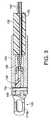
- FIG. 3is a sectional view of the distal end of the treatment tool observed from the direction indicated by the arrow A in FIG. 2 ;
- FIG. 4is a sectional view of the inserting portion of the treatment tool taken along a line IV-IV in FIG. 2 .
- FIG. 1schematically shows a bipolar high frequency treatment tool 100 according to an embodiment of the invention connected to a high frequency power supply 200 .
- the treatment tool 100includes an operating portion 102 and an inserting portion 104 connected to the distal end of the operating portion 102 .
- the inserting portion 104is provided in a form and size that allows it to be introduced into a body cavity through an accessory channel of an endoscope (not shown).
- the inserting portion 104includes an elongated and flexible tube 106 , and a pair of conductive wires 108 (only one is shown) slidably passed through the tube 106 .
- the tube 106is made of insulating material such as poly-tetrafluoro-ethylene (PTFE) or silicone resin.
- PTFEpoly-tetrafluoro-ethylene
- silicone resinsilicone resin
- An electrode assembly 109is mounted to the distal end of the inserting portion 104 .
- the electrode assembly 109includes an end effector, or a pair of electrodes 110 that are connected to the conductive wires 108 .
- the operating portion 102includes a cylindrical portion 112 and a rod portion 114 slidably inserted into the cylindrical portion 112 .
- the cylindrical portion 112has a circumferential groove 112 a at a proximal end thereof.
- a user of the treatment tool 100can hold the operating portion 112 by pinching it at the groove 112 a with his index finger and long finger.
- the rod portion 114has a ring 114 a into which the user can insert his thumb to slide the rod portion 114 within the cylindrical portion 112 back and forth.
- the rod portion 114is connected with the pair of wires 108 in the cylindrical portion 112 such that the wires 108 retract and advance within the tube 106 as the rod portion 114 is moved back and forth with respect to the cylindrical portion 112 .
- the conductive wires 108are detachably connected to power supply lines of the high frequency power supply 200 via a pair of connectors 116 provided to the side surface of the cylindrical portion 112 .
- One of the conductive wires 108is connected to the positive terminal of the power supply 200 and the other to the negative terminal.
- FIG. 2is sectional side view of the distal end of the treatment tool 100 shown in FIG. 1
- FIG. 3is a sectional view of the distal end of the treatment tool 100 observed from the direction indicated by the arrow A in FIG. 2
- FIG. 4is a sectional view of the inserting portion 104 of the treatment tool 100 taken along a line IV-IV in FIG. 2 . Note that FIGS. 2 and 3 are drawn as a composite view combining cross sectional views at various positions.
- the tube 106is an elongated and flexible tube made of insulating material. As shown in FIG. 4 , the tube 106 is provided with a pair of guide channels 120 extending over the length of the tube 106 . The wires 108 are passed through respective ones of the pair of guide channels 120 from the proximal end of the tube 106 to the distal end. Thus, the wires 108 are isolated from each other in the tube 106 .
- the guide channels 120are formed symmetrically with respect to the longitudinal center axis 106 a of the tube 106 and spaced apart from each other for about 0.5 mm. This arrangement ensures good insulation between the wires 106 .
- the conductive wires 106are naked twisted stainless steel wires, that is, the wires are not covered with any layers including insulating layers. The use of such naked wires allows cost reduction of the treatment tool 100 .
- the guide channels 120 of the tube 106are formed to have inner diameters slightly larger than the outer diameters of the wires 106 so that the wires can smoothly slide within respective guide channels.
- the guide channelsare formed to have an inner diameter small enough to prevent the wires therein from buckling or folding within the guide channels as the wires are advanced and retracted within the guide channels 120 .
- the inner diameter of each guide channel 120is about 0.1 to 0.3 mm larger than the outer diameter of each wire 106 .
- a supporting member (clevis) 130is attached to the distal end of the tube 106 .
- the supporting memberis made of insulating material such as rigid plastic or ceramic, and is provided with a slit 132 having a constant width.
- a pair of metal (stainless steel) pins 134is fixed to the distal portion of the supporting member 130 so as to cross the slit 132 .
- the pins 134are arranged spaced apart from each other and also parallel to each other.
- the pins 134are also arranged such that a center axis 130 a of the supporting member 130 passes through between the pins 134 .
- the pair of elongated electrodes 110is pivotably mounted on the pair of pins 134 so as to open and close like a pair of pincers. Each electrode 110 is mounted on a different one of the pins 134 to avoid making a short circuit through the pins 134 .
- each electrode 110is placed outside the slit 132 and formed into a cup like shape.
- the electrodescome into contact to each other only at the cup like portions 110 a with the concave sides thereof facing to each other.
- each electrode 110 a of each electrode 110is not limited to above-mentioned one.
- the distal portion of each electrode 110may be also formed into a rod like shape or any other shape.
- An insulating spacer 140is placed in the slit 132 of the supporting member 130 between the pair of electrodes 110 so as to electrically isolate the electrodes from each other within the slit 132 .
- the spacer 140has a pair of through holes 142 (only one is shown in FIGS. 3 and 4 ) and is supported by the pins 134 passed through respective through holes 142 .
- a through hole 110 cis formed in a vicinity of the proximal end of each electrode 110 .
- the tip end of each wire 106is passed through the through hole 110 c of the corresponding electrode 110 to be coupled therewith.
- each electrode 110is slightly bent so that each electrode 110 easily rotate about the corresponding pin 134 when the corresponding wire 108 is advanced/retracted along the guide channel 120 of the tube 106 by manipulating the operating portion 102 .
- the inserting portion 104 of treatment tool 100 configured as aboveis introduced into a body cavity such as a stomach through an endoscope and the electrodes 110 are located in the vicinity of a target portion of the mucosa.
- the operating portion 102 of the treatment tool 100is operated such that the pair of conductive wires 108 is slid forwards within the sheath 106 and swing the electrodes 110 to the open position. Then, the electrodes 110 are moved by the endoscope such that the target portion of the mucosa is located between the electrodes 110 .
- the pair of conductive wires 108are retracted by pulling back the rod portion 114 with respect to the cylindrical portion 112 to move the electrodes 110 to the closed position and thereby grasping the target mucosa.
- a high frequency electrical poweris supplied from the power supply 200 to the electrodes 110 via the conductive wires 108 .
- a high frequency currentflows through the mucosa placed between the electrodes 110 and coagulates the mucosa.
Landscapes
- Health & Medical Sciences (AREA)
- Surgery (AREA)
- Engineering & Computer Science (AREA)
- Life Sciences & Earth Sciences (AREA)
- Biomedical Technology (AREA)
- Molecular Biology (AREA)
- Nuclear Medicine, Radiotherapy & Molecular Imaging (AREA)
- Plasma & Fusion (AREA)
- Physics & Mathematics (AREA)
- Heart & Thoracic Surgery (AREA)
- Medical Informatics (AREA)
- Otolaryngology (AREA)
- Animal Behavior & Ethology (AREA)
- General Health & Medical Sciences (AREA)
- Public Health (AREA)
- Veterinary Medicine (AREA)
- Surgical Instruments (AREA)
- Endoscopes (AREA)
Abstract
Description
Claims (15)
Applications Claiming Priority (2)
| Application Number | Priority Date | Filing Date | Title |
|---|---|---|---|
| JP2002-219380 | 2002-07-29 | ||
| JP2002219380AJP4420593B2 (en) | 2002-07-29 | 2002-07-29 | Bipolar high-frequency treatment instrument for endoscope |
Publications (2)
| Publication Number | Publication Date |
|---|---|
| US20040019352A1 US20040019352A1 (en) | 2004-01-29 |
| US7326209B2true US7326209B2 (en) | 2008-02-05 |
Family
ID=30437666
Family Applications (1)
| Application Number | Title | Priority Date | Filing Date |
|---|---|---|---|
| US10/619,563Expired - LifetimeUS7326209B2 (en) | 2002-07-29 | 2003-07-16 | Bipolar high frequency treatment tool for endoscope |
Country Status (3)
| Country | Link |
|---|---|
| US (1) | US7326209B2 (en) |
| JP (1) | JP4420593B2 (en) |
| DE (1) | DE10334525B4 (en) |
Cited By (13)
| Publication number | Priority date | Publication date | Assignee | Title |
|---|---|---|---|---|
| US20040260198A1 (en)* | 2003-06-18 | 2004-12-23 | Elliott Rothberg | Endoscopic instruments |
| US20050043758A1 (en)* | 2003-08-18 | 2005-02-24 | Scimed Life Systems, Inc. | Endoscopic medical instrument and related methods of use |
| US20060217828A1 (en)* | 2002-10-23 | 2006-09-28 | Hicken Wendell T | Music searching system and method |
| US20070198011A1 (en)* | 2006-02-20 | 2007-08-23 | Pentax Corporation | Bipolar high-frequency treatment tool for endoscope |
| US20110112568A1 (en)* | 2009-08-28 | 2011-05-12 | The Penn State Research Foundation | Surgical tool |
| US8317726B2 (en) | 2005-05-13 | 2012-11-27 | Boston Scientific Scimed, Inc. | Biopsy forceps assemblies |
| US8939345B2 (en) | 2009-05-29 | 2015-01-27 | Ntn Corporation | Remote-controlled actuator |
| WO2015099335A1 (en)* | 2013-12-27 | 2015-07-02 | 아이메디컴(주) | High-frequency electrotherapeutic device |
| US9446456B2 (en) | 2008-09-11 | 2016-09-20 | Ntn Corporation | Remote-controlled actuator |
| US9681857B2 (en) | 2003-06-18 | 2017-06-20 | Boston Scientific Scimed, Inc. | Endoscopic instruments and methods of manufacture |
| USD904611S1 (en) | 2018-10-10 | 2020-12-08 | Bolder Surgical, Llc | Jaw design for a surgical instrument |
| USD934423S1 (en) | 2020-09-11 | 2021-10-26 | Bolder Surgical, Llc | End effector for a surgical device |
| USD1046129S1 (en) | 2021-04-14 | 2024-10-08 | Bolder Surgical, Llc | End effector for a surgical instrument |
Families Citing this family (25)
| Publication number | Priority date | Publication date | Assignee | Title |
|---|---|---|---|---|
| WO2005016163A1 (en)* | 2003-08-19 | 2005-02-24 | River Seiko Medical Limited Company | Bipolar high-frequency instrument for medical treatment |
| JP4436698B2 (en)* | 2004-02-25 | 2010-03-24 | オリンパス株式会社 | High frequency treatment tool |
| US7377941B2 (en)* | 2004-06-29 | 2008-05-27 | Micardia Corporation | Adjustable cardiac valve implant with selective dimensional adjustment |
| US20070282330A1 (en)* | 2006-05-30 | 2007-12-06 | Pentax Corporation | Bipolar high-frequency treatment tool for an endoscope |
| US20070282331A1 (en)* | 2006-05-30 | 2007-12-06 | Pentax Corporation | Bipolar high-frequency incision tool for an endoscope |
| US20090216322A1 (en)* | 2007-08-10 | 2009-08-27 | Le Le | Adjustable annuloplasty ring and activation system |
| US9204923B2 (en)* | 2008-07-16 | 2015-12-08 | Intuitive Surgical Operations, Inc. | Medical instrument electronically energized using drive cables |
| JP5371309B2 (en)* | 2008-07-23 | 2013-12-18 | オリンパスメディカルシステムズ株式会社 | High frequency treatment tool |
| JP2010142279A (en)* | 2008-12-16 | 2010-07-01 | Olympus Medical Systems Corp | Treatment instrument |
| BRPI1012999A2 (en)* | 2009-05-21 | 2018-01-16 | Sumitomo Bakelite Co | "high frequency treatment instrument" |
| JP5388701B2 (en)* | 2009-05-29 | 2014-01-15 | Ntn株式会社 | Remote control type actuator |
| JP5388702B2 (en)* | 2009-05-29 | 2014-01-15 | Ntn株式会社 | Remote control type actuator |
| CN102413786B (en)* | 2010-01-18 | 2014-07-02 | 奥林巴斯医疗株式会社 | Treatment device for endoscope |
| US9339341B2 (en) | 2010-02-08 | 2016-05-17 | Intuitive Surgical Operations, Inc. | Direct pull surgical gripper |
| US9333002B2 (en)* | 2010-11-19 | 2016-05-10 | Covidien Lp | Apparatus for performing an electrosurgical procedure |
| DE102012100040A1 (en) | 2012-01-04 | 2013-07-04 | Aesculap Ag | Electrosurgical instrument and jaw part for this |
| DE102012101257A1 (en)* | 2012-02-16 | 2013-08-22 | Aesculap Ag | Electrosurgical instrument |
| WO2015093602A1 (en) | 2013-12-20 | 2015-06-25 | オリンパス株式会社 | Guide member for flexible manipulator, and flexible manipulator |
| CN103815961B (en)* | 2014-02-28 | 2017-11-21 | 中国人民解放军第二军医大学 | A kind of coagulation probe through bronchoscope |
| CN107249491A (en) | 2015-06-01 | 2017-10-13 | 奥林巴斯株式会社 | Medical manipulator |
| WO2017175373A1 (en) | 2016-04-08 | 2017-10-12 | オリンパス株式会社 | Flexible manipulator |
| JP6616498B2 (en) | 2016-04-28 | 2019-12-04 | オリンパス株式会社 | Sheath and manipulator for flexible manipulator |
| WO2018216117A1 (en) | 2017-05-23 | 2018-11-29 | オリンパス株式会社 | Flexible tube for medical use and flexible manipulator for medical use |
| WO2019030848A1 (en) | 2017-08-09 | 2019-02-14 | オリンパス株式会社 | Treatment tool |
| WO2019199827A1 (en) | 2018-04-10 | 2019-10-17 | Intuitive Surgical Operations, Inc. | Articulable medical devices having flexible wire routing |
Citations (20)
| Publication number | Priority date | Publication date | Assignee | Title |
|---|---|---|---|---|
| US5035696A (en)* | 1990-02-02 | 1991-07-30 | Everest Medical Corporation | Electrosurgical instrument for conducting endoscopic retrograde sphincterotomy |
| US5258006A (en)* | 1992-08-21 | 1993-11-02 | Everest Medical Corporation | Bipolar electrosurgical forceps |
| US5323768A (en) | 1991-04-22 | 1994-06-28 | Olympus Optical Co., Ltd. | Diathermic dissector with a bifurcation having substantially the same cross-sectional area as a lumen for guiding a wire |
| US5482054A (en)* | 1990-05-10 | 1996-01-09 | Symbiosis Corporation | Edoscopic biopsy forceps devices with selective bipolar cautery |
| US5536248A (en)* | 1992-05-11 | 1996-07-16 | Arrow Precision Products, Inc. | Method and apparatus for electrosurgically obtaining access to the biliary tree and placing a stent therein |
| JP2528223B2 (en) | 1991-09-12 | 1996-08-28 | オリンパス光学工業株式会社 | High Frequency Incision Tool for Endoscope |
| US5603711A (en)* | 1995-01-20 | 1997-02-18 | Everest Medical Corp. | Endoscopic bipolar biopsy forceps |
| US5697949A (en)* | 1995-05-18 | 1997-12-16 | Symbiosis Corporation | Small diameter endoscopic instruments |
| US5762613A (en)* | 1996-05-07 | 1998-06-09 | Spectrascience, Inc. | Optical biopsy forceps |
| JPH10165359A (en) | 1996-12-12 | 1998-06-23 | Asahi Optical Co Ltd | Endoscope treatment tool |
| US5820630A (en)* | 1996-10-22 | 1998-10-13 | Annex Medical, Inc. | Medical forceps jaw assembly |
| US5827278A (en)* | 1997-05-20 | 1998-10-27 | Cordis Webster, Inc. | Deflectable tip electrode catheter with nylon stiffener and compression coil |
| JPH11113918A (en) | 1997-10-15 | 1999-04-27 | Olympus Optical Co Ltd | Forceps |
| US5908437A (en)* | 1996-11-01 | 1999-06-01 | Kai R&D Center Co., Ltd. | Remotely actuated surgical instrument |
| JPH11342135A (en) | 1998-06-01 | 1999-12-14 | Olympus Optical Co Ltd | Treatment device |
| JP2000139942A (en) | 1998-11-10 | 2000-05-23 | Olympus Optical Co Ltd | High-frequency treating instrument |
| JP3086166B2 (en) | 1996-02-05 | 2000-09-11 | オリンパス光学工業株式会社 | High frequency incision device for endoscope |
| JP2000271128A (en) | 1999-03-29 | 2000-10-03 | Asahi Optical Co Ltd | High-frequency biopsy forceps for endoscope |
| US20020123667A1 (en) | 2001-03-01 | 2002-09-05 | Asahi Kogaku Kogyo Kabushiki Kaisha | Bipolar forceps for endoscopes |
| US20030191465A1 (en)* | 2002-04-09 | 2003-10-09 | Pentax Corporation | Electrosurgicalscissors for endoscopic mucosal resection |
Family Cites Families (3)
| Publication number | Priority date | Publication date | Assignee | Title |
|---|---|---|---|---|
| US123667A (en)* | 1872-02-13 | Improvement in machines for cutting out and flanging metallic disks | ||
| DE4490796T1 (en)* | 1993-02-11 | 1996-01-11 | Symbiosis Corp | Forceps with selective bipolar cauterization for endoscopic biopsy |
| US5352222A (en)* | 1994-03-15 | 1994-10-04 | Everest Medical Corporation | Surgical scissors with bipolar coagulation feature |
- 2002
- 2002-07-29JPJP2002219380Apatent/JP4420593B2/ennot_activeExpired - Fee Related
- 2003
- 2003-07-16USUS10/619,563patent/US7326209B2/ennot_activeExpired - Lifetime
- 2003-07-29DEDE10334525.6Apatent/DE10334525B4/ennot_activeExpired - Lifetime
Patent Citations (23)
| Publication number | Priority date | Publication date | Assignee | Title |
|---|---|---|---|---|
| US5035696A (en)* | 1990-02-02 | 1991-07-30 | Everest Medical Corporation | Electrosurgical instrument for conducting endoscopic retrograde sphincterotomy |
| US5482054A (en)* | 1990-05-10 | 1996-01-09 | Symbiosis Corporation | Edoscopic biopsy forceps devices with selective bipolar cautery |
| US5323768A (en) | 1991-04-22 | 1994-06-28 | Olympus Optical Co., Ltd. | Diathermic dissector with a bifurcation having substantially the same cross-sectional area as a lumen for guiding a wire |
| JP2528223B2 (en) | 1991-09-12 | 1996-08-28 | オリンパス光学工業株式会社 | High Frequency Incision Tool for Endoscope |
| US5536248A (en)* | 1992-05-11 | 1996-07-16 | Arrow Precision Products, Inc. | Method and apparatus for electrosurgically obtaining access to the biliary tree and placing a stent therein |
| US5258006A (en)* | 1992-08-21 | 1993-11-02 | Everest Medical Corporation | Bipolar electrosurgical forceps |
| US5603711A (en)* | 1995-01-20 | 1997-02-18 | Everest Medical Corp. | Endoscopic bipolar biopsy forceps |
| US5743906A (en)* | 1995-01-20 | 1998-04-28 | Everest Medical Corporation | Endoscopic bipolar biopsy forceps |
| US5697949A (en)* | 1995-05-18 | 1997-12-16 | Symbiosis Corporation | Small diameter endoscopic instruments |
| JP3086166B2 (en) | 1996-02-05 | 2000-09-11 | オリンパス光学工業株式会社 | High frequency incision device for endoscope |
| US5762613A (en)* | 1996-05-07 | 1998-06-09 | Spectrascience, Inc. | Optical biopsy forceps |
| US5820630A (en)* | 1996-10-22 | 1998-10-13 | Annex Medical, Inc. | Medical forceps jaw assembly |
| US5908437A (en)* | 1996-11-01 | 1999-06-01 | Kai R&D Center Co., Ltd. | Remotely actuated surgical instrument |
| JPH10165359A (en) | 1996-12-12 | 1998-06-23 | Asahi Optical Co Ltd | Endoscope treatment tool |
| US5827278A (en)* | 1997-05-20 | 1998-10-27 | Cordis Webster, Inc. | Deflectable tip electrode catheter with nylon stiffener and compression coil |
| JPH11113918A (en) | 1997-10-15 | 1999-04-27 | Olympus Optical Co Ltd | Forceps |
| JPH11342135A (en) | 1998-06-01 | 1999-12-14 | Olympus Optical Co Ltd | Treatment device |
| JP2000139942A (en) | 1998-11-10 | 2000-05-23 | Olympus Optical Co Ltd | High-frequency treating instrument |
| JP2000271128A (en) | 1999-03-29 | 2000-10-03 | Asahi Optical Co Ltd | High-frequency biopsy forceps for endoscope |
| US20020123667A1 (en) | 2001-03-01 | 2002-09-05 | Asahi Kogaku Kogyo Kabushiki Kaisha | Bipolar forceps for endoscopes |
| JP2002253570A (en) | 2001-03-01 | 2002-09-10 | Asahi Optical Co Ltd | Bipolar high frequency treatment tool for endoscope |
| US6767349B2 (en)* | 2001-03-01 | 2004-07-27 | Pentax Corporation | Bipolar forceps for endoscopes |
| US20030191465A1 (en)* | 2002-04-09 | 2003-10-09 | Pentax Corporation | Electrosurgicalscissors for endoscopic mucosal resection |
Cited By (18)
| Publication number | Priority date | Publication date | Assignee | Title |
|---|---|---|---|---|
| US20060217828A1 (en)* | 2002-10-23 | 2006-09-28 | Hicken Wendell T | Music searching system and method |
| US20040260198A1 (en)* | 2003-06-18 | 2004-12-23 | Elliott Rothberg | Endoscopic instruments |
| US9681857B2 (en) | 2003-06-18 | 2017-06-20 | Boston Scientific Scimed, Inc. | Endoscopic instruments and methods of manufacture |
| US8469993B2 (en) | 2003-06-18 | 2013-06-25 | Boston Scientific Scimed, Inc. | Endoscopic instruments |
| US20050043758A1 (en)* | 2003-08-18 | 2005-02-24 | Scimed Life Systems, Inc. | Endoscopic medical instrument and related methods of use |
| US7951165B2 (en) | 2003-08-18 | 2011-05-31 | Boston Scientific Scimed, Inc. | Endoscopic medical instrument and related methods of use |
| US8317726B2 (en) | 2005-05-13 | 2012-11-27 | Boston Scientific Scimed, Inc. | Biopsy forceps assemblies |
| US8672859B2 (en) | 2005-05-13 | 2014-03-18 | Boston Scientific Scimed, Inc. | Biopsy forceps assemblies |
| US20070198011A1 (en)* | 2006-02-20 | 2007-08-23 | Pentax Corporation | Bipolar high-frequency treatment tool for endoscope |
| US8480670B2 (en) | 2006-02-20 | 2013-07-09 | Hoya Corporation | Bipolar high-frequency treatment tool for endoscope |
| US9446456B2 (en) | 2008-09-11 | 2016-09-20 | Ntn Corporation | Remote-controlled actuator |
| US8939345B2 (en) | 2009-05-29 | 2015-01-27 | Ntn Corporation | Remote-controlled actuator |
| US20110112568A1 (en)* | 2009-08-28 | 2011-05-12 | The Penn State Research Foundation | Surgical tool |
| US8382791B2 (en)* | 2009-08-28 | 2013-02-26 | The Penn State Research Foundation | Surgical tool |
| WO2015099335A1 (en)* | 2013-12-27 | 2015-07-02 | 아이메디컴(주) | High-frequency electrotherapeutic device |
| USD904611S1 (en) | 2018-10-10 | 2020-12-08 | Bolder Surgical, Llc | Jaw design for a surgical instrument |
| USD934423S1 (en) | 2020-09-11 | 2021-10-26 | Bolder Surgical, Llc | End effector for a surgical device |
| USD1046129S1 (en) | 2021-04-14 | 2024-10-08 | Bolder Surgical, Llc | End effector for a surgical instrument |
Also Published As
| Publication number | Publication date |
|---|---|
| US20040019352A1 (en) | 2004-01-29 |
| DE10334525A1 (en) | 2004-02-12 |
| DE10334525B4 (en) | 2015-08-27 |
| JP2004057454A (en) | 2004-02-26 |
| JP4420593B2 (en) | 2010-02-24 |
Similar Documents
| Publication | Publication Date | Title |
|---|---|---|
| US7326209B2 (en) | Bipolar high frequency treatment tool for endoscope | |
| US6190386B1 (en) | Electrosurgical forceps with needle electrodes | |
| US6964662B2 (en) | Endoscopic forceps instrument | |
| US8480670B2 (en) | Bipolar high-frequency treatment tool for endoscope | |
| US6953430B2 (en) | Pincerlike instrument for endoscope | |
| CN113616320B (en) | Electrosurgical instrument | |
| US6019758A (en) | Endoscopic bipolar multiple sample bioptome | |
| US6767349B2 (en) | Bipolar forceps for endoscopes | |
| US4905691A (en) | Polypectome snare with bipolar electrodes | |
| EP1728462A3 (en) | Instrument for endoscope and instrument system for endoscope | |
| US6969389B2 (en) | Bipolar hemostatic forceps for an endoscope | |
| US7699836B2 (en) | Treatment tool for endoscope | |
| WO1997024995A9 (en) | Endoscopic bipolar multiple sample bioptome | |
| EP2386255B1 (en) | Endoscope treatment instrument | |
| JP2003504109A (en) | Movable ablation electrode | |
| EP2022430B1 (en) | Endoscopic treatment tool | |
| US7354439B2 (en) | Treatment tool for endoscope having end effector operating like pincers | |
| US20030191465A1 (en) | Electrosurgicalscissors for endoscopic mucosal resection | |
| JPH055106U (en) | High frequency treatment tool for endoscope | |
| US6951560B1 (en) | Bipolar high frequency treatment tool for an endoscope | |
| JP2000271128A (en) | High-frequency biopsy forceps for endoscope | |
| EP1847231B1 (en) | Soft bipolar forceps | |
| JP5312868B2 (en) | Endoscopic treatment tool | |
| JP4105319B2 (en) | Endoscope operation part | |
| JP4459692B2 (en) | Bipolar high-frequency treatment instrument for endoscope |
Legal Events
| Date | Code | Title | Description |
|---|---|---|---|
| AS | Assignment | Owner name:PENTAX CORPORATION, JAPAN Free format text:ASSIGNMENT OF ASSIGNORS INTEREST;ASSIGNOR:KIDOOKA, SATOSHI;REEL/FRAME:014283/0322 Effective date:20030710 | |
| FEPP | Fee payment procedure | Free format text:PAYOR NUMBER ASSIGNED (ORIGINAL EVENT CODE: ASPN); ENTITY STATUS OF PATENT OWNER: LARGE ENTITY | |
| STCF | Information on status: patent grant | Free format text:PATENTED CASE | |
| FPAY | Fee payment | Year of fee payment:4 | |
| FPAY | Fee payment | Year of fee payment:8 | |
| AS | Assignment | Owner name:HOYA CORPORATION, JAPAN Free format text:MERGER;ASSIGNOR:PENTAX CORPORATION;REEL/FRAME:042114/0463 Effective date:20080407 | |
| AS | Assignment | Owner name:HOYA CORPORATION, JAPAN Free format text:CHANGE OF ADDRESS OF ASSIGNEE;ASSIGNOR:HOYA CORPORATION;REEL/FRAME:042424/0318 Effective date:20160401 | |
| MAFP | Maintenance fee payment | Free format text:PAYMENT OF MAINTENANCE FEE, 12TH YEAR, LARGE ENTITY (ORIGINAL EVENT CODE: M1553); ENTITY STATUS OF PATENT OWNER: LARGE ENTITY Year of fee payment:12 |