US7326199B2 - System and method for flexible architecture for dermatologic treatments utilizing multiple light sources - Google Patents
System and method for flexible architecture for dermatologic treatments utilizing multiple light sourcesDownload PDFInfo
- Publication number
- US7326199B2 US7326199B2US10/788,821US78882104AUS7326199B2US 7326199 B2US7326199 B2US 7326199B2US 78882104 AUS78882104 AUS 78882104AUS 7326199 B2US7326199 B2US 7326199B2
- Authority
- US
- United States
- Prior art keywords
- hand piece
- light source
- holding area
- power supply
- light
- Prior art date
- Legal status (The legal status is an assumption and is not a legal conclusion. Google has not performed a legal analysis and makes no representation as to the accuracy of the status listed.)
- Active, expires
Links
- 238000011282treatmentMethods0.000titleclaimsabstractdescription68
- 238000000034methodMethods0.000titleclaimsabstractdescription29
- 230000002500effect on skinEffects0.000claimsabstractdescription3
- 238000003825pressingMethods0.000claimsdescription17
- 230000004044responseEffects0.000claimsdescription17
- 230000004913activationEffects0.000claimsdescription9
- 238000001514detection methodMethods0.000claimsdescription9
- 239000000835fiberSubstances0.000claimsdescription9
- 230000008878couplingEffects0.000claimsdescription5
- 238000010168coupling processMethods0.000claimsdescription5
- 238000005859coupling reactionMethods0.000claimsdescription5
- 230000003213activating effectEffects0.000claims2
- 238000005086pumpingMethods0.000claims2
- 238000013532laser treatmentMethods0.000claims1
- 238000007726management methodMethods0.000description53
- 230000003287optical effectEffects0.000description13
- 238000013461designMethods0.000description11
- 239000002826coolantSubstances0.000description8
- 230000008901benefitEffects0.000description6
- 239000003990capacitorSubstances0.000description5
- 238000003491arrayMethods0.000description4
- 230000006870functionEffects0.000description4
- 230000003902lesionEffects0.000description4
- 230000008859changeEffects0.000description3
- 230000001276controlling effectEffects0.000description3
- 238000011277treatment modalityMethods0.000description3
- 230000009286beneficial effectEffects0.000description2
- 238000001816coolingMethods0.000description2
- 239000012809cooling fluidSubstances0.000description2
- 238000004146energy storageMethods0.000description2
- 238000010304firingMethods0.000description2
- 238000010438heat treatmentMethods0.000description2
- 230000001939inductive effectEffects0.000description2
- 206010024217lentigoDiseases0.000description2
- 238000001208nuclear magnetic resonance pulse sequenceMethods0.000description2
- 239000013307optical fiberSubstances0.000description2
- 239000000049pigmentSubstances0.000description2
- 230000009467reductionEffects0.000description2
- 239000004065semiconductorSubstances0.000description2
- 230000002792vascularEffects0.000description2
- 102000008186CollagenHuman genes0.000description1
- 108010035532CollagenProteins0.000description1
- 208000020564Eye injuryDiseases0.000description1
- 208000000114Pain ThresholdDiseases0.000description1
- 208000012641Pigmentation diseaseDiseases0.000description1
- XAGFODPZIPBFFR-UHFFFAOYSA-NaluminiumChemical compound[Al]XAGFODPZIPBFFR-UHFFFAOYSA-N0.000description1
- 229910052782aluminiumInorganic materials0.000description1
- 238000013459approachMethods0.000description1
- 230000000903blocking effectEffects0.000description1
- 230000001427coherent effectEffects0.000description1
- 229920001436collagenPolymers0.000description1
- 230000000295complement effectEffects0.000description1
- 230000003247decreasing effectEffects0.000description1
- 230000000994depressogenic effectEffects0.000description1
- 238000011161developmentMethods0.000description1
- 238000005516engineering processMethods0.000description1
- 238000012423maintenanceMethods0.000description1
- 239000000463materialSubstances0.000description1
- 230000013011matingEffects0.000description1
- 238000012544monitoring processMethods0.000description1
- 238000011369optimal treatmentMethods0.000description1
- 230000037040pain thresholdEffects0.000description1
- 230000019612pigmentationEffects0.000description1
- 230000008569processEffects0.000description1
- 230000005855radiationEffects0.000description1
- 230000001105regulatory effectEffects0.000description1
- 229910052594sapphireInorganic materials0.000description1
- 239000010980sapphireSubstances0.000description1
- 230000003595spectral effectEffects0.000description1
- 238000001228spectrumMethods0.000description1
- 230000001225therapeutic effectEffects0.000description1
- 238000003079width controlMethods0.000description1
- 229910052724xenonInorganic materials0.000description1
- FHNFHKCVQCLJFQ-UHFFFAOYSA-Nxenon atomChemical compound[Xe]FHNFHKCVQCLJFQ-UHFFFAOYSA-N0.000description1
Images


Classifications
- A—HUMAN NECESSITIES
- A61—MEDICAL OR VETERINARY SCIENCE; HYGIENE
- A61B—DIAGNOSIS; SURGERY; IDENTIFICATION
- A61B18/00—Surgical instruments, devices or methods for transferring non-mechanical forms of energy to or from the body
- A61B18/18—Surgical instruments, devices or methods for transferring non-mechanical forms of energy to or from the body by applying electromagnetic radiation, e.g. microwaves
- A61B18/20—Surgical instruments, devices or methods for transferring non-mechanical forms of energy to or from the body by applying electromagnetic radiation, e.g. microwaves using laser
- A61B18/203—Surgical instruments, devices or methods for transferring non-mechanical forms of energy to or from the body by applying electromagnetic radiation, e.g. microwaves using laser applying laser energy to the outside of the body
- A—HUMAN NECESSITIES
- A61—MEDICAL OR VETERINARY SCIENCE; HYGIENE
- A61B—DIAGNOSIS; SURGERY; IDENTIFICATION
- A61B17/00—Surgical instruments, devices or methods
- A61B2017/00017—Electrical control of surgical instruments
- A61B2017/00199—Electrical control of surgical instruments with a console, e.g. a control panel with a display
- A—HUMAN NECESSITIES
- A61—MEDICAL OR VETERINARY SCIENCE; HYGIENE
- A61B—DIAGNOSIS; SURGERY; IDENTIFICATION
- A61B18/00—Surgical instruments, devices or methods for transferring non-mechanical forms of energy to or from the body
- A61B2018/00315—Surgical instruments, devices or methods for transferring non-mechanical forms of energy to or from the body for treatment of particular body parts
- A61B2018/00452—Skin
- A—HUMAN NECESSITIES
- A61—MEDICAL OR VETERINARY SCIENCE; HYGIENE
- A61B—DIAGNOSIS; SURGERY; IDENTIFICATION
- A61B18/00—Surgical instruments, devices or methods for transferring non-mechanical forms of energy to or from the body
- A61B18/18—Surgical instruments, devices or methods for transferring non-mechanical forms of energy to or from the body by applying electromagnetic radiation, e.g. microwaves
- A61B2018/1807—Surgical instruments, devices or methods for transferring non-mechanical forms of energy to or from the body by applying electromagnetic radiation, e.g. microwaves using light other than laser radiation
- A—HUMAN NECESSITIES
- A61—MEDICAL OR VETERINARY SCIENCE; HYGIENE
- A61B—DIAGNOSIS; SURGERY; IDENTIFICATION
- A61B18/00—Surgical instruments, devices or methods for transferring non-mechanical forms of energy to or from the body
- A61B18/18—Surgical instruments, devices or methods for transferring non-mechanical forms of energy to or from the body by applying electromagnetic radiation, e.g. microwaves
- A61B18/20—Surgical instruments, devices or methods for transferring non-mechanical forms of energy to or from the body by applying electromagnetic radiation, e.g. microwaves using laser
- A61B2018/208—Surgical instruments, devices or methods for transferring non-mechanical forms of energy to or from the body by applying electromagnetic radiation, e.g. microwaves using laser with multiple treatment beams not sharing a common path, e.g. non-axial or parallel
Definitions
- the present inventionrelates to a system and method of providing for a range of different dermatologic treatments using different light sources.
- High power laser and light source medical treatment devicesare generally designed with a power supply, light delivery system and user interface which are optimized for the particular type of laser or light source. A consequence is that manufacturers of such systems develop new consoles for each new laser or light source or treatment modality. Systems compatible with multiple light sources generally make major design compromises. A frequent situation is that a multiple modality laser/light treatment platform may be able to provide for different treatments from different light sources, but in general the system will require a number of compromises, such that none of the different light sources are operated in a manner which allows them to provide an optimal treatment for the given light source.
- FIG. 1shows a view of an embodiment of a system herein.
- FIG. 2Ashows a view of an embodiment of a hand piece management device of a system herein.
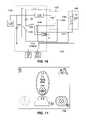
- FIG. 2Bshows a view of an embodiment of a hand piece management device with hand pieces shown in seated positions.
- FIG. 3shows a perspective view of an embodiment of a system herein.
- FIG. 4shows a screenshot from a display of an embodiment herein.
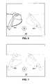
- FIG. 5shows a screenshot from a display of an embodiment herein.
- FIG. 6shows a screenshot from a display of an embodiment herein.
- FIG. 7shows a screenshot from a display of an embodiment herein.
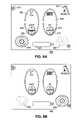
- FIG. 8A-8Bshow screenshots from a display of an embodiment herein.
- FIG. 9A-9Bshow screenshots from a display of an embodiment herein.
- FIG. 10shows a screenshot from a display of an embodiment herein.
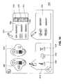
- FIG. 11shows an embodiment of a system herein.
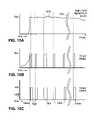
- FIG. 12shows pulses of light energy output by a flashlamp of an embodiment herein.
- FIG. 13shows pulses of light energy output by a flashlamp of an embodiment herein.
- FIG. 14shows a method of an embodiment herein.
- FIG. 15shows a current applied to a filament light source, and power output by a filament light source.
- FIG. 16shows an embodiment of a system herein.
- FIG. 17shows screen shot from a display of an embodiment herein.
- An exemplary embodiment hereinprovides a dermatologic laser/light source treatment system which provides for a great deal of flexibility with respect to the types of light sources employed.
- the systemprovides for a hand piece management unit which provides for holding different hand pieces which provide light treatment from different light sources.
- an embodiment of the systemincludes a versatile high voltage power supply which allows for the operation of multiple diverse types of light sources.
- An embodiment of the system hereinalso includes a detection circuit with sensors (which sense when one of the hand pieces have been removed from holding areas of the hand piece management unit) safety functions and a user interface that allows for easily switching between operation and control of the different light sources.
- An embodiment of the system hereinincludes a flexible and versatile power supply which can drive a wide range of different light sources such as lasers, flash lamps, filament light sources and LEDS, as well as a range of other possible light sources. Further, this power supply can output different amounts of electrical energy and different pulse widths to provide a wide range treatment variations.
- a general overview of the design of a system hereinwould include a main console.
- This main consolecould include a frame of aluminum or other material, and side panels, and different components of the system would be secured inside the main console.
- the main consolecould house the high voltage power supply for driving the various types of light sources.
- Coupled to the consoleare different hand pieces which are used to apply the light treatments to the patient's skin.
- a light sourcecan be located in the hand piece itself, and electrical current can be delivered to the hand piece to cause the light source to generate light
- a different hand piececould provide for receiving laser light from a laser source which is housed inside the console itself.
- FIG. 1shows a system 100 , which provides a main console 200 .
- Main console 200houses an AC connection 12 and electrical mains which receives AC power from the AC connection and provides AC and DC power to the other elements of the system.
- the main console 200also includes a coolant system 120 , where a coolant system would typically include elements such as a coolant reservoir, pump and heat exchanger.
- a high voltage power supply (HVPS) 40which receives electrical energy from the electrical mains 10 , and outputs pulses of electrical energy to drive the different light sources.
- a controller unit 20which can include a software EEPROM and/or other elements such as a microcontroller, or possibly a programmable CPU, operates as system control electronics.
- the main consolecan also include a laser module 30 .
- a user interface module 210can be provided as an integral part of the main console 200 , or it can be a separate module which is coupled with the main console.
- the user interface module 210could be implemented using a number of different displays or user interfaces.
- the user panelcould be computer monitor, or a simple LED number display with turn knobs, or other user input devices.
- the user interfaceis implemented using a high resolution touch screen panel 80 , such as provided by Sharp Electronics, of Japan with US headquarters at Mahwah, N.J.
- the system 100also includes a hand piece management unit 220 .
- the hand piece management unitcan be coupled to the main console 200 by a support member 110 , which can be lowered or removed to transport the system 100 .
- the support member 110can include conducting signal lines where information derived from sensors (discussed in more detail below) in the hand piece management unit 220 can be transmitted to the control unit 20 in the main console 200 .
- the systemcould be designed to allow for more than two hand pieces. Additionally the system can be designed to allow for at least one of the hand pieces to be removed and replaced with a different hand piece which can deliver a different type of light treatment.
- the hand piece 60can provide a first type of light treatment
- the hand piece 62can provide a different type of light treatment.
- each of the hand piecesmounts in specified storage positions, or holding areas, in the hand piece management unit 220 . Additional aspects related to the holding of the hand pieces in the hand piece management unit 220 are discussed below.
- the system shown in FIG. 1provides for a flash lamp disposed in the hand piece device 60 , and a laser source 30 in the main console 200 provides laser light energy which is delivered via optic fiber 32 to the hand piece 62 . Both the flash lamp and the laser 30 are driven by a flexible pulse-width-modulating high voltage power supply 40 .
- Pending patent applicationU.S. application Ser. No. 10/135,981, filed Jan. 27, 2003 DERMATOLOGICAL TREATMENT FLASHLAMP DEVICE & METHOD
- HVPS 40includes a current direction control device which allows the power supply to direct electrical energy to either the laser module 30 or an external light source in the hand piece 60 .
- the HVPS 40can switch between driving a flash lamp, or other light source, including possibly a small flash lamp pumped laser, located in the hand piece device 60 and driving a laser 30 located in the main console 200 , without utilizing a power relay, by utilizing a simmer circuit.
- both light sources(the laser in the main console and the light source in the hand piece) are driven by a flashlamp.
- the light source in the hand piececould be either a small flashlamp driven laser, or the handpiece could provide for emitting light energy directly from the flashlamp to the treatment area.
- a simmer circuitoperates to provide a low amount of electrical power to the light source which is be activated.
- the operationis such that the control unit, after determining that one of the hand pieces has been removed from the hand piece management unit, will cause the simmer circuit to output low level current to the light source which corresponds to the hand piece which has been removed from the hand piece management unit. Further, the control unit operates such that if both hand pieces are removed from the hand piece management unit, then the control unit will not activate either light source, and will not cause the simmer circuit to output current to either of the light sources.
- High power electrical drive currentsare conducted from the HVPS 40 via electrical conducting lines 42 or 44 , depending on which light source is being driven, or stated differently depending on which treatment modality is active, the driving current will be transmitted by either 42 or 44 .
- a maximum of one light treatment modalityis available at a given time.
- the physical position of the hand pieces 60 and 62determines which modality may be accessed through the user interface module 210 .
- magnetic sensors embedded in rest positions 70 or 72send signals to a detection logic circuit 50 located in the hand piece management unit 220 . When the hand piece 60 is removed from position 70 , the logic circuit 50 will recognize that hand piece 60 is removed, and communicate this the central control unit 20 .
- the control unit 20will then control the operation of the system 100 such that the HVPS 40 can only drive the light source in the hand piece 60 , and HVPS input to the laser module 30 will be disabled. Conversely, if hand piece 62 is removed from position 72 , the external light source in the hand piece 62 is disabled and laser module 30 may be enabled. Should both hand pieces 60 and 62 be removed from positions 70 and 72 , neither light source will be driven by the HVPS 40 .
- the user input module 210will also indicate which hand piece is removed from a seated position in the hand piece management unit 220 , and for a hand piece which is removed from the seated position in the management unit 220 , the user interface module 210 will allow a user to access controls for the light source which is applied by the removed hand piece.
- the user interface module 210includes a user interface device such as a user-controlled touch screen display 90 , which is programmed to allow parameter selections only for the modality compatible with the hand piece which is removed from its seated position.
- the touch screen display 90can indicate that neither light source can be activated. Further aspects of the control of the system by the touch screen 90 are discussed in detail below.
- An example of the operationprovides that when the hand piece 60 is removed from position 70 , the light source in the hand piece 60 can be activated to generate light energy for a treatment application, in response to a user pressing a ready icon on the user interface, which puts the corresponding light source into a ready mode, and the user then steps on the detachable footswitch 230 .
- the laser source 30can be activated by pressing a ready icon and then stepping on the footswitch 230 .
- Laser module 30supplies laser light to hand piece 62 through optical fiber 32 when HVPS 40 applies energy to the laser module 30 .
- Aspects of different potential embodiments of hand pieces for delivering laser light delivered via an optical fiberare shown in U.S. Pat. No. 6,383,176 and U.S. Pat. No. 6,485,484, and both of the patents are incorporated herein by reference in their entirety.
- a cooling fluid from the coolant system 120 , control signals to and from control unit 20 , and thermo-electric cooler electrical drivelinesare routed to laser hand piece 62 through umbilical cable 132 .
- the laser module 30is an Nd:YAG laser outputting 1064 nm energy.
- Other flash lamp-pumped, or arc lamp pumped lasersmay be substituted, operating at other wavelengths or laser parameters for providing different dermatologic treatments.
- laser hand piece 62is designed to deliver laser light which is transmitted via an optic fiber
- external hand piece 60can be configured to deliver flash lamp light or other, even laser, light sources which are mounted inside the hand piece.
- Cooling fluid from the coolant system 120 , high voltage—high current electrical drive lines 42 , low voltage thermoelectric cooler electrical lines and control signal lines 43 and various I/O and sensing linescan be routed from the main console 200 to the hand piece 60 through an umbilical cable 130 .
- the hand piecedelivers filtered flash lamp light through a contact window.
- the external hand piece 60is coupled to the umbilical cable 130 which carries power, coolant and sensing lines, and the connector 230 operates to couple these lines with the elements of the main console 200 .
- This approach of providing a connector 230 and umbilical cable 130allows a variety of externally generated light sources to be used to apply different types of treatment, without the necessity of replacing the laser module 30 or altering the HVPS 40 .
- Different control operations corresponding to different energy sources in different external hand piecescan be programmed into the control unit 20 .
- a wide range of different light sourcescould be included in different hand pieces, such additional light sources could include different types of flash or arc lamps for direct lamp treatments, a small flash lamp-driven laser system could also be disposed in a hand piece.
- non-flash lamp, non-laser sourcescould be implemented in different versions of hand piece 60 , such as filament incandescent lamps, LED arrays, semiconductor diode laser arrays or diode-pumped lasers.
- the utilization of an HVPSwhich is able to output a range of different types of driving voltages, and currents, having different pulse widths etc., and the utilization of a flexible and programmable user interface, allows for the addition of a range of different hand pieces.
- Connector 230contains a non-volatile memory device that contains information for hand piece identification, operational history such as shot history, calibration data, and hand piece configuration data. This non-volatile memory might alternatively be located inside the hand piece itself.
- the calibration data recordscan include data from photometric signals from photodetectors in the hand piece 60 , where these photodetectors operate to sense the amount of energy output by the light source.
- the interchangeable use of hand pieces from one system to another systemcan be enhanced.
- the amount of energy detectedallows for slight differences in the electrical drive power from the HVPS of different main consoles to be detected, as these differences are reflected in the amount of energy output by the light source. This ensures that the delivered power or energy is controlled independent of console, and is distinct from simply storing the electrical characteristics of a light-generating hand piece during a calibration step at the factory or by a service technician.
- FIGS. 2A and 2Bshow views of an embodiment of a hand piece management unit 200 .
- the hand piece management unitis shown with no hand pieces seated in the hand piece management unit.
- a hand piece 202 and a second hand piece 204are shown in seated positions in the hand piece management unit 220 .
- the hand piece management unithas a first receptacle area 206 which is shaped to receive the hand piece 202 , so that the hand piece 202 can be seated in the hand piece management unit.
- the hand piece management unithas a second receptacle are 208 which is shaped to receive the hand piece 204 so that hand piece 204 can be seated in the hand piece management unit 200 .
- the hand piece management unit 200includes indicator lights 210 and 212 .
- the detection circuitWhen the sensor of the hand piece management unit 200 determines that one of the hand pieces has been removed from the position in the hand management unit 200 , the detection circuit will activate the corresponding light to indicate that the removed hand piece is not in its seated position. For example, when hand piece device 204 is removed from the seated in position in area 208 the light 212 will be activated.
- the shape of the hand piece device 204is designed to provide for the delivery of laser light through an optic fiber to a dermatologic treatment area.
- the shape of the hand piece 202is designed to among other things accommodate the mounting of light generating source such as for example flash lamps, flash lamp pumped lasers, arc lamps, incandescent lamps, LED arrays, semiconductor (diode) laser arrays, and diode laser pumped lasers.
- One exemplary user-detachable hand pieceincludes a filtered xenon flash lamp directed through a temperature controlled sapphire window that contacts the skin for pigmented lesion treatments.
- the interface between the hand piece and connector on the consoleallows the supply of high voltage, high current electrical power, coolant flows of several liters per minute, and a number of control and monitoring electrical lines.
- a “dummy” hand pieceallows operation without an actual functioning hand piece connected, in the event that a working hand piece is not available, or is not desired.
- the hand piece management unitin operation with the main console and the user interface module provides for intuitive and sophisticated control of functions and treatments, and a range of safety features. For example, in one embodiment if one hand piece is lifted, the user cannot use a user interface touch screen to select the control window for the other hand piece that remains seated in the hand piece management unit. Also, the seated hand piece is disabled so that inadvertently firing it is not possible. Sensors in the hand management unit detect the presence of a seated hand piece. It is not physically possible to mismatch hand piece and mounting position because of the geometric shapes of the hand pieces and the shapes of the seating areas of the hand piece management unit.
- FIG. 3shows a perspective view an embodiment of a system 300 herein.
- the main console 302contains the elements described above in connection with FIG. 1 .
- a user interface module 304is coupled to the main console 302 .
- a touch screen 306 displayis provided in the user interface module.
- An umbilical cable 314couples the hand piece 316 to the main console.
- Another umbilical cable 312 and user detachable connector 310couple the hand piece 318 with the main console via the user interface module.
- the user interface panelcan also include a key activation element 308 , where a user of the system will have to insert a key in order to turn on and power up the system.
- FIGS. 4-10show exemplary screenshots from a touch screen display 306 which illustrate the operation of an embodiment of a system.
- FIG. 4shows a screenshot 400 which shows an icon 402 which corresponds to a hand piece which is shaped to accommodate a light source such as flash lamp. Also shown is an icon 404 which corresponds to the hand piece which delivers laser light from the laser source which is mounted inside of the main console.
- both icons 402 and 404are highlighted, or shown in a manner which indicates that both of the hand pieces in seated positions in the hand piece management unit.
- Screenshot 500shows icons 402 and 404 , which is similar to screenshot 400 , except in screenshot 500 the icon 404 is shown to be highlighted relative to the icon 402 . This highlighting of icon 404 relative to icon 402 indicates that the hand piece corresponding to icon 404 has been removed from the seated position in the hand piece management unit, while the hand piece corresponding to icon 402 remains in its seated position.
- a usercan activate control functions for the light treatments applied by the hand pieces by pressing a finger on a touch screen display position which shows the icon of the hand piece a user desires to control.
- screenshot 400where both icons 402 and 404 are shown as high-lighted, and both of the hand pieces are in the seated, or storage, positions, a user can select to input control instruction for either of the hand piece treatment devices.
- screenshot 500where the hand piece icon 404 is highlighted, which indicates that it has been removed from the seated position, the user can press on the touch screen display at icon 404 , and in response to pressing on the icon 404 a control interface for the laser source in mounted in the main console is provided.
- the systemcould be programmed to either provide no response, or the system could be programmed to indicate to the user that the control of the selected hand piece cannot be accessed while it is in the seated position and the other hand piece is removed from the seated position.
- control unit in the main consolewould act to provide control over the touch screen display, and to receive and process user input through the touch screen.
- the control unitcan be programmed to recognize the specific types of hand pieces and light sources which are coupled to the main console, and to generate a user control interface which corresponds to the type of light source which is currently being used.
- FIG. 6shows a screenshot 600 which is similar to screenshots 400 and 500 , but screenshot 600 corresponds to a situation which the user removable hand piece 402 has been removed from the seated position, and the laser hand piece remains in the seated position. In this situation the icon 402 is highlighted relative to the icon 404 .
- a usercan access a control interface for the device of icon 402 by pressing on the touch screen at a position which corresponds to icon 402 .
- FIG. 10shows an exemplary screenshot 1000 of an information screenshot which can be displayed in response to selecting the icon 406 , and will be discussed in more detail later.
- FIG. 7shows a screenshot 700 where both hand piece icons 402 and 404 are shown as not being highlighted.
- This screenshotwould be displayed in a situation where both hand pieces 402 and 404 have been removed from their seated positions in the hand piece management unit. In this situation a user cannot access the control interface for light sources of either of the hand pieces. Additionally, the control unit of the main console will recognize that both of the hand pieces have been removed from the seated positions in the hand piece management unit, and will prevent the HVPS from driving the light sources for the hand pieces.
- This operationreduces the risk that would otherwise be present in a situation where a user had removed both hand pieces and then attempted to activate a light source, and might inadvertently activate a light source where the corresponding hand piece is not in a safe position to be activated.
- the intensity of the generated lightcould cause an eye injury where a user or patient was looking at the light discharge area.
- FIGS. 8A-8Bshow screenshot 800 which corresponds to a user interface for controlling the light source of the removable hand piece 402 .
- this screenshotcould be displayed in the situation where the hand piece 402 is removed from the seated position in the hand piece management unit, and the hand piece 404 remains in its seated position, or where both the hand pieces are held in their seated positions in the hand piece management unit, and in either of the these two situations the user presses on the icon corresponding to the hand piece 402 .
- the screenshot 800shows controls for a flash lamp light source positioned in the hand piece.
- a fluence control area 802 of the screenshotprovides up and down arrows 804 and 806 where a user can increase the fluence output by the flash lamp.
- a pulse repetition rate area 808provides up and down arrows 810 and 812 where a user can increase or decrease the rate of pulses of light output by the flash lamp.
- a count area 822shows the count for the number of exposures which have provided by the flash lamp (this information can be important for system servicing and maintenance).
- a small hand piece icon 814is provided in the screenshot 800 to make it intuitively clear to a user as to which hand piece the control interface applies.
- a return back icon 816is provided, which allows a user to return to a previous screen by pressing on the icon 816 .
- a standby icon 818allows a user to put the system in a standby mode by pressing on the standby icon 818 .
- a ready icon 820allows a user to take the system out of standby mode, by pressing on the ready icon 820 .
- the ready icon 820would be disabled so that a user could not put the light source for the hand piece in a ready mode, until the hand piece is removed from the hand piece management unit.
- the standby iconwill become unhighlighted, and the ready icon 820 will be highlighted.
- FIG. 8Ashows the screen shot 800 with the system in a standby mode
- FIG. 8Bshows the screen shot 800 with the ready icon 820 highlighted, which indicates that the system light source is now ready to be activated by stepping on the foot switch.
- the systemwill need to prepare to provide power to the light source; once the system is ready to drive the light source, the ready icon can change color, for example, it could change from yellow to green.
- the HVPSwill drive the flash lamp according to the input parameters shown in the screenshot 800 .
- FIGS. 9A-9Bshow a screenshot 900 where a user has pressed on hand piece icon 404 when the hand piece 404 has been removed from its seated position in the hand piece management unit, or when both hand pieces are in their seated positions in the hand piece management unit.
- the screenshot 900provides a control interface for the laser light source disposed in the main console.
- the screenshot 900shows an icon 902 which corresponds to the hand piece which delivers light from the laser light source in the main console.
- the screenshot 900provides a fluence control area 904 with up and down arrows where a user can increase or decrease the fluence by pressing on the up and down arrows.
- a pulse width control area 906provides up and down arrows where a user can increase or decrease the pulse width by pressing on the up and down arrows.
- a pulse frequency control area 908provides up and down arrows where a user can increase or decrease the frequency of light exposures output by the laser source.
- the screenshot 900also provides a return back icon 910 , a exposure count area 912 , a ready icon 914 , and a standby icon 915 which operate in a manner similar to that described in connection with FIG. 8 .
- FIG. 9Ashows the screen shot with the 915 standby icon highlighted, which indicates that the system is in standby mode
- FIG. 9Bshows the screen shot with ready icon 914 highlighted which indicates that the system is in a ready mode.
- screenshot 900provides an aim control mode area 916 .
- the hand piece 404 which delivers energy from the laser sourceprovides an aiming guide light which shows the user the position on the patient's skin where the laser light will be applied.
- the aiming guide lightcan be operated at different intensity levels, and can be operated in an intermittent or continuous mode.
- the screenshot 900also provides a spot size control area 918 where a user can select different spot sizes for the laser light which is applied to the patient during treatment.
- FIG. 10shows a screenshot 1000 which can be displayed in response to a user pressing on the information icon 406 which is shown in screenshot 400 for example.
- Screenshot 1000provides a speaker volume control area for the system 1002 , where the user can increase or decrease the volume of sound coming from speakers which could be included in the system.
- a screen intensity control area 1004allows the user to control the screen display intensity.
- a removable hand piece display information area 1005shows information about the removable hand piece. This information can include an identification number or serial number for the hand piece. This information can also include an area 1006 showing the number of high fluence exposures which have been generated by the light source in hand piece. The information can also include an area 1008 showing the number of low fluence exposures which have been generated by the light source in hand piece.
- the removable hand piece information area 1005can also include icons which indicate the number of different types of treatment which are possible using the different types of possible removable hand pieces. For example where pigment icon 1010 is highlighted, this would indicate that the removable hand piece connected to the system is suitable for providing pigment treatment. Where hair icon 1012 is highlighted, this would indicate that the removable hand piece connected to the system is suitable for providing hair removal treatment. Where vascular icon 1014 is highlighted, this would indicate that the removable hand piece connected to the system is suitable for providing vascular treatment.
- a laser hand piece device information area 1016provides information showing the number of exposures delivered by the laser in the main console, under different operating modes.
- General system information area 1018provides information showing information about different elements of the system. For example, icon 1020 shows that the programming of the control unit of the main console corresponds to version 1.0.0; icon 1022 shows that the version of the user interface module is 1.0.0; and icon 1024 shows that the programming for controlling a cooling loop of the handpieces.
- FIG. 11illustrates a system 1100 an embodiment herein.
- a power supply 1106is coupled with two different light sources 1104 and 1110 .
- the power supplyuses a controlled chopper circuit with an inductive filter element 1126 , operating in a pulse width modulated controlled current mode (in which the current is controlled and the voltage is determined by the device impedance and the impedance of the filter).
- Power supply 1106could be also operated in a pulse width modulated controlled voltage mode (in which the voltage is controlled and the current is not controlled) or in a controlled power mode (in which the voltage and/or current are controlled in a manner resulting in controlled power).
- system 1100illustrates a situation where a removable hand piece 1102 having a flashlamp 1104 is coupled to main console and the power supply 1106 , and when activated removable hand piece applies energy from the flashlamp 1104 to the patient's skin.
- the systemalso includes a high power laser 1108 which can be housed in the main console as discussed above.
- laserssuch as Nd:Yag lasers can be driven by a flashlamp.
- the high power laser 1108includes a flashlamp 1110 and other components 1136 , such as optical components which operate to generate and output coherent light in response to light output by the flashlamp.
- dedicated chopper circuit power supplieshave in the past been used to drive flashlamp pumped lasers.
- an embodiment hereinoffers significant advantages over prior systems in that it provides the ability to control the power supply such that a single power supply is coupled with multiple light sources, and operated to provide for a wide range of different electrical pulses for different light sources, and to recognized which type of light source connected, and to direct electrical energy to a selected light source.
- An embodiment hereinoffers advantages in that it allows for a system with a single power supply to operate numerous light sources providing a variety of different treatments.
- the controller of the power supply 1112receives signals originating from the user interface 1114 and sensors in the hand piece management unit 1116 and based on these signals determine which flashlamp should be driven when a user initiates the activation of the power supply.
- the operation of the power supplywill be described in the context of the situation where a user has removed the removable handpiece 1102 from the hand piece management unit, and initiated the activation of the light source of the removable hand piece.
- the controller 1112will cause the simmer circuit 1120 to put the light source 1104 in an operational conductive mode, and the flashlamp 1110 of the higher power laser 1108 will remain in a highly resistive mode, as discussed above.
- a high power switch or relaycould be used to direct energy to the selected light source.
- the energy storage capacitor 1122is charged by the main electrical supply 1134 to a level allowing the desired energy to be delivered without unacceptable lamp voltage droop, where driving the flashlamp, at the desired current.
- switch 1124When switch 1124 is closed current ramps up current through lamp 1104 , inductor 1126 , and switch 1124 .
- the controller 1112opens the switch 1124 and the current now diverts to the diode 1128 .
- the controller 1112again turns on the switch 1124 and the cycle repeats until a pulse is complete.
- the operation of the power supply 1106 in a controlled power moderefers to both the electrical energy delivered to lamp 1104 and the resulting controlled optical power from lamp 1104 .
- Current sensor 1130 and photodiode 1132can be used independently or in concert to control the optical power delivered to skin.
- a current sensor 1131 and photodiode 1133can also be provided for controlling the operation of the power supply when it is driving the flashlamp 1102 of the high power laser 1108 .
- the treatment waveform of the optical energy created by lamp 1104corresponds generally to the waveform of the electrical energy delivered by power supply 1106 to lamp 1104 .
- Lamp lifecan be a concern in high energy flashlamp systems.
- the power supply 1106can modulate the lamp power in such a manner that the treatment waveform comprises many shorter, high power, but relatively low energy, pulses with small gaps between them.
- the gapsdecrease the maximum thermal load and plasma discharge wall loading power by allowing the plasma to thermally relax between each shorter pulse. This reduced loading should result in longer lamp life.
- the flashlampcan be supplied with, for example, a treatment waveform comprising one or more of the following power pulse sequences: 8 power pulses each 2 ms long separated gaps approximately 0.6 ms long; 4 power pulses each 4 ms long separated gaps 0.75 ms long; 16 power pulses each 1 ms long separated gaps 0.25 ms long; 2 power pulses each 9 ms long separated gaps 2 ms long.
- a power pulse sequencemay include power pulses of different durations separated by the same or different length gaps or of power pulses of equal durations separated by different length gaps.
- the controllable power supply using the switchallows for current controlled operation of a light source.
- the power supplyoperates to control the amount of current, and allows for a range of different flashlamps to be used, where the power supply can adjust its operation to supply a desired amount of current for the flashlamp; thus a range of different flashlamps having different impedance values can be use, as the lamp does not determine the amount of current that the power supply will deliver to the lamp.
- a short flashlamp arc length (or any other length) relative to the aperture lengthcan be used, thereby matching the desired treatment type and size, with attendant increase in electrical-to-optical efficiency, a reduced stored energy requirement, and a more ergonomic handpiece design through a reduction in the required lamp dimensions.
- the flexibility of the power supplyallows for development of different handpieces having different sizes, and apertures, and using a range of different types of light sources, including a range of different types of flashlamps.
- the ability to control the powerallows for a wide range of pulse amplitudes and widths.
- Arbitrary waveform generationis possible using power supply 1106 but is not possible with PFN (a pulse forming network) or RDC (reservoir discharge) circuits.
- the range over which arbitrary lamp currents can be set with the power supplyis typically 10:1, which can be selected within one pulse.
- RDC circuitscan only set up for one current during a pulse and must accept the voltage and current droop associated with energy depletion of the storage capacitor. Capacitor voltage drops do not affect output power as in the RDC circuit. This allows constant power pulses 1202 to be generated with less stored energy.
- the capacitor voltagecan drop by 50% before output power is affected at all. In a typical RDC design a capacitor voltage drop of 50% results in an 87% reduction in output peak power.
- FIG. 13illustrates a treatment waveform comprising an arbitrary pulse train, consisting of several pulses 1302 , 1304 , 1306 of selected amplitudes, durations, intervals etc., to achieve the most effective treatment.
- successive pulsesincrease in amplitude in a potentially useful therapeutic treatment.
- Some pulse widths and constant or near-constant pulse amplitude (light intensity) combinationscan be achieved with a controlled current source, such as power supply 1106 , that the PFN and RDC circuits either cannot achieve or require an impractical or uneconomical energy storage bank.
- pulse widths >5ms in combination with fluences in the >10J/cm2 rangeare achievable with power supply 1106 .
- Different removable hand pieces 1102can be used, by coupling different hand pieces to the connector of main console as described above.
- the removable hand piece to be connectedcan be selected according to the particular procedure to be conducted and the width (dimension) of the treatment area.
- the usermay input one or more parameters, such as pulse width or widths, the optical fluence for each pulse, the period between pulses (which may be the same or different), the number of pulses delivered each time foot switch is depressed, and pulse shape, etc.
- power supply 1106 of assembly of the system 1100can be a chopper circuit with an inductive filter operating as a pulse width modulated current supply, and may also operate as a pulse width modulated optical power regulated supply.
- the waveform selectedmay have a generally constant current value equivalent to an optical fluence of at least about 1 J/cm2 (such as for narrow notch filter treatment of superficial lentigines in heavily pigmented skin) or at least about 4 J/cm2 (such as for lighter skin) or at least about 10 J/cim2 (such as for light lentigines in light skin).
- a specific spectral rangemay influence the optical fluence so that, for example, the optical fluence for the output light treatment hand piece embodiment would typically not go above about 10 J/cm2 and the long wavelength pass embodiment would typically not be used below about 3 J/cm2.
- the waveform selectedmay also have a generally constant current value equivalent to an optical peak power producing a total fluence of between about 2 and 50 J/cm2.
- the waveform selectedmay have a generally constant current value equivalent to an optical fluence of at least about 10 J/cm2 with a pulse width of at least about 5 ms.
- the waveformmay be selected to have a generally constant current value with a pulse width of about 1 to 300 ms, or about 5 to 50 ms, or about 10 to 30 ms.
- the waveform selectedmay have a generally constant current value and may be substantially independent of pulse width and repetition rate.
- the settingswill depend upon various factors including the type of treatment, the size of the lesion, the degree of pigmentation in the target lesion, the skin color or phototype of the patient, the location of the lesion, and the patient's pain threshold. Some or all of the operational parameters may be-pre-set and not be user-settable.
- the bandwidth spectrumsuch as 590-1100 nm, 590-850 nm, and 590-700 nm, will generally be fixed for a particular removable handpiece. However, it may be possible to construct a handpiece so that appropriate wavelength filters and reflectors may be changed by the user to change the wavelength of the output radiation.
- controllable power supplyis operable to drive other types of light sources which can be supplied in different removable handpieces.
- one additional hand pieceincludes a filament light source which is suited for outputting a broad range of electromagnetic energy including near infrared and infrared energy which is difficult to achieve with flashlamps. This infrared and near infrared energy is useful for providing treatments such as collagen shrinkage through dermal heating. Additional aspects of hand piece using a filament light source are described in U.S. provisional patent application No. 60/497,745 filed Aug. 25, 2003, entitled, OPTICAL DEVICE FOR HEATING SKIN USING NIR LIGHT TO PRODUCE TISSUE SHRINKAGE, which is incorporated herein by reference in its entirety.
- the general operation of the systemis that the user would remove the hand piece with the filament light source, and the user interface would display a screen which allows the user to input a total amount of fluence for a treatment exposure.
- An example of such a screen 1700is shown in FIG. 17 .
- the controllerwould then determine a total length for a treatment exposure, and then control the power supply to drive the filament lamp for an appropriate amount of time.
- pulses of electrical currentare applied to the filament light source which are of different amplitude and duration than the pulses which are used to drive flashlamps.
- FIG. 15shows the current output for driving a filament light source, and the corresponding power output 1510 by the filament light source, which would be disposed in a removable handpiece in one embodiment herein.
- a filament light sourcewould be driven with an initial pulse 1508 of electrical current having a duration of 100 ms, and an current amplitude of 50A, and then subsequent pulses 1502 and 1504 of electrical current having a pulse widths of 1-2 ms.
- initial pulse 1508is used to initially heat the filament light source. Rather than an initial long pulse, a series of relatively closely spaced short pulses could also be used to initially heat the filament.
- Pulses 1502show 1 ms pulses and 1504 shows a 2 ms pulse, the duration between pulses can be varied based on a signal from a photodetector which would sense the output power of the energy output by the filament light source.
- the applied electrical pulsewould be such the output of power from the filament light would be ⁇ 1.5% of 16 watts.
- a 1 ms pulse of 50 Awould be applied to the filament light source.
- each pulse of currentwould have result in a corresponding voltage applied to the filament light source.
- the output power from the filament light sourceis shown in FIG. 15 as detected by a photodetector as curve 1510 .
- the area 1512is a break in the time line, during which additional pulses would continue to be applied to the filament light source.
- the operation of the filament light sourceis such that it will continue to output electromagnetic energy for so long as the filament remains sufficiently hot.
- the curve 1510shows that optical power continues to be output by the filament light source even after the pulses of electrical current are no longer being supplied to the filament light source. In the example, shown in FIG. 15 for example where the last electrical pulse is applied at 2.5 seconds, the filament light source would continue to output a significant amount of output power up to about 3.4 seconds.
- a filament light sourceis normally considered a relatively low current, low voltage device.
- the filament light sourcecan be driven with the same power supply which is used to supply high current and high voltage that is required to drive a flashlamp.
- the ability to control the power supply to short pulses of relatively high currentallows for the controllable power supply to drive the filament light source in a manner for providing effective treatments.
- the filamentcan also be driven continuously by a supply, it is not a requirement to pulse the filament current at intervals during the treatment. This was actually a method developed to obtain filament capability using the same power supply that drives flashlamps. Other variations and different methods could be utilized such as providing a higher current during the preheat phase of the pulse, in order to bring the lamp up to heat quickly. This could be combined into one long pulse with higher current in the beginning and lower current at the end.
- An alternate control methodwould be to control the voltage applied to the lamp. The voltage would ramp up at a controlled rate to limit the inrush current. Alternately the voltage control would be a step applied and the current limit of the supply would limit the current.
- FIG. 14is a flow chart illustrating a method of an embodiment herein.
- a determinationis made that a hand piece is removed form the hand piece management unit.
- a determination 1404is then made if more than one of the hand pieces is removed. If more than one hand piece is removed than the operation of the system is put into a safe mode 1406 so that none of the light sources can be activated. If a determination is made that only one hand piece has been removed 1408 , then the operation toward activation of the light source of the removed hand piece can proceed. If only one hand piece is removed then the hand piece and its corresponding light source are identified 1410 . The appropriate user interface for the removed hand piece and its light source is displayed 1412 .
- treatment parameterssuch as fluence, pulse duration, number of pulses, as maybe appropriate for the light source are determined 1114 .
- the electrical energy to be applied to the light sourceis determined 1416 .
- the light source for the hand pieceis put into ready mode 1418 .
- the controller for the power supply, or another processor for the systemcan be loaded with different algorithms and data for determining electrical output by the power supply.
- the controller of the power supplywill then output electrical energy to drive the light source 1420 in response to a user input, such as stepping on a foot switch. Further the operation of the power supply can be modified based on signals received from different sensors such as current sensors, photodetectors and temperature detectors.
- FIG. 16shows another embodiment of a system 1600 .
- the system 1600is very similar to the system discussed in connection with FIG. 11 .
- the operation of most of the elements in the system 1600is illustrated in connection with the discussion of the corresponding elements shown in the system 1100 of FIG. 11 .
- FIG. 16provides for one additional component which power relay or switch 1118 which is provided in series with the light source 1104 of the removable handpiece 1102 .
- the controllerdetermines that the removable handpiece 1102 coupled to the power supply includes a flashlamp type of light source, then the switch 1118 will remain in a closed position, and the controller will user the simmer circuit to direct the current to either of the flashlamps 1102 or 1104 , in the manner described above.
- the simmermay not provide an effective way to control the output of power from the power supply 1106 . This is because when the filament light source is coupled to the high power output of the power supply the filament will represent a very low impedance across the output of the power supply, and the operation of the simmer circuit would not operate to raise or lower the impedance of the filament, as it does in the case of a flashlamp.
- system 1600provides a switch 1118 which the controller 1112 can control.
- the controller 1112When the controller 1112 senses that the filament light source is coupled to the system, and that the user of the system desires to drive the filament light source, then the controller will close the switch 1118 , and in response to a user input, apply power to the filament light source. Conversely, when the filament light source is connected to the system, but the controller determines that the user desires to drive the high power laser, the controller will open the switch 1118 , and put the flashlamp 1102 in conductive mode using the simmer circuit 1120 .
- controllable power supplycan be programmed for a wide range of different light sources, and as new light sources and treatments are developed the controller of the power supply can be programmed, or otherwise controlled to output a wide range of different electrical pulses as may be most beneficial for a particular treatment using a particular light source.
Landscapes
- Physics & Mathematics (AREA)
- Health & Medical Sciences (AREA)
- Surgery (AREA)
- Optics & Photonics (AREA)
- Life Sciences & Earth Sciences (AREA)
- Engineering & Computer Science (AREA)
- Otolaryngology (AREA)
- Nuclear Medicine, Radiotherapy & Molecular Imaging (AREA)
- Electromagnetism (AREA)
- Biomedical Technology (AREA)
- Heart & Thoracic Surgery (AREA)
- Medical Informatics (AREA)
- Molecular Biology (AREA)
- Animal Behavior & Ethology (AREA)
- General Health & Medical Sciences (AREA)
- Public Health (AREA)
- Veterinary Medicine (AREA)
- Radiation-Therapy Devices (AREA)
Abstract
Description
Claims (19)
Priority Applications (2)
| Application Number | Priority Date | Filing Date | Title |
|---|---|---|---|
| US10/788,821US7326199B2 (en) | 2003-12-22 | 2004-02-27 | System and method for flexible architecture for dermatologic treatments utilizing multiple light sources |
| US12/001,157US7780652B2 (en) | 2003-12-22 | 2007-12-10 | System and method for flexible architecture for dermatologic treatments utilizing multiple light sources |
Applications Claiming Priority (3)
| Application Number | Priority Date | Filing Date | Title |
|---|---|---|---|
| US53201603P | 2003-12-22 | 2003-12-22 | |
| US54098104P | 2004-01-30 | 2004-01-30 | |
| US10/788,821US7326199B2 (en) | 2003-12-22 | 2004-02-27 | System and method for flexible architecture for dermatologic treatments utilizing multiple light sources |
Related Child Applications (1)
| Application Number | Title | Priority Date | Filing Date |
|---|---|---|---|
| US12/001,157ContinuationUS7780652B2 (en) | 2003-12-22 | 2007-12-10 | System and method for flexible architecture for dermatologic treatments utilizing multiple light sources |
Publications (2)
| Publication Number | Publication Date |
|---|---|
| US20050137655A1 US20050137655A1 (en) | 2005-06-23 |
| US7326199B2true US7326199B2 (en) | 2008-02-05 |
Family
ID=34682181
Family Applications (2)
| Application Number | Title | Priority Date | Filing Date |
|---|---|---|---|
| US10/788,821Active2026-04-30US7326199B2 (en) | 2003-12-22 | 2004-02-27 | System and method for flexible architecture for dermatologic treatments utilizing multiple light sources |
| US12/001,157Expired - LifetimeUS7780652B2 (en) | 2003-12-22 | 2007-12-10 | System and method for flexible architecture for dermatologic treatments utilizing multiple light sources |
Family Applications After (1)
| Application Number | Title | Priority Date | Filing Date |
|---|---|---|---|
| US12/001,157Expired - LifetimeUS7780652B2 (en) | 2003-12-22 | 2007-12-10 | System and method for flexible architecture for dermatologic treatments utilizing multiple light sources |
Country Status (1)
| Country | Link |
|---|---|
| US (2) | US7326199B2 (en) |
Cited By (25)
| Publication number | Priority date | Publication date | Assignee | Title |
|---|---|---|---|---|
| US20070054232A1 (en)* | 2005-09-06 | 2007-03-08 | Stephan Rauchenzauner | Adapter for a medical handpiece, medical handpiece and medical supply unit |
| US20080097419A1 (en)* | 2003-12-22 | 2008-04-24 | Macfarland Dean A | System and method for flexible architecture for dematologic treatments utilizing multiple light sources |
| USD601697S1 (en)* | 2008-03-28 | 2009-10-06 | Reliant Technologies, Inc. | Handpiece for a dermatological optical delivery system |
| USD623308S1 (en) | 2009-05-08 | 2010-09-07 | Kramer Francis J | LED light therapy device |
| USD762870S1 (en) | 2014-07-30 | 2016-08-02 | Vijay Singh | LED light therapy tape |
| US9710240B2 (en) | 2008-11-15 | 2017-07-18 | Adobe Systems Incorporated | Method and apparatus for filtering object-related features |
| US10729496B2 (en) | 2017-11-21 | 2020-08-04 | Cutera, Inc. | Dermatological picosecond laser treatment systems and methods using optical parametric oscillator |
| US10864380B1 (en) | 2020-02-29 | 2020-12-15 | Cutera, Inc. | Systems and methods for controlling therapeutic laser pulse duration |
| US20210128941A1 (en)* | 2015-04-23 | 2021-05-06 | Cynosure, Llc | System and Methods of Unattended Treatment |
| US11039887B2 (en) | 2013-08-09 | 2021-06-22 | The General Hospital Corporation | Method and apparatus for treating dermal melasma |
| US11053985B2 (en) | 2016-02-10 | 2021-07-06 | Dana Automotive Systems Group, Llc | Direct pinion mount constant velocity joint |
| US11156252B2 (en) | 2016-05-10 | 2021-10-26 | Dana Automotive Systems Group, Llc | Boot assembly for a constant velocity joint |
| US11253720B2 (en) | 2020-02-29 | 2022-02-22 | Cutera, Inc. | Dermatological systems and methods with handpiece for coaxial pulse delivery and temperature sensing |
| US11319998B2 (en) | 2017-03-31 | 2022-05-03 | Dana Automotive Systems Group, Llc | Constant velocity joint assembly |
| US11400308B2 (en) | 2017-11-21 | 2022-08-02 | Cutera, Inc. | Dermatological picosecond laser treatment systems and methods using optical parametric oscillator |
| US11865287B2 (en) | 2005-12-30 | 2024-01-09 | Hydrafacial Llc | Devices and methods for treating skin |
| US11883621B2 (en) | 2008-01-04 | 2024-01-30 | Hydrafacial Llc | Devices and methods for skin treatment |
| US11903615B2 (en) | 2013-03-15 | 2024-02-20 | Hydrafacial Llc | Devices, systems and methods for treating the skin |
| USD1016615S1 (en) | 2021-09-10 | 2024-03-05 | Hydrafacial Llc | Container for a skin treatment device |
| US11925780B2 (en) | 2014-12-23 | 2024-03-12 | Hydrafacial Llc | Devices and methods for treating the skin |
| US12005217B2 (en) | 2008-01-29 | 2024-06-11 | Hydrafacial Llc | Devices, systems and methods for skin treatment |
| USD1042807S1 (en) | 2021-10-11 | 2024-09-17 | Hydrafacial Llc | Skin treatment tip |
| USD1065551S1 (en) | 2021-09-10 | 2025-03-04 | Hydrafacial Llc | Skin treatment device |
| US12295618B2 (en) | 2020-01-06 | 2025-05-13 | Hydrafacial Llc | Skin treatment tool applicator tip |
| USD1084369S1 (en) | 2023-02-10 | 2025-07-15 | Hydrafacial Llc | Skin treatment tip |
Families Citing this family (44)
| Publication number | Priority date | Publication date | Assignee | Title |
|---|---|---|---|---|
| US20050281887A1 (en)* | 1995-08-31 | 2005-12-22 | Rizoiu Ioana M | Fluid conditioning system |
| US6288499B1 (en)* | 1997-06-12 | 2001-09-11 | Biolase Technology, Inc. | Electromagnetic energy distributions for electromagnetically induced mechanical cutting |
| US20060212025A1 (en) | 1998-11-30 | 2006-09-21 | Light Bioscience, Llc | Method and apparatus for acne treatment |
| US9192780B2 (en)* | 1998-11-30 | 2015-11-24 | L'oreal | Low intensity light therapy for treatment of retinal, macular, and visual pathway disorders |
| US6283956B1 (en) | 1998-11-30 | 2001-09-04 | David H. McDaniels | Reduction, elimination, or stimulation of hair growth |
| US6887260B1 (en) | 1998-11-30 | 2005-05-03 | Light Bioscience, Llc | Method and apparatus for acne treatment |
| CA2531099A1 (en) | 2003-04-10 | 2004-10-28 | Light Bioscience, Llc | Photomodulation methods and devices for regulating cell proliferation and gene expression |
| CA2533129A1 (en) | 2003-07-31 | 2005-02-10 | Light Bioscience, Llc | System and method for the photodynamic treatment of burns, wounds, and related skin disorders |
| US7208007B2 (en)* | 2003-08-07 | 2007-04-24 | Cutera, Inc. | System and method utilizing guided fluorescence for high intensity applications |
| US20100151406A1 (en) | 2004-01-08 | 2010-06-17 | Dmitri Boutoussov | Fluid conditioning system |
| JP2008508034A (en)* | 2004-07-27 | 2008-03-21 | バイオレーズ テクノロジー インコーポレイテッド | Contra-angle rotating handpiece with tactile feedback tip ferrule |
| US20060142745A1 (en)* | 2004-08-13 | 2006-06-29 | Dmitri Boutoussov | Dual pulse-width medical laser with presets |
| US7970030B2 (en)* | 2004-07-27 | 2011-06-28 | Biolase Technology, Inc. | Dual pulse-width medical laser with presets |
| KR101277022B1 (en)* | 2004-08-06 | 2013-06-24 | 파로스 라이프 코오포레이션 | Therapy device and related accessories, compositions, and treatment methods |
| US20060047281A1 (en) | 2004-09-01 | 2006-03-02 | Syneron Medical Ltd. | Method and system for invasive skin treatment |
| US9119700B2 (en) | 2004-11-30 | 2015-09-01 | Novartis Ag | Graphical user interface system and method for representing and controlling surgical parameters |
| US7945341B2 (en)* | 2004-11-30 | 2011-05-17 | Alcon, Inc. | Graphical user interface for selecting pulse parameters in a phacoemulsification surgical system |
| US20110015549A1 (en)* | 2005-01-13 | 2011-01-20 | Shimon Eckhouse | Method and apparatus for treating a diseased nail |
| GB2418363B (en)* | 2005-06-25 | 2006-09-27 | Lynton Lasers Ltd | Dermatological treatment apparatus |
| FR2889440A1 (en)* | 2005-08-05 | 2007-02-09 | Eurofeedback Sa | APPARATUS FOR PROCESSING BY TRANSMITTING LUMINOUS FLASHS, IN PARTICULAR OF EPILATION |
| CA2535276A1 (en)* | 2006-02-06 | 2007-08-06 | John Kennedy | Therapy device and system and method for reducing harmful exposure to electromagnetic radiation |
| EP1911410A1 (en)* | 2006-10-10 | 2008-04-16 | Wavelight Aesthetic GmbH | Device for dermatolgic treatments |
| US20080140164A1 (en)* | 2006-12-06 | 2008-06-12 | Clrs Technology Corporation | Light emitting therapeutic devices and methods |
| US7815630B2 (en)* | 2007-01-25 | 2010-10-19 | Biolase Technology, Inc. | Target-close electromagnetic energy emitting device |
| US20080229506A1 (en)* | 2007-03-19 | 2008-09-25 | Saman Natalie T | Diaper changing article |
| US20090225060A1 (en)* | 2007-05-03 | 2009-09-10 | Rizoiu Ioana M | Wrist-mounted laser with animated, page-based graphical user-interface |
| US20080276192A1 (en)* | 2007-05-03 | 2008-11-06 | Biolase Technology, Inc. | Method and apparatus for controlling an electromagnetic energy output system |
| US20090192437A1 (en)* | 2007-09-24 | 2009-07-30 | The Johns Hopkins University | Wearable photoactivator for ocular therapeutic applications and uses thereof |
| MX2010007860A (en) | 2008-01-17 | 2010-11-30 | Syneron Medical Ltd | A hair removal apparatus for personal use and the method of using same. |
| EP2237732A4 (en) | 2008-01-24 | 2011-06-01 | Syneron Medical Ltd | A device, apparatus, and method of adipose tissue treatment |
| US20100017750A1 (en) | 2008-07-16 | 2010-01-21 | Avner Rosenberg | User interface |
| US9314293B2 (en) | 2008-07-16 | 2016-04-19 | Syneron Medical Ltd | RF electrode for aesthetic and body shaping devices and method of using same |
| EP2334249B1 (en) | 2008-09-21 | 2013-03-13 | Syneron Medical Ltd. | A method and apparatus for personal skin treatment |
| CA2958963C (en)* | 2008-10-15 | 2020-03-24 | Biolase, Inc. | Satellite-platformed electromagnetic energy treatment device |
| US8606366B2 (en) | 2009-02-18 | 2013-12-10 | Syneron Medical Ltd. | Skin treatment apparatus for personal use and method for using same |
| EP2730313A1 (en) | 2009-02-25 | 2014-05-14 | Syneron Medical Ltd. | Electrical skin rejuvenation |
| EP2506773B1 (en) | 2009-12-06 | 2018-08-15 | Syneron Medical Ltd. | Apparatus for personal skin treatment |
| US20120065712A1 (en)* | 2010-09-13 | 2012-03-15 | Intellectual Resources Llc | Cellular stimulation by optical energy |
| CN103285524A (en)* | 2013-06-25 | 2013-09-11 | 苏州科利亚照明科技有限公司 | Cosmetic lamp for restraining melanin from growing |
| EP3673953B1 (en)* | 2015-03-27 | 2022-09-14 | Zoll Medical Corporation | Ecg and defibrillator electrode detection and tracking system |
| US9537281B2 (en)* | 2015-05-28 | 2017-01-03 | Cooper Technologies Company | System and method for providing multiple simmer outputs |
| US9498300B1 (en)* | 2015-07-30 | 2016-11-22 | Novartis Ag | Communication system for surgical devices |
| CN112603532B (en)* | 2020-11-24 | 2021-09-24 | 广州星际悦动股份有限公司 | A kind of control method and device of epilator |
| EP4299027A1 (en)* | 2022-06-28 | 2024-01-03 | Koninklijke Philips N.V. | Hair treatment device |
Citations (152)
| Publication number | Priority date | Publication date | Assignee | Title |
|---|---|---|---|---|
| US634113A (en) | 1899-02-16 | 1899-10-03 | Hermann Zadig | Water-filter. |
| US2699771A (en) | 1949-04-08 | 1955-01-18 | Ruttger-Pelli Maria | Apparatus for the treatment of the skin |
| US3327712A (en) | 1961-09-15 | 1967-06-27 | Ira H Kaufman | Photocoagulation type fiber optical surgical device |
| US3538919A (en) | 1967-04-07 | 1970-11-10 | Gregory System Inc | Depilation by means of laser energy |
| US3648706A (en) | 1970-11-23 | 1972-03-14 | Jean Holzer | Irradiation apparatus |
| US3693623A (en) | 1970-12-25 | 1972-09-26 | Gregory System Inc | Photocoagulation means and method for depilation |
| US3834391A (en) | 1973-01-19 | 1974-09-10 | Block Carol Ltd | Method and apparatus for photoepilation |
| US3867948A (en) | 1971-05-03 | 1975-02-25 | Adolf Kallenborn | Infra red radiation means with fan means |
| CA968854A (en) | 1969-11-25 | 1975-06-03 | Jean Holzer | Irradiation apparatus |
| US3900034A (en) | 1974-04-10 | 1975-08-19 | Us Energy | Photochemical stimulation of nerves |
| US4020383A (en) | 1975-12-31 | 1977-04-26 | Gte Sylvania Incorporated | Method of pulsing incandescent lamp filaments |
| US4022534A (en) | 1976-03-23 | 1977-05-10 | Kollmorgen Corporation | Reflectometer optical system |
| CA1041610A (en) | 1974-06-28 | 1978-10-31 | Carol Block | Method and apparatus for photoepilation |
| US4122853A (en) | 1977-03-14 | 1978-10-31 | Spectra-Med | Infrared laser photocautery device |
| US4233493A (en) | 1974-05-21 | 1980-11-11 | Nath Guenther | Apparatus for applying intense light radiation to a limited area |
| US4298005A (en) | 1976-03-05 | 1981-11-03 | Mutzhas Maximilian F | Radiation apparatus |
| US4388924A (en) | 1981-05-21 | 1983-06-21 | Weissman Howard R | Method for laser depilation |
| US4461294A (en) | 1982-01-20 | 1984-07-24 | Baron Neville A | Apparatus and process for recurving the cornea of an eye |
| US4505545A (en) | 1982-08-27 | 1985-03-19 | Salia Munoz Miguel | Apparatus for applying light through an optical grid |
| DE3347730A1 (en) | 1983-12-31 | 1985-07-04 | Ursel Pesch Inh. Hans-Peter Pesch, 2090 Winsen | Irradiation device for therapeutic purposes and method of controlling the wavelength range of the radiation from an infrared lamp |
| US4539987A (en) | 1980-02-27 | 1985-09-10 | Nath Guenther | Apparatus for coagulation by heat radiation |
| WO1986002783A1 (en) | 1984-10-25 | 1986-05-09 | Candela Corporation | Long pulse tunable dye laser |
| US4608978A (en) | 1983-09-26 | 1986-09-02 | Carol Block Limited | Method and apparatus for photoepiltion |
| US4608990A (en) | 1983-09-12 | 1986-09-02 | Elings Virgil B | Measuring skin perfusion |
| US4617926A (en) | 1982-07-09 | 1986-10-21 | Sutton A Gunilla | Depilation device and method |
| US4658823A (en) | 1986-04-15 | 1987-04-21 | Beddoe Alexander F | Incandescent lamp structure for applying therapeutic heat |
| US4667658A (en) | 1979-11-27 | 1987-05-26 | Sunset Ltd. | Thermotherapy technique |
| US4686986A (en) | 1981-09-02 | 1987-08-18 | Marta Fenyo | Method and apparatus for promoting healing |
| US4733660A (en) | 1984-08-07 | 1988-03-29 | Medical Laser Research And Development Corporation | Laser system for providing target specific energy deposition and damage |
| US4747660A (en) | 1983-08-12 | 1988-05-31 | Olympus Optical Co., Ltd. | Light transmitter |
| US4757431A (en) | 1986-07-01 | 1988-07-12 | Laser Media | Off-axis application of concave spherical reflectors as condensing and collecting optics |
| US4784135A (en) | 1982-12-09 | 1988-11-15 | International Business Machines Corporation | Far ultraviolet surgical and dental procedures |
| WO1989000871A1 (en) | 1987-07-24 | 1989-02-09 | Katona Belane | Apparatus for irradiating by polarised light |
| US4813412A (en) | 1982-12-28 | 1989-03-21 | Ya-Man Ltd. | Automatic system for an epilator device |
| US4819669A (en) | 1985-03-29 | 1989-04-11 | Politzer Eugene J | Method and apparatus for shaving the beard |
| US4860172A (en) | 1988-01-19 | 1989-08-22 | Biotronics Associates, Inc. | Lamp-based laser simulator |
| DE3906860A1 (en) | 1988-03-08 | 1989-09-28 | Fraunhofer Ges Forschung | DEVICE FOR PRODUCING ANGIOGRAPHY |
| US4884568A (en) | 1987-07-14 | 1989-12-05 | Messerschmitt-Bolkow-Blohm Gmbh | Radiation coagulator |
| US4917084A (en) | 1985-07-31 | 1990-04-17 | C. R. Bard, Inc. | Infrared laser catheter system |
| US4930504A (en)* | 1987-11-13 | 1990-06-05 | Diamantopoulos Costas A | Device for biostimulation of tissue and method for treatment of tissue |
| US4950880A (en) | 1989-07-28 | 1990-08-21 | Recon/Optical, Inc. | Synthetic aperture optical imaging system |
| US4976709A (en) | 1988-12-15 | 1990-12-11 | Sand Bruce J | Method for collagen treatment |
| US5000752A (en) | 1985-12-13 | 1991-03-19 | William J. Hoskin | Treatment apparatus and method |
| US5057104A (en) | 1989-05-30 | 1991-10-15 | Cyrus Chess | Method and apparatus for treating cutaneous vascular lesions |
| US5059192A (en) | 1990-04-24 | 1991-10-22 | Nardo Zaias | Method of hair depilation |
| JPH0498795A (en) | 1990-08-14 | 1992-03-31 | Matsushita Electric Works Ltd | Discharge lamp lighting device |
| US5139494A (en) | 1988-11-10 | 1992-08-18 | Premier Laser Systems, Inc. | Multiwavelength medical laser method |
| US5161526A (en) | 1989-04-04 | 1992-11-10 | Hellwing Isak A | Method of treating of bleeding in hemophiliacs |
| US5182857A (en) | 1989-11-02 | 1993-02-02 | U.S. Philips Corp. | Shaving apparatus |
| US5207671A (en) | 1991-04-02 | 1993-05-04 | Franken Peter A | Laser debridement of wounds |
| US5217455A (en) | 1991-08-12 | 1993-06-08 | Tan Oon T | Laser treatment method for removing pigmentations, lesions, and abnormalities from the skin of a living human |
| US5226907A (en) | 1991-10-29 | 1993-07-13 | Tankovich Nikolai I | Hair removal device and method |
| EP0565331A2 (en) | 1992-04-09 | 1993-10-13 | ESC Medical Systems Ltd. | Therapeutic electromagnetic treatment |
| US5258989A (en) | 1990-02-12 | 1993-11-02 | Diomed Limited | Solid state laser diode light source |
| US5259380A (en) | 1987-11-04 | 1993-11-09 | Amcor Electronics, Ltd. | Light therapy system |
| US5304170A (en) | 1993-03-12 | 1994-04-19 | Green Howard A | Method of laser-induced tissue necrosis in carotenoid-containing skin structures |
| US5304169A (en) | 1985-09-27 | 1994-04-19 | Laser Biotech, Inc. | Method for collagen shrinkage |
| US5312395A (en) | 1990-03-14 | 1994-05-17 | Boston University | Method of treating pigmented lesions using pulsed irradiation |
| US5320618A (en) | 1990-04-09 | 1994-06-14 | Morgan Gustafsson | Device for treatment of undesired skin disfigurements |
| US5336217A (en) | 1986-04-24 | 1994-08-09 | Institut National De La Sante Et De La Recherche Medicale (Insepm) | Process for treatment by irradiating an area of a body, and treatment apparatus usable in dermatology for the treatment of cutaneous angio dysplasias |
| US5337741A (en) | 1991-06-21 | 1994-08-16 | Diamond Donald A | Photo radiation treatment apparatus and method |
| US5344434A (en) | 1991-12-29 | 1994-09-06 | Technion Research & Development Foundation, Ltd. | Apparatus for the photodynamic therapy treatment |
| US5344418A (en) | 1991-12-12 | 1994-09-06 | Shahriar Ghaffari | Optical system for treatment of vascular lesions |
| US5374265A (en) | 1985-09-27 | 1994-12-20 | Laser Biotech, Inc. | Collagen treatment apparatus and method |
| US5397327A (en) | 1993-07-27 | 1995-03-14 | Coherent, Inc. | Surgical laser handpiece for slit incisions |
| US5405368A (en) | 1992-10-20 | 1995-04-11 | Esc Inc. | Method and apparatus for therapeutic electromagnetic treatment |
| US5409479A (en) | 1983-10-06 | 1995-04-25 | Premier Laser Systems, Inc. | Method for closing tissue wounds using radiative energy beams |
| WO1995015725A1 (en) | 1993-12-08 | 1995-06-15 | Sls (Wales) Limited | Depilation |
| US5425728A (en) | 1991-10-29 | 1995-06-20 | Tankovich; Nicolai I. | Hair removal device and method |
| US5441531A (en) | 1993-10-18 | 1995-08-15 | Dusa Pharmaceuticals Inc. | Illuminator and methods for photodynamic therapy |
| US5458596A (en) | 1994-05-06 | 1995-10-17 | Dorsal Orthopedic Corporation | Method and apparatus for controlled contraction of soft tissue |
| US5474549A (en) | 1991-07-09 | 1995-12-12 | Laserscope | Method and system for scanning a laser beam for controlled distribution of laser dosage |
| US5486172A (en) | 1989-05-30 | 1996-01-23 | Chess; Cyrus | Apparatus for treating cutaneous vascular lesions |
| US5511563A (en) | 1991-06-21 | 1996-04-30 | Diamond; Donald A. | Apparatus and method for treating rheumatoid and psoriatic arthritis |
| US5522813A (en) | 1994-09-23 | 1996-06-04 | Coherent, Inc. | Method of treating veins |
| US5527350A (en) | 1993-02-24 | 1996-06-18 | Star Medical Technologies, Inc. | Pulsed infrared laser treatment of psoriasis |
| WO1996022813A1 (en) | 1995-01-27 | 1996-08-01 | Candela Corporation | Method for treating pigmentation abnormalities using pulsed laser radiation with an elongated cross section and apparatus for providing same |
| US5569979A (en) | 1992-02-28 | 1996-10-29 | General Electric Company | UV absorbing fused quartz and its use for lamp envelopes |
| US5572091A (en) | 1992-09-15 | 1996-11-05 | Patent-Treuhand-Gesellschaft f ur elektrische Gl uhlampen mbH | Quartz glass with reduced ultraviolet radiation transmissivity, and electrical discharge lamp using such glass |
| US5591157A (en) | 1994-09-07 | 1997-01-07 | Hennings; David R. | Method and apparatus for tympanic membrane shrinkage |
| US5595568A (en) | 1995-02-01 | 1997-01-21 | The General Hospital Corporation | Permanent hair removal using optical pulses |
| US5611795A (en) | 1995-02-03 | 1997-03-18 | Laser Industries, Ltd. | Laser facial rejuvenation |
| US5620478A (en) | 1992-10-20 | 1997-04-15 | Esc Medical Systems Ltd. | Method and apparatus for therapeutic electromagnetic treatment |
| US5660836A (en) | 1995-05-05 | 1997-08-26 | Knowlton; Edward W. | Method and apparatus for controlled contraction of collagen tissue |
| WO1997037723A1 (en) | 1996-04-10 | 1997-10-16 | New Star Lasers, Inc. | Improved method and device for laser induced shrinking of collagen |
| US5683380A (en) | 1995-03-29 | 1997-11-04 | Esc Medical Systems Ltd. | Method and apparatus for depilation using pulsed electromagnetic radiation |
| US5735844A (en) | 1995-02-01 | 1998-04-07 | The General Hospital Corporation | Hair removal using optical pulses |
| US5755753A (en) | 1995-05-05 | 1998-05-26 | Thermage, Inc. | Method for controlled contraction of collagen tissue |
| WO1998024514A1 (en) | 1996-12-02 | 1998-06-11 | Palomar Medical Technologies Inc. | Laser dermatology with feedback control |
| US5769844A (en) | 1991-06-26 | 1998-06-23 | Ghaffari; Shahriar | Conventional light-pumped high power system for medical applications |
| US5769878A (en) | 1995-03-23 | 1998-06-23 | Kamei; Tsutomu | Method of noninvasively enhancing immunosurveillance capacity |
| WO1998038933A1 (en) | 1997-03-07 | 1998-09-11 | New Star Lasers, Inc. | Methods of modulating collagen biosynthesis by use of non-laser light |
| US5807261A (en) | 1992-09-14 | 1998-09-15 | Sextant Medical Corporation | Noninvasive system for characterizing tissue in vivo |
| US5810801A (en) | 1997-02-05 | 1998-09-22 | Candela Corporation | Method and apparatus for treating wrinkles in skin using radiation |
| US5814040A (en) | 1994-04-05 | 1998-09-29 | The Regents Of The University Of California | Apparatus and method for dynamic cooling of biological tissues for thermal mediated surgery |
| US5820625A (en) | 1996-09-26 | 1998-10-13 | Ya-Man Ltd. | Light depilating apparatus |
| US5830208A (en) | 1997-01-31 | 1998-11-03 | Laserlite, Llc | Peltier cooled apparatus and methods for dermatological treatment |
| WO1998051235A1 (en) | 1997-05-15 | 1998-11-19 | Palomar Medical Technologies, Inc. | Method and apparatus for dermatology treatment |
| US5843143A (en) | 1992-10-23 | 1998-12-01 | Cancer Research Campaign Technology Ltd. | Light source |
| US5843074A (en) | 1997-03-17 | 1998-12-01 | Cocilovo; Tony | Therapeutic device using pulsed and colored light |
| WO1999007438A1 (en) | 1997-08-12 | 1999-02-18 | Joseph Neev | Method and apparatus for permanent hair removal |
| US5885274A (en) | 1997-06-24 | 1999-03-23 | New Star Lasers, Inc. | Filament lamp for dermatological treatment |
| WO1999011324A9 (en) | 1997-08-29 | 1999-09-30 | Asah Medico A S | An apparatus for tissue treatment |
| US5964749A (en) | 1995-09-15 | 1999-10-12 | Esc Medical Systems Ltd. | Method and apparatus for skin rejuvenation and wrinkle smoothing |
| US5989283A (en) | 1996-09-26 | 1999-11-23 | Heinrike Wilkens | Irradiation device, especially for the cosmetic, diagnostic and therapeutic application of light |
| US6050990A (en) | 1996-12-05 | 2000-04-18 | Thermolase Corporation | Methods and devices for inhibiting hair growth and related skin treatments |
| US6080146A (en) | 1998-02-24 | 2000-06-27 | Altshuler; Gregory | Method and apparatus for hair removal |
| US6080147A (en) | 1998-06-10 | 2000-06-27 | Tobinick; Edward L. | Method of employing a flashlamp for removal of hair, veins and capillaries |
| US6096066A (en) | 1998-09-11 | 2000-08-01 | Light Sciences Limited Partnership | Conformal patch for administering light therapy to subcutaneous tumors |
| WO2000054685A3 (en) | 1999-03-15 | 2001-02-15 | Altus Medical Inc | Hair removal device and method |
| US6228074B1 (en) | 1998-10-15 | 2001-05-08 | Stephen Almeida | Multiple pulse photo-epilator |
| US6235015B1 (en) | 1997-05-14 | 2001-05-22 | Applied Optronics Corporation | Method and apparatus for selective hair depilation using a scanned beam of light at 600 to 1000 nm |
| US6241753B1 (en) | 1995-05-05 | 2001-06-05 | Thermage, Inc. | Method for scar collagen formation and contraction |
| US6280438B1 (en) | 1992-10-20 | 2001-08-28 | Esc Medical Systems Ltd. | Method and apparatus for electromagnetic treatment of the skin, including hair depilation |
| GB2360946A (en) | 2000-04-08 | 2001-10-10 | Lynton Lasers Ltd | Dermatological treatment apparatus |
| US6319273B1 (en) | 1999-12-16 | 2001-11-20 | Light Sciences Corporation | Illuminating device for treating eye disease |
| US20020055092A1 (en) | 1995-10-04 | 2002-05-09 | Hochman Daryl W. | Methods and systems for assessing biological materials using optical and spectroscopic detection techniques |
| US6413253B1 (en) | 1997-08-16 | 2002-07-02 | Cooltouch Corporation | Subsurface heating of material |
| US20020091377A1 (en) | 2000-01-25 | 2002-07-11 | Anderson R. Rox | Method and apparatus for medical treatment utilizing long duration electromagnetic radiation |
| US6443978B1 (en) | 1998-04-10 | 2002-09-03 | Board Of Trustees Of The University Of Arkansas | Photomatrix device |
| US20020128635A1 (en) | 1997-05-15 | 2002-09-12 | Altshuler Gregory B. | Light energy delivery head |
| US20020161357A1 (en) | 2000-12-28 | 2002-10-31 | Anderson R. Rox | Method and apparatus for EMR treatment |
| US6482199B1 (en) | 1997-06-04 | 2002-11-19 | Joseph Neev | Method and apparatus for high precision variable rate material, removal and modification |
| US20020173780A1 (en) | 2001-03-02 | 2002-11-21 | Altshuler Gregory B. | Apparatus and method for photocosmetic and photodermatological treatment |
| US20020198575A1 (en) | 2000-09-18 | 2002-12-26 | Jana Sullivan | Photo-therapy device |
| US20030004499A1 (en) | 2000-01-13 | 2003-01-02 | Mcdaniel David H. | Method and apparatus for the photomodulation of living cells |
| US6508813B1 (en) | 1996-12-02 | 2003-01-21 | Palomar Medical Technologies, Inc. | System for electromagnetic radiation dermatology and head for use therewith |
| US20030023283A1 (en) | 1998-11-30 | 2003-01-30 | Mcdaniel David H. | Method and apparatus for the stimulation of hair growth |
| US20030032900A1 (en) | 2001-08-08 | 2003-02-13 | Engii (2001) Ltd. | System and method for facial treatment |
| US20030032950A1 (en) | 1996-12-02 | 2003-02-13 | Altshuler Gregory B. | Cooling system for a photo cosmetic device |
| US6524329B1 (en) | 2001-03-08 | 2003-02-25 | Tru-Light Corporation | Body processing using light |
| US20030045916A1 (en) | 1997-10-08 | 2003-03-06 | The General Hospital Corporation | Phototherapy methods and systems |
| US20030055413A1 (en) | 2001-07-02 | 2003-03-20 | Altshuler Gregory B. | Fiber laser device for medical/cosmetic procedures |
| US20030057875A1 (en) | 2001-03-01 | 2003-03-27 | Palomar Medical Technologies, Inc. | Flashlamp drive circuit |
| US20030065313A1 (en) | 1999-07-29 | 2003-04-03 | Koop Dale E. | Thermal quenching of tissue |
| US6558372B1 (en) | 1998-01-23 | 2003-05-06 | Gregory B. Altshuler | Method for treating materials, especially biological tissues, using light induction and device for realizing the same |
| US6569155B1 (en) | 1999-03-15 | 2003-05-27 | Altus Medical, Inc. | Radiation delivery module and dermal tissue treatment method |
| US20030125788A1 (en) | 2001-11-09 | 2003-07-03 | Long Gary L. | Self-propelled, intraluminal device with electrode configuration and method of use |
| US20030130709A1 (en) | 2001-06-26 | 2003-07-10 | D.C. Constance Haber | Therapeutic methods using electromagnetic radiation |
| US6592611B1 (en)* | 2000-10-10 | 2003-07-15 | Robert H. Zawada | Violation of time reversal invariance in living tissue |
| US6605080B1 (en) | 1998-03-27 | 2003-08-12 | The General Hospital Corporation | Method and apparatus for the selective targeting of lipid-rich tissues |
| US6623423B2 (en)* | 2000-02-29 | 2003-09-23 | Olympus Optical Co., Ltd. | Surgical operation system |
| US6648904B2 (en) | 2001-11-29 | 2003-11-18 | Palomar Medical Technologies, Inc. | Method and apparatus for controlling the temperature of a surface |
| US6653618B2 (en) | 2000-04-28 | 2003-11-25 | Palomar Medical Technologies, Inc. | Contact detecting method and apparatus for an optical radiation handpiece |
| US20040010298A1 (en) | 2001-12-27 | 2004-01-15 | Gregory Altshuler | Method and apparatus for improved vascular related treatment |
| US20040024388A1 (en) | 1998-01-23 | 2004-02-05 | Altshuler Gregory B. | Methods and apparatus for light induced processing of biological tissues and of dental materials |
| US20040034319A1 (en) | 2002-03-12 | 2004-02-19 | Palomar Medical Technologies, Inc. | Method and apparatus for hair growth management |
| US20040093042A1 (en) | 2002-06-19 | 2004-05-13 | Palomar Medical Technologies, Inc. | Method and apparatus for photothermal treatment of tissue at depth |
| US6743222B2 (en) | 1999-12-10 | 2004-06-01 | Candela Corporation | Method of treating disorders associated with sebaceous follicles |
| US6749624B2 (en) | 1996-01-05 | 2004-06-15 | Edward W. Knowlton | Fluid delivery apparatus |
| US20040147985A1 (en)* | 2003-01-27 | 2004-07-29 | Altus Medical, Inc. | Dermatological treatment flashlamp device and method |
| US6962583B2 (en)* | 2001-09-07 | 2005-11-08 | Advanced Medical Optics, Inc. | Cataract extraction apparatus and method with rapid pulse phaco power |
Family Cites Families (10)
| Publication number | Priority date | Publication date | Assignee | Title |
|---|---|---|---|---|
| US3986262A (en)* | 1974-02-19 | 1976-10-19 | Progressive Machine Products, Inc. | Variable air actuated control unit for electrical dental handpieces |
| US4106198A (en)* | 1976-11-12 | 1978-08-15 | Pelton & Crane Company | Control arrangement for handpiece instrument |
| US5391144A (en)* | 1990-02-02 | 1995-02-21 | Olympus Optical Co., Ltd. | Ultrasonic treatment apparatus |
| WO1992000851A1 (en)* | 1990-07-10 | 1992-01-23 | Mark Goldstein | Keyboard |
| US5624329A (en)* | 1996-05-03 | 1997-04-29 | Schneebeli; Robert E. | Matched putter/chipper golf clubs |
| US6017354A (en)* | 1996-08-15 | 2000-01-25 | Stryker Corporation | Integrated system for powered surgical tools |
| DE20019703U1 (en)* | 2000-11-20 | 2001-03-08 | Schikora, Detlef, Dr., 37697 Lauenförde | Acupuncture device |
| US6989023B2 (en)* | 2003-07-08 | 2006-01-24 | Oralum, Llc | Hygienic treatments of body structures |
| US7326199B2 (en)* | 2003-12-22 | 2008-02-05 | Cutera, Inc. | System and method for flexible architecture for dermatologic treatments utilizing multiple light sources |
| US7422582B2 (en)* | 2004-09-29 | 2008-09-09 | Stryker Corporation | Control console to which powered surgical handpieces are connected, the console configured to simultaneously energize more than one and less than all of the handpieces |
- 2004
- 2004-02-27USUS10/788,821patent/US7326199B2/enactiveActive
- 2007
- 2007-12-10USUS12/001,157patent/US7780652B2/ennot_activeExpired - Lifetime
Patent Citations (179)
| Publication number | Priority date | Publication date | Assignee | Title |
|---|---|---|---|---|
| US634113A (en) | 1899-02-16 | 1899-10-03 | Hermann Zadig | Water-filter. |
| US2699771A (en) | 1949-04-08 | 1955-01-18 | Ruttger-Pelli Maria | Apparatus for the treatment of the skin |
| US3327712A (en) | 1961-09-15 | 1967-06-27 | Ira H Kaufman | Photocoagulation type fiber optical surgical device |
| US3538919A (en) | 1967-04-07 | 1970-11-10 | Gregory System Inc | Depilation by means of laser energy |
| CA968854A (en) | 1969-11-25 | 1975-06-03 | Jean Holzer | Irradiation apparatus |
| US3648706A (en) | 1970-11-23 | 1972-03-14 | Jean Holzer | Irradiation apparatus |
| US3693623A (en) | 1970-12-25 | 1972-09-26 | Gregory System Inc | Photocoagulation means and method for depilation |
| US3867948A (en) | 1971-05-03 | 1975-02-25 | Adolf Kallenborn | Infra red radiation means with fan means |
| US3834391A (en) | 1973-01-19 | 1974-09-10 | Block Carol Ltd | Method and apparatus for photoepilation |
| US3900034A (en) | 1974-04-10 | 1975-08-19 | Us Energy | Photochemical stimulation of nerves |
| US4233493A (en) | 1974-05-21 | 1980-11-11 | Nath Guenther | Apparatus for applying intense light radiation to a limited area |
| CA1041610A (en) | 1974-06-28 | 1978-10-31 | Carol Block | Method and apparatus for photoepilation |
| US4020383A (en) | 1975-12-31 | 1977-04-26 | Gte Sylvania Incorporated | Method of pulsing incandescent lamp filaments |
| US4298005A (en) | 1976-03-05 | 1981-11-03 | Mutzhas Maximilian F | Radiation apparatus |
| US4022534A (en) | 1976-03-23 | 1977-05-10 | Kollmorgen Corporation | Reflectometer optical system |
| US4122853A (en) | 1977-03-14 | 1978-10-31 | Spectra-Med | Infrared laser photocautery device |
| US4667658A (en) | 1979-11-27 | 1987-05-26 | Sunset Ltd. | Thermotherapy technique |
| US4539987A (en) | 1980-02-27 | 1985-09-10 | Nath Guenther | Apparatus for coagulation by heat radiation |
| US4388924A (en) | 1981-05-21 | 1983-06-21 | Weissman Howard R | Method for laser depilation |
| US4686986A (en) | 1981-09-02 | 1987-08-18 | Marta Fenyo | Method and apparatus for promoting healing |
| US4461294A (en) | 1982-01-20 | 1984-07-24 | Baron Neville A | Apparatus and process for recurving the cornea of an eye |
| US4617926A (en) | 1982-07-09 | 1986-10-21 | Sutton A Gunilla | Depilation device and method |
| US4505545A (en) | 1982-08-27 | 1985-03-19 | Salia Munoz Miguel | Apparatus for applying light through an optical grid |
| US4784135A (en) | 1982-12-09 | 1988-11-15 | International Business Machines Corporation | Far ultraviolet surgical and dental procedures |
| US4813412A (en) | 1982-12-28 | 1989-03-21 | Ya-Man Ltd. | Automatic system for an epilator device |
| US4747660A (en) | 1983-08-12 | 1988-05-31 | Olympus Optical Co., Ltd. | Light transmitter |
| US4608990A (en) | 1983-09-12 | 1986-09-02 | Elings Virgil B | Measuring skin perfusion |
| US4608978A (en) | 1983-09-26 | 1986-09-02 | Carol Block Limited | Method and apparatus for photoepiltion |
| US5409479A (en) | 1983-10-06 | 1995-04-25 | Premier Laser Systems, Inc. | Method for closing tissue wounds using radiative energy beams |
| DE3347730A1 (en) | 1983-12-31 | 1985-07-04 | Ursel Pesch Inh. Hans-Peter Pesch, 2090 Winsen | Irradiation device for therapeutic purposes and method of controlling the wavelength range of the radiation from an infrared lamp |
| US4733660A (en) | 1984-08-07 | 1988-03-29 | Medical Laser Research And Development Corporation | Laser system for providing target specific energy deposition and damage |
| WO1986002783A1 (en) | 1984-10-25 | 1986-05-09 | Candela Corporation | Long pulse tunable dye laser |
| US4829262A (en) | 1984-10-25 | 1989-05-09 | Candela Laser Corporation | Long pulse tunable light amplifier |
| US4819669A (en) | 1985-03-29 | 1989-04-11 | Politzer Eugene J | Method and apparatus for shaving the beard |
| US4917084A (en) | 1985-07-31 | 1990-04-17 | C. R. Bard, Inc. | Infrared laser catheter system |
| US5304169A (en) | 1985-09-27 | 1994-04-19 | Laser Biotech, Inc. | Method for collagen shrinkage |
| US5374265A (en) | 1985-09-27 | 1994-12-20 | Laser Biotech, Inc. | Collagen treatment apparatus and method |
| US5000752A (en) | 1985-12-13 | 1991-03-19 | William J. Hoskin | Treatment apparatus and method |
| US4658823A (en) | 1986-04-15 | 1987-04-21 | Beddoe Alexander F | Incandescent lamp structure for applying therapeutic heat |
| US5336217A (en) | 1986-04-24 | 1994-08-09 | Institut National De La Sante Et De La Recherche Medicale (Insepm) | Process for treatment by irradiating an area of a body, and treatment apparatus usable in dermatology for the treatment of cutaneous angio dysplasias |
| US4757431A (en) | 1986-07-01 | 1988-07-12 | Laser Media | Off-axis application of concave spherical reflectors as condensing and collecting optics |
| US4884568A (en) | 1987-07-14 | 1989-12-05 | Messerschmitt-Bolkow-Blohm Gmbh | Radiation coagulator |
| WO1989000871A1 (en) | 1987-07-24 | 1989-02-09 | Katona Belane | Apparatus for irradiating by polarised light |
| US5259380A (en) | 1987-11-04 | 1993-11-09 | Amcor Electronics, Ltd. | Light therapy system |
| US4930504A (en)* | 1987-11-13 | 1990-06-05 | Diamantopoulos Costas A | Device for biostimulation of tissue and method for treatment of tissue |
| US4860172A (en) | 1988-01-19 | 1989-08-22 | Biotronics Associates, Inc. | Lamp-based laser simulator |
| DE3906860A1 (en) | 1988-03-08 | 1989-09-28 | Fraunhofer Ges Forschung | DEVICE FOR PRODUCING ANGIOGRAPHY |
| US5139494A (en) | 1988-11-10 | 1992-08-18 | Premier Laser Systems, Inc. | Multiwavelength medical laser method |
| US4976709A (en) | 1988-12-15 | 1990-12-11 | Sand Bruce J | Method for collagen treatment |
| US5161526A (en) | 1989-04-04 | 1992-11-10 | Hellwing Isak A | Method of treating of bleeding in hemophiliacs |
| US5282797A (en) | 1989-05-30 | 1994-02-01 | Cyrus Chess | Method for treating cutaneous vascular lesions |
| US5057104A (en) | 1989-05-30 | 1991-10-15 | Cyrus Chess | Method and apparatus for treating cutaneous vascular lesions |
| US5486172A (en) | 1989-05-30 | 1996-01-23 | Chess; Cyrus | Apparatus for treating cutaneous vascular lesions |
| US4950880A (en) | 1989-07-28 | 1990-08-21 | Recon/Optical, Inc. | Synthetic aperture optical imaging system |
| US5182857A (en) | 1989-11-02 | 1993-02-02 | U.S. Philips Corp. | Shaving apparatus |
| US5258989A (en) | 1990-02-12 | 1993-11-02 | Diomed Limited | Solid state laser diode light source |
| US5312395A (en) | 1990-03-14 | 1994-05-17 | Boston University | Method of treating pigmented lesions using pulsed irradiation |
| US5320618A (en) | 1990-04-09 | 1994-06-14 | Morgan Gustafsson | Device for treatment of undesired skin disfigurements |
| US5059192A (en) | 1990-04-24 | 1991-10-22 | Nardo Zaias | Method of hair depilation |
| JPH0498795A (en) | 1990-08-14 | 1992-03-31 | Matsushita Electric Works Ltd | Discharge lamp lighting device |
| US5207671A (en) | 1991-04-02 | 1993-05-04 | Franken Peter A | Laser debridement of wounds |
| US5511563A (en) | 1991-06-21 | 1996-04-30 | Diamond; Donald A. | Apparatus and method for treating rheumatoid and psoriatic arthritis |
| US5337741A (en) | 1991-06-21 | 1994-08-16 | Diamond Donald A | Photo radiation treatment apparatus and method |
| US5769844A (en) | 1991-06-26 | 1998-06-23 | Ghaffari; Shahriar | Conventional light-pumped high power system for medical applications |
| US5474549A (en) | 1991-07-09 | 1995-12-12 | Laserscope | Method and system for scanning a laser beam for controlled distribution of laser dosage |
| US5217455A (en) | 1991-08-12 | 1993-06-08 | Tan Oon T | Laser treatment method for removing pigmentations, lesions, and abnormalities from the skin of a living human |
| US5290273A (en) | 1991-08-12 | 1994-03-01 | Tan Oon T | Laser treatment method for removing pigement containing lesions from the skin of a living human |
| US5425728A (en) | 1991-10-29 | 1995-06-20 | Tankovich; Nicolai I. | Hair removal device and method |
| US5226907A (en) | 1991-10-29 | 1993-07-13 | Tankovich Nikolai I | Hair removal device and method |
| US5344418A (en) | 1991-12-12 | 1994-09-06 | Shahriar Ghaffari | Optical system for treatment of vascular lesions |
| US5344434A (en) | 1991-12-29 | 1994-09-06 | Technion Research & Development Foundation, Ltd. | Apparatus for the photodynamic therapy treatment |
| US5569979A (en) | 1992-02-28 | 1996-10-29 | General Electric Company | UV absorbing fused quartz and its use for lamp envelopes |
| EP0565331A2 (en) | 1992-04-09 | 1993-10-13 | ESC Medical Systems Ltd. | Therapeutic electromagnetic treatment |
| US5807261A (en) | 1992-09-14 | 1998-09-15 | Sextant Medical Corporation | Noninvasive system for characterizing tissue in vivo |
| US5572091A (en) | 1992-09-15 | 1996-11-05 | Patent-Treuhand-Gesellschaft f ur elektrische Gl uhlampen mbH | Quartz glass with reduced ultraviolet radiation transmissivity, and electrical discharge lamp using such glass |
| US5405368A (en) | 1992-10-20 | 1995-04-11 | Esc Inc. | Method and apparatus for therapeutic electromagnetic treatment |
| US5620478A (en) | 1992-10-20 | 1997-04-15 | Esc Medical Systems Ltd. | Method and apparatus for therapeutic electromagnetic treatment |
| US6280438B1 (en) | 1992-10-20 | 2001-08-28 | Esc Medical Systems Ltd. | Method and apparatus for electromagnetic treatment of the skin, including hair depilation |
| US5843143A (en) | 1992-10-23 | 1998-12-01 | Cancer Research Campaign Technology Ltd. | Light source |
| US6171332B1 (en) | 1992-10-23 | 2001-01-09 | Photo Therapeutics Limited | Light source |
| US6461866B1 (en) | 1992-10-23 | 2002-10-08 | Photo Therapeutics Limited | In vitro photodynamic therapy using non laser light |
| US5527350A (en) | 1993-02-24 | 1996-06-18 | Star Medical Technologies, Inc. | Pulsed infrared laser treatment of psoriasis |
| US5304170A (en) | 1993-03-12 | 1994-04-19 | Green Howard A | Method of laser-induced tissue necrosis in carotenoid-containing skin structures |
| US5397327A (en) | 1993-07-27 | 1995-03-14 | Coherent, Inc. | Surgical laser handpiece for slit incisions |
| US5441531A (en) | 1993-10-18 | 1995-08-15 | Dusa Pharmaceuticals Inc. | Illuminator and methods for photodynamic therapy |
| US5782895A (en) | 1993-10-18 | 1998-07-21 | Dusa Pharmaceuticals, Inc. | Illuminator for photodynamic therapy |
| WO1995015725A1 (en) | 1993-12-08 | 1995-06-15 | Sls (Wales) Limited | Depilation |
| US5814040A (en) | 1994-04-05 | 1998-09-29 | The Regents Of The University Of California | Apparatus and method for dynamic cooling of biological tissues for thermal mediated surgery |
| US5458596A (en) | 1994-05-06 | 1995-10-17 | Dorsal Orthopedic Corporation | Method and apparatus for controlled contraction of soft tissue |
| US5591157A (en) | 1994-09-07 | 1997-01-07 | Hennings; David R. | Method and apparatus for tympanic membrane shrinkage |
| US5522813A (en) | 1994-09-23 | 1996-06-04 | Coherent, Inc. | Method of treating veins |
| WO1996022813A1 (en) | 1995-01-27 | 1996-08-01 | Candela Corporation | Method for treating pigmentation abnormalities using pulsed laser radiation with an elongated cross section and apparatus for providing same |
| US5595568A (en) | 1995-02-01 | 1997-01-21 | The General Hospital Corporation | Permanent hair removal using optical pulses |
| US5735844A (en) | 1995-02-01 | 1998-04-07 | The General Hospital Corporation | Hair removal using optical pulses |
| US5611795A (en) | 1995-02-03 | 1997-03-18 | Laser Industries, Ltd. | Laser facial rejuvenation |
| US5769878A (en) | 1995-03-23 | 1998-06-23 | Kamei; Tsutomu | Method of noninvasively enhancing immunosurveillance capacity |
| US5683380A (en) | 1995-03-29 | 1997-11-04 | Esc Medical Systems Ltd. | Method and apparatus for depilation using pulsed electromagnetic radiation |
| US6241753B1 (en) | 1995-05-05 | 2001-06-05 | Thermage, Inc. | Method for scar collagen formation and contraction |
| US6453202B1 (en) | 1995-05-05 | 2002-09-17 | Thermage, Inc. | Method and apparatus for controlled contraction of collagen tissue |
| US5755753A (en) | 1995-05-05 | 1998-05-26 | Thermage, Inc. | Method for controlled contraction of collagen tissue |
| US6377855B1 (en) | 1995-05-05 | 2002-04-23 | Thermage, Inc. | Method and apparatus for controlled contraction of collagen tissue |
| US5660836A (en) | 1995-05-05 | 1997-08-26 | Knowlton; Edward W. | Method and apparatus for controlled contraction of collagen tissue |
| US6381498B1 (en) | 1995-05-05 | 2002-04-30 | Thermage, Inc. | Method and apparatus for controlled contraction of collagen tissue |
| US6405090B1 (en) | 1995-05-05 | 2002-06-11 | Thermage, Inc. | Method and apparatus for tightening skin by controlled contraction of collagen tissue |
| US5919219A (en) | 1995-05-05 | 1999-07-06 | Thermage, Inc. | Method for controlled contraction of collagen tissue using RF energy |
| US5964749A (en) | 1995-09-15 | 1999-10-12 | Esc Medical Systems Ltd. | Method and apparatus for skin rejuvenation and wrinkle smoothing |
| US6387089B1 (en) | 1995-09-15 | 2002-05-14 | Lumenis Ltd. | Method and apparatus for skin rejuvination and wrinkle smoothing |
| US20020055092A1 (en) | 1995-10-04 | 2002-05-09 | Hochman Daryl W. | Methods and systems for assessing biological materials using optical and spectroscopic detection techniques |
| US6749624B2 (en) | 1996-01-05 | 2004-06-15 | Edward W. Knowlton | Fluid delivery apparatus |
| WO1997037723A1 (en) | 1996-04-10 | 1997-10-16 | New Star Lasers, Inc. | Improved method and device for laser induced shrinking of collagen |
| US5989283A (en) | 1996-09-26 | 1999-11-23 | Heinrike Wilkens | Irradiation device, especially for the cosmetic, diagnostic and therapeutic application of light |
| US5820625A (en) | 1996-09-26 | 1998-10-13 | Ya-Man Ltd. | Light depilating apparatus |
| US6015404A (en) | 1996-12-02 | 2000-01-18 | Palomar Medical Technologies, Inc. | Laser dermatology with feedback control |
| WO1998024514A1 (en) | 1996-12-02 | 1998-06-11 | Palomar Medical Technologies Inc. | Laser dermatology with feedback control |
| US20030065314A1 (en) | 1996-12-02 | 2003-04-03 | Palomar Medical Technologies, Inc. | System for electromagnetic radiation dermatology and head for use therewith |
| US6508813B1 (en) | 1996-12-02 | 2003-01-21 | Palomar Medical Technologies, Inc. | System for electromagnetic radiation dermatology and head for use therewith |
| US20030032950A1 (en) | 1996-12-02 | 2003-02-13 | Altshuler Gregory B. | Cooling system for a photo cosmetic device |
| US6050990A (en) | 1996-12-05 | 2000-04-18 | Thermolase Corporation | Methods and devices for inhibiting hair growth and related skin treatments |
| US5830208A (en) | 1997-01-31 | 1998-11-03 | Laserlite, Llc | Peltier cooled apparatus and methods for dermatological treatment |
| US6120497A (en) | 1997-02-05 | 2000-09-19 | Massachusetts General Hospital | Method and apparatus for treating wrinkles in skin using radiation |
| US5810801A (en) | 1997-02-05 | 1998-09-22 | Candela Corporation | Method and apparatus for treating wrinkles in skin using radiation |
| WO1998038933A1 (en) | 1997-03-07 | 1998-09-11 | New Star Lasers, Inc. | Methods of modulating collagen biosynthesis by use of non-laser light |
| US5843074A (en) | 1997-03-17 | 1998-12-01 | Cocilovo; Tony | Therapeutic device using pulsed and colored light |
| US6235015B1 (en) | 1997-05-14 | 2001-05-22 | Applied Optronics Corporation | Method and apparatus for selective hair depilation using a scanned beam of light at 600 to 1000 nm |
| US20030055414A1 (en) | 1997-05-15 | 2003-03-20 | Altshuler Gregory B. | Heads for dermatology treatment |
| US20020128635A1 (en) | 1997-05-15 | 2002-09-12 | Altshuler Gregory B. | Light energy delivery head |
| US6511475B1 (en) | 1997-05-15 | 2003-01-28 | The General Hospital Corporation | Heads for dermatology treatment |
| US20030195494A1 (en) | 1997-05-15 | 2003-10-16 | Altshuler Gregory B. | Light energy delivery head |
| US6663620B2 (en) | 1997-05-15 | 2003-12-16 | Palomar Medical Technologies, Inc. | Light energy delivery head |
| US6273884B1 (en) | 1997-05-15 | 2001-08-14 | Palomar Medical Technologies, Inc. | Method and apparatus for dermatology treatment |
| WO1998051235A1 (en) | 1997-05-15 | 1998-11-19 | Palomar Medical Technologies, Inc. | Method and apparatus for dermatology treatment |
| US6517532B1 (en) | 1997-05-15 | 2003-02-11 | Palomar Medical Technologies, Inc. | Light energy delivery head |
| US6482199B1 (en) | 1997-06-04 | 2002-11-19 | Joseph Neev | Method and apparatus for high precision variable rate material, removal and modification |
| US5885274A (en) | 1997-06-24 | 1999-03-23 | New Star Lasers, Inc. | Filament lamp for dermatological treatment |
| US6168590B1 (en) | 1997-08-12 | 2001-01-02 | Y-Beam Technologies, Inc. | Method for permanent hair removal |
| WO1999007438A1 (en) | 1997-08-12 | 1999-02-18 | Joseph Neev | Method and apparatus for permanent hair removal |
| US6413253B1 (en) | 1997-08-16 | 2002-07-02 | Cooltouch Corporation | Subsurface heating of material |
| WO1999011324A9 (en) | 1997-08-29 | 1999-09-30 | Asah Medico A S | An apparatus for tissue treatment |
| US20030045916A1 (en) | 1997-10-08 | 2003-03-06 | The General Hospital Corporation | Phototherapy methods and systems |
| US20040024388A1 (en) | 1998-01-23 | 2004-02-05 | Altshuler Gregory B. | Methods and apparatus for light induced processing of biological tissues and of dental materials |
| US6558372B1 (en) | 1998-01-23 | 2003-05-06 | Gregory B. Altshuler | Method for treating materials, especially biological tissues, using light induction and device for realizing the same |
| US6080146A (en) | 1998-02-24 | 2000-06-27 | Altshuler; Gregory | Method and apparatus for hair removal |
| US6605080B1 (en) | 1998-03-27 | 2003-08-12 | The General Hospital Corporation | Method and apparatus for the selective targeting of lipid-rich tissues |
| US20030199859A1 (en) | 1998-03-27 | 2003-10-23 | Altshuler Gregory B. | Method and apparatus for the selective targeting of lipid-rich tissues |
| US6443978B1 (en) | 1998-04-10 | 2002-09-03 | Board Of Trustees Of The University Of Arkansas | Photomatrix device |
| US6080147A (en) | 1998-06-10 | 2000-06-27 | Tobinick; Edward L. | Method of employing a flashlamp for removal of hair, veins and capillaries |
| US6096066A (en) | 1998-09-11 | 2000-08-01 | Light Sciences Limited Partnership | Conformal patch for administering light therapy to subcutaneous tumors |
| US6228074B1 (en) | 1998-10-15 | 2001-05-08 | Stephen Almeida | Multiple pulse photo-epilator |
| US20030023283A1 (en) | 1998-11-30 | 2003-01-30 | Mcdaniel David H. | Method and apparatus for the stimulation of hair growth |
| WO2000054685A3 (en) | 1999-03-15 | 2001-02-15 | Altus Medical Inc | Hair removal device and method |
| US6383176B1 (en) | 1999-03-15 | 2002-05-07 | Altus Medical, Inc. | Hair removal device and method |
| US6569155B1 (en) | 1999-03-15 | 2003-05-27 | Altus Medical, Inc. | Radiation delivery module and dermal tissue treatment method |
| US6485484B1 (en) | 1999-03-15 | 2002-11-26 | Altus Medical, Inc. | Hair removal device |
| US20030065313A1 (en) | 1999-07-29 | 2003-04-03 | Koop Dale E. | Thermal quenching of tissue |
| US6743222B2 (en) | 1999-12-10 | 2004-06-01 | Candela Corporation | Method of treating disorders associated with sebaceous follicles |
| US6319273B1 (en) | 1999-12-16 | 2001-11-20 | Light Sciences Corporation | Illuminating device for treating eye disease |
| US20030004499A1 (en) | 2000-01-13 | 2003-01-02 | Mcdaniel David H. | Method and apparatus for the photomodulation of living cells |
| US20020091377A1 (en) | 2000-01-25 | 2002-07-11 | Anderson R. Rox | Method and apparatus for medical treatment utilizing long duration electromagnetic radiation |
| US6623423B2 (en)* | 2000-02-29 | 2003-09-23 | Olympus Optical Co., Ltd. | Surgical operation system |
| GB2360946A (en) | 2000-04-08 | 2001-10-10 | Lynton Lasers Ltd | Dermatological treatment apparatus |
| US6653618B2 (en) | 2000-04-28 | 2003-11-25 | Palomar Medical Technologies, Inc. | Contact detecting method and apparatus for an optical radiation handpiece |
| US20020198575A1 (en) | 2000-09-18 | 2002-12-26 | Jana Sullivan | Photo-therapy device |
| US6602275B1 (en) | 2000-09-18 | 2003-08-05 | Jana Sullivan | Device and method for therapeutic treatment of living organisms |
| US6592611B1 (en)* | 2000-10-10 | 2003-07-15 | Robert H. Zawada | Violation of time reversal invariance in living tissue |
| US20020161357A1 (en) | 2000-12-28 | 2002-10-31 | Anderson R. Rox | Method and apparatus for EMR treatment |
| US20030057875A1 (en) | 2001-03-01 | 2003-03-27 | Palomar Medical Technologies, Inc. | Flashlamp drive circuit |
| US20020173780A1 (en) | 2001-03-02 | 2002-11-21 | Altshuler Gregory B. | Apparatus and method for photocosmetic and photodermatological treatment |
| US6524329B1 (en) | 2001-03-08 | 2003-02-25 | Tru-Light Corporation | Body processing using light |
| US20030130709A1 (en) | 2001-06-26 | 2003-07-10 | D.C. Constance Haber | Therapeutic methods using electromagnetic radiation |
| US20030055413A1 (en) | 2001-07-02 | 2003-03-20 | Altshuler Gregory B. | Fiber laser device for medical/cosmetic procedures |
| US6723090B2 (en) | 2001-07-02 | 2004-04-20 | Palomar Medical Technologies, Inc. | Fiber laser device for medical/cosmetic procedures |
| US20030032900A1 (en) | 2001-08-08 | 2003-02-13 | Engii (2001) Ltd. | System and method for facial treatment |
| US6962583B2 (en)* | 2001-09-07 | 2005-11-08 | Advanced Medical Optics, Inc. | Cataract extraction apparatus and method with rapid pulse phaco power |
| US20030125788A1 (en) | 2001-11-09 | 2003-07-03 | Long Gary L. | Self-propelled, intraluminal device with electrode configuration and method of use |
| US6648904B2 (en) | 2001-11-29 | 2003-11-18 | Palomar Medical Technologies, Inc. | Method and apparatus for controlling the temperature of a surface |
| US20040010298A1 (en) | 2001-12-27 | 2004-01-15 | Gregory Altshuler | Method and apparatus for improved vascular related treatment |
| US20040034319A1 (en) | 2002-03-12 | 2004-02-19 | Palomar Medical Technologies, Inc. | Method and apparatus for hair growth management |
| US20040093042A1 (en) | 2002-06-19 | 2004-05-13 | Palomar Medical Technologies, Inc. | Method and apparatus for photothermal treatment of tissue at depth |
| US20040147985A1 (en)* | 2003-01-27 | 2004-07-29 | Altus Medical, Inc. | Dermatological treatment flashlamp device and method |
Non-Patent Citations (61)
| Title |
|---|
| "Laser Surgery of Angiomas with Special Reference to Port-Wine Angiomas," AMA Association, Jun. 18-22, 1967, 8 pages in length. |
| Brochure by Lumenis Aesthetic, "VascuLight(TM) The World's Most Versatile System for Aesthetic Procedures," website http://www.aesthetic.lumenis.com/wt/content/vasculaight, printed Jul. 15, 2003, 2 pages in length. |
| Brochure by Lumenis Aesthetic, "VascuLight™ The World's Most Versatile System for Aesthetic Procedures," website http://www.aesthetic.lumenis.com/wt/content/vasculaight, printed Jul. 15, 2003, 2 pages in length. |
| Brochure by Lumenis, "VASCULight(TM) ELITE [Versatility and Speed for the Ultimate Aesthetic System]," Copyright 2002, the Lumenis group of companies, 2 pages in length. |
| Brochure by Lumenis, "VASCULight(TM) SR [Versatility and Speed for the Ultimate Aesthetic System]," Copyright 2002, the Lumenis group companies, 2 pages in length. |
| Brochure by Lumenis, "VASCULight(TM) VS [Versatility and Speed for the Ultimate Aesthetic System]," Copyright 2002, the Lumenis group of companies, 2 pages in length. |
| Brochure by Lumenis, "VASCULight™ ELITE [Versatility and Speed for the Ultimate Aesthetic System]," Copyright 2002, the Lumenis group of companies, 2 pages in length. |
| Brochure by Lumenis, "VASCULight™ SR [Versatility and Speed for the Ultimate Aesthetic System]," Copyright 2002, the Lumenis group companies, 2 pages in length. |
| Brochure by Lumenis, "VASCULight™ VS [Versatility and Speed for the Ultimate Aesthetic System]," Copyright 2002, the Lumenis group of companies, 2 pages in length. |
| Brochure by Palomar EsteLux(TM), "Pulsed-Light System," website http://www.palmed.com/laser<SUB>-</SUB>estelux.html, printed Jul. 15, 2003, 3 pages in length. |
| Brochure by Palomar EsteLux™, "Pulsed-Light System," website http://www.palmed.com/laser—estelux.html, printed Jul. 15, 2003, 3 pages in length. |
| Brochure by SCITON, "PROFILE(TM) Combination Long Pulse Erbium and Long Pulse Nd:YAG 1064," website http://www.sciton.com/public/profile.htm, printed Jul. 15, 2003, 2 pages in length. |
| Brochure by SCITON, "PROFILE™ Combination Long Pulse Erbium and Long Pulse Nd:YAG 1064," website http://www.sciton.com/public/profile.htm, printed Jul. 15, 2003, 2 pages in length. |
| Brochure, from Laser Aesthetics, Inc., "The Cool Touch Laser," one page in length. |
| C. Chess et al., "Cool Laser Optics Treatment of Large Telangiectasia of the Lower Extremities," J. Dermatol. Surg. Oncol., vol. 19, pp. 74-80 (1993). |
| C.C. Danielsen, "Age-related thermal stability and susceptibility to proteolysis of rat bone collagen," Biochem J., vol. 272, No. 3, Dec. 15, 1990, pp. 697-701. |
| C.C. Danielsen, Thermal Stability of Reconstituted Collagen Fibrils, Shrinkage Characteristics upon In Vitro Maturation, Mechanisms of Ageing and Development, vol. 15, pp. 269-278 (1981). |
| D.B. Kuriloff et al., "Pharyngoesophageal hair growth: The role of laser epilation," Case Reports, vol. 98, pp. 342-345, (1988). |
| D.Y. Paithankar et al., "Acne Treatment With a 1,450 nm Wavelength Laser and Cryogen Spray Cooling," Lasers in Surgery and Medicine, vol. 31, pp. 106-114 (2002). |
| E.R. Squibb & Sons, "Lasers Light the Way to New Research Concepts in Science Industry Medicine," 33 pages in length. |
| G.B. Bartley et al., "An Experimental Study to Compare Methods of Eyelash Ablation," Ophthalmology, vol. 94, pp. 1286-1289 (1987). |
| H. Kubota et al., "Artrial Ablation With an IRK-151 Infrared Coagulator," Ann. Thoracic Surg., vol. 66, pp. 95-100 (1998). |
| H. Ohtsuka et al., "Ru Laser Histological Studies and Clinical Experiences by Ruby Laser Treatment," 9 pages in length (1991) (1st page is an English Abstract). |
| I. Ono et al., "Histopathological Alteration of Skin and Irradiation of Rudy Laser," Journal of the Japanese Society for Laser Surgery and Medicine, vol. 11, No. 4, Mar. 4, 1991, 2 pages in length (1 st page is an English abstract). |
| J. Ruiz-Esparza et al., "Nonablative Radiofrequency for Active Acne Vulgaris: The use of Deep Dermal Heat in the Treatment of Moderate to Severe Active Acne Vulgaris (Thermotherapy): A Report of 22 Patients," Dermatol Surg., vol. 29, No. 4, Apr. 2003, pp. 333-339. |
| J.A. Pearce et al., "Kinetic Models of Laser-Tissue Fusion Processes," Biomed. Sci. Instrum., vol. 29, pp. 355-260 (1993). |
| J.B. Murdoch, Illumination Engineering-From Edison's Lamp to the Laser, Chapt. 6.8 entitled "Tungsten-Halogen Lamps," published by Macmillan Publishing Company (1985), pp. 208-211. |
| J.C. Allain et al., "Isometric Tensions Developed During the Hydrothermal Swelling of Rat Skin," Connective Tissue Research, vol. 7, pp. 127-133 (1980). |
| J.G. Kuhns et al., "Laser Injury in Skin," Laboratory Investigations, vol. 17, No. 1, pp. 1-13 (1967). |
| J.-L. Boulnois, "Photophysical Processes in Recent Medical Laser Developments: a Review," Lasers in Medical Science, vol. 1, pp. 47-64 (1986). |
| J.M. Grevelink et al., "Clinical and Histological Responses of Congenital Melanocytic Nevi After Single Treatment With Q-Switched Lasers," Arch. Dermatol., vol. 133, Mar. 1997, pp. 349-353. |
| J.R. Lloyd et al., "Selective Photothermolysis of the Sebaceous Glands for Acne Treatment," Lasers in Surgery and Medicine, vol. 31, pp. 115-120 (2002). |
| J.S. Dover et al., "Pigmented Guinea Pig Skin Irradiated With Q-Switched Ruby Laser Pulses," Arch. Dermatol., vol. 125, Jan. 1989, pp. 43-49. |
| K. Iwasaki et al., (Astract) "Development of Laser Systems for Treatment of Hyperpigmented Skin Lesions," Publication unknown-entire article is in Japanese except for the Abstract, revised Mar. 1, 1989, pp. 26-34 (Abstract appears on p. 34). |
| K. Kincade, "Demand for Laser Resurfacing Soars," Dermatology Times, vol. 16, No. 10, Oct. 1995, 4 pages in length. |
| L. Goldman, "Comparison of the Biomedical Effects of the Exposure of Human Tissues to Low and High Energy Lasers," Ann. N.Y. Acad. Sci., vol. 122, May 29, 1965, pp. 802-833. |
| L.H. Finkelstein et al., "Epilation of Hair-Bearing Urethral Grafts Using the Neodymium:YAG Surgical Laser," J. Urology, vol. 146, pp. 840-842 (1991). |
| L.L. Polla et al., "Melanosomes Are a Primary Target of Q-Switched Ruby Laser Irradiation in Guinea Pig Skin," The Journal of Investigative Dermatology, vol. 89, No. 3, Sep. 1987, pp. 281-286. |
| M.A. Mainster, "Ophthalmic applications of infrared lasers-thermal considerations," Invest. Ophthalmal. Visual Sci., vol. 18, No. 4, Apr. 1979, pp. 414-420. |
| M.D. Grossman et al., "Experimental Comparison of Laser and Cryosurgical Cilia Destruction," Ophthalmic Surgery, vol. 23, pp. 179-182 (1992). |
| M.D. Grossman et al., "Prospective Evaluation of the Argon Laser in the Treatment of Trichiasis," Ophthalmic Surgery, vol. 23, pp. 183-187 (1992). |
| M.H. Niemz, Laser-Tissue Interactions Fundamentals and Applications, Chapt. 3.2.3 entitled "Heat Effects," published by Springer-Verlag Berlin Heidelberg (1996), pp. 77-80. |
| P. Kronick et al., "The Locations of Collagens with Different Thermal Stabilities in Fibrils of Bovine Reticular Dermis," Connective Tissue Research, vol. 18, pp. 123-134 (1988). |
| Press Release, "New Laser Eliminates 'Lipstick Bleed,'" 3 pages in length. |
| R. Fitzpatrick, "Treatment of Wrinkles with the UltraPulse CO<SUB>2 </SUB>Laser," 3 pages in length. |
| R. Fitzpatrick, "Treatment of Wrinkles with the UltraPulse CO2 Laser," 3 pages in length. |
| R. Tanino et al., "Development of Ruby Laser System for Medical Use," Journal of the Japanese Society for Laser Surgery and Medicine, vol. 11, No. 4, Mar. 4, 1991, pp. 93-98. |
| R.M. Adrian, "Treatment of Facial Telangiectasia Using the VersaPulse(R) Variable Pulse Width Frequency Doubled Neodymium: YAG Laser: A Case Report," 2 pages in length. |
| R.M. Adrian, "Treatment of Facial Telangiectasia Using the VersaPulse® Variable Pulse Width Frequency Doubled Neodymium: YAG Laser: A Case Report," 2 pages in length. |
| R.R. Anderson et al., International Advances in Surgical Oncology (vol. 5), section entitled "Lasers in Dermatology Provide a Model for Exposing New Applications in Surgical Onocology," publisher Alan R. Liss, Inc. (1982), pp. 341-358. |
| R.R. Anderson, "Clinical Use of the EpiLaser(R) System," 8 pages in length (1998). |
| R.R. Anderson, "Clinical Use of the Lightsheer Diode Laser System," (reprinted with permission from Harvard Medical School, Mar. 1998) from the website located at http://www.lasertraining.com/med-8.htm, printed Sep. 15, 1998, 5 pages long. |
| R.R. Anderson, "Hair Removal Using Light," Harvard Medical School, Mar. 1997, 2 pages in length. |
| R.R. Anderson, "Safety and Efficacy of the Palomar Ruby Laser Removal," Harvard Medical School, Mar. 1997, 2 pages in length. |
| R.R. Anderson, "Clinical Use of the EpiLaser® System," 8 pages in length (1998). |
| R.R. Anderson, Brochure by Palomar Medical Technologies, Inc., "A Clinical Study on Ruby Lasers for Permanent Hair Reduction," 8 pages in length (1999). |
| Spectrum Medical Technologies, Inc., an operator's manual written by Lasermetrics, Inc., exclusively for Spectrum Medical Technologies, Inc., Q-Switched Ruby Laser System Model RD-1200, 23 pages in length. |
| T. Matsumoto et al., "Ruby Laser Treatment of Melanin Pigmented Skin Lesions using Toshiba Model LRT-301 A Ruby Laser," Journal of the Japanese Society for Laser Surgery and Medicine, vol. 10, No. 3, Dec. 1989, pp. 451-454. |
| T. Ohshiro et al., "The Ruby and Argon Lasers in the Treatment of Naevi," Annals Academy of Medicine, vol. 12, No. 2 (Suppl.), Apr. 1983, 8 pages in length. |
| T. Ohshiro, "Treatment by Ruby Laser Beams in the Field of Dermatology," "Japan Medical News," Separate No. 2768, issued on May 14, 1997, 21 pages in length (English translation attached). |
| W.F. Coulson et al., "Nonablative Laser Treatment of Facial Rhytides: Animal Study," Abstract of BiOS '98 Symposium [Cutaneous Applications of Lasers], Jan. 24-30, 1998 in San Jose, CA, one page in length. |
Cited By (36)
| Publication number | Priority date | Publication date | Assignee | Title |
|---|---|---|---|---|
| US7780652B2 (en)* | 2003-12-22 | 2010-08-24 | Cutera, Inc. | System and method for flexible architecture for dermatologic treatments utilizing multiple light sources |
| US20080097419A1 (en)* | 2003-12-22 | 2008-04-24 | Macfarland Dean A | System and method for flexible architecture for dematologic treatments utilizing multiple light sources |
| US20070054232A1 (en)* | 2005-09-06 | 2007-03-08 | Stephan Rauchenzauner | Adapter for a medical handpiece, medical handpiece and medical supply unit |
| US11865287B2 (en) | 2005-12-30 | 2024-01-09 | Hydrafacial Llc | Devices and methods for treating skin |
| US12053607B2 (en) | 2005-12-30 | 2024-08-06 | Hydrafacial Llc | Devices and methods for treating skin |
| US11883621B2 (en) | 2008-01-04 | 2024-01-30 | Hydrafacial Llc | Devices and methods for skin treatment |
| US12186513B2 (en) | 2008-01-29 | 2025-01-07 | Hydrafacial Llc | Devices, systems and methods for skin treatment |
| US12161830B2 (en) | 2008-01-29 | 2024-12-10 | Hydrafacial Llc | Devices, systems, and methods for treating the skin |
| US12005217B2 (en) | 2008-01-29 | 2024-06-11 | Hydrafacial Llc | Devices, systems and methods for skin treatment |
| USD601697S1 (en)* | 2008-03-28 | 2009-10-06 | Reliant Technologies, Inc. | Handpiece for a dermatological optical delivery system |
| US9710240B2 (en) | 2008-11-15 | 2017-07-18 | Adobe Systems Incorporated | Method and apparatus for filtering object-related features |
| USD623308S1 (en) | 2009-05-08 | 2010-09-07 | Kramer Francis J | LED light therapy device |
| US11903615B2 (en) | 2013-03-15 | 2024-02-20 | Hydrafacial Llc | Devices, systems and methods for treating the skin |
| US11039887B2 (en) | 2013-08-09 | 2021-06-22 | The General Hospital Corporation | Method and apparatus for treating dermal melasma |
| US11083523B2 (en) | 2013-08-09 | 2021-08-10 | The General Hospital Corporation | Method and apparatus for treating dermal melasma |
| US11071587B2 (en) | 2013-08-09 | 2021-07-27 | The General Hospital Corporation | Method and apparatus for treating dermal melasma |
| USD762870S1 (en) | 2014-07-30 | 2016-08-02 | Vijay Singh | LED light therapy tape |
| US11925780B2 (en) | 2014-12-23 | 2024-03-12 | Hydrafacial Llc | Devices and methods for treating the skin |
| US20210128941A1 (en)* | 2015-04-23 | 2021-05-06 | Cynosure, Llc | System and Methods of Unattended Treatment |
| US12186579B2 (en)* | 2015-04-23 | 2025-01-07 | Cynosure, Llc | System and methods of unattended treatment |
| US11053985B2 (en) | 2016-02-10 | 2021-07-06 | Dana Automotive Systems Group, Llc | Direct pinion mount constant velocity joint |
| US11156252B2 (en) | 2016-05-10 | 2021-10-26 | Dana Automotive Systems Group, Llc | Boot assembly for a constant velocity joint |
| US11319998B2 (en) | 2017-03-31 | 2022-05-03 | Dana Automotive Systems Group, Llc | Constant velocity joint assembly |
| US11400308B2 (en) | 2017-11-21 | 2022-08-02 | Cutera, Inc. | Dermatological picosecond laser treatment systems and methods using optical parametric oscillator |
| US11389237B2 (en) | 2017-11-21 | 2022-07-19 | Cutera, Inc. | Dermatological picosecond laser treatment systems and methods using optical parametric oscillator |
| US12102840B2 (en) | 2017-11-21 | 2024-10-01 | Cutera, Inc. | Dermatological laser treatment systems and methods using optical parametric oscillator |
| US10729496B2 (en) | 2017-11-21 | 2020-08-04 | Cutera, Inc. | Dermatological picosecond laser treatment systems and methods using optical parametric oscillator |
| US12295618B2 (en) | 2020-01-06 | 2025-05-13 | Hydrafacial Llc | Skin treatment tool applicator tip |
| US11738206B2 (en) | 2020-02-29 | 2023-08-29 | Cutera, Inc. | Systems and methods for controlling therapeutic laser pulse duration |
| US11253720B2 (en) | 2020-02-29 | 2022-02-22 | Cutera, Inc. | Dermatological systems and methods with handpiece for coaxial pulse delivery and temperature sensing |
| US10864380B1 (en) | 2020-02-29 | 2020-12-15 | Cutera, Inc. | Systems and methods for controlling therapeutic laser pulse duration |
| US12257450B2 (en) | 2020-02-29 | 2025-03-25 | Cutera, Inc. | Dermatological systems and methods with handpiece for coaxial pulse delivery and temperature sensing |
| USD1016615S1 (en) | 2021-09-10 | 2024-03-05 | Hydrafacial Llc | Container for a skin treatment device |
| USD1065551S1 (en) | 2021-09-10 | 2025-03-04 | Hydrafacial Llc | Skin treatment device |
| USD1042807S1 (en) | 2021-10-11 | 2024-09-17 | Hydrafacial Llc | Skin treatment tip |
| USD1084369S1 (en) | 2023-02-10 | 2025-07-15 | Hydrafacial Llc | Skin treatment tip |
Also Published As
| Publication number | Publication date |
|---|---|
| US20050137655A1 (en) | 2005-06-23 |
| US20080097419A1 (en) | 2008-04-24 |
| US7780652B2 (en) | 2010-08-24 |
Similar Documents
| Publication | Publication Date | Title |
|---|---|---|
| US7326199B2 (en) | System and method for flexible architecture for dermatologic treatments utilizing multiple light sources | |
| JP6357201B2 (en) | Devices and methods for radiation-based dermatological treatment | |
| US12257449B2 (en) | Intense pulse light (IPL) apparatus utilizing a pulse forming network (PFN) | |
| EP2736595B1 (en) | Handholdable laser device featuring pulsing of a continuous wave laser | |
| JP5629586B2 (en) | Skin treatment device for personal use and method of using the same | |
| JP6133914B2 (en) | Power supply for dermatological treatment equipment based on light | |
| JP6535343B2 (en) | Skin treatment device using powerful pulsed light | |
| US7722600B2 (en) | System and method for heating skin using light to provide tissue treatment | |
| US10471274B2 (en) | Pulse width modulation control for battery-powered laser device | |
| US20050049658A1 (en) | System and method for heating skin using light to provide tissue treatment | |
| EP2277589B1 (en) | System for controlling non-coherent pulsed light | |
| US20040230260A1 (en) | System and method for low average power dermatologic light treatment device | |
| US20090222068A1 (en) | Rapid flash optical therapy | |
| JP6203547B2 (en) | Light pen type dispenser | |
| US10603107B2 (en) | Medical laser system | |
| JP2014526922A (en) | Hand-held laser device featuring a sensor for eye-safe start-up | |
| KR101085062B1 (en) | Light emitter with multipulse mode | |
| US20250134589A1 (en) | Hair removal device | |
| EP1381429B1 (en) | Therapeutic treatment device | |
| KR101459368B1 (en) | Pulsed beam irradiation device |
Legal Events
| Date | Code | Title | Description |
|---|---|---|---|
| AS | Assignment | Owner name:CUTERA, INC., CALIFORNIA Free format text:ASSIGNMENT OF ASSIGNORS INTEREST;ASSIGNORS:MACFARLAND, DEAN A.;CANANT, RICHARD;GOLLNICK, DAVID A.;AND OTHERS;REEL/FRAME:015573/0032;SIGNING DATES FROM 20040614 TO 20040624 | |
| STCF | Information on status: patent grant | Free format text:PATENTED CASE | |
| FPAY | Fee payment | Year of fee payment:4 | |
| FPAY | Fee payment | Year of fee payment:8 | |
| MAFP | Maintenance fee payment | Free format text:PAYMENT OF MAINTENANCE FEE, 12TH YR, SMALL ENTITY (ORIGINAL EVENT CODE: M2553); ENTITY STATUS OF PATENT OWNER: SMALL ENTITY Year of fee payment:12 | |
| FEPP | Fee payment procedure | Free format text:ENTITY STATUS SET TO UNDISCOUNTED (ORIGINAL EVENT CODE: BIG.); ENTITY STATUS OF PATENT OWNER: LARGE ENTITY | |
| AS | Assignment | Owner name:WILMINGTON SAVINGS FUND SOCIETY, FSB, AS COLLATERAL AGENT, DELAWARE Free format text:SECURITY INTEREST;ASSIGNOR:CUTERA, INC.;REEL/FRAME:070505/0728 Effective date:20250307 | |
| FEPP | Fee payment procedure | Free format text:ENTITY STATUS SET TO SMALL (ORIGINAL EVENT CODE: SMAL); ENTITY STATUS OF PATENT OWNER: SMALL ENTITY | |
| AS | Assignment | Owner name:WILMINGTON SAVINGS FUND SOCIETY, FSB, DELAWARE Free format text:SECURITY INTEREST;ASSIGNOR:CUTERA, INC.;REEL/FRAME:071019/0980 Effective date:20250501 Owner name:CUTERA, INC., CALIFORNIA Free format text:RELEASE BY SECURED PARTY;ASSIGNOR:WILMINGTON SAVINGS FUND SOCIETY, FSB;REEL/FRAME:071020/0001 Effective date:20250501 |