US7326198B2 - Remote release instrument holder for surgical use - Google Patents
Remote release instrument holder for surgical useDownload PDFInfo
- Publication number
- US7326198B2 US7326198B2US11/006,485US648504AUS7326198B2US 7326198 B2US7326198 B2US 7326198B2US 648504 AUS648504 AUS 648504AUS 7326198 B2US7326198 B2US 7326198B2
- Authority
- US
- United States
- Prior art keywords
- shank
- holder
- locking component
- instrument
- spring
- Prior art date
- Legal status (The legal status is an assumption and is not a legal conclusion. Google has not performed a legal analysis and makes no representation as to the accuracy of the status listed.)
- Expired - Lifetime, expires
Links
Images


Classifications
- A—HUMAN NECESSITIES
- A61—MEDICAL OR VETERINARY SCIENCE; HYGIENE
- A61B—DIAGNOSIS; SURGERY; IDENTIFICATION
- A61B17/00—Surgical instruments, devices or methods
- A61B17/16—Instruments for performing osteoclasis; Drills or chisels for bones; Trepans
- A61B17/1662—Instruments for performing osteoclasis; Drills or chisels for bones; Trepans for particular parts of the body
- A61B17/1664—Instruments for performing osteoclasis; Drills or chisels for bones; Trepans for particular parts of the body for the hip
- A61B17/1666—Instruments for performing osteoclasis; Drills or chisels for bones; Trepans for particular parts of the body for the hip for the acetabulum
- A—HUMAN NECESSITIES
- A61—MEDICAL OR VETERINARY SCIENCE; HYGIENE
- A61B—DIAGNOSIS; SURGERY; IDENTIFICATION
- A61B17/00—Surgical instruments, devices or methods
- A61B17/16—Instruments for performing osteoclasis; Drills or chisels for bones; Trepans
- A61B17/1613—Component parts
- A61B17/162—Chucks or tool parts which are to be held in a chuck
- A—HUMAN NECESSITIES
- A61—MEDICAL OR VETERINARY SCIENCE; HYGIENE
- A61B—DIAGNOSIS; SURGERY; IDENTIFICATION
- A61B17/00—Surgical instruments, devices or methods
- A61B17/16—Instruments for performing osteoclasis; Drills or chisels for bones; Trepans
- A61B17/1613—Component parts
- A61B17/1615—Drill bits, i.e. rotating tools extending from a handpiece to contact the worked material
- A61B17/1617—Drill bits, i.e. rotating tools extending from a handpiece to contact the worked material with mobile or detachable parts
- A—HUMAN NECESSITIES
- A61—MEDICAL OR VETERINARY SCIENCE; HYGIENE
- A61B—DIAGNOSIS; SURGERY; IDENTIFICATION
- A61B90/00—Instruments, implements or accessories specially adapted for surgery or diagnosis and not covered by any of the groups A61B1/00 - A61B50/00, e.g. for luxation treatment or for protecting wound edges
- A61B90/08—Accessories or related features not otherwise provided for
- A61B2090/0813—Accessories designed for easy sterilising, i.e. re-usable
Definitions
- the inventionrelates to an instrument holder for a surgical instrument, comprising a shank equipped with a head designed to receive an instrument, and an annular locking component mounted so as to slide about the shank, under the head, equipped with locking means which cooperate with the head so as to lock the instrument on the head, and pushed against the head by a helical spring.
- a surgical instrumentfor example for preparing for the fitting of a hip prosthesis, works in a medium which causes considerable soiling of the instrument and the instrument holder. Moreover, a surgical instrument holder must be cleaned very frequently and very carefully in order to avoid any risk of infection. However, cleaning of surgical instruments is difficult, in particular cleaning of the space between the shank and the locking component on account of the presence of bone debris and coagulated blood.
- An instrument holder for surgical usewhich has a remote locking mechanism and is elongated having a proximal end and a distal end.
- the holderhas an elongated shank, a ring, and a locking component.
- the elongated shankis equipped, at the distal end, with a head adapted to receive an instrument.
- the locking componentis substantially cylindrical elongated and is biased in a first direction toward the head by a spring.
- the locking componentincludes structures capable of locking the instrument onto the distal end.
- the ringis biased by the spring in a second direction against the locking component towards the proximal end constrained to slide longitudinally on the shank, at the proximal end.
- the remote locking mechanismpermits releasable connection to the shank and engaged by rotation of the ring such that release of the ring from the shank allows the spring and locking component to slide freely off the shank in order to permit cleaning of the instrument holder.
- the object of the inventionis to provide an instrument holder that is simple to disassemble for cleaning without special tools, and which a surgeon can actuate remotely, that is remote from the distal end which holds the tool) thus enabling the installation or removal of the reamer or other tool in s, while the tool is inside a cavity or incision in the patient, even a large patient for which the distance from an portion of the holder that a surgeon may grip is considerably displaced from the tool engaging end in the cavity.
- the instrument holder according to the inventionhas a quick release head which holds the instrument and a locking mechanism which is remote to this quick release head.
- This improvement over the prior artis realized by simply increasing the length of the locking component in order to move the locking mechanism back away from the attachment head, and then inserting a handle in the form of a sleeve over the elongated portion of the locking component.
- the diameter of the shankis increased and constructed as a tube in order for the diameter to more closely correspond to a diameter required of the handle for ergonomic handling and operation.
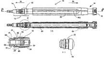
- FIG. 1Ais a side view of the instrument holder of the invention.
- FIG. 1Bis a side, cross-sectional view of the instrument holder of the invention.
- FIG. 1Cis a detail cross-sectional view of the remote release mechanism of the invention.
- FIG. 1Dis a detail view of the remote release mechanism of the invention.
- FIG. 1Eis a detail view of an alternate embodiment of the remote release mechanism of the invention.
- FIG. 2is a perspective view of an instrument for use with the invention.
- FIG. 3is an exploded view of a central drive shaft and locking component of the invention.
- FIG. 4Ais a side view of the head of the invention.
- FIG. 4Bis a cross sectional side view of the head of the invention
- FIG. 4Cis a front view of the head of the invention.
- FIG. 4Dis a perspective view of the head of the invention.
- FIG. 5is a perspective view of a kit of the invention.
- FIG. 6Ais a side, cross-sectional view of an alternate embodiment of the invention.
- FIG. 6Bis a detail view of portion 6 B, the remote locking mechanism of the invention, shown in FIG. 6A .
- the instrument holder 10 for surgical usehas a remote locking mechanism 12 , is elongated having a proximal end 14 and a distal end 16 at opposite ends thereof.
- the holder 10has an elongated shank 20 , a ring 22 , and a locking component 28 .
- the elongated shank 20is equipped, at the distal end, with a head 26 adapted to receive an instrument 24 (shown in FIG. 2 ) and is configured essentially identically to the head described in U.S. Pat. No. 5,658,290, the content of which is incorporated by reference.
- the locking component 28is substantially cylindrical, elongated and is biased in a first direction 30 toward the head 26 by a helical spring 32 .
- the locking component 28includes structures 34 (shown in FIG. 2 ) capable of locking the instrument 24 onto the distal end 16 .
- the ring 22is biased by the spring 32 in a second direction 36 against the locking component 28 towards the proximal end 14 and is constrained to slide longitudinally on the shank 20 , at the proximal end.
- the ring 22is affixed to the shank 20 by a connection device 29 .
- the remote locking mechanism 12permits constrained connection to the shank 20 via the connection device 29 which is engaged by rotation of the ring 22 . Disengagement of the ring from the shank allows the locking component 28 , the spring 32 and the ring 22 to slide freely off the shank in order to permit cleaning of the instrument holder.
- the remote locking mechanism 12preferably includes a bayonet connection device 29 in which the ring 22 is equipped with a bayonet pin 42 placed so as to enter into a bayonet slot 44 and settle into a bayonet recess 46 .
- Two recesses 46are preferably provided, diametrically opposed on opposite sides of the shank 20 , to facilitate assembly.
- the locking structures 34 of the locking component 28are located on the distal end 16 and consist of pins 34 which mount in a face plate 50 which is fixedly attached to a central tubular component 52 of the locking component.
- the locking component 28On a proximal end 14 , the locking component 28 has a raised structure 54 of the form of a frustocone, in order to permit easy gripping by a user, enabling him to push the component back against the force of the spring 32 , to remotely release the instrument 24 .
- an elongated grip 56is slidingly disposed over the locking component 28 for gripping the holder 10 , in a manner that permits sliding of the grip off of the locking component for ease of cleaning and component sterilization.
- a longitudinal slit 56 ais provided in the grip 56 which allows the grip to elastically deform and expand so as to slide over the raised structure 54 when disassembling the holder 10 for cleaning, and is sized so that when compressed such that adjacent surfaces 56 b of the slit 56 a touch before the inner diameter of the grip bears on the tube.
- the inner surface of the grip 56includes two diameters, one larger proximal diameter, of a size enabling the grip 56 to slide over the raised structure 54 without disturbing it and the other distal diameter of a size that retains the grip on the locking component 28 , being removable therefrom with only a slight elastic deformation. This better enables the operator to control the instrument holder 10 without inadvertently activating the remote locking mechanism 12 .
- the shank 20has an elongated cavity 60 extending through the holder 10 from the distal end 16 to the proximal end 14 , to permit evacuation of debris.
- the holder 10typically holds a cutter 24 which, when cutting, generates cutting debris (not shown).
- the head 26bas a central recess 60 b which defines a crown 66 around this recess.
- This crown 66has four bayonet catches 70 diametrically opposite in pairs.
- the instrument 24is fixed and locked in the catches 70 by the annular locking component 28 .
- the pins 34are parallel to each other, are aligned parallel to the axis 72 of the shaft 20 and pass through the head 26 in order to close the bayonet catches 70 around elements 74 of the instrument 24 , as is described in '290 patent.
- the locking component 28slides on the shank 20 . Also arranged around this shank 20 , at the proximal end 14 , remote from the head 26 , is the spring 32 which engages the raised structure 54 of the locking component 28 and bears against this locking component. Starting from the disassembled position shown in FIG. 2 , and in order to assemble the instrument holder 10 , the locking component 28 is brought under the head 26 , engaging its locking fingers 34 through holes 26 a in the head. Then, the spring 32 is slid over the shank 20 .
- the rug 22also slides on the shank 20 , and is equipped internally with radial studs 42 that are captured in bayonet slots 44 , thus permitting the ring to move axially along the shank 20 , and eventually into the bayonet recess 46 , when the ring is turned in a manner directed in FIG. 1D .
- the spring 32is pushed against the locking component 28 and compressed while, at the same time, the ring 22 is turned in a counterclockwise direction until its stud 42 engages in the bayonet catch 46 or respectively in one of the bayonet catches, in which the stud is biased by the spring 32 .
- the ring 22captures the functional components of the assembly together.
- the assembly of the instrument holder 10is completed by the grip 56 , made of a flexible plastic material and having a longitudinal slit 56 a along its side, so as to permit the grip to bias open and slide past the raised structure 54 onto the shank 20 .
- the grip 56may be placed over the locking component 28 as a first step in the assembly process as well.
- the instrument holder 10is then ready for use.
- the raised structure 54provides a grip for the thumb and index finger for pulling the locking component 28 back counter to the action of the spring 32 in order to release any instrument 24 that might be fixed on the head 26 .
- the actuation mechanism 12is remote from the head 26 which holds the instrument 24 . This is accomplished essentially by increasing the length of the locking component 28 in order to move the locking mechanism 12 back away from the attachment head 26 , and then placing the grip 56 over the elongated portion of the locking component 28 .
- the diameter of the shank 20is increased and constructed as a tube in order for its diameter to more closely correspond to the diameter of the grip 56 .
- the components 22 , 28 , and 32can be completely removed from the shank 20 .
- kit 80 of the inventionincluding the instrument holder 10 and an assortment of instruments 24 conveniently organized in a case 82 .
- the grip 56 ′is rigidly affixed to the locking component 28 ′ and may include a raised portion 54 ′ at the proximal end 14 , which aids a user in gripping the locking component to urge the component back against the force of the spring 32 .
- the grip 56may be insert-molded onto the locking component 28 .
- the raised portion 54 ′is preferably frustoconical.
- the grip 56 ′may be threaded onto the locking component 28 and locked in place, in any known fashion.
- an instrument holder 10is provided that is simple to disassemble for cleaning and then reassemble without special tools, quickly, which represents a time savings.
- an instrument holder 10is provided that a surgeon can operate remotely, installing or removing a reamer or other tool in situ, while the tool is inside a cavity or incision in the patient.
- the ability to quickly disassemble the instrument holder 10makes it possible to ensure that a complete kit of instruments is not rendered unusable because a single component becomes inoperative.
Landscapes
- Health & Medical Sciences (AREA)
- Surgery (AREA)
- Life Sciences & Earth Sciences (AREA)
- Biomedical Technology (AREA)
- Medical Informatics (AREA)
- Orthopedic Medicine & Surgery (AREA)
- Oral & Maxillofacial Surgery (AREA)
- Engineering & Computer Science (AREA)
- Dentistry (AREA)
- Heart & Thoracic Surgery (AREA)
- Nuclear Medicine, Radiotherapy & Molecular Imaging (AREA)
- Molecular Biology (AREA)
- Animal Behavior & Ethology (AREA)
- General Health & Medical Sciences (AREA)
- Public Health (AREA)
- Veterinary Medicine (AREA)
- Surgical Instruments (AREA)
Abstract
Description
Claims (15)
Priority Applications (1)
| Application Number | Priority Date | Filing Date | Title |
|---|---|---|---|
| US11/006,485US7326198B2 (en) | 2000-06-24 | 2004-12-07 | Remote release instrument holder for surgical use |
Applications Claiming Priority (5)
| Application Number | Priority Date | Filing Date | Title |
|---|---|---|---|
| US09/602,341US6264647B1 (en) | 2000-03-02 | 2000-06-24 | Instrument holder for surgical instrument |
| US09/902,369US6540739B2 (en) | 2000-03-02 | 2001-07-09 | Surgical instrumentation system |
| US10/391,464US7056317B2 (en) | 2000-03-02 | 2003-03-18 | Instrument holder for surgical instrument |
| US52774803P | 2003-12-09 | 2003-12-09 | |
| US11/006,485US7326198B2 (en) | 2000-06-24 | 2004-12-07 | Remote release instrument holder for surgical use |
Related Parent Applications (1)
| Application Number | Title | Priority Date | Filing Date |
|---|---|---|---|
| US10/391,464Continuation-In-PartUS7056317B2 (en) | 2000-03-02 | 2003-03-18 | Instrument holder for surgical instrument |
Publications (2)
| Publication Number | Publication Date |
|---|---|
| US20050124981A1 US20050124981A1 (en) | 2005-06-09 |
| US7326198B2true US7326198B2 (en) | 2008-02-05 |
Family
ID=34079507
Family Applications (1)
| Application Number | Title | Priority Date | Filing Date |
|---|---|---|---|
| US11/006,485Expired - LifetimeUS7326198B2 (en) | 2000-06-24 | 2004-12-07 | Remote release instrument holder for surgical use |
Country Status (4)
| Country | Link |
|---|---|
| US (1) | US7326198B2 (en) |
| JP (1) | JP2005169121A (en) |
| CH (1) | CH698891B1 (en) |
| GB (1) | GB2408939A (en) |
Cited By (15)
| Publication number | Priority date | Publication date | Assignee | Title |
|---|---|---|---|---|
| US20070083208A1 (en)* | 2000-06-24 | 2007-04-12 | Yves Desarzens | Precision spindle instrument holder for surgical instrument |
| US20070142840A1 (en)* | 2003-03-13 | 2007-06-21 | Goodwin Peter J | Assembly for use in orthopaedic surgery |
| US20080177265A1 (en)* | 2006-12-21 | 2008-07-24 | Andre Lechot | Surgical tool holder and surgical tool |
| US20090082772A1 (en)* | 2007-09-24 | 2009-03-26 | Julian Ferreira | Adapter driver for orthopaedic reamer |
| US20090082771A1 (en)* | 2007-09-20 | 2009-03-26 | Stuart Weekes | Dual reamer driver |
| US20090078096A1 (en)* | 2007-09-25 | 2009-03-26 | Clive Ryall | Adapter for a surgical reamer driver |
| US20120165828A1 (en)* | 2010-12-22 | 2012-06-28 | Intuitive Surgical Operations, Inc. | Alternate instrument removal |
| US8475460B1 (en) | 2010-02-23 | 2013-07-02 | Greatbatch Medical S.A. | Angled reamer spindle for minimally invasive hip replacement surgery |
| US8834471B2 (en) | 2010-02-23 | 2014-09-16 | Greatbatch Medical S.A. | Angled reamer spindle for minimally invasive hip replacement surgery |
| USD780548S1 (en) | 2015-07-22 | 2017-03-07 | Ac (Macao Commercial Offshore) Limited | Power tool |
| USD806493S1 (en) | 2015-07-22 | 2018-01-02 | Tti (Macao Commercial Offshore) Limited | Tool adapter |
| US10441326B2 (en) | 2016-12-23 | 2019-10-15 | Medos International Sérl | Driver instruments and related methods |
| US10687852B2 (en) | 2015-09-14 | 2020-06-23 | Symmetry Medical Manufacturing, Inc. | Separable instrument driver handle |
| US11389212B2 (en) | 2017-02-01 | 2022-07-19 | Medos International Sarl | Multi-function driver instruments and related methods |
| US11457967B2 (en) | 2015-04-13 | 2022-10-04 | Medos International Sarl | Driver instruments and related methods |
Families Citing this family (12)
| Publication number | Priority date | Publication date | Assignee | Title |
|---|---|---|---|---|
| US7955323B2 (en)* | 2000-06-24 | 2011-06-07 | Greatbatch Medical S.A. | Instrument holder and method for a surgical instrument having a park position |
| US7513899B2 (en)* | 2006-01-27 | 2009-04-07 | Howmedica Osteonics Corp. | Acetabular reamer connection mechanism |
| US8065938B1 (en)* | 2006-04-10 | 2011-11-29 | Kravitch Nick C | Interchangable extension tool for performing operations in limited space work areas |
| WO2008002485A2 (en)* | 2006-06-23 | 2008-01-03 | Alza Corporation | Increased amorphous stability of poorly water soluble drugs by nanosizing |
| EP1905362A1 (en)* | 2006-09-29 | 2008-04-02 | Precimed S.A. | Precision assembleable surgical tool handle with limited-play interconnect mechanism |
| GB2446514B (en)* | 2007-02-08 | 2011-06-08 | Precimed Sa | Holder for a surgical reamer and single use,flat reamer |
| US8915675B1 (en)* | 2009-11-23 | 2014-12-23 | Longshot Integrity Services, LLC | Access and connection for a buried pipeline |
| US10568649B2 (en) | 2014-05-06 | 2020-02-25 | Howmedica Osteonics Corp. | Acetabular reamer |
| US10595864B2 (en)* | 2015-11-24 | 2020-03-24 | Covidien Lp | Adapter assembly for interconnecting electromechanical surgical devices and surgical loading units, and surgical systems thereof |
| GB201711177D0 (en)* | 2017-07-12 | 2017-08-23 | Depuy Ireland Ultd Co | Surgical tool release mechanism |
| WO2019092615A1 (en)* | 2017-11-07 | 2019-05-16 | Incipio Devices Sa | Offset reamer driver with remote release mechanism |
| CN114894595B (en)* | 2022-05-26 | 2024-12-06 | 北京纳通医用机器人科技有限公司 | Thermal desorption components and lung cancer detectors |
Citations (7)
| Publication number | Priority date | Publication date | Assignee | Title |
|---|---|---|---|---|
| US5236433A (en) | 1991-05-08 | 1993-08-17 | Othy, Inc. | Tool driver |
| US5658290A (en) | 1994-09-28 | 1997-08-19 | Precifar S.A. | Assembly comprising reamer spindle and reamer for surgery |
| US5817096A (en)* | 1996-11-25 | 1998-10-06 | Othy, Inc. | Tool driver |
| US6102915A (en)* | 1996-02-13 | 2000-08-15 | Advanced Technical Fabrication | Hip prosthesis positioning instrument |
| US6258107B1 (en)* | 1998-08-17 | 2001-07-10 | DEUTSCHES ZENTRUM FüR LUFT-UND RAUMFAHRT E.V. | Apparatus for connecting a variety of surgical instruments to an operating control device |
| US6264647B1 (en) | 2000-03-02 | 2001-07-24 | Precifar S.A. | Instrument holder for surgical instrument |
| US6854742B2 (en)* | 1999-07-09 | 2005-02-15 | Symmetry Medical, Inc. | Tool driver |
Family Cites Families (2)
| Publication number | Priority date | Publication date | Assignee | Title |
|---|---|---|---|---|
| CH693923A5 (en)* | 1999-12-22 | 2004-04-30 | Precimed Sa | Strawberry and strawberry-door. |
| US7115119B2 (en)* | 2000-06-24 | 2006-10-03 | Precimed S.A. | Dual reamer holder for surgical use |
- 2004
- 2004-12-07USUS11/006,485patent/US7326198B2/ennot_activeExpired - Lifetime
- 2004-12-08CHCH02036/04Apatent/CH698891B1/ennot_activeIP Right Cessation
- 2004-12-08GBGB0426893Apatent/GB2408939A/ennot_activeWithdrawn
- 2004-12-09JPJP2004356557Apatent/JP2005169121A/ennot_activeWithdrawn
Patent Citations (7)
| Publication number | Priority date | Publication date | Assignee | Title |
|---|---|---|---|---|
| US5236433A (en) | 1991-05-08 | 1993-08-17 | Othy, Inc. | Tool driver |
| US5658290A (en) | 1994-09-28 | 1997-08-19 | Precifar S.A. | Assembly comprising reamer spindle and reamer for surgery |
| US6102915A (en)* | 1996-02-13 | 2000-08-15 | Advanced Technical Fabrication | Hip prosthesis positioning instrument |
| US5817096A (en)* | 1996-11-25 | 1998-10-06 | Othy, Inc. | Tool driver |
| US6258107B1 (en)* | 1998-08-17 | 2001-07-10 | DEUTSCHES ZENTRUM FüR LUFT-UND RAUMFAHRT E.V. | Apparatus for connecting a variety of surgical instruments to an operating control device |
| US6854742B2 (en)* | 1999-07-09 | 2005-02-15 | Symmetry Medical, Inc. | Tool driver |
| US6264647B1 (en) | 2000-03-02 | 2001-07-24 | Precifar S.A. | Instrument holder for surgical instrument |
Cited By (27)
| Publication number | Priority date | Publication date | Assignee | Title |
|---|---|---|---|---|
| US20070083208A1 (en)* | 2000-06-24 | 2007-04-12 | Yves Desarzens | Precision spindle instrument holder for surgical instrument |
| US7955320B2 (en)* | 2000-06-24 | 2011-06-07 | Greatbatch Medical S.A. | Precision spindle instrument holder for surgical instrument |
| US20070142840A1 (en)* | 2003-03-13 | 2007-06-21 | Goodwin Peter J | Assembly for use in orthopaedic surgery |
| US20080177265A1 (en)* | 2006-12-21 | 2008-07-24 | Andre Lechot | Surgical tool holder and surgical tool |
| US7988692B2 (en)* | 2006-12-21 | 2011-08-02 | Greatbatch Medical S.A. | Surgical tool holder and surgical tool |
| US9198672B2 (en) | 2007-09-20 | 2015-12-01 | Symmetry Medical Manufacturing, Inc. | Dual reamer driver |
| US20090082771A1 (en)* | 2007-09-20 | 2009-03-26 | Stuart Weekes | Dual reamer driver |
| US8398642B2 (en) | 2007-09-20 | 2013-03-19 | Symmetry Medical, Inc. | Dual reamer driver |
| US20090082772A1 (en)* | 2007-09-24 | 2009-03-26 | Julian Ferreira | Adapter driver for orthopaedic reamer |
| US8323284B2 (en) | 2007-09-24 | 2012-12-04 | Symmetry Medical Manufacturing, Inc. | Adapter driver for orthopaedic reamer |
| US20090078096A1 (en)* | 2007-09-25 | 2009-03-26 | Clive Ryall | Adapter for a surgical reamer driver |
| US8439920B2 (en) | 2007-09-25 | 2013-05-14 | Symmetry Medical Manufacturing, Inc. | Adapter for a surgical reamer driver |
| US9173663B2 (en) | 2007-09-25 | 2015-11-03 | Symmetry Medical Manufacturing, Inc. | Adapter for a surgical reamer driver |
| US8475460B1 (en) | 2010-02-23 | 2013-07-02 | Greatbatch Medical S.A. | Angled reamer spindle for minimally invasive hip replacement surgery |
| US8480674B1 (en) | 2010-02-23 | 2013-07-09 | Greatbatch Medical S.A. | Angled reamer spindle for minimally invasive hip replacement surgery |
| US8834471B2 (en) | 2010-02-23 | 2014-09-16 | Greatbatch Medical S.A. | Angled reamer spindle for minimally invasive hip replacement surgery |
| US11357592B2 (en) | 2010-12-22 | 2022-06-14 | Intuitive Surgical Operations, Inc. | Alternate instrument removal |
| US20120165828A1 (en)* | 2010-12-22 | 2012-06-28 | Intuitive Surgical Operations, Inc. | Alternate instrument removal |
| US9241766B2 (en)* | 2010-12-22 | 2016-01-26 | Intuitive Surgical Operations, Inc. | Alternate instrument removal |
| US10441376B2 (en) | 2010-12-22 | 2019-10-15 | Intuitive Surgical Operations, Inc. | Alternate instrument removal |
| US11457967B2 (en) | 2015-04-13 | 2022-10-04 | Medos International Sarl | Driver instruments and related methods |
| USD780548S1 (en) | 2015-07-22 | 2017-03-07 | Ac (Macao Commercial Offshore) Limited | Power tool |
| USD806493S1 (en) | 2015-07-22 | 2018-01-02 | Tti (Macao Commercial Offshore) Limited | Tool adapter |
| US10687852B2 (en) | 2015-09-14 | 2020-06-23 | Symmetry Medical Manufacturing, Inc. | Separable instrument driver handle |
| US10441326B2 (en) | 2016-12-23 | 2019-10-15 | Medos International Sérl | Driver instruments and related methods |
| US11337736B2 (en) | 2016-12-23 | 2022-05-24 | Medos International Sarl | Driver instruments and related methods |
| US11389212B2 (en) | 2017-02-01 | 2022-07-19 | Medos International Sarl | Multi-function driver instruments and related methods |
Also Published As
| Publication number | Publication date |
|---|---|
| US20050124981A1 (en) | 2005-06-09 |
| CH698891B1 (en) | 2009-11-30 |
| GB2408939A (en) | 2005-06-15 |
| JP2005169121A (en) | 2005-06-30 |
| GB0426893D0 (en) | 2005-01-12 |
Similar Documents
| Publication | Publication Date | Title |
|---|---|---|
| US7326198B2 (en) | Remote release instrument holder for surgical use | |
| US7682363B2 (en) | Inserter for minimally invasive joint surgery | |
| US7857816B2 (en) | Inserter for minimally invasive joint surgery having interchangeable thread | |
| US8277457B1 (en) | Orthopaedic inserter using a collet mechanism | |
| US6007560A (en) | Biopsy forceps having detachable handle and distal jaws | |
| US7056317B2 (en) | Instrument holder for surgical instrument | |
| US5810879A (en) | Laparoscopic instrument | |
| US8052691B2 (en) | Spring loaded fixation element insertion device | |
| EP1691733B1 (en) | Inserter for minimally invasive joint surgery | |
| US4491132A (en) | Sheath and retractable surgical tool combination | |
| US20080177265A1 (en) | Surgical tool holder and surgical tool | |
| US12329416B2 (en) | Reamer instruments and related methods | |
| JP2020018844A (en) | Rotation knob assemblies and surgical instruments including the same | |
| CN115052536A (en) | Universal drill guide system | |
| JP2015523164A5 (en) | ||
| US7955320B2 (en) | Precision spindle instrument holder for surgical instrument | |
| CA2448676C (en) | Insertion device for bone fixation elements | |
| WO2005044114A1 (en) | Precision spindle instrument holder for surgical instrument |
Legal Events
| Date | Code | Title | Description |
|---|---|---|---|
| FEPP | Fee payment procedure | Free format text:PAYOR NUMBER ASSIGNED (ORIGINAL EVENT CODE: ASPN); ENTITY STATUS OF PATENT OWNER: LARGE ENTITY | |
| FEPP | Fee payment procedure | Free format text:PAT HOLDER NO LONGER CLAIMS SMALL ENTITY STATUS, ENTITY STATUS SET TO UNDISCOUNTED (ORIGINAL EVENT CODE: STOL); ENTITY STATUS OF PATENT OWNER: LARGE ENTITY | |
| STCF | Information on status: patent grant | Free format text:PATENTED CASE | |
| AS | Assignment | Owner name:PRECIMED S.A., SWITZERLAND Free format text:ASSIGNMENT OF ASSIGNORS INTEREST;ASSIGNORS:DESARZENS, YVES;FEHLBAUM, PHILIPPE;LECHOT, ANDRE;REEL/FRAME:020679/0972;SIGNING DATES FROM 20080314 TO 20080319 | |
| CC | Certificate of correction | ||
| AS | Assignment | Owner name:GREATBATCH MEDICAL S.A., SWITZERLAND Free format text:CHANGE OF NAME;ASSIGNOR:PRECIMED S.A.;REEL/FRAME:023032/0198 Effective date:20090730 Owner name:GREATBATCH MEDICAL S.A.,SWITZERLAND Free format text:CHANGE OF NAME;ASSIGNOR:PRECIMED S.A.;REEL/FRAME:023032/0198 Effective date:20090730 | |
| FPAY | Fee payment | Year of fee payment:4 | |
| CC | Certificate of correction | ||
| FPAY | Fee payment | Year of fee payment:8 | |
| AS | Assignment | Owner name:ROYAL BANK OF CANADA, AS COLLATERAL AGENT, CANADA Free format text:SECURITY INTEREST;ASSIGNOR:BANDERA ACQUISITION, LLC;REEL/FRAME:046472/0545 Effective date:20180702 Owner name:ROYAL BANK OF CANADA, AS COLLATERAL AGENT, CANADA Free format text:SECURITY INTEREST;ASSIGNOR:BANDERA ACQUISITION, LLC;REEL/FRAME:046472/0475 Effective date:20180702 | |
| AS | Assignment | Owner name:BANDERA ACQUISITION, LLC, MASSACHUSETTS Free format text:ASSIGNMENT OF ASSIGNORS INTEREST;ASSIGNOR:GREATBATCH MEDICAL SA;REEL/FRAME:047154/0186 Effective date:20180702 | |
| AS | Assignment | Owner name:VIANT AS&O HOLDINGS, LLC, ARIZONA Free format text:CHANGE OF NAME;ASSIGNOR:BANDERA ACQUISITION, LLC;REEL/FRAME:047221/0275 Effective date:20180824 | |
| MAFP | Maintenance fee payment | Free format text:PAYMENT OF MAINTENANCE FEE, 12TH YEAR, LARGE ENTITY (ORIGINAL EVENT CODE: M1553); ENTITY STATUS OF PATENT OWNER: LARGE ENTITY Year of fee payment:12 | |
| AS | Assignment | Owner name:VIANT AS&O HOLDINGS, LLC, MASSACHUSETTS Free format text:RELEASE BY SECURED PARTY;ASSIGNOR:ROYAL BANK OF CANADA;REEL/FRAME:069276/0081 Effective date:20241029 | |
| AS | Assignment | Owner name:VIANT AS&O HOLDINGS, LLC, MASSACHUSETTS Free format text:RELEASE BY SECURED PARTY;ASSIGNOR:ROYAL BANK OF CANADA;REEL/FRAME:069286/0564 Effective date:20241029 |