US7325843B2 - Latch mechanism - Google Patents
Latch mechanismDownload PDFInfo
- Publication number
- US7325843B2 US7325843B2US10/917,251US91725104AUS7325843B2US 7325843 B2US7325843 B2US 7325843B2US 91725104 AUS91725104 AUS 91725104AUS 7325843 B2US7325843 B2US 7325843B2
- Authority
- US
- United States
- Prior art keywords
- pawl
- latch
- release lever
- latch mechanism
- power
- Prior art date
- Legal status (The legal status is an assumption and is not a legal conclusion. Google has not performed a legal analysis and makes no representation as to the accuracy of the status listed.)
- Expired - Fee Related, expires
Links
- 230000005540biological transmissionEffects0.000claimsabstract5
Images


Classifications
- E—FIXED CONSTRUCTIONS
- E05—LOCKS; KEYS; WINDOW OR DOOR FITTINGS; SAFES
- E05B—LOCKS; ACCESSORIES THEREFOR; HANDCUFFS
- E05B81/00—Power-actuated vehicle locks
- E05B81/12—Power-actuated vehicle locks characterised by the function or purpose of the powered actuators
- E05B81/14—Power-actuated vehicle locks characterised by the function or purpose of the powered actuators operating on bolt detents, e.g. for unlatching the bolt
- E—FIXED CONSTRUCTIONS
- E05—LOCKS; KEYS; WINDOW OR DOOR FITTINGS; SAFES
- E05B—LOCKS; ACCESSORIES THEREFOR; HANDCUFFS
- E05B85/00—Details of vehicle locks not provided for in groups E05B77/00 - E05B83/00
- E05B85/20—Bolts or detents
- E05B85/24—Bolts rotating about an axis
- E05B85/26—Cooperation between bolts and detents
- E—FIXED CONSTRUCTIONS
- E05—LOCKS; KEYS; WINDOW OR DOOR FITTINGS; SAFES
- E05B—LOCKS; ACCESSORIES THEREFOR; HANDCUFFS
- E05B77/00—Vehicle locks characterised by special functions or purposes
- E05B77/22—Functions related to actuation of locks from the passenger compartment of the vehicle
- E05B77/24—Functions related to actuation of locks from the passenger compartment of the vehicle preventing use of an inner door handle, sill button, lock knob or the like
- E05B77/28—Functions related to actuation of locks from the passenger compartment of the vehicle preventing use of an inner door handle, sill button, lock knob or the like for anti-theft purposes, e.g. double-locking or super-locking
- E—FIXED CONSTRUCTIONS
- E05—LOCKS; KEYS; WINDOW OR DOOR FITTINGS; SAFES
- E05B—LOCKS; ACCESSORIES THEREFOR; HANDCUFFS
- E05B81/00—Power-actuated vehicle locks
- E05B81/02—Power-actuated vehicle locks characterised by the type of actuators used
- E05B81/04—Electrical
- E05B81/06—Electrical using rotary motors
- E—FIXED CONSTRUCTIONS
- E05—LOCKS; KEYS; WINDOW OR DOOR FITTINGS; SAFES
- E05B—LOCKS; ACCESSORIES THEREFOR; HANDCUFFS
- E05B81/00—Power-actuated vehicle locks
- E05B81/54—Electrical circuits
- E05B81/90—Manual override in case of power failure
- Y—GENERAL TAGGING OF NEW TECHNOLOGICAL DEVELOPMENTS; GENERAL TAGGING OF CROSS-SECTIONAL TECHNOLOGIES SPANNING OVER SEVERAL SECTIONS OF THE IPC; TECHNICAL SUBJECTS COVERED BY FORMER USPC CROSS-REFERENCE ART COLLECTIONS [XRACs] AND DIGESTS
- Y10—TECHNICAL SUBJECTS COVERED BY FORMER USPC
- Y10S—TECHNICAL SUBJECTS COVERED BY FORMER USPC CROSS-REFERENCE ART COLLECTIONS [XRACs] AND DIGESTS
- Y10S292/00—Closure fasteners
- Y10S292/23—Vehicle door latches
- Y—GENERAL TAGGING OF NEW TECHNOLOGICAL DEVELOPMENTS; GENERAL TAGGING OF CROSS-SECTIONAL TECHNOLOGIES SPANNING OVER SEVERAL SECTIONS OF THE IPC; TECHNICAL SUBJECTS COVERED BY FORMER USPC CROSS-REFERENCE ART COLLECTIONS [XRACs] AND DIGESTS
- Y10—TECHNICAL SUBJECTS COVERED BY FORMER USPC
- Y10T—TECHNICAL SUBJECTS COVERED BY FORMER US CLASSIFICATION
- Y10T292/00—Closure fasteners
- Y10T292/08—Bolts
- Y10T292/1043—Swinging
- Y10T292/1044—Multiple head
- Y10T292/1045—Operating means
- Y10T292/1047—Closure
- Y—GENERAL TAGGING OF NEW TECHNOLOGICAL DEVELOPMENTS; GENERAL TAGGING OF CROSS-SECTIONAL TECHNOLOGIES SPANNING OVER SEVERAL SECTIONS OF THE IPC; TECHNICAL SUBJECTS COVERED BY FORMER USPC CROSS-REFERENCE ART COLLECTIONS [XRACs] AND DIGESTS
- Y10—TECHNICAL SUBJECTS COVERED BY FORMER USPC
- Y10T—TECHNICAL SUBJECTS COVERED BY FORMER US CLASSIFICATION
- Y10T292/00—Closure fasteners
- Y10T292/08—Bolts
- Y10T292/1043—Swinging
- Y10T292/1075—Operating means
- Y10T292/1082—Motor
Definitions
- This inventionrelates to a latch mechanism for a vehicle door, particularly, but not exclusively, for light passenger and goods vehicles.
- Powered locking/unlocking and powered latching/unlatching of doorsis becoming more favored, both as part of a central locking system and to enable more effective weathersealing of doors and greater freedom in styling and design.
- Power actuated unlatching of doorsprovides advantages. For one, many of the mechanical linkages and components needed for conventional manual inside and outside door handles can be dispensed with. Additionally, unitary lock and latch modules of standard form can be provided which can be quickly installed in doors of a wide range of vehicle models and types without special adaptation.
- the present inventionseeks to overcome, or at least mitigate, the problems of the prior art, in particular to provide a more compact and cost effective latch mechanism.
- a latchincludes a pivotal latch claw having a mouth that co-acts with a striker operatively mounted to an associated door post.
- a pawl tooth of a latching pawlself-engages with a first safety abutment of the latch claw to retain the latch claw releasably at a first safety position at which a door is near closed.
- the pawl tooth of the latching pawlself-engages with a second safety abutment of the latch claw to retain the latch claw at an inner position at which the door is fully shut.
- a pawl lifterengages the latch pawl to disengage the latch pawl from the latch claw to open the door.
- a manual release leveris operatively connected to a door handle by a mechanical linkage.
- a lug of the manual release leverprovides a lost-motion connection between the manual release lever and the pawl lifter such that rotation of the manual release lever rotates the pawl lifter.
- the manual release leverincludes a lug that is received within a window of a clutch lever and provides a lost motion connection between the manual release lever and the clutch lever.
- the latchalso includes a power release lever.
- An electric motordrives the power release lever from a rest position to an actuated position in response to a signal from a controller.
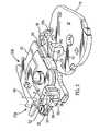
- FIG. 1is a perspective view of a vehicle door latch in a partially assembled state
- FIG. 2is a perspective view of parts of the vehicle door latch according to one embodiment of the present invention in a rest position with some parts not relevant to the invention removed for clarity;
- FIG. 3is a perspective view of a pawl lifter of the vehicle door latch of FIG. 2 ;
- FIG. 4is a perspective view of a manual release lever of the vehicle door latch of FIG. 2 ;
- FIG. 5is a plan view of the latch of FIG. 2 in a rest position
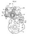
- FIG. 6is a plan view of the vehicle door latch of FIG. 2 in a clutch engaged position.
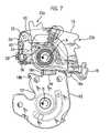
- FIG. 7is a plan view of the vehicle door latch of FIG. 2 in a released position.
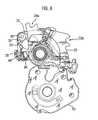
- FIG. 8is a plan view of the vehicle door latch of FIG. 2 in a clutch position.
- FIG. 9is a plan view of a vehicle door latch according to a second embodiment of the present invention in a rest position
- FIG. 10is a plan view of a the vehicle door latch according to the second embodiment of the present invention in clutch engaged position.
- FIG. 11is a plan view of the vehicle door latch according to the second embodiment of the present invention in a release position.
- FIG. 12is a plan view of the vehicle door latch according to the second embodiment of the present invention in a clutch disengaged position.
- FIG. 1illustrates a latch 8 , which will be operatively secured in a door (not shown) in a known manner.
- the latch 8includes a conventional latch bolt in the form of a rotating latch claw 10 having a mouth 12 for co-acting with a striker (not shown) operatively mounted to an associated door post.
- the latch claw 10is pivotally mounted to a retention plate 9 of the latch 8 via a claw pin 11 and is biased by a claw spring (not shown) in a counter-clockwise direction.
- a pawl tooth 16 a of a latching pawl 16self-engages with a first safety abutment 18 a of the latch claw 10 in a known manner to releasably retain the latch claw 10 , and hence the door, at a first safety position at which the door is near closed.
- the pawl tooth 16 a of the latching pawl 16self-engages with a second safety abutment 18 b of the latch claw 10 to retain the latch claw 10 at an inner position at which the door is fully shut.
- the latching pawl 16is pivotally mounted to the retention plate 9 via a pawl pin 17 and further includes a slot 19 for engagement by a pawl lifter 20 (shown in FIGS. 2 and 3 ).
- an unlatching mechanism of a latch mechanism of the latch 8includes the pawl lifter 20 in the form of a lever pivoted co-axially with, and on top of, the latching pawl 16 on the pawl pin 17 .
- the pawl lifter 20includes a lug 21 that engages the slot 19 of the latching pawl 16 .
- the pawl lifter 20causes disengagement of the latching pawl 16 from the latch claw 10 to allow the door to open.
- a clutch member in the form of a clutch lever 30is pivotally mounted to the pawl lifter 20 by a pin 32 that is offset from the pawl pin 17 and resiliently biased in a clockwise direction relative to the pawl lifter 20 by a clutch lever spring 100 .
- the clutch lever 30includes a window 34 and a projection 36 that extends away from the pawl lifter 20 .
- a stop 38 formed from the pawl lifter 20limits clockwise rotation of the clutch lever 30 .
- a manually operable release mechanism of the assemblyincludes a manual release lever 22 , best seen in FIG. 4 , operatively connected to an inside door handle 48 and an outside door handle 50 (shown schematically) via a mechanical linkage including inside and outside release levers (not shown) configured to engage lug formations 23 a and 23 b , respectively, on the manual release lever 22 .
- the manual release lever 22is pivotally mounted on the pawl pin 17 co-axially, but independently of the pawl lifter 20 , overlying the pawl lifter 20 as viewed in FIG. 2 .
- a further lug 24 of the manual release lever 22provides a lost-motion connection between the manual release lever 22 and the pawl lifter 20 such that the pawl lifter 20 is rotated by counter-clockwise rotation of the manual release lever 22 .
- a torsion spring(not visible) biases the manual release lever 22 in a clockwise direction relative to the pawl lifter 20 .
- the manual release lever 22includes a further lug 26 (shown in FIG. 4 ) that is received within the window 34 of the clutch lever 30 and provides a lost motion connection between the manual release lever 22 and the clutch lever 30 .
- the further lug 26In the rest position (shown in FIGS. 2 and 5 ), the further lug 26 substantially holds the clutch lever 30 at its counter-clockwise limit of rotation, overcoming the force of the clutch lever spring and providing a gap between the projection 36 and the stop 38
- a power release member in the form of a power release lever 40(shown in broken lines in FIGS. 2 and 3 and in solid cross-section in FIGS. 5 and 7 ) is fulcrummed on a fixed pivot whose axis is at a right angle relative to the claw pin 11 and the pawl pin 17 .
- FIGS. 2 , 3 and 5show the power release lever 40 in a rest position
- FIG. 7shows the power release lever 40 in an actuated position.
- a power actuator(which includes only actuators whose power source is the vehicle to which the latch is fitted, as opposed to vehicle users or other external power sources), such as an electric motor 44 (illustrated schematically), is capable of driving the power release lever 40 in a direction X from the rest position to the actuated position in response to a signal from a controller 46 .
- the controller 46receives electrical inputs from the inside door handle 48 and the outside door handle 50 and a locking mechanism 52 .
- the controller 46is capable of determining whether to signal the driving of the electric motor 44 on the basis of its inputs and its internal logic in a known way (e.g., if the locking mechanism is superlocked, then the controller will not signal the driving of the motor irrespective of the inputs from either the inside door handle 48 or the outside door handle 50 ).
- the locking mechanismmay also provide a suitable break or block in the mechanical connection between the inside door handle 48 and/or the outside door handle 50 and the power release lever 40 , depending upon the locked state of the latch 8 , as is known in the art.
- the controller 46signals the electric motor 44 to drive and pivot the power release lever 40 in direction X.
- the timing of this actuationis controlled to ensure that the clutch lever 30 has already pivoted clockwise.
- the power release lever 40abuts the projection 36 , forcing the pawl lifter 20 and the latching pawl 16 to rotate counter-clockwise, as indicated by arrow A of FIG. 7 . Consequently, the pawl tooth 16 a disengages from the latch claw 10 .
- the latch claw 10is now free to rotate counter-clockwise, as indicated by arrow B, to release the striker and thereby enable the user to open the door.
- the latch 8may also be manually unlatched as a safety backup system if power unlatching fails.
- the userFor manual unlatching to occur, the user must pull further on the inside door handle 48 or the outside door handle 50 than is required for power unlatching so that the manual release lever 22 is rotated to a point beyond that at which the further lug 24 abuts the pawl lifter 20 so that the pawl tooth 16 a is manually lifted clear of the latch claw 10 .
- the doorcan thus still be opened and closed in the normal way even if power actuation should fail, for example due a flat battery.
- the mechanismis reset when the door is reclosed.
- manual releasemay be achieved by a two-pull process.
- the projection 36 of the clutch lever 30is not in the clockwise position of FIG. 6 .
- the power release lever 40therefore does not contact the projection 36 and moves to the full extent of its travel without rotating the pawl lifter 20 (i.e., it cannot move any further down than the position shown in FIG. 8 to rotate the pawl lifter 20 ). In this condition, power unlatching cannot occur.
- FIGS. 9 to 12illustrate a second embodiment of the present invention. Like parts are, where possible, indicated by the same numerals as for the first embodiment, but with the prefix “1”. Only those differences with respect to the first embodiment are discussed in more detail below.
- the pawl 116 and the claw 110are substantially the same as those of the first embodiment, and the pawl lifter 120 is pivotally mounted co-axially with the pawl 116 .
- a simplified representation of the manual release lever 122is co-axially mounted with the pawl lifter 120 , and a lost motion connection allows limited relative motion between the manual release lever 122 and the pawl lifter 120 .
- An elongate clutch lever 130is positioned on top of (i.e., extending further out of the plane of FIG. 9 than) the pawl lifter 120 and the manual release lever 122 .
- a first projection 132 and a second projection 136are provided proximate to each end of the elongate clutch lever 130 .
- the first projection 132extends into the plane of FIG. 9 and is located in a first slot 125 in the pawl lifter 120 .
- the second projection 136extends both into and out of the plane of FIG. 9 when viewed in FIG. 9 .
- the portion extending into the paperis located in a second slot 127 in the pawl lifter 120 .
- the portion extending out of the plane of FIG. 9may be abutted by the power release lever 140 .
- the first slot 125 and the second slot 127are substantially parallel.
- a cam follower 139extends into the paper between the first projection 132 and the second projection 136 and is arranged to contact a peripheral cam surface of the manual release lever 122 having a relatively small constant radius portion 160 and a relatively large constant radius portion 162 .
- a ramp portion 166is between the relatively small constant radius portion 160 and the relatively large constant radius portion 162 .
- a spring 168 acting between the first projection 132 and the cam follower 139urges the first projection 132 and the second projection 136 towards the right-hand end of the first slot 125 and the second slot 127 and urges the cam follower 139 into contact with the relatively small constant radius portion 160 and the relatively large constant radius portion 162 .
- the elongate clutch lever 130pivots clockwise as indicated by arrow Z 1 to the position shown in FIG. 10 .
- a “high” signalis sent to the controller 46 . Since the locking mechanism 52 indicates that the latch 8 is unlocked, the controller 46 signals the electric motor 44 to drive and pivot the power release lever 140 in direction X1. The timing of this actuation is controlled to ensure that the clutch lever 30 has already pivoted clockwise. As a result, the power release lever 140 abuts the portion of the second projection 136 extending out of the paper, forcing the pawl lifter 120 and the pawl 116 to rotate counter-clockwise as indicated by arrow Al of FIG. 11 . Consequently, the pawl tooth 116 a disengages from the claw 110 , which is now free to rotate counter-clockwise to release the striker and enable the user to open the door.
- the latch mechanism of this embodimentmay also be manually unlatched by pulling further on the inside door handle 48 or the outside door handle 50 as a safety backup system should power unlatching fail.
- the second projection 136 of the clutch lever 30is not in the clockwise position of FIG. 10 because the cam follower remains on the relatively small constant radius portion 160 of the cam surface.
- the power release lever 140therefore does not contact the second projection 136 and moves to the full extent of its travel without causing rotation of the pawl lifter 120 .
- the shifting of the cam follower 139 to the relatively large constant radius portion 162overcomes the resilience of the spring 168 to move the first projection 132 left within the first slot 125 and pivot the elongate clutch lever 130 counter-clockwise about the second projection 136 .
- Rotation of the manual release lever 122 , and hence the pawl lifter 120 and the pawl 116is not blocked and manual release may be achieved.
- Both embodiments of the present inventionprovide a compact and reliable mechanism for ensuring that a power actuator or controller malfunction will not result in release of a latch.
- the pawl lifter and pawlmay be provided as a single component, and any suitable alternative form of mechanism for providing a break in the power unlatching transmission path that is mounted on the pawl lifter may be provided.
- the mechanismdoes not necessarily need to be provided with a back-up manual release, and alternative power actuators such as pneumatic motors or solenoids may used in the place of the electric motor.
Landscapes
- Lock And Its Accessories (AREA)
Abstract
Description
Claims (17)
Applications Claiming Priority (2)
| Application Number | Priority Date | Filing Date | Title |
|---|---|---|---|
| GB0319030.3 | 2003-08-13 | ||
| GB0319030AGB0319030D0 (en) | 2003-08-13 | 2003-08-13 | Latch mechanism |
Publications (2)
| Publication Number | Publication Date |
|---|---|
| US20050035604A1 US20050035604A1 (en) | 2005-02-17 |
| US7325843B2true US7325843B2 (en) | 2008-02-05 |
Family
ID=28052452
Family Applications (1)
| Application Number | Title | Priority Date | Filing Date |
|---|---|---|---|
| US10/917,251Expired - Fee RelatedUS7325843B2 (en) | 2003-08-13 | 2004-08-12 | Latch mechanism |
Country Status (4)
| Country | Link |
|---|---|
| US (1) | US7325843B2 (en) |
| EP (1) | EP1507056A3 (en) |
| CN (1) | CN1580475A (en) |
| GB (1) | GB0319030D0 (en) |
Cited By (23)
| Publication number | Priority date | Publication date | Assignee | Title |
|---|---|---|---|---|
| US20070068317A1 (en)* | 2005-08-12 | 2007-03-29 | Krupin Vladimir G | Ratchet-type parking brake having quiet operation |
| US20080001412A1 (en)* | 2006-06-30 | 2008-01-03 | Mitsui Mining & Smelting Co., Ltd. | Door opening/closing device |
| US20100235058A1 (en)* | 2009-03-12 | 2010-09-16 | Kosta Papanikolaou | Latch mechanism |
| US20100235057A1 (en)* | 2009-03-12 | 2010-09-16 | Kosta Papanikolaou | Universal global latch system |
| US20110204690A1 (en)* | 2008-06-13 | 2011-08-25 | Kiekert Ag | Closing device comprising two pawls and a motor-driven actuating mechanism |
| US8528950B2 (en) | 2010-02-01 | 2013-09-10 | Strattec Security Corporation | Latch mechanism and latching method |
| US20140007404A1 (en)* | 2009-03-12 | 2014-01-09 | Ford Global Technologies, Llc | Universal global latch system |
| US9834964B2 (en) | 2014-05-13 | 2017-12-05 | Ford Global Technologies, Llc | Powered vehicle door latch and exterior handle with sensor |
| US9903142B2 (en) | 2014-05-13 | 2018-02-27 | Ford Global Technologies, Llc | Vehicle door handle and powered latch system |
| US10119308B2 (en) | 2014-05-13 | 2018-11-06 | Ford Global Technologies, Llc | Powered latch system for vehicle doors and control system therefor |
| US10227810B2 (en) | 2016-08-03 | 2019-03-12 | Ford Global Technologies, Llc | Priority driven power side door open/close operations |
| US10273725B2 (en) | 2014-05-13 | 2019-04-30 | Ford Global Technologies, Llc | Customer coaching method for location of E-latch backup handles |
| US10323442B2 (en) | 2014-05-13 | 2019-06-18 | Ford Global Technologies, Llc | Electronic safe door unlatching operations |
| US10329823B2 (en) | 2016-08-24 | 2019-06-25 | Ford Global Technologies, Llc | Anti-pinch control system for powered vehicle doors |
| US10377343B2 (en) | 2015-10-12 | 2019-08-13 | Ford Global Technologies, Llc | Keyless vehicle systems |
| US10422166B2 (en) | 2013-11-21 | 2019-09-24 | Ford Global Technologies, Llc | Piezo based energy harvesting for E-latch systems |
| US10458171B2 (en) | 2016-09-19 | 2019-10-29 | Ford Global Technologies, Llc | Anti-pinch logic for door opening actuator |
| US10494838B2 (en) | 2011-11-02 | 2019-12-03 | Ford Global Technologies, Llc | Electronic interior door release system |
| US10526821B2 (en) | 2014-08-26 | 2020-01-07 | Ford Global Technologies, Llc | Keyless vehicle door latch system with powered backup unlock feature |
| US10550610B2 (en) | 2016-06-22 | 2020-02-04 | Ford Global Technologies, Llc | Inside override emergency handle for door release |
| US10604970B2 (en) | 2017-05-04 | 2020-03-31 | Ford Global Technologies, Llc | Method to detect end-of-life in latches |
| US10697224B2 (en) | 2016-08-04 | 2020-06-30 | Ford Global Technologies, Llc | Powered driven door presenter for vehicle doors |
| US10907386B2 (en) | 2018-06-07 | 2021-02-02 | Ford Global Technologies, Llc | Side door pushbutton releases |
Families Citing this family (12)
| Publication number | Priority date | Publication date | Assignee | Title |
|---|---|---|---|---|
| CN101568695B (en)* | 2006-10-31 | 2013-02-06 | 索斯科公司 | Latch |
| JP4528804B2 (en)* | 2007-06-27 | 2010-08-25 | 三井金属鉱業株式会社 | Door latch device for automobile |
| DE102007041478A1 (en)* | 2007-08-31 | 2009-03-05 | Kiekert Ag | Gesperrebauteil for a motor vehicle lock with a pivot bearing point |
| DE102008057961A1 (en)* | 2008-11-19 | 2010-05-20 | Kiekert Ag | Locking unit with multi-ratchet lock |
| US8123262B2 (en)* | 2008-12-24 | 2012-02-28 | GM Global Technology Operations LLC | Damping assembly for reducing vibrations in a latch for a vehicle door |
| DE102010062000A1 (en)* | 2010-11-25 | 2012-05-31 | Kiekert Ag | Lock module for a motor vehicle |
| KR101382913B1 (en)* | 2012-09-05 | 2014-04-08 | 기아자동차주식회사 | 2 Step link hood latch apparatus for vehicle |
| KR101495643B1 (en)* | 2013-04-04 | 2015-02-25 | 평화정공 주식회사 | Hood latch having dual unlocking function |
| FR3048010B1 (en)* | 2016-02-19 | 2023-03-17 | Inteva Products Llc | Vehicle door lock assembly and system |
| US10822846B2 (en)* | 2017-09-01 | 2020-11-03 | GM Global Technology Operations LLC | Latch mechanism for a vehicle |
| CN111622623B (en)* | 2019-02-28 | 2021-09-21 | 比亚迪股份有限公司 | Door lock device and vehicle with same |
| DE102021100739A1 (en)* | 2021-01-15 | 2022-07-21 | Kiekert Aktiengesellschaft | motor vehicle lock |
Citations (7)
| Publication number | Priority date | Publication date | Assignee | Title |
|---|---|---|---|---|
| US5454608A (en)* | 1993-10-12 | 1995-10-03 | General Motors Corporation | Vehicle door latch |
| US5632515A (en) | 1993-12-13 | 1997-05-27 | Mitsui Kinzoku Kogyo Kabusiki Kaisha | Latch device for use with a vehicle trunk lid |
| EP0828049A2 (en) | 1996-09-07 | 1998-03-11 | VDO Adolf Schindling AG | Locking device, specially for vehicle doors or the like |
| US5803515A (en)* | 1996-09-04 | 1998-09-08 | General Motors Corporation | Vehicle door latch |
| WO2000011290A1 (en) | 1998-08-19 | 2000-03-02 | Meritor Light Vehicle Systems (Uk) Ltd. | Vehicle door latch |
| US6540271B1 (en)* | 1998-07-15 | 2003-04-01 | Meritor Light Vehicle Systems (Uk) Limited | Vehicle door latch |
| US6883839B2 (en)* | 2002-02-12 | 2005-04-26 | Arvinmeritor Light Vehicle Systems - France | Automobile vehicle lock |
- 2003
- 2003-08-13GBGB0319030Apatent/GB0319030D0/ennot_activeCeased
- 2004
- 2004-07-26EPEP20040254449patent/EP1507056A3/ennot_activeWithdrawn
- 2004-08-12USUS10/917,251patent/US7325843B2/ennot_activeExpired - Fee Related
- 2004-08-13CNCNA2004100581862Apatent/CN1580475A/enactivePending
Patent Citations (8)
| Publication number | Priority date | Publication date | Assignee | Title |
|---|---|---|---|---|
| US5454608A (en)* | 1993-10-12 | 1995-10-03 | General Motors Corporation | Vehicle door latch |
| US5632515A (en) | 1993-12-13 | 1997-05-27 | Mitsui Kinzoku Kogyo Kabusiki Kaisha | Latch device for use with a vehicle trunk lid |
| US5803515A (en)* | 1996-09-04 | 1998-09-08 | General Motors Corporation | Vehicle door latch |
| EP0828049A2 (en) | 1996-09-07 | 1998-03-11 | VDO Adolf Schindling AG | Locking device, specially for vehicle doors or the like |
| US6540271B1 (en)* | 1998-07-15 | 2003-04-01 | Meritor Light Vehicle Systems (Uk) Limited | Vehicle door latch |
| WO2000011290A1 (en) | 1998-08-19 | 2000-03-02 | Meritor Light Vehicle Systems (Uk) Ltd. | Vehicle door latch |
| US6601883B1 (en)* | 1998-08-19 | 2003-08-05 | Meritor Light Vehicle Systems (Uk) Limited | Vehicle door latch |
| US6883839B2 (en)* | 2002-02-12 | 2005-04-26 | Arvinmeritor Light Vehicle Systems - France | Automobile vehicle lock |
Non-Patent Citations (2)
| Title |
|---|
| European Search Report dated Feb. 14, 2007. |
| Search Report under Sec. 17, Feb. 10, 2004. |
Cited By (38)
| Publication number | Priority date | Publication date | Assignee | Title |
|---|---|---|---|---|
| US20070068317A1 (en)* | 2005-08-12 | 2007-03-29 | Krupin Vladimir G | Ratchet-type parking brake having quiet operation |
| US20080001412A1 (en)* | 2006-06-30 | 2008-01-03 | Mitsui Mining & Smelting Co., Ltd. | Door opening/closing device |
| US7488014B2 (en)* | 2006-06-30 | 2009-02-10 | Mitsui Mining & Smelting Co., Ltd. | Door opening/closing device |
| US20110204690A1 (en)* | 2008-06-13 | 2011-08-25 | Kiekert Ag | Closing device comprising two pawls and a motor-driven actuating mechanism |
| US8757679B2 (en)* | 2008-06-13 | 2014-06-24 | Kiekert Ag | Closing device comprising two pawls and a motor-driven actuating mechanism |
| US20140007404A1 (en)* | 2009-03-12 | 2014-01-09 | Ford Global Technologies, Llc | Universal global latch system |
| US8573657B2 (en)* | 2009-03-12 | 2013-11-05 | Ford Global Technologies, Llc | Latch mechanism |
| US20100235057A1 (en)* | 2009-03-12 | 2010-09-16 | Kosta Papanikolaou | Universal global latch system |
| US8746755B2 (en)* | 2009-03-12 | 2014-06-10 | Ford Global Technologies, Llc | Universal global latch system |
| US20100235058A1 (en)* | 2009-03-12 | 2010-09-16 | Kosta Papanikolaou | Latch mechanism |
| US9260882B2 (en)* | 2009-03-12 | 2016-02-16 | Ford Global Technologies, Llc | Universal global latch system |
| US10907385B2 (en) | 2009-03-12 | 2021-02-02 | Ford Global Technologies, Llc | Universal global latch system |
| US10563436B2 (en) | 2009-03-12 | 2020-02-18 | Ford Global Technologies, Llc | Universal global latch system |
| US10316553B2 (en) | 2009-03-12 | 2019-06-11 | Ford Global Technologies, Llc | Universal global latch system |
| US8528950B2 (en) | 2010-02-01 | 2013-09-10 | Strattec Security Corporation | Latch mechanism and latching method |
| US10494838B2 (en) | 2011-11-02 | 2019-12-03 | Ford Global Technologies, Llc | Electronic interior door release system |
| US10422166B2 (en) | 2013-11-21 | 2019-09-24 | Ford Global Technologies, Llc | Piezo based energy harvesting for E-latch systems |
| US10301855B2 (en) | 2014-05-13 | 2019-05-28 | Ford Global Technologies, Llc | Electronic control system and sensor for electrically powered vehicle door latches |
| US9834964B2 (en) | 2014-05-13 | 2017-12-05 | Ford Global Technologies, Llc | Powered vehicle door latch and exterior handle with sensor |
| US10267068B2 (en) | 2014-05-13 | 2019-04-23 | Ford Global Technologies, Llc | Electronic vehicle access control system |
| US10323442B2 (en) | 2014-05-13 | 2019-06-18 | Ford Global Technologies, Llc | Electronic safe door unlatching operations |
| US11555336B2 (en) | 2014-05-13 | 2023-01-17 | Ford Global Technologies, Llc | Electronic safe door unlatching operations |
| US11466484B2 (en) | 2014-05-13 | 2022-10-11 | Ford Global Technologies, Llc | Powered latch system for vehicle doors and control system therefor |
| US10273725B2 (en) | 2014-05-13 | 2019-04-30 | Ford Global Technologies, Llc | Customer coaching method for location of E-latch backup handles |
| US9903142B2 (en) | 2014-05-13 | 2018-02-27 | Ford Global Technologies, Llc | Vehicle door handle and powered latch system |
| US10119308B2 (en) | 2014-05-13 | 2018-11-06 | Ford Global Technologies, Llc | Powered latch system for vehicle doors and control system therefor |
| US10526821B2 (en) | 2014-08-26 | 2020-01-07 | Ford Global Technologies, Llc | Keyless vehicle door latch system with powered backup unlock feature |
| US10377343B2 (en) | 2015-10-12 | 2019-08-13 | Ford Global Technologies, Llc | Keyless vehicle systems |
| US10550610B2 (en) | 2016-06-22 | 2020-02-04 | Ford Global Technologies, Llc | Inside override emergency handle for door release |
| US10584526B2 (en) | 2016-08-03 | 2020-03-10 | Ford Global Technologies, Llc | Priority driven power side door open/close operations |
| US10227810B2 (en) | 2016-08-03 | 2019-03-12 | Ford Global Technologies, Llc | Priority driven power side door open/close operations |
| US10697224B2 (en) | 2016-08-04 | 2020-06-30 | Ford Global Technologies, Llc | Powered driven door presenter for vehicle doors |
| US10934760B2 (en) | 2016-08-24 | 2021-03-02 | Ford Global Technologies, Llc | Anti-pinch control system for powered vehicle doors |
| US10329823B2 (en) | 2016-08-24 | 2019-06-25 | Ford Global Technologies, Llc | Anti-pinch control system for powered vehicle doors |
| US10458171B2 (en) | 2016-09-19 | 2019-10-29 | Ford Global Technologies, Llc | Anti-pinch logic for door opening actuator |
| US11180943B2 (en) | 2016-09-19 | 2021-11-23 | Ford Global Technologies, Llc | Anti-pinch logic for door opening actuator |
| US10604970B2 (en) | 2017-05-04 | 2020-03-31 | Ford Global Technologies, Llc | Method to detect end-of-life in latches |
| US10907386B2 (en) | 2018-06-07 | 2021-02-02 | Ford Global Technologies, Llc | Side door pushbutton releases |
Also Published As
| Publication number | Publication date |
|---|---|
| GB0319030D0 (en) | 2003-09-17 |
| EP1507056A3 (en) | 2007-03-28 |
| CN1580475A (en) | 2005-02-16 |
| EP1507056A2 (en) | 2005-02-16 |
| US20050035604A1 (en) | 2005-02-17 |
Similar Documents
| Publication | Publication Date | Title |
|---|---|---|
| US7325843B2 (en) | Latch mechanism | |
| US6601883B1 (en) | Vehicle door latch | |
| US6540271B1 (en) | Vehicle door latch | |
| CN1975084B (en) | Operating device of a door latch in a vehicle | |
| US7399010B2 (en) | Power-actuated motor-vehicle door latch with quick unlock | |
| EP1192328B1 (en) | Vehicle door latch assembly | |
| US7261338B2 (en) | Single actuator power close latch mechanism with failsafe | |
| US6764113B1 (en) | Powered vehicle door latch and actuator therefor | |
| US7070213B2 (en) | Door release and engagement mechanism | |
| US20050200137A1 (en) | Latch apparatus and method | |
| US4998758A (en) | Low effort remote latch actuator | |
| US8632106B2 (en) | Drive unit comprising a blocked functional element for a central locking mechanism | |
| CN113431448A (en) | Locking system for locking a movable panel | |
| US6863318B2 (en) | Latch for a vehicle door | |
| US7048314B2 (en) | Power operable latch that relatches in the event of motor failure | |
| US6082158A (en) | Closing device | |
| US20030218340A1 (en) | Latch arrangement | |
| EP0887500B1 (en) | Vehicle door latch | |
| US8840154B2 (en) | Motor vehicle door lock | |
| EP1212501B1 (en) | A powered vehicle door latch and actuator therefor | |
| US6431619B1 (en) | Door mechanism | |
| US20230313570A1 (en) | Power child lock actuator | |
| KR20080009840A (en) | Door Inside Handle Assembly of Vehicle | |
| KR100415689B1 (en) | Rear door latch structure of vehicle for preventing jam |
Legal Events
| Date | Code | Title | Description |
|---|---|---|---|
| AS | Assignment | Owner name:ARVINMERITOR LIGHT VEHICLE SYSTEMS (UK) LIMITED, U Free format text:ASSIGNMENT OF ASSIGNORS INTEREST;ASSIGNORS:COLEMAN, PETER;KALSI, GURBINDER;REEL/FRAME:015911/0109;SIGNING DATES FROM 20040802 TO 20040831 | |
| AS | Assignment | Owner name:MERITOR TECHNOLOGY, INC., MICHIGAN Free format text:ASSIGNMENT OF ASSIGNORS INTEREST;ASSIGNOR:ARVINMERITOR LIGHT VEHICLE SYSTEMS (UK) LIMITED;REEL/FRAME:019655/0582 Effective date:20060926 | |
| AS | Assignment | Owner name:BODY SYSTEMS USA, LLC, MICHIGAN Free format text:ASSIGNMENT OF ASSIGNORS INTEREST;ASSIGNOR:MERITOR TECHNOLOGY, INC.;REEL/FRAME:025552/0911 Effective date:20101216 | |
| REMI | Maintenance fee reminder mailed | ||
| LAPS | Lapse for failure to pay maintenance fees | ||
| STCH | Information on status: patent discontinuation | Free format text:PATENT EXPIRED DUE TO NONPAYMENT OF MAINTENANCE FEES UNDER 37 CFR 1.362 | |
| FP | Lapsed due to failure to pay maintenance fee | Effective date:20120205 | |
| AS | Assignment | Owner name:INTEVA PRODUCTS, LLC, MICHIGAN Free format text:CHANGE OF NAME;ASSIGNOR:BODY SYSTEMS USA, LLC;REEL/FRAME:033472/0825 Effective date:20110127 | |
| AS | Assignment | Owner name:INTEVA PRODUCTS USA, LLC, MICHIGAN Free format text:CHANGE OF NAME;ASSIGNOR:BODY SYSTEMS USA, LLC;REEL/FRAME:033763/0662 Effective date:20110127 |