US7325162B2 - Configurable multiple channel discrete output module - Google Patents
Configurable multiple channel discrete output moduleDownload PDFInfo
- Publication number
- US7325162B2 US7325162B2US10/365,115US36511503AUS7325162B2US 7325162 B2US7325162 B2US 7325162B2US 36511503 AUS36511503 AUS 36511503AUS 7325162 B2US7325162 B2US 7325162B2
- Authority
- US
- United States
- Prior art keywords
- control system
- system device
- channel
- output module
- plc
- Prior art date
- Legal status (The legal status is an assumption and is not a legal conclusion. Google has not performed a legal analysis and makes no representation as to the accuracy of the status listed.)
- Expired - Lifetime, expires
Links
- 238000000034methodMethods0.000claimsabstractdescription17
- 230000015654memoryEffects0.000claimsdescription14
- 238000004891communicationMethods0.000claimsdescription5
- 238000011084recoveryMethods0.000claims6
- 230000004044responseEffects0.000claims1
- 230000000694effectsEffects0.000description23
- 238000010586diagramMethods0.000description8
- 238000012986modificationMethods0.000description2
- 230000004048modificationEffects0.000description2
- 230000000007visual effectEffects0.000description2
- 230000005670electromagnetic radiationEffects0.000description1
- 239000007858starting materialSubstances0.000description1
Images


Classifications
- G—PHYSICS
- G05—CONTROLLING; REGULATING
- G05B—CONTROL OR REGULATING SYSTEMS IN GENERAL; FUNCTIONAL ELEMENTS OF SUCH SYSTEMS; MONITORING OR TESTING ARRANGEMENTS FOR SUCH SYSTEMS OR ELEMENTS
- G05B19/00—Programme-control systems
- G05B19/02—Programme-control systems electric
- G05B19/04—Programme control other than numerical control, i.e. in sequence controllers or logic controllers
- G05B19/05—Programmable logic controllers, e.g. simulating logic interconnections of signals according to ladder diagrams or function charts
- G05B19/054—Input/output
- G—PHYSICS
- G05—CONTROLLING; REGULATING
- G05B—CONTROL OR REGULATING SYSTEMS IN GENERAL; FUNCTIONAL ELEMENTS OF SUCH SYSTEMS; MONITORING OR TESTING ARRANGEMENTS FOR SUCH SYSTEMS OR ELEMENTS
- G05B2219/00—Program-control systems
- G05B2219/10—Plc systems
- G05B2219/11—Plc I-O input output
- G05B2219/1196—Intelligent, smart I-O can function independently, monitoring limit values
- G—PHYSICS
- G05—CONTROLLING; REGULATING
- G05B—CONTROL OR REGULATING SYSTEMS IN GENERAL; FUNCTIONAL ELEMENTS OF SUCH SYSTEMS; MONITORING OR TESTING ARRANGEMENTS FOR SUCH SYSTEMS OR ELEMENTS
- G05B2219/00—Program-control systems
- G05B2219/10—Plc systems
- G05B2219/14—Plc safety
- G05B2219/14036—Detection of fault in processor
Definitions
- Control systemssuch as for example, those utilizing programmable logic controllers (PLCs), can control a broad number and type of devices, including alarms, indicators, actuators, motors, relays, and even input devices, such as sensors.
- PLCsprogrammable logic controllers
- a central processing unitCPU
- a failure or shutdown of a typical control system, PLC, and/or CPUoccurs, the output modules are deactivated, and their device control signals forced to zero voltage. Yet, a zero volt or lack of control signal is not necessarily a safe state for all controlled devices. That is, forcing a device control signal to zero might not leave the controlled device in a safe operating state. For example, to keep a certain space safely ventilated, a fan might need to keep operating, even when its control system fails or shuts down. Yet, if the control signal to the fan disappears, drops to a zero voltage, etc., the fan will also shut down.
- Certain exemplary embodiments of the present inventionprovide a control system device, comprising a multiple channel discrete output module, said module storing a plurality of fail-state parameters, each fail-state parameter from the plurality of fail-state parameters corresponding to one channel of the multiple channels.
- Certain exemplary embodiments of the present inventionprovide a method for controlling the operation of each of a plurality of channels coupled to a discrete output module upon failure or shutdown of a control system coupled to the discrete output module, comprising, for each of the plurality of channels, storing a predetermined value for a fail-state parameter in a multi-channel discrete output module adapted to control the channel; and upon detecting a control system failure or shutdown, causing the channel to operate in a mode corresponding to the stored value for the channel's fail-state parameter.
- FIG. 1is a flow diagram of an exemplary embodiment of a method 1000 of the present invention
- FIG. 2is a block diagram of an exemplary embodiment of a system 2000 of the present invention.
- FIG. 3is a flow diagram of an exemplary embodiment of a method 3000 of the present invention.
- FIG. 4is a block diagram of an exemplary embodiment of an output device 4000 of the present invention.
- Certain exemplary embodiments of the present inventioncan provide a control system device, such as a multiple channel discrete output module.
- the output modulecan store a plurality of fail-state parameters. Each of the stored fail-state parameters can correspond to one channel of the multiple channels.
- the phrase “discrete output”is only capable of causing a circuit controlled thereby to be in either a full voltage state or a no voltage state, with no ability to cause the circuit to operate in an intermediate voltage state.
- a “multiple channel” or “multi-channel” discrete output moduleis capable of controlling a voltage on each of a plurality of independent channels.
- such a modulecan simultaneously control a voltage on a first channel to either about 5 volts or about 0 volts, on a second channel to either about 120 volts or about 0 zero volts, and on a third channel to about 240 volts or about 0 volts.
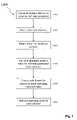
- FIG. 1is a flow diagram of an exemplary embodiment of a method 1000 of the present invention. Note that although various activities are presented in a numbered sequence, and are connected with arrows to an exemplary embodiment of method 1000 , there is no general requirement that the activities be performed in any particular order or any particular number of times, or that all activities be performed. Moreover, any activity can be performed automatically and/or manually.
- a value for a fail-state parameter of the controlled devicecan be determined.
- the determined valuecan be entered into and stored in a memory of the multiple channel discrete output module.
- the memorycan contain numerous single-channel-dedicated fail-state parameter values.
- the multiple channel discrete output modulecan detect a failure or shutdown of the control system, the programmable logic controller, and/or a central processing unit. In certain embodiments, the multiple channel discrete output module can detect a failure of a signal and/or an error in the signal from the control system, the programmable logic controller, and/or a central processing unit. In certain embodiments, the output module can correct the error, acknowledge the signal, and/or further process the signal.
- the multiple channel discrete output modulecan, for each of its channels, or at least several of its multiple channels, retrieve the stored value of the fail-state parameter from the memory of the multiple channel discrete output module, and/or from a memory coupled thereto. In certain embodiments, the multiple channel discrete output module can process, analyze, and/or interpret the stored value.
- the multiple channel discrete output modulecan cause each channel to operate in a mode matching the retrieved fail-state value for that channel. That is, for each of the controlled channels, the multiple channel discrete output module can send a device control signal to the controlled device, the device control signal corresponding to the stored value of the fail-state parameter. Thus, the multiple channel discrete output module can cause each channel to operate in a mode corresponding to the module-stored value for the channel's fail-state parameter.
- the multiple channel discrete output modulecan control a supply of alternating current (AC) and/or direct current (DC) to the controlled device.
- the multiple channel discrete output modulecan control an upper AC supply voltage of about 20 volts to about 240 volts, and every value and range therebetween.
- the multiple channel discrete output modulecan control an upper DC supply voltage of about 20 volts to about 240 volts, and every value and range therebetween.
- the multiple channel discrete output modulecan indicate the device control signal sent to the controlled device, a status of each channel, and/or an operating mode of each channel.
- the indicationcan be provided visually, such as via a lamp, light, strobe, LED, OLED, LCD, display, monitor, electric paper, flag, etc., and/or audibly, such as via a horn, annunciator, beeper, whistle, speaker, siren, etc.
- the multiple channel discrete output modulecan communicate information regarding the device control signal, a status of each channel, and/or an operating mode of each channel, for example, to the control system, PLC, and/or CPU.
- the multiple channel discrete output modulecan communicate other information regarding the device control signal, a status of each channel, and/or an operating mode of each channel.
- the output modulecan communicate an open-circuit status and/or a short-circuit status of a channel.
- the multiple channel discrete output modulecan configure and control each of the multiple channels coupled thereto independently of each of the other channels.
- FIG. 2is a block diagram of an exemplary embodiment of a system 2000 of the present invention.
- system 2000can be viewed as illustrative, and unless specified otherwise, should not be construed to limit the implementation of method 1000 and/or the scope of any claims attached hereto.
- System 2000can comprise a control system, programmable logic controller (PLC), and/or central processing unit 2100 , which can be coupled via a network 2200 to output device and/or module 2300 , such as a multiple channel discrete output module.
- Network 2200can be a wired and/or wireless connection and/or communication network, such as for example, a packet switched network, a connectionless network, an IP network, the Internet, a non-POTS network, and/or a non-PSTN network.
- network 2200can be an IEEE 802.03 wired Ethernet network, an 802.11 wireless network, a wireless serial network, a Bluetooth network, an Ultra Wide Band (UWB) network, an X-10 network, an electrical power network, etc.
- UWBUltra Wide Band
- output device 2300can include at least one opto-coupler, detector, processor, memory, relay, SCR, FET, and/or network interface.
- output device 2300can be coupled to and/or control various controlled devices, such as a relay 2400 , a starter, motor control center, and/or actuator 2500 , visual indicator 2600 (e.g., a lamp, light, strobe, LED, OLED, LCD, display, monitor, electric paper, flag, etc.), an audible indicator 2700 (e.g., a horn, annunciator, beeper, whistle, speaker, siren, etc.), a sensor 2800 (e.g., a sensor of pressure, temperature, flow, mass, heat, light, sound, humidity, proximity, position, velocity, vibration, voltage, current, capacitance, resistance, inductance, electromagnetic radiation, etc.), and/or input device 2900 to CPU 2100 .
- a relay 2400e.g., a starter, motor control center, and/or actuator 2500
- visual indicator 2600e.g., a lamp, light, strobe, LED, OLED, LCD, display, monitor, electric paper, flag,
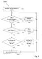
- FIG. 3is a flow diagram of an exemplary embodiment of a method 3000 of the present invention. Note that although various activities are presented in a numbered sequence, and are connected with arrows to an exemplary embodiment of method 3000 , there is no general requirement that the activities be performed in any particular order or any particular number of times, or that all activities be performed. Moreover, any activity can be performed automatically and/or manually.
- the output modulecan be initialized and parameterized. That is, values for the fail-state parameter can be determined, entered into a memory of the output module, and the module activated.
- a usercan determine the values for one or more fail-state parameters, and provide them to the control system, PLC, and/or CPU (the word “CPU” will be used for the remainder of the description of method 3000 , yet in various embodiments the word “control system” and/or “PLC” can be substituted for “CPU”).
- the determined valuescan be communicated to the module from the CPU.
- the CPUcan check for a proper error handler to help it recover from the error without halting program execution. If this error handler is not available or cannot properly handle the error, the CPU can enter a Stop state, which can cause an Output Disable command to all output modules.
- the modulecan determine whether it has received an “Output Disable” command (or the like), whether it has detected a communication failure with the CPU, whether the CPU has failed, and/or whether the CPU has shutdown. If not, at activity 3300 , the module can continue with its normal control operation.
- the modulecan determine whether it should zero all of its outputs. If so, at activity 3500 , the module can provide a zero voltage on each of its channels. If not, at activity 3600 , the module can determine whether it should set any of its outputs (i.e., channels) to a mode corresponding to a stored value for a fail-state parameter for that output.
- the modulecan set each such output to the operating mode corresponding to the stored fail-state. If not, at activity 3800 , the module can hold the channel to the last output state that the module was providing for that channel.
- FIG. 4is a block diagram of an exemplary embodiment of an output device 4000 of the present invention.
- Output device 4000can include well-known components such as one or more communication interfaces 4100 , one or more processors 4200 , one or more memories 4300 containing instructions 4400 , and/or one or more input/output (I/O) devices 4500 , etc.
- I/Oinput/output
- communication interface 4100can be and/or include a bus, connector, network adapter, wireless network interface, wired network interface, modem, radio receiver, transceiver, and/or antenna, etc.
- Each processor 4200can be a commercially available general-purpose microprocessor.
- the processorcan be an Application Specific Integrated Circuit (ASIC) or a Field Programmable Gate Array (FPGA) that has been designed to implement in its hardware and/or firmware at least a part of a method in accordance with an embodiment of the present invention.
- ASICApplication Specific Integrated Circuit
- FPGAField Programmable Gate Array
- Memory 4300can be coupled to processor 3200 and can comprise any device capable of storing analog or digital information, such as a hard disk, Random Access Memory (RAM), Read Only Memory (ROM), flash memory, a compact disk, a digital versatile disk (DVD), a magnetic tape, a floppy disk, and any combination thereof.
- Memory 4300can also comprise a database, an archive, and/or any stored data and/or instructions.
- memory 4300can store instructions 4400 adapted to be executed by processor 4200 according to one or more activities of a method of the present invention.
- Instructions 4400can be embodied in software, which can take any of numerous forms that are well known in the art. Instructions 4400 can control operation of output device 4000 and/or one or more other devices, systems, or subsystems coupled thereto.
- I/O device 4500can be an audio and/or visual device, including, for example, a monitor, display, indicator, light, keyboard, keypad, touchpad, pointing device, microphone, speaker, telephone, fax, video camera, camera, scanner, and/or printer, including a port to which an I/O device can be attached, connected, and/or coupled.
- a monitordisplay, indicator, light, keyboard, keypad, touchpad, pointing device, microphone, speaker, telephone, fax, video camera, camera, scanner, and/or printer, including a port to which an I/O device can be attached, connected, and/or coupled.
Landscapes
- Physics & Mathematics (AREA)
- General Physics & Mathematics (AREA)
- Engineering & Computer Science (AREA)
- Automation & Control Theory (AREA)
- Programmable Controllers (AREA)
- Safety Devices In Control Systems (AREA)
Abstract
Description
Claims (29)
Priority Applications (3)
| Application Number | Priority Date | Filing Date | Title |
|---|---|---|---|
| US10/365,115US7325162B2 (en) | 2002-03-28 | 2003-02-12 | Configurable multiple channel discrete output module |
| EP03075846.0AEP1365298B1 (en) | 2002-03-28 | 2003-03-25 | Configurable multiple channel discrete output module |
| CN03128637ACN100595702C (en) | 2002-03-28 | 2003-03-28 | Configurable Multi-Channel Discrete Output Modules |
Applications Claiming Priority (2)
| Application Number | Priority Date | Filing Date | Title |
|---|---|---|---|
| US36835502P | 2002-03-28 | 2002-03-28 | |
| US10/365,115US7325162B2 (en) | 2002-03-28 | 2003-02-12 | Configurable multiple channel discrete output module |
Publications (2)
| Publication Number | Publication Date |
|---|---|
| US20040078627A1 US20040078627A1 (en) | 2004-04-22 |
| US7325162B2true US7325162B2 (en) | 2008-01-29 |
Family
ID=28794318
Family Applications (1)
| Application Number | Title | Priority Date | Filing Date |
|---|---|---|---|
| US10/365,115Expired - LifetimeUS7325162B2 (en) | 2002-03-28 | 2003-02-12 | Configurable multiple channel discrete output module |
Country Status (3)
| Country | Link |
|---|---|
| US (1) | US7325162B2 (en) |
| EP (1) | EP1365298B1 (en) |
| CN (1) | CN100595702C (en) |
Cited By (3)
| Publication number | Priority date | Publication date | Assignee | Title |
|---|---|---|---|---|
| US8278779B2 (en) | 2011-02-07 | 2012-10-02 | General Electric Company | System and method for providing redundant power to a device |
| US20140122942A1 (en)* | 2012-10-29 | 2014-05-01 | Infineon Technologies Ag | Error signal handling unit, device and method for outputting an error condition signal |
| TWI567549B (en)* | 2014-09-10 | 2017-01-21 | 英業達股份有限公司 | Server and method of detecting the same |
Citations (17)
| Publication number | Priority date | Publication date | Assignee | Title |
|---|---|---|---|---|
| US4189765A (en)* | 1978-03-27 | 1980-02-19 | Robertshaw Controls Company | Digital controller |
| US4265262A (en)* | 1979-03-19 | 1981-05-05 | William Hotine | Fluent material level control system |
| US4870564A (en) | 1984-06-04 | 1989-09-26 | Ge Fanuc Automation North America, Inc. | Distributed input/output system |
| EP0359566A2 (en) | 1988-09-14 | 1990-03-21 | Matsushita Electric Works, Ltd. | I/O relay interface module |
| US4965714A (en)* | 1988-10-28 | 1990-10-23 | Honeywell Inc. | Apparatus for providing configurable safe-state outputs in a failure mode |
| US5099442A (en)* | 1989-11-04 | 1992-03-24 | Ohkura Electric Co., Ltd. | Furnace temperature control apparatus using adjustment input |
| EP0743529A1 (en) | 1995-05-16 | 1996-11-20 | STMicroelectronics S.r.l. | Method and corresponding circuit for detecting an openload |
| US5592373A (en) | 1993-11-18 | 1997-01-07 | Siemens Aktiengesellschaft | Method and apparatus for configuring an automation system |
| WO2000028390A1 (en) | 1998-11-09 | 2000-05-18 | Siemens Aktiengesellschaft | Method for monitoring an output unit |
| US20010003804A1 (en)* | 1997-09-10 | 2001-06-14 | Schneider Automation Inc. | Web interface to a programmable controller |
| WO2001046765A1 (en) | 1999-12-22 | 2001-06-28 | Rockwell Technologies, Llc | Safety network for industrial controller having reduced bandwidth requirements |
| US6256293B1 (en)* | 1995-12-29 | 2001-07-03 | Tellabs Operations, Inc. | Fault management in a multichannel transmission system |
| WO2001059559A1 (en) | 2000-02-08 | 2001-08-16 | Carling Technologies, Inc. | Apparatus for electrically controlling devices, and a method of operating it |
| WO2001081820A1 (en) | 2000-04-22 | 2001-11-01 | Pilz Gmbh & Co. | Modular safety switchgear system |
| US6377859B1 (en)* | 1996-10-04 | 2002-04-23 | Fisher Controls International, Inc. | Maintenance interface device for a use in a process control network |
| US6574740B1 (en)* | 1998-12-07 | 2003-06-03 | International Business Machines Corporation | Dynamic power consumption control for a computer or other electronic apparatus |
| US6868309B1 (en)* | 2001-09-24 | 2005-03-15 | Aksys, Ltd. | Dialysis machine with symmetric multi-processing (SMP) control system and method of operation |
- 2003
- 2003-02-12USUS10/365,115patent/US7325162B2/ennot_activeExpired - Lifetime
- 2003-03-25EPEP03075846.0Apatent/EP1365298B1/ennot_activeExpired - Lifetime
- 2003-03-28CNCN03128637Apatent/CN100595702C/ennot_activeExpired - Lifetime
Patent Citations (18)
| Publication number | Priority date | Publication date | Assignee | Title |
|---|---|---|---|---|
| US4189765A (en)* | 1978-03-27 | 1980-02-19 | Robertshaw Controls Company | Digital controller |
| US4265262A (en)* | 1979-03-19 | 1981-05-05 | William Hotine | Fluent material level control system |
| US4870564A (en) | 1984-06-04 | 1989-09-26 | Ge Fanuc Automation North America, Inc. | Distributed input/output system |
| EP0359566A2 (en) | 1988-09-14 | 1990-03-21 | Matsushita Electric Works, Ltd. | I/O relay interface module |
| US4965714A (en)* | 1988-10-28 | 1990-10-23 | Honeywell Inc. | Apparatus for providing configurable safe-state outputs in a failure mode |
| US5099442A (en)* | 1989-11-04 | 1992-03-24 | Ohkura Electric Co., Ltd. | Furnace temperature control apparatus using adjustment input |
| US5592373A (en) | 1993-11-18 | 1997-01-07 | Siemens Aktiengesellschaft | Method and apparatus for configuring an automation system |
| EP0743529A1 (en) | 1995-05-16 | 1996-11-20 | STMicroelectronics S.r.l. | Method and corresponding circuit for detecting an openload |
| US20010043563A1 (en)* | 1995-12-29 | 2001-11-22 | Gerstel Ornan Alexander | Fault management in a multichannel transmission system |
| US6256293B1 (en)* | 1995-12-29 | 2001-07-03 | Tellabs Operations, Inc. | Fault management in a multichannel transmission system |
| US6377859B1 (en)* | 1996-10-04 | 2002-04-23 | Fisher Controls International, Inc. | Maintenance interface device for a use in a process control network |
| US20010003804A1 (en)* | 1997-09-10 | 2001-06-14 | Schneider Automation Inc. | Web interface to a programmable controller |
| WO2000028390A1 (en) | 1998-11-09 | 2000-05-18 | Siemens Aktiengesellschaft | Method for monitoring an output unit |
| US6574740B1 (en)* | 1998-12-07 | 2003-06-03 | International Business Machines Corporation | Dynamic power consumption control for a computer or other electronic apparatus |
| WO2001046765A1 (en) | 1999-12-22 | 2001-06-28 | Rockwell Technologies, Llc | Safety network for industrial controller having reduced bandwidth requirements |
| WO2001059559A1 (en) | 2000-02-08 | 2001-08-16 | Carling Technologies, Inc. | Apparatus for electrically controlling devices, and a method of operating it |
| WO2001081820A1 (en) | 2000-04-22 | 2001-11-01 | Pilz Gmbh & Co. | Modular safety switchgear system |
| US6868309B1 (en)* | 2001-09-24 | 2005-03-15 | Aksys, Ltd. | Dialysis machine with symmetric multi-processing (SMP) control system and method of operation |
Cited By (4)
| Publication number | Priority date | Publication date | Assignee | Title |
|---|---|---|---|---|
| US8278779B2 (en) | 2011-02-07 | 2012-10-02 | General Electric Company | System and method for providing redundant power to a device |
| US20140122942A1 (en)* | 2012-10-29 | 2014-05-01 | Infineon Technologies Ag | Error signal handling unit, device and method for outputting an error condition signal |
| US9218236B2 (en)* | 2012-10-29 | 2015-12-22 | Infineon Technologies Ag | Error signal handling unit, device and method for outputting an error condition signal |
| TWI567549B (en)* | 2014-09-10 | 2017-01-21 | 英業達股份有限公司 | Server and method of detecting the same |
Also Published As
| Publication number | Publication date |
|---|---|
| CN100595702C (en) | 2010-03-24 |
| CN1450429A (en) | 2003-10-22 |
| EP1365298A2 (en) | 2003-11-26 |
| EP1365298B1 (en) | 2020-06-03 |
| EP1365298A3 (en) | 2004-10-27 |
| US20040078627A1 (en) | 2004-04-22 |
Similar Documents
| Publication | Publication Date | Title |
|---|---|---|
| EP2080071B1 (en) | Handheld field maintenance bus monitor | |
| US9607494B2 (en) | Supervised interconnect smoke alarm system and method of using same | |
| US20090253388A1 (en) | Rf adapter for field device with low voltage intrinsic safety clamping | |
| US7325162B2 (en) | Configurable multiple channel discrete output module | |
| US7085963B2 (en) | Method for configuring a multiple channel discrete output module | |
| JPH06266987A (en) | Disaster prevention monitoring device | |
| JP2007071840A (en) | Electronic control unit | |
| JP2002150449A (en) | Gas leak alarm system and ventilation method | |
| US6507283B1 (en) | Self-validating output module | |
| CN110778514B (en) | Fan control system | |
| US20240219051A1 (en) | Device and method for detection of electrical discharge in anhvac control box | |
| JP3463134B2 (en) | Communication device | |
| JP3428331B2 (en) | Distributed control system | |
| CN217359831U (en) | Ozone concentration monitoring devices and air conditioning unit | |
| CN110389539A (en) | Safety switch | |
| EP4455574A1 (en) | Device and method for analyzing and discriminating faults in an hvac system | |
| KR102513475B1 (en) | Apparatus for assisting opening/closing of circuit breaker | |
| JP2018142811A (en) | Load current control device | |
| JPH10188154A (en) | Sensor and supervisory and control system | |
| CN119052743A (en) | Container monitoring device and container | |
| JP2005122661A (en) | Fire receiving unit | |
| JP5507413B2 (en) | Sensor base and monitoring system | |
| JPH0567142U (en) | DC power supply interface circuit | |
| JP2011086075A (en) | Functional inspection method for alarm and the alarm | |
| JPH08304105A (en) | Encoder signal reset method |
Legal Events
| Date | Code | Title | Description |
|---|---|---|---|
| AS | Assignment | Owner name:SIEMENS ENERGY & AUTOMATION, INC., GEORGIA Free format text:ASSIGNMENT OF ASSIGNORS INTEREST;ASSIGNORS:WEDDLE, ALAN;MOWRY, STEPHEN WEEKS;REEL/FRAME:014053/0867 Effective date:20030321 | |
| STCF | Information on status: patent grant | Free format text:PATENTED CASE | |
| AS | Assignment | Owner name:SIEMENS INDUSTRY, INC.,GEORGIA Free format text:MERGER;ASSIGNOR:SIEMENS ENERGY AND AUTOMATION AND SIEMENS BUILDING TECHNOLOGIES, INC.;REEL/FRAME:024411/0223 Effective date:20090923 Owner name:SIEMENS INDUSTRY, INC., GEORGIA Free format text:MERGER;ASSIGNOR:SIEMENS ENERGY AND AUTOMATION AND SIEMENS BUILDING TECHNOLOGIES, INC.;REEL/FRAME:024411/0223 Effective date:20090923 | |
| FPAY | Fee payment | Year of fee payment:4 | |
| FPAY | Fee payment | Year of fee payment:8 | |
| MAFP | Maintenance fee payment | Free format text:PAYMENT OF MAINTENANCE FEE, 12TH YEAR, LARGE ENTITY (ORIGINAL EVENT CODE: M1553); ENTITY STATUS OF PATENT OWNER: LARGE ENTITY Year of fee payment:12 | |
| AS | Assignment | Owner name:SIEMENS AKTIENGESELLSCHAFT, GERMANY Free format text:ASSIGNMENT OF ASSIGNORS INTEREST;ASSIGNOR:SIEMENS INDUSTRY, INC.;REEL/FRAME:052145/0464 Effective date:20191029 |