US7324695B2 - Prioritized image visualization from scalable compressed data - Google Patents
Prioritized image visualization from scalable compressed dataDownload PDFInfo
- Publication number
- US7324695B2 US7324695B2US11/057,977US5797705AUS7324695B2US 7324695 B2US7324695 B2US 7324695B2US 5797705 AUS5797705 AUS 5797705AUS 7324695 B2US7324695 B2US 7324695B2
- Authority
- US
- United States
- Prior art keywords
- bin
- data
- prioritized
- compressed data
- client
- Prior art date
- Legal status (The legal status is an assumption and is not a legal conclusion. Google has not performed a legal analysis and makes no representation as to the accuracy of the status listed.)
- Expired - Lifetime, expires
Links
Images


Classifications
- H—ELECTRICITY
- H04—ELECTRIC COMMUNICATION TECHNIQUE
- H04L—TRANSMISSION OF DIGITAL INFORMATION, e.g. TELEGRAPHIC COMMUNICATION
- H04L69/00—Network arrangements, protocols or services independent of the application payload and not provided for in the other groups of this subclass
- H04L69/04—Protocols for data compression, e.g. ROHC
Definitions
- MRIMagnetic Resonance Imaging
- USUltrasound
- CTComputed Tomography
- PETPositron Emission Tomography
- SPECTSingle Photon Emission Computed Tomography
- volumetric data setsare massive.
- the “Visible Male” data setincludes axial scans of the entire body taken at 1 mm intervals at a resolution of 512 by 512 pixels.
- the whole data sethas 1870 cross sections, and consumes about 15 GBytes of voxel data.
- the “Visible Woman” data setincludes cross sectional images at one-third the sampling interval of the “Visible Male” along the axial direction, and consumes about 40 GBytes.
- the compression schemeshould support both lossy and lossless compression. Lossy compression allows the user to trade image quality for reduced bit-rates. On the other hand, there are situations where lossless reconstruction is important, such as where small image details might influence the detection of pathology and could alter the diagnosis.
- the compression schemeshould support eight, 12 and 16 bit signed or unsigned data, which is typical of medical images. In general, it should preferably support arbitrary bit-depths.
- the benefit of compressioncan be significantly enhanced if the entire data set does not have to be decompressed prior to visualization.
- the data transmitted by the servershould be scalable by resolution. This enables a client to browse a low-resolution version of the volume and appropriately choose a volume of interest (VOI). Distortion scalability is also of interest, so that the VOI of the client is progressively refined by quality.
- VOIvolume of interest
- the compression technologyshould be based on a multi-resolution framework, with reduced resolution viewing making it possible to save on compressed data transmitted through the network as well as rendering time.
- volume renderinguses a transfer function that maps from voxel intensity values to color and opacity values. What is currently needed is an improved technique for prioritized image visualization from scalable compressed data.
- a system embodimentincludes a database server for receiving an interactive prioritization request from a client and prioritizing transmission of the compressed data relative to a bin optimization in response to the interactive prioritization request.
- a corresponding method embodimentincludes receiving an interactive prioritization request from a client, prioritizing transmission of the compressed data relative to the bin optimization in response to the interactive prioritization request and transmitting the prioritized compressed data to the client.
- the present disclosureteaches prioritized image visualization from scalable compressed data in accordance with the following exemplary figures, in which:
- FIG. 1shows a schematic diagram of a client-server model in accordance with an exemplary embodiment of the present disclosure
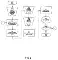
- FIG. 2shows a flowchart diagram for prioritized image visualization from scalable compressed data in accordance with an exemplary embodiment of the present disclosure
- FIG. 3shows a graphical diagram of bin and code-block masks in accordance with an exemplary embodiment of the present disclosure
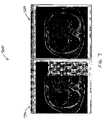
- FIG. 4shows a graphical diagram of comparative volume slices including a slice with bin-optimized delivery in accordance with an exemplary embodiment of the present disclosure
- FIG. 5shows a graphical diagram for peak signal-to-noise ratios (PSNR) as a function of the data transmitted by the server with and without bin-optimized delivery in accordance with an exemplary embodiment of the present disclosure
- FIG. 6shows a graphical diagram for a bin mask and a code-block mask corresponding to the bin mask in accordance with an exemplary embodiment of the present disclosure
- FIG. 7shows a graphical diagram for prioritized delivery using the bin-mask of FIG. 6 ;
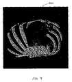
- FIG. 8shows a graphical diagram for bone rendered from an uncompressed volume
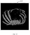
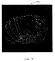
- FIG. 9shows a graphical diagram for bone rendered after 1.5 MB of prioritized transmission for the bone bin in accordance with an exemplary embodiment of the present disclosure
- FIG. 10shows a graphical diagram for bone rendered after 1.5 MB of default non-prioritized transmission
- FIG. 11shows a graphical diagram for bone rendered after 2 MB of prioritized transmission for the bone bin in accordance with an exemplary embodiment of the present disclosure
- FIG. 12shows a graphical diagram for bone rendered after 2 MB of default non-prioritized transmission
- FIG. 13shows a graphical difference diagram between FIGS. 11 and 8 ;
- FIG. 14shows a graphical difference diagram between FIGS. 12 and 8 .
- a system and method for prioritized image visualization from scalable compressed dataare provided.
- a variety of visualization schemesmay be employed to visualize voxel data.
- an intelligent server embodimentprioritizes the compressed data packets based on their potential contributions to the rendered display output.
- JPEG2000has been extended in Part 2 of the standard to provide a specification of the Discrete Wavelet Transform (DWT) along the component direction.
- DCTDiscrete Cosine Transform
- An exemplary embodiment of the present disclosureuses scalable compressed data compliant with the JPEG2000 standard.
- Other types of scalable compressed datamay be used in alternate embodiments, such as data compliant with the proposed MPEG Scalable Video Coder (MPEG SVC), and the like.
- MPEG SVCMPEG Scalable Video Coder
- JPEG2000is highly scalable and supports the extension of two-dimensional (2D) algorithms to support volumes.
- 2Dtwo-dimensional
- 3D-SPIHTthree-dimensional reversible integer wavelet transform combined with EZW
- Embodiments of the present disclosureinclude schemes that use JPEG2000 and JPIP (JPEG2000 Interactive Protocol) to transmit data in a multi-resolution and progressive fashion.
- the serverexploits the spatial locality offered by the wavelet transform and packet indexing information to transmit compressed volume data relevant to a client's particular query.
- VOIvolume of interest
- Contextual background informationcan also be provided with a quality fading away from the VOI.
- a prioritizationenables the client to progressively visualize scene content from a compressed file.
- the clientmakes requests to progressively receive data corresponding to any particular tissue type.
- the serveris now capable of re-ordering the same compressed data file on the fly to serve data packets prioritized as per the client's request.
- the interactive userhas the freedom to browse and render any sub-section of the volume at variable resolution with varying levels of visual quality, and is also able to visualize any arbitrary set of tissue types with enhanced quality.
- the resulting system embodimentis ideally suited for bandwidth-constrained systems having compressed volume data on a server that is to be browsed by a client.
- a client-server modelis indicated generally by the reference numeral 100 .
- the client-server 100includes a server 110 and a client 120 in signal communication with the server.
- the server 110includes a database server 112 , a transcoder 114 in signal communication with the database server, and a cache model 116 in signal communication with the transcoder.
- the client 120includes a decompressor 122 , a rendering engine 124 in signal communication with the decompressor, and a cache 126 in signal communication with the rendering engine.
- the method 200includes a start block 210 that passes control to an input/output (I/O) block 212 .
- I/Oinput/output
- a clientrequests prioritized compressed data from a server, and control is passed to a function block 214 .
- the servertranscodes the compressed data for bin prioritization, and control is passed to a function block 216 .
- the servermaintains its cache model of client's cache, and control is passed to an I/O block 218 .
- the servertransmits prioritized compressed data to the client, and control is passed to an I/O block 220 .
- the clientreceives the prioritized compressed data from the server, and control is passed to a function block 222 .
- the clientdecompresses the prioritized data, and control is passed to a function block 224 .
- the clientrenders the prioritized data, and control is passed to a display block 226 .
- the clientdisplays the prioritized data, and control is passed to a decision block 228 .
- the block 228determines whether the client requires more data, and if so control is passed back to the function block 214 . On the other hand, if the client does not require more data, control is passed to an end block 230 .
- masks of bone data from a slice of a volumetric data setare indicated generally by the reference numeral 300 .
- the masksinclude a bin mask 310 and a code-block mask 320 , showing the relevant code-blocks on the sub-band domain.
- Four levels of transformwere applied along the x, y and z directions to obtain the masks.
- volume slices illustrating the effect of bin-optimized deliveryare indicated generally by the reference numeral 400 .
- One slice 410 without bin-optimized delivery and another slice 420 with bin-optimized deliveryare displayed at a stage when roughly the same amount of compressed data, or about 3 MBytes, has been transmitted from the same compressed file by the server.
- the common compressed filecontains 256 slices, compressed with four levels of transform along the three dimensions.
- the bonewas requested by the client. All slices were transmitted by the server and decompressed by the client, with relevant precincts transmitted with higher fidelity.
- the regions corresponding to the bonehave a higher visual quality at the cost of a poorer visual quality in the regions at the center.
- PSNRpeak signal-to-noise ratios
- a bin mask 610corresponds to bone confined to the left half of the volume
- a code-block mask 620corresponds to the bin mask
- the result 720has reduced blockiness due to increased emphasis of the entire LLDxy band.
- bone rendered after the complete uncompressed volume has been received by the clientis indicated generally by the reference numeral 800 .
- bone rendered after 1.5 MB of prioritized transmission for the bone bin has been received by the clientis indicated generally by the reference numeral 900 .
- the observed PSNR values for the bone, background and the entire volumeare 40.25, 40.15 and 40.15 dB, respectively.
- bone rendered after 1.5 MB of default or non-prioritized transmission has been received by the clientis indicated generally by the reference numeral 1000 .
- the observed PSNR values for the bone, background and the entire volumeare 34.05, 40.72 and 40.51 dB, respectively.
- bone rendered after 2 MB of prioritized transmission for the bone bin has been received by the clientis indicated generally by the reference numeral 1100 .
- the observed PSNR values for the bone, background and the entire volumeare 41.73, 40.44 and 40.46 dB, respectively.
- bone rendered after 2 MB of default or non-prioritized transmission has been received by the clientis indicated generally by the reference numeral 1200 .
- the observed PSNR values for the bone, background and the entire volumeare 35.06, 41.16 and 35.08 dB, respectively.
- FIG. 13a difference image between the renderings 1100 of FIGS. 11 and 800 of FIG. 8 is indicated generally by the reference numeral 1300 . This is the difference between 2 MB of prioritized transmission versus the whole uncompressed data set.
- FIG. 14a difference image between the renderings 1200 of FIGS. 12 and 800 of FIG. 8 is indicated generally by the reference numeral 1400 . This is the difference between 2 MB of default or non-prioritized transmission versus the whole uncompressed data set.
- volumetric data setsmay be quite large, so memory and disk caching schemes are used to improve performance.
- the client 120 of FIG. 1maintains a cache 126 of data transmitted by the server, and is able to delete elements from the cache once they are outside the VOI of an interactive user.
- the servermaintains the model 116 of the client's cache, to avoid resending any elements that the client already has in its cache.
- the need for the server to be aware of the client's cache contentsis particularly important in wavelet based compression schemes, since even two VOI's can have significant overlap of compressed data.
- the communication protocolallows the client to communicate its cache state to the server.
- the communication protocol between the client 120 and the server 110preferably employs a generic protocol that is easily deployed on a variety of channels.
- the client-server protocolis transport neutral, and each packet returned by the server is a self-contained unit. This feature stems from the fact that packets may be received out of order and that the client should not have to wait to improve its cache. Such a scheme becomes increasingly important when transport protocols with very few error recovery services and/or high packet erasure channels are employed. In such cases, absence of such a self-contained scheme would mean that the client would have to wait until the server resent lost packets.
- volumetric data setsmay be stored and maintained by the database server 112 , so that one or more remote clients 120 can browse the data sets interactively.
- a clientmay be a low-end workstation with limited bandwidth, memory and processing power.
- One of the fundamental needs of a clientis breadth in terms of interactivity under a variety of network conditions. For example, an interactive user may need reduced resolution viewing, the ability to view a select subsection of the volume, and the ability to pan, zoom, and view select slices, all with a pleasant and real-time viewing experience exhibiting immediate and progressive refinement of the view volume.
- a useris generally willing to initially sacrifice some rendering quality or field of view in exchange for real-time performance.
- a usersuch as a radiologist or clinician, may also need to browse the data set slice by slice or to visualize the volume to get an overview.
- the bin mask 310yields the code-block mask 320 , which, in turn, shows the relevant code-blocks on the sub-band domain.
- Four levels of transformwere applied along the x, y and z directions to obtain the masks.
- the fundamental volume visualization algorithmsare of two types: direct volume rendering (DVR) algorithms and surface-fitting (SF) algorithms.
- DVRincludes approaches such as ray-casting and splatting.
- the disadvantage with DVRis that the entire data set must be traversed for each rendered image. Sometimes a low-resolution image is quickly created to check the volume and then refined, which is called “progressive refinement”.
- SF methodsfit iso-surfaces, such as planar polygons or surface patches, to constant-value contour surfaces. SF methods are usually faster than DVR methods, since they traverse the data set once for a given threshold value. New views of the surface can be quickly generated. However, using a new SF threshold is time consuming since the cells must be revisited to extract new surfaces.
- Data classificationmay involve choosing a scalar threshold value for SF algorithms, or choosing opacity values for DVR algorithms.
- An opacity transfer functionis used to expose the relevant segments and to make transparent the uninteresting ones.
- the pixel intensitygenerally determines the tissue type.
- scalar voxel valuescan play a key role in determining the compressed data of interest to an interactive client.
- the scalar range of the volume datais divided into bins, where each bin represents the intensity range to which a particular tissue is confined. Bins are generally not uniformly spaced. Each voxel is assigned to a particular bin, or may remain unassigned. The compressed volume data corresponding to each bin is identified. For each bin, a bin mask is generated, such as the bin mask 310 of FIG. 3 . The bin mask is the set of voxels that belong to the bin. Due to the finite spatial extent of the DWT, it is possible to trace each voxel to a set of wavelet coefficients using the footprint of the wavelet kernel used to transform the volume data.
- each bin maskwhich is defined on the volume data grid, is mapped to a mask on the sub-band grid. This mask is used to identify if a code-block contributes to a bin.
- the set of code-blocks that contribute to the binforms a code-block mask on the sub-band grid, such as the code-block mask 320 of FIG. 3 .
- the masks 300 of FIG. 3show the bin mask 310 and the code-block mask 320 for one slice of a volume. This procedure requires negligible computational overhead.
- the code-block maskis generated during the volume compression and is a one-time expense. Each voxel's bin is determined as it is read. Due to the smearing effects of the wavelet filter, code-block masks may have some overlap. That is, a code-block may affect more than one tissue type.
- a bin tableis created for identifying the bins on which each code-block bears an influence.
- a field biis included, indicating the percentage of coefficients from the code-block i that contribute to the bin b. This table is stored in a file at the server.
- This table-file for each bin in the uncompressed formmay be represented as a binary volume. One bit is required for each code-block to determine if it contributes to the bin. For a 512 ⁇ 512 ⁇ 256 first exemplary test volume such as a segment of a CT scan of an abdomen, using a code-block size of 8 ⁇ 8, the size of the table-file for a bin was 0.015625 bits/voxel.
- the table-filecan be thought of as a binary mask and can be easily compressed.
- One approach to creating a scalable representationwould be to simply multiply the distortion-rate slopes of the scalar bin of interest, b, by a weight web prior to rate allocation during compression. This would certainly give an enhanced viewing experience for voxels belonging to bin b. However, this creates a pre-defined bin preference in the compressed file. If the client wishes to render another bin, it would require re-compression of the bit-stream. Thus, it is more beneficial to have the server determine and transmit the proper data on the fly from a single compressed code-stream, to provide an enhanced viewing experience in any bin.
- Packet-Length Tile-part (PLAT) marker segmentsare used in the code-stream to provide random access to packets from the code-stream.
- the serveroptionally transcodes the input volume on the fly into one with smaller or resized precincts, which can be as small as the size of the code-block. Transcoding does not consume significant resources since transcoding simply repackages existing code-blocks to conform to smaller precinct sizes, without actually decoding them.
- a transcodersuch as the transcoder 114 of FIG. 1 , thereby provides granularity suitable for interactive visualization.
- the precinctsPrior to delivering the data, the precincts are re-layered into packets to emphasize one or more data bins as chosen by the client.
- the serverdetermines, from the bin-table, the degree to which each precinct P contributes to the code-block mask Bb for the bin b. This is called the bin-relevance Abu of the precinct P, as defined by Equation 1 of Table 1, where N is the number of code-blocks that make up the precinct P.
- the field biis obtained from the bin-table.
- the distortion-rate slopes of each packet from the precinct Pare then weighted by 1+(abp)(wb).
- the weight wbdetermines the level of importance attached to receiving the voxel data corresponding to bin b prior to the rest of the volume. A weight of zero results in the absence of weighting. A weight wb roughly corresponds to a bit-plane shift of the relevant code-block's sub-band coefficients by log 2wb bitplanes.
- the apparent or weighted distortion-rate slopes of the packet from precinct P at layer lare given by Equation 2 of Table 1. Hence, the packets are re-assigned to an upper layer l′ ⁇ l such that Equation 3 of Table 1 is met.
- one slice 410 without bin-optimized delivery and another slice 420 with bin-optimized deliveryare displayed at a stage when roughly the same amount of compressed data has been transmitted from the same compressed file by the server.
- the regions in the other slice 420corresponding to the interactively chosen tissue type of bone in this case, have a higher visual quality than those regions in the slice 410 .
- the JPIP request syntaxitself facilitates the extraction of some regions of interest in the image, they are constrained to be rectangular and would not be applicable in such a case since the bin is scattered over the volume.
- the slices 410 and 420are from an exemplary CT scan of an abdomen after three MBytes of compressed data have been transmitted by the server.
- the common compressed filecontains 256 slices, compressed with four levels of transform along the three dimensions.
- the bonewas requested by the client. All slices were transmitted by the server and decompressed by the client, with relevant precincts transmitted with higher fidelity.
- the white regions of 420 corresponding to the bone of FIG. 3have a higher visual quality at the allowed cost of a poorer visual quality in the non-bone regions at the center.
- the peak signal-to-noise ratios (PSNR) 500 of FIG. 5compare the progressive increase in PSNR of the bin as data is received by the client, with and without bin-optimized delivery. From the figure, it can be seen that the bin-optimized delivery requires roughly 5 MB data transfer to achieve a PSNR of 46 dB for the data within the bin, whereas 11 MB of data need to be transferred to achieve the same reconstruction quality if bin-optimized delivery is not used. By varying the weight web, it is possible to obtain a range of prioritizations within the bin.
- the PSNRsare a function of the data transmitted by the server with and without bin-optimized delivery.
- the PSNR within the binis significantly higher with bin-optimized delivery.
- the PSNR outside the binis also shown.
- the precinct size chosenwas 16 ⁇ 16.
- the code-block size chosenwas 8 ⁇ 8.
- FIG. 5shows the gains obtained with two different weights, 1024 and 8. Higher weights lead to larger gains. It must be emphasized here that data delivery is optimized based on scene content. If it is known, a priori, that bone was the only tissue of interest, the server could have segmented bone out and compressed it in separate file and this would require far less data transmission than the schemes mentioned here. However, the present exemplary application requires that the client have the flexibility to select any type of tissue or segmentation.
- the servercan transcode larger precinct sizes into smaller dimensions in order to increase the granularity for interactive bin delivery.
- this granularityis associated with a slight packaging overhead.
- a packetis the fundamental unit of transmission. Each packet is preceded by a packet header that helps identify its contribution to the code-stream. For a volume with a large number of slices, the net size of the packet headers can also play a minor role. If the intent is to transmit the entire volume, it is clear that larger precinct sizes would be more effective. Smaller precinct sizes result in more packets and hence a large total packet header size.
- precinct dimensionsgive higher PSNR values within the bin, since smaller precincts can provide a more compact representation of the bin.
- Table 2shows the effect of transcoding to smaller precinct sizes.
- the code-block size chosenwas 8 ⁇ 8.
- the PSNRsare tabulated for precinct sizes of 16, 32 and 64 for the two exemplary cases.
- the PSNR with bin-optimized deliveryis higher in the bin of interest, at the calculated cost of a reduction in PSNR for regions away from the bin. If the bin is confined to a small spatial region, the client may see blocky artifacts during the initial stages of the browsing session. This does not happen in the results 400 of FIG. 4 because the smearing effects of the filter result in almost the entire LLDxy band being weighted.
- the bin mask of bone 610confined to the left half of the volume, and the code-block mask 620 corresponding to the bin mask were introduced with respect to FIG. 6 . If a bin consists of bone tissue on the left half of the volume, as in FIG. 6 , one could end up with blocky artifacts as shown in 710 of FIG. 7 . Thus, a more pleasant browsing experience may be obtained by reducing the weight web to an appropriate value.
- a weight function web(cbi)may be applied that progressively decays from the most relevant to the least relevant bins.
- a simpler solutionwould be to weight all of the code-blocks in the LLDxy band with w LLDxy>max(wb) or weight a few low-resolution bands. 700 of FIG. 7 shows the reduction in blockiness obtained by weighting the entire LLDxy band.
- Rendered imagesare compared by applying the prioritization scheme to bone in the exemplary embodiment.
- FIG. 8is rendered from an uncompressed 512 ⁇ 512 ⁇ 256 (xyz) section of the abdomen.
- FIGS. 9 through 12compare the renderings from 1.5 MB and 2 MB of prioritized and uniform transmissions. The differences in the quality of the rendered output are seen in the form of a coarser texture and the presence of additional holes in the absence of prioritization.
- FIGS. 13 and 14show the difference images of the prioritized and the default schemes against the original renderings. It can be seen that the difference map in the prioritized case is much less dense than in the non-prioritized case, illustrating the improvement obtained in the renderings for the client.
- a generic ray-castercasts rays through the volume, processing the scalar voxel values along the ray according to a ray function. Most ray functions use an alpha composting technique, which treats the values along the ray as samples of opacity accumulated per unit distance. The relevance measure, abp should then be a function of the accumulated opacity along the ray as it passes through each code-block.
- the servermay also take advantage of early ray termination.
- subsequent bin-relevance values along the raymay be set to zero.
- Prioritizationin this case is carried out by both the client and the server.
- the serverprioritizes regions of the volume based on opacity for bin-optimized delivery, while the client prioritizes regions of the volume based on visibility.
- the visibility relevance measuresmay be computed by the client once the lowest resolution has been decompressed. Rate-distortion optimized delivery for the bins can then be applied to the subsequent higher resolution sub-bands. As the higher resolution data becomes available at the client, the bin-table may be further refined.
- a wavelet based visualization schemehas been proposed, where the prioritization is entirely carried out by the client and expressed in terms of refined client requests based on visibility estimates from a lower resolution.
- imageas used herein may also represent three-dimensional, four-dimensional, and higher dimensional data sets in alternate embodiments.
- the teachings of the present disclosuremay be implemented in various forms of hardware, software, firmware, special purpose processors, or combinations thereof.
- the softwareis preferably implemented as an application program tangibly embodied on a program storage unit.
- the application programmay be uploaded to, and executed by, a machine comprising any suitable architecture.
- the machineis implemented on a computer platform having hardware such as one or more central processing units (“CPU”), a random access memory (“RAM”), and input/output (“I/O”) interfaces.
- CPUcentral processing units
- RAMrandom access memory
- I/Oinput/output
- the computer platformmay also include an operating system and microinstruction code.
- the various processes and functions described hereinmay be either part of the microinstruction code or part of the application program, or any combination thereof, which may be executed by a CPU.
- various other peripheral unitsmay be connected to the computer platform such as an additional data storage unit and a printing unit.
Landscapes
- Engineering & Computer Science (AREA)
- Computer Security & Cryptography (AREA)
- Computer Networks & Wireless Communication (AREA)
- Signal Processing (AREA)
- Compression Of Band Width Or Redundancy In Fax (AREA)
Abstract
Description
| TABLE 1 | |||
| (Eqn. 1) | |||
| (Eqn. 2) | |||
| (Eqn. 3) | |||
| TABLE 2 | ||
| Precinct size p × p | ||
| 16 | 32 | 64 | ||
| PSNR with | Bone | 48.5336 | 48.1589 | 47.2337 |
| bin-optimized | Rest of the volume | 41.2619 | 44.9162 | 49.1307 |
| delivery (dB) | ||||
| PSNR without | Bone | 46.0163 | 46.2098 | 46.9384 |
| bin-optimized | Rest of the volume | 48.2976 | 49.2109 | 49.5648 |
| delivery (dB) | ||||
Claims (21)
Priority Applications (2)
| Application Number | Priority Date | Filing Date | Title |
|---|---|---|---|
| US11/057,977US7324695B2 (en) | 2002-03-18 | 2005-02-15 | Prioritized image visualization from scalable compressed data |
| DE102005007530ADE102005007530B4 (en) | 2004-02-17 | 2005-02-17 | Prioritized image visualization from scalable compressed data |
Applications Claiming Priority (3)
| Application Number | Priority Date | Filing Date | Title |
|---|---|---|---|
| US10/100,154US7190836B2 (en) | 2002-03-18 | 2002-03-18 | Efficient ordering of data for compression and visualization |
| US54555004P | 2004-02-17 | 2004-02-17 | |
| US11/057,977US7324695B2 (en) | 2002-03-18 | 2005-02-15 | Prioritized image visualization from scalable compressed data |
Related Parent Applications (1)
| Application Number | Title | Priority Date | Filing Date |
|---|---|---|---|
| US10/100,154Continuation-In-PartUS7190836B2 (en) | 2002-03-18 | 2002-03-18 | Efficient ordering of data for compression and visualization |
Publications (2)
| Publication Number | Publication Date |
|---|---|
| US20060031372A1 US20060031372A1 (en) | 2006-02-09 |
| US7324695B2true US7324695B2 (en) | 2008-01-29 |
Family
ID=34889868
Family Applications (1)
| Application Number | Title | Priority Date | Filing Date |
|---|---|---|---|
| US11/057,977Expired - LifetimeUS7324695B2 (en) | 2002-03-18 | 2005-02-15 | Prioritized image visualization from scalable compressed data |
Country Status (2)
| Country | Link |
|---|---|
| US (1) | US7324695B2 (en) |
| DE (1) | DE102005007530B4 (en) |
Cited By (36)
| Publication number | Priority date | Publication date | Assignee | Title |
|---|---|---|---|---|
| US20070051817A1 (en)* | 2005-09-02 | 2007-03-08 | Takanori Yano | Image processing apparatus and image processing method |
| US20080219570A1 (en)* | 2007-02-28 | 2008-09-11 | Siemens Corporate Research, Inc. | Methods and systems for remotely visualizing images |
| US20080240548A1 (en)* | 2007-03-28 | 2008-10-02 | Terence Sern-Wei Yeoh | Isosurfacial three-dimensional imaging system and method |
| US20090276186A1 (en)* | 2008-05-02 | 2009-11-05 | Inguran, Llc | Flow cytometer remote monitoring system |
| US20100220796A1 (en)* | 2007-10-16 | 2010-09-02 | Peng Yin | Methods and apparatus for artifact removal for bit depth scalability |
| US20110054798A1 (en)* | 2008-05-02 | 2011-03-03 | Inguran, Llc | Flow cytometer remote monitoring system |
| US20110214082A1 (en)* | 2010-02-28 | 2011-09-01 | Osterhout Group, Inc. | Projection triggering through an external marker in an augmented reality eyepiece |
| US20110221897A1 (en)* | 2010-02-28 | 2011-09-15 | Osterhout Group, Inc. | Eyepiece with waveguide for rectilinear content display with the long axis approximately horizontal |
| US8184069B1 (en) | 2011-06-20 | 2012-05-22 | Google Inc. | Systems and methods for adaptive transmission of data |
| US8467133B2 (en) | 2010-02-28 | 2013-06-18 | Osterhout Group, Inc. | See-through display with an optical assembly including a wedge-shaped illumination system |
| US8472120B2 (en) | 2010-02-28 | 2013-06-25 | Osterhout Group, Inc. | See-through near-eye display glasses with a small scale image source |
| US8477425B2 (en) | 2010-02-28 | 2013-07-02 | Osterhout Group, Inc. | See-through near-eye display glasses including a partially reflective, partially transmitting optical element |
| US8482859B2 (en) | 2010-02-28 | 2013-07-09 | Osterhout Group, Inc. | See-through near-eye display glasses wherein image light is transmitted to and reflected from an optically flat film |
| US8488246B2 (en) | 2010-02-28 | 2013-07-16 | Osterhout Group, Inc. | See-through near-eye display glasses including a curved polarizing film in the image source, a partially reflective, partially transmitting optical element and an optically flat film |
| US9091851B2 (en) | 2010-02-28 | 2015-07-28 | Microsoft Technology Licensing, Llc | Light control in head mounted displays |
| US9097890B2 (en) | 2010-02-28 | 2015-08-04 | Microsoft Technology Licensing, Llc | Grating in a light transmissive illumination system for see-through near-eye display glasses |
| US9097891B2 (en) | 2010-02-28 | 2015-08-04 | Microsoft Technology Licensing, Llc | See-through near-eye display glasses including an auto-brightness control for the display brightness based on the brightness in the environment |
| US9129295B2 (en) | 2010-02-28 | 2015-09-08 | Microsoft Technology Licensing, Llc | See-through near-eye display glasses with a fast response photochromic film system for quick transition from dark to clear |
| US9128281B2 (en) | 2010-09-14 | 2015-09-08 | Microsoft Technology Licensing, Llc | Eyepiece with uniformly illuminated reflective display |
| US9134534B2 (en) | 2010-02-28 | 2015-09-15 | Microsoft Technology Licensing, Llc | See-through near-eye display glasses including a modular image source |
| US9182596B2 (en) | 2010-02-28 | 2015-11-10 | Microsoft Technology Licensing, Llc | See-through near-eye display glasses with the optical assembly including absorptive polarizers or anti-reflective coatings to reduce stray light |
| US9223134B2 (en) | 2010-02-28 | 2015-12-29 | Microsoft Technology Licensing, Llc | Optical imperfections in a light transmissive illumination system for see-through near-eye display glasses |
| US9229227B2 (en) | 2010-02-28 | 2016-01-05 | Microsoft Technology Licensing, Llc | See-through near-eye display glasses with a light transmissive wedge shaped illumination system |
| US9285589B2 (en) | 2010-02-28 | 2016-03-15 | Microsoft Technology Licensing, Llc | AR glasses with event and sensor triggered control of AR eyepiece applications |
| US9341843B2 (en) | 2010-02-28 | 2016-05-17 | Microsoft Technology Licensing, Llc | See-through near-eye display glasses with a small scale image source |
| US9366862B2 (en) | 2010-02-28 | 2016-06-14 | Microsoft Technology Licensing, Llc | System and method for delivering content to a group of see-through near eye display eyepieces |
| US9759917B2 (en) | 2010-02-28 | 2017-09-12 | Microsoft Technology Licensing, Llc | AR glasses with event and sensor triggered AR eyepiece interface to external devices |
| US9978118B1 (en) | 2017-01-25 | 2018-05-22 | Microsoft Technology Licensing, Llc | No miss cache structure for real-time image transformations with data compression |
| US10180572B2 (en) | 2010-02-28 | 2019-01-15 | Microsoft Technology Licensing, Llc | AR glasses with event and user action control of external applications |
| US10242654B2 (en) | 2017-01-25 | 2019-03-26 | Microsoft Technology Licensing, Llc | No miss cache structure for real-time image transformations |
| US10255891B2 (en) | 2017-04-12 | 2019-04-09 | Microsoft Technology Licensing, Llc | No miss cache structure for real-time image transformations with multiple LSR processing engines |
| US10410349B2 (en) | 2017-03-27 | 2019-09-10 | Microsoft Technology Licensing, Llc | Selective application of reprojection processing on layer sub-regions for optimizing late stage reprojection power |
| US10514753B2 (en) | 2017-03-27 | 2019-12-24 | Microsoft Technology Licensing, Llc | Selectively applying reprojection processing to multi-layer scenes for optimizing late stage reprojection power |
| US10539787B2 (en) | 2010-02-28 | 2020-01-21 | Microsoft Technology Licensing, Llc | Head-worn adaptive display |
| US10860100B2 (en) | 2010-02-28 | 2020-12-08 | Microsoft Technology Licensing, Llc | AR glasses with predictive control of external device based on event input |
| US20230215154A1 (en)* | 2020-05-29 | 2023-07-06 | Vodafone Group Services Limited | Apparatus and method for detecting elements of an assembly |
Families Citing this family (12)
| Publication number | Priority date | Publication date | Assignee | Title |
|---|---|---|---|---|
| US7290011B2 (en)* | 2003-11-26 | 2007-10-30 | Idx Investment Corporation | Image publishing system using progressive image streaming |
| US8446410B2 (en)* | 2006-05-11 | 2013-05-21 | Anatomage Inc. | Apparatus for generating volumetric image and matching color textured external surface |
| DE102007027167B4 (en)* | 2007-06-13 | 2009-04-09 | Siemens Ag | Image acquisition, image archiving and image visualization system for graphic visualization of the size changes of mutable pathological structures in morphometric slice diagnostics |
| US8212807B2 (en)* | 2007-08-30 | 2012-07-03 | Harris Corporation | Geospatial data system for selectively retrieving and displaying geospatial texture data based upon user-selected point-of-view and related methods |
| US8203552B2 (en)* | 2007-08-30 | 2012-06-19 | Harris Corporation | Geospatial data system for selectively retrieving and displaying geospatial texture data in successive additive layers of resolution and related methods |
| US7978191B2 (en)* | 2007-09-24 | 2011-07-12 | Dolphin Imaging Systems, Llc | System and method for locating anatomies of interest in a 3D volume |
| WO2011142725A1 (en)* | 2010-05-14 | 2011-11-17 | Agency For Science, Technology And Research | Method and device for processing a computed tomography measurement result |
| US9728001B2 (en)* | 2011-09-23 | 2017-08-08 | Real-Scan, Inc. | Processing and rendering of large image files |
| US20140185950A1 (en)* | 2012-12-28 | 2014-07-03 | Microsoft Corporation | Progressive entropy encoding |
| DE102016101005A1 (en) | 2015-02-11 | 2016-08-11 | Werth Messtechnik Gmbh | Device and method for computer tomographic measurement of a workpiece |
| CN116033156A (en)* | 2022-12-31 | 2023-04-28 | 哈尔滨工业大学芜湖机器人产业技术研究院 | Medical image compression method and device based on SPIHT and DWT algorithms |
| CN120047596B (en)* | 2025-04-24 | 2025-06-20 | 中国空气动力研究与发展中心计算空气动力研究所 | Method, device, equipment and medium for designing transmission function based on vision and frequency |
Citations (8)
| Publication number | Priority date | Publication date | Assignee | Title |
|---|---|---|---|---|
| US5854889A (en)* | 1996-06-26 | 1998-12-29 | Mci Worldcom, Inc. | Method and system for heterogeneous telecommunications network testing |
| US20010054131A1 (en)* | 1999-01-29 | 2001-12-20 | Alvarez Manuel J. | System and method for perfoming scalable embedded parallel data compression |
| US6453356B1 (en)* | 1998-04-15 | 2002-09-17 | Adc Telecommunications, Inc. | Data exchange system and method |
| US20030035478A1 (en)* | 2000-12-21 | 2003-02-20 | David Taubman | Method and apparatus for scalable compression of video |
| US20030058873A1 (en)* | 1999-01-29 | 2003-03-27 | Interactive Silicon, Incorporated | Network device with improved storage density and access speed using compression techniques |
| US6804403B1 (en)* | 1998-07-15 | 2004-10-12 | Digital Accelerator Corporation | Region-based scalable image coding |
| US7110617B2 (en)* | 2000-10-27 | 2006-09-19 | Microsoft Corporation | Rebinning methods and arrangements for use in compressing image-based rendering (IBR) data |
| US7129860B2 (en)* | 1999-01-29 | 2006-10-31 | Quickshift, Inc. | System and method for performing scalable embedded parallel data decompression |
Family Cites Families (5)
| Publication number | Priority date | Publication date | Assignee | Title |
|---|---|---|---|---|
| US6014694A (en)* | 1997-06-26 | 2000-01-11 | Citrix Systems, Inc. | System for adaptive video/audio transport over a network |
| US6182114B1 (en)* | 1998-01-09 | 2001-01-30 | New York University | Apparatus and method for realtime visualization using user-defined dynamic, multi-foveated images |
| US6934698B2 (en)* | 2000-12-20 | 2005-08-23 | Heart Imaging Technologies Llc | Medical image management system |
| US7190836B2 (en)* | 2002-03-18 | 2007-03-13 | Siemens Corporate Research, Inc. | Efficient ordering of data for compression and visualization |
| DE10217886A1 (en)* | 2002-04-22 | 2003-11-13 | Siemens Ag | Medical data processing system for provision of access to medical data, via local and internet-based access, whereby a web server program does not store any process states in cache memory |
- 2005
- 2005-02-15USUS11/057,977patent/US7324695B2/ennot_activeExpired - Lifetime
- 2005-02-17DEDE102005007530Apatent/DE102005007530B4/ennot_activeExpired - Lifetime
Patent Citations (8)
| Publication number | Priority date | Publication date | Assignee | Title |
|---|---|---|---|---|
| US5854889A (en)* | 1996-06-26 | 1998-12-29 | Mci Worldcom, Inc. | Method and system for heterogeneous telecommunications network testing |
| US6453356B1 (en)* | 1998-04-15 | 2002-09-17 | Adc Telecommunications, Inc. | Data exchange system and method |
| US6804403B1 (en)* | 1998-07-15 | 2004-10-12 | Digital Accelerator Corporation | Region-based scalable image coding |
| US20010054131A1 (en)* | 1999-01-29 | 2001-12-20 | Alvarez Manuel J. | System and method for perfoming scalable embedded parallel data compression |
| US20030058873A1 (en)* | 1999-01-29 | 2003-03-27 | Interactive Silicon, Incorporated | Network device with improved storage density and access speed using compression techniques |
| US7129860B2 (en)* | 1999-01-29 | 2006-10-31 | Quickshift, Inc. | System and method for performing scalable embedded parallel data decompression |
| US7110617B2 (en)* | 2000-10-27 | 2006-09-19 | Microsoft Corporation | Rebinning methods and arrangements for use in compressing image-based rendering (IBR) data |
| US20030035478A1 (en)* | 2000-12-21 | 2003-02-20 | David Taubman | Method and apparatus for scalable compression of video |
Cited By (56)
| Publication number | Priority date | Publication date | Assignee | Title |
|---|---|---|---|---|
| US20070051817A1 (en)* | 2005-09-02 | 2007-03-08 | Takanori Yano | Image processing apparatus and image processing method |
| US7729549B2 (en)* | 2005-09-02 | 2010-06-01 | Ricoh Company, Ltd. | Image processing apparatus and image processing method |
| US20080219570A1 (en)* | 2007-02-28 | 2008-09-11 | Siemens Corporate Research, Inc. | Methods and systems for remotely visualizing images |
| US8064708B2 (en)* | 2007-02-28 | 2011-11-22 | Arizona Board Of Regents On Behalf Of The University Of Arizona | Methods and systems for remotely visualizing images |
| US20080240548A1 (en)* | 2007-03-28 | 2008-10-02 | Terence Sern-Wei Yeoh | Isosurfacial three-dimensional imaging system and method |
| US8217937B2 (en)* | 2007-03-28 | 2012-07-10 | The Aerospace Corporation | Isosurfacial three-dimensional imaging system and method |
| US20100220795A1 (en)* | 2007-10-16 | 2010-09-02 | Peng Yin | Methods and apparatus for artifact removal for bit depth scalability |
| US8391353B2 (en) | 2007-10-16 | 2013-03-05 | Thomson Licensing | Methods and apparatus for artifact removal for bit depth scalability |
| US8369422B2 (en)* | 2007-10-16 | 2013-02-05 | Thomson Licensing | Methods and apparatus for artifact removal for bit depth scalability |
| US20100220796A1 (en)* | 2007-10-16 | 2010-09-02 | Peng Yin | Methods and apparatus for artifact removal for bit depth scalability |
| US20110054798A1 (en)* | 2008-05-02 | 2011-03-03 | Inguran, Llc | Flow cytometer remote monitoring system |
| US10425466B2 (en) | 2008-05-02 | 2019-09-24 | Inguran, Llc | Flow cytometer remote monitoring system |
| US8060353B2 (en) | 2008-05-02 | 2011-11-15 | Iguran LLC | Flow cytometer remote monitoring system |
| US8670942B2 (en) | 2008-05-02 | 2014-03-11 | Inguran, Llc | Flow cytometer remote monitoring system |
| US20090276186A1 (en)* | 2008-05-02 | 2009-11-05 | Inguran, Llc | Flow cytometer remote monitoring system |
| US8814691B2 (en) | 2010-02-28 | 2014-08-26 | Microsoft Corporation | System and method for social networking gaming with an augmented reality |
| US9223134B2 (en) | 2010-02-28 | 2015-12-29 | Microsoft Technology Licensing, Llc | Optical imperfections in a light transmissive illumination system for see-through near-eye display glasses |
| US10860100B2 (en) | 2010-02-28 | 2020-12-08 | Microsoft Technology Licensing, Llc | AR glasses with predictive control of external device based on event input |
| US20110227813A1 (en)* | 2010-02-28 | 2011-09-22 | Osterhout Group, Inc. | Augmented reality eyepiece with secondary attached optic for surroundings environment vision correction |
| US20110221658A1 (en)* | 2010-02-28 | 2011-09-15 | Osterhout Group, Inc. | Augmented reality eyepiece with waveguide having a mirrored surface |
| US20110221896A1 (en)* | 2010-02-28 | 2011-09-15 | Osterhout Group, Inc. | Displayed content digital stabilization |
| US8467133B2 (en) | 2010-02-28 | 2013-06-18 | Osterhout Group, Inc. | See-through display with an optical assembly including a wedge-shaped illumination system |
| US10539787B2 (en) | 2010-02-28 | 2020-01-21 | Microsoft Technology Licensing, Llc | Head-worn adaptive display |
| US8472120B2 (en) | 2010-02-28 | 2013-06-25 | Osterhout Group, Inc. | See-through near-eye display glasses with a small scale image source |
| US8477425B2 (en) | 2010-02-28 | 2013-07-02 | Osterhout Group, Inc. | See-through near-eye display glasses including a partially reflective, partially transmitting optical element |
| US8482859B2 (en) | 2010-02-28 | 2013-07-09 | Osterhout Group, Inc. | See-through near-eye display glasses wherein image light is transmitted to and reflected from an optically flat film |
| US8488246B2 (en) | 2010-02-28 | 2013-07-16 | Osterhout Group, Inc. | See-through near-eye display glasses including a curved polarizing film in the image source, a partially reflective, partially transmitting optical element and an optically flat film |
| US20110221668A1 (en)* | 2010-02-28 | 2011-09-15 | Osterhout Group, Inc. | Partial virtual keyboard obstruction removal in an augmented reality eyepiece |
| US20110221897A1 (en)* | 2010-02-28 | 2011-09-15 | Osterhout Group, Inc. | Eyepiece with waveguide for rectilinear content display with the long axis approximately horizontal |
| US9091851B2 (en) | 2010-02-28 | 2015-07-28 | Microsoft Technology Licensing, Llc | Light control in head mounted displays |
| US9097890B2 (en) | 2010-02-28 | 2015-08-04 | Microsoft Technology Licensing, Llc | Grating in a light transmissive illumination system for see-through near-eye display glasses |
| US9097891B2 (en) | 2010-02-28 | 2015-08-04 | Microsoft Technology Licensing, Llc | See-through near-eye display glasses including an auto-brightness control for the display brightness based on the brightness in the environment |
| US9129295B2 (en) | 2010-02-28 | 2015-09-08 | Microsoft Technology Licensing, Llc | See-through near-eye display glasses with a fast response photochromic film system for quick transition from dark to clear |
| US20110214082A1 (en)* | 2010-02-28 | 2011-09-01 | Osterhout Group, Inc. | Projection triggering through an external marker in an augmented reality eyepiece |
| US9134534B2 (en) | 2010-02-28 | 2015-09-15 | Microsoft Technology Licensing, Llc | See-through near-eye display glasses including a modular image source |
| US9182596B2 (en) | 2010-02-28 | 2015-11-10 | Microsoft Technology Licensing, Llc | See-through near-eye display glasses with the optical assembly including absorptive polarizers or anti-reflective coatings to reduce stray light |
| US20110227820A1 (en)* | 2010-02-28 | 2011-09-22 | Osterhout Group, Inc. | Lock virtual keyboard position in an augmented reality eyepiece |
| US9229227B2 (en) | 2010-02-28 | 2016-01-05 | Microsoft Technology Licensing, Llc | See-through near-eye display glasses with a light transmissive wedge shaped illumination system |
| US9285589B2 (en) | 2010-02-28 | 2016-03-15 | Microsoft Technology Licensing, Llc | AR glasses with event and sensor triggered control of AR eyepiece applications |
| US9329689B2 (en) | 2010-02-28 | 2016-05-03 | Microsoft Technology Licensing, Llc | Method and apparatus for biometric data capture |
| US9341843B2 (en) | 2010-02-28 | 2016-05-17 | Microsoft Technology Licensing, Llc | See-through near-eye display glasses with a small scale image source |
| US9366862B2 (en) | 2010-02-28 | 2016-06-14 | Microsoft Technology Licensing, Llc | System and method for delivering content to a group of see-through near eye display eyepieces |
| US9759917B2 (en) | 2010-02-28 | 2017-09-12 | Microsoft Technology Licensing, Llc | AR glasses with event and sensor triggered AR eyepiece interface to external devices |
| US9875406B2 (en) | 2010-02-28 | 2018-01-23 | Microsoft Technology Licensing, Llc | Adjustable extension for temple arm |
| US10268888B2 (en) | 2010-02-28 | 2019-04-23 | Microsoft Technology Licensing, Llc | Method and apparatus for biometric data capture |
| US10180572B2 (en) | 2010-02-28 | 2019-01-15 | Microsoft Technology Licensing, Llc | AR glasses with event and user action control of external applications |
| US9128281B2 (en) | 2010-09-14 | 2015-09-08 | Microsoft Technology Licensing, Llc | Eyepiece with uniformly illuminated reflective display |
| US8471783B2 (en) | 2011-06-20 | 2013-06-25 | Google Inc. | Systems and methods for adaptive transmission of data |
| US8184069B1 (en) | 2011-06-20 | 2012-05-22 | Google Inc. | Systems and methods for adaptive transmission of data |
| US10242654B2 (en) | 2017-01-25 | 2019-03-26 | Microsoft Technology Licensing, Llc | No miss cache structure for real-time image transformations |
| US9978118B1 (en) | 2017-01-25 | 2018-05-22 | Microsoft Technology Licensing, Llc | No miss cache structure for real-time image transformations with data compression |
| US10410349B2 (en) | 2017-03-27 | 2019-09-10 | Microsoft Technology Licensing, Llc | Selective application of reprojection processing on layer sub-regions for optimizing late stage reprojection power |
| US10514753B2 (en) | 2017-03-27 | 2019-12-24 | Microsoft Technology Licensing, Llc | Selectively applying reprojection processing to multi-layer scenes for optimizing late stage reprojection power |
| US10255891B2 (en) | 2017-04-12 | 2019-04-09 | Microsoft Technology Licensing, Llc | No miss cache structure for real-time image transformations with multiple LSR processing engines |
| US20230215154A1 (en)* | 2020-05-29 | 2023-07-06 | Vodafone Group Services Limited | Apparatus and method for detecting elements of an assembly |
| US12430902B2 (en)* | 2020-05-29 | 2025-09-30 | Vodafone Group Services Limited | Apparatus and method for detecting elements of an assembly |
Also Published As
| Publication number | Publication date |
|---|---|
| US20060031372A1 (en) | 2006-02-09 |
| DE102005007530A1 (en) | 2005-09-22 |
| DE102005007530B4 (en) | 2010-10-07 |
Similar Documents
| Publication | Publication Date | Title |
|---|---|---|
| US7324695B2 (en) | Prioritized image visualization from scalable compressed data | |
| US7284069B2 (en) | Method for document viewing | |
| US7206804B1 (en) | Methods and systems for transmitting digital images | |
| US7502501B2 (en) | System and method for rendering an oblique slice through volumetric data accessed via a client-server architecture | |
| JP4377103B2 (en) | Image processing for JPEG2000 in a server client environment | |
| US6502097B1 (en) | Data structure for efficient access to variable-size data objects | |
| JP4111268B2 (en) | Thumbnail image display method, server computer, client computer, and program | |
| JP2003533912A (en) | Scalable graphics image rendering on multi-resolution images with / without image data reuse | |
| US7260614B2 (en) | Methods and systems for scalable streaming of images with client-side control | |
| US7624139B2 (en) | Information processing apparatus, method of controlling the same, information processing system, and computer-readable memory | |
| US20030068089A1 (en) | Image processing system processing code data | |
| US20030044077A1 (en) | Image data coding apparatus and image data server | |
| Anastassopoulos et al. | JPEG2000 ROI coding in medical imaging applications | |
| US6925208B1 (en) | Methods and apparatus for partitioning transform data | |
| Manduca et al. | Wavelet compression of medical images with set partitioning in hierarchical trees | |
| US20100287232A1 (en) | Methods and apparatus for efficient distribution of image data | |
| Schelkens et al. | Jpeg2000. part 10. volumetric data encoding | |
| JP2002521880A (en) | Region-based scalable image coding | |
| Liang et al. | Review of Static Image Compression Algorithms | |
| EP1295480A2 (en) | Compression system and method for use in a set top box environment | |
| Tzannes et al. | Medical Imaging | |
| CN120475153A (en) | Image processing method, computer device, and storage medium | |
| Haggag et al. | Interactive secure dissemination of medical images using jpeg 2000 | |
| Khire | Time-sensitive communication of digital images, with applications in telepathology | |
| Khorasani et al. | Video compression and DICOM proxies for remote viewing of DICOM images |
Legal Events
| Date | Code | Title | Description |
|---|---|---|---|
| AS | Assignment | Owner name:SIEMENS CORPORATE RESEARCH, INC., NEW JERSEY Free format text:ASSIGNMENT OF ASSIGNORS INTEREST;ASSIGNOR:KRISHNAN, ARUN;REEL/FRAME:016596/0098 Effective date:20050902 | |
| AS | Assignment | Owner name:ARIZONA BOARD OF REGENTS ON BEHALF OF THE UNIVERSI Free format text:ASSIGNMENT OF ASSIGNORS INTEREST;ASSIGNOR:MARCELLIN, MICHAEL WESLEY;REEL/FRAME:017093/0132 Effective date:20060123 | |
| AS | Assignment | Owner name:SIEMENS CORPORATE RESEARCH, INC., NEW JERSEY Free format text:ASSIGNMENT OF ASSIGNORS INTEREST;ASSIGNOR:NADAR, MARIAPPAN S.;REEL/FRAME:017337/0190 Effective date:20060317 | |
| AS | Assignment | Owner name:SIEMENS MEDICAL SOLUTIONS USA, INC.,PENNSYLVANIA Free format text:ASSIGNMENT OF ASSIGNORS INTEREST;ASSIGNOR:SIEMENS CORPORATE RESEARCH, INC.;REEL/FRAME:017819/0323 Effective date:20060616 Owner name:SIEMENS MEDICAL SOLUTIONS USA, INC., PENNSYLVANIA Free format text:ASSIGNMENT OF ASSIGNORS INTEREST;ASSIGNOR:SIEMENS CORPORATE RESEARCH, INC.;REEL/FRAME:017819/0323 Effective date:20060616 | |
| STCF | Information on status: patent grant | Free format text:PATENTED CASE | |
| AS | Assignment | Owner name:ARIZONA BOARD OF REGENTS ON BEHALF OF THE UNIVERSI Free format text:ASSIGNMENT OF ASSIGNORS INTEREST;ASSIGNOR:KRISHNAN, KARTHIK;REEL/FRAME:021013/0274 Effective date:20080529 | |
| CC | Certificate of correction | ||
| FPAY | Fee payment | Year of fee payment:4 | |
| FPAY | Fee payment | Year of fee payment:8 | |
| MAFP | Maintenance fee payment | Free format text:PAYMENT OF MAINTENANCE FEE, 12TH YEAR, LARGE ENTITY (ORIGINAL EVENT CODE: M1553); ENTITY STATUS OF PATENT OWNER: LARGE ENTITY Year of fee payment:12 |