US7324094B2 - Method and device for generating multi-functional feedback - Google Patents
Method and device for generating multi-functional feedbackDownload PDFInfo
- Publication number
- US7324094B2 US7324094B2US10/840,174US84017404AUS7324094B2US 7324094 B2US7324094 B2US 7324094B2US 84017404 AUS84017404 AUS 84017404AUS 7324094 B2US7324094 B2US 7324094B2
- Authority
- US
- United States
- Prior art keywords
- lens
- vibrating element
- signal
- resonating
- display
- Prior art date
- Legal status (The legal status is an assumption and is not a legal conclusion. Google has not performed a legal analysis and makes no representation as to the accuracy of the status listed.)
- Expired - Lifetime, expires
Links
Images


Classifications
- G—PHYSICS
- G06—COMPUTING OR CALCULATING; COUNTING
- G06F—ELECTRIC DIGITAL DATA PROCESSING
- G06F3/00—Input arrangements for transferring data to be processed into a form capable of being handled by the computer; Output arrangements for transferring data from processing unit to output unit, e.g. interface arrangements
- G06F3/01—Input arrangements or combined input and output arrangements for interaction between user and computer
- G06F3/016—Input arrangements with force or tactile feedback as computer generated output to the user
- G—PHYSICS
- G06—COMPUTING OR CALCULATING; COUNTING
- G06F—ELECTRIC DIGITAL DATA PROCESSING
- G06F1/00—Details not covered by groups G06F3/00 - G06F13/00 and G06F21/00
- G06F1/16—Constructional details or arrangements
- G06F1/1613—Constructional details or arrangements for portable computers
- G06F1/1626—Constructional details or arrangements for portable computers with a single-body enclosure integrating a flat display, e.g. Personal Digital Assistants [PDAs]
- G—PHYSICS
- G06—COMPUTING OR CALCULATING; COUNTING
- G06F—ELECTRIC DIGITAL DATA PROCESSING
- G06F1/00—Details not covered by groups G06F3/00 - G06F13/00 and G06F21/00
- G06F1/16—Constructional details or arrangements
- G06F1/1613—Constructional details or arrangements for portable computers
- G06F1/1633—Constructional details or arrangements of portable computers not specific to the type of enclosures covered by groups G06F1/1615 - G06F1/1626
- G06F1/1684—Constructional details or arrangements related to integrated I/O peripherals not covered by groups G06F1/1635 - G06F1/1675
- G—PHYSICS
- G06—COMPUTING OR CALCULATING; COUNTING
- G06F—ELECTRIC DIGITAL DATA PROCESSING
- G06F3/00—Input arrangements for transferring data to be processed into a form capable of being handled by the computer; Output arrangements for transferring data from processing unit to output unit, e.g. interface arrangements
- G06F3/01—Input arrangements or combined input and output arrangements for interaction between user and computer
- G06F3/03—Arrangements for converting the position or the displacement of a member into a coded form
- G06F3/041—Digitisers, e.g. for touch screens or touch pads, characterised by the transducing means
- G—PHYSICS
- G06—COMPUTING OR CALCULATING; COUNTING
- G06F—ELECTRIC DIGITAL DATA PROCESSING
- G06F2200/00—Indexing scheme relating to G06F1/04 - G06F1/32
- G06F2200/16—Indexing scheme relating to G06F1/16 - G06F1/18
- G06F2200/163—Indexing scheme relating to constructional details of the computer
- G06F2200/1637—Sensing arrangement for detection of housing movement or orientation, e.g. for controlling scrolling or cursor movement on the display of an handheld computer
- G—PHYSICS
- G06—COMPUTING OR CALCULATING; COUNTING
- G06F—ELECTRIC DIGITAL DATA PROCESSING
- G06F2203/00—Indexing scheme relating to G06F3/00 - G06F3/048
- G06F2203/01—Indexing scheme relating to G06F3/01
- G06F2203/014—Force feedback applied to GUI
Definitions
- the present inventionrelates to electronic devices.
- the present inventionrelates to a novel and improved method, a dynamic user interface and an electronic device for generating user detectable multi-functional feedback.
- the user interfaceIn information technology, the user interface (UI) is everything designed into an information device with which a human being may interact, including display screen, keyboard, mouse, light pen, the appearance of a desktop, illuminated characters, help messages, and how an application program or a Web site invites interaction and responds to it. In early computers there was very little user interface except for a few buttons at an operator's console. The user interface was largely in the form of punched card input and report output.
- PDAPersonal Digital Assistants
- Most PDAsinclude only a few mechanical buttons in order to provide as large display area as possible. Therefore, the display area is also used as an input device.
- the display areais usually touch-sensitive so that information can be transferred into the device just by touching the display or using a special tool, e.g. a special pen.
- U.S. Pat. No. 5,241,308(Paragon Systems) describes a touch sensitive panel for generating selected ones of any of a plurality of different signals, each of which is generated by touching a different location on the panel.
- the apparatusincludes also force sensing means for sensing the magnitudes of the forces that are applied to each panel member support by the panel member when the member is touched at a selected location.
- Touch-sensitive displayshave many advantages over conventional information input methods.
- the display sizecan be made bigger when only few mechanical buttons are present. Above all, all the needed buttons can be generated by program basis in an applicable place.
- the useruses his/her finger to touch the display, the user does not necessarily receive any haptic feedback as to whether his/her selection is acceptable or whether the selection has been made at all.
- a traditional keyboardon the other hand, always provides some kind of mechanical response to a press of a button.
- the main problemis that there is no solution for electronic devices for generating feedback for various stimulus signals with a single integrated component, and which provides a cost-effective solution coupled with minimal power consumption.
- U.S. Pat. No. 5,245,245(Motorola) describes an electronic device comprising a piezo-bender.
- the deviceis preferably a pager.
- an electrical drive circuit electrically coupled to the piezo-benderdrives the piezo-bender with a drive signal to generate vibratory motion in the piezo-bender, and a vibratory alert is thus provided.
- the deviceadditionally comprises tuning means slidably coupled to the piezo-bender for mechanically tuning the resonance frequency of vibration of the piezo-bender by varying the length of the piezo-bender that can vibrate. It must be noted that the piezo-bender is mechanically tuned so that tuning must be made by a competent technician.
- U.S. Pat. No. 5,245,245is also bound to a certain fixed resonance frequency.
- U.S. Pat. No. 5,245,245represents a low-profile and reliable vibrator for a selective call receiver.
- the reference publicationdoes not present any connection between user actions and vibratory alert. The solution is not applicable for generating feedback for various stimulus signals with a single integrated component.
- Reference publication WO01/54109represents a solution of haptic feedback for touchpads and other touch controls.
- a useremploys a touch-input device for entering control instructions.
- at least one actuatoris coupled to the touch input device and outputs a force to provide a haptic sensation to the user contacting the touch surface.
- the userreceives feedback from the input device itself.
- the actuatoris situated under the touch-sensitive display.
- the solution presented in this reference publicationis not applicable for generating feedback for various stimulus signals with a single integrated component.
- touch-sensitive displayrefers preferably to such displays that are being used in current PDAs. These displays, however, have weaknesses. The display is vulnerable to external impacts. The display may also be temperature sensitive, i.e. the use of a device with a touch-sensitive display may be restricted to a certain temperature range.
- the present inventiondescribes a method and an electronic device for generating user detectable multi-functional feedback with a single component in response to a stimulus signal.
- the electronic deviceis a hand-held device comprising at least a housing, electronic circuitry located in the housing, and a display, with the housing comprising at least a partially transparent lens, and the transparent lens area covering at least the display.
- An electronic device in accordance with the present inventioncomprises one or more resonating vibrating elements attached to the housing or on the electronic circuitry.
- one or more resonating vibrating elementsare attached to an area of the lens not covering the display.
- the lensis not necessarily a touch-sensitive display as represented in the background of the invention section. Instead, the lens may be more like a panel where the lens itself is not touch-sensitive.
- the resonating element(s)are attached to the lens, the feedback is transmitted to the user of the electronic hand-held device effectively through the lens. With the resonating vibrating elements, the feedback is produced to the user in response to the stimulus signal.
- the resonating vibrating elementis preferably a piezo-electric bender.
- the touch-sensitive featureis achieved with special detecting means.
- the detecting meansrefer to one or more force sensors attached to the lens.
- the electronic devicecomprises at least force sensors with which the location of a touch on the display can be determined.
- an electrical drive circuitis electrically coupled to the resonating vibrating element(s) for electrically driving the resonating vibrating element(s) with a drive signal.
- the drive signalis constituted based on the stimulus signal.
- the stimulus signalis preferably a user-actuated signal, a radio signal received via a radio receiver of the electronic device or an electronic device induced signal. It is also contemplated that one or more different stimulus signals may be detected at the same time.
- the drive signalis supplied to the resonating vibrating elements, preferably one or more of the following feedback signals are generated: a haptic feedback signal, a vibratory alert signal, an audio signal, and/or a buzzer signal.
- the present inventionalso provides a dynamic user interface for generating user detectable multi-functional feedback with a single component in response to a stimulus signal in a device, the user interface comprising at least a housing and electronic circuitry located in the housing.
- the dynamic user interfacefurther comprises means for detecting the stimulus signal, one or more resonating vibrating elements attached to the housing or on the electronic circuitry, and an electrical drive circuit electrically coupled to the resonating vibrating element(s) for electrically driving the resonating vibrating element(s) with a drive signal, the drive signal being constituted based on the stimulus signal.
- the present inventionhas several advantages over the prior-art solutions.
- the resonating vibrating element(s)may be used to provide several different functions, whereas in the prior-art solutions each function requires a dedicated component in the implementation. This is a clear advantage.
- the present inventionrepresents a solution in which power consumption is low. This is a very important feature in electronic hand-held devices.
- each feedback signale.g. a haptic feedback signal, a vibratory alert signal, an audio signal or a buzzer signal
- a dedicated componente.g. a haptic feedback signal, a vibratory alert signal, an audio signal or a buzzer signal
- all such feedback signalsare generated with a single component and, therefore, there is only one power-consuming component. This enables power consumption to be more readily minimized.
- the present inventionalso provides a solution in which it is not necessary to use conventional touch-sensitive displays.
- Electronic hand-held devicescan be made much more durable because it is not necessary to use any elastic membranes or touch-sensitive displays. Instead, a rigid transparent lens covers the actual display device.
- the solution represented by the present inventionis simple. Furthermore, it is not prone to manufacturing differences because the feedback can be easily adjusted.
- the present inventionprovides still further advantages. Because the solution uses only a single component to generate feedback, there is a significant space saving in the Printed Circuit Board (PCB). The number of components needed on the PCB is thus reduced. The present invention additionally provides a low-cost solution because of the savings in the components.
- PCBPrinted Circuit Board
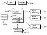
- FIG. 1is a simplified block diagram of an electronic hand-held device, according to the present invention.
- FIG. 2is a top plan view of an electronic hand-held device, according to the present invention.
- FIG. 3is a graph illustrating the resonance frequency, according to the present invention.
- FIG. 4is a side view of a parallel type mass-loaded piezo-bender, according to a preferred embodiment of the present invention.
- FIG. 1is an electrical block diagram of an electronic hand-held device, e.g. a Personal Digital Assistant (PDA) or a mobile phone.
- PDAPersonal Digital Assistant
- FIG. 1does not comprise all of the elements required in the electronic hand-held device but only the relevant elements in accordance with the present invention.
- the electronic hand-held devicecomprises a central processing unit CPU for controlling the electronic hand-held device.
- a memory MEMis associated with the CPU to store relevant software applications and other relevant information.
- the electronic hand-held devicecomprises at least a partially transparent lens TP which covers at least the display; the term touch panel may also be used when referring to the lens.
- the actual display DSPis located under the transparent lens TP area.
- the lens TPis also used as a primary input device.
- User actionsare detected with means IM for detecting stimulus signals.
- Means IM for detectingin one embodiment refers preferably to force sensors PS attached directly or indirectly to the lens TP. With three force sensors any location (i.e. a touch) on the lens TP area can be recognised and a relevant procedure started.
- Means IM for detecting stimulus signals together with the lens TP and the display DSPmay refer to a conventional touch-sensitive display.
- means IM for detecting stimulus signalsmay refer to several different physical or software components with which the stimulus signal(s) can be detected.
- FIG. 1also comprises a drive circuit DC and vibrating element(s) VIB.
- the drive circuit (DC)is electrically coupled to the resonating vibrating element(s) (VIB) and electrically drives the resonating vibrating element(s) (VIB) with a drive signal, the drive signal being constituted based on the stimulus signal.
- a vibrating elementis preferably a piezo-electric element attached directly to the lens TP.
- the CPUcontrols the drive circuit DC which itself supplies a drive signal to the vibrating element(s) VIB.
- the piezo-electric elementis attached to the lens TP, e.g. by gluing, welding, screwing or any other attachment method, device or facility suitable or appropriate to the use and functionality herein disclosed.
- the CPUcomprises means DM for determining the source of the stimulus signal, means TM for determining the resonance frequency by producing a bursted frequency sweep, means LM for detecting the vibration level with the force sensors PS, and means OM for feeding the obtained frequency to the resonating vibrating element(s) VIB.
- means DMfor determining the source of the stimulus signal
- means TMfor determining the resonance frequency by producing a bursted frequency sweep
- means LMfor detecting the vibration level with the force sensors PS
- means OMfor feeding the obtained frequency to the resonating vibrating element(s) VIB.
- the drive circuit DCin one embodiment comprises several components. It can comprise, e.g. an analog to digital converter (A/D), a digital signal processor, a digital to analog converter (D/A) and an amplifier.
- A/Danalog to digital converter
- D/Adigital to analog converter
- an amplifiere.g. a radio signal is received with the radio receiver RF
- the radio signalis input to a digital signal processor.
- the digital signal processorprocesses the radio signal and inputs the signal to the D/A-converter.
- the analog signalis then amplified by the amplifier and, finally, the amplified signal is input to the piezo-bender. Because the piezo-bender is attached to the lens TP, the whole system acts like an audio speaker and is able to produce an audio signal.
- the vibrating elemente.g. a piezo-bender
- the means IMfor detecting the user stimulus signal. Therefore, both detecting the user stimulus signal and generating a feedback signal is produced by an integrated component.
- the piezo-benderis also used in measuring acceleration.
- the piezo-bendermeasures force changes (i.e. acceleration) resulting from the inertia.
- force changesi.e. acceleration
- the zooming factor of the material on the display of the hand-held devicecan depend on the measured acceleration information; this zooming example is described in more detail in patent application WO0127735 (Myorigo).
- the electronic hand-held deviceis a mobile phone and/or a radio
- the devicewill also comprise a radio receiver RF part for sending and receiving radio frequency signals.
- FIG. 2is a top plan view of an electronic hand-held device HD.
- the deviceis preferably a Personal Digital Assistant (PDA) or a mobile phone.
- FIG. 2is a simplified example of an electronic hand-held device, so the device may additionally comprise other features and/or functional buttons.
- the electronic hand-held device HD of FIG. 2comprises a housing HS that has a partially transparent lens TP covering the actual display DSP.
- the lens/touch panel TPitself is not touch-sensitive.
- Force sensors PSare directly or indirectly attached to the lens TP. In the device depicted in FIG. 2 , there are three force sensors PS attached to the lens TP.
- the force sensors PSare in a preferred embodiment attached to the housing HS, as in a triangular form.
- the force sensors PScan be attached in any other appropriate way.
- the lens TPitself does not have to contain any touch-sensitive membrane or any other touch-sensitive features. Instead, a touch is detected with the force sensors PS.
- the force sensorscan also sense a user input outside of the transparent lens area. Therefore, certain areas of the housing HS or non-transparent areas of the lens TP can also be used as a part of the user interface.
- the device shown in FIG. 2additionally includes a resonating vibrating element VIB.
- the resonating vibrating element VIBis attached to an area of the lens TP not covering the display DSP.
- the lens TPis preferably impervious outside the display DSP area.
- the vibrating element VIBis preferably a piezo-electric element and may be of unimorph, bimorph or multilayer structure; a multilayer structure is the preferred solution because of the low input voltage required.
- the piezo-benderis preferably formed of three parts: an upper part, a lower part and a metal element between those parts. The metal element significantly strengthens the overall structure.
- the drive circuit DC of FIG. 1applies the desired drive signal to the resonating vibrating element VIB, thus causing the vibrating element VIB to vibrate/resonate at a certain frequency.
- the resonating vibrating elementsare used to provide multiple feedback signals.
- the resonating vibrating elementis preferably a piezo-bender of unimorph, bimorph or multilayer structure.
- the stimulus signalcan originate from different sources.
- the stimulus signalcan be a user-actuated signal, e.g. a touch on the lens. It can also be a radio frequency signal received via the radio receiver of the electronic device; this is the case where the electronic device is, e.g., a mobile phone.
- the stimulus signalcan be an electronic device induced signal, e.g. an operating system originated signal. Therefore, each stimulus signal may cause a different feedback signal.
- a pulsed or continuous haptic feedback signalis generated.
- the haptic feedback signalis typically a short signal, e.g. a frequency of 200-300 Hz and a duration of 5-100, or a continuous signal.
- This signalis typically a plain or modulated resonance frequency of the piezo-bender.
- the feedback signaldoes not have to be restricted only to haptic feedback. With a piezo-bender, practically any required or desired frequency bandwidth can be produced.
- the feedback signalcan additionally be a buzzer signal, a vibratory alert signal or an audio signal.
- a piezo-bender attached to the lens of the electronic hand-held devicecan act as a speaker.
- Production of an audio signalmay require that the audio bandwidth is flattened by digital signal processing in order to reduce the effect of the cantilever resonance frequencies. Certain criteria must be satisfied when generating audio signals. Especially in implementing the buzzer feature, the sound pressure level (in Pascals) has to be adequate, and the frequency band must be sufficiently broad. In addition, the harmonic multifold frequencies of the resonance frequency can be utilized when generating the feedback signal.
- a conventional electronic devicecomprises different components for generating a haptic feedback signal, a buzzer signal, a vibratory alert signal or an audio signal.
- a buzzer signalis generated with a buzzer
- an audio signalis generated, e.g. with a speaker
- a vibratory alert signalis generated, e.g. with an electromagnetic motor
- a haptic feedback signalis generated, e.g. with a DC motor, a solenoid, a moving magnet actuator, etc.
- All such feedback signalscan in accordance with the present invention be generated with a piezo-element. This means a significant decrement in power consumption as compared to a situation in which the various feedback signals are generated with separate components.
- FIGS. 1 and 2represent only one embodiment of the dynamic user interface described in the present invention.
- the dynamic user interfaceis not, however, restricted to any special devices.
- the dynamic user interfaceis able to generate user detectable multi-functional feedback with a single component in response to a stimulus signal.
- the stimulus signalcan be a user actuated signal, a radio signal received with a radio receiver or a device induced signal.
- the user interfacecomprises at least a housing and electronic circuitry located in the housing. The shape of the housing is not restricted. With means for detecting the stimulus signal a stimulus signal source is defined.
- One or more resonating vibrating elementsis attached to the housing or on the electronic circuitry, e.g. a PCB board located in the housing.
- An electrical drive circuitelectrically coupled to the resonating vibrating element(s) electrically drives the resonating vibrating element(s) with a drive signal, the drive signal being constituted based on the stimulus signal.
- the resonating vibrating elementis preferably a piezo-bender of unimorph, bimorph or multilayer structure. It is crucial to define the type of the stimulus signal because the feedback signal generated by the piezo-bender solely depends on the stimulus signal.
- the feedback signalis a haptic feedback signal, a vibratory alert signal, an audio signal or a buzzer signal. It is also important to carefully define the attachment point of the piezo-bender to the housing or to the electronic circuitry.
- the piezo-bender componentitself does not produce all of the needed feedback signals but, attached to the housing or to the electronic circuitry, it is able to produce multi-functional feedback.
- Such devicesinclude, by way of illustrative example, joysticks, keyboards, e-books, or practically any device in which multi-functional feedback can be employed.
- FIG. 3depicts the acceleration and the current-frequency response of an exemplary electronic hand-held device.
- the upper graphrepresents the acceleration factor of the lens as a function of frequency; the larger the acceleration value, the stronger the feedback to the user.
- the lower graphrepresents the current as a function of frequency.
- an external massis attached to the vibrating element. The use of an external mass increases the force obtained at the clamp point of the piezo-bender and also improves the low-frequency audio bandwidth.
- the reason that the frequency range for haptic feedback is quite low, e.g. 200-300 Hz,is that normally a human being is not particularly sensitive to higher frequencies, such as through or with an individual's hand.
- the peak current valueis slightly higher at resonance than in the frequencies immediately surrounding the resonance frequency.
- the acceleration and the current values shown in FIG. 3are not necessarily real values, but are merely illustrative or exemplary.
- the resonance frequencycan utilized in yet another way.
- the lens or the overall housingmay be manufactured such that one of the resonance frequencies of the lens or of the housing is in the same frequency range as that of the vibrating element. In this manner the overall effect of the haptic feedback is rendered more efficient.
- the electronic hand-held devicecomprises a feature by which the optimal frequency may be determined. This is done by determining the resonance frequency by producing a burst frequency sweep.
- the force sensorscan be made use of in another situation.
- the haptic feedback responses of the vibrating element(s)can be detected with the force sensors. Using the force sensors it is possible to determine the individual resonance frequency.
- the drive circuitis set to feed the obtained frequency to the vibrating element(s).
- the feedback parameterscan also be individually tuned for each person using the device.
- the main parameters that the user can controlare, for example, the amplitude, the time period of the vibration, and the vibration frequency.
- FIG. 4is a side view of a parallel type mass-loaded piezo-bender in accordance with a preferred embodiment of the present invention.
- the metal beam 42is placed between the piezo-ceramic layers 41 and 43 .
- the metal beam 42extends beyond the piezo-ceramic layers 41 and 43 and has a mass 44 mechanically coupled to the extended end of the metal beam 42 .
- the mass 44may be spot welded to the metal beam 42 , and provides a vibratable body at one end of the cantilever structure.
- the other end of the piezo-benderis clamped to the lens or housing 45 .
- an electrical driving signalis applied, for example across the opposing surfaces of the piezo layers, the tip of the piezo-bender begins to deflect.
- the deflections at the resonance frequency of the piezo-benderare significantly greater than without the mass because of the extension of metal beam 42 beyond the piezo-ceramic layers 41 , 43 and because of the mass 44 at the end of beam 42 .
- the vibrating mass 44 ′ and vibrating bendertend to impart greater impulses to the lens or housing 45 through each vibration cycle.
- the resonating vibrating elements utilized in implementing several different functionswhereas in prior-art solutions each function requires a dedicated component. Therefore, valuable space savings are realized in electronic hand-held devices and, above all, power consumption is minimized. This is a very important and advantageous feature in electronic hand-held devices.
- the present inventionadditionally provides a solution using only a single component to generate feedback, resulting in significant space savings on the Printed Circuit Board (PCB) since the number of components needed on the PCB is reduced.
- PCBPrinted Circuit Board
- the present inventionalso presents a low-cost solution because of the savings in the components.
- the feedbackcan be electrically adjusted.
- a desired feedbackcan be achieved.
- the adjustmentcan be set manually by the user or automatically by the device itself.
- the present inventionfurthermore provides a dynamic user interface and an integrated low-cost and low-power solution for producing multi-functional feedback.
- the piezo-bender componentis not itself necessarily able to generate all of the feedback signals (i.e. a haptic feedback signal, a buzzer signal, a vibratory alert signal, and an audio signal) described herein in accordance with the present invention.
- the situationis different when the piezo-bender is attached to another component, as for example to a lens, or to a certain part of a housing, or to a PCB board. Together with the component to or on which the piezo-bender is attached, multi-functional feedback can be generated as herein described.
Landscapes
- Engineering & Computer Science (AREA)
- Theoretical Computer Science (AREA)
- General Engineering & Computer Science (AREA)
- Human Computer Interaction (AREA)
- Physics & Mathematics (AREA)
- General Physics & Mathematics (AREA)
- Computer Hardware Design (AREA)
- User Interface Of Digital Computer (AREA)
- Apparatuses For Generation Of Mechanical Vibrations (AREA)
- Position Input By Displaying (AREA)
- Telephone Function (AREA)
Abstract
Description
Claims (16)
Applications Claiming Priority (3)
| Application Number | Priority Date | Filing Date | Title |
|---|---|---|---|
| FI20012187AFI115861B (en) | 2001-11-12 | 2001-11-12 | Method and apparatus for generating a response |
| FI20012187 | 2001-11-12 | ||
| PCT/FI2002/000889WO2003042805A1 (en) | 2001-11-12 | 2002-11-11 | Method and device for generating feedback |
Related Parent Applications (1)
| Application Number | Title | Priority Date | Filing Date |
|---|---|---|---|
| PCT/FI2002/000889ContinuationWO2003042805A1 (en) | 2001-11-12 | 2002-11-11 | Method and device for generating feedback |
Publications (2)
| Publication Number | Publication Date |
|---|---|
| US20040227721A1 US20040227721A1 (en) | 2004-11-18 |
| US7324094B2true US7324094B2 (en) | 2008-01-29 |
Family
ID=8562231
Family Applications (1)
| Application Number | Title | Priority Date | Filing Date |
|---|---|---|---|
| US10/840,174Expired - LifetimeUS7324094B2 (en) | 2001-11-12 | 2004-05-05 | Method and device for generating multi-functional feedback |
Country Status (9)
| Country | Link |
|---|---|
| US (1) | US7324094B2 (en) |
| EP (1) | EP1449058B1 (en) |
| JP (1) | JP4568498B2 (en) |
| KR (1) | KR100621706B1 (en) |
| CN (1) | CN1284070C (en) |
| CA (1) | CA2465834C (en) |
| FI (1) | FI115861B (en) |
| RU (1) | RU2285945C9 (en) |
| WO (1) | WO2003042805A1 (en) |
Cited By (58)
| Publication number | Priority date | Publication date | Assignee | Title |
|---|---|---|---|---|
| US20070035526A1 (en)* | 2005-07-29 | 2007-02-15 | Mikio Takenaka | Touch panel display apparatus, electronic device having touch panel display apparatus, and camera having touch panel display apparatus |
| US20070072665A1 (en)* | 2001-09-28 | 2007-03-29 | Igt, A Nevada Corporation | Methods, Apparatuses And Systems for Multilayer Gaming |
| US20070243928A1 (en)* | 2006-04-13 | 2007-10-18 | Igt | Casino gaming incentives using game themes, game types, paytables, denominations |
| US20080064497A1 (en)* | 2004-01-12 | 2008-03-13 | Igt | Method and apparatus for using a light valve to reduce the visibility of an object within a gaming apparatus |
| US20080113747A1 (en)* | 2006-11-13 | 2008-05-15 | Igt | Mechanical reel hardware simulation using multiple layer displays |
| US20080113749A1 (en)* | 2006-11-13 | 2008-05-15 | Igt | Multimedia emulation of physical reel hardware in processor-based gaming machines |
| US20080113746A1 (en)* | 2006-11-13 | 2008-05-15 | Igt | Realistic video reels |
| US20080113748A1 (en)* | 2006-11-13 | 2008-05-15 | Igt | Simulated reel imperfections |
| US20080136741A1 (en)* | 2006-11-13 | 2008-06-12 | Igt | Single plane spanning mode across independently driven displays |
| US20090036208A1 (en)* | 2002-08-06 | 2009-02-05 | Igt | Reel and video combination machine |
| DE202009004561U1 (en) | 2009-04-02 | 2009-06-25 | Pi Ceramic Gmbh Keramische Technologien Und Bauelemente | Device for generating a haptic feedback of a keyless input unit |
| US20090231272A1 (en)* | 2008-03-13 | 2009-09-17 | International Business Machines Corporation | Virtual hand: a new 3-d haptic interface and system for virtual environments |
| US20090231287A1 (en)* | 2008-03-13 | 2009-09-17 | International Business Machines Corporation | Novel tactile input/output device and system to represent and manipulate computer-generated surfaces |
| US20090243997A1 (en)* | 2008-03-27 | 2009-10-01 | Immersion Corporation | Systems and Methods For Resonance Detection |
| US20090313542A1 (en)* | 2008-06-12 | 2009-12-17 | Immersion Corporation | User Interface Impact Actuator |
| US20100156809A1 (en)* | 2008-12-19 | 2010-06-24 | Honeywell International Inc. | Method and apparatus for avionic touchscreen operation providing sensible feedback |
| US20100171715A1 (en)* | 2009-01-08 | 2010-07-08 | Cody George Peterson | Tactile Surface |
| WO2010112198A2 (en) | 2009-04-02 | 2010-10-07 | Pi Ceramic Gmbh | Device for creating a haptic feedback of a keyless input unit |
| US7841944B2 (en) | 2002-08-06 | 2010-11-30 | Igt | Gaming device having a three dimensional display device |
| US20100328242A1 (en)* | 2009-06-24 | 2010-12-30 | Research In Motion Limited | Piezoelectric assembly |
| US20110012717A1 (en)* | 2009-07-17 | 2011-01-20 | Apple Inc. | Method and apparatus for localization of haptic feedback |
| US20110074559A1 (en)* | 2009-09-29 | 2011-03-31 | Visteon Global Technologies, Inc. | Mounting Apparatus For A Haptic Surface |
| US20110074560A1 (en)* | 2009-09-29 | 2011-03-31 | Visteon Global Technologies, Inc. | Haptic Surface With Mechanical Buttons |
| US20110234494A1 (en)* | 2009-10-15 | 2011-09-29 | Cody Peterson | Support-Surface Apparatus to Impart Tactile Feedback |
| US8142273B2 (en) | 2006-11-13 | 2012-03-27 | Igt | Presentation of wheels on gaming machines having multi-layer displays |
| US8210922B2 (en) | 2006-11-13 | 2012-07-03 | Igt | Separable game graphics on a gaming machine |
| US8298081B1 (en) | 2011-06-16 | 2012-10-30 | Igt | Gaming system, gaming device and method for providing multiple display event indicators |
| US8309870B2 (en) | 2011-01-04 | 2012-11-13 | Cody George Peterson | Leveled touchsurface with planar translational responsiveness to vertical travel |
| US8425316B2 (en) | 2010-08-03 | 2013-04-23 | Igt | Methods and systems for improving play of a bonus game on a gaming machine and improving security within a gaming establishment |
| US8605114B2 (en) | 2012-02-17 | 2013-12-10 | Igt | Gaming system having reduced appearance of parallax artifacts on display devices including multiple display screens |
| US8659210B2 (en) | 2010-11-02 | 2014-02-25 | Immersion Corporation | Piezo based inertia actuator for high definition haptic feedback |
| US8735755B2 (en) | 2011-03-07 | 2014-05-27 | Synaptics Incorporated | Capacitive keyswitch technologies |
| US8847890B2 (en) | 2011-01-04 | 2014-09-30 | Synaptics Incorporated | Leveled touchsurface with planar translational responsiveness to vertical travel |
| US8912458B2 (en) | 2011-01-04 | 2014-12-16 | Synaptics Incorporated | Touchsurface with level and planar translational travel responsiveness |
| US8947372B2 (en) | 2010-08-11 | 2015-02-03 | Blackberry Limited | Electronic device including touch-sensitive display |
| US9032818B2 (en) | 2012-07-05 | 2015-05-19 | Nextinput, Inc. | Microelectromechanical load sensor and methods of manufacturing the same |
| US9040851B2 (en) | 2012-08-06 | 2015-05-26 | Synaptics Incorporated | Keycap assembly with an interactive spring mechanism |
| US9177733B2 (en) | 2012-08-06 | 2015-11-03 | Synaptics Incorporated | Touchsurface assemblies with linkages |
| US9213372B2 (en) | 2013-04-19 | 2015-12-15 | Synaptics Incorporated | Retractable keyboard keys |
| US9218927B2 (en) | 2012-08-06 | 2015-12-22 | Synaptics Incorporated | Touchsurface assembly with level and planar translational responsiveness via a buckling elastic component |
| US9224554B2 (en) | 2013-03-14 | 2015-12-29 | Synaptics Incorporated | Anti-tilt and rotation techniques for a touchsurface assembly having translating keys |
| US9324515B2 (en) | 2012-08-06 | 2016-04-26 | Synaptics Incorporated | Touchsurface assembly utilizing magnetically enabled hinge |
| US9349552B2 (en) | 2010-05-24 | 2016-05-24 | Synaptics Incorporated | Touchpad with capacitive force sensing |
| US9487388B2 (en) | 2012-06-21 | 2016-11-08 | Nextinput, Inc. | Ruggedized MEMS force die |
| US9902611B2 (en) | 2014-01-13 | 2018-02-27 | Nextinput, Inc. | Miniaturized and ruggedized wafer level MEMs force sensors |
| US10466119B2 (en) | 2015-06-10 | 2019-11-05 | Nextinput, Inc. | Ruggedized wafer level MEMS force sensor with a tolerance trench |
| US10962427B2 (en) | 2019-01-10 | 2021-03-30 | Nextinput, Inc. | Slotted MEMS force sensor |
| US10959674B2 (en) | 2017-10-23 | 2021-03-30 | Datafeel Inc. | Communication devices, methods, and systems |
| US11221263B2 (en) | 2017-07-19 | 2022-01-11 | Nextinput, Inc. | Microelectromechanical force sensor having a strain transfer layer arranged on the sensor die |
| US11243125B2 (en) | 2017-02-09 | 2022-02-08 | Nextinput, Inc. | Integrated piezoresistive and piezoelectric fusion force sensor |
| US11243126B2 (en) | 2017-07-27 | 2022-02-08 | Nextinput, Inc. | Wafer bonded piezoresistive and piezoelectric force sensor and related methods of manufacture |
| US11255737B2 (en) | 2017-02-09 | 2022-02-22 | Nextinput, Inc. | Integrated digital force sensors and related methods of manufacture |
| US11383272B2 (en) | 2016-09-07 | 2022-07-12 | Tdk Electronics Ag | Apparatus for producing haptic feedback and electronic device |
| US11385108B2 (en) | 2017-11-02 | 2022-07-12 | Nextinput, Inc. | Sealed force sensor with etch stop layer |
| US11423686B2 (en) | 2017-07-25 | 2022-08-23 | Qorvo Us, Inc. | Integrated fingerprint and force sensor |
| US11579028B2 (en) | 2017-10-17 | 2023-02-14 | Nextinput, Inc. | Temperature coefficient of offset compensation for force sensor and strain gauge |
| US11874185B2 (en) | 2017-11-16 | 2024-01-16 | Nextinput, Inc. | Force attenuator for force sensor |
| US11934583B2 (en) | 2020-10-30 | 2024-03-19 | Datafeel Inc. | Wearable data communication apparatus, kits, methods, and systems |
Families Citing this family (53)
| Publication number | Priority date | Publication date | Assignee | Title |
|---|---|---|---|---|
| US7769417B2 (en)* | 2002-12-08 | 2010-08-03 | Immersion Corporation | Method and apparatus for providing haptic feedback to off-activating area |
| US7218313B2 (en)* | 2003-10-31 | 2007-05-15 | Zeetoo, Inc. | Human interface system |
| JP4543863B2 (en)* | 2004-10-05 | 2010-09-15 | ソニー株式会社 | Input/output devices and electronic devices with tactile functions |
| US20060097996A1 (en)* | 2004-11-10 | 2006-05-11 | Alps Electric Co., Ltd. | Input device |
| JP4539314B2 (en)* | 2004-12-03 | 2010-09-08 | 富士電機システムズ株式会社 | Alarm unit |
| KR100615554B1 (en)* | 2005-01-25 | 2006-08-25 | 한국정보통신대학교 산학협력단 | Tactile information input system and device for micro information equipment |
| JP2006334541A (en)* | 2005-06-03 | 2006-12-14 | Sony Corp | Electric machine converter, electric machine conversion method, and electronic device using the same |
| EP1752860B1 (en)* | 2005-08-12 | 2015-03-18 | LG Electronics Inc. | Mobile terminal with touch screen providing haptic feedback and corresponding method |
| US7669770B2 (en) | 2005-09-06 | 2010-03-02 | Zeemote, Inc. | Method of remapping the input elements of a hand-held device |
| US7652660B2 (en) | 2005-10-11 | 2010-01-26 | Fish & Richardson P.C. | Mobile device customizer |
| US7649522B2 (en) | 2005-10-11 | 2010-01-19 | Fish & Richardson P.C. | Human interface input acceleration system |
| US7280097B2 (en) | 2005-10-11 | 2007-10-09 | Zeetoo, Inc. | Human interface input acceleration system |
| US8510666B2 (en) | 2006-03-14 | 2013-08-13 | Siemens Enterprise Communications Gmbh & Co. Kg | Systems for development and/or use of telephone user interface |
| JP4697095B2 (en)* | 2006-08-29 | 2011-06-08 | ソニー株式会社 | Touch panel display device, electronic device and game device |
| KR20080058121A (en)* | 2006-12-21 | 2008-06-25 | 삼성전자주식회사 | Apparatus and method for providing a tactile user interface in a mobile terminal |
| EP1939062B1 (en)* | 2006-12-28 | 2011-03-09 | Magneti Marelli S.p.A. | A tactile/acoustic signaling arrangement for warning the driver of a vehicle, as well as a vehicle steering device and driving assistance system including such an arrangement |
| US20080259046A1 (en)* | 2007-04-05 | 2008-10-23 | Joseph Carsanaro | Pressure sensitive touch pad with virtual programmable buttons for launching utility applications |
| JP4838280B2 (en)* | 2008-03-31 | 2011-12-14 | 太平洋セメント株式会社 | Touch panel type input device |
| WO2010009149A2 (en)* | 2008-07-15 | 2010-01-21 | Immersion Corporation | Systems and methods for transmitting haptic messages |
| US8106787B2 (en)* | 2008-11-14 | 2012-01-31 | Nokia Corporation | Warning system indicating excessive force on a touch screen or display |
| CN102265246B (en)* | 2008-12-22 | 2015-05-27 | 京瓷株式会社 | input device |
| US20100156814A1 (en)* | 2008-12-23 | 2010-06-24 | Research In Motion Limited | Portable electronic device including tactile touch-sensitive input device and method of controlling same |
| JP2010157037A (en)* | 2008-12-26 | 2010-07-15 | Nissha Printing Co Ltd | Panel member having oscillating element |
| WO2010118313A1 (en)* | 2009-04-10 | 2010-10-14 | Immerz Inc. | Systems and methods for acousto-haptic speakers |
| US10401961B2 (en) | 2009-06-09 | 2019-09-03 | Immersion Corporation | Method and apparatus for generating haptic effects using actuators |
| US9891708B2 (en)* | 2009-06-09 | 2018-02-13 | Immersion Corporation | Method and apparatus for generating haptic effects using actuators |
| JP5306944B2 (en)* | 2009-08-31 | 2013-10-02 | 日本写真印刷株式会社 | Mounting structure of speaker touch panel |
| JP5306945B2 (en)* | 2009-08-31 | 2013-10-02 | 日本写真印刷株式会社 | Mounting structure of tactile feedback type touch panel |
| FR2958424B1 (en)* | 2010-04-02 | 2015-05-15 | Thales Sa | HAPTIC INTERACTION DEVICE. |
| KR101053356B1 (en)* | 2010-05-12 | 2011-08-01 | 삼성전기주식회사 | Haptic Feedback Devices and Electronics |
| FR2961610B1 (en)* | 2010-06-18 | 2013-01-18 | Thales Sa | HOSPITABLE INTERACTION DEVICE ENHANCED BY THE EFFORT |
| JP5815698B2 (en)* | 2010-07-16 | 2015-11-17 | コーニンクレッカ フィリップス エヌ ヴェKoninklijke Philips N.V. | Device comprising a multi-actuator haptic surface that produces a haptic effect on the haptic surface |
| US10645834B2 (en) | 2010-08-23 | 2020-05-05 | Nokia Technologies Oy | Apparatus and method for providing haptic and audio feedback in a touch sensitive user interface |
| JP5591095B2 (en)* | 2010-12-20 | 2014-09-17 | トヨタ自動車株式会社 | Tactile display |
| JP5903797B2 (en)* | 2011-08-15 | 2016-04-13 | 富士通株式会社 | Portable terminal device and control method |
| US9582178B2 (en) | 2011-11-07 | 2017-02-28 | Immersion Corporation | Systems and methods for multi-pressure interaction on touch-sensitive surfaces |
| US8890666B2 (en)* | 2011-11-21 | 2014-11-18 | Immersion Corporation | Piezoelectric actuator for haptic device |
| ITMI20121803A1 (en)* | 2012-10-24 | 2014-04-25 | Altergon Sa | METHOD AND MEASUREMENT AND CONTROL DEVICE FOR THE DOSAGE OF SMALL QUANTITIES OF FLUID BY MEANS OF NEEDLE RESONANT, AND NEEDLE RESONANT SUITABLE FOR THE PURPOSE |
| US20140232679A1 (en)* | 2013-02-17 | 2014-08-21 | Microsoft Corporation | Systems and methods to protect against inadvertant actuation of virtual buttons on touch surfaces |
| US10578499B2 (en)* | 2013-02-17 | 2020-03-03 | Microsoft Technology Licensing, Llc | Piezo-actuated virtual buttons for touch surfaces |
| US9448631B2 (en) | 2013-12-31 | 2016-09-20 | Microsoft Technology Licensing, Llc | Input device haptics and pressure sensing |
| KR101715926B1 (en)* | 2014-05-14 | 2017-03-14 | 주식회사 엠플러스 | Vibrator and electronic device including the same |
| US10222889B2 (en) | 2015-06-03 | 2019-03-05 | Microsoft Technology Licensing, Llc | Force inputs and cursor control |
| US10416799B2 (en) | 2015-06-03 | 2019-09-17 | Microsoft Technology Licensing, Llc | Force sensing and inadvertent input control of an input device |
| US10248207B2 (en) | 2015-10-28 | 2019-04-02 | Capital One Services, Llc | Systems and methods for providing variable haptic feedback |
| KR101877503B1 (en)* | 2015-12-24 | 2018-07-11 | 주식회사 모다이노칩 | Complex device and electronic device having the same |
| US10061385B2 (en) | 2016-01-22 | 2018-08-28 | Microsoft Technology Licensing, Llc | Haptic feedback for a touch input device |
| CN106980373B (en)* | 2017-03-29 | 2023-10-20 | 苏州攀特电陶科技股份有限公司 | Mobile terminal device, haptic feedback and audio control method and system |
| JP7055950B2 (en)* | 2018-02-28 | 2022-04-19 | 太陽誘電株式会社 | Vibration generators and electronic devices |
| WO2020023022A1 (en)* | 2018-07-24 | 2020-01-30 | Hewlett-Packard Development Company, L.P. | Device housing with metallic luster |
| US11812218B1 (en)* | 2018-10-12 | 2023-11-07 | Cirrus Logic Inc. | Concurrent audio and haptics from a single mechanical transducer |
| KR102718381B1 (en)* | 2019-04-01 | 2024-10-16 | 삼성디스플레이 주식회사 | Display device and method for driving the same |
| US11429155B2 (en) | 2019-10-01 | 2022-08-30 | Dell Products L.P. | Information handling system including dynamic configuration of piezoelectric transducers for multi-functionality |
Citations (22)
| Publication number | Priority date | Publication date | Assignee | Title |
|---|---|---|---|---|
| JPS61138035A (en) | 1984-12-10 | 1986-06-25 | Toofure Kk | Generating and increasing method of infrared rays |
| US4885565A (en) | 1988-06-01 | 1989-12-05 | General Motors Corporation | Touchscreen CRT with tactile feedback |
| JPH02105919A (en) | 1988-10-14 | 1990-04-18 | Canon Inc | touch panel input device |
| WO1992000559A1 (en) | 1990-06-25 | 1992-01-09 | Hewlett-Packard Company | Input device with tactile feedback |
| JPH04137419A (en) | 1990-09-28 | 1992-05-12 | Ricoh Denshi Co Ltd | Touch panel |
| US5241308A (en) | 1990-02-22 | 1993-08-31 | Paragon Systems, Inc. | Force sensitive touch panel |
| US5245245A (en) | 1992-05-04 | 1993-09-14 | Motorola, Inc. | Mass-loaded cantilever vibrator |
| DE4323863A1 (en) | 1993-07-16 | 1995-01-19 | Andromeda Ges Fuer Computer Un | Tactile information communication to the user of hand-held computers |
| US5436622A (en)* | 1993-07-06 | 1995-07-25 | Motorola, Inc. | Variable frequency vibratory alert method and structure |
| JPH09161602A (en) | 1995-12-04 | 1997-06-20 | Idec Izumi Corp | Thin switch and display panel with switch |
| WO1997031333A1 (en) | 1996-02-23 | 1997-08-28 | Shalit Tomer | Display arrangement and method |
| JPH11162277A (en) | 1997-11-27 | 1999-06-18 | Omron Corp | Touch type input device, portable electronic equipment, remote control device and key input device |
| WO1999066997A1 (en) | 1998-06-23 | 1999-12-29 | Immersion Corporation | Low cost force feedback devices |
| JP2000137576A (en) | 1998-10-30 | 2000-05-16 | Nec Corp | Touch panel type input device |
| US6118435A (en)* | 1997-04-10 | 2000-09-12 | Idec Izumi Corporation | Display unit with touch panel |
| WO2001027735A1 (en) | 1999-10-12 | 2001-04-19 | Myorigo Oy | Operation method of user interface of hand-held device |
| JP2001117715A (en) | 1999-10-15 | 2001-04-27 | Fuji Xerox Co Ltd | Touch sense/force sense presentation device and information input/output device |
| WO2001052029A2 (en) | 2000-01-14 | 2001-07-19 | Sony Computer Entertainment Inc. | Method, recording medium, computer and controller for changing the settings of various parameters of electronic equipment |
| WO2001054109A1 (en) | 2000-01-19 | 2001-07-26 | Immersion Corporation | Haptic feedback for touchpads and other touch controls |
| US20020033795A1 (en) | 2000-01-19 | 2002-03-21 | Shahoian Erik J. | Haptic interface for laptop computers and other portable devices |
| US7039866B1 (en)* | 1995-12-01 | 2006-05-02 | Immersion Corporation | Method and apparatus for providing dynamic force sensations for force feedback computer applications |
| US7131073B2 (en)* | 1995-12-13 | 2006-10-31 | Immersion Corporation | Force feedback applications based on cursor engagement with graphical targets |
Family Cites Families (1)
| Publication number | Priority date | Publication date | Assignee | Title |
|---|---|---|---|---|
| US5797089A (en)* | 1995-09-07 | 1998-08-18 | Telefonaktiebolaget Lm Ericsson (Publ) | Personal communications terminal having switches which independently energize a mobile telephone and a personal digital assistant |
- 2001
- 2001-11-12FIFI20012187Apatent/FI115861B/ennot_activeIP Right Cessation
- 2002
- 2002-11-11EPEP20020777375patent/EP1449058B1/ennot_activeExpired - Lifetime
- 2002-11-11CNCNB02822440XApatent/CN1284070C/ennot_activeExpired - Lifetime
- 2002-11-11RURU2004114257/09Apatent/RU2285945C9/ennot_activeIP Right Cessation
- 2002-11-11WOPCT/FI2002/000889patent/WO2003042805A1/enactiveApplication Filing
- 2002-11-11KRKR1020047007164Apatent/KR100621706B1/ennot_activeExpired - Fee Related
- 2002-11-11CACA002465834Apatent/CA2465834C/ennot_activeExpired - Fee Related
- 2002-11-11JPJP2003544572Apatent/JP4568498B2/ennot_activeExpired - Fee Related
- 2004
- 2004-05-05USUS10/840,174patent/US7324094B2/ennot_activeExpired - Lifetime
Patent Citations (23)
| Publication number | Priority date | Publication date | Assignee | Title |
|---|---|---|---|---|
| JPS61138035A (en) | 1984-12-10 | 1986-06-25 | Toofure Kk | Generating and increasing method of infrared rays |
| US4885565A (en) | 1988-06-01 | 1989-12-05 | General Motors Corporation | Touchscreen CRT with tactile feedback |
| JPH02105919A (en) | 1988-10-14 | 1990-04-18 | Canon Inc | touch panel input device |
| US5241308A (en) | 1990-02-22 | 1993-08-31 | Paragon Systems, Inc. | Force sensitive touch panel |
| WO1992000559A1 (en) | 1990-06-25 | 1992-01-09 | Hewlett-Packard Company | Input device with tactile feedback |
| JPH04137419A (en) | 1990-09-28 | 1992-05-12 | Ricoh Denshi Co Ltd | Touch panel |
| US5245245A (en) | 1992-05-04 | 1993-09-14 | Motorola, Inc. | Mass-loaded cantilever vibrator |
| US5436622A (en)* | 1993-07-06 | 1995-07-25 | Motorola, Inc. | Variable frequency vibratory alert method and structure |
| DE4323863A1 (en) | 1993-07-16 | 1995-01-19 | Andromeda Ges Fuer Computer Un | Tactile information communication to the user of hand-held computers |
| US7039866B1 (en)* | 1995-12-01 | 2006-05-02 | Immersion Corporation | Method and apparatus for providing dynamic force sensations for force feedback computer applications |
| JPH09161602A (en) | 1995-12-04 | 1997-06-20 | Idec Izumi Corp | Thin switch and display panel with switch |
| US7131073B2 (en)* | 1995-12-13 | 2006-10-31 | Immersion Corporation | Force feedback applications based on cursor engagement with graphical targets |
| WO1997031333A1 (en) | 1996-02-23 | 1997-08-28 | Shalit Tomer | Display arrangement and method |
| US6118435A (en)* | 1997-04-10 | 2000-09-12 | Idec Izumi Corporation | Display unit with touch panel |
| JPH11162277A (en) | 1997-11-27 | 1999-06-18 | Omron Corp | Touch type input device, portable electronic equipment, remote control device and key input device |
| US6429846B2 (en)* | 1998-06-23 | 2002-08-06 | Immersion Corporation | Haptic feedback for touchpads and other touch controls |
| WO1999066997A1 (en) | 1998-06-23 | 1999-12-29 | Immersion Corporation | Low cost force feedback devices |
| JP2000137576A (en) | 1998-10-30 | 2000-05-16 | Nec Corp | Touch panel type input device |
| WO2001027735A1 (en) | 1999-10-12 | 2001-04-19 | Myorigo Oy | Operation method of user interface of hand-held device |
| JP2001117715A (en) | 1999-10-15 | 2001-04-27 | Fuji Xerox Co Ltd | Touch sense/force sense presentation device and information input/output device |
| WO2001052029A2 (en) | 2000-01-14 | 2001-07-19 | Sony Computer Entertainment Inc. | Method, recording medium, computer and controller for changing the settings of various parameters of electronic equipment |
| WO2001054109A1 (en) | 2000-01-19 | 2001-07-26 | Immersion Corporation | Haptic feedback for touchpads and other touch controls |
| US20020033795A1 (en) | 2000-01-19 | 2002-03-21 | Shahoian Erik J. | Haptic interface for laptop computers and other portable devices |
Cited By (115)
| Publication number | Priority date | Publication date | Assignee | Title |
|---|---|---|---|---|
| US20070072665A1 (en)* | 2001-09-28 | 2007-03-29 | Igt, A Nevada Corporation | Methods, Apparatuses And Systems for Multilayer Gaming |
| US20090036208A1 (en)* | 2002-08-06 | 2009-02-05 | Igt | Reel and video combination machine |
| US8715058B2 (en) | 2002-08-06 | 2014-05-06 | Igt | Reel and video combination machine |
| US7951001B2 (en) | 2002-08-06 | 2011-05-31 | Igt | Gaming device having a three dimensional display device |
| US7841944B2 (en) | 2002-08-06 | 2010-11-30 | Igt | Gaming device having a three dimensional display device |
| US8118670B2 (en) | 2004-01-12 | 2012-02-21 | Igt | Method and apparatus for using a light valve to reduce the visibility of an object within a gaming apparatus |
| US20080064497A1 (en)* | 2004-01-12 | 2008-03-13 | Igt | Method and apparatus for using a light valve to reduce the visibility of an object within a gaming apparatus |
| US8310452B2 (en)* | 2005-07-29 | 2012-11-13 | Sony Corporation | Touch panel display apparatus, electronic device having touch panel display apparatus, and camera having touch panel display apparatus |
| US20070035526A1 (en)* | 2005-07-29 | 2007-02-15 | Mikio Takenaka | Touch panel display apparatus, electronic device having touch panel display apparatus, and camera having touch panel display apparatus |
| US20070243928A1 (en)* | 2006-04-13 | 2007-10-18 | Igt | Casino gaming incentives using game themes, game types, paytables, denominations |
| US8199068B2 (en) | 2006-11-13 | 2012-06-12 | Igt | Single plane spanning mode across independently driven displays |
| US8357033B2 (en) | 2006-11-13 | 2013-01-22 | Igt | Realistic video reels |
| US20080113748A1 (en)* | 2006-11-13 | 2008-05-15 | Igt | Simulated reel imperfections |
| US20080113746A1 (en)* | 2006-11-13 | 2008-05-15 | Igt | Realistic video reels |
| US8360847B2 (en)* | 2006-11-13 | 2013-01-29 | Igt | Multimedia emulation of physical reel hardware in processor-based gaming machines |
| US20080113749A1 (en)* | 2006-11-13 | 2008-05-15 | Igt | Multimedia emulation of physical reel hardware in processor-based gaming machines |
| US8210922B2 (en) | 2006-11-13 | 2012-07-03 | Igt | Separable game graphics on a gaming machine |
| US8142273B2 (en) | 2006-11-13 | 2012-03-27 | Igt | Presentation of wheels on gaming machines having multi-layer displays |
| US20080136741A1 (en)* | 2006-11-13 | 2008-06-12 | Igt | Single plane spanning mode across independently driven displays |
| US20080113747A1 (en)* | 2006-11-13 | 2008-05-15 | Igt | Mechanical reel hardware simulation using multiple layer displays |
| US8192281B2 (en) | 2006-11-13 | 2012-06-05 | Igt | Simulated reel imperfections |
| AU2007323964B2 (en)* | 2006-11-13 | 2012-12-06 | Igt | Multimedia emulation of physical reel hardware in processor-based gaming machines |
| US8203529B2 (en) | 2008-03-13 | 2012-06-19 | International Business Machines Corporation | Tactile input/output device and system to represent and manipulate computer-generated surfaces |
| US8350843B2 (en) | 2008-03-13 | 2013-01-08 | International Business Machines Corporation | Virtual hand: a new 3-D haptic interface and system for virtual environments |
| US20090231272A1 (en)* | 2008-03-13 | 2009-09-17 | International Business Machines Corporation | Virtual hand: a new 3-d haptic interface and system for virtual environments |
| US20090231287A1 (en)* | 2008-03-13 | 2009-09-17 | International Business Machines Corporation | Novel tactile input/output device and system to represent and manipulate computer-generated surfaces |
| US20090243997A1 (en)* | 2008-03-27 | 2009-10-01 | Immersion Corporation | Systems and Methods For Resonance Detection |
| US8156809B2 (en) | 2008-03-27 | 2012-04-17 | Immersion Corporation | Systems and methods for resonance detection |
| US8590379B2 (en) | 2008-03-27 | 2013-11-26 | Immersion Corporation | Systems and methods for resonance detection |
| US9733704B2 (en)* | 2008-06-12 | 2017-08-15 | Immersion Corporation | User interface impact actuator |
| US10365720B2 (en)* | 2008-06-12 | 2019-07-30 | Immersion Corporation | User interface impact actuator |
| US20090313542A1 (en)* | 2008-06-12 | 2009-12-17 | Immersion Corporation | User Interface Impact Actuator |
| US8330732B2 (en) | 2008-12-19 | 2012-12-11 | Honeywell International Inc. | Method and apparatus for avionic touchscreen operation providing sensible feedback |
| US20100156809A1 (en)* | 2008-12-19 | 2010-06-24 | Honeywell International Inc. | Method and apparatus for avionic touchscreen operation providing sensible feedback |
| US8760413B2 (en) | 2009-01-08 | 2014-06-24 | Synaptics Incorporated | Tactile surface |
| US20110096013A1 (en)* | 2009-01-08 | 2011-04-28 | Krumpelman Douglas M | Techniques for tactile feedback technology |
| US20100171715A1 (en)* | 2009-01-08 | 2010-07-08 | Cody George Peterson | Tactile Surface |
| DE202009004561U1 (en) | 2009-04-02 | 2009-06-25 | Pi Ceramic Gmbh Keramische Technologien Und Bauelemente | Device for generating a haptic feedback of a keyless input unit |
| US8471690B2 (en) | 2009-04-02 | 2013-06-25 | Pi Ceramic Gmbh | Device for producing a haptic feedback from a keyless input unit |
| DE102009015991A1 (en) | 2009-04-02 | 2010-10-07 | Pi Ceramic Gmbh Keramische Technologien Und Bauelemente | Device for generating a haptic feedback of a keyless input unit |
| WO2010112198A2 (en) | 2009-04-02 | 2010-10-07 | Pi Ceramic Gmbh | Device for creating a haptic feedback of a keyless input unit |
| US8446076B2 (en) | 2009-06-24 | 2013-05-21 | Research In Motion Limited | Piezoelectric assembly |
| US20100328242A1 (en)* | 2009-06-24 | 2010-12-30 | Research In Motion Limited | Piezoelectric assembly |
| US8890668B2 (en)* | 2009-07-17 | 2014-11-18 | Apple Inc. | Method and apparatus for localization of haptic feedback |
| US20110012717A1 (en)* | 2009-07-17 | 2011-01-20 | Apple Inc. | Method and apparatus for localization of haptic feedback |
| US8378797B2 (en)* | 2009-07-17 | 2013-02-19 | Apple Inc. | Method and apparatus for localization of haptic feedback |
| US9395817B2 (en) | 2009-07-17 | 2016-07-19 | Apple Inc. | Method and apparatus for localization of haptic feedback |
| US20110074560A1 (en)* | 2009-09-29 | 2011-03-31 | Visteon Global Technologies, Inc. | Haptic Surface With Mechanical Buttons |
| US20110074559A1 (en)* | 2009-09-29 | 2011-03-31 | Visteon Global Technologies, Inc. | Mounting Apparatus For A Haptic Surface |
| US8310350B2 (en) | 2009-09-29 | 2012-11-13 | Visteon Global Technologies, Inc. | Mounting apparatus for a haptic surface |
| US8310349B2 (en) | 2009-09-29 | 2012-11-13 | Visteon Global Technologies, Inc. | Haptic surface with mechanical buttons |
| US8624839B2 (en) | 2009-10-15 | 2014-01-07 | Synaptics Incorporated | Support-surface apparatus to impart tactile feedback |
| US10068728B2 (en) | 2009-10-15 | 2018-09-04 | Synaptics Incorporated | Touchpad with capacitive force sensing |
| US20110234494A1 (en)* | 2009-10-15 | 2011-09-29 | Cody Peterson | Support-Surface Apparatus to Impart Tactile Feedback |
| US9349552B2 (en) | 2010-05-24 | 2016-05-24 | Synaptics Incorporated | Touchpad with capacitive force sensing |
| US8425316B2 (en) | 2010-08-03 | 2013-04-23 | Igt | Methods and systems for improving play of a bonus game on a gaming machine and improving security within a gaming establishment |
| US8947372B2 (en) | 2010-08-11 | 2015-02-03 | Blackberry Limited | Electronic device including touch-sensitive display |
| US8659210B2 (en) | 2010-11-02 | 2014-02-25 | Immersion Corporation | Piezo based inertia actuator for high definition haptic feedback |
| US8912458B2 (en) | 2011-01-04 | 2014-12-16 | Synaptics Incorporated | Touchsurface with level and planar translational travel responsiveness |
| US8309870B2 (en) | 2011-01-04 | 2012-11-13 | Cody George Peterson | Leveled touchsurface with planar translational responsiveness to vertical travel |
| US8847890B2 (en) | 2011-01-04 | 2014-09-30 | Synaptics Incorporated | Leveled touchsurface with planar translational responsiveness to vertical travel |
| US9430050B2 (en) | 2011-01-04 | 2016-08-30 | Synaptics Incorporated | Touchsurface with level and planar translational travel responsiveness |
| US8927890B2 (en) | 2011-03-07 | 2015-01-06 | Synaptics Incorporated | Capacitive keyswitch technologies |
| US8735755B2 (en) | 2011-03-07 | 2014-05-27 | Synaptics Incorporated | Capacitive keyswitch technologies |
| US8298081B1 (en) | 2011-06-16 | 2012-10-30 | Igt | Gaming system, gaming device and method for providing multiple display event indicators |
| US8605114B2 (en) | 2012-02-17 | 2013-12-10 | Igt | Gaming system having reduced appearance of parallax artifacts on display devices including multiple display screens |
| US8749582B2 (en) | 2012-02-17 | 2014-06-10 | Igt | Gaming system having reduced appearance of parallax artifacts on display devices including multiple display screens |
| US9493342B2 (en) | 2012-06-21 | 2016-11-15 | Nextinput, Inc. | Wafer level MEMS force dies |
| US9487388B2 (en) | 2012-06-21 | 2016-11-08 | Nextinput, Inc. | Ruggedized MEMS force die |
| US9032818B2 (en) | 2012-07-05 | 2015-05-19 | Nextinput, Inc. | Microelectromechanical load sensor and methods of manufacturing the same |
| US9040851B2 (en) | 2012-08-06 | 2015-05-26 | Synaptics Incorporated | Keycap assembly with an interactive spring mechanism |
| US9218927B2 (en) | 2012-08-06 | 2015-12-22 | Synaptics Incorporated | Touchsurface assembly with level and planar translational responsiveness via a buckling elastic component |
| US9177733B2 (en) | 2012-08-06 | 2015-11-03 | Synaptics Incorporated | Touchsurface assemblies with linkages |
| US9324515B2 (en) | 2012-08-06 | 2016-04-26 | Synaptics Incorporated | Touchsurface assembly utilizing magnetically enabled hinge |
| US9384919B2 (en) | 2013-03-14 | 2016-07-05 | Synaptics Incorporated | Touchsurface assembly having key guides formed in a sheet metal component |
| US9224554B2 (en) | 2013-03-14 | 2015-12-29 | Synaptics Incorporated | Anti-tilt and rotation techniques for a touchsurface assembly having translating keys |
| US9490087B2 (en) | 2013-04-19 | 2016-11-08 | Synaptics Incorporated | Retractable keyboard keys |
| US9213372B2 (en) | 2013-04-19 | 2015-12-15 | Synaptics Incorporated | Retractable keyboard keys |
| US9902611B2 (en) | 2014-01-13 | 2018-02-27 | Nextinput, Inc. | Miniaturized and ruggedized wafer level MEMs force sensors |
| US10466119B2 (en) | 2015-06-10 | 2019-11-05 | Nextinput, Inc. | Ruggedized wafer level MEMS force sensor with a tolerance trench |
| US11383272B2 (en) | 2016-09-07 | 2022-07-12 | Tdk Electronics Ag | Apparatus for producing haptic feedback and electronic device |
| US11946817B2 (en) | 2017-02-09 | 2024-04-02 | DecaWave, Ltd. | Integrated digital force sensors and related methods of manufacture |
| US11243125B2 (en) | 2017-02-09 | 2022-02-08 | Nextinput, Inc. | Integrated piezoresistive and piezoelectric fusion force sensor |
| US11808644B2 (en) | 2017-02-09 | 2023-11-07 | Qorvo Us, Inc. | Integrated piezoresistive and piezoelectric fusion force sensor |
| US11255737B2 (en) | 2017-02-09 | 2022-02-22 | Nextinput, Inc. | Integrated digital force sensors and related methods of manufacture |
| US11604104B2 (en) | 2017-02-09 | 2023-03-14 | Qorvo Us, Inc. | Integrated piezoresistive and piezoelectric fusion force sensor |
| US11221263B2 (en) | 2017-07-19 | 2022-01-11 | Nextinput, Inc. | Microelectromechanical force sensor having a strain transfer layer arranged on the sensor die |
| US11423686B2 (en) | 2017-07-25 | 2022-08-23 | Qorvo Us, Inc. | Integrated fingerprint and force sensor |
| US11946816B2 (en) | 2017-07-27 | 2024-04-02 | Nextinput, Inc. | Wafer bonded piezoresistive and piezoelectric force sensor and related methods of manufacture |
| US11243126B2 (en) | 2017-07-27 | 2022-02-08 | Nextinput, Inc. | Wafer bonded piezoresistive and piezoelectric force sensor and related methods of manufacture |
| US11609131B2 (en) | 2017-07-27 | 2023-03-21 | Qorvo Us, Inc. | Wafer bonded piezoresistive and piezoelectric force sensor and related methods of manufacture |
| US11579028B2 (en) | 2017-10-17 | 2023-02-14 | Nextinput, Inc. | Temperature coefficient of offset compensation for force sensor and strain gauge |
| US11898918B2 (en) | 2017-10-17 | 2024-02-13 | Nextinput, Inc. | Temperature coefficient of offset compensation for force sensor and strain gauge |
| US12203819B2 (en) | 2017-10-17 | 2025-01-21 | Nextinput, Inc. | Temperature coefficient of offset compensation for force sensor and strain gauge |
| US11864914B2 (en) | 2017-10-23 | 2024-01-09 | Datafeel Inc. | Communication devices, methods, and systems |
| US11484263B2 (en) | 2017-10-23 | 2022-11-01 | Datafeel Inc. | Communication devices, methods, and systems |
| US11684313B2 (en) | 2017-10-23 | 2023-06-27 | Datafeel Inc. | Communication devices, methods, and systems |
| US12097161B2 (en) | 2017-10-23 | 2024-09-24 | Datafeel Inc. | Communication devices, methods, and systems |
| US11864913B2 (en) | 2017-10-23 | 2024-01-09 | Datafeel Inc. | Communication devices, methods, and systems |
| US12318220B2 (en) | 2017-10-23 | 2025-06-03 | Datafeel Inc. | Communication devices, systems and methods |
| US11589816B2 (en) | 2017-10-23 | 2023-02-28 | Datafeel Inc. | Communication devices, methods, and systems |
| US12396680B1 (en) | 2017-10-23 | 2025-08-26 | Datafeel Inc. | Communication devices, systems and methods |
| US11931174B1 (en) | 2017-10-23 | 2024-03-19 | Datafeel Inc. | Communication devices, methods, and systems |
| US10959674B2 (en) | 2017-10-23 | 2021-03-30 | Datafeel Inc. | Communication devices, methods, and systems |
| US12318221B2 (en) | 2017-10-23 | 2025-06-03 | Datafeel Inc. | Communication devices, systems and methods |
| US12193840B1 (en) | 2017-10-23 | 2025-01-14 | Datafeel Inc. | Communication devices, methods, and systems |
| US12036174B1 (en) | 2017-10-23 | 2024-07-16 | Datafeel Inc. | Communication devices, methods, and systems |
| US12332127B2 (en) | 2017-11-02 | 2025-06-17 | Nextinput, Inc. | Sealed force sensor with etch stop layer |
| US11965787B2 (en) | 2017-11-02 | 2024-04-23 | Nextinput, Inc. | Sealed force sensor with etch stop layer |
| US11385108B2 (en) | 2017-11-02 | 2022-07-12 | Nextinput, Inc. | Sealed force sensor with etch stop layer |
| US11874185B2 (en) | 2017-11-16 | 2024-01-16 | Nextinput, Inc. | Force attenuator for force sensor |
| US11698310B2 (en) | 2019-01-10 | 2023-07-11 | Nextinput, Inc. | Slotted MEMS force sensor |
| US10962427B2 (en) | 2019-01-10 | 2021-03-30 | Nextinput, Inc. | Slotted MEMS force sensor |
| US12416534B2 (en) | 2019-01-10 | 2025-09-16 | Nextinput, Inc. | Slotted MEMS force sensor |
| US11934583B2 (en) | 2020-10-30 | 2024-03-19 | Datafeel Inc. | Wearable data communication apparatus, kits, methods, and systems |
Also Published As
| Publication number | Publication date |
|---|---|
| FI20012187A0 (en) | 2001-11-12 |
| EP1449058B1 (en) | 2015-05-20 |
| CN1284070C (en) | 2006-11-08 |
| FI20012187L (en) | 2003-05-13 |
| CN1585922A (en) | 2005-02-23 |
| WO2003042805A1 (en) | 2003-05-22 |
| RU2285945C2 (en) | 2006-10-20 |
| CA2465834C (en) | 2009-07-21 |
| FI115861B (en) | 2005-07-29 |
| JP2005509941A (en) | 2005-04-14 |
| RU2285945C9 (en) | 2007-03-20 |
| US20040227721A1 (en) | 2004-11-18 |
| CA2465834A1 (en) | 2003-05-22 |
| KR20050044412A (en) | 2005-05-12 |
| RU2004114257A (en) | 2005-10-27 |
| KR100621706B1 (en) | 2006-11-23 |
| JP4568498B2 (en) | 2010-10-27 |
| EP1449058A1 (en) | 2004-08-25 |
Similar Documents
| Publication | Publication Date | Title |
|---|---|---|
| US7324094B2 (en) | Method and device for generating multi-functional feedback | |
| JP7087022B2 (en) | Human computer interface system | |
| JP7564899B2 (en) | SYSTEM AND METHOD FOR DETECTING AND RESPONDING TO TOUCH INPUT USING HAPTAL FEEDBACK - Patent application | |
| KR101336801B1 (en) | Input apparatus | |
| KR101130150B1 (en) | Input device, information processing device, remote control device, and input device control method | |
| KR101035450B1 (en) | haptic interface for laptop computers and other portable devices | |
| JP4478436B2 (en) | INPUT DEVICE, INFORMATION PROCESSING DEVICE, REMOTE CONTROL DEVICE, AND INPUT DEVICE CONTROL METHOD | |
| JP2004530200A (en) | Tactile interface for laptop computers and other portable devices | |
| JP2006079136A (en) | Tactile sense presentation device | |
| US20030228881A1 (en) | Mobile terminal device | |
| CN102395943A (en) | Touch sensitive device | |
| KR100957005B1 (en) | Haptic feedback providing module using heterogeneous actuators, mobile device having same and providing method thereof | |
| KR100980855B1 (en) | Mobile devices that provide haptic feedback with heterogeneous actuators and methods of providing the same | |
| JP2004265281A (en) | Vibration response type touch panel | |
| JP2007034954A (en) | Input/output device and electronic equipment having input/output device | |
| JP3941773B2 (en) | INPUT DEVICE, INFORMATION PROCESSING DEVICE, REMOTE CONTROL DEVICE, AND INPUT DEVICE CONTROL METHOD | |
| JP2020087073A (en) | Electronic apparatus | |
| KR101059600B1 (en) | Touch screen with piezo actuator | |
| JP2021146238A (en) | Operation device |
Legal Events
| Date | Code | Title | Description |
|---|---|---|---|
| AS | Assignment | Owner name:MYORIGO, L.L.C., DELAWARE Free format text:ASSIGNMENT OF ASSIGNORS INTEREST;ASSIGNORS:MOILANEN, HANNU;KAMPMAN, VILLE;VAANANEN, JOHANNES;REEL/FRAME:015579/0372;SIGNING DATES FROM 20040528 TO 20040603 | |
| AS | Assignment | Owner name:MYORIGO S.A.R.L., LUXEMBOURG Free format text:ASSIGNMENT OF ASSIGNORS INTEREST;ASSIGNOR:MYORIGO L.L.C;REEL/FRAME:018736/0796 Effective date:20061211 | |
| STCF | Information on status: patent grant | Free format text:PATENTED CASE | |
| CC | Certificate of correction | ||
| AS | Assignment | Owner name:F-ORIGIN, NORTH CAROLINA Free format text:ASSIGNMENT OF ASSIGNORS INTEREST;ASSIGNOR:MYORIGO S.A.R.L.;REEL/FRAME:023438/0734 Effective date:20090611 | |
| FPAY | Fee payment | Year of fee payment:4 | |
| FEPP | Fee payment procedure | Free format text:PAYOR NUMBER ASSIGNED (ORIGINAL EVENT CODE: ASPN); ENTITY STATUS OF PATENT OWNER: LARGE ENTITY | |
| AS | Assignment | Owner name:CARSANARO, JOSEPH A., NORTH CAROLINA Free format text:ASSIGNMENT OF ASSIGNORS INTEREST;ASSIGNOR:F-ORIGIN, INC.;REEL/FRAME:028234/0732 Effective date:20100630 Owner name:FIFTH LINE LIMITED LIABLILITY COMPANY, DELAWARE Free format text:ASSIGNMENT OF ASSIGNORS INTEREST;ASSIGNOR:CARSANARO, JOSEPH A.;REEL/FRAME:028235/0794 Effective date:20120130 Owner name:F-ORIGIN, INC., NORTH CAROLINA Free format text:CONFIRMATORY ASSIGNMENT;ASSIGNOR:MYORIGO S.A.R.L.;REEL/FRAME:028234/0342 Effective date:20101112 | |
| FEPP | Fee payment procedure | Free format text:PAYER NUMBER DE-ASSIGNED (ORIGINAL EVENT CODE: RMPN); ENTITY STATUS OF PATENT OWNER: LARGE ENTITY Free format text:PAYOR NUMBER ASSIGNED (ORIGINAL EVENT CODE: ASPN); ENTITY STATUS OF PATENT OWNER: LARGE ENTITY | |
| FEPP | Fee payment procedure | Free format text:PAT HOLDER NO LONGER CLAIMS SMALL ENTITY STATUS, ENTITY STATUS SET TO UNDISCOUNTED (ORIGINAL EVENT CODE: STOL); ENTITY STATUS OF PATENT OWNER: LARGE ENTITY | |
| REFU | Refund | Free format text:REFUND - PAYMENT OF MAINTENANCE FEE, 8TH YR, SMALL ENTITY (ORIGINAL EVENT CODE: R2552); ENTITY STATUS OF PATENT OWNER: LARGE ENTITY | |
| FPAY | Fee payment | Year of fee payment:8 | |
| FPAY | Fee payment | Year of fee payment:8 | |
| AS | Assignment | Owner name:GULA CONSULTING LIMITED LIABILITY COMPANY, DELAWAR Free format text:MERGER;ASSIGNOR:FIFTH LINE LIMITED LIABILITY COMPANY;REEL/FRAME:037559/0664 Effective date:20150826 | |
| MAFP | Maintenance fee payment | Free format text:PAYMENT OF MAINTENANCE FEE, 12TH YEAR, LARGE ENTITY (ORIGINAL EVENT CODE: M1553); ENTITY STATUS OF PATENT OWNER: LARGE ENTITY Year of fee payment:12 |