US7323970B1 - Method and system for remote interaction with a vehicle via wireless communication - Google Patents
Method and system for remote interaction with a vehicle via wireless communicationDownload PDFInfo
- Publication number
- US7323970B1 US7323970B1US11/040,636US4063605AUS7323970B1US 7323970 B1US7323970 B1US 7323970B1US 4063605 AUS4063605 AUS 4063605AUS 7323970 B1US7323970 B1US 7323970B1
- Authority
- US
- United States
- Prior art keywords
- vehicle
- data
- telemetry system
- state
- telemetry
- Prior art date
- Legal status (The legal status is an assumption and is not a legal conclusion. Google has not performed a legal analysis and makes no representation as to the accuracy of the status listed.)
- Expired - Lifetime, expires
Links
Images


Classifications
- H—ELECTRICITY
- H04—ELECTRIC COMMUNICATION TECHNIQUE
- H04W—WIRELESS COMMUNICATION NETWORKS
- H04W52/00—Power management, e.g. Transmission Power Control [TPC] or power classes
- H04W52/02—Power saving arrangements
- H04W52/0209—Power saving arrangements in terminal devices
- H04W52/0261—Power saving arrangements in terminal devices managing power supply demand, e.g. depending on battery level
- H04W52/0274—Power saving arrangements in terminal devices managing power supply demand, e.g. depending on battery level by switching on or off the equipment or parts thereof
- B—PERFORMING OPERATIONS; TRANSPORTING
- B60—VEHICLES IN GENERAL
- B60R—VEHICLES, VEHICLE FITTINGS, OR VEHICLE PARTS, NOT OTHERWISE PROVIDED FOR
- B60R25/00—Fittings or systems for preventing or indicating unauthorised use or theft of vehicles
- B60R25/01—Fittings or systems for preventing or indicating unauthorised use or theft of vehicles operating on vehicle systems or fittings, e.g. on doors, seats or windscreens
- B60R25/04—Fittings or systems for preventing or indicating unauthorised use or theft of vehicles operating on vehicle systems or fittings, e.g. on doors, seats or windscreens operating on the propulsion system, e.g. engine or drive motor
- B—PERFORMING OPERATIONS; TRANSPORTING
- B60—VEHICLES IN GENERAL
- B60R—VEHICLES, VEHICLE FITTINGS, OR VEHICLE PARTS, NOT OTHERWISE PROVIDED FOR
- B60R25/00—Fittings or systems for preventing or indicating unauthorised use or theft of vehicles
- B60R25/10—Fittings or systems for preventing or indicating unauthorised use or theft of vehicles actuating a signalling device
- B60R25/102—Fittings or systems for preventing or indicating unauthorised use or theft of vehicles actuating a signalling device a signal being sent to a remote location, e.g. a radio signal being transmitted to a police station, a security company or the owner
- B—PERFORMING OPERATIONS; TRANSPORTING
- B60—VEHICLES IN GENERAL
- B60R—VEHICLES, VEHICLE FITTINGS, OR VEHICLE PARTS, NOT OTHERWISE PROVIDED FOR
- B60R25/00—Fittings or systems for preventing or indicating unauthorised use or theft of vehicles
- B60R25/30—Detection related to theft or to other events relevant to anti-theft systems
- B60R25/302—Detection related to theft or to other events relevant to anti-theft systems using recording means, e.g. black box
- B—PERFORMING OPERATIONS; TRANSPORTING
- B60—VEHICLES IN GENERAL
- B60R—VEHICLES, VEHICLE FITTINGS, OR VEHICLE PARTS, NOT OTHERWISE PROVIDED FOR
- B60R25/00—Fittings or systems for preventing or indicating unauthorised use or theft of vehicles
- B60R25/30—Detection related to theft or to other events relevant to anti-theft systems
- B60R25/33—Detection related to theft or to other events relevant to anti-theft systems of global position, e.g. by providing GPS coordinates
- B—PERFORMING OPERATIONS; TRANSPORTING
- B60—VEHICLES IN GENERAL
- B60R—VEHICLES, VEHICLE FITTINGS, OR VEHICLE PARTS, NOT OTHERWISE PROVIDED FOR
- B60R25/00—Fittings or systems for preventing or indicating unauthorised use or theft of vehicles
- B60R25/40—Features of the power supply for the anti-theft system, e.g. anti-theft batteries, back-up power supply or means to save battery power
- B60R25/403—Power supply in the vehicle
- H—ELECTRICITY
- H04—ELECTRIC COMMUNICATION TECHNIQUE
- H04W—WIRELESS COMMUNICATION NETWORKS
- H04W52/00—Power management, e.g. Transmission Power Control [TPC] or power classes
- H04W52/02—Power saving arrangements
- H04W52/0209—Power saving arrangements in terminal devices
- H04W52/0251—Power saving arrangements in terminal devices using monitoring of local events, e.g. events related to user activity
- B—PERFORMING OPERATIONS; TRANSPORTING
- B60—VEHICLES IN GENERAL
- B60R—VEHICLES, VEHICLE FITTINGS, OR VEHICLE PARTS, NOT OTHERWISE PROVIDED FOR
- B60R2325/00—Indexing scheme relating to vehicle anti-theft devices
- B60R2325/20—Communication devices for vehicle anti-theft devices
- B60R2325/205—Mobile phones
- B—PERFORMING OPERATIONS; TRANSPORTING
- B60—VEHICLES IN GENERAL
- B60R—VEHICLES, VEHICLE FITTINGS, OR VEHICLE PARTS, NOT OTHERWISE PROVIDED FOR
- B60R2325/00—Indexing scheme relating to vehicle anti-theft devices
- B60R2325/30—Vehicles applying the vehicle anti-theft devices
- B60R2325/304—Boats
- Y—GENERAL TAGGING OF NEW TECHNOLOGICAL DEVELOPMENTS; GENERAL TAGGING OF CROSS-SECTIONAL TECHNOLOGIES SPANNING OVER SEVERAL SECTIONS OF THE IPC; TECHNICAL SUBJECTS COVERED BY FORMER USPC CROSS-REFERENCE ART COLLECTIONS [XRACs] AND DIGESTS
- Y02—TECHNOLOGIES OR APPLICATIONS FOR MITIGATION OR ADAPTATION AGAINST CLIMATE CHANGE
- Y02D—CLIMATE CHANGE MITIGATION TECHNOLOGIES IN INFORMATION AND COMMUNICATION TECHNOLOGIES [ICT], I.E. INFORMATION AND COMMUNICATION TECHNOLOGIES AIMING AT THE REDUCTION OF THEIR OWN ENERGY USE
- Y02D30/00—Reducing energy consumption in communication networks
- Y02D30/70—Reducing energy consumption in communication networks in wireless communication networks
Definitions
- the present inventionrelates to communicating over a wireless network with a vehicle and more specifically to monitoring and controlling aspects of a vehicle's operation from a remote site using the overhead control channels of a cellular mobile radiotelephone network.
- a cellular mobile radiotelephone (“CMR”) system or networkcan transmit data between a user and a remote device such as a vehicle, vending machine, utility meter, security alarm system, community antenna television (“CATV”) pay-per-view (“PPV”) terminal, etc.
- CMRcellular mobile radiotelephone
- the usercan obtain telemetry data from sensors or other data acquisition apparatus coupled to the device to remotely acquire information about the device's operations, operating status, or operating environment.
- the usercan also send messages to the device via the CMR system, for exampling requesting specific information or controlling some aspect of the device's operation.
- two-way communications between remote equipment and a central facility or other sitecan transmit on the CMR system's secondary channels or overhead control channels.
- the control channels of a CMR systemsuch as an advanced mobile phone system (“AMPS”) cellular system
- AMPSadvanced mobile phone system
- an overhead control channeltransmits data that controls communication actions of mobile and portable radiotelephones operating on the CMR system.
- An overhead control channelwhich typically supports digital communication, can be a paging channel or an access channel, for example.
- the cellular systemuses the control channels to communicate information for handling incoming and outgoing call initiations between the cellular system and a cellular customer. Since these control channels generally have greater message handling capability than the cellular system needs for handling voice traffic, they can convey telemetry data without impairing voice communications.
- a telemetry systemsuch as a monitor, controller, sensor, or similar device coupled to a data source
- a telemetry systemmay comprise a CMR transceiver that sends and receives data on the overhead control channel.
- the term “telemetry system,” as used herein,refers to a system that acquires, senses, or otherwise obtains information from a remote machine, apparatus, device, or other source and transmits the information to a receiving station or site for recording, analysis, viewing, or other purpose.
- An individual or a computercan request and obtain position, movement, or geographic data from a telemetry system attached to a vehicle by communicating on the overhead control channels of the CMR system, for example.
- the overhead control channelscan convey messages that comprise security alarm reports, copy counts for photocopiers, utility meter readings, pipeline corrosion monitoring results, vending machine sales, railroad crossing gate information, pollution data, geo-positions of containers, and control signals for electricity, solenoids, or fluid flow.
- the communication of telemetry data and device commands to and from a CMR transceiver of a telemetry systemcan overlay upon the control channel infrastructure that the CMR system uses for handling roaming cellular telephones.
- Such telemetry communication over an overhead control channelcan emulate or mimic a CMR system's verification of a cellular telephone operating outside of its home system, known as roaming.
- a roaming cellular telephoneUpon power up, a roaming cellular telephone recognizes that it is outside its home system and sends its Mobile Identification Number (“MIN”) and Electronic Serial Number (“ESN”) to the cellular system over an overhead control channel.
- MINMobile Identification Number
- ESNElectronic Serial Number
- the cellular systemrecognizes the roaming number and routes the MIN and ESN to the roaming cellular telephone's home system for validation via an inter-cellular network, known as the intersystem signaling or Electronic Industries Association/Telecommunications Industry Association (“EIA/TIA”) Interim Standard 41 (“IS-41”) network, that interlinks multiple cellular systems throughout the United States and uses signaling system 7 (“SS7”) protocol.
- EIA/TIAElectronic Industries Association/Telecommunications Industry Association
- IS-41Interim Standard 41
- SS7signaling system 7
- the assigned MIN address of each transceivercauses the CMR system to route transmissions having that MIN address (and accompanying ESN digits) to a communication gateway that handles telemetry communications via the IS-41 network. While the MIN identifies the transceiver/telemetry system, the ESN data field carries telemetry data, for example in the form of a 32-bit message.
- the communication gatewayadds a timestamp to each communication that it handles.
- the IS-41 networkadds a coarse location of the message's point of origin, known as a mobile switching center identification (“MSCID”).
- MSCIDmobile switching center identification
- a typical AMPS cellular telephone systemmay have 42 overhead control channels that are assigned among competing cellular carriers in each market.
- Each overhead control channelhas a forward overhead control channel (“FOCC”) and a reverse overhead control channel (“RECC”).
- the FOCCconveys information from the cellular base station to the cellular telephone.
- the RECCconveys information from the cellular telephone to the base station.
- the cellular systeminitiates each cellular telephone call using the overhead control channels and then directs the cellular telephone(s) associated with the call to a voice channel. Upon establishing the service on a voice channel, the overhead control channel clears, thereby becoming free or available.
- the FOCCbroadcasts information concerning the system identification (“SID”) of the cellular system on a frequent basis for receipt by cellular telephones in the broadcast domain.
- SIDsystem identification
- the roaming cellular telephoneWhen the roaming cellular telephone registers with the non-home or roaming cellular system, it sends its MIN and ESN via the RECC to the mobile switching center (“MSC”).
- the IS-41provides connectivity between each of the MSCs in the United States and facilitates identifying roamers.
- the Atlanta MSCdetermines that the cellular telephone is not one of its Atlanta cellular customers.
- the Atlanta MSCcompares the first six MIN digits to a database and determines that the cellular telephone's home MSC is Miami-based.
- the Atlanta MSCroutes a request for validation to the cellular telephone's home MSC in Miami.
- the home MSC in Miamichecks its local database to validate the MIN and ESN, determine if the customer's bill is current, and identify any custom calling features that the customer is entitled to receive.
- the Miami MSCsends a registration notification or validation response comprising the requested information back to the Atlanta MSC.
- the validated roaming cellular telephone customerreceives the same level of cellular service in the Atlanta MSC as in the home MSC in Miami. Meanwhile, the Atlanta MSC receives assurance that the roaming cellular telephone customer is not fraudulent.
- the CMR system's roaming registration processhandles each telemetry message as if it was an actual validation message from a roaming cellular telephone.
- the communication gatewaycaptures or intercepts telemetry messages on the RECC to obtain the telemetry data carried thereon.
- Information added to the database of the roaming MSCcontrols the dedicated MINs that are assigned to the communication gateway.
- the CMR transceivercomprising a telemetry radio, emulates the roaming cellular telephone.
- the MINis the 10 digit equipment identification (“ID”) and the ESN comprises the data payload.
- the communication gatewayemulates a home MSC.
- the communication gatewaysends the proper validation response, indicating that the MIN and the ESN are valid, back to the roaming MSC.
- the communication gatewaysends a registration-cancel message for each telemetry message. This action avoids filling up the visitor location register (“VLR”) of the roaming MSC with unnecessary entries. That is, deleting the VLR entries prevents the registration from remaining in the roaming MSC's VLR for an extended period of time.
- VLRvisitor location register
- the communication gatewayFor communication to the telemetry system via the FOCC, the communication gateway accepts outgoing messages via an Internet protocol (“IP”) message transmitted on frame relay, Internet, or a landline phone call. The communication gateway, in turn, sends a message to the visiting MSC via the SS7/IS-41 network.
- IPInternet protocol
- the MSC's translations databasehas a configuration that accepts the MINs associated with telemetry communication in the MSC's market area.
- an alternate coding systemprovides remote control of the telemetry transceiver and its host equipment.
- aggregating multiple outbound messagescreates a small data packet. That is, a plurality of outbound messages, transmitted serially on a singe FOCC, each carry a portion of a command or instruction.
- the telemetry transceiverreceives the serially transmitted messages, each containing a message fragment, and merges these fragments into a unified message. This technique is often inefficient and limited in terms of its speed of message delivery.
- each potential messagehas a corresponding unique MIN.
- the telemetry systemrecognizes receipt of the unique MIN as delivery of a specific instruction. For example, a vending machine operator may send out a specific MIN on an FOCC to request sales data from a vending machine having a telemetry system.
- each unique MINcorresponds to exactly one identifiable message.
- the number of messaging MINs assigned to each telemetry systemhas a one-to-one correspondence to the number of messages that the telemetry system can interpret.
- CMR systemstypically do not have an unlimited number of MINs, and assignment of each MIN incurs an associated cost. Thus, one disadvantage of this technique is its consumption of MINs.
- Another conventional scheme for communicating with a telemetry systemuses a single overhead control channel for bidirectional communication.
- the telemetry systemreceives an instruction on the FOCC of an overhead control channel and returns a response to the instruction on the RECC of the same overhead control channel.
- One problem with this schemeis that the RECC typically does not become immediately available for sending a reply following transmission of the instruction on the FOCC.
- a CMR systemmay need up to 65 seconds to clear the overhead control channel prior to communicating the reply on the RECC. Because the MSC and the CMR system perform multiple steps to provide forward and reverse communication, the aggregate time for sending an instruction message to a telemetry system and receiving a response message from the telemetry system can be two times 65 seconds, or 130 seconds.
- the MSCbuilds a VLR entry and then deletes or “tears down” the entry in response to instructions from the communication gateway.
- deleting VLR entries associated with telemetry messagespreserves the available capacity of the VLR database.
- One shortcoming of this conventional schemeis that the communication latency or time delay can pose problems for telemetry applications. For example, the 130-second delay can be unacceptable in certain time-critical circumstances.
- An application of wireless telemetry that often has little tolerance for such delaysis remote monitoring or control of a vehicle. If a vehicle owner needs to find his or her vehicle, the owner may lack the patience or the time to wait 130 seconds or some other significant period of time to receive the vehicle's location over a conventional overhead control channel.
- Power consumption or battery lifeoften poses another problem for many conventional telemetry systems mounted in vehicles for mobile operations. That is, telemetry devices based on conventional technology may not offer a sufficient level of energy efficiency. If all of the subsystems associated with the telemetry system are powered up and operational and the vehicle's alternator is not recharging the vehicle's battery, the total power consumption may pose an unacceptable battery drain. On the other hand, if all of the vehicle's telemetry capabilities are turned off or disconnected from the battery, all telemetry functionality may be lost. Conventional telemetry systems often fail to operate in a manner that adequately preserves battery life while providing an acceptable level of functionality or readiness.
- a car dealermay want all of the telemetry system's capabilities to remain immediately available for on-the-spot demonstrations to potential customers.
- a conventional telemetry systemmay drain the vehicle's battery in an unacceptably short period of time.
- a telemetry systemmay monitor a vehicle's operation and provide notification to a remote owner upon an occurrence of a designated event, such as a theft attempt.
- the telemetry systemmay fail to consider the circumstances surrounding the event or other events that preceded or followed that event.
- conventional technology for vehicle telemetrymay not provide an adequate level of processing or analysis of sensor data.
- a user of the telemetry systemmay be overwhelmed with extraneous data or false alarms. The data of interest to the user may be buried in the extraneous data and not readily apparent.
- telemetry systems based on conventional technologymay not adequately highlight operating conditions or events of potential concern to the vehicle's owner.
- the present inventionsupports controlling or monitoring various aspects of a vehicle from a remote location via a wireless link that comprises an overhead control channel of a CMR system or network.
- the wireless link between the remote location and the vehiclecan overlay or use the CMR system's call-handling infrastructure or overhead control channels with minimal or no impact on the CMR system's voice-carrying capacity.
- a telemetry system at the vehicle end of the linkcan comprise or couple to a controller and/or a sensing system. In its controlling capacity, the telemetry system can take actions, such as manipulating the vehicle's door locks, allowing or preventing starting of the vehicle, or opening and shutting a switch connected to another system at the vehicle.
- a usercan enter a message, such as a command, a prompt, or a request for information, into a remote station for transmission over the wireless link to the telemetry system.
- the telemetry systemcan respond to receipt of the message and control some aspect of the vehicle's operation or acquire requested information from monitors or sensing devices coupled to the vehicle or its operating environment. In its monitoring capacity, the telemetry system can monitor the vehicle's location or speed or another operating condition or variable and report that information to a remote site, station, or user.
- the telemetry systemcan apply criteria to acquired information regarding the vehicle's operation to determine whether the vehicle's driver is operating the vehicle in an acceptable or permissible manner. That is, the telemetry system or a remote site connected to the telemetry system can identify instances in which the driver is operating outside of acceptable guidelines, rules, or constraints. The telemetry system can determine if the vehicle is driving faster than a speed limit or a speed threshold for an unacceptable level of time. If the driver drives too fast for an extended period of time, which may be less than or more than a minute, the telemetry system can send a message such as an alert to another party, such as the vehicle's owner.
- the telemetry systemcan track the vehicle's geographic movements and send the resulting path information to a central location for recording or analysis. If a driver leaves a defined geographic region or moves outside of a permitted driving area, the telemetry system can send notification to the vehicle's owner or another party.
- the telemetry systemcan operate in a manner that conserves or preserves the remaining energy in a battery or other energy source from which it draws power.
- the telemetry systemcan provide its subsystems with electrical power on an as-needed basis to manage power consumption.
- the telemetry systemcan monitor the amount of time that the vehicle is in that state. After waiting a designated or specified period of time, such as 12, 24, 36, or 48 hours, the telemetry system can turn off or otherwise remove power from one or more devices, elements, or subsystems that consume electricity.
- the telemetry systemcan switch off its transmitter, receiver, or transceiver when the vehicle has remained off for a designated period of time.
- the telemetry systemcan disable starting of the vehicle in a manner that conserves electrical power.
- the telemetry systemdetects that a driver is attempting to start the vehicle, the telemetry system can interrupt or interfere with the starting process.
- a componentsuch as a relay or other electrically-activated switch, can remain ready to disable the vehicle without consuming a significant level of electrical power.
- the relaycan receive electrical power via the telemetry system.
- the relaycan interfere with or interrupt the starting process so that the vehicle's motor does not start. After blocking the driver's attempt to start the vehicle, the relay can return to a state of consuming little or no electrical power.
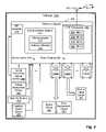
- FIG. 1is an exemplary functional block diagram illustrating a cellular-based system for wireless communication with a telemetry system coupled to a vehicle according to an embodiment of the present invention.
- FIG. 2is an exemplary functional block diagram illustrating a telemetry system coupled to a vehicle according to an embodiment of the present invention.
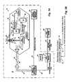
- FIG. 3Ais an exemplary functional block diagram of a cellular communication system according to an embodiment of the present invention.
- FIG. 3Bis a table that shows an exemplary format for a data message communicated in the cellular communication system of FIG. 3A according to an embodiment of the present invention.
- FIG. 4is a schematic illustration of an exemplary wireless communication link according to an embodiment of the present invention.
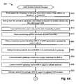
- FIGS. 5A and 5Bare a flowchart of an exemplary process for remotely disabling a vehicle according to an embodiment of the present invention.
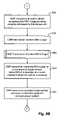
- FIGS. 6A and 6Bare a flowchart of an exemplary process for enabling a vehicle to start according to an embodiment of the present invention.
- FIG. 7is a flowchart of an exemplary process for decoding a message transmitted on an overhead control channel according to an embodiment of the present invention.
- FIGS. 8A , 8 B, and 8 Care a flowchart of an exemplary process for locating a vehicle via wireless communication according to an embodiment of the present invention.
- FIG. 9is a functional block diagram of an exemplary microprocessor system that a telemetry system comprises according to an embodiment of the present invention.
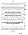
- FIG. 10is a flowchart of an exemplary process for operating a telemetry system in a manner that controls electrical power consumption.
- FIG. 11is a flowchart of an exemplary process for operating a global positioning sensor in a manner that reduces its net power drain.
- FIG. 12is a flowchart of an exemplary process for operating a relay in a manner that reduces its power consumption.
- FIG. 13is a flowchart of an exemplary process for controlling power consumption by a CMR transceiver according to an embodiment of the present invention.
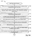
- FIGS. 14A and 14Bare a flowchart of an exemplary process for unlocking a door of a vehicle from a remote location.
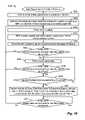
- FIG. 15is a flowchart of an exemplary process for tracking the position of a vehicle via wireless telemetry according to an embodiment of the present invention.
- FIG. 16is a flowchart of an exemplary process for identifying a vehicle's speed limit violations via wireless telemetry according to an embodiment of the present invention.
- FIG. 17is a flowchart of an exemplary process for reporting instances of a vehicle moving outside an operating boundary according to an embodiment of the present invention.
- FIGS. 1 and 2provide block diagram illustrations of an exemplary implementation of a telemetry system coupled to vehicle.
- FIG. 3illustrates an exemplary cellular communication system.
- FIG. 4illustrates an exemplary communication link based on cellular control channels.
- FIGS. 5-8illustrate flowcharts for exemplary processes involving wireless communication in a vehicle telemetry application.
- FIG. 9illustrates an exemplary microprocessor system comprising software modules.
- FIGS. 10-13illustrate flowcharts for exemplary processes for conserving power consumption of a telemetry system.
- FIGS. 14-17illustrate flowcharts foe exemplary application-oriented processes for a telemetry system.
- FIG. 1this figure illustrates a functional block diagram of a cellular-based system 100 for wireless communication with one or more vehicles 105 according to an exemplary embodiment of the present invention.
- each vehicle 105can be a member of a fleet that is dispersed across a geographic area, such as a city, portion of a city, region, state, or larger area.
- a business entitysuch as a trucking company, can operate such a fleet and manage various operational aspects via wireless communication.
- an owner of a specific vehicle 105can send commands to and receive operational data from that vehicle 105 via the cellular-based system 100 .
- the vehicle 105can be a car, truck, train, tractor-trailer truck, delivery van, boat, ship, airplane, etc.
- Each vehicle 105has a telemetry system 165 that senses and controls various aspects of the vehicle 105 or the vehicle's operating environment.
- the vehicle's ownercan remotely disable the vehicle 105 or determine its geographic location from the web-based graphical user interface (“GUI”) 125 , for example.
- GUIgraphical user interface
- a CMR transceiver 160 and its associated antenna 155communicate data over a bidirectional wireless link 140 in a CMR system 8 .
- the CMR transceiver 160comprises circuitry (not shown) for processing incoming and outgoing wireless signals through the CMR system 8 .
- the CMR system 8includes a cellular network 130 that supports wireless communication between a communication gateway 135 and the CMR transceiver 160 .
- Communications 145 in the CMR system 8 from the communication gateway 135 to the CMR transceiver 160transmit in the cellular network's paging channels or FOCCs.
- Communications 146 from the transceiver module 160 to the communication gateway 135transmit in the cellular network's RECCs.
- the data processing system 46 depicted in FIG. 1can support multiple communication applications in tandem with vehicular communication.
- a single CMR system 8can carry voice communications while carrying data communications associated with vehicles 105 and a variety of other equipment (not shown in FIG. 1 ).
- the depicted communication system 100provides economical two-way communications between remote equipment and a central facility using an underutilized portion of an AMPS cellular telephone system, the overhead control channels.
- a system other than an AMPS cellular telephone systemconveys data from the vehicle 105 to the data processing system 46 (and visa versa).
- a non-AMPS systemcan be either a cellular or a non-cellular system based on various transmission protocols.
- communication between the vehicle 105 and the data processing system 46comprises digital transmission or short message service (“SMS”) transport.
- SMSshort message service
- the communication system 100can comprise Digital AMPS (“DAMPS”), Code Division Multiple Access (“CDMA”) or Interim Standard 95 (“IS-95”), Time Division Multiple Access (“TDMA”) or Interim Standard 136 (“IS-136”), the Global System for Mobile communications (“GSM”), Enhanced Data Rates for Global Evolution (“EDGE”), General Packet Radio Service (“GPRS”), or various two-way paging protocols, to name a few alternatives.
- DAMPSDigital AMPS
- CDMACode Division Multiple Access
- IS-95Time Division Multiple Access
- TDMATime Division Multiple Access
- IS-136Interim Standard 136
- GSMGlobal System for Mobile communications
- EDGEEnhanced Data Rates for Global Evolution
- GPRSGeneral Packet Radio Service
- the system's wireless transportcan support a data capacity of 8,000 bits per second or more, for example.
- the communication system 100is based on the communication platform marketed by Numerex Corp. of Atlanta, Ga. under the registered trademark “CELLEMETRY” and can have an uplink pay
- the communication system 100comprises a satellite data link, such as provided by the system that Vistar Datacomm markets under the name “GlobalWave”®, and can have an uplink payload size of 88 bits.
- the communication system 100is linked to the communication service that Aeris.net of San Jose, Calif. markets under the name “MicroBurst”®.
- each telemetry packet 146comprises a 32-bit word or has a 32-bit word payload.
- each telemetry packetcan have a larger payload such as a payload in a range of 32 to 300 bytes.
- each telemetry packetcomprises 88 bits.
- the CMR transceiver 160which may also be referred to as a transceiver module or as a transmitter-receiver pair, receives data communicated in the form of incoming pages 145 transmitted over the cellular network 130 on the FOCC.
- Pages 145 received by the transceiver module 160can include commands, programming, prompts, instructions, requests for telemetry data, and configuration data, to name a few examples.
- a page 145can comprise a request to the telemetry system 165 to report the vehicle's location or an instruction to unlock the vehicle 105 , for example.
- Communication between the communication gateway 135 and the cellular network 130can conform to any one of a variety of communication protocols such as SS7 and IS-41.
- SS7is a communications protocol historically used to transfer public switched telephone network (“PSTN”) data traffic onto a separate wireline or wireless network rather than the originating network for the call.
- PSTNpublic switched telephone network
- IS-41is a standard for communications between cellular systems.
- a data processing system 46typically collocated with the communication gateway 135 , communicates with this gateway 135 via transmission control protocol and Internet protocol (“TCP/IP”) over a hardwire data link 48 .
- TCP/IPis a communication method that combines TCP and IP functions. While IP handles data delivery, TCP tracks packets, which are units of data, divided for efficient routing through a communication network, such as the Internet 120 . More specifically, TCP provides a transport function that matches the message sizes on either end of a communication link and thereby ensures that messages received at a destination are the correct messages intended for that destination.
- the IP functionincludes a computer address on a network. Each computer in a TCP/IP network has a specified address that may be permanently assigned or reassigned at each startup.
- TCP/IP messagescontain an address of a destination network as well as an address of a destination station on the destination network
- TCP/IP messagesreadily transmit across or between multiple networks, such as the Internet 120 and the cellular network 130 of the cellular based system 100 that FIG. 1 depicts.
- the data processing system 46comprises data processing programs 170 that process incoming data from the communication gateway 135 and handle various aspects of outgoing communication.
- the data processing system 46can also comprise one or more databases (not shown) that store or archive processed or raw data passing through the communication gateway 135 .
- Certain of the data processing programs 170may be specific to the vehicle application while other data processing programs 170 support data services with other equipment connected to the CMR radio telephone system 8 , such as electrical utility monitors or vending machines (not shown). That is, these programs 170 may process incoming and outgoing messages from multiple applications that transmit data through the CMR system 8 via the communication gateway 135 .
- the data processing system 46comprises an interactive voice response (“IVR”) module 190 that can include software programs.
- IVRinteractive voice response
- An owner of the vehicle 105 or other authorized individualcan interact with the IVR module 190 by placing a wireline or wireless telephone call to a telephone number dedicated to the data processing system 46 .
- a PSTNwhich FIG. 1 does not explicitly illustrate, can carry the incoming call to the data processing system 46 .
- the IVR module 190answers the incoming call and interacts with the owner. For example, the IVR module 190 can ask the owner to identify a specific service request, such as identifying the vehicle's location, disabling the vehicle 105 or the vehicle's starter, or unlocking the vehicle's doors.
- the IVR module 190can interpret the owner's spoken request and respond accordingly.
- the IVR module 190can initiate sending a message via one or more FOCCs to the CMR transceiver 160 .
- the messagecould comprise an instruction to return the vehicle's location, to disable the vehicle 105 , or to unlock the vehicle's doors, for example.
- GUIgraphical user interface
- a vehicle ownercan enter into the GUI 125 a request for data from the telemetry system 165 or a command that controls some aspect of the vehicle's operations, such as arming a security system or unlocking the vehicle's doors.
- the GUI 125can also display data transmitted by the CMR transceiver 160 to the data processing system 46 .
- the Internet 120 that connects the data processing system 46 to the GUI 125allows a user, such as the vehicle's owner, to interact with the vehicle 105 and its telemetry system 165 from essentially any facility or site that provides Internet connectivity.
- the GUI 125can comprise a personal computer (“PC”) though which the user enters data, requests information, performs other input-related interactions, and views displayed data, operational recommendations, and other information.
- the PCor another computer, can include various software modules (not shown) that perform high-level data processing in collaboration with the data processing programs 170 of the data processing system 46 , for example. Such software modules can output recommendations to the user for example.
- the depicted Internet network 120is replaced with an intranet that communicates information within a campus and thus offers access to the data processing system 46 and its software functions, as available, to users throughout the campus.
- a distributed computing networklinks the web-based GUI 125 to the data processing system 46 .
- FIG. 2this figure illustrates a functional block diagram of a vehicle 105 coupled to a telemetry system 165 for bidirectional communication with a remote data processing system 46 according to an exemplary embodiment of the present invention.
- the telemetry system 165interfaces with sensing devices 290 , 260 , 270 , 275 and control devices 280 , 290 , 295 linked to the vehicle's operation or operating environment.
- Exemplary sensing devices 250 , 260 , 270 , 275can measure, monitor, or detect some aspect of the operation or state of the vehicle 105 or the vehicle's operating environment.
- exemplary control devices 280 , 290 , 295can change, alter, or refine some aspect of the operation or state of the vehicle 105 or the vehicle's operating environment.
- the telemetry system 165comprises such sensing and control devices.
- the telemetry system 165can also interface with external sensing and control devices.
- the telemetry system 165can either comprise or interface with a controller, such as a programmable logic controller (“PLC”).
- PLCprogrammable logic controller
- Such an interfacecan comprise a serial link, parallel bus, current loop, optical link, or other communication link.
- the global positioning sensor (“GPS”) 250determines the geographic position, speed, and heading of the vehicle 105 based on signals from a system of satellites orbiting the earth.
- a serial or parallel link between the GPS 105 and the telemetry system 165supports device-to-device communication.
- the telemetry system 165can prompt the GPS 250 to output navigational data for logging or for transmission to the data processing system 46 via the CMR system's overhead control channels 140 .
- the telemetry system 165can also control power to the GPS 250 , for example turning it off or on based on need or in response to an event.
- other forms of navigational devices or position sensorscan report navigational information to the telemetry system 165 .
- a speedometer and compass(not shown) can provide speed and directional information to the telemetry system 165 .
- the telemetry system 165comprises sensor inputs 240 that support lower data rates.
- One of the sensor inputs 240interfaces with an airbag deployment sensor 260 that provides status of the vehicle's airbag.
- the airbag deployment sensor 260can output a single pulse or toggle (close or open) a contact or switch upon airbag deployment.
- the telemetry system 165can receive notification of the airbag's deployment from the airbag deployment sensor 260 and send a wireless message to a remote owner of the vehicle 105 . That message, which transmits over the overhead control channel link 140 , can serve as an indication to the vehicle's owner that the vehicle 105 may have been involved in an accident.
- a change in the status of the airbag deployment sensor 260may also indicate another condition or event of interest to the owner, for example airbag tampering or unwanted intrusion.
- the security system 270monitors the vehicle 105 for theft, malicious activities, break in, security threats, or similar conditions or events posing the possibility of compromising the vehicle 105 .
- Car manufacturers or dealersoften offer such security systems 270 as purchase options.
- the security system 270can be an aftermarket device.
- the security system 270Upon detecting a threatening condition or intrusion, the security system 270 outputs a signal that the telemetry system 165 receives through one of its sensor inputs 240 .
- Receiving a threat notification from the security system 270can trigger the telemetry system 165 to send notification of the threat to the GUI 125 for display to the owner.
- software modules 215 in the microprocessor system 210can comprise instructions that apply logical rules to the state of the vehicle 105 as determined by the sensor inputs. Based on such rules, the telemetry system 165 can respond to the threat by sending the vehicle's location to the GUI 125 , tracking the vehicle's movements, or disabling the vehicle's starter circuit 280 , for example.
- the ignition switch sensor 275identifies an operational status or state of the vehicle 105 . That sensor 275 can determine if the ignition is off, indicating that the vehicle 105 and the vehicle's engine are off or not running. A driver normally turns the ignition or ignition switch to the off setting to park or store the vehicle 105 . The sensor 275 can also determine if the ignition is on, which is the state for driving the vehicle 105 in which the vehicle's engine runs. The ignition sensor 175 can further identify the ignition's start state. That is, the sensor 175 can determine whether the driver has turned the key to a position for starting the vehicle's engine. Thus, the ignition switch sensor 275 can provide the telemetry system 165 with information regarding whether a driver has attempted to set the vehicle into one of three states, namely on, off, and start.
- the telemetry system 165comprises relays 230 that support outputting signals to various electrical, mechanical, or computer-based systems of the vehicle 105 .
- Software programs, in the form of software modules 215 , executing on the microprocessor system 210can energize each these relays 230 to control a device, circuit, or system connected thereto.
- Energizing a relay 230can comprise sending electricity to or removing electricity from a relay's coil to either open or shut the relay 230 . That is, the microprocessor system 210 can close a relay 230 that is normally open, in its un-energized or relaxed state. Conversely, a signal from the microprocessor system 210 can open a relay 230 that is normally closed, in its un-energized or relaxed state.
- the telemetry system 165can interface to other output devices, including solid state systems such as amplifiers, silicon control rectifiers, operational amplifiers, diodes, or other devices that control or manipulate electricity.
- the relay 230 acan interface to the starter circuit 280 or the door lock/unlock circuit 290 .
- the state of the dual inline pin switches 220as set during installation of the telemetry system 165 , can specify whether the relay 230 a controls starting the vehicle 105 or unlocking the vehicle's doors.
- the telemetry system 165can set or trip the relay 230 a to prevent unauthorized starting of the vehicle 105 .
- the telemetry system 165energizes the relay during an unauthorized attempt to start the vehicle 105 , thereby interruption the starting process.
- the relay 230 acan send a pulse of electricity to an electromechanical apparatus, such as a solenoid, linked to the vehicle's door locks.
- the interval of electrical energycan lock or unlock the door lock of the vehicle 105 .
- the relay 230 binterfaces with the vehicle's horn or lights circuit 295 .
- a vehicle owner who can not locate the vehicle 105 in a crowded parking lotcan place a cellular telephone call to an operator at the data processing system 46 and request help.
- the operatorcan initiate sending a page 145 on an overhead control channel 140 to the telemetry system 165 .
- the telemetry system 165can engage the relay 230 b to pulse the vehicle's horn or lights.
- the microprocessor system 210controls operations of the telemetry system 165 based on sensory information and commands received via the control channel data communication link 140 .
- That system 210comprises a microprocessor 212 or microcontroller that executes instructions or code of the software modules 215 .
- the microprocessor system 210can comprise a variety of digital circuitry elements including flash memory, random access memory (“RAM”), a digital-to-analog converter (“DAC”), an analog-to-digital converter (“ADC”), and timing circuits. Flash memory can facilitate software upgrades or replacements. RAM can support data storage and program execution.
- RAMrandom access memory
- DACdigital-to-analog converter
- ADCanalog-to-digital converter
- Flash memorycan facilitate software upgrades or replacements.
- RAMcan support data storage and program execution.
- the microprocessor system 210can further comprise various types of memory such as any one or combination of volatile memory elements (e.g., forms of RAM such as DRAM, EPROM, EEPROM, SRAM, SDRAM, etc.) and nonvolatile memory elements (e.g., ROM, hard drive, tape, CDROM, etc.).
- volatile memory elementse.g., forms of RAM such as DRAM, EPROM, EEPROM, SRAM, SDRAM, etc.
- nonvolatile memory elementse.g., ROM, hard drive, tape, CDROM, etc.
- the microprocessor system's memorymay incorporate electronic, magnetic, optical, and/or other types of storage media and can have a distributed architecture, where various components are situated remote from one another, but can be accessed by the microprocessor 212 or other computer of the telemetry system 165 .
- a “computer-readable medium”can be any means that can store, communicate, propagate, or transport a program for use by or in connection with an instruction execution system, apparatus, or device.
- the computer readable mediumcan be, for example but not limited to, an electronic, magnetic, optical, electromagnetic, infrared, or semiconductor system, apparatus, device, or propagation medium.
- the computer-readable mediumwould include the following: an electrical connection (electronic) having one or more wires, a portable computer diskette (magnetic), a RAM (electronic), a read-only memory (ROM) (electronic), an erasable programmable read-only memory (EPROM, EEPROM, or flash memory) (electronic), an optical fiber (optical), and a portable compact disc read-only memory (CDROM) (optical).
- the computer-readable mediumcould even be paper or another suitable medium upon which the program is printed, as the program can be electronically captured, via for instance optical scanning of the paper or other medium, then compiled, interpreted or otherwise processed in a suitable manner if necessary, and then stored in a computer memory.
- the microprocessor system 210can also comprise logic implemented in hardware with any or a combination of the following technologies, which are each well known in the art: a discrete logic circuit(s) having logic gates for implementing logic functions upon data signals, an application specific integrated circuit (ASIC) having appropriate combinational logic gates, a programmable gate array(s) (PGA), a field programmable gate array (FPGA), etc. Further a microcontroller, functioning as the microprocessor 212 , can comprise an integration of such digital logical devices.
- the CMR transceiver 160 and it control channel data link 140provide the microprocessor system 210 and the telemetry system 165 with connectivity to remote users and sites, including the web-based GUI 125 and the data processing system 46 . That is a wireless transmitter and receiver pair, embodied in the CMR transceiver 160 and its associated antenna 155 , implements the transmission and reception of data via the wireless data link 140 .
- the CMR transceiver 160has a plurality of MINs 201 , 202 , 203 , 204 for bidirectional communication over the data link 140 through the antenna 155 .
- the telemetry system 165uses these MINs 201 , 202 , 203 , 204 for communication in a coordinated manner that enhances the bandwidth or data carrying capacity of the control channel data link 140 and reduces communication latency, dead time, delay, or lag.
- the four MINs 201 , 202 , 203 , 204function as a collaborative group and achieve a communication advantage over four individually operating MINs (not shown).
- FIGS. 3A and 3Ban exemplary embodiment of a CMR system will be discussed in the context of general applications that can include voice and data communication, mobile communication, vending machines, vehicles 105 , utility monitors, and other equipment.
- FIGS. 3A and 3Brespectively illustrate a CMR system 8 and its messaging packet format.
- the system 8can provide a wide range of voice and data services in addition to communication with an individual machine, such as a vehicle 105 .
- the system 8can interface with a network of machines, such as a fleet of vehicles or a system of vending machines dispersed throughout a geographic region.
- the following discussion of these figuresis somewhat generalized rather than directed specifically a single application.
- FIG. 3Athis figure illustrates a functional block diagram of a data message system 10 in an operating environment of a CMR system 8 in accordance with an exemplary embodiment of the present invention.
- the data message system 10communicates data collected from remote data sources 30 , such as a vehicle 105 or a GPS 250 as depicted in FIGS. 1 and 2 , and includes a set of data reporting devices 29 , at least one MSC 24 of the CMR system 8 , and a data collection system 40 connected to the MSC 24 .
- each reporting device 29comprises the telemetry system 165 coupled to the vehicle 105 illustrated in FIGS. 1 and 2 and discussed above.
- the data collection system 40can be the communication gateway 135 of FIGS. 1 and 2 .
- Each data reporting device 29monitors operation of the remote data source 30 to obtain selected data, such as the location, speed, or security status of the vehicle 105 .
- the data reporting device 29transmits data messages containing selected data to the MSC 24 via a cellular network control channel of the CMR system 8 .
- the MSC 24receives data messages from data reporting devices 29 operating within coverage areas of the CMR system 8 .
- the MSC 24sends the data messages to the data collection system 40 via a first communications link for processing of the information offered by the data messages.
- a remote data sitecan be a parking lot, driveway, freeway, city, road, or other site that the vehicle 105 occupies, for example.
- the data message system 10adapts the existing environment of a CMR system 8 to communicate data from one or more remote sites to a central location. However, to conserve the use of voice channels of the CMR system 8 for telephone conversations, the data collection system 40 uses the cellular network control channel of the CMR system 8 for data communications.
- the data messageis formatted to correspond to a call origination signal, which is normally transmitted by a cellular radiotelephone unit when the device originates a cellular telephone call for communication via a CMR system 8 . This permits conservation of the valuable frequency spectrum dedicated to the voice channels of the typical CMR system 8 .
- one exemplary embodiment of the present inventioncan adapt existing architecture and communications protocols of a typical CMR system 8 to supply an economical approach to the communication of telemetry data collected from numerous remote sites or vehicles 105 . It will be further understood that the communication of data messages between an MSC 24 and the cellular communications device can be based upon established techniques and known protocols for CMR system communications. Accordingly, it will be useful to review the primary components and operation of a typical CMR system 8 .
- a CMR system 8is generally characterized by dividing a radio coverage area into smaller coverage areas or “cells” 12 using low power transmitters and coverage-restricted receivers.
- the limited coverage areaallows the radio channels used in one cell 12 to be reused in another cell (not shown).
- control circuitry associated with each cell 12detects that the signal strength of the mobile radiotelephone in the just-entered cell 12 is stronger, and communications with the mobile radiotelephone are “handed-off” to the just-entered cell 12 .
- a CMR system 8typically uses a pair of radio frequencies for each radio channel and each cell 12 .
- Each cell 12typically includes at least one signaling channel, also referred to as a cellular network overhead control channel or an access channel, and several voice channels.
- the overhead control channelis selected or dedicated to receive requests for service from mobiles and portables, to page selected mobiles or portables, and to instruct the mobiles or portables to tune to a predetermined voice channel where a conversation may take place. Accordingly, the overhead control channel is normally responsible for receiving and transmitting data to control the communication actions of the mobile and portable radiotelephones.
- the overhead control channelnormally comprises a FOCC for communications from the MSC 24 to a radiotelephone unit and a RECC for communications from a radiotelephone unit to the MSC 24 .
- the FOCCsupplies a multiplexed data stream of message data words, a busy idle signal, and busy idle bits.
- the busy idle bitssupply a status indication of the RECC to monitoring radiotelephones. If a radiotelephone unit is using the RECC, then the RECC is considered busy and the busy idle bit is set to a binary one value. Alternatively, if the RECC is free or not in use, then the RECC is considered idle and the busy idle bit is set to a binary zero value.
- Mobile radiotelephonesmonitor the busy idle bits transmitted by the FOCC and, if the busy idle bit is set to a binary one value, then the mobile radiotelephone delays transmission on the RECC until the busy idle bit is set to a binary zero value.
- a radiotelephonenormally transmits on the overhead control channel during the window of opportunity that a transition from the busy state to the idle state presents.
- the busy idle bitsupplies an instantaneous view of the signaling activity on the overhead control channel, and the radiotelephone is responsive to this instant snapshot of overhead control channel activity.
- EIA/TIA Standard 553The data message and radio channel specifications for U.S. cellular radiotelephone systems are set forth in EIA/TIA Standard 553, implemented in accordance with 47 C.F.R. Section 22, in the Report and Orders pertaining to Federal Communications Commission (“FCC”) Docket No. 79-318. Copies of the EIA/TIA-553 may be obtained from the Engineering Department of the Electronic Industries Association at 2001 Pennsylvania Avenue N.W., Washington, D.C., USA 20006.
- a cellular mobile radiotelephoneWhen a cellular mobile radiotelephone originates a call, it transmits at least one data message to the serving cell 12 of the CMR system 8 .
- This request for a cellular voice channelis defined by EIA/TIA-553 and can be implemented as a message or signal having certain defined fields.
- this call origination messagecan contain data fields for the low-order seven digits of the unit's telephone number, known as the MIN, the unit's station class mark (“SCM”), which identifies functional characteristics of the unit, and the called address, or dialed telephone number.
- MIN2the unit's station class mark
- NPAnumber planning area
- the MINis assigned to a particular radio telephone unit by the cellular service provider selected by the subscriber.
- the MINtypically contains information unique to the CMR system operator, for example, the first three digits of the MIN (“XXX”) typically correspond to an area code, the next three digits (“XXX”) typically correspond to a geographic location within the area code; and the final four digits (“XXXX”) identify a particular piece of equipment.
- the ESNis unique to each mobile cellular radiotelephone unit, and comprises a format that allows differentiation as to manufacturer and, in some cases, the model number, date of manufacture, and the like.
- the call origination messageis provided first to the serving cell 12 of the CMR system 8 , and then through a data link to a MSC 24 , which is sometimes referred to as a mobile telephone switching center or a “switch.”
- the MSC 24makes voice connections between mobile radiotelephones and other telecommunications networks.
- Software executing at the MSC 24typically determines whether the radiotelephone identified by the message is an authorized user or subscriber by looking up the unit's telephone number, serial number, and other information supplied by the message to see if there is an entry in the MSC's user database (not shown) corresponding to that particular telephone.
- An optional function of an MSC 24is to validate that the ESN and MIN received as part of a call origination message are valid.
- the MSC 24compares the received ESN to a user database entry to detect fraud. If these checks succeed, the cellular call is then allowed to proceed.
- the radiotelephoneWhen a mobile radiotelephone first powers up or first enters a CMR system 8 when already powered, the unit can identify itself as actively present within the system.
- the radiotelephoneidentifies itself or registers through a process known as autonomous registration by supplying a data packet of information similar to that of a call origination message.
- the autonomous registration signalalso referred to as a registration or an identification signal, typically comprises data fields for at least a mobile telephone number, i.e., the MIN, and an ESN.
- the call origination signalcan include a data field containing the digits of the telephone number to be called, and a flag within a data field to distinguish this message from a registration signal.
- An original design goal of autonomous registrationwas improving the efficiency of potential future call deliveries by informing the MSC 24 of the approximate whereabouts of each individual radiotelephone unit and by reducing paging channel load by lessening the need to page all cells 12 to find a particular cellular unit.
- the MSC 24can later page or attempt to ring the cellular unit only in the cell 12 or area of the cellular unit's last known location. Additional cells 12 would be paged only if the initial page did not locate the particular radiotelephone.
- the autonomous registration functioncan be implemented as messages periodically and autonomously sent from the mobile radiotelephone to the serving cell 12 at an interval specified in data parameters previously received from the cell 12 by the cellular unit.
- a subscriber using or attempting to use his or her mobile radiotelephone in a service area outside the home service areais said to be roaming, and he or she (and the associated mobile radiotelephone unit) is commonly referred to as a roamer.
- the radiotelephonewill subsequently receive a message via the overhead control channel of the particular cell 12 in which the telephone then resides. This message will include a request that the subscriber register for operation in the particular cellular system.
- the radiotelephone unittransmits both the mobile telephone number and the serial number as identifying information back to the cell site 12 .
- the cell 12forwards this information to a MSC 24 , which quickly ascertains whether the radiotelephone unit is a customer of the local cellular service provider or the customer of another cellular system.
- the MSC 24will send a message packet to the home system for the particular telephone unit. This message indicates that the particular radio telephone unit has registered in another cellular system and requests information about the validity of the number and account information for the radio telephone unit. The home system responds by transmitting a responsive packet containing the requested information. If valid, the MSC 24 at the foreign cellular system will then add the roamer to its list of registered users and the home cellular system will add the subscriber associated with the radio telephone unit to a list of roamers that are out of the service area and registered in another area.
- the user database at the MSC 24 for the home systemwill observe that the unit has moved again and will update the database list of where the roaming unit has most recently registered in a user database system. In addition, it will send a message to the first foreign system providing notification that the roaming unit has now moved on and registered in another system, and that the first foreign system should delete the particular unit from its list of registered roamers. In this manner, the user databases at the various MSCs 24 are not cluttered with data identifying previously registered roamers as valid accounts for which service should be provided, when these roamers may have long since left the area of service.
- the data message system 10supports the collection and communication of data to a central data collection site 40 by reporting systems associated with numerous data sources 30 .
- a typical CMR system 8includes a geographic radio service area, such as indicated by the cell 12 , of which a plurality of cells are typically provided in a typical cellular service operator's system.
- the cell 12is served by a broadcast antenna 14 to permit communications between cellular mobile radiotelephones operating within the cell 12 and a cell control 16 .
- a mobile telephone switching office, such as the MSC 24can communicate with the cell 12 either by dedicated telephone facilities (not shown) or, more frequently, by a cell-to-mobile switching center data link 22 between the cell control 16 and the MSC 24 .
- At least a portion of the data link 22is typically supported by a wireless communications link, such as the microwave link 20 , located between the cell 12 and the MSC 24 .
- a typical CMR system 8comprises at least one mobile telephone switch coupled to an appropriate array of more or less identically equipped cell sites 12 .
- the MSC 24normally couples telephone conversations involving mobile radiotelephones operating in the cell 12 to the PSTN 26 through telephone facilities 26 .
- the data collection system 40includes a set of data reporting devices 29 , each comprising at least one monitor 32 for collecting data from remote data sources 30 and a cellular communications device 34 for communicating the collected data via an overhead control channel of the CMR system 8 to the MSC 24 .
- the monitor 32 depicted in FIG. 3Awhich is connected to a corresponding remote data source 30 via a signal path 31 , obtains and records selected data directed to the operation or performance characteristics of the data source 30 .
- each data reporting device 29can comprise a CMR transceiver 160 coupled to one or more vehicle systems, via a telemetry system 165 as described above.
- the monitor 30can include a GPS 250 , an airbag deployment sensor 260 , or a security system 270 .
- the monitor 30can also comprise a control function that may be integral with or separate from the telemetry system 165 .
- the cellular communications device 34which is connected to the corresponding monitor 32 via a signal path 33 , prepares a data packet containing the selected data and transmits the packet as a data message.
- the communication device 34can comprise the CMR transceiver 160 illustrated in FIGS. 1 and 2 and discussed above.
- the selected datarepresents actual data acquired by the monitor 32 in response to monitoring the operation or performance of the data source 30 .
- the selected datacan represent predetermined data or a preprogrammed message that is associated with the detection of a certain event by the monitor 32 for the data source 30 .
- the MSC 24receives the data message via a cellular network overhead control channel 38 formed by the combination of the data link 22 and a cellular communications link 36 between the broadcast antenna 14 and the cellular communications device 34 .
- This combination of communications linksis collectively referred to as the overhead control channel.
- a cellular network control channel for a typical CMR system 8comprises two radio channels that are commonly described as a FOCC and a RECC, as described above.
- the FOCCserves communications initiated by the MSC 24 to a radiotelephone unit, while the RECC serves communications from the radiotelephone to the MSC 24 .
- the communications operations between the MSC 24 and the cellular communications device 34also follow this convention.
- the overhead control channel 38comprises two separate data communications paths, an FOCC for communications initiated by the MSC 24 and an RECC for communications initiated by the cellular communications devices 34 (or mobile radiotelephones operating within the cell 12 ). Accordingly, the cellular communications device 34 transmits data messages via the RECC, whereas the MSC 24 transmits command signals via the FOCC.
- the MSC 24receives data messages from each of the cellular communication devices 34 operating within the coverage areas of an array of cells for the CMR system 8 .
- the data messagescontain selected data rather than the parameters normally contained in an actual radiotelephone control information
- the MSC 24operates upon the data messages as if they were transmitted by a cellular radiotelephone unit operating within the coverage area of the CMR system 8 because the format of the data messages makes them appear as typical call origination signals generated by a radiotelephone unit.
- the MSC 24in response to a data message, can conduct one or more of the following operations: store the data message for processing at a later date, process the selected data supplied by the data message, or forward the data message to a data collection system 40 via a first communications link 42 .
- the data collection system 40which is connected to a memory storage device 44 , collects the selected data by storing the received data messages within the memory storage device 44 . Similar to the MSC 24 , the data collection system 40 also can process the selected data to obtain further information concerning the operation or performance of the data sources 30 . Alternatively, the data collection system 40 can send the information of the data message to a data processing system 46 via a second communications link 48 .
- the data processing system 46is typically remotely located from the data collection system 40 and facilitates convenient processing of the selected data at a central site.
- the second communications link 48is typically implemented by a telephone facility, a dedicated data link, or by a wireless communications link.
- the data collection system 40can acquire data from a wide variety of data sources, such as utility meters, CATV PPV terminals, vending machines, equipment operating at isolated sites, industrial machinery, security alarm systems, etc.
- the data collection system 40can monitor one or more loads of an electrical utility system and communicate energy consumption data to a central site for processing.
- the utility industrytypically determines the effectiveness of an electrical load management system for a selected control scenario by collecting or monitoring energy consumption data for certain customers during load management activities. In particular, the utility compares the maximum energy consumed by the selected customers for certain collection periods to the maximum energy that would be consumed by those customers in the absence of any load management activities.
- a utilitytypically uses a load profile recorder located proximate to each customer's electrical load for recording the customer's power consumption during predetermined time intervals. Upon the conclusion of the collection period, the recorded energy consumption data is then forwarded from each load profile recorder to a central data processing site such as the illustrated data processing system 46 , for data translation and evaluation.
- the CMR system 8can support the operations of such an electrical utility application in tandem or parallel with the vehicle application and other applications.
- Select monitors 32operate as recorders to obtain operational data from the data sources 30 , such as sensors coupled to the vehicle 105 .
- the cellular communications device 34thereafter transmits a data message containing this operational data to the MSC 24 .
- the MSC 24can then forward the data message to the data collection system 40 for processing of the data or, in turn, the data collection system 40 sends the data message to the data processing system 46 for processing operations.
- an operator of a system or fleet of vehicles 105can collect operational data from each vehicle 105 in the fleet to support evaluating and optimizing the effectiveness and profitability of its business operations.
- the MSC 24in response to the transmission of a data message by a cellular communications device 34 , the MSC 24 typically makes a determination whether the cellular communications device 34 that transmitted the data message is an authorized user or subscriber of the services offered by the cellular system 8 or another system.
- the data messageformatted as a call origination signal associated with the call origination function, can include certain information that identifies the cellular communications device 34 as a radiotelephone unit which normally operates within a certain remote or “foreign” cellular system. Based upon this information, the MSC 24 decides that the cellular communications device 34 is a roamer because it appears to subscribe to the cellular service offered by another cellular system, which, in this case, is the data collection system 40 .
- the MSC 24can maintain a list or user database (not shown) having entries corresponding to the identification information in the data message. At least a portion of the identification information identifies the source of the call origination signal as belonging to a particular cellular system. By checking this user database, the MSC 24 determines whether the cellular communications device 34 is a subscriber or a roamer. A subscriber is typically listed as an entry in the user database, whereas a roamer is generally not initially listed in the user database. Thus, it will be understood that the MSC 24 interprets the data message as a transmission from a roaming mobile radiotelephone operating within the CMR system 8 because the user database fails to contain an entry identifying the cellular source as a home unit.
- the remote cellular system identified by the data messagecan be dedicated to data collection applications, rather than voice communications, and is represented by the data collection system 40 .
- This data collection system 40can be the communication gateway 135 depicted in FIG. 1 and described above.
- the remote cellular systemrepresents the home location register (“HLR”) for the cellular service responsible for transmission of the data message.
- HLRhome location register
- the MSC 24forwards the data message to the data collection system 40 via the first communications link 42 .
- the data collection system 40receives the data message containing selected data collected from the remote data source 30 and, unlike the MSC 24 , recognizes that the data message actually contains the desired data collected from a remote data source 30 . Accordingly, the data collection system 40 transmits a message to the MSC 24 that instructs the MSC 24 to delete the cellular communication device 34 from its list of registered roamers. It will be understood that the MSC 24 would normally receive this type of message when a roaming radiotelephone has moved to another cellular system and subsequently registered for operation on that other system. Thus, the user database of the MSC 24 is no longer required to maintain the registration information concerning the cellular communications device 34 after transferring the data message to the data collection system 40 .
- the data collection system 40can respond to the data message by transmitting a message which confirms that the roamer is a valid user and further instructs the MSC 24 to delete the registration entry upon the expiration of the certain time interval.
- the MSC 24can automatically delete a registration entry from the MSC user database upon expiration of a certain time period without any instruction from the data collection system 40 . In this manner, the data collection system 40 is not required to send yet another message to the MSC 24 after the data collection system 40 confirms that the cellular communications device 34 represents a valid user.
- the MSC 24 and the data collection system 40can be compatible with the IS-41 standard that defines a communications protocol for communications between two cellular systems.
- the IS-41 standardincludes provisions that facilitate the handoff of cellular calls between dissimilar cellular systems, not unlike the way that calls are handed-off between cells 12 of a single CMR system 8 .
- the IS-41 standardpermits call deliveries and communications exchange for verifying whether a cellular caller is a valid cellular service subscriber.
- the MSC 24implements the handoff by forwarding the data message to the data collection system 40 via the first communications link 42 , which can be implemented as an IS-41-compatible network.
- the data collection system 40sends a user validation message via the link 42 to confirm that the source of the data message, specifically a cellular communications device 34 , is a valid cellular source.
- the data collection system 40recognizes that the received data message contains selected data which a cellular communications device 34 has transmitted. Accordingly, the data collection system 40 processes the received data message and compares the predetermined identifying characteristic in its data message to a list of such characteristics in its user database. This user database can contain an entry of the predetermined identifying characteristic for each of the known cellular communications devices 34 and corresponding data that identifies the associated device as a valid cellular source. Upon obtaining a positive match, the data collection system 40 responds to the received data message by sending to the MSC 24 a validation message. The validation message confirms that the roamer associated with the data message is a valid or authorized user of the remote cellular system.
- the data collection system 40also advises the MSC 24 to not complete the requested call because there is no need to connect the cellular communications device 34 to a voice channel of the CMR system 8 for completing a voice-based telephone communication. Based on the valid user response, the cellular communications device 34 is thereafter added as a registered cellular source to a user database of registered roamers at the MSC 24 . It will be appreciated that the data collection system 40 also can forward to the MSC 24 a message confirming the absence of a valid entry for the cellular communications device 34 in response to a negative match.
- This validation messagecan also include a profile of communications services that are authorized for use by the particular cellular source.
- this user profiletypically defines operational limitations for the cellular source, including access to long distance services, the capability for the source to only originate (and not receive) calls via the cellular system, etc.
- user profile informationcan contain an instruction that commands the MSC 24 to delete from its user database the registration entry for a particular cellular communications device after the expiration of a defined time period. This function allows the MSC 24 to clear from its user database entries cellular communications devices 34 that have communicated data messages via the MSC 24 when such devices no longer require continued communications support from the MSC 24 . For example, such devices do not require continued support for voice communications because they do not require assignment of a voice channel.
- the data collection system 40can store selected data supplied by the received data message within the memory storage device 44 , can process the selected data and store the resultant data, or can forward the selected data to the data processing system 46 for processing. Prior to sending the selected data to the data processing system 46 , the data collection system 40 first converts the data message to an acceptable communications protocol for conveying the data message to the data processing system 46 . This step may be necessary prior to communication with the data processing system 46 because, unlike the MSC 24 and the data collection system 40 , neither the data processing system 46 nor the second communications link 48 may be compatible with the IS-41 standard.
- the MSC 24may be programmed to treat the cellular communications devices 34 as roamers associated with a foreign cellular system
- the user database of the MSC 24also can be programmed to contain entries for predetermined identifying characteristics of those cellular communications devices 34 operating within cells 12 of the cellular system 8 .
- an MSC 24 containing such user database entriesidentifies the transmitting cellular communications device 34 as a home unit rather than as a roamer because the MSC user database contains an entry that corresponds to the predetermined identifying characteristic supplied by the message.
- the MSC 24registers the transmitting cellular communications device 34 as a home unit of the cellular system 8 . This provision avoids a need to contact a foreign cellular system, such as the data collection system 40 , to inquire whether the cellular source is a valid user or subscriber of cellular services.
- the MSC 24can be adapted to recognize that data messages should still be forwarded to the data collection system 40 . Specifically, based upon a portion of the predetermined identifying characteristic that is uniquely associated with the data collection system 40 , the MSC 24 locates an entry in its user database that commands the switch 24 to send all messages containing such a characteristic to the data collection system 40 . Accordingly, the MSC 24 thereafter forwards the data message via the first communications link 42 to the data collection system 40 .
- the data collection system 40can be implemented by a computer.
- the data collection system 40is the computer of a service circuit node.
- Certain manufacturers of switches, such as the MSC 24also offer devices for implementing communications with the data collection system 40 , including the Motorola EMX switch and other vendor proprietary switches. Switch manufacturers include: AT&T Network Systems, Whippany, N.J.; Ericsson Radio Systems, Richardson, Tex.; Hughes Network Systems, Germantown, Md.; and Motorola, Schaumburg, Ill.
- the cellular system 8is can be implemented as an AMPS or a DAMPS cellular system. However, it will be appreciated that the cellular system 8 also can be compatible with alternative cellular systems implementing an overhead control channel for mobile to cell communications, including the cellular systems known as: DCS 1800, IS 95-CDMA, JTACS, TACS, ETACS, RC 2000, NMT 450, ESMR, WACS, NMT 900, or other wireless systems.
- DCS 1800DCS 1800, IS 95-CDMA, JTACS, TACS, ETACS, RC 2000, NMT 450, ESMR, WACS, NMT 900, or other wireless systems.
- the CMR system 8includes an array of cells, such as the cell 12 , and that a set of reporting systems 29 , each formed by the monitor 32 and the cellular communications device 34 , are typically located in a cell 12 .
- the monitor 32 and the cellular communication device 34can be located proximate to the data source 30 to minimize the lengths of the signal paths 31 and 33 .
- the monitor 32 and the cellular communication device 34can be combined within the same housing and this housing can be installed either adjacent to or as an integral part of the data source 30 .
- the signal path 31 and the signal path 33form hard-wired connections between the connected devices. Nevertheless, it will be appreciated that the signal paths 31 and 33 also can be implemented as either infrared communications links or wireless communications links.
- a single cellular communications device 34can be connected to multiple monitors 32 to permit the transmission of selected data collected from associated data sources 30 located at a central site.
- a single cellular communications device 34can be mounted at a central location within or along an office building and multiple monitors 32 can be distributed throughout the building to permit the acquisition of data from the associated data sources 30 , such as vending machines or utility meters dispersed within the building facility.
- the data collection system 40can be located proximate to or as an integral part of the MSC 24 , in which case the first communication link 42 can form a hard-wired connection between the devices. However, the data collection system 40 also can be positioned at a remote site. For this remote installation, the first communications link 42 can be implemented as a wireless communications system, such as a microwave system, or as a dedicated data line, such as a telephone facility. For the convenience of the party that is sponsoring the collection of a particular type of data, the data processing system 46 is typically located at another remote site that is typically proximate to the sponsoring party.
- FIG. 3Bis a table that shows the format for the data message that is communicated by the data message system 10 .
- a data record 50 for the data messagecontains both a data field 54 for the selected data acquired from the remote data source 30 and another data field 52 for a predetermined identifying characteristic which uniquely identifies the cellular communications device 34 that initiates the transmission of the data message.
- the data fieldscan be separated by one or more selected characters to delimit the data fields.
- the format for the data messagecan be identical to the message format (or data record) of a typical call origination signal that is transmitted by a cellular radiotelephone when it originates a cellular call for communication via a CMR system 8 .
- the cellular communications device 34can mimic the initiation of a cellular telephone call by sending a data message that appears to contain a valid mobile telephone number and an ESN. Although it is not intended for the cellular communications device 34 to place a voiced-based cellular telephone call, the cellular communications device 34 imitates a cellular radiotelephone device by generating the call origination-formatted signal, thereby enabling a data communication of selected data to the MSC 24 .
- the message format for a call origination signalhas been adapted by the data message to permit the identification of the particular transmitting cellular communications device 34 and the communication of the selected data.
- the data field 52 for the predetermined identifying characteristiccorresponds to at least a portion of a mobile telephone number or MIN assigned to the cellular communications device 34 .
- the predetermined identifying characteristicis substituted within the data field normally reserved for the MIN in the call origination signal.
- This predetermined identifying characteristiccan belong to a set of unassigned mobile telephone numbers.
- the predetermined identifying characteristic assigned to each cellular communications device 34can be a telephone number or a set of 10 digits.
- the predetermined identifying characteristicfacilitates identifying the source of the data by uniquely specifying the cellular communications device 34 associated with the remote data source 30 .
- the predetermined identifying characteristicalso supplies information used by the MSC 24 to recognize that the data message containing this predetermined identifying characteristic is associated with the data collection system 40 .
- the data field 54 in the data message for remote datacorresponds to the location within the data record of a call origination signal for the ESN.
- the typical ESN data fieldis 32 bits long and includes 8 bits for a manufacturer code.
- the selected data within the data field 54comprises a length defined by the remaining 24 bits of the ESN.
- a data message having 24 bits of selected data(and, as required, 8 bits of the manufacturer code segment for a ESN) should be sufficient to supply relevant data.
- a “called address field”(not shown), which normally contains the digits for the called party's telephone number, can be used for the placement of selected data within the data message.
- the message protocol for a registration signal associated with the autonomous registration functionalso can be used to send desired information from the cellular communications device 34 to the MSC 24 via the overhead control channel 38 .
- the call origination signalis substantially similar to the signal for the autonomous registration function, with the exception that the call origination signal includes the called address field and a flag to distinguish the call origination signal from the autonomous registration function. This flag permits the CMR system 8 to determine whether a call origination function or a registration function should be conducted in response to a reception of these signals.
- an expandable ESN fieldhas been proposed by members of the cellular radiotelephone industry.
- the CMR system 8can utilize an expandable ESN data field to increase the data carrying capacity of the call origination signal or autonomous registration signal.
- One source of motivation behind this proposalis the potential depletion of available distinctive data sequences for the manufacturer's codes and for other data (e.g., identifying characteristics of each radiotelephone). Because of the increasing popularity of radiotelephones, this depletion has recently become a more imminent concern to the cellular radiotelephone industry.
- the ESN data fieldcan be 32 bits long and can reserve 8 bits for a manufacturer code.
- An expandable ESN data fieldpermits a CMR system 8 to recognize a triggering mechanism within the call origination signal or autonomous registration signal, which alerts the CMR system 8 to look elsewhere in the call origination or autonomous registration signal for additional data.
- Such an expandable ESN data fieldpermits a manufacturer's code to fill the entire ESN data field while permitting the inclusion of additional data within the call origination or autonomous registration signal.
- the additional datawould be accessible to a CMR system 8 that is alerted to the existence of the expandable ESN and to the location of the additional data within the call origination signal or autonomous registration signal.
- the expandable ESN data field conceptcan also be utilized by the data message system 10 .
- the data messageformatted as either a call origination signal or an autonomous registration signal, may contain a predetermined triggering mechanism that indicates the ESN data field contained in the data message is an expandable ESN data field.
- the data collection system 40will be alerted that the ESN data field contains more data than that defined by the EIA/TIA Standard 553 protocol. The data collection system 40 will then look to another portion of the call origination signal or autonomous registration signal for the additional data.
- An expandable ESN data fieldtherefore, can include an ESN data field as well as one or more additional data fields, such as an ESN2 data field.
- a first methodis to include an ESN flag bit in the call origination signal or autonomous registration signal data packet. For example, if the ESN flag bit is set to a binary one value, then the data collection system 40 will be alerted to identify the additional data in another portion of the data packet. If, on the other hand, the ESN flag bit is set to a binary zero value, then the data collection system 40 will not look for additional data, and will merely process the data within the standard data packet.
- a reporting device 29 or a telemetry system 165can have multiple MINs or overhead control channels. That is, the foregoing discussion of FIGS. 3A and B can apply to having a single MIN or overhead control channel for one or more reporting devices 29 or telemetry systems 165 or to having multiple MINs 210 , 202 , 203 , 204 or overhead control channels 410 , 420 , 430 , 440 dedicated to a single reporting device 29 or telemetry system 165 .
- the system illustrated in FIGS. 3A and 3Bsupports the communication link 140 illustrated in FIGS. 1 and 2 and discussed above in reference to those figures.
- FIG. 4this figure illustrates a schematic representation of a wireless communication link 140 according to an exemplary embodiment of the present invention.
- the wireless link 140comprises four overhead control channels 410 , 420 , 430 , 440 with each one having a respective MIN 210 , 202 , 203 , 204 .
- the wireless link 140can operate more effectively or more efficiently than would four individual MINs or four individual overhead control channels functioning in an uncoordinated manner.
- the system 100can establish or use relationships between each of the four illustrated MINS 201 , 202 , 203 , 204 or overhead control channels 1 , 2 , 3 , and 4 410 , 420 , 430 , 440 to enhance the data carrying capacity or capability of the data link 140 .
- the data processing system 46sends commands or pages to the telemetry system 165 on overhead control channels 2 , 3 , and 4 , 420 , 430 , 440 or MINs 2 , 3 , and 4 , 202 , 203 , 204 and receives confirmation registration of command receipt on overhead control channel 1 410 or MIN 1 201 .
- one MIN 202 , 203 , 204 or overhead control channel 420 , 430 , 440can send forward page messages 145 while another MIN 201 or overhead control channel 410 returns reverse responses or telemetry data 146 .
- Using one MIN/overhead control channel to communicate in the forward direction and another MIN/overhead control channel to communicate in the reverse directioncircumvents the delay that an MSC 24 typically needs to prepare a MIN/overhead control channel for reversing its communication direction.
- the CMR transceiver 160 and the data processing systemtypically waits a preset time delay, such as 65 seconds, between receiving a message on a specific MIN/overhead control channel and sending a reply on that same MIN/overhead control channel. Sending on a first MIN/overhead control channel and receiving on a second MIN/overhead control channel avoids this delay.
- the communication link 140dedicates certain overhead control channels or MINs to each of forward and reverse communication for a selected or intermittent time interval.
- a MIN or overhead control channelis permanently dedicated to each of forward and reverse data transmission.
- the microprocessor system 210can interpret or decode a page, message, signal, transmission, or prompt that it receives on a specific MIN/overhead control channel based on information obtained outside of that communication. That is, a recipient of a transmission on an overhead control channel or MIN can associate a specific meaning with the transmission from two or more possible meanings based on information that is available from a source other than that transmission. For example, a transmission can have a first meaning if the recipient is in one state and a second meaning if the recipient is in another state. Another transmission, which may occur on another overhead control channel or MIN, can cause such a state change of the recipient, for example.
- the telemetry system 165interprets a page received on overhead control channel 4 440 or MIN 4 204 as a command to enable starting of the vehicle 105 if the vehicle 105 is in a disabled state.
- a page 145 on overhead control channel 3 430 or MIN 3 203can cause such a disabled state, for example.
- the vehicle 105if the vehicle 105 is in an enabled state at the time of receiving the page 145 on overhead control channel 4 440 or MIN 4 204 , the telemetry system 165 interprets a page 145 on overhead control channel 4 440 or MIN 4 204 as a request to transmit the vehicle's location.
- Creating relationships between pages 145 on individual overhead control channels 410 , 420 , 430 , 440 or MINs 210 , 202 , 203 , 204 of the data link 140can enhance communication efficiency. Receipt (or lack of receipt) of a forward or reverse message 145 , 146 on one overhead control channel 410 , 420 , 430 , 440 or MIN 210 , 202 , 203 , 204 during a specified time interval can specify the meaning of another message on another overhead control channel 410 , 420 , 430 , 440 or MIN 210 , 202 , 203 , 204 .
- a recipientcan interpret a message received on one overhead control channel 410 , 420 , 430 , 440 or MIN 210 , 202 , 203 , 204 as having one of two possible interpretations based on whether the recipient received a message on another overhead control channel 410 , 420 , 430 , 440 or MIN 210 , 202 , 203 , 204 .
- FIG. 4illustrates as a MIN 201 , 202 , 203 , 204 . That is, those skilled in the art will appreciate that communicating MIN 1 201 or communicating on MIN 1 201 , for example, may be viewed as overhead control channel 1 410 carrying a communication.
- the present inventioncan comprise multiple computer programs that embody the functions described herein and that are illustrated in the exemplary functional block diagrams and the appended flowcharts.
- the inventionshould not be construed as limited to any one set of computer program instructions.
- a skilled programmerwould be able to write such a computer program to implement the disclosed invention without difficulty based on the exemplary displays, functional block diagrams, and flowcharts and associated description in the application text, for example.
- FIGS. 5A and 5Billustrate a flowchart of a process 500 , entitled Disable Vehicle, for remotely disabling a vehicle 105 according to an exemplary embodiment of the present invention.
- the web-based GUI 125displays the current state or status of the vehicle 105 .
- the userwho is typically the vehicle's owner, can observe whether starting of the vehicle 502 is enabled or disabled.
- the data processing system 46can maintain this information for ready access via the Internet 120 .
- the system 100can dynamically obtain the vehicle's enabled/disabled status in response to the user logging onto the GUI 125 .
- the userobserves that the GUI 125 indicates that starting of the vehicle 105 is enabled.
- the userenters a request to disable the vehicle 105 into the GUI 125 .
- the usermay press a key or select a designated area on a screen, for example.
- the GUI 125sends the request to the data processing system 46 via the Internet 120 for receipt at Step 515 .
- the data processing system 46determines the assignment or numerical identity of the MIN 3 203 of the CMR transceiver 160 located at the user's vehicle 105 .
- a database at the data processing system 46can maintain this information as a table, for example.
- the data processing system 46transmits the MIN 3 203 , or its numerical identification, to the communication gateway 135 .
- the communication gateway 135receives the MIN 3 203 and inserts it into a page 145 . That is, the communication gateway 135 constructs a page 145 addressed to the CMR transceiver 160 , specifically using MIN 3 203 as the address.
- the communication gateway 135passes the page 145 to the cellular network 130 for broadcast across the CMR system 8 at Step 540 .
- the communication gateway 540causes sending of a signal on the FOCC of the overhead control channel 3 430 . That is, a wireless signal carrying the numerical designation of MIN 3 203 transmits in the cellular network 130 and is available for receipt by various wireless receivers in the network 130 .
- the MIN 3 203specifically matches the user's vehicle 105 and thus causes that vehicle's CMR transceiver 160 to exclusively receive the page 145 .
- Step 545which FIG. 5B illustrates, the CMR transceiver 160 of the user's vehicle 105 recognizes the page 140 comprising MIN 3 203 for receipt at Step 550 .
- the CMR transceiver 160transmits a confirmation registration through the cellular network 130 via the RECC of channel 1 410 in response to receiving the MIN 3 203 . That is, the CMR transceiver 160 receives a message on MIN 3 203 and acknowledges receipt of that message by sending a reply message on MIN 1 201 .
- the communication gateway 135receives the MIN 1 confirmation registration from the cellular network 130 .
- the communication gateway 135passes that confirmation message to the data processing system 46 .
- the data processing system 46receives the confirmation message or registration and places it in a incoming registration table and a corresponding page log table.
- the data processing system 46maintains a record of messages sent on FOCCs and replies received on RECCs.
- the telemetry system 165interprets the page 145 on MIN 3 203 as a command to disable the vehicle's starter. Specifically, the CMR transceiver 160 passes the MIN 3 data to the microprocessor system 210 for processing by the software modules 215 . A lookup table in firmware or nonvolatile memory or a DIP switch setting can specify the interpretation of the MIN 3 203 . Thus based on this setting, each time the CMR transceiver 160 receives a page 145 on MIN 3 203 , the telemetry system 165 interprets the MIN 3 203 as a command to disable the vehicle 105 . That interpretation remains consistent regardless of the state of the telemetry system 165 or of any other pages 145 that may be transmitted on channels 1 , 2 , or 4 410 , 420 , 440 .
- Step 575the telemetry system 165 energizes or engages the relay 230 linked to the starter circuit 280 to interrupt starting the vehicle 105 upon an attempt to start the vehicle 105 . That is, in response to the incoming MIN 3 203 , the relay 230 a interrupts subsequent attempts to start the vehicle 105 , which is thereby disabled. Following Step 575 , Process 500 ends.
- FIGS. 6A and 6Billustrate a flowchart of a process 600 , entitled Enable Vehicle, for enabling a vehicle 105 to start according to an exemplary embodiment of the present invention.
- Process 600can enable the vehicle 105 after a user has disabled it by executing Process 500 , as discussed above and illustrated in FIGS. 5A and 5B .
- the GUI 125displays the current status of the vehicle 105 and specifically whether starting is enabled or disabled.
- the usernotes that the vehicle 105 is in a disabled state and seeks to change it to an enabled state. Thus, the user enters a request or prompt into the GUI 125 to enable starting of the vehicle 105 .
- the user's requesttransmits over the Internet 120 to the data processing system 46 for receipt at Step 615 .
- the data processing system 46determines the specific MIN 4 204 assigned to the CMR transceiver 160 of the user's vehicle 105 .
- data processing system 46passes the MIN 4 204 to the communication gateway 135 , typically using TCP/IP protocol as discussed above.
- the communication gateway 135receives the MIN 4 204 , which at this stage can be a number or set of digits.
- the communication gateway 135inserts the MIN 4 number or digits into a page 145 , thereby addressing that page 145 to the vehicle's CMR transceiver 160 .
- the communication gateway 135forwards an instruction to the cellular network 130 to broadcast a page 145 comprising the MIN 4 number or digits.
- the cellular network 130broadcasts the page 145 throughout the cellular geographic region at Step 660 .
- the CMR transceiver 160recognizes the page 145 as having the MIN 4 address 204 , which designates it for receipt.
- the specific CMR transceiver 160 of the user's vehiclereceives that page 145 .
- the CMR transceiver 160acknowledges receipt of the MIN 4 204 by sending a registration signal on MIN 1 201 .
- the communication gateway 135receives the confirmation registration from the CMR transceiver 160 and forwards it to the data processing system 46 .
- Step 682the data processing system 46 records the confirmation registration and matches it with the corresponding paging record entry to indicate successfully delivery.
- the CMR transceiver 160decodes the MIN 4 page 145 to determine or interpret the message that it embodies, conveys, or contains.
- the telemetry system 165interprets the page 145 of MIN 4 204 as a command to enable starting the vehicle 105 .
- the telemetry system 165sets the relay 230 a so that it does not interrupt the starter circuit 280 when the vehicle's driver attempts to start the vehicle 105 .
- the telemetry system 165allows starting of the vehicle 105 , without interfering with the starting process.
- Process 600calls or invokes Process 685 to determine the meaning of an incoming page on MIN 4 204 .
- FIG. 7illustrates a flowchart of Process 685 , entitled CMR Transceiver Decodes MIN 4 Page, for decoding a message transmitted on an overhead control channel according to an exemplary embodiment of the present invention.
- Process 685generally interprets or determines the meaning of a page 145 on one MIN 201 , 202 , 203 , 204 or overhead control channel 410 , 420 , 430 , 440 based on another page 145 on another MIN 201 , 202 , 203 , 204 or overhead control channel 410 , 420 , 430 , 440 .
- Step 725determines whether the telemetry system 165 or vehicle 105 is in a state that enables a driver to start the vehicle 105 or a state that disables or prevents the driver from starting the vehicle 105 .
- the telemetry system 165determines whether the vehicle 105 is enabled or disabled based on whether the CMR transceiver 160 has received a page 145 on MIN 3 203 within a defined or specified period of time, such as one second, one minute, one hour, one day, one week, or a range between any of these times, for example.
- a MIN 3 page 145disables attempts to start the vehicle 105 .
- a sensor or memory element of the telemetry system 165identifies the vehicle's state.
- Step 775logic in the software modules 215 decodes the MIN 4 page 145 as a command to enable the vehicle's starter.
- Step 750logic in the software modules 215 decodes the MIN 4 page 145 as a command to transmit the vehicle's location as telemetry packets 146 on the wireless data link 140 .
- Step 750 or Step 775Process 685 ends.
- Process 685if the recipient of a page 145 is in a specified state, the recipient interprets that page 145 as an instruction to change the specified state. If the recipient of the page 145 is in a state other than that specified state, the recipient interprets the page 145 as a distinct or different instruction.
- Process 685can also be viewed as selecting a meaning of a first transmission on a first overhead control channel 410 , 420 , 430 , 440 from two or more possible meanings, based on a second transmission on a second overhead control channel 410 , 420 , 430 , 440 .
- the first transmissionoccurs prior to the second transmission.
- the second transmissionoccurs prior to the first transmission.
- the two transmissionsoccur in an uncoordinated or un-timed manner.
- a sendercan simultaneously send the two transmissions or send them during an overlapping time frame.
- a recipientcan simultaneously receive the two transmissions or receive them during an overlapping time frame.
- FIGS. 8A , 8 B, and 8 Cillustrate a flowchart of a process 800 , entitled Locate Vehicle, for locating a vehicle 105 via wireless communication according to an exemplary embodiment of the present invention.
- Process 800calls Process 685 to determine the meaning of an incoming page 145 on MIN 4 204 or overhead control channel 4 440 .
- Step 803the first step in Process 800 , a user enters a request to locate his or her vehicle 105 into the GUI 125 .
- the Internet 120transmits the request to the data processing system 46 for receipt at Step 809 .
- the data processing system 46uses one of its data processing programs 170 , checks the incoming registration table and page log with reference to CMR transceiver 160 of the user's vehicle 105 . Based on the information in one or both of the table and the log, the data processing system 46 determines whether the user's vehicle 105 is enabled or disabled. In one exemplary embodiment, the data processing system 46 determines whether a page 145 was transmitted on MIN 3 203 , disabling the vehicle 105 , within a threshold time period. The determination can also consider whether a vehicle-enabling event occurred after broadcasting the most recent disable page 145 for that vehicle 105 . Such an enabling event could include a page 145 on MIN 4 440 per Step 836 , discussed below.
- Step 814branches the flow of Process 800 according to the vehicle's state. If starting of the vehicle is disabled, Steps 816 through 822 follow Step 814 , and the user receives the vehicle's location relatively slowly. If starting of the vehicle 105 is enabled, Steps 824 through 875 follow Step 814 , and the user receives the vehicle's location with less delay. Steps 878 through 884 execute following either branch.
- Step 816the data processing system 46 prompts the communication gateway 135 and the cellular network 130 to broadcast a page 145 on MIN 2 202 or overhead control channel 2 420 as a request for the vehicle's geographic coordinates or location.
- the telemetry system 165receives the page 145 . Based on programming logic in one of its software modules, a DIP switch setting, or a firmware configuration, for example, the telemetry system 165 determines that the page 145 comprises a request for location data. In response, the telemetry system 165 acquires the vehicle's latitude, longitude, and velocity (speed and heading) from the GPS 250 .
- the telemetry system 165waits sufficient time, typically 65 seconds, for overhead control channel 2 420 to clear. That is, a sufficient time passes or elapses to allow the MSC 24 and the communication gateway 135 to prepare overhead control channel 2 420 to transition from forward to reverse communication. During this time, the MSC 24 builds a VLR entry and then deletes or “tears down” the entry in response to instructions from the communication gateway 135 .
- the telemetry system 165transmits a return registration on overhead control channel 2 420 or MIN 2 202 containing a telemetry packet 146 of the vehicle's latitude and speed.
- Another return registration on overhead control channel 1 410 or MIN 1 201contains the vehicle's longitude and heading as a telemetry packet 146 . Since the longitude and heading packet 146 returns on overhead control channel 1 410 in response to a command transmitted on overhead control channel 2 420 , the telemetry system 165 can transmit that packet immediately or with minimal delay, rather than waiting 65 seconds.
- Step 878follows the execution of Step 822 , as the enabled branch merges with the disabled branch between Step 875 and Step 878 .
- the communication gateway 135receives the telemetry packets 146 , comprising longitude, latitude, speed, and heading, and forwards the packets 146 to the data processing system 46 .
- the data processing system 46receives the telemetry packets 146 , from the communication gateway 135 and extracts the longitude, latitude, speed, and heading data therefrom. At Step 881 , the data processing system 46 forwards the extracted data to the GUI 125 via the Internet 120 .
- Step 884the GUI 125 displays the vehicle's location in longitude and latitude and the vehicle's speed and heading to the user that requested this information. As an alternative to displaying raw coordinates, the GUI 125 can illustrate the location on an electronic map. Following Step 884 , Process 800 ends.
- decision Step 814branches the flow of process 800 to Step 824 rather than to Step 816 , as discussed above.
- the steps of the enabled branch 824 - 875avoid using the forward-transmitting channel for reverse-transmitting communication and thereby can respond to a forward-transmitted request for data without significant delay.
- the enabled branchprovides relatively efficient communication with reduced latency.
- the data processing system 46determines the MIN 4 204 that is assigned to the CMR transceiver 160 of the user's vehicle 105 .
- the data processing system 46forwards the MIN 4 number or identity to the communication gateway 135 .
- the communication gateway 135constructs a MIN 4 page 145 and sends that page 145 to the cellular network 130 at Step 833 .
- the cellular network 130broadcasts MN 4 204 at Step 836 .
- the CMR transceiver 160 at the user's vehicle 105recognizes that the cellular network 130 has broadcast a page 145 having that transceiver's address (MIN 4 204 ).
- the CMR transceiver 160checks the MIN of each page 145 broadcast on the cellular network 130 to identify each broadcast MIN that matches any of the transceiver's assigned MINs 201 , 202 , 203 , 204 .
- the CMR transceiver 160receives the MN 4 page 145 at Step 842 .
- Step 685which FIG. 7 illustrates in flowchart form, the CMR transceiver 160 decodes the MIN 4 page 145 .
- the CMR transceiver 160determines that the page 145 on MN 4 204 comprises a request, instruction, command, or message to transmit the vehicle's coordinates to the data processing system 46 . That is, the CMR transceiver 160 decodes the MIN 4 page 145 as a location command on the basis that the vehicle 105 is enabled.
- the CMR transceiver 160forwards the command to the telemetry system's microprocessor system 210 .
- the microprocessor system 212requests the vehicle's location from the GPS 250 .
- the GPS 250responds at Step 863 and sends the latitude, longitude, speed, and heading to the telemetry system 165 .
- the microprocessor system 210 of the telemetry system 165formats the data from the GPS 250 to facilitate communication on the overhead control channels 410 , 420 .
- a first telemetry packet 146comprises latitude and speed data, while a second telemetry packet 146 comprises longitude and heading data.
- the telemetry system 165sends each telemetry packet 146 to the CMR transceiver 160 .
- the CMR transceiver 160transmits the latitude/speed packet 146 on overhead control channel 2 420 . That is, CMR transceiver 160 outputs a signal that comprises two data fields, a MIN field that comprises the MIN 2 number 202 and an ESN field that comprises the latitude and speed data.
- the CMR transceiver 160can transmit on channel 2 420 in response to the page 145 on overhead control channel 4 440 immediately, promptly, or without significant delay.
- the CMR transceiver 160transmits the longitude/heading packet 146 on overhead control channel 1 410 using MIN 1 201 . Similar to the reply on MIN 2 202 , the CMR transceiver 160 can transmit on overhead control channel 1 410 without waiting for overhead control channel 4 440 to clear from the forward or page communication.
- Process 800executes Steps 878 , 881 , and 884 and then ends.
- a first overhead control channel 440to deliver a page 145 comprising a request for telemetry data
- a second and a third overhead control channelto transmit the requested telemetry data in the form of two packets 146 , each with a distinct MIN 201 , 202
- the system 100reduces latency. Reducing latency benefits the requester of the telemetry data.
- FIG. 9illustrates a functional block diagram of an exemplary microprocessor system 210 that the telemetry system 165 comprises according to an embodiment of the present invention.
- the microprocessor system 210comprises software modules 215 that can provide application-specific functionality.
- the microprocessor system 210can have software programs that support various applications or features.
- FIG. 9illustrates four exemplary software modules, namely a power module 930 , a door lock module 940 , a location module 950 , and a speed module 960 .
- Each of these modules 930 , 940 , 950 , 960can comprise rules, logic, and instructions that implement one or more steps of a computer-based process or method.
- the power module 930comprises computer-executable instructions or software for controlling the operations of the telemetry system 165 to conserve battery power.
- the power module 930can turn off or remove power from one or more telemetry subsystems when conditions indicate that a subsystem's functionality is not needed.
- the power module's softwarecan perform one or more steps in Process 1000 , Process 1025 , Process 1050 , or Process 1075 which are respectively illustrated in FIGS. 10 , 11 , 12 , and 13 and discussed below.
- the door lock module 940comprises software for controlling the vehicle's door locks. That software, which the microprocessor 212 executes, can output a signal, such as a binary number, that triggers the relay 230 a to lock or unlock a door, for example.
- the door lock module 940can implement one or more steps in Process 1400 , for which FIGS. 14A and 14B illustrate a representative flowchart as discussed below.
- the location module 950comprises software that identifies conditions under which the telemetry system 165 should transmit the vehicle's location to the data processing system 46 . That is, the location module 950 applies criteria to sensor inputs 240 , data from the GPS 250 , and incoming pages 145 . Based on those criteria, the telemetry system 165 sends telemetry packets 146 holding the GPS location of the vehicle 105 over the data link 140 .
- the location module 950can implement one or more of the steps in Process 1500 or Process 1700 , which FIGS. 15 and 17 respectively illustrate as discussed below.
- the speed module 960analyzes or processes speed data from the GPS 250 . Based on the analysis, the speed module 960 can identify conditions for sending the vehicle's speed and location to a remote user.
- the speed module 950can comprise computer-executable instructions for performing one or more of the steps in Process 1600 , which FIG. 16 illustrates as discussed below.
- the timer 920clocks time between various events that may occur at the telemetry system 165 , the vehicle 105 , the GPS 250 , or the data link 140 .
- the amount of time that elapses between eventscan be a criterion for one or more of the software modules 215 .
- FIG. 10this figure illustrates a flowchart of a process 1000 , entitled conserve Power, for operating the telemetry system 165 in a manner that conserves the electrical power that it consumes. That is, Process 1000 can reduce or minimize the telemetry system's drain on the battery from which it draws power.
- the telemetry system's batterycan be the same battery that supplies power to the vehicle's starter and other major electrical systems or another battery such as an auxiliary, dedicated, or backup battery.
- the telemetry system 165can comprise or function in collaboration with four systems that FIG. 2 illustrates as discussed above.
- the GPS 250 , the CMR transceiver 160 , the starter circuit relay 230 a , and the microprocessor system 210collectively draw battery power at a rate that can prematurely drain the battery when each operates at its maximum load.
- the power module 930operates each of these four systems 250 , 160 , 230 a , 210 to control electrical consumption and thereby extend the battery's power or life.
- Process 1000iteratively executes Step 1025 , 1050 , and 1075 to minimize the power that each of the GPS 250 , the starter circuit relay 230 a , and the CMR transceiver 160 consumes.
- Step 1025the first step in Process 1000 , the power module 930 removes power from the GPS 250 when conditions indicate that fresh information regarding the vehicle's location or velocity is not needed. That is, Step 1025 can comprise disconnecting the GPS 250 from the battery or turning the GPS 250 off when certain criteria are met.
- FIG. 11discussed below, illustrates an exemplary flowchart for Step 1025 as Process 1025 .
- Step 1050the power module 930 operates the relay 230 a that controls the starter circuit 280 in a manner that conserves battery power. If starting of the vehicle 105 is disabled and an attempt to start the vehicle 105 occurs, the execution of Step 1050 interrupts or disengages the starting sequence, thereby preventing the vehicle 1050 from starting.
- the power module 930removes power from the CMR transceiver 160 when the telemetry system 165 can forego, or successfully operate without. the transceiver's functionality. With the CMR transceiver 160 off, the microprocessor system 210 operates without a wireless communications system connected to the data processing system 46 or a remote user.
- FIG. 11this figure illustrates a flowchart of an exemplary process 1025 , entitled Conserve GPS Power, for operating the GPS 250 in a manner that reduces its net power drain.
- Process 1025is an exemplary embodiment of Step 1025 in Process 1000 .
- the ignition switch sensor 275determines the state or position of the vehicle's ignition switch or key.
- the power module 930receives that information from the ignition switch sensor 275 via one of the sensor inputs 240 .
- the vehicle's ignitioncan have a position for starting the vehicle's motor, a position for operating or driving the vehicle 105 after the vehicle's motor is running, and a position for stopping the vehicle's motor and parking or storing the vehicle 105 .
- Step 1120follows Step 1110 .
- the power module 930may also cause Step 1120 to follow Step 1110 when the ignition switch is in the start position.
- the GPS 250receives battery power and monitors the vehicle's location.
- the microprocessor system 210can provide the GPS 250 with power by sending a signal to the GPS 250 that turns it on or keeps it turned on.
- the telemetry system 165can comprise an electrically controlled switch that controls electrical power to the GPS 250 .
- Step 1130follows Step 1110 .
- the power module 930may determine that the vehicle's motor is off, or that a driver has parked the vehicle 105 or placed it in temporary storage.
- Step 1130the microprocessor system 210 or the power module 930 that executes on its microprocessor 212 removes power from the GPS 250 or otherwise terminates the GPS's drain of battery power.
- the CMR transceiver 160receives a page 145 comprising a request to transmit the vehicle's location to the data processing system 46 .
- the vehicle's ownermay enter that request into the web-based GUI 125 , for example.
- Process 800discussed above with reference to FIGS. 8A , 8 B, and 8 C, provides an exemplary method for requesting a location fix on the vehicle 105 .
- Step 1150in response to the incoming request, the microprocessor system 210 reinstates power to the GPS 250 , acquires from the GPS coordinates that describe the vehicle's position, and transmits those coordinates to the data processing system 46 .
- the ignition switch sensor 275determines whether the vehicle 105 remains off. If the vehicle 105 is on, Process 1025 ends and the microprocessor system 210 , specifically its power module 930 , allows the GPS 250 to draw power and continue providing GPS data.
- Step 1170Process 1025 ends.
- FIG. 12this figure illustrates a flowchart of an exemplary process 1050 , entitled Conserve Relay Power, for operating a relay 230 a in a manner that reduces its power consumption.
- the relay 230 ainterfaces with the starter circuit 280 and, when conditions warrant, prevents the vehicle 105 from starting.
- the power module 930determines whether starting of the vehicle 105 has been enabled or disabled by a user command or other event.
- Process 500for which FIGS. 5A and 5B illustrate an exemplary flowchart, provides an exemplary method for communicating a message to the telemetry system 165 comprising an instruction to disable the vehicle 105 .
- Process 600illustrated in flowchart form in FIGS. 6A and 6B , provides an exemplary method for communicating an instruction to enable starting the vehicle 105 .
- Process 1050ends following Step 1225 .
- the relay 230 awhich interfaces with the starter circuit 280 , does not interfere with a driver's attempts to start the vehicle 105 . That is, when the driver turns the ignition switch to the start position, the starter circuit 280 delivers current to the starter so the engine can start without interference.
- Step 1250the ignition switch sensor 275 identifies the position of the ignition switch. If the ignition switch is on, indicating that a driver may be driving or operating the vehicle 105 , Process 1050 ends.
- the telemetry system 165allows the driver to continue operating the vehicle 105 since terminating the vehicle's operation could present a safety issue.
- Process 1050also ends.
- the telemetry system 165removes power from the relay's coil so that the relay 230 a does not drain the battery. Since the ignition switch's position indicates that the driver is not attempting to start the vehicle 105 , the power module 930 waits until the driver attempts to start the vehicle 105 prior to intervening.
- Step 1275follows Step 1250 .
- the driveris actively attempting to start the vehicle 105 , typically by turning the ignition key and causing electricity to flow through the starter. This condition can occur when the ignition switch transitions to the start state from the on state or from the off state.
- the power module 930engages the starter circuit relay 230 a to interrupt or interfere with the starting sequence.
- electricitybegins flowing through the starter or the starter circuit 280 that feeds the starter, and the relay 230 a stops that electricity flow before it reaches a level that can successfully start the engine. For example, as current rushes into the starter's coils, the amount of current increases in response to the inductive load, and the relay 230 a stops this current inrush before the starter rotates the engine's mechanisms.
- Interrupting the starting processcan comprise changing the state of the relay 230 a after the driver turns the ignition switch to the start position but before the engine starts in response to that change in the switch.
- the starter circuit relay 230 ais in series with the electrical feed to the starter or the starter circuit 280 .
- the starter circuit relay 230 ais normally closed. In other words, when that relay 230 a does not receive voltage on its coil, its contacts are closed, and when it receives voltage on its coil, its contacts open.
- the telemetry system 165delivers voltage to the starter circuit relay 230 a thereby causing it to open and preventing the starter circuit 280 from supplying sufficient electricity to the starter to start the vehicle.
- Step 1275Process 1050 ends.
- FIG. 13this figure illustrates a flowchart of an exemplary process 1075 , entitled Conserve CMR Transceiver Power for controlling power consumption by the CMR transceiver 160 according to an embodiment of the present invention.
- the power module 930can turn the CMR transceiver 160 off or on according to the operating conditions and events. Turning the CMR transceiver 160 off can comprise placing it in a “sleep mode,” while the microprocessor system 210 continues to operate and consume power.
- One of the DIP switches 220can be set to enable or disable the sleep mode that conserves power.
- the power module 930determines if all of three conditions are present at the vehicle 105 . If the ignition switch sensor 275 determines that the ignition switch is in the start position, AND the security system 270 has not provided a signal to the sensor inputs 240 indicating that a security threat has occurred, AND the telemetry system 165 is configured to enable sleep mode; Steps 1325 through 1380 follow Step 1310 .
- Step 1320follows Step 1310 .
- the microprocessor system 210continues to provide power to the CMR transceiver 160 or allow the CMR transceiver 160 to draw battery power.
- the CMR transceiver 160stays on and the data link 140 remains intact and operational.
- the power module 930identifies the positions of the DIP switches 220 .
- a techniciancan set the DIP switches 220 to configure the power conservation that the telemetry system 165 applies to the operation of the CMR transceiver 160 .
- the flowchart for Process 1075illustrates the logical result of three exemplary DIP switch settings.
- the timer 920initiates a 24-hour countdown at Step 1330 . If the DIP switches 220 have the ‘36’ setting, the timer 920 initiates a 36-hour countdown at Step 1340 . If the DIP switches 220 are set to ‘48,’ the timer initiates a 48-hour countdown at Step 1350 .
- a 12-hour setting(not shown) can also provide a 12-hour countdown.
- Step 1355which follows the execution of Step 1330 , Step 1340 , or Step 1350 , the timer 920 continues the 24-, 26-, or 48-hour countdown, as appropriate.
- the power module 930determines whether the countdown has completed. In other words, Step 1360 determines whether 24, 36, or 48 hours have elapsed since the ignition switch was placed in the off position.
- Step 1365the power module 930 determines whether the vehicle 105 remains off based on sensor input 240 from the ignition switch sensor 275 . If the vehicle 105 is now on, the execution of Process 1075 loops back to Step 1310 . If the vehicle 105 remains off, Process 1075 iterates Steps 1355 and 1360 until the timer 920 completes its countdown.
- Step 1370follows Step 1360 .
- the microprocessor system 210under direction of the power module 930 , disconnects the CMR transceiver 160 from its power source or turns it off. In this condition, the CMR transceiver 160 consumes little or no electrical power.
- Step 1375iterates until the security system 270 triggers or identifies a security event or threat, such as a broken window, or the ignition switch sensor 275 detects that the vehicle 105 has started or has been turned on.
- the security system 270provides the telemetry system 165 with a sensor input 240 indicating that a security threat has occurred or the ignition switch has transitioned to start or on
- the microprocessor system 210restores power to the CMR transceiver 160 at Step 1380 .
- the telemetry system 165establishes communication with the data processing system 46 . Following Step 1380 , Process 1075 ends.
- FIGS. 14A and 14Billustrate a flowchart of an exemplary process 1400 , entitled Door Unlock, for remotely unlocking the door of a vehicle 105 .
- Process 1400provides a method through which an owner of the vehicle 105 can unlock the vehicle's doors using wireless communication.
- the vehicle's ownerelects to configure the telemetry system 165 to provide a remote unlocking capability.
- the ownermay purchase the telemetry system 165 with that capability as a feature, for example.
- Step 1410service personnel install the telemetry system 165 and set the DIP switches 220 to indicate availability of the door unlock capability.
- the DIP switch settinginforms the microprocessor system 210 that a page 145 on MIN 3 203 via overhead control channel 3 430 represents a command to unlock the vehicle's door.
- the relay 230 acan be tied to the vehicle's door lock/unlock circuit 290 rather than the starter circuit 280 .
- one of the relays 230can interface with the starter circuit 280 , while another relay 230 interfaces with the door lock/unlock circuit 290 .
- the vehicle's ownerinadvertently locks his or her keys in the vehicle 105 and seeks entry.
- the ownercalls the data processing system 46 via a cell phone, land line, or other communication apparatus. The call typically transmits at least partially on a PSTN.
- the IVR module 190 of the data processing system 46takes the owner's call and queries the owner using voice interchange.
- the IVR module 190may request the caller's identification and a statement of the requested service.
- the ownerIn response to the IVR module's query or question, at Step 1430 the owner requests unlocking of the vehicle's doors by speaking one or more words.
- the IVR module 190correctly interprets the owner's request at Step 1445 and passes the request to the data processing programs 170 for processing and action.
- the data processing system 46responds to the owner's spoken request and initiates delivery of a page 145 on MIN 3 203 or overhead control channel 3 430 to the telemetry system 165 .
- the telemetry system's CMR transceiver 160receives that page 145 and notifies the microprocessor system 210 of its receipt.
- Step 1470the microprocessor system 210 checks the DIP switches 220 to interpret the page 145 .
- the page 145can be decoded based on information in a lookup table or other information resident in a memory device at the vehicle.
- the microprocessor system 210determines that the page 145 on MIN 3 203 comprises an instruction to unlock the vehicle's doors.
- the door lock module 940initiates a 3-second pulse to the relay 230 a , which is coupled to the door lock/unlock circuit 290 , for 3 seconds or another time interval.
- the door lock/unlock circuit 290sends a pulse, burst, or interval of electricity to the vehicle's door-lock solenoids for approximately 3 seconds.
- the door lock solenoidresponds to the electricity at Step 1485 and unlocks the vehicle's door locks.
- the vehicle ownerenters the vehicle 105 and retrieves the keys.
- Process 1400ends.
- FIG. 15this figure illustrates a flowchart of an exemplary process 1500 , entitled Track Vehicle, for tracking the position of a vehicle 105 via wireless telemetry according to an embodiment of the present invention.
- the telemetry system 165can report the location of the vehicle 105 at designated times, such as hourly.
- a technician or other personsets the DIP switches 220 or a memory to configure the telemetry system 165 to report the location of the vehicle 105 at a predefined time interval.
- the time intervalmay be every 15 minutes, half hour, hour, or day, for example.
- Step 1520the timer 920 accumulates time towards that time interval.
- the location module 950determines whether the accumulated time has exceeded the time interval. If the accumulated time is less than the time interval, Process 1500 iterates Steps 1520 and 1530 until the accumulated time exceeds the time interval.
- Step 1540follows Step 1530 .
- the GPS 250identifies the vehicle's location and reports that location to the location module 950 .
- the location module 950prompts the CMR transceiver 160 to transmit the GPS location to the data processing system 46 over the CMR system 8 .
- the CMR transceiver 160transmits the GPS latitude and speed on MIN 2 202 or overhead control channel 2 420 in the form of a telemetry packet 146 .
- the ESN field of overhead control channel 2 420carries the data payload.
- the CMR transceiver 160transmits the GPS longitude and heading on overhead control channel 1 410 using its ESN field.
- Step 1580the data processing system 46 receives the GPS coordinates and stores them in a database.
- a usersuch as an operator of a fleet of vehicles 105 , can access the database via the web-based GUI 125 to track each vehicle 105 in the fleet.
- Process 1500ends.
- FIG. 16this figure illustrates a flowchart of an exemplary process 1600 , entitled Report Speed Violation, for identifying a vehicle's speed limit violations via wireless telemetry according to an embodiment of the present invention.
- the owner of the vehicle 105enters a speed threshold, limit, or constraint into the GUI 125 .
- the speed thresholdcan comprise the maximum permissible speed for driving the vehicle 105 .
- a head of a householdmay dictate that a teenager can drive the vehicle 105 , but only if the vehicle's speed does not exceed the speed threshold.
- the speed module 960monitors the driver's speed and sends the owner notification when the speed exceeds the speed threshold for a specified time duration.
- the CMR system 8transmits the selected speed threshold to the vehicle's telemetry system 165 .
- a page on MIN 1 201 or overhead control channel 1 410alerts the telemetry system 165 to expect and receive a command page 145 that is broadcast via a command MIN or command channel (other than MIN 1 201 or control channel 1 410 ).
- the command MINis common to multiple telemetry systems 165 throughout the system 100 .
- the telemetry system 165receives the speed threshold, and the speed module 960 stores the speed threshold in memory.
- the command MINcan also comprise an instruction to cancel speed monitoring of the vehicle 105 .
- a driverdrives the vehicle 105 .
- the drivermay be a different person, such as the teenager, than the person that owns the vehicle 105 .
- the GPS 250monitors the vehicle's speed and regularly reports speed measurements to the microprocessor system 210 .
- the speed module 960compares each speed measurement to the speed threshold 1620 . Based on that comparison, at Step 1625 , the speed module determines if a speed measurement has exceeded the speed threshold. If the speed measurement has not exceeded the speed threshold, Step 1625 causes Process 1600 to iterate Steps 1610 - 1625 . The driver continues driving, and the telemetry system 165 continues monitoring the driver's driving practices.
- Step 1630the timer 920 begins to count or accumulate time.
- the speed module 960determines whether the vehicle's speed continues to exceed the speed threshold. If the vehicle's speed has fallen below the threshold, the execution of Process 1600 returns to Step 1610 .
- Step 1640the speed module 960 determines if the accumulated time has exceeded a time threshold.
- the time thresholdcan be fixed or selectable and can have a value in a range between 15 seconds and 10 minutes, for example. If the accumulated time has not exceeded the time threshold, then Process 1600 executes Step 1630 followed by Step 1635 .
- Step 1645follows Step 1640 .
- the speed module 960prompts the CMR transceiver 160 to transmit the vehicle's longitude, latitude, heading, and speed via overhead control channels 1 and 2 410 , 420 with an accompanying flag that indicates that the driver has committed an infraction or a violation of the permissible conditions for operating the vehicle 105 .
- the vehicle ownercan access the resulting speed violation report from the GUI 125 , for example
- Process 1600iterates Step 1650 until the vehicle's speed drops below the speed threshold by a significant amount, such as 10 miles per hour or 10 percent. When the speed falls below the speed threshold, the execution of Process 1600 returns to Step 1610 . This iteration effectively resets the speed reporting sequence so that when the driver commits another speed violation, the vehicle's owner can receive another notification via Step 1645 .
- FIG. 17this figure illustrates a flowchart of an exemplary process 1700 , entitled Report Location Violation, for reporting instances of a vehicle 105 moving outside an operating boundary according to an embodiment of the present invention.
- the vehicle's ownerspecifies a geographic boundary for operating the vehicle 105 . Driving the vehicle 105 within the boundary is allowable, while driving the vehicle 105 outside the boundary is not allowed.
- the ownercan enter the boundary into web-based GUI 125 , for example.
- the GUI 125sends the boundary specification or constraint to the data processing system 46 .
- the data processing system 46typically stores the data in a local database or other memory system.
- Step 1500which FIG. 15 illustrates in flowchart form as Process 1500 as discussed above, the telemetry system 165 tracks the vehicle's location.
- the data processing system 46receives GPS location coordinates as the vehicle 105 moves geographically.
- Step 1730the data processing programs 170 compare the received GPS location coordinates to the specified geographic boundary. If the driver is operating the vehicle 105 within the boundary, Step 1740 causes Process 1700 to iterate Steps 1500 , 1730 , and 1740 until the vehicle 105 moves outside the boundary. If the vehicle 105 strays beyond the boundary, then Step 1750 follows Step 1740 .
- the data processing programs 170send notification of the boundary violation to the web-based GUI 125 or another device capable of receiving e-mail, for example.
- the notificationcan comprise the vehicle's location at the time of crossing the boundary.
- the notificationcan comprise a report of the vehicle's path before and after crossing the boundary.
- Step 1760the location module 950 continues tracking the vehicle's location and reporting its coordinates to the data processing system 46 for the owner's access. Following Step 1760 , Process 1700 ends.
Landscapes
- Engineering & Computer Science (AREA)
- Mechanical Engineering (AREA)
- Computer Networks & Wireless Communication (AREA)
- Signal Processing (AREA)
- Radar, Positioning & Navigation (AREA)
- Remote Sensing (AREA)
- Mobile Radio Communication Systems (AREA)
Abstract
Description
Claims (17)
Priority Applications (7)
| Application Number | Priority Date | Filing Date | Title |
|---|---|---|---|
| US11/040,636US7323970B1 (en) | 2004-01-21 | 2005-01-21 | Method and system for remote interaction with a vehicle via wireless communication |
| US12/002,215US7880599B2 (en) | 2004-01-21 | 2007-12-14 | Method and system for remotely monitoring the operations of a vehicle |
| US12/002,091US7936256B2 (en) | 2004-01-21 | 2007-12-14 | Method and system for interacting with a vehicle over a mobile radiotelephone network |
| US12/985,975US8269618B2 (en) | 2004-01-21 | 2011-01-06 | Method and system for remotely monitoring the location of a vehicle |
| US13/040,563US8253549B2 (en) | 2004-01-21 | 2011-03-04 | Method and system for interacting with a vehicle over a mobile radiotelephone network |
| US13/561,313US8547212B2 (en) | 2004-01-21 | 2012-07-30 | Method and system for interacting with a vehicle over a mobile radiotelephone network |
| US14/043,363US9084197B2 (en) | 2004-01-21 | 2013-10-01 | Method and system for interacting with a vehicle over a mobile radiotelephone network |
Applications Claiming Priority (2)
| Application Number | Priority Date | Filing Date | Title |
|---|---|---|---|
| US53784304P | 2004-01-21 | 2004-01-21 | |
| US11/040,636US7323970B1 (en) | 2004-01-21 | 2005-01-21 | Method and system for remote interaction with a vehicle via wireless communication |
Related Child Applications (2)
| Application Number | Title | Priority Date | Filing Date |
|---|---|---|---|
| US12/002,215DivisionUS7880599B2 (en) | 2004-01-21 | 2007-12-14 | Method and system for remotely monitoring the operations of a vehicle |
| US12/002,091DivisionUS7936256B2 (en) | 2004-01-21 | 2007-12-14 | Method and system for interacting with a vehicle over a mobile radiotelephone network |
Publications (1)
| Publication Number | Publication Date |
|---|---|
| US7323970B1true US7323970B1 (en) | 2008-01-29 |
Family
ID=38973907
Family Applications (7)
| Application Number | Title | Priority Date | Filing Date |
|---|---|---|---|
| US11/040,636Expired - LifetimeUS7323970B1 (en) | 2004-01-21 | 2005-01-21 | Method and system for remote interaction with a vehicle via wireless communication |
| US12/002,215Expired - Fee RelatedUS7880599B2 (en) | 2004-01-21 | 2007-12-14 | Method and system for remotely monitoring the operations of a vehicle |
| US12/002,091Active2026-10-05US7936256B2 (en) | 2004-01-21 | 2007-12-14 | Method and system for interacting with a vehicle over a mobile radiotelephone network |
| US12/985,975Expired - Fee RelatedUS8269618B2 (en) | 2004-01-21 | 2011-01-06 | Method and system for remotely monitoring the location of a vehicle |
| US13/040,563Expired - Fee RelatedUS8253549B2 (en) | 2004-01-21 | 2011-03-04 | Method and system for interacting with a vehicle over a mobile radiotelephone network |
| US13/561,313Expired - LifetimeUS8547212B2 (en) | 2004-01-21 | 2012-07-30 | Method and system for interacting with a vehicle over a mobile radiotelephone network |
| US14/043,363Expired - Fee RelatedUS9084197B2 (en) | 2004-01-21 | 2013-10-01 | Method and system for interacting with a vehicle over a mobile radiotelephone network |
Family Applications After (6)
| Application Number | Title | Priority Date | Filing Date |
|---|---|---|---|
| US12/002,215Expired - Fee RelatedUS7880599B2 (en) | 2004-01-21 | 2007-12-14 | Method and system for remotely monitoring the operations of a vehicle |
| US12/002,091Active2026-10-05US7936256B2 (en) | 2004-01-21 | 2007-12-14 | Method and system for interacting with a vehicle over a mobile radiotelephone network |
| US12/985,975Expired - Fee RelatedUS8269618B2 (en) | 2004-01-21 | 2011-01-06 | Method and system for remotely monitoring the location of a vehicle |
| US13/040,563Expired - Fee RelatedUS8253549B2 (en) | 2004-01-21 | 2011-03-04 | Method and system for interacting with a vehicle over a mobile radiotelephone network |
| US13/561,313Expired - LifetimeUS8547212B2 (en) | 2004-01-21 | 2012-07-30 | Method and system for interacting with a vehicle over a mobile radiotelephone network |
| US14/043,363Expired - Fee RelatedUS9084197B2 (en) | 2004-01-21 | 2013-10-01 | Method and system for interacting with a vehicle over a mobile radiotelephone network |
Country Status (1)
| Country | Link |
|---|---|
| US (7) | US7323970B1 (en) |
Cited By (53)
| Publication number | Priority date | Publication date | Assignee | Title |
|---|---|---|---|---|
| US20050156719A1 (en)* | 2000-05-17 | 2005-07-21 | Omega Patents, L.L.C. | Vehicle tracker including input/output features and related methods |
| US20070115101A1 (en)* | 2005-11-09 | 2007-05-24 | Sapias, Inc. | Geospatially Aware Vehicle Security |
| US20070255491A1 (en)* | 2006-03-08 | 2007-11-01 | Pieter Geelen | Navigation device and method for conveying information relationships |
| US20070290793A1 (en)* | 2006-06-12 | 2007-12-20 | Tran Bao Q | Mesh network door lock |
| US20080012693A1 (en)* | 2006-07-11 | 2008-01-17 | Denso Corporation | Vehicle communication system |
| US20080074320A1 (en)* | 2006-09-22 | 2008-03-27 | Geotrac International Inc. | Apparatus and Method for Disabling RF Signal Transmissions from Wireless Network Modems |
| US20080275632A1 (en)* | 2007-05-03 | 2008-11-06 | Ian Cummings | Vehicle navigation user interface customization methods |
| US20090079555A1 (en)* | 2007-05-17 | 2009-03-26 | Giadha Aguirre De Carcer | Systems and methods for remotely configuring vehicle alerts and/or controls |
| US20090298488A1 (en)* | 2008-05-28 | 2009-12-03 | West Corporation | System and method for controlling a feature of a mobile communication unit |
| US20100023204A1 (en)* | 2008-07-24 | 2010-01-28 | Basir Otman A | Power management system |
| US20100042297A1 (en)* | 2008-08-12 | 2010-02-18 | Foster Christopher A | System and method employing short range communications for communicating and exchanging operational and logistical status information among a plurality of agricultural machines |
| US20110029655A1 (en)* | 2007-08-28 | 2011-02-03 | Forbes Jr Joseph W | Apparatus and Method for Controlling Communications to and from Utility Service Points |
| US20110130893A1 (en)* | 2009-09-24 | 2011-06-02 | Gilleland David S | Energy management system |
| US20110130894A1 (en)* | 2009-11-30 | 2011-06-02 | Electronics And Telecommunications Research Institute | System and method for providing driving guidance service to vehicles |
| US20110131321A1 (en)* | 2009-11-30 | 2011-06-02 | Motorola-Mobility, Inc. | Mobile computing device and method with intelligent pushing management |
| US20110151944A1 (en)* | 2009-12-22 | 2011-06-23 | Motorola, Inc. | Methods and apparatus for conserving energy used by a mobile device |
| US20120022719A1 (en)* | 2006-09-06 | 2012-01-26 | Matos Jeffrey A | Systems and methods for detecting and managing the unauthorized use of an unmanned aircraft |
| US20120203834A1 (en)* | 2005-05-16 | 2012-08-09 | Shia So-Ming Daniel | Method and System for Specifying and Developing Application Systems with Dynamic Behavior |
| US20120256763A1 (en)* | 2011-03-10 | 2012-10-11 | Agco Corporation | Remote Machine Query and Control Using Telemetry Unit and Other Sensors |
| US20120289295A1 (en)* | 2004-01-21 | 2012-11-15 | Murray Tomas | Method and System for Interacting with A Vehicle Over a Mobile Radiotelephone Network |
| US20130138266A1 (en)* | 2011-11-30 | 2013-05-30 | Futaba Corporation | Steering Communication Device, Steered-Object Communication Device And Steering Communication System |
| US8670897B1 (en)* | 2009-12-02 | 2014-03-11 | Feeney Wireless, LLC | Mobile in-vehicle communication and routing apparatus, system, and method |
| US8996183B2 (en) | 2007-08-28 | 2015-03-31 | Consert Inc. | System and method for estimating and providing dispatchable operating reserve energy capacity through use of active load management |
| US9030321B2 (en) | 2011-03-14 | 2015-05-12 | Intelligent Technologies International, Inc. | Cargo theft prevention using text messaging |
| US9069337B2 (en) | 2007-08-28 | 2015-06-30 | Consert Inc. | System and method for estimating and providing dispatchable operating reserve energy capacity through use of active load management |
| WO2015136059A1 (en)* | 2014-03-13 | 2015-09-17 | Tracknstop Limited | Remote fuel pump deactivation for a vehicle |
| US20150277936A1 (en)* | 2011-03-21 | 2015-10-01 | Microsoft Technology Licensing, Llc | Device Flags |
| US9288793B2 (en) | 2010-03-11 | 2016-03-15 | Nokia Technologies Oy | Method and apparatus for device-to-device communication setup |
| US9373201B2 (en) | 2012-05-23 | 2016-06-21 | Enterprise Holdings, Inc. | Rental/car-share vehicle access and management system and method |
| US9415849B2 (en)* | 2013-03-15 | 2016-08-16 | Savant Systems, Llc | Remote motion control using a wireless mobile device |
| US20160316363A1 (en)* | 2013-10-04 | 2016-10-27 | Sol Mingso Li | Systems and methods for programming, controlling and monitoring wireless networks |
| US9499128B2 (en) | 2013-03-14 | 2016-11-22 | The Crawford Group, Inc. | Mobile device-enhanced user selection of specific rental vehicles for a rental vehicle reservation |
| US20160342156A1 (en)* | 2010-11-03 | 2016-11-24 | Endeavoring, Llc | System and method for violation enforcement utilizing vehicle immobilization |
| US9519600B2 (en) | 2011-03-04 | 2016-12-13 | Microsoft Technology Licensing, Llc | Driver shimming |
| WO2017200568A1 (en)* | 2016-05-17 | 2017-11-23 | Google Llc | Application execution while operating vehicle |
| US9880186B2 (en) | 2014-09-29 | 2018-01-30 | Laird Technologies, Inc. | Telematics devices and methods for vehicle speeding detection |
| US10007695B1 (en)* | 2017-05-22 | 2018-06-26 | Dropbox, Inc. | Replication lag-constrained deletion of data in a large-scale distributed data storage system |
| DE102017200373A1 (en)* | 2017-01-11 | 2018-07-12 | Bayerische Motoren Werke Aktiengesellschaft | Protection method, protection system and vehicle |
| EP3251074A4 (en)* | 2015-01-28 | 2018-08-01 | Allstate Insurance Company | Risk unit based policies |
| US20180352434A1 (en)* | 2017-06-05 | 2018-12-06 | Renesas Electronics Corporation | Wireless communication system, beacon device, information processing terminal, and beacon device authentication method |
| US20190028888A1 (en)* | 2015-12-22 | 2019-01-24 | Orange | Processing of status data in an electronic device |
| US10377344B2 (en)* | 2016-11-08 | 2019-08-13 | Electronixiq Inc. | System for keyless activation, engagement, and monitoring of vehicles |
| US10515489B2 (en) | 2012-05-23 | 2019-12-24 | Enterprise Holdings, Inc. | Rental/car-share vehicle access and management system and method |
| US10602364B2 (en) | 2005-12-23 | 2020-03-24 | Perdiemco Llc | Method for conveyance of event information to individuals interested devices having phone numbers |
| US10652735B2 (en) | 2013-10-04 | 2020-05-12 | Sol Mingso Li | Systems and methods for programming, controlling and monitoring wireless networks |
| US10719880B2 (en) | 2015-01-28 | 2020-07-21 | Arity International Limited | Risk unit based policies |
| US10817950B1 (en) | 2015-01-28 | 2020-10-27 | Arity International Limited | Usage-based policies |
| US10846799B2 (en) | 2015-01-28 | 2020-11-24 | Arity International Limited | Interactive dashboard display |
| US11050772B2 (en) | 2018-12-05 | 2021-06-29 | Bank Of America Corporation | Method and system for identification and prevention of profiling attacks in electronic authorization systems |
| US11467769B2 (en)* | 2015-09-28 | 2022-10-11 | Sandisk Technologies Llc | Managed fetching and execution of commands from submission queues |
| US20230084890A1 (en)* | 2020-03-09 | 2023-03-16 | Nec Corporation | Vehicle, unlocking apparatus, and method |
| US11618414B2 (en)* | 2020-09-29 | 2023-04-04 | GM Global Technology Operations LLC | Method of vehicle theft detection |
| US11812258B2 (en) | 2013-10-04 | 2023-11-07 | Sol Mingso Li | Systems and methods for programming, controlling and monitoring wireless networks |
Families Citing this family (62)
| Publication number | Priority date | Publication date | Assignee | Title |
|---|---|---|---|---|
| US7584033B2 (en) | 2000-08-31 | 2009-09-01 | Strategic Design Federation W. Inc. | Automobile monitoring for operation analysis |
| US6825767B2 (en) | 2002-05-08 | 2004-11-30 | Charles Humbard | Subscription system for monitoring user well being |
| US9432848B2 (en) | 2004-03-23 | 2016-08-30 | Aruba Networks, Inc. | Band steering for multi-band wireless clients |
| US7969937B2 (en)* | 2004-03-23 | 2011-06-28 | Aruba Networks, Inc. | System and method for centralized station management |
| US8040895B2 (en)* | 2006-03-22 | 2011-10-18 | Cisco Technology, Inc. | Method and system for removing dead access control entries (ACEs) |
| US8428583B2 (en)* | 2006-12-21 | 2013-04-23 | Nokia Corporation | Managing subscriber information |
| US20080227466A1 (en)* | 2007-03-09 | 2008-09-18 | Rabanne Michael C | Modular GPS system for breathalyzer interlock |
| US20090251542A1 (en)* | 2008-04-07 | 2009-10-08 | Flivie, Inc. | Systems and methods for recording and emulating a flight |
| EP3157285B1 (en) | 2008-10-31 | 2018-10-17 | Sun Patent Trust | Communication apparatus and method |
| EP2377069B1 (en)* | 2008-12-30 | 2017-07-12 | Datalogic IP TECH S.r.l. | Data collection apparatus and portable data collection device |
| DE102009028292A1 (en)* | 2009-08-06 | 2011-02-10 | Robert Bosch Gmbh | Device for starting an internal combustion engine of a motor vehicle with improved control unit |
| US9045098B2 (en)* | 2009-12-01 | 2015-06-02 | Honda Motor Co., Ltd. | Vocabulary dictionary recompile for in-vehicle audio system |
| JP5633730B2 (en)* | 2010-06-28 | 2014-12-03 | ソニー株式会社 | Information processing apparatus and method, and program |
| CA2763242A1 (en) | 2011-01-07 | 2012-07-07 | Numerex Corp. | Method and system for managing subscriber identity modules on wireless networks for machine-to-machine applications |
| US8727056B2 (en) | 2011-04-01 | 2014-05-20 | Navman Wireless North America Ltd. | Systems and methods for generating and using moving violation alerts |
| CN102781075B (en)* | 2011-05-12 | 2016-08-24 | 中兴通讯股份有限公司 | A kind of method reducing mobile terminal call power consumption and mobile terminal |
| US8612137B2 (en)* | 2011-07-18 | 2013-12-17 | Ituran Usa | System, method and apparatus for tracking parking behavior of a vehicle |
| US9659500B2 (en) | 2011-12-05 | 2017-05-23 | Navman Wireless North America Ltd. | Safety monitoring in systems of mobile assets |
| US9417329B2 (en) | 2012-03-19 | 2016-08-16 | Qualcomm Incorporated | User experience of the connected automobile |
| US20140025440A1 (en)* | 2012-07-18 | 2014-01-23 | Paresh L. Nagda | Aggregated performance indicator statistics for managing fleet performance |
| US8521427B1 (en)* | 2012-11-28 | 2013-08-27 | The Boeing Company | Vehicle navigation using cellular networks |
| US9635605B2 (en) | 2013-03-15 | 2017-04-25 | Elwha Llc | Protocols for facilitating broader access in wireless communications |
| US9713013B2 (en) | 2013-03-15 | 2017-07-18 | Elwha Llc | Protocols for providing wireless communications connectivity maps |
| US9876762B2 (en) | 2012-12-31 | 2018-01-23 | Elwha Llc | Cost-effective mobile connectivity protocols |
| US9980114B2 (en) | 2013-03-15 | 2018-05-22 | Elwha Llc | Systems and methods for communication management |
| US9832628B2 (en) | 2012-12-31 | 2017-11-28 | Elwha, Llc | Cost-effective mobile connectivity protocols |
| US9451394B2 (en) | 2012-12-31 | 2016-09-20 | Elwha Llc | Cost-effective mobile connectivity protocols |
| US9781664B2 (en) | 2012-12-31 | 2017-10-03 | Elwha Llc | Cost-effective mobile connectivity protocols |
| US8965288B2 (en) | 2012-12-31 | 2015-02-24 | Elwha Llc | Cost-effective mobile connectivity protocols |
| US9108577B2 (en)* | 2013-01-02 | 2015-08-18 | Michael Luke Hatfield | Speed limiting vehicle key fob system |
| US8981916B2 (en)* | 2013-01-28 | 2015-03-17 | Ford Global Technologies, Llc | Method and apparatus for customized vehicle sound-based location |
| US9807582B2 (en) | 2013-03-15 | 2017-10-31 | Elwha Llc | Protocols for facilitating broader access in wireless communications |
| US9706382B2 (en) | 2013-03-15 | 2017-07-11 | Elwha Llc | Protocols for allocating communication services cost in wireless communications |
| US9693214B2 (en) | 2013-03-15 | 2017-06-27 | Elwha Llc | Protocols for facilitating broader access in wireless communications |
| US9813887B2 (en) | 2013-03-15 | 2017-11-07 | Elwha Llc | Protocols for facilitating broader access in wireless communications responsive to charge authorization statuses |
| US9843917B2 (en) | 2013-03-15 | 2017-12-12 | Elwha, Llc | Protocols for facilitating charge-authorized connectivity in wireless communications |
| US9596584B2 (en) | 2013-03-15 | 2017-03-14 | Elwha Llc | Protocols for facilitating broader access in wireless communications by conditionally authorizing a charge to an account of a third party |
| US9706060B2 (en) | 2013-03-15 | 2017-07-11 | Elwha Llc | Protocols for facilitating broader access in wireless communications |
| US9866706B2 (en) | 2013-03-15 | 2018-01-09 | Elwha Llc | Protocols for facilitating broader access in wireless communications |
| US9781554B2 (en) | 2013-03-15 | 2017-10-03 | Elwha Llc | Protocols for facilitating third party authorization for a rooted communication device in wireless communications |
| US9731534B2 (en) | 2013-07-25 | 2017-08-15 | The Hillman Group, Inc. | Automated simultaneous multiple article sublimation printing process and apparatus |
| US9403394B2 (en) | 2013-07-25 | 2016-08-02 | The Hillman Group, Inc. | Modular sublimation transfer printing apparatus |
| US20150186991A1 (en)* | 2013-12-31 | 2015-07-02 | David M. Meyer | Creditor alert when a vehicle enters an impound lot |
| US9984525B2 (en) | 2014-04-24 | 2018-05-29 | The Hillman Group, Inc. | Automated vending inventory management apparatuses and method |
| US9361802B2 (en)* | 2014-07-16 | 2016-06-07 | Sony Corporation | Vehicle ad hoc network (VANET) |
| US10127601B2 (en) | 2014-07-16 | 2018-11-13 | Sony Corporation | Mesh network applied to fixed establishment with movable items therein |
| US9900748B2 (en) | 2014-07-16 | 2018-02-20 | Sony Corporation | Consumer electronics (CE) device and related method for providing stadium services |
| CN104908709A (en)* | 2015-05-19 | 2015-09-16 | 深圳市微科通讯设备有限公司 | Vehicle antitheft monitoring method and terminal |
| CA2937931A1 (en) | 2015-08-05 | 2017-02-05 | The Hillman Group, Inc. | Semi-automated sublimation printing apparatus |
| DE102015215807A1 (en)* | 2015-08-19 | 2017-02-23 | Zf Friedrichshafen Ag | Remote driver assistance |
| US9761138B2 (en)* | 2015-09-11 | 2017-09-12 | J. J. Keller & Associates, Inc. | Automatic yard move status |
| US10880409B2 (en) | 2017-02-20 | 2020-12-29 | Cisco Technology, Inc. | Mixed qualitative, quantitative sensing data compression over a network transport |
| TWI663084B (en)* | 2017-08-22 | 2019-06-21 | 力巨人有限公司 | Business method of combining vehicle electronic anti-theft system with insurance business |
| CN109493606B (en)* | 2017-09-11 | 2020-10-16 | 中国移动通信集团浙江有限公司 | A method and system for identifying illegally parked vehicles on a highway |
| US10997975B2 (en)* | 2018-02-20 | 2021-05-04 | Dsp Group Ltd. | Enhanced vehicle key |
| US11070077B2 (en)* | 2018-05-03 | 2021-07-20 | Calamp Corp. | Hibernate control circuits for battery power switching |
| KR20200008676A (en)* | 2018-07-13 | 2020-01-29 | 현대자동차주식회사 | System and method for management of exception destination in geo-fense system |
| US11070421B2 (en)* | 2019-03-19 | 2021-07-20 | Microsoft Technology Licensing, Llc | Combined registration and telemetry reporting |
| CN110211373B (en)* | 2019-04-30 | 2021-05-07 | 北京北大千方科技有限公司 | Early warning system and method for traffic incident |
| US11601781B2 (en) | 2019-12-16 | 2023-03-07 | Northern Clearing, Inc. | Inspection tracking system |
| US11367356B1 (en)* | 2020-03-16 | 2022-06-21 | Wells Fargo Bank, N.A. | Autonomous fleet service management |
| US11682057B1 (en) | 2021-01-05 | 2023-06-20 | Wells Fargo Bank, N.A. | Management system to facilitate vehicle-to-everything (V2X) negotiation and payment |
Citations (332)
| Publication number | Priority date | Publication date | Assignee | Title |
|---|---|---|---|---|
| US3581019A (en) | 1968-07-30 | 1971-05-25 | Cessna Aircraft Co | Card control of radio telephone |
| US3886515A (en) | 1972-05-26 | 1975-05-27 | Thomson Csf | Automatic vehicle-monitoring system |
| US3973200A (en) | 1972-11-07 | 1976-08-03 | Telefonaktiebolaget L M Ericsson | Process for acknowledging calls in a system for wireless staff locators |
| US4172969A (en) | 1975-12-03 | 1979-10-30 | Boris Haskell | Real time absentee telephone and radiant wave signaling system |
| US4219698A (en) | 1978-05-22 | 1980-08-26 | Boreas Electronics, Inc. | Remotely actuated telephone alarm system |
| US4263480A (en) | 1979-07-17 | 1981-04-21 | Levine Alfred B | Pager receiver |
| US4284849A (en) | 1979-11-14 | 1981-08-18 | Gte Products Corporation | Monitoring and signalling system |
| US4342986A (en) | 1980-05-07 | 1982-08-03 | Honeywell Inc. | Central station alarm reporting system |
| US4361730A (en) | 1980-08-29 | 1982-11-30 | Warner Amex Cable Communications Inc. | Security terminal for use with two-way interactive cable system |
| US4371751A (en) | 1980-04-07 | 1983-02-01 | Newart Electronic Sciences, Inc. | Automatic telephonic user emergency message transmitting apparatus |
| US4454027A (en) | 1982-08-16 | 1984-06-12 | Union Oil Company Of California | Arsenic removal method |
| EP0123456A2 (en) | 1983-03-28 | 1984-10-31 | Compression Labs, Inc. | A combined intraframe and interframe transform coding method |
| US4486624A (en) | 1980-09-15 | 1984-12-04 | Motorola, Inc. | Microprocessor controlled radiotelephone transceiver |
| US4492820A (en) | 1980-10-24 | 1985-01-08 | Salt Lake Communications, Inc. | Telephone alarm system |
| US4644351A (en) | 1984-05-08 | 1987-02-17 | Motorola, Inc. | Two way personal message system with extended coverage |
| US4644347A (en) | 1983-08-10 | 1987-02-17 | Motorola, Inc. | Multiple frequency message system |
| US4646082A (en) | 1984-09-14 | 1987-02-24 | Motorola, Inc. | Inbound acknowledgement stack |
| US4677653A (en) | 1986-06-16 | 1987-06-30 | B/W Investments | Cellular mobile phone with a plurality of accessing telephone numbers for allowing access to the mobile phone by any one of the telephone numbers |
| US4724425A (en) | 1985-07-18 | 1988-02-09 | Gerhart Roland T | Security and alarm system |
| US4734928A (en) | 1986-06-16 | 1988-03-29 | B/W Investments | Cellular mobile phone with a plurality of accessing telephone numbers for allowing access to the mobile phones by any one of the telephones numbers |
| US4750197A (en) | 1986-11-10 | 1988-06-07 | Denekamp Mark L | Integrated cargo security system |
| US4766548A (en) | 1987-01-02 | 1988-08-23 | Pepsico Inc. | Telelink monitoring and reporting system |
| US4791658A (en) | 1986-07-09 | 1988-12-13 | Theodore Simon | Integrated alarm and touch tone telephone system |
| US4807225A (en) | 1987-02-02 | 1989-02-21 | American Telephone And Telegraph Company, At&T Technologies, Inc. | Telephone line carrier system |
| US4814763A (en) | 1987-12-14 | 1989-03-21 | Motorola, Inc. | Paging terminal apparatus with page forwarding capability and methodology thereof |
| US4823123A (en) | 1988-01-07 | 1989-04-18 | Motorola, Inc. | Knowledge back pager with frequency control apparatus |
| US4825193A (en) | 1988-01-07 | 1989-04-25 | Motorola, Inc. | Acknowledge back pager with adaptive variable transmitter output power |
| US4825457A (en) | 1988-04-25 | 1989-04-25 | Lebowitz Mayer M | Cellular network data transmission system |
| US4833701A (en) | 1988-01-27 | 1989-05-23 | Motorola, Inc. | Trunked communication system with nationwide roaming capability |
| US4837800A (en) | 1988-03-18 | 1989-06-06 | Motorola, Inc. | Cellular data telephone system and cellular data telephone therefor |
| US4839917A (en) | 1987-10-29 | 1989-06-13 | Oliver Stewart W | Universal line status monitoring and response system |
| US4866445A (en) | 1986-12-23 | 1989-09-12 | Robert Valero | Method and programmable device for transcoding character strings |
| US4868560A (en) | 1988-04-14 | 1989-09-19 | Motorola, Inc. | Voice paging system providing deferred paging capability |
| US4868859A (en) | 1987-06-12 | 1989-09-19 | Bt Telecom, Inc. | Supervised, interactive alarm reporting system |
| US4875038A (en) | 1988-01-07 | 1989-10-17 | Motorola, Inc. | Frequency division multiplexed acknowledge back paging system |
| US4875230A (en) | 1988-07-25 | 1989-10-17 | Gte Mobilnet Incorporated | Cellular telephone unit having multiple memory location command language |
| US4882579A (en) | 1988-01-07 | 1989-11-21 | Motorola, Inc. | Code division multiplexed acknowledge back paging system |
| US4887291A (en) | 1987-07-23 | 1989-12-12 | American Monitoring Systems, Inc. | System for annunciating emergencies |
| US4887290A (en) | 1987-08-05 | 1989-12-12 | Norbert W. Zawacki | Cellular alarm backup system |
| US4890315A (en) | 1987-03-20 | 1989-12-26 | Orion Industries, Inc. | Cellular remote station with multiple coupled units |
| US4891638A (en) | 1987-10-30 | 1990-01-02 | Motorola, Inc. | Nationwide display pager with location readout |
| US4891637A (en) | 1988-01-07 | 1990-01-02 | Motorola, Inc. | Acknowledge back pager with apparatus for controlling transmit frequency |
| US4901340A (en) | 1988-09-19 | 1990-02-13 | Gte Mobilnet Incorporated | System for the extended provision of cellular mobile radiotelephone service |
| US4905234A (en) | 1987-06-03 | 1990-02-27 | General Electric Company | Apparatus and method for transmitting digital data over a radio communications channel |
| US4914651A (en) | 1988-09-20 | 1990-04-03 | Cellular Data, Inc. | Cellular data system |
| US4928096A (en) | 1987-11-16 | 1990-05-22 | Motorola, Inc. | Paging terminal apparatus with message storage and retransmission capability and method therefor |
| US4940963A (en) | 1989-03-10 | 1990-07-10 | Motorola Inc. | Paging system with improved acknowledge-back capabilities |
| EP0123562B1 (en) | 1983-04-26 | 1990-07-18 | BRITISH TELECOMMUNICATIONS public limited company | Vehicule route finding system |
| US4972460A (en) | 1989-09-29 | 1990-11-20 | Motorola, Inc. | Automatic equivalent temporary talkgroup assignment in a roaming trunking environment |
| US4979169A (en) | 1989-02-14 | 1990-12-18 | Data General Corporation | Method and apparatus for performing format conversion between bit streams |
| US4993059A (en) | 1989-02-08 | 1991-02-12 | Cableguard, Inc. | Alarm system utilizing wireless communication path |
| US5005014A (en) | 1989-05-22 | 1991-04-02 | Motorola, Inc. | System and method for optimally transmitting acknowledge back responses |
| US5010584A (en) | 1988-09-14 | 1991-04-23 | Nec Corporation | Mobile communication transceiver |
| US5020091A (en) | 1989-12-26 | 1991-05-28 | Motorola Inc. | Automatic new radiotelephone system registration notification |
| US5020093A (en) | 1989-06-23 | 1991-05-28 | Motorola, Inc. | Cellular telephone operable on different cellular telephone systems |
| US5027383A (en) | 1987-06-12 | 1991-06-25 | Versus Technology, Inc. | Supervised, interactive alarm reporting system |
| US5031204A (en) | 1990-02-13 | 1991-07-09 | Gte Mobile Communications Service Corporation | Interactive diagnostic system for cellular telephones |
| US5047763A (en) | 1989-11-30 | 1991-09-10 | Motorola, Inc. | Selective call system with message rebroadcasting over another selective call system |
| US5073919A (en) | 1990-10-10 | 1991-12-17 | Teradyne, Inc. | Automatically testing telephone lines |
| US5081667A (en) | 1989-05-01 | 1992-01-14 | Clifford Electronics, Inc. | System for integrating a cellular telephone with a vehicle security system |
| US5087919A (en) | 1989-09-05 | 1992-02-11 | Pioneer Electronic Corporation | On-board navigation apparatus |
| US5090051A (en) | 1990-02-22 | 1992-02-18 | Motorola, Inc. | Radio communication system and method for connecting an incoming call to a wireless telephone |
| JPH0496509A (en) | 1990-08-13 | 1992-03-27 | Nec Corp | Variable gain amplifier |
| US5117449A (en) | 1989-11-03 | 1992-05-26 | Motorola, Inc. | Dual receiver apparatus for integrated paging and radiotelephone functions |
| US5121503A (en) | 1989-11-06 | 1992-06-09 | Motorola, Inc. | Satellite signaling system having a signal beam with a variable beam area |
| US5124697A (en) | 1989-10-16 | 1992-06-23 | Motorola, Inc. | Acknowledge-back pager |
| US5131019A (en) | 1987-12-07 | 1992-07-14 | Versus Technology, Inc. | System for interfacing an alarm reporting device with a cellular radio transceiver |
| US5134644A (en) | 1990-08-17 | 1992-07-28 | Senses International | Data communication device |
| WO1992014329A1 (en) | 1991-02-12 | 1992-08-20 | Telenokia Oy | A method for conveying information in a multi-service network |
| US5142279A (en) | 1989-06-05 | 1992-08-25 | Motorola, Inc. | Acknowledge back paging system having the capability of matching variable length data messages to pager addresses |
| US5148473A (en) | 1991-08-30 | 1992-09-15 | Motorola, Inc. | Pager and radiotelephone apparatus |
| US5153903A (en) | 1990-11-05 | 1992-10-06 | Motorola, Inc. | Integrated paging and radiotelephone system having improved paging reliability |
| US5153902A (en) | 1990-04-27 | 1992-10-06 | Telefonaktiebolaget L M Ericsson | Multi-exchange paging system for locating a mobile telephone in a wide area telephone network |
| US5153582A (en) | 1988-07-01 | 1992-10-06 | Motorola, Inc. | Method of and apparatus for acknowledging and answering a paging signal |
| US5159625A (en) | 1990-10-24 | 1992-10-27 | Gte Mobile Communications Service Corp. | Method of selecting the cellular system with which a cellular mobile radiotelephone communicates |
| US5162790A (en) | 1989-07-10 | 1992-11-10 | Motorola, Inc. | Multiple transmitter paging system |
| US5173933A (en) | 1990-09-25 | 1992-12-22 | World Communication Systems, Inc. | Interface between mobile telecommunication stations and trunks that link to communication carriers |
| US5175758A (en) | 1989-09-15 | 1992-12-29 | Nokia Mobile Phones Ltd. | Cellular telephone system integrated with paging network |
| US5185779A (en) | 1987-08-05 | 1993-02-09 | Norbert Zawacki | Cellular alarm backup system |
| US5196842A (en) | 1991-07-22 | 1993-03-23 | Motorola, Inc. | Pager capable of operating in multiple paging systems |
| US5206855A (en) | 1990-04-06 | 1993-04-27 | Motorola, Inc. | Multiple frequency message system |
| US5208756A (en) | 1991-01-28 | 1993-05-04 | Song Han L | Vehicle locating and navigating system |
| US5210787A (en) | 1991-02-05 | 1993-05-11 | Telefonaktiebolaget L M Ericsson | Subscriber interrogation point |
| US5218367A (en) | 1992-06-01 | 1993-06-08 | Trackmobile | Vehicle tracking system |
| US5220599A (en) | 1988-08-12 | 1993-06-15 | Kabushiki Kaisha Toshiba | Communication terminal apparatus and its control method with party identification and notification features |
| US5222123A (en) | 1990-01-08 | 1993-06-22 | Motorola, Inc. | Registration and automatic call redirecting for cordless telephone systems |
| US5230081A (en) | 1989-09-19 | 1993-07-20 | Nippon Telegraph And Telephone Corporation | Method and apparatus for locating which zone and sector of a mobile communication system a mobile station is in |
| US5239678A (en) | 1991-11-21 | 1993-08-24 | Motorola, Inc. | Method of assigning a control channel as a temporary voice/data channel in a radio communications system |
| US5239294A (en) | 1989-07-12 | 1993-08-24 | Motorola, Inc. | Method and apparatus for authenication and protection of subscribers in telecommunication systems |
| US5247567A (en) | 1991-05-20 | 1993-09-21 | Pioneer Electronic Corporation | Portable-to-portable talk system for cordless telephone |
| US5254986A (en) | 1989-10-23 | 1993-10-19 | Motorola, Inc. | Nation-wide paging with local modes of operation |
| US5255307A (en) | 1992-05-07 | 1993-10-19 | Sony Electronics Inc. | Status indicator control for cellular mobile telephone system |
| US5265150A (en) | 1991-01-30 | 1993-11-23 | At&T Bell Laboratories | Automatically configuring wireless PBX system |
| US5278890A (en) | 1991-11-27 | 1994-01-11 | At&T Bell Laboratories | Paging arrangements in a cellular mobile switching system |
| US5278539A (en) | 1992-02-11 | 1994-01-11 | Bell Atlantic Network Services, Inc. | Alerting and warning system |
| WO1994005095A1 (en) | 1992-08-14 | 1994-03-03 | Nokia Telecommunications Oy | Packet data transfer in a cellular radio system |
| US5305217A (en) | 1990-07-03 | 1994-04-19 | Fuji Electric Co., Ltd. | Method and system for controlling automatic guided vehicle |
| US5307509A (en) | 1990-11-14 | 1994-04-26 | Thomson-Csf | Method for the transmission of data among mobile bodies or autonomous vehicles |
| US5307399A (en) | 1992-03-06 | 1994-04-26 | Glenayre Electronics, Inc. | Paging system that allows caller/subscriber interconnection |
| US5335278A (en) | 1991-12-31 | 1994-08-02 | Wireless Security, Inc. | Fraud prevention system and process for cellular mobile telephone networks |
| US5341410A (en) | 1992-07-21 | 1994-08-23 | Ram Mobile Data Usa Limited Partnership | Cellular telephone locator using a mobile data system |
| US5363427A (en) | 1992-02-26 | 1994-11-08 | Motorola, Inc. | Telephone resource allocation method in a communication system |
| US5365573A (en) | 1992-03-30 | 1994-11-15 | Casio Computer Co., Ltd. | Cordless telephone system including detachable radio unit for communicating with a base unit and a mobile unit |
| US5369681A (en) | 1992-05-12 | 1994-11-29 | Telefonaktiebolaget L M Ericsson | Cellular communications system utilizing paging areas |
| US5371898A (en) | 1990-11-05 | 1994-12-06 | Motorola, Inc. | Method for a communication unit to operate in either a trunking or a cellular communication system |
| US5371781A (en) | 1993-09-30 | 1994-12-06 | At&T Corp. | System and method for identifying the incoming directory number when multiple directory numbers are assigned to one wireless device |
| US5382970A (en) | 1991-07-19 | 1995-01-17 | Kiefl; John B. | Television viewer monitoring system including portable data meter for each viewer |
| US5386209A (en) | 1992-01-21 | 1995-01-31 | Thomas; Winston M. H. | Cluster alarm monitoring system |
| US5396537A (en) | 1992-09-30 | 1995-03-07 | Motorola, Inc. | Reliable message delivery system |
| US5396539A (en) | 1991-03-25 | 1995-03-07 | Novatel Communications, Ltd. | Cellular data overlay system for storing data identifying selected data allocated channels |
| US5398277A (en) | 1992-02-06 | 1995-03-14 | Security Information Network, Inc. | Flexible multiprocessor alarm data processing system |
| US5404392A (en) | 1991-06-12 | 1995-04-04 | International Business Machines Corp. | Digital Cellular Overlay Network (DCON) |
| US5432841A (en) | 1992-07-10 | 1995-07-11 | Rimer; Neil A. | System for locating and communicating with mobile vehicles |
| US5450329A (en) | 1993-12-22 | 1995-09-12 | Tanner; Jesse H. | Vehicle location method and system |
| WO1995024791A1 (en) | 1994-03-11 | 1995-09-14 | Bellsouth Corporation | Methods and apparatus for communicating data via a cellular network control channel |
| WO1995025407A1 (en) | 1994-03-17 | 1995-09-21 | Sierra Wireless, Inc. | Modem for packet and circuit switched communication |
| US5454027A (en) | 1992-01-27 | 1995-09-26 | Hm Holding Corporation | Phantom mobile identification number method and apparatus |
| US5453730A (en)* | 1993-10-13 | 1995-09-26 | De-Grinis; Reinhard H. | Auto anti-theft system |
| WO1995026088A1 (en) | 1994-03-22 | 1995-09-28 | Ericsson Messaging Systems Inc. | Multi-media interface |
| WO1996003007A1 (en) | 1994-07-20 | 1996-02-01 | Bellsouth Corporation | Radiotelephone with multiple simultaneous telephone number identities |
| US5493722A (en) | 1994-01-24 | 1996-02-20 | Ingersoll-Rand Company | Method for controlling data transmissions on a single channel radio frequency network |
| US5502761A (en) | 1994-03-24 | 1996-03-26 | Rolm Company | Apparatus and method for relaying calling information to a pager or alternate telephone |
| WO1996010895A1 (en) | 1994-09-30 | 1996-04-11 | Qualcomm Incorporated | Method and apparatus for providing broadcast messages in a communications network |
| US5511072A (en) | 1993-09-06 | 1996-04-23 | Alcatel Mobile Communication France | Method, terminal and infrastructure for sharing channels by controlled time slot stealing in a multiplexed radio system |
| US5511110A (en) | 1994-11-09 | 1996-04-23 | U S West, Inc. | Cellular phone page system using sequential transmissions of pages over a time-partitioned forward control channel |
| US5517547A (en) | 1993-04-13 | 1996-05-14 | Ladha; Nizar | Alarm panel with cellular telephone backup |
| US5519756A (en) | 1994-12-15 | 1996-05-21 | The Brian Company | Local alarm system tamper protection device |
| US5533094A (en) | 1992-05-12 | 1996-07-02 | Telefonaktiebolaget L M Ericsson, A Corp. Of Sweden | Allocation of paging capacity in cellular applications by storing a set of page request group designations, paging extents and paging priority parameters |
| US5539810A (en) | 1992-01-27 | 1996-07-23 | Highwaymaster Communications, Inc. | Data messaging in a communications network |
| US5544223A (en) | 1995-01-31 | 1996-08-06 | Qualcomm Incorporated | Method and apparatus for paging a concentrated subscriber system for wireless local loop |
| US5574975A (en) | 1995-09-05 | 1996-11-12 | Motorola, Inc. | Paging method using power shifted transmitters |
| WO1996037079A1 (en) | 1995-05-17 | 1996-11-21 | Qualcomm Incorporated | Random access communications channel for data services |
| US5579372A (en) | 1994-12-12 | 1996-11-26 | Telefonaktiebolaget Lm Ericsson | Flow control method for short message service - busy subscriber |
| EP0345818B1 (en) | 1988-06-10 | 1996-12-04 | Oki Electric Industry Company, Limited | Route guidance system for a mobile telecommunication system |
| WO1996038989A1 (en) | 1995-05-31 | 1996-12-05 | Telefonaktiebolaget Lm Ericsson (Publ) | Local control enhancement in a telecommunications system |
| US5586177A (en) | 1995-09-06 | 1996-12-17 | Bell Atlantic Network Services, Inc. | Intelligent signal transfer point (ISTP) |
| US5594740A (en) | 1993-08-27 | 1997-01-14 | Axion Logistics Corporation | Wireless communications application specific enabling method and apparatus |
| US5594945A (en) | 1995-02-14 | 1997-01-14 | Bellsouth Corporation | Method of providing registration reminder message to a roaming pager upon entry into a new service area |
| US5596573A (en) | 1993-12-22 | 1997-01-21 | Telefonaktiebolaget Lm Ericsson | Transfer of voice messages |
| US5603091A (en) | 1991-02-25 | 1997-02-11 | Motorola, Inc. | Paging system with separate transmission paths for control and data |
| US5610973A (en) | 1991-01-28 | 1997-03-11 | Bellsouth Corporation | Interactive roamer contact system for cellular mobile radiotelephone network |
| US5619209A (en) | 1994-01-14 | 1997-04-08 | Trw Inc. | User paging for mobile satellite communications |
| US5625889A (en) | 1995-01-13 | 1997-04-29 | Hughes Electronics | RF sniffer module and method with a self-test circuit |
| US5629975A (en) | 1991-09-20 | 1997-05-13 | Qualcomm Incorporated | Comprehensive mobile communications device registration method |
| US5640139A (en) | 1995-09-14 | 1997-06-17 | Egeberg; Gerald W. | Wireless control of electronic door locking devices for trailers |
| US5648966A (en) | 1994-09-21 | 1997-07-15 | Nec Corporation | Method of sending an alarm to a network management station when an unusual event occurs in a managed network station |
| US5652564A (en)* | 1995-07-26 | 1997-07-29 | Winbush; Solomon Lanair | Bold thief security system |
| US5652570A (en) | 1994-05-19 | 1997-07-29 | Lepkofker; Robert | Individual location system |
| WO1997036435A1 (en) | 1996-03-25 | 1997-10-02 | Bellsouth Corporation | Methods and apparatus for communicating data via a cellular mobile radiotelephone system |
| US5675371A (en) | 1995-10-27 | 1997-10-07 | Location Science Corporation | Apparatus for monitoring cable television system remote equipment performance and status using a cell modem |
| US5678179A (en) | 1993-11-01 | 1997-10-14 | Telefonaktiebolaget Lm Ericsson | Message transmission system and method for a radiocommunication system |
| WO1997038540A1 (en) | 1995-12-12 | 1997-10-16 | Aeris Communications, Inc. | Wireless application specific messaging and switching method |
| US5680551A (en) | 1993-10-21 | 1997-10-21 | Sybase, Inc. | Electronic messaging method of and system for heterogeneous connectivity and universal and generic interfacing for distributed applications and processes residing in wide variety of computing platforms and communication transport facilities |
| US5684858A (en) | 1995-08-28 | 1997-11-04 | Crn Telemetry Devices, Inc. | Data transmission apparatus for use with a security system having a telephone dialer |
| US5686888A (en) | 1995-06-07 | 1997-11-11 | General Electric Company | Use of mutter mode in asset tracking for gathering data from cargo sensors |
| WO1997045991A2 (en) | 1996-05-31 | 1997-12-04 | Octel Communications Corporation | Method and system for extended addressing plans |
| US5701302A (en) | 1995-10-25 | 1997-12-23 | Motorola, Inc, | Method and apparatus for adaptively companding data packets in a data communication system |
| WO1998006227A2 (en) | 1996-08-05 | 1998-02-12 | Highwaymaster Communications, Inc. | Data messaging in a communications network |
| US5722067A (en) | 1994-12-23 | 1998-02-24 | Freedom Wireless, Inc. | Security cellular telecommunications system |
| US5742668A (en) | 1994-09-19 | 1998-04-21 | Bell Communications Research, Inc. | Electronic massaging network |
| EP0837341A1 (en) | 1994-09-01 | 1998-04-22 | BRITISH TELECOMMUNICATIONS public limited company | Navigation information system |
| US5745867A (en) | 1996-10-09 | 1998-04-28 | Motorola, Inc. | Method and apparatus for reducing message length within a communication system |
| US5748104A (en) | 1996-07-11 | 1998-05-05 | Qualcomm Incorporated | Wireless remote telemetry system |
| WO1998019438A1 (en) | 1996-10-29 | 1998-05-07 | Telefonaktiebolaget Lm Ericsson (Publ) | Method and arrangement for handling of multimedia messages in a telecommunication system |
| WO1998019447A1 (en) | 1996-10-28 | 1998-05-07 | Tracy Corporation Ii | Telecommunications interface and associated method for collecting and transmitting data |
| US5751789A (en) | 1995-11-13 | 1998-05-12 | Bell Atlantic Network Services, Inc. | SNID with wireless backup |
| US5754954A (en) | 1991-04-04 | 1998-05-19 | Motorola, Inc. | Communication unit with over the air programming |
| US5758313A (en) | 1992-10-16 | 1998-05-26 | Mobile Information Systems, Inc. | Method and apparatus for tracking vehicle location |
| US5761621A (en) | 1993-12-15 | 1998-06-02 | Spectrum Information Technologies, Inc. | Apparatus and methods for networking omni-modal radio devices |
| US5767788A (en) | 1996-03-19 | 1998-06-16 | Ness; James C. | Computer aided dispatch and locator cellular system |
| US5768343A (en) | 1995-09-06 | 1998-06-16 | Dame; Richard J. | Alarm system backup |
| WO1998027780A2 (en) | 1996-12-18 | 1998-06-25 | Bellsouth Corporation | System for communicating messages via a forward overhead control channel |
| US5777605A (en) | 1995-05-12 | 1998-07-07 | Sony Corporation | Coordinate inputting method and apparatus, and information processing apparatus |
| US5781612A (en) | 1995-03-10 | 1998-07-14 | Northern Telecom Limited | Radio terminal interfaces for voice and data telecommunications, and methods for their operation |
| US5787357A (en) | 1991-10-17 | 1998-07-28 | Nokia Telecommunications Oy | Short message processing in a mobile exchange |
| US5787149A (en) | 1995-11-16 | 1998-07-28 | Equitrac Corporation | Method and apparatus for managing remotely located document producing machines by using cellular radios |
| EP0855824A2 (en) | 1997-01-24 | 1998-07-29 | AT&T Corp. | Monitoring of a packet telephony device via a control device |
| US5790631A (en) | 1995-11-20 | 1998-08-04 | Bell Atlantic Network Services, Inc. | Wireless drop |
| US5793306A (en)* | 1995-12-29 | 1998-08-11 | Vershinin; Michael | Identification systems employing frequency-based coded information |
| US5797097A (en) | 1995-11-02 | 1998-08-18 | Bellsouth Corporation | Method and apparatus for identifying the location of a roaming pager |
| US5805997A (en) | 1996-01-26 | 1998-09-08 | Bell Atlantic Network Services, Inc. | System for sending control signals from a subscriber station to a network controller using cellular digital packet data (CDPD) communication |
| US5819184A (en) | 1995-06-07 | 1998-10-06 | Pacific Communication Sciences, Inc. | Portable communications and data terminal operating to optimize receipt of both incoming CDPD and AMPS messages |
| US5822221A (en) | 1996-12-04 | 1998-10-13 | Groenteman; Frank S. | Office machine monitoring device |
| US5822423A (en) | 1996-03-20 | 1998-10-13 | Numerex Investment Corporation | Apparatus and method for supervising derived channel communications |
| US5835868A (en)* | 1996-08-30 | 1998-11-10 | Mcelroy; Alejandro S. | Automated system for immobilizing a vehicle and method |
| US5845203A (en) | 1996-01-25 | 1998-12-01 | Aertis Cormmunications | Remote access application messaging wireless method |
| US5845211A (en) | 1995-01-13 | 1998-12-01 | Bell South Corporation | Wireless digital network |
| US5862201A (en) | 1996-09-12 | 1999-01-19 | Simplex Time Recorder Company | Redundant alarm monitoring system |
| US5862481A (en) | 1996-04-08 | 1999-01-19 | Northern Telecom Limited | Inter-technology roaming proxy |
| US5862480A (en) | 1995-12-26 | 1999-01-19 | Motorola, Inc. | Method and apparatus for managing service accessibility between differing radio telecommunication networks |
| US5878351A (en) | 1996-11-07 | 1999-03-02 | Nokia Mobile Phones Limited | Methods and apparatus for providing delayed transmission of SMS delivery acknowledgement, manual acknowledgement and SMS messages |
| US5875863A (en) | 1996-03-22 | 1999-03-02 | Hyrum T. Jarvis | Power system for extending the effective range of hybrid electric vehicles |
| US5889474A (en) | 1992-05-18 | 1999-03-30 | Aeris Communications, Inc. | Method and apparatus for transmitting subject status information over a wireless communications network |
| US5898917A (en) | 1996-08-27 | 1999-04-27 | Ag Communication Systems Corporation | System for providing enhanced services in cellular radio telecommunication systems using #CCSC based triggers |
| US5901142A (en) | 1996-09-18 | 1999-05-04 | Motorola, Inc. | Method and apparatus for providing packet data communications to a communication unit in a radio communication system |
| WO1999026428A1 (en) | 1997-11-17 | 1999-05-27 | Telefonaktiebolaget Lm Ericsson (Publ) | Service to mobile stations |
| US5909651A (en) | 1996-08-02 | 1999-06-01 | Lucent Technologies Inc. | Broadcast short message service architecture |
| US5913166A (en) | 1995-12-29 | 1999-06-15 | Lucent Technologies Inc. | Arrangement for providing a call hand-off for a mobile station from a land-line supported private base station to a cellular base station operating in a cellular system |
| EP0924918A2 (en) | 1997-12-18 | 1999-06-23 | Nortel Networks Corporation | Multimedia call signalling system and method |
| US5917886A (en) | 1994-05-25 | 1999-06-29 | Nokia Telecommunications Oy | Method and equipment for monitoring the condition of an interconnection network |
| US5918172A (en) | 1996-09-27 | 1999-06-29 | Highwaymaster Communications, Inc. | Multiple number assignment module communication |
| US5917449A (en) | 1995-06-07 | 1999-06-29 | Sanconix Inc. | Enhanced position calculation |
| US5920822A (en) | 1996-01-18 | 1999-07-06 | Telefonaktiebolaget Lm Ericsson (Publ) | Formatting of short message service messages in a cellular telephone network |
| US5924026A (en) | 1997-03-04 | 1999-07-13 | Nokia Mobile Phones Limited | Exchange of system and terminal capabilities over the same analog control channel |
| US5933784A (en) | 1996-06-28 | 1999-08-03 | Synacom Technology, Inc. | Signaling gateway system and method |
| US5946629A (en) | 1995-11-28 | 1999-08-31 | Telefonaktiebolaget L M Ericsson | Cellular telephone network having short message service interaction with other networks |
| US5946630A (en) | 1996-07-10 | 1999-08-31 | Telefonaktiebolaget L M Ericsson (Publ) | Method for storing and forwarding short messages to mobile subscribers in a cellular communications system |
| EP0959600A1 (en) | 1998-04-30 | 1999-11-24 | Phone.Com Inc. | Method and apparatus for providing network access over different wireless networks |
| WO1999060769A1 (en) | 1998-05-21 | 1999-11-25 | Cellemetry Llc | Method and system for expanding the data capacity of a cellular network control channel |
| US5999808A (en) | 1995-12-12 | 1999-12-07 | Aeris Communications, Inc. | Wireless gaming method |
| US6012013A (en) | 1995-03-31 | 2000-01-04 | Trimble Navigation Limited | Vehicle position reporting in user defined uni-dimensional coordinate system |
| US6012014A (en) | 1994-11-11 | 2000-01-04 | Xanavi Informatics Corporation | Map display apparatus for motor vehicle |
| US6011321A (en)* | 1998-05-11 | 2000-01-04 | Stancu; Dumitru V | Page receiver security system |
| WO2000003532A2 (en) | 1998-07-08 | 2000-01-20 | Safetel As | Arrangement for establishing an alternative telecommunications path |
| US6018657A (en) | 1997-05-05 | 2000-01-25 | Highwaymaster Communications, Inc. | System and method for communicating a message using a cellular telephone network |
| US6025774A (en) | 1998-06-24 | 2000-02-15 | Forbes; Mark P. | Method for retrieving vehicular collateral |
| WO2000017021A1 (en) | 1998-09-23 | 2000-03-30 | Johannes Cornelis Van Bergen | Alarm and immobiliser with gsm cellular phone |
| US6049273A (en) | 1994-09-09 | 2000-04-11 | Tattletale Portable Alarm, Inc. | Cordless remote alarm transmission apparatus |
| WO2000028347A1 (en) | 1998-11-06 | 2000-05-18 | Cellemetry Llc | Method of and system for transmitting positional data in compressed format over wireless communication network |
| US6067454A (en) | 1998-04-14 | 2000-05-23 | Telefonaktiebolaget Lm Ericsson (Publ) | Mobile switching center restart recovery procedure |
| US6070070A (en) | 1998-01-20 | 2000-05-30 | Aeris.Net | Method and apparatus for remote telephony switch control |
| US6072862A (en) | 1996-07-02 | 2000-06-06 | Srinivasan; Thiru | Adaptable method and system for message delivery |
| US6078811A (en) | 1997-08-04 | 2000-06-20 | Industrial Technology Research Institute | Mobile user registration overflow control for portable communications network |
| US6078820A (en) | 1997-01-31 | 2000-06-20 | Nokia Mobile Phones Limited | Real-time SMS application messaging using an SMSC-linked server |
| WO2000036812A1 (en) | 1998-12-17 | 2000-06-22 | Portus Pty Limited | Local and remote monitoring using a standard web browser |
| US6081546A (en) | 1997-12-31 | 2000-06-27 | Birch Bridge Communications Corp. | Telephone line seizure circuit |
| US6081514A (en) | 1995-10-18 | 2000-06-27 | Telefonaktiebolaget Lm Ericsson | Method and apparatus for enhanced functions using a reserved field |
| US6088431A (en) | 1996-03-20 | 2000-07-11 | Aeris Communications, Inc. | Method for transmitting voice or data in a wireless network depending on billing account status |
| US6094578A (en) | 1996-07-10 | 2000-07-25 | American Pcs Communications, Llc | Gateway unit |
| US6097951A (en) | 1997-08-06 | 2000-08-01 | Northern Telecom Limited | Method and apparatus for wireless network architecture based on subscriber distribution |
| US6108540A (en) | 1997-12-24 | 2000-08-22 | Nortel Networks Corporation | Multi-profile subscriber |
| US6122514A (en) | 1997-01-03 | 2000-09-19 | Cellport Systems, Inc. | Communications channel selection |
| US6138034A (en) | 1998-12-04 | 2000-10-24 | Motorola, Inc. | Method for transmitting a quick paging channel at different power levels |
| US6144859A (en) | 1993-08-27 | 2000-11-07 | Aeris Communications, Inc. | Wireless cellular communicator system and apparatus |
| US6144722A (en) | 1997-06-20 | 2000-11-07 | Advanced Micro Devices, Inc | System and method for programmable telephone subscriber line test in ring mode |
| US6148202A (en) | 1991-01-17 | 2000-11-14 | @Track Communications, Inc. | Vehicle locating and communicating method and apparatus |
| US6150955A (en) | 1996-10-28 | 2000-11-21 | Tracy Corporation Ii | Apparatus and method for transmitting data via a digital control channel of a digital wireless network |
| US6151507A (en) | 1997-11-07 | 2000-11-21 | Nokia Mobile Phones Ltd. | Individual short message service (SMS) options |
| US6154658A (en) | 1998-12-14 | 2000-11-28 | Lockheed Martin Corporation | Vehicle information and safety control system |
| US6161020A (en) | 1997-10-18 | 2000-12-12 | Samsung Electronics Co., Ltd. | Mobile radio terminal with SMS function for transmitting short message and method for controlling the same |
| US6163701A (en) | 1997-07-25 | 2000-12-19 | Motorola, Inc. | System and method for providing location information of a mobile station in a communication system |
| US6169895B1 (en) | 1996-12-17 | 2001-01-02 | At&T Wireless Svcs. Inc. | Landline-supported private base station for collecting data and switchable into a cellular network |
| US6175732B1 (en) | 1997-12-15 | 2001-01-16 | Dsc Telecom L.P. | System for forwarding and logging a digital message from a telecommunications device |
| US6185198B1 (en) | 1996-03-20 | 2001-02-06 | Aeris Communications, Inc. | Time division multiple access downlink personal communications system voice and data debit billing method |
| US6195546B1 (en) | 1997-03-14 | 2001-02-27 | Nortel Networks Limited | Method and apparatus for network initiated parameter updating |
| US6215404B1 (en) | 1999-03-24 | 2001-04-10 | Fernando Morales | Network audio-link fire alarm monitoring system and method |
| US6233450B1 (en) | 1997-12-02 | 2001-05-15 | Nokia Mobile Phones Ltd. | Calling number identification for a radiotelephone operating within a public or autonomous system |
| US6236357B1 (en) | 1999-10-25 | 2001-05-22 | Lucent Technologies Inc. | Automatic vehicle location system and method with reduced bandwidth requirement |
| US20010003093A1 (en) | 1997-05-06 | 2001-06-07 | Magnus Lundin | Communication system that communicates position information of roaming mobile stations |
| US6259781B1 (en) | 1997-08-06 | 2001-07-10 | Siemens Information And Communication Networks, Inc. | Generic distributed protocol converter |
| US6263212B1 (en) | 1998-02-17 | 2001-07-17 | Alcatel Usa Sourcing, L.P. | Short message service center |
| US6282496B1 (en) | 1999-10-29 | 2001-08-28 | Visteon Technologies, Llc | Method and apparatus for inertial guidance for an automobile navigation system |
| WO2001063960A1 (en) | 2000-02-22 | 2001-08-30 | Ericsson Inc. | Position reporting method for a mobile terminal in a mobile communication network |
| WO2001063825A2 (en) | 2000-02-24 | 2001-08-30 | Numerex Corporation | Non-invasive remote monitoring and reporting of digital communications systems |
| US6285953B1 (en) | 1996-09-16 | 2001-09-04 | Minorplant Limited | Monitoring vehicle positions |
| US6292669B1 (en) | 1997-06-03 | 2001-09-18 | Nokia Networks Oy | Routing short messages |
| WO2001072068A1 (en) | 2000-03-22 | 2001-09-27 | Cellemetry, Llc. | Method and apparatus for registering the electronic location of a mobile cellular communications device |
| US6298232B1 (en) | 1999-01-15 | 2001-10-02 | Telefonaktiebolaget Lm Ericsson (Publ) | Voice mail service notification between mobile systems |
| US6297768B1 (en) | 1999-02-25 | 2001-10-02 | Lunareye, Inc. | Triggerable remote controller |
| WO2001080583A2 (en) | 2000-04-14 | 2001-10-25 | Numerex Corporation | Method and system for expanding the data payload of data messages transported via a cellular network control channel |
| US6311060B1 (en) | 1998-05-21 | 2001-10-30 | Cellemetry Llc | Method and system for registering the location of a mobile cellular communications device |
| US20010042121A1 (en) | 2000-05-12 | 2001-11-15 | Isochron Data Corporation | Method and system for the optimal formating, reduction and compression of DEX/UCS data |
| US20010047410A1 (en) | 2000-05-26 | 2001-11-29 | Isochron Data Corporation | System and apparatus for the remote monitoring and control of a computing component |
| US6330452B1 (en) | 1998-08-06 | 2001-12-11 | Cell-Loc Inc. | Network-based wireless location system to position AMPs (FDMA) cellular telephones, part I |
| GB2363289A (en) | 2000-06-06 | 2001-12-12 | Benet Allen | Communicating relative position of telecommunication subscribers within a predetermined area |
| US20010054083A1 (en) | 1998-03-19 | 2001-12-20 | Isochron Data Corporation | System and method for monitoring and control of beverage dispensing equipment |
| US20020016829A1 (en) | 1998-03-19 | 2002-02-07 | Isochron Data Corporation | Remote data acquisition, transmission and analysis system including handheld wireless equipment |
| US6353743B1 (en) | 1997-05-09 | 2002-03-05 | Sony Corporation | Positioning system using packet radio to determine position and to obtain information relative to a position |
| US6353745B1 (en) | 1998-07-07 | 2002-03-05 | Siemens Aktiengesellschaft | Method for providing performance features for mobile subscribers via a communications network |
| US6363324B1 (en) | 1999-11-12 | 2002-03-26 | David M Hildebrant | Vehicle location system |
| US6363249B1 (en) | 2000-04-10 | 2002-03-26 | Motorola, Inc. | Dynamically configurable datagram message communication system |
| US6363254B1 (en) | 1998-09-30 | 2002-03-26 | Global Research Systems, Inc. | System and method for enciphering and communicating vehicle tracking information |
| US6370135B1 (en) | 1995-06-07 | 2002-04-09 | Cirrus Logic, Inc. | Continuous CDPD base station and method of facilitating efficient data transfer |
| US6377210B1 (en) | 2000-02-25 | 2002-04-23 | Grey Island Systems, Inc. | Automatic mobile object locator apparatus and method |
| WO2002035866A2 (en) | 2000-10-27 | 2002-05-02 | Cellemetry Llc | Interconnect system and method for multiple protocol short message services |
| US6389289B1 (en) | 1998-05-07 | 2002-05-14 | Hughes Electronics Corporation | Earth tiling system for providing regional based service in a mobile satellite communication network |
| US6393295B1 (en) | 1997-05-30 | 2002-05-21 | Qualcomm Incorporated | Dual event slotted paging |
| US6397056B1 (en) | 1999-04-30 | 2002-05-28 | Telefonaktiebolaget L M Ericsson (Publ) | System and method for reducing network signaling load in a radio telecommunications network |
| US6405033B1 (en) | 1998-07-29 | 2002-06-11 | Track Communications, Inc. | System and method for routing a call using a communications network |
| US20020086636A1 (en) | 2000-04-25 | 2002-07-04 | Tracy Corporation Ii | Method and apparatus for using a standard telephone with a wireless communications system |
| US6424828B1 (en) | 1999-06-03 | 2002-07-23 | Ericsson Inc. | Internet server and method for providing access to internet e-mail and internet web pages |
| US6424841B1 (en) | 1999-02-18 | 2002-07-23 | Openwave Systems Inc. | Short message service with improved utilization of available bandwidth |
| US20020110230A1 (en) | 1996-12-24 | 2002-08-15 | Ileana A. Leuca | Method of wireless retrieval of information |
| US6457038B1 (en) | 1998-03-19 | 2002-09-24 | Isochron Data Corporation | Wide area network operation's center that sends and receives data from vending machines |
| US20020155844A1 (en) | 2001-04-20 | 2002-10-24 | Koninklijke Philips Electronics N.V. | Distributed location based service system |
| US20020160771A1 (en) | 1999-12-30 | 2002-10-31 | Massie Rodney E | System and method of transmitting data messages between subscriber units communicating with/between Complementary/Disparate Networks |
| US20020164988A1 (en) | 2001-05-07 | 2002-11-07 | Vishwanathan Kumar K. | System and method of managing interconnections in mobile communications |
| US6484035B2 (en) | 1998-12-07 | 2002-11-19 | Lunareye, Inc. | Apparatus and method for triggerable location reporting |
| US6487602B1 (en) | 1999-08-17 | 2002-11-26 | Ericsson Inc. | System and method for accessing the internet in an internet protocol-based cellular network |
| US6493556B1 (en) | 1999-08-30 | 2002-12-10 | Motorola, Inc. | Apparatus and method for message routing using disparate communications networks |
| US6493558B1 (en) | 1999-10-15 | 2002-12-10 | Nokia Mobile Phones Ltd. | TD-SMS messaging gateway |
| US20020196924A1 (en) | 2001-06-20 | 2002-12-26 | Harel Dahari | MIC - MAP & IN converter |
| US20030003930A1 (en) | 2001-06-27 | 2003-01-02 | Allison Rick L. | Methods and systems for communicating between subscribers of different application-layer mobile communications protocols |
| US20030009313A1 (en) | 2001-07-05 | 2003-01-09 | Isochron Data Corporation | Real-time alert mechanism for monitoring and controlling field assets via wireless and internet technologies |
| US20030021273A1 (en) | 2001-07-25 | 2003-01-30 | Fouquet Julie E. | Communication network based on topographic network devices |
| US20030022656A1 (en) | 2001-06-08 | 2003-01-30 | Hinnant Harris O. | Position prediction for authentication of a mobile transmitter |
| US6515997B1 (en) | 1999-05-17 | 2003-02-04 | Ericsson Inc. | Method and system for automatic configuration of a gateway translation function |
| WO2003019925A2 (en) | 2001-08-27 | 2003-03-06 | Numerex Corporation | Detection and reporting defective telephone lines and alarm events |
| US20030054830A1 (en) | 2001-09-04 | 2003-03-20 | Zi Corporation | Navigation system for mobile communication devices |
| US6560456B1 (en) | 1999-05-24 | 2003-05-06 | Openwave Systems, Inc. | System and method for providing subscriber-initiated information over the short message service (SMS) or a microbrowser |
| US20030097474A1 (en) | 2000-05-12 | 2003-05-22 | Isochron Data Corporation | Method and system for the efficient communication of data with and between remote computing devices |
| US6570532B2 (en) | 2000-01-26 | 2003-05-27 | Matsushita Electric Works, Ltd. | Support request processing system using GPS data for locating a person requesting a support |
| US20030101257A1 (en) | 2001-11-27 | 2003-05-29 | Isochron Data Corporation | Method and system for predicting the services needs of remote point of sale devices |
| US20030101262A1 (en) | 2001-11-27 | 2003-05-29 | Isochron Data Corporation | Method and system for scheduling the maintenance of remotely monitored devices |
| US20030119498A1 (en) | 2001-12-20 | 2003-06-26 | Haas Kevin L. | Method and apparatus for incorporating pager functionality into a land mobile radio system |
| US20030129969A1 (en) | 2002-01-07 | 2003-07-10 | Rucinski David B. | Messaging system, apparatus and methods |
| US6608553B2 (en)* | 2000-09-27 | 2003-08-19 | Denso Corporation | Remote vehicle monitoring system and vehicle-mounted device therefor |
| US6618671B2 (en) | 2000-09-20 | 2003-09-09 | Koninklijke Philips Electronics N.V. | Method of determining the position of a mobile unit |
| US6622016B1 (en) | 1999-10-04 | 2003-09-16 | Sprint Spectrum L.P. | System for controlled provisioning of telecommunications services |
| US6625461B1 (en) | 2000-03-31 | 2003-09-23 | Telefonaktiebolaget Lm Ericsson (Publ) | Method and system for providing compatibility between telecommunication networks using different transmission signaling systems |
| US20030204391A1 (en) | 2002-04-30 | 2003-10-30 | Isochron Data Corporation | Method and system for interpreting information communicated in disparate dialects |
| US20040029598A1 (en) | 2000-10-20 | 2004-02-12 | Karl Guggisberg | Method for transmitting short messages over the internet |
| US6714793B1 (en) | 2000-03-06 | 2004-03-30 | America Online, Inc. | Method and system for instant messaging across cellular networks and a public data network |
| US6718237B1 (en) | 2002-03-28 | 2004-04-06 | Numerex Investment Corp. | Method for reducing capacity demands for conveying geographic location information over capacity constrained wireless systems |
| US6718177B1 (en) | 1999-09-20 | 2004-04-06 | Cellemetry, Llc | System for communicating messages via a forward overhead control channel for a programmable logic control device |
| US6738647B1 (en) | 1999-04-23 | 2004-05-18 | Numerex Corporation | Method and system for expanding the data payload of data messages transported via a cellular network control channel |
| US6741853B1 (en) | 2000-11-09 | 2004-05-25 | Nortel Networks Limited | Device aware internet portal |
| US20040110493A1 (en) | 2001-02-27 | 2004-06-10 | Alvarez Francisco Contreras | For receiving information via a communication |
| US6760580B2 (en) | 2000-03-06 | 2004-07-06 | America Online, Incorporated | Facilitating instant messaging outside of user-defined buddy group in a wireless and non-wireless environment |
| US20040142707A1 (en) | 2003-01-17 | 2004-07-22 | David Midkiff | Inter-carrier short text message delivery |
| US6771949B1 (en) | 1998-10-09 | 2004-08-03 | Qwest Communications International, Inc. | Method and system for providing short message services outside of the wireless network |
| US6782276B1 (en) | 2000-03-23 | 2004-08-24 | Nortel Networks Limited | Signaling aggregator and method for use in a signaling network |
| US20040180678A1 (en) | 2003-03-13 | 2004-09-16 | Smith Mark R. | Virtual network solution for SMS message exchange between GSM and ANSI (tia/eia 41) networks |
| US20040203640A1 (en) | 2002-05-10 | 2004-10-14 | Anders Molander | Providing RNC internet protocol address to circuit switched domain |
| US6856808B1 (en) | 1999-10-29 | 2005-02-15 | Cellmetry, Llc | Interconnect system and method for multiple protocol short message services |
| US20050037784A1 (en) | 2001-04-11 | 2005-02-17 | James Cleary | Intelligent source routing for mobile handset message service providers |
| US6861947B2 (en)* | 2000-04-10 | 2005-03-01 | Sevic System Ag | Method for managing the operating condition of an anti-theft security device for a motor vehicle and device therefor |
| US6865191B1 (en) | 1999-08-12 | 2005-03-08 | Telefonaktiebolaget Lm Ericsson (Publ) | System and method for sending multimedia attachments to text messages in radiocommunication systems |
| US6882843B1 (en) | 2000-09-14 | 2005-04-19 | Cellemetry, Llc | Multiple wireless data transport transceiver system |
| WO2005074430A2 (en) | 2004-02-02 | 2005-08-18 | Numerex Corp. | Method and system for refining vending operations based on wireless data |
| WO2006014419A1 (en) | 2004-07-06 | 2006-02-09 | Cellemetry, Llc | Method and system for improved short message services |
| US7005997B1 (en)* | 2002-06-19 | 2006-02-28 | Jeffrey Wiewiura | Remote emergency power shutoff and alarm system |
Family Cites Families (75)
| Publication number | Priority date | Publication date | Assignee | Title |
|---|---|---|---|---|
| US4306219A (en) | 1980-03-26 | 1981-12-15 | Micro-Magnetic Industries, Inc. | Vending machine acquisition system |
| US4412292A (en) | 1981-02-17 | 1983-10-25 | The Coca-Cola Company | System for the remote monitoring of vending machines |
| US4723123A (en)* | 1985-04-26 | 1988-02-02 | Raymond Marlow | Radar system |
| JPS62146275U (en) | 1986-03-04 | 1987-09-16 | ||
| US5029098A (en) | 1989-01-27 | 1991-07-02 | Coin Acceptors, Inc. | Vend space allocation monitor means and method |
| US5207784A (en)* | 1989-03-09 | 1993-05-04 | Wilbur Schwartzendruber | Vending machine with monitoring system |
| US5230150A (en) | 1992-05-08 | 1993-07-27 | Sperti Vincent R | Tubing cutter applying continuous cutting force to tubing |
| US20040160319A1 (en)* | 1993-06-08 | 2004-08-19 | Joao Raymond Anthony | Control, monitoring and/or security apparatus and method |
| NO941202L (en) | 1994-03-30 | 1995-10-02 | Oeystein Konsmo | Method of monitoring and generating messages as well as equipment using the method |
| US5608643A (en) | 1994-09-01 | 1997-03-04 | General Programming Holdings, Inc. | System for managing multiple dispensing units and method of operation |
| US5526257A (en) | 1994-10-31 | 1996-06-11 | Finlay Fine Jewelry Corporation | Product evaluation system |
| US6021394A (en) | 1995-12-27 | 2000-02-01 | Sanyo Electric Co., Ltd. | Sales management method in automatic vending machine |
| US6181981B1 (en) | 1996-05-15 | 2001-01-30 | Marconi Communications Limited | Apparatus and method for improved vending machine inventory maintenance |
| DE19641099C2 (en)* | 1996-10-04 | 1999-04-29 | Braun Ag | Impeller in a hair dryer or hair dryer accessory |
| US5748789A (en) | 1996-10-31 | 1998-05-05 | Microsoft Corporation | Transparent block skipping in object-based video coding systems |
| JPH10143732A (en) | 1996-11-12 | 1998-05-29 | Kuresutetsuku Internatl Corp:Kk | Vending machines and distribution management systems |
| US5954773A (en)* | 1996-12-13 | 1999-09-21 | Eaton Corporation | Vehicle state mileage determination system |
| US6452483B2 (en)* | 1997-01-29 | 2002-09-17 | Directed Electronics, Inc. | Vehicle security system having advanced wireless function-programming capability |
| DE19705245C2 (en) | 1997-02-12 | 2001-06-13 | Ibm | Automatic sales control and vending machine |
| US6430268B1 (en) | 1997-09-20 | 2002-08-06 | Statsignal Systems, Inc. | Systems for requesting service of a vending machine |
| JPH10255112A (en) | 1997-03-12 | 1998-09-25 | Oki Electric Ind Co Ltd | Automatic teller machine monitoring method and system therefor |
| US6161059A (en) | 1998-09-14 | 2000-12-12 | Walker Digital, Llc | Vending machine method and apparatus for encouraging participation in a marketing effort |
| US7546277B1 (en) | 1997-10-09 | 2009-06-09 | Walker Digital, Llc | Method and apparatus for dynamically managing vending machine inventory prices |
| US5923731A (en) | 1997-06-30 | 1999-07-13 | Command Communications, Inc. | Telephone monitoring and alarm device |
| US6230150B1 (en) | 1997-10-09 | 2001-05-08 | Walker Digital, Llc | Vending machine evaluation network |
| US6664888B1 (en)* | 1997-12-16 | 2003-12-16 | Vetronix Telematics Llc | Method and apparatus for enabling and disabling certain functions of an automobile |
| US5952941A (en)* | 1998-02-20 | 1999-09-14 | I0 Limited Partnership, L.L.P. | Satellite traffic control and ticketing system |
| FI108758B (en) | 1998-09-11 | 2002-03-15 | Nokia Corp | Procedures and systems for communicating alarms |
| US6741863B1 (en) | 1998-12-18 | 2004-05-25 | Lucent Technologies Inc. | Method and apparatus for locating a wireless mobile unit |
| US6516197B2 (en)* | 1999-03-18 | 2003-02-04 | Ericsson Inc. | System and method for reporting the number and/or duration of positioning requests for terminal-based location calculation |
| CN1356002A (en) | 1999-04-12 | 2002-06-26 | 艾利森电话股份有限公司 | Gateway location register fault recovery |
| US6683881B1 (en)* | 1999-05-28 | 2004-01-27 | Ericsson Inc. | Interface between an SS7 gateway and an IP network |
| US6366791B1 (en)* | 1999-06-17 | 2002-04-02 | Ericsson Inc. | System and method for providing a musical ringing tone on mobile stations |
| WO2001001366A2 (en)* | 1999-06-25 | 2001-01-04 | Telemonitor, Inc. | Smart remote monitoring system and method |
| US7310509B2 (en) | 2000-04-17 | 2007-12-18 | Decarta Inc. | Software and protocol structure for an automated user notification system |
| JP2001103537A (en) | 1999-07-29 | 2001-04-13 | Ntt Docomo Inc | Location information notification method and device |
| US6826397B1 (en) | 1999-08-20 | 2004-11-30 | Ericsson Inc | System and method to notify subscribers of call terminating treatment |
| US6339731B1 (en) | 1999-09-03 | 2002-01-15 | Mars Incorporated | Configurable vending machine audit module |
| US6665532B1 (en) | 1999-10-05 | 2003-12-16 | Lucent Technologies Inc. | Alternative message usage for voice mail retreival via revertive calling |
| US7089322B1 (en) | 1999-10-28 | 2006-08-08 | Motient Communications Inc. | System and method of aggregating data from a plurality of data generating machines |
| US6792295B1 (en)* | 2000-01-12 | 2004-09-14 | General Motors Corporation | Wireless device for use with a vehicle embedded phone |
| US6675067B2 (en) | 2000-03-09 | 2004-01-06 | Steven J. Blad | Computer network based coin-operated machine monitoring system |
| JP2001344640A (en) | 2000-03-29 | 2001-12-14 | Sanyo Electric Co Ltd | Automatic vending machine managing method and automatic vending machine |
| US6856820B1 (en)* | 2000-04-24 | 2005-02-15 | Usa Technologies, Inc. | In-vehicle device for wirelessly connecting a vehicle to the internet and for transacting e-commerce and e-business |
| US6765499B2 (en)* | 2000-05-17 | 2004-07-20 | Omega Patents, L.L.C. | Vehicle tracker unit providing variable frequency transmission and related methods |
| US6924750B2 (en) | 2000-05-17 | 2005-08-02 | Omega Patents, L.L.C. | Vehicle tracking unit for controlling operable vehicle devices using a vehicle data bus and related methods |
| US6512465B2 (en)* | 2000-05-17 | 2003-01-28 | Omega Patents, L.L.C. | Vehicle tracker including stationary time determination and associated methods |
| US6737989B2 (en) | 2000-05-17 | 2004-05-18 | Omega Patents, L.L.C. | Vehicle tracker including variable frequency transmission and related methods |
| US6606561B2 (en) | 2000-05-17 | 2003-08-12 | Omega Patents, L.L.C. | Vehicle tracker including input/output features and related methods |
| US6917853B2 (en) | 2000-05-23 | 2005-07-12 | Munroe Chirnomas | Method and apparatus for controlling rented or leased or loaned equipment |
| DE10030805A1 (en) | 2000-06-29 | 2002-01-10 | Nokia Mobile Phones Ltd | Method and mobile station for guidance |
| JP2002059812A (en)* | 2000-08-15 | 2002-02-26 | Pioneer Electronic Corp | Vehicle theft preventive system |
| US20030074106A1 (en) | 2000-08-30 | 2003-04-17 | Crane Co. | System and method of extracting data from vending machines |
| US6959192B1 (en) | 2000-11-06 | 2005-10-25 | Agere Systems Inc. | System and method for updating stored information portable electronic devices based on geographic location |
| US20020120728A1 (en)* | 2000-12-22 | 2002-08-29 | Jason Braatz | Method and apparatus for network-enablement of devices using device intelligence and network architecture |
| US20030119490A1 (en)* | 2001-02-26 | 2003-06-26 | Jahangir Mohammed | Wireless communications handset for facilitating licensed and unlicensed wireless communications, and method of operation |
| US6895238B2 (en) | 2001-03-30 | 2005-05-17 | Motorola, Inc. | Method for providing entertainment to a portable device |
| US6587697B2 (en) | 2001-05-14 | 2003-07-01 | Interdigital Technology Corporation | Common control channel uplink power control for adaptive modulation and coding techniques |
| US6717511B2 (en)* | 2001-06-12 | 2004-04-06 | Dial-A-Theft, Inc. | Vehicle alarm and theft deterrent system |
| US7026957B2 (en)* | 2001-10-01 | 2006-04-11 | Advanced Public Safety, Inc. | Apparatus for communicating with a vehicle during remote vehicle operations, program product, and associated methods |
| US6621422B2 (en) | 2001-10-01 | 2003-09-16 | Advanced Public Safety, Inc. | Apparatus for communicating with law enforcement during vehicle travel and associated methods |
| JP4227743B2 (en)* | 2001-11-19 | 2009-02-18 | 株式会社デンソー | Anti-theft system |
| US20030141990A1 (en)* | 2002-01-30 | 2003-07-31 | Coon Bradley S. | Method and system for communicating alert information to a vehicle |
| US6801159B2 (en) | 2002-03-19 | 2004-10-05 | Motorola, Inc. | Device for use with a portable inertial navigation system (“PINS”) and method for transitioning between location technologies |
| US7083036B2 (en) | 2002-06-11 | 2006-08-01 | Coinstar Entertainment Services Inc. | Apparatus and method for securely monitoring the sales transactions of bulk vending machines |
| US7680590B2 (en)* | 2002-11-22 | 2010-03-16 | Hewlett-Packard Development Company, L.P. | Boundary detection algorithm for embedded devices |
| US6982656B1 (en)* | 2002-12-20 | 2006-01-03 | Innovative Processing Solutions, Llc | Asset monitoring and tracking system |
| US20040257208A1 (en)* | 2003-06-18 | 2004-12-23 | Szuchao Huang | Remotely controllable and configurable vehicle security system |
| US7323970B1 (en)* | 2004-01-21 | 2008-01-29 | Numerex Corporation | Method and system for remote interaction with a vehicle via wireless communication |
| US7327239B2 (en)* | 2004-08-06 | 2008-02-05 | Invision Systems, Llc | Heads-up speed display for vehicles |
| US7375624B2 (en)* | 2006-03-30 | 2008-05-20 | International Business Machines Corporation | Telematic parametric speed metering system |
| US7703790B2 (en)* | 2006-04-28 | 2010-04-27 | Don Cunefare | Anti-jackknifing tractor trailer system |
| US7859392B2 (en)* | 2006-05-22 | 2010-12-28 | Iwi, Inc. | System and method for monitoring and updating speed-by-street data |
| US20080258890A1 (en)* | 2006-05-22 | 2008-10-23 | Todd Follmer | System and Method for Remotely Deactivating a Vehicle |
| US20100201545A1 (en)* | 2009-02-10 | 2010-08-12 | Jaime Narea | Method and system for monitoring and reporting comparative vehicle speed and direction |
- 2005
- 2005-01-21USUS11/040,636patent/US7323970B1/ennot_activeExpired - Lifetime
- 2007
- 2007-12-14USUS12/002,215patent/US7880599B2/ennot_activeExpired - Fee Related
- 2007-12-14USUS12/002,091patent/US7936256B2/enactiveActive
- 2011
- 2011-01-06USUS12/985,975patent/US8269618B2/ennot_activeExpired - Fee Related
- 2011-03-04USUS13/040,563patent/US8253549B2/ennot_activeExpired - Fee Related
- 2012
- 2012-07-30USUS13/561,313patent/US8547212B2/ennot_activeExpired - Lifetime
- 2013
- 2013-10-01USUS14/043,363patent/US9084197B2/ennot_activeExpired - Fee Related
Patent Citations (357)
| Publication number | Priority date | Publication date | Assignee | Title |
|---|---|---|---|---|
| US3581019A (en) | 1968-07-30 | 1971-05-25 | Cessna Aircraft Co | Card control of radio telephone |
| US3886515A (en) | 1972-05-26 | 1975-05-27 | Thomson Csf | Automatic vehicle-monitoring system |
| US3973200A (en) | 1972-11-07 | 1976-08-03 | Telefonaktiebolaget L M Ericsson | Process for acknowledging calls in a system for wireless staff locators |
| US4172969A (en) | 1975-12-03 | 1979-10-30 | Boris Haskell | Real time absentee telephone and radiant wave signaling system |
| US4219698A (en) | 1978-05-22 | 1980-08-26 | Boreas Electronics, Inc. | Remotely actuated telephone alarm system |
| US4263480A (en) | 1979-07-17 | 1981-04-21 | Levine Alfred B | Pager receiver |
| US4284849A (en) | 1979-11-14 | 1981-08-18 | Gte Products Corporation | Monitoring and signalling system |
| US4371751A (en) | 1980-04-07 | 1983-02-01 | Newart Electronic Sciences, Inc. | Automatic telephonic user emergency message transmitting apparatus |
| US4342986A (en) | 1980-05-07 | 1982-08-03 | Honeywell Inc. | Central station alarm reporting system |
| US4361730A (en) | 1980-08-29 | 1982-11-30 | Warner Amex Cable Communications Inc. | Security terminal for use with two-way interactive cable system |
| US4486624A (en) | 1980-09-15 | 1984-12-04 | Motorola, Inc. | Microprocessor controlled radiotelephone transceiver |
| US4492820A (en) | 1980-10-24 | 1985-01-08 | Salt Lake Communications, Inc. | Telephone alarm system |
| US4454027A (en) | 1982-08-16 | 1984-06-12 | Union Oil Company Of California | Arsenic removal method |
| EP0123456A2 (en) | 1983-03-28 | 1984-10-31 | Compression Labs, Inc. | A combined intraframe and interframe transform coding method |
| EP0123562B1 (en) | 1983-04-26 | 1990-07-18 | BRITISH TELECOMMUNICATIONS public limited company | Vehicule route finding system |
| US4644347A (en) | 1983-08-10 | 1987-02-17 | Motorola, Inc. | Multiple frequency message system |
| US4644351A (en) | 1984-05-08 | 1987-02-17 | Motorola, Inc. | Two way personal message system with extended coverage |
| US4646082A (en) | 1984-09-14 | 1987-02-24 | Motorola, Inc. | Inbound acknowledgement stack |
| US4724425A (en) | 1985-07-18 | 1988-02-09 | Gerhart Roland T | Security and alarm system |
| US4677653A (en) | 1986-06-16 | 1987-06-30 | B/W Investments | Cellular mobile phone with a plurality of accessing telephone numbers for allowing access to the mobile phone by any one of the telephone numbers |
| US4734928A (en) | 1986-06-16 | 1988-03-29 | B/W Investments | Cellular mobile phone with a plurality of accessing telephone numbers for allowing access to the mobile phones by any one of the telephones numbers |
| US4791658A (en) | 1986-07-09 | 1988-12-13 | Theodore Simon | Integrated alarm and touch tone telephone system |
| US4750197A (en) | 1986-11-10 | 1988-06-07 | Denekamp Mark L | Integrated cargo security system |
| US4866445A (en) | 1986-12-23 | 1989-09-12 | Robert Valero | Method and programmable device for transcoding character strings |
| US4766548A (en) | 1987-01-02 | 1988-08-23 | Pepsico Inc. | Telelink monitoring and reporting system |
| US4807225A (en) | 1987-02-02 | 1989-02-21 | American Telephone And Telegraph Company, At&T Technologies, Inc. | Telephone line carrier system |
| US4890315A (en) | 1987-03-20 | 1989-12-26 | Orion Industries, Inc. | Cellular remote station with multiple coupled units |
| US4905234A (en) | 1987-06-03 | 1990-02-27 | General Electric Company | Apparatus and method for transmitting digital data over a radio communications channel |
| US5027383A (en) | 1987-06-12 | 1991-06-25 | Versus Technology, Inc. | Supervised, interactive alarm reporting system |
| US4868859A (en) | 1987-06-12 | 1989-09-19 | Bt Telecom, Inc. | Supervised, interactive alarm reporting system |
| US4887291A (en) | 1987-07-23 | 1989-12-12 | American Monitoring Systems, Inc. | System for annunciating emergencies |
| US4887290A (en) | 1987-08-05 | 1989-12-12 | Norbert W. Zawacki | Cellular alarm backup system |
| US5185779A (en) | 1987-08-05 | 1993-02-09 | Norbert Zawacki | Cellular alarm backup system |
| US4839917A (en) | 1987-10-29 | 1989-06-13 | Oliver Stewart W | Universal line status monitoring and response system |
| US4891638A (en) | 1987-10-30 | 1990-01-02 | Motorola, Inc. | Nationwide display pager with location readout |
| US4928096A (en) | 1987-11-16 | 1990-05-22 | Motorola, Inc. | Paging terminal apparatus with message storage and retransmission capability and method therefor |
| US5131019A (en) | 1987-12-07 | 1992-07-14 | Versus Technology, Inc. | System for interfacing an alarm reporting device with a cellular radio transceiver |
| US4814763A (en) | 1987-12-14 | 1989-03-21 | Motorola, Inc. | Paging terminal apparatus with page forwarding capability and methodology thereof |
| US4882579A (en) | 1988-01-07 | 1989-11-21 | Motorola, Inc. | Code division multiplexed acknowledge back paging system |
| US4823123A (en) | 1988-01-07 | 1989-04-18 | Motorola, Inc. | Knowledge back pager with frequency control apparatus |
| US4891637A (en) | 1988-01-07 | 1990-01-02 | Motorola, Inc. | Acknowledge back pager with apparatus for controlling transmit frequency |
| US4825193A (en) | 1988-01-07 | 1989-04-25 | Motorola, Inc. | Acknowledge back pager with adaptive variable transmitter output power |
| US4875038A (en) | 1988-01-07 | 1989-10-17 | Motorola, Inc. | Frequency division multiplexed acknowledge back paging system |
| US4833701A (en) | 1988-01-27 | 1989-05-23 | Motorola, Inc. | Trunked communication system with nationwide roaming capability |
| US4837800A (en) | 1988-03-18 | 1989-06-06 | Motorola, Inc. | Cellular data telephone system and cellular data telephone therefor |
| US4868560A (en) | 1988-04-14 | 1989-09-19 | Motorola, Inc. | Voice paging system providing deferred paging capability |
| US4825457A (en) | 1988-04-25 | 1989-04-25 | Lebowitz Mayer M | Cellular network data transmission system |
| EP0345818B1 (en) | 1988-06-10 | 1996-12-04 | Oki Electric Industry Company, Limited | Route guidance system for a mobile telecommunication system |
| US5153582A (en) | 1988-07-01 | 1992-10-06 | Motorola, Inc. | Method of and apparatus for acknowledging and answering a paging signal |
| US4875230A (en) | 1988-07-25 | 1989-10-17 | Gte Mobilnet Incorporated | Cellular telephone unit having multiple memory location command language |
| US5220599A (en) | 1988-08-12 | 1993-06-15 | Kabushiki Kaisha Toshiba | Communication terminal apparatus and its control method with party identification and notification features |
| US5010584A (en) | 1988-09-14 | 1991-04-23 | Nec Corporation | Mobile communication transceiver |
| US4901340A (en) | 1988-09-19 | 1990-02-13 | Gte Mobilnet Incorporated | System for the extended provision of cellular mobile radiotelephone service |
| US4914651A (en) | 1988-09-20 | 1990-04-03 | Cellular Data, Inc. | Cellular data system |
| US4993059A (en) | 1989-02-08 | 1991-02-12 | Cableguard, Inc. | Alarm system utilizing wireless communication path |
| US4979169A (en) | 1989-02-14 | 1990-12-18 | Data General Corporation | Method and apparatus for performing format conversion between bit streams |
| US4940963A (en) | 1989-03-10 | 1990-07-10 | Motorola Inc. | Paging system with improved acknowledge-back capabilities |
| US5081667A (en) | 1989-05-01 | 1992-01-14 | Clifford Electronics, Inc. | System for integrating a cellular telephone with a vehicle security system |
| US5005014A (en) | 1989-05-22 | 1991-04-02 | Motorola, Inc. | System and method for optimally transmitting acknowledge back responses |
| US5142279A (en) | 1989-06-05 | 1992-08-25 | Motorola, Inc. | Acknowledge back paging system having the capability of matching variable length data messages to pager addresses |
| US5020093A (en) | 1989-06-23 | 1991-05-28 | Motorola, Inc. | Cellular telephone operable on different cellular telephone systems |
| US5162790A (en) | 1989-07-10 | 1992-11-10 | Motorola, Inc. | Multiple transmitter paging system |
| US5239294A (en) | 1989-07-12 | 1993-08-24 | Motorola, Inc. | Method and apparatus for authenication and protection of subscribers in telecommunication systems |
| US5087919A (en) | 1989-09-05 | 1992-02-11 | Pioneer Electronic Corporation | On-board navigation apparatus |
| US5175758A (en) | 1989-09-15 | 1992-12-29 | Nokia Mobile Phones Ltd. | Cellular telephone system integrated with paging network |
| US5230081A (en) | 1989-09-19 | 1993-07-20 | Nippon Telegraph And Telephone Corporation | Method and apparatus for locating which zone and sector of a mobile communication system a mobile station is in |
| US4972460A (en) | 1989-09-29 | 1990-11-20 | Motorola, Inc. | Automatic equivalent temporary talkgroup assignment in a roaming trunking environment |
| US5124697A (en) | 1989-10-16 | 1992-06-23 | Motorola, Inc. | Acknowledge-back pager |
| US5254986A (en) | 1989-10-23 | 1993-10-19 | Motorola, Inc. | Nation-wide paging with local modes of operation |
| US5117449A (en) | 1989-11-03 | 1992-05-26 | Motorola, Inc. | Dual receiver apparatus for integrated paging and radiotelephone functions |
| US5121503A (en) | 1989-11-06 | 1992-06-09 | Motorola, Inc. | Satellite signaling system having a signal beam with a variable beam area |
| US5047763A (en) | 1989-11-30 | 1991-09-10 | Motorola, Inc. | Selective call system with message rebroadcasting over another selective call system |
| US5020091A (en) | 1989-12-26 | 1991-05-28 | Motorola Inc. | Automatic new radiotelephone system registration notification |
| US5222123A (en) | 1990-01-08 | 1993-06-22 | Motorola, Inc. | Registration and automatic call redirecting for cordless telephone systems |
| US5031204A (en) | 1990-02-13 | 1991-07-09 | Gte Mobile Communications Service Corporation | Interactive diagnostic system for cellular telephones |
| US5090051A (en) | 1990-02-22 | 1992-02-18 | Motorola, Inc. | Radio communication system and method for connecting an incoming call to a wireless telephone |
| US5206855A (en) | 1990-04-06 | 1993-04-27 | Motorola, Inc. | Multiple frequency message system |
| US5153902A (en) | 1990-04-27 | 1992-10-06 | Telefonaktiebolaget L M Ericsson | Multi-exchange paging system for locating a mobile telephone in a wide area telephone network |
| US5305217A (en) | 1990-07-03 | 1994-04-19 | Fuji Electric Co., Ltd. | Method and system for controlling automatic guided vehicle |
| JPH0496509A (en) | 1990-08-13 | 1992-03-27 | Nec Corp | Variable gain amplifier |
| US5134644A (en) | 1990-08-17 | 1992-07-28 | Senses International | Data communication device |
| US5173933A (en) | 1990-09-25 | 1992-12-22 | World Communication Systems, Inc. | Interface between mobile telecommunication stations and trunks that link to communication carriers |
| US5073919A (en) | 1990-10-10 | 1991-12-17 | Teradyne, Inc. | Automatically testing telephone lines |
| US5159625A (en) | 1990-10-24 | 1992-10-27 | Gte Mobile Communications Service Corp. | Method of selecting the cellular system with which a cellular mobile radiotelephone communicates |
| US5371898A (en) | 1990-11-05 | 1994-12-06 | Motorola, Inc. | Method for a communication unit to operate in either a trunking or a cellular communication system |
| US5153903A (en) | 1990-11-05 | 1992-10-06 | Motorola, Inc. | Integrated paging and radiotelephone system having improved paging reliability |
| US5307509A (en) | 1990-11-14 | 1994-04-26 | Thomson-Csf | Method for the transmission of data among mobile bodies or autonomous vehicles |
| US6148202A (en) | 1991-01-17 | 2000-11-14 | @Track Communications, Inc. | Vehicle locating and communicating method and apparatus |
| US5208756A (en) | 1991-01-28 | 1993-05-04 | Song Han L | Vehicle locating and navigating system |
| US6108537A (en) | 1991-01-28 | 2000-08-22 | Cellemetry, Llc | Method and system for performing a predetermined operation related to a predetermined class of cellular sources |
| US5610973A (en) | 1991-01-28 | 1997-03-11 | Bellsouth Corporation | Interactive roamer contact system for cellular mobile radiotelephone network |
| US5265150A (en) | 1991-01-30 | 1993-11-23 | At&T Bell Laboratories | Automatically configuring wireless PBX system |
| US5210787A (en) | 1991-02-05 | 1993-05-11 | Telefonaktiebolaget L M Ericsson | Subscriber interrogation point |
| WO1992014329A1 (en) | 1991-02-12 | 1992-08-20 | Telenokia Oy | A method for conveying information in a multi-service network |
| US5603091A (en) | 1991-02-25 | 1997-02-11 | Motorola, Inc. | Paging system with separate transmission paths for control and data |
| US5396539A (en) | 1991-03-25 | 1995-03-07 | Novatel Communications, Ltd. | Cellular data overlay system for storing data identifying selected data allocated channels |
| US5528664A (en) | 1991-03-25 | 1996-06-18 | Harris Canada Inc. | Cellular data overlay system providing packet-switched communication data service over a selected channel which is not in use by a circuit-switched communication subsystem |
| US5754954A (en) | 1991-04-04 | 1998-05-19 | Motorola, Inc. | Communication unit with over the air programming |
| US5247567A (en) | 1991-05-20 | 1993-09-21 | Pioneer Electronic Corporation | Portable-to-portable talk system for cordless telephone |
| US5404392A (en) | 1991-06-12 | 1995-04-04 | International Business Machines Corp. | Digital Cellular Overlay Network (DCON) |
| US5382970A (en) | 1991-07-19 | 1995-01-17 | Kiefl; John B. | Television viewer monitoring system including portable data meter for each viewer |
| US5196842A (en) | 1991-07-22 | 1993-03-23 | Motorola, Inc. | Pager capable of operating in multiple paging systems |
| US5148473A (en) | 1991-08-30 | 1992-09-15 | Motorola, Inc. | Pager and radiotelephone apparatus |
| US5629975A (en) | 1991-09-20 | 1997-05-13 | Qualcomm Incorporated | Comprehensive mobile communications device registration method |
| US5787357A (en) | 1991-10-17 | 1998-07-28 | Nokia Telecommunications Oy | Short message processing in a mobile exchange |
| US5239678A (en) | 1991-11-21 | 1993-08-24 | Motorola, Inc. | Method of assigning a control channel as a temporary voice/data channel in a radio communications system |
| US5278890A (en) | 1991-11-27 | 1994-01-11 | At&T Bell Laboratories | Paging arrangements in a cellular mobile switching system |
| US5335278A (en) | 1991-12-31 | 1994-08-02 | Wireless Security, Inc. | Fraud prevention system and process for cellular mobile telephone networks |
| US5386209A (en) | 1992-01-21 | 1995-01-31 | Thomas; Winston M. H. | Cluster alarm monitoring system |
| US5539810A (en) | 1992-01-27 | 1996-07-23 | Highwaymaster Communications, Inc. | Data messaging in a communications network |
| US5826195A (en) | 1992-01-27 | 1998-10-20 | Highwaymaster Communications, Inc. | Data messaging in a communications network |
| US5454027A (en) | 1992-01-27 | 1995-09-26 | Hm Holding Corporation | Phantom mobile identification number method and apparatus |
| US5544225A (en) | 1992-01-27 | 1996-08-06 | Highwaymaster Communications, Inc. | Data messaging in a cellular communications network |
| US5398277A (en) | 1992-02-06 | 1995-03-14 | Security Information Network, Inc. | Flexible multiprocessor alarm data processing system |
| US5278539A (en) | 1992-02-11 | 1994-01-11 | Bell Atlantic Network Services, Inc. | Alerting and warning system |
| US5363427A (en) | 1992-02-26 | 1994-11-08 | Motorola, Inc. | Telephone resource allocation method in a communication system |
| US5307399A (en) | 1992-03-06 | 1994-04-26 | Glenayre Electronics, Inc. | Paging system that allows caller/subscriber interconnection |
| US5365573A (en) | 1992-03-30 | 1994-11-15 | Casio Computer Co., Ltd. | Cordless telephone system including detachable radio unit for communicating with a base unit and a mobile unit |
| US5255307A (en) | 1992-05-07 | 1993-10-19 | Sony Electronics Inc. | Status indicator control for cellular mobile telephone system |
| US5369681A (en) | 1992-05-12 | 1994-11-29 | Telefonaktiebolaget L M Ericsson | Cellular communications system utilizing paging areas |
| US5533094A (en) | 1992-05-12 | 1996-07-02 | Telefonaktiebolaget L M Ericsson, A Corp. Of Sweden | Allocation of paging capacity in cellular applications by storing a set of page request group designations, paging extents and paging priority parameters |
| US5889474A (en) | 1992-05-18 | 1999-03-30 | Aeris Communications, Inc. | Method and apparatus for transmitting subject status information over a wireless communications network |
| US5218367A (en) | 1992-06-01 | 1993-06-08 | Trackmobile | Vehicle tracking system |
| US5432841A (en) | 1992-07-10 | 1995-07-11 | Rimer; Neil A. | System for locating and communicating with mobile vehicles |
| US5341410A (en) | 1992-07-21 | 1994-08-23 | Ram Mobile Data Usa Limited Partnership | Cellular telephone locator using a mobile data system |
| WO1994005095A1 (en) | 1992-08-14 | 1994-03-03 | Nokia Telecommunications Oy | Packet data transfer in a cellular radio system |
| US5396537A (en) | 1992-09-30 | 1995-03-07 | Motorola, Inc. | Reliable message delivery system |
| US5884216A (en) | 1992-10-16 | 1999-03-16 | Mobile Information System, Inc. | Method and apparatus for tracking vehicle location |
| US6026345A (en) | 1992-10-16 | 2000-02-15 | Mobile Information Systems, Inc. | Method and apparatus for tracking vehicle location |
| US5758313A (en) | 1992-10-16 | 1998-05-26 | Mobile Information Systems, Inc. | Method and apparatus for tracking vehicle location |
| US5517547A (en) | 1993-04-13 | 1996-05-14 | Ladha; Nizar | Alarm panel with cellular telephone backup |
| US5594740A (en) | 1993-08-27 | 1997-01-14 | Axion Logistics Corporation | Wireless communications application specific enabling method and apparatus |
| US6285868B1 (en) | 1993-08-27 | 2001-09-04 | Aeris Communications, Inc. | Wireless communications application specific enabling method and apparatus |
| US6144859A (en) | 1993-08-27 | 2000-11-07 | Aeris Communications, Inc. | Wireless cellular communicator system and apparatus |
| US5511072A (en) | 1993-09-06 | 1996-04-23 | Alcatel Mobile Communication France | Method, terminal and infrastructure for sharing channels by controlled time slot stealing in a multiplexed radio system |
| US5371781A (en) | 1993-09-30 | 1994-12-06 | At&T Corp. | System and method for identifying the incoming directory number when multiple directory numbers are assigned to one wireless device |
| US5453730A (en)* | 1993-10-13 | 1995-09-26 | De-Grinis; Reinhard H. | Auto anti-theft system |
| US5680551A (en) | 1993-10-21 | 1997-10-21 | Sybase, Inc. | Electronic messaging method of and system for heterogeneous connectivity and universal and generic interfacing for distributed applications and processes residing in wide variety of computing platforms and communication transport facilities |
| US5678179A (en) | 1993-11-01 | 1997-10-14 | Telefonaktiebolaget Lm Ericsson | Message transmission system and method for a radiocommunication system |
| US5761621A (en) | 1993-12-15 | 1998-06-02 | Spectrum Information Technologies, Inc. | Apparatus and methods for networking omni-modal radio devices |
| US5596573A (en) | 1993-12-22 | 1997-01-21 | Telefonaktiebolaget Lm Ericsson | Transfer of voice messages |
| US5450329A (en) | 1993-12-22 | 1995-09-12 | Tanner; Jesse H. | Vehicle location method and system |
| US5619209A (en) | 1994-01-14 | 1997-04-08 | Trw Inc. | User paging for mobile satellite communications |
| US5493722A (en) | 1994-01-24 | 1996-02-20 | Ingersoll-Rand Company | Method for controlling data transmissions on a single channel radio frequency network |
| US5526401A (en) | 1994-03-11 | 1996-06-11 | Bellsouth Corporation | Methods and apparatus for acknowledging a paging message via a cellular network control channel |
| WO1995024791A1 (en) | 1994-03-11 | 1995-09-14 | Bellsouth Corporation | Methods and apparatus for communicating data via a cellular network control channel |
| US6125275A (en) | 1994-03-11 | 2000-09-26 | Bellsouth Corporation | Cellular communications device for communicating data via a cellular network control channel |
| US5546444A (en) | 1994-03-11 | 1996-08-13 | Bellsouth Corporation | Methods and apparatus for communicating data via a cellular network control channel |
| US6154648A (en) | 1994-03-11 | 2000-11-28 | Cellemetry, Llc | Methods and apparatus for communicating data via a cellular mobile radiotelephone system |
| US5794144A (en) | 1994-03-11 | 1998-08-11 | Bellsouth Corporation | Methods and apparatus for communicating data via a cellular mobile radiotelephone system |
| WO1995025407A1 (en) | 1994-03-17 | 1995-09-21 | Sierra Wireless, Inc. | Modem for packet and circuit switched communication |
| WO1995026088A1 (en) | 1994-03-22 | 1995-09-28 | Ericsson Messaging Systems Inc. | Multi-media interface |
| US5502761A (en) | 1994-03-24 | 1996-03-26 | Rolm Company | Apparatus and method for relaying calling information to a pager or alternate telephone |
| US5652570A (en) | 1994-05-19 | 1997-07-29 | Lepkofker; Robert | Individual location system |
| US5917886A (en) | 1994-05-25 | 1999-06-29 | Nokia Telecommunications Oy | Method and equipment for monitoring the condition of an interconnection network |
| WO1996003007A1 (en) | 1994-07-20 | 1996-02-01 | Bellsouth Corporation | Radiotelephone with multiple simultaneous telephone number identities |
| US5530736A (en) | 1994-07-20 | 1996-06-25 | Bellsouth Corporation | Radiotelephone with multiple simultaneous telephone number identities |
| US6111539A (en) | 1994-09-01 | 2000-08-29 | British Telecommunications Public Limited Company | Navigation information system |
| EP0837341A1 (en) | 1994-09-01 | 1998-04-22 | BRITISH TELECOMMUNICATIONS public limited company | Navigation information system |
| US6049273A (en) | 1994-09-09 | 2000-04-11 | Tattletale Portable Alarm, Inc. | Cordless remote alarm transmission apparatus |
| US5742905A (en) | 1994-09-19 | 1998-04-21 | Bell Communications Research, Inc. | Personal communications internetworking |
| US5742668A (en) | 1994-09-19 | 1998-04-21 | Bell Communications Research, Inc. | Electronic massaging network |
| US5648966A (en) | 1994-09-21 | 1997-07-15 | Nec Corporation | Method of sending an alarm to a network management station when an unusual event occurs in a managed network station |
| WO1996010895A1 (en) | 1994-09-30 | 1996-04-11 | Qualcomm Incorporated | Method and apparatus for providing broadcast messages in a communications network |
| US5511110A (en) | 1994-11-09 | 1996-04-23 | U S West, Inc. | Cellular phone page system using sequential transmissions of pages over a time-partitioned forward control channel |
| US6012014A (en) | 1994-11-11 | 2000-01-04 | Xanavi Informatics Corporation | Map display apparatus for motor vehicle |
| US5579372A (en) | 1994-12-12 | 1996-11-26 | Telefonaktiebolaget Lm Ericsson | Flow control method for short message service - busy subscriber |
| US5519756A (en) | 1994-12-15 | 1996-05-21 | The Brian Company | Local alarm system tamper protection device |
| US5722067A (en) | 1994-12-23 | 1998-02-24 | Freedom Wireless, Inc. | Security cellular telecommunications system |
| US5845211A (en) | 1995-01-13 | 1998-12-01 | Bell South Corporation | Wireless digital network |
| US5625889A (en) | 1995-01-13 | 1997-04-29 | Hughes Electronics | RF sniffer module and method with a self-test circuit |
| US5544223A (en) | 1995-01-31 | 1996-08-06 | Qualcomm Incorporated | Method and apparatus for paging a concentrated subscriber system for wireless local loop |
| US5594945A (en) | 1995-02-14 | 1997-01-14 | Bellsouth Corporation | Method of providing registration reminder message to a roaming pager upon entry into a new service area |
| US5781612A (en) | 1995-03-10 | 1998-07-14 | Northern Telecom Limited | Radio terminal interfaces for voice and data telecommunications, and methods for their operation |
| US6012013A (en) | 1995-03-31 | 2000-01-04 | Trimble Navigation Limited | Vehicle position reporting in user defined uni-dimensional coordinate system |
| US5777605A (en) | 1995-05-12 | 1998-07-07 | Sony Corporation | Coordinate inputting method and apparatus, and information processing apparatus |
| WO1996037079A1 (en) | 1995-05-17 | 1996-11-21 | Qualcomm Incorporated | Random access communications channel for data services |
| WO1996038989A1 (en) | 1995-05-31 | 1996-12-05 | Telefonaktiebolaget Lm Ericsson (Publ) | Local control enhancement in a telecommunications system |
| US5686888A (en) | 1995-06-07 | 1997-11-11 | General Electric Company | Use of mutter mode in asset tracking for gathering data from cargo sensors |
| US5819184A (en) | 1995-06-07 | 1998-10-06 | Pacific Communication Sciences, Inc. | Portable communications and data terminal operating to optimize receipt of both incoming CDPD and AMPS messages |
| US6370135B1 (en) | 1995-06-07 | 2002-04-09 | Cirrus Logic, Inc. | Continuous CDPD base station and method of facilitating efficient data transfer |
| US5917449A (en) | 1995-06-07 | 1999-06-29 | Sanconix Inc. | Enhanced position calculation |
| US5652564A (en)* | 1995-07-26 | 1997-07-29 | Winbush; Solomon Lanair | Bold thief security system |
| US5684858A (en) | 1995-08-28 | 1997-11-04 | Crn Telemetry Devices, Inc. | Data transmission apparatus for use with a security system having a telephone dialer |
| US5574975A (en) | 1995-09-05 | 1996-11-12 | Motorola, Inc. | Paging method using power shifted transmitters |
| US5586177A (en) | 1995-09-06 | 1996-12-17 | Bell Atlantic Network Services, Inc. | Intelligent signal transfer point (ISTP) |
| US5768343A (en) | 1995-09-06 | 1998-06-16 | Dame; Richard J. | Alarm system backup |
| US5640139A (en) | 1995-09-14 | 1997-06-17 | Egeberg; Gerald W. | Wireless control of electronic door locking devices for trailers |
| US6081514A (en) | 1995-10-18 | 2000-06-27 | Telefonaktiebolaget Lm Ericsson | Method and apparatus for enhanced functions using a reserved field |
| US5701302A (en) | 1995-10-25 | 1997-12-23 | Motorola, Inc, | Method and apparatus for adaptively companding data packets in a data communication system |
| US5675371A (en) | 1995-10-27 | 1997-10-07 | Location Science Corporation | Apparatus for monitoring cable television system remote equipment performance and status using a cell modem |
| US5797097A (en) | 1995-11-02 | 1998-08-18 | Bellsouth Corporation | Method and apparatus for identifying the location of a roaming pager |
| US5751789A (en) | 1995-11-13 | 1998-05-12 | Bell Atlantic Network Services, Inc. | SNID with wireless backup |
| US5787149A (en) | 1995-11-16 | 1998-07-28 | Equitrac Corporation | Method and apparatus for managing remotely located document producing machines by using cellular radios |
| US5790631A (en) | 1995-11-20 | 1998-08-04 | Bell Atlantic Network Services, Inc. | Wireless drop |
| US5946629A (en) | 1995-11-28 | 1999-08-31 | Telefonaktiebolaget L M Ericsson | Cellular telephone network having short message service interaction with other networks |
| WO1997038540A1 (en) | 1995-12-12 | 1997-10-16 | Aeris Communications, Inc. | Wireless application specific messaging and switching method |
| US5999808A (en) | 1995-12-12 | 1999-12-07 | Aeris Communications, Inc. | Wireless gaming method |
| US5862480A (en) | 1995-12-26 | 1999-01-19 | Motorola, Inc. | Method and apparatus for managing service accessibility between differing radio telecommunication networks |
| US5793306A (en)* | 1995-12-29 | 1998-08-11 | Vershinin; Michael | Identification systems employing frequency-based coded information |
| US5913166A (en) | 1995-12-29 | 1999-06-15 | Lucent Technologies Inc. | Arrangement for providing a call hand-off for a mobile station from a land-line supported private base station to a cellular base station operating in a cellular system |
| US5920822A (en) | 1996-01-18 | 1999-07-06 | Telefonaktiebolaget Lm Ericsson (Publ) | Formatting of short message service messages in a cellular telephone network |
| US5845203A (en) | 1996-01-25 | 1998-12-01 | Aertis Cormmunications | Remote access application messaging wireless method |
| US5805997A (en) | 1996-01-26 | 1998-09-08 | Bell Atlantic Network Services, Inc. | System for sending control signals from a subscriber station to a network controller using cellular digital packet data (CDPD) communication |
| US5767788A (en) | 1996-03-19 | 1998-06-16 | Ness; James C. | Computer aided dispatch and locator cellular system |
| US6088431A (en) | 1996-03-20 | 2000-07-11 | Aeris Communications, Inc. | Method for transmitting voice or data in a wireless network depending on billing account status |
| US5822423A (en) | 1996-03-20 | 1998-10-13 | Numerex Investment Corporation | Apparatus and method for supervising derived channel communications |
| US6185198B1 (en) | 1996-03-20 | 2001-02-06 | Aeris Communications, Inc. | Time division multiple access downlink personal communications system voice and data debit billing method |
| US5875863A (en) | 1996-03-22 | 1999-03-02 | Hyrum T. Jarvis | Power system for extending the effective range of hybrid electric vehicles |
| WO1997036435A1 (en) | 1996-03-25 | 1997-10-02 | Bellsouth Corporation | Methods and apparatus for communicating data via a cellular mobile radiotelephone system |
| US5862481A (en) | 1996-04-08 | 1999-01-19 | Northern Telecom Limited | Inter-technology roaming proxy |
| WO1997045991A2 (en) | 1996-05-31 | 1997-12-04 | Octel Communications Corporation | Method and system for extended addressing plans |
| US5933784A (en) | 1996-06-28 | 1999-08-03 | Synacom Technology, Inc. | Signaling gateway system and method |
| US6072862A (en) | 1996-07-02 | 2000-06-06 | Srinivasan; Thiru | Adaptable method and system for message delivery |
| US6094578A (en) | 1996-07-10 | 2000-07-25 | American Pcs Communications, Llc | Gateway unit |
| US5946630A (en) | 1996-07-10 | 1999-08-31 | Telefonaktiebolaget L M Ericsson (Publ) | Method for storing and forwarding short messages to mobile subscribers in a cellular communications system |
| US5748104A (en) | 1996-07-11 | 1998-05-05 | Qualcomm Incorporated | Wireless remote telemetry system |
| US5909651A (en) | 1996-08-02 | 1999-06-01 | Lucent Technologies Inc. | Broadcast short message service architecture |
| WO1998006227A2 (en) | 1996-08-05 | 1998-02-12 | Highwaymaster Communications, Inc. | Data messaging in a communications network |
| US5898917A (en) | 1996-08-27 | 1999-04-27 | Ag Communication Systems Corporation | System for providing enhanced services in cellular radio telecommunication systems using #CCSC based triggers |
| US5835868A (en)* | 1996-08-30 | 1998-11-10 | Mcelroy; Alejandro S. | Automated system for immobilizing a vehicle and method |
| US5862201A (en) | 1996-09-12 | 1999-01-19 | Simplex Time Recorder Company | Redundant alarm monitoring system |
| US6285953B1 (en) | 1996-09-16 | 2001-09-04 | Minorplant Limited | Monitoring vehicle positions |
| US20010047244A1 (en) | 1996-09-16 | 2001-11-29 | Minorplanet Limited. | Monitoring vehicle positions |
| US5901142A (en) | 1996-09-18 | 1999-05-04 | Motorola, Inc. | Method and apparatus for providing packet data communications to a communication unit in a radio communication system |
| US5918172A (en) | 1996-09-27 | 1999-06-29 | Highwaymaster Communications, Inc. | Multiple number assignment module communication |
| US5745867A (en) | 1996-10-09 | 1998-04-28 | Motorola, Inc. | Method and apparatus for reducing message length within a communication system |
| US6369719B1 (en) | 1996-10-28 | 2002-04-09 | Tracy Corporation Ii | Apparatus and method for collecting and transmitting utility meter data and other information via a wireless network |
| US6014089A (en) | 1996-10-28 | 2000-01-11 | Tracy Corporation Ii | Method for transmitting data using a digital control channel of a wireless network |
| US6150955A (en) | 1996-10-28 | 2000-11-21 | Tracy Corporation Ii | Apparatus and method for transmitting data via a digital control channel of a digital wireless network |
| WO1998019447A1 (en) | 1996-10-28 | 1998-05-07 | Tracy Corporation Ii | Telecommunications interface and associated method for collecting and transmitting data |
| WO1998019438A1 (en) | 1996-10-29 | 1998-05-07 | Telefonaktiebolaget Lm Ericsson (Publ) | Method and arrangement for handling of multimedia messages in a telecommunication system |
| US5878351A (en) | 1996-11-07 | 1999-03-02 | Nokia Mobile Phones Limited | Methods and apparatus for providing delayed transmission of SMS delivery acknowledgement, manual acknowledgement and SMS messages |
| US5822221A (en) | 1996-12-04 | 1998-10-13 | Groenteman; Frank S. | Office machine monitoring device |
| US6169895B1 (en) | 1996-12-17 | 2001-01-02 | At&T Wireless Svcs. Inc. | Landline-supported private base station for collecting data and switchable into a cellular network |
| WO1998027780A2 (en) | 1996-12-18 | 1998-06-25 | Bellsouth Corporation | System for communicating messages via a forward overhead control channel |
| US5873043A (en) | 1996-12-18 | 1999-02-16 | Cellemetry Llc | System for communicating messages via a forward overhead control channel |
| US20020110230A1 (en) | 1996-12-24 | 2002-08-15 | Ileana A. Leuca | Method of wireless retrieval of information |
| US6122514A (en) | 1997-01-03 | 2000-09-19 | Cellport Systems, Inc. | Communications channel selection |
| EP0855824A2 (en) | 1997-01-24 | 1998-07-29 | AT&T Corp. | Monitoring of a packet telephony device via a control device |
| US6078820A (en) | 1997-01-31 | 2000-06-20 | Nokia Mobile Phones Limited | Real-time SMS application messaging using an SMSC-linked server |
| US5924026A (en) | 1997-03-04 | 1999-07-13 | Nokia Mobile Phones Limited | Exchange of system and terminal capabilities over the same analog control channel |
| US6195546B1 (en) | 1997-03-14 | 2001-02-27 | Nortel Networks Limited | Method and apparatus for network initiated parameter updating |
| US6018657A (en) | 1997-05-05 | 2000-01-25 | Highwaymaster Communications, Inc. | System and method for communicating a message using a cellular telephone network |
| US20010003093A1 (en) | 1997-05-06 | 2001-06-07 | Magnus Lundin | Communication system that communicates position information of roaming mobile stations |
| US6353743B1 (en) | 1997-05-09 | 2002-03-05 | Sony Corporation | Positioning system using packet radio to determine position and to obtain information relative to a position |
| US6393295B1 (en) | 1997-05-30 | 2002-05-21 | Qualcomm Incorporated | Dual event slotted paging |
| US6292669B1 (en) | 1997-06-03 | 2001-09-18 | Nokia Networks Oy | Routing short messages |
| US6144722A (en) | 1997-06-20 | 2000-11-07 | Advanced Micro Devices, Inc | System and method for programmable telephone subscriber line test in ring mode |
| US6163701A (en) | 1997-07-25 | 2000-12-19 | Motorola, Inc. | System and method for providing location information of a mobile station in a communication system |
| US6078811A (en) | 1997-08-04 | 2000-06-20 | Industrial Technology Research Institute | Mobile user registration overflow control for portable communications network |
| US6259781B1 (en) | 1997-08-06 | 2001-07-10 | Siemens Information And Communication Networks, Inc. | Generic distributed protocol converter |
| US6097951A (en) | 1997-08-06 | 2000-08-01 | Northern Telecom Limited | Method and apparatus for wireless network architecture based on subscriber distribution |
| US6161020A (en) | 1997-10-18 | 2000-12-12 | Samsung Electronics Co., Ltd. | Mobile radio terminal with SMS function for transmitting short message and method for controlling the same |
| US6151507A (en) | 1997-11-07 | 2000-11-21 | Nokia Mobile Phones Ltd. | Individual short message service (SMS) options |
| WO1999026428A1 (en) | 1997-11-17 | 1999-05-27 | Telefonaktiebolaget Lm Ericsson (Publ) | Service to mobile stations |
| US6233450B1 (en) | 1997-12-02 | 2001-05-15 | Nokia Mobile Phones Ltd. | Calling number identification for a radiotelephone operating within a public or autonomous system |
| US6175732B1 (en) | 1997-12-15 | 2001-01-16 | Dsc Telecom L.P. | System for forwarding and logging a digital message from a telecommunications device |
| EP0924918A2 (en) | 1997-12-18 | 1999-06-23 | Nortel Networks Corporation | Multimedia call signalling system and method |
| US6108540A (en) | 1997-12-24 | 2000-08-22 | Nortel Networks Corporation | Multi-profile subscriber |
| US6081546A (en) | 1997-12-31 | 2000-06-27 | Birch Bridge Communications Corp. | Telephone line seizure circuit |
| US6070070A (en) | 1998-01-20 | 2000-05-30 | Aeris.Net | Method and apparatus for remote telephony switch control |
| US6263212B1 (en) | 1998-02-17 | 2001-07-17 | Alcatel Usa Sourcing, L.P. | Short message service center |
| US6457038B1 (en) | 1998-03-19 | 2002-09-24 | Isochron Data Corporation | Wide area network operation's center that sends and receives data from vending machines |
| US20020194387A1 (en) | 1998-03-19 | 2002-12-19 | Isochron Data Corporation | Remote data acquisition and transmission system and method |
| US20010054083A1 (en) | 1998-03-19 | 2001-12-20 | Isochron Data Corporation | System and method for monitoring and control of beverage dispensing equipment |
| US20020016829A1 (en) | 1998-03-19 | 2002-02-07 | Isochron Data Corporation | Remote data acquisition, transmission and analysis system including handheld wireless equipment |
| US6067454A (en) | 1998-04-14 | 2000-05-23 | Telefonaktiebolaget Lm Ericsson (Publ) | Mobile switching center restart recovery procedure |
| EP0959600A1 (en) | 1998-04-30 | 1999-11-24 | Phone.Com Inc. | Method and apparatus for providing network access over different wireless networks |
| US6389289B1 (en) | 1998-05-07 | 2002-05-14 | Hughes Electronics Corporation | Earth tiling system for providing regional based service in a mobile satellite communication network |
| US6011321A (en)* | 1998-05-11 | 2000-01-04 | Stancu; Dumitru V | Page receiver security system |
| US6311060B1 (en) | 1998-05-21 | 2001-10-30 | Cellemetry Llc | Method and system for registering the location of a mobile cellular communications device |
| WO1999060769A1 (en) | 1998-05-21 | 1999-11-25 | Cellemetry Llc | Method and system for expanding the data capacity of a cellular network control channel |
| US6311056B1 (en) | 1998-05-21 | 2001-10-30 | Cellemetry Llc | Method and system for expanding the data capacity of a cellular network control channel |
| US6025774A (en) | 1998-06-24 | 2000-02-15 | Forbes; Mark P. | Method for retrieving vehicular collateral |
| US6249217B1 (en) | 1998-06-24 | 2001-06-19 | Mark P. Forbes | Method for retrieving vehicular collateral |
| US6353745B1 (en) | 1998-07-07 | 2002-03-05 | Siemens Aktiengesellschaft | Method for providing performance features for mobile subscribers via a communications network |
| WO2000003532A2 (en) | 1998-07-08 | 2000-01-20 | Safetel As | Arrangement for establishing an alternative telecommunications path |
| US6405033B1 (en) | 1998-07-29 | 2002-06-11 | Track Communications, Inc. | System and method for routing a call using a communications network |
| US6330452B1 (en) | 1998-08-06 | 2001-12-11 | Cell-Loc Inc. | Network-based wireless location system to position AMPs (FDMA) cellular telephones, part I |
| WO2000017021A1 (en) | 1998-09-23 | 2000-03-30 | Johannes Cornelis Van Bergen | Alarm and immobiliser with gsm cellular phone |
| US6363254B1 (en) | 1998-09-30 | 2002-03-26 | Global Research Systems, Inc. | System and method for enciphering and communicating vehicle tracking information |
| US6771949B1 (en) | 1998-10-09 | 2004-08-03 | Qwest Communications International, Inc. | Method and system for providing short message services outside of the wireless network |
| WO2000028347A1 (en) | 1998-11-06 | 2000-05-18 | Cellemetry Llc | Method of and system for transmitting positional data in compressed format over wireless communication network |
| US6138034A (en) | 1998-12-04 | 2000-10-24 | Motorola, Inc. | Method for transmitting a quick paging channel at different power levels |
| US6484035B2 (en) | 1998-12-07 | 2002-11-19 | Lunareye, Inc. | Apparatus and method for triggerable location reporting |
| US6154658A (en) | 1998-12-14 | 2000-11-28 | Lockheed Martin Corporation | Vehicle information and safety control system |
| WO2000036812A1 (en) | 1998-12-17 | 2000-06-22 | Portus Pty Limited | Local and remote monitoring using a standard web browser |
| US6298232B1 (en) | 1999-01-15 | 2001-10-02 | Telefonaktiebolaget Lm Ericsson (Publ) | Voice mail service notification between mobile systems |
| US6424841B1 (en) | 1999-02-18 | 2002-07-23 | Openwave Systems Inc. | Short message service with improved utilization of available bandwidth |
| US6710738B2 (en) | 1999-02-25 | 2004-03-23 | Lunareye, Inc. | Triggerable remote controller |
| US6476763B2 (en) | 1999-02-25 | 2002-11-05 | Lunareye, Inc. | Triggerable remote controller |
| US6297768B1 (en) | 1999-02-25 | 2001-10-02 | Lunareye, Inc. | Triggerable remote controller |
| US6215404B1 (en) | 1999-03-24 | 2001-04-10 | Fernando Morales | Network audio-link fire alarm monitoring system and method |
| US6738647B1 (en) | 1999-04-23 | 2004-05-18 | Numerex Corporation | Method and system for expanding the data payload of data messages transported via a cellular network control channel |
| US6397056B1 (en) | 1999-04-30 | 2002-05-28 | Telefonaktiebolaget L M Ericsson (Publ) | System and method for reducing network signaling load in a radio telecommunications network |
| US6515997B1 (en) | 1999-05-17 | 2003-02-04 | Ericsson Inc. | Method and system for automatic configuration of a gateway translation function |
| US6560456B1 (en) | 1999-05-24 | 2003-05-06 | Openwave Systems, Inc. | System and method for providing subscriber-initiated information over the short message service (SMS) or a microbrowser |
| US6424828B1 (en) | 1999-06-03 | 2002-07-23 | Ericsson Inc. | Internet server and method for providing access to internet e-mail and internet web pages |
| US6865191B1 (en) | 1999-08-12 | 2005-03-08 | Telefonaktiebolaget Lm Ericsson (Publ) | System and method for sending multimedia attachments to text messages in radiocommunication systems |
| US6487602B1 (en) | 1999-08-17 | 2002-11-26 | Ericsson Inc. | System and method for accessing the internet in an internet protocol-based cellular network |
| US6493556B1 (en) | 1999-08-30 | 2002-12-10 | Motorola, Inc. | Apparatus and method for message routing using disparate communications networks |
| US6718177B1 (en) | 1999-09-20 | 2004-04-06 | Cellemetry, Llc | System for communicating messages via a forward overhead control channel for a programmable logic control device |
| US6622016B1 (en) | 1999-10-04 | 2003-09-16 | Sprint Spectrum L.P. | System for controlled provisioning of telecommunications services |
| US6493558B1 (en) | 1999-10-15 | 2002-12-10 | Nokia Mobile Phones Ltd. | TD-SMS messaging gateway |
| US6236357B1 (en) | 1999-10-25 | 2001-05-22 | Lucent Technologies Inc. | Automatic vehicle location system and method with reduced bandwidth requirement |
| US6282496B1 (en) | 1999-10-29 | 2001-08-28 | Visteon Technologies, Llc | Method and apparatus for inertial guidance for an automobile navigation system |
| US6856808B1 (en) | 1999-10-29 | 2005-02-15 | Cellmetry, Llc | Interconnect system and method for multiple protocol short message services |
| US6363324B1 (en) | 1999-11-12 | 2002-03-26 | David M Hildebrant | Vehicle location system |
| US20020160771A1 (en) | 1999-12-30 | 2002-10-31 | Massie Rodney E | System and method of transmitting data messages between subscriber units communicating with/between Complementary/Disparate Networks |
| US6570532B2 (en) | 2000-01-26 | 2003-05-27 | Matsushita Electric Works, Ltd. | Support request processing system using GPS data for locating a person requesting a support |
| WO2001063960A1 (en) | 2000-02-22 | 2001-08-30 | Ericsson Inc. | Position reporting method for a mobile terminal in a mobile communication network |
| WO2001063825A2 (en) | 2000-02-24 | 2001-08-30 | Numerex Corporation | Non-invasive remote monitoring and reporting of digital communications systems |
| US6377210B1 (en) | 2000-02-25 | 2002-04-23 | Grey Island Systems, Inc. | Automatic mobile object locator apparatus and method |
| US6760580B2 (en) | 2000-03-06 | 2004-07-06 | America Online, Incorporated | Facilitating instant messaging outside of user-defined buddy group in a wireless and non-wireless environment |
| US6714793B1 (en) | 2000-03-06 | 2004-03-30 | America Online, Inc. | Method and system for instant messaging across cellular networks and a public data network |
| WO2001072068A1 (en) | 2000-03-22 | 2001-09-27 | Cellemetry, Llc. | Method and apparatus for registering the electronic location of a mobile cellular communications device |
| US6782276B1 (en) | 2000-03-23 | 2004-08-24 | Nortel Networks Limited | Signaling aggregator and method for use in a signaling network |
| US6625461B1 (en) | 2000-03-31 | 2003-09-23 | Telefonaktiebolaget Lm Ericsson (Publ) | Method and system for providing compatibility between telecommunication networks using different transmission signaling systems |
| US6363249B1 (en) | 2000-04-10 | 2002-03-26 | Motorola, Inc. | Dynamically configurable datagram message communication system |
| US6861947B2 (en)* | 2000-04-10 | 2005-03-01 | Sevic System Ag | Method for managing the operating condition of an anti-theft security device for a motor vehicle and device therefor |
| WO2001080583A2 (en) | 2000-04-14 | 2001-10-25 | Numerex Corporation | Method and system for expanding the data payload of data messages transported via a cellular network control channel |
| US20020086636A1 (en) | 2000-04-25 | 2002-07-04 | Tracy Corporation Ii | Method and apparatus for using a standard telephone with a wireless communications system |
| US20030097474A1 (en) | 2000-05-12 | 2003-05-22 | Isochron Data Corporation | Method and system for the efficient communication of data with and between remote computing devices |
| US20010042121A1 (en) | 2000-05-12 | 2001-11-15 | Isochron Data Corporation | Method and system for the optimal formating, reduction and compression of DEX/UCS data |
| US20010047410A1 (en) | 2000-05-26 | 2001-11-29 | Isochron Data Corporation | System and apparatus for the remote monitoring and control of a computing component |
| GB2363289A (en) | 2000-06-06 | 2001-12-12 | Benet Allen | Communicating relative position of telecommunication subscribers within a predetermined area |
| US6882843B1 (en) | 2000-09-14 | 2005-04-19 | Cellemetry, Llc | Multiple wireless data transport transceiver system |
| US6618671B2 (en) | 2000-09-20 | 2003-09-09 | Koninklijke Philips Electronics N.V. | Method of determining the position of a mobile unit |
| US6608553B2 (en)* | 2000-09-27 | 2003-08-19 | Denso Corporation | Remote vehicle monitoring system and vehicle-mounted device therefor |
| US20040029598A1 (en) | 2000-10-20 | 2004-02-12 | Karl Guggisberg | Method for transmitting short messages over the internet |
| WO2002035866A2 (en) | 2000-10-27 | 2002-05-02 | Cellemetry Llc | Interconnect system and method for multiple protocol short message services |
| US6741853B1 (en) | 2000-11-09 | 2004-05-25 | Nortel Networks Limited | Device aware internet portal |
| US20040110493A1 (en) | 2001-02-27 | 2004-06-10 | Alvarez Francisco Contreras | For receiving information via a communication |
| US20050037784A1 (en) | 2001-04-11 | 2005-02-17 | James Cleary | Intelligent source routing for mobile handset message service providers |
| US20020155844A1 (en) | 2001-04-20 | 2002-10-24 | Koninklijke Philips Electronics N.V. | Distributed location based service system |
| US20020164988A1 (en) | 2001-05-07 | 2002-11-07 | Vishwanathan Kumar K. | System and method of managing interconnections in mobile communications |
| US20030022656A1 (en) | 2001-06-08 | 2003-01-30 | Hinnant Harris O. | Position prediction for authentication of a mobile transmitter |
| US20020196924A1 (en) | 2001-06-20 | 2002-12-26 | Harel Dahari | MIC - MAP & IN converter |
| US20030003930A1 (en) | 2001-06-27 | 2003-01-02 | Allison Rick L. | Methods and systems for communicating between subscribers of different application-layer mobile communications protocols |
| US6745041B2 (en) | 2001-06-27 | 2004-06-01 | Tekelec | Methods and systems for communicating between subscribers of different application-layer mobile communications protocols |
| US20030009313A1 (en) | 2001-07-05 | 2003-01-09 | Isochron Data Corporation | Real-time alert mechanism for monitoring and controlling field assets via wireless and internet technologies |
| US20030021273A1 (en) | 2001-07-25 | 2003-01-30 | Fouquet Julie E. | Communication network based on topographic network devices |
| WO2003019925A2 (en) | 2001-08-27 | 2003-03-06 | Numerex Corporation | Detection and reporting defective telephone lines and alarm events |
| US20030054830A1 (en) | 2001-09-04 | 2003-03-20 | Zi Corporation | Navigation system for mobile communication devices |
| US20030101257A1 (en) | 2001-11-27 | 2003-05-29 | Isochron Data Corporation | Method and system for predicting the services needs of remote point of sale devices |
| US20030101262A1 (en) | 2001-11-27 | 2003-05-29 | Isochron Data Corporation | Method and system for scheduling the maintenance of remotely monitored devices |
| US20030119498A1 (en) | 2001-12-20 | 2003-06-26 | Haas Kevin L. | Method and apparatus for incorporating pager functionality into a land mobile radio system |
| US20030129969A1 (en) | 2002-01-07 | 2003-07-10 | Rucinski David B. | Messaging system, apparatus and methods |
| US6718237B1 (en) | 2002-03-28 | 2004-04-06 | Numerex Investment Corp. | Method for reducing capacity demands for conveying geographic location information over capacity constrained wireless systems |
| US20030204391A1 (en) | 2002-04-30 | 2003-10-30 | Isochron Data Corporation | Method and system for interpreting information communicated in disparate dialects |
| US20040203640A1 (en) | 2002-05-10 | 2004-10-14 | Anders Molander | Providing RNC internet protocol address to circuit switched domain |
| US7005997B1 (en)* | 2002-06-19 | 2006-02-28 | Jeffrey Wiewiura | Remote emergency power shutoff and alarm system |
| US20040142707A1 (en) | 2003-01-17 | 2004-07-22 | David Midkiff | Inter-carrier short text message delivery |
| US20040180678A1 (en) | 2003-03-13 | 2004-09-16 | Smith Mark R. | Virtual network solution for SMS message exchange between GSM and ANSI (tia/eia 41) networks |
| WO2005074430A2 (en) | 2004-02-02 | 2005-08-18 | Numerex Corp. | Method and system for refining vending operations based on wireless data |
| WO2006014419A1 (en) | 2004-07-06 | 2006-02-09 | Cellemetry, Llc | Method and system for improved short message services |
Non-Patent Citations (11)
| Title |
|---|
| EIA/TIA 1S-54-B Standard; p. 115 and pp. 215-222, 1992. |
| European Telecommunication Standards Institute; European Digital Cellular Telecommunications System (Phase 2); Technical Realization of the Short Message Service (SMS) Point to Point (PP) (GSM 03.40); European Telecommunication Standard; Oct. 1993; Draft pr ETS 300 536; pp. 1-103. |
| European Telecommunication Standards Institute; European Digital Cellular Telecommunications System (Phase 2); Technical Realization of the Short Message Service Call Broadcast (SMSCB) (GSM 03.41); European Telecommunication Standard; Oct. 1993; Draft pr ETS 300 537; pp. 1-24. |
| funSMS.net; SMS Tutorial; pp. 1-17; http://www.funsms.net/sms<SUB>-</SUB>tutorial.htm, Jun. 24, 2004. |
| funSMS.net; SMS Tutorial; pp. 1-17; http://www.funsms.net/sms—tutorial.htm, Jun. 24, 2004. |
| Isochron Data Corporation; Connect With Your Vending Machines-and Watch Your Profits Soar; www.isochron.com/solutions<SUB>-</SUB>VC.htm; (2002); pp. 1-2. |
| Isochron Data Corporation; Connect With Your Vending Machines—and Watch Your Profits Soar; www.isochron.com/solutions—VC.htm; (2002); pp. 1-2. |
| Lee, William C. Y.; Mobile Cellular Telecommunications Systems; ISBN 0-07-037030-3; 1989; pp. 74-80. |
| Mouly et al.; The GSM System for Mobile Communications; ISBN: 2-9507190-0-7; (C) 1992; pp. 56-59. |
| Mouly et al.; The GSM System for Mobile Communications; ISBN: 2-9507190-0-7; © 1992; pp. 56-59. |
| TIA/EIA 1S-41.5-C Standard; pp. 24, 65, 206, 207, 1996. |
Cited By (118)
| Publication number | Priority date | Publication date | Assignee | Title |
|---|---|---|---|---|
| US7502687B2 (en)* | 2000-05-17 | 2009-03-10 | Omega Patents, L.L.C. | Vehicle tracker including input/output features and related methods |
| US20050156719A1 (en)* | 2000-05-17 | 2005-07-21 | Omega Patents, L.L.C. | Vehicle tracker including input/output features and related methods |
| US20120289295A1 (en)* | 2004-01-21 | 2012-11-15 | Murray Tomas | Method and System for Interacting with A Vehicle Over a Mobile Radiotelephone Network |
| US8547212B2 (en)* | 2004-01-21 | 2013-10-01 | Numerex Corporation | Method and system for interacting with a vehicle over a mobile radiotelephone network |
| US20140066135A1 (en)* | 2004-01-21 | 2014-03-06 | Tomás Murray | Method and system for interacting with a vehicle over a mobile radiotelephone network |
| US9084197B2 (en)* | 2004-01-21 | 2015-07-14 | Numerex Corp. | Method and system for interacting with a vehicle over a mobile radiotelephone network |
| US8539441B2 (en)* | 2005-05-16 | 2013-09-17 | So-ming Daniel Shia | Method and system for specifying and developing application systems with dynamic behavior |
| US20120203834A1 (en)* | 2005-05-16 | 2012-08-09 | Shia So-Ming Daniel | Method and System for Specifying and Developing Application Systems with Dynamic Behavior |
| US20070115101A1 (en)* | 2005-11-09 | 2007-05-24 | Sapias, Inc. | Geospatially Aware Vehicle Security |
| US10602364B2 (en) | 2005-12-23 | 2020-03-24 | Perdiemco Llc | Method for conveyance of event information to individuals interested devices having phone numbers |
| US8554471B2 (en)* | 2006-03-08 | 2013-10-08 | Tomtom International B.V. | Navigation device and method for conveying information relationships |
| US20110137554A1 (en)* | 2006-03-08 | 2011-06-09 | Pieter Geelen | Navigation device and method for conveying information relationships |
| US20070255491A1 (en)* | 2006-03-08 | 2007-11-01 | Pieter Geelen | Navigation device and method for conveying information relationships |
| US20110084831A1 (en)* | 2006-06-12 | 2011-04-14 | Tran Bao Q | Mesh network door lock |
| US20070290793A1 (en)* | 2006-06-12 | 2007-12-20 | Tran Bao Q | Mesh network door lock |
| US20110316667A1 (en)* | 2006-06-12 | 2011-12-29 | Tran Bao Q | Mesh network door lock |
| US8035479B2 (en)* | 2006-06-12 | 2011-10-11 | Tran Bao Q | Mesh network door lock |
| US7701331B2 (en)* | 2006-06-12 | 2010-04-20 | Tran Bao Q | Mesh network door lock |
| US8358197B2 (en)* | 2006-06-12 | 2013-01-22 | Tran Bao Q | Mesh network door lock |
| US20080012693A1 (en)* | 2006-07-11 | 2008-01-17 | Denso Corporation | Vehicle communication system |
| US8788118B2 (en)* | 2006-09-06 | 2014-07-22 | Jeffrey A. Matos | Systems and methods for detecting and managing the unauthorized use of an unmanned aircraft |
| US20160016672A1 (en)* | 2006-09-06 | 2016-01-21 | Jeffrey A. Matos | Systems and methods for detecting and managing the unauthorized use of an unmanned aircraft |
| US10138000B2 (en)* | 2006-09-06 | 2018-11-27 | Jeffrey A. Matos | Systems and methods for detecting and managing the unauthorized use of an unmanned aircraft |
| US20120022719A1 (en)* | 2006-09-06 | 2012-01-26 | Matos Jeffrey A | Systems and methods for detecting and managing the unauthorized use of an unmanned aircraft |
| US20080074320A1 (en)* | 2006-09-22 | 2008-03-27 | Geotrac International Inc. | Apparatus and Method for Disabling RF Signal Transmissions from Wireless Network Modems |
| US7813763B2 (en)* | 2006-09-22 | 2010-10-12 | Geotrac International Inc. | Apparatus and method for disabling RF signal transmissions from wireless network modems |
| US20100255879A1 (en)* | 2006-09-22 | 2010-10-07 | Geotrac International Inc. | Apparatus and Method for Disabling RF Signal Transmissions from Wireless Network Modems |
| US8311581B2 (en) | 2006-09-22 | 2012-11-13 | Geotrac International Inc. | Apparatus and method for disabling RF signal transmissions from wireless network modems |
| US20080275632A1 (en)* | 2007-05-03 | 2008-11-06 | Ian Cummings | Vehicle navigation user interface customization methods |
| US9423996B2 (en)* | 2007-05-03 | 2016-08-23 | Ian Cummings | Vehicle navigation user interface customization methods |
| US20090079555A1 (en)* | 2007-05-17 | 2009-03-26 | Giadha Aguirre De Carcer | Systems and methods for remotely configuring vehicle alerts and/or controls |
| US8996183B2 (en) | 2007-08-28 | 2015-03-31 | Consert Inc. | System and method for estimating and providing dispatchable operating reserve energy capacity through use of active load management |
| US8855279B2 (en)* | 2007-08-28 | 2014-10-07 | Consert Inc. | Apparatus and method for controlling communications to and from utility service points |
| US9881259B2 (en) | 2007-08-28 | 2018-01-30 | Landis+Gyr Innovations, Inc. | System and method for estimating and providing dispatchable operating reserve energy capacity through use of active load management |
| US20110029655A1 (en)* | 2007-08-28 | 2011-02-03 | Forbes Jr Joseph W | Apparatus and Method for Controlling Communications to and from Utility Service Points |
| US9305454B2 (en) | 2007-08-28 | 2016-04-05 | Consert Inc. | Apparatus and method for controlling communications to and from fixed position communication devices over a fixed bandwidth communication link |
| US9069337B2 (en) | 2007-08-28 | 2015-06-30 | Consert Inc. | System and method for estimating and providing dispatchable operating reserve energy capacity through use of active load management |
| US8280362B2 (en) | 2008-05-28 | 2012-10-02 | West Corporation | System and method for controlling a feature of a mobile communication unit |
| US20090298488A1 (en)* | 2008-05-28 | 2009-12-03 | West Corporation | System and method for controlling a feature of a mobile communication unit |
| US20100023204A1 (en)* | 2008-07-24 | 2010-01-28 | Basir Otman A | Power management system |
| US11132045B2 (en)* | 2008-07-24 | 2021-09-28 | Appy Risk Technologies Limited | Power management system |
| US9652023B2 (en)* | 2008-07-24 | 2017-05-16 | Intelligent Mechatronic Systems Inc. | Power management system |
| US20100042297A1 (en)* | 2008-08-12 | 2010-02-18 | Foster Christopher A | System and method employing short range communications for communicating and exchanging operational and logistical status information among a plurality of agricultural machines |
| US8280595B2 (en)* | 2008-08-12 | 2012-10-02 | Cnh America Llc | System and method employing short range communications for communicating and exchanging operational and logistical status information among a plurality of agricultural machines |
| US20110128163A1 (en)* | 2009-09-24 | 2011-06-02 | Gilleland David S | Positioning system |
| US20110131074A1 (en)* | 2009-09-24 | 2011-06-02 | David S Gilleland | Maintenance control system |
| US20110137489A1 (en)* | 2009-09-24 | 2011-06-09 | Gilleland David S | Asset monitoring system |
| US20110131269A1 (en)* | 2009-09-24 | 2011-06-02 | Gilleland David S | Monitoring assets |
| US20110130893A1 (en)* | 2009-09-24 | 2011-06-02 | Gilleland David S | Energy management system |
| US20110128118A1 (en)* | 2009-09-24 | 2011-06-02 | Gilleland David S | Authorization system |
| US8612152B2 (en)* | 2009-11-30 | 2013-12-17 | Electronics And Telecommunications Research Institute | System and method for providing driving guidance service to vehicles |
| US20110131321A1 (en)* | 2009-11-30 | 2011-06-02 | Motorola-Mobility, Inc. | Mobile computing device and method with intelligent pushing management |
| US8688826B2 (en) | 2009-11-30 | 2014-04-01 | Motorola Mobility Llc | Mobile computing device and method with intelligent pushing management |
| US20110130894A1 (en)* | 2009-11-30 | 2011-06-02 | Electronics And Telecommunications Research Institute | System and method for providing driving guidance service to vehicles |
| US8670897B1 (en)* | 2009-12-02 | 2014-03-11 | Feeney Wireless, LLC | Mobile in-vehicle communication and routing apparatus, system, and method |
| US20110151944A1 (en)* | 2009-12-22 | 2011-06-23 | Motorola, Inc. | Methods and apparatus for conserving energy used by a mobile device |
| US8155625B2 (en)* | 2009-12-22 | 2012-04-10 | Motorola Mobility, Inc. | Methods and apparatus for conserving energy used by a mobile device |
| US9288793B2 (en) | 2010-03-11 | 2016-03-15 | Nokia Technologies Oy | Method and apparatus for device-to-device communication setup |
| US10126740B2 (en)* | 2010-11-03 | 2018-11-13 | Endeavoring, Llc | System and method for violation enforcement utilizing vehicle immobilization |
| US20160342156A1 (en)* | 2010-11-03 | 2016-11-24 | Endeavoring, Llc | System and method for violation enforcement utilizing vehicle immobilization |
| US9519600B2 (en) | 2011-03-04 | 2016-12-13 | Microsoft Technology Licensing, Llc | Driver shimming |
| US20120256763A1 (en)* | 2011-03-10 | 2012-10-11 | Agco Corporation | Remote Machine Query and Control Using Telemetry Unit and Other Sensors |
| US9030321B2 (en) | 2011-03-14 | 2015-05-12 | Intelligent Technologies International, Inc. | Cargo theft prevention using text messaging |
| US20150277936A1 (en)* | 2011-03-21 | 2015-10-01 | Microsoft Technology Licensing, Llc | Device Flags |
| US9180903B2 (en)* | 2011-11-30 | 2015-11-10 | Futaba Corporation | Steering communication device, steered-object communication device and steering communication system |
| US20130138266A1 (en)* | 2011-11-30 | 2013-05-30 | Futaba Corporation | Steering Communication Device, Steered-Object Communication Device And Steering Communication System |
| US9373201B2 (en) | 2012-05-23 | 2016-06-21 | Enterprise Holdings, Inc. | Rental/car-share vehicle access and management system and method |
| US11694481B2 (en) | 2012-05-23 | 2023-07-04 | Enterprise Holdings, Inc. | Rental/car-share vehicle access and management system and method |
| US9710975B2 (en) | 2012-05-23 | 2017-07-18 | Enterprise Holdings, Inc. | Rental/car-share vehicle access and management system and method |
| US10515489B2 (en) | 2012-05-23 | 2019-12-24 | Enterprise Holdings, Inc. | Rental/car-share vehicle access and management system and method |
| US11037375B2 (en) | 2012-05-23 | 2021-06-15 | Enterprise Holdings, Inc. | Rental/car-share vehicle access and management system and method |
| US10850705B2 (en) | 2013-03-14 | 2020-12-01 | The Crawford Group, Inc. | Smart key emulation for vehicles |
| US11697393B2 (en) | 2013-03-14 | 2023-07-11 | The Crawford Group, Inc. | Mobile device-enhanced rental vehicle returns |
| US11833997B2 (en) | 2013-03-14 | 2023-12-05 | The Crawford Group, Inc. | Mobile device-enhanced pickups for rental vehicle transactions |
| US10899315B2 (en) | 2013-03-14 | 2021-01-26 | The Crawford Group, Inc. | Mobile device-enhanced user selection of specific rental vehicles for a rental vehicle reservation |
| US9701281B2 (en) | 2013-03-14 | 2017-07-11 | The Crawford Group, Inc. | Smart key emulation for vehicles |
| US10059304B2 (en) | 2013-03-14 | 2018-08-28 | Enterprise Holdings, Inc. | Method and apparatus for driver's license analysis to support rental vehicle transactions |
| US9499128B2 (en) | 2013-03-14 | 2016-11-22 | The Crawford Group, Inc. | Mobile device-enhanced user selection of specific rental vehicles for a rental vehicle reservation |
| US10549721B2 (en) | 2013-03-14 | 2020-02-04 | The Crawford Group, Inc. | Mobile device-enhanced rental vehicle returns |
| US12370976B2 (en) | 2013-03-14 | 2025-07-29 | The Crawford Group, Inc. | Mobile device-enhanced rental vehicle transactions |
| US10308219B2 (en) | 2013-03-14 | 2019-06-04 | The Crawford Group, Inc. | Smart key emulation for vehicles |
| US10295999B2 (en) | 2013-03-15 | 2019-05-21 | Savant Systems, Llc | Remote motion control using a wireless mobile device |
| US9415849B2 (en)* | 2013-03-15 | 2016-08-16 | Savant Systems, Llc | Remote motion control using a wireless mobile device |
| US10652735B2 (en) | 2013-10-04 | 2020-05-12 | Sol Mingso Li | Systems and methods for programming, controlling and monitoring wireless networks |
| US9736688B2 (en)* | 2013-10-04 | 2017-08-15 | Sol Mingso Li | Systems and methods for programming, controlling and monitoring wireless networks |
| US20180020346A1 (en)* | 2013-10-04 | 2018-01-18 | Sol Mingso Li | Systems and methods for programming, controlling and monitoring wireless networks |
| US11812258B2 (en) | 2013-10-04 | 2023-11-07 | Sol Mingso Li | Systems and methods for programming, controlling and monitoring wireless networks |
| US20160316363A1 (en)* | 2013-10-04 | 2016-10-27 | Sol Mingso Li | Systems and methods for programming, controlling and monitoring wireless networks |
| WO2015136059A1 (en)* | 2014-03-13 | 2015-09-17 | Tracknstop Limited | Remote fuel pump deactivation for a vehicle |
| US9630590B2 (en) | 2014-03-13 | 2017-04-25 | Tracknstop Limited | Control method, device and system for a vehicle |
| US9880186B2 (en) | 2014-09-29 | 2018-01-30 | Laird Technologies, Inc. | Telematics devices and methods for vehicle speeding detection |
| US9934622B2 (en) | 2014-09-29 | 2018-04-03 | Laird Technologies, Inc. | Telematics devices and methods for vehicle ignition detection |
| US10586288B2 (en) | 2015-01-28 | 2020-03-10 | Arity International Limited | Risk unit based policies |
| EP4016435A1 (en)* | 2015-01-28 | 2022-06-22 | Arity International Limited | Risk unit based policies |
| US10776877B2 (en) | 2015-01-28 | 2020-09-15 | Arity International Limited | Risk unit based policies |
| US10817950B1 (en) | 2015-01-28 | 2020-10-27 | Arity International Limited | Usage-based policies |
| US10846799B2 (en) | 2015-01-28 | 2020-11-24 | Arity International Limited | Interactive dashboard display |
| US11651438B2 (en) | 2015-01-28 | 2023-05-16 | Arity International Limited | Risk unit based policies |
| US10861100B2 (en) | 2015-01-28 | 2020-12-08 | Arity International Limited | Risk unit based policies |
| EP3251074A4 (en)* | 2015-01-28 | 2018-08-01 | Allstate Insurance Company | Risk unit based policies |
| US11645721B1 (en) | 2015-01-28 | 2023-05-09 | Arity International Limited | Usage-based policies |
| US11948199B2 (en) | 2015-01-28 | 2024-04-02 | Arity International Limited | Interactive dashboard display |
| US10475128B2 (en) | 2015-01-28 | 2019-11-12 | Arity International Limited | Risk unit based policies |
| US10719880B2 (en) | 2015-01-28 | 2020-07-21 | Arity International Limited | Risk unit based policies |
| US11467769B2 (en)* | 2015-09-28 | 2022-10-11 | Sandisk Technologies Llc | Managed fetching and execution of commands from submission queues |
| US12430073B2 (en) | 2015-09-28 | 2025-09-30 | SanDisk Technologies, Inc. | Managed fetching and execution of commands from submission queues |
| US20190028888A1 (en)* | 2015-12-22 | 2019-01-24 | Orange | Processing of status data in an electronic device |
| WO2017200568A1 (en)* | 2016-05-17 | 2017-11-23 | Google Llc | Application execution while operating vehicle |
| US10501093B2 (en) | 2016-05-17 | 2019-12-10 | Google Llc | Application execution while operating vehicle |
| US11186255B2 (en)* | 2016-11-08 | 2021-11-30 | Electronixiq Inc. | System for keyless activation, engagement, and monitoring of vehicles |
| US10377344B2 (en)* | 2016-11-08 | 2019-08-13 | Electronixiq Inc. | System for keyless activation, engagement, and monitoring of vehicles |
| DE102017200373A1 (en)* | 2017-01-11 | 2018-07-12 | Bayerische Motoren Werke Aktiengesellschaft | Protection method, protection system and vehicle |
| US11226954B2 (en) | 2017-05-22 | 2022-01-18 | Dropbox, Inc. | Replication lag-constrained deletion of data in a large-scale distributed data storage system |
| US10007695B1 (en)* | 2017-05-22 | 2018-06-26 | Dropbox, Inc. | Replication lag-constrained deletion of data in a large-scale distributed data storage system |
| US20180352434A1 (en)* | 2017-06-05 | 2018-12-06 | Renesas Electronics Corporation | Wireless communication system, beacon device, information processing terminal, and beacon device authentication method |
| US11050772B2 (en) | 2018-12-05 | 2021-06-29 | Bank Of America Corporation | Method and system for identification and prevention of profiling attacks in electronic authorization systems |
| US20230084890A1 (en)* | 2020-03-09 | 2023-03-16 | Nec Corporation | Vehicle, unlocking apparatus, and method |
| US11618414B2 (en)* | 2020-09-29 | 2023-04-04 | GM Global Technology Operations LLC | Method of vehicle theft detection |
Also Published As
| Publication number | Publication date |
|---|---|
| US20080197992A1 (en) | 2008-08-21 |
| US20110148658A1 (en) | 2011-06-23 |
| US20120289295A1 (en) | 2012-11-15 |
| US7880599B2 (en) | 2011-02-01 |
| US20140066135A1 (en) | 2014-03-06 |
| US20080211641A1 (en) | 2008-09-04 |
| US8253549B2 (en) | 2012-08-28 |
| US8547212B2 (en) | 2013-10-01 |
| US20110102189A1 (en) | 2011-05-05 |
| US7936256B2 (en) | 2011-05-03 |
| US9084197B2 (en) | 2015-07-14 |
| US8269618B2 (en) | 2012-09-18 |
Similar Documents
| Publication | Publication Date | Title |
|---|---|---|
| US7323970B1 (en) | Method and system for remote interaction with a vehicle via wireless communication | |
| CN108702586B (en) | Mobile transceiver with selectable travel modes and method of operation | |
| US6311060B1 (en) | Method and system for registering the location of a mobile cellular communications device | |
| US9102293B2 (en) | Apparatus and method for reducing false alarms in stolen vehicle tracking | |
| US9854407B2 (en) | Method and devices for monitoring the position or modifying the position of an object | |
| CA2423974A1 (en) | Vehicle location system | |
| US20180063882A1 (en) | Method of telematics connectivity management | |
| CN110073380A (en) | Method based on geographical radio frequency band selection | |
| US10136382B2 (en) | Arrangement at a mobile data unit | |
| EP1510831B1 (en) | Two-way tracking system and method using an existing wireless network | |
| US20240385013A1 (en) | Crowdsource tracking of vehicles having disabled positioning or communication systems | |
| KR101378426B1 (en) | Position information transmission unit and object position searching method using the same | |
| US20080081602A1 (en) | Remote monitoring method and system using mobile telephony | |
| KR20090129238A (en) | Location Checking Method Using Mobile Communication Network | |
| CN100581205C (en) | Alarm system and vehicle alarm method based on the alarm system | |
| CN109252547A (en) | A kind of intelligent well cover and its management system and management method | |
| HK1117983B (en) | Arrangement at a mobil data unit | |
| AU2006225245A1 (en) | Remote monitoring method and system using mobile telephony |
Legal Events
| Date | Code | Title | Description |
|---|---|---|---|
| AS | Assignment | Owner name:NUMEREX CORP., GEORGIA Free format text:ASSIGNMENT OF ASSIGNORS INTEREST;ASSIGNORS:MURRAY, TOMAS;JANSSON, EDWARD R.;GAFA, JASON;AND OTHERS;REEL/FRAME:016552/0979 Effective date:20050329 | |
| AS | Assignment | Owner name:LAURUS MASTER FUND, LTD., NEW YORK Free format text:SECURITY AGREEMENT;ASSIGNORS:NUMEREX CORP.;DIGILOG INC.;BROADBAND NETWORKS INC.;AND OTHERS;REEL/FRAME:018720/0635 Effective date:20061229 | |
| STCF | Information on status: patent grant | Free format text:PATENTED CASE | |
| AS | Assignment | Owner name:NUMEREX CORP.,GEORGIA Free format text:RELEASE BY SECURED PARTY;ASSIGNOR:LAURUS MASTER FUND, LTD.;REEL/FRAME:024218/0759 Effective date:20100108 Owner name:NUMEREX CORP., GEORGIA Free format text:RELEASE BY SECURED PARTY;ASSIGNOR:LAURUS MASTER FUND, LTD.;REEL/FRAME:024218/0759 Effective date:20100108 | |
| FPAY | Fee payment | Year of fee payment:4 | |
| FPAY | Fee payment | Year of fee payment:8 | |
| AS | Assignment | Owner name:CRYSTAL FINANCIAL LLC, MASSACHUSETTS Free format text:SECURITY INTEREST;ASSIGNORS:NUMEREX CORP.;OMNILINK SYSTEMS INC.;REEL/FRAME:038542/0506 Effective date:20160309 | |
| AS | Assignment | Owner name:OMNILINK SYSTEMS INC., GEORGIA Free format text:RELEASE BY SECURED PARTY;ASSIGNOR:CRYSTAL FINANCIAL LLC;REEL/FRAME:042735/0779 Effective date:20170607 Owner name:HCP-FVF, LLC, AS COLLATERAL AGENT, NEW YORK Free format text:SECURITY INTEREST;ASSIGNORS:NUMEREX CORP.;OMNILINK SYSTEMS INC.;REEL/FRAME:042735/0928 Effective date:20170607 Owner name:NUMEREX CORP., GEORGIA Free format text:RELEASE BY SECURED PARTY;ASSIGNOR:CRYSTAL FINANCIAL LLC;REEL/FRAME:042735/0779 Effective date:20170607 | |
| AS | Assignment | Owner name:UPLINK SECURITY, LLC, GEORGIA Free format text:RELEASE BY SECURED PARTY;ASSIGNOR:HCP-FVF, LLC;REEL/FRAME:044744/0970 Effective date:20171207 Owner name:NUMEREX CORP., GEORGIA Free format text:RELEASE BY SECURED PARTY;ASSIGNOR:HCP-FVF, LLC;REEL/FRAME:044744/0970 Effective date:20171207 Owner name:OMNILINK SYSTEMS INC., GEORGIA Free format text:RELEASE BY SECURED PARTY;ASSIGNOR:HCP-FVF, LLC;REEL/FRAME:044744/0970 Effective date:20171207 | |
| FEPP | Fee payment procedure | Free format text:ENTITY STATUS SET TO UNDISCOUNTED (ORIGINAL EVENT CODE: BIG.) | |
| MAFP | Maintenance fee payment | Free format text:PAYMENT OF MAINTENANCE FEE, 12TH YEAR, LARGE ENTITY (ORIGINAL EVENT CODE: M1553); ENTITY STATUS OF PATENT OWNER: LARGE ENTITY Year of fee payment:12 | |
| AS | Assignment | Owner name:SIERRA WIRELESS AMERICA, INC., CANADA Free format text:MERGER;ASSIGNOR:SIERRA WIRELESS SERVICES AMERICA HOLDINGS INC.;REEL/FRAME:058803/0147 Effective date:20201221 Owner name:SIERRA WIRELESS SERVICES AMERICA HOLDINGS INC., CANADA Free format text:CHANGE OF NAME;ASSIGNOR:NUMEREX CORP.;REEL/FRAME:058803/0001 Effective date:20190329 | |
| AS | Assignment | Owner name:CANADIAN IMPERIAL BANK OF COMMERCE, CANADA Free format text:SECURITY INTEREST;ASSIGNORS:SIERRA WIRELESS, INC.;SIERRA WIRELESS AMERICA INC.;REEL/FRAME:059908/0311 Effective date:20220119 | |
| AS | Assignment | Owner name:SIERRA WIRELESS INC., CANADA Free format text:RELEASE BY SECURED PARTY;ASSIGNOR:CANADIAN IMPERIAL BANK OF COMMERCE;REEL/FRAME:062389/0067 Effective date:20230112 Owner name:SIERRA WIRELESS AMERICA INC., CANADA Free format text:RELEASE BY SECURED PARTY;ASSIGNOR:CANADIAN IMPERIAL BANK OF COMMERCE;REEL/FRAME:062389/0067 Effective date:20230112 | |
| AS | Assignment | Owner name:JPMORGAN CHASE BANK, N.A., AS ADMINISTRATIVE AGENT, ILLINOIS Free format text:SECURITY INTEREST;ASSIGNOR:SIERRA WIRELESS AMERICA, INC.;REEL/FRAME:062646/0340 Effective date:20230209 | |
| AS | Assignment | Owner name:SIERRA WIRELESS, INC., CANADA Free format text:RELEASE BY SECURED PARTY;ASSIGNOR:CANADIAN IMPERIAL BANK OF COMMERCE;REEL/FRAME:062702/0496 Effective date:20230112 Owner name:SIERRA WIRELESS AMERICA, INC., CANADA Free format text:RELEASE BY SECURED PARTY;ASSIGNOR:CANADIAN IMPERIAL BANK OF COMMERCE;REEL/FRAME:062702/0496 Effective date:20230112 |