US7323013B2 - Differential porosity prosthetic hip system - Google Patents
Differential porosity prosthetic hip systemDownload PDFInfo
- Publication number
- US7323013B2 US7323013B2US10/244,149US24414902AUS7323013B2US 7323013 B2US7323013 B2US 7323013B2US 24414902 AUS24414902 AUS 24414902AUS 7323013 B2US7323013 B2US 7323013B2
- Authority
- US
- United States
- Prior art keywords
- implant
- stem
- depression
- bone
- stem portion
- Prior art date
- Legal status (The legal status is an assumption and is not a legal conclusion. Google has not performed a legal analysis and makes no representation as to the accuracy of the status listed.)
- Expired - Fee Related
Links
- 210000000988bone and boneAnatomy0.000claimsabstractdescription49
- 239000000463materialSubstances0.000claimsdescription16
- 238000002513implantationMethods0.000claimsdescription6
- 238000003780insertionMethods0.000claimsdescription3
- 230000037431insertionEffects0.000claimsdescription3
- 239000007943implantSubstances0.000abstractdescription118
- 210000000689upper legAnatomy0.000abstractdescription41
- 239000004568cementSubstances0.000abstractdescription21
- 210000004394hip jointAnatomy0.000abstractdescription15
- 230000006835compressionEffects0.000abstractdescription3
- 238000007906compressionMethods0.000abstractdescription3
- 210000003739neckAnatomy0.000description114
- 238000001356surgical procedureMethods0.000description16
- 239000002639bone cementSubstances0.000description12
- 238000000034methodMethods0.000description11
- 230000003247decreasing effectEffects0.000description9
- 230000006870functionEffects0.000description8
- 210000001624hipAnatomy0.000description8
- 238000013461designMethods0.000description7
- 230000008901benefitEffects0.000description6
- 230000013011matingEffects0.000description6
- 210000000588acetabulumAnatomy0.000description5
- 239000000919ceramicSubstances0.000description5
- 230000007423decreaseEffects0.000description5
- 238000012986modificationMethods0.000description4
- 230000004048modificationEffects0.000description4
- 238000002271resectionMethods0.000description4
- 230000000740bleeding effectEffects0.000description3
- 229910000684Cobalt-chromeInorganic materials0.000description2
- 238000005299abrasionMethods0.000description2
- 210000003484anatomyAnatomy0.000description2
- 239000011324beadSubstances0.000description2
- 239000008280bloodSubstances0.000description2
- 210000004369bloodAnatomy0.000description2
- 230000008859changeEffects0.000description2
- 210000000501femur bodyAnatomy0.000description2
- 238000011540hip replacementMethods0.000description2
- 238000010348incorporationMethods0.000description2
- 210000002414legAnatomy0.000description2
- 230000007246mechanismEffects0.000description2
- 210000004197pelvisAnatomy0.000description2
- 230000008569processEffects0.000description2
- 206010070918Bone deformityDiseases0.000description1
- 229910001182Mo alloyInorganic materials0.000description1
- 206010033372Pain and discomfortDiseases0.000description1
- 208000035965Postoperative ComplicationsDiseases0.000description1
- RTAQQCXQSZGOHL-UHFFFAOYSA-NTitaniumChemical compound[Ti]RTAQQCXQSZGOHL-UHFFFAOYSA-N0.000description1
- 238000010521absorption reactionMethods0.000description1
- 230000004075alterationEffects0.000description1
- 238000003491arrayMethods0.000description1
- 239000010952cobalt-chromeSubstances0.000description1
- 238000005260corrosionMethods0.000description1
- 230000007797corrosionEffects0.000description1
- 238000011161developmentMethods0.000description1
- 230000000694effectsEffects0.000description1
- 238000009434installationMethods0.000description1
- 230000014759maintenance of locationEffects0.000description1
- 238000004519manufacturing processMethods0.000description1
- 239000007769metal materialSubstances0.000description1
- 230000003278mimic effectEffects0.000description1
- 239000011148porous materialSubstances0.000description1
- 230000001376precipitating effectEffects0.000description1
- 230000001737promoting effectEffects0.000description1
- 238000011084recoveryMethods0.000description1
- 238000011160researchMethods0.000description1
- 238000007493shaping processMethods0.000description1
- 230000006641stabilisationEffects0.000description1
- 238000011105stabilizationMethods0.000description1
- 239000000126substanceSubstances0.000description1
- 239000010936titaniumSubstances0.000description1
- 229910052719titaniumInorganic materials0.000description1
- 238000011541total hip replacementMethods0.000description1
Images


Classifications
- A—HUMAN NECESSITIES
- A61—MEDICAL OR VETERINARY SCIENCE; HYGIENE
- A61F—FILTERS IMPLANTABLE INTO BLOOD VESSELS; PROSTHESES; DEVICES PROVIDING PATENCY TO, OR PREVENTING COLLAPSING OF, TUBULAR STRUCTURES OF THE BODY, e.g. STENTS; ORTHOPAEDIC, NURSING OR CONTRACEPTIVE DEVICES; FOMENTATION; TREATMENT OR PROTECTION OF EYES OR EARS; BANDAGES, DRESSINGS OR ABSORBENT PADS; FIRST-AID KITS
- A61F2/00—Filters implantable into blood vessels; Prostheses, i.e. artificial substitutes or replacements for parts of the body; Appliances for connecting them with the body; Devices providing patency to, or preventing collapsing of, tubular structures of the body, e.g. stents
- A61F2/02—Prostheses implantable into the body
- A61F2/30—Joints
- A61F2/32—Joints for the hip
- A61F2/36—Femoral heads ; Femoral endoprostheses
- A61F2/3607—Femoral heads ; Femoral endoprostheses including proximal or total replacement of the femur
- A—HUMAN NECESSITIES
- A61—MEDICAL OR VETERINARY SCIENCE; HYGIENE
- A61F—FILTERS IMPLANTABLE INTO BLOOD VESSELS; PROSTHESES; DEVICES PROVIDING PATENCY TO, OR PREVENTING COLLAPSING OF, TUBULAR STRUCTURES OF THE BODY, e.g. STENTS; ORTHOPAEDIC, NURSING OR CONTRACEPTIVE DEVICES; FOMENTATION; TREATMENT OR PROTECTION OF EYES OR EARS; BANDAGES, DRESSINGS OR ABSORBENT PADS; FIRST-AID KITS
- A61F2/00—Filters implantable into blood vessels; Prostheses, i.e. artificial substitutes or replacements for parts of the body; Appliances for connecting them with the body; Devices providing patency to, or preventing collapsing of, tubular structures of the body, e.g. stents
- A61F2/02—Prostheses implantable into the body
- A61F2/30—Joints
- A61F2/30767—Special external or bone-contacting surface, e.g. coating for improving bone ingrowth
- A—HUMAN NECESSITIES
- A61—MEDICAL OR VETERINARY SCIENCE; HYGIENE
- A61F—FILTERS IMPLANTABLE INTO BLOOD VESSELS; PROSTHESES; DEVICES PROVIDING PATENCY TO, OR PREVENTING COLLAPSING OF, TUBULAR STRUCTURES OF THE BODY, e.g. STENTS; ORTHOPAEDIC, NURSING OR CONTRACEPTIVE DEVICES; FOMENTATION; TREATMENT OR PROTECTION OF EYES OR EARS; BANDAGES, DRESSINGS OR ABSORBENT PADS; FIRST-AID KITS
- A61F2/00—Filters implantable into blood vessels; Prostheses, i.e. artificial substitutes or replacements for parts of the body; Appliances for connecting them with the body; Devices providing patency to, or preventing collapsing of, tubular structures of the body, e.g. stents
- A61F2/02—Prostheses implantable into the body
- A61F2/30—Joints
- A61F2/32—Joints for the hip
- A61F2/34—Acetabular cups
- A—HUMAN NECESSITIES
- A61—MEDICAL OR VETERINARY SCIENCE; HYGIENE
- A61F—FILTERS IMPLANTABLE INTO BLOOD VESSELS; PROSTHESES; DEVICES PROVIDING PATENCY TO, OR PREVENTING COLLAPSING OF, TUBULAR STRUCTURES OF THE BODY, e.g. STENTS; ORTHOPAEDIC, NURSING OR CONTRACEPTIVE DEVICES; FOMENTATION; TREATMENT OR PROTECTION OF EYES OR EARS; BANDAGES, DRESSINGS OR ABSORBENT PADS; FIRST-AID KITS
- A61F2/00—Filters implantable into blood vessels; Prostheses, i.e. artificial substitutes or replacements for parts of the body; Appliances for connecting them with the body; Devices providing patency to, or preventing collapsing of, tubular structures of the body, e.g. stents
- A61F2/02—Prostheses implantable into the body
- A61F2/30—Joints
- A61F2/32—Joints for the hip
- A61F2/36—Femoral heads ; Femoral endoprostheses
- A61F2/3609—Femoral heads or necks; Connections of endoprosthetic heads or necks to endoprosthetic femoral shafts
- A—HUMAN NECESSITIES
- A61—MEDICAL OR VETERINARY SCIENCE; HYGIENE
- A61F—FILTERS IMPLANTABLE INTO BLOOD VESSELS; PROSTHESES; DEVICES PROVIDING PATENCY TO, OR PREVENTING COLLAPSING OF, TUBULAR STRUCTURES OF THE BODY, e.g. STENTS; ORTHOPAEDIC, NURSING OR CONTRACEPTIVE DEVICES; FOMENTATION; TREATMENT OR PROTECTION OF EYES OR EARS; BANDAGES, DRESSINGS OR ABSORBENT PADS; FIRST-AID KITS
- A61F2/00—Filters implantable into blood vessels; Prostheses, i.e. artificial substitutes or replacements for parts of the body; Appliances for connecting them with the body; Devices providing patency to, or preventing collapsing of, tubular structures of the body, e.g. stents
- A61F2/02—Prostheses implantable into the body
- A61F2/30—Joints
- A61F2/32—Joints for the hip
- A61F2/36—Femoral heads ; Femoral endoprostheses
- A61F2/3662—Femoral shafts
- A—HUMAN NECESSITIES
- A61—MEDICAL OR VETERINARY SCIENCE; HYGIENE
- A61F—FILTERS IMPLANTABLE INTO BLOOD VESSELS; PROSTHESES; DEVICES PROVIDING PATENCY TO, OR PREVENTING COLLAPSING OF, TUBULAR STRUCTURES OF THE BODY, e.g. STENTS; ORTHOPAEDIC, NURSING OR CONTRACEPTIVE DEVICES; FOMENTATION; TREATMENT OR PROTECTION OF EYES OR EARS; BANDAGES, DRESSINGS OR ABSORBENT PADS; FIRST-AID KITS
- A61F2/00—Filters implantable into blood vessels; Prostheses, i.e. artificial substitutes or replacements for parts of the body; Appliances for connecting them with the body; Devices providing patency to, or preventing collapsing of, tubular structures of the body, e.g. stents
- A61F2/02—Prostheses implantable into the body
- A61F2/30—Joints
- A61F2/32—Joints for the hip
- A61F2/36—Femoral heads ; Femoral endoprostheses
- A61F2/3662—Femoral shafts
- A61F2/367—Proximal or metaphyseal parts of shafts
- A—HUMAN NECESSITIES
- A61—MEDICAL OR VETERINARY SCIENCE; HYGIENE
- A61F—FILTERS IMPLANTABLE INTO BLOOD VESSELS; PROSTHESES; DEVICES PROVIDING PATENCY TO, OR PREVENTING COLLAPSING OF, TUBULAR STRUCTURES OF THE BODY, e.g. STENTS; ORTHOPAEDIC, NURSING OR CONTRACEPTIVE DEVICES; FOMENTATION; TREATMENT OR PROTECTION OF EYES OR EARS; BANDAGES, DRESSINGS OR ABSORBENT PADS; FIRST-AID KITS
- A61F2/00—Filters implantable into blood vessels; Prostheses, i.e. artificial substitutes or replacements for parts of the body; Appliances for connecting them with the body; Devices providing patency to, or preventing collapsing of, tubular structures of the body, e.g. stents
- A61F2/02—Prostheses implantable into the body
- A61F2/30—Joints
- A61F2/32—Joints for the hip
- A61F2/36—Femoral heads ; Femoral endoprostheses
- A61F2/3662—Femoral shafts
- A61F2/3676—Distal or diaphyseal parts of shafts
- A—HUMAN NECESSITIES
- A61—MEDICAL OR VETERINARY SCIENCE; HYGIENE
- A61F—FILTERS IMPLANTABLE INTO BLOOD VESSELS; PROSTHESES; DEVICES PROVIDING PATENCY TO, OR PREVENTING COLLAPSING OF, TUBULAR STRUCTURES OF THE BODY, e.g. STENTS; ORTHOPAEDIC, NURSING OR CONTRACEPTIVE DEVICES; FOMENTATION; TREATMENT OR PROTECTION OF EYES OR EARS; BANDAGES, DRESSINGS OR ABSORBENT PADS; FIRST-AID KITS
- A61F2/00—Filters implantable into blood vessels; Prostheses, i.e. artificial substitutes or replacements for parts of the body; Appliances for connecting them with the body; Devices providing patency to, or preventing collapsing of, tubular structures of the body, e.g. stents
- A61F2/02—Prostheses implantable into the body
- A61F2/30—Joints
- A61F2002/30001—Additional features of subject-matter classified in A61F2/28, A61F2/30 and subgroups thereof
- A61F2002/30003—Material related properties of the prosthesis or of a coating on the prosthesis
- A61F2002/30004—Material related properties of the prosthesis or of a coating on the prosthesis the prosthesis being made from materials having different values of a given property at different locations within the same prosthesis
- A61F2002/30011—Material related properties of the prosthesis or of a coating on the prosthesis the prosthesis being made from materials having different values of a given property at different locations within the same prosthesis differing in porosity
- A—HUMAN NECESSITIES
- A61—MEDICAL OR VETERINARY SCIENCE; HYGIENE
- A61F—FILTERS IMPLANTABLE INTO BLOOD VESSELS; PROSTHESES; DEVICES PROVIDING PATENCY TO, OR PREVENTING COLLAPSING OF, TUBULAR STRUCTURES OF THE BODY, e.g. STENTS; ORTHOPAEDIC, NURSING OR CONTRACEPTIVE DEVICES; FOMENTATION; TREATMENT OR PROTECTION OF EYES OR EARS; BANDAGES, DRESSINGS OR ABSORBENT PADS; FIRST-AID KITS
- A61F2/00—Filters implantable into blood vessels; Prostheses, i.e. artificial substitutes or replacements for parts of the body; Appliances for connecting them with the body; Devices providing patency to, or preventing collapsing of, tubular structures of the body, e.g. stents
- A61F2/02—Prostheses implantable into the body
- A61F2/30—Joints
- A61F2002/30001—Additional features of subject-matter classified in A61F2/28, A61F2/30 and subgroups thereof
- A61F2002/30108—Shapes
- A61F2002/3011—Cross-sections or two-dimensional shapes
- A61F2002/30112—Rounded shapes, e.g. with rounded corners
- A61F2002/30125—Rounded shapes, e.g. with rounded corners elliptical or oval
- A—HUMAN NECESSITIES
- A61—MEDICAL OR VETERINARY SCIENCE; HYGIENE
- A61F—FILTERS IMPLANTABLE INTO BLOOD VESSELS; PROSTHESES; DEVICES PROVIDING PATENCY TO, OR PREVENTING COLLAPSING OF, TUBULAR STRUCTURES OF THE BODY, e.g. STENTS; ORTHOPAEDIC, NURSING OR CONTRACEPTIVE DEVICES; FOMENTATION; TREATMENT OR PROTECTION OF EYES OR EARS; BANDAGES, DRESSINGS OR ABSORBENT PADS; FIRST-AID KITS
- A61F2/00—Filters implantable into blood vessels; Prostheses, i.e. artificial substitutes or replacements for parts of the body; Appliances for connecting them with the body; Devices providing patency to, or preventing collapsing of, tubular structures of the body, e.g. stents
- A61F2/02—Prostheses implantable into the body
- A61F2/30—Joints
- A61F2002/30001—Additional features of subject-matter classified in A61F2/28, A61F2/30 and subgroups thereof
- A61F2002/30108—Shapes
- A61F2002/3011—Cross-sections or two-dimensional shapes
- A61F2002/30159—Concave polygonal shapes
- A61F2002/30171—Concave polygonal shapes rosette- or star-shaped
- A—HUMAN NECESSITIES
- A61—MEDICAL OR VETERINARY SCIENCE; HYGIENE
- A61F—FILTERS IMPLANTABLE INTO BLOOD VESSELS; PROSTHESES; DEVICES PROVIDING PATENCY TO, OR PREVENTING COLLAPSING OF, TUBULAR STRUCTURES OF THE BODY, e.g. STENTS; ORTHOPAEDIC, NURSING OR CONTRACEPTIVE DEVICES; FOMENTATION; TREATMENT OR PROTECTION OF EYES OR EARS; BANDAGES, DRESSINGS OR ABSORBENT PADS; FIRST-AID KITS
- A61F2/00—Filters implantable into blood vessels; Prostheses, i.e. artificial substitutes or replacements for parts of the body; Appliances for connecting them with the body; Devices providing patency to, or preventing collapsing of, tubular structures of the body, e.g. stents
- A61F2/02—Prostheses implantable into the body
- A61F2/30—Joints
- A61F2002/30001—Additional features of subject-matter classified in A61F2/28, A61F2/30 and subgroups thereof
- A61F2002/30316—The prosthesis having different structural features at different locations within the same prosthesis; Connections between prosthetic parts; Special structural features of bone or joint prostheses not otherwise provided for
- A61F2002/30317—The prosthesis having different structural features at different locations within the same prosthesis
- A61F2002/30321—The prosthesis having different structural features at different locations within the same prosthesis differing in roughness
- A—HUMAN NECESSITIES
- A61—MEDICAL OR VETERINARY SCIENCE; HYGIENE
- A61F—FILTERS IMPLANTABLE INTO BLOOD VESSELS; PROSTHESES; DEVICES PROVIDING PATENCY TO, OR PREVENTING COLLAPSING OF, TUBULAR STRUCTURES OF THE BODY, e.g. STENTS; ORTHOPAEDIC, NURSING OR CONTRACEPTIVE DEVICES; FOMENTATION; TREATMENT OR PROTECTION OF EYES OR EARS; BANDAGES, DRESSINGS OR ABSORBENT PADS; FIRST-AID KITS
- A61F2/00—Filters implantable into blood vessels; Prostheses, i.e. artificial substitutes or replacements for parts of the body; Appliances for connecting them with the body; Devices providing patency to, or preventing collapsing of, tubular structures of the body, e.g. stents
- A61F2/02—Prostheses implantable into the body
- A61F2/30—Joints
- A61F2002/30001—Additional features of subject-matter classified in A61F2/28, A61F2/30 and subgroups thereof
- A61F2002/30316—The prosthesis having different structural features at different locations within the same prosthesis; Connections between prosthetic parts; Special structural features of bone or joint prostheses not otherwise provided for
- A61F2002/30317—The prosthesis having different structural features at different locations within the same prosthesis
- A61F2002/30322—The prosthesis having different structural features at different locations within the same prosthesis differing in surface structures
- A—HUMAN NECESSITIES
- A61—MEDICAL OR VETERINARY SCIENCE; HYGIENE
- A61F—FILTERS IMPLANTABLE INTO BLOOD VESSELS; PROSTHESES; DEVICES PROVIDING PATENCY TO, OR PREVENTING COLLAPSING OF, TUBULAR STRUCTURES OF THE BODY, e.g. STENTS; ORTHOPAEDIC, NURSING OR CONTRACEPTIVE DEVICES; FOMENTATION; TREATMENT OR PROTECTION OF EYES OR EARS; BANDAGES, DRESSINGS OR ABSORBENT PADS; FIRST-AID KITS
- A61F2/00—Filters implantable into blood vessels; Prostheses, i.e. artificial substitutes or replacements for parts of the body; Appliances for connecting them with the body; Devices providing patency to, or preventing collapsing of, tubular structures of the body, e.g. stents
- A61F2/02—Prostheses implantable into the body
- A61F2/30—Joints
- A61F2002/30001—Additional features of subject-matter classified in A61F2/28, A61F2/30 and subgroups thereof
- A61F2002/30316—The prosthesis having different structural features at different locations within the same prosthesis; Connections between prosthetic parts; Special structural features of bone or joint prostheses not otherwise provided for
- A61F2002/30329—Connections or couplings between prosthetic parts, e.g. between modular parts; Connecting elements
- A61F2002/30331—Connections or couplings between prosthetic parts, e.g. between modular parts; Connecting elements made by longitudinally pushing a protrusion into a complementarily-shaped recess, e.g. held by friction fit
- A61F2002/30332—Conically- or frustoconically-shaped protrusion and recess
- A61F2002/30339—Double cones, i.e. connecting element having two conical connections, one at each of its opposite ends
- A—HUMAN NECESSITIES
- A61—MEDICAL OR VETERINARY SCIENCE; HYGIENE
- A61F—FILTERS IMPLANTABLE INTO BLOOD VESSELS; PROSTHESES; DEVICES PROVIDING PATENCY TO, OR PREVENTING COLLAPSING OF, TUBULAR STRUCTURES OF THE BODY, e.g. STENTS; ORTHOPAEDIC, NURSING OR CONTRACEPTIVE DEVICES; FOMENTATION; TREATMENT OR PROTECTION OF EYES OR EARS; BANDAGES, DRESSINGS OR ABSORBENT PADS; FIRST-AID KITS
- A61F2/00—Filters implantable into blood vessels; Prostheses, i.e. artificial substitutes or replacements for parts of the body; Appliances for connecting them with the body; Devices providing patency to, or preventing collapsing of, tubular structures of the body, e.g. stents
- A61F2/02—Prostheses implantable into the body
- A61F2/30—Joints
- A61F2002/30001—Additional features of subject-matter classified in A61F2/28, A61F2/30 and subgroups thereof
- A61F2002/30316—The prosthesis having different structural features at different locations within the same prosthesis; Connections between prosthetic parts; Special structural features of bone or joint prostheses not otherwise provided for
- A61F2002/30329—Connections or couplings between prosthetic parts, e.g. between modular parts; Connecting elements
- A61F2002/30331—Connections or couplings between prosthetic parts, e.g. between modular parts; Connecting elements made by longitudinally pushing a protrusion into a complementarily-shaped recess, e.g. held by friction fit
- A61F2002/30332—Conically- or frustoconically-shaped protrusion and recess
- A61F2002/30345—Multiple conical connection, i.e. the protrusion and recess having several tapered sections of different complementary conicities
- A—HUMAN NECESSITIES
- A61—MEDICAL OR VETERINARY SCIENCE; HYGIENE
- A61F—FILTERS IMPLANTABLE INTO BLOOD VESSELS; PROSTHESES; DEVICES PROVIDING PATENCY TO, OR PREVENTING COLLAPSING OF, TUBULAR STRUCTURES OF THE BODY, e.g. STENTS; ORTHOPAEDIC, NURSING OR CONTRACEPTIVE DEVICES; FOMENTATION; TREATMENT OR PROTECTION OF EYES OR EARS; BANDAGES, DRESSINGS OR ABSORBENT PADS; FIRST-AID KITS
- A61F2/00—Filters implantable into blood vessels; Prostheses, i.e. artificial substitutes or replacements for parts of the body; Appliances for connecting them with the body; Devices providing patency to, or preventing collapsing of, tubular structures of the body, e.g. stents
- A61F2/02—Prostheses implantable into the body
- A61F2/30—Joints
- A61F2002/30001—Additional features of subject-matter classified in A61F2/28, A61F2/30 and subgroups thereof
- A61F2002/30316—The prosthesis having different structural features at different locations within the same prosthesis; Connections between prosthetic parts; Special structural features of bone or joint prostheses not otherwise provided for
- A61F2002/30329—Connections or couplings between prosthetic parts, e.g. between modular parts; Connecting elements
- A61F2002/30331—Connections or couplings between prosthetic parts, e.g. between modular parts; Connecting elements made by longitudinally pushing a protrusion into a complementarily-shaped recess, e.g. held by friction fit
- A61F2002/30362—Connections or couplings between prosthetic parts, e.g. between modular parts; Connecting elements made by longitudinally pushing a protrusion into a complementarily-shaped recess, e.g. held by friction fit with possibility of relative movement between the protrusion and the recess
- A61F2002/30364—Rotation about the common longitudinal axis
- A61F2002/30367—Rotation about the common longitudinal axis with additional means for preventing said rotation
- A—HUMAN NECESSITIES
- A61—MEDICAL OR VETERINARY SCIENCE; HYGIENE
- A61F—FILTERS IMPLANTABLE INTO BLOOD VESSELS; PROSTHESES; DEVICES PROVIDING PATENCY TO, OR PREVENTING COLLAPSING OF, TUBULAR STRUCTURES OF THE BODY, e.g. STENTS; ORTHOPAEDIC, NURSING OR CONTRACEPTIVE DEVICES; FOMENTATION; TREATMENT OR PROTECTION OF EYES OR EARS; BANDAGES, DRESSINGS OR ABSORBENT PADS; FIRST-AID KITS
- A61F2/00—Filters implantable into blood vessels; Prostheses, i.e. artificial substitutes or replacements for parts of the body; Appliances for connecting them with the body; Devices providing patency to, or preventing collapsing of, tubular structures of the body, e.g. stents
- A61F2/02—Prostheses implantable into the body
- A61F2/30—Joints
- A61F2002/30001—Additional features of subject-matter classified in A61F2/28, A61F2/30 and subgroups thereof
- A61F2002/30316—The prosthesis having different structural features at different locations within the same prosthesis; Connections between prosthetic parts; Special structural features of bone or joint prostheses not otherwise provided for
- A61F2002/30535—Special structural features of bone or joint prostheses not otherwise provided for
- A61F2002/30537—Special structural features of bone or joint prostheses not otherwise provided for adjustable
- A61F2002/30538—Special structural features of bone or joint prostheses not otherwise provided for adjustable for adjusting angular orientation
- A61F2002/3054—Special structural features of bone or joint prostheses not otherwise provided for adjustable for adjusting angular orientation about a connection axis or implantation axis for selecting any one of a plurality of radial orientations between two modular parts, e.g. Morse taper connections, at discrete positions, angular positions or continuous positions
- A—HUMAN NECESSITIES
- A61—MEDICAL OR VETERINARY SCIENCE; HYGIENE
- A61F—FILTERS IMPLANTABLE INTO BLOOD VESSELS; PROSTHESES; DEVICES PROVIDING PATENCY TO, OR PREVENTING COLLAPSING OF, TUBULAR STRUCTURES OF THE BODY, e.g. STENTS; ORTHOPAEDIC, NURSING OR CONTRACEPTIVE DEVICES; FOMENTATION; TREATMENT OR PROTECTION OF EYES OR EARS; BANDAGES, DRESSINGS OR ABSORBENT PADS; FIRST-AID KITS
- A61F2/00—Filters implantable into blood vessels; Prostheses, i.e. artificial substitutes or replacements for parts of the body; Appliances for connecting them with the body; Devices providing patency to, or preventing collapsing of, tubular structures of the body, e.g. stents
- A61F2/02—Prostheses implantable into the body
- A61F2/30—Joints
- A61F2002/30001—Additional features of subject-matter classified in A61F2/28, A61F2/30 and subgroups thereof
- A61F2002/30316—The prosthesis having different structural features at different locations within the same prosthesis; Connections between prosthetic parts; Special structural features of bone or joint prostheses not otherwise provided for
- A61F2002/30535—Special structural features of bone or joint prostheses not otherwise provided for
- A61F2002/30604—Special structural features of bone or joint prostheses not otherwise provided for modular
- A61F2002/30606—Sets comprising both cemented and non-cemented endoprostheses
- A—HUMAN NECESSITIES
- A61—MEDICAL OR VETERINARY SCIENCE; HYGIENE
- A61F—FILTERS IMPLANTABLE INTO BLOOD VESSELS; PROSTHESES; DEVICES PROVIDING PATENCY TO, OR PREVENTING COLLAPSING OF, TUBULAR STRUCTURES OF THE BODY, e.g. STENTS; ORTHOPAEDIC, NURSING OR CONTRACEPTIVE DEVICES; FOMENTATION; TREATMENT OR PROTECTION OF EYES OR EARS; BANDAGES, DRESSINGS OR ABSORBENT PADS; FIRST-AID KITS
- A61F2/00—Filters implantable into blood vessels; Prostheses, i.e. artificial substitutes or replacements for parts of the body; Appliances for connecting them with the body; Devices providing patency to, or preventing collapsing of, tubular structures of the body, e.g. stents
- A61F2/02—Prostheses implantable into the body
- A61F2/30—Joints
- A61F2002/30001—Additional features of subject-matter classified in A61F2/28, A61F2/30 and subgroups thereof
- A61F2002/30316—The prosthesis having different structural features at different locations within the same prosthesis; Connections between prosthetic parts; Special structural features of bone or joint prostheses not otherwise provided for
- A61F2002/30535—Special structural features of bone or joint prostheses not otherwise provided for
- A61F2002/30604—Special structural features of bone or joint prostheses not otherwise provided for modular
- A61F2002/30616—Sets comprising a plurality of prosthetic parts of different sizes or orientations
- A—HUMAN NECESSITIES
- A61—MEDICAL OR VETERINARY SCIENCE; HYGIENE
- A61F—FILTERS IMPLANTABLE INTO BLOOD VESSELS; PROSTHESES; DEVICES PROVIDING PATENCY TO, OR PREVENTING COLLAPSING OF, TUBULAR STRUCTURES OF THE BODY, e.g. STENTS; ORTHOPAEDIC, NURSING OR CONTRACEPTIVE DEVICES; FOMENTATION; TREATMENT OR PROTECTION OF EYES OR EARS; BANDAGES, DRESSINGS OR ABSORBENT PADS; FIRST-AID KITS
- A61F2/00—Filters implantable into blood vessels; Prostheses, i.e. artificial substitutes or replacements for parts of the body; Appliances for connecting them with the body; Devices providing patency to, or preventing collapsing of, tubular structures of the body, e.g. stents
- A61F2/02—Prostheses implantable into the body
- A61F2/30—Joints
- A61F2002/30001—Additional features of subject-matter classified in A61F2/28, A61F2/30 and subgroups thereof
- A61F2002/30667—Features concerning an interaction with the environment or a particular use of the prosthesis
- A61F2002/3071—Identification means; Administration of patients
- A—HUMAN NECESSITIES
- A61—MEDICAL OR VETERINARY SCIENCE; HYGIENE
- A61F—FILTERS IMPLANTABLE INTO BLOOD VESSELS; PROSTHESES; DEVICES PROVIDING PATENCY TO, OR PREVENTING COLLAPSING OF, TUBULAR STRUCTURES OF THE BODY, e.g. STENTS; ORTHOPAEDIC, NURSING OR CONTRACEPTIVE DEVICES; FOMENTATION; TREATMENT OR PROTECTION OF EYES OR EARS; BANDAGES, DRESSINGS OR ABSORBENT PADS; FIRST-AID KITS
- A61F2/00—Filters implantable into blood vessels; Prostheses, i.e. artificial substitutes or replacements for parts of the body; Appliances for connecting them with the body; Devices providing patency to, or preventing collapsing of, tubular structures of the body, e.g. stents
- A61F2/02—Prostheses implantable into the body
- A61F2/30—Joints
- A61F2/30767—Special external or bone-contacting surface, e.g. coating for improving bone ingrowth
- A61F2/30771—Special external or bone-contacting surface, e.g. coating for improving bone ingrowth applied in original prostheses, e.g. holes or grooves
- A61F2002/30795—Blind bores, e.g. of circular cross-section
- A—HUMAN NECESSITIES
- A61—MEDICAL OR VETERINARY SCIENCE; HYGIENE
- A61F—FILTERS IMPLANTABLE INTO BLOOD VESSELS; PROSTHESES; DEVICES PROVIDING PATENCY TO, OR PREVENTING COLLAPSING OF, TUBULAR STRUCTURES OF THE BODY, e.g. STENTS; ORTHOPAEDIC, NURSING OR CONTRACEPTIVE DEVICES; FOMENTATION; TREATMENT OR PROTECTION OF EYES OR EARS; BANDAGES, DRESSINGS OR ABSORBENT PADS; FIRST-AID KITS
- A61F2/00—Filters implantable into blood vessels; Prostheses, i.e. artificial substitutes or replacements for parts of the body; Appliances for connecting them with the body; Devices providing patency to, or preventing collapsing of, tubular structures of the body, e.g. stents
- A61F2/02—Prostheses implantable into the body
- A61F2/30—Joints
- A61F2/30767—Special external or bone-contacting surface, e.g. coating for improving bone ingrowth
- A61F2/30771—Special external or bone-contacting surface, e.g. coating for improving bone ingrowth applied in original prostheses, e.g. holes or grooves
- A61F2002/3082—Grooves
- A—HUMAN NECESSITIES
- A61—MEDICAL OR VETERINARY SCIENCE; HYGIENE
- A61F—FILTERS IMPLANTABLE INTO BLOOD VESSELS; PROSTHESES; DEVICES PROVIDING PATENCY TO, OR PREVENTING COLLAPSING OF, TUBULAR STRUCTURES OF THE BODY, e.g. STENTS; ORTHOPAEDIC, NURSING OR CONTRACEPTIVE DEVICES; FOMENTATION; TREATMENT OR PROTECTION OF EYES OR EARS; BANDAGES, DRESSINGS OR ABSORBENT PADS; FIRST-AID KITS
- A61F2/00—Filters implantable into blood vessels; Prostheses, i.e. artificial substitutes or replacements for parts of the body; Appliances for connecting them with the body; Devices providing patency to, or preventing collapsing of, tubular structures of the body, e.g. stents
- A61F2/02—Prostheses implantable into the body
- A61F2/30—Joints
- A61F2/30767—Special external or bone-contacting surface, e.g. coating for improving bone ingrowth
- A61F2002/30906—Special external or bone-contacting surface, e.g. coating for improving bone ingrowth shot- sand- or grit-blasted
- A—HUMAN NECESSITIES
- A61—MEDICAL OR VETERINARY SCIENCE; HYGIENE
- A61F—FILTERS IMPLANTABLE INTO BLOOD VESSELS; PROSTHESES; DEVICES PROVIDING PATENCY TO, OR PREVENTING COLLAPSING OF, TUBULAR STRUCTURES OF THE BODY, e.g. STENTS; ORTHOPAEDIC, NURSING OR CONTRACEPTIVE DEVICES; FOMENTATION; TREATMENT OR PROTECTION OF EYES OR EARS; BANDAGES, DRESSINGS OR ABSORBENT PADS; FIRST-AID KITS
- A61F2/00—Filters implantable into blood vessels; Prostheses, i.e. artificial substitutes or replacements for parts of the body; Appliances for connecting them with the body; Devices providing patency to, or preventing collapsing of, tubular structures of the body, e.g. stents
- A61F2/02—Prostheses implantable into the body
- A61F2/30—Joints
- A61F2/32—Joints for the hip
- A61F2/36—Femoral heads ; Femoral endoprostheses
- A61F2/3609—Femoral heads or necks; Connections of endoprosthetic heads or necks to endoprosthetic femoral shafts
- A61F2002/3611—Heads or epiphyseal parts of femur
- A—HUMAN NECESSITIES
- A61—MEDICAL OR VETERINARY SCIENCE; HYGIENE
- A61F—FILTERS IMPLANTABLE INTO BLOOD VESSELS; PROSTHESES; DEVICES PROVIDING PATENCY TO, OR PREVENTING COLLAPSING OF, TUBULAR STRUCTURES OF THE BODY, e.g. STENTS; ORTHOPAEDIC, NURSING OR CONTRACEPTIVE DEVICES; FOMENTATION; TREATMENT OR PROTECTION OF EYES OR EARS; BANDAGES, DRESSINGS OR ABSORBENT PADS; FIRST-AID KITS
- A61F2/00—Filters implantable into blood vessels; Prostheses, i.e. artificial substitutes or replacements for parts of the body; Appliances for connecting them with the body; Devices providing patency to, or preventing collapsing of, tubular structures of the body, e.g. stents
- A61F2/02—Prostheses implantable into the body
- A61F2/30—Joints
- A61F2/32—Joints for the hip
- A61F2/36—Femoral heads ; Femoral endoprostheses
- A61F2/3609—Femoral heads or necks; Connections of endoprosthetic heads or necks to endoprosthetic femoral shafts
- A61F2002/3625—Necks
- A61F2002/3631—Necks with an integral complete or partial peripheral collar or bearing shoulder at its base
- A—HUMAN NECESSITIES
- A61—MEDICAL OR VETERINARY SCIENCE; HYGIENE
- A61F—FILTERS IMPLANTABLE INTO BLOOD VESSELS; PROSTHESES; DEVICES PROVIDING PATENCY TO, OR PREVENTING COLLAPSING OF, TUBULAR STRUCTURES OF THE BODY, e.g. STENTS; ORTHOPAEDIC, NURSING OR CONTRACEPTIVE DEVICES; FOMENTATION; TREATMENT OR PROTECTION OF EYES OR EARS; BANDAGES, DRESSINGS OR ABSORBENT PADS; FIRST-AID KITS
- A61F2/00—Filters implantable into blood vessels; Prostheses, i.e. artificial substitutes or replacements for parts of the body; Appliances for connecting them with the body; Devices providing patency to, or preventing collapsing of, tubular structures of the body, e.g. stents
- A61F2/02—Prostheses implantable into the body
- A61F2/30—Joints
- A61F2/32—Joints for the hip
- A61F2/36—Femoral heads ; Femoral endoprostheses
- A61F2/3609—Femoral heads or necks; Connections of endoprosthetic heads or necks to endoprosthetic femoral shafts
- A61F2002/365—Connections of heads to necks
- A—HUMAN NECESSITIES
- A61—MEDICAL OR VETERINARY SCIENCE; HYGIENE
- A61F—FILTERS IMPLANTABLE INTO BLOOD VESSELS; PROSTHESES; DEVICES PROVIDING PATENCY TO, OR PREVENTING COLLAPSING OF, TUBULAR STRUCTURES OF THE BODY, e.g. STENTS; ORTHOPAEDIC, NURSING OR CONTRACEPTIVE DEVICES; FOMENTATION; TREATMENT OR PROTECTION OF EYES OR EARS; BANDAGES, DRESSINGS OR ABSORBENT PADS; FIRST-AID KITS
- A61F2/00—Filters implantable into blood vessels; Prostheses, i.e. artificial substitutes or replacements for parts of the body; Appliances for connecting them with the body; Devices providing patency to, or preventing collapsing of, tubular structures of the body, e.g. stents
- A61F2/02—Prostheses implantable into the body
- A61F2/30—Joints
- A61F2/32—Joints for the hip
- A61F2/36—Femoral heads ; Femoral endoprostheses
- A61F2/3609—Femoral heads or necks; Connections of endoprosthetic heads or necks to endoprosthetic femoral shafts
- A61F2002/3652—Connections of necks to shafts
- A—HUMAN NECESSITIES
- A61—MEDICAL OR VETERINARY SCIENCE; HYGIENE
- A61F—FILTERS IMPLANTABLE INTO BLOOD VESSELS; PROSTHESES; DEVICES PROVIDING PATENCY TO, OR PREVENTING COLLAPSING OF, TUBULAR STRUCTURES OF THE BODY, e.g. STENTS; ORTHOPAEDIC, NURSING OR CONTRACEPTIVE DEVICES; FOMENTATION; TREATMENT OR PROTECTION OF EYES OR EARS; BANDAGES, DRESSINGS OR ABSORBENT PADS; FIRST-AID KITS
- A61F2/00—Filters implantable into blood vessels; Prostheses, i.e. artificial substitutes or replacements for parts of the body; Appliances for connecting them with the body; Devices providing patency to, or preventing collapsing of, tubular structures of the body, e.g. stents
- A61F2/02—Prostheses implantable into the body
- A61F2/30—Joints
- A61F2/46—Special tools for implanting artificial joints
- A61F2002/4631—Special tools for implanting artificial joints the prosthesis being specially adapted for being cemented
- A—HUMAN NECESSITIES
- A61—MEDICAL OR VETERINARY SCIENCE; HYGIENE
- A61F—FILTERS IMPLANTABLE INTO BLOOD VESSELS; PROSTHESES; DEVICES PROVIDING PATENCY TO, OR PREVENTING COLLAPSING OF, TUBULAR STRUCTURES OF THE BODY, e.g. STENTS; ORTHOPAEDIC, NURSING OR CONTRACEPTIVE DEVICES; FOMENTATION; TREATMENT OR PROTECTION OF EYES OR EARS; BANDAGES, DRESSINGS OR ABSORBENT PADS; FIRST-AID KITS
- A61F2/00—Filters implantable into blood vessels; Prostheses, i.e. artificial substitutes or replacements for parts of the body; Appliances for connecting them with the body; Devices providing patency to, or preventing collapsing of, tubular structures of the body, e.g. stents
- A61F2/02—Prostheses implantable into the body
- A61F2/30—Joints
- A61F2/46—Special tools for implanting artificial joints
- A61F2/4657—Measuring instruments used for implanting artificial joints
- A61F2002/4658—Measuring instruments used for implanting artificial joints for measuring dimensions, e.g. length
- A—HUMAN NECESSITIES
- A61—MEDICAL OR VETERINARY SCIENCE; HYGIENE
- A61F—FILTERS IMPLANTABLE INTO BLOOD VESSELS; PROSTHESES; DEVICES PROVIDING PATENCY TO, OR PREVENTING COLLAPSING OF, TUBULAR STRUCTURES OF THE BODY, e.g. STENTS; ORTHOPAEDIC, NURSING OR CONTRACEPTIVE DEVICES; FOMENTATION; TREATMENT OR PROTECTION OF EYES OR EARS; BANDAGES, DRESSINGS OR ABSORBENT PADS; FIRST-AID KITS
- A61F2220/00—Fixations or connections for prostheses classified in groups A61F2/00 - A61F2/26 or A61F2/82 or A61F9/00 or A61F11/00 or subgroups thereof
- A61F2220/0025—Connections or couplings between prosthetic parts, e.g. between modular parts; Connecting elements
- A61F2220/0033—Connections or couplings between prosthetic parts, e.g. between modular parts; Connecting elements made by longitudinally pushing a protrusion into a complementary-shaped recess, e.g. held by friction fit
- A—HUMAN NECESSITIES
- A61—MEDICAL OR VETERINARY SCIENCE; HYGIENE
- A61F—FILTERS IMPLANTABLE INTO BLOOD VESSELS; PROSTHESES; DEVICES PROVIDING PATENCY TO, OR PREVENTING COLLAPSING OF, TUBULAR STRUCTURES OF THE BODY, e.g. STENTS; ORTHOPAEDIC, NURSING OR CONTRACEPTIVE DEVICES; FOMENTATION; TREATMENT OR PROTECTION OF EYES OR EARS; BANDAGES, DRESSINGS OR ABSORBENT PADS; FIRST-AID KITS
- A61F2230/00—Geometry of prostheses classified in groups A61F2/00 - A61F2/26 or A61F2/82 or A61F9/00 or A61F11/00 or subgroups thereof
- A61F2230/0002—Two-dimensional shapes, e.g. cross-sections
- A61F2230/0004—Rounded shapes, e.g. with rounded corners
- A61F2230/0008—Rounded shapes, e.g. with rounded corners elliptical or oval
- A—HUMAN NECESSITIES
- A61—MEDICAL OR VETERINARY SCIENCE; HYGIENE
- A61F—FILTERS IMPLANTABLE INTO BLOOD VESSELS; PROSTHESES; DEVICES PROVIDING PATENCY TO, OR PREVENTING COLLAPSING OF, TUBULAR STRUCTURES OF THE BODY, e.g. STENTS; ORTHOPAEDIC, NURSING OR CONTRACEPTIVE DEVICES; FOMENTATION; TREATMENT OR PROTECTION OF EYES OR EARS; BANDAGES, DRESSINGS OR ABSORBENT PADS; FIRST-AID KITS
- A61F2230/00—Geometry of prostheses classified in groups A61F2/00 - A61F2/26 or A61F2/82 or A61F9/00 or A61F11/00 or subgroups thereof
- A61F2230/0002—Two-dimensional shapes, e.g. cross-sections
- A61F2230/0028—Shapes in the form of latin or greek characters
- A61F2230/005—Rosette-shaped, e.g. star-shaped
- A—HUMAN NECESSITIES
- A61—MEDICAL OR VETERINARY SCIENCE; HYGIENE
- A61F—FILTERS IMPLANTABLE INTO BLOOD VESSELS; PROSTHESES; DEVICES PROVIDING PATENCY TO, OR PREVENTING COLLAPSING OF, TUBULAR STRUCTURES OF THE BODY, e.g. STENTS; ORTHOPAEDIC, NURSING OR CONTRACEPTIVE DEVICES; FOMENTATION; TREATMENT OR PROTECTION OF EYES OR EARS; BANDAGES, DRESSINGS OR ABSORBENT PADS; FIRST-AID KITS
- A61F2250/00—Special features of prostheses classified in groups A61F2/00 - A61F2/26 or A61F2/82 or A61F9/00 or A61F11/00 or subgroups thereof
- A61F2250/0014—Special features of prostheses classified in groups A61F2/00 - A61F2/26 or A61F2/82 or A61F9/00 or A61F11/00 or subgroups thereof having different values of a given property or geometrical feature, e.g. mechanical property or material property, at different locations within the same prosthesis
- A61F2250/0023—Special features of prostheses classified in groups A61F2/00 - A61F2/26 or A61F2/82 or A61F9/00 or A61F11/00 or subgroups thereof having different values of a given property or geometrical feature, e.g. mechanical property or material property, at different locations within the same prosthesis differing in porosity
- A61F2250/0024—Special features of prostheses classified in groups A61F2/00 - A61F2/26 or A61F2/82 or A61F9/00 or A61F11/00 or subgroups thereof having different values of a given property or geometrical feature, e.g. mechanical property or material property, at different locations within the same prosthesis differing in porosity made from both porous and non-porous parts, e.g. adjacent parts
- A—HUMAN NECESSITIES
- A61—MEDICAL OR VETERINARY SCIENCE; HYGIENE
- A61F—FILTERS IMPLANTABLE INTO BLOOD VESSELS; PROSTHESES; DEVICES PROVIDING PATENCY TO, OR PREVENTING COLLAPSING OF, TUBULAR STRUCTURES OF THE BODY, e.g. STENTS; ORTHOPAEDIC, NURSING OR CONTRACEPTIVE DEVICES; FOMENTATION; TREATMENT OR PROTECTION OF EYES OR EARS; BANDAGES, DRESSINGS OR ABSORBENT PADS; FIRST-AID KITS
- A61F2250/00—Special features of prostheses classified in groups A61F2/00 - A61F2/26 or A61F2/82 or A61F9/00 or A61F11/00 or subgroups thereof
- A61F2250/0014—Special features of prostheses classified in groups A61F2/00 - A61F2/26 or A61F2/82 or A61F9/00 or A61F11/00 or subgroups thereof having different values of a given property or geometrical feature, e.g. mechanical property or material property, at different locations within the same prosthesis
- A61F2250/0025—Special features of prostheses classified in groups A61F2/00 - A61F2/26 or A61F2/82 or A61F9/00 or A61F11/00 or subgroups thereof having different values of a given property or geometrical feature, e.g. mechanical property or material property, at different locations within the same prosthesis differing in roughness
- A—HUMAN NECESSITIES
- A61—MEDICAL OR VETERINARY SCIENCE; HYGIENE
- A61F—FILTERS IMPLANTABLE INTO BLOOD VESSELS; PROSTHESES; DEVICES PROVIDING PATENCY TO, OR PREVENTING COLLAPSING OF, TUBULAR STRUCTURES OF THE BODY, e.g. STENTS; ORTHOPAEDIC, NURSING OR CONTRACEPTIVE DEVICES; FOMENTATION; TREATMENT OR PROTECTION OF EYES OR EARS; BANDAGES, DRESSINGS OR ABSORBENT PADS; FIRST-AID KITS
- A61F2250/00—Special features of prostheses classified in groups A61F2/00 - A61F2/26 or A61F2/82 or A61F9/00 or A61F11/00 or subgroups thereof
- A61F2250/0014—Special features of prostheses classified in groups A61F2/00 - A61F2/26 or A61F2/82 or A61F9/00 or A61F11/00 or subgroups thereof having different values of a given property or geometrical feature, e.g. mechanical property or material property, at different locations within the same prosthesis
- A61F2250/0026—Special features of prostheses classified in groups A61F2/00 - A61F2/26 or A61F2/82 or A61F9/00 or A61F11/00 or subgroups thereof having different values of a given property or geometrical feature, e.g. mechanical property or material property, at different locations within the same prosthesis differing in surface structures
- A—HUMAN NECESSITIES
- A61—MEDICAL OR VETERINARY SCIENCE; HYGIENE
- A61F—FILTERS IMPLANTABLE INTO BLOOD VESSELS; PROSTHESES; DEVICES PROVIDING PATENCY TO, OR PREVENTING COLLAPSING OF, TUBULAR STRUCTURES OF THE BODY, e.g. STENTS; ORTHOPAEDIC, NURSING OR CONTRACEPTIVE DEVICES; FOMENTATION; TREATMENT OR PROTECTION OF EYES OR EARS; BANDAGES, DRESSINGS OR ABSORBENT PADS; FIRST-AID KITS
- A61F2250/00—Special features of prostheses classified in groups A61F2/00 - A61F2/26 or A61F2/82 or A61F9/00 or A61F11/00 or subgroups thereof
- A61F2250/0058—Additional features; Implant or prostheses properties not otherwise provided for
- A61F2250/0085—Identification means; Administration of patients
- A61F2250/0089—Identification means; Administration of patients coded with symbols, e.g. dots, numbers, letters, words
- A—HUMAN NECESSITIES
- A61—MEDICAL OR VETERINARY SCIENCE; HYGIENE
- A61F—FILTERS IMPLANTABLE INTO BLOOD VESSELS; PROSTHESES; DEVICES PROVIDING PATENCY TO, OR PREVENTING COLLAPSING OF, TUBULAR STRUCTURES OF THE BODY, e.g. STENTS; ORTHOPAEDIC, NURSING OR CONTRACEPTIVE DEVICES; FOMENTATION; TREATMENT OR PROTECTION OF EYES OR EARS; BANDAGES, DRESSINGS OR ABSORBENT PADS; FIRST-AID KITS
- A61F2310/00—Prostheses classified in A61F2/28 or A61F2/30 - A61F2/44 being constructed from or coated with a particular material
- A61F2310/00005—The prosthesis being constructed from a particular material
- A61F2310/00011—Metals or alloys
- A61F2310/00023—Titanium or titanium-based alloys, e.g. Ti-Ni alloys
- A—HUMAN NECESSITIES
- A61—MEDICAL OR VETERINARY SCIENCE; HYGIENE
- A61F—FILTERS IMPLANTABLE INTO BLOOD VESSELS; PROSTHESES; DEVICES PROVIDING PATENCY TO, OR PREVENTING COLLAPSING OF, TUBULAR STRUCTURES OF THE BODY, e.g. STENTS; ORTHOPAEDIC, NURSING OR CONTRACEPTIVE DEVICES; FOMENTATION; TREATMENT OR PROTECTION OF EYES OR EARS; BANDAGES, DRESSINGS OR ABSORBENT PADS; FIRST-AID KITS
- A61F2310/00—Prostheses classified in A61F2/28 or A61F2/30 - A61F2/44 being constructed from or coated with a particular material
- A61F2310/00005—The prosthesis being constructed from a particular material
- A61F2310/00011—Metals or alloys
- A61F2310/00029—Cobalt-based alloys, e.g. Co-Cr alloys or Vitallium
Definitions
- the present inventionrelates generally to prosthetic implants, and more particularly, but not necessarily entirely, to a prosthetic hip stem system for enhanced interdigitation between the prosthetic implant and either bone or cement for increasing the torsional stability of the prosthetic implant within the femur.
- the medullary canalmay be opened using a reamer to create a passage through the medullary canal in the upper end of the femur where a hip stem may be implanted.
- a stem or femoral component of an artificial implantis inserted into the reamed portion of the medullary canal in a secure, seated position.
- femoral implantstypically include a neck member that extends outward and away from the stem and terminates in a spherical knob for insertion into the acetabulum of the hip in rotational contact therewith about the three major orthogonal axes.
- the first systemutilizes the natural tendencies of the bone and allows the bone to grow into porous sections of the implant without the aid of cement.
- the cementless systemrequires the removal of all cancellous bone and uses bone ingrowth to form a tight, secure fit between the implant and the bone, which maintains the implant within the bone. This system was first introduced nearly forty years ago and has become the preferred method of installation due in part to the strength of the connection between the implant and the bone.
- the second systemutilizes bone cement to maintain the implant within the bone.
- the use of cementrequires the removal of bone tissue while leaving a layer of cancellous bone tissue to anchor the implant with the aid of cement. This process was used extensively during the 1980's and is still used today on a more limited basis.
- Both systemsmay be advantageous depending upon a patient's needs. For example, recovery from an operation using the cementless system takes an average of about three months before the patient may return to any activity so that the bone may be permitted to grow into the pores of the implant, which results in a connection that has the potential to endure in the patient for a long period of time.
- This systemis recommended for patients who lead active lives and is typically used in relatively young patients.
- the cemented systemresults in a decrease in pain compared to the cementless system and an increase in joint mobility. However, the interface between the bone, the cement and the implant may not last as long as the cementless system. Therefore, the cemented system is typically used in less active, older patients.
- the system disclosed by Niederer et al.is disadvantageous for those situations where, for one reason or another, the implant must be removed and replaced.
- the location of the grooves at the distal end of the femoral prosthesisis disadvantageous because during the removal process in order to completely loosen the implant from the bone the surgeon must have adequate access to those portions of the implant where bone ingrowth has occurred. With grooves located on the distal end of the implant, the surgeon does not have adequate access to loosen that portion of the implant from the bone and the implant is, therefore, very difficult to remove.
- U.S. Pat. No. 3,965,490discloses a femoral implant having one or more shallow teardrop-shaped depressions disposed in the flat sides of the curved proximal portion of the stem. These teardrop depressions provide extra surfaces and directional configuration, which facilitates retention within the medullary canal of the femur.
- this systemis disadvantageous because there is a tendency for the implant to loosen from the cement due in part because the surface of the implant is smooth and does not provide a surface for interdigitation with the cement.
- femoral implanthaving a tripartite differential porosity where the distal portion of the stem comprises the smoothest section, the proximal portion of the stem comprises a section rougher than the distal portion, and the teardrop recess comprises the roughest section of the stem and is rougher than the proximal portion.
- femoral implantsused as part of a total hip replacement system to mimic the natural biomechanics of the hip through increasing the lateral offset, which is accomplished by increasing the length of the neck portion of the implant, which thereby increases the torsional load on the femoral implant.
- the prior artis thus characterized by several disadvantages that are addressed by the present invention.
- the present inventionminimizes, and in some aspects eliminates, the above-mentioned failures, and other problems, by utilizing the methods and structural features described herein.
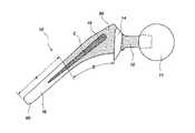
- FIG. 1is a side view of a prosthetic femoral implant, specifically illustrating a collar portion, a modular neck portion, and a stem portion having a plurality of surficial zones, each zone having a roughness, made in accordance with the principles of the present invention
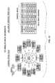
- FIG. 2is a top view of the prosthetic femoral implant of FIG. 1 , specifically illustrating a top surface of the collar portion, with the modular neck portion removed, having a cavity formed therein, made in accordance with the principles of the present invention;
- FIG. 3is a bottom view of the modular neck portion, which has an indexable portion shaped to correspond with the cavity formed in the top of the collar, made in accordance with the principles of the present invention
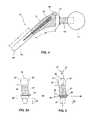
- FIG. 4is a side view of a prosthetic femoral implant, similar to FIG. 1 , illustrating a femoral head portion of the prosthetic femoral implant attached to the modular neck portion and the stem portion, made in accordance with the principles of the present invention;
- FIG. 5is a side view of one embodiment of the modular neck portion made in accordance with the principles of the present invention.
- FIG. 5Ais a side view of an alternative embodiment of the modular neck portion made in accordance with the principles of the present invention.
- FIG. 6is a schematic view of a human pelvis illustrating the natural placement of the femur within the hip joint, and the naturally occurring lateral offset of the femur within the hip joint;
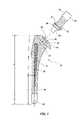
- FIG. 7is an exploded side view of the prosthetic implant illustrating the head portion, the modular neck portion and the stem portion of the implant, made in accordance with the principles of the present invention
- FIG. 8is an enlarged side view of the prosthetic implant illustrating the lateral offset and the vertical drop of a head and neck combination
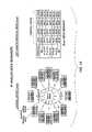
- FIGS. 9 through 11are illustrations representing several examples of the lateral offset and the vertical drop as illustrated in FIG. 8 using an anteversion angle of eight degrees in the modular neck portion;
- FIGS. 12 through 14are illustrations representing several examples of the lateral offset and the vertical drop as illustrated in FIG. 8 using an anteversion angle of twelve degrees in the modular neck portion.
- a “focal point,” referred to as item 15may be defined as a point of convergence of two axes, namely a long axis, represented by the line Y, of a femoral stem portion 16 of a prosthetic implant 10 , and a neck axis, represented by the line Z′, of the prosthetic implant 10 .
- the phrase “lateral offset”refers to the horizontal distance relative to a patient in a standing position from the center of the pelvis to the center of the femoral canal in the natural hip joint.
- lateral offsetrefers to the horizontal distance between a center 11 a of a ball or femoral head portion 11 of the implant 10 and the long axis Y of the femoral stem portion 16 of the implant 10 .
- vertical droprefers to the vertical distance between the center 11 a of the head portion 11 and the focal point 15 .
- Designers of hip stem prosthesesmay choose to increase the lateral offset by increasing or decreasing the distance between a center of the ball or femoral head of the implant and the mid-line, or long axis, of the femur in order to aid in the restoration of the biomechanics of the natural hip joint, as illustrated in FIG. 6 .
- An increased lateral offsetoperates to increase the torsional forces that are exerted on the femoral implant, and such forces become applied to the cement-implant interface between the implant and the medullary canal of the femur. There is therefore, in cases of an increased lateral offset, an increased need for torsional stability to prevent the implant from loosening from the bone or cement.
- torsional forcesmay be more effectively opposed by applying a type of differential porosity to the surface of a femoral implant, to resist the torsional forces.
- the femoral implantmay be more effectively tuned or adjusted after implantation of the femoral stem into the medullary canal of the femur, by selectively increasing or decreasing the lateral offset, and the version angle of the neck, using a modular neck component. In some instances, it is advantageous to adjust the lateral offset and the version angle simultaneously.
- FIGS. 1 and 7there is shown a side view of a femoral prosthetic implant designated generally at 10 , illustrated with a medial side of the implant 10 facing downward in FIG. 1 and to the right in FIG. 7 .
- the femoral prosthetic implant 10comprises a substantially spherical femoral head 11 (illustrated best in FIGS. 4 and 7 ), which may be attached to a modular indexable neck portion 12 for use as the ball portion of a ball and socket joint, a collar portion 14 , a stem portion 16 comprising a proximal stem region 50 and a distal stem region 60 , and a teardrop-shaped depression 18 located between the proximal stem region 50 and the distal stem region 60 .
- the above componentsmay be manufactured from titanium for cementless stem applications and from cobalt chrome molybdenum alloy in cemented stem applications for interfacing with cement and for providing less risk of fretting and corrosion at the modular stem neck junction. It should be noted that other material may be used that are presently known, or which may become known, in the art for manufacturing the above components, which can be readily determined by one of skill in the art. Each of the above components will be more particularly described below in relation to FIGS. 1 , 4 and 7 .
- fixation materialmay be defined as bone that may grow into the implant, bone cement that may interdigitate with the implant, or any other substance that one of skill in the art may use for securing the implant to the bone to inhibit torsional loads that is presently known, or which may become known in the future, in the art without departing from the scope of the present invention.
- the present inventionis directed to utilize a prosthetic hip having an increased lateral offset between the spherical ball portion 11 , sometimes referred to herein as a head portion (illustrated in FIG. 4 ), of the prosthetic implant 10 and the shaft of the patient's femur (illustrated best in FIG. 6 ).
- a head portionillustrated in FIG. 4
- any suitable head portion 11which may be substantially spherical in shape, either presently known in the art, or which may become known in the future, may be utilized by the present invention as the ball portion of the ball and socket joint.
- the head portion 11may be configured for articulating with an articulation surface, which articulation surface may be an acetabular cup or other surface used to assemble the socket portion of a ball and socket joint.
- the head portion 11may be modular and attached to the neck portion 12 by a taper lock as illustrated in FIG. 4 , or the head portion 11 may alternatively be integral with the neck portion 12 (not illustrated in the figures).
- the present inventionmay also utilize a modular neck portion 12 to create the lateral offset required to aid in restoring the natural biomechanics of the joint.
- the natural biomechanics of the hip jointis demonstrated in FIG. 6 .
- neck portion 12may be adjusted by a surgeon after the prosthetic implant 10 has been implanted within the femur, by changing the orientation of the neck portion 12 to any one of a plurality of differing positions as illustrated in FIG. 2 . Although there are twelve such positions shown in FIG. 2 , it is to be understood that the implant 10 may be designed to accommodate more or fewer than twelve such selectable positions.
- Neck portion 12may be replaced with various sizes of necks 12 , for example by a longer neck or shorter neck than that shown in the figures, with the size of the neck depending upon the need of the patient.
- the neck sizemay be determined by the surgeon at the time of surgery.
- the length of the neck portion 12may be configured and dimensioned to correspond with the increased need for lateral offset.
- Some exemplary lengths of the modular neck portion 12include 32 mm, 35 mm, and 38 mm. It should be noted that any size neck portion 12 may be used to increase the lateral offset and one of skill in the art could modify the length of the neck portion 12 to match the varying needs and anatomies of each individual patient.
- the neck portion 12comprises a proximal end 30 and a distal end 31 .
- the proximal end 30comprises a smooth surface 32 that may have a slightly tapered outer edge 33 such that the proximal end 30 may matingly engage a matching opening located within the head portion 11 such that the head portion may be secured to the neck portion 12 as illustrated in FIG. 4 .
- one of skill in the artmay modify the shape of the tapered outer edge 33 to increase or decrease the taper angle or to be of any shape, including no taper, presently known, or which may become known, in the art to secure the neck portion 12 to the head portion 11 .
- the above structural featuresmay be referred to herein as a means for attaching the indexable neck portion to the head portion.
- the head portion 11may alternatively be integrally attached to the neck portion 12 without departing from the scope of the present invention.
- a long axis of the neck portion 12may be defined as being normal to a plane 35 of the base of the neck portion 12 .
- An angle ⁇also referred to herein as an anteversion angle ⁇ , is also illustrated in FIG. 5 , and may be defined as the angle between the reference axis Z and an anteverted axis, also referred to herein as the neck axis, represented by the line Z′.
- the angle ⁇ of the neck portion 12permits the head portion 11 to be located either farther anteriorly, or farther posteriorly within the hip joint.
- Exemplary anteversion angles ⁇may be between the range of about zero and about twelve degrees. It should be noted that one of skill in the art could modify the anteversion angle ⁇ without departing from the scope of the present invention such that the anteversion angle ⁇ could be greater than twelve degrees, depending upon the need of the patient and the desired result.
- the neck portion 12further comprises a shaft 34 separating the proximal end 30 from the distal end 31 .
- the neck portion 12comprises a raised portion 36 located near the base of the shaft 34 on the distal end 31 , positioned at an angle with respect to the neck axis Z′ creating the anteversion of the neck portion 12 as illustrated most clearly in FIGS. 5 and 5A , and discussed above. It should be noted that one of skill in the art may modify the angle of the raised portion 36 to increase or decrease the anteversion angle ⁇ or may reposition the raised portion 36 to any position presently known, or which may become known, in the art to create an anteversion in the neck portion 12 . It should further be noted that one of skill in the art could modify the current invention without departing from the scope of the present invention so as to eliminate the raised portion 36 completely, and simply angle the shaft 34 of the neck portion 12 to the desired anteversion angle ⁇ .
- the surface of the shaft 34 and the distal end 31 of the neck portion 12may contain a roughness as illustrated in FIGS. 5 and 5A . It should be noted that one of skill in the art may modify the surface of the neck portion 12 such that the roughness may be increased to an even rougher surface, or such that the neck portion 12 may be smooth, instead of rough, without departing from the scope of the present invention.
- the distal end 31 of the modular neck portion 12may comprise an indexable portion extending therefrom.
- the distal end 31may also comprise a first tapered portion 38 disposed thereon, sometimes referred to herein as a first insert, and may further comprise a second tapered portion 39 , sometimes referred to herein as a second insert, extending below and being disposed on the first tapered portion 38 .
- This combination of tapersmay be referred to herein as a double taper.
- One embodiment of the first tapered portion 38includes a geared section 21 illustrated in FIG. 5 comprising a plurality of male gears 37 for matingly engaging a corresponding female geared section 21 of the stem portion 16 .
- the male gears 37may be tapered as it is a part of the first tapered portion 38 .
- the male gears 37function to act in concert with the female geared section 21 of the stem portion 16 permitting the modular neck portion 12 to be indexed in a plurality of positions and orientations, thus altering the angle of anteversion with respect to the stem portion 16 and permitting the surgeon the ability to fine tune and adjust the modular neck portion 12 such that the stress points may be altered or shifted.
- first tapered portion 38comprises a taper without gears and may be fashioned as illustrated in FIG. 5A .
- first tapered portion 38may be modified by one of skill in the art to be of any length, either larger or smaller than illustrated in FIGS. 5 and 5A , presently known, or which may become known in the future, in the art for securing the neck portion 12 to the stem portion 16 , and may further be modified to increase or decrease the angle of taper without departing from the scope of the present invention.
- the second tapered portion 39extends below the first tapered portion 38 and may be between the range of about two to about five times the length of the first tapered portion 38 . It should be noted that the length of the second tapered portion 39 may be modified, as illustrated in FIGS. 5 and 5A , by one of skill in the art to provide a taper that does not bottom out and provides a secure connection between the neck portion 12 and the stem portion 16 . For example, FIG. 5 illustrates one embodiment of the second tapered portion as being longer than an alternative embodiment of the second tapered section 39 illustrated in FIG. 5A .
- the second tapered portion 39functions to provide a primary self-locking taper for locking and securing the neck portion 12 to the stem portion 16 .
- the first tapered portion 38functions as a secondary locking taper to secure the neck portion 12 to the stem portion 16 , and may act as an emergency backup to maintain the connection between the neck portion 12 and a cavity 20 such that the stem portion 16 does not separate from the rest of the prosthetic implant 10 , should the primary locking taper fail for any number of reasons.
- the first scenariorelates to the patient's anatomy where the stem portion 16 cannot be surgically placed in an upright orientation with respect to the medullary canal of the femur (not shown), causing a skewed orientation of the implant 10 .
- the second scenariooccurs when the surgical technique of the surgeon results in less than perfect orientation of the stem portion 16 within the medullary canal of the femur (not illustrated). In either scenario the result is the same, the orientation of the stem portion 16 is not aligned with the shaft of the femur causing pain and discomfort to the patient as well as reducing the longevity of the implant, which will loosen over time due to the differing forces placed on the implant.
- the present inventionpermits the surgeon during surgery to fine tune and adjust the orientation of the stem with the shaft of the femur by replacing one neck portion 12 with another to create the desired lateral offset and create the desired orientation for each individual patient.
- One solutionis explained below in connection with the differential porosity, or roughness, of the stem portion 16 .
- the stem portion 16may be designed such that it may aid in the restoration of the natural joint mechanics and for allowing the surgeon a final opportunity to correct for malpositioning of implants 10 due to surgical technique and bone deformity.
- the proximal stem 50may contain collar portion 14 configured with a cavity 20 where a self-locking taper and a positive indexing mechanism may be employed to ensure that the proper head, length, version and offsets may be obtained.
- This unique designmay feature provides a plurality of self-locking positions providing several combinations of neck length version and offset for closely aiding in the restoration of the natural hip joint mechanics.
- This innovative designprovides the surgeon with the opportunity to intervene at the last possible surgical moment and fine tune the hip joint mechanics without disruption of the implant-cement-bone interface.
- the design of the stem portion 16provides for increased opportunity to surgically intervene for certain post-operative complications, for example, component malposition, leg length discrepancy, dislocations and replacement of bearing surfaces, with minimal disruption of the interfaces of the bone.
- FIG. 2illustrates a top view of the collar portion 14 having a cavity 20 formed therein.
- a first sidewall 40defining a first portion 41 having twelve different positions denoted by numerals 0 - 11 situated in a similar position as a standard clock.
- the differing orientationsmay be established by a female geared section 21 , which permits the neck portion 12 to have differing version angles with respect to the stem portion 16 , which may be adjusted by removing the neck portion 12 from the cavity 20 and rotating the neck portion 12 to the desired orientation creating the desired version angle.
- the female geared section 21 of the cavity 20may be configured and dimensioned with slight protrusions 22 extending inwardly into the cavity 20 from the first sidewall 40 creating a plurality of female gears to matingly engage the male gears 37 of the modular neck portion 12 for adjusting the orientation of said modular neck portion 12 .
- FIG. 3illustrates the corresponding bottom portion of the modular neck portion 12 having male gears 37 with mating protrusions 24 for mating with the female gear section and may be spaced between protrusions 22 such that the two arrays of protrusions mate with one another forming a matching fit.
- Mating protrusions 24function similarly to protrusions 22 in that the mating protrusions 24 permit the modular neck portion 12 to be adjusted into twelve differing version angles. It should be noted that the number of protrusions and gears may be modified by one of skill in the art to include more or less than twelve differing positions in which the neck may be oriented such that differing version angles may be achieved.
- protrusions 22 or female gearsFor example, by removing two protrusions 22 or female gears from the cavity 20 and removing the same number of corresponding mating protrusions 24 or male gears 37 from the first tapered portion 38 , ten different positions may be achieved instead of twelve. The same relationship holds true for adding protrusions 22 or female gears and mating protrusions 24 or male gears 37 .
- a second sidewall 42 within the cavity 20defines a second portion 43 that may be tapered to match the taper of the second tapered portion 39 of the modular neck portion 12 such that a secure lock may be achieved between the stem portion 16 and the modular neck portion 12 .
- the taper of the second portion 43may be of the self-locking type and provides for the primary fixation of the stem portion 16 to the neck portion 12 .
- the depth of the second portion 43may be dimensioned such that the second portion 43 may be deep enough to avoid “bottoming out” of the taper, ensuring that the self-locking taper may occur.
- first tapered portion 38 of the modular neck portion 12may be configured for matingly engaging the first portion 41 of the cavity 20 forming a secondary lock or fixation
- second tapered portion 39 of the modular neckmay be configured for matingly engaging the second portion 43 of the cavity 20 forming a primary lock or fixation of the self-locking type.
- the above structural featuresmay be referred to herein as a means for attaching the indexable neck portion to the stem portion.
- the collar portion 14may be disposed on the stem portion 16 by extending from the proximal region 50 of the stem portion 16 in a medial, anterior and posterior direction creating a broad, full collar portion 14 .
- the broad, full collari.e. more than just a medial collar
- the force created by the full collar portion 14provides for optimal/complete interdigitation of the cement with the bone as well as with the implant. Therefore, the collar portion 14 functions to force cement into the medullary canal of the femur as well as into the porous depressions on the surface of the prosthetic implant.
- the collar portion 14functions as a cap to cover the medullary canal such that wear debris generated from the prosthetic implant may be prevented from migrating into the medullary canal.
- the stem portion 16which may be configured and dimensioned to be surgically located within the medullary canal of the femur.
- the stem portion 16comprises a proximal region 50 , a distal region 60 and a depression 18 located between the proximal region 50 and the distal region 60 .
- the depression 18may be defined by a boundary with the boundary defining the overall shape of the depression.
- the stem portion 16may be divided into multiple separate and distinct zones, each zone having its own unique surface porosity or roughness, thereby creating a differential porosity or differential roughness.
- FIGS. 1 and 4illustrate three zones of differing porosity or roughness, zone A, zone B and zone C.
- the first zonecomprises the distal stem 60 and may be configured and dimensioned with either a very slight porous surface or with no porous surface at all creating a smooth surface.
- the second zonesubstantially comprises the proximal stem 50 and may be configured and dimensioned with a porous surface that is rougher than zone A.
- the third zonedesignated as C, comprises a teardrop-shaped depression 18 that may be configured and dimensioned with an even rougher porous surface than zone B and provides increased torsional stability for the implant 10 . Therefore, zone A has the smoothest surface, zone B has a rougher surface than zone A and zone C has the roughest surface of all three zones, creating a tripartite differential porosity or roughness.
- zones B and Cprovide surfaces to which either the bone may interdigitate with and grow into more effectively, or to which the bone cement may adhere to more effectively to thereby secure the implant 10 to the medullary canal of the femur.
- the smooth surface of zone Aprovides a surface that bone and cement will not adhere to as effectively, such that the distal portion 60 of the stem portion 16 will be more easily removable from the medullary canal of the femur, should removal of the implant 10 become necessary.
- the benefit of the tripartite differential porosity or roughnessis an increased torsional stability in the connection between the stem portion 16 and the femur, at the posterior and anterior sides of the prosthesis, but not on the medial or lateral sides of the prosthesis, such that abrasion wear is not increased on the medial side.
- Such a differential roughnessmay sometimes be referred to herein as a means for resisting torsional loads.
- the distal portion 60 of the stem portion 16 or zone Amay have a finish that has a polished finish between the range of 2-15 RA.
- the proximal portion 50 of the stem portion 16 or zone Bmay have a rougher satin finish between the range of 15-30 RA.
- the depression 18may have an enhanced satin polish that may be between the range of 30-80 RA, which is rougher than the proximal portion's 50 satin finish.
- zones A, B and Cmay each be modified, such that the area of the implant 10 that each zone includes may be increased or decreased.
- FIG. 1illustrates the zones A, B and C, with zone A being roughly the same length on the stem as zone B.
- zone Amay be shortened to include the area covered by zone A′, thus decreasing the area of zone A while increasing the area of zone B to include the area covered by zone B′.
- FIG. 1that one of skill in the art may modify the area of each zone to include a larger or smaller area and thus proportionally increasing or decreasing the amount of surficial roughness present in a given zone.
- the stem portion 16may include roughness depressions 18 of any suitable shape.
- the stem portion 16may include a single teardrop-shaped depression 18 , or the stem portion 16 may alternatively comprise two opposing teardrop-shaped depressions 18 .
- Teardrop-shaped depressions 18may be located on the anterior and posterior portions of the stem portion 16 and may extend from a proximal stem region 50 into a distal stem region 60 .
- the depressions 18may be located on the anterior and posterior portions and aid in securing the stem portion 16 to the implant-bone cement interface, and which functions to oppose the torsional forces experienced in the hip joint.
- the depression(s) 18 located on either the anterior portion, the posterior portion or on both portions of the stem portion 16may be a single depression or may be a series of multiple depressions effectuating a single depression 18 .
- the porosity or roughness of the depression 18may fill the entire depression 18 or may fill only a portion of the depression 18 , depending upon the desired result.
- FIGS. 1 and 4illustrate the depression 18 having a boundary defining the depression 18 or recessed surface, in which the boundary of the depression 18 is the same as the boundary of the porosity or roughness.
- the surface of the depression 18provides for increased interdigitation between the implant 10 and the cement or bone and causes the implant 10 to have an increased ability to resist the increased torsional loads placed on the implant 10 responsive to the increase in lateral offset and version angle, both of which create an increased need for torsional resistance.
- the size of the teardrop-shaped depression 18may be modified to be of any suitable size and accomplish the same results.
- depression(s) 18has been illustrated as teardrop-shaped, one of skill in the art may modify the shape of the depression 18 to be of any shape presently known, or which may become known, in the art to inhibit torsional forces.
- the surface of the stem portion 16may contain a roughness as illustrated in FIGS. 1 and 4 .
- the roughnessmay be comprised of a material such as beads that have been bead blasted onto the surface of the stem portion 16 such that the surface area of the stem portion 16 may be increased for increasing the interdigitation between the bone, the implant 10 and the bone cement such that a more secure fixation of the implant 10 to the bone may be achieved.
- the method of applying the surficial roughness to the stem portion 16may be modified by one of skill in the art using a method presently known, or which may become known in the future, in the art for adding a surficial roughness to the stem portion 16 .
- the material, design and shape used to create the roughnessmay be modified by one of skill in the art using any suitable material, design and shape presently known, or which may become known, in the art for increasing the surface area and interdigitation of the stem portion 16 .
- zone Ahas the smoothest surface and has less surface area than both zone B and zone C.
- the reason for the decreased surface areais in large part due to the fact that it is difficult to remove the distal stem 60 from the femoral bone once the stem portion 16 has been implanted into the femur and that difficulty is increased when the surface area of the distal stem 60 is increased.
- the strength of the bond between the bone fixation material and the distal stem 60also increases and becomes extremely difficult to remove the implant 10 from the bone should it become necessary to remove the implant 10 for revision surgery. Removal becomes extremely difficult because there is no technique available, barring drastic resection, for the surgeon to get instrumentation into the distal portion of the femur that permits the surgeon to sufficiently loosen and remove the implant 10 .
- Zone Bcomprising the proximal stem 50
- the surficial roughness and hence the surface area of the proximal stem 50may be increased because the proximal stem 50 is more readily accessible to the surgeon as the surgeon may use instrumentation to pry the stem and ultimately the implant 10 from the bone.
- the increased roughness in zone Bis advantageous because it increases the bonding strength, which results in greater stabilization of the implant 10 within the femur.
- Zone Ccomprising the depression 18
- Zone Cmay contain the greatest roughness and results in the greatest surface area of all three zones. Therefore, there is a large amount of interdigitation between the fixation material and the depression 18 , which results in great bonding strength. Additionally, because the depression or depressions are located on the anterior and posterior portions of the stem portion 16 the increased roughness and surface area of the depressions 18 operate to oppose the increased torsional forces that are experienced as the natural biomechanics of the femur are simulated by increasing the lateral offset and version angle of the modular neck portion 12 .
- the differential roughness of the present inventionadvantageously utilizes unique, novel design features that increase resistance to torsional forces.
- the depression 18while increasing the bonding strength and hence resisting torsional forces, may be used as a part of a mechanism to break the bond between the fixation material and the implant 10 .
- an instrument(not shown in the figures) may be used to initially uncover the proximal most portion of the depression 18 .
- the instrumentmay be used to break the bond by following the depression 18 , which acts as a channel or guide for the instrument, loosening the implant 10 from the fixation material.
- FIG. 8wherein an enlarged side view of the proximal portion of the femoral prosthetic implant 10 with the neck portion 12 and the head portion 11 secured to the stem portion 16 .
- the lateral offset between a center 11 a of the head portion 11 and the mid-line or longitudinal axis, represented by the line Y, of the femoral implant 10is illustrated along with the corresponding vertical drop associated with the size of the modular neck portion 12 and head portion 11 to be used.
- the vertical dropmay be determined as the vertical distance between the center 11 a of the head portion 11 of the implant 10 and the intersection of the longitudinal axis Y and a neck axis Z′ at the focal point 15 .
- the neck axis Z′runs through the center 11 a of the head portion 11 and extends through the neck portion 12 .
- the lateral offset as well as the vertical dropwill also change accordingly.
- the lateral offsetwill necessarily increase as the center 11 a of the head portion 11 is positioned farther away from the longitudinal axis Y, thus changing the vertical drop as well.
- the center 11 a of the head portion 11is brought closer to the longitudinal axis Y, reducing the lateral offset as well as the vertical drop.
- FIGS. 9-14wherein specific examples of how the size of the femoral head portion 11 and size of the neck portion 12 affect the lateral offset and vertical drop of the implant 10 .
- FIGS. 9-14are intended as illustrative examples only, and are not intended to be limiting of the scope of the present invention.
- FIGS. 9-11use an eight degree anteversion angle ⁇ in the neck portion 12
- FIGS. 12-14use a twelve degree anteversion angle ⁇ in the neck portion 12
- FIG. 9utilizes a 32 mm neck portion 12
- FIG. 10utilizes a 35 mm neck portion 12
- FIG. 11utilizes a 38 mm neck portion 12
- the same sizes of neck portions 12are also used in the illustrations of FIGS. 12-14 .
- FIG. 9utilizes a neck portion 12 having an anteversion angle ⁇ equal to eight degrees, and the neck portion 12 is 32 mm in length.
- the collar portion 14is illustrated as having twelve positions numbered 0 - 11 .
- Position number 11will now be used to demonstrate how the charts may be read.
- the neck portion 12When the neck portion 12 is located in position number 11 , the neck portion 12 has a four degree anteversion angle ⁇ .
- the small chart associated with position number 11represents the femoral head size and the associated lateral offset.
- the lateral offsetmay also be increased or decreased as noted in the chart.
- a +5 mm femoral headwill have a corresponding lateral offset of 46 mm.
- the +5 mm femoral head located in position number 11will also correspond to a 41 mm vertical drop. Therefore, as demonstrated above, as the length of the neck portion 12 or the size of the femoral head changes, the corresponding lateral offset and associated vertical drop will also change accordingly. It should be noted that the remaining position numbers may be referred and interpreted in like manner as position number 11 demonstrated above.
- the surgeonWhen using an integral neck, the surgeon is required to implant the acetabular cup and its component parts into the acetabulum and then attach the femoral head to the acetabular cup prior to implanting the femoral component of the prosthesis into the exposed femoral canal. Implanting the acetabular components typically takes approximately thirty minutes for a surgeon to complete. Thus, while the surgeon is preparing the acetabulum and securing the acetabular cup and other components therein, the resected proximal femur remains exposed and continues to bleed. The result is often an unnecessary loss of blood between the range of 200-400 cc in volume.
- the modularity of the neck portion 12 of the present inventionpermits the surgeon to resect the proximal femur, expose and otherwise prepare the femoral canal and then implant the stem portion 16 of the prosthetic implant 10 promptly into the femoral canal without having to wait for the surgeon to implant the acetabular cup and its component parts into the acetabulum, which reduces excessive bleeding in the femur.
- the implantation of the stem portion 16 into the femoral canalacts similarly to a plug being inserted into a hole to stop a leak, and thereby reduces excessive bleeding in the femur.
- the surgeonmay proceed with the implantation of the acetabular components without unnecessary blood loss in the femur.
- the surgeonmay attach the modular neck portion 12 to the implanted components and finish the remainder of the surgery.
- Another advantageous feature of the present inventionmay be realized during the unfortunate occurrence of a revision surgery to replace damaged components or for any other reason a revision surgery may be necessary.
- a prosthetic device having an integral neckhas been surgically implanted on a previous occasion, and it becomes necessary for the surgeon to replace the acetabular cup on the socket side of the joint by implanting a bone graft, there is a high risk of damaging the femoral component of the prosthetic implant 10 .
- the head portion 11 and the neck portion 12are connected to the acetabular cup in the acetabulum and may get in the way during removal, making it difficult to remove the acetabular cup without damaging the femoral component.
- the only other option for the surgeon, besides potentially damaging other componentsis to try to avoid the integral neck. However, such avoidance compromises the quality of the surgical procedure.
- the modularity of the neck portion 12 of the present inventionadvantageously permits the surgeon to detach the modular neck portion 12 from the remainder of the implant 10 .
- the surgeonmay expose the needed area to perform the revision surgery and then reattach the modular neck portion 12 without the need to remove the stem portion 16 from the femur and posing a risk of damaging the femur or the stem portion 16 .
- An additional advantageous feature of the modular neck portion 12 of the present inventionmay be realized in a revision surgery when the previously implanted stem and neck are chrome cobalt or other metallic material, but the prosthetic femoral head is ceramic. It is a contra-indication to take a ceramic femoral head off and then reattach it again to the neck in the original circumferential grip friction-pressure fit, because the ceramic can split or crack at the tapered connection by the inherent stress riser that exists in a friction fit involving a circumferential grip. Therefore, using the integral necks of the prior art causes the surgeon to replace the entire femoral component in order to avoid refitting and possibly splitting the ceramic head, which requires further resection of the femur.
- the surgeoncan simply replace the entire head and neck combination without having to remove the stem portion 16 by simply detaching the neck 12 from the stem 16 . Therefore, the contra-indication of ceramic is avoided without removing the stem portion 16 of the implant 10 from the femur, which eliminates unnecessary bone resection.
- a useful method of attaching a prosthetic femoral implant to a patient's femurincludes the steps of:
- a femoral prosthetic implanthaving a modular neck, a full collar, and stem, said stem comprising a proximal portion, a distal portion and a teardrop-shaped depression, each portion of the stem being separate and having distinct porosity creating a tripartite differential porosity surface, into the bone cement;
Landscapes
- Health & Medical Sciences (AREA)
- Orthopedic Medicine & Surgery (AREA)
- Cardiology (AREA)
- Oral & Maxillofacial Surgery (AREA)
- Transplantation (AREA)
- Engineering & Computer Science (AREA)
- Biomedical Technology (AREA)
- Heart & Thoracic Surgery (AREA)
- Vascular Medicine (AREA)
- Life Sciences & Earth Sciences (AREA)
- Animal Behavior & Ethology (AREA)
- General Health & Medical Sciences (AREA)
- Public Health (AREA)
- Veterinary Medicine (AREA)
- Prostheses (AREA)
Abstract
Description
Claims (2)
Priority Applications (10)
| Application Number | Priority Date | Filing Date | Title |
|---|---|---|---|
| US10/244,149US7323013B2 (en) | 1998-04-14 | 2002-09-13 | Differential porosity prosthetic hip system |
| US10/405,065US20040010319A1 (en) | 1998-04-14 | 2003-03-31 | Intrinsic stability in a total hip stem |
| PCT/US2003/011603WO2003086244A1 (en) | 2002-04-12 | 2003-04-14 | Differential porosity prosthetic hip system |
| AU2003230928AAU2003230928A1 (en) | 2002-04-12 | 2003-04-14 | Differential porosity prosthetic hip system |
| KR1020047016344AKR20050026381A (en) | 2002-04-12 | 2003-04-14 | Differential porosity prosthetic hip system |
| US11/589,037US20070043448A1 (en) | 1998-04-14 | 2006-10-26 | Intrinsic stability in a total hip stem |
| US11/589,013US20070043446A1 (en) | 1998-04-14 | 2006-10-26 | Differential porosity prosthetic hip system |
| US12/022,068US20080183298A1 (en) | 2002-04-12 | 2008-01-29 | Differential Porosity Prosthetic Hip System |
| US14/245,896US20150039096A1 (en) | 2002-04-12 | 2014-04-04 | Differential porosity prosthetic hip system |
| US14/247,077US20150039093A1 (en) | 2002-04-12 | 2014-04-07 | Differential porosity prosthetic system |
Applications Claiming Priority (4)
| Application Number | Priority Date | Filing Date | Title |
|---|---|---|---|
| US5969898A | 1998-04-14 | 1998-04-14 | |
| US09/505,876US6464728B1 (en) | 1998-04-14 | 2000-02-17 | Modular neck for femur replacement surgery |
| US37239002P | 2002-04-12 | 2002-04-12 | |
| US10/244,149US7323013B2 (en) | 1998-04-14 | 2002-09-13 | Differential porosity prosthetic hip system |
Related Parent Applications (2)
| Application Number | Title | Priority Date | Filing Date |
|---|---|---|---|
| US5969898AContinuation-In-Part | 1998-04-14 | 1998-04-14 | |
| US09/505,876Continuation-In-PartUS6464728B1 (en) | 1998-04-14 | 2000-02-17 | Modular neck for femur replacement surgery |
Related Child Applications (5)
| Application Number | Title | Priority Date | Filing Date |
|---|---|---|---|
| US10/405,065Continuation-In-PartUS20040010319A1 (en) | 1998-04-14 | 2003-03-31 | Intrinsic stability in a total hip stem |
| US11/589,013ContinuationUS20070043446A1 (en) | 1998-04-14 | 2006-10-26 | Differential porosity prosthetic hip system |
| US11/589,037Continuation-In-PartUS20070043448A1 (en) | 1998-04-14 | 2006-10-26 | Intrinsic stability in a total hip stem |
| US89796407AContinuation-In-Part | 2002-04-12 | 2007-08-30 | |
| US12/022,068ContinuationUS20080183298A1 (en) | 2002-04-12 | 2008-01-29 | Differential Porosity Prosthetic Hip System |
Publications (2)
| Publication Number | Publication Date |
|---|---|
| US20030074079A1 US20030074079A1 (en) | 2003-04-17 |
| US7323013B2true US7323013B2 (en) | 2008-01-29 |
Family
ID=29254192
Family Applications (4)
| Application Number | Title | Priority Date | Filing Date |
|---|---|---|---|
| US10/244,149Expired - Fee RelatedUS7323013B2 (en) | 1998-04-14 | 2002-09-13 | Differential porosity prosthetic hip system |
| US11/589,013AbandonedUS20070043446A1 (en) | 1998-04-14 | 2006-10-26 | Differential porosity prosthetic hip system |
| US12/022,068AbandonedUS20080183298A1 (en) | 2002-04-12 | 2008-01-29 | Differential Porosity Prosthetic Hip System |
| US14/245,896AbandonedUS20150039096A1 (en) | 2002-04-12 | 2014-04-04 | Differential porosity prosthetic hip system |
Family Applications After (3)
| Application Number | Title | Priority Date | Filing Date |
|---|---|---|---|
| US11/589,013AbandonedUS20070043446A1 (en) | 1998-04-14 | 2006-10-26 | Differential porosity prosthetic hip system |
| US12/022,068AbandonedUS20080183298A1 (en) | 2002-04-12 | 2008-01-29 | Differential Porosity Prosthetic Hip System |
| US14/245,896AbandonedUS20150039096A1 (en) | 2002-04-12 | 2014-04-04 | Differential porosity prosthetic hip system |
Country Status (4)
| Country | Link |
|---|---|
| US (4) | US7323013B2 (en) |
| KR (1) | KR20050026381A (en) |
| AU (1) | AU2003230928A1 (en) |
| WO (1) | WO2003086244A1 (en) |
Cited By (22)
| Publication number | Priority date | Publication date | Assignee | Title |
|---|---|---|---|---|
| US20080183298A1 (en)* | 2002-04-12 | 2008-07-31 | Encore Medical, L.P. | Differential Porosity Prosthetic Hip System |
| US20110190907A1 (en)* | 2010-02-01 | 2011-08-04 | Biomet Manufacturing Corp. | Transdermal Intraosseous Device |
| US20110202140A1 (en)* | 2010-02-12 | 2011-08-18 | University Of Washington | Load bearing implants with engineered gradient stiffness and associated systems and methods |
| US20120010722A1 (en)* | 2009-09-01 | 2012-01-12 | Concept, Design And Development, Llc | Neck sparing total hip implant system |
| US20120253468A1 (en)* | 2009-10-22 | 2012-10-04 | Depuy International Limited | Medical implant device |
| US8915970B2 (en) | 2013-02-08 | 2014-12-23 | Biomet Manufacturing, Llc | Transdermal prosthesis |
| US8968415B2 (en) | 2012-02-07 | 2015-03-03 | Biomet Manufacturing, Llc | Implant fixation device |
| US8992531B2 (en) | 2011-12-16 | 2015-03-31 | Chow Ip, Llc | Prosthetic femoral stem for use in high impact hip replacement |
| US20150196397A1 (en)* | 2014-01-14 | 2015-07-16 | Kyocera Medical Corporation | Artificial hip joint stem and artificial hip joint including the same |
| US9101496B2 (en) | 2011-11-30 | 2015-08-11 | Zimmer, Inc. | Ultrasonic orthopedic taper dissociation device and method |
| US20150366668A1 (en)* | 2014-06-23 | 2015-12-24 | Community Blood Center | Cellular-scale surface modification for increased osteogenic protein expression |
| US9301765B2 (en) | 2011-12-16 | 2016-04-05 | Chow Ip, Llc | Prosthetic femoral stem for use in high offset hip replacement |
| AU2011371008B2 (en)* | 2011-06-14 | 2017-02-02 | Concept, Design And Development Llc | Neck sparing total hip implant system |
| US20180000598A1 (en)* | 2015-01-13 | 2018-01-04 | Imperial Innovations Limited | Hip stem |
| US10390975B2 (en) | 2012-09-10 | 2019-08-27 | Zimmer, Inc. | Transcutaneous implant for skeletal attachment of external prosthetic devices |
| USD901013S1 (en) | 2019-08-12 | 2020-11-03 | Ortho Development Corporation | Porous implant |
| USD901012S1 (en) | 2019-08-12 | 2020-11-03 | Ortho Development Corporation | Porous implant |
| USD901014S1 (en) | 2019-08-12 | 2020-11-03 | Ortho Development Corporation | Porous implant |
| US20220211506A1 (en)* | 2004-12-29 | 2022-07-07 | DePuy Synthes Products, Inc. | Method of Preparing Joint Prosthesis With Infinitely Positionable Head |
| US11498124B1 (en) | 2019-11-25 | 2022-11-15 | Ortho Development Corporation | Method for sintering porous structures from powder using additive manufacturing |
| US11565021B1 (en) | 2019-08-12 | 2023-01-31 | Ortho Development Corporation | Composite structure porous implant for replacing bone stock |
| US12434302B2 (en) | 2019-11-25 | 2025-10-07 | Ortho Development Corporation | Method for manufacturing porous structures using additive manufacturing |
Families Citing this family (58)
| Publication number | Priority date | Publication date | Assignee | Title |
|---|---|---|---|---|
| US7189261B2 (en)* | 1998-04-03 | 2007-03-13 | Smith & Nephew, Inc. | Modular humeral prosthesis and method |
| US7597715B2 (en) | 2005-04-21 | 2009-10-06 | Biomet Manufacturing Corp. | Method and apparatus for use of porous implants |
| US8123814B2 (en) | 2001-02-23 | 2012-02-28 | Biomet Manufacturing Corp. | Method and appartus for acetabular reconstruction |
| US6942699B2 (en) | 2001-07-11 | 2005-09-13 | Biomet, Inc. | Shoulder prosthesis |
| GB0207170D0 (en)* | 2002-03-26 | 2002-05-08 | Mcminn Derek J W | Hip joint prosthesis |
| US6866683B2 (en) | 2002-12-13 | 2005-03-15 | Medicine Lodge, Inc. | Modular implant for joint reconstruction and method of use |
| US6887276B2 (en)* | 2002-12-13 | 2005-05-03 | Medicine Lodge, Inc | Modular implant for joint reconstruction and method of use |
| US8821582B1 (en)* | 2003-05-27 | 2014-09-02 | Philip Scott Lyren | Hip implant with porous body |
| US20040243246A1 (en)* | 2003-05-27 | 2004-12-02 | Lyren Philip S. | Hip implant with porous body |
| US7534271B2 (en)* | 2004-01-22 | 2009-05-19 | Smith + Nephew | Femoral hip prosthesis and method of implantation |
| US20050203633A1 (en)* | 2004-03-02 | 2005-09-15 | Alfred Fernandes | Lifetime solution for hip dysfunction |
| US7135044B2 (en)* | 2004-03-09 | 2006-11-14 | Howmedics Osteonics Corp. | Modular prosthesis kits |
| US7547328B2 (en)* | 2004-05-26 | 2009-06-16 | Sidebotham Christopher G | Canine femoral stem system |
| GB2419291A (en)* | 2004-10-21 | 2006-04-26 | Biomet Uk Ltd | A femoral head prosthesis |
| US8266780B2 (en)* | 2005-04-21 | 2012-09-18 | Biomet Manufacturing Corp. | Method and apparatus for use of porous implants |
| US8066778B2 (en) | 2005-04-21 | 2011-11-29 | Biomet Manufacturing Corp. | Porous metal cup with cobalt bearing surface |
| US8048167B2 (en)* | 2005-08-30 | 2011-11-01 | Depuy Products, Inc. | Orthopaedic implant kit, orthopaedic surgery kit and associated method |
| US7578851B2 (en)* | 2005-12-23 | 2009-08-25 | Howmedica Osteonics Corp. | Gradient porous implant |
| US7806936B2 (en)* | 2006-10-19 | 2010-10-05 | Depuy Products, Inc. | Bowed femoral sleeve |
| EP2094197B8 (en) | 2006-12-07 | 2016-03-09 | IHip Surgical, LLC | Apparatus for total hip replacement |
| US8974540B2 (en) | 2006-12-07 | 2015-03-10 | Ihip Surgical, Llc | Method and apparatus for attachment in a modular hip replacement or fracture fixation device |
| US8579985B2 (en) | 2006-12-07 | 2013-11-12 | Ihip Surgical, Llc | Method and apparatus for hip replacement |
| KR100783190B1 (en)* | 2006-12-29 | 2007-12-07 | (주) 코리아나메디칼 | Hip joint stem |
| GB0702864D0 (en)* | 2007-02-14 | 2007-03-28 | Benoist Girard Sas | Prosthetic implant for use without bone cement |
| GB0705905D0 (en)* | 2007-03-28 | 2007-05-09 | Depuy Int Ltd | An Instrument for use in a joint replacement procedure |
| EP2139433B1 (en)* | 2007-04-28 | 2014-11-12 | DePuy International Limited | Determining the offset of the head part of an orthopaedic joint prosthesis stem component |
| EP2014260A1 (en)* | 2007-07-11 | 2009-01-14 | aap Implantate AG | Multi-part or modular orthopaedic and traumatological implant |
| US20100042213A1 (en) | 2008-08-13 | 2010-02-18 | Nebosky Paul S | Drug delivery implants |
| US10842645B2 (en) | 2008-08-13 | 2020-11-24 | Smed-Ta/Td, Llc | Orthopaedic implant with porous structural member |
| US20100042226A1 (en)* | 2008-08-13 | 2010-02-18 | Nebosky Paul S | Orthopaedic implant with spatially varying porosity |
| US9616205B2 (en) | 2008-08-13 | 2017-04-11 | Smed-Ta/Td, Llc | Drug delivery implants |
| JP5774989B2 (en) | 2008-08-13 | 2015-09-09 | スメド−ティーエイ/ティーディー・エルエルシー | Orthopedic screw |
| US9700431B2 (en) | 2008-08-13 | 2017-07-11 | Smed-Ta/Td, Llc | Orthopaedic implant with porous structural member |
| WO2010025386A1 (en) | 2008-08-29 | 2010-03-04 | Smed-Ta/Td, Llc | Orthopaedic implant |
| DE102008045291B4 (en) | 2008-09-02 | 2013-05-02 | Merete Medical Gmbh | Knee arthrodesis implant |
| US8066775B2 (en)* | 2009-06-12 | 2011-11-29 | Branovacki George | Joint implant |
| FR2956804B1 (en)* | 2010-03-01 | 2012-03-16 | C2F Implants | RANGE OF MODULAR ELEMENTS FOR THE CONSTITUTION OF A FEMALE HIP PROSTHESIS ROD |
| US8562690B1 (en) | 2010-04-22 | 2013-10-22 | Zimmer, Inc. | Modular revision femoral prosthesis |
| US8623093B2 (en) | 2010-07-07 | 2014-01-07 | Zimmer, Inc. | Sleeve for modular revision hip stem |
| WO2012015945A2 (en)* | 2010-07-29 | 2012-02-02 | Mayo Foundation For Medical Education And Research | Acetabular cup prosthesis |
| IT1401926B1 (en)* | 2010-09-14 | 2013-08-28 | Renzi Brivio | MODULAR PROSTHETIC DEVICE FOR THE REPLACEMENT OF THE HOOK ARTICLE. |
| DE202010008828U1 (en)* | 2010-10-18 | 2010-12-09 | Merete Medical Gmbh | Modular joint prosthesis system |
| US8597361B2 (en)* | 2010-11-11 | 2013-12-03 | Bioshift, Llc | Joint implant fixation system |
| US8702804B2 (en)* | 2011-12-02 | 2014-04-22 | Biomet Manufacturing, Llc | Variable prosthesis |
| ES2603562T3 (en)* | 2012-09-21 | 2017-02-28 | Waldemar Link Gmbh & Co. Kg | Joint implant |
| PL3054896T3 (en)* | 2013-10-13 | 2018-02-28 | 41Hemiverse Ag | Joint implant |
| CN104622602A (en)* | 2013-11-15 | 2015-05-20 | 中国石油天然气股份有限公司 | artificial femoral stem |
| CA2942523A1 (en)* | 2014-03-12 | 2015-09-17 | Encore Medical, L.P. | Femoral hip stem |
| US9597203B2 (en) | 2015-03-25 | 2017-03-21 | Tornier, Inc. | Modular humeral implant |
| CN106264797B (en)* | 2015-05-22 | 2018-02-02 | 嘉思特华剑医疗器材(天津)有限公司 | A kind of hip joint horizontal off set is precisely controlled structure |
| KR101696842B1 (en)* | 2015-09-24 | 2017-01-17 | 서강대학교산학협력단 | Desing method for neck of prosthesis on total hip replacement and the prosthesis |
| EP4252697A3 (en) | 2017-03-14 | 2024-03-27 | Stephen B. Murphy | Systems and methods for determining leg length change during hip surgery |
| JP1621250S (en)* | 2017-05-22 | 2018-12-25 | ||
| USD891615S1 (en)* | 2017-11-15 | 2020-07-28 | Joint Innovation Technogy, Llc | Revision stem |
| USD881395S1 (en)* | 2017-11-15 | 2020-04-14 | Joint Innovation Technology, Llc | Revision stem and ball |
| USD900317S1 (en)* | 2017-11-15 | 2020-10-27 | Joint Innovation Technology, Llc | Revision stem |
| USD895116S1 (en)* | 2017-11-15 | 2020-09-01 | Joint Innovation Technology, Llc | Revision stem and cup |
| CN107647944A (en)* | 2017-10-13 | 2018-02-02 | 北京爱康宜诚医疗器材有限公司 | Femoral prosthesis |
Citations (187)
| Publication number | Priority date | Publication date | Assignee | Title |
|---|---|---|---|---|
| US2719522A (en) | 1952-07-08 | 1955-10-04 | Stephen S Hudack | Articular replacement |
| US3067740A (en) | 1959-09-08 | 1962-12-11 | Edward J Haboush | Hip joint prosthesis |
| US3102536A (en) | 1960-12-07 | 1963-09-03 | Robert M Rose | Hip prosthesis |
| CH426096A (en) | 1965-01-29 | 1966-12-15 | Maurice E Prof Dr Med Mueller | Hip joint prosthesis |
| GB1189325A (en) | 1966-09-02 | 1970-04-22 | Sulzer Ag | Phosthetic Implant Joints |
| US3605123A (en) | 1969-04-29 | 1971-09-20 | Melpar Inc | Bone implant |
| US3723995A (en) | 1969-05-23 | 1973-04-03 | Osteo Ag | Prosthetic hip enarthrosis |
| US3740769A (en) | 1971-02-11 | 1973-06-26 | E Haboush | Prosthesis for hip joints |
| US3782373A (en) | 1972-05-22 | 1974-01-01 | Orthopedic Equipment Co | Drill jig for a femoral prosthesis |
| US3806960A (en) | 1973-02-01 | 1974-04-30 | Sulzer Ag | Acetabulum implant |
| US3808606A (en) | 1972-02-22 | 1974-05-07 | R Tronzo | Bone implant with porous exterior surface |
| US3820167A (en) | 1968-06-18 | 1974-06-28 | K Sivash | Artificial hip joint |
| US3840904A (en) | 1973-04-30 | 1974-10-15 | R Tronzo | Acetabular cup prosthesis |
| US3848272A (en) | 1972-01-13 | 1974-11-19 | United States Surgical Corp | Artificial hip joint |
| US3848273A (en) | 1972-02-02 | 1974-11-19 | Sulzer Ag | Shank for bone implants |
| US3874003A (en) | 1972-04-06 | 1975-04-01 | Oscobal Ag | Artificial hip joint |
| US3894297A (en) | 1973-08-31 | 1975-07-15 | Oscobal Ag Chirurgische Instr | Hip joint prosthesis |
| US3924275A (en) | 1973-05-17 | 1975-12-09 | Friedrichsfeld Gmbh | Artifical joint prosthesis using Al{hd 2{b O{HD 3{B {0 material |
| US3943576A (en) | 1971-10-14 | 1976-03-16 | Sivash Konstantin Mitrofanovic | Artificial hip joint made from two different surgical alloys |
| US3965490A (en) | 1974-11-14 | 1976-06-29 | Howmedica, Inc. | Femoral insert for hip joint prosthesis |
| DE2558446A1 (en) | 1974-12-27 | 1976-07-08 | Mahay & Cie | HIP PROSTHESIS |
| USRE28895E (en) | 1972-01-13 | 1976-07-13 | United States Surgical Corporation | Artificial hip joint |
| US3978528A (en) | 1975-06-26 | 1976-09-07 | Howmedica, Inc. | Bone and joint prosthesis |
| US3987499A (en) | 1973-08-10 | 1976-10-26 | Sybron Corporation | Surgical implant and method for its production |
| US4012796A (en) | 1975-09-24 | 1977-03-22 | Howmedica, Inc. | Interpositioning collar for prosthetic bone insert |
| US4031571A (en) | 1974-12-24 | 1977-06-28 | Friedrichsfeld Gmbh Steinzeug-Und Kunststoffwerke | Hip endoprosthesis with stepped load-transferring surfaces |
| US4051559A (en) | 1974-12-27 | 1977-10-04 | Mahay & Cie | Total prosthesis of the hip |
| DE2621666A1 (en) | 1976-05-15 | 1977-11-24 | Hans Dr Reimer | Endoprosthesis for hip, knee or angled joint - consists of joint part with shaft anchored in natural or bored bone channel to spread weight over large area |
| US4068324A (en) | 1977-01-19 | 1978-01-17 | Bio-Dynamics Inc. | Platform supported hip prosthesis |
| GB1527498A (en) | 1974-11-29 | 1978-10-04 | Gaia M | Hip joint prosthesis |
| EP0000549A1 (en) | 1977-07-29 | 1979-02-07 | Bayer Ag | Endoprosthesis |
| US4156943A (en) | 1977-08-24 | 1979-06-05 | Collier John P | High-strength porous prosthetic device and process for making the same |
| DE2839661A1 (en) | 1978-03-17 | 1979-09-20 | Medizinska Akad | COMPLETE HIP JOINT ENDOPROSTHESIS |
| DE2933174A1 (en) | 1978-10-06 | 1980-04-10 | Sulzer Ag | IMPLANT FOR A PARTIAL REPLACEMENT OF A SLIDING SURFACE OF A HUMAN JOINT |
| US4206516A (en) | 1976-12-15 | 1980-06-10 | Ontario Research Foundation | Surgical prosthetic device or implant having pure metal porous coating |
| US4304011A (en) | 1980-08-25 | 1981-12-08 | Whelan Iii Edward J | Semi-constrained metacarpophalangeal prosthesis |
| US4352212A (en) | 1979-03-05 | 1982-10-05 | Howmedica, Inc. | Joint prosthesis |
| DE3125657A1 (en) | 1981-06-30 | 1983-01-13 | Waldemar Link (Gmbh & Co), 2000 Hamburg | Femoral hip endoprosthesis |
| WO1983002555A1 (en) | 1982-01-21 | 1983-08-04 | Us Medical Corp | Prosthesis fixation to bone |
| US4404693A (en) | 1980-01-14 | 1983-09-20 | Sulzer Brothers Limited | Shank for a hip joint prosthesis |
| EP0038897B1 (en) | 1980-04-30 | 1984-02-01 | André Rambert | Non cemented intramedullary prosthesis for a hip joint |
| US4430761A (en) | 1981-02-19 | 1984-02-14 | Sulzer Brothers Limited | Joint endoprosthesis |
| GB2126096A (en) | 1982-06-22 | 1984-03-21 | George Kenneth Mckee | Improvements in prosthesis |
| EP0050533B1 (en) | 1980-10-17 | 1985-02-27 | Francis Henri Bréard | Femoral head endoprothesis with self locking stem |
| EP0124443A3 (en) | 1983-05-02 | 1985-04-17 | Commissariat à l'Energie Atomique | Femoral hip prosthesis |
| US4514865A (en) | 1982-04-19 | 1985-05-07 | Harris William H | Stemmed femoral component for the human hip |
| US4530114A (en) | 1982-07-16 | 1985-07-23 | Slobodan Tepic | Total hip joint prostheses |
| WO1985003426A1 (en) | 1984-02-09 | 1985-08-15 | Joint Medical Products Corporation | Apparatus for affixing a prosthesis to bone |
| US4549319A (en) | 1982-08-03 | 1985-10-29 | United States Medical Corporation | Artificial joint fixation to bone |
| FR2472374B1 (en) | 1979-12-24 | 1986-05-02 | Tornier Sa | IMPROVEMENTS ON THE FEMALE BASES OF TOTAL HIP PROSTHESES |
| US4608055A (en) | 1984-01-12 | 1986-08-26 | Mayo Foundation | Femoral component for hip prosthesis |
| US4608052A (en) | 1984-04-25 | 1986-08-26 | Minnesota Mining And Manufacturing Company | Implant with attachment surface |
| US4619659A (en) | 1983-09-21 | 1986-10-28 | Ulrich Witzel | Hip endoprosthesis |
| DE3535158A1 (en) | 1985-10-02 | 1987-04-09 | Gmt Medizinische Technik Gmbh | SADDLE PROSTHESIS |
| US4666450A (en) | 1983-08-26 | 1987-05-19 | Pfizer Hospital Products Group, Inc. | Acetabular cup assembly prosthesis |
| US4670015A (en) | 1984-04-13 | 1987-06-02 | Finsbury (Instruments) Limited | Hip implant |
| US4693724A (en) | 1985-01-31 | 1987-09-15 | Rhenter Jean L | Total hip prosthesis with primary fixation |
| US4713076A (en) | 1984-04-19 | 1987-12-15 | Klaus Draenert | Coating composition and anchorage component for surgical implants |
| US4714470A (en) | 1986-02-19 | 1987-12-22 | Zimmer, Inc. | Grooved prosthetic implant |
| US4718912A (en) | 1985-11-12 | 1988-01-12 | Zimmer Inc. | Femoral component and the method of constructing the same |
| US4718916A (en) | 1985-06-12 | 1988-01-12 | Sulzer Brothers Ltd. | Femur head prosthesis |
| US4728333A (en) | 1985-04-05 | 1988-03-01 | Masse Andre A | Modular prosthesis kit |
| JPS6359950A (en)* | 1986-08-30 | 1988-03-15 | 京セラ株式会社 | Artificial hip joint |
| FR2605514A1 (en) | 1986-10-27 | 1988-04-29 | Dufour Guillaume | Hip prosthesis |
| US4756711A (en) | 1985-12-24 | 1988-07-12 | Christian Mai | Self-locking prosthesis, and methods for producing and for fitting in same |
| US4778474A (en) | 1984-11-16 | 1988-10-18 | Homsy Charles A | Acetabular prosthesis |
| US4787907A (en) | 1987-02-03 | 1988-11-29 | Techmedica, Inc. | Morse taper |
| US4790852A (en) | 1986-09-15 | 1988-12-13 | Joint Medical Products Corporation | Sleeves for affixing artificial joints to bone |
| EP0187903B1 (en) | 1984-12-13 | 1989-01-04 | GebràDer Sulzer Aktiengesellschaft | Hip joint prosthesis |
| US4813963A (en) | 1987-08-24 | 1989-03-21 | Zimmer, Inc. | Femoral component for a hip prosthesis |
| US4822370A (en) | 1986-01-14 | 1989-04-18 | Orthoplant Endoprothetik | Hip joint femoral prosthesis |
| US4828566A (en) | 1986-02-18 | 1989-05-09 | Sulzer Brothers Limited | Hip joint implant |
| US4840630A (en) | 1986-06-05 | 1989-06-20 | Kyocera Corporation | Artificial hip joint |
| US4840631A (en) | 1984-08-28 | 1989-06-20 | Robert Mathys Co. | Artificial hip joint socket with hydraulic head support |
| US4846839A (en) | 1984-02-09 | 1989-07-11 | Joint Medical Products Corporation | Apparatus for affixing a prosthesis to bone |
| JPH01220717A (en) | 1988-02-29 | 1989-09-04 | Toshiba Corp | Bearing device for hydraulic machinery |
| FR2574283B1 (en) | 1984-12-07 | 1989-09-08 | Tornier Sa | PROSTHESIS OF THE FEMUR'S NECK WITH AN Eccentric Ball |
| US4878917A (en) | 1986-04-25 | 1989-11-07 | Mecron Medizinische Produkte Gmbh | Modular assembly for a shaft prosthesis |
| US4878916A (en) | 1986-03-13 | 1989-11-07 | Jean-Luc Rhenter | Prosthetic cupule |
| FR2580171B1 (en) | 1985-04-10 | 1989-12-01 | Rambert Andre | FEMALE PROSTHESIS FOR HIP JOINT |
| JPH01300949A (en) | 1988-05-31 | 1989-12-05 | Ngk Spark Plug Co Ltd | Artificial condyle |
| US4888023A (en) | 1988-01-19 | 1989-12-19 | Osteonics Corp. | Femoral prosthesis with uncoupled distal tip |
| US4892546A (en) | 1987-05-15 | 1990-01-09 | Howmedica Gmbh | Adjustable prosthesis for a joint bone |
| US4894064A (en) | 1987-11-09 | 1990-01-16 | W. Hermann Ag | Endoprosthesis for a hip-joint socket |
| FR2634371A1 (en) | 1988-07-21 | 1990-01-26 | Flegeau Gerard | Hip prosthesis and method for manufacturing such a prosthesis |
| EP0339530A3 (en) | 1988-04-26 | 1990-03-07 | S + G Implants Gmbh | Endoprosthesis for a joint |
| US4908032A (en) | 1987-03-09 | 1990-03-13 | Waldemar Link Gmbh & Co. | Reconstruction prosthesis |
| US4919670A (en) | 1988-02-03 | 1990-04-24 | Intermedics Orthopedics, Inc. | Modular humeral prosthesis |
| FR2600526B1 (en) | 1986-06-10 | 1990-06-08 | Collomb Jean | PROSTHETIC THREADED ROD. |
| US4936863A (en) | 1988-05-13 | 1990-06-26 | Hofmann Aaron A | Hip prosthesis |
| US4938773A (en) | 1989-01-18 | 1990-07-03 | Strand John A | Hip joint prosthesis |
| EP0201407B1 (en) | 1985-04-24 | 1990-07-18 | Patrick Montagne | Set of parts for forming a femoral prosthesis |
| US4944762A (en) | 1981-06-30 | 1990-07-31 | Interplanta Arzt-Und Krankenhausbedarf Gmbh | Joint endoprosthesis |
| US4950300A (en) | 1987-08-03 | 1990-08-21 | Omci Sa | Hip prosthesis with interchangeable epiphysus |
| US4963154A (en) | 1988-06-06 | 1990-10-16 | Mecron Medizinische Produkte Gmbh | Acetabular cup as part of a hip joint prosthesis |
| US4963155A (en) | 1989-08-30 | 1990-10-16 | Zimmer, Inc. | Attachment mechanism for modular surgical products |
| US4976738A (en) | 1985-01-09 | 1990-12-11 | Sulzer Brothers Limited | Porous metal overlay for an implant surface |
| FR2606273B1 (en) | 1986-11-10 | 1990-12-21 | Collomb Jean | IMPROVED JOINT PROSTHESIS |
| US4995883A (en) | 1989-02-08 | 1991-02-26 | Smith & Nephew Richards Inc. | Modular hip prosthesis |
| US4997444A (en) | 1989-12-28 | 1991-03-05 | Zimmer, Inc. | Implant having varying modulus of elasticity |
| US5002581A (en) | 1989-11-03 | 1991-03-26 | Dow Corning Wright Corporation | Modular hip joint prosthesis with adjustable anteversion |
| US5002578A (en) | 1990-05-04 | 1991-03-26 | Venus Corporation | Modular hip stem prosthesis apparatus and method |
| WO1991003992A1 (en) | 1989-09-15 | 1991-04-04 | Walker Peter S | Skeletal implants |
| FR2576793B1 (en) | 1985-01-31 | 1991-05-24 | Rhenter Jean Luc | ADVANCED TITANIUM JOINT PROSTHESIS |
| US5019108A (en) | 1990-02-02 | 1991-05-28 | Bertin Kim C | Modular implant |
| US5030238A (en) | 1987-03-27 | 1991-07-09 | Gmt Gesellschaft Fur Medizinische Technik Mbh | Hip prosthesis |
| US5030234A (en) | 1989-12-12 | 1991-07-09 | Pappas Michael J | Prosthetic device with modular stem |
| US5057101A (en) | 1990-08-01 | 1991-10-15 | Intermedics Orthopedics, Inc. | Femoral prosthesis with centering sleeve |
| US5062854A (en) | 1988-10-07 | 1991-11-05 | Pfizer Hospital Products Group | Prosthetic device and method of implantation |
| US5080685A (en) | 1986-08-15 | 1992-01-14 | Boehringer Mannheim Corporation | Modular hip prosthesis |
| US5092899A (en) | 1988-03-21 | 1992-03-03 | Mark Forte | Prosthesis with flexible intramedullary stem |
| US5092898A (en) | 1988-05-31 | 1992-03-03 | Ngk Spark Plug Co., Ltd. | Artificial joint |
| US5108452A (en) | 1989-02-08 | 1992-04-28 | Smith & Nephew Richards Inc. | Modular hip prosthesis |
| US5116380A (en) | 1991-02-28 | 1992-05-26 | Zimmer, Inc. | Prosthetic implant with spacers having tapered trailing edges |
| US5133772A (en) | 1990-01-17 | 1992-07-28 | Osteonics Corporation | Femoral implant for hip arthroplasty |
| US5147407A (en) | 1990-10-20 | 1992-09-15 | Taeger Karl H | Prosthetic cup member |
| US5147386A (en) | 1988-08-22 | 1992-09-15 | Techmedica, Inc. | Securable pistoning finger prosthesis |
| FR2673832A1 (en) | 1991-03-11 | 1992-09-18 | Serf | Femoral element for a hip prosthesis |
| US5152799A (en) | 1991-10-04 | 1992-10-06 | Exactech, Inc. | Prosthetic femoral stem |
| EP0399920B1 (en) | 1989-05-23 | 1992-10-28 | Gilles Bousquet | Intramedullary shaft for a screwed prosthesis |
| US5163963A (en) | 1991-02-28 | 1992-11-17 | Zimmer, Inc. | Prosthetic implant with spacers having tapered trailing edges |
| US5171324A (en) | 1990-11-05 | 1992-12-15 | Zimmer, Inc. | Prosthetic hip stem implant with torque adapter |
| US5181926A (en) | 1991-01-18 | 1993-01-26 | Sulzer Brothers Limited | Bone implant having relatively slidable members |
| WO1993003688A1 (en) | 1991-08-23 | 1993-03-04 | Dr. Ing. H.C. F. Porsche Ag | Adjustable hip-joint endoprosthesis |
| FR2628628B1 (en) | 1988-03-15 | 1993-03-26 | Omci Sa | DEVICE WITH ANCHORAGE MEANS FOR ORTHOPEDIC IMPLANT |
| US5197987A (en) | 1991-01-18 | 1993-03-30 | Sulzer Brothers Limited | Knee joint prosthesis |
| US5197988A (en) | 1989-06-21 | 1993-03-30 | Sulzer Brothers Limited | Femoral prosthesis |
| US5201882A (en) | 1989-11-03 | 1993-04-13 | Paxson Robert D | Modular hip joint prosthesis with adjustable anteversion |
| FR2651674B1 (en) | 1989-09-14 | 1993-04-30 | Bolze Chantal | TOTAL HIP PROSTHESIS TYPE C.B.II. |
| USD339634S (en) | 1987-08-24 | 1993-09-21 | Zimmer, Inc. | Proximal portion of a femoral hip stem prothesis |
| US5258030A (en) | 1991-07-08 | 1993-11-02 | The Trustees Of The University Of Pennsylvania | Porous coated implants |
| US5258034A (en) | 1989-02-15 | 1993-11-02 | Furlong Ronald J | Femoral prosthesis |
| US5263988A (en) | 1991-08-20 | 1993-11-23 | Exactech, Inc. | Bipolar endoprosthesis |
| USD342570S (en) | 1991-10-07 | 1993-12-21 | Depuy, Inc. | Femoral hip implant |
| US5286260A (en) | 1986-08-15 | 1994-02-15 | Depuy Inc. | Modular hip prosthesis |
| WO1994007438A1 (en) | 1992-10-01 | 1994-04-14 | Tronzo Raymond G | Bearing mechanism built into the femoral component |
| US5314489A (en) | 1991-09-30 | 1994-05-24 | Johnson & Johnson Orthopaedics, Inc. | Hip prosthesis |
| EP0543099A3 (en) | 1991-11-19 | 1994-05-25 | Bristol Myers Squibb Co | Implant fixation stem |
| FR2689001B1 (en) | 1992-03-24 | 1994-05-27 | Andre Rambert | SCREWED FEMALE ROD FOR HIP PROSTHESIS. |
| US5316550A (en) | 1986-04-07 | 1994-05-31 | Mark Forte | Prosthesis with flexible intramedullary stem |
| US5326376A (en) | 1993-08-23 | 1994-07-05 | Zimmer, Inc. | Femoral stem prosthesis |
| US5336268A (en) | 1991-12-17 | 1994-08-09 | Dr. Ing. H.C.F. Porsche Ag | Adjustable hip joint endoprosthesis |
| US5342366A (en) | 1992-02-19 | 1994-08-30 | Biomet, Inc. | Surgical instruments for hip revision |
| US5358525A (en) | 1992-12-28 | 1994-10-25 | Fox John E | Bearing surface for prosthesis and replacement of meniscal cartilage |
| US5358526A (en) | 1991-12-27 | 1994-10-25 | Etablissements Tornier | Modular shoulder prosthesis |
| US5360446A (en) | 1992-12-18 | 1994-11-01 | Zimmer, Inc. | Interactive prosthesis design system for implantable prosthesis |
| EP0457222B1 (en) | 1990-05-18 | 1994-11-30 | Intraplant AG | Hip prosthesis |
| FR2693367B3 (en) | 1992-07-09 | 1994-12-23 | Lepine Groupe | Femoral stem for hip prosthesis. |
| US5397359A (en) | 1991-08-07 | 1995-03-14 | Oscobal Ag | Metal wire structure for endoprosthetics |
| FR2716107A1 (en)* | 1994-02-14 | 1995-08-18 | Apricot Tige Femorale | Femoral shaft implant for hip joint replacement prosthesis |
| US5443510A (en) | 1993-04-06 | 1995-08-22 | Zimmer, Inc. | Porous coated implant and method of making same |
| DE4320086C2 (en) | 1993-06-17 | 1995-10-12 | Peter Brehm | Modular shaft for a revision hip prosthesis system |
| US5458653A (en) | 1991-07-15 | 1995-10-17 | Smith & Nephew Richards, Inc. | Prosthetic implants with bioabsorbable coatings |
| US5480452A (en) | 1992-05-29 | 1996-01-02 | Intermedics Orthopedics, Inc. | Femoral prosthesis with wedge having opposed tapers |
| US5480451A (en) | 1992-08-17 | 1996-01-02 | Eska Medical Gmbh & Co. | Angularly adjustable offset spherical head endoprosthesis |
| WO1996013230A1 (en)* | 1994-10-27 | 1996-05-09 | Private Joint-Stock Company 'altimed' | Porous hip joint prosthesis |
| EP0720839A1 (en)* | 1995-01-03 | 1996-07-10 | Tornier Sa | Femoral shaft with twisted profile for hip prosthesis |
| FR2616060B1 (en) | 1987-06-03 | 1996-07-12 | Tornier Sa | HIP PROSTHESIS WITH VARIABLE EPIPHYSIS |
| EP0761182A2 (en)* | 1995-08-29 | 1997-03-12 | JOHNSON & JOHNSON PROFESSIONAL Inc. | Bone prosthesis with protected coating for penetrating bone intergrowth |
| US5653764A (en) | 1994-02-17 | 1997-08-05 | Murphy; Stephen B. | Modular hip prosthesis with discrete selectable angular orientation |
| US5653765A (en) | 1994-07-01 | 1997-08-05 | Ortho Development Corporation | Modular prosthesis |
| US5658349A (en) | 1991-07-29 | 1997-08-19 | Joint Medical Products Corporation | Prosthetic joint system for bone replacement |
| FR2640497B1 (en) | 1988-12-19 | 1997-10-03 | Mesguich Alain | FEMALE IMPLANT FOR HIP PROSTHESIS |
| US5702448A (en) | 1990-09-17 | 1997-12-30 | Buechel; Frederick F. | Prosthesis with biologically inert wear resistant surface |
| US5702480A (en) | 1992-10-13 | 1997-12-30 | Kropf; Philipp Rolf | Modular hip joint prosthesis |
| US5725595A (en) | 1994-11-08 | 1998-03-10 | Orthopaedic Innovations, Inc. | Cannulated cementless hip stem prosthesis |
| US5725594A (en) | 1994-07-14 | 1998-03-10 | Ortho Development Corporation | Proximal conical stem |
| FR2677879B1 (en) | 1991-06-21 | 1998-05-15 | Medical Op | MECHANICAL HANGING SYSTEM FOR ADDING PARTS WITH VARIABLE ANGULATION AND VARIABLE HEIGHT, SAID MULTI-ANGULAR AND MORE PARTICULARLY FOR TOTAL HIP PROSTHESIS. |
| JPH10146352A (en) | 1997-11-28 | 1998-06-02 | Yanmar Diesel Engine Co Ltd | Artificial bone implant |
| EP0485311B1 (en) | 1990-11-06 | 1998-08-12 | Merck Biomaterial France | Stem for hip prosthesis |
| US5876459A (en) | 1996-08-30 | 1999-03-02 | Powell; Douglas Hunter | Adjustable modular orthopedic implant |
| FR2692776B1 (en) | 1992-06-30 | 1999-05-14 | Impact | TOTAL PROSTHESIS FOR JOINTS OF BONES, ESPECIALLY HAND AND FOOT. |
| US5910171A (en) | 1993-03-12 | 1999-06-08 | Hospital For Joint Diseases | Components for a modular shoulder and hip prosthesis |
| US5935172A (en) | 1996-06-28 | 1999-08-10 | Johnson & Johnson Professional, Inc. | Prosthesis with variable fit and strain distribution |
| US5954771A (en) | 1993-02-16 | 1999-09-21 | Wright Medical Technology, Inc. | Dual fixation prosthesis |
| US6045556A (en) | 1996-11-08 | 2000-04-04 | Depuy International, Ltd. | Broach for shaping a medullary cavity in a bone |
| US6083263A (en) | 1991-08-23 | 2000-07-04 | Draenert; Klaus | Adjustable hip-joint endoprosthesis |
| US6132674A (en) | 1995-10-12 | 2000-10-17 | Bristol-Myers Squibb Company | Method of making an orthopaedic implant having a porous surface |
| US6165177A (en) | 1998-12-24 | 2000-12-26 | Depuy Orthopaedics, Inc. | Alignment guide for insertion of stem prosthesis |
| US6187012B1 (en) | 1999-07-08 | 2001-02-13 | Medidea, Llc | Prosthetic element removal apparatus and methods |
| US6190416B1 (en) | 1996-03-12 | 2001-02-20 | Groupe Grion | Orthopedic surgery assembly for a hip prosthesis with a removable neck |
| US6190417B1 (en) | 1999-07-19 | 2001-02-20 | Kyocera Corporation | Femoral prosthesis device |
| US6200350B1 (en) | 1999-10-01 | 2001-03-13 | Medidea, Llc | Anti-impingement femoral prostheses |
| US6264699B1 (en) | 1998-11-23 | 2001-07-24 | Depuy Orthopaedics, Inc. | Modular stem and sleeve prosthesis |
| US6267785B1 (en) | 1996-02-01 | 2001-07-31 | Medidea, Llc | Apparatus for positioning a prosthetic element to achieve a desired orientation for cementation |
| US6306174B1 (en) | 1998-12-18 | 2001-10-23 | Benoist Girard Sas | Femoral component |
| US6332896B1 (en) | 1994-07-14 | 2001-12-25 | Ortho Development Corporation | Orthopaedic implant with proximal collar |
Family Cites Families (1)
| Publication number | Priority date | Publication date | Assignee | Title |
|---|---|---|---|---|
| US7323013B2 (en)* | 1998-04-14 | 2008-01-29 | Encore Medical Asset Corporation | Differential porosity prosthetic hip system |
- 2002
- 2002-09-13USUS10/244,149patent/US7323013B2/ennot_activeExpired - Fee Related
- 2003
- 2003-04-14KRKR1020047016344Apatent/KR20050026381A/ennot_activeCeased
- 2003-04-14AUAU2003230928Apatent/AU2003230928A1/ennot_activeAbandoned
- 2003-04-14WOPCT/US2003/011603patent/WO2003086244A1/ennot_activeApplication Discontinuation
- 2006
- 2006-10-26USUS11/589,013patent/US20070043446A1/ennot_activeAbandoned
- 2008
- 2008-01-29USUS12/022,068patent/US20080183298A1/ennot_activeAbandoned
- 2014
- 2014-04-04USUS14/245,896patent/US20150039096A1/ennot_activeAbandoned
Patent Citations (192)
| Publication number | Priority date | Publication date | Assignee | Title |
|---|---|---|---|---|
| US2719522A (en) | 1952-07-08 | 1955-10-04 | Stephen S Hudack | Articular replacement |
| US3067740A (en) | 1959-09-08 | 1962-12-11 | Edward J Haboush | Hip joint prosthesis |
| US3102536A (en) | 1960-12-07 | 1963-09-03 | Robert M Rose | Hip prosthesis |
| CH426096A (en) | 1965-01-29 | 1966-12-15 | Maurice E Prof Dr Med Mueller | Hip joint prosthesis |
| GB1189325A (en) | 1966-09-02 | 1970-04-22 | Sulzer Ag | Phosthetic Implant Joints |
| US3521302A (en) | 1966-09-02 | 1970-07-21 | Sulzer Ag | Prosthetic implant joint having compressible slide members to promote joint lubrication |
| US3820167A (en) | 1968-06-18 | 1974-06-28 | K Sivash | Artificial hip joint |
| US3605123A (en) | 1969-04-29 | 1971-09-20 | Melpar Inc | Bone implant |
| US3723995A (en) | 1969-05-23 | 1973-04-03 | Osteo Ag | Prosthetic hip enarthrosis |
| US3740769A (en) | 1971-02-11 | 1973-06-26 | E Haboush | Prosthesis for hip joints |
| US3943576A (en) | 1971-10-14 | 1976-03-16 | Sivash Konstantin Mitrofanovic | Artificial hip joint made from two different surgical alloys |
| USRE28895E (en) | 1972-01-13 | 1976-07-13 | United States Surgical Corporation | Artificial hip joint |
| US3848272A (en) | 1972-01-13 | 1974-11-19 | United States Surgical Corp | Artificial hip joint |
| US3848273A (en) | 1972-02-02 | 1974-11-19 | Sulzer Ag | Shank for bone implants |
| US3808606A (en) | 1972-02-22 | 1974-05-07 | R Tronzo | Bone implant with porous exterior surface |
| US3874003A (en) | 1972-04-06 | 1975-04-01 | Oscobal Ag | Artificial hip joint |
| US3782373A (en) | 1972-05-22 | 1974-01-01 | Orthopedic Equipment Co | Drill jig for a femoral prosthesis |
| US3806960A (en) | 1973-02-01 | 1974-04-30 | Sulzer Ag | Acetabulum implant |
| US3840904A (en) | 1973-04-30 | 1974-10-15 | R Tronzo | Acetabular cup prosthesis |
| US3924275A (en) | 1973-05-17 | 1975-12-09 | Friedrichsfeld Gmbh | Artifical joint prosthesis using Al{hd 2{b O{HD 3{B {0 material |
| US3987499A (en) | 1973-08-10 | 1976-10-26 | Sybron Corporation | Surgical implant and method for its production |
| US3894297A (en) | 1973-08-31 | 1975-07-15 | Oscobal Ag Chirurgische Instr | Hip joint prosthesis |
| US3965490A (en) | 1974-11-14 | 1976-06-29 | Howmedica, Inc. | Femoral insert for hip joint prosthesis |
| GB1527498A (en) | 1974-11-29 | 1978-10-04 | Gaia M | Hip joint prosthesis |
| US4031571A (en) | 1974-12-24 | 1977-06-28 | Friedrichsfeld Gmbh Steinzeug-Und Kunststoffwerke | Hip endoprosthesis with stepped load-transferring surfaces |
| US4051559A (en) | 1974-12-27 | 1977-10-04 | Mahay & Cie | Total prosthesis of the hip |
| DE2558446A1 (en) | 1974-12-27 | 1976-07-08 | Mahay & Cie | HIP PROSTHESIS |
| US3978528A (en) | 1975-06-26 | 1976-09-07 | Howmedica, Inc. | Bone and joint prosthesis |
| US4012796A (en) | 1975-09-24 | 1977-03-22 | Howmedica, Inc. | Interpositioning collar for prosthetic bone insert |
| DE2621666A1 (en) | 1976-05-15 | 1977-11-24 | Hans Dr Reimer | Endoprosthesis for hip, knee or angled joint - consists of joint part with shaft anchored in natural or bored bone channel to spread weight over large area |
| US4206516A (en) | 1976-12-15 | 1980-06-10 | Ontario Research Foundation | Surgical prosthetic device or implant having pure metal porous coating |
| US4068324A (en) | 1977-01-19 | 1978-01-17 | Bio-Dynamics Inc. | Platform supported hip prosthesis |
| EP0000549A1 (en) | 1977-07-29 | 1979-02-07 | Bayer Ag | Endoprosthesis |
| US4156943A (en) | 1977-08-24 | 1979-06-05 | Collier John P | High-strength porous prosthetic device and process for making the same |
| DE2839661A1 (en) | 1978-03-17 | 1979-09-20 | Medizinska Akad | COMPLETE HIP JOINT ENDOPROSTHESIS |
| DE2933174A1 (en) | 1978-10-06 | 1980-04-10 | Sulzer Ag | IMPLANT FOR A PARTIAL REPLACEMENT OF A SLIDING SURFACE OF A HUMAN JOINT |
| US4352212A (en) | 1979-03-05 | 1982-10-05 | Howmedica, Inc. | Joint prosthesis |
| FR2472374B1 (en) | 1979-12-24 | 1986-05-02 | Tornier Sa | IMPROVEMENTS ON THE FEMALE BASES OF TOTAL HIP PROSTHESES |
| US4404693A (en) | 1980-01-14 | 1983-09-20 | Sulzer Brothers Limited | Shank for a hip joint prosthesis |
| EP0038897B1 (en) | 1980-04-30 | 1984-02-01 | André Rambert | Non cemented intramedullary prosthesis for a hip joint |
| US4304011A (en) | 1980-08-25 | 1981-12-08 | Whelan Iii Edward J | Semi-constrained metacarpophalangeal prosthesis |
| EP0050533B1 (en) | 1980-10-17 | 1985-02-27 | Francis Henri Bréard | Femoral head endoprothesis with self locking stem |
| US4430761A (en) | 1981-02-19 | 1984-02-14 | Sulzer Brothers Limited | Joint endoprosthesis |
| DE3125657A1 (en) | 1981-06-30 | 1983-01-13 | Waldemar Link (Gmbh & Co), 2000 Hamburg | Femoral hip endoprosthesis |
| US4944762A (en) | 1981-06-30 | 1990-07-31 | Interplanta Arzt-Und Krankenhausbedarf Gmbh | Joint endoprosthesis |
| WO1983002555A1 (en) | 1982-01-21 | 1983-08-04 | Us Medical Corp | Prosthesis fixation to bone |
| US4514865A (en) | 1982-04-19 | 1985-05-07 | Harris William H | Stemmed femoral component for the human hip |
| GB2126096A (en) | 1982-06-22 | 1984-03-21 | George Kenneth Mckee | Improvements in prosthesis |
| US4530114A (en) | 1982-07-16 | 1985-07-23 | Slobodan Tepic | Total hip joint prostheses |
| US4549319A (en) | 1982-08-03 | 1985-10-29 | United States Medical Corporation | Artificial joint fixation to bone |
| EP0124443A3 (en) | 1983-05-02 | 1985-04-17 | Commissariat à l'Energie Atomique | Femoral hip prosthesis |
| US4666450A (en) | 1983-08-26 | 1987-05-19 | Pfizer Hospital Products Group, Inc. | Acetabular cup assembly prosthesis |
| US4619659A (en) | 1983-09-21 | 1986-10-28 | Ulrich Witzel | Hip endoprosthesis |
| US4608055A (en) | 1984-01-12 | 1986-08-26 | Mayo Foundation | Femoral component for hip prosthesis |
| US4846839A (en) | 1984-02-09 | 1989-07-11 | Joint Medical Products Corporation | Apparatus for affixing a prosthesis to bone |
| WO1985003426A1 (en) | 1984-02-09 | 1985-08-15 | Joint Medical Products Corporation | Apparatus for affixing a prosthesis to bone |
| US4670015A (en) | 1984-04-13 | 1987-06-02 | Finsbury (Instruments) Limited | Hip implant |
| US4713076A (en) | 1984-04-19 | 1987-12-15 | Klaus Draenert | Coating composition and anchorage component for surgical implants |
| US4608052A (en) | 1984-04-25 | 1986-08-26 | Minnesota Mining And Manufacturing Company | Implant with attachment surface |
| US4840631A (en) | 1984-08-28 | 1989-06-20 | Robert Mathys Co. | Artificial hip joint socket with hydraulic head support |
| US4778474A (en) | 1984-11-16 | 1988-10-18 | Homsy Charles A | Acetabular prosthesis |
| FR2574283B1 (en) | 1984-12-07 | 1989-09-08 | Tornier Sa | PROSTHESIS OF THE FEMUR'S NECK WITH AN Eccentric Ball |
| EP0187903B1 (en) | 1984-12-13 | 1989-01-04 | GebràDer Sulzer Aktiengesellschaft | Hip joint prosthesis |
| US4976738A (en) | 1985-01-09 | 1990-12-11 | Sulzer Brothers Limited | Porous metal overlay for an implant surface |
| FR2576793B1 (en) | 1985-01-31 | 1991-05-24 | Rhenter Jean Luc | ADVANCED TITANIUM JOINT PROSTHESIS |
| US4693724A (en) | 1985-01-31 | 1987-09-15 | Rhenter Jean L | Total hip prosthesis with primary fixation |
| US4728333A (en) | 1985-04-05 | 1988-03-01 | Masse Andre A | Modular prosthesis kit |
| FR2580171B1 (en) | 1985-04-10 | 1989-12-01 | Rambert Andre | FEMALE PROSTHESIS FOR HIP JOINT |
| EP0201407B1 (en) | 1985-04-24 | 1990-07-18 | Patrick Montagne | Set of parts for forming a femoral prosthesis |
| US4718916A (en) | 1985-06-12 | 1988-01-12 | Sulzer Brothers Ltd. | Femur head prosthesis |
| DE3535158A1 (en) | 1985-10-02 | 1987-04-09 | Gmt Medizinische Technik Gmbh | SADDLE PROSTHESIS |
| US4718912A (en) | 1985-11-12 | 1988-01-12 | Zimmer Inc. | Femoral component and the method of constructing the same |
| US4756711A (en) | 1985-12-24 | 1988-07-12 | Christian Mai | Self-locking prosthesis, and methods for producing and for fitting in same |
| US4822370A (en) | 1986-01-14 | 1989-04-18 | Orthoplant Endoprothetik | Hip joint femoral prosthesis |
| US4828566A (en) | 1986-02-18 | 1989-05-09 | Sulzer Brothers Limited | Hip joint implant |
| US4714470A (en) | 1986-02-19 | 1987-12-22 | Zimmer, Inc. | Grooved prosthetic implant |
| US4878916A (en) | 1986-03-13 | 1989-11-07 | Jean-Luc Rhenter | Prosthetic cupule |
| US5316550A (en) | 1986-04-07 | 1994-05-31 | Mark Forte | Prosthesis with flexible intramedullary stem |
| US4878917A (en) | 1986-04-25 | 1989-11-07 | Mecron Medizinische Produkte Gmbh | Modular assembly for a shaft prosthesis |
| US4840630A (en) | 1986-06-05 | 1989-06-20 | Kyocera Corporation | Artificial hip joint |
| FR2600526B1 (en) | 1986-06-10 | 1990-06-08 | Collomb Jean | PROSTHETIC THREADED ROD. |
| US5080685A (en) | 1986-08-15 | 1992-01-14 | Boehringer Mannheim Corporation | Modular hip prosthesis |
| US5286260A (en) | 1986-08-15 | 1994-02-15 | Depuy Inc. | Modular hip prosthesis |
| JPS6359950A (en)* | 1986-08-30 | 1988-03-15 | 京セラ株式会社 | Artificial hip joint |
| US4790852A (en) | 1986-09-15 | 1988-12-13 | Joint Medical Products Corporation | Sleeves for affixing artificial joints to bone |
| FR2605514A1 (en) | 1986-10-27 | 1988-04-29 | Dufour Guillaume | Hip prosthesis |
| FR2606273B1 (en) | 1986-11-10 | 1990-12-21 | Collomb Jean | IMPROVED JOINT PROSTHESIS |
| US4787907A (en) | 1987-02-03 | 1988-11-29 | Techmedica, Inc. | Morse taper |
| US4908032A (en) | 1987-03-09 | 1990-03-13 | Waldemar Link Gmbh & Co. | Reconstruction prosthesis |
| US5030238A (en) | 1987-03-27 | 1991-07-09 | Gmt Gesellschaft Fur Medizinische Technik Mbh | Hip prosthesis |
| US4892546A (en) | 1987-05-15 | 1990-01-09 | Howmedica Gmbh | Adjustable prosthesis for a joint bone |
| FR2616060B1 (en) | 1987-06-03 | 1996-07-12 | Tornier Sa | HIP PROSTHESIS WITH VARIABLE EPIPHYSIS |
| US4950300A (en) | 1987-08-03 | 1990-08-21 | Omci Sa | Hip prosthesis with interchangeable epiphysus |
| USD339634S (en) | 1987-08-24 | 1993-09-21 | Zimmer, Inc. | Proximal portion of a femoral hip stem prothesis |
| US4813963A (en) | 1987-08-24 | 1989-03-21 | Zimmer, Inc. | Femoral component for a hip prosthesis |
| US4894064A (en) | 1987-11-09 | 1990-01-16 | W. Hermann Ag | Endoprosthesis for a hip-joint socket |
| US4888023A (en) | 1988-01-19 | 1989-12-19 | Osteonics Corp. | Femoral prosthesis with uncoupled distal tip |
| US4888023B1 (en) | 1988-01-19 | 1996-01-23 | Osteonics Corp | Femoral prosthesis with uncoupled distal tip |
| US4919670A (en) | 1988-02-03 | 1990-04-24 | Intermedics Orthopedics, Inc. | Modular humeral prosthesis |
| JPH01220717A (en) | 1988-02-29 | 1989-09-04 | Toshiba Corp | Bearing device for hydraulic machinery |
| FR2628628B1 (en) | 1988-03-15 | 1993-03-26 | Omci Sa | DEVICE WITH ANCHORAGE MEANS FOR ORTHOPEDIC IMPLANT |
| US5092899A (en) | 1988-03-21 | 1992-03-03 | Mark Forte | Prosthesis with flexible intramedullary stem |
| EP0339530A3 (en) | 1988-04-26 | 1990-03-07 | S + G Implants Gmbh | Endoprosthesis for a joint |
| US4936863A (en) | 1988-05-13 | 1990-06-26 | Hofmann Aaron A | Hip prosthesis |
| JPH01300949A (en) | 1988-05-31 | 1989-12-05 | Ngk Spark Plug Co Ltd | Artificial condyle |
| US5092898A (en) | 1988-05-31 | 1992-03-03 | Ngk Spark Plug Co., Ltd. | Artificial joint |
| US4963154A (en) | 1988-06-06 | 1990-10-16 | Mecron Medizinische Produkte Gmbh | Acetabular cup as part of a hip joint prosthesis |
| FR2634371A1 (en) | 1988-07-21 | 1990-01-26 | Flegeau Gerard | Hip prosthesis and method for manufacturing such a prosthesis |
| US5147386A (en) | 1988-08-22 | 1992-09-15 | Techmedica, Inc. | Securable pistoning finger prosthesis |
| US5062854A (en) | 1988-10-07 | 1991-11-05 | Pfizer Hospital Products Group | Prosthetic device and method of implantation |
| FR2640497B1 (en) | 1988-12-19 | 1997-10-03 | Mesguich Alain | FEMALE IMPLANT FOR HIP PROSTHESIS |
| US4938773A (en) | 1989-01-18 | 1990-07-03 | Strand John A | Hip joint prosthesis |
| US4995883A (en) | 1989-02-08 | 1991-02-26 | Smith & Nephew Richards Inc. | Modular hip prosthesis |
| US5108452A (en) | 1989-02-08 | 1992-04-28 | Smith & Nephew Richards Inc. | Modular hip prosthesis |
| US5258034A (en) | 1989-02-15 | 1993-11-02 | Furlong Ronald J | Femoral prosthesis |
| EP0399920B1 (en) | 1989-05-23 | 1992-10-28 | Gilles Bousquet | Intramedullary shaft for a screwed prosthesis |
| US5197988A (en) | 1989-06-21 | 1993-03-30 | Sulzer Brothers Limited | Femoral prosthesis |
| US4963155A (en) | 1989-08-30 | 1990-10-16 | Zimmer, Inc. | Attachment mechanism for modular surgical products |
| FR2651674B1 (en) | 1989-09-14 | 1993-04-30 | Bolze Chantal | TOTAL HIP PROSTHESIS TYPE C.B.II. |
| WO1991003992A1 (en) | 1989-09-15 | 1991-04-04 | Walker Peter S | Skeletal implants |
| US5201882A (en) | 1989-11-03 | 1993-04-13 | Paxson Robert D | Modular hip joint prosthesis with adjustable anteversion |
| US5002581A (en) | 1989-11-03 | 1991-03-26 | Dow Corning Wright Corporation | Modular hip joint prosthesis with adjustable anteversion |
| US5030234A (en) | 1989-12-12 | 1991-07-09 | Pappas Michael J | Prosthetic device with modular stem |
| US4997444A (en) | 1989-12-28 | 1991-03-05 | Zimmer, Inc. | Implant having varying modulus of elasticity |
| US5133772B1 (en) | 1990-01-17 | 1997-08-05 | Osteonics Corp | Femoral implant for hip arthroplasty |
| US5133772A (en) | 1990-01-17 | 1992-07-28 | Osteonics Corporation | Femoral implant for hip arthroplasty |
| US5019108A (en) | 1990-02-02 | 1991-05-28 | Bertin Kim C | Modular implant |
| US5002578A (en) | 1990-05-04 | 1991-03-26 | Venus Corporation | Modular hip stem prosthesis apparatus and method |
| EP0457222B1 (en) | 1990-05-18 | 1994-11-30 | Intraplant AG | Hip prosthesis |
| US5057101A (en) | 1990-08-01 | 1991-10-15 | Intermedics Orthopedics, Inc. | Femoral prosthesis with centering sleeve |
| US5702448A (en) | 1990-09-17 | 1997-12-30 | Buechel; Frederick F. | Prosthesis with biologically inert wear resistant surface |
| US5147407A (en) | 1990-10-20 | 1992-09-15 | Taeger Karl H | Prosthetic cup member |
| US5171324A (en) | 1990-11-05 | 1992-12-15 | Zimmer, Inc. | Prosthetic hip stem implant with torque adapter |
| EP0485311B1 (en) | 1990-11-06 | 1998-08-12 | Merck Biomaterial France | Stem for hip prosthesis |
| EP0497079B1 (en) | 1991-01-18 | 1996-05-15 | SULZER Medizinaltechnik AG | Knee joint prosthesis |
| US5181926A (en) | 1991-01-18 | 1993-01-26 | Sulzer Brothers Limited | Bone implant having relatively slidable members |
| US5197987A (en) | 1991-01-18 | 1993-03-30 | Sulzer Brothers Limited | Knee joint prosthesis |
| US5116380A (en) | 1991-02-28 | 1992-05-26 | Zimmer, Inc. | Prosthetic implant with spacers having tapered trailing edges |
| US5163963A (en) | 1991-02-28 | 1992-11-17 | Zimmer, Inc. | Prosthetic implant with spacers having tapered trailing edges |
| FR2673832A1 (en) | 1991-03-11 | 1992-09-18 | Serf | Femoral element for a hip prosthesis |
| FR2677879B1 (en) | 1991-06-21 | 1998-05-15 | Medical Op | MECHANICAL HANGING SYSTEM FOR ADDING PARTS WITH VARIABLE ANGULATION AND VARIABLE HEIGHT, SAID MULTI-ANGULAR AND MORE PARTICULARLY FOR TOTAL HIP PROSTHESIS. |
| US5258030A (en) | 1991-07-08 | 1993-11-02 | The Trustees Of The University Of Pennsylvania | Porous coated implants |
| US5458653A (en) | 1991-07-15 | 1995-10-17 | Smith & Nephew Richards, Inc. | Prosthetic implants with bioabsorbable coatings |
| US5658349A (en) | 1991-07-29 | 1997-08-19 | Joint Medical Products Corporation | Prosthetic joint system for bone replacement |
| US5397359A (en) | 1991-08-07 | 1995-03-14 | Oscobal Ag | Metal wire structure for endoprosthetics |
| US5263988A (en) | 1991-08-20 | 1993-11-23 | Exactech, Inc. | Bipolar endoprosthesis |
| US6083263A (en) | 1991-08-23 | 2000-07-04 | Draenert; Klaus | Adjustable hip-joint endoprosthesis |
| WO1993003688A1 (en) | 1991-08-23 | 1993-03-04 | Dr. Ing. H.C. F. Porsche Ag | Adjustable hip-joint endoprosthesis |
| US5314489A (en) | 1991-09-30 | 1994-05-24 | Johnson & Johnson Orthopaedics, Inc. | Hip prosthesis |
| US5152799A (en) | 1991-10-04 | 1992-10-06 | Exactech, Inc. | Prosthetic femoral stem |
| USD342570S (en) | 1991-10-07 | 1993-12-21 | Depuy, Inc. | Femoral hip implant |
| EP0543099A3 (en) | 1991-11-19 | 1994-05-25 | Bristol Myers Squibb Co | Implant fixation stem |
| US5336268A (en) | 1991-12-17 | 1994-08-09 | Dr. Ing. H.C.F. Porsche Ag | Adjustable hip joint endoprosthesis |
| US5358526A (en) | 1991-12-27 | 1994-10-25 | Etablissements Tornier | Modular shoulder prosthesis |
| US5342366A (en) | 1992-02-19 | 1994-08-30 | Biomet, Inc. | Surgical instruments for hip revision |
| FR2689001B1 (en) | 1992-03-24 | 1994-05-27 | Andre Rambert | SCREWED FEMALE ROD FOR HIP PROSTHESIS. |
| US5480452A (en) | 1992-05-29 | 1996-01-02 | Intermedics Orthopedics, Inc. | Femoral prosthesis with wedge having opposed tapers |
| FR2692776B1 (en) | 1992-06-30 | 1999-05-14 | Impact | TOTAL PROSTHESIS FOR JOINTS OF BONES, ESPECIALLY HAND AND FOOT. |
| FR2693367B3 (en) | 1992-07-09 | 1994-12-23 | Lepine Groupe | Femoral stem for hip prosthesis. |
| US5480451A (en) | 1992-08-17 | 1996-01-02 | Eska Medical Gmbh & Co. | Angularly adjustable offset spherical head endoprosthesis |
| WO1994007438A1 (en) | 1992-10-01 | 1994-04-14 | Tronzo Raymond G | Bearing mechanism built into the femoral component |
| US5702480A (en) | 1992-10-13 | 1997-12-30 | Kropf; Philipp Rolf | Modular hip joint prosthesis |
| US5360446A (en) | 1992-12-18 | 1994-11-01 | Zimmer, Inc. | Interactive prosthesis design system for implantable prosthesis |
| US5358525A (en) | 1992-12-28 | 1994-10-25 | Fox John E | Bearing surface for prosthesis and replacement of meniscal cartilage |
| US5954771A (en) | 1993-02-16 | 1999-09-21 | Wright Medical Technology, Inc. | Dual fixation prosthesis |
| US5910171A (en) | 1993-03-12 | 1999-06-08 | Hospital For Joint Diseases | Components for a modular shoulder and hip prosthesis |
| US5443510A (en) | 1993-04-06 | 1995-08-22 | Zimmer, Inc. | Porous coated implant and method of making same |
| DE4320086C2 (en) | 1993-06-17 | 1995-10-12 | Peter Brehm | Modular shaft for a revision hip prosthesis system |
| US5326376A (en) | 1993-08-23 | 1994-07-05 | Zimmer, Inc. | Femoral stem prosthesis |
| FR2716107A1 (en)* | 1994-02-14 | 1995-08-18 | Apricot Tige Femorale | Femoral shaft implant for hip joint replacement prosthesis |
| US5653764A (en) | 1994-02-17 | 1997-08-05 | Murphy; Stephen B. | Modular hip prosthesis with discrete selectable angular orientation |
| US5653765A (en) | 1994-07-01 | 1997-08-05 | Ortho Development Corporation | Modular prosthesis |
| US6332896B1 (en) | 1994-07-14 | 2001-12-25 | Ortho Development Corporation | Orthopaedic implant with proximal collar |
| US5725594A (en) | 1994-07-14 | 1998-03-10 | Ortho Development Corporation | Proximal conical stem |
| WO1996013230A1 (en)* | 1994-10-27 | 1996-05-09 | Private Joint-Stock Company 'altimed' | Porous hip joint prosthesis |
| US5725595A (en) | 1994-11-08 | 1998-03-10 | Orthopaedic Innovations, Inc. | Cannulated cementless hip stem prosthesis |
| EP0720839A1 (en)* | 1995-01-03 | 1996-07-10 | Tornier Sa | Femoral shaft with twisted profile for hip prosthesis |
| EP0761182A2 (en)* | 1995-08-29 | 1997-03-12 | JOHNSON & JOHNSON PROFESSIONAL Inc. | Bone prosthesis with protected coating for penetrating bone intergrowth |
| US6132674A (en) | 1995-10-12 | 2000-10-17 | Bristol-Myers Squibb Company | Method of making an orthopaedic implant having a porous surface |
| US6267785B1 (en) | 1996-02-01 | 2001-07-31 | Medidea, Llc | Apparatus for positioning a prosthetic element to achieve a desired orientation for cementation |
| US6190416B1 (en) | 1996-03-12 | 2001-02-20 | Groupe Grion | Orthopedic surgery assembly for a hip prosthesis with a removable neck |
| US5935172A (en) | 1996-06-28 | 1999-08-10 | Johnson & Johnson Professional, Inc. | Prosthesis with variable fit and strain distribution |
| US5876459A (en) | 1996-08-30 | 1999-03-02 | Powell; Douglas Hunter | Adjustable modular orthopedic implant |
| US6045556A (en) | 1996-11-08 | 2000-04-04 | Depuy International, Ltd. | Broach for shaping a medullary cavity in a bone |
| JPH10146352A (en) | 1997-11-28 | 1998-06-02 | Yanmar Diesel Engine Co Ltd | Artificial bone implant |
| US6264699B1 (en) | 1998-11-23 | 2001-07-24 | Depuy Orthopaedics, Inc. | Modular stem and sleeve prosthesis |
| US6306174B1 (en) | 1998-12-18 | 2001-10-23 | Benoist Girard Sas | Femoral component |
| US6165177A (en) | 1998-12-24 | 2000-12-26 | Depuy Orthopaedics, Inc. | Alignment guide for insertion of stem prosthesis |
| US6187012B1 (en) | 1999-07-08 | 2001-02-13 | Medidea, Llc | Prosthetic element removal apparatus and methods |
| US6190417B1 (en) | 1999-07-19 | 2001-02-20 | Kyocera Corporation | Femoral prosthesis device |
| US6200350B1 (en) | 1999-10-01 | 2001-03-13 | Medidea, Llc | Anti-impingement femoral prostheses |
| US6383225B2 (en) | 1999-10-01 | 2002-05-07 | Medidea, Llc | Anti-impingement hip system |
Non-Patent Citations (1)
| Title |
|---|
| Translation of EP 0 720 839 A1.* |
Cited By (31)
| Publication number | Priority date | Publication date | Assignee | Title |
|---|---|---|---|---|
| US20080183298A1 (en)* | 2002-04-12 | 2008-07-31 | Encore Medical, L.P. | Differential Porosity Prosthetic Hip System |
| US20150039096A1 (en)* | 2002-04-12 | 2015-02-05 | DJO Surgical Chatanooga Group | Differential porosity prosthetic hip system |
| US20220211506A1 (en)* | 2004-12-29 | 2022-07-07 | DePuy Synthes Products, Inc. | Method of Preparing Joint Prosthesis With Infinitely Positionable Head |
| US20120010722A1 (en)* | 2009-09-01 | 2012-01-12 | Concept, Design And Development, Llc | Neck sparing total hip implant system |
| US8470049B2 (en)* | 2009-09-01 | 2013-06-25 | Concept, Design And Development, Llc | Neck sparing total hip implant system |
| US20120253468A1 (en)* | 2009-10-22 | 2012-10-04 | Depuy International Limited | Medical implant device |
| US8632604B2 (en)* | 2009-10-22 | 2014-01-21 | Depuy International Limited | Medical implant device |
| US8512416B2 (en) | 2010-02-01 | 2013-08-20 | Biomet Manufacturing, Llc | Transdermal intraosseous device |
| US9254194B2 (en) | 2010-02-01 | 2016-02-09 | Biomet Manufacturing, Llc | Transdermal intraosseous device |
| US10166125B2 (en) | 2010-02-01 | 2019-01-01 | Biomet Manufacturing, Llc | Transdermal intraosseous device |
| US20110190907A1 (en)* | 2010-02-01 | 2011-08-04 | Biomet Manufacturing Corp. | Transdermal Intraosseous Device |
| US20110202140A1 (en)* | 2010-02-12 | 2011-08-18 | University Of Washington | Load bearing implants with engineered gradient stiffness and associated systems and methods |
| AU2011371008B2 (en)* | 2011-06-14 | 2017-02-02 | Concept, Design And Development Llc | Neck sparing total hip implant system |
| US9101496B2 (en) | 2011-11-30 | 2015-08-11 | Zimmer, Inc. | Ultrasonic orthopedic taper dissociation device and method |
| US10070963B2 (en) | 2011-12-16 | 2018-09-11 | Chow Ip, Llc | Prosthetic femoral stem for use in high impact hip replacement |
| US8992531B2 (en) | 2011-12-16 | 2015-03-31 | Chow Ip, Llc | Prosthetic femoral stem for use in high impact hip replacement |
| US9301765B2 (en) | 2011-12-16 | 2016-04-05 | Chow Ip, Llc | Prosthetic femoral stem for use in high offset hip replacement |
| US9427258B2 (en) | 2011-12-16 | 2016-08-30 | Chow Ip, Llc | Prosthetic femoral stem for use in high impact hip replacement |
| US8968415B2 (en) | 2012-02-07 | 2015-03-03 | Biomet Manufacturing, Llc | Implant fixation device |
| US10390975B2 (en) | 2012-09-10 | 2019-08-27 | Zimmer, Inc. | Transcutaneous implant for skeletal attachment of external prosthetic devices |
| US8915970B2 (en) | 2013-02-08 | 2014-12-23 | Biomet Manufacturing, Llc | Transdermal prosthesis |
| US20150196397A1 (en)* | 2014-01-14 | 2015-07-16 | Kyocera Medical Corporation | Artificial hip joint stem and artificial hip joint including the same |
| US9358115B2 (en)* | 2014-01-14 | 2016-06-07 | Kyocera Medical Corporation | Artificial hip joint stem and artificial hip joint including the same |
| US20150366668A1 (en)* | 2014-06-23 | 2015-12-24 | Community Blood Center | Cellular-scale surface modification for increased osteogenic protein expression |
| US20180000598A1 (en)* | 2015-01-13 | 2018-01-04 | Imperial Innovations Limited | Hip stem |
| USD901013S1 (en) | 2019-08-12 | 2020-11-03 | Ortho Development Corporation | Porous implant |
| USD901012S1 (en) | 2019-08-12 | 2020-11-03 | Ortho Development Corporation | Porous implant |
| USD901014S1 (en) | 2019-08-12 | 2020-11-03 | Ortho Development Corporation | Porous implant |
| US11565021B1 (en) | 2019-08-12 | 2023-01-31 | Ortho Development Corporation | Composite structure porous implant for replacing bone stock |
| US11498124B1 (en) | 2019-11-25 | 2022-11-15 | Ortho Development Corporation | Method for sintering porous structures from powder using additive manufacturing |
| US12434302B2 (en) | 2019-11-25 | 2025-10-07 | Ortho Development Corporation | Method for manufacturing porous structures using additive manufacturing |
Also Published As
| Publication number | Publication date |
|---|---|
| US20030074079A1 (en) | 2003-04-17 |
| AU2003230928A1 (en) | 2003-10-27 |
| US20070043446A1 (en) | 2007-02-22 |
| US20150039096A1 (en) | 2015-02-05 |
| WO2003086244A1 (en) | 2003-10-23 |
| KR20050026381A (en) | 2005-03-15 |
| US20080183298A1 (en) | 2008-07-31 |
Similar Documents
| Publication | Publication Date | Title |
|---|---|---|
| US7323013B2 (en) | Differential porosity prosthetic hip system | |
| US20150039093A1 (en) | Differential porosity prosthetic system | |
| EP1596766B1 (en) | Intrinsic stability in a total hip stem | |
| EP1402854B1 (en) | Reverse-type humeral prosthesis | |
| US20080262626A1 (en) | Femoral sleeve for hip resurfacing | |
| EP0394545B1 (en) | Stepped-lock ring system for implantable joint prostheses | |
| US20040054419A1 (en) | System for trial implantation of a femoral hip prosthesis | |
| AU2010239614B2 (en) | Acetabular cup | |
| US20100191344A1 (en) | Set for Producing a Resurfacing Hip Implant | |
| EP1825834A1 (en) | Method and apparatus for aligning a taper lock connection | |
| US8123816B2 (en) | Acetabular shell | |
| EP2544630A1 (en) | Interlocking reverse hip and revision prosthesis | |
| US20140156011A1 (en) | Modified Reverse Joint and Revision Prosthesis | |
| JP7676708B2 (en) | Acetabular orthopedic prosthesis and method | |
| US7402177B2 (en) | Polymeric acetabular cup | |
| EP2379015A1 (en) | Medical device | |
| WO1995015132A1 (en) | Orthopedic implant | |
| Munuera et al. | International Meeting on Total Hip Arthroplasty: Hospital La Paz-Madrid, April 6–8, 2000 | |
| AU2015261563A1 (en) | Medical Device |
Legal Events
| Date | Code | Title | Description |
|---|---|---|---|
| AS | Assignment | Owner name:OSTEOIMPLANT TECHNOLOGY INC., MARYLAND Free format text:ASSIGNMENT OF ASSIGNORS INTEREST;ASSIGNORS:MCTIGHE, TIMOTHY;MURRAY, IAN;CAMERON, HUGH U.;REEL/FRAME:013581/0916 Effective date:20021111 | |
| AS | Assignment | Owner name:ENCORE-OTI ACQUISITION, LLC, TEXAS Free format text:ASSIGNMENT OF ASSIGNORS INTEREST;ASSIGNOR:OSTEOIMPLANT TECHNOLOGY, INC.;REEL/FRAME:015810/0837 Effective date:20050222 | |
| AS | Assignment | Owner name:ENCORE MEDICAL, L.P., TEXAS Free format text:ASSIGNMENT OF ASSIGNORS INTEREST;ASSIGNOR:ENCORE-OTI ACQUISITIONS, LLC;REEL/FRAME:016712/0871 Effective date:20050614 | |
| AS | Assignment | Owner name:ENCORE MEDICAL IHC, INC., TEXAS Free format text:ASSIGNMENT OF ASSIGNORS INTEREST;ASSIGNOR:ENCORE MEDICAL, L.P.;REEL/FRAME:017325/0174 Effective date:20050614 | |
| AS | Assignment | Owner name:ENCORE MEDICAL ASSET CORPORATION, TEXAS Free format text:ASSIGNMENT OF ASSIGNORS INTEREST;ASSIGNOR:ENCORE MEDICAL IHC, INC.;REEL/FRAME:017507/0344 Effective date:20050614 | |
| AS | Assignment | Owner name:BANK OF AMERICA, N.A., AS COLLATERAL AGENT, MASSAC Free format text:SECURITY AGREEMENT;ASSIGNORS:ENCORE MEDICAL HOLDINGS LLC;ENCORE MEDICAL FINANCE LLC;REEL/FRAME:018645/0158 Effective date:20061103 | |
| AS | Assignment | Owner name:ENCORE MEDICAL ASSET CORPORATION, NEVADA Free format text:RELEASE BY SECURED PARTY;ASSIGNOR:BANK OF AMERICA, N.A., AS COLLATERAL AGENT;REEL/FRAME:020196/0948 Effective date:20071116 | |
| AS | Assignment | Owner name:CREDIT SUISSE, AS COLLATERAL AGENT, NEW YORK Free format text:SECURITY AGREEMENT;ASSIGNOR:ENCORE MEDICAL ASSET CORPORATION;REEL/FRAME:020234/0433 Effective date:20071120 | |
| AS | Assignment | Owner name:CREDIT SUISSE, AS ADMINISTRATIVE AGENT, NEW YORK Free format text:SECURITY AGREEMENT;ASSIGNORS:DJO, LLC;ENCORE MEDICAL ASSET CORPORATION;DJO HOLDINGS LLC;AND OTHERS;REEL/FRAME:022634/0664 Effective date:20090422 | |
| FPAY | Fee payment | Year of fee payment:4 | |
| AS | Assignment | Owner name:THE BANK OF NEW YORK MELLON, AS SECOND LIEN AGENT, Free format text:SECURITY AGREEMENT;ASSIGNORS:DJO, LLC;EMPI, INC.;ENCORE MEDICAL ASSET CORPORATION;AND OTHERS;REEL/FRAME:028078/0320 Effective date:20120320 | |
| AS | Assignment | Owner name:DJO, LLC, CALIFORNIA Free format text:RELEASE BY SECURED PARTY;ASSIGNOR:THE BANK OF NEW YORK MELLON, AS SECOND LIEN AGENT;REEL/FRAME:035706/0457 Effective date:20150507 Owner name:EMPI, INC., MINNESOTA Free format text:RELEASE BY SECURED PARTY;ASSIGNOR:THE BANK OF NEW YORK MELLON, AS SECOND LIEN AGENT;REEL/FRAME:035706/0457 Effective date:20150507 Owner name:RIKCO INTERNATIONAL, LLC, WISCONSIN Free format text:RELEASE BY SECURED PARTY;ASSIGNOR:CREDIT SUISSE AG, AS COLLATERAL AGENT;REEL/FRAME:035706/0497 Effective date:20150507 Owner name:DJO, LLC, CALIFORNIA Free format text:RELEASE BY SECURED PARTY;ASSIGNOR:CREDIT SUISSE AG, AS COLLATERAL AGENT;REEL/FRAME:035706/0497 Effective date:20150507 Owner name:ENCORE MEDICAL ASSET CORPORATION, CALIFORNIA Free format text:RELEASE BY SECURED PARTY;ASSIGNOR:CREDIT SUISSE AG, AS COLLATERAL AGENT;REEL/FRAME:035706/0497 Effective date:20150507 Owner name:ENCORE MEDICAL ASSET CORPORATION, CALIFORNIA Free format text:RELEASE BY SECURED PARTY;ASSIGNOR:THE BANK OF NEW YORK MELLON, AS SECOND LIEN AGENT;REEL/FRAME:035706/0457 Effective date:20150507 Owner name:RIKCO INTERNATIONAL, LLC, WISCONSIN Free format text:RELEASE BY SECURED PARTY;ASSIGNOR:THE BANK OF NEW YORK MELLON, AS SECOND LIEN AGENT;REEL/FRAME:035706/0457 Effective date:20150507 | |
| REMI | Maintenance fee reminder mailed | ||
| LAPS | Lapse for failure to pay maintenance fees | ||
| STCH | Information on status: patent discontinuation | Free format text:PATENT EXPIRED DUE TO NONPAYMENT OF MAINTENANCE FEES UNDER 37 CFR 1.362 | |
| FP | Lapsed due to failure to pay maintenance fee | Effective date:20160129 |