US7322493B2 - Dispensing closure having complete peripheral seal - Google Patents
Dispensing closure having complete peripheral sealDownload PDFInfo
- Publication number
- US7322493B2 US7322493B2US10/960,179US96017904AUS7322493B2US 7322493 B2US7322493 B2US 7322493B2US 96017904 AUS96017904 AUS 96017904AUS 7322493 B2US7322493 B2US 7322493B2
- Authority
- US
- United States
- Prior art keywords
- sealing
- closure
- sealing cap
- closure body
- hinge
- Prior art date
- Legal status (The legal status is an assumption and is not a legal conclusion. Google has not performed a legal analysis and makes no representation as to the accuracy of the status listed.)
- Expired - Lifetime, expires
Links
Images


Classifications
- B—PERFORMING OPERATIONS; TRANSPORTING
- B65—CONVEYING; PACKING; STORING; HANDLING THIN OR FILAMENTARY MATERIAL
- B65D—CONTAINERS FOR STORAGE OR TRANSPORT OF ARTICLES OR MATERIALS, e.g. BAGS, BARRELS, BOTTLES, BOXES, CANS, CARTONS, CRATES, DRUMS, JARS, TANKS, HOPPERS, FORWARDING CONTAINERS; ACCESSORIES, CLOSURES, OR FITTINGS THEREFOR; PACKAGING ELEMENTS; PACKAGES
- B65D47/00—Closures with filling and discharging, or with discharging, devices
- B65D47/04—Closures with discharging devices other than pumps
- B65D47/06—Closures with discharging devices other than pumps with pouring spouts or tubes; with discharge nozzles or passages
- B65D47/08—Closures with discharging devices other than pumps with pouring spouts or tubes; with discharge nozzles or passages having articulated or hinged closures
- B65D47/0804—Closures with discharging devices other than pumps with pouring spouts or tubes; with discharge nozzles or passages having articulated or hinged closures integrally formed with the base element provided with the spout or discharge passage
- B65D47/0828—Closures with discharging devices other than pumps with pouring spouts or tubes; with discharge nozzles or passages having articulated or hinged closures integrally formed with the base element provided with the spout or discharge passage and elastically biased towards the open position only
- B—PERFORMING OPERATIONS; TRANSPORTING
- B65—CONVEYING; PACKING; STORING; HANDLING THIN OR FILAMENTARY MATERIAL
- B65D—CONTAINERS FOR STORAGE OR TRANSPORT OF ARTICLES OR MATERIALS, e.g. BAGS, BARRELS, BOTTLES, BOXES, CANS, CARTONS, CRATES, DRUMS, JARS, TANKS, HOPPERS, FORWARDING CONTAINERS; ACCESSORIES, CLOSURES, OR FITTINGS THEREFOR; PACKAGING ELEMENTS; PACKAGES
- B65D47/00—Closures with filling and discharging, or with discharging, devices
- B65D47/04—Closures with discharging devices other than pumps
- B65D47/06—Closures with discharging devices other than pumps with pouring spouts or tubes; with discharge nozzles or passages
- B65D47/08—Closures with discharging devices other than pumps with pouring spouts or tubes; with discharge nozzles or passages having articulated or hinged closures
- B65D47/0804—Closures with discharging devices other than pumps with pouring spouts or tubes; with discharge nozzles or passages having articulated or hinged closures integrally formed with the base element provided with the spout or discharge passage
- B65D47/0809—Closures with discharging devices other than pumps with pouring spouts or tubes; with discharge nozzles or passages having articulated or hinged closures integrally formed with the base element provided with the spout or discharge passage and elastically biased towards both the open and the closed positions
- B—PERFORMING OPERATIONS; TRANSPORTING
- B65—CONVEYING; PACKING; STORING; HANDLING THIN OR FILAMENTARY MATERIAL
- B65D—CONTAINERS FOR STORAGE OR TRANSPORT OF ARTICLES OR MATERIALS, e.g. BAGS, BARRELS, BOTTLES, BOXES, CANS, CARTONS, CRATES, DRUMS, JARS, TANKS, HOPPERS, FORWARDING CONTAINERS; ACCESSORIES, CLOSURES, OR FITTINGS THEREFOR; PACKAGING ELEMENTS; PACKAGES
- B65D47/00—Closures with filling and discharging, or with discharging, devices
- B65D47/04—Closures with discharging devices other than pumps
- B65D47/06—Closures with discharging devices other than pumps with pouring spouts or tubes; with discharge nozzles or passages
- B65D47/08—Closures with discharging devices other than pumps with pouring spouts or tubes; with discharge nozzles or passages having articulated or hinged closures
- B65D47/0804—Closures with discharging devices other than pumps with pouring spouts or tubes; with discharge nozzles or passages having articulated or hinged closures integrally formed with the base element provided with the spout or discharge passage
- B65D47/0833—Hinges without elastic bias
- B65D47/0838—Hinges without elastic bias located at an edge of the base element
- B—PERFORMING OPERATIONS; TRANSPORTING
- B65—CONVEYING; PACKING; STORING; HANDLING THIN OR FILAMENTARY MATERIAL
- B65D—CONTAINERS FOR STORAGE OR TRANSPORT OF ARTICLES OR MATERIALS, e.g. BAGS, BARRELS, BOTTLES, BOXES, CANS, CARTONS, CRATES, DRUMS, JARS, TANKS, HOPPERS, FORWARDING CONTAINERS; ACCESSORIES, CLOSURES, OR FITTINGS THEREFOR; PACKAGING ELEMENTS; PACKAGES
- B65D2251/00—Details relating to container closures
- B65D2251/10—Details of hinged closures
- B65D2251/1016—Means for locking the closure in closed position
- B65D2251/1058—Latching mechanisms
- B—PERFORMING OPERATIONS; TRANSPORTING
- B65—CONVEYING; PACKING; STORING; HANDLING THIN OR FILAMENTARY MATERIAL
- B65D—CONTAINERS FOR STORAGE OR TRANSPORT OF ARTICLES OR MATERIALS, e.g. BAGS, BARRELS, BOTTLES, BOXES, CANS, CARTONS, CRATES, DRUMS, JARS, TANKS, HOPPERS, FORWARDING CONTAINERS; ACCESSORIES, CLOSURES, OR FITTINGS THEREFOR; PACKAGING ELEMENTS; PACKAGES
- B65D2251/00—Details relating to container closures
- B65D2251/20—Sealing means
- B—PERFORMING OPERATIONS; TRANSPORTING
- B65—CONVEYING; PACKING; STORING; HANDLING THIN OR FILAMENTARY MATERIAL
- B65D—CONTAINERS FOR STORAGE OR TRANSPORT OF ARTICLES OR MATERIALS, e.g. BAGS, BARRELS, BOTTLES, BOXES, CANS, CARTONS, CRATES, DRUMS, JARS, TANKS, HOPPERS, FORWARDING CONTAINERS; ACCESSORIES, CLOSURES, OR FITTINGS THEREFOR; PACKAGING ELEMENTS; PACKAGES
- B65D2525/00—Details of other kinds or types of rigid or semi-rigid containers
- B65D2525/28—Handles
- B65D2525/281—Details relating to handles
- B65D2525/282—Details relating to handles combined with content- dispensing means, e.g. spouts
- B—PERFORMING OPERATIONS; TRANSPORTING
- B65—CONVEYING; PACKING; STORING; HANDLING THIN OR FILAMENTARY MATERIAL
- B65D—CONTAINERS FOR STORAGE OR TRANSPORT OF ARTICLES OR MATERIALS, e.g. BAGS, BARRELS, BOTTLES, BOXES, CANS, CARTONS, CRATES, DRUMS, JARS, TANKS, HOPPERS, FORWARDING CONTAINERS; ACCESSORIES, CLOSURES, OR FITTINGS THEREFOR; PACKAGING ELEMENTS; PACKAGES
- B65D2547/00—Closures with filling and discharging, or with discharging, devices
- B65D2547/04—Closures with discharging devices other than pumps
- B65D2547/06—Closures with discharging devices other than pumps with pouring spouts ot tubes; with discharge nozzles or passages
Definitions
- Dispensing containersare used in a variety of industries for the dispensing of various liquid products. For example, in the beauty industry, products such as shampoo, conditioner, creams and lotions are all packaged in flexible containers having a dispensing closure mounted thereon. Such dispensing containers are also used in the food industry for various condiments, such as ketchup, mayonnaise, and syrups.
- containers for productsare often subjected to warm water baths to wash away excess product, dust, and the like, and may be further subjected to cooling baths to cool product that is filled while hot.
- chocolate syrupis filled into the containers at a temperature of about 180° F.
- the dispensing closureis mounted onto the container while the product is still hot, and the container is run through a warm bath to wash of excess product that may have spilled onto the outside of the container.
- the containercan thereafter be run through a cooling bath to cool the container to a suitable temperature for further processing.
- Another aspect to mounting of dispensing closuresis alignment of the dispensing spout with respect to the shape of the container onto which the dispensing closure is mounted. It has been an engineering challenge to provide dispensing closures having a spout that aligns perfectly with the container shape when mounted in a robotic filling line environment.
- One remedy to the alignment issuehas been to place the dispensing orifice at the exact center of the dispensing closure. However, this forces changes in the hinge structure of the cap thus creating external alignment issues with respect to the orientation of the hinges.
- the closure of the present inventionobviates such problems in an efficient, low-cost fashion through use of a molded single-piece plastic construction with integrally molded living hinges and dual complete peripheral seals.
- the sealing beadsprevent the infiltration of water into the sealing cap during the manufacturing process and thus provides an aseptic and sterile appearance to the end consumer when opened.
- the sealing beadsalso have the added benefit of providing an audible and tactile click operation to the dispensing closure, informing consumers that the dispensing closure is fully closed and sealed.
- Another object of the inventionis to provide a dispensing closure that has a snap-action sealing cap. This feature also being seen as desirable by consumers.
- Yet another object of the inventionis to provide a dispensing closure that does not have to be orientated during assembly onto the container to align the hinges of the sealing cap or to orient the dispensing orifice in a particular direction.
- This inventionaccomplishes both goals through use of a low-profile hinge structure that mates to the closure body during manufacturing and has a centrally placed dispensing orifice obviating the need for expensive equipment to align and position the dispensing closures prior to or during assembly onto containers.
- FIG. 1is a perspective view of a first dispensing closure, constructed in accordance with the principles of the instant invention, applied to a container;
- FIG. 2is a top plan view of the dispensing closure, on an enlarged scale, such view showing the dispensing closure in its as-molded condition;
- FIG. 3is a bottom plan view of the dispensing closure of FIG. 2 ;
- FIG. 4is a vertical cross-sectional view of the dispensing closure with the sealing cap pivoted to its vertically oriented, opened position;
- FIG. 5is a fragmentary vertical cross-sectional view of the camming lug on the sealing cap that cooperates with a rigid wall on the closure body, such view being taken on an enlarged scale;
- FIG. 6is a rear elevational view of the dispensing closure showing the hinges that join the sealing cap to the closure body;
- FIG. 7is a front elevational view of the dispensing closure showing the gripping surfaces that allow the user to open the dispensing closure;
- FIG. 8is a top plan view of an alternative embodiment of the invention wherein the dispensing spout, i.e. orifice has been moved to the central axis of the closure;
- FIG. 9is a cross-sectional view with the cap in the open position
- FIG. 10is a cross-sectional view with the cap in the closed position.
- FIG. 11is a bottom view of the closure with the cap in the open position.
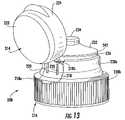
- FIG. 12is a perspective of a third and most preferred embodiment of the invention showing the cap in its as-molded condition
- FIG. 13is another perspective view thereof showing the cap in an intermediate position with the hinge arm locked onto the body of the cap;
- FIG. 14is a top plan view thereof
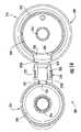
- FIG. 15is a bottom plan view thereof
- FIG. 16is a left side plan view thereof
- FIG. 17is a cross-sectional view thereof
- FIG. 18is another cross-sectional view thereof.
- FIG. 19is an enlarged cross-section view showing the sealing cap in the closure position and the two lines of peripheral sealing between the sealing cap flange and the annular sealing surface;
- FIG. 20is a perspective view of a fourth embodiment.
- FIG. 21is another perspective view of the fourth embodiment.
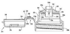
- FIG. 1depicts a first embodiment of a dispensing closure constructed in accordance with the principles of the invention.
- the dispensing closureis generally identified at 10 , and is shown secured to the upper end of the neck of container 12 .
- Container 12may assume the form of a plastic bottle, which may be tilted, and squeezed, to discharge its contents through closure 10 .
- FIG. 2shows dispensing closure 10 in its as-molded condition, prior to its securement to container 12 .
- Closure 10comprises sealing cap 14 , a closure body 16 , and a pair of hinges 18 , 20 that join the sealing cap to the closure body.
- Sealing cap 14is pivoted along the center line 22 of the hinges relative to closure body 16 .
- Sealing cap 14as shown in FIGS. 2 and 3 , includes an annular flange 24 , a camming lug 26 located on flange 24 in proximity to closure body 16 , and a depending peg 28 .
- Camming lug 26is curved, when viewed from above, and follows the contour of flange 24 .
- Flange 24remote from camming lug 26 , is reduced in thickness to form gripping surface 30 .
- Closure body 16includes a smooth upper wall 32 interrupted by dispensing orifice 34 ; the dispensing orifice communicates with the interior of the closure body.
- An annular sealing surface 36is located below upper wall 32 , and encircles closure body 16 , and skirt 38 below the upper wall 32 .
- Horizontal ledge 40is formed between annular sealing surface 36 and skirt 38 .
- An indentation 42is formed in the exterior surface of skirt 38 at a location remote from hinges 18 , 20 , and in alignment with camming lug 26 .
- Locator ring 44depends below upper wall 32 into the interior of closure body 16 , and internal threads 46 are arranged in helical fashion around the interior of skirt 38 . Ring 44 engages the end of the neck of container 12 to which dispensing closure 10 is applied, while threads 46 cooperate with complementary threads, or lugs, on the neck of the container 12 to secure dispensing closure 10 in fixed position.
- FIGS. 2 and 3show a dispensing closure, which is a unitary molding, in its as-molded condition, as it exits the mold.
- sealing cap 14is pivoted 180 degrees to its closed position.
- the sealing cap 14 as in FIGS. 6 and 7indicates the position into which sealing cap 14 is pivoted to achieve the desired molecular orientation.
- Hinges 18 , 20are thin, resilient plastic members that are deformed repeatedly over the useful life of the dispensing closure, so that sturdy, durable hinges are necessary for successful operation.
- Camming lug 26 as shown in FIG. 5extends beyond flange 24 . Consequently, when sealing cap 14 is pivoted to the upright position (shown in FIG. 4 ), camming lug 26 engages, and slides along annular sealing surface 36 on closure body 16 . The interference between camming lug 26 and annular sealing surface 36 stresses hinges 18 , 20 , and aligns the molecular structure of the plastic within the hinges. Edge 48 of camming lug 26 is rounded so that the camming lug does not gouge annular sealing surface 36 , an important consideration since sealing cap 14 is pivoted to its closed position shortly after removal from the mold. Rounded edge 48 also enhances the snap-action of sealing cap 14 .
- Camming lug 26is strategically located between spaced hinges 18 , 20 , for effectively stressing same within their elastic limits.
- the hingesmay be strengthened, if warranted, by the addition of reinforcing ribs 50 , 52 .
- the ribsare visible in FIG. 3 , and conform to the contour of the exterior edges of the hinges.
- the gap between sealing cap 14 and closure body 16 , that is spanned by hinges 18 , 20is also visible.
- Hinges 18 and 20are each integrally formed with a holder.
- Holder 54 for hinge 18is shown in FIG. 5 , and a similar holder (not shown) is formed with hinge 20 .
- an arcuate recess 56is removed from skirt 38 in the vicinity of the hinges and camming lug 26 .
- the size and shape of segment 56is shown in FIG. 2 .
- Recess 56imparts resiliency to holder 54 for hinge 18 , and does the same for the holder for hinge 20 .
- the limited resiliency of the holders for hinges 18 , 20permits some relaxation of the close tolerances associated with dispensing closures, without sacrificing desirable operational characteristics.
- recess 56receives camming lug 26 when sealing cap 14 is swung into sealing engagement with closure body 16 .
- Flange 24 of sealing cap 14contacts ledge 40 to form a snug seal about the circumference of ledge 40 .
- the inner surface of flange 24contacts annular sealing surface 36 to further enhance the efficiency of the sealing action, which keeps water and/or other fluids from reaching the interior of the closed dispenser closure.
- dispensing closure 10when closed, assumes a compact, or low, profile.
- FIG. 7shows gripping surface 30 on sealing cap 14 in relationship to indentation 42 on skirt 38 of closure body 16 .
- Surface 30 and indentation 42cooperate to allow the user of the cap to insert his finger beneath sealing cap 14 and manually lift same.
- camming lug 26After the sealing cap is pivoted partially toward its vertical, or opened position, camming lug 26 , in concert with hinges 18 , 20 imparts a snap-action to the sealing cap. Sealing cap 14 is retained in its vertical position by camming lug 26 pressing against annular sealing surface 36 on the closure body, in opposition to the forces imparted by hinges 18 and 20 , as shown in FIG. 4 .
- Closure 10realizes several advantages over known dispensing closures.
- the significant sealing area defined between flange 24 and ledge 40 , as well as the back-up seal between the surface of annular sealing surface 36 and flange 24allows the closure to be used on food products, such as ketchup, syrups, and the like.
- containers, for such products, such as flexible plastic bottlesare subjected to warm water baths to wash away excess product, dust, and the like.
- Such warm water bathshave occasionally left droplets of water behind—an unsightly proposition that offends the ultimate user and may even pose a minor health hazard.
- Closure 10as presently configured, obviates such problem in an efficient, lowcost fashion.
- pair of spaced hinges 18 , 20has materially increased the resistance of closure 10 to twisting forces. Such forces come into play as automated capping machinery applies torque to the closure to screw same onto the neck of a container or if consumers twist the closure to remove it from the neck of the container.
- Hinges 18 and 20are folded when sealing cap 14 is engaged, in sealing relationship, with closure body 16 . As shown in FIG. 6 , the folded hinges project outwardly a small distance from the closure body, and do not interfere with the sealing engagement of flange 24 and ledge 40 , and/or with the interior surface of flange 24 and annular sealing surface 36 . Also, closure 10 is aesthetically pleasing, with a slightly curved upper wall 32 on closure body 16 , such wall being unbroken except for dispensing orifice 34 . The manner in which camming lug 26 fits into recess 56 when sealing cap 14 is closed, is also pleasing to the eye, and precludes accumulation of excess food product, and/or dire, after discharge from container 12 .
- an alternative closure generally indicated at 100comprises a sealing cap 114 and a closure body 116 connected by hinge 118 .
- the closure 100generally has a taller configuration and the dispensing orifice 134 is centered on the closure body 116 .
- the dispensing orifice 134is composed a narrower upper channel 134 a and a wider lower channel 134 b to employ fluid dynamic principles to minimize spillage of the contents after the consumer dispenses the desired amount of product.
- Sealing cap 114is pivoted about the hinge between an open and closed configuration.
- Closure body 116is provided with deck 132 and dispensing orifice 134 centrally located and extending upwardly from deck 132 . Extending about the full circumference of the deck is sealing surface 136 . Located inwardly of this sealing surface is rib 152 and recess 154 .
- the structure of the sealing capcan also be seen in the cross-sectional view of FIG. 9 .
- the sealing cap 114is provided with a plug 128 that cooperates with dispensing orifice 134 .
- Extending from the sealing capis a peripheral skirt that cooperates with the sealing surface 136 .
- Extension 156extends from the underside of the sealing cap 114 and whose function will be described later.
- the closurehas threads 146 for attaching the closure to the neck of a bottle.
- FIG. 10shows an enclosed configuration of the closure. Clearly seen is the plug 128 in engagement with the dispensing orifice 134 . Also, the seal between the skirt of the sealing cap and the annular sealing surface 136 is completely seen, including the seal immediately adjacent the hinge. The seal between the skirt and annular sealing surface 136 extends about the entire periphery of the deck. As can be seen in this figure as well, is the placement of the extension 156 into the recess 154 . As can be seen, while closing the sealing cap, rib 152 and extension 156 come into direct contact, providing a camming action when the sealing cap is opened and closed.
- FIG. 11shows the bottom side of the closure. As can be seen, the bottom of recess 154 does not interfere with the dispensing of contents through dispensing orifice 134 or the engagement of threads 146 onto a container.
- FIGS. 12-19illustrates a third and most preferred embodiment of the invention that combines all of the valued features of the earlier described embodiments, such as low profile hinge structure, symmetrical outer body structure, centrally positioned dispensing orifice, and complete peripheral seals. Similar to the embodiment in FIGS. 8-11 , the dispensing orifice 234 is centrally aligned along the central axis of the closure body 216 . However, the hinge structure 218 is modified so as to blend into the peripheral skirt 238 of the closure body 216 , obviating the need to orient the closure 200 when mounted on a container 12 .
- the closureis generally indicated at 200 and comprises a sealing cap 214 and a closure body 216 integrally connected by a hinge structure 218 having two living hinges 218 a and 218 b.
- the closure sealing cap 214includes an upper wall 223 , annular flange wall 224 depending downwardly from the upper wall 223 , and a central sealing bead 226 depending downwardly from the center of the upper wall 223 .
- a camming lug 225Adjacent to the hinge 218 b and depending from the annular flange wall 224 of the sealing cap 214 , is a camming lug 225 having a rounded edge 227 .
- Camming lug 225extends beyond the annular flange wall 224 and functions similarly to the camming lug 26 shown in Fig.4 and described earlier of the first embodiment. Accordingly, when sealing cap 14 is pivoted to the upright position, camming lug 225 engages and slides along annular sealing surface 236 on the closure body 216 .
- the edge 227 of the camming lug 225is rounded so that the camming lug 225 does not gouge annular sealing surface 236 .
- the rounded edge 227also enhances the snap-action of sealing cap 214 .
- the closure body 216has an upper wall 232 including a centrally positioned dispensing orifice 234 , an annular sealing surface 236 , an upper peripheral skirt 238 a and a lower peripheral skirt 238 b.
- the sealing cap 214is connected to the closure body 216 by a hinge structure 218 that is specifically designed to form a low profile when snapped into position.
- the living hinge 218includes a hinge body 219 having a body hinge 218 a adjacent to the closure body 216 and a sealing cap hinge 218 b adjacent to the sealing cap 214 .
- the hinge body 219 and the upper peripheral skirt 238 a of the closure body 216are provided with interfitting mating formations 220 and 222 that snap together when the hinge body 219 is rotated about the body hinge 218 a . More specifically, the formations 220 and 222 comprise two hook-shaped tabs 220 in the surface of the upper peripheral flange 238 a and two complimentary receiving tabs 222 on the hinge body 219 .
- hinge structure 218is to provide a low profile, substantially flush engagement when snapped into position.
- the closure body 216 , hinge structure 218 , and sealing cap 214are laid out flat (See FIGS. 12 , 14 , 15 , and 18 ).
- the hinge body 219is pivoted about the body hinge 218 a so that the sealing cap hinge 218 b is positioned in proximity to the upper wall 232 of the closure body 216 , with the sealing cap oriented 90 degrees relative to the upper wall of the closure body (see FIG. 13 ).
- the sealing cap hinge 218 bhas a similar configuration to the hinge tab structure 26 shown in FIG. 4 , and is movable between an open position ( FIG. 13 ) and a closed position (not fully shown). When the sealing cap 214 is moved into the fully closed position the sealing bead 226 encircles and engages the outer walls of the dispensing orifice 234 to seal the dispensing orifice 234 at the opening.
- hinges 218 a , 218 bare formed in a 90 degree open configuration and contrary to industry practice of forming living hinges in a 180 degree open or flat configuration.
- the lower edge of the flange wall 224 of the sealing cap 214includes a continuous peripheral sealing bead 240 .
- the sealing bead 240engages the entire circumference of the annular sealing surface 236 to form a continuous primary seal around the circumference of the closure 200 .
- the outer peripheral edge of the upper wall 232includes a peripheral sealing bead 242 that engages the inner wall of the sealing cap flange 224 when the sealing cap 214 is moved to the closed position.
- FIG. 19shows the sealing configuration in better detail.
- the flow modulator 250has two spaced-apart flow walls 252 , 254 that are configured to face each other and form a channel 256 .
- the flow walls 252 , 254have two restriction edges 252 a , 254 b that taper inwardly towards one another to form two relief openings 258 that are generally V-shaped.
- the function of the flow modulator 250is to provide added restriction to the flow of a viscous fluid through the dispensing orifice and to prevent spillage of the fluid onto the outside surface of the upper wall 232 .
- FIGS. 20 and 21show an alternative embodiment for the configuration of the instant invention at 300 .
- the interfitting mating formationscomprise a T-shaped tab 320 located on the upper peripheral flange 338 a , and a complimentary slot 322 located on the hinge body 319 .
Landscapes
- Engineering & Computer Science (AREA)
- Mechanical Engineering (AREA)
- Closures For Containers (AREA)
Abstract
Description
Claims (15)
Priority Applications (5)
| Application Number | Priority Date | Filing Date | Title |
|---|---|---|---|
| US10/960,179US7322493B2 (en) | 2003-10-09 | 2004-10-07 | Dispensing closure having complete peripheral seal |
| US11/163,032US8523025B2 (en) | 2003-10-09 | 2005-10-03 | Dispensing closure having flow modulator and syneresis capture |
| US11/679,374US7314150B2 (en) | 2003-10-09 | 2007-02-27 | Dispensing closure with cap structure having dual living hinges |
| US11/876,067US7617954B2 (en) | 2004-10-07 | 2007-10-22 | Dispensing closure with latch back |
| US12/576,509US7762438B2 (en) | 2003-10-09 | 2009-10-09 | Dispensing closure with latch back |
Applications Claiming Priority (3)
| Application Number | Priority Date | Filing Date | Title |
|---|---|---|---|
| US50952303P | 2003-10-09 | 2003-10-09 | |
| US58751804P | 2004-07-13 | 2004-07-13 | |
| US10/960,179US7322493B2 (en) | 2003-10-09 | 2004-10-07 | Dispensing closure having complete peripheral seal |
Related Child Applications (3)
| Application Number | Title | Priority Date | Filing Date |
|---|---|---|---|
| US11/163,032Continuation-In-PartUS8523025B2 (en) | 2003-10-09 | 2005-10-03 | Dispensing closure having flow modulator and syneresis capture |
| US11/679,374ContinuationUS7314150B2 (en) | 2003-10-09 | 2007-02-27 | Dispensing closure with cap structure having dual living hinges |
| US11/876,067Continuation-In-PartUS7617954B2 (en) | 2003-10-09 | 2007-10-22 | Dispensing closure with latch back |
Publications (2)
| Publication Number | Publication Date |
|---|---|
| US20050087550A1 US20050087550A1 (en) | 2005-04-28 |
| US7322493B2true US7322493B2 (en) | 2008-01-29 |
Family
ID=33457713
Family Applications (2)
| Application Number | Title | Priority Date | Filing Date |
|---|---|---|---|
| US10/960,179Expired - LifetimeUS7322493B2 (en) | 2003-10-09 | 2004-10-07 | Dispensing closure having complete peripheral seal |
| US11/679,374Expired - LifetimeUS7314150B2 (en) | 2003-10-09 | 2007-02-27 | Dispensing closure with cap structure having dual living hinges |
Family Applications After (1)
| Application Number | Title | Priority Date | Filing Date |
|---|---|---|---|
| US11/679,374Expired - LifetimeUS7314150B2 (en) | 2003-10-09 | 2007-02-27 | Dispensing closure with cap structure having dual living hinges |
Country Status (4)
| Country | Link |
|---|---|
| US (2) | US7322493B2 (en) |
| CA (1) | CA2484412C (en) |
| DE (2) | DE102004049633B4 (en) |
| GB (1) | GB2407086B (en) |
Cited By (10)
| Publication number | Priority date | Publication date | Assignee | Title |
|---|---|---|---|---|
| US20090166361A1 (en)* | 2007-12-29 | 2009-07-02 | Airsec | Two-part, flip top, snap cap for vials |
| US20100065589A1 (en)* | 2003-10-09 | 2010-03-18 | Polytop Corporation | Dispensing closure with latch back |
| US20100072231A1 (en)* | 2008-09-25 | 2010-03-25 | Bloom Kenneth S | Baffled Dispensing Closure |
| US20100140304A1 (en)* | 2008-12-09 | 2010-06-10 | Steve Walunis | One-piece dispensing closure |
| US20100224643A1 (en)* | 2009-03-03 | 2010-09-09 | Weatherchem Corporation | Dispensing closure |
| US20100230446A1 (en)* | 2009-03-12 | 2010-09-16 | Weatherchem Corporation | Sift-resistant dispensing closure |
| US20110000137A1 (en)* | 2008-02-14 | 2011-01-06 | Druitt Rodney M | Closure with an external hinge |
| US11059633B2 (en) | 2019-10-31 | 2021-07-13 | Cheer Pack North America | Flip-top closure for container |
| USD980069S1 (en) | 2020-07-14 | 2023-03-07 | Ball Corporation | Metallic dispensing lid |
| US12168551B2 (en) | 2021-03-01 | 2024-12-17 | Ball Corporation | Metal container and end closure with seal |
Families Citing this family (31)
| Publication number | Priority date | Publication date | Assignee | Title |
|---|---|---|---|---|
| US7617954B2 (en)* | 2004-10-07 | 2009-11-17 | Polytop Corporation, A Rhode Island Corporation | Dispensing closure with latch back |
| US7322493B2 (en)* | 2003-10-09 | 2008-01-29 | Polytop Corporation | Dispensing closure having complete peripheral seal |
| US8523025B2 (en)* | 2003-10-09 | 2013-09-03 | Mwv Slatersville, Llc | Dispensing closure having flow modulator and syneresis capture |
| US7549559B2 (en)* | 2005-07-22 | 2009-06-23 | Conroy Foods, Inc. | Directional pour spout container cap |
| FR2889169A1 (en)* | 2005-08-01 | 2007-02-02 | Tetra Laval Holdings & Finance | CLOSURE DEVICE AND CONTAINER EQUIPPED WITH SUCH A DEVICE |
| US7668884B2 (en)* | 2005-11-28 | 2010-02-23 | Commvault Systems, Inc. | Systems and methods for classifying and transferring information in a storage network |
| US8336745B2 (en)* | 2006-09-01 | 2012-12-25 | Mwv Slatersville, Llc | Dispensing closure having a flow conduit with key-hole shape |
| DE202009000138U1 (en)* | 2009-01-05 | 2009-03-19 | Weener Plastik Ag | clasp closure |
| FR2949761B1 (en)* | 2009-09-10 | 2011-12-02 | Oreal | DEVICE FOR CONDITIONING AND DISPENSING A PRODUCT |
| US8833586B2 (en)* | 2010-04-16 | 2014-09-16 | Runway Blue, Llc | Bottle closure with integrated flip top handle |
| AU2011292173B2 (en)* | 2010-08-16 | 2016-02-11 | Kraft Foods Group Brands Llc | Perforated shrink wrap sleeves and containers |
| US9663271B2 (en) | 2012-07-16 | 2017-05-30 | ProAmpac Intermediate, Inc. | Bistable pull-snap hold open mechanism and method |
| CN105008236B (en)* | 2013-02-08 | 2016-11-16 | 奥布里斯特封闭瑞士有限公司 | Capping or improvements related to capping |
| EP2969804B1 (en)* | 2013-03-15 | 2019-01-16 | Silgan Dispensing Systems Slatersville LLC | Vented closure assembly for a spray container |
| USD775950S1 (en) | 2014-02-10 | 2017-01-10 | Obrist Closures Switzerland Gmbh | Closing means for packaging |
| CA3064444A1 (en)* | 2017-05-25 | 2018-11-29 | Vishaal Boehm Verma | Bistable pull-snap hold open mechanism and method |
| US11040806B2 (en)* | 2017-12-15 | 2021-06-22 | Husky Injection Molding Systems Ltd. | Closure cap for a container |
| ES2934509T3 (en) | 2018-12-21 | 2023-02-22 | Heinz Co Brands H J Llc | Container, closure and methods of manufacture |
| US11292642B2 (en) | 2018-12-21 | 2022-04-05 | H. J. Heinz Company Brands Llc | Container, closure, and methods for manufacture |
| USD889260S1 (en) | 2018-12-21 | 2020-07-07 | H.J. Heinz Company Brands Llc | Closure for a container |
| ES2802451B2 (en)* | 2019-07-11 | 2021-05-25 | Sanchez Jose Francisco Gonzalez | Closing cap with extendable hinge for containers |
| EP4025513A4 (en) | 2019-09-06 | 2023-10-04 | Silgan White Cap LLC | HINGED CLOSURE MEANS WITH A CLIP |
| US11891218B2 (en) | 2019-09-20 | 2024-02-06 | H.J. Heinz Company Brands Llc | Container, closure, and methods for manufacture |
| USD926577S1 (en)* | 2019-09-23 | 2021-08-03 | Verdant Ventures | Tamper-resistant lid assembly |
| MX2022005979A (en)* | 2019-11-18 | 2022-09-02 | Johnson & Johnson Consumer Inc | FLIP CLOSURE. |
| CA3163971A1 (en)* | 2020-02-07 | 2021-08-12 | Stephane Graux | Hinged stopper |
| IT202000003724A1 (en)* | 2020-02-24 | 2021-08-24 | Affaba & Ferrari S R L | FLIP TOP CAP FOR CONTAINERS WITH EVIDENCE OF FIRST OPENING |
| US12280921B2 (en)* | 2020-08-20 | 2025-04-22 | Sidel Participations Sas | Hinged closure |
| BR112023017918A2 (en)* | 2021-03-10 | 2023-10-31 | Bericap Holding Gmbh | CONTAINER CLOSING SYSTEM |
| EP4429966A1 (en) | 2021-11-08 | 2024-09-18 | Silgan White Cap LLC | Protrusion on container neck |
| MX2024008457A (en) | 2022-02-11 | 2024-07-30 | Silgan White Cap LLC | Tethered, hinged closure with modified primary slit. |
Citations (16)
| Publication number | Priority date | Publication date | Assignee | Title |
|---|---|---|---|---|
| GB207638A (en) | 1922-09-08 | 1923-12-06 | Thomas Browett | Improvements in resilient wheels |
| DE7631199U1 (en) | 1976-10-06 | 1977-01-20 | Wischerath Kg Josef | Plastic lid closure for containers, especially for cans, bottles and the like |
| US4010875A (en)* | 1975-01-16 | 1977-03-08 | Le Bouchage Mecanique | Pourer-stopper |
| US4158902A (en)* | 1977-09-30 | 1979-06-26 | Chernack Milton P | Integral snap action hinge |
| US4573600A (en)* | 1983-06-10 | 1986-03-04 | Alfatechnic Ag | Snap closure for a container |
| US4635823A (en) | 1985-05-09 | 1987-01-13 | Gene Stull | Dispensing closure construction |
| US4917253A (en) | 1989-03-30 | 1990-04-17 | Continental Plastics, Inc. | Container-closure with fold over projections |
| US5088612A (en)* | 1991-06-10 | 1992-02-18 | Comar, Inc. | Vial cap |
| US5271536A (en)* | 1992-02-07 | 1993-12-21 | Polytop Corporation | Flexible holder for "living" hinge joining lid to closure body of dispensing closure |
| US5437383A (en) | 1993-06-11 | 1995-08-01 | Stull; Gene | Snap-hinge closure cap with full circumferential seal |
| US5938087A (en) | 1997-06-17 | 1999-08-17 | Aptargroup, Inc. | Spurt minimizing dispensing structure |
| US6116477A (en) | 1999-12-13 | 2000-09-12 | Courtesy Corporation | Two piece hinge closure |
| US6305563B1 (en) | 1999-01-12 | 2001-10-23 | Aptargroup, Inc, | One-piece dispensing structure and method and apparatus for making same |
| US20020096532A1 (en) | 2001-01-24 | 2002-07-25 | Courtesy Corporation. | Two piece hinged closure |
| EP1386849A1 (en) | 2002-08-02 | 2004-02-04 | Crown Cork & Seal Technologies Corporation | Water-tight closure |
| US6766926B1 (en)* | 2002-07-29 | 2004-07-27 | Owens-Illinois Closure Inc. | Dispensing closure, package and method of manufacture |
Family Cites Families (5)
| Publication number | Priority date | Publication date | Assignee | Title |
|---|---|---|---|---|
| GB2076378B (en)* | 1980-05-09 | 1984-02-15 | Windmill Plastics Ltd | Closure for container |
| US4778071A (en)* | 1988-02-16 | 1988-10-18 | Owens-Illinois Closure Inc. | Closure with snap type hinge |
| IT1307286B1 (en) | 1999-12-03 | 2001-10-30 | Ennio Cardia | DEVICE FOR THE CONTROLLED DISPENSING OF LIQUIDS AND / OR SUBSTANCES AND / OR SLIDING SUBSTANCES. |
| FR2855815B1 (en)* | 2003-06-06 | 2006-03-17 | Zebra Company | UNLOCKABLE COVER CAP WITH ELASTIC RECALL |
| US7322493B2 (en) | 2003-10-09 | 2008-01-29 | Polytop Corporation | Dispensing closure having complete peripheral seal |
- 2004
- 2004-10-07USUS10/960,179patent/US7322493B2/ennot_activeExpired - Lifetime
- 2004-10-08CACA002484412Apatent/CA2484412C/ennot_activeExpired - Lifetime
- 2004-10-08GBGB0422361Apatent/GB2407086B/ennot_activeExpired - Lifetime
- 2004-10-11DEDE102004049633Apatent/DE102004049633B4/ennot_activeExpired - Lifetime
- 2004-10-11DEDE102004064223.0Apatent/DE102004064223B3/ennot_activeExpired - Lifetime
- 2007
- 2007-02-27USUS11/679,374patent/US7314150B2/ennot_activeExpired - Lifetime
Patent Citations (17)
| Publication number | Priority date | Publication date | Assignee | Title |
|---|---|---|---|---|
| GB207638A (en) | 1922-09-08 | 1923-12-06 | Thomas Browett | Improvements in resilient wheels |
| US4010875A (en)* | 1975-01-16 | 1977-03-08 | Le Bouchage Mecanique | Pourer-stopper |
| DE7631199U1 (en) | 1976-10-06 | 1977-01-20 | Wischerath Kg Josef | Plastic lid closure for containers, especially for cans, bottles and the like |
| US4158902A (en)* | 1977-09-30 | 1979-06-26 | Chernack Milton P | Integral snap action hinge |
| US4573600A (en)* | 1983-06-10 | 1986-03-04 | Alfatechnic Ag | Snap closure for a container |
| US4635823A (en) | 1985-05-09 | 1987-01-13 | Gene Stull | Dispensing closure construction |
| US4917253A (en) | 1989-03-30 | 1990-04-17 | Continental Plastics, Inc. | Container-closure with fold over projections |
| US5088612A (en)* | 1991-06-10 | 1992-02-18 | Comar, Inc. | Vial cap |
| US5271536A (en)* | 1992-02-07 | 1993-12-21 | Polytop Corporation | Flexible holder for "living" hinge joining lid to closure body of dispensing closure |
| US5437383A (en) | 1993-06-11 | 1995-08-01 | Stull; Gene | Snap-hinge closure cap with full circumferential seal |
| US5938087A (en) | 1997-06-17 | 1999-08-17 | Aptargroup, Inc. | Spurt minimizing dispensing structure |
| US6305563B1 (en) | 1999-01-12 | 2001-10-23 | Aptargroup, Inc, | One-piece dispensing structure and method and apparatus for making same |
| US6116477A (en) | 1999-12-13 | 2000-09-12 | Courtesy Corporation | Two piece hinge closure |
| US20020096532A1 (en) | 2001-01-24 | 2002-07-25 | Courtesy Corporation. | Two piece hinged closure |
| US6478184B2 (en)* | 2001-01-24 | 2002-11-12 | Courtesy Corporation | Two piece hinged closure |
| US6766926B1 (en)* | 2002-07-29 | 2004-07-27 | Owens-Illinois Closure Inc. | Dispensing closure, package and method of manufacture |
| EP1386849A1 (en) | 2002-08-02 | 2004-02-04 | Crown Cork & Seal Technologies Corporation | Water-tight closure |
Cited By (16)
| Publication number | Priority date | Publication date | Assignee | Title |
|---|---|---|---|---|
| US20100065589A1 (en)* | 2003-10-09 | 2010-03-18 | Polytop Corporation | Dispensing closure with latch back |
| US7762438B2 (en) | 2003-10-09 | 2010-07-27 | Polytop Corporation | Dispensing closure with latch back |
| US20090166361A1 (en)* | 2007-12-29 | 2009-07-02 | Airsec | Two-part, flip top, snap cap for vials |
| US9415909B2 (en)* | 2008-02-14 | 2016-08-16 | Creanova Universal Closures Ltd. | Closure with an external hinge positioned outside a sidewall of the closure |
| US20110000137A1 (en)* | 2008-02-14 | 2011-01-06 | Druitt Rodney M | Closure with an external hinge |
| US20100072231A1 (en)* | 2008-09-25 | 2010-03-25 | Bloom Kenneth S | Baffled Dispensing Closure |
| US9371162B2 (en) | 2008-12-09 | 2016-06-21 | Weatherchem Corporation | One-piece dispensing closure |
| US20100140304A1 (en)* | 2008-12-09 | 2010-06-10 | Steve Walunis | One-piece dispensing closure |
| US20100224643A1 (en)* | 2009-03-03 | 2010-09-09 | Weatherchem Corporation | Dispensing closure |
| US8550313B2 (en) | 2009-03-12 | 2013-10-08 | Weatherchem Corporation | Sift-resistant dispensing closure |
| US20100230446A1 (en)* | 2009-03-12 | 2010-09-16 | Weatherchem Corporation | Sift-resistant dispensing closure |
| US10589909B2 (en) | 2009-03-12 | 2020-03-17 | Weatherchem Corporation | Sift-resistant dispensing closure |
| US11548699B2 (en) | 2009-03-12 | 2023-01-10 | Weatherchem Corporation | Sift-resistant dispensing closure |
| US11059633B2 (en) | 2019-10-31 | 2021-07-13 | Cheer Pack North America | Flip-top closure for container |
| USD980069S1 (en) | 2020-07-14 | 2023-03-07 | Ball Corporation | Metallic dispensing lid |
| US12168551B2 (en) | 2021-03-01 | 2024-12-17 | Ball Corporation | Metal container and end closure with seal |
Also Published As
| Publication number | Publication date |
|---|---|
| CA2484412C (en) | 2008-12-02 |
| US20070138124A1 (en) | 2007-06-21 |
| US20050087550A1 (en) | 2005-04-28 |
| GB2407086A (en) | 2005-04-20 |
| DE102004064223B3 (en) | 2015-05-21 |
| GB2407086B (en) | 2006-03-22 |
| DE102004049633B4 (en) | 2012-03-29 |
| GB0422361D0 (en) | 2004-11-10 |
| CA2484412A1 (en) | 2005-04-09 |
| DE102004049633A1 (en) | 2005-06-23 |
| US7314150B2 (en) | 2008-01-01 |
Similar Documents
| Publication | Publication Date | Title |
|---|---|---|
| US7322493B2 (en) | Dispensing closure having complete peripheral seal | |
| US8523025B2 (en) | Dispensing closure having flow modulator and syneresis capture | |
| US7617954B2 (en) | Dispensing closure with latch back | |
| US7762438B2 (en) | Dispensing closure with latch back | |
| US5499736A (en) | Reclosable, removable cap for reusable shaker dispenser bottle | |
| US7299952B2 (en) | Container closure and method of assembly | |
| US6622895B2 (en) | Dispenser package for fluent products and method of manufacture | |
| AU2002338746B2 (en) | Dispensing closure for a container that holds pourable material | |
| US6672487B1 (en) | Fluid dispensing closure, package and method of manufacture | |
| US4632266A (en) | Container cap | |
| US4505400A (en) | Slide type cap closure | |
| US6932249B1 (en) | Toggle-action dispensing closure, package and method of making | |
| NL2032534B1 (en) | A spouted container and closure assembly. |
Legal Events
| Date | Code | Title | Description |
|---|---|---|---|
| AS | Assignment | Owner name:POLYTOP CORPORATION, RHODE ISLAND Free format text:ASSIGNMENT OF ASSIGNORS INTEREST;ASSIGNOR:SKILLIN, CLIFFORD W.;REEL/FRAME:015996/0397 Effective date:20050401 | |
| STCF | Information on status: patent grant | Free format text:PATENTED CASE | |
| FPAY | Fee payment | Year of fee payment:4 | |
| FEPP | Fee payment procedure | Free format text:PAT HOLDER NO LONGER CLAIMS SMALL ENTITY STATUS, ENTITY STATUS SET TO UNDISCOUNTED (ORIGINAL EVENT CODE: STOL); ENTITY STATUS OF PATENT OWNER: LARGE ENTITY | |
| AS | Assignment | Owner name:POLYTOP LLC, A RHODE ISLAND LIMITED LIABILITY COMP Free format text:CONVERSION OF CORPORATION TO LLC;ASSIGNOR:POLYTOP CORPORATION, A RHODE ISLAND CORPORATION;REEL/FRAME:027941/0748 Effective date:20111228 | |
| AS | Assignment | Owner name:MWV SLATERSVILLE, LLC, A LIMITED LIABILITY COMPANY Free format text:CHANGE OF NAME;ASSIGNOR:POLYTOP LLC, A RHODE ISLAND LIMITED LIABILITY COMPANY;REEL/FRAME:029291/0571 Effective date:20120620 | |
| FPAY | Fee payment | Year of fee payment:8 | |
| AS | Assignment | Owner name:WESTROCK SLATERSVILLE, LLC, GEORGIA Free format text:CHANGE OF NAME;ASSIGNOR:MWV SLATERSVILLE, LLC;REEL/FRAME:040840/0399 Effective date:20150818 | |
| MAFP | Maintenance fee payment | Free format text:PAYMENT OF MAINTENANCE FEE, 12TH YEAR, LARGE ENTITY (ORIGINAL EVENT CODE: M1553); ENTITY STATUS OF PATENT OWNER: LARGE ENTITY Year of fee payment:12 |