US7322245B2 - Apparatus and method for measuring a fluid flowing in a pipe using acoustic pressures - Google Patents
Apparatus and method for measuring a fluid flowing in a pipe using acoustic pressuresDownload PDFInfo
- Publication number
- US7322245B2 US7322245B2US11/295,250US29525005AUS7322245B2US 7322245 B2US7322245 B2US 7322245B2US 29525005 AUS29525005 AUS 29525005AUS 7322245 B2US7322245 B2US 7322245B2
- Authority
- US
- United States
- Prior art keywords
- pipe
- sound
- mix
- speed
- sensors
- Prior art date
- Legal status (The legal status is an assumption and is not a legal conclusion. Google has not performed a legal analysis and makes no representation as to the accuracy of the status listed.)
- Expired - Fee Related
Links
- 239000012530fluidSubstances0.000titleclaimsabstractdescription104
- 238000000034methodMethods0.000titleclaimsabstractdescription51
- 239000000203mixtureSubstances0.000claimsabstractdescription228
- 230000004044responseEffects0.000claimsdescription14
- 239000000470constituentSubstances0.000claimsdescription13
- 230000008569processEffects0.000claimsdescription10
- 230000005534acoustic noiseEffects0.000claimsdescription8
- 230000001902propagating effectEffects0.000claimsdescription7
- 239000012223aqueous fractionSubstances0.000abstractdescription22
- 238000004519manufacturing processMethods0.000abstractdescription15
- 238000012545processingMethods0.000abstractdescription15
- -1e.g.Substances0.000abstractdescription12
- 230000005693optoelectronicsEffects0.000abstract1
- XLYOFNOQVPJJNP-UHFFFAOYSA-NwaterSubstancesOXLYOFNOQVPJJNP-UHFFFAOYSA-N0.000description38
- 239000000835fiberSubstances0.000description37
- 230000003287optical effectEffects0.000description28
- 238000005259measurementMethods0.000description24
- 238000012360testing methodMethods0.000description17
- 238000009530blood pressure measurementMethods0.000description16
- 230000006870functionEffects0.000description16
- 239000007789gasSubstances0.000description15
- 239000000463materialSubstances0.000description14
- 239000013307optical fiberSubstances0.000description12
- 230000005855radiationEffects0.000description12
- 230000035945sensitivityEffects0.000description10
- 238000013459approachMethods0.000description9
- 230000008859changeEffects0.000description8
- 238000006073displacement reactionMethods0.000description8
- 238000010586diagramMethods0.000description7
- 230000006854communicationEffects0.000description6
- 238000004891communicationMethods0.000description6
- 238000003491arrayMethods0.000description5
- 230000000694effectsEffects0.000description5
- 241000237858GastropodaSpecies0.000description4
- 229910000831SteelInorganic materials0.000description4
- 230000005540biological transmissionEffects0.000description4
- 238000002955isolationMethods0.000description4
- 239000007788liquidSubstances0.000description4
- 239000004576sandSubstances0.000description4
- 239000010959steelSubstances0.000description4
- 230000001133accelerationEffects0.000description3
- 239000002253acidSubstances0.000description3
- 238000004458analytical methodMethods0.000description3
- 230000004323axial lengthEffects0.000description3
- 230000008901benefitEffects0.000description3
- 238000004364calculation methodMethods0.000description3
- 238000011156evaluationMethods0.000description3
- 230000005284excitationEffects0.000description3
- 230000014509gene expressionEffects0.000description3
- 229910052500inorganic mineralInorganic materials0.000description3
- 239000011707mineralSubstances0.000description3
- 238000012544monitoring processMethods0.000description3
- 230000005236sound signalEffects0.000description3
- 239000000126substanceSubstances0.000description3
- 230000002123temporal effectEffects0.000description3
- QAOWNCQODCNURD-UHFFFAOYSA-NSulfuric acidChemical compoundOS(O)(=O)=OQAOWNCQODCNURD-UHFFFAOYSA-N0.000description2
- 239000003518causticsSubstances0.000description2
- 230000008602contractionEffects0.000description2
- 230000007613environmental effectEffects0.000description2
- 238000004880explosionMethods0.000description2
- 238000001914filtrationMethods0.000description2
- 239000008240homogeneous mixtureSubstances0.000description2
- 239000011159matrix materialSubstances0.000description2
- 238000000691measurement methodMethods0.000description2
- 230000007246mechanismEffects0.000description2
- 238000005065miningMethods0.000description2
- 239000002245particleSubstances0.000description2
- 239000003208petroleumSubstances0.000description2
- 230000003068static effectEffects0.000description2
- 238000012935AveragingMethods0.000description1
- 208000032365Electromagnetic interferenceDiseases0.000description1
- 239000004593EpoxySubstances0.000description1
- 229920000271Kevlar®Polymers0.000description1
- RTAQQCXQSZGOHL-UHFFFAOYSA-NTitaniumChemical compound[Ti]RTAQQCXQSZGOHL-UHFFFAOYSA-N0.000description1
- 150000007513acidsChemical class0.000description1
- 238000007792additionMethods0.000description1
- 239000000853adhesiveSubstances0.000description1
- 230000001070adhesive effectEffects0.000description1
- 230000007175bidirectional communicationEffects0.000description1
- 230000015572biosynthetic processEffects0.000description1
- 239000000919ceramicSubstances0.000description1
- 238000012512characterization methodMethods0.000description1
- 238000006243chemical reactionMethods0.000description1
- 238000004939cokingMethods0.000description1
- 238000002485combustion reactionMethods0.000description1
- 239000002131composite materialSubstances0.000description1
- 230000006835compressionEffects0.000description1
- 238000007906compressionMethods0.000description1
- 230000007797corrosionEffects0.000description1
- 238000005260corrosionMethods0.000description1
- 238000013016dampingMethods0.000description1
- 230000001419dependent effectEffects0.000description1
- 230000005672electromagnetic fieldEffects0.000description1
- 239000002360explosiveSubstances0.000description1
- 239000011888foilSubstances0.000description1
- 238000005755formation reactionMethods0.000description1
- 239000011521glassSubstances0.000description1
- 239000003292glueSubstances0.000description1
- 238000010438heat treatmentMethods0.000description1
- 239000001257hydrogenSubstances0.000description1
- 229910052739hydrogenInorganic materials0.000description1
- 125000004435hydrogen atomChemical class[H]*0.000description1
- 230000006872improvementEffects0.000description1
- 238000012994industrial processingMethods0.000description1
- 238000007689inspectionMethods0.000description1
- 238000013507mappingMethods0.000description1
- 238000012986modificationMethods0.000description1
- 230000004048modificationEffects0.000description1
- 239000003129oil wellSubstances0.000description1
- 238000005457optimizationMethods0.000description1
- 230000001151other effectEffects0.000description1
- 238000004886process controlMethods0.000description1
- 230000009467reductionEffects0.000description1
- 238000007670refiningMethods0.000description1
- 230000029058respiratory gaseous exchangeEffects0.000description1
- 238000001223reverse osmosisMethods0.000description1
- 239000011435rockSubstances0.000description1
- 238000000926separation methodMethods0.000description1
- 230000008054signal transmissionEffects0.000description1
- 239000002002slurrySubstances0.000description1
- 239000007787solidSubstances0.000description1
- 230000003595spectral effectEffects0.000description1
- 238000013517stratificationMethods0.000description1
- 229910052719titaniumInorganic materials0.000description1
- 239000010936titaniumSubstances0.000description1
- 238000012546transferMethods0.000description1
- 230000001052transient effectEffects0.000description1
Images


Classifications
- G—PHYSICS
- G01—MEASURING; TESTING
- G01H—MEASUREMENT OF MECHANICAL VIBRATIONS OR ULTRASONIC, SONIC OR INFRASONIC WAVES
- G01H5/00—Measuring propagation velocity of ultrasonic, sonic or infrasonic waves, e.g. of pressure waves
- G—PHYSICS
- G01—MEASURING; TESTING
- G01N—INVESTIGATING OR ANALYSING MATERIALS BY DETERMINING THEIR CHEMICAL OR PHYSICAL PROPERTIES
- G01N29/00—Investigating or analysing materials by the use of ultrasonic, sonic or infrasonic waves; Visualisation of the interior of objects by transmitting ultrasonic or sonic waves through the object
- G01N29/02—Analysing fluids
- G01N29/024—Analysing fluids by measuring propagation velocity or propagation time of acoustic waves
- G—PHYSICS
- G01—MEASURING; TESTING
- G01N—INVESTIGATING OR ANALYSING MATERIALS BY DETERMINING THEIR CHEMICAL OR PHYSICAL PROPERTIES
- G01N29/00—Investigating or analysing materials by the use of ultrasonic, sonic or infrasonic waves; Visualisation of the interior of objects by transmitting ultrasonic or sonic waves through the object
- G01N29/36—Detecting the response signal, e.g. electronic circuits specially adapted therefor
- G01N29/42—Detecting the response signal, e.g. electronic circuits specially adapted therefor by frequency filtering or by tuning to resonant frequency
- G—PHYSICS
- G01—MEASURING; TESTING
- G01N—INVESTIGATING OR ANALYSING MATERIALS BY DETERMINING THEIR CHEMICAL OR PHYSICAL PROPERTIES
- G01N29/00—Investigating or analysing materials by the use of ultrasonic, sonic or infrasonic waves; Visualisation of the interior of objects by transmitting ultrasonic or sonic waves through the object
- G01N29/44—Processing the detected response signal, e.g. electronic circuits specially adapted therefor
- G01N29/46—Processing the detected response signal, e.g. electronic circuits specially adapted therefor by spectral analysis, e.g. Fourier analysis or wavelet analysis
- G—PHYSICS
- G01—MEASURING; TESTING
- G01N—INVESTIGATING OR ANALYSING MATERIALS BY DETERMINING THEIR CHEMICAL OR PHYSICAL PROPERTIES
- G01N2291/00—Indexing codes associated with group G01N29/00
- G01N2291/02—Indexing codes associated with the analysed material
- G01N2291/021—Gases
- G01N2291/0217—Smoke, combustion gases
- G—PHYSICS
- G01—MEASURING; TESTING
- G01N—INVESTIGATING OR ANALYSING MATERIALS BY DETERMINING THEIR CHEMICAL OR PHYSICAL PROPERTIES
- G01N2291/00—Indexing codes associated with group G01N29/00
- G01N2291/02—Indexing codes associated with the analysed material
- G01N2291/022—Liquids
- G01N2291/0222—Binary liquids
- G—PHYSICS
- G01—MEASURING; TESTING
- G01N—INVESTIGATING OR ANALYSING MATERIALS BY DETERMINING THEIR CHEMICAL OR PHYSICAL PROPERTIES
- G01N2291/00—Indexing codes associated with group G01N29/00
- G01N2291/02—Indexing codes associated with the analysed material
- G01N2291/022—Liquids
- G01N2291/0224—Mixtures of three or more liquids
- G—PHYSICS
- G01—MEASURING; TESTING
- G01N—INVESTIGATING OR ANALYSING MATERIALS BY DETERMINING THEIR CHEMICAL OR PHYSICAL PROPERTIES
- G01N2291/00—Indexing codes associated with group G01N29/00
- G01N2291/02—Indexing codes associated with the analysed material
- G01N2291/028—Material parameters
- G01N2291/02836—Flow rate, liquid level
- G—PHYSICS
- G01—MEASURING; TESTING
- G01N—INVESTIGATING OR ANALYSING MATERIALS BY DETERMINING THEIR CHEMICAL OR PHYSICAL PROPERTIES
- G01N2291/00—Indexing codes associated with group G01N29/00
- G01N2291/02—Indexing codes associated with the analysed material
- G01N2291/028—Material parameters
- G01N2291/02845—Humidity, wetness
- G—PHYSICS
- G01—MEASURING; TESTING
- G01N—INVESTIGATING OR ANALYSING MATERIALS BY DETERMINING THEIR CHEMICAL OR PHYSICAL PROPERTIES
- G01N2291/00—Indexing codes associated with group G01N29/00
- G01N2291/02—Indexing codes associated with the analysed material
- G01N2291/028—Material parameters
- G01N2291/02872—Pressure
- G—PHYSICS
- G01—MEASURING; TESTING
- G01N—INVESTIGATING OR ANALYSING MATERIALS BY DETERMINING THEIR CHEMICAL OR PHYSICAL PROPERTIES
- G01N2291/00—Indexing codes associated with group G01N29/00
- G01N2291/10—Number of transducers
- G01N2291/106—Number of transducers one or more transducer arrays
Definitions
- This inventionrelates to fluid parameter measurement in pipes and more particularly to measuring speed of sound and parameters related thereto of fluids in pipes using acoustic pressures for use in industrial sensing applications.
- An industrial process sensoris typically a transducer that responds to a measurand with a sensing element and converts the variable to a standardized transmission signal, e.g., an electrical or optical signal, that is a function of the measurand.
- Industrial process sensorsutilize transducers that include flow measurements of an industrial process such as that derived from slurries, liquids, vapors and gasses in refinery, chemical, paper, pulp, petroleum, gas, pharmaceutical, food, mining, minerals and other fluid processing plants.
- Industrial process sensorsare often placed in or near the process fluids, or in field applications. Often, these field applications are subject to harsh and varying environmental conditions that provide challenges for designers of such sensors.
- Flow measurementis one of the largest segments of the industrial sensing and instrumentation market. Industries in which flow measurement is prevalent includes petroleum, chemical, pulp, paper, food, and mining and minerals.
- Typical electronic, or other, transducers of the prior artoften cannot be placed in industrial process environments due to sensitivity to electro-magnetic interference, radiation, heat, corrosion, fire, explosion or other environmental factors. It is for these reasons that fiber optic based sensors are being incorporated into industrial process control environments in increasing number.
- Such techniqueshave a pair of acoustic transmitters/receivers (transceivers) that generate a sound signal and measure the time it takes for the sound signal to travel between the transceivers. This is also known as a “sing-around” or “transit time” method.
- transceiversacoustic transmitters/receivers
- Thisis also known as a “sing-around” or “transit time” method.
- such techniquesrequire precise control of the acoustic source and are costly and/or complex to implement in electronics.
- ultrasonic acoustic signalsas the sound signal measured, which are high frequency, short wavelength signals (i.e., wavelengths that are short compared to the diameter of the pipe).
- Typical ultrasonic devicesoperate near 200 kHz, which corresponds to a wavelength of about 0.3 inches in water.
- the fluidshould be homogeneous down to length scales of several times smaller than the acoustic signal wavelength.
- the criteria for homogeneity of the fluidbecomes increasingly stricter with shorter wavelength signals.
- Objects of the present inventioninclude provision of a system for measuring the speed of sound of fluids in pipes in industrial fluid processes.
- an apparatus for industrial sensing applications for measuring at least one parameter of a mixture of at least one fluid in a pipecomprising a spatial array of at least two pressure sensors, disposed at different axial locations along the pipe, and each measuring an acoustic pressure within the pipe at a corresponding axial location, each of said sensors providing an acoustic pressure signal indicative of the acoustic pressure within the pipe at said axial location of a corresponding one of said sensors; and a signal processor, responsive to said pressure signals, which provides a signal indicative of a speed of sound of the mixture in the pipe.
- the signal processorcomprises logic that calculates a speed at which sound propagates along the spatial array.
- the signal processorcomprises logic that calculates a frequency domain representation of (or frequency based signal for) each of the acoustic pressures signals. According still further to the present invention, the signal processor comprises logic that calculates a ratio of two of the frequency signals. In still further according to the present invention, the sensors comprise at least three sensors.
- the pressure sensorsare fiber optic Bragg grating-based pressure sensors. Still further accord to the present invention, at least one of the pressure sensors measures a circumferential-averaged pressure at a given axial location of the sensor. Further according to the present invention, at least one of the pressure sensors measures pressure at more than one point around a circumference of the pipe at a given axial location of the sensor.
- the present inventionprovides a significant improvement over the prior art by providing a measurement of the speed of sound a mix of a mixture of one or more fluids within a pipe (where a fluid is defined as a liquid or a gas) by using an axial array of acoustic (or ac, dynamic, unsteady, or time varying) pressure measurements along the pipe.
- An explicit acoustic noise sourceis not required, as the background acoustic noises within the pipe (or fluid therein) will likely provide sufficient excitation to enable characterization of the speed of sound of the mixture by merely passive acoustic listening.
- the inventionworks with acoustic signals having lower frequencies (and thus longer wavelengths) than those used for ultrasonic meters, such as below about 20 kHz (depending on pipe diameter). As such, the invention is more tolerant to the introduction of gas, sand, slugs, or other inhomogeneities in the flow.
- the inventionwill work with arbitrary sensor spacing and arbitrary flow Mach numbers Mx; however, if the sensors are equally spaced and the axial velocity of the flow is small and therefore negligible compared to the speed of sound in the mixture (i.e., Mach number of the mixture Mx is small compared to one), the speed of sound a mix may be determined as an explicit function of the frequency domain representation (frequency based signal) for the acoustic pressure signals at a given evaluation frequency ⁇ .
- the present inventioncan be used to measure any parameter (or characteristic) of any mixture of one or more fluids in a pipe in which such parameter is related to the speed of sound of the mixture a mix , e.g., fluid fraction, temperature, salinity, sand particles, slugs, pipe properties, etc. or any other parameter of the mixture that is related to the speed of sound of the mixture.
- a mixe.g., fluid fraction, temperature, salinity, sand particles, slugs, pipe properties, etc. or any other parameter of the mixture that is related to the speed of sound of the mixture.
- the present inventionmay be used to measure fluid volume fractions (or composition or cut or content) of a mixture of any number of fluids in which the speed of sound of the mixture a mix is related to (or is substantially determined by), the volume fractions of two constituents of the mixture, e.g., oil/water, oil/gas, water/gas.
- the present inventioncan be used to measure the speed of sound of any mixture and can then be used in combination with other known quantities to derive phase content of mixtures with multiple (more than two) constituents.
- the present inventionallows the speed of sound to be determined in a pipe independent of pipe orientation, i.e., vertical, horizontal, or any orientation therebetween. Also, the invention does not require any disruption to the flow within the pipe (e.g., an orifice or venturi). Further, the invention uses ac (or unsteady or dynamic) pressure measurements as opposed to static (dc) pressure measurements and is therefore less sensitive to static shifts (or errors) in sensing. Furthermore, if harsh environment fiber optic pressure sensors are used to obtain the pressure measurements, such sensors eliminate the need for any electronic components down-hole, thereby improving reliability of the measurement.
- a strain gaugeoptical, electrical, etc.
- Fiber optic wrapped sensorsmay be used as optical strain gauges to provide circumferentially averaged pressure.
- the inventionmay be combined with a controller and other devices and used in an industrial process control system.
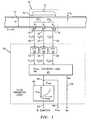
- FIG. 1is a schematic block diagram of a fluid parameter measurement system, in accordance with the present invention.
- FIG. 2is a graph of the speed of sound of a mixture versus the percent water volume fraction for an oil/water mixture, in accordance with the present invention.
- FIG. 3is a transmission matrix model for the acoustics of an example pipe having 9 sections and a radiation impedance ⁇ rad , in accordance with the present invention.
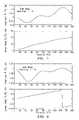
- FIG. 4illustrations (a)-(c), are graphs of axial values for ⁇ mix , a mix , h water properties of a mixture for the segments of the pipe of FIG. 3 , in accordance with the present invention.
- FIG. 5is a graph of magnitude and phase versus frequency for a ratio of two pressures P 1 /P 2 , for radiation impedance of 1.0, water fraction of 50%, and axial properties of FIG. 4 , in accordance with the present invention.
- FIG. 6is a graph of magnitude and phase versus frequency for a ratio of two pressures P 1 /P 3 , for radiation impedance of 1.0, water fraction of 50%, and axial properties of FIG. 4 , in accordance with the present invention.
- FIG. 7is a graph of the magnitude of the speed of sound estimate versus an error term over a range of frequencies, using the frequency responses of FIGS. 5 , 6 , in accordance with the present invention.
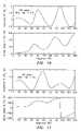
- FIG. 8is a graph of magnitude and phase versus frequency for a ratio of two pressures P 1 /P 2 , for radiation impedance of 0.5, water fraction of 50%, and constant axial properties of the mixture, in accordance with the present invention.
- FIG. 9is a graph of magnitude and phase versus frequency for a ratio of two pressures P 1 /P 3 , for radiation impedance of 0.5, water fraction of 50%, and constant axial properties of the mixture, in accordance with the present invention.
- FIG. 10is a graph of magnitude and phase versus frequency for a ratio of two pressures P 1 /P 2 , for radiation impedance of 0.5, water fraction of 5%, and constant axial properties of the mixture, in accordance with the present invention.
- FIG. 11is a graph of magnitude and phase versus frequency for a ratio of two pressures P 1 /P 3 , for radiation impedance of 0.5, water fraction of 5%, and constant axial properties of the mixture, in accordance with the present invention.
- FIG. 12is a graph of the magnitude of the speed of sound estimate versus an error term over a range of frequencies, using the frequency response for two different percent water fractions, of FIGS. 8-11 , in accordance with the present invention.
- FIG. 13is a contour plot of speed of sound versus axial Mach versus an error term, for 5% water fraction, Mach number of 0.05, at 25 Hz, in accordance with the present invention.
- FIG. 14is a contour plot of speed of sound versus axial Mach versus an error term, for 50% water fraction, Mach number of 0.05, at 25 Hz, in accordance with the present invention.
- FIG. 15is a portion of a logic flow diagram for logic of FIG. 1 , in accordance with the present invention.
- FIG. 16is a continuation of the logic flow diagram of FIG. 15 , in accordance with the present invention.
- FIG. 17is a schematic block diagram of a fluid parameter measurement system, in an industrial process control system, using fiber optic sensors, in accordance with the present invention.
- FIG. 18is a plot of speed of sound against wall thickness of a pipe for a rigid and a non-rigid pipe, in accordance with the present invention.
- FIG. 19is a cross-sectional view of a pipe, showing a plurality of sensors around the circumference of the pipe, in accordance with the present invention.
- FIG. 20is a side view of a pipe having an isolating sleeve around the sensing region of the pipe, in accordance with the present invention.
- FIG. 21is an end view of a pipe showing pressure inside and outside the pipe, in accordance with the present invention.
- FIG. 22is a side view of a pipe having optical fiber wrapped around the pipe at each unsteady pressure measurement location and a pair of Bragg gratings around each optical wrap, in accordance with the present invention.
- FIG. 23is a side view of a pipe having optical fiber wrapped around the pipe at each unsteady pressure measurement location with a single Bragg grating between each pair of optical wraps, in accordance with the present invention.
- FIG. 24is a side view of a pipe having optical fiber wrapped around the pipe at each unsteady pressure measurement location without Bragg gratings around each of the wraps, in accordance with the present invention.
- FIG. 25is an alternative geometry of an optical wrap of FIGS. 21 , 22 , of a radiator tube geometry, in accordance with the present invention.
- FIG. 26is an alternative geometry of an optical wrap of FIGS. 21 , 22 , of a race track geometry, in accordance with the present invention.
- FIG. 27is a side view of a pipe having a pair of gratings at each axial sensing location, in accordance with the present invention.
- FIG. 28is a side view of a pipe having a single grating at each axial sensing location, in accordance with the present invention.
- FIG. 29is a top view of three alternative strain gauges, in accordance with the present invention.
- FIG. 30is a side view of a pipe having three axially spaced strain gauges attached thereto, in accordance with the present invention.
- FIG. 31is an end view of a pipe having three unsteady pressure sensors spaced apart from each other within the pipe, in accordance with the present invention.
- FIG. 32is a side view of a pipe having three unsteady pressure sensors spaced axially within the pipe, in accordance with the present invention.
- FIG. 33is a side view of a pipe having three unsteady pressure sensors axially and radially spaced within the pipe, in accordance with the present invention.
- FIG. 34is a side view of a pipe having an inner tube with axially distributed optical fiber wraps for unsteady pressure sensors, in accordance with the present invention.
- FIG. 35is a side view of a pipe having an inner tube with axially distributed unsteady pressure sensors located along the tube, in accordance with the present invention.
- FIG. 36is a side view of a pipe having an inner tube with three axially distributed hydrophones located within the tube, in accordance with the present invention.
- FIG. 37is a diagram showing the propagation of acoustic waves from a single source in two dimensional space onto a spatial array, in accordance with the present invention.
- FIG. 38is a side view of a pipe having left and right travelling acoustic waves propagating along the pipe, in accordance with the present invention.
- FIG. 39is a diagram showing the propagation of acoustic waves from two sources in two dimensional space onto a spatial array, in accordance with the present invention.
- FIG. 40is a schematic block diagram of an alternative embodiment of a fluid parameter measurement system, in accordance with the present invention.
- FIG. 41is a graph of speed of sound versus water cut, in accordance with the present invention.
- a pipe (or conduit) 12has three acoustic pressure sensors 14 , 16 , 18 , located at three locations x 1 ,x 2 ,x 3 along the pipe 12 .
- the pressuremay be measured through holes in the pipe 12 ported to external pressure sensors or by other techniques discussed hereinafter.
- the pressure sensors 14 , 16 , 18provide pressure time-varying signals P 1 (t),P 2 (t),P 3 (t) on lines 20 , 22 , 24 , to known Fast Fourier Transform (FFT) logics 26 , 28 , 30 , respectively.
- FFTFast Fourier Transform
- the FFT logics 26 , 28 , 30calculate the Fourier transform of the time-based input signals P 1 (t),P 2 (t),P 3 (t) and provide complex frequency domain (or frequency based) signals P 1 ( ⁇ ),P 2 ( ⁇ ),P 3 ( ⁇ ) on lines 32 , 34 , 36 indicative of the frequency content of the input signals.
- any other technique for obtaining the frequency domain characteristics of the signals P 1 (t),P 2 (t),P 3 (t)may be used.
- the cross-spectral density and the power spectral densitymay be used to form a frequency domain transfer functions (or frequency response or ratios) discussed hereinafter.
- logic 60may be implemented in software (using a microprocessor or computer) and/or firmware, or may be implemented using analog and/or digital hardware, having sufficient memory, interfaces, and capacity to perform the functions described herein.
- Acoustic pressure sensors 14 , 16 , 18sense acoustic pressure signals that, as measured, are lower frequency (and longer wavelength) signals than those used for ultrasonic flow meters of the prior art, and thus the current invention is more tolerant to inhomogeneities in the flow.
- the present inventiondiffers from prior art fluid parameter measurement devices in that the present invention incorporates the compliance of the pipe to determine the effective speed of sound of the pipe/fluid system.
- the typical frequency range for acoustic pressure signals of the present inventionis from about 10 Hz to about 10,000 Hz.
- the acoustic pressure signalsare generated within the fluid of the pipe 12 by a variety of non-discrete sources such as remote machinery, pumps, valves, elbows, as well as the fluid flow itself.
- the frequency signals P 1 ( ⁇ ),P 2 ( ⁇ ),P 3 ( ⁇ )are fed to a mix -Mx Calculation Logic 40 which provides a signal on a line 46 indicative of the speed of sound of the mixture a mix (discussed more hereinafter).
- the a mix signalis provided to map (or equation) logic 48 , which converts a mix to a percent composition of the fluid and provides a % Comp signal on a line 50 indicative thereof (as discussed hereinafter).
- the calculation logic 40may also provide a signal Mx on a line 59 indicative of the Mach number Mx (as discussed hereinafter).
- A,Bare the frequency-based complex amplitudes of the right and left traveling waves, respectively
- xis the pressure measurement location along a pipe
- k r ,k lare wave numbers for the right and left travelling waves, respectively, which are defined as:
- Vmixis the axial velocity of the mixture.
- the axial Mach numberrepresents the average velocity of the mixture and the low frequency acoustic field description remains substantially unaltered.
- R ⁇ B Ae i ⁇ ⁇ k r ⁇ x 1 - [ P 1 ⁇ ( ⁇ ) P 2 ⁇ ( ⁇ ) ] ⁇ e - i ⁇ ⁇ k r ⁇ x 2 [ P 1 ⁇ ( ⁇ ) P 2 ⁇ ( ⁇ ) ] ⁇ e i ⁇ ⁇ k l ⁇ x 2 - e i ⁇ ⁇ k l ⁇ x 1 Eq . ⁇ 8 where R is defined as the reflection coefficient.
- Eq. 9may be solved numerically, for example, by defining an “error” or residual term as the magnitude of the left side of Eq. 9, and iterating to minimize the error term.
- the axial velocity of the flow in the pipeis small compared to the speed of sound in the mixture (i.e., the axial Mach number M x is small compared to one).
- the axial velocity of the oil V oil in a typical oil wellis about 10 ft/sec and the speed of sound of oil a oil is about 4,000 ft/sec.
- the speed of sound of the mixture a mix in the pipe 12may be used is to determine the volume fraction of the mixture.
- the speed of sound of a mixture a mix of two fluids (where a fluid is defined herein as a liquid or a gas) in a pipeis in general related to the volume fraction of the two fluids. This relationship may be determined experimentally or analytically.
- the speed of sound of a mixturemay be expressed as follows:
- a mix1 + ⁇ 1 ⁇ 2 ⁇ h 2 h 1 1 a 1 2 + ⁇ 1 ⁇ 2 ⁇ h 2 h 1 ⁇ 1 a 2 2 Eq . ⁇ 12
- a 1 ,a 2are the known speeds of sound
- ⁇ 1 , ⁇ 2are the known densities
- h 1 ,h 2are the volume fractions of the two respective fluids
- a mixis the speed of sound of the mixture
- the densities ⁇ 1 , ⁇ 2 of the two fluidsare within about an order of magnitude (10:1) of each other.
- Other expressions relating the phase fraction to speed of soundmay be used, being derived experimentally, analytically, or computationally.
- a curve 11shows the speed of sound of the mixture a mix plotted as a function of water volume fraction using Eq. 12.
- the subscripts 1,2 of Eq. 12 assigned to the parameters for each fluidis arbitrary provided the notation used is consistent. Thus, if the speed of sound of the mixture a mix is measured, the oil/water fraction may be determined.
- each elementis one meter long.
- an explicit acoustic noise sourcemay or may not be required, as the background acoustic noises within the pipe may provide sufficient excitation to enable a speed of sound measurement from existing ambient acoustic pressures.
- an acoustic noise source(not shown) may be placed at the surface of the well or within the well, provided the source is acoustically coupled to the test section 51 over which the speed of sound is measured.
- FIG. 4illustrations (a)-(c), an example of the axial properties of the mixture in the segments 1 - 9 of the pipe 12 is shown.
- the volume fraction of water h, the speed of sound of the mixture a mix , and the density of the mixture ⁇ mixvary over the length of the pipe 12 and the test segments 5 , 6 (from four to six meters) between the pressure measurements P 1 -P 3 have constant properties.
- the values for ⁇ mix , a mix , h water for sections 1 - 9 , respectively,are shown graphically in FIG.
- the error term of Eq. 10 using the frequency responses of FIGS. 5 , 6is a family of curves, one curve for each frequency ⁇ , where the value of the error is evaluated for values of a mix varied from a water (5,000 ft/sec) to a oil (4,000 ft/sec) at each frequency and the frequency is varied from 5 to 200 Hz in 5 Hz increments. Other frequencies may be used if desired.
- the speed of sound a mix where the error goes to zero (or is minimized)is the same for each frequency ⁇ evaluated. In this case, the error is minimized at a point 70 when a mix is 4335 ft/sec. From FIG.
- an a mix of 4335 ft/seccorresponds to a 50% water volume ratio in the test section that matches the water fraction of the model.
- the sensitivity of a change in a mix to a change in errorvaries based on the evaluation frequency.
- the performancemay be optimized by evaluating a mix at specific low sensitivity frequencies, such frequencies to be determined depending on the specific application and configuration.
- the magnitude of the error term of Eq. 10 using the frequency responses of FIGS. 8 , 9is a family of curves, one curve for each frequency ⁇ , where the value of a mix is varied from a water (5,000 ft/sec) to a oil (4,000 ft/sec) at each frequency and is shown at four frequencies 50,100,150,200 Hz.
- the magnitude and phase of the frequency responsesi.e., the ratio of the frequency based pressure signals
- the magnitude of the error term of Eq. 10 using the frequency responses of FIGS. 10 , 11is a family of dashed curves, one curve for each frequency ⁇ , where the value of a mix is varied from a water (5,000 ft/sec) to a oil (4,000 ft/sec) at each frequency and is shown at four frequencies 50,100,150,200 Hz.
- the sensitivity of a change in a mix to a change in errorvaries based on the evaluation frequency.
- the errorapproaches zero with the largest slope ( ⁇ Error/ ⁇ a mix ) for the 200 Hz curve, thereby making it easier to detect the value where the error goes to zero, and thus the value of a mix .
- 200 Hzwould likely be a robust frequency to use to determine the speed of sound in this example.
- Eq. 10may be solved for k (and thus a mix ) in a closed-form solution as a function of the pressure frequency responses (or frequency based signal ratios) as follows:
- a mix⁇ [ 1 ⁇ ⁇ ⁇ x ] ⁇ i ⁇ ⁇ log ⁇ [ P 12 + P 13 ⁇ P 12 + ( P 12 2 + 2 ⁇ P 13 ⁇ P 12 2 + P 13 2 ⁇ P 12 2 - 4 ⁇ P 13 2 ) 1 / 2 2 ⁇ P 13 ] Eq . ⁇ 14
- P 12P 1 ( ⁇ )/P 2 ( ⁇ )
- P 13P 1 ( ⁇ )/P 3 ( ⁇ )
- iis the square root of ⁇ 1
- the result of the Log[ ] functionis an imaginary number, yielding a real number for the speed of sound a mix .
- the analytical solution to the Eq. 10 shown in Eqs. 13 and 14is valid primarily for the frequencies for which the length of the test section 51 along the pipe 12 (i.e., x 3 ⁇ x 1 or 2 ⁇ x for equally spaced sensors) is shorter than the wavelength ⁇ of the acoustic waves to be measured. This restriction is due to multiple possible solutions to the Eq. 10. Alternative solutions to Eq. 10 for other frequency ranges may be derived using a variety of known techniques.
- P 1 ⁇ ( ⁇ ) + P 3 ⁇ ( ⁇ ) P 2 ⁇ ( ⁇ )A ⁇ ⁇ e - i ⁇ ⁇ kx 1 + B ⁇ ⁇ e + i ⁇ ⁇ kx 1 + A ⁇ ⁇ e - i ⁇ ⁇ kx 3 + B ⁇ ⁇ e + i ⁇ ⁇ kx 3 A ⁇ ⁇ e - i ⁇ ⁇ kx 2 + B ⁇ ⁇ e + i ⁇ ⁇ kx 2 Eq . ⁇ 15
- P 1 ⁇ ( ⁇ ) + P 3 ⁇ ( ⁇ ) P 2 ⁇ ( ⁇ )A + B + A ⁇ ⁇ e - 2 ⁇ ⁇ i ⁇ ⁇ k ⁇ ⁇ ⁇ ⁇ ⁇ x + B ⁇ ⁇ e + 2 ⁇ ⁇ i ⁇ ⁇ k ⁇ ⁇ ⁇ ⁇ ⁇ x A ⁇ ⁇ e - i ⁇ ⁇ k ⁇ ⁇ ⁇ ⁇ ⁇ x + B ⁇ ⁇ e + i ⁇ ⁇ k ⁇ ⁇ ⁇ ⁇ ⁇ x Eq . ⁇ 16
- R ⁇ B A1 - [ P 1 ⁇ ( ⁇ ) P 2 ⁇ ( ⁇ ) ] ⁇ e - i ⁇ ⁇ k ⁇ ⁇ ⁇ ⁇ ⁇ x [ P 1 ⁇ ( ⁇ ) P 2 ⁇ ( ⁇ ) ] ⁇ e i ⁇ ⁇ k ⁇ ⁇ ⁇ ⁇ ⁇ x - 1 Eq . ⁇ 18
- Eq. 23is particularly useful due to its simple geometric form, from which a mix can be easily interpreted.
- a mixcan be determined directly by inspection from a digital signal analyzer (or other similar instrument) set up to provide a display indicative of the left side of Eq. 23, which will be a cosine curve from which a mix may be readily obtained.
- Eq. 23may be used to determine amix using an iterative approach where a measured function is calculated from the left side of Eq. 23 (using the measured pressures) and compared to a cosine curve of the right side of Eq. 23 where amix is varied until it substantially matches the measured function.
- Various other curve fitting, parameter identification, and/or minimum error or solution techniquesmay be used to determine the value of amix that provides the best fit to satisfy Eq. 23.
- FIG. 41a graph of speed of sound (a mix ) versus water cut is shown where a mix is calculated using Eq. 23 as described hereinbefore.
- the line 452shows the theoretical value for water cut based on Eq. 12 and FIG. 2 discussed hereinbefore, and the circles are the calculated values for a mix .
- the value of Mx and a mix where the error term of Eq. 10 is zerocan be uniquely determined from Eq. 10 for a given water fraction.
- Eq. 10for a given % water fraction, there is a unique value indicated by points 90 , 92 for 5% and 50% water cut, respectively.
- the calculation logic 40begins at a step 100 where P 12 is calculated as the ratio of P 1 ( ⁇ )/P 2 ( ⁇ ), and a step 102 where P 13 is calculated as the ratio of P 1 ( ⁇ )/P 3 ( ⁇ ).
- a step 108calculates a mix (n) from the closed form solution of Eq. 14.
- a step 110checks whether the logic 40 has calculated a mix at a predetermined number of frequencies, e.g., ten. If n is not greater than ten, steps 112 , 114 , increments the counter n by one and increases the frequency ⁇ by a predetermined amount (e.g., ten Hz) and the step 108 is repeated.
- a predetermined number of frequenciese.g., ten.
- step 116determines an average value for a mix using the values of a mix (n) over the ten frequencies, and the logic 40 exits.
- a step 132checks whether n is greater than or equal to ten. If not, a step 134 increments n by one and a step 136 increases the frequency ⁇ by a predetermined amount (e.g., 10 Hz) and continues at step 122 as shown in FIG. 15 . If n is greater than or equal to 10, a step 138 calculates an average value for a mix over the ten frequencies, and the logic 40 ends.
- a predetermined amounte.g. 10 Hz
- step 212increases a mix by a predetermined amount (e.g., 1 ft/sec) and the logic goes back to step 206 . If the result of step 210 is yes, a step 214 increases Mx by a predetermined amount (e.g., 1) and the logic goes back to step 204 .
- a predetermined amounte.g. 1 ft/sec
- a predetermined amounte.g. 10 Hz
- a step 224calculates a average values for a mix (n) and Mx(n) at the 10 different frequencies to calculate a mix and Mx, and the logic exists.
- the value for a mix aboveis similar to that shown in FIGS. 13 , 14 , discussed hereinbefore, where the final value of a mix are the points 90 , 92 where the error equals zero.
- a mixmay be calculated by filtering or windowing a mix (n), from predetermined frequencies.
- the number of frequencies and the frequencies evaluatedmay be any desired number and values.
- itmay be calculated at only one frequency.
- the logic shown in FIGS. 15 , 16is one of many possible algorithms to calculate a mix using the teachings herein.
- the compliance (or flexibility) of the pipe 12 (or conduit) in the sensing regionmay influence the accuracy or interpretation of the measured speed of sound a mix of the mixture in two primary ways.
- flexing of the pipe 12 in the sensing regionreduces the measured speed of sound a mix from the sound in an unbounded domain.
- the sound speed in an unbounded domainis a property that is closely linked with the fluid properties.
- the speed of sound of water in an infinitely rigid pipe(i.e., infinite modulus) is indicated by a flat curve 350
- the speed of sound of water in a steel pipeis indicated by a curve 352 .
- a point 354 on the curve 352indicates the value of the speed of sound of about 4768 ft/sec for a Schedule 80 steel pipe. Accordingly, the thicker the pipe wall, the closer the speed of sound approaches the value of 5,000 ft/sec for an infinitely rigid pipe.
- the errors (or boundary effects) shown in FIG. 18 introduced into the measurements by a non-rigid (or compliant) pipe 12can be calibrated and corrected for to accurately determine the speed of sound in the fluid in an unbounded media.
- the system (pipe)does modify the propagation velocity, such velocity can be mapped to the propagation velocity in an infinite media in a predictable fashion.
- the propagation velocity of compression wavesis influenced by the structural properties of the pipe.
- the propagation velocityis related to the infinite fluid domain speed of sound and the structural properties via the following relation:
- Ethe Young's modulus for the pipe material.
- Eq. 26holds primarily for frequencies where the wavelength of the acoustics is long (e.g., greater than about two to one) compared to the diameter of the pipe and for frequencies which are low compared to the natural frequency of the breathing mode of the pipe. Eq. 26 also applies primarily to wavelengths which are long enough such that hoop stiffness dominates the radial deflections of the pipe.
- the curve 352(for 100% water) would be one of a family of curves for various different oil/water mixtures.
- the termsmay be defined in terms of the density of each constituent, and the volumetric phase fraction as follows:
- ⁇ iis the density of the i th constituent of a multi-component mixture
- a iis the sound speed of the i th constituent of the mixture
- ⁇ iis the volumetric phase fraction of the i th constituent of the mixture
- Nis the number of components of the mixture.
- the pipe 12may be desirable for the pipe 12 to exhibit a certain amount of pipe compliance.
- the axial test section 51 of the pipe 12 along where the sensors 14 , 16 , 18 are locatedmay be made as rigid as possible.
- the thickness of the wall 53 of the test section 51may be made to have a predetermined thickness, or the test section 51 may be made of a very rigid material, e.g., steel, titanium, Kevlar®, ceramic, or other material with a high modulus.
- the pipe 12is compliant and acoustically coupled to fluids and materials outside the pipe 12 in the sensing region, such as the annulus fluid, casing, rock formations, etc.
- the acoustic properties of these fluids and materials outside the pipe 12 diametermay influence the measured speed of sound. Because the acoustic properties of such fluids and materials are variable and unknown, their affect on measured speed of sound cannot be robustly corrected by calibration (nor mapped to the propagation velocity in an infinite media in a predictable fashion).
- an outer isolation sleeve 410(or sheath, shell, housing, or cover) which is attached to the outer surface of pipe 12 over where the pressure sensors 14 , 16 , 18 are located on the pipe 12 .
- the sleeve 410forms a closed chamber 412 between the pipe 12 and the sleeve 410 .
- a gassuch as air
- the acoustic energy in the pipeis not acoustically coupled to fluids and materials outside the pipe 12 in the sensing region.
- the speed of soundcan be calibrated to the actual speed of sound in the fluid in the pipe 12 as discussed hereinbefore.
- the sleeve 410is similar to that U.S. application Ser. No. 09/344,070, entitled “Measurement of Propagating Acoustic Waves in Compliant Pipes”, filed Jun. 25, 1999, now U.S. Pat. No. 6,435,030 which is incorporated herein by reference.
- two or more pressure sensorsmay be used around the circumference of the pipe 12 at each of the axial locations x 1 ,x 2 ,x 3 .
- the signals from the pressure sensors, 400 , 402 , 404 , 406 around the circumference at a given axial locationmay be averaged to provide a cross-sectional (or circumference) averaged unsteady acoustic pressure measurement.
- Other numbers of acoustic pressure sensors and annular spacingmay be used.
- Averaging multiple annular pressure sensorsreduces noises from disturbances and pipe vibrations and other sources of noise not related to the one-dimensional acoustic pressure waves in the pipe 12 , thereby creating a spatial array of pressure sensors to help characterize the one-dimensional sound field within the pipe 12 .
- the pressure sensors 14 , 16 , 18 described hereinmay be any type of pressure sensor, capable of measuring the unsteady (or ac or dynamic) pressures within a pipe, such as piezoelectric, optical, capacitive, resistive (e.g., Wheatstone bridge), accelerometers (or geophones), velocity measuring devices, displacement measuring devices, etc. If optical pressure sensors are used, the sensors 14 , 16 , 18 may be Bragg grating based pressure sensors, such as that described in U.S. patent application Ser. No. 08/925,598, entitled “High Sensitivity Fiber Optic Pressure Sensor For Use In Harsh Environments”, filed Sep. 8, 1997, now U.S. Pat. No. 6,016,702.
- the sensors 14 , 16 , 18may be electrical or optical strain gages attached to or embedded in the outer or inner wall of the pipe which measure pipe wall strain, including microphones, hydrophones, or any other sensor capable of measuring the unsteady pressures within the pipe 12 .
- the sensors 14 , 16 , 18may be connected individually or may be multiplexed along one or more optical fibers using wavelength division multiplexing (WDM), time division multiplexing (TDM), or any other optical multiplexing techniques (discussed more hereinafter).
- WDMwavelength division multiplexing
- TDMtime division multiplexing
- the senoris glass based, it is chemically impervious to most industrial process related chemicals. Further, because the sensor of the present invention uses light for signal transmission, it does not require any electrical power and as such is not influenced by electromagnetic fields and cannot create arcing or explosions when used in the presence of flammable vapors. In addition, the sensor of the present invention has no moving parts, such as a, bellows, which makes the device more reliable and less susceptible to system hysteresis found in other mechanical pressure sensors that utilize diaphragms bellows or other displacement type devices.
- a strain gagemay measure the unsteady (or dynamic or ac) pressure variations Pin inside the pipe 12 by measuring the elastic expansion and contraction, as represented by arrows 350 , of the diameter (and thus the circumference as represented by arrows 351 ) of the pipe 12 .
- the strain gageswould measure the pipe wall deflection in any direction in response to unsteady pressure signals inside the pipe 12 .
- the elastic expansion and contraction of pipe 12is measured at the location of the strain gage as the internal pressure P in changes, and thus measures the local strain (axial strain, hoop strain or off axis strain), caused by deflections in the directions indicated by arrows 351 , on the pipe 12 .
- the amount of change in the circumferenceis variously determined by the hoop strength of the pipe 12 , the internal pressure P in , the external pressure P out outside the pipe 12 , the thickness T w of the pipe wall 352 , and the rigidity or modulus of the pipe material.
- the thickness of the pipe wall 352 and the pipe material in the sensor sections 51may be set based on the desired sensitivity of sensors 14 , 16 , 18 , and other factors and may be different from the wall thickness or material of the pipe 12 outside the sensing region 51 .
- an accelerometermay measure the unsteady (or dynamic or ac) pressure variations P in inside the pipe 12 by measuring the acceleration of the surface of pipe 12 in a radial direction, as represented by arrows 350 .
- the acceleration of the surface of pipe 12is measured at the location of the accelerometer as the internal pressure P in changes and thus measures the local elastic dynamic radial response of the wall 352 of the pipe.
- the magnitude of the accelerationis variously determined by the hoop strength of the pipe 12 , the internal pressure P in , the external pressure P out outside the pipe 12 , the thickness T w of the pipe wall 352 , and the rigidity or modulus of the pipe material.
- the thickness of the pipe wall 352 and the pipe material in the sensing section 51may be set based on the desired sensitivity of sensors 14 , 16 , 18 and other factors and may be different from the wall thickness or material of the pipe 12 outside the sensing region 14 .
- the pressure sensors 14 , 16 , 18may comprise a radial velocity or displacement measurement device capable of measuring the radial displacement characteristics of wall 352 of pipe 12 in response to pressure changes caused by unsteady pressure signals in the pipe 12 .
- the accelerometer, velocity or displacement sensorsmay be similar to those described in commonly-owned copending U.S. patent application Ser. No. 09/344,069, entitled “Displacement Based Pressure Sensor Measuring Unsteady Pressure in a Pipe”, filed Jun. 25, 1999, now U.S. Pat. No. 6,463,813 and U.S. patent application Ser. No. 09/344,093 entitled “Non-Intrusive Fiber Optic Pressure Sensor for Measuring Unsteady Pressures within a Pipe”, filed Jun. 25, 1999, now U.S. Pat. No. 6,450,037 and incorporated herein by reference.
- the ac pressure sensors 14 , 16 , 18may be configured using an optical fiber 300 that is coiled or wrapped around and attached to the pipe 12 at each of the pressure sensor locations as indicated by the coils or wraps 302 , 304 , 306 for the pressures P 1 ,P 2 ,P 3 , respectively.
- the fiber wraps 302 , 304 , 306are wrapped around the pipe 12 such that the length of each of the fiber wraps 302 , 304 , 306 changes with changes in the pipe hoop strain in response to unsteady pressure variations within the pipe 12 and thus internal pipe pressure is measured at the respective axial location.
- Each of the wrapsmeasure substantially the circumferentially averaged pressure within the pipe 12 at a corresponding axial location on the pipe 12 . Also, the wraps provide axially averaged pressure over the axial length of a given wrap. While the structure of the pipe 12 provides some spatial filtering of short wavelength disturbances, we have found that the basic principle of operation of the invention remains substantially the same as that for the point sensors described hereinbefore.
- pairs of Bragg gratings( 310 , 312 ),( 314 , 316 ), ( 318 , 320 ) may be located along the fiber 300 at opposite ends of each of the wraps 302 , 304 , 306 , respectively.
- the grating pairsare used to multiplex the pressure signals P 1 ,P 2 ,P 3 to identify the individual wraps from optical return signals.
- the first pair of gratings 310 , 312 around the wrap 302may have a common reflection wavelength ⁇ 1
- the second pair of gratings 314 , 316 around the wrap 304may have a common reflection wavelength ⁇ 2 , but different from that of the first pair of gratings 310 , 312
- the third pair of gratings 318 , 320 around the wrap 306have a common reflection wavelength ⁇ 3 , which is different from ⁇ 1 , ⁇ 2 .
- a series of Bragg gratings 360 , 362 , 364 , 366 with only one grating between each of the wraps 302 , 304 , 306may be used each having a common reflection wavelength ⁇ 1 .
- the wraps 302 , 304 , 306 with the gratings 310 , 312 , 314 , 316 , 318 , 320 ( FIG. 22 ) or with the gratings 360 , 362 , 364 , 366 ( FIG. 23 )may be configured in numerous known ways to precisely measure the fiber length or change in fiber length, such as an interferometric, Fabry Perot, time-of-flight, or other known arrangements.
- time-of-flightor Time-Division-Multiplexing; TDM
- TDMTime-Division-Multiplexing
- the gratings 310 , 312 , 314 , 316 , 318 , 320are shown oriented axially with respect to pipe 12 , in FIGS. 22 , 23 , they may be oriented along the pipe 12 axially, circumferentially, or in any other orientations. Depending on the orientation, the grating may measure deformations in the pipe wall 352 with varying levels of sensitivity. If the grating reflection wavelength varies with internal pressure changes, such variation may be desired for certain configurations (e.g., fiber lasers) or may be compensated for in the optical instrumentation for other configurations, e.g., by allowing for a predetermined range in reflection wavelength shift for each pair of gratings. Alternatively, instead of each of the wraps being connected in series, they may be connected in parallel, e.g., by using optical couplers (not shown) prior to each of the wraps, each coupled to the common fiber 300 .
- optical couplersnot shown
- the sensors 14 , 16 , 18may also be formed as a purely interferometric sensor by wrapping the pipe 12 with the wraps 302 , 304 , 306 without using Bragg gratings where separate fibers 330 , 332 , 334 may be fed to the separate wraps 302 , 304 , 306 , respectively.
- known interferometric techniquesmay be used to determine the length or change in length of the fiber 10 around the pipe 12 due to pressure changes, such as Mach Zehnder or Michaelson Interferometric techniques, such as those set forth in U.S. patent application Ser. No.
- the wraps 302 , 304 , 306may have alternative geometries, such as a “radiator coil” geometry ( FIG. 25 ) or a “race-track” geometry ( FIG. 26 ), which are shown in a side view as if the pipe 12 is cut axially and laid flat.
- the wraps 302 - 206are not necessarily wrapped 360 degrees around the pipe, but may be disposed over a predetermined portion of the circumference of the pipe 12 , and have a length long enough to optically detect the changes to the pipe circumference.
- wrapsmay be used if desired. Also, for any geometry of the wraps described herein, more than one layer of fiber may be used depending on the overall fiber length desired.
- the desired axial length of any particular wrapis set depending on the characteristics of the ac pressure desired to be measured, for example the axial length of the pressure disturbance caused by a vortex to be measured.
- embodiments of the present inventioninclude configurations wherein instead of using the wraps 302 , 304 , 306 , the fiber 300 may have shorter sections that are disposed around at least a portion of the circumference of the pipe 12 that can optically detect changes to the pipe circumference. It is further within the scope of the present invention that sensors may comprise an optical fiber 300 disposed in a helical pattern (not shown) about pipe 12 . As discussed herein above, the orientation of the strain sensing element will vary the sensitivity to deflections in pipe wall 352 deformations caused by unsteady pressure signals in the pipe 12 .
- the pairs of Bragg gratings( 310 , 312 ), ( 314 , 316 ), ( 318 , 320 ) are located along the fiber 300 with sections 380 , 382 , 384 of the fiber 300 between each of the grating pairs, respectively.
- known Fabry Perot, interferometric, time-of-flight or fiber laser sensing techniquesmay be used to measure the strain in the pipe.
- individual gratings 370 , 372 , 374may be disposed on the pipe and used to sense the unsteady variations in strain in the pipe 12 (and thus the unsteady pressure within the pipe) at the sensing locations.
- the grating reflection wavelength shiftwill be indicative of changes in pipe diameter and thus pressure.
- optical strain gageAny other technique or configuration for an optical strain gage may be used.
- the type of optical strain gage technique and optical signal analysis approachis not critical to the present invention, and the scope of the invention is not intended to be limited to any particular technique or approach.
- the pressure sensorsincluding electrical strain gages, optical fibers and/or gratings among others as described herein, may be attached to the pipe by adhesive, glue, epoxy, tape or other suitable attachment means to ensure suitable contact between the sensor and the pipe 12 .
- the sensorsmay alternatively be removable or permanently attached via known mechanical techniques, such as mechanical fastener, spring loaded, clamped, clam shell arrangement, strapping or other equivalents.
- the strain gages, including optical fibers and/or gratingsmay be embedded in a composite pipe. If desired, for certain applications, the gratings may be detached from (or strain or acoustically isolated from) the pipe 12 if desired.
- any other strain sensing techniquemay be used to measure the variations in strain in the pipe, such as highly sensitive piezoelectric, electronic or electric, strain gages attached to or embedded in the pipe 12 .
- FIG. 29different known configurations of highly sensitive piezoelectric strain gages are shown and may comprise foil type gages.
- FIG. 30an embodiment of the present invention is shown wherein pressure sensors 14 , 16 , 18 comprise strain gages 340 .
- strain gages 340are disposed about a predetermined portion of the circumference of pipe 12 . The axial placement of and separation distance ⁇ X 1 , ⁇ X 2 between the pressure sensors 14 , 16 , 18 are determined as described herein above.
- the inventionwill also work when the unsteady pressures are measured inside the pipe 12 .
- the pressure sensors 14 , 16 , 18 that measure the pressures P 1 ,P 2 ,P 3may be located anywhere within the pipe 12 and any technique may be used to measure the unsteady pressures inside the pipe 12 .
- the inventionmay also measure the speed of sound of a mixture flowing outside a pipe or tube 425 .
- the tube 425may be placed within the pipe 12 and the pressures P 1 -P 3 measured at the outside of the tube 425 .
- Any techniquemay be used to measure the unsteady pressures P 1 -P 3 outside the tube 425 .
- the tube 425may have the optical wraps 302 , 304 , 306 wrapped around the tube 425 at each sensing location.
- any of the strain measurement or displacement, velocity or accelerometer sensors or techniques described hereinmay be used on the tube 425 .
- the pressures P 1 -P 3may be measured using direct pressure measurement sensors or techniques described herein. Any other type of unsteady pressure sensors 14 , 16 , 18 may be used to measure the unsteady pressures within the pipe 12 .
- hydrophones 430 , 432 , 434may be used to sense the unsteady pressures within the pipe 12 .
- the hydrophones 430 , 432 , 434may be located in the tube 425 for ease of deployment or for other reasons.
- the hydrophones 430 , 432 , 434may be fiber optic, electronic, piezoelectric or other types of hydrophones. If fiber optic hydrophones are used, the hydrophones 430 , 432 , 434 may be connected in series or parallel along the common optical fiber 300 .
- the tube 425may be made of any material that allows the unsteady pressure sensors to measure the pressures P 1 -P 3 and may be hollow, solid, or gas filled or fluid filled.
- a dynamic pressure sensoris described in co-pending commonly-owned U.S. patent application Ser. No. 09/326,097 entitled “Mandrel Wound Fiber Optic Pressure Sensor”, filed Jun. 4, 1999, U.S. Pat. No. 6,233,374.
- the end 422 of the tube 425is closed and thus the flow path would be around the end 422 as indicated by lines 424 .
- the tube 425may be coiled tubing or equivalent deployment tool having the pressure sensors 14 , 16 , 18 for sensing P 1 -P 3 inside the tubing 425 .
- the tube 425may also include a bluff or rounded shaped end as indicated by dashed line 420 .
- the sensing section 51may be connected to or part of process tubing 502 (analogous to the pipe 12 in the test section 51 ) within an industrial process control system 500 .
- the isolation sleeve 410may be located over the sensors 14 , 16 , 18 as discussed hereinbefore and attached to the pipe 502 at the axial ends to protect the sensors 14 , 16 , 18 (or fibers) from damage during deployment, use, or retrieval, and/or to help isolate the sensors from acoustic external pressure effects that may exist outside the pipe 502 , and/or to help isolate ac pressures in the pipe 502 from ac pressures outside the pipe 502 .
- the advantages and effect of the isolation sleeve 410are described in commonly owned copending U.S. patent application Ser. No. 09/344,070, entitled “Measurement of Propagating Acoustic Waves in Compliant Pipes”, now U.S. Pat. No. 6,435,030 incorporated herein by reference in its entirety.
- the sensors 14 , 16 , 18are connected to a cable 506 which may comprise the optical fiber 300 (FIGS. 22 , 23 , 27 , 28 ) and is connected to a transceiver/converter 510 of the control system 500 .
- the transceiver/converter 510may be used to receive and transmit optical signals 504 to the sensors 14 , 16 , 18 and provides output signals indicative of the pressure P 1 -P 3 at the sensors 14 , 16 , 18 on the lines, 20 , 22 , 24 , respectively. Also, the transceiver/converter 510 may be part of the Fluid Parameter Logic 60 . The transceiver/converter 510 may be any device that performs the corresponding functions described herein.
- the transceiver/converter 510 together with the optical sensors described hereinbeforemay use any type of optical grating-based measurement technique, e.g., scanning interferometric, scanning Fabry Perot (resonator, cavity, interferometer or other known Fabry Perot arrangement), acousto-optic-tuned filter (AOTF), optical filter, time-of-flight, and may use WDM and/or TDM, etc., having sufficient sensitivity to measure the ac pressures within the pipe.
- any type of optical grating-based measurement techniquee.g., scanning interferometric, scanning Fabry Perot (resonator, cavity, interferometer or other known Fabry Perot arrangement), acousto-optic-tuned filter (AOTF), optical filter, time-of-flight, and may use WDM and/or TDM, etc., having sufficient sensitivity to measure the ac pressures within the pipe.
- a plurality of the sensors 10 of the present inventionmay be connected to a common cable and multiplexed together using any known multiplexing technique by connecting end 511 to other sensors (not shown).
- the various embodiments of the sensor 10 of the present inventioninclude the capability being multiplexed as well as capable of communication with various protocols and systems currently in use in the industrial sensing area.
- FIG. 17there is shown a portion of a process control system 500 incorporating a sensor 10 in accordance with the present invention.
- Fluid parameter logic 510communicates signals Mx, amix, and % Composition along lines 59 , 46 , 50 to control device 70 , a computer or micro-processor, for example, where the information may be used to control the fluid characteristics in pipe 502 through known controls means, such as a pump, valve, throttle, etc. (not shown).
- control system 500and with appropriate electro-optical conversion of the sensor return signal to a conventional 4-20 mA signal the signal can be combined with other control devices and sensors at control device 70 via separate electrical lines.
- the communication from the fiber optic sensoris performed with a 4-20 mA analog signal, and the open protocol HART®. (Highway Addressable Remote Transducer) digital communications format.
- communication from the fiber optic sensor 10may also be performed with open and interoperable protocol FOUNDATIONTM Fieldbus that provides a digital communication link among intelligent field level and control devices via electrical lines.
- the control device 70can be configured for use with other process protocols, including Device Bus, Sensor Bus, Profibus, the ethernet, and others in use throughout the world.
- the use of feedthroughs 511make the sensor 10 of the present invention uniquely qualified for industrial applications requiring multiple sensors.
- the use of sensors having feedthroughs in a large multi-point processenables connectivity to the multiple sensors through a single fiber optic cable.
- Electronic sensors of the prior artrequire dedicated wiring to the sensor and back to the instrumentation. For instance, a typical industrial process control system that utilizes electronic flowmeters of the prior art requires an electrical process loop to facilitate both a power signal to the transmitters and bi-directional communication, and can be constructed in accordance with a number of the aforementioned process communication protocols.
- industrial process uses for the present inventioninclude reverse osmosis, coking, general refining uses, in-line pressure sensors for emissions monitoring, sensors for monitoring hydrogen, combustion control, gas composition analysis, distributed sensors in tank gauging, multi-phase computational fluid dynamics, instrumentation of multiphase flows, among others.
- the present inventioncan be used to measure fluid volume fractions of a mixture of any number of fluids in which the speed of sound of the mixture a mix is related to (or is substantially determined by), the volume fractions of two constituents of the mixture, e.g., oil/water, oil/gas, water/gas.
- the present inventioncan be used to measure the speed of sound of any mixture and can then be used in combination with other known quantities to derive phase content of mixtures with multiple (more than two) constituents.
- the present inventioncan be used to measure any parameter (or characteristic) of any mixture of one or more fluids in which such parameter is related to the speed of sound of the mixture a mix , e.g., fluid fraction, temperature, salinity, mineral content, sand particles, slugs, pipe properties, etc. or any other parameter of the mixture that is related to the speed of sound of the mixture.
- the logic 48FIG. 1
- the inventionwill work independent of the direction of the flow or the amount of flow of the fluid(s) in the pipe, and whether or not there is flow in the pipe. Also, independent of the location, characteristics and/or direction(s) of propagation of the source of the acoustic pressures. Also, instead of a pipe, any conduit or duct for carrying a fluid may be used if desired.
- equations similar to Eqs. 9,10may be derived by obtaining the ratios of any other two pairs of pressures, provided the system of equations Eq. 5-7 are solved for B/A or A/B and the ratio of two pairs of pressures. Also, the equations shown herein may be manipulated differently to achieve the same result as that described herein.
- Eqs. 5,6,7may be written in the form of Eq. 1 in the time-domain giving time domain equations P 1 (x 1 ,t), P 2 (x 2 ,t),P 3 (x 3 ,t), and solved for the speed of sound a mix and eliminating the coefficients A,B using known time domain analytical and signal processing techniques (e.g., convolution).
- acoustic signalsrefers to substantially stochastic, time stationary signals, which have average (or RMS) statistical properties that do not significantly vary over a predetermined period of time (i.e., non-transient ac signals).
- the procedure for determining the one dimensional speed of sound a mix within a fluid contained in a pipe using an array of unsteady pressure measurementsis similar to a problem encountered in underwater acoustics (e.g., SONAR or Sound Navigation Ranging).
- underwater acousticse.g., SONAR or Sound Navigation Ranging
- axial arrays of sensorsare deployed to determine the bearing (or direction) of underwater noise sources.
- the processis referred to as “beam forming”.
- free spacei.e., in an unbounded media, such as the ocean, the speed at which a sound wave propagates along an axial array is dependent on both (1) the free-space speed of sound and (2) the incident angle of the sound wave on the axial array.
- ⁇90 ⁇
- k xr( sin ⁇ ⁇ ⁇ 1 ) ⁇ ⁇ a .
- k xl( sin ⁇ ⁇ ⁇ 2 ) ⁇ ⁇ a .
- the data from the array of sensorsmay be processed in any domain, including the frequency/spatial domain (such as Eq. 4), the temporal/spatial domain (such as Eq. 1), the temporal/wave-number domain or the wave-number/frequency (k- ⁇ ) domain.
- Eq. 4the frequency/spatial domain
- Eq. 1the temporal/spatial domain
- k- ⁇the wave-number/frequency domain
- Eq. 5can be represented in the k- ⁇ domain by taking the spatial Fourier transform of Eq. 5, resulting in the following k- ⁇ representation:
- kis the wave number
- ⁇is the Dirac delta function, which shows a spatial/temporal mapping of the acoustic field in the k- ⁇ plane.
- any technique known in the art for using a spatial (or phased) array of sensors to determine the direction of an acoustic source in three dimensional sound field with a known speed of soundmay be used to solve for the sound speed knowing the direction of travel of the acoustic waves, i.e., axially along the pipe.
- spatial array processing for SONAR arrays, RADAR (RAdio Detecting And Ranging) arrays or other arrays, beam forming, or other signal processing techniquesmay be used to solve for the sound speed knowing the direction of travel of the acoustic waves, i.e., axially along the pipe.
- the fluid parameter logic 60may comprise spatial array processing logic 450 which receives the spatial array of acoustic pressure signals P 1 (t), P 2 (t), P 3 (t) and performs the spatial array processing described herein to determine the speed of sound a mix on the line 46 .
- signal processing logic 60may contain simple look-up tables that include values of various parameters of fluids dependant on sound speed, such as the fluid type. Once the fluid density is determined the fluid type may be ascertained and reported by signal processing logic 60 .
- the flowmeter of the present inventioninclude determining the heating value of a fluid, the acid strength of sulfuric acid solution (or other acid or caustic mixture), the steam quality of a fluid, the salinity of fluid mixture, determining the phrase fraction for a three phase mixture and other known or contemplated uses where the sound speed and density of the fluid mixture yield powerful insight in determining other fluid values and compositions.
Landscapes
- Physics & Mathematics (AREA)
- General Physics & Mathematics (AREA)
- Chemical & Material Sciences (AREA)
- Pathology (AREA)
- Health & Medical Sciences (AREA)
- Analytical Chemistry (AREA)
- Biochemistry (AREA)
- General Health & Medical Sciences (AREA)
- Life Sciences & Earth Sciences (AREA)
- Immunology (AREA)
- Engineering & Computer Science (AREA)
- Signal Processing (AREA)
- Acoustics & Sound (AREA)
- Mathematical Physics (AREA)
- Spectroscopy & Molecular Physics (AREA)
- Investigating Or Analyzing Materials By The Use Of Ultrasonic Waves (AREA)
- Measuring Fluid Pressure (AREA)
- Measurement Of Mechanical Vibrations Or Ultrasonic Waves (AREA)
- Measuring Volume Flow (AREA)
Abstract
Description
P(x,t)=(Ae−ik
where A,B are the frequency-based complex amplitudes of the right and left traveling waves, respectively, x is the pressure measurement location along a pipe, ω is frequency (in rad/sec, where ω=2πf), and kr,klare wave numbers for the right and left travelling waves, respectively, which are defined as:
where amixis the speed of sound of the mixture in the pipe, ω is frequency (in rad/sec), and Mxis the axial Mach number of the flow of the mixture within the pipe, where:
where Vmix is the axial velocity of the mixture. For non-homogenous mixtures, the axial Mach number represents the average velocity of the mixture and the low frequency acoustic field description remains substantially unaltered.
P(x,ω)=Ae−ik
P1(ω)=P(x=x1,ω)=Ae−ik
P2(ω)=P(x=x2,ω)=Ae−ik
P3(ω)=P(x=x3,ω)=Ae−ik
where, for a given frequency, A and B are arbitrary constants describing the acoustic field between the
where R is defined as the reflection coefficient.
where R=B/A is defined by Eq. 8 and kr and kl are related to amixas defined by Eq. 2. Eq. 9 may be solved numerically, for example, by defining an “error” or residual term as the magnitude of the left side of Eq. 9, and iterating to minimize the error term.
and the distinction between the wave numbers for the right and left traveling waves is eliminated. In that case (where Mx is negligible), since all of the variables in Eq. 10 are known except for amix, the value for amixcan be iteratively determined by evaluating the error term at a given frequency ω and varying amixuntil the error term goes to zero. The value of amixat which the magnitude of the error term equals zero (or is a minimum), corresponds to the correct value of the speed of sound of the mixture amix. As Eq. 10 is a function of frequency ω, the speed of sound amixat which the error goes to zero is the same for each frequency ω evaluated (discussed more hereinafter). However, in practice, there may be some variation over certain frequencies due to other effects, e.g., pipe modes, non-acoustical pressure perturbation, discretization errors, etc., which may be filtered, windowed, averaged, etc. if desired (discussed more hereinafter). Furthermore, since each frequency is an independent measurement of the same parameter, the multiple measurements may be weighted averaged or filtered to provide a single more robust measurement of the speed of sound.
where a1,a2are the known speeds of sound, ρ1,ρ2are the known densities, and h1,h2are the volume fractions of the two respective fluids, amixis the speed of sound of the mixture, and the densities ρ1,ρ2of the two fluids are within about an order of magnitude (10:1) of each other. Other expressions relating the phase fraction to speed of sound may be used, being derived experimentally, analytically, or computationally.
Density (ρ): ρwater=1,000 kg/m3; ρoil=700 kg/m3
Speed of sound (a): awater=5,000 ft/sec; aoil=4,000 ft/sec.
The
hwater=0.1, 0.2, 0.3, 0.4, 0.5, 0.6, 0.7, 0.8, 0.9;
ρmix=730, 760, 790, 820, 850, 850, 910, 940, 970 (kg/m3);
amix=4053, 4111, 4177, 4251, 4334, 4334, 4539, 4667, 4818 (ft/sec);
Solving for amix, gives:
where P12=P1(ω)/P2(ω), P13=P1(ω)/P3(ω), i is the square root of −1, and the result of the Log[ ] function is an imaginary number, yielding a real number for the speed of sound amix.
where R=B/A is defined by Eq. 8 with x1=0,x2=Δx, which gives:
where P32=P3(ω)/P2(ω) and P12=P1(ω)/P2(ω).
P(x,y,t)=Aeiω(t−x sin γ
P(x,y=0,t)=Aeiω(t−x sin γ
P(x,t)=Ae−ik
P(x,t)=Be+ik
P(x,t)=Ae−ik
which is the same as Eq. 1, and which may be used to determine the speed of sound by using the sensors described herein and solving the associated equations Eq. 5-7 shown hereinbefore. The same result may also be shown from sources originating in three dimensional space using cylindrical or other coordinate systems.
where k is the wave number and δ is the Dirac delta function, which shows a spatial/temporal mapping of the acoustic field in the k-ω plane.
Claims (12)
Priority Applications (1)
| Application Number | Priority Date | Filing Date | Title |
|---|---|---|---|
| US11/295,250US7322245B2 (en) | 1998-06-26 | 2005-12-05 | Apparatus and method for measuring a fluid flowing in a pipe using acoustic pressures |
Applications Claiming Priority (5)
| Application Number | Priority Date | Filing Date | Title |
|---|---|---|---|
| US10553498A | 1998-06-26 | 1998-06-26 | |
| US09/344,094US6354147B1 (en) | 1998-06-26 | 1999-06-25 | Fluid parameter measurement in pipes using acoustic pressures |
| US10/007,749US6732575B2 (en) | 1998-06-26 | 2001-11-08 | Fluid parameter measurement for industrial sensing applications using acoustic pressures |
| US10/842,068US6988411B2 (en) | 1998-06-26 | 2004-05-10 | Fluid parameter measurement for industrial sensing applications using acoustic pressures |
| US11/295,250US7322245B2 (en) | 1998-06-26 | 2005-12-05 | Apparatus and method for measuring a fluid flowing in a pipe using acoustic pressures |
Related Parent Applications (1)
| Application Number | Title | Priority Date | Filing Date |
|---|---|---|---|
| US10/842,068ContinuationUS6988411B2 (en) | 1998-06-26 | 2004-05-10 | Fluid parameter measurement for industrial sensing applications using acoustic pressures |
Publications (2)
| Publication Number | Publication Date |
|---|---|
| US20060144148A1 US20060144148A1 (en) | 2006-07-06 |
| US7322245B2true US7322245B2 (en) | 2008-01-29 |
Family
ID=26802679
Family Applications (4)
| Application Number | Title | Priority Date | Filing Date |
|---|---|---|---|
| US10/007,749Expired - LifetimeUS6732575B2 (en) | 1998-06-26 | 2001-11-08 | Fluid parameter measurement for industrial sensing applications using acoustic pressures |
| US10/060,114Expired - LifetimeUS6862920B2 (en) | 1998-06-26 | 2002-01-29 | Fluid parameter measurement in pipes using acoustic pressures |
| US10/842,068Expired - LifetimeUS6988411B2 (en) | 1998-06-26 | 2004-05-10 | Fluid parameter measurement for industrial sensing applications using acoustic pressures |
| US11/295,250Expired - Fee RelatedUS7322245B2 (en) | 1998-06-26 | 2005-12-05 | Apparatus and method for measuring a fluid flowing in a pipe using acoustic pressures |
Family Applications Before (3)
| Application Number | Title | Priority Date | Filing Date |
|---|---|---|---|
| US10/007,749Expired - LifetimeUS6732575B2 (en) | 1998-06-26 | 2001-11-08 | Fluid parameter measurement for industrial sensing applications using acoustic pressures |
| US10/060,114Expired - LifetimeUS6862920B2 (en) | 1998-06-26 | 2002-01-29 | Fluid parameter measurement in pipes using acoustic pressures |
| US10/842,068Expired - LifetimeUS6988411B2 (en) | 1998-06-26 | 2004-05-10 | Fluid parameter measurement for industrial sensing applications using acoustic pressures |
Country Status (8)
| Country | Link |
|---|---|
| US (4) | US6732575B2 (en) |
| EP (1) | EP1090274B1 (en) |
| CN (1) | CN1192213C (en) |
| AU (1) | AU746996B2 (en) |
| CA (1) | CA2335457C (en) |
| NO (1) | NO335917B1 (en) |
| RU (1) | RU2250438C9 (en) |
| WO (1) | WO2000000793A1 (en) |
Cited By (18)
| Publication number | Priority date | Publication date | Assignee | Title |
|---|---|---|---|---|
| US20080127728A1 (en)* | 2006-11-30 | 2008-06-05 | General Electric Company | Mechanical response based detonation velocity measurement system |
| US20090006008A1 (en)* | 2007-06-28 | 2009-01-01 | Abhinav Singh Rawat | Apparatus and method for measuring liquid and gas flow rates in a stratified multi-phase flow |
| US20090055104A1 (en)* | 2007-08-24 | 2009-02-26 | Expro Meters, Inc. | Velocity and impingement method for determining parameters of a particle/fluid flow |
| US20090158858A1 (en)* | 2007-12-20 | 2009-06-25 | Expro Meters, Inc. | Method for quantifying varying propagation characteristics of normal incident ultrasonic signals as used in correlation based flow measurement |
| US20090255345A1 (en)* | 2008-04-11 | 2009-10-15 | Expro Meters, Inc. | Clamp-on apparatus for measuring a fluid flow that includes a protective sensor housing |
| CN101567695A (en)* | 2008-04-25 | 2009-10-28 | 汤姆森许可贸易公司 | Method for encoding a sequence of integers, storage device and signal carrying an encoded integer sequence and method for decoding a sequence of integers |
| US20100257941A1 (en)* | 2008-04-10 | 2010-10-14 | Expro Meters, Inc. | Apparatus for attenuating ultrasonic waves propagating within a pipe wall |
| US20100316964A1 (en)* | 2009-06-11 | 2010-12-16 | Alstom Technology Ltd | Solids flow meter for integrated boiler control system |
| US20100332154A1 (en)* | 2007-07-24 | 2010-12-30 | Cidra Corporate Services Inc. | Velocity Based Method for Determining Air-Fuel Ratio of a Fluid Flow |
| US8286466B2 (en) | 2008-06-05 | 2012-10-16 | Expro Meters, Inc. | Method and apparatus for making a water cut determination using a sequestered liquid-continuous stream |
| US20120272737A1 (en)* | 2009-07-24 | 2012-11-01 | Wayne Rudd | Method for determining speed of a signal species in a medium and associated apparatus |
| US8346491B2 (en) | 2007-02-23 | 2013-01-01 | Expro Meters, Inc. | Sonar-based flow meter operable to provide product identification |
| WO2014062818A2 (en) | 2012-10-16 | 2014-04-24 | Expro Meters, Inc. | Systems and methods for managing hydrocarbon material producing wellsites using clamp-on flow meters |
| US8942529B2 (en) | 2008-10-03 | 2015-01-27 | Schlumberger Technology Corporation | Fibre optic tape assembly |
| US20170082484A1 (en)* | 2009-05-27 | 2017-03-23 | Silixa Ltd. | Method and apparatus for optical sensing |
| US10173885B2 (en) | 2016-03-07 | 2019-01-08 | Gilbarco Inc. | Fuel dispenser having acoustic waves coriolis flow meter |
| US10703622B2 (en) | 2017-01-20 | 2020-07-07 | Gillbarco Inc. | Fuel dispenser with a fuel analyzer |
| US20210356307A1 (en)* | 2020-05-15 | 2021-11-18 | Expro Meters, Inc. | Method for determining a fluid flow parameter within a vibrating tube |
Families Citing this family (176)
| Publication number | Priority date | Publication date | Assignee | Title |
|---|---|---|---|---|
| RU2250438C9 (en) | 1998-06-26 | 2005-08-27 | Сидрэ Копэрейшн | Method and device for measuring parameters of fluids in pipes |
| US6463813B1 (en) | 1999-06-25 | 2002-10-15 | Weatherford/Lamb, Inc. | Displacement based pressure sensor measuring unsteady pressure in a pipe |
| US6536291B1 (en) | 1999-07-02 | 2003-03-25 | Weatherford/Lamb, Inc. | Optical flow rate measurement using unsteady pressures |
| US6691584B2 (en) | 1999-07-02 | 2004-02-17 | Weatherford/Lamb, Inc. | Flow rate measurement using unsteady pressures |
| US6601458B1 (en) | 2000-03-07 | 2003-08-05 | Weatherford/Lamb, Inc. | Distributed sound speed measurements for multiphase flow measurement |
| US9772311B2 (en) | 2000-07-14 | 2017-09-26 | Acosense Ab | Active acoustic method for predicting properties of process fluids comprising solid particles or gas/liquid volumes based on their size distribution and concentration |
| SE516861C3 (en) | 2000-07-14 | 2002-04-17 | Abb Ab | Raffinörstryrning |
| US6550342B2 (en) | 2000-11-29 | 2003-04-22 | Weatherford/Lamb, Inc. | Circumferential strain attenuator |
| US6782150B2 (en)* | 2000-11-29 | 2004-08-24 | Weatherford/Lamb, Inc. | Apparatus for sensing fluid in a pipe |
| US6587798B2 (en)* | 2000-12-04 | 2003-07-01 | Weatherford/Lamb, Inc. | Method and system for determining the speed of sound in a fluid within a conduit |
| US6609069B2 (en)* | 2000-12-04 | 2003-08-19 | Weatherford/Lamb, Inc. | Method and apparatus for determining the flow velocity of a fluid within a pipe |
| US6898541B2 (en)* | 2000-12-04 | 2005-05-24 | Weatherford/Lamb, Inc. | Method and apparatus for determining component flow rates for a multiphase flow |
| EP1248082B1 (en)* | 2001-04-06 | 2010-09-01 | Thales Underwater Systems Limited | Fiber optic accelerometer for measuring fluid flow rate |
| NO325098B1 (en) | 2001-04-06 | 2008-02-04 | Thales Underwater Systems Uk L | Apparatus and method for fluid flow grinding by fiber optic detection of mechanical vibrations |
| DE10151253C1 (en)* | 2001-10-17 | 2002-11-14 | Stiebel Eltron Gmbh & Co Kg | Hot water supply operating method uses flow noise for identifying operated hot water tap with corresponding regulation of water temperature |
| US6698297B2 (en) | 2002-06-28 | 2004-03-02 | Weatherford/Lamb, Inc. | Venturi augmented flow meter |
| US6971259B2 (en)* | 2001-11-07 | 2005-12-06 | Weatherford/Lamb, Inc. | Fluid density measurement in pipes using acoustic pressures |
| US7059172B2 (en) | 2001-11-07 | 2006-06-13 | Weatherford/Lamb, Inc. | Phase flow measurement in pipes using a density meter |
| US20030101819A1 (en)* | 2001-12-04 | 2003-06-05 | Mutz Mitchell W. | Acoustic assessment of fluids in a plurality of reservoirs |
| US7474966B2 (en)* | 2002-01-23 | 2009-01-06 | Expro Meters. Inc | Apparatus having an array of piezoelectric film sensors for measuring parameters of a process flow within a pipe |
| US7275421B2 (en) | 2002-01-23 | 2007-10-02 | Cidra Corporation | Apparatus and method for measuring parameters of a mixture having solid particles suspended in a fluid flowing in a pipe |
| US7359803B2 (en)* | 2002-01-23 | 2008-04-15 | Cidra Corporation | Apparatus and method for measuring parameters of a mixture having solid particles suspended in a fluid flowing in a pipe |
| US7328624B2 (en) | 2002-01-23 | 2008-02-12 | Cidra Corporation | Probe for measuring parameters of a flowing fluid and/or multiphase mixture |
| CA2474071C (en)* | 2002-01-23 | 2012-09-18 | Cidra Corporation | Apparatus and method for measuring parameters of a mixture having solid particles suspended in a fluid flowing in a pipe |
| US7032432B2 (en)* | 2002-01-23 | 2006-04-25 | Cidra Corporation | Apparatus and method for measuring parameters of a mixture having liquid droplets suspended in a vapor flowing in a pipe |
| CA2486732C (en)* | 2002-04-10 | 2012-10-02 | Cidra Corporation | Probe for measuring parameters of a flowing fluid and/or multiphase mixture |
| US7395711B2 (en)* | 2002-05-06 | 2008-07-08 | Battelle Memorial Institute | System and technique for characterizing fluids using ultrasonic diffraction grating spectroscopy |
| AU2003255235A1 (en) | 2002-08-08 | 2004-02-25 | Cidra Corporation | Apparatus and method for measuring multi-phase flows in pulp and paper industry applications |
| EP1567833A2 (en)* | 2002-11-12 | 2005-08-31 | CiDra Corporation | An apparatus having an array of piezoelectric film sensors for measuring parameters of a process flow within a pipe |
| US7165464B2 (en)* | 2002-11-15 | 2007-01-23 | Cidra Corporation | Apparatus and method for providing a flow measurement compensated for entrained gas |
| WO2004048906A2 (en)* | 2002-11-22 | 2004-06-10 | Cidra Corporation | Method for calibrating a flow meter having an array of sensors |
| WO2004063741A2 (en)* | 2003-01-13 | 2004-07-29 | Cidra Corporation | Apparatus for measuring parameters of a flowing multiphase fluid mixture |
| DE602004029008D1 (en) | 2003-01-13 | 2010-10-21 | Expro Meters Inc | APPARATUS AND METHOD FOR DETERMINING THE SPEED OF A FLUID IN A PIPE USING ULTRASONIC SENSORS |
| US7086278B2 (en) | 2003-01-21 | 2006-08-08 | Cidra Corporation | Measurement of entrained and dissolved gases in process flow lines |
| US7028543B2 (en)* | 2003-01-21 | 2006-04-18 | Weatherford/Lamb, Inc. | System and method for monitoring performance of downhole equipment using fiber optic based sensors |
| US6945095B2 (en)* | 2003-01-21 | 2005-09-20 | Weatherford/Lamb, Inc. | Non-intrusive multiphase flow meter |
| US7058549B2 (en)* | 2003-01-21 | 2006-06-06 | C1Dra Corporation | Apparatus and method for measuring unsteady pressures within a large diameter pipe |
| WO2004065913A2 (en)* | 2003-01-21 | 2004-08-05 | Cidra Corporation | An apparatus and method of measuring gas volume fraction of a fluid flowing within a pipe |
| US7343818B2 (en)* | 2003-01-21 | 2008-03-18 | Cidra Corporation | Apparatus and method of measuring gas volume fraction of a fluid flowing within a pipe |
| US20060048583A1 (en)* | 2004-08-16 | 2006-03-09 | Gysling Daniel L | Total gas meter using speed of sound and velocity measurements |
| EP1599705B1 (en)* | 2003-03-04 | 2019-01-02 | CiDra Corporation | An apparatus having a multi-band sensor assembly for measuring a parameter of a fluid flow flowing within a pipe |
| US6986276B2 (en) | 2003-03-07 | 2006-01-17 | Weatherford/Lamb, Inc. | Deployable mandrel for downhole measurements |
| US6837098B2 (en) | 2003-03-19 | 2005-01-04 | Weatherford/Lamb, Inc. | Sand monitoring within wells using acoustic arrays |
| DE10323483A1 (en)* | 2003-05-23 | 2004-12-30 | Robert Bosch Gmbh | Device for determining a relative speed between a vehicle and an impact object |
| US7197942B2 (en)* | 2003-06-05 | 2007-04-03 | Cidra Corporation | Apparatus for measuring velocity and flow rate of a fluid having a non-negligible axial mach number using an array of sensors |
| US7197938B2 (en)* | 2003-06-24 | 2007-04-03 | Cidra Corporation | Contact-based transducers for characterizing unsteady pressures in pipes |
| WO2005003695A1 (en)* | 2003-06-24 | 2005-01-13 | Cidra Corporation | Characterizing unsteady pressures in pipes using optical measurement devices |
| CA2530596C (en) | 2003-06-24 | 2013-05-21 | Cidra Corporation | System and method for operating a flow process |
| WO2005003713A2 (en)* | 2003-06-24 | 2005-01-13 | Cidra Corporation | Contact-based transducers for characterizing unsteady pressures in pipes |
| US7150202B2 (en)* | 2003-07-08 | 2006-12-19 | Cidra Corporation | Method and apparatus for measuring characteristics of core-annular flow |
| CA2532468C (en) | 2003-07-15 | 2013-04-23 | Cidra Corporation | A dual function flow measurement apparatus having an array of sensors |
| US7134320B2 (en)* | 2003-07-15 | 2006-11-14 | Cidra Corporation | Apparatus and method for providing a density measurement augmented for entrained gas |
| US7299705B2 (en)* | 2003-07-15 | 2007-11-27 | Cidra Corporation | Apparatus and method for augmenting a Coriolis meter |
| US7295933B2 (en) | 2003-07-15 | 2007-11-13 | Cidra Corporation | Configurable multi-function flow measurement apparatus having an array of sensors |
| WO2005010470A2 (en)* | 2003-07-15 | 2005-02-03 | Cidra Corporation | An apparatus and method for compensating a coriolis meter |
| WO2005012843A2 (en) | 2003-08-01 | 2005-02-10 | Cidra Corporation | Method and apparatus for measuring parameters of a fluid flowing within a pipe using a configurable array of sensors |
| US7882750B2 (en)* | 2003-08-01 | 2011-02-08 | Cidra Corporate Services, Inc. | Method and apparatus for measuring parameters of a fluid flowing within a pipe using a configurable array of sensors |
| CA2537897C (en)* | 2003-08-01 | 2014-06-10 | Cidra Corporation | Method and apparatus for measuring a parameter of a high temperature fluid flowing within a pipe using an array of piezoelectric based flow sensors |
| US6910388B2 (en) | 2003-08-22 | 2005-06-28 | Weatherford/Lamb, Inc. | Flow meter using an expanded tube section and sensitive differential pressure measurement |
| US7110893B2 (en)* | 2003-10-09 | 2006-09-19 | Cidra Corporation | Method and apparatus for measuring a parameter of a fluid flowing within a pipe using an array of sensors |
| US7237440B2 (en) | 2003-10-10 | 2007-07-03 | Cidra Corporation | Flow measurement apparatus having strain-based sensors and ultrasonic sensors |
| US8024335B2 (en)* | 2004-05-03 | 2011-09-20 | Microsoft Corporation | System and method for dynamically generating a selectable search extension |
| US7171315B2 (en)* | 2003-11-25 | 2007-01-30 | Cidra Corporation | Method and apparatus for measuring a parameter of a fluid flowing within a pipe using sub-array processing |
| WO2005059479A1 (en)* | 2003-12-11 | 2005-06-30 | Cidra Corporation | Method and apparatus for determining a quality metric of a measurement of a fluid parameter |
| US6968740B2 (en)* | 2004-01-26 | 2005-11-29 | Johns Manville International Inc. | Systems and methods for determining an acoustic and/or thermal characteristic of a target material |
| ATE484734T1 (en) | 2004-03-10 | 2010-10-15 | Cidra Corporate Services Inc | METHOD AND DEVICE FOR MEASURING PARAMETERS OF A COATED FLOW |
| US20050205301A1 (en) | 2004-03-19 | 2005-09-22 | Halliburton Energy Services, Inc. | Testing of bottomhole samplers using acoustics |
| US7367239B2 (en)* | 2004-03-23 | 2008-05-06 | Cidra Corporation | Piezocable based sensor for measuring unsteady pressures inside a pipe |
| US7426852B1 (en) | 2004-04-26 | 2008-09-23 | Expro Meters, Inc. | Submersible meter for measuring a parameter of gas hold-up of a fluid |
| EP2290722A1 (en)* | 2004-04-27 | 2011-03-02 | NGK Insulators, Ltd. | Apparatus, method and program for predicting sensitivity of a piezoelectric or electrostrictive sensor |
| US7363800B2 (en)* | 2004-05-17 | 2008-04-29 | Cidra Corporation | Apparatus and method for measuring compositional parameters of a mixture |
| US7444246B2 (en)* | 2004-05-25 | 2008-10-28 | Bilanin Alan J | System and method for determining fluctuating pressure loading on a component in a reactor steam dome |
| US7480056B2 (en) | 2004-06-04 | 2009-01-20 | Optoplan As | Multi-pulse heterodyne sub-carrier interrogation of interferometric sensors |
| US7109471B2 (en) | 2004-06-04 | 2006-09-19 | Weatherford/Lamb, Inc. | Optical wavelength determination using multiple measurable features |
| US20100116059A1 (en)* | 2004-07-26 | 2010-05-13 | Spider Technologies Security Ltd. | Vibration sensor having a single virtual center of mass |
| BRPI0513629A (en)* | 2004-07-26 | 2008-05-13 | Spider Technologies Security L | vibration sensor and method for measuring a vibration |
| WO2006112878A2 (en) | 2004-09-16 | 2006-10-26 | Cidra Corporation | Apparatus and method for providing a fluid cut measurement of a multi-liquid mixture compensated for entrained gas |
| US7389687B2 (en)* | 2004-11-05 | 2008-06-24 | Cidra Corporation | System for measuring a parameter of an aerated multi-phase mixture flowing in a pipe |
| US7561203B2 (en)* | 2005-01-10 | 2009-07-14 | Nokia Corporation | User input device |
| US7962293B2 (en) | 2005-03-10 | 2011-06-14 | Expro Meters, Inc. | Apparatus and method for providing a stratification metric of a multiphase fluid flowing within a pipe |
| US7725270B2 (en)* | 2005-03-10 | 2010-05-25 | Expro Meters, Inc. | Industrial flow meter having an accessible digital interface |
| US7440873B2 (en) | 2005-03-17 | 2008-10-21 | Expro Meters, Inc. | Apparatus and method of processing data to improve the performance of a flow monitoring system |
| CA2503275A1 (en) | 2005-04-07 | 2006-10-07 | Advanced Flow Technologies Inc. | System, method and apparatus for acoustic fluid flow measurement |
| CA2547125C (en) | 2005-05-16 | 2015-11-24 | Cidra Corporation | Method and apparatus for detecting and characterizing particles in a multiphase fluid |
| WO2006130499A2 (en)* | 2005-05-27 | 2006-12-07 | Cidra Corporation | An apparatus and method for fiscal measuring of an aerated fluid |
| US7526966B2 (en) | 2005-05-27 | 2009-05-05 | Expro Meters, Inc. | Apparatus and method for measuring a parameter of a multiphase flow |
| US7249525B1 (en) | 2005-06-22 | 2007-07-31 | Cidra Corporation | Apparatus for measuring parameters of a fluid in a lined pipe |
| US7603916B2 (en) | 2005-07-07 | 2009-10-20 | Expro Meters, Inc. | Wet gas metering using a differential pressure and a sonar based flow meter |
| ATE526562T1 (en) | 2005-07-07 | 2011-10-15 | Cidra Corp | WET GAS MEASUREMENT USING A DIFFERENTIAL PRESSURE BASED FLOW METER WITH A SONAR BASED FLOW METER |
| WO2007009097A1 (en)* | 2005-07-13 | 2007-01-18 | Cidra Corporation | Method and apparatus for measuring parameters of a fluid flow using an array of sensors |
| US20070055464A1 (en)* | 2005-08-17 | 2007-03-08 | Gysling Daniel L | System and method for providing a compositional measurement of a mixture having entrained gas |
| US7290455B2 (en)* | 2005-08-22 | 2007-11-06 | Daniel Measurement And Control, Inc. | Driver configuration for an ultrasonic flow meter |
| US7503217B2 (en) | 2006-01-27 | 2009-03-17 | Weatherford/Lamb, Inc. | Sonar sand detection |
| US20070190474A1 (en)* | 2006-02-01 | 2007-08-16 | Su Chao A | Systems and methods of controlling systems |
| US8037747B2 (en)* | 2006-03-30 | 2011-10-18 | Baker Hughes Incorporated | Downhole fluid characterization based on changes in acoustic properties |
| US7516655B2 (en)* | 2006-03-30 | 2009-04-14 | Baker Hughes Incorporated | Downhole fluid characterization based on changes in acoustic properties with pressure |
| WO2007136788A2 (en)* | 2006-05-16 | 2007-11-29 | Cidra Corporation | Apparatus and method for determining a parameter in a wet gas flow |
| GB0612868D0 (en)* | 2006-06-29 | 2006-08-09 | Schlumberger Holdings | Fiber optic temperature monitoring sensor for use on sub-sea pipelines to predict hydrate formation |
| WO2008001046A1 (en)* | 2006-06-29 | 2008-01-03 | Schlumberger Holdings Limited | Fiber optic sensor for use on sub-sea pipelines |
| US7624650B2 (en) | 2006-07-27 | 2009-12-01 | Expro Meters, Inc. | Apparatus and method for attenuating acoustic waves propagating within a pipe wall |
| US7624651B2 (en) | 2006-10-30 | 2009-12-01 | Expro Meters, Inc. | Apparatus and method for attenuating acoustic waves in pipe walls for clamp-on ultrasonic flow meter |
| US7673526B2 (en)* | 2006-11-01 | 2010-03-09 | Expro Meters, Inc. | Apparatus and method of lensing an ultrasonic beam for an ultrasonic flow meter |
| EP2092278A2 (en) | 2006-11-09 | 2009-08-26 | Expro Meters, Inc. | Apparatus and method for measuring a fluid flow parameter within an internal passage of an elongated body |
| US7565834B2 (en)* | 2007-05-21 | 2009-07-28 | Schlumberger Technology Corporation | Methods and systems for investigating downhole conditions |
| GB2454220B (en)* | 2007-11-01 | 2012-05-23 | Schlumberger Holdings | Apparatus and methods for detecting strain in structures |
| US20100277716A1 (en)* | 2007-11-09 | 2010-11-04 | CiDRA Corporated Services Inc. | Non-contact optical flow measurements |
| WO2009071870A1 (en)* | 2007-12-05 | 2009-06-11 | Schlumberger Technology B.V. | Ultrasonic clamp-on multiphase flowmeter |
| US8061186B2 (en) | 2008-03-26 | 2011-11-22 | Expro Meters, Inc. | System and method for providing a compositional measurement of a mixture having entrained gas |
| US7690266B2 (en) | 2008-04-02 | 2010-04-06 | Expro Meters, Inc. | Process fluid sound speed determined by characterization of acoustic cross modes |
| CA2732429C (en)* | 2008-07-03 | 2016-11-15 | Expro Meters, Inc. | Apparatus for attenuating ultrasonic waves propagating within a pipe wall |
| CN102171620B (en)* | 2008-10-01 | 2013-07-24 | 罗斯蒙德公司 | Process control system having on-line and off-line test calculation for industrial process transmitters |
| AU2008363999B2 (en) | 2008-11-13 | 2013-02-07 | Micro Motion, Inc. | Method and apparatus for measuring a fluid parameter in a vibrating meter |
| WO2010135822A1 (en)* | 2009-05-28 | 2010-12-02 | Mcgill University | Determination of fractional compositions using nonlinear spectrophonometry |
| US8580951B2 (en) | 2009-07-02 | 2013-11-12 | Actamax Surgical Materials, Llc | Aldehyde-functionalized polysaccharides |
| CN101963055B (en)* | 2009-07-24 | 2013-06-12 | 周国隆 | Method for measuring multi-phase flow |
| WO2011112641A2 (en)* | 2010-03-09 | 2011-09-15 | California Institute Of Technology | In-service monitoring of steam pipe systems at high temperatures |
| US9227006B2 (en)* | 2010-05-28 | 2016-01-05 | Sterilab, Inc. | Non-penetrating nozzle |
| CN101949733B (en)* | 2010-08-13 | 2011-12-21 | 浙江大学 | Piezoelectric patch type detectoscope for deepwater soundwave detection |
| WO2012031289A1 (en)* | 2010-09-03 | 2012-03-08 | Los Alamos National Security, Llc | Integrated acoustic phase separator and multiphase fluid composition monitoring apparatus and method |
| RU2457439C2 (en)* | 2010-10-26 | 2012-07-27 | Александр Николаевич Шулюпин | Method of measuring parameters of two-phase flow |
| CN102012400B (en)* | 2010-10-29 | 2012-02-08 | 北京化工大学 | Ultrasonic online detection method of pipe orientation degree |
| US8700344B2 (en) | 2011-04-20 | 2014-04-15 | Neptune Technology Group Inc. | Ultrasonic flow meter |
| GB2490685B (en)* | 2011-05-10 | 2017-05-24 | Salunda Ltd | Fluid conduit |
| GB2492095A (en)* | 2011-06-21 | 2012-12-26 | Sensornet Ltd | Determining pressure profile in an oil or gas well |
| AT509641B1 (en)* | 2011-06-24 | 2012-08-15 | Avl List Gmbh | METHOD FOR DETERMINING FLUX FLOW AFTER ULTRASONIC TIME METHOD |
| GB2492802A (en) | 2011-07-13 | 2013-01-16 | Statoil Petroleum As | Using distributed acoustic measurements for surveying a hydrocarbon producing well and for compensating other acoustic measurements |
| PL2923184T3 (en)* | 2012-11-21 | 2017-12-29 | Bekaert Sa Nv | A method to determine or monitor the amount or the distribution of additional material present in a flow of a flowable substance |
| US20140150523A1 (en)* | 2012-12-04 | 2014-06-05 | Halliburton Energy Services, Inc. | Calibration of a well acoustic sensing system |
| US9441993B2 (en)* | 2013-03-14 | 2016-09-13 | The Board Of Regents Of The University System Of Georgia | Flow measurement systems and methods for gas and liquid applications |
| CN104142366A (en)* | 2013-05-09 | 2014-11-12 | 中科隆声(北京)科技有限责任公司 | Moisture content online detection method of oil pipelines by acoustic detection technology |
| SG11201600404XA (en) | 2013-07-19 | 2016-02-26 | Micro Motion Inc | Auto switching referral matrices in determining process material concentration |
| RU2548574C2 (en)* | 2013-07-31 | 2015-04-20 | Открытое акционерное общество "Концерн "Центральный научно-исследовательский институт "Электроприбор" | Method of measuring signal of fibre-optic interferometric phase sensor |
| GB2519142B (en)* | 2013-10-11 | 2016-09-28 | Univ Manchester | Signal processing system and method |
| RU2568962C1 (en)* | 2014-05-14 | 2015-11-20 | Федеральное государственное унитарное предприятие "Центральный аэрогидродинамический институт имени профессора Н.Е. Жуковского" (ФГУП "ЦАГИ") | Device to measure flow parameters |
| EP3224581B1 (en)* | 2014-11-24 | 2022-01-05 | Jabil Inc. | Non-invasive fluid flow detection using digital accelerometers |
| US9835592B2 (en)* | 2015-06-16 | 2017-12-05 | Mueller International, Llc | Determination of tuberculation in a fluid distribution system |
| NL2015591B1 (en)* | 2015-10-09 | 2017-05-02 | Berkin Bv | Ultrasonic flow meter. |
| CN105181051A (en)* | 2015-10-26 | 2015-12-23 | 天津商业大学 | Digital windowing judgment method of ultrasonic flowmeter |
| US10067092B2 (en) | 2015-12-18 | 2018-09-04 | Mueller International, Llc | Noisemaker for pipe systems |
| CN105717201B (en)* | 2016-01-26 | 2018-04-27 | 中北大学 | Axisymmetric body defects detection reconstructing method based on sound field wave number space spectrum |
| CN105841762B (en)* | 2016-03-17 | 2019-04-26 | 广州周立功单片机科技有限公司 | The flow metering method and system of ultrasonic water meter |
| CN106289420A (en)* | 2016-07-22 | 2017-01-04 | 蚌埠大洋传感系统工程有限公司 | A kind of liquid flow sensor intelligence control system |
| CN106289421A (en)* | 2016-07-22 | 2017-01-04 | 蚌埠大洋传感系统工程有限公司 | A kind of flow transducer control system |
| CN107870058A (en)* | 2016-09-28 | 2018-04-03 | 珠海全志科技股份有限公司 | The detection method and pressure test device of the air pressure inside of closed area |
| CA3074672C (en) | 2017-01-30 | 2020-12-15 | Latency, LLC | Systems, methods, and media for detecting abnormalities in equipment that emit ultrasonic energy into a solid medium during failure |
| WO2018160170A1 (en)* | 2017-02-28 | 2018-09-07 | Halliburton Energy Services, Inc. | Systems and methods to reduce acoustic noise in fiber optic based sensor systems |
| US10565752B2 (en) | 2017-04-21 | 2020-02-18 | Mueller International, Llc | Graphical mapping of pipe node location selection |
| US10690630B2 (en) | 2017-04-21 | 2020-06-23 | Mueller International, Llc | Generation and utilization of pipe-specific sound attenuation |
| US10209225B2 (en) | 2017-04-21 | 2019-02-19 | Mueller International, Llc | Sound propagation comparison with automated frequency selection for pipe condition assessment |
| CA3062175A1 (en) | 2017-05-20 | 2018-11-29 | Mohr And Associates, A Sole Proprietorship | Method for measuring multiple parameters of drilling fluid |
| EP3421947B1 (en)* | 2017-06-30 | 2019-08-07 | Sensirion AG | Operation method for flow sensor device |
| EP3449281B1 (en)* | 2017-07-03 | 2025-01-08 | R3Vox Ltd. | Multi-perspective ensonification system and method |
| DE102017126916B4 (en)* | 2017-11-15 | 2020-03-12 | Samson Aktiengesellschaft | Process for encrypted communication in a process engineering plant, process engineering plant, field device and control electronics |
| CN107990153A (en)* | 2017-12-25 | 2018-05-04 | 北京市热力工程设计有限责任公司 | A kind of heat distribution pipeline with optical cable |
| US12152954B2 (en) | 2018-06-08 | 2024-11-26 | Orbis Intelligent Systems, Inc. | Detection device for a fluid conduit or fluid dispensing device |
| US11698314B2 (en) | 2018-06-08 | 2023-07-11 | Orbis Intelligent Systems, Inc. | Detection device for a fluid conduit or fluid dispensing device |
| US11733115B2 (en) | 2018-06-08 | 2023-08-22 | Orbis Intelligent Systems, Inc. | Detection devices for determining one or more pipe conditions via at least one acoustic sensor and including connection features to connect with an insert |
| EP3803312A1 (en) | 2018-06-08 | 2021-04-14 | Orbis Intelligent Systems, Inc. | Pipe sensors |
| WO2019237170A1 (en)* | 2018-06-11 | 2019-12-19 | Faculdades Católicas | Assembly and method for measuring a fluid flow in pipes |
| US12276638B2 (en) | 2019-02-20 | 2025-04-15 | Latency, LLC | Systems, methods, and media for generating alerts of water hammer events in steam pipes |
| JP6957542B2 (en)* | 2019-03-18 | 2021-11-02 | 株式会社東芝 | Estimator, estimation method |
| US10989047B2 (en)* | 2019-05-10 | 2021-04-27 | Halliburton Energy Services, Inc. | Systems and methods for sand flow detection and quantification |
| WO2021007532A1 (en) | 2019-07-10 | 2021-01-14 | Expro Meters, Inc. | Apparatus and method for measuring fluid flow parameters |
| RU197483U1 (en)* | 2019-08-29 | 2020-04-30 | Российская Федерация, от имени которой выступает Государственная корпорация по атомной энергии "Росатом" (Госкорпорация "Росатом") | SMALL PIEZOOPTIC SENSOR FOR DETERMINING SOUND SPEED IN SHOCK-COMPRESSED SUBSTANCES |
| US10768146B1 (en) | 2019-10-21 | 2020-09-08 | Mueller International, Llc | Predicting severity of buildup within pipes using evaluation of residual attenuation |
| RU206991U1 (en)* | 2020-02-03 | 2021-10-05 | Общество с ограниченной ответственностью "Научно-производственное предприятие "Электротех" | VIBRATION TRANSMITTER |
| US11307075B2 (en) | 2020-03-20 | 2022-04-19 | Expro Meters, Inc. | Apparatus and method for decreasing vibrational sensitivity of strain-based measurements of fluid flow parameters for a fluid flow within a conduit |
| DE102020208055A1 (en) | 2020-06-29 | 2021-12-30 | Robert Bosch Gesellschaft mit beschränkter Haftung | Method and computing unit for determining at least one physical parameter of a fluid or a fluid mixture |
| RU200609U1 (en)* | 2020-07-22 | 2020-11-02 | Алексей Анатольевич Воронцов | VIBRATION METERING CONVERTER |
| US11726064B2 (en) | 2020-07-22 | 2023-08-15 | Mueller International Llc | Acoustic pipe condition assessment using coherent averaging |
| US11609348B2 (en) | 2020-12-29 | 2023-03-21 | Mueller International, Llc | High-resolution acoustic pipe condition assessment using in-bracket pipe excitation |
| US12196714B2 (en) | 2021-07-19 | 2025-01-14 | Mueller International, Llc | Acoustic pipeline condition assessment at resolution down to pipe stick |
| US12104474B2 (en)* | 2022-08-16 | 2024-10-01 | Saudi Arabian Oil Company | Electric submersible pump |
| WO2024182798A1 (en)* | 2023-03-02 | 2024-09-06 | Corvera Llc | Systems and methods for monitoring hydraulic systems |
| US12085464B1 (en)* | 2024-02-29 | 2024-09-10 | Vanmok Inc. | System and method for measuring pressure inside pipelines or pressure vessels |
| CN118500528B (en)* | 2024-07-16 | 2024-10-08 | 成都赛力斯科技有限公司 | Signal processing method and device of multi-axis piezoelectric sensor and electronic equipment |
Citations (3)
| Publication number | Priority date | Publication date | Assignee | Title |
|---|---|---|---|---|
| US3851521A (en)* | 1973-01-19 | 1974-12-03 | M & J Valve Co | System and method for locating breaks in liquid pipelines |
| US4445389A (en)* | 1981-09-10 | 1984-05-01 | The United States Of America As Represented By The Secretary Of Commerce | Long wavelength acoustic flowmeter |
| US4896540A (en)* | 1988-04-08 | 1990-01-30 | Parthasarathy Shakkottai | Aeroacoustic flowmeter |
Family Cites Families (98)
| Publication number | Priority date | Publication date | Assignee | Title |
|---|---|---|---|---|
| US3149492A (en) | 1961-03-06 | 1964-09-22 | Astra Inc | Fluid pressure gauge |
| FR2357868A1 (en) | 1976-07-07 | 1978-02-03 | Schlumberger Compteurs | Vortex type fluid flow meter - uses differential pressure sensor outside pipe linked to two pressure valves inside pipe |
| DE2636737C2 (en) | 1976-08-14 | 1978-06-22 | Danfoss A/S, Nordborg (Daenemark) | Device for the ultrasonic measurement of physical quantities of flowing media |
| US4080837A (en) | 1976-12-03 | 1978-03-28 | Continental Oil Company | Sonic measurement of flow rate and water content of oil-water streams |
| DE2703439C3 (en) | 1977-01-28 | 1979-08-09 | Danfoss A/S, Nordborg (Daenemark) | Device for measuring physical quantities of a liquid with two ultrasonic transducers |
| US4164865A (en) | 1977-02-22 | 1979-08-21 | The Perkin-Elmer Corporation | Acoustical wave flowmeter |
| US4144768A (en) | 1978-01-03 | 1979-03-20 | The Boeing Company | Apparatus for analyzing complex acoustic fields within a duct |
| JPS5543471A (en) | 1978-09-25 | 1980-03-27 | Nissan Motor Co Ltd | Karman vortex flow meter |
| US4236406A (en) | 1978-12-11 | 1980-12-02 | Conoco, Inc. | Method and apparatus for sonic velocity type water cut measurement |
| DE3172259D1 (en) | 1980-11-21 | 1985-10-17 | Ici Plc | Method and apparatus for leak detection in pipelines |
| US4520320A (en) | 1981-09-10 | 1985-05-28 | The United States Of America As Represented By The Secretary Of Commerce | Synchronous phase marker and amplitude detector |
| US4499418A (en) | 1982-08-05 | 1985-02-12 | Texaco Inc. | Water cut monitoring means and method |
| US4546649A (en) | 1982-09-27 | 1985-10-15 | Kantor Frederick W | Instrumentation and control system and method for fluid transport and processing |
| US4515473A (en) | 1984-09-13 | 1985-05-07 | Geo-Centers, Inc. | Photoelastic stress sensor signal processor |
| CA1257712A (en) | 1985-11-27 | 1989-07-18 | Toshimasa Tomoda | Metering choke |
| US4862750A (en) | 1987-02-11 | 1989-09-05 | Nice Gerald J | Vortex shedding fluid velocity meter |
| JPH0423560Y2 (en) | 1987-02-17 | 1992-06-02 | ||
| US4884457A (en) | 1987-09-30 | 1989-12-05 | Texaco Inc. | Means and method for monitoring the flow of a multi-phase petroleum stream |
| US4864868A (en) | 1987-12-04 | 1989-09-12 | Schlumberger Industries, Inc. | Vortex flowmeter transducer |
| NO166379C (en) | 1987-12-18 | 1991-07-10 | Sensorteknikk As | PROCEDURE FOR REGISTERING MULTIPHASE FLOWS THROUGH A TRANSPORT SYSTEM. |
| US4813270A (en) | 1988-03-04 | 1989-03-21 | Atlantic Richfield Company | System for measuring multiphase fluid flow |
| US5363342A (en) | 1988-04-28 | 1994-11-08 | Litton Systems, Inc. | High performance extended fiber optic hydrophone |
| GB8817348D0 (en) | 1988-07-21 | 1988-08-24 | Imperial College | Gas/liquid flow measurement |
| FR2637075B1 (en) | 1988-09-23 | 1995-03-10 | Gaz De France | METHOD AND DEVICE FOR INDICATING THE FLOW OF A COMPRESSIBLE FLUID FLOWING IN A REGULATOR, AND VIBRATION SENSOR USED FOR THIS PURPOSE |
| US4950883A (en) | 1988-12-27 | 1990-08-21 | United Technologies Corporation | Fiber optic sensor arrangement having reflective gratings responsive to particular wavelengths |
| JPH02203230A (en) | 1989-01-31 | 1990-08-13 | Daikin Ind Ltd | Pipe pressure change detection converter |
| US4947127A (en) | 1989-02-23 | 1990-08-07 | Texaco Inc. | Microwave water cut monitor |
| US4932262A (en)* | 1989-06-26 | 1990-06-12 | General Motors Corporation | Miniature fiber optic pressure sensor |
| US5024099A (en) | 1989-11-20 | 1991-06-18 | Setra Systems, Inc. | Pressure transducer with flow-through measurement capability |
| US4996419A (en) | 1989-12-26 | 1991-02-26 | United Technologies Corporation | Distributed multiplexed optical fiber Bragg grating sensor arrangeement |
| US5317576A (en) | 1989-12-26 | 1994-05-31 | United Technologies Corporation | Continously tunable single-mode rare-earth doped pumped laser arrangement |
| US5152181A (en)* | 1990-01-19 | 1992-10-06 | Lew Hyok S | Mass-volume vortex flowmeter |
| US5115670A (en) | 1990-03-09 | 1992-05-26 | Chevron Research & Technology Company | Measurement of fluid properties of two-phase fluids using an ultrasonic meter |
| US5099697A (en) | 1990-04-02 | 1992-03-31 | Agar Corporation Ltd. | Two and three-phase flow measurement |
| US5040415A (en) | 1990-06-15 | 1991-08-20 | Rockwell International Corporation | Nonintrusive flow sensing system |
| FR2671877B1 (en) | 1991-01-22 | 1993-12-03 | Centre Nal Recherc Scientifique | METHOD AND DEVICE FOR MEASURING INSTANT FLOW SPEED. |
| GB2280267B (en) | 1991-03-21 | 1995-05-24 | Halliburton Co | Device for sensing fluid behaviour |
| US5218197A (en) | 1991-05-20 | 1993-06-08 | The United States Of America As Represented By The Secretary Of The Navy | Method and apparatus for the non-invasive measurement of pressure inside pipes using a fiber optic interferometer sensor |
| US5207107A (en) | 1991-06-20 | 1993-05-04 | Exxon Research And Engineering Company | Non-intrusive flow meter for the liquid based on solid, liquid or gas borne sound |
| DE69210244T2 (en) | 1991-08-01 | 1996-10-31 | Micro Motion Inc., Boulder, Col. | Mass flow meter based on the Coriol principle |
| US5509311A (en) | 1991-10-08 | 1996-04-23 | Lew; Hyok S. | Dynamically isolated vortex sensing pressure transducer |
| NO174643C (en)* | 1992-01-13 | 1994-06-08 | Jon Steinar Gudmundsson | Apparatus and method for determining flow rate and gas / liquid ratio in multi-phase streams |
| GB2282881B (en) | 1992-05-22 | 1996-04-10 | Commw Scient Ind Res Org | Method and apparatus for the measurement of the mass flowrates of fluid components in a multiphase slug flow |
| JPH0682281A (en) | 1992-09-01 | 1994-03-22 | Yokogawa Electric Corp | Vortex flowmeter |
| US5372046A (en) | 1992-09-30 | 1994-12-13 | Rosemount Inc. | Vortex flowmeter electronics |
| US5398542A (en) | 1992-10-16 | 1995-03-21 | Nkk Corporation | Method for determining direction of travel of a wave front and apparatus therefor |
| US5361130A (en) | 1992-11-04 | 1994-11-01 | The United States Of America As Represented By The Secretary Of The Navy | Fiber grating-based sensing system with interferometric wavelength-shift detection |
| US5360331A (en) | 1993-01-05 | 1994-11-01 | Dynisco, Inc. | Injection molding machine pressure transducer |
| US5513913A (en) | 1993-01-29 | 1996-05-07 | United Technologies Corporation | Active multipoint fiber laser sensor |
| US5347873A (en) | 1993-04-09 | 1994-09-20 | Badger Meter, Inc. | Double wing vortex flowmeter with strouhal number corrector |
| IT1262407B (en) | 1993-09-06 | 1996-06-19 | Finmeccanica Spa | INSTRUMENTATION USING INTEGRATED OPTIC COMPONENTS FOR DIAGNOSTICS OF PARTS WITH FIBER OPTIC SENSORS INCLUDED OR FIXED ON THE SURFACE. |
| US5426297A (en) | 1993-09-27 | 1995-06-20 | United Technologies Corporation | Multiplexed Bragg grating sensors |
| US5401956A (en) | 1993-09-29 | 1995-03-28 | United Technologies Corporation | Diagnostic system for fiber grating sensors |
| US6003383A (en) | 1994-03-23 | 1999-12-21 | Schlumberger Industries, S.A. | Vortex fluid meter incorporating a double obstacle |
| FR2720498B1 (en) | 1994-05-27 | 1996-08-09 | Schlumberger Services Petrol | Multiphase flowmeter. |
| US5842374A (en) | 1994-06-02 | 1998-12-01 | Changmin Co., Ltd. | Measuring method of a wide range level and an apparatus thereof |
| FR2721398B1 (en) | 1994-06-21 | 1996-08-23 | Inst Francais Du Petrole | Method and device for monitoring, by periodic excitation, a flow of particles in a conduit. |
| US5597961A (en) | 1994-06-27 | 1997-01-28 | Texaco, Inc. | Two and three phase flow metering with a water cut monitor and an orifice plate |
| GB9419006D0 (en) | 1994-09-21 | 1994-11-09 | Sensor Dynamics Ltd | Apparatus for sensor installation |
| US5741980A (en) | 1994-11-02 | 1998-04-21 | Foster-Miller, Inc. | Flow analysis system and method |
| US5706892A (en) | 1995-02-09 | 1998-01-13 | Baker Hughes Incorporated | Downhole tools for production well control |
| US5959547A (en) | 1995-02-09 | 1999-09-28 | Baker Hughes Incorporated | Well control systems employing downhole network |
| US5732776A (en) | 1995-02-09 | 1998-03-31 | Baker Hughes Incorporated | Downhole production well control system and method |
| US5706896A (en) | 1995-02-09 | 1998-01-13 | Baker Hughes Incorporated | Method and apparatus for the remote control and monitoring of production wells |
| US5730219A (en) | 1995-02-09 | 1998-03-24 | Baker Hughes Incorporated | Production wells having permanent downhole formation evaluation sensors |
| JP3803417B2 (en) | 1995-04-11 | 2006-08-02 | テルモ カーディオバスキュラー システムズ コーポレイション | Combination of mounting pad and level sensor ultrasonic transducer and mounting mechanism for mounting the sensor on the wall |
| RU2083957C1 (en)* | 1995-04-18 | 1997-07-10 | Муниципальное предприятие "Водоканал" | Ultrasonic level indicator |
| US5576497A (en) | 1995-05-09 | 1996-11-19 | The Foxboro Company | Adaptive filtering for a vortex flowmeter |
| US5996690A (en) | 1995-06-06 | 1999-12-07 | Baker Hughes Incorporated | Apparatus for controlling and monitoring a downhole oil/water separator |
| US5907104A (en) | 1995-12-08 | 1999-05-25 | Direct Measurement Corporation | Signal processing and field proving methods and circuits for a coriolis mass flow meter |
| US5670720A (en) | 1996-01-11 | 1997-09-23 | Morton International, Inc. | Wire-wrap low pressure sensor for pressurized gas inflators |
| US6151958A (en)* | 1996-03-11 | 2000-11-28 | Daniel Industries, Inc. | Ultrasonic fraction and flow rate apparatus and method |
| GB2320731B (en) | 1996-04-01 | 2000-10-25 | Baker Hughes Inc | Downhole flow control devices |
| US5642098A (en) | 1996-04-18 | 1997-06-24 | Oems Corporation | Capacitive oil water emulsion sensor system |
| IE76714B1 (en) | 1996-04-19 | 1997-10-22 | Auro Environmental Ltd | Apparatus for measuring the velocity of a fluid flowing in a conduit |
| FR2748816B1 (en) | 1996-05-17 | 1998-07-31 | Schlumberger Ind Sa | ULTRASONIC DEVICE FOR MEASURING THE FLOW SPEED OF A FLUID |
| FR2749080B1 (en) | 1996-05-22 | 1998-08-07 | Schlumberger Services Petrol | METHOD AND APPARATUS FOR OPTICAL PHASE DISCRIMINATION FOR THREE-PHASE FLUID |
| US5708211A (en) | 1996-05-28 | 1998-01-13 | Ohio University | Flow regime determination and flow measurement in multiphase flow pipelines |
| US5680489A (en) | 1996-06-28 | 1997-10-21 | The United States Of America As Represented By The Secretary Of The Navy | Optical sensor system utilizing bragg grating sensors |
| US5939643A (en) | 1996-08-21 | 1999-08-17 | Endress + Hauser Flowtec Ag | Vortex flow sensor with a cylindrical bluff body having roughned surface |
| US5689540A (en) | 1996-10-11 | 1997-11-18 | Schlumberger Technology Corporation | X-ray water fraction meter |
| US5842347A (en) | 1996-10-25 | 1998-12-01 | Sengentrix, Inc. | Method and apparatus for monitoring the level of liquid nitrogen in a cryogenic storage tank |
| US5845033A (en)* | 1996-11-07 | 1998-12-01 | The Babcock & Wilcox Company | Fiber optic sensing system for monitoring restrictions in hydrocarbon production systems |
| GB9624899D0 (en) | 1996-11-29 | 1997-01-15 | Schlumberger Ltd | Method and apparatus for measuring flow in a horizontal borehole |
| RU2106603C1 (en)* | 1997-02-12 | 1998-03-10 | Акционерное общество закрытого типа Центр промышленного приборостроения | Ultrasound flowmeter |
| US5963880A (en) | 1997-04-29 | 1999-10-05 | Schlumberger Industries, Inc. | Method for predicting water meter accuracy |
| US6002985A (en) | 1997-05-06 | 1999-12-14 | Halliburton Energy Services, Inc. | Method of controlling development of an oil or gas reservoir |
| US5925879A (en) | 1997-05-09 | 1999-07-20 | Cidra Corporation | Oil and gas well packer having fiber optic Bragg Grating sensors for downhole insitu inflation monitoring |
| FR2764694B1 (en) | 1997-06-17 | 1999-09-03 | Aerospatiale | DEVICE FOR MEASURING NOISE IN A CONDUIT BROUGHT BY A FLUID |
| US6016702A (en) | 1997-09-08 | 2000-01-25 | Cidra Corporation | High sensitivity fiber optic pressure sensor for use in harsh environments |
| US5992519A (en) | 1997-09-29 | 1999-11-30 | Schlumberger Technology Corporation | Real time monitoring and control of downhole reservoirs |
| US6009216A (en) | 1997-11-05 | 1999-12-28 | Cidra Corporation | Coiled tubing sensor system for delivery of distributed multiplexed sensors |
| RU2250438C9 (en) | 1998-06-26 | 2005-08-27 | Сидрэ Копэрейшн | Method and device for measuring parameters of fluids in pipes |
| US6354147B1 (en) | 1998-06-26 | 2002-03-12 | Cidra Corporation | Fluid parameter measurement in pipes using acoustic pressures |
| US6158288A (en) | 1999-01-28 | 2000-12-12 | Dolphin Technology, Inc. | Ultrasonic system for measuring flow rate, fluid velocity, and pipe diameter based upon time periods |
| US6233374B1 (en) | 1999-06-04 | 2001-05-15 | Cidra Corporation | Mandrel-wound fiber optic pressure sensor |
| US6279660B1 (en) | 1999-08-05 | 2001-08-28 | Cidra Corporation | Apparatus for optimizing production of multi-phase fluid |
| US6601458B1 (en)* | 2000-03-07 | 2003-08-05 | Weatherford/Lamb, Inc. | Distributed sound speed measurements for multiphase flow measurement |
- 1999
- 1999-06-28RURU2001102593/28Apatent/RU2250438C9/ennot_activeIP Right Cessation
- 1999-06-28CNCNB998079200Apatent/CN1192213C/ennot_activeExpired - Fee Related
- 1999-06-28EPEP99933589.6Apatent/EP1090274B1/ennot_activeExpired - Lifetime
- 1999-06-28CACA002335457Apatent/CA2335457C/ennot_activeExpired - Fee Related
- 1999-06-28AUAU49616/99Apatent/AU746996B2/ennot_activeCeased
- 1999-06-28WOPCT/US1999/014589patent/WO2000000793A1/enactiveIP Right Grant
- 2000
- 2000-12-22NONO20006620Apatent/NO335917B1/ennot_activeIP Right Cessation
- 2001
- 2001-11-08USUS10/007,749patent/US6732575B2/ennot_activeExpired - Lifetime
- 2002
- 2002-01-29USUS10/060,114patent/US6862920B2/ennot_activeExpired - Lifetime
- 2004
- 2004-05-10USUS10/842,068patent/US6988411B2/ennot_activeExpired - Lifetime
- 2005
- 2005-12-05USUS11/295,250patent/US7322245B2/ennot_activeExpired - Fee Related
Patent Citations (3)
| Publication number | Priority date | Publication date | Assignee | Title |
|---|---|---|---|---|
| US3851521A (en)* | 1973-01-19 | 1974-12-03 | M & J Valve Co | System and method for locating breaks in liquid pipelines |
| US4445389A (en)* | 1981-09-10 | 1984-05-01 | The United States Of America As Represented By The Secretary Of Commerce | Long wavelength acoustic flowmeter |
| US4896540A (en)* | 1988-04-08 | 1990-01-30 | Parthasarathy Shakkottai | Aeroacoustic flowmeter |
Cited By (33)
| Publication number | Priority date | Publication date | Assignee | Title |
|---|---|---|---|---|
| US20080127728A1 (en)* | 2006-11-30 | 2008-06-05 | General Electric Company | Mechanical response based detonation velocity measurement system |
| US8346491B2 (en) | 2007-02-23 | 2013-01-01 | Expro Meters, Inc. | Sonar-based flow meter operable to provide product identification |
| US20090006008A1 (en)* | 2007-06-28 | 2009-01-01 | Abhinav Singh Rawat | Apparatus and method for measuring liquid and gas flow rates in a stratified multi-phase flow |
| US8229686B2 (en) | 2007-06-28 | 2012-07-24 | Expro Meters, Inc. | Apparatus and method for measuring liquid and gas flow rates in a stratified multi-phase flow |
| US9057635B2 (en) | 2007-07-24 | 2015-06-16 | Cidra Corporate Services Inc. | Velocity based method for determining air-fuel ratio of a fluid flow |
| US9921092B2 (en) | 2007-07-24 | 2018-03-20 | Cidra Corporate Services, Inc. | Velocity based method for determining air-fuel ratio of a fluid flow |
| US20100332154A1 (en)* | 2007-07-24 | 2010-12-30 | Cidra Corporate Services Inc. | Velocity Based Method for Determining Air-Fuel Ratio of a Fluid Flow |
| US8862411B2 (en) | 2007-08-24 | 2014-10-14 | Expro Meters, Inc. | Velocity and impingement method for determining parameters of a particle/fluid flow |
| US20090055104A1 (en)* | 2007-08-24 | 2009-02-26 | Expro Meters, Inc. | Velocity and impingement method for determining parameters of a particle/fluid flow |
| US20090158858A1 (en)* | 2007-12-20 | 2009-06-25 | Expro Meters, Inc. | Method for quantifying varying propagation characteristics of normal incident ultrasonic signals as used in correlation based flow measurement |
| US7831398B2 (en) | 2007-12-20 | 2010-11-09 | Expro Meters, Inc. | Method for quantifying varying propagation characteristics of normal incident ultrasonic signals as used in correlation based flow measurement |
| US7963177B2 (en) | 2008-04-10 | 2011-06-21 | Expro Meters, Inc. | Apparatus for attenuating ultrasonic waves propagating within a pipe wall |
| US20100257941A1 (en)* | 2008-04-10 | 2010-10-14 | Expro Meters, Inc. | Apparatus for attenuating ultrasonic waves propagating within a pipe wall |
| US7963175B2 (en) | 2008-04-11 | 2011-06-21 | Expro Meters, Inc. | Clamp-on apparatus for measuring a fluid flow that includes a protective sensor housing |
| US20090255345A1 (en)* | 2008-04-11 | 2009-10-15 | Expro Meters, Inc. | Clamp-on apparatus for measuring a fluid flow that includes a protective sensor housing |
| CN101567695A (en)* | 2008-04-25 | 2009-10-28 | 汤姆森许可贸易公司 | Method for encoding a sequence of integers, storage device and signal carrying an encoded integer sequence and method for decoding a sequence of integers |
| US8286466B2 (en) | 2008-06-05 | 2012-10-16 | Expro Meters, Inc. | Method and apparatus for making a water cut determination using a sequestered liquid-continuous stream |
| US8942529B2 (en) | 2008-10-03 | 2015-01-27 | Schlumberger Technology Corporation | Fibre optic tape assembly |
| US20180031414A1 (en)* | 2009-05-27 | 2018-02-01 | Silixa Limited | Method and apparatus for optical sensing |
| US20170082484A1 (en)* | 2009-05-27 | 2017-03-23 | Silixa Ltd. | Method and apparatus for optical sensing |
| US10393573B2 (en)* | 2009-05-27 | 2019-08-27 | Silixa Ltd. | Method and apparatus for optical sensing |
| US10393574B2 (en)* | 2009-05-27 | 2019-08-27 | Silixa Ltd. | Method and apparatus for optical sensing |
| US20100316964A1 (en)* | 2009-06-11 | 2010-12-16 | Alstom Technology Ltd | Solids flow meter for integrated boiler control system |
| WO2010144173A1 (en) | 2009-06-11 | 2010-12-16 | Alstom Technology Ltd | Solids flow meter for integrated boiler control system |
| US20120272737A1 (en)* | 2009-07-24 | 2012-11-01 | Wayne Rudd | Method for determining speed of a signal species in a medium and associated apparatus |
| US8991256B2 (en)* | 2009-07-24 | 2015-03-31 | Bios Developments Limited | Method for determining speed of a signal species in a medium and associated apparatus |
| US9528362B2 (en) | 2012-10-16 | 2016-12-27 | Expro Meters, Inc. | Systems and methods for managing hydrocarbon material producing wellsites using clamp-on flow meters |
| WO2014062818A2 (en) | 2012-10-16 | 2014-04-24 | Expro Meters, Inc. | Systems and methods for managing hydrocarbon material producing wellsites using clamp-on flow meters |
| US10173885B2 (en) | 2016-03-07 | 2019-01-08 | Gilbarco Inc. | Fuel dispenser having acoustic waves coriolis flow meter |
| US10703622B2 (en) | 2017-01-20 | 2020-07-07 | Gillbarco Inc. | Fuel dispenser with a fuel analyzer |
| US20210356307A1 (en)* | 2020-05-15 | 2021-11-18 | Expro Meters, Inc. | Method for determining a fluid flow parameter within a vibrating tube |
| WO2021232008A1 (en) | 2020-05-15 | 2021-11-18 | Expro Meters, Inc. | Method for determining a fluid flow parameter within a vibrating tube |
| US11940309B2 (en)* | 2020-05-15 | 2024-03-26 | Expro Meters, Inc. | Method for determining a fluid flow parameter within a vibrating tube |
Also Published As
| Publication number | Publication date |
|---|---|
| WO2000000793A1 (en) | 2000-01-06 |
| US6988411B2 (en) | 2006-01-24 |
| CN1307675A (en) | 2001-08-08 |
| NO20006620L (en) | 2001-02-22 |
| NO20006620D0 (en) | 2000-12-22 |
| EP1090274A1 (en) | 2001-04-11 |
| RU2250438C2 (en) | 2005-04-20 |
| US6732575B2 (en) | 2004-05-11 |
| US20050000289A1 (en) | 2005-01-06 |
| US20020152802A1 (en) | 2002-10-24 |
| EP1090274B1 (en) | 2017-03-15 |
| RU2250438C9 (en) | 2005-08-27 |
| US20020134144A1 (en) | 2002-09-26 |
| US6862920B2 (en) | 2005-03-08 |
| WO2000000793A8 (en) | 2000-03-30 |
| CA2335457A1 (en) | 2000-01-06 |
| CA2335457C (en) | 2007-09-11 |
| CN1192213C (en) | 2005-03-09 |
| AU4961699A (en) | 2000-01-17 |
| NO335917B1 (en) | 2015-03-23 |
| US20060144148A1 (en) | 2006-07-06 |
| WO2000000793A9 (en) | 2000-05-25 |
| AU746996B2 (en) | 2002-05-09 |
Similar Documents
| Publication | Publication Date | Title |
|---|---|---|
| US7322245B2 (en) | Apparatus and method for measuring a fluid flowing in a pipe using acoustic pressures | |
| US6354147B1 (en) | Fluid parameter measurement in pipes using acoustic pressures | |
| US7059171B2 (en) | Fluid density measurement using acoustic pressures for industrial sensing applications | |
| US7587948B2 (en) | Flow rate measurement for industrial sensing applications using unsteady pressures | |
| US6601458B1 (en) | Distributed sound speed measurements for multiphase flow measurement | |
| US6889562B2 (en) | Flow rate measurement for industrial sensing applications using unsteady pressures | |
| US7181955B2 (en) | Apparatus and method for measuring multi-Phase flows in pulp and paper industry applications | |
| US7165464B2 (en) | Apparatus and method for providing a flow measurement compensated for entrained gas | |
| EP1886098B1 (en) | An apparatus and method for measuring a parameter of a multiphase flow | |
| US7526966B2 (en) | Apparatus and method for measuring a parameter of a multiphase flow | |
| US7171315B2 (en) | Method and apparatus for measuring a parameter of a fluid flowing within a pipe using sub-array processing | |
| US7380438B2 (en) | Apparatus and method for providing a fluid cut measurement of a multi-liquid mixture compensated for entrained gas | |
| US20040144182A1 (en) | Apparatus and method for providing a flow measurement compensated for entrained gas | |
| WO2023028324A1 (en) | Methods and apparatus for determining the speed of sound within a piping network | |
| EP1565709B1 (en) | An apparatus and method for providing a flow measurement compensated for entrained gas |
Legal Events
| Date | Code | Title | Description |
|---|---|---|---|
| AS | Assignment | Owner name:CIDRA CORPORATION, CONNECTICUT Free format text:ASSIGNMENT OF ASSIGNORS INTEREST;ASSIGNORS:GYSLING, DANIEL L;KERSEY, ALAN D.;PADUANO, JAMES D.;REEL/FRAME:019810/0109;SIGNING DATES FROM 20040812 TO 20040909 | |
| STCF | Information on status: patent grant | Free format text:PATENTED CASE | |
| AS | Assignment | Owner name:EXPRO METERS, INC., CONNECTICUT Free format text:MERGER;ASSIGNOR:CIDRA CORPORATION;REEL/FRAME:021561/0100 Effective date:20080623 Owner name:EXPRO METERS, INC.,CONNECTICUT Free format text:MERGER;ASSIGNOR:CIDRA CORPORATION;REEL/FRAME:021561/0100 Effective date:20080623 | |
| FPAY | Fee payment | Year of fee payment:4 | |
| AS | Assignment | Owner name:HSBC CORPORATE TRUSTEE COMAPNY (UK) LIMITED, UNITE Free format text:SECURITY AGREEMENT;ASSIGNOR:EXPRO METERS, INC.;REEL/FRAME:027630/0109 Effective date:20111209 Owner name:HSBC CORPORATE TRUSTEE COMPANY (UK) LIMITED, UNITE Free format text:SECURITY AGREEMENT;ASSIGNOR:EXPRO METERS, INC.;REEL/FRAME:027630/0109 Effective date:20111209 | |
| AS | Assignment | Owner name:HSBC CORPORATE TRUSTEE COMPANY (UK) LIMITED, AS CO Free format text:INTELLECTUAL PROPERTY SECURITY AGREEMENT;ASSIGNOR:EXPRO METERS, INC.;REEL/FRAME:033687/0078 Effective date:20140902 | |
| FPAY | Fee payment | Year of fee payment:8 | |
| AS | Assignment | Owner name:WEBSTER BANK, NATIONAL ASSOCIATION, CONNECTICUT Free format text:PATENT COLLATERAL ASSIGNMENT AND SECURITY AGREEMENT;ASSIGNOR:CIDRA CORPORATE SERVICES, INC.;REEL/FRAME:036818/0469 Effective date:20150902 | |
| AS | Assignment | Owner name:CIDRA CORPORATE SERVICES, INC., CONNECTICUT Free format text:RELEASE AND REASSIGNMENT OF PATENTS;ASSIGNOR:WEBSTER BANK, NATIONAL ASSOCIATION;REEL/FRAME:044097/0723 Effective date:20170929 | |
| AS | Assignment | Owner name:EXPRO METERS, INC., TEXAS Free format text:RELEASE BY SECURED PARTY;ASSIGNOR:HSBC CORPORATE TRUSTEE COMPANY (UK) LIMITED, AS COLLATERAL AGENT;REEL/FRAME:045271/0842 Effective date:20180205 | |
| FEPP | Fee payment procedure | Free format text:MAINTENANCE FEE REMINDER MAILED (ORIGINAL EVENT CODE: REM.); ENTITY STATUS OF PATENT OWNER: SMALL ENTITY | |
| LAPS | Lapse for failure to pay maintenance fees | Free format text:PATENT EXPIRED FOR FAILURE TO PAY MAINTENANCE FEES (ORIGINAL EVENT CODE: EXP.); ENTITY STATUS OF PATENT OWNER: SMALL ENTITY | |
| STCH | Information on status: patent discontinuation | Free format text:PATENT EXPIRED DUE TO NONPAYMENT OF MAINTENANCE FEES UNDER 37 CFR 1.362 | |
| FP | Lapsed due to failure to pay maintenance fee | Effective date:20200129 |