US7321735B1 - Optical down-converter using universal frequency translation technology - Google Patents
Optical down-converter using universal frequency translation technologyDownload PDFInfo
- Publication number
- US7321735B1 US7321735B1US09/567,977US56797700AUS7321735B1US 7321735 B1US7321735 B1US 7321735B1US 56797700 AUS56797700 AUS 56797700AUS 7321735 B1US7321735 B1US 7321735B1
- Authority
- US
- United States
- Prior art keywords
- signal
- charge
- optical
- module
- frequency
- Prior art date
- Legal status (The legal status is an assumption and is not a legal conclusion. Google has not performed a legal analysis and makes no representation as to the accuracy of the status listed.)
- Expired - Fee Related
Links
- 230000003287optical effectEffects0.000titleclaimsabstractdescription130
- 238000013519translationMethods0.000titledescription34
- 238000005516engineering processMethods0.000titledescription3
- 238000012546transferMethods0.000claimsabstractdescription107
- 238000000034methodMethods0.000claimsabstractdescription78
- 238000005070samplingMethods0.000claimsdescription19
- 238000007599dischargingMethods0.000claimsdescription6
- 230000005669field effectEffects0.000claims1
- 238000001228spectrumMethods0.000description90
- 239000003990capacitorSubstances0.000description86
- 238000006243chemical reactionMethods0.000description86
- 238000001914filtrationMethods0.000description65
- 238000010586diagramMethods0.000description31
- 230000000630rising effectEffects0.000description19
- 230000003111delayed effectEffects0.000description15
- 238000004891communicationMethods0.000description14
- 230000008901benefitEffects0.000description12
- 238000012545processingMethods0.000description10
- 230000006870functionEffects0.000description9
- 230000008569processEffects0.000description8
- 238000013461designMethods0.000description7
- 230000005540biological transmissionEffects0.000description6
- 230000007423decreaseEffects0.000description6
- 230000000694effectsEffects0.000description6
- 238000003780insertionMethods0.000description6
- 230000037431insertionEffects0.000description6
- 238000004088simulationMethods0.000description6
- 238000009499grossingMethods0.000description5
- 230000000670limiting effectEffects0.000description5
- 238000007493shaping processMethods0.000description5
- 101100314150Caenorhabditis elegans tank-1 geneProteins0.000description4
- 238000002955isolationMethods0.000description4
- 230000000644propagated effectEffects0.000description4
- 230000001052transient effectEffects0.000description4
- 238000012512characterization methodMethods0.000description3
- 230000001419dependent effectEffects0.000description3
- 238000001514detection methodMethods0.000description3
- 230000000737periodic effectEffects0.000description3
- 238000011084recoveryMethods0.000description3
- 230000004044responseEffects0.000description3
- 230000003321amplificationEffects0.000description2
- 238000004364calculation methodMethods0.000description2
- 230000008859changeEffects0.000description2
- 238000013075data extractionMethods0.000description2
- 230000003247decreasing effectEffects0.000description2
- 238000003199nucleic acid amplification methodMethods0.000description2
- 238000005457optimizationMethods0.000description2
- 230000008054signal transmissionEffects0.000description2
- 238000010897surface acoustic wave methodMethods0.000description2
- 238000004458analytical methodMethods0.000description1
- 238000013459approachMethods0.000description1
- 230000002238attenuated effectEffects0.000description1
- 230000033228biological regulationEffects0.000description1
- 238000007796conventional methodMethods0.000description1
- 125000004122cyclic groupChemical group0.000description1
- 230000001934delayEffects0.000description1
- 230000003292diminished effectEffects0.000description1
- 238000007689inspectionMethods0.000description1
- 230000003278mimic effectEffects0.000description1
- 238000012986modificationMethods0.000description1
- 230000004048modificationEffects0.000description1
- 230000010363phase shiftEffects0.000description1
- 230000035484reaction timeEffects0.000description1
- 230000002829reductive effectEffects0.000description1
- 230000000717retained effectEffects0.000description1
- 230000003595spectral effectEffects0.000description1
Images


Classifications
- H—ELECTRICITY
- H03—ELECTRONIC CIRCUITRY
- H03D—DEMODULATION OR TRANSFERENCE OF MODULATION FROM ONE CARRIER TO ANOTHER
- H03D7/00—Transference of modulation from one carrier to another, e.g. frequency-changing
Definitions
- the present inventionis generally related to conversion of optical signals and, more particularly, to conversion of optical signals to demodulated baseband electrical information signals and to modulated electrical signals, such as RF signals, using universal frequency translation technology.
- the present inventionis directed to methods and systems for converting optical signals to electrical signals, including demodulated baseband electrical signals and modulated electrical signals.
- the optical information signalis amplitude modulated with information.
- the methodconverts an optical signal to electrical charge, accumulates the electrical charge, and periodically transfers the accumulated electrical charge to a storage device, whereby the periodically transferred electrical charge forms electrical signals.
- the electrical signalsinclude demodulated baseband information electrical signals and modulated electrical signals, such as RF signals.
- An exemplary systemincludes an optical transducer and a universal frequency translator coupled to an output of the optical transducer.
- the optical transducerreceives an optical signal and converts the optical signal to electrical charge.
- the universal frequency translatorperiodically transfers energy from the electrical charge and forms the electrical signals from the transferred energy.
- the present inventionconverts an I and Q optical signal.
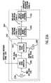
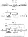
- FIG. 1Ais a block diagram of a universal frequency translation (UFT) module according to an embodiment of the invention.
- UFTuniversal frequency translation
- FIG. 1Bis a more detailed diagram of a universal frequency translation (UFT) module according to an embodiment of the invention.
- UFTuniversal frequency translation
- FIG. 1Cillustrates a UFT module used in a universal frequency down-conversion (UFD) module according to an embodiment of the invention.
- UFDuniversal frequency down-conversion
- FIG. 1Dillustrates a UFT module used in a universal frequency up-conversion (UFU) module according to an embodiment of the invention.
- UFTuniversal frequency up-conversion
- FIG. 2is a block diagram of a universal frequency translation (UFT) module according to an alternative embodiment of the invention.
- UFTuniversal frequency translation
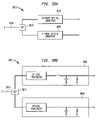
- FIG. 3is a block diagram of a universal frequency up-conversion (UFU) module according to an embodiment of the invention.
- FIG. 4is a more detailed diagram of a universal frequency up-conversion (UFU) module according to an embodiment of the invention.
- FIG. 5is a block diagram of a universal frequency up-conversion (UFU) module according to an alternative embodiment of the invention.
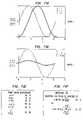
- FIGS. 6A-61illustrate example waveforms used to describe the operation of the UFU module.
- FIG. 7illustrates a UFT module used in a receiver according to an embodiment of the invention.
- FIG. 8illustrates a UFT module used in a transmitter according to an embodiment of the invention.
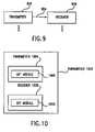
- FIG. 9illustrates an environment comprising a transmitter and a receiver, each of which may be implemented using a UFT module of the invention.
- FIG. 10illustrates a transceiver according to an embodiment of the invention.
- FIG. 11illustrates a transceiver according to an alternative embodiment of the invention.
- FIG. 12illustrates an environment comprising a transmitter and a receiver, each of which may be implemented using enhanced signal reception (ESR) components of the invention.
- ESRenhanced signal reception
- FIG. 13illustrates a UFT module used in a unified down-conversion and filtering (UDF) module according to an embodiment of the invention.
- FIG. 14illustrates an example receiver implemented using a UDF module according to an embodiment of the invention.
- FIGS. 15A-15Fillustrate example applications of the UDF module according to embodiments of the invention.
- FIG. 16illustrates an environment comprising a transmitter and a receiver, each of which may be implemented using enhanced signal reception (ESR) components of the invention, wherein the receiver may be further implemented using one or more UFD modules of the invention.
- ESRenhanced signal reception
- FIG. 17illustrates a unified down-converting and filtering (UDF) module according to an embodiment of the invention.
- FIG. 18is a table of example values at nodes in the UDF module of FIG. 17 .
- FIG. 19is a detailed diagram of an example UDF module according to an embodiment of the invention.
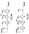
- FIGS. 20A and 20Gare example aliasing modules according to embodiments of the invention.
- FIGS. 20B-20Fare example waveforms used to describe the operation of the aliasing modules of FIGS. 20A and 20G .
- FIG. 21illustrates an enhanced signal reception system according to an embodiment of the invention.
- FIGS. 22A-22Fare example waveforms used to describe the system of FIG. 21 .
- FIG. 23Aillustrates an example transmitter in an enhanced signal reception system according to an embodiment of the invention.
- FIGS. 23B and 23Care example waveforms used to further describe the enhanced signal reception system according to an embodiment of the invention.
- FIG. 23Dillustrates another example transmitter in an enhanced signal reception system according to an embodiment of the invention.
- FIGS. 23E and 23Fare example waveforms used to further describe the enhanced signal reception system according to an embodiment of the invention.
- FIG. 24Aillustrates an example receiver in an enhanced signal reception system according to an embodiment of the invention.
- FIGS. 24B-24Jare example waveforms used to further describe the enhanced signal reception system according to an embodiment of the invention.
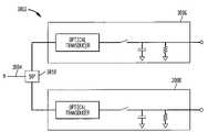
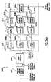
- FIG. 25illustrates a high level block diagram of an optical converter in accordance with the present invention.
- FIG. 26illustrates an example embodiment of the optical converter illustrated in FIG. 25 .
- FIG. 27illustrates an example implementation of an optical transducer illustrated in FIG. 26 .
- FIG. 28illustrates an example implementation of a universal frequency translator illustrated in FIG. 26 .
- FIG. 29illustrates example details of a universal frequency translator illustrated in FIG. 28 .
- FIG. 30illustrates exemplary details of the universal frequency translator illustrated in FIG. 26 .
- FIG. 31illustrates exemplary details of the universal frequency translator illustrated in FIG. 26 .
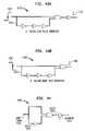
- FIG. 32illustrates an example portion of an optical signal.
- FIG. 33illustrates an example hypothetical charging signal.
- FIG. 34illustrates an example energy transfer signal for controlling the universal frequency translator illustrated in FIG. 28 .
- FIG. 35illustrates an example charging/discharging signal.
- FIG. 36illustrates a hypothetical energy transfer storage signal.
- FIG. 37illustrates an example demodulated electrical information signal generated in accordance with the present invention.
- FIG. 38Aillustrates an example I&Q optical converter, in accordance with the present invention.
- FIG. 38Billustrates an example implementation of the I&Q optical converter illustrated in FIG. 38A .
- FIG. 38Cillustrates an example process flowchart for demodulating an optical signal to a demodulated electrical information signal, in accordance with the present invention.
- FIGS. 39-42illustrate example implementations of a switch module according to embodiments of the invention.
- FIGS. 43A-Billustrate example aperture generators.
- FIGS. 44-45illustrate example aperture generators.
- FIG. 46illustrates an oscillator according to an embodiment of the present invention.
- FIG. 47illustrates an energy transfer system with an optional energy transfer signal module according to an embodiment of the invention.
- FIG. 48illustrates an aliasing module with input and output impedance match according to an embodiment of the invention.
- FIG. 49Aillustrates an example pulse generator
- FIGS. 49B and Cillustrate example waveforms related to the pulse generator of FIG. 49A .
- FIG. 50illustrates an example energy transfer module with a switch module and a reactive storage module according to an embodiment of the invention.
- FIGS. 51A-Billustrate example energy transfer systems according to embodiments of the invention.
- FIG. 52Aillustrates an example energy transfer signal module according to an embodiment of the present invention.
- FIG. 52Billustrates a flowchart of state machine operation according to an embodiment of the present invention.
- FIG. 52Cis an example energy transfer signal module.
- FIG. 53is a schematic diagram of a circuit to down-convert a 915 MHZ signal to a 5 MHZ signal using a 101.1 MHZ clock according to an embodiment of the present invention.
- FIG. 54shows example simulation waveforms for the circuit of FIG. 53 according to embodiments of the present invention.
- FIG. 55is a schematic diagram of a circuit to down-convert a 915 MHZ signal to a 5 MHZ signal using a 101 MHZ clock according to an embodiment of the present invention.
- FIG. 56shows example simulation waveforms for the circuit of FIG. 55 according to embodiments of the present invention.
- FIG. 57is a schematic diagram of a circuit to down-convert a 915 MHZ signal to a 5 MHZ signal using a 101.1 MHZ clock according to an embodiment of the present invention.
- FIG. 58shows example simulation waveforms for the circuit of FIG. 57 according to an embodiment of the present invention.
- FIG. 59shows a schematic of the circuit in FIG. 53 connected to an FSK source that alternates between 913 and 917 MHZ at a baud rate of 500 Kbaud according to an embodiment of the present invention.
- FIG. 60Aillustrates an example energy transfer system according to an embodiment of the invention.
- FIGS. 60B-Cillustrate example timing diagrams for the example system of FIG. 60A .
- FIG. 61illustrates an example bypass network according to an embodiment of the invention.
- FIG. 62illustrates an example bypass network according to an embodiment of the invention.
- FIG. 63illustrates an example embodiment of the invention.
- FIG. 64Aillustrates an example real time aperture control circuit according to an embodiment of the invention.
- FIG. 64Billustrates a timing diagram of an example clock signal for real time aperture control, according to an embodiment of the invention.
- FIG. 64Cillustrates a timing diagram of an example optional enable signal for real time aperture control, according to an embodiment of the invention.
- FIG. 64Dillustrates a timing diagram of an inverted clock signal for real time aperture control, according to an embodiment of the invention.
- FIG. 64Eillustrates a timing diagram of an example delayed clock signal for real time aperture control, according to an embodiment of the invention.
- FIG. 64Fillustrates a timing diagram of an example energy transfer including pulses having apertures that are controlled in real time, according to an embodiment of the invention.
- FIG. 65illustrates an example embodiment of the invention.
- FIG. 66illustrates an example embodiment of the invention.
- FIG. 67illustrates an example embodiment of the invention.
- FIG. 68illustrates an example embodiment of the invention.
- FIG. 69Ais a timing diagram for the example embodiment of FIG. 65 .
- FIG. 69Bis a timing diagram for the example embodiment of FIG. 66 .
- FIG. 70Ais a timing diagram for the example embodiment of FIG. 67 .
- FIG. 70Bis a timing diagram for the example embodiment of FIG. 68 .
- FIG. 71Aillustrates and example embodiment of the invention.
- FIG. 71Billustrates example equations for determining charge transfer, in accordance with the present invention.
- FIG. 71Cillustrates relationships between capacitor charging and aperture, in accordance with an embodiment of the present invention.
- FIG. 71Dillustrates relationships between capacitor charging and aperture, in accordance with an embodiment of the present invention.
- FIG. 71Eillustrates power-charge relationship equations, in accordance with an embodiment of the present invention.
- FIG. 71Fillustrates insertion loss equations, in accordance with an embodiment of the present invention.
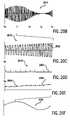
- FIG. 72shows an original FSK waveform and a down-converted waveform.
- the present inventionis directed to methods and systems for demodulating an optical signal to a demodulated electrical information signal.
- An optical converter in accordance with the present inventionmay include one or more receivers, transmitters, and transceivers. According to embodiments of the invention, at least some of these receivers, transmitters, and transceivers are implemented using universal frequency translation (UFT) modules.
- UFTuniversal frequency translation
- the UFT modulesperform frequency translation operations. Embodiments of the present invention incorporating various applications of the UFT module are described below.
- Optical convertersexhibit multiple advantages by using UFT modules. These advantages include, but are not limited to, lower power consumption, longer power source life, fewer parts, lower cost, less tuning, and more effective signal transmission and reception.
- An optical converterin accordance with the present invention, can receive and transmit optical signals across a broad frequency range. The structure and operation of embodiments of the UFT module, and various applications of the same are described in detail in the following sections.
- the present inventionis related to frequency translation, and applications of same.
- Such applicationsinclude, but are not limited to, frequency down-conversion, frequency up-conversion, enhanced signal reception, unified down-conversion and filtering, and combinations and applications of same.
- FIG. 1Aillustrates a universal frequency translation (UFT) module 102 according to embodiments of the invention.
- the UFT moduleis also sometimes called a universal frequency translator, or a universal translator.
- some embodiments of the UFT module 102include three ports (nodes), designated in FIG. 1A as Port 1 , Port 2 , and Port 3 .
- Other UFT embodimentsinclude other than three ports.
- the UFT module 102(perhaps in combination with other components) operates to generate an output signal from an input signal, where the frequency of the output signal differs from the frequency of the input signal.
- the UFT module 102(and perhaps other components) operates to generate the output signal from the input signal by translating the frequency (and perhaps other characteristics) of the input signal to the frequency (and perhaps other characteristics) of the output signal.
- FIG. 1BAn example embodiment of the UFT module 103 is generally illustrated in FIG. 1B .
- the UFT module 103includes a switch 106 controlled by a control signal 108 .
- the switch 106is said to be a controlled switch.
- FIG. 2illustrates an example UFT module 202 .
- the example UFT module 202includes a diode 204 having two ports, designated as Port 1 and Port 2 / 3 . This embodiment does not include a third port, as indicated by the dotted line around the “Port 3 ” label.
- the UFT moduleis a very powerful and flexible device. Its flexibility is illustrated, in part, by the wide range of applications in which it can be used. Its power is illustrated, in part, by the usefulness and performance of such applications.
- a UFT module 115can be used in a universal frequency down-conversion (UFD) module 114 , an example of which is shown in FIG. 1C .
- UFDuniversal frequency down-conversion
- the UFT module 115frequency down-converts an input signal to an output signal.
- a UFT module 117can be used in a universal frequency up-conversion (UFU) module 116 .
- UFT module 117frequency up-converts an input signal to an output signal.
- the UFT moduleis a required component. In other applications, the UFT module is an optional component.
- the present inventionis directed to systems and methods of universal frequency down-conversion, and applications of same.
- FIG. 20Aillustrates an aliasing module 2000 for down-conversion using a universal frequency translation (UFT) module 2002 which down-converts an EM input signal 2004 .
- aliasing module 2000includes a switch 2008 and a capacitor 2010 .
- the electronic alignment of the circuit componentsis flexible. That is, in one implementation, the switch 2008 is in series with input signal 2004 and capacitor 2010 is shunted to ground (although it may be other than ground in configurations such as differential mode). In a second implementation (see FIG. 20G ), the capacitor 2010 is in series with the input signal 2004 and the switch 2008 is shunted to ground (although it may be other than ground in configurations such as differential mode).
- Aliasing module 2000 with UFT module 2002can be easily tailored to down-convert a wide variety of electromagnetic signals using aliasing frequencies that are well below the frequencies of the EM input signal 2004 .
- aliasing module 2000down-converts the input signal 2004 to an intermediate frequency (IF) signal. In another implementation, the aliasing module 2000 down-converts the input signal 2004 to a demodulated baseband signal. In yet another implementation, the input signal 2004 is a frequency modulated (FM) signal, and the aliasing module 2000 down-converts it to a non-FM signal, such as a phase modulated (PM) signal or an amplitude modulated (AM) signal.
- FMfrequency modulated
- AMamplitude modulated
- control signal 2006includes a train of pulses that repeat at an aliasing rate that is equal to, or less than, twice the frequency of the input signal 2004 .
- control signal 2006is referred to herein as an aliasing signal because it is below the Nyquist rate for the frequency of the input signal 2004 .
- the frequency of control signal 2006is much less than the input signal 2004 .
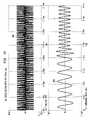
- a train of pulses 2018 as shown in FIG. 20Dcontrols the switch 2008 to alias the input signal 2004 with the control signal 2006 to generate a down-converted output signal 2012 . More specifically, in an embodiment, switch 2008 closes on a first edge of each pulse 2020 of FIG. 20D and opens on a second edge of each pulse. When the switch 2008 is closed, the input signal 2004 is coupled to the capacitor 2010 , and charge is transferred from the input signal to the capacitor 2010 . The charge stored during successive pulses forms down-converted output signal 2012 .
- Exemplary waveformsare shown in FIGS. 20B-20F .
- FIG. 20Billustrates an analog amplitude modulated (AM) carrier signal 2014 that is an example of input signal 2004 .
- AManalog amplitude modulated
- FIG. 20Can analog AM carrier signal portion 2016 illustrates a portion of the analog AM carrier signal 2014 on an expanded time scale.
- the analog AM carrier signal portion 2016illustrates the analog AM carrier signal 2014 from time t 0 time t 1 .
- FIG. 20Dillustrates an exemplary aliasing signal 2018 that is an example of control signal 2006 .
- Aliasing signal 2018is on approximately the same time scale as the analog AM carrier signal portion 2016 .
- the aliasing signal 2018includes a train of pulses 2020 having negligible apertures that tend towards zero (the invention is not limited to this embodiment, as discussed below).
- the pulse aperturemay also be referred to as the pulse width as will be understood by those skilled in the art(s).
- the pulses 2020repeat at an aliasing rate, or pulse repetition rate of aliasing signal 2018 .
- the aliasing rateis determined as described below, and further described in co-pending U.S. patent application entitled “Method and System for Down-converting Electromagnetic Signals,” Ser. No. 09/176,022.
- the train of pulses 2020control signal 2006
- control signal 2006control the switch 2008 to alias the analog AM carrier signal 2016 (i.e., input signal 2004 ) at the aliasing rate of the aliasing signal 2018 .
- the switch 2008closes on a first edge of each pulse and opens on a second edge of each pulse.
- input signal 2004is coupled to the capacitor 2010
- chargeis transferred from the input signal 2004 to the capacitor 2010 .
- the charge transferred during a pulseis referred to herein as an under-sample.
- Exemplary under-samples 2022form down-converted signal portion 2024 ( FIG. 20E ) that corresponds to the analog AM carrier signal portion 2016 ( FIG.
- FIGS. 20B-20Fillustrate down-conversion of AM carrier signal 2014 .
- FIGS. 20B-20FThe waveforms shown in FIGS. 20B-20F are discussed herein for illustrative purposes only, and are not limiting. Additional exemplary time domain and frequency domain drawings, and exemplary methods and systems of the invention relating thereto, are disclosed in co-pending U.S. patent application entitled “Method and System for Down-converting Electromagnetic Signals,” Ser. No. 09/176,022.
- the aliasing rate of control signal 2006determines whether the input signal 2004 is down-converted to an IF signal, down-converted to a demodulated baseband signal, or down-converted from an FM signal to a PM or an AM signal.
- the input signal 2004the aliasing rate of the control signal 2006
- the down-converted output signal 2012the down-converted output signal 2012
- input signal 2004is down-converted to an IF signal. This is because the under-sampling pulses occur at different phases of subsequent cycles of input signal 2004 . As a result, the under-samples form a lower frequency oscillating pattern. If the input signal 2004 includes lower frequency changes, such as amplitude, frequency, phase, etc., or any combination thereof, the charge stored during associated under-samples reflects the lower frequency changes, resulting in similar changes on the down-converted IF signal.
- the frequency of the control signal 2006would be substantially equal to 1.8 GHz, 900 MHZ, 450 MHZ, 300 MHZ, 225 MHZ, etc.
- Exemplary time domain and frequency domain drawingsillustrating down-conversion of analog and digital AM, PM and FM signals to IF signals, and exemplary methods and systems thereof, are disclosed in co-pending U.S. patent application entitled “Method and System for Down-converting Electromagnetic Signals,” Ser. No. 09/176,022.
- the aliasing rate of the control signal 2006is substantially equal to the frequency of the input signal 2004 , or substantially equal to a harmonic or sub-harmonic thereof
- input signal 2004is directly down-converted to a demodulated baseband signal. This is because, without modulation, the under-sampling pulses occur at the same point of subsequent cycles of the input signal 2004 . As a result, the under-samples form a constant output baseband signal. If the input signal 2004 includes lower frequency changes, such as amplitude, frequency, phase, etc., or any combination thereof, the charge stored during associated under-samples reflects the lower frequency changes, resulting in similar changes on the demodulated baseband signal.
- the frequency of the control signal 2006should be substantially equal to 1.8 GHz, 900 MHZ, 450 MHZ, 300 MHZ, 225 MHZ, etc.
- Exemplary time domain and frequency domain drawingsillustrating direct down-conversion of analog and digital AM and PM signals to demodulated baseband signals, and exemplary methods and systems thereof, are disclosed in the co-pending U.S. patent application entitled “Method and System for Down-converting Electromagnetic Signals,” Ser. No. 09/176,022.
- a frequency within the FM bandwidthmust be down-converted to baseband (i.e., zero IF).
- basebandi.e., zero IF
- FSKfrequency shift keying
- PSKphase shift keying
- the mid-point between a lower frequency F 1 and an upper frequency F 2 (that is, [(F 1 +F 2 ) ⁇ 2]) of the FSK signalis down-converted to zero IF.
- F 1frequency shift keying
- PSKphase shift keying
- the aliasing rate of the control signal 2006would be calculated as follows:
- the frequency of the control signal 2006should be substantially equal to 1.8 GHz, 900 MHZ, 450 MHZ, 300 MHZ, 225 MHZ, etc.
- the frequency of the down-converted PSK signalis substantially equal to one half the difference between the lower frequency F 1 and the upper frequency F 2 .
- the frequency of the control signal 2006should be substantially equal to 1.8 GHz, 900 MHZ, 450 MHZ, 300 MHZ, 225 MHZ, etc.
- the frequency of the control signal 2006should be substantially equal to 1.802 GHz, 901 MHZ, 450.5 MHZ, 300.333 MHZ, 225.25 MHZ, etc.
- the frequency of the down-converted AM signalis substantially equal to the difference between the lower frequency F 1 and the upper frequency F 2 (i.e., 1 MHZ).
- the pulses of the control signal 2006have negligible apertures that tend towards zero. This makes the UFT module 2002 a high input impedance device. This configuration is useful for situations where minimal disturbance of the input signal may be desired.
- the pulses of the control signal 2006have non-negligible apertures that tend away from zero.
- Thismakes the UFT module 2002 a lower input impedance device. This allows the lower input impedance of the UFT module 2002 to be substantially matched with a source impedance of the input signal 2004 . This also improves the energy transfer from the input signal 2004 to the down-converted output signal 2012 , and hence the efficiency and signal to noise (s/n) ratio of UFT module 2002 .
- the aliasing module 2000is referred to interchangeably herein as an energy transfer module or a gated transfer module, and the control signal 2006 is referred to as an energy transfer signal.
- Exemplary systems and methods for generating and optimizing the control signal 2006 and for otherwise improving energy transfer and/or signal to noise ratio in an energy transfer moduleare described below.
- FIG. 47illustrates an energy transfer system 4701 that includes an optional energy transfer signal module 4702 , which can perform any of a variety of functions or combinations of functions including, but not limited to, generating the energy transfer signal 4106 .
- the optional energy transfer signal module 4702includes an aperture generator, an example of which is illustrated in FIG. 44 as an aperture generator 4420 .
- the aperture generator 4420generates non-negligible aperture pulses 4326 from an input signal 4324 .
- the input signal 4324can be any type of periodic signal, including, but not limited to, a sinusoid, a square wave, a saw-tooth wave, etc. Systems for generating the input signal 4324 are described below.
- the width or aperture of the pulses 4326is determined by delay through the branch 4322 of the aperture generator 4420 .
- the difficulty in meeting the requirements of the aperture generator 4420decrease.
- the components utilized in the example aperture generator 4420do not require as fast reaction times as those that are required in an under-sampling system operating with the same EM input frequency.
- the example logic and implementation shown in the aperture generator 4420are provided for illustrative purposes only, and are not limiting. The actual logic employed can take many forms.
- the example aperture generator 4420includes an optional inverter 4428 , which is shown for polarity consistency with other examples provided herein.
- FIG. 45An example implementation of the aperture generator 4420 is illustrated in FIG. 45 . Additional examples of aperture generation logic are provided in FIGS. 43A and 43B .
- FIG. 43Aillustrates a rising edge pulse generator 4340 , which generates pulses 4326 on rising edges of the input signal 4324 .
- FIG. 43Billustrates a falling edge pulse generator 4350 , which generates pulses 4326 on falling edges of the input signal 4324 .
- the input signal 4324is generated externally of the energy transfer signal module 4702 , as illustrated in FIG. 47 .
- the input signal 4724is generated internally by the energy transfer signal module 4702 .
- the input signal 4324can be generated by an oscillator, as illustrated in FIG. 46 by an oscillator 4630 .
- the oscillator 4630can be internal to the energy transfer signal module 4702 or external to the energy transfer signal module 4702 .
- the oscillator 4630can be external to the energy transfer system 4701 .
- the output of the oscillator 4630may be any periodic waveform.
- the type of down-conversion performed by the energy transfer system 4701depends upon the aliasing rate of the energy transfer signal 4106 , which is determined by the frequency of the pulses 4326 .
- the frequency of the pulses 4326is determined by the frequency of the input signal 4324 .
- the EM signal 3904is directly down-converted to baseband (e.g. when the EM signal is an AM signal or a PM signal), or converted from FM to a non-FM signal.
- the frequency of the input signal 4324is substantially equal to a harmonic or a sub-harmonic of a difference frequency
- the EM signal 3904is down-converted to an intermediate signal.
- the optional energy transfer signal module 4702can be implemented in hardware, software, firmware, or any combination thereof.
- the down-converted output signal 2012may be smoothed by filtering as desired.
- the energy transfer module 2000has input and output impedances generally defined by (1) the duty cycle of the switch module (i.e., UFT 2002 ), and (2) the impedance of the storage module (e.g., capacitor 2010 ), at the frequencies of interest (e.g. at the EM input, and intermediate/baseband frequencies).
- this aperture width(e.g. the “closed time”) can be decreased.
- the characteristic impedance at the input and the output of the energy transfer moduleincreases.
- the impedance of the energy transfer moduledecreases.
- the energy transfer module's characteristic input impedanceis 300 ohms.
- An impedance matching circuitcan be utilized to efficiently couple an input EM signal that has a source impedance of, for example, 50 ohms, with the energy transfer module's impedance of, for example, 300 ohms. Matching these impedances can be accomplished in various manners, including providing the necessary impedance directly or the use of an impedance match circuit as described below.
- an initial configuration for the input impedance match module 4806can include an inductor 5006 and a capacitor 5008 , configured as shown in FIG. 50 .
- the configuration of the inductor 5006 and the capacitor 5008is a possible configuration when going from a low impedance to a high impedance.
- Inductor 5006 and the capacitor 5008constitute an L match, the calculation of the values which is well known to those skilled in the relevant arts.
- the output characteristic impedancecan be impedance matched to take into consideration the desired output frequencies.
- One of the steps in determining the characteristic output impedance of the energy transfer modulecould be to measure its value. Balancing the very low impedance of the storage module at the input EM frequency, the storage module should have an impedance at the desired output frequencies that is preferably greater than or equal to the load that is intended to be driven (for example, in an embodiment, storage module impedance at a desired 1 MHz output frequency is 2K ohm and the desired load to be driven is 50 ohms).
- An additional benefit of impedance matchingis that filtering of unwanted signals can also be accomplished with the same components.
- the energy transfer module's characteristic output impedanceis 2K ohms.
- An impedance matching circuitcan be utilized to efficiently couple the down-converted signal with an output impedance of, for example, 2K ohms, to a load of, for example, 50 ohms. Matching these impedances can be accomplished in various manners, including providing the necessary load impedance directly or the use of an impedance match circuit as described below.
- a capacitor 5014 and an inductor 5016can be configured as shown in FIG. 50 .
- the capacitor 5014 and the inductor 5016constitute an L match, the calculation of the component values being well known to those skilled in the relevant arts.
- the configuration of the input impedance match module 4806 and the output impedance match module 4808are considered to be initial starting points for impedance matching, in accordance with the present invention. In some situations, the initial designs may be suitable without further optimization. In other situations, the initial designs can be optimized in accordance with other various design criteria and considerations.
- Resonant tank and other resonant structurescan be used to further optimize the energy transfer characteristics of the invention.
- resonant structuresresonant about the input frequency
- Resonant tank and other resonant structurescan include, but are not limited to, surface acoustic wave (SAW) filters, dielectric resonators, diplexers, capacitors, inductors, etc.
- SAWsurface acoustic wave
- FIG. 60AAn example embodiment is shown in FIG. 60A .
- Two additional embodimentsare shown in FIG. 55 and FIG. 63 .
- Alternate implementationswill be apparent to persons skilled in the relevant art(s) based on the teachings contained herein. Alternate implementations fall within the scope and spirit of the present invention. These implementations take advantage of properties of series and parallel (tank) resonant circuits.
- FIG. 60Aillustrates parallel tank circuits in a differential implementation.
- a first parallel resonant or tank circuitconsists of a capacitor 6038 and an inductor 6020 (tank 1 ).
- a second tank circuitconsists of a capacitor 6034 and an inductor 6036 (tank 2 ).
- the first and second tank circuitsresonate at approximately 920 MHz. At and near resonance, the impedance of these circuits is relatively high. Therefore, in the circuit configuration shown in FIG. 60A , both tank circuits appear as relatively high impedance to the input frequency of 950 MHz, while simultaneously appearing as relatively low impedance to frequencies in the desired output range of 50 MHz.
- An energy transfer signal 6042controls a switch 6014 .
- the energy transfer signal 6042controls the switch 6014 to open and close, high frequency signal components are not allowed to pass through tank 1 or tank 2 .
- the lower signal components (50 Mhz in this embodiment) generated by the systemare allowed to pass through tank 1 and tank 2 with little attenuation.
- the effect of tank 1 and tank 2is to further separate the input and output signals from the same node thereby producing a more stable input and output impedance.
- Capacitors 6018 and 6040act to store the 50 MHz output signal energy between energy transfer pulses.
- an inductor 6010in series with a storage capacitor 6012 as shown.
- the series resonant frequency of this circuit arrangementis approximately 1 GHz.
- This circuitincreases the energy transfer characteristic of the system.
- the ratio of the impedance of inductor 6010 and the impedance of the storage capacitor 6012is preferably kept relatively small so that the majority of the energy available will be transferred to storage capacitor 6012 during operation.
- Exemplary output signals A and Bare illustrated in FIGS. 60B and 60C , respectively.
- circuit components 6004 and 6006form an input impedance match.
- Circuit components 6032 and 6030form an output impedance match into a 50 ohm resistor 6028 .
- Circuit components 6022 and 6024form a second output impedance match into a 50 ohm resistor 6026 .
- Capacitors 6008 and 6012act as storage capacitors for the embodiment.
- Voltage source 6046 and resistor 6002generate a 950 MHz signal with a 50 ohm output impedance, which are used as the input to the circuit.
- Circuit element 6016includes a 150 MHz oscillator and a pulse generator, which are used to generate the energy transfer signal 6042 .
- FIG. 55illustrates a shunt tank circuit 5510 in a single-ended to-single-ended system 5512 .
- FIG. 63illustrates a shunt tank circuit 6310 in a system 6312 .
- the tank circuits 5510 and 6310lower driving source impedance, which improves transient response.
- the tank circuits 5510 and 6310are able store the energy from the input signal and provide a low driving source impedance to transfer that energy throughout the aperture of the closed switch.
- the transient nature of the switch aperturecan be viewed as having a response that, in addition to including the input frequency, has large component frequencies above the input frequency, (i.e. higher frequencies than the input frequency are also able to effectively pass through the aperture).
- Resonant circuits or structuresfor example resonant tanks 5510 or 6310 , can take advantage of this by being able to transfer energy throughout the switch's transient frequency response (i.e. the capacitor in the resonant tank appears as a low driving source impedance during the transient period of the aperture).
- tank and resonant structures described aboveare for illustrative purposes and are not limiting. Alternate configurations can be utilized. The various resonant tanks and structures discussed can be combined or utilized independently as is now apparent.
- FIG. 71Aillustrates a circuit 7102 , including a switch S and a capacitor 7106 having a capacitance C.
- the switch Sis controlled by a control signal 7108 , which includes pulses 7110 having apertures T.
- Equation 2illustrates that the charge q on a capacitor having a capacitance C, such as the capacitor 7106 , is proportional to the voltage V across the capacitor, where:
- Equation 2can be rewritten as Equation 4.
- Equation 5The change in charge ⁇ q over time t is illustrated as in Equation 5 as ⁇ q(t), which can be rewritten as Equation 6.
- Equation 7Using the sum-to-product trigonometric identity of Equation 7, Equation 6 can be rewritten as Equation 8, which can be rewritten as Equation 9.
- Equation 3is a function of the aperture T only.
- ⁇ q(t)is at a maximum when T is equal to an odd multiple of ⁇ (i.e., ⁇ , 3 ⁇ , 5 ⁇ , . . . ). Therefore, the capacitor 7106 experiences the greatest change in charge when the aperture T has a value of ⁇ or a time interval representative of 180 degrees of the input sinusoid. Conversely, when T is equal to 2 ⁇ , 4 ⁇ , 6 ⁇ , . . . , minimal charge is transferred.
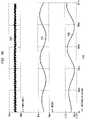
- Equations 10, 11, and 12solve for q(t) by integrating Equation 2, allowing the charge on the capacitor 7106 with respect to time to be graphed on the same axis as the input sinusoid sin(t), as illustrated in the graph of FIG. 71C .
- the aperture Tdecreases in value or tends toward an impulse, the phase between the charge on the capacitor C or q(t) and sin(t) tend toward zero.
- FIG. 71Dwhich indicates that the maximum impulse charge transfer occurs near the input voltage maxima. As this graph indicates, considerably less charge is transferred as the value of T decreases.
- Insertion lossConcepts of insertion loss are illustrated in FIG. 71F .
- the noise figure of a lossy passive deviceis numerically equal to the device insertion loss.
- the noise figure for any devicecannot be less that its insertion loss.
- Insertion losscan be expressed by Equation 19 or 20.
- the energy transfer signal(i.e., control signal 2006 in FIG. 20A ), is used to vary the input impedance seen by the EM Signal 2004 and to vary the output impedance driving a load.
- control signal 2006 in FIG. 20Ais used to vary the input impedance seen by the EM Signal 2004 and to vary the output impedance driving a load.
- An example of this embodimentis described below using a gated transfer module 5101 shown in FIG. 51A . The method described below is not limited to the gated transfer module 5101 .
- the impedance looking into circuit 5102is substantially the impedance of a storage module, illustrated here as a storage capacitance 5108 , in parallel with the impedance of a load 5112 .
- the switch 5106is open, the impedance at point 5114 approaches infinity. It follows that the average impedance at point 5114 can be varied from the impedance of the storage module illustrated in parallel with the load 5112 , to the highest obtainable impedance when switch 5106 is open, by varying the ratio of the time that switch 5106 is open to the time switch 5106 is closed.
- the switch 5106is controlled by an energy transfer signal 5110 .
- the impedance at point 5114can be varied by controlling the aperture width of the energy transfer signal in conjunction with the aliasing rate.
- FIG. 49AAn example method of altering the energy transfer signal 5106 of FIG. 51A is now described with reference to FIG. 49A , where a circuit 4902 receives an input oscillating signal 4906 and outputs a pulse train shown as doubler output signal 4904 .
- the circuit 4902can be used to generate the energy transfer signal 5106 .
- Example waveforms of 4904are shown on FIG. 49C .
- the width of the pulses in the doubler output signal 4904can be varied. Increasing the delay of the signal propagated by inverter 4908 , increases the width of the pulses.
- the signal propagated by inverter 4908can be delayed by introducing a R/C low pass network in the output of inverter 4908 .
- Other means of altering the delay of the signal propagated by inverter 4908will be well known to those skilled in the art.
- the aperture width/durationis adjusted in real time.
- a clock signal 6414( FIG. 64B ) is utilized to generate an energy transfer signal 6416 ( FIG. 64F ), which includes energy transfer pluses 6418 , having variable apertures 6420 .
- the clock signal 6414is inverted as illustrated by inverted clock signal 6422 ( FIG. 64D ).
- the clock signal 6414is also delayed, as illustrated by delayed clock signal 6424 ( FIG. 64E ).
- the inverted clock signal 6414 and the delayed clock signal 6424are then ANDed together, generating an energy transfer signal 6416 , which is active—energy transfer pulses 6418 —when the delayed clock signal 6424 and the inverted clock signal 6422 are both active.
- the amount of delay imparted to the delayed clock signal 6424substantially determines the width or duration of the apertures 6420 . By varying the delay in real time, the apertures are adjusted in real time.
- the inverted clock signal 6422is delayed relative to the original clock signal 6414 , and then ANDed with the original clock signal 6414 .
- the original clock signal 6414is delayed then inverted, and the result ANDed with the original clock signal 6414 .
- FIG. 64Aillustrates an exemplary real time aperture control system 6402 that can be utilized to adjust apertures in real time.
- the example real time aperture control system 6402includes an RC circuit 6404 , which includes a voltage variable capacitor 6412 and a resistor 6426 .
- the real time aperture control system 6402also includes an inverter 6406 and an AND gate 6408 .
- the AND gate 6408optionally includes an enable input 6410 for enabling/disabling the AND gate 6408 .
- the RC circuit 6404.
- the real time aperture control system 6402optionally includes an amplifier 6428 .
- the real time control system 6402receives the input clock signal 6414 , which is provided to both the inverter 6406 and to the RC circuit 6404 .
- the inverter 6406outputs the inverted clock signal 6422 and presents it to the AND gate 6408 .
- the RC circuit 6404delays the clock signal 6414 and outputs the delayed clock signal 6424 .
- the delayis determined primarily by the capacitance of the voltage variable capacitor 6412 . Generally, as the capacitance decreases, the delay decreases.
- the delayed clock signal 6424is optionally amplified by the optional amplifier 6428 , before being presented to the AND gate 6408 .
- Amplificationis desired, for example, where the RC constant of the RC circuit 6404 attenuates the signal below the threshold of the AND gate 6408 .
- the AND gate 6408ANDs the delayed clock signal 6424 , the inverted clock signal 6422 , and the optional Enable signal 6410 , to generate the energy transfer signal 6416 .
- the apertures 6420are adjusted in real time by varying the voltage to the voltage variable capacitor 6412 .
- the apertures 6420are controlled to optimize power transfer.
- the apertures 6420are controlled to maximize power transfer.
- the apertures 6420are controlled for variable gain control (e.g. automatic gain control—AGC).
- AGCautomatic gain control
- power transferis reduced by reducing the apertures 6420 .
- a bypass networkis added to improve the efficiency of the energy transfer module.
- Such a bypass networkcan be viewed as a means of synthetic aperture widening.
- Components for a bypass networkare selected so that the bypass network appears substantially lower impedance to transients of the switch module (i.e., frequencies greater than the received EM signal) and appears as a moderate to high impedance to the input EM signal (e.g., greater that 100 Ohms at the RF frequency).
- the time that the input signal is now connected to the opposite side of the switch moduleis lengthened due to the shaping caused by this network, which in simple realizations may be a capacitor or series resonant inductor-capacitor.
- a network that is series resonant above the input frequencywould be a typical implementation.
- This shapingimproves the conversion efficiency of an input signal that would otherwise, if one considered the aperture of the energy transfer signal only, be relatively low in frequency to be optimal.
- bypass network 6102(shown in this instance as capacitor 6112 ), is shown bypassing switch module 6104 .
- the bypass networkincreases the efficiency of the energy transfer module when, for example, less than optimal aperture widths were chosen for a given input frequency on the energy transfer signal 6106 .
- the bypass network 6102could be of different configurations than shown in FIG. 61 . Such an alternate is illustrated in FIG. 57 .
- FIG. 62illustrates another example bypass network 6202 , including a capacitor 6204 .
- FIG. 67also had three values adjusted in the surrounding circuit to compensate for the impedance changes introduced by the bypass network and narrowed aperture.
- FIG. 68verifies that those changes added to the circuit, but without the bypass network, did not themselves bring about the increased efficiency demonstrated by the embodiment in FIG. 67 with the bypass network.
- FIG. 70Bshows the result of using the circuit in FIG. 68 in which only 1.88 Vpp was able to be applied to a 50 ohm load.
- FIG. 47shows an embodiment of a system 4701 which uses down-converted Signal 4708 B as feedback 4706 to control various characteristics of the energy transfer module 4704 to modify the down-converted signal 4708 B.
- the amplitude of the down-converted signal 4708 Bvaries as a function of the frequency and phase differences between the EM signal 3904 and the energy transfer signal 4106 .
- the down-converted signal 4708 Bis used as the feedback 4706 to control the frequency and phase relationship between the EM signal 3904 and the energy transfer signal 4106 .
- Thiscan be accomplished using the example logic in FIG. 52A .
- the example circuit in FIG. 52Acan be included in the energy transfer signal module 4702 .
- Alternate implementationswill be apparent to persons skilled in the relevant art(s) based on the teachings contained herein. Alternate implementations fall within the scope and spirit of the present invention. In this embodiment a state-machine is used as an example.
- a state machine 5204reads an analog to digital converter, A/D 5202 , and controls a digital to analog converter, DAC 5206 .
- the state machine 5204includes 2 memory locations, Previous and Current, to store and recall the results of reading A/D 5202 .
- the state machine 5204utilizes at least one memory flag.
- the DAC 5206controls an input to a voltage controlled oscillator, VCO 5208 .
- VCO 5208controls a frequency input of a pulse generator 5210 , which, in an embodiment, is substantially similar to the pulse generator shown in FIG. 44 .
- the pulse generator 5210generates energy transfer signal 4106 .
- the state machine 5204operates in accordance with a state machine flowchart 5219 in FIG. 52B .
- the result of this operationis to modify the frequency and phase relationship between the energy transfer signal 4106 and the EM signal 3904 , to substantially maintain the amplitude of the down-converted signal 4708 B at an optimum level.
- the amplitude of the down-converted signal 4708 Bcan be made to vary with the amplitude of the energy transfer signal 4106 .
- the switch module 6502is a FET as shown in FIG. 38
- the gate 3918receives the energy transfer signal 4106
- the amplitude of the energy transfer signal 4106can determine the “on” resistance of the FET, which affects the amplitude of the down-converted signal 4708 B.
- the energy transfer signal module 4702as shown in FIG. 52C , can be an analog circuit that enables an automatic gain control function. Alternate implementations will be apparent to persons skilled in the relevant art(s) based on the teachings contained herein. Alternate implementations fall within the scope and spirit of the present invention.
- Example implementationsare described below for illustrative purposes. The invention is not limited to these examples.
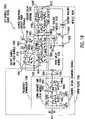
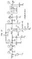
- FIG. 53is a schematic diagram of an exemplary circuit to down convert a 915 MHZ signal to a 5 MHZ signal using a 101.1 MHZ clock.
- FIG. 54shows example simulation waveforms for the circuit of FIG. 53 .
- Waveform 5302is the input to the circuit showing the distortions caused by the switch closure.
- Waveform 5304is the unfiltered output at the storage unit.
- Waveform 5306is the impedance matched output of the down-converter on a different time scale.
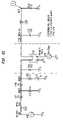
- FIG. 55is a schematic diagram of an exemplary circuit to down-convert a 915 MHZ signal to a 5 MHZ signal using a 101.1 MHZ clock.
- the circuithas additional tank circuitry to improve conversion efficiency.
- FIG. 56shows example simulation waveforms for the circuit of FIG. 55 .
- Waveform 5502is the input to the circuit showing the distortions caused by the switch closure.
- Waveform 5504is the unfiltered output at the storage unit.
- Waveform 5506is the output of the down-converter after the impedance match circuit.
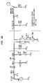
- FIG. 57is a schematic diagram of an exemplary circuit to down-convert a 915 MHZ signal to a 5 MHZ signal using a 101.1 MHZ clock.
- the circuithas switch bypass circuitry to improve conversion efficiency.
- FIG. 58shows example simulation waveforms for the circuit of FIG. 57 .
- Waveform 5702is the input to the circuit showing the distortions caused by the switch closure.
- Waveform 5704is the unfiltered output at the storage unit.
- Waveform 5706is the output of the down-converter after the impedance match circuit.
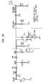
- FIG. 59shows a schematic of the example circuit in FIG. 53 connected to an FSK source that alternates between 913 and 917 MHZ, at a baud rate of 500 Kbaud.
- FIG. 72shows the original FSK waveform 5902 and the down-converted waveform 5904 at the output of the load impedance match circuit.
- the present inventionis directed to systems and methods of frequency up-conversion, and applications of same.
- FIG. 3An example frequency up-conversion system 300 is illustrated in FIG. 3 .
- the frequency up-conversion system 300is now described.
- An input signal 302(designated as “Control Signal” in FIG. 3 ) is accepted by a switch module 304 .
- the input signal 302is a FM input signal 606 , an example of which is shown in FIG. 6C .
- FM input signal 606may have been generated by modulating information signal 602 onto oscillating signal 604 ( FIGS. 6A and 6B ). It should be understood that the invention is not limited to this embodiment.
- the information signal 602can be analog, digital, or any combination thereof, and any modulation scheme can be used.
- the output of switch module 304is a harmonically rich signal 306 , shown for example in FIG. 6D as a harmonically rich signal 608 .
- the harmonically rich signal 608has a continuous and periodic waveform.
- FIG. 6Eis an expanded view of two sections of harmonically rich signal 608 , section 610 and section 612 .
- the harmonically rich signal 608may be a rectangular wave, such as a square wave or a pulse (although, the invention is not limited to this embodiment).
- rectangular waveformis used to refer to waveforms that are substantially rectangular.
- square waverefers to those waveforms that are substantially square and it is not the intent of the present invention that a perfect square wave be generated or needed.
- Harmonically rich signal 608is comprised of a plurality of sinusoidal waves whose frequencies are integer multiples of the fundamental frequency of the waveform of the harmonically rich signal 608 . These sinusoidal waves are referred to as the harmonics of the underlying waveform, and the fundamental frequency is referred to as the first harmonic.
- FIG. 6F and FIG. 6Gshow separately the sinusoidal components making up the first, third, and fifth harmonics of section 610 and section 612 . (Note that in theory there may be an infinite number of harmonics; in this example, because harmonically rich signal 608 is shown as a square wave, there are only odd harmonics). Three harmonics are shown simultaneously (but not summed) in FIG. 6H .
- the relative amplitudes of the harmonicsare generally a function of the relative widths of the pulses of harmonically rich signal 306 and the period of the fundamental frequency, and can be determined by doing a Fourier analysis of harmonically rich signal 306 .
- the input signal 606may be shaped to ensure that the amplitude of the desired harmonic is sufficient for its intended use (e.g., transmission).
- a filter 308filters out any undesired frequencies (harmonics), and outputs an electromagnetic (EM) signal at the desired harmonic frequency or frequencies as an output signal 310 , shown for example as a filtered output signal 614 in FIG. 61 .
- EMelectromagnetic
- FIG. 4illustrates an example universal frequency up-conversion (UFU) module 401 .
- the UFU module 401includes an example switch module 304 , which comprises a bias signal 402 , a resistor or impedance 404 , a universal frequency translator (UFT) 450 , and a ground 408 .
- the UFT 450includes a switch 406 .
- the input signal 302(designated as “Control Signal” in FIG. 4 ) controls the switch 406 in the UFT 450 , and causes it to close and open. Harmonically rich signal 306 is generated at a node 405 located between the resistor or impedance 404 and the switch 406 .
- an example filter 308is comprised of a capacitor 410 and an inductor 412 shunted to a ground 414 .
- the filteris designed to filter out the undesired harmonics of harmonically rich signal 306 .
- the inventionis not limited to the UFU embodiment shown in FIG. 4 .
- an unshaped input signal 501is routed to a pulse shaping module 502 .
- the pulse shaping module 502modifies the unshaped input signal 501 to generate a (modified) input signal 302 (designated as the “Control Signal” in FIG. 5 ).
- the input signal 302is routed to the switch module 304 , which operates in the manner described above.
- the filter 308 of FIG. 5operates in the manner described above.
- the purpose of the pulse shaping module 502is to define the pulse width of the input signal 302 .
- the input signal 302controls the opening and closing of the switch 406 in switch module 304 .
- the pulse width of the input signal 302establishes the pulse width of the harmonically rich signal 306 .
- the relative amplitudes of the harmonics of the harmonically rich signal 306are a function of at least the pulse width of the harmonically rich signal 306 .
- the pulse width of the input signal 302contributes to setting the relative amplitudes of the harmonics of harmonically rich signal 306 .
- the present inventionis directed to systems and methods of enhanced signal reception (ESR), and applications of same.
- ESRenhanced signal reception
- transmitter 2104accepts a modulating baseband signal 2102 and generates (transmitted) redundant spectrums 2106 a - n , which are sent over communications medium 2108 .
- Receiver 2112recovers a demodulated baseband signal 2114 from (received) redundant spectrums 2110 a - n .
- Demodulated baseband signal 2114is representative of the modulating baseband signal 2102 , where the level of similarity between the modulating baseband signal 2114 and the modulating baseband signal 2102 is application dependent.
- Modulating baseband signal 2102is preferably any information signal desired for transmission and/or reception.
- An example modulating baseband signal 2202is illustrated in FIG. 22A , and has an associated modulating baseband spectrum 2204 and image spectrum 2203 that are illustrated in FIG. 22B .
- Modulating baseband signal 2202is illustrated as an analog signal in FIG. 22 a , but could also be a digital signal, or combination thereof.
- Modulating baseband signal 2202could be a voltage (or current) characterization of any number of real world occurrences, including for example and without limitation, the voltage (or current) representation for a voice signal.
- Each transmitted redundant spectrum 2106 a - ncontains the necessary information to substantially reconstruct the modulating baseband signal 2102 .
- each redundant spectrum 2106 a - ncontains the necessary amplitude, phase, and frequency information to reconstruct the modulating baseband signal 2102 .
- FIG. 22Cillustrates example transmitted redundant spectrums 2206 b - d .
- Transmitted redundant spectrums 2206 b - dare illustrated to contain three redundant spectrums for illustration purposes only. Any number of redundant spectrums could be generated and transmitted as will be explained in following discussions.
- Transmitted redundant spectrums 2206 b - dare centered at f 1 , with a frequency spacing f 2 between adjacent spectrums. Frequencies f 1 and f 2 are dynamically adjustable in real-time as will be shown below.
- FIG. 22Dillustrates an alternate embodiment, where redundant spectrums 2208 c,d are centered on unmodulated oscillating signal 2209 at f 1 (Hz). Oscillating signal 2209 may be suppressed if desired using, for example, phasing techniques or filtering techniques.
- Transmitted redundant spectrumsare preferably above baseband frequencies as is represented by break 2205 in the frequency axis of FIGS. 22C and 22D .
- Received redundant spectrums 2110 a - nare substantially similar to transmitted redundant spectrums 2106 a - n , except for the changes introduced by the communications medium 2108 . Such changes can include but are not limited to signal attenuation, and signal interference.
- FIG. 22Eillustrates example received redundant spectrums 2210 b - d . Received redundant spectrums 2210 b - d are substantially similar to transmitted redundant spectrums 2206 b - d , except that redundant spectrum 2210 c includes an undesired jamming signal spectrum 2211 in order to illustrate some advantages of the present invention.
- Jamming signal spectrum 2211is a frequency spectrum associated with a jamming signal.
- a “jamming signal”refers to any unwanted signal, regardless of origin, that may interfere with the proper reception and reconstruction of an intended signal.
- the jamming signalis not limited to tones as depicted by spectrum 2211 , and can have any spectral shape, as will be understood by those skilled in the art(s).
- demodulated baseband signal 2114is extracted from one or more of received redundant spectrums 2210 b - d .
- FIG. 22Fillustrates example demodulated baseband signal 2212 that is, in this example, substantially similar to modulating baseband signal 2202 ( FIG. 22A ); where in practice, the degree of similarity is application dependent.
- the recovery of modulating baseband signal 2202can be accomplished by receiver 2112 in spite of the fact that high strength jamming signal(s) (e.g. jamming signal spectrum 2211 ) exist on the communications medium.
- the intended baseband signalcan be recovered because multiple redundant spectrums are transmitted, where each redundant spectrum carries the necessary information to reconstruct the baseband signal.
- the redundant spectrumsare isolated from each other so that the baseband signal can be recovered even if one or more of the redundant spectrums are corrupted by a jamming signal.
- FIG. 23Aillustrates transmitter 2301 , which is one embodiment of transmitter 2104 that generates redundant spectrums configured similar to redundant spectrums 2206 b - d .
- Transmitter 2301includes generator 2303 , optional spectrum processing module 2304 , and optional medium interface module 2320 .
- Generator 2303includes: first oscillator 2302 , second oscillator 2309 , first stage modulator 2306 , and second stage modulator 2310 .
- Transmitter 2301operates as follows.
- First oscillator 2302 and second oscillator 2309generate a first oscillating signal 2305 and second oscillating signal 2312 , respectively.
- First stage modulator 2306modulates first oscillating signal 2305 with modulating baseband signal 2202 , resulting in modulated signal 2308 .
- First stage modulator 2306may implement any type of modulation including but not limited to: amplitude modulation, frequency modulation, phase modulation, combinations thereof, or any other type of modulation.
- Second stage modulator 2310modulates modulated signal 2308 with second oscillating signal 2312 , resulting in multiple redundant spectrums 2206 a - n shown in FIG. 23B .
- Second stage modulator 2310is preferably a phase modulator, or a frequency modulator, although other types of modulation may be implemented including but not limited to amplitude modulation.
- Each redundant spectrum 2206 a - ncontains the necessary amplitude, phase, and frequency information to substantially reconstruct the modulating baseband signal 2202 .
- Redundant spectrums 2206 a - nare substantially centered around f 1 , which is the characteristic frequency of first oscillating signal 2305 . Also, each redundant spectrum 2206 a - n (except for 2206 c ) is offset from f 1 by approximately a multiple of f 2 (Hz), where f 2 is the frequency of the second oscillating signal 2312 . Thus, each redundant spectrum 2206 a - n is offset from an adjacent redundant spectrum by f 2 (Hz). This allows the spacing between adjacent redundant spectrums to be adjusted (or tuned) by changing f 2 that is associated with second oscillator 2309 . Adjusting the spacing between adjacent redundant spectrums allows for dynamic real-time tuning of the bandwidth occupied by redundant spectrums 2206 a - n.
- the number of redundant spectrums 2206 a - n generated by transmitter 2301is arbitrary and may be unlimited as indicated by the “a-n” designation for redundant spectrums 2206 a - n .
- a typical communications mediumwill have a physical and/or administrative limitations (i.e. FCC regulations) that restrict the number of redundant spectrums that can be practically transmitted over the communications medium.
- FCC regulationsFCC regulations
- the transmitter 2301will include an optional spectrum processing module 2304 to process the redundant spectrums 2206 a - n prior to transmission over communications medium 2108 .
- spectrum processing module 2304includes a filter with a passband 2207 ( FIG. 23C ) to select redundant spectrums 2206 b - d for transmission. This will substantially limit the frequency bandwidth occupied by the redundant spectrums to the passband 2207 .
- spectrum processing module 2304also up converts redundant spectrums and/or amplifies redundant spectrums prior to transmission over the communications medium 2108 .
- medium interface module 2320transmits redundant spectrums over the communications medium 2108 .
- communications medium 2108is an over-the-air link and medium interface module 2320 is an antenna. Other embodiments for communications medium 2108 and medium interface module 2320 will be understood based on the teachings contained herein.
- FIG. 23Dillustrates transmitter 2321 , which is one embodiment of transmitter 2104 that generates redundant spectrums configured similar to redundant spectrums 2208 c - d and unmodulated spectrum 2209 .
- Transmitter 2321includes generator 2311 , spectrum processing module 2304 , and (optional) medium interface module 2320 .
- Generator 2311includes: first oscillator 2302 , second oscillator 2309 , first stage modulator 2306 , and second stage modulator 2310 .
- Transmitter 2321operates as follows.
- First stage modulator 2306modulates second oscillating signal 2312 with modulating baseband signal 2202 , resulting in modulated signal 2322 .
- first stage modulator 2306can effect any type of modulation including but not limited to: amplitude modulation frequency modulation, combinations thereof, or any other type of modulation.
- Second stage modulator 2310modulates first oscillating signal 2304 with modulated signal 2322 , resulting in redundant spectrums 2208 a - n , as shown in FIG. 23E .
- Second stage modulator 2310is preferably a phase or frequency modulator, although other modulators could used including but not limited to an amplitude modulator.
- Redundant spectrums 2208 a - nare centered on unmodulated spectrum 2209 (at f 1 Hz), and adjacent spectrums are separated by f 2 Hz.
- the number of redundant spectrums 2208 a - n generated by generator 2311is arbitrary and unlimited, similar to spectrums 2206 a - n discussed above. Therefore, optional spectrum processing module 2304 may also include a filter with passband 2325 to select, for example, spectrums 2208 c,d for transmission over communications medium 2108 .
- optional spectrum processing module 2304may also include a filter (such as a bandstop filter) to attenuate unmodulated spectrum 2209 . Alternatively, unmodulated spectrum 2209 may be attenuated by using phasing techniques during redundant spectrum generation.
- (optional) medium interface module 2320transmits redundant spectrums 2208 c,d over communications medium 2108 .
- FIG. 24Aillustrates receiver 2430 , which is one embodiment of receiver 2112 .
- Receiver 2430includes optional medium interface module 2402 , down-converter 2404 , spectrum isolation module 2408 , and data extraction module 2414 .
- Spectrum isolation module 2408includes filters 2410 a - c .
- Data extraction module 2414includes demodulators 2416 a - c , error check modules 2420 a - c , and arbitration module 2424 .
- Receiver 2430will be discussed in relation to the signal diagrams in FIGS. 24B-24J .
- optional medium interface module 2402receives redundant spectrums 2210 b - d ( FIG. 22E , and FIG. 24B ).
- Each redundant spectrum 2210 b - dincludes the necessary amplitude, phase, and frequency information to substantially reconstruct the modulating baseband signal used to generated the redundant spectrums.
- spectrum 2210 calso contains jamming signal 2211 , which may interfere with the recovery of a baseband signal from spectrum 2210 c .
- Down-converter 2404down-converts received redundant spectrums 2210 b - d to lower intermediate frequencies, resulting in redundant spectrums 2406 a - c ( FIG. 24C ).
- Jamming signal 2211is also down-converted to jamming signal 2407 , as it is contained within redundant spectrum 2406 b .
- Spectrum isolation module 2408includes filters 2410 a - c that isolate redundant spectrums 2406 a - c from each other ( FIGS. 24D-24F , respectively).
- Demodulators 2416 a - cindependently demodulate spectrums 2406 a - c , resulting in demodulated baseband signals 2418 a - c , respectively ( FIGS. 24G-24D ).
- Error check modules 2420 a - canalyze demodulate baseband signal 2418 a - c to detect any errors.
- each error check module 2420 a - csets an error flag 2422 a - c whenever an error is detected in a demodulated baseband signal.
- Arbitration module 2424accepts the demodulated baseband signals and associated error flags, and selects a substantially error-free demodulated baseband signal ( FIG. 24J ).
- the substantially error-free demodulated baseband signalwill be substantially similar to the modulating baseband signal used to generate the received redundant spectrums, where the degree of similarity is application dependent.
- arbitration module 2424will select either demodulated baseband signal 2418 a or 2418 c , because error check module 2420 b will set the error flag 2422 b that is associated with demodulated baseband signal 2418 b.
- the error detection schemes implemented by the error detection modulesinclude but are not limited to: cyclic redundancy check (CRC) and parity check for digital signals, and various error detections schemes for analog signal.
- CRCcyclic redundancy check
- parity checkfor digital signals
- various error detections schemes for analog signalinclude but are not limited to: cyclic redundancy check (CRC) and parity check for digital signals, and various error detections schemes for analog signal.
- the present inventionis directed to systems and methods of unified down-conversion and filtering (UDF), and applications of same.
- UDFunified down-conversion and filtering
- the present inventionincludes a unified down-converting and filtering (UDF) module that performs frequency selectivity and frequency translation in a unified (i.e., integrated) manner.
- UDFdown-converting and filtering
- the inventionachieves high frequency selectivity prior to frequency translation (the invention is not limited to this embodiment).
- the inventionachieves high frequency selectivity at substantially any frequency, including but not limited to RF (radio frequency) and greater frequencies. It should be understood that the invention is not limited to this example of RF and greater frequencies.
- the inventionis intended, adapted, and capable of working with lower than radio frequencies.
- FIG. 17is a conceptual block diagram of a UDF module 1702 according to an embodiment of the present invention.
- the UDF module 1702performs at least frequency translation and frequency selectivity.
- the effect achieved by the UDF module 1702is to perform the frequency selectivity operation prior to the performance of the frequency translation operation.
- the UDF module 1702effectively performs input filtering.
- such input filteringinvolves a relatively narrow bandwidth.
- such input filteringmay represent channel select filtering, where the filter bandwidth may be, for example, 50 KHz to 150 KHz. It should be understood, however, that the invention is not limited to these frequencies. The invention is intended, adapted, and capable of achieving filter bandwidths of less than and greater than these values.
- input signals 1704 received by the UDF module 1702are at radio frequencies.
- the UDF module 1702effectively operates to input filter these RF input signals 1704 .
- the UDF module 1702effectively performs input, channel select filtering of the RF input signal 1704 . Accordingly, the invention achieves high selectivity at high frequencies.
- the UDF module 1702effectively performs various types of filtering, including but not limited to bandpass filtering, low pass filtering, high pass filtering, notch filtering, all pass filtering, band stop filtering, etc., and combinations thereof.
- the UDF module 1702includes a frequency translator 1708 .
- the frequency translator 1708conceptually represents that portion of the UDF module 1702 that performs frequency translation (down conversion).
- the UDF module 1702also conceptually includes an apparent input filter 1706 (also sometimes called an input filtering emulator).
- the apparent input filter 1706represents that portion of the UDF module 1702 that performs input filtering.
- the input filtering operation performed by the UDF module 1702is integrated with the frequency translation operation.
- the input filtering operationcan be viewed as being performed concurrently with the frequency translation operation. This is a reason why the input filter 1706 is herein referred to as an “apparent” input filter 1706 .
- the UDF module 1702 of the present inventionincludes a number of advantages. For example, high selectivity at high frequencies is realizable using the UDF module 1702 . This feature of the invention is evident by the high Q factors that are attainable.
- the UDF module 1702can be designed with a filter center frequency f C on the order of 900 MHZ, and a filter bandwidth on the order of 50 KHz. This represents a Q of 18 , 000 (Q is equal to the center frequency divided by the bandwidth).
- the inventionis not limited to filters with high Q factors.
- the filters contemplated by the present inventionmay have lesser or greater Qs, depending on the application, design, and/or implementation. Also, the scope of the invention includes filters where Q factor as discussed herein is not applicable.
- the filtering center frequency f C of the UDF module 1702can be electrically adjusted, either statically or dynamically.
- the UDF module 1702can be designed to amplify input signals.
- the UDF module 1702can be implemented without large resistors, capacitors, or inductors. Also, the UDF module 1702 does not require that tight tolerances be maintained on the values of its individual components, i.e., its resistors, capacitors, inductors, etc. As a result, the architecture of the UDF module 1702 is friendly to integrated circuit design techniques and processes.
- the UDF module 1702performs the frequency selectivity operation and the frequency translation operation as a single, unified (integrated) operation. According to the invention, operations relating to frequency translation also contribute to the performance of frequency selectivity, and vice versa.
- the UDF modulegenerates an output signal from an input signal using samples/instances of the input signal and samples/instances of the output signal.
- the input signalis under-sampled.
- This input sampleincludes information (such as amplitude, phase, etc.) representative of the input signal existing at the time the sample was taken.
- the effect of repetitively performing this stepis to translate the frequency (that is, down-convert) of the input signal to a desired lower frequency, such as an intermediate frequency (IF) or baseband.
- a desired lower frequencysuch as an intermediate frequency (IF) or baseband.
- the input sampleis held (that is, delayed).
- one or more delayed input samplesare combined with one or more delayed instances of the output signal (some of which may have been scaled) to generate a current instance of the output signal.
- the output signalis generated from prior samples/instances of the input signal and/or the output signal.
- current samples/instances of the input signal and/or the output signalmay be used to generate current instances of the output signal.
- the UDF modulepreferably performs input filtering and frequency down-conversion in a unified manner.
- FIG. 19illustrates an example implementation of the unified down-converting and filtering (UDF) module 1922 .
- the UDF module 1922performs the frequency translation operation and the frequency selectivity operation in an integrated, unified manner as described above, and as further described below.
- the frequency selectivity operation performed by the UDF module 1922comprises a band-pass filtering operation according to EQ. 1, below, which is an example representation of a band-pass filtering transfer function.
- VO⁇ 1 z ⁇ 1 VI ⁇ 1 z ⁇ 1 VO ⁇ 0 z ⁇ 2 VO EQ. 1
- the inventionis not limited to band-pass filtering. Instead, the invention effectively performs various types of filtering, including but not limited to bandpass filtering, low pass filtering, high pass filtering, notch filtering, all pass filtering, band stop filtering, etc., and combinations thereof. As will be appreciated, there are many representations of any given filter type. The invention is applicable to these filter representations. Thus, EQ. 1 is referred to herein for illustrative purposes only, and is not limiting.
- the UDF module 1922includes a down-convert and delay module 1924 , first and second delay modules 1928 and 1930 , first and second scaling modules 1932 and 1934 , an output sample and hold module 1936 , and an (optional) output smoothing module 1938 .
- Other embodiments of the UDF modulewill have these components in different configurations, and/or a subset of these components, and/or additional components.
- the output smoothing module 1938is optional.
- the down-convert and delay module 1924 and the first and second delay modules 1928 and 1930include switches that are controlled by a clock having two phases, ⁇ 1 and ⁇ 2 .
- ⁇ 1 and ⁇ 2preferably have the same frequency, and are non-overlapping (alternatively, a plurality such as two clock signals having these characteristics could be used).
- non-overlappingis defined as two or more signals where only one of the signals is active at any given time. In some embodiments, signals are “active” when they are high. In other embodiments, signals are active when they are low.
- each of these switchescloses on a rising edge of ⁇ 1 or ⁇ 2 , and opens on the next corresponding falling edge of ⁇ 1 or ⁇ 2 .
- the inventionis not limited to this example. As will be apparent to persons skilled in the relevant art(s), other clock conventions can be used to control the switches.
- the example UDF module 1922has a filter center frequency of 900.2 MHZ and a filter bandwidth of 570 KHz.
- the pass band of the UDF module 1922is on the order of 899.915 MHZ to 900.485 MHZ.
- the Q factor of the UDF module 1922is approximately 1879 (i.e., 900.2 MHZ divided by 570 KHz).
- the operation of the UDF module 1922shall now be described with reference to a Table 1802 ( FIG. 18 ) that indicates example values at nodes in the UDF module 1922 at a number of consecutive time increments. It is assumed in Table 1802 that the UDF module 1922 begins operating at time t ⁇ 1. As indicated below, the UDF module 1922 reaches steady state a few time units after operation begins. The number of time units necessary for a given UDF module to reach steady state depends on the configuration of the UDF module, and will be apparent to persons skilled in the relevant art(s) based on the teachings contained herein.
- a switch 1950 in the down-convert and delay module 1924closes. This allows a capacitor 1952 to charge to the current value of an input signal, VI t ⁇ 1 , such that node 1902 is at VI t ⁇ 1 . This is indicated by cell 1804 in FIG. 18 .
- the combination of the switch 1950 and the capacitor 1952 in the down-convert and delay module 1924operates to translate the frequency of the input signal VI to a desired lower frequency, such as IF or baseband.
- the value stored in the capacitor 1952represents an instance of a down-converted image of the input signal VI.
- a switch 1958 in the first delay module 1928closes, allowing a capacitor 1960 to charge to VO t ⁇ 1 , such that node 1906 is at VO t ⁇ 1 .
- Thisis indicated by cell 1806 in Table 1802 .
- VO t ⁇ 1is undefined at this point. However, for ease of understanding, VO t ⁇ 1 shall continue to be used for purposes of explanation.
- a switch 1966 in the second delay module 1930closes, allowing a capacitor 1968 to charge to a value stored in a capacitor 1964 .
- the value in capacitor 1964is undefined, so the value in capacitor 1968 is undefined. This is indicated by cell 1807 in table 1802 .
- a switch 1954 in the down-convert and delay module 1924closes, allowing a capacitor 1956 to charge to the level of the capacitor 1952 . Accordingly, the capacitor 1956 charges to VI t ⁇ 1 , such that node 1904 is at VI t ⁇ 1 . This is indicated by cell 1810 in Table 1802 .
- the UDF module 1922may optionally include a unity gain module 1990 A between capacitors 1952 and 1956 .
- the unity gain module 1990 Aoperates as a current source to enable capacitor 1956 to charge without draining the charge from capacitor 1952 .
- the UDF module 1922may include other unity gain modules 1990 B- 1990 G. It should be understood that, for many embodiments and applications of the invention, these unity gain modules 1990 A- 1990 G are optional. The structure and operation of the unity gain modules 1990 will be apparent to persons skilled in the relevant art(s).
- a switch 1962 in the first delay module 1928closes, allowing a capacitor 1964 to charge to the level of the capacitor 1960 . Accordingly, the capacitor 1964 charges to VO t ⁇ 1 , such that node 1908 is at VO t ⁇ 1 . This is indicated by cell 1814 in Table 1802 .
- a switch 1970 in the second delay module 1930closes, allowing a capacitor 1972 to charge to a value stored in a capacitor 1968 .
- the value in capacitor 1968is undefined, so the value in capacitor 1972 is undefined. This is indicated by cell 1815 in table 1802 .
- the switch 1950 in the down-convert and delay module 1924closes. This allows the capacitor 1952 to charge to VI t , such that node 1902 is at VI t . This is indicated in cell 1816 of Table 1802 .
- node 1906is at VO t . This is indicated in cell 1820 in Table 1802 .
- the switch 1966 in the second delay module 1930closes, allowing a capacitor 1968 to charge to the level of the capacitor 1964 . Therefore, the capacitor 1968 charges to VO t ⁇ 1 , such that node 1910 is at VO t ⁇ 1 . This is indicated by cell 1824 in Table 1802 .
- the switch 1954 in the down-convert and delay module 1924closes, allowing the capacitor 1956 to charge to the level of the capacitor 1952 . Accordingly, the capacitor 1956 charges to VI t , such that node 1904 is at VI t . This is indicated by cell 1828 in Table 1802 .
- the switch 1962 in the first delay module 1928closes, allowing the capacitor 1964 to charge to the level in the capacitor 1960 . Therefore, the capacitor 1964 charges to VO t , such that node 1908 is at VO t . This is indicated by cell 1832 in Table 1802 .
- the switch 1970 in the second delay module 1930closes, allowing the capacitor 1972 in the second delay module 1930 to charge to the level of the capacitor 1968 in the second delay module 1930 . Therefore, the capacitor 1972 charges to VO t ⁇ 1 , such that node 1912 is at VO t ⁇ 1 . This is indicated in cell 1836 of FIG. 18 .
- node 1902is at VI t+1 , as indicated by cell 1838 of Table 1802 .
- node 1906is at VO t+1 , as indicated by cell 1842 in Table 1802 .
- the switch 1966 in the second delay module 1930closes, allowing the capacitor 1968 to charge to the level of the capacitor 1964 . Accordingly, the capacitor 1968 charges to VO t , as indicated by cell 1846 of Table 1802 .
- the first scaling module 1932scales the value at node 1908 (i.e., the output of the first delay module 1928 ) by a scaling factor of ⁇ 0.1. Accordingly, the value present at node 1914 at time t+1 is ⁇ 0.1*VO t .
- the second scaling module 1934scales the value present at node 1912 (i.e., the output of the second scaling module 1930 ) by a scaling factor of ⁇ 0.8. Accordingly, the value present at node 1916 is ⁇ 0.8*VO t ⁇ 1 at time t+1.
- the values at the inputs of the summer 1926are: VI t at node 1904 , ⁇ 0.1*VO t at node 1914 , and ⁇ 0.8*VO t ⁇ 1 at node 1916 (in the example of FIG. 19 , the values at nodes 1914 and 1916 are summed by a second summer 1925 , and this sum is presented to the summer 1926 ). Accordingly, at time t+1, the summer generates a signal equal to VI t ⁇ 0.1*VO t ⁇ 0.8*VO t ⁇ 1 .
- a switch 1991 in the output sample and hold module 1936closes, thereby allowing a capacitor 1992 to charge to VO t+1 .
- the capacitor 1992charges to VO t+1 , which is equal to the sum generated by the adder 1926 .
- this valueis equal to: VI t ⁇ 0.1*VO t ⁇ 0.8*VO t ⁇ 1 .
- This valueis presented to the optional output smoothing module 1938 , which smooths the signal to thereby generate the instance of the output signal VO t+1 . It is apparent from inspection that this value of VO t+1 is consistent with the band pass filter transfer function of EQ. 1.
- the UFT module of the present inventionis a very powerful and flexible device. Its flexibility is illustrated, in part, by the wide range of applications in which it can be used. Its power is illustrated, in part, by the usefulness and performance of such applications.
- Example applications of the UFT modulewere described above. In particular, frequency down-conversion, frequency up-conversion, enhanced signal reception, and unified down-conversion and filtering applications of the UFT module were summarized above, and are further described below. These applications of the UFT module are discussed herein for illustrative purposes. The invention is not limited to these example applications. Additional applications of the UFT module will be apparent to persons skilled in the relevant art(s), based on the teachings contained herein.
- the present inventioncan be used in applications that involve frequency down-conversion.
- FIG. 1Cshows an example UFT module 115 in a down-conversion module 114 .
- the UFT module 115frequency down-converts an input signal to an output signal.
- FIG. 7shows an example UFT module 706 is part of a down-conversion module 704 , which is part of a receiver 702 .
- the present inventioncan be used in applications that involve frequency up-conversion. This is shown in FIG. 1D , for example, where an example UFT module 117 is used in a frequency up-conversion module 116 . In this capacity, the UFT module 117 frequency up-converts an input signal to an output signal. This is also shown in FIG. 8 , for example, where an example UFT module 806 is part of up-conversion module 804 , which is part of a transmitter 802 .
- the present inventioncan be used in environments having one or more transmitters 902 and one or more receivers 906 , as illustrated in FIG. 9 .
- one or more of the transmitters 902may be implemented using a UFT module, as shown for example in FIG. 8 .
- one or more of the receivers 906may be implemented using a UFT module, as shown for example in FIG. 7 .
- the inventioncan be used to implement a transceiver.
- An example transceiver 1002is illustrated in FIG. 10 .
- the transceiver 1002includes a transmitter 1004 and a receiver 1008 .
- Either the transmitter 1004 or the receiver 1008can be implemented using a UFT module.
- the transmitter 1004can be implemented using a UFT module 1006
- the receiver 1008can be implemented using a UFT module 1010 . This embodiment is shown in FIG. 10 .
- FIG. 11Another transceiver embodiment according to the invention is shown in FIG. 11 .
- the transmitter 1104 and the receiver 1108are implemented using a single UFT module 1106 .
- the transmitter 1104 and the receiver 1108share a UFT module 1106 .
- ESRenhanced signal reception
- Various ESR embodimentsinclude an ESR module (transmit) in a transmitter 1202 , and an ESR module (receive) in a receiver 1210 .
- An example ESR embodiment configured in this manneris illustrated in FIG. 12 .
- the ESR module (transmit) 1204includes a frequency up-conversion module 1206 .
- Some embodiments of this frequency up-conversion module 1206may be implemented using a UFT module, such as that shown in FIG. 1D .
- the ESR module (receive) 1212includes a frequency down-conversion module 1214 .
- Some embodiments of this frequency down-conversion module 1214may be implemented using a UFT module, such as that shown in FIG. 1C .
- the inventionis directed to methods and systems for unified down-conversion and filtering (UDF).
- UDFunified down-conversion and filtering
- An example unified down-conversion and filtering module 1302is illustrated in FIG. 13 .
- the unified down-conversion and filtering module 1302includes a frequency down-conversion module 1304 and a filtering module 1306 .
- the frequency down-conversion module 1304 and the filtering module 1306are implemented using a UFT module 1308 , as indicated in FIG. 13 .
- Unified down-conversion and filtering according to the inventionis useful in applications involving filtering and/or frequency down-conversion. This is depicted, for example, in FIGS. 15A-15F .
- FIGS. 15A-15Cindicate that unified down-conversion and filtering according to the invention is useful in applications where filtering precedes, follows, or both precedes and follows frequency down-conversion.
- FIG. 15Dindicates that a unified down-conversion and filtering module 1524 according to the invention can be utilized as a filter 1522 (i.e., where the extent of frequency down-conversion by the down-converter in the unified down-conversion and filtering module 1524 is minimized).
- FIG. 15Eindicates that a unified down-conversion and filtering module 1528 according to the invention can be utilized as a down-converter 1526 (i.e., where the filter in the unified down-conversion and filtering module 1528 passes substantially all frequencies).
- FIG. 15Fillustrates that the unified down-conversion and filtering module 1532 can be used as an amplifier. It is noted that one or more UDF modules can be used in applications that involve at least one or more of filtering, frequency translation, and amplification.
- receiverswhich typically perform filtering, down-conversion, and filtering operations, can be implemented using one or more unified down-conversion and filtering modules. This is illustrated, for example, in FIG. 14 .
- the enhanced signal reception (ESR) moduleoperates to down-convert a signal containing a plurality of spectrums.
- the ESR modulealso operates to isolate the spectrums in the down-converted signal, where such isolation is implemented via filtering in some embodiments.
- the ESR module (receive)is implemented using one or more unified down-conversion and filtering (UDF) modules. This is illustrated, for example, in FIG. 16 .
- UDFunified down-conversion and filtering
- the UDF modules 1610 , 1612 , 1614also operate to filter the down-converted signal so as to isolate the spectrum(s) contained therein.
- the UDF modules 1610 , 1612 , 1614are implemented using the universal frequency translation (UFT) modules of the invention.
- the inventionis not limited to the applications of the UFT module described above.
- subsets of the applications (methods and/or structures) described hereincan be associated to form useful combinations.
- transmitters and receiversare two applications of the UFT module.
- FIG. 10illustrates a transceiver 1002 that is formed by combining these two applications of the UFT module, i.e., by combining a transmitter 1004 with a receiver 1008 .
- ESRenhanced signal reception
- unified down-conversion and filteringare two other applications of the UFT module.
- FIG. 16illustrates an example where ESR and unified down-conversion and filtering are combined to form a modified enhanced signal reception system.
- the inventionis not limited to the example applications of the UFT module discussed herein. Also, the invention is not limited to the example combinations of applications of the UFT module discussed herein. These examples were provided for illustrative purposes only, and are not limiting. Other applications and combinations of such applications will be apparent to persons skilled in the relevant art(s) based on the teachings contained herein. Such applications and combinations include, for example and without limitation, applications/combinations comprising and/or involving one or more of: (1) frequency translation; (2) frequency down-conversion; (3) frequency up-conversion; (4) receiving; (5) transmitting; (6) filtering; and/or (7) signal transmission and reception in environments containing potentially jamming signals.
- the present inventionis utilized to convert optical signals to electrical signals, including demodulated baseband electrical information signals and modulated electric signals.
- FIG. 25illustrates a high level block diagram of an optical converter 2502 , in accordance with the present invention.
- the optical converter 2502receives an optical signal 2504 .
- optical signal 2504is modulated with information from an information signal.
- the optical signal 2504is amplitude modulated with the information signal. The invention is not limited to these example embodiments.
- the optical converter 2502converts the optical signal 2504 to one or more electrical signals 2506 , while preserving the information.
- the electrical signals 2506include a demodulated baseband information signal and multiple modulated signals at harmonic frequencies of a control signal. The control signal is discussed below.
- the electrical signals 2506can be filtered to select one or more desired signals.
- FIG. 26illustrates an example embodiment of the optical converter 2502 , including an optical/electrical transducer storage device (“optical transducer”) 2602 , and a universal frequency translator (UFT) 2604 .
- the optical transducer 2602converts the optical signal 2504 into one or more electrical signals 2606 , while preserving the modulating information.
- the optical transducer 2602can be any of a variety of types of conventional optical to electrical converter devices.
- the optical transducer 2606can be a charge coupled device (“CCD”), a photo multiplier tube, and/or any other device(s) that generate the electrical signals 2606 based on received light photons.
- CCDcharge coupled device
- photo multiplier tubeany other device(s) that generate the electrical signals 2606 based on received light photons.
- FIG. 27illustrates an example implementation of the optical transducer 2602 , including an optical-to-charge converter 2702 , and a charge storage device 2704 .
- the optical-to-charge converter 2702converts the optical signal 2504 into electrical charge.
- the charge storage device 2704stores the electrical charge.
- optical transducer 2602The examples embodiments of optical transducer 2602 are provided for illustrative purposes only. Based on the description herein, one skilled in the relevant art(s) will understand that the optical transducer 2602 can be implemented with a variety of other types of devices.
- FIG. 28illustrates an example implementation of the UFT 2604 , including a switch 2802 .
- the optical converter 2502includes a storage device 2904 , illustrated here as a capacitor, 2906 .
- a storage device 2904illustrated here as a capacitor, 2906 .
- Other implementation examplesare discussed herein.
- a significance of the storage device 2904will be apparent from the timing diagrams illustrated in FIGS. 32-37 , discussed below.
- the UFT 2604is preferably operated at five to ten times the symbol rate of the information modulating the optical signal 2504 .
- FIG. 34which is discussed below, illustrates an example control signal for controlling the UFT 2604 . Based on the descriptions herein, one skilled in the relevant art(s) will understand that other implementations of the UFD 2602 are also possible.
- the optical converter 2502includes a load 3002 , which is illustrated here as a resistor 3004 .
- a significance of the load 3002will be apparent from the timing diagrams illustrated in FIGS. 32-37 , discussed below.
- FIG. 31is similar to FIG. 30 , with exemplary details of the optical transducer 2602 .
- FIG. 32illustrates an example portion 3202 of the optical signal 2504 , including an optical pulse 3204 .
- the optical-to-charge converter 2702receives the portion 3202 of the optical signal 2504 and converts it to electrical charge. The electrical charge is stored in the charge storage device 2704 . If the output of the charge storage device 2704 was disconnected from the UFT 2604 , the charge storage device 2704 would continue to store charge as illustrated in FIG. 33 , for the duration of the optical pulse 3204 illustrated in FIG. 32 .
- the UFT 2604periodically transfers energy (e.g., charge) from the charge storage device 2704 to the storage device 2904 .
- FIG. 34illustrates an example control signal 3402 for controlling the UFT 2604 .
- the control signal 3402includes energy transfer pulses 3404 , which repeat a rate described above with reference to the symbol rate.
- the charge storage device 2704is periodically discharged, as illustrated by a charging signal 3502 in FIG. 35 . More specifically, the charging signal 3502 is discharged during each energy transfer pulse in FIG. 34 . In an embodiment, the charge storage device 2704 is completely or nearly completely discharged during the energy transfer pulses of FIG. 34 . In between the energy transfer pulses, the charging signal 3502 receives charge from the optical-to-charge converter 2702 , for the duration of the optical pulse 3204 illustrated in FIG. 32 .
- the storage device 2904When energy is transferred from the charge storage device 2704 to the storage device 2904 , the storage device 2904 charges.
- the load 3002permits controlled discharging of the storage device 2904 , illustrated in FIG. 37 , so that the charge on the storage device 2904 more closely resembles the information on the optical signal 2504 . In other words, the load 3002 prevents runaway charging of the storage device 2904 .
- the storage devicewould charge substantially as illustrated in FIG. 36 . In other words, the storage device would continually charge for the duration of the optical pulse 3204 . After the optical pulse 3204 , the charge on the storage device 2904 would remain constant until some later time optical pulse.
- the load 3002is provided as an example of a system for causing the transferred energy to mimic the information on the optical signal 2504 . Based on the description herein, one skilled in the relevant art(s) will understand that other systems and methods can be utilized to cause the transferred energy to more closely resemble the information on the optical signal 2504 .
- the UFT 2604 , the control signal 3404 , and the storage device 2904together generate the electrical signals 2505 , including a baseband information signal and multiple modulated electrical signals.
- the baseband information signalis a substantial replica of the information signal that modulated the optical signal 2504 .
- the modulated electrical signalsoccur at harmonics of the frequency of the control signal 3402 , up to 1/T A , where T A is the aperture of the pulses 3404 on the control signal 3402 .
- the modulated electrical signalsinclude the information that modulated the optical signal 2504 .
- the electrical signals 2506can be filtered to obtain one or more signals of interest.
- the present inventioncan thus be used to convert optical signals to baseband electrical signals and/or to convert optical signals to RF electrical signals, while preserving information content of the optical signals.
- a UFTsimultaneously up-converts and down-converts.
- the present inventioncan be implemented to convert an optical in-phase/quadrature-phase signal to electrical in-phase/quadrature-phase signals, including demodulated baseband electrical information signals and modulated signals at harmonics of a control signal.
- the modulation/demodulation modeis described for example purposes only. The invention is applicable to other modes.
- FIG. 38Aillustrates an example I&Q optical converter 3802 for converting an optical in-phase/quadrature-phase signal 3802 .
- the I&Q optical converter 3802includes an optical phase splitter 3810 , an in-phase, or I-phase, optical converter 3806 , and a quadrature phase, or Q-phase, optical converter 3808 .
- the I-phase optical converter 3806 and the Q-phase optical converter 3808can be implemented as previously described.
- FIG. 38Billustrates an example implementation of the I&Q optical converter 3802 .
- one skilled in the relevant art(s)will understand how to implement other embodiments of the I&Q optical converter 3802 . Such other embodiments are within the scope of the present invention.
- FIG. 38Cillustrates an example process flowchart 3818 , for converting an optical signal to electrical signals, including baseband information signals and modulating signals at multiple harmonics.
- the process flowchart 3818is implemented with the optical converter 2502 .
- the process flowchart 3818is described below with reference to the optical converter 2502 , as illustrated in FIG. 31 .
- the process flowchart 3818is not limited to the implementation of the optical converter 2502 provided herein. Based on the description herein, one skilled in the relevant art(s) will understand that the process flowchart 3818 can be implemented with systems other than the optical converter 2502 .
- step 3820convert an optical signal to electrical charge.
- step 3820is performed by the optical transducer 2602 .
- step 3822accumulate the electrical charge.
- step 3822is performed by the charge storage device 2704 .
- step 3824periodically transfer the accumulated electrical charge to a storage device, whereby the periodically transferred accumulated electrical charge forms electrical information signals, including a demodulated electrical information signal and modulated electrical signals at multiple harmonics.
- step 3824is performed when the charge accumulated the charge storage device 2704 is transferred to the storage device 2904 by the UFT 2604 , whereby the charge in the storage device 2904 , in conjunction with the load 3002 , forms the electrical signals 2506 .
Landscapes
- Engineering & Computer Science (AREA)
- Power Engineering (AREA)
- Superheterodyne Receivers (AREA)
Abstract
Description
- 3.1. Optical Energy Transfer Signal Module
- 3.2. Smoothing the Down-Converted Signal
- 3.3. Impedance Matching
- 3.4. Tanks and Resonant Structures
- 3.5. Charge and Power Transfer Concepts
- 3.6. Optimizing and Adjusting the Non-Negligible Aperture Width/Duration
- 3.6.1. Varying Input and Output Impedances
- 3.6.2. Real Time Aperture Control
- 3.7. Adding a Bypass Network
- 3.8. Modifying the Energy Transfer Signal Utilizing Feedback
- 3.9. Other Implementations
- 3.10. Example Energy Transfer Down-Converters
4. Frequency Up-Conversion
5. Enhanced Signal Reception
6. Unified Down-Conversion and Filtering
7. Example Application Embodiments of the Invention
8. Optical to Electrical Conversion - 8.1. System for Converting an Optical Signal
- 8.1.1. In-Phase and Quadrature-Phase Conversion
- 8.2. Method for Converting an Optical Signal
9. Conclusions
(Freq. of input signal 2004)=n·(Freq. of control signal 2006)±(Freq. of down-converted output signal 2012)
For the examples contained herein, only the “+” condition will be discussed. The value of n represents a harmonic or sub-harmonic of input signal2004 (e.g., n=0.5, 1, 2, 3, . . . ).
(Freqinput−FreqIF)/n=Freqcontrol
(901 MHZ−1 MHZ)/n=900/n
For n=0.5, 1, 2, 3, 4, etc., the frequency of the
(Freqinput−FreqIF)/n=Freqcontrol
(900 MHZ−0 MHZ)/n=900 MHZ/n
For n=0.5, 1, 2, 3, 4, etc., the frequency of the
Frequency of the down-converted signal=0 (i.e., baseband)
(Freqinput−FreqIF)/n=Freqcontrol
(900 MHZ−0 MHZ)/n=900 MHZ/n
For n=0.5, 1, 2, 3, etc., the frequency of the
(900 MHZ−0 MHZ)/n=900 MHZ/n, or
(901 MHZ−0 MHZ)/n=901 MHZ/n.
For the former case of 900 MHZ/n, and for n=0.5, 1, 2, 3, 4, etc., the frequency of the
- low impedance to frequencies below resonance;
- low impedance to frequencies above resonance; and
- high impedance to frequencies at and near resonance.
- q=Charge in Coulombs
- C=Capacitance in Farads
- V=Voltage in Volts
- A=Input Signal Amplitude
VO=α1z−1VI−β1z−1VO−β0z−2VO EQ. 1
Claims (33)
Priority Applications (1)
| Application Number | Priority Date | Filing Date | Title |
|---|---|---|---|
| US09/567,977US7321735B1 (en) | 1998-10-21 | 2000-05-10 | Optical down-converter using universal frequency translation technology |
Applications Claiming Priority (5)
| Application Number | Priority Date | Filing Date | Title |
|---|---|---|---|
| US09/176,154US6091940A (en) | 1998-10-21 | 1998-10-21 | Method and system for frequency up-conversion |
| US09/376,359US6266518B1 (en) | 1998-10-21 | 1999-08-18 | Method and system for down-converting electromagnetic signals by sampling and integrating over apertures |
| US52187900A | 2000-03-09 | 2000-03-09 | |
| US09/550,644US7515896B1 (en) | 1998-10-21 | 2000-04-14 | Method and system for down-converting an electromagnetic signal, and transforms for same, and aperture relationships |
| US09/567,977US7321735B1 (en) | 1998-10-21 | 2000-05-10 | Optical down-converter using universal frequency translation technology |
Related Parent Applications (1)
| Application Number | Title | Priority Date | Filing Date |
|---|---|---|---|
| US09/550,644Continuation-In-PartUS7515896B1 (en) | 1998-08-18 | 2000-04-14 | Method and system for down-converting an electromagnetic signal, and transforms for same, and aperture relationships |
Publications (1)
| Publication Number | Publication Date |
|---|---|
| US7321735B1true US7321735B1 (en) | 2008-01-22 |
Family
ID=36127826
Family Applications (2)
| Application Number | Title | Priority Date | Filing Date |
|---|---|---|---|
| US09/567,977Expired - Fee RelatedUS7321735B1 (en) | 1998-10-21 | 2000-05-10 | Optical down-converter using universal frequency translation technology |
| US09/567,978Expired - Fee RelatedUS7027786B1 (en) | 1998-10-21 | 2000-05-10 | Carrier and clock recovery using universal frequency translation |
Family Applications After (1)
| Application Number | Title | Priority Date | Filing Date |
|---|---|---|---|
| US09/567,978Expired - Fee RelatedUS7027786B1 (en) | 1998-10-21 | 2000-05-10 | Carrier and clock recovery using universal frequency translation |
Country Status (1)
| Country | Link |
|---|---|
| US (2) | US7321735B1 (en) |
Cited By (24)
| Publication number | Priority date | Publication date | Assignee | Title |
|---|---|---|---|---|
| US20050100115A1 (en)* | 1999-04-16 | 2005-05-12 | Sorrells David F. | Method, system, and apparatus for balanced frequency Up-conversion of a baseband signal |
| US20050123025A1 (en)* | 1999-08-04 | 2005-06-09 | Sorrells David F. | Wireless local area network (WLAN) using universal frequency translation technology including multi-phase embodiments and circuit implementations |
| US20050143042A1 (en)* | 1999-04-16 | 2005-06-30 | Parkervision, Inc. | DC offset, re-radiation, and I/Q solutions using universal frequency translation technology |
| US20050164670A1 (en)* | 1999-03-03 | 2005-07-28 | Parkervision, Inc. | Universal platform module and methods and apparatuses relating thereto enabled by universal frequency translation technology |
| US20050185741A1 (en)* | 2000-11-14 | 2005-08-25 | Parkervision, Inc. | Method and apparatus for a parallel correlator and applications thereof |
| US20060014501A1 (en)* | 1998-10-21 | 2006-01-19 | Parkervision, Inc. | Applications of universal frequency translation |
| US20060198474A1 (en)* | 1999-04-16 | 2006-09-07 | Parker Vision, Inc. | Method and system for down-converting and electromagnetic signal, and transforms for same |
| US20060280231A1 (en)* | 1999-03-15 | 2006-12-14 | Parkervision, Inc. | Spread spectrum applications of universal frequency translation |
| US20070041435A1 (en)* | 2002-07-18 | 2007-02-22 | Parkervision, Inc. | Networking methods and systems |
| US20070086548A1 (en)* | 2001-11-09 | 2007-04-19 | Parkervision, Inc. | Method and apparatus for reducing DC offsets in a communication system |
| US20070224950A1 (en)* | 1999-08-23 | 2007-09-27 | Parkervision, Inc. | Method and system for frequency up-conversion |
| US20070229040A1 (en)* | 2006-03-30 | 2007-10-04 | Eudyna Devices Inc. | Electronic device, method for controlling the same, and optical semiconductor module |
| US20070230611A1 (en)* | 1999-04-16 | 2007-10-04 | Parkervision, Inc. | Apparatus and method of differential IQ frequency up-conversion |
| US20070259627A1 (en)* | 1998-10-21 | 2007-11-08 | Parkervision, Inc. | Method and system for frequency up-conversion with modulation embodiments |
| US20080272441A1 (en)* | 1998-10-21 | 2008-11-06 | Parkervision, Inc. | Method and circuit for down-converting a signal |
| US20080294708A1 (en)* | 2000-11-14 | 2008-11-27 | Parkervision, Inc. | Methods, systems, and computer program products for parallel correlation and applications thereof |
| US7496342B2 (en) | 2000-04-14 | 2009-02-24 | Parkervision, Inc. | Down-converting electromagnetic signals, including controlled discharge of capacitors |
| US7515896B1 (en) | 1998-10-21 | 2009-04-07 | Parkervision, Inc. | Method and system for down-converting an electromagnetic signal, and transforms for same, and aperture relationships |
| US7529522B2 (en) | 1998-10-21 | 2009-05-05 | Parkervision, Inc. | Apparatus and method for communicating an input signal in polar representation |
| US7554508B2 (en) | 2000-06-09 | 2009-06-30 | Parker Vision, Inc. | Phased array antenna applications on universal frequency translation |
| US8295406B1 (en) | 1999-08-04 | 2012-10-23 | Parkervision, Inc. | Universal platform module for a plurality of communication protocols |
| US8407061B2 (en) | 2002-07-18 | 2013-03-26 | Parkervision, Inc. | Networking methods and systems |
| US20160319658A1 (en)* | 2014-10-30 | 2016-11-03 | Halliburton Energy Services, Inc. | Opto-electrical networks for controlling downhole electronic devices |
| US10340122B2 (en)* | 2016-07-01 | 2019-07-02 | Lam Research Corporation | Systems and methods for tailoring ion energy distribution function by odd harmonic mixing |
Families Citing this family (11)
| Publication number | Priority date | Publication date | Assignee | Title |
|---|---|---|---|---|
| US6813485B2 (en)* | 1998-10-21 | 2004-11-02 | Parkervision, Inc. | Method and system for down-converting and up-converting an electromagnetic signal, and transforms for same |
| US7321735B1 (en) | 1998-10-21 | 2008-01-22 | Parkervision, Inc. | Optical down-converter using universal frequency translation technology |
| US7082171B1 (en) | 1999-11-24 | 2006-07-25 | Parkervision, Inc. | Phase shifting applications of universal frequency translation |
| US7321640B2 (en)* | 2002-06-07 | 2008-01-22 | Parkervision, Inc. | Active polyphase inverter filter for quadrature signal generation |
| JP4597547B2 (en)* | 2004-02-26 | 2010-12-15 | 船井電機株式会社 | GPS signal transmission system |
| US8068827B2 (en) | 2007-10-09 | 2011-11-29 | Viasat, Inc. | Non-interfering utilization of non-geostationary satellite frequency band for geostationary satellite communication |
| US9236871B1 (en)* | 2014-08-15 | 2016-01-12 | Integrated Device Technology, Inc. | Digital filter for phase-locked loop integrated circuits |
| US9967792B2 (en) | 2015-03-16 | 2018-05-08 | Space Systems/Loral, Llc | Communication system with multi band gateway |
| US10862504B2 (en)* | 2018-08-29 | 2020-12-08 | Mediatek Singapore Pte. Ltd. | Radio frequency bandpass delta-sigma analog-to-digital converters and related methods |
| US10749566B2 (en)* | 2018-11-13 | 2020-08-18 | Qualcomm Incorporated | Dynamically adjustable radio-frequency (RF) front-end |
| EP3809329B1 (en) | 2019-10-15 | 2024-08-14 | Nxp B.V. | Clock recovery in an rfid transponder |
Citations (694)
| Publication number | Priority date | Publication date | Assignee | Title |
|---|---|---|---|---|
| US2057613A (en) | 1932-07-28 | 1936-10-13 | Gen Electric | Diversity factor receiving system |
| US2241078A (en) | 1937-11-01 | 1941-05-06 | Frederick K Vreeland | Multiplex communication |
| US2270385A (en) | 1938-10-10 | 1942-01-20 | Hartford Nat Bank & Trust Co | Multicarrier transmission system |
| US2283575A (en) | 1938-04-19 | 1942-05-19 | Rca Corp | High frequency transmission system |
| US2358152A (en) | 1941-04-25 | 1944-09-12 | Standard Telephones Cables Ltd | Phase and frequency modulation system |
| US2410350A (en) | 1943-02-06 | 1946-10-29 | Standard Telephones Cables Ltd | Method and means for communication |
| US2451430A (en) | 1946-04-23 | 1948-10-12 | Jefferson Standard Broadcastin | Carrier frequency shift signaling |
| US2462181A (en) | 1944-09-28 | 1949-02-22 | Western Electric Co | Radio transmitting system |
| US2462069A (en) | 1942-05-07 | 1949-02-22 | Int Standard Electric Corp | Radio communication system |
| US2472798A (en) | 1943-11-29 | 1949-06-14 | Rca Corp | Low-pass filter system |
| US2497859A (en) | 1947-11-19 | 1950-02-21 | Western Union Telegraph Co | Frequency diversity telegraph system |
| US2499279A (en) | 1947-04-22 | 1950-02-28 | Ericsson Telefon Ab L M | Single side band modulator |
| US2530824A (en) | 1946-08-20 | 1950-11-21 | Bell Telephone Labor Inc | Secret carrier signaling method and system |
| US2802208A (en) | 1952-06-25 | 1957-08-06 | Charles F Hobbs | Radio frequency multiplexing |
| US2985875A (en) | 1958-02-12 | 1961-05-23 | Marconi Wireless Telegraph Co | Radio communication systems |
| US3023309A (en) | 1960-12-19 | 1962-02-27 | Bell Telephone Labor Inc | Communication system |
| US3069679A (en) | 1959-04-22 | 1962-12-18 | Westinghouse Electric Corp | Multiplex communication systems |
| US3104393A (en) | 1961-10-18 | 1963-09-17 | Joseph H Vogelman | Method and apparatus for phase and amplitude control in ionospheric communications systems |
| US3114106A (en) | 1960-11-23 | 1963-12-10 | Mcmauus Robert Paul | Frequency diversity system |
| US3118117A (en) | 1959-10-30 | 1964-01-14 | Int Standard Electric Corp | Modulators for carrier communication systems |
| US3226643A (en) | 1962-01-08 | 1965-12-28 | Avco Corp | Command communication system of the rectangular wave type |
| DE1936252U (en) | 1965-05-11 | 1966-04-07 | Vdo Schindling | TEMPERATURE SENSOR. |
| US3246084A (en) | 1960-08-26 | 1966-04-12 | Bolt Beranek & Newman | Method of and apparatus for speech compression and the like |
| US3258694A (en) | 1964-01-03 | 1966-06-28 | Multi-channel p.m. transmitter with automaticmodulation index control | |
| US3383598A (en) | 1965-02-15 | 1968-05-14 | Space General Corp | Transmitter for multiplexed phase modulated singaling system |
| US3384822A (en) | 1964-03-21 | 1968-05-21 | Nippon Electric Co | Frequency-shift-keying phase-modulation code transmission system |
| US3454718A (en) | 1966-10-03 | 1969-07-08 | Xerox Corp | Fsk transmitter with transmission of the same number of cycles of each carrier frequency |
| US3523291A (en) | 1966-09-21 | 1970-08-04 | Ibm | Data transmission system |
| US3548342A (en) | 1968-10-15 | 1970-12-15 | Ibm | Digitally controlled amplitude modulation circuit |
| US3555428A (en) | 1966-10-03 | 1971-01-12 | Xerox Corp | Fsk receiver for detecting a data signal with the same number of cycles of each carrier frequency |
| US3614630A (en) | 1969-02-04 | 1971-10-19 | Develco | Radio frequency standard and voltage controlled oscillator |
| US3614627A (en) | 1968-10-15 | 1971-10-19 | Data Control Systems Inc | Universal demodulation system |
| US3617892A (en) | 1967-02-27 | 1971-11-02 | Rca Corp | Frequency modulation system for spreading radiated power |
| US3621402A (en) | 1970-08-03 | 1971-11-16 | Bell Telephone Labor Inc | Sampled data filter |
| US3622885A (en) | 1968-07-26 | 1971-11-23 | Autophon Ag | System for the parallel transmission of signals |
| US3623160A (en) | 1969-09-17 | 1971-11-23 | Sanders Associates Inc | Data modulator employing sinusoidal synthesis |
| US3626417A (en) | 1969-03-07 | 1971-12-07 | Everett A Gilbert | Hybrid frequency shift-amplitude modulated tone system |
| US3629696A (en) | 1968-08-06 | 1971-12-21 | Northeast Electronics Corp | Method and apparatus for measuring delay distortion including simultaneously applied modulated signals |
| JPS472314Y1 (en) | 1970-08-08 | 1972-01-26 | ||
| US3641442A (en) | 1970-06-25 | 1972-02-08 | Hughes Aircraft Co | Digital frequency synthesizer |
| US3662268A (en) | 1970-11-17 | 1972-05-09 | Bell Telephone Labor Inc | Diversity communication system using distinct spectral arrangements for each branch |
| US3689841A (en) | 1970-10-23 | 1972-09-05 | Signatron | Communication system for eliminating time delay effects when used in a multipath transmission medium |
| US3702440A (en) | 1970-11-16 | 1972-11-07 | Motorola Inc | Selective calling system providing an increased number of calling codes or auxiliary information transfer |
| US3714577A (en) | 1971-05-06 | 1973-01-30 | W Hayes | Single sideband am-fm modulation system |
| US3716730A (en) | 1971-04-19 | 1973-02-13 | Motorola Inc | Intermodulation rejection capabilities of field-effect transistor radio frequency amplifiers and mixers |
| US3717844A (en) | 1969-04-03 | 1973-02-20 | Inst Francais Du Petrole | Process of high reliability for communications between a master installation and secondary installations and device for carrying out this process |
| US3719903A (en) | 1971-06-25 | 1973-03-06 | Bell Telephone Labor Inc | Double sideband modem with either suppressed or transmitted carrier |
| US3735048A (en) | 1971-05-28 | 1973-05-22 | Motorola Inc | In-band data transmission system |
| US3737778A (en) | 1967-05-13 | 1973-06-05 | Philips Nv | Device for the transmission of synchronous pulse signals |
| US3739282A (en) | 1969-12-11 | 1973-06-12 | Licentia Gmbh | Radio receiver for single sideband reception |
| US3767984A (en) | 1969-09-03 | 1973-10-23 | Nippon Electric Co | Schottky barrier type field effect transistor |
| US3806811A (en) | 1972-01-20 | 1974-04-23 | Gte Sylvania Inc | Multiple carrier phase modulated signal generating apparatus |
| US3852530A (en) | 1973-03-19 | 1974-12-03 | M Shen | Single stage power amplifiers for multiple signal channels |
| US3868601A (en) | 1973-06-18 | 1975-02-25 | Us Navy | Digital single-sideband modulator |
| US3940697A (en) | 1974-12-02 | 1976-02-24 | Hy-Gain Electronics Corporation | Multiple band scanning radio |
| US3949300A (en) | 1974-07-03 | 1976-04-06 | Sadler William S | Emergency radio frequency warning device |
| US3967202A (en) | 1974-07-25 | 1976-06-29 | Northern Illinois Gas Company | Data transmission system including an RF transponder for generating a broad spectrum of intelligence bearing sidebands |
| US3980945A (en) | 1974-10-07 | 1976-09-14 | Raytheon Company | Digital communications system with immunity to frequency selective fading |
| US3987280A (en) | 1975-05-21 | 1976-10-19 | The United States Of America As Represented By The Secretary Of The Navy | Digital-to-bandpass converter |
| US3991277A (en) | 1973-02-15 | 1976-11-09 | Yoshimutsu Hirata | Frequency division multiplex system using comb filters |
| US4003002A (en) | 1974-09-12 | 1977-01-11 | U.S. Philips Corporation | Modulation and filtering device |
| FR2245130B1 (en) | 1973-09-21 | 1977-03-11 | Jaeger | |
| US4013966A (en) | 1975-10-16 | 1977-03-22 | The United States Of America As Represented By The Secretary Of The Navy | Fm rf signal generator using step recovery diode |
| US4016366A (en) | 1974-07-17 | 1977-04-05 | Sansui Electric Co., Ltd. | Compatible stereophonic receiver |
| US4017798A (en) | 1975-09-08 | 1977-04-12 | Ncr Corporation | Spread spectrum demodulator |
| US4019140A (en) | 1975-10-24 | 1977-04-19 | Bell Telephone Laboratories, Incorporated | Methods and apparatus for reducing intelligible crosstalk in single sideband radio systems |
| US4032847A (en) | 1976-01-05 | 1977-06-28 | Raytheon Company | Distortion adapter receiver having intersymbol interference correction |
| US4035732A (en) | 1974-10-03 | 1977-07-12 | The United States Of America As Represented By The Secretary Of The Army | High dynamic range receiver front end mixer requiring low local oscillator injection power |
| US4045740A (en) | 1975-10-28 | 1977-08-30 | The United States Of America As Represented By The Secretary Of The Army | Method for optimizing the bandwidth of a radio receiver |
| US4047121A (en) | 1975-10-16 | 1977-09-06 | The United States Of America As Represented By The Secretary Of The Navy | RF signal generator |
| US4051475A (en) | 1976-07-21 | 1977-09-27 | The United States Ofamerica As Represented By The Secretary Of The Army | Radio receiver isolation system |
| US4066841A (en) | 1974-01-25 | 1978-01-03 | Serck Industries Limited | Data transmitting systems |
| US4066919A (en) | 1976-04-01 | 1978-01-03 | Motorola, Inc. | Sample and hold circuit |
| US4080573A (en) | 1976-07-16 | 1978-03-21 | Motorola, Inc. | Balanced mixer using complementary devices |
| US4081748A (en) | 1976-07-01 | 1978-03-28 | Northern Illinois Gas Company | Frequency/space diversity data transmission system |
| US4115737A (en) | 1975-11-13 | 1978-09-19 | Sony Corporation | Multi-band tuner |
| US4130806A (en) | 1976-05-28 | 1978-12-19 | U.S. Philips Corporation | Filter and demodulation arrangement |
| US4130765A (en) | 1977-05-31 | 1978-12-19 | Rafi Arakelian | Low supply voltage frequency multiplier with common base transistor amplifier |
| US4132952A (en) | 1975-11-11 | 1979-01-02 | Sony Corporation | Multi-band tuner with fixed broadband input filters |
| US4142155A (en) | 1976-05-19 | 1979-02-27 | Nippon Telegraph And Telephone Public Corporation | Diversity system |
| US4143322A (en) | 1976-09-30 | 1979-03-06 | Nippon Electric Co., Ltd. | Carrier wave recovery system apparatus using synchronous detection |
| US4170764A (en) | 1978-03-06 | 1979-10-09 | Bell Telephone Laboratories, Incorporated | Amplitude and frequency modulation system |
| JPS5566057U (en) | 1978-10-24 | 1980-05-07 | ||
| US4204171A (en) | 1978-05-30 | 1980-05-20 | Rca Corporation | Filter which tracks changing frequency of input signal |
| US4210872A (en) | 1978-09-08 | 1980-07-01 | American Microsystems, Inc. | High pass switched capacitor filter section |
| WO1980001633A1 (en) | 1979-01-29 | 1980-08-07 | Anaconda Co | Modified vestigial side band transmission system |
| US4220977A (en) | 1977-10-27 | 1980-09-02 | Sony Corporation | Signal transmission circuit |
| US4241451A (en) | 1978-06-26 | 1980-12-23 | Rockwell International Corporation | Single sideband signal demodulator |
| US4245355A (en) | 1979-08-08 | 1981-01-13 | Eaton Corporation | Microwave frequency converter |
| US4250458A (en) | 1979-05-31 | 1981-02-10 | Digital Communications Corporation | Baseband DC offset detector and control circuit for DC coupled digital demodulator |
| US4253067A (en) | 1978-12-11 | 1981-02-24 | Rockwell International Corporation | Baseband differentially phase encoded radio signal detector |
| US4253069A (en) | 1978-03-31 | 1981-02-24 | Siemens Aktiengesellschaft | Filter circuit having a biquadratic transfer function |
| US4253066A (en) | 1980-05-13 | 1981-02-24 | Fisher Charles B | Synchronous detection with sampling |
| US4286283A (en) | 1979-12-20 | 1981-08-25 | Rca Corporation | Transcoder |
| JPS56114451U (en) | 1980-02-04 | 1981-09-03 | ||
| EP0035166A1 (en) | 1980-03-01 | 1981-09-09 | Licentia Patent-Verwaltungs-GmbH | Digital receiver |
| US4308614A (en) | 1978-10-26 | 1981-12-29 | Fisher Charles B | Noise-reduction sampling system |
| US4320361A (en) | 1979-07-20 | 1982-03-16 | Marconi Instruments Limited | Amplitude and frequency modulators using a switchable component controlled by data signals |
| US4320536A (en) | 1979-09-18 | 1982-03-16 | Dietrich James L | Subharmonic pumped mixer circuit |
| US4334324A (en) | 1980-10-31 | 1982-06-08 | Rca Corporation | Complementary symmetry FET frequency converter circuits |
| US4346477A (en) | 1977-08-01 | 1982-08-24 | E-Systems, Inc. | Phase locked sampling radio receiver |
| US4355401A (en) | 1979-09-28 | 1982-10-19 | Nippon Electric Co., Ltd. | Radio transmitter/receiver for digital and analog communications system |
| US4356558A (en) | 1979-12-20 | 1982-10-26 | Martin Marietta Corporation | Optimum second order digital filter |
| US4360867A (en) | 1980-12-08 | 1982-11-23 | Bell Telephone Laboratories, Incorporated | Broadband frequency multiplication by multitransition operation of step recovery diode |
| US4363132A (en) | 1980-01-29 | 1982-12-07 | Thomson-Csf | Diversity radio transmission system having a simple and economical structure |
| US4365217A (en) | 1979-11-30 | 1982-12-21 | Thomson-Csf | Charge-transfer switched-capacity filter |
| US4369522A (en) | 1978-07-03 | 1983-01-18 | Motorola, Inc. | Singly-balanced active mixer circuit |
| US4370572A (en) | 1980-01-17 | 1983-01-25 | Trw Inc. | Differential sample-and-hold circuit |
| JPS587903Y2 (en) | 1978-11-22 | 1983-02-12 | 三和シヤツタ−工業株式会社 | Fixing device for the upper part of the column during overhead door movement |
| US4384357A (en) | 1981-04-03 | 1983-05-17 | Canadian Patens & Development Limited | Self-synchronization circuit for a FFSK or MSK demodulator |
| US4389579A (en) | 1979-02-13 | 1983-06-21 | Motorola, Inc. | Sample and hold circuit |
| US4392255A (en) | 1980-01-11 | 1983-07-05 | Thomson-Csf | Compact subharmonic mixer for EHF wave receiver using a single wave guide and receiver utilizing such a mixer |
| US4393395A (en) | 1981-01-26 | 1983-07-12 | Rca Corporation | Balanced modulator with feedback stabilization of carrier balance |
| EP0087336A1 (en) | 1982-02-12 | 1983-08-31 | Thomson-Csf | Transistor mixer for microwave frequency transmitters |
| JPS58133004U (en) | 1982-03-03 | 1983-09-07 | 株式会社日立製作所 | automatic hair dryer |
| EP0099265A1 (en) | 1982-07-13 | 1984-01-25 | Westinghouse Electric Corporation | Demodulator |
| US4430629A (en) | 1980-04-25 | 1984-02-07 | Siemens Aktiengesellschaft | Electrical filter circuit operated with a definite sampling and clock frequency fT which consists of CTD elements |
| US4439787A (en) | 1981-02-18 | 1984-03-27 | Sony Corporation | AFT Circuit |
| US4441080A (en) | 1981-12-17 | 1984-04-03 | Bell Telephone Laboratories, Incorporated | Amplifier with controlled gain |
| US4446438A (en) | 1981-10-26 | 1984-05-01 | Gte Automatic Electric Incorporated | Switched capacitor n-path filter |
| US4456990A (en) | 1982-02-10 | 1984-06-26 | Fisher Charles B | Periodic wave elimination by negative feedback |
| US4470145A (en) | 1982-07-26 | 1984-09-04 | Hughes Aircraft Company | Single sideband quadricorrelator |
| US4472785A (en) | 1980-10-13 | 1984-09-18 | Victor Company Of Japan, Ltd. | Sampling frequency converter |
| JPS59144249U (en) | 1983-03-16 | 1984-09-27 | 株式会社御田釦製作所 | String terminal processing tool |
| US4479226A (en) | 1982-03-29 | 1984-10-23 | At&T Bell Laboratories | Frequency-hopped single sideband mobile radio system |
| US4481490A (en) | 1982-06-07 | 1984-11-06 | Ael Microtel, Ltd. | Modulator utilizing high and low frequency carriers |
| US4481642A (en) | 1981-06-02 | 1984-11-06 | Texas Instruments Incorporated | Integrated circuit FSK modem |
| US4484143A (en) | 1982-05-17 | 1984-11-20 | Rockwell International Corporation | CCD Demodulator circuit |
| US4485488A (en) | 1981-10-23 | 1984-11-27 | Thomson-Csf | Microwave subharmonic mixer device |
| US4504803A (en) | 1982-06-28 | 1985-03-12 | Gte Lenkurt, Incorporated | Switched capacitor AM modulator/demodulator |
| US4517519A (en) | 1980-11-07 | 1985-05-14 | Kabushiki Kaisha Suwa Seikosha | FSK Demodulator employing a switched capacitor filter and period counters |
| US4517520A (en) | 1981-08-24 | 1985-05-14 | Trio Kabushiki Kaisha | Circuit for converting a staircase waveform into a smoothed analog signal |
| US4518935A (en) | 1983-07-12 | 1985-05-21 | U.S. Philips Corporation | Band-rejection filter of the switched capacitor type |
| US4521892A (en) | 1981-09-24 | 1985-06-04 | International Standard Electric Corporation | Direct conversion radio receiver for FM signals |
| JPS60130203U (en) | 1984-02-10 | 1985-08-31 | 岡田 ▲みち▼子 | Garbage storage bag in the kitchen |
| JPS6058705B2 (en) | 1980-01-28 | 1985-12-21 | 株式会社リコー | Multi-head of inkjet printing device |
| US4563773A (en) | 1984-03-12 | 1986-01-07 | The United States Of America As Represented By The Secretary Of The Army | Monolithic planar doped barrier subharmonic mixer |
| GB2161344A (en) | 1984-07-06 | 1986-01-08 | Philips Electronic Associated | Transmission of digital data |
| US4577157A (en) | 1983-12-12 | 1986-03-18 | International Telephone And Telegraph Corporation | Zero IF receiver AM/FM/PM demodulator using sampling techniques |
| US4583239A (en) | 1983-10-29 | 1986-04-15 | Stc Plc | Digital demodulator arrangement for quadrature signals |
| DE3541031A1 (en) | 1984-11-22 | 1986-05-22 | Zellweger Uster Ag, Uster | Method and device for demodulating RF-modulated signals by means of digital filters and digital demodulators, and use of the method in a remote-control receiver |
| US4591930A (en) | 1983-09-23 | 1986-05-27 | Eastman Kodak Company | Signal processing for high resolution electronic still camera |
| US4591736A (en) | 1981-12-16 | 1986-05-27 | Matsushita Electric Industrial Co., Ltd. | Pulse signal amplitude storage-holding apparatus |
| US4602220A (en) | 1984-08-22 | 1986-07-22 | Advantest Corp. | Variable frequency synthesizer with reduced phase noise |
| US4603300A (en) | 1984-09-21 | 1986-07-29 | General Electric Company | Frequency modulation detector using digital signal vector processing |
| JPS6130821Y2 (en) | 1981-03-30 | 1986-09-09 | ||
| US4612518A (en) | 1985-05-28 | 1986-09-16 | At&T Bell Laboratories | QPSK modulator or demodulator using subharmonic pump carrier signals |
| US4612464A (en) | 1983-01-28 | 1986-09-16 | Sony Corporation | High speed buffer circuit particularly suited for use in sample and hold circuits |
| US4616191A (en) | 1983-07-05 | 1986-10-07 | Raytheon Company | Multifrequency microwave source |
| JPS61232706A (en) | 1985-04-06 | 1986-10-17 | Sharp Corp | Frequency converter for signal |
| US4621217A (en) | 1984-09-21 | 1986-11-04 | Tektronix, Inc. | Anti-aliasing filter circuit for oscilloscopes |
| US4628517A (en) | 1981-05-27 | 1986-12-09 | Siemens Aktiengesellschaft | Digital radio system |
| US4634998A (en) | 1985-07-17 | 1987-01-06 | Hughes Aircraft Company | Fast phase-lock frequency synthesizer with variable sampling efficiency |
| US4648021A (en) | 1986-01-03 | 1987-03-03 | Motorola, Inc. | Frequency doubler circuit and method |
| US4651034A (en) | 1982-11-26 | 1987-03-17 | Mitsubishi Denki Kabushiki Kaisha | Analog input circuit with combination sample and hold and filter |
| US4653117A (en) | 1985-11-18 | 1987-03-24 | Motorola, Inc. | Dual conversion FM receiver using phase locked direct conversion IF |
| JPS6212381Y2 (en) | 1982-05-21 | 1987-03-30 | ||
| US4660164A (en) | 1983-12-05 | 1987-04-21 | The United States Of America As Represented By The Secretary Of The Navy | Multiplexed digital correlator |
| US4675882A (en) | 1985-09-10 | 1987-06-23 | Motorola, Inc. | FM demodulator |
| US4688253A (en) | 1986-07-28 | 1987-08-18 | Tektronix, Inc. | L+R separation system |
| US4716388A (en) | 1984-12-24 | 1987-12-29 | Jacobs Gordon M | Multiple output allpass switched capacitor filters |
| US4716376A (en) | 1985-01-31 | 1987-12-29 | At&T Information Systems Inc. | Adaptive FSK demodulator and threshold detector |
| US4718113A (en) | 1985-05-08 | 1988-01-05 | Alcatel Nv | Zero-IF receiver wih feedback loop for suppressing interfering signals |
| EP0254844A2 (en) | 1986-07-28 | 1988-02-03 | Tektronix, Inc. | Digital pipelined heterodyne circuit |
| US4726041A (en) | 1985-07-03 | 1988-02-16 | Siemens Aktiengesellschaft | Digital filter switch for data receiver |
| US4733403A (en) | 1986-05-12 | 1988-03-22 | Motorola, Inc. | Digital zero IF selectivity section |
| US4734591A (en) | 1985-04-26 | 1988-03-29 | Kabushiki Kaisha Toshiba | Frequency doubler |
| US4737969A (en) | 1987-01-28 | 1988-04-12 | Motorola, Inc. | Spectrally efficient digital modulation method and apparatus |
| US4740792A (en) | 1986-08-27 | 1988-04-26 | Hughes Aircraft Company | Vehicle location system |
| US4740675A (en) | 1986-04-10 | 1988-04-26 | Hewlett-Packard Company | Digital bar code slot reader with threshold comparison of the differentiated bar code signal |
| US4743858A (en) | 1985-06-26 | 1988-05-10 | U.S. Philips Corp. | R. F. power amplifier |
| US4745463A (en) | 1986-09-25 | 1988-05-17 | Rca Licensing Corporation | Generalized chrominance signal demodulator for a sampled data television signal processing system |
| US4751468A (en) | 1986-05-01 | 1988-06-14 | Tektronix, Inc. | Tracking sample and hold phase detector |
| US4757538A (en) | 1986-07-07 | 1988-07-12 | Tektronix, Inc. | Separation of L+R from L-R in BTSC system |
| EP0276130A2 (en) | 1987-01-23 | 1988-07-27 | THE GENERAL ELECTRIC COMPANY, p.l.c. | Electrical signal mixer circuits |
| US4768187A (en) | 1985-07-08 | 1988-08-30 | U.S. Philips Corp. | Signal transmission system and a transmitter and a receiver for use in the system |
| US4769612A (en) | 1983-11-18 | 1988-09-06 | Hitachi, Ltd. | Integrated switched-capacitor filter with improved frequency characteristics |
| JPS63153691U (en) | 1987-03-30 | 1988-10-07 | ||
| JPS6354002B2 (en) | 1981-07-28 | 1988-10-26 | Mitsubishi Kasei Vinyl | |
| US4785463A (en) | 1985-09-03 | 1988-11-15 | Motorola, Inc. | Digital global positioning system receiver |
| US4791584A (en) | 1986-10-15 | 1988-12-13 | Eastman Kodak Company | Sub-nyquist interferometry |
| JPS6365587B2 (en) | 1981-04-24 | 1988-12-16 | Daiwa Boseki Kk | |
| US4801823A (en) | 1986-09-10 | 1989-01-31 | Nippon Gakki Seizo Kabushiki Kaisha | Sample hold circuit |
| US4806790A (en) | 1987-02-16 | 1989-02-21 | Nec Corporation | Sample-and-hold circuit |
| US4811422A (en) | 1986-12-22 | 1989-03-07 | Kahn Leonard R | Reduction of undesired harmonic components |
| US4811362A (en) | 1987-06-15 | 1989-03-07 | Motorola, Inc. | Low power digital receiver |
| US4810904A (en) | 1985-07-17 | 1989-03-07 | Hughes Aircraft Company | Sample-and-hold phase detector circuit |
| US4810976A (en) | 1985-10-22 | 1989-03-07 | Plessey Overseas Limited | Frequency doubling oscillator and mixer circuit |
| US4816704A (en) | 1987-04-21 | 1989-03-28 | Fiori David | Frequency-to-voltage converter |
| US4819252A (en) | 1988-02-16 | 1989-04-04 | Thomson Consumer Electronics, Inc. | Sampled data subsampling apparatus |
| US4833445A (en) | 1985-06-07 | 1989-05-23 | Sequence Incorporated | Fiso sampling system |
| US4841265A (en) | 1987-09-25 | 1989-06-20 | Nec Corporation | Surface acoustic wave filter |
| US4855894A (en) | 1987-05-25 | 1989-08-08 | Kabushiki Kaisha Kenwood | Frequency converting apparatus |
| US4857928A (en) | 1988-01-28 | 1989-08-15 | Motorola, Inc. | Method and arrangement for a sigma delta converter for bandpass signals |
| US4862121A (en) | 1987-08-13 | 1989-08-29 | Texas Instruments Incorporated | Switched capacitor filter |
| US4866441A (en) | 1985-12-11 | 1989-09-12 | Her Majesty The Queen In Right Of Canada, As Represented By The Minister Of National Defence | Wide band, complex microwave waveform receiver and analyzer, using distributed sampling techniques |
| US4868654A (en) | 1987-03-03 | 1989-09-19 | Matsushita Electric Industrial Co., Ltd. | Sub-nyquist sampling encoder and decoder of a video system |
| US4870659A (en) | 1987-08-29 | 1989-09-26 | Fujitsu Limited | FSK demodulation circuit |
| GB2215945A (en) | 1988-03-26 | 1989-09-27 | Stc Plc | Digital direct conversion radio |
| US4871987A (en) | 1987-03-28 | 1989-10-03 | Kabushiki Kaisha Kenwood | FSK or am modulator with digital waveform shaping |
| US4873492A (en) | 1988-12-05 | 1989-10-10 | American Telephone And Telegraph Company, At&T Bell Laboratories | Amplifier with modulated resistor gain control |
| US4885671A (en) | 1988-03-24 | 1989-12-05 | General Electric Company | Pulse-by-pulse current mode controlled power supply |
| US4885587A (en) | 1988-12-22 | 1989-12-05 | Westinghouse Electric Corp. | Multibit decorrelated spur digital radio frequency memory |
| US4885756A (en) | 1987-05-21 | 1989-12-05 | Societe Anonyme Dite: Alcatel Espace | Method of demodulating digitally modulated signals, and apparatus implementing such a method |
| US4888557A (en) | 1989-04-10 | 1989-12-19 | General Electric Company | Digital subharmonic sampling down-converter |
| US4890302A (en) | 1986-12-08 | 1989-12-26 | U.S. Philips Corp. | Circuit for extracting carrier signals |
| US4893341A (en) | 1989-08-01 | 1990-01-09 | At&E Corporation | Digital receiver operating at sub-nyquist sampling rate |
| US4893316A (en) | 1985-04-04 | 1990-01-09 | Motorola, Inc. | Digital radio frequency receiver |
| US4894766A (en) | 1988-11-25 | 1990-01-16 | Hazeltine Corporation | Power supply frequency converter |
| US4896152A (en) | 1989-03-02 | 1990-01-23 | General Electric Company | Telemetry system with a sending station using recursive filter for bandwidth limiting |
| US4902979A (en) | 1989-03-10 | 1990-02-20 | General Electric Company | Homodyne down-converter with digital Hilbert transform filtering |
| US4908579A (en) | 1987-08-26 | 1990-03-13 | Etat Francais, Represente Par Le Ministre Delegue Des Postes Et Telecommunications, (Centre National D'etudes Des Telecommunications) | Switched capacitor sampling filter |
| US4910752A (en) | 1987-06-15 | 1990-03-20 | Motorola, Inc. | Low power digital receiver |
| US4914405A (en) | 1987-09-04 | 1990-04-03 | Marconi Instruments Limited | Frequency synthesizer |
| US4920510A (en) | 1986-06-20 | 1990-04-24 | Sgs Microelectronica Spa | Sample data band-pass filter device |
| US4922452A (en) | 1987-11-16 | 1990-05-01 | Analytek, Ltd. | 10 Gigasample/sec two-stage analog storage integrated circuit for transient digitizing and imaging oscillography |
| JPH02131629A (en) | 1988-11-12 | 1990-05-21 | Nec Corp | Transmitter-receiver for frequency diversity |
| US4931921A (en) | 1989-05-30 | 1990-06-05 | Motorola, Inc. | Wide bandwidth frequency doubler |
| EP0193899B1 (en) | 1985-03-04 | 1990-06-13 | Dymax Corporation | Tissue signature tracking transceiver having upconverted if amplification |
| US4943974A (en) | 1988-10-21 | 1990-07-24 | Geostar Corporation | Detection of burst signal transmissions |
| US4944025A (en) | 1988-08-09 | 1990-07-24 | At&E Corporation | Direct conversion FM receiver with offset |
| EP0380351A2 (en) | 1989-01-26 | 1990-08-01 | RCA Thomson Licensing Corporation | Adjustable antialias filters |
| US4955079A (en) | 1989-09-29 | 1990-09-04 | Raytheon Company | Waveguide excited enhancement and inherent rejection of interference in a subharmonic mixer |
| US4965467A (en) | 1988-03-21 | 1990-10-23 | U.S. Philips Corporation | Sampling system, pulse generation circuit and sampling circuit suitable for use in a sampling system, and oscilloscope equipped with a sampling system |
| JPH0239632Y2 (en) | 1982-01-14 | 1990-10-24 | ||
| US4967160A (en) | 1988-06-24 | 1990-10-30 | Thomson-Csf | Frequency multiplier with programmable order of multiplication |
| US4970703A (en) | 1984-05-10 | 1990-11-13 | Magnavox Government And Industrial Electronics Company | Switched capacitor waveform processing circuit |
| JPH02276351A (en) | 1990-03-26 | 1990-11-13 | Seiko Epson Corp | FSK demodulation circuit |
| US4982353A (en) | 1989-09-28 | 1991-01-01 | General Electric Company | Subsampling time-domain digital filter using sparsely clocked output latch |
| US4984077A (en) | 1988-12-28 | 1991-01-08 | Victor Company Of Japan, Ltd. | Signal converting apparatus |
| EP0411840A2 (en) | 1989-08-04 | 1991-02-06 | General Electric Company | Radio frequency receiver for a NMR instrument |
| US4995055A (en) | 1988-06-16 | 1991-02-19 | Hughes Aircraft Company | Time shared very small aperture satellite terminals |
| US5003621A (en) | 1989-11-02 | 1991-03-26 | Motorola, Inc. | Direct conversion FM receiver |
| US5005169A (en) | 1989-11-16 | 1991-04-02 | Westinghouse Electric Corp. | Frequency division multiplex guardband communication system for sending information over the guardbands |
| US5006810A (en) | 1989-12-14 | 1991-04-09 | Northern Telecom Limited | Second order active filters |
| US5010585A (en) | 1990-06-01 | 1991-04-23 | Garcia Rafael A | Digital data and analog radio frequency transmitter |
| EP0423718A2 (en) | 1989-10-17 | 1991-04-24 | Sanyo Electric Co., Ltd. | Television signal convertor |
| US5014130A (en) | 1989-07-31 | 1991-05-07 | Siemens Aktiengesellschaft | Signal level control circuit having alternately switched capacitors in the feedback branch |
| US5014304A (en) | 1987-01-09 | 1991-05-07 | Sgs-Thomson Microelectronics S.R.L. | Method of reconstructing an analog signal, particularly in digital telephony applications, and a circuit device implementing the method |
| US5016242A (en) | 1988-11-01 | 1991-05-14 | Gte Laboratories Incorporated | Microwave subcarrier generation for fiber optic systems |
| US5015963A (en) | 1989-09-29 | 1991-05-14 | The United States Of America As Represented By The Administrator Of The National Aeronautics And Space Administration | Synchronous demodulator |
| US5017924A (en) | 1989-05-03 | 1991-05-21 | Thomson Composants Microondes | Sample-and-hold unit with high sampling frequency |
| US5020149A (en) | 1987-09-30 | 1991-05-28 | Conifer Corporation | Integrated down converter and interdigital filter apparatus and method for construction thereof |
| US5020154A (en) | 1989-04-20 | 1991-05-28 | Siemens Aktiengesellschaft | Transmission link |
| US5052050A (en) | 1988-03-16 | 1991-09-24 | U.S. Philips Corp. | Direct conversion FM receiver |
| US5062122A (en) | 1988-09-28 | 1991-10-29 | Kenwood Corporation | Delay-locked loop circuit in spread spectrum receiver |
| US5063387A (en) | 1989-11-20 | 1991-11-05 | Unisys Corporation | Doppler frequency compensation circuit |
| US5065409A (en) | 1987-08-21 | 1991-11-12 | British Telecommunications Public Limited Company | Fsk discriminator |
| WO1991018445A1 (en) | 1990-05-18 | 1991-11-28 | Northern Telecom Limited | Frequency converter for a radio communications system |
| US5083050A (en) | 1990-11-30 | 1992-01-21 | Grumman Aerospace Corporation | Modified cascode mixer circuit |
| US5091921A (en) | 1989-04-20 | 1992-02-25 | Nec Corporation | Direct conversion receiver with dithering local carrier frequency for detecting transmitted carrier frequency |
| US5095533A (en) | 1990-03-23 | 1992-03-10 | Rockwell International Corporation | Automatic gain control system for a direct conversion receiver |
| US5095536A (en) | 1990-03-23 | 1992-03-10 | Rockwell International Corporation | Direct conversion receiver with tri-phase architecture |
| JPH04123614A (en) | 1990-09-14 | 1992-04-23 | Nec Corp | Level converting circuit |
| JPH04127601A (en) | 1990-09-18 | 1992-04-28 | Victor Co Of Japan Ltd | Frequency conversion circuit |
| US5111152A (en) | 1990-07-19 | 1992-05-05 | Tokyo Electric Co., Ltd. | Apparatus and method for demodulating a digital modulation signal |
| US5113129A (en) | 1988-12-08 | 1992-05-12 | U.S. Philips Corporation | Apparatus for processing sample analog electrical signals |
| US5113094A (en) | 1990-03-13 | 1992-05-12 | Wiltron Company | Method and apparatus for increasing the high frequency sensitivity response of a sampler frequency converter |
| US5115409A (en) | 1988-08-31 | 1992-05-19 | Siemens Aktiengesellschaft | Multiple-input four-quadrant multiplier |
| EP0486095A1 (en) | 1990-11-15 | 1992-05-20 | Koninklijke Philips Electronics N.V. | Digital receiver |
| JPH04154227A (en) | 1990-10-17 | 1992-05-27 | Nagano Hoso:Kk | Relay monitoring device for broadcasting radio wave |
| FR2669787A1 (en) | 1990-11-23 | 1992-05-29 | Alcatel Telspace | Symmetric UHF mixer |
| US5122765A (en) | 1988-12-20 | 1992-06-16 | Thomson Composants Microondes | Direct microwave modulation and demodulation device |
| US5124592A (en) | 1990-02-14 | 1992-06-23 | Kabushiki Kaisha Toshiba | Active filter |
| US5126682A (en) | 1990-10-16 | 1992-06-30 | Stanford Telecommunications, Inc. | Demodulation method and apparatus incorporating charge coupled devices |
| US5131014A (en) | 1991-04-19 | 1992-07-14 | General Instrument Corporation | Apparatus and method for recovery of multiphase modulated data |
| US5136267A (en) | 1990-12-26 | 1992-08-04 | Audio Precision, Inc. | Tunable bandpass filter system and filtering method |
| US5140699A (en) | 1990-12-24 | 1992-08-18 | American Nucleonics Corporation | Detector DC offset compensator |
| US5140705A (en) | 1989-11-20 | 1992-08-18 | Pioneer Electronic Corporation | Center-tapped coil-based tank circuit for a balanced mixer circuit |
| US5150124A (en) | 1991-03-25 | 1992-09-22 | Motorola, Inc. | Bandpass filter demodulation for FM-CW systems |
| US5151661A (en) | 1991-08-26 | 1992-09-29 | Westinghouse Electric Corp. | Direct digital FM waveform generator for radar systems |
| US5157687A (en) | 1989-06-29 | 1992-10-20 | Symbol Technologies, Inc. | Packet data communication network |
| US5159710A (en) | 1988-06-17 | 1992-10-27 | U.S. Philips Corp. | Zero IF receiver employing, in quadrature related signal paths, amplifiers having substantially sinh-1 transfer characteristics |
| EP0512748A2 (en) | 1991-05-03 | 1992-11-11 | Texas Instruments Limited | Method and apparatus for signal processing |
| US5164985A (en) | 1987-10-27 | 1992-11-17 | Nysen Paul A | Passive universal communicator system |
| US5170414A (en) | 1989-09-12 | 1992-12-08 | Siemens Pacesetter, Inc. | Adjustable output level signal transmitter |
| US5172070A (en) | 1990-11-09 | 1992-12-15 | Sony Corporation | Apparatus for digitally demodulating a narrow band modulated signal |
| US5191459A (en) | 1989-12-04 | 1993-03-02 | Scientific-Atlanta, Inc. | Method and apparatus for transmitting broadband amplitude modulated radio frequency signals over optical links |
| EP0529836A1 (en) | 1991-08-22 | 1993-03-03 | TriQuint Semiconductor, Inc. | Integrating phase detector |
| US5196806A (en) | 1990-10-19 | 1993-03-23 | Nec Corporation | Output level control circuit for use in rf power amplifier |
| US5204642A (en) | 1991-10-31 | 1993-04-20 | Advanced Micro Devices, Inc. | Frequency controlled recursive oscillator having sinusoidal output |
| US5212827A (en) | 1991-02-04 | 1993-05-18 | Motorola, Inc. | Zero intermediate frequency noise blanker |
| US5214787A (en) | 1990-08-31 | 1993-05-25 | Karkota Jr Frank P | Multiple audio channel broadcast system |
| US5218562A (en) | 1991-09-30 | 1993-06-08 | American Neuralogix, Inc. | Hamming data correlator having selectable word-length |
| US5220680A (en) | 1991-01-15 | 1993-06-15 | Pactel Corporation | Frequency signal generator apparatus and method for simulating interference in mobile communication systems |
| US5220583A (en) | 1988-10-03 | 1993-06-15 | Motorola, Inc. | Digital fm demodulator with a reduced sampling rate |
| US5222144A (en) | 1991-10-28 | 1993-06-22 | Ford Motor Company | Digital quadrature radio receiver with two-step processing |
| EP0548542A1 (en) | 1991-11-27 | 1993-06-30 | Siemens Telecomunicazioni S.P.A. | Radiofrequency frequency multiplier comprising an automatic level control cicuit |
| JPH05175730A (en) | 1991-12-25 | 1993-07-13 | Fujitsu Ten Ltd | Time division direct receiver |
| JPH05175734A (en) | 1991-12-25 | 1993-07-13 | Matsushita Electric Ind Co Ltd | FM demodulator |
| US5230097A (en) | 1990-03-09 | 1993-07-20 | Scientific-Atlanta, Inc. | Offset frequency converter for phase/amplitude data measurement receivers |
| US5239687A (en) | 1991-05-06 | 1993-08-24 | Chen Shih Chung | Wireless intercom having a transceiver in which a bias current for the condenser microphone and the driving current for the speaker are used to charge a battery during transmission and reception, respectively |
| US5239686A (en) | 1991-04-29 | 1993-08-24 | Echelon Corporation | Transceiver with rapid mode switching capability |
| US5239496A (en) | 1989-12-27 | 1993-08-24 | Nynex Science & Technology, Inc. | Digital parallel correlator |
| US5241561A (en) | 1990-01-19 | 1993-08-31 | U.S. Philips Corporation | Radio receiver |
| EP0560228A1 (en) | 1992-03-11 | 1993-09-15 | Sumitomo Electric Industries, Limited | Mixer circuit |
| US5249203A (en) | 1991-02-25 | 1993-09-28 | Rockwell International Corporation | Phase and gain error control system for use in an i/q direct conversion receiver |
| US5251218A (en) | 1989-01-05 | 1993-10-05 | Hughes Aircraft Company | Efficient digital frequency division multiplexed signal receiver |
| US5251232A (en) | 1991-03-06 | 1993-10-05 | Mitsubishi Denki Kabushiki Kaisha | Radio communication apparatus |
| US5260973A (en) | 1990-06-28 | 1993-11-09 | Nec Corporation | Device operable with an excellent spectrum suppression |
| US5260970A (en) | 1991-06-27 | 1993-11-09 | Hewlett-Packard Company | Protocol analyzer pod for the ISDN U-interface |
| US5263194A (en) | 1990-03-07 | 1993-11-16 | Seiko Corp. | Zero if radio receiver for intermittent operation |
| US5263196A (en) | 1990-11-19 | 1993-11-16 | Motorola, Inc. | Method and apparatus for compensation of imbalance in zero-if downconverters |
| US5267023A (en) | 1990-11-02 | 1993-11-30 | Canon Kabushiki Kaisha | Signal processing device |
| JPH05327356A (en) | 1992-05-22 | 1993-12-10 | Sanyo Electric Co Ltd | Frequency converter |
| US5278826A (en) | 1991-04-11 | 1994-01-11 | Usa Digital Radio | Method and apparatus for digital audio broadcasting and reception |
| US5282023A (en) | 1992-05-14 | 1994-01-25 | Hitachi America, Ltd. | Apparatus for NTSC signal interference cancellation through the use of digital recursive notch filters |
| US5287516A (en) | 1991-01-10 | 1994-02-15 | Landis & Gyr Betriebs Ag | Demodulation process for binary data |
| DE4237692C1 (en) | 1992-11-07 | 1994-03-03 | Grundig Emv | Receiver for a digital broadcast signal |
| WO1994005087A1 (en) | 1992-08-25 | 1994-03-03 | Wireless Access, Inc. | A direct conversion receiver for multiple protocols |
| US5293398A (en) | 1991-12-13 | 1994-03-08 | Clarion Co., Ltd. | Digital matched filter |
| US5303417A (en) | 1990-08-08 | 1994-04-12 | Plessey Semiconductors Ltd. | Mixer for direct conversion receiver |
| US5307517A (en) | 1991-10-17 | 1994-04-26 | Rich David A | Adaptive notch filter for FM interference cancellation |
| US5315583A (en) | 1991-04-11 | 1994-05-24 | Usa Digital Radio | Method and apparatus for digital audio broadcasting and reception |
| US5319799A (en) | 1991-01-25 | 1994-06-07 | Matsushita Electric Industrial Co., Ltd. | Signal oscillation method for time-division duplex radio transceiver and apparatus using the same |
| US5321852A (en) | 1990-10-23 | 1994-06-14 | Samsung Electronics Co., Ltd. | Circuit and method for converting a radio frequency signal into a baseband signal |
| US5325204A (en) | 1992-05-14 | 1994-06-28 | Hitachi America, Ltd. | Narrowband interference cancellation through the use of digital recursive notch filters |
| US5337014A (en) | 1991-06-21 | 1994-08-09 | Harris Corporation | Phase noise measurements utilizing a frequency down conversion/multiplier, direct spectrum measurement technique |
| US5339459A (en) | 1992-12-03 | 1994-08-16 | Motorola, Inc. | High speed sample and hold circuit and radio constructed therewith |
| US5339054A (en) | 1992-07-01 | 1994-08-16 | Nec Corporation | Modulated signal transmission system compensated for nonlinear and linear distortion |
| JPH06237276A (en) | 1993-02-12 | 1994-08-23 | Fujitsu Ltd | Quadrature modulator |
| US5345239A (en) | 1985-11-12 | 1994-09-06 | Systron Donner Corporation | High speed serrodyne digital frequency translator |
| US5353306A (en) | 1991-12-27 | 1994-10-04 | Nec Corporation | Tap-weight controller for adaptive matched filter receiver |
| US5355114A (en) | 1991-05-10 | 1994-10-11 | Echelon Corporation | Reconstruction of signals using redundant channels |
| US5361408A (en) | 1990-07-30 | 1994-11-01 | Matsushita Electric Industrial Co., Ltd. | Direct conversion receiver especially suitable for frequency shift keying (FSK) modulated signals |
| US5369404A (en) | 1993-04-30 | 1994-11-29 | The Regents Of The University Of California | Combined angle demodulator and digitizer |
| US5369800A (en) | 1991-08-16 | 1994-11-29 | Small Power Communication Systems Research Laboratories Co., Ltd. | Multi-frequency communication system with an improved diversity scheme |
| US5375146A (en) | 1993-05-06 | 1994-12-20 | Comsat Corporation | Digital frequency conversion and tuning scheme for microwave radio receivers and transmitters |
| US5379040A (en) | 1992-02-17 | 1995-01-03 | Nec Corporation | Digital-to-analog converter |
| EP0632577A1 (en) | 1993-07-02 | 1995-01-04 | Ford Motor Company | Multi-stage digital RF translator |
| EP0632288A2 (en) | 1993-07-02 | 1995-01-04 | Texas Instruments Deutschland Gmbh | Frequency diversity transponder arrangement |
| WO1995001006A1 (en) | 1993-06-21 | 1995-01-05 | Motorola Inc. | Apparatus and method for frequency translation in a communication device |
| US5388063A (en) | 1992-11-18 | 1995-02-07 | Yozan Inc. | Filter circuit with switchable finite impulse response and infinite impulse response filter characteristics |
| US5389839A (en) | 1993-03-03 | 1995-02-14 | Motorola, Inc. | Integratable DC blocking circuit |
| US5390364A (en) | 1992-11-02 | 1995-02-14 | Harris Corporation | Least-mean squares adaptive digital filter havings variable size loop bandwidth |
| US5390215A (en) | 1992-10-13 | 1995-02-14 | Hughes Aircraft Company | Multi-processor demodulator for digital cellular base station employing partitioned demodulation procedure with pipelined execution |
| EP0643477A2 (en) | 1993-09-10 | 1995-03-15 | Nokia Mobile Phones Ltd. | Demodulation of an IF-signal by a sigma-delta converter |
| US5400084A (en) | 1992-05-14 | 1995-03-21 | Hitachi America, Ltd. | Method and apparatus for NTSC signal interference cancellation using recursive digital notch filters |
| US5404127A (en) | 1991-05-10 | 1995-04-04 | Echelon Corporation | Power line communication while avoiding determinable interference harmonics |
| US5410270A (en) | 1994-02-14 | 1995-04-25 | Motorola, Inc. | Differential amplifier circuit having offset cancellation and method therefor |
| US5410743A (en) | 1993-06-14 | 1995-04-25 | Motorola, Inc. | Active image separation mixer |
| US5410541A (en) | 1992-05-04 | 1995-04-25 | Ivon International, Inc. | System for simultaneous analog and digital communications over an analog channel |
| US5410195A (en) | 1991-10-31 | 1995-04-25 | Nec Corporation | Ripple-free phase detector using two sample-and-hold circuits |
| US5412352A (en) | 1994-04-18 | 1995-05-02 | Stanford Telecommunications, Inc. | Modulator having direct digital synthesis for broadband RF transmission |
| US5416803A (en) | 1991-09-26 | 1995-05-16 | Alcatel Telspace | Process for digital transmission and direct conversion receiver |
| US5423082A (en) | 1993-06-24 | 1995-06-06 | Motorola, Inc. | Method for a transmitter to compensate for varying loading without an isolator |
| US5422913A (en) | 1990-05-11 | 1995-06-06 | The Secretary Of State For Defence In Her Britannic Majesty's Government Of The United Kingdom Of Great Britain And Northern Ireland | High frequency multichannel diversity differential phase shift (DPSK) communications system |
| US5428640A (en) | 1992-10-22 | 1995-06-27 | Digital Equipment Corporation | Switch circuit for setting and signaling a voltage level |
| US5428638A (en) | 1993-08-05 | 1995-06-27 | Wireless Access Inc. | Method and apparatus for reducing power consumption in digital communications devices |
| US5434546A (en) | 1993-11-15 | 1995-07-18 | Palmer; James K. | Circuit for simultaneous amplitude modulation of a number of signals |
| US5438692A (en) | 1992-11-26 | 1995-08-01 | U.S. Philips Corporation | Direct conversion receiver |
| US5444865A (en) | 1991-04-01 | 1995-08-22 | Motorola, Inc. | Generating transmit injection from receiver first and second injections |
| US5444415A (en) | 1993-03-01 | 1995-08-22 | Texas Instruments Incorporated | Modulation and demodulation of plural channels using analog and digital components |
| US5444416A (en) | 1993-01-13 | 1995-08-22 | Sharp Kabushiki Kaisha | Digital FM demodulation apparatus demodulating sampled digital FM modulated wave |
| US5446421A (en) | 1994-02-02 | 1995-08-29 | Thomson Consumer Electronics, Inc. | Local oscillator phase noise cancelling modulation technique |
| US5446422A (en) | 1993-04-23 | 1995-08-29 | Mokia Mobile Phones Ltd. | Dual mode FM and DQPSK modulator |
| US5448602A (en) | 1992-09-09 | 1995-09-05 | Small Power Communication Systems Research Laboratories Co., Ltd. | Diversity radio receiver |
| US5451899A (en) | 1993-09-14 | 1995-09-19 | Plessey Semiconductors Limited | Direct conversion FSK receiver using frequency tracking filters |
| US5454007A (en) | 1993-09-24 | 1995-09-26 | Rockwell International Corporation | Arrangement for and method of concurrent quadrature downconversion input sampling of a bandpass signal |
| US5454009A (en) | 1994-01-13 | 1995-09-26 | Scientific-Atlanta, Inc. | Method and apparatus for providing energy dispersal using frequency diversity in a satellite communications system |
| US5463356A (en) | 1994-01-28 | 1995-10-31 | Palmer; James K. | FM band multiple signal modulator |
| US5463357A (en) | 1993-07-06 | 1995-10-31 | Plessey Semiconductors Limited | Wide-band microwave modulator arrangements |
| US5465071A (en) | 1992-07-13 | 1995-11-07 | Canon Kabushiki Kaisha | Information signal processing apparatus |
| US5465418A (en) | 1993-04-29 | 1995-11-07 | Drexel University | Self-oscillating mixer circuits and methods therefor |
| US5465415A (en) | 1992-08-06 | 1995-11-07 | National Semiconductor Corporation | Even order term mixer |
| US5465410A (en) | 1994-11-22 | 1995-11-07 | Motorola, Inc. | Method and apparatus for automatic frequency and bandwidth control |
| JPH07307620A (en) | 1994-05-11 | 1995-11-21 | Fujitsu Ltd | Bottom detection circuit |
| US5471162A (en) | 1992-09-08 | 1995-11-28 | The Regents Of The University Of California | High speed transient sampler |
| US5471665A (en) | 1994-10-18 | 1995-11-28 | Motorola, Inc. | Differential DC offset compensation circuit |
| US5479447A (en) | 1993-05-03 | 1995-12-26 | The Board Of Trustees Of The Leland Stanford, Junior University | Method and apparatus for adaptive, variable bandwidth, high-speed data transmission of a multicarrier signal over digital subscriber lines |
| US5483549A (en) | 1994-03-04 | 1996-01-09 | Stanford Telecommunications, Inc. | Receiver having for charge-coupled-device based receiver signal processing |
| US5483600A (en) | 1994-02-14 | 1996-01-09 | Aphex Systems, Ltd. | Wave dependent compressor |
| US5483691A (en) | 1992-06-08 | 1996-01-09 | Motorola, Inc. | Zero intermediate frequency receiver having an automatic gain control circuit |
| US5483695A (en) | 1993-05-12 | 1996-01-09 | Csem Centre Suisse D'electronique Et De Microtechnique | Intermediate frequency FM receiver using analog oversampling to increase signal bandwidth |
| US5483193A (en) | 1995-03-24 | 1996-01-09 | Ford Motor Company | Circuit for demodulating FSK signals |
| WO1996002977A1 (en) | 1994-07-13 | 1996-02-01 | Stanford Telecommunications, Inc. | Method and apparatus for alias-driven frequency downconversion (mixing) |
| JPH0832556A (en) | 1994-07-15 | 1996-02-02 | Matsushita Electric Ind Co Ltd | Data transceiver |
| EP0696854A1 (en) | 1994-08-08 | 1996-02-14 | THOMSON multimedia S.A. | Broadcast receiver adapted for analog and digital signals |
| US5493581A (en) | 1992-08-14 | 1996-02-20 | Harris Corporation | Digital down converter and method |
| US5495202A (en) | 1993-06-30 | 1996-02-27 | Hughes Aircraft Company | High spectral purity digital waveform synthesizer |
| US5495500A (en) | 1994-08-09 | 1996-02-27 | Intermec Corporation | Homodyne radio architecture for direct sequence spread spectrum data reception |
| US5495200A (en) | 1993-04-06 | 1996-02-27 | Analog Devices, Inc. | Double sampled biquad switched capacitor filter |
| JPH0823359B2 (en) | 1987-03-20 | 1996-03-06 | 株式会社日立製作所 | Fan |
| US5499267A (en) | 1990-04-19 | 1996-03-12 | Yamaha Corporation | Spread spectrum communication system |
| WO1996008078A1 (en) | 1994-09-02 | 1996-03-14 | Philips Electronics N.V. | Receiver with quadrature decimation stage, method of processing digital signals |
| US5513389A (en) | 1992-08-27 | 1996-04-30 | Motorola, Inc. | Push pull buffer with noise cancelling symmetry |
| US5515014A (en) | 1994-11-30 | 1996-05-07 | At&T Corp. | Interface between SAW filter and Gilbert cell mixer |
| US5517688A (en) | 1994-06-20 | 1996-05-14 | Motorola, Inc. | MMIC FET mixer and method |
| US5519890A (en) | 1993-06-28 | 1996-05-21 | Motorola, Inc. | Method of selectively reducing spectral components in a wideband radio frequency signal |
| JPH08139524A (en) | 1994-09-16 | 1996-05-31 | Toshiba Corp | Frequency conversion circuit and wireless communication device including the frequency conversion circuit |
| US5523719A (en) | 1994-02-15 | 1996-06-04 | Rockwell International Corporation | Component insensitive, analog bandpass filter |
| US5523760A (en) | 1993-04-12 | 1996-06-04 | The Regents Of The University Of California | Ultra-wideband receiver |
| US5523726A (en) | 1994-10-13 | 1996-06-04 | Westinghouse Electric Corporation | Digital quadriphase-shift keying modulator |
| US5535402A (en) | 1992-04-30 | 1996-07-09 | The United States Of America As Represented By The Secretary Of The Navy | System for (N•M)-bit correlation using N M-bit correlators |
| US5539770A (en) | 1993-11-19 | 1996-07-23 | Victor Company Of Japan, Ltd. | Spread spectrum modulating apparatus using either PSK or FSK primary modulation |
| US5552789A (en) | 1994-02-14 | 1996-09-03 | Texas Instruments Deutschland Gmbh | Integrated vehicle communications system |
| US5555453A (en) | 1994-12-27 | 1996-09-10 | Icom Incorporated | Radio communication system |
| US5557641A (en) | 1994-03-04 | 1996-09-17 | Stanford Telecommunications, Inc. | Charge-coupled-device based transmitters and receivers |
| EP0732803A1 (en) | 1995-03-17 | 1996-09-18 | Valeo Electronique | Method and device for demodulation by sampling |
| US5564097A (en) | 1994-05-26 | 1996-10-08 | Rockwell International | Spread intermediate frequency radio receiver with adaptive spurious rejection |
| US5563550A (en) | 1995-08-28 | 1996-10-08 | Lockheed Martin Corporation | Recovery of data from amplitude modulated signals with self-coherent demodulation |
| US5574755A (en) | 1994-01-25 | 1996-11-12 | Philips Electronics North America Corporation | I/Q quadraphase modulator circuit |
| US5579341A (en) | 1994-12-29 | 1996-11-26 | Motorola, Inc. | Multi-channel digital transceiver and method |
| US5579347A (en) | 1994-12-28 | 1996-11-26 | Telefonaktiebolaget Lm Ericsson | Digitally compensated direct conversion receiver |
| US5584068A (en) | 1992-11-26 | 1996-12-10 | U.S. Philips Corporation | Direct conversion receiver |
| WO1996039750A1 (en) | 1995-06-06 | 1996-12-12 | The Board Of Trustees Of The Leland Stanford Junior University | Radio frequency signal reception using frequency shifting by discrete-time sub-sampling down-conversion |
| US5592131A (en) | 1993-06-17 | 1997-01-07 | Canadian Space Agency | System and method for modulating a carrier frequency |
| DE19627640A1 (en) | 1995-07-10 | 1997-01-16 | Murata Manufacturing Co | mixer |
| US5600680A (en) | 1993-06-01 | 1997-02-04 | Matsushita Electric Industrial Co., Ltd. | High frequency receiving apparatus |
| JPH0936664A (en) | 1995-07-19 | 1997-02-07 | Victor Co Of Japan Ltd | Frequency conversion circuit |
| US5602847A (en) | 1995-09-27 | 1997-02-11 | Lucent Technologies Inc. | Segregated spectrum RF downconverter for digitization systems |
| US5602868A (en) | 1993-02-17 | 1997-02-11 | Motorola, Inc. | Multiple-modulation communication system |
| US5604592A (en) | 1994-09-19 | 1997-02-18 | Textron Defense Systems, Division Of Avco Corporation | Laser ultrasonics-based material analysis system and method using matched filter processing |
| US5604732A (en) | 1993-12-31 | 1997-02-18 | Samsung Electronics Co., Ltd. | Up-link access apparatus in direct sequence code division multiple access system |
| US5606731A (en) | 1995-03-07 | 1997-02-25 | Motorola, Inc. | Zerox-IF receiver with tracking second local oscillator and demodulator phase locked loop oscillator |
| US5608531A (en) | 1991-12-16 | 1997-03-04 | Sony Corporation | Video signal recording apparatus |
| WO1997008839A2 (en) | 1995-08-31 | 1997-03-06 | Northrop Grumman Corporation | Digitally programmable multifunction radio system architecture |
| US5610946A (en) | 1994-11-22 | 1997-03-11 | Uniden Corporation | Radio communication apparatus |
| US5617451A (en) | 1993-09-13 | 1997-04-01 | Matsushita Electric Industrial Co., Ltd. | Direct-conversion receiver for digital-modulation signal with signal strength detection |
| US5619538A (en) | 1994-04-12 | 1997-04-08 | U.S. Philips Corporation | Pulse shaping FM demodular with low noise where capacitor charge starts on input signal edge |
| US5621455A (en) | 1994-12-01 | 1997-04-15 | Objective Communications, Inc. | Video modem for transmitting video data over ordinary telephone wires |
| USRE35494E (en) | 1987-12-22 | 1997-04-22 | Sgs-Thomson Microelectronics, S.R.L. | Integrated active low-pass filter of the first order |
| US5628055A (en) | 1993-03-04 | 1997-05-06 | Telefonaktiebolaget L M Ericsson Publ | Modular radio communications system |
| US5630227A (en) | 1993-03-17 | 1997-05-13 | Agence Spatiale Europeenne | Satellite receiver having analog-to-digital converter demodulation |
| US5636140A (en) | 1995-08-25 | 1997-06-03 | Advanced Micro Devices, Inc. | System and method for a flexible MAC layer interface in a wireless local area network |
| US5640424A (en) | 1995-05-16 | 1997-06-17 | Interstate Electronics Corporation | Direct downconverter circuit for demodulator in digital data transmission system |
| US5640415A (en) | 1994-06-10 | 1997-06-17 | Vlsi Technology, Inc. | Bit error performance of a frequency hopping, radio communication system |
| US5640428A (en) | 1994-11-10 | 1997-06-17 | Matsushita Electric Industrial Co, Ltd. | Direct conversion receiver |
| JPH09171399A (en) | 1995-12-19 | 1997-06-30 | Kokusai Electric Co Ltd | Speech synthesis method and its synthesis circuit |
| EP0782275A2 (en) | 1995-12-28 | 1997-07-02 | Nec Corporation | Method and apparatus for eliminating interference using transmission delay and code multiplexing in digital radio system |
| FR2743231A1 (en) | 1995-12-29 | 1997-07-04 | Thomson Multimedia Sa | METHOD AND DEVICE FOR FREQUENCY DIVERSITY OF SHF CARRIER |
| US5648985A (en) | 1994-11-30 | 1997-07-15 | Rockwell Semiconductor Systems, Inc. | Universal radio architecture for low-tier personal communication system |
| US5650785A (en) | 1994-11-01 | 1997-07-22 | Trimble Navigation Limited | Low power GPS receiver |
| EP0789449A2 (en) | 1996-02-07 | 1997-08-13 | Ford Motor Company | Distortion-free switching signal mixer |
| US5661424A (en) | 1993-01-27 | 1997-08-26 | Gte Laboratories Incorporated | Frequency hopping synthesizer using dual gate amplifiers |
| US5663878A (en) | 1996-03-21 | 1997-09-02 | Unitrode Corporation | Apparatus and method for generating a low frequency AC signal |
| US5663986A (en) | 1996-03-25 | 1997-09-02 | The United States Of America As Represented By The Secretary Of The Navy | Apparatus and method of transmitting data over a coaxial cable in a noisy environment |
| US5668836A (en) | 1994-12-29 | 1997-09-16 | Motorola, Inc. | Split frequency band signal digitizer and method |
| EP0795978A2 (en) | 1996-03-12 | 1997-09-17 | Nokia Mobile Phones Ltd. | Frequency control for frequency division channels |
| EP0795955A2 (en) | 1996-03-15 | 1997-09-17 | Kabushiki Kaisha Toshiba | Phase error signal generator |
| US5675392A (en) | 1995-06-21 | 1997-10-07 | Sony Corporation | Mixer with common-mode noise rejection |
| US5678220A (en) | 1994-06-06 | 1997-10-14 | France Telecom | Device for rejection of the image signal of a signal converted to an intermediate frequency |
| WO1997038490A1 (en) | 1996-04-08 | 1997-10-16 | Romano Harry A | Interrupt modulation method and appratus |
| US5680418A (en) | 1994-11-28 | 1997-10-21 | Ericsson, Inc. | Removing low frequency interference in a digital FM receiver |
| US5689413A (en) | 1996-03-04 | 1997-11-18 | Motorola, Inc. | Voltage convertor for a portable electronic device |
| US5694096A (en) | 1993-07-08 | 1997-12-02 | Murata Manufacturing Co., Ltd. | Surface acoustic wave filter |
| US5697074A (en) | 1995-03-30 | 1997-12-09 | Nokia Mobile Phones Limited | Dual rate power control loop for a transmitter |
| US5699006A (en) | 1996-07-12 | 1997-12-16 | Motorola, Inc. | DC blocking apparatus and technique for sampled data filters |
| US5703584A (en) | 1994-08-22 | 1997-12-30 | Adaptec, Inc. | Analog data acquisition system |
| US5705949A (en) | 1996-09-13 | 1998-01-06 | U.S. Robotics Access Corp. | Compensation method for I/Q channel imbalance errors |
| US5705955A (en) | 1995-12-21 | 1998-01-06 | Motorola, Inc. | Frequency locked-loop using a microcontroller as a comparator |
| EP0817369A2 (en) | 1996-06-25 | 1998-01-07 | Harris Corporation | Method of up-converting and up-converter with pre-compensation filter |
| WO1998000953A1 (en) | 1996-06-28 | 1998-01-08 | Philips Electronics N.V. | Method for simplifying the demodulation in multiple carrier transmission system |
| US5710992A (en) | 1996-07-12 | 1998-01-20 | Uniden America Corporation | Chain search in a scanning receiver |
| US5710998A (en) | 1995-12-19 | 1998-01-20 | Motorola, Inc. | Method and apparatus for improved zero intermediate frequency receiver latency |
| US5714910A (en) | 1994-12-19 | 1998-02-03 | Efratom Time And Frequency Products, Inc. | Methods and apparatus for digital frequency generation in atomic frequency standards |
| US5715281A (en) | 1995-02-21 | 1998-02-03 | Tait Electronics Limited | Zero intermediate frequency receiver |
| JPH1041860A (en) | 1996-07-22 | 1998-02-13 | Kokusai Electric Co Ltd | Echo canceller |
| US5721514A (en) | 1995-11-22 | 1998-02-24 | Efratom Time And Frequency Products, Inc. | Digital frequency generation in atomic frequency standards using digital phase shifting |
| US5724653A (en) | 1994-12-20 | 1998-03-03 | Lucent Technologies Inc. | Radio receiver with DC offset correction circuit |
| US5724002A (en) | 1996-06-13 | 1998-03-03 | Acrodyne Industries, Inc. | Envelope detector including sample-and-hold circuit controlled by preceding carrier pulse peak(s) |
| US5729829A (en) | 1996-02-29 | 1998-03-17 | American Nucleonics Corporation | Interference mitigation method and apparatus for multiple collocated transceivers |
| US5729577A (en) | 1996-05-21 | 1998-03-17 | Motorola, Inc. | Signal processor with improved efficiency |
| US5732333A (en) | 1996-02-14 | 1998-03-24 | Glenayre Electronics, Inc. | Linear transmitter using predistortion |
| US5736895A (en) | 1996-01-16 | 1998-04-07 | Industrial Technology Research Institute | Biquadratic switched-capacitor filter using single operational amplifier |
| US5737035A (en) | 1995-04-21 | 1998-04-07 | Microtune, Inc. | Highly integrated television tuner on a single microcircuit |
| US5742189A (en) | 1994-09-16 | 1998-04-21 | Kabushiki Kaisha Toshiba | Frequency conversion circuit and radio communication apparatus with the same |
| EP0837565A1 (en) | 1996-09-13 | 1998-04-22 | Lucent Technologies Inc. | IS-95 compatible wideband communication scheme |
| US5748683A (en) | 1994-12-29 | 1998-05-05 | Motorola, Inc. | Multi-channel transceiver having an adaptive antenna array and method |
| US5751154A (en) | 1996-03-19 | 1998-05-12 | Mitsubishi Denki Kabushiki Kaisha | capacitive sensor interface circuit |
| US5757870A (en) | 1994-08-22 | 1998-05-26 | Matsushita Electric Industrial Co., Ltd. | Spread spectrum communication synchronizing method and its circuit |
| US5760645A (en) | 1995-11-13 | 1998-06-02 | Alcatel Telspace | Demodulator stage for direct demodulation of a phase quadrature modulated signal and receiver including a demodulator stage of this kind |
| US5760629A (en) | 1995-08-08 | 1998-06-02 | Matsushita Electric Industrial Co., Ltd. | DC offset compensation device |
| WO1998024201A1 (en) | 1996-11-29 | 1998-06-04 | Thomson-Csf | Method and device for mixed analog and digital broadcast of a radio programme broadcast by the same transmitter |
| DE19648915A1 (en) | 1996-11-26 | 1998-06-04 | Telefunken Microelectron | Frequency conversion method |
| US5764087A (en) | 1995-06-07 | 1998-06-09 | Aai Corporation | Direct digital to analog microwave frequency signal simulator |
| US5768323A (en) | 1994-10-13 | 1998-06-16 | Westinghouse Electric Corporation | Symbol synchronizer using modified early/punctual/late gate technique |
| US5768118A (en) | 1996-05-01 | 1998-06-16 | Compaq Computer Corporation | Reciprocating converter |
| US5767726A (en) | 1996-10-21 | 1998-06-16 | Lucent Technologies Inc. | Four terminal RF mixer device |
| US5770985A (en) | 1993-07-08 | 1998-06-23 | Murata Manufacturing Co., Ltd. | Surface acoustic wave filter |
| USRE35829E (en) | 1990-08-27 | 1998-06-23 | Axonn Corporation | Binary phase shift keying modulation system and/or frequency multiplier |
| US5771442A (en) | 1994-11-11 | 1998-06-23 | Oki Electric Industry Co., Ltd. | Dual mode transmitter |
| JPH10173563A (en) | 1996-12-16 | 1998-06-26 | Sharp Corp | U / D tuner |
| US5778022A (en) | 1995-12-06 | 1998-07-07 | Rockwell International Corporation | Extended time tracking and peak energy in-window demodulation for use in a direct sequence spread spectrum system |
| US5777692A (en) | 1994-12-29 | 1998-07-07 | Philips Electronics North America Corporation | Receiver based methods and devices for combating co-channel NTSC interference in digital transmission |
| US5777771A (en) | 1993-03-31 | 1998-07-07 | British Telecommunications Plc | Generation of optical signals with RF components |
| DE19735798C1 (en) | 1997-08-18 | 1998-07-16 | Siemens Ag | Transceiver device for mobile radio telephone |
| US5784689A (en) | 1994-12-30 | 1998-07-21 | Nec Corporation | Output control circuit for transmission power amplifying circuit |
| US5787125A (en) | 1996-05-06 | 1998-07-28 | Motorola, Inc. | Apparatus for deriving in-phase and quadrature-phase baseband signals from a communication signal |
| US5790587A (en) | 1991-05-13 | 1998-08-04 | Omnipoint Corporation | Multi-band, multi-mode spread-spectrum communication system |
| US5793801A (en) | 1996-07-09 | 1998-08-11 | Telefonaktiebolaget Lm Ericsson | Frequency domain signal reconstruction compensating for phase adjustments to a sampling signal |
| US5793818A (en) | 1995-06-07 | 1998-08-11 | Discovision Associates | Signal processing system |
| US5793817A (en) | 1995-10-24 | 1998-08-11 | U.S. Philips Corporation | DC offset reduction in a transmitter |
| US5802463A (en) | 1996-08-20 | 1998-09-01 | Advanced Micro Devices, Inc. | Apparatus and method for receiving a modulated radio frequency signal by converting the radio frequency signal to a very low intermediate frequency signal |
| EP0862274A1 (en) | 1997-02-26 | 1998-09-02 | TELEFONAKTIEBOLAGET L M ERICSSON (publ) | A method of and a device for analog signal sampling |
| US5805460A (en) | 1994-10-21 | 1998-09-08 | Alliedsignal Inc. | Method for measuring RF pulse rise time, fall time and pulse width |
| US5809060A (en) | 1994-02-17 | 1998-09-15 | Micrilor, Inc. | High-data-rate wireless local-area network |
| WO1998040968A2 (en) | 1997-03-12 | 1998-09-17 | Koninklijke Philips Electronics N.V. | A frequency conversion circuit |
| US5812546A (en) | 1996-02-19 | 1998-09-22 | Yozan, Inc. | Demodulator for CDMA spread spectrum communication using multiple pn codes |
| US5818582A (en) | 1996-09-19 | 1998-10-06 | Ciencia, Inc. | Apparatus and method for phase fluorometry |
| US5825257A (en) | 1997-06-17 | 1998-10-20 | Telecommunications Research Laboratories | GMSK modulator formed of PLL to which continuous phase modulated signal is applied |
| US5825254A (en) | 1996-03-19 | 1998-10-20 | Samsung Electronics Co., Ltd. | Frequency converter for outputting a stable frequency by feedback via a phase locked loop |
| EP0874499A2 (en) | 1995-06-07 | 1998-10-28 | Discovision Associates | Analog-to-digital converter for digital receiver |
| GB2324919A (en) | 1994-10-12 | 1998-11-04 | Hewlett Packard Co | Modulation or frequency conversion by time sharing |
| US5834979A (en) | 1996-11-28 | 1998-11-10 | Fujitsu Limited | Automatic frequency control apparatus for stabilization of voltage-controlled oscillator |
| US5834987A (en) | 1997-07-30 | 1998-11-10 | Ercisson Inc. | Frequency synthesizer systems and methods for three-point modulation with a DC response |
| US5834985A (en) | 1996-12-20 | 1998-11-10 | Telefonaktiebolaget L M Ericsson (Publ) | Digital continuous phase modulation for a DDS-driven phase locked loop |
| EP0877476A1 (en) | 1997-05-09 | 1998-11-11 | Nokia Mobile Phones Ltd. | Down conversion mixer |
| US5841811A (en) | 1994-10-07 | 1998-11-24 | Massachusetts Institute Of Technology | Quadrature sampling system and hybrid equalizer |
| US5841324A (en) | 1996-06-20 | 1998-11-24 | Harris Corporation | Charge-based frequency locked loop and method |
| WO1998053556A2 (en) | 1997-05-20 | 1998-11-26 | Sanconix, Inc. (La Corp) | Direct sequence spread spectrum method, computer-based product, apparatus and system tolerant to frequency reference offset |
| US5844868A (en) | 1996-04-17 | 1998-12-01 | Oki Electric Industry Co., Ltd. | Digital-analog shared circuit in dual mode radio equipment |
| US5844449A (en) | 1997-03-05 | 1998-12-01 | Fujitsu Limited | Gilbert cell phase modulator having two outputs combined in a balun |
| US5847594A (en)* | 1996-04-26 | 1998-12-08 | Hamamatsu Photonics K.K. | Solid-state image sensing device |
| US5859878A (en) | 1995-08-31 | 1999-01-12 | Northrop Grumman Corporation | Common receive module for a programmable digital radio |
| US5864754A (en) | 1996-02-05 | 1999-01-26 | Hotto; Robert | System and method for radio signal reconstruction using signal processor |
| US5870670A (en) | 1996-09-23 | 1999-02-09 | Motorola, Inc. | Integrated image reject mixer |
| US5872446A (en) | 1997-08-12 | 1999-02-16 | International Business Machines Corporation | Low voltage CMOS analog multiplier with extended input dynamic range |
| US5878088A (en) | 1997-04-10 | 1999-03-02 | Thomson Consumer Electronics, Inc. | Digital variable symbol timing recovery system for QAM |
| US5881375A (en) | 1997-01-31 | 1999-03-09 | Glenayre Electronics, Inc. | Paging transmitter having broadband exciter using an intermediate frequency above the transmit frequency |
| US5883548A (en) | 1997-11-10 | 1999-03-16 | The United States Of America As Represented By The Secretary Of The Navy | Demodulation system and method for recovering a signal of interest from an undersampled, modulated carrier |
| US5884154A (en) | 1996-06-26 | 1999-03-16 | Raytheon Company | Low noise mixer circuit having passive inductor elements |
| US5887001A (en) | 1995-12-13 | 1999-03-23 | Bull Hn Information Systems Inc. | Boundary scan architecture analog extension with direct connections |
| US5892380A (en) | 1997-08-04 | 1999-04-06 | Motorola, Inc. | Method for shaping a pulse width and circuit therefor |
| US5894496A (en) | 1996-09-16 | 1999-04-13 | Ericsson Inc. | Method and apparatus for detecting and compensating for undesired phase shift in a radio transceiver |
| US5894239A (en) | 1997-04-18 | 1999-04-13 | International Business Machines Corporation | Single shot with pulse width controlled by reference oscillator |
| US5896562A (en) | 1996-04-01 | 1999-04-20 | Nokia Mobile Phones, Ltd. | Transmitter/receiver for transmitting and receiving of an RF signal in two frequency bands |
| US5896304A (en) | 1996-07-12 | 1999-04-20 | General Electric Company | Low power parallel correlator for measuring correlation between digital signal segments |
| US5898912A (en) | 1996-07-01 | 1999-04-27 | Motorola, Inc. | Direct current (DC) offset compensation method and apparatus |
| US5901349A (en) | 1995-12-15 | 1999-05-04 | Matra Communication | Mixer device with image frequency rejection |
| US5901054A (en) | 1997-12-18 | 1999-05-04 | Chun-Shan Institute Of Science And Technology | Pulse-width-modulation control circuit |
| US5900747A (en) | 1997-02-03 | 1999-05-04 | Robert Bosch Gmbh | Sampling phase detector |
| US5901347A (en) | 1996-01-17 | 1999-05-04 | Motorola, Inc. | Fast automatic gain control circuit and method for zero intermediate frequency receivers and radiotelephone using same |
| US5901187A (en) | 1994-05-16 | 1999-05-04 | Sanyo Electric Co., Ltd. | Diversity reception device |
| US5900746A (en) | 1996-06-13 | 1999-05-04 | Texas Instruments Incorporated | Ultra low jitter differential to fullswing BiCMOS comparator with equal rise/fall time and complementary outputs |
| US5901348A (en) | 1997-01-10 | 1999-05-04 | Ail Systems, Inc. | Apparatus for enhancing sensitivity in compressive receivers and method for the same |
| US5903609A (en) | 1995-06-08 | 1999-05-11 | U.S. Philips Corporation | Transmission system using transmitter with phase modulator and frequency multiplier |
| US5903196A (en) | 1997-04-07 | 1999-05-11 | Motorola, Inc. | Self centering frequency multiplier |
| US5903595A (en) | 1996-12-10 | 1999-05-11 | Mitsubishi Denki Kabushiki Kaisha | Digital matched filter |
| US5903187A (en) | 1995-12-29 | 1999-05-11 | Thomson Broadcast Systems | Monolithically integrable frequency demodulator device |
| US5903421A (en) | 1996-10-21 | 1999-05-11 | Murata Manufacturing Co., Ltd. | High-frequency composite part |
| US5903553A (en) | 1995-12-08 | 1999-05-11 | Victor Company Of Japan, Ltd. | Enhanced signal collision detection method in wireless communication system |
| US5903178A (en) | 1994-12-16 | 1999-05-11 | Matsushita Electronics Corporation | Semiconductor integrated circuit |
| US5903854A (en) | 1995-04-27 | 1999-05-11 | Sony Corporation | High-frequency amplifier, transmitting device and receiving device |
| US5903827A (en) | 1995-07-07 | 1999-05-11 | Fujitsu Compound Semiconductor, Inc. | Single balanced frequency downconverter for direct broadcast satellite transmissions and hybrid ring signal combiner |
| WO1999023755A1 (en) | 1997-10-31 | 1999-05-14 | Telefonaktiebolaget Lm Ericsson | A linear rf power amplifier with optically activated switches |
| US5905449A (en) | 1996-03-12 | 1999-05-18 | Kazuo Tsubouchi | Radio switching apparatus |
| US5905433A (en) | 1996-11-25 | 1999-05-18 | Highwaymaster Communications, Inc. | Trailer communications system |
| US5907149A (en) | 1994-06-27 | 1999-05-25 | Polaroid Corporation | Identification card with delimited usage |
| US5907197A (en) | 1997-06-30 | 1999-05-25 | Compaq Computer Corporation | AC/DC portable power connecting architecture |
| US5909447A (en) | 1996-10-29 | 1999-06-01 | Stanford Telecommunications, Inc. | Class of low cross correlation palindromic synchronization sequences for time tracking in synchronous multiple access communication systems |
| US5911123A (en) | 1996-07-31 | 1999-06-08 | Siemens Information And Communications Networks, Inc. | System and method for providing wireless connections for single-premises digital telephones |
| US5911116A (en) | 1996-03-19 | 1999-06-08 | Temic Telefunken Microelectronic Gmbh | Transmitting-receiving switch-over device complete with semiconductors |
| US5915278A (en) | 1995-02-27 | 1999-06-22 | Mallick; Brian C. | System for the measurement of rotation and translation for modal analysis |
| US5914622A (en) | 1996-11-27 | 1999-06-22 | Fujitsu Limited | Pulse-width controller |
| US5918167A (en) | 1997-03-11 | 1999-06-29 | Northern Telecom Limited | Quadrature downconverter local oscillator leakage canceller |
| US5920199A (en) | 1996-04-23 | 1999-07-06 | Sarnoff Corporation | Charge detector with long integration time |
| US5926065A (en) | 1996-10-11 | 1999-07-20 | Hitachi Denshi Kabushiki Kaisha | Digital modulator having a digital filter including low-speed circuit components |
| US5933467A (en) | 1995-03-02 | 1999-08-03 | Alcatel N.V. | Multirate receive device and method using a single adaptive interpolation filter |
| US5937013A (en) | 1997-01-03 | 1999-08-10 | The Hong Kong University Of Science & Technology | Subharmonic quadrature sampling receiver and design |
| US5943370A (en) | 1995-05-10 | 1999-08-24 | Roke Manor Research Limited | Direct conversion receiver |
| US5945660A (en) | 1996-10-16 | 1999-08-31 | Matsushita Electric Industrial Co., Ltd. | Communication system for wireless bar code reader |
| US5952895A (en) | 1998-02-23 | 1999-09-14 | Tropian, Inc. | Direct digital synthesis of precise, stable angle modulated RF signal |
| US5953642A (en) | 1994-10-26 | 1999-09-14 | Siemens Aktiengesellschaft | System for contactless power and data transmission |
| US5955992A (en) | 1998-02-12 | 1999-09-21 | Shattil; Steve J. | Frequency-shifted feedback cavity used as a phased array antenna controller and carrier interference multiple access spread-spectrum transmitter |
| US5959850A (en) | 1997-11-18 | 1999-09-28 | Samsung Electro-Mechanics Co., Ltd. | Asymmetrical duty cycle flyback converter |
| US5960033A (en) | 1996-04-02 | 1999-09-28 | Sharp Kabushiki Kaisha | Matched filter |
| US5982329A (en) | 1998-09-08 | 1999-11-09 | The United States Of America As Represented By The Secretary Of The Army | Single channel transceiver with polarization diversity |
| US5986600A (en) | 1998-01-22 | 1999-11-16 | Mcewan; Thomas E. | Pulsed RF oscillator and radar motion sensor |
| US5994689A (en)* | 1996-12-03 | 1999-11-30 | Schneider Electric Sa | Photoelectric cell with stabilised amplification |
| US6005903A (en) | 1996-07-08 | 1999-12-21 | Mendelovicz; Ephraim | Digital correlator |
| US6005506A (en) | 1997-12-09 | 1999-12-21 | Qualcomm, Incorporated | Receiver with sigma-delta analog-to-digital converter for sampling a received signal |
| US6011435A (en) | 1996-06-12 | 2000-01-04 | Fujitsu Limited | Transmission-line loss equalizing circuit |
| US6014551A (en) | 1996-07-18 | 2000-01-11 | Nokia Mobile Phones Ltd. | Arrangement for transmitting and receiving radio frequency signal at two frequency bands |
| EP0977351A1 (en) | 1998-07-30 | 2000-02-02 | Motorola Semiconducteurs S.A. | Method and apparatus for radio communication |
| US6028887A (en) | 1996-07-12 | 2000-02-22 | General Electric Company | Power efficient receiver |
| US6031217A (en)* | 1997-01-06 | 2000-02-29 | Texas Instruments Incorporated | Apparatus and method for active integrator optical sensors |
| US6034566A (en) | 1995-11-07 | 2000-03-07 | Takeshi Ikeda | Tuning amplifier |
| US6041073A (en) | 1998-09-18 | 2000-03-21 | Golden Bridge Technology, Inc. | Multi-clock matched filter for receiving signals with multipath |
| US6049706A (en) | 1998-10-21 | 2000-04-11 | Parkervision, Inc. | Integrated frequency translation and selectivity |
| US6054889A (en) | 1997-11-11 | 2000-04-25 | Trw Inc. | Mixer with improved linear range |
| US6057714A (en) | 1998-05-29 | 2000-05-02 | Conexant Systems, Inc. | Double balance differential active ring mixer with current shared active input balun |
| US6061551A (en) | 1998-10-21 | 2000-05-09 | Parkervision, Inc. | Method and system for down-converting electromagnetic signals |
| US6061555A (en) | 1998-10-21 | 2000-05-09 | Parkervision, Inc. | Method and system for ensuring reception of a communications signal |
| US6064054A (en)* | 1995-08-21 | 2000-05-16 | Diasense, Inc. | Synchronous detection for photoconductive detectors |
| WO2000031659A1 (en) | 1998-11-23 | 2000-06-02 | Ericsson Inc. | Reduced power matched filter |
| US6081691A (en) | 1995-10-17 | 2000-06-27 | Sextant Avionique | Receiver for determining a position on the basis of satellite networks |
| US6085073A (en) | 1998-03-02 | 2000-07-04 | Motorola, Inc. | Method and system for reducing the sampling rate of a signal for use in demodulating high modulation index frequency modulated signals |
| US6084465A (en) | 1998-05-04 | 2000-07-04 | Tritech Microelectronics, Ltd. | Method for time constant tuning of gm-C filters |
| US6084922A (en) | 1997-04-17 | 2000-07-04 | Yozan Inc. | Waiting circuit |
| US6091939A (en) | 1997-02-18 | 2000-07-18 | Ericsson Inc. | Mobile radio transmitter with normal and talk-around frequency bands |
| US6091941A (en) | 1995-09-19 | 2000-07-18 | Fujitsu Limited | Radio apparatus |
| US6091289A (en) | 1997-07-14 | 2000-07-18 | Electronics And Telecommunications Research Institute | Low pass filter |
| US6091940A (en) | 1998-10-21 | 2000-07-18 | Parkervision, Inc. | Method and system for frequency up-conversion |
| US6098046A (en)* | 1994-10-12 | 2000-08-01 | Pixel Instruments | Frequency converter system |
| US6098886A (en) | 1998-01-21 | 2000-08-08 | Symbol Technologies, Inc. | Glove-mounted system for reading bar code symbols |
| US6121819A (en) | 1998-04-06 | 2000-09-19 | Motorola, Inc. | Switching down conversion mixer for use in multi-stage receiver architectures |
| US6125271A (en) | 1998-03-06 | 2000-09-26 | Conexant Systems, Inc. | Front end filter circuitry for a dual band GSM/DCS cellular phone |
| US6144846A (en) | 1997-12-31 | 2000-11-07 | Motorola, Inc. | Frequency translation circuit and method of translating |
| US6144236A (en) | 1998-02-01 | 2000-11-07 | Bae Systems Aerospace Electronics Inc. | Structure and method for super FET mixer having logic-gate generated FET square-wave switching signal |
| US6147340A (en) | 1998-09-29 | 2000-11-14 | Raytheon Company | Focal plane readout unit cell background suppression circuit and method |
| US6147763A (en) | 1997-02-28 | 2000-11-14 | Robert Bosch Gmbh | Circuitry for processing signals occurring in a heterodyne interferometer |
| US6150890A (en) | 1998-03-19 | 2000-11-21 | Conexant Systems, Inc. | Dual band transmitter for a cellular phone comprising a PLL |
| US6175728B1 (en) | 1997-03-05 | 2001-01-16 | Nec Corporation | Direct conversion receiver capable of canceling DC offset voltages |
| US6182011B1 (en) | 1996-04-01 | 2001-01-30 | The United States Of America As Represented By The Administrator Of National Aeronautics And Space Administration | Method and apparatus for determining position using global positioning satellites |
| US6204789B1 (en) | 1999-09-06 | 2001-03-20 | Kabushiki Kaisha Toshiba | Variable resistor circuit and a digital-to-analog converter |
| US6208636B1 (en) | 1998-05-28 | 2001-03-27 | Northpoint Technology, Ltd. | Apparatus and method for processing signals selected from multiple data streams |
| US6215828B1 (en) | 1996-02-10 | 2001-04-10 | Telefonaktiebolaget Lm Ericsson (Publ) | Signal transformation method and apparatus |
| US6215475B1 (en) | 1992-10-02 | 2001-04-10 | Telxon Corporation | Highly integrated portable electronic work slate unit |
| USRE37138E1 (en) | 1988-09-19 | 2001-04-17 | Telefonaktiebolaget Lm Ericsson | Log-polar signal processing |
| US6225848B1 (en) | 1999-04-13 | 2001-05-01 | Motorola, Inc. | Method and apparatus for settling and maintaining a DC offset |
| US6230000B1 (en) | 1998-10-15 | 2001-05-08 | Motorola Inc. | Product detector and method therefor |
| US6246695B1 (en) | 1995-06-21 | 2001-06-12 | Bell Atlantic Network Services, Inc. | Variable rate and variable mode transmission system |
| US20010015673A1 (en) | 1999-12-28 | 2001-08-23 | Kazuo Yamashita | Feed-forward amplifier and controller of the same |
| US6298065B1 (en) | 1997-08-29 | 2001-10-02 | Lucent Technologies Inc. | Method for multi-mode operation of a subscriber line card in a telecommunications system |
| US6307894B2 (en) | 1999-05-25 | 2001-10-23 | Conexant Systems, Inc. | Power amplification using a direct-upconverting quadrature mixer topology |
| US6314279B1 (en) | 1998-06-29 | 2001-11-06 | Philips Electronics North America Corporation | Frequency offset image rejection |
| US6313700B1 (en) | 1995-09-29 | 2001-11-06 | Matsushita Electric Industrial Co., Ltd. | Power amplifier and communication unit |
| US6313685B1 (en) | 1999-05-24 | 2001-11-06 | Level One Communications, Inc. | Offset cancelled integrator |
| US6321073B1 (en) | 2000-01-31 | 2001-11-20 | Motorola, Inc. | Radiotelephone receiver and method with improved dynamic range and DC offset correction |
| US6327313B1 (en) | 1999-12-29 | 2001-12-04 | Motorola, Inc. | Method and apparatus for DC offset correction |
| US6330244B1 (en) | 1996-09-05 | 2001-12-11 | Jerome Swartz | System for digital radio communication between a wireless lan and a PBX |
| US6335656B1 (en) | 1999-09-30 | 2002-01-01 | Analog Devices, Inc. | Direct conversion receivers and filters adapted for use therein |
| US20020037706A1 (en) | 2000-09-27 | 2002-03-28 | Nec Corporation | Baseband circuit incorporated in direct conversion receiver free from direct-current offset voltage without change of cut-off frequency |
| US6366622B1 (en) | 1998-12-18 | 2002-04-02 | Silicon Wave, Inc. | Apparatus and method for wireless communications |
| US6370371B1 (en) | 1998-10-21 | 2002-04-09 | Parkervision, Inc. | Applications of universal frequency translation |
| US6393070B1 (en) | 1997-08-12 | 2002-05-21 | Koninklijke Philips Electronics N.V. | Digital communication device and a mixer |
| US6400963B1 (en) | 1998-05-22 | 2002-06-04 | Telefonaktiebolaget Lm Ericsson (Publ) | Harmonic suppression in dual band mobile phones |
| US6404758B1 (en) | 1999-04-19 | 2002-06-11 | Ericsson, Inc. | System and method for achieving slot synchronization in a wideband CDMA system in the presence of large initial frequency errors |
| US6404823B1 (en) | 1998-07-01 | 2002-06-11 | Conexant Systems, Inc. | Envelope feedforward technique with power control for efficient linear RF power amplification |
| US20020080728A1 (en) | 2000-11-03 | 2002-06-27 | Sugar Gary L. | Wideband multi-protocol wireless radio transceiver system |
| US6438366B1 (en) | 1998-05-29 | 2002-08-20 | Nokia Mobile Phones Limited | Method and circuit for sampling a signal at high sampling frequency |
| US6437639B1 (en) | 2000-07-18 | 2002-08-20 | Lucent Technologies Inc. | Programmable RC filter |
| US6441659B1 (en) | 1999-04-30 | 2002-08-27 | Mosaid Technologies Incorporated | Frequency-doubling delay locked loop |
| US6441694B1 (en) | 2000-12-15 | 2002-08-27 | Motorola, Inc. | Method and apparatus for generating digitally modulated signals |
| US6445726B1 (en) | 1999-04-30 | 2002-09-03 | Texas Instruments Incorporated | Direct conversion radio receiver using combined down-converting and energy spreading mixing signal |
| US20020132642A1 (en) | 2001-03-16 | 2002-09-19 | Hines John Ned | Common module combiner/active array multicarrier approach without linearization loops |
| US20020163921A1 (en) | 1999-06-03 | 2002-11-07 | Ethridge Barry J. | Distributed ethernet hub |
| US6509777B2 (en) | 2001-01-23 | 2003-01-21 | Resonext Communications, Inc. | Method and apparatus for reducing DC offset |
| US6512785B1 (en) | 1998-02-12 | 2003-01-28 | Yozan Inc. | Matched filter bank |
| US6512544B1 (en)* | 1998-06-17 | 2003-01-28 | Foveon, Inc. | Storage pixel sensor and array with compression |
| US20030045263A1 (en) | 2000-11-29 | 2003-03-06 | Myles Wakayama | Integrated direct conversion satellite tuner |
| US6542722B1 (en) | 1998-10-21 | 2003-04-01 | Parkervision, Inc. | Method and system for frequency up-conversion with variety of transmitter configurations |
| US20030081781A1 (en) | 1994-03-31 | 2003-05-01 | Jensen James M. | Apparatus and methods for including codes in audio signals |
| US6560451B1 (en) | 1999-10-15 | 2003-05-06 | Cirrus Logic, Inc. | Square wave analog multiplier |
| US6560301B1 (en) | 1998-10-21 | 2003-05-06 | Parkervision, Inc. | Integrated frequency translation and selectivity with a variety of filter embodiments |
| US6567483B1 (en) | 1997-11-11 | 2003-05-20 | Ericsson, Inc. | Matched filter using time-multiplexed precombinations |
| US6591310B1 (en) | 2000-05-11 | 2003-07-08 | Lsi Logic Corporation | Method of responding to I/O request and associated reply descriptor |
| US6597240B1 (en) | 2001-04-02 | 2003-07-22 | Cirrus Logic, Inc. | Circuits and methods for slew rate control and current limiting in switch-mode systems |
| US6600795B1 (en) | 1994-11-30 | 2003-07-29 | Matsushita Electric Industrial Co., Ltd. | Receiving circuit |
| US20030149579A1 (en) | 2001-08-10 | 2003-08-07 | Begemann Edwin Philip | Method of increasing functionality of a product |
| US6608647B1 (en)* | 1997-06-24 | 2003-08-19 | Cognex Corporation | Methods and apparatus for charge coupled device image acquisition with independent integration and readout |
| US6618579B1 (en) | 1999-09-24 | 2003-09-09 | Chase Manhattan Bank | Tunable filter with bypass |
| US6628328B1 (en)* | 1997-09-30 | 2003-09-30 | Olympus Optical Co., Ltd. | Image pickup apparatus having a CPU driving function operable in two modes |
| US6647270B1 (en) | 1999-09-10 | 2003-11-11 | Richard B. Himmelstein | Vehicletalk |
| US6686879B2 (en) | 1998-02-12 | 2004-02-03 | Genghiscomm, Llc | Method and apparatus for transmitting and receiving signals having a carrier interferometry architecture |
| US6690232B2 (en) | 2001-09-27 | 2004-02-10 | Kabushiki Kaisha Toshiba | Variable gain amplifier |
| US6741650B1 (en) | 2000-03-02 | 2004-05-25 | Adc Telecommunications, Inc. | Architecture for intermediate frequency encoder |
| US20040125879A1 (en) | 2002-12-31 | 2004-07-01 | Jaussi James E. | Information transmission unit |
| US6775684B1 (en) | 1999-06-03 | 2004-08-10 | Sharp Kabushiki Kaisha | Digital matched filter |
| US6798557B1 (en) | 2003-05-22 | 2004-09-28 | Lucent Technologies Inc. | Direct optical N-state phase shift keying |
| US6801253B1 (en)* | 1997-03-10 | 2004-10-05 | Sony Corporation | Solid-state image sensor and method of driving same |
| US6813485B2 (en) | 1998-10-21 | 2004-11-02 | Parkervision, Inc. | Method and system for down-converting and up-converting an electromagnetic signal, and transforms for same |
| US6865399B2 (en) | 2000-10-26 | 2005-03-08 | Renesas Technology Corp. | Mobile telephone apparatus |
| US6882194B2 (en) | 2002-02-15 | 2005-04-19 | Stmicroelectronics S.A. | Class AB differential mixer |
| US6892057B2 (en) | 2002-08-08 | 2005-05-10 | Telefonaktiebolaget Lm Ericsson (Publ) | Method and apparatus for reducing dynamic range of a power amplifier |
| US6892062B2 (en) | 2000-06-02 | 2005-05-10 | Information And Communications University Educational Foundation | Current-reuse bleeding mixer |
| US6910015B2 (en) | 2000-03-29 | 2005-06-21 | Sony Corporation | Sales activity management system, sales activity management apparatus, and sales activity management method |
| US6909739B1 (en) | 1999-10-13 | 2005-06-21 | U-Nav Microelectronics Corporation | Signal acquisition system for spread spectrum receiver |
| US6917796B2 (en) | 2001-10-04 | 2005-07-12 | Scientific Components | Triple balanced mixer |
| US6920311B2 (en) | 1999-10-21 | 2005-07-19 | Broadcom Corporation | Adaptive radio transceiver with floating MOSFET capacitors |
| US6959178B2 (en) | 2002-04-22 | 2005-10-25 | Ipr Licensing Inc. | Tunable upconverter mixer with image rejection |
| US6963734B2 (en) | 1999-12-22 | 2005-11-08 | Parkervision, Inc. | Differential frequency down-conversion using techniques of universal frequency translation technology |
| US6963626B1 (en) | 1998-10-02 | 2005-11-08 | The Board Of Trustees Of The Leland Stanford Junior University | Noise-reducing arrangement and method for signal processing |
| US6973476B1 (en) | 2000-03-10 | 2005-12-06 | Atheros Communications | System and method for communicating data via a wireless high speed link |
| US6975848B2 (en) | 2002-06-04 | 2005-12-13 | Parkervision, Inc. | Method and apparatus for DC offset removal in a radio frequency communication channel |
| US6999747B2 (en) | 2003-06-22 | 2006-02-14 | Realtek Semiconductor Corp. | Passive harmonic switch mixer |
| US20060039449A1 (en) | 1997-05-16 | 2006-02-23 | Fontana Robert J | Ultra-wideband receiver and transmitter |
| US7006805B1 (en) | 1999-01-22 | 2006-02-28 | Parker Vision, Inc. | Aliasing communication system with multi-mode and multi-band functionality and embodiments thereof, such as the family radio service |
| US7010559B2 (en) | 2000-11-14 | 2006-03-07 | Parkervision, Inc. | Method and apparatus for a parallel correlator and applications thereof |
| US7010286B2 (en) | 2000-04-14 | 2006-03-07 | Parkervision, Inc. | Apparatus, system, and method for down-converting and up-converting electromagnetic signals |
| US7027786B1 (en) | 1998-10-21 | 2006-04-11 | Parkervision, Inc. | Carrier and clock recovery using universal frequency translation |
| US7039372B1 (en) | 1998-10-21 | 2006-05-02 | Parkervision, Inc. | Method and system for frequency up-conversion with modulation embodiments |
| US7054296B1 (en) | 1999-08-04 | 2006-05-30 | Parkervision, Inc. | Wireless local area network (WLAN) technology and applications including techniques of universal frequency translation |
| US7065162B1 (en) | 1999-04-16 | 2006-06-20 | Parkervision, Inc. | Method and system for down-converting an electromagnetic signal, and transforms for same |
| US7072390B1 (en) | 1999-08-04 | 2006-07-04 | Parkervision, Inc. | Wireless local area network (WLAN) using universal frequency translation technology including multi-phase embodiments |
| US7072433B2 (en) | 2001-07-11 | 2006-07-04 | Micron Technology, Inc. | Delay locked loop fine tune |
| US7072427B2 (en) | 2001-11-09 | 2006-07-04 | Parkervision, Inc. | Method and apparatus for reducing DC offsets in a communication system |
| US7082171B1 (en) | 1999-11-24 | 2006-07-25 | Parkervision, Inc. | Phase shifting applications of universal frequency translation |
| US7085335B2 (en) | 2001-11-09 | 2006-08-01 | Parkervision, Inc. | Method and apparatus for reducing DC offsets in a communication system |
| US7110444B1 (en) | 1999-08-04 | 2006-09-19 | Parkervision, Inc. | Wireless local area network (WLAN) using universal frequency translation technology including multi-phase embodiments and circuit implementations |
| US7110435B1 (en) | 1999-03-15 | 2006-09-19 | Parkervision, Inc. | Spread spectrum applications of universal frequency translation |
| US7190941B2 (en) | 1999-04-16 | 2007-03-13 | Parkervision, Inc. | Method and apparatus for reducing DC offsets in communication systems using universal frequency translation technology |
| US7209725B1 (en) | 1999-01-22 | 2007-04-24 | Parkervision, Inc | Analog zero if FM decoder and embodiments thereof, such as the family radio service |
Family Cites Families (58)
| Publication number | Priority date | Publication date | Assignee | Title |
|---|---|---|---|---|
| US6531979B1 (en) | 1970-02-10 | 2003-03-11 | The United States Of America As Represented By The Secretary Of The Navy | Adaptive time-compression stabilizer |
| US3736513A (en) | 1971-06-28 | 1973-05-29 | Warwick Electronics Inc | Receiver tuning system |
| GB2094079A (en) | 1981-02-20 | 1982-09-08 | Philips Electronic Associated | Fm demodulator |
| US4483017A (en) | 1981-07-31 | 1984-11-13 | Rca Corporation | Pattern recognition system using switched capacitors |
| JPH0239632B2 (en) | 1981-12-28 | 1990-09-06 | Mitsubishi Electric Corp | SUKUROORUATSUSHUKUKI |
| US4510467A (en) | 1982-06-28 | 1985-04-09 | Gte Communication Systems Corporation | Switched capacitor DSB modulator/demodulator |
| JPS60141027A (en) | 1983-12-28 | 1985-07-26 | Nec Corp | Frequency controller |
| US4761798A (en) | 1987-04-02 | 1988-08-02 | Itt Aerospace Optical | Baseband phase modulator apparatus employing digital techniques |
| US4772853A (en) | 1987-08-12 | 1988-09-20 | Rockwell International Corporation | Digital delay FM demodulator with filtered noise dither |
| US4972436A (en) | 1988-10-14 | 1990-11-20 | Hayes Microcomputer Products, Inc. | High performance sigma delta based analog modem front end |
| US5058107A (en) | 1989-01-05 | 1991-10-15 | Hughes Aircraft Company | Efficient digital frequency division multiplexed signal receiver |
| DE59009672D1 (en) | 1989-06-09 | 1995-10-26 | Telefunken Microelectron | Circuit arrangement for frequency conversion. |
| US5012245A (en) | 1989-10-04 | 1991-04-30 | At&T Bell Laboratories | Integral switched capacitor FIR filter/digital-to-analog converter for sigma-delta encoded digital audio |
| JP2800500B2 (en) | 1991-10-01 | 1998-09-21 | 松下電器産業株式会社 | Burst transmission output control circuit |
| FR2682841B1 (en)* | 1991-10-21 | 1993-11-19 | Alcatel Telspace | METHOD FOR DETECTING FALSE SNAPS OF A REFERENCE SIGNAL ON A SIGNAL INITIALLY MODULATED IN MULTIPLE OFFSET DIGITAL MODULATION, METHOD OF COHERENT DIGITAL DEMODULATION USING THE SAME. |
| US5282222A (en) | 1992-03-31 | 1994-01-25 | Michel Fattouche | Method and apparatus for multiple access between transceivers in wireless communications using OFDM spread spectrum |
| FR2696598B1 (en) | 1992-10-01 | 1994-11-04 | Sgs Thomson Microelectronics | Charge pump type voltage booster circuit with bootstrap oscillator. |
| US5438329A (en) | 1993-06-04 | 1995-08-01 | M & Fc Holding Company, Inc. | Duplex bi-directional multi-mode remote instrument reading and telemetry system |
| US5440311A (en) | 1993-08-06 | 1995-08-08 | Martin Marietta Corporation | Complementary-sequence pulse radar with matched filtering and Doppler tolerant sidelobe suppression preceding Doppler filtering |
| US5481570A (en) | 1993-10-20 | 1996-01-02 | At&T Corp. | Block radio and adaptive arrays for wireless systems |
| US5422909A (en) | 1993-11-30 | 1995-06-06 | Motorola, Inc. | Method and apparatus for multi-phase component downconversion |
| US5682099A (en) | 1994-03-14 | 1997-10-28 | Baker Hughes Incorporated | Method and apparatus for signal bandpass sampling in measurement-while-drilling applications |
| US5416449A (en) | 1994-05-23 | 1995-05-16 | Synergy Microwave Corporation | Modulator with harmonic mixers |
| US5757299A (en) | 1994-09-30 | 1998-05-26 | Yamaha Corporation | Analog-Digital converter using delta sigma modulation digital filtering, and gain-scaling |
| JP3581448B2 (en) | 1994-10-21 | 2004-10-27 | キヤノン株式会社 | Spread spectrum communication equipment |
| US5678226A (en) | 1994-11-03 | 1997-10-14 | Watkins Johnson Company | Unbalanced FET mixer |
| TW294867B (en) | 1994-12-23 | 1997-01-01 | Qualcomm Inc | |
| US5995030A (en) | 1995-02-16 | 1999-11-30 | Advanced Micro Devices | Apparatus and method for a combination D/A converter and FIR filter employing active current division from a single current source |
| US6014176A (en) | 1995-06-21 | 2000-01-11 | Sony Corporation | Automatic phase control apparatus for phase locking the chroma burst of analog and digital video data using a numerically controlled oscillator |
| US5745846A (en) | 1995-08-07 | 1998-04-28 | Lucent Technologies, Inc. | Channelized apparatus for equalizing carrier powers of multicarrier signal |
| US6026286A (en) | 1995-08-24 | 2000-02-15 | Nortel Networks Corporation | RF amplifier, RF mixer and RF receiver |
| JPH09121124A (en) | 1995-10-25 | 1997-05-06 | Fujitsu Ltd | Double-balanced mixer circuit |
| US6160280A (en) | 1996-03-04 | 2000-12-12 | Motorola, Inc. | Field effect transistor |
| US6067329A (en) | 1996-05-31 | 2000-05-23 | Matsushita Electric Industrial Co., Ltd. | VSB demodulator |
| US6018553A (en) | 1996-09-18 | 2000-01-25 | Wireless Access | Multi-level mixer architecture for direct conversion of FSK signals |
| US5970053A (en)* | 1996-12-24 | 1999-10-19 | Rdl, Inc. | Method and apparatus for controlling peak factor of coherent frequency-division-multiplexed systems |
| US5926513A (en) | 1997-01-27 | 1999-07-20 | Alcatel Alsthom Compagnie Generale D'electricite | Receiver with analog and digital channel selectivity |
| US6169733B1 (en) | 1997-05-12 | 2001-01-02 | Northern Telecom Limited | Multiple mode capable radio receiver device |
| GB2326038A (en) | 1997-06-06 | 1998-12-09 | Nokia Mobile Phones Ltd | Signal level balancing in quadrature receiver |
| US5982315A (en) | 1997-09-12 | 1999-11-09 | Qualcomm Incorporated | Multi-loop Σ Δ analog to digital converter |
| US5949827A (en) | 1997-09-19 | 1999-09-07 | Motorola, Inc. | Continuous integration digital demodulator for use in a communication device |
| JPH11103215A (en) | 1997-09-26 | 1999-04-13 | Matsushita Electric Ind Co Ltd | Microwave mixer circuit and down converter |
| US6047026A (en) | 1997-09-30 | 2000-04-04 | Ohm Technologies International, Llc | Method and apparatus for automatic equalization of very high frequency multilevel and baseband codes using a high speed analog decision feedback equalizer |
| SE514795C2 (en) | 1997-10-03 | 2001-04-23 | Ericsson Telefon Ab L M | Device and method for up and down conversion |
| US6049573A (en) | 1997-12-11 | 2000-04-11 | Massachusetts Institute Of Technology | Efficient polyphase quadrature digital tuner |
| US6151354A (en) | 1997-12-19 | 2000-11-21 | Rockwell Science Center | Multi-mode, multi-band, multi-user radio system architecture |
| GB2332822B (en) | 1997-12-23 | 2002-08-28 | Northern Telecom Ltd | Communication device having a wideband receiver and operating method therefor |
| US6076015A (en) | 1998-02-27 | 2000-06-13 | Cardiac Pacemakers, Inc. | Rate adaptive cardiac rhythm management device using transthoracic impedance |
| US6144331A (en) | 1998-04-08 | 2000-11-07 | Texas Instruments Incorporated | Analog to digital converter with a differential output resistor-digital-to-analog-converter for improved noise reduction |
| US6078630A (en)* | 1998-04-23 | 2000-06-20 | Lucent Technologies Inc. | Phase-based receiver with multiple sampling frequencies |
| US6694128B1 (en) | 1998-08-18 | 2004-02-17 | Parkervision, Inc. | Frequency synthesizer using universal frequency translation technology |
| US6094084A (en) | 1998-09-04 | 2000-07-25 | Nortel Networks Corporation | Narrowband LC folded cascode structure |
| US6600911B1 (en)* | 1998-09-30 | 2003-07-29 | Mitsubishi Denki Kabushiki Kaisha | Even harmonic direct-conversion receiver, and a transmitting and receiving apparatus using the same |
| US6704558B1 (en) | 1999-01-22 | 2004-03-09 | Parkervision, Inc. | Image-reject down-converter and embodiments thereof, such as the family radio service |
| US6704549B1 (en) | 1999-03-03 | 2004-03-09 | Parkvision, Inc. | Multi-mode, multi-band communication system |
| DE60001960T2 (en) | 1999-05-24 | 2003-11-13 | Level One Communications, Inc. | AUTOMATIC GAIN CONTROL AND OFFSET CORRECTION |
| US6697603B1 (en) | 1999-12-13 | 2004-02-24 | Andrew Corporation | Digital repeater |
| US6634555B1 (en) | 2000-01-24 | 2003-10-21 | Parker Vision, Inc. | Bar code scanner using universal frequency translation technology for up-conversion and down-conversion |
- 2000
- 2000-05-10USUS09/567,977patent/US7321735B1/ennot_activeExpired - Fee Related
- 2000-05-10USUS09/567,978patent/US7027786B1/ennot_activeExpired - Fee Related
Patent Citations (741)
| Publication number | Priority date | Publication date | Assignee | Title |
|---|---|---|---|---|
| US2057613A (en) | 1932-07-28 | 1936-10-13 | Gen Electric | Diversity factor receiving system |
| US2241078A (en) | 1937-11-01 | 1941-05-06 | Frederick K Vreeland | Multiplex communication |
| US2283575A (en) | 1938-04-19 | 1942-05-19 | Rca Corp | High frequency transmission system |
| US2270385A (en) | 1938-10-10 | 1942-01-20 | Hartford Nat Bank & Trust Co | Multicarrier transmission system |
| US2358152A (en) | 1941-04-25 | 1944-09-12 | Standard Telephones Cables Ltd | Phase and frequency modulation system |
| US2462069A (en) | 1942-05-07 | 1949-02-22 | Int Standard Electric Corp | Radio communication system |
| US2410350A (en) | 1943-02-06 | 1946-10-29 | Standard Telephones Cables Ltd | Method and means for communication |
| US2472798A (en) | 1943-11-29 | 1949-06-14 | Rca Corp | Low-pass filter system |
| US2462181A (en) | 1944-09-28 | 1949-02-22 | Western Electric Co | Radio transmitting system |
| US2451430A (en) | 1946-04-23 | 1948-10-12 | Jefferson Standard Broadcastin | Carrier frequency shift signaling |
| US2530824A (en) | 1946-08-20 | 1950-11-21 | Bell Telephone Labor Inc | Secret carrier signaling method and system |
| US2499279A (en) | 1947-04-22 | 1950-02-28 | Ericsson Telefon Ab L M | Single side band modulator |
| US2497859A (en) | 1947-11-19 | 1950-02-21 | Western Union Telegraph Co | Frequency diversity telegraph system |
| US2802208A (en) | 1952-06-25 | 1957-08-06 | Charles F Hobbs | Radio frequency multiplexing |
| US2985875A (en) | 1958-02-12 | 1961-05-23 | Marconi Wireless Telegraph Co | Radio communication systems |
| US3069679A (en) | 1959-04-22 | 1962-12-18 | Westinghouse Electric Corp | Multiplex communication systems |
| US3118117A (en) | 1959-10-30 | 1964-01-14 | Int Standard Electric Corp | Modulators for carrier communication systems |
| US3246084A (en) | 1960-08-26 | 1966-04-12 | Bolt Beranek & Newman | Method of and apparatus for speech compression and the like |
| US3114106A (en) | 1960-11-23 | 1963-12-10 | Mcmauus Robert Paul | Frequency diversity system |
| US3023309A (en) | 1960-12-19 | 1962-02-27 | Bell Telephone Labor Inc | Communication system |
| US3104393A (en) | 1961-10-18 | 1963-09-17 | Joseph H Vogelman | Method and apparatus for phase and amplitude control in ionospheric communications systems |
| US3226643A (en) | 1962-01-08 | 1965-12-28 | Avco Corp | Command communication system of the rectangular wave type |
| US3258694A (en) | 1964-01-03 | 1966-06-28 | Multi-channel p.m. transmitter with automaticmodulation index control | |
| US3384822A (en) | 1964-03-21 | 1968-05-21 | Nippon Electric Co | Frequency-shift-keying phase-modulation code transmission system |
| US3383598A (en) | 1965-02-15 | 1968-05-14 | Space General Corp | Transmitter for multiplexed phase modulated singaling system |
| DE1936252U (en) | 1965-05-11 | 1966-04-07 | Vdo Schindling | TEMPERATURE SENSOR. |
| US3523291A (en) | 1966-09-21 | 1970-08-04 | Ibm | Data transmission system |
| US3454718A (en) | 1966-10-03 | 1969-07-08 | Xerox Corp | Fsk transmitter with transmission of the same number of cycles of each carrier frequency |
| US3555428A (en) | 1966-10-03 | 1971-01-12 | Xerox Corp | Fsk receiver for detecting a data signal with the same number of cycles of each carrier frequency |
| US3617892A (en) | 1967-02-27 | 1971-11-02 | Rca Corp | Frequency modulation system for spreading radiated power |
| US3737778A (en) | 1967-05-13 | 1973-06-05 | Philips Nv | Device for the transmission of synchronous pulse signals |
| US3622885A (en) | 1968-07-26 | 1971-11-23 | Autophon Ag | System for the parallel transmission of signals |
| US3629696A (en) | 1968-08-06 | 1971-12-21 | Northeast Electronics Corp | Method and apparatus for measuring delay distortion including simultaneously applied modulated signals |
| US3614627A (en) | 1968-10-15 | 1971-10-19 | Data Control Systems Inc | Universal demodulation system |
| US3548342A (en) | 1968-10-15 | 1970-12-15 | Ibm | Digitally controlled amplitude modulation circuit |
| US3614630A (en) | 1969-02-04 | 1971-10-19 | Develco | Radio frequency standard and voltage controlled oscillator |
| US3626417A (en) | 1969-03-07 | 1971-12-07 | Everett A Gilbert | Hybrid frequency shift-amplitude modulated tone system |
| US3717844A (en) | 1969-04-03 | 1973-02-20 | Inst Francais Du Petrole | Process of high reliability for communications between a master installation and secondary installations and device for carrying out this process |
| US3767984A (en) | 1969-09-03 | 1973-10-23 | Nippon Electric Co | Schottky barrier type field effect transistor |
| US3623160A (en) | 1969-09-17 | 1971-11-23 | Sanders Associates Inc | Data modulator employing sinusoidal synthesis |
| US3739282A (en) | 1969-12-11 | 1973-06-12 | Licentia Gmbh | Radio receiver for single sideband reception |
| US3641442A (en) | 1970-06-25 | 1972-02-08 | Hughes Aircraft Co | Digital frequency synthesizer |
| US3621402A (en) | 1970-08-03 | 1971-11-16 | Bell Telephone Labor Inc | Sampled data filter |
| JPS472314Y1 (en) | 1970-08-08 | 1972-01-26 | ||
| US3689841A (en) | 1970-10-23 | 1972-09-05 | Signatron | Communication system for eliminating time delay effects when used in a multipath transmission medium |
| US3702440A (en) | 1970-11-16 | 1972-11-07 | Motorola Inc | Selective calling system providing an increased number of calling codes or auxiliary information transfer |
| US3662268A (en) | 1970-11-17 | 1972-05-09 | Bell Telephone Labor Inc | Diversity communication system using distinct spectral arrangements for each branch |
| US3716730A (en) | 1971-04-19 | 1973-02-13 | Motorola Inc | Intermodulation rejection capabilities of field-effect transistor radio frequency amplifiers and mixers |
| US3714577A (en) | 1971-05-06 | 1973-01-30 | W Hayes | Single sideband am-fm modulation system |
| US3735048A (en) | 1971-05-28 | 1973-05-22 | Motorola Inc | In-band data transmission system |
| US3719903A (en) | 1971-06-25 | 1973-03-06 | Bell Telephone Labor Inc | Double sideband modem with either suppressed or transmitted carrier |
| US3806811A (en) | 1972-01-20 | 1974-04-23 | Gte Sylvania Inc | Multiple carrier phase modulated signal generating apparatus |
| US3991277A (en) | 1973-02-15 | 1976-11-09 | Yoshimutsu Hirata | Frequency division multiplex system using comb filters |
| US3852530A (en) | 1973-03-19 | 1974-12-03 | M Shen | Single stage power amplifiers for multiple signal channels |
| US3868601A (en) | 1973-06-18 | 1975-02-25 | Us Navy | Digital single-sideband modulator |
| FR2245130B1 (en) | 1973-09-21 | 1977-03-11 | Jaeger | |
| US4066841A (en) | 1974-01-25 | 1978-01-03 | Serck Industries Limited | Data transmitting systems |
| US3949300A (en) | 1974-07-03 | 1976-04-06 | Sadler William S | Emergency radio frequency warning device |
| US4016366A (en) | 1974-07-17 | 1977-04-05 | Sansui Electric Co., Ltd. | Compatible stereophonic receiver |
| US3967202A (en) | 1974-07-25 | 1976-06-29 | Northern Illinois Gas Company | Data transmission system including an RF transponder for generating a broad spectrum of intelligence bearing sidebands |
| US4003002A (en) | 1974-09-12 | 1977-01-11 | U.S. Philips Corporation | Modulation and filtering device |
| US4035732A (en) | 1974-10-03 | 1977-07-12 | The United States Of America As Represented By The Secretary Of The Army | High dynamic range receiver front end mixer requiring low local oscillator injection power |
| US3980945A (en) | 1974-10-07 | 1976-09-14 | Raytheon Company | Digital communications system with immunity to frequency selective fading |
| US3940697A (en) | 1974-12-02 | 1976-02-24 | Hy-Gain Electronics Corporation | Multiple band scanning radio |
| US3987280A (en) | 1975-05-21 | 1976-10-19 | The United States Of America As Represented By The Secretary Of The Navy | Digital-to-bandpass converter |
| US4017798A (en) | 1975-09-08 | 1977-04-12 | Ncr Corporation | Spread spectrum demodulator |
| US4013966A (en) | 1975-10-16 | 1977-03-22 | The United States Of America As Represented By The Secretary Of The Navy | Fm rf signal generator using step recovery diode |
| US4047121A (en) | 1975-10-16 | 1977-09-06 | The United States Of America As Represented By The Secretary Of The Navy | RF signal generator |
| US4019140A (en) | 1975-10-24 | 1977-04-19 | Bell Telephone Laboratories, Incorporated | Methods and apparatus for reducing intelligible crosstalk in single sideband radio systems |
| US4045740A (en) | 1975-10-28 | 1977-08-30 | The United States Of America As Represented By The Secretary Of The Army | Method for optimizing the bandwidth of a radio receiver |
| US4132952A (en) | 1975-11-11 | 1979-01-02 | Sony Corporation | Multi-band tuner with fixed broadband input filters |
| US4115737A (en) | 1975-11-13 | 1978-09-19 | Sony Corporation | Multi-band tuner |
| US4032847A (en) | 1976-01-05 | 1977-06-28 | Raytheon Company | Distortion adapter receiver having intersymbol interference correction |
| US4066919A (en) | 1976-04-01 | 1978-01-03 | Motorola, Inc. | Sample and hold circuit |
| US4142155A (en) | 1976-05-19 | 1979-02-27 | Nippon Telegraph And Telephone Public Corporation | Diversity system |
| US4130806A (en) | 1976-05-28 | 1978-12-19 | U.S. Philips Corporation | Filter and demodulation arrangement |
| US4081748A (en) | 1976-07-01 | 1978-03-28 | Northern Illinois Gas Company | Frequency/space diversity data transmission system |
| US4080573A (en) | 1976-07-16 | 1978-03-21 | Motorola, Inc. | Balanced mixer using complementary devices |
| US4051475A (en) | 1976-07-21 | 1977-09-27 | The United States Ofamerica As Represented By The Secretary Of The Army | Radio receiver isolation system |
| US4143322A (en) | 1976-09-30 | 1979-03-06 | Nippon Electric Co., Ltd. | Carrier wave recovery system apparatus using synchronous detection |
| US4130765A (en) | 1977-05-31 | 1978-12-19 | Rafi Arakelian | Low supply voltage frequency multiplier with common base transistor amplifier |
| US4346477A (en) | 1977-08-01 | 1982-08-24 | E-Systems, Inc. | Phase locked sampling radio receiver |
| US4220977A (en) | 1977-10-27 | 1980-09-02 | Sony Corporation | Signal transmission circuit |
| US4170764A (en) | 1978-03-06 | 1979-10-09 | Bell Telephone Laboratories, Incorporated | Amplitude and frequency modulation system |
| US4253069A (en) | 1978-03-31 | 1981-02-24 | Siemens Aktiengesellschaft | Filter circuit having a biquadratic transfer function |
| US4204171A (en) | 1978-05-30 | 1980-05-20 | Rca Corporation | Filter which tracks changing frequency of input signal |
| US4241451A (en) | 1978-06-26 | 1980-12-23 | Rockwell International Corporation | Single sideband signal demodulator |
| US4369522A (en) | 1978-07-03 | 1983-01-18 | Motorola, Inc. | Singly-balanced active mixer circuit |
| US4210872A (en) | 1978-09-08 | 1980-07-01 | American Microsystems, Inc. | High pass switched capacitor filter section |
| JPS5566057U (en) | 1978-10-24 | 1980-05-07 | ||
| US4308614A (en) | 1978-10-26 | 1981-12-29 | Fisher Charles B | Noise-reduction sampling system |
| JPS587903Y2 (en) | 1978-11-22 | 1983-02-12 | 三和シヤツタ−工業株式会社 | Fixing device for the upper part of the column during overhead door movement |
| US4253067A (en) | 1978-12-11 | 1981-02-24 | Rockwell International Corporation | Baseband differentially phase encoded radio signal detector |
| WO1980001633A1 (en) | 1979-01-29 | 1980-08-07 | Anaconda Co | Modified vestigial side band transmission system |
| US4389579A (en) | 1979-02-13 | 1983-06-21 | Motorola, Inc. | Sample and hold circuit |
| US4250458A (en) | 1979-05-31 | 1981-02-10 | Digital Communications Corporation | Baseband DC offset detector and control circuit for DC coupled digital demodulator |
| US4320361A (en) | 1979-07-20 | 1982-03-16 | Marconi Instruments Limited | Amplitude and frequency modulators using a switchable component controlled by data signals |
| US4245355A (en) | 1979-08-08 | 1981-01-13 | Eaton Corporation | Microwave frequency converter |
| US4320536A (en) | 1979-09-18 | 1982-03-16 | Dietrich James L | Subharmonic pumped mixer circuit |
| US4355401A (en) | 1979-09-28 | 1982-10-19 | Nippon Electric Co., Ltd. | Radio transmitter/receiver for digital and analog communications system |
| US4365217A (en) | 1979-11-30 | 1982-12-21 | Thomson-Csf | Charge-transfer switched-capacity filter |
| US4286283A (en) | 1979-12-20 | 1981-08-25 | Rca Corporation | Transcoder |
| US4356558A (en) | 1979-12-20 | 1982-10-26 | Martin Marietta Corporation | Optimum second order digital filter |
| US4392255A (en) | 1980-01-11 | 1983-07-05 | Thomson-Csf | Compact subharmonic mixer for EHF wave receiver using a single wave guide and receiver utilizing such a mixer |
| US4370572A (en) | 1980-01-17 | 1983-01-25 | Trw Inc. | Differential sample-and-hold circuit |
| JPS6058705B2 (en) | 1980-01-28 | 1985-12-21 | 株式会社リコー | Multi-head of inkjet printing device |
| US4363132A (en) | 1980-01-29 | 1982-12-07 | Thomson-Csf | Diversity radio transmission system having a simple and economical structure |
| JPS56114451U (en) | 1980-02-04 | 1981-09-03 | ||
| EP0035166A1 (en) | 1980-03-01 | 1981-09-09 | Licentia Patent-Verwaltungs-GmbH | Digital receiver |
| US4430629A (en) | 1980-04-25 | 1984-02-07 | Siemens Aktiengesellschaft | Electrical filter circuit operated with a definite sampling and clock frequency fT which consists of CTD elements |
| US4253066A (en) | 1980-05-13 | 1981-02-24 | Fisher Charles B | Synchronous detection with sampling |
| US4472785A (en) | 1980-10-13 | 1984-09-18 | Victor Company Of Japan, Ltd. | Sampling frequency converter |
| US4334324A (en) | 1980-10-31 | 1982-06-08 | Rca Corporation | Complementary symmetry FET frequency converter circuits |
| US4517519A (en) | 1980-11-07 | 1985-05-14 | Kabushiki Kaisha Suwa Seikosha | FSK Demodulator employing a switched capacitor filter and period counters |
| US4360867A (en) | 1980-12-08 | 1982-11-23 | Bell Telephone Laboratories, Incorporated | Broadband frequency multiplication by multitransition operation of step recovery diode |
| US4393395A (en) | 1981-01-26 | 1983-07-12 | Rca Corporation | Balanced modulator with feedback stabilization of carrier balance |
| US4439787A (en) | 1981-02-18 | 1984-03-27 | Sony Corporation | AFT Circuit |
| JPS6130821Y2 (en) | 1981-03-30 | 1986-09-09 | ||
| US4384357A (en) | 1981-04-03 | 1983-05-17 | Canadian Patens & Development Limited | Self-synchronization circuit for a FFSK or MSK demodulator |
| JPS6365587B2 (en) | 1981-04-24 | 1988-12-16 | Daiwa Boseki Kk | |
| US4628517A (en) | 1981-05-27 | 1986-12-09 | Siemens Aktiengesellschaft | Digital radio system |
| US4481642A (en) | 1981-06-02 | 1984-11-06 | Texas Instruments Incorporated | Integrated circuit FSK modem |
| JPS6354002B2 (en) | 1981-07-28 | 1988-10-26 | Mitsubishi Kasei Vinyl | |
| US4517520A (en) | 1981-08-24 | 1985-05-14 | Trio Kabushiki Kaisha | Circuit for converting a staircase waveform into a smoothed analog signal |
| US4521892A (en) | 1981-09-24 | 1985-06-04 | International Standard Electric Corporation | Direct conversion radio receiver for FM signals |
| US4485488A (en) | 1981-10-23 | 1984-11-27 | Thomson-Csf | Microwave subharmonic mixer device |
| US4446438A (en) | 1981-10-26 | 1984-05-01 | Gte Automatic Electric Incorporated | Switched capacitor n-path filter |
| US4591736A (en) | 1981-12-16 | 1986-05-27 | Matsushita Electric Industrial Co., Ltd. | Pulse signal amplitude storage-holding apparatus |
| US4441080A (en) | 1981-12-17 | 1984-04-03 | Bell Telephone Laboratories, Incorporated | Amplifier with controlled gain |
| JPH0239632Y2 (en) | 1982-01-14 | 1990-10-24 | ||
| US4456990A (en) | 1982-02-10 | 1984-06-26 | Fisher Charles B | Periodic wave elimination by negative feedback |
| EP0087336B1 (en) | 1982-02-12 | 1986-07-23 | Thomson-Csf | Transistor mixer for microwave frequency transmitters |
| EP0087336A1 (en) | 1982-02-12 | 1983-08-31 | Thomson-Csf | Transistor mixer for microwave frequency transmitters |
| JPS58133004U (en) | 1982-03-03 | 1983-09-07 | 株式会社日立製作所 | automatic hair dryer |
| US4479226A (en) | 1982-03-29 | 1984-10-23 | At&T Bell Laboratories | Frequency-hopped single sideband mobile radio system |
| US4484143A (en) | 1982-05-17 | 1984-11-20 | Rockwell International Corporation | CCD Demodulator circuit |
| JPS6212381Y2 (en) | 1982-05-21 | 1987-03-30 | ||
| US4481490A (en) | 1982-06-07 | 1984-11-06 | Ael Microtel, Ltd. | Modulator utilizing high and low frequency carriers |
| US4504803A (en) | 1982-06-28 | 1985-03-12 | Gte Lenkurt, Incorporated | Switched capacitor AM modulator/demodulator |
| EP0099265A1 (en) | 1982-07-13 | 1984-01-25 | Westinghouse Electric Corporation | Demodulator |
| US4470145A (en) | 1982-07-26 | 1984-09-04 | Hughes Aircraft Company | Single sideband quadricorrelator |
| US4651034A (en) | 1982-11-26 | 1987-03-17 | Mitsubishi Denki Kabushiki Kaisha | Analog input circuit with combination sample and hold and filter |
| US4612464A (en) | 1983-01-28 | 1986-09-16 | Sony Corporation | High speed buffer circuit particularly suited for use in sample and hold circuits |
| JPS59144249U (en) | 1983-03-16 | 1984-09-27 | 株式会社御田釦製作所 | String terminal processing tool |
| US4616191A (en) | 1983-07-05 | 1986-10-07 | Raytheon Company | Multifrequency microwave source |
| US4518935A (en) | 1983-07-12 | 1985-05-21 | U.S. Philips Corporation | Band-rejection filter of the switched capacitor type |
| US4591930A (en) | 1983-09-23 | 1986-05-27 | Eastman Kodak Company | Signal processing for high resolution electronic still camera |
| US4583239A (en) | 1983-10-29 | 1986-04-15 | Stc Plc | Digital demodulator arrangement for quadrature signals |
| US4769612A (en) | 1983-11-18 | 1988-09-06 | Hitachi, Ltd. | Integrated switched-capacitor filter with improved frequency characteristics |
| US4660164A (en) | 1983-12-05 | 1987-04-21 | The United States Of America As Represented By The Secretary Of The Navy | Multiplexed digital correlator |
| US4577157A (en) | 1983-12-12 | 1986-03-18 | International Telephone And Telegraph Corporation | Zero IF receiver AM/FM/PM demodulator using sampling techniques |
| JPS60130203U (en) | 1984-02-10 | 1985-08-31 | 岡田 ▲みち▼子 | Garbage storage bag in the kitchen |
| US4563773A (en) | 1984-03-12 | 1986-01-07 | The United States Of America As Represented By The Secretary Of The Army | Monolithic planar doped barrier subharmonic mixer |
| US4970703A (en) | 1984-05-10 | 1990-11-13 | Magnavox Government And Industrial Electronics Company | Switched capacitor waveform processing circuit |
| GB2161344A (en) | 1984-07-06 | 1986-01-08 | Philips Electronic Associated | Transmission of digital data |
| US4602220A (en) | 1984-08-22 | 1986-07-22 | Advantest Corp. | Variable frequency synthesizer with reduced phase noise |
| US4621217A (en) | 1984-09-21 | 1986-11-04 | Tektronix, Inc. | Anti-aliasing filter circuit for oscilloscopes |
| US4603300A (en) | 1984-09-21 | 1986-07-29 | General Electric Company | Frequency modulation detector using digital signal vector processing |
| DE3541031A1 (en) | 1984-11-22 | 1986-05-22 | Zellweger Uster Ag, Uster | Method and device for demodulating RF-modulated signals by means of digital filters and digital demodulators, and use of the method in a remote-control receiver |
| US4716388A (en) | 1984-12-24 | 1987-12-29 | Jacobs Gordon M | Multiple output allpass switched capacitor filters |
| US4716376A (en) | 1985-01-31 | 1987-12-29 | At&T Information Systems Inc. | Adaptive FSK demodulator and threshold detector |
| EP0193899B1 (en) | 1985-03-04 | 1990-06-13 | Dymax Corporation | Tissue signature tracking transceiver having upconverted if amplification |
| US4893316A (en) | 1985-04-04 | 1990-01-09 | Motorola, Inc. | Digital radio frequency receiver |
| JPS61232706A (en) | 1985-04-06 | 1986-10-17 | Sharp Corp | Frequency converter for signal |
| US4734591A (en) | 1985-04-26 | 1988-03-29 | Kabushiki Kaisha Toshiba | Frequency doubler |
| US4718113A (en) | 1985-05-08 | 1988-01-05 | Alcatel Nv | Zero-IF receiver wih feedback loop for suppressing interfering signals |
| US4612518A (en) | 1985-05-28 | 1986-09-16 | At&T Bell Laboratories | QPSK modulator or demodulator using subharmonic pump carrier signals |
| US4833445A (en) | 1985-06-07 | 1989-05-23 | Sequence Incorporated | Fiso sampling system |
| US4743858A (en) | 1985-06-26 | 1988-05-10 | U.S. Philips Corp. | R. F. power amplifier |
| US4726041A (en) | 1985-07-03 | 1988-02-16 | Siemens Aktiengesellschaft | Digital filter switch for data receiver |
| US4768187A (en) | 1985-07-08 | 1988-08-30 | U.S. Philips Corp. | Signal transmission system and a transmitter and a receiver for use in the system |
| US4634998A (en) | 1985-07-17 | 1987-01-06 | Hughes Aircraft Company | Fast phase-lock frequency synthesizer with variable sampling efficiency |
| US4810904A (en) | 1985-07-17 | 1989-03-07 | Hughes Aircraft Company | Sample-and-hold phase detector circuit |
| US4785463A (en) | 1985-09-03 | 1988-11-15 | Motorola, Inc. | Digital global positioning system receiver |
| US4675882A (en) | 1985-09-10 | 1987-06-23 | Motorola, Inc. | FM demodulator |
| US4810976A (en) | 1985-10-22 | 1989-03-07 | Plessey Overseas Limited | Frequency doubling oscillator and mixer circuit |
| US5345239A (en) | 1985-11-12 | 1994-09-06 | Systron Donner Corporation | High speed serrodyne digital frequency translator |
| US4653117A (en) | 1985-11-18 | 1987-03-24 | Motorola, Inc. | Dual conversion FM receiver using phase locked direct conversion IF |
| US4866441A (en) | 1985-12-11 | 1989-09-12 | Her Majesty The Queen In Right Of Canada, As Represented By The Minister Of National Defence | Wide band, complex microwave waveform receiver and analyzer, using distributed sampling techniques |
| US4648021A (en) | 1986-01-03 | 1987-03-03 | Motorola, Inc. | Frequency doubler circuit and method |
| US4740675A (en) | 1986-04-10 | 1988-04-26 | Hewlett-Packard Company | Digital bar code slot reader with threshold comparison of the differentiated bar code signal |
| US4751468A (en) | 1986-05-01 | 1988-06-14 | Tektronix, Inc. | Tracking sample and hold phase detector |
| US4733403A (en) | 1986-05-12 | 1988-03-22 | Motorola, Inc. | Digital zero IF selectivity section |
| US4920510A (en) | 1986-06-20 | 1990-04-24 | Sgs Microelectronica Spa | Sample data band-pass filter device |
| US4757538A (en) | 1986-07-07 | 1988-07-12 | Tektronix, Inc. | Separation of L+R from L-R in BTSC system |
| EP0254844A2 (en) | 1986-07-28 | 1988-02-03 | Tektronix, Inc. | Digital pipelined heterodyne circuit |
| US4688253A (en) | 1986-07-28 | 1987-08-18 | Tektronix, Inc. | L+R separation system |
| US4740792A (en) | 1986-08-27 | 1988-04-26 | Hughes Aircraft Company | Vehicle location system |
| US4801823A (en) | 1986-09-10 | 1989-01-31 | Nippon Gakki Seizo Kabushiki Kaisha | Sample hold circuit |
| US4745463A (en) | 1986-09-25 | 1988-05-17 | Rca Licensing Corporation | Generalized chrominance signal demodulator for a sampled data television signal processing system |
| US4791584A (en) | 1986-10-15 | 1988-12-13 | Eastman Kodak Company | Sub-nyquist interferometry |
| US4890302A (en) | 1986-12-08 | 1989-12-26 | U.S. Philips Corp. | Circuit for extracting carrier signals |
| US4811422A (en) | 1986-12-22 | 1989-03-07 | Kahn Leonard R | Reduction of undesired harmonic components |
| US5014304A (en) | 1987-01-09 | 1991-05-07 | Sgs-Thomson Microelectronics S.R.L. | Method of reconstructing an analog signal, particularly in digital telephony applications, and a circuit device implementing the method |
| EP0276130A3 (en) | 1987-01-23 | 1989-11-23 | THE GENERAL ELECTRIC COMPANY, p.l.c. | Electrical signal mixer circuits |
| EP0276130A2 (en) | 1987-01-23 | 1988-07-27 | THE GENERAL ELECTRIC COMPANY, p.l.c. | Electrical signal mixer circuits |
| US4737969A (en) | 1987-01-28 | 1988-04-12 | Motorola, Inc. | Spectrally efficient digital modulation method and apparatus |
| US4806790A (en) | 1987-02-16 | 1989-02-21 | Nec Corporation | Sample-and-hold circuit |
| US4868654A (en) | 1987-03-03 | 1989-09-19 | Matsushita Electric Industrial Co., Ltd. | Sub-nyquist sampling encoder and decoder of a video system |
| JPH0823359B2 (en) | 1987-03-20 | 1996-03-06 | 株式会社日立製作所 | Fan |
| US4871987A (en) | 1987-03-28 | 1989-10-03 | Kabushiki Kaisha Kenwood | FSK or am modulator with digital waveform shaping |
| JPS63153691U (en) | 1987-03-30 | 1988-10-07 | ||
| US4816704A (en) | 1987-04-21 | 1989-03-28 | Fiori David | Frequency-to-voltage converter |
| US4885756A (en) | 1987-05-21 | 1989-12-05 | Societe Anonyme Dite: Alcatel Espace | Method of demodulating digitally modulated signals, and apparatus implementing such a method |
| US4855894A (en) | 1987-05-25 | 1989-08-08 | Kabushiki Kaisha Kenwood | Frequency converting apparatus |
| US4811362A (en) | 1987-06-15 | 1989-03-07 | Motorola, Inc. | Low power digital receiver |
| US4910752A (en) | 1987-06-15 | 1990-03-20 | Motorola, Inc. | Low power digital receiver |
| US4862121A (en) | 1987-08-13 | 1989-08-29 | Texas Instruments Incorporated | Switched capacitor filter |
| US5065409A (en) | 1987-08-21 | 1991-11-12 | British Telecommunications Public Limited Company | Fsk discriminator |
| US4908579A (en) | 1987-08-26 | 1990-03-13 | Etat Francais, Represente Par Le Ministre Delegue Des Postes Et Telecommunications, (Centre National D'etudes Des Telecommunications) | Switched capacitor sampling filter |
| US4870659A (en) | 1987-08-29 | 1989-09-26 | Fujitsu Limited | FSK demodulation circuit |
| US4914405A (en) | 1987-09-04 | 1990-04-03 | Marconi Instruments Limited | Frequency synthesizer |
| US4841265A (en) | 1987-09-25 | 1989-06-20 | Nec Corporation | Surface acoustic wave filter |
| US5020149A (en) | 1987-09-30 | 1991-05-28 | Conifer Corporation | Integrated down converter and interdigital filter apparatus and method for construction thereof |
| US5164985A (en) | 1987-10-27 | 1992-11-17 | Nysen Paul A | Passive universal communicator system |
| US4922452A (en) | 1987-11-16 | 1990-05-01 | Analytek, Ltd. | 10 Gigasample/sec two-stage analog storage integrated circuit for transient digitizing and imaging oscillography |
| USRE35494E (en) | 1987-12-22 | 1997-04-22 | Sgs-Thomson Microelectronics, S.R.L. | Integrated active low-pass filter of the first order |
| US4857928A (en) | 1988-01-28 | 1989-08-15 | Motorola, Inc. | Method and arrangement for a sigma delta converter for bandpass signals |
| US4819252A (en) | 1988-02-16 | 1989-04-04 | Thomson Consumer Electronics, Inc. | Sampled data subsampling apparatus |
| US5052050A (en) | 1988-03-16 | 1991-09-24 | U.S. Philips Corp. | Direct conversion FM receiver |
| US4965467A (en) | 1988-03-21 | 1990-10-23 | U.S. Philips Corporation | Sampling system, pulse generation circuit and sampling circuit suitable for use in a sampling system, and oscilloscope equipped with a sampling system |
| US4885671A (en) | 1988-03-24 | 1989-12-05 | General Electric Company | Pulse-by-pulse current mode controlled power supply |
| GB2215945A (en) | 1988-03-26 | 1989-09-27 | Stc Plc | Digital direct conversion radio |
| US4995055A (en) | 1988-06-16 | 1991-02-19 | Hughes Aircraft Company | Time shared very small aperture satellite terminals |
| US5159710A (en) | 1988-06-17 | 1992-10-27 | U.S. Philips Corp. | Zero IF receiver employing, in quadrature related signal paths, amplifiers having substantially sinh-1 transfer characteristics |
| US4967160A (en) | 1988-06-24 | 1990-10-30 | Thomson-Csf | Frequency multiplier with programmable order of multiplication |
| US4944025A (en) | 1988-08-09 | 1990-07-24 | At&E Corporation | Direct conversion FM receiver with offset |
| US5115409A (en) | 1988-08-31 | 1992-05-19 | Siemens Aktiengesellschaft | Multiple-input four-quadrant multiplier |
| USRE37138E1 (en) | 1988-09-19 | 2001-04-17 | Telefonaktiebolaget Lm Ericsson | Log-polar signal processing |
| US5062122A (en) | 1988-09-28 | 1991-10-29 | Kenwood Corporation | Delay-locked loop circuit in spread spectrum receiver |
| US5220583A (en) | 1988-10-03 | 1993-06-15 | Motorola, Inc. | Digital fm demodulator with a reduced sampling rate |
| US4943974A (en) | 1988-10-21 | 1990-07-24 | Geostar Corporation | Detection of burst signal transmissions |
| US5016242A (en) | 1988-11-01 | 1991-05-14 | Gte Laboratories Incorporated | Microwave subcarrier generation for fiber optic systems |
| JPH02131629A (en) | 1988-11-12 | 1990-05-21 | Nec Corp | Transmitter-receiver for frequency diversity |
| US4894766A (en) | 1988-11-25 | 1990-01-16 | Hazeltine Corporation | Power supply frequency converter |
| US4873492A (en) | 1988-12-05 | 1989-10-10 | American Telephone And Telegraph Company, At&T Bell Laboratories | Amplifier with modulated resistor gain control |
| US5113129A (en) | 1988-12-08 | 1992-05-12 | U.S. Philips Corporation | Apparatus for processing sample analog electrical signals |
| US5122765A (en) | 1988-12-20 | 1992-06-16 | Thomson Composants Microondes | Direct microwave modulation and demodulation device |
| US4885587A (en) | 1988-12-22 | 1989-12-05 | Westinghouse Electric Corp. | Multibit decorrelated spur digital radio frequency memory |
| US4984077A (en) | 1988-12-28 | 1991-01-08 | Victor Company Of Japan, Ltd. | Signal converting apparatus |
| US5251218A (en) | 1989-01-05 | 1993-10-05 | Hughes Aircraft Company | Efficient digital frequency division multiplexed signal receiver |
| EP0380351A3 (en) | 1989-01-26 | 1991-02-27 | RCA Thomson Licensing Corporation | Adjustable antialias filters |
| EP0380351A2 (en) | 1989-01-26 | 1990-08-01 | RCA Thomson Licensing Corporation | Adjustable antialias filters |
| US4896152A (en) | 1989-03-02 | 1990-01-23 | General Electric Company | Telemetry system with a sending station using recursive filter for bandwidth limiting |
| US4902979A (en) | 1989-03-10 | 1990-02-20 | General Electric Company | Homodyne down-converter with digital Hilbert transform filtering |
| US4888557A (en) | 1989-04-10 | 1989-12-19 | General Electric Company | Digital subharmonic sampling down-converter |
| US5091921A (en) | 1989-04-20 | 1992-02-25 | Nec Corporation | Direct conversion receiver with dithering local carrier frequency for detecting transmitted carrier frequency |
| US5020154A (en) | 1989-04-20 | 1991-05-28 | Siemens Aktiengesellschaft | Transmission link |
| US5017924A (en) | 1989-05-03 | 1991-05-21 | Thomson Composants Microondes | Sample-and-hold unit with high sampling frequency |
| US4931921A (en) | 1989-05-30 | 1990-06-05 | Motorola, Inc. | Wide bandwidth frequency doubler |
| US5157687A (en) | 1989-06-29 | 1992-10-20 | Symbol Technologies, Inc. | Packet data communication network |
| US5014130A (en) | 1989-07-31 | 1991-05-07 | Siemens Aktiengesellschaft | Signal level control circuit having alternately switched capacitors in the feedback branch |
| US4893341A (en) | 1989-08-01 | 1990-01-09 | At&E Corporation | Digital receiver operating at sub-nyquist sampling rate |
| EP0411840A3 (en) | 1989-08-04 | 1991-07-03 | General Electric Company | Radio frequency receiver for a nmr instrument |
| EP0411840A2 (en) | 1989-08-04 | 1991-02-06 | General Electric Company | Radio frequency receiver for a NMR instrument |
| EP0411840B1 (en) | 1989-08-04 | 1995-10-04 | General Electric Company | Radio frequency receiver for a NMR instrument |
| US5170414A (en) | 1989-09-12 | 1992-12-08 | Siemens Pacesetter, Inc. | Adjustable output level signal transmitter |
| US4982353A (en) | 1989-09-28 | 1991-01-01 | General Electric Company | Subsampling time-domain digital filter using sparsely clocked output latch |
| US5015963A (en) | 1989-09-29 | 1991-05-14 | The United States Of America As Represented By The Administrator Of The National Aeronautics And Space Administration | Synchronous demodulator |
| US4955079A (en) | 1989-09-29 | 1990-09-04 | Raytheon Company | Waveguide excited enhancement and inherent rejection of interference in a subharmonic mixer |
| EP0423718A3 (en) | 1989-10-17 | 1992-08-05 | Sanyo Electric Co., Ltd. | Television signal convertor |
| EP0423718A2 (en) | 1989-10-17 | 1991-04-24 | Sanyo Electric Co., Ltd. | Television signal convertor |
| US5003621A (en) | 1989-11-02 | 1991-03-26 | Motorola, Inc. | Direct conversion FM receiver |
| US5005169A (en) | 1989-11-16 | 1991-04-02 | Westinghouse Electric Corp. | Frequency division multiplex guardband communication system for sending information over the guardbands |
| US5140705A (en) | 1989-11-20 | 1992-08-18 | Pioneer Electronic Corporation | Center-tapped coil-based tank circuit for a balanced mixer circuit |
| US5063387A (en) | 1989-11-20 | 1991-11-05 | Unisys Corporation | Doppler frequency compensation circuit |
| US5379141A (en) | 1989-12-04 | 1995-01-03 | Scientific-Atlanta, Inc. | Method and apparatus for transmitting broadband amplitude modulated radio frequency signals over optical links |
| US5191459A (en) | 1989-12-04 | 1993-03-02 | Scientific-Atlanta, Inc. | Method and apparatus for transmitting broadband amplitude modulated radio frequency signals over optical links |
| US5500758A (en) | 1989-12-04 | 1996-03-19 | Scientific-Atlanta, Inc. | Method and apparatus for transmitting broadband amplitude modulated radio frequency signals over optical links |
| US5006810A (en) | 1989-12-14 | 1991-04-09 | Northern Telecom Limited | Second order active filters |
| US5239496A (en) | 1989-12-27 | 1993-08-24 | Nynex Science & Technology, Inc. | Digital parallel correlator |
| US5241561A (en) | 1990-01-19 | 1993-08-31 | U.S. Philips Corporation | Radio receiver |
| US5124592A (en) | 1990-02-14 | 1992-06-23 | Kabushiki Kaisha Toshiba | Active filter |
| US5263194A (en) | 1990-03-07 | 1993-11-16 | Seiko Corp. | Zero if radio receiver for intermittent operation |
| US5230097A (en) | 1990-03-09 | 1993-07-20 | Scientific-Atlanta, Inc. | Offset frequency converter for phase/amplitude data measurement receivers |
| US5113094A (en) | 1990-03-13 | 1992-05-12 | Wiltron Company | Method and apparatus for increasing the high frequency sensitivity response of a sampler frequency converter |
| US5095533A (en) | 1990-03-23 | 1992-03-10 | Rockwell International Corporation | Automatic gain control system for a direct conversion receiver |
| US5095536A (en) | 1990-03-23 | 1992-03-10 | Rockwell International Corporation | Direct conversion receiver with tri-phase architecture |
| JPH02276351A (en) | 1990-03-26 | 1990-11-13 | Seiko Epson Corp | FSK demodulation circuit |
| US5499267A (en) | 1990-04-19 | 1996-03-12 | Yamaha Corporation | Spread spectrum communication system |
| US5422913A (en) | 1990-05-11 | 1995-06-06 | The Secretary Of State For Defence In Her Britannic Majesty's Government Of The United Kingdom Of Great Britain And Northern Ireland | High frequency multichannel diversity differential phase shift (DPSK) communications system |
| WO1991018445A1 (en) | 1990-05-18 | 1991-11-28 | Northern Telecom Limited | Frequency converter for a radio communications system |
| US5010585A (en) | 1990-06-01 | 1991-04-23 | Garcia Rafael A | Digital data and analog radio frequency transmitter |
| US5260973A (en) | 1990-06-28 | 1993-11-09 | Nec Corporation | Device operable with an excellent spectrum suppression |
| US5111152A (en) | 1990-07-19 | 1992-05-05 | Tokyo Electric Co., Ltd. | Apparatus and method for demodulating a digital modulation signal |
| US5361408A (en) | 1990-07-30 | 1994-11-01 | Matsushita Electric Industrial Co., Ltd. | Direct conversion receiver especially suitable for frequency shift keying (FSK) modulated signals |
| US5303417A (en) | 1990-08-08 | 1994-04-12 | Plessey Semiconductors Ltd. | Mixer for direct conversion receiver |
| USRE35829E (en) | 1990-08-27 | 1998-06-23 | Axonn Corporation | Binary phase shift keying modulation system and/or frequency multiplier |
| US5214787A (en) | 1990-08-31 | 1993-05-25 | Karkota Jr Frank P | Multiple audio channel broadcast system |
| JPH04123614A (en) | 1990-09-14 | 1992-04-23 | Nec Corp | Level converting circuit |
| JPH04127601A (en) | 1990-09-18 | 1992-04-28 | Victor Co Of Japan Ltd | Frequency conversion circuit |
| US5126682A (en) | 1990-10-16 | 1992-06-30 | Stanford Telecommunications, Inc. | Demodulation method and apparatus incorporating charge coupled devices |
| JPH04154227A (en) | 1990-10-17 | 1992-05-27 | Nagano Hoso:Kk | Relay monitoring device for broadcasting radio wave |
| US5196806A (en) | 1990-10-19 | 1993-03-23 | Nec Corporation | Output level control circuit for use in rf power amplifier |
| US5321852A (en) | 1990-10-23 | 1994-06-14 | Samsung Electronics Co., Ltd. | Circuit and method for converting a radio frequency signal into a baseband signal |
| US5267023A (en) | 1990-11-02 | 1993-11-30 | Canon Kabushiki Kaisha | Signal processing device |
| US5172070A (en) | 1990-11-09 | 1992-12-15 | Sony Corporation | Apparatus for digitally demodulating a narrow band modulated signal |
| EP0486095A1 (en) | 1990-11-15 | 1992-05-20 | Koninklijke Philips Electronics N.V. | Digital receiver |
| EP0486095B1 (en) | 1990-11-15 | 1997-02-12 | Koninklijke Philips Electronics N.V. | Digital receiver |
| US5263196A (en) | 1990-11-19 | 1993-11-16 | Motorola, Inc. | Method and apparatus for compensation of imbalance in zero-if downconverters |
| FR2669787A1 (en) | 1990-11-23 | 1992-05-29 | Alcatel Telspace | Symmetric UHF mixer |
| US5083050A (en) | 1990-11-30 | 1992-01-21 | Grumman Aerospace Corporation | Modified cascode mixer circuit |
| US5140699A (en) | 1990-12-24 | 1992-08-18 | American Nucleonics Corporation | Detector DC offset compensator |
| US5136267A (en) | 1990-12-26 | 1992-08-04 | Audio Precision, Inc. | Tunable bandpass filter system and filtering method |
| US5287516A (en) | 1991-01-10 | 1994-02-15 | Landis & Gyr Betriebs Ag | Demodulation process for binary data |
| US5220680A (en) | 1991-01-15 | 1993-06-15 | Pactel Corporation | Frequency signal generator apparatus and method for simulating interference in mobile communication systems |
| US5319799A (en) | 1991-01-25 | 1994-06-07 | Matsushita Electric Industrial Co., Ltd. | Signal oscillation method for time-division duplex radio transceiver and apparatus using the same |
| US5212827A (en) | 1991-02-04 | 1993-05-18 | Motorola, Inc. | Zero intermediate frequency noise blanker |
| US5249203A (en) | 1991-02-25 | 1993-09-28 | Rockwell International Corporation | Phase and gain error control system for use in an i/q direct conversion receiver |
| US5251232A (en) | 1991-03-06 | 1993-10-05 | Mitsubishi Denki Kabushiki Kaisha | Radio communication apparatus |
| US5150124A (en) | 1991-03-25 | 1992-09-22 | Motorola, Inc. | Bandpass filter demodulation for FM-CW systems |
| US5444865A (en) | 1991-04-01 | 1995-08-22 | Motorola, Inc. | Generating transmit injection from receiver first and second injections |
| US5315583A (en) | 1991-04-11 | 1994-05-24 | Usa Digital Radio | Method and apparatus for digital audio broadcasting and reception |
| US5278826A (en) | 1991-04-11 | 1994-01-11 | Usa Digital Radio | Method and apparatus for digital audio broadcasting and reception |
| US5131014A (en) | 1991-04-19 | 1992-07-14 | General Instrument Corporation | Apparatus and method for recovery of multiphase modulated data |
| US5239686A (en) | 1991-04-29 | 1993-08-24 | Echelon Corporation | Transceiver with rapid mode switching capability |
| EP0512748A2 (en) | 1991-05-03 | 1992-11-11 | Texas Instruments Limited | Method and apparatus for signal processing |
| EP0512748B1 (en) | 1991-05-03 | 1998-11-11 | Texas Instruments Limited | Method and apparatus for signal processing |
| EP0512748A3 (en) | 1991-05-03 | 1993-07-14 | Texas Instruments Limited | Method and apparatus for signal processing |
| US5239687A (en) | 1991-05-06 | 1993-08-24 | Chen Shih Chung | Wireless intercom having a transceiver in which a bias current for the condenser microphone and the driving current for the speaker are used to charge a battery during transmission and reception, respectively |
| US5404127A (en) | 1991-05-10 | 1995-04-04 | Echelon Corporation | Power line communication while avoiding determinable interference harmonics |
| US5355114A (en) | 1991-05-10 | 1994-10-11 | Echelon Corporation | Reconstruction of signals using redundant channels |
| US5790587A (en) | 1991-05-13 | 1998-08-04 | Omnipoint Corporation | Multi-band, multi-mode spread-spectrum communication system |
| US5337014A (en) | 1991-06-21 | 1994-08-09 | Harris Corporation | Phase noise measurements utilizing a frequency down conversion/multiplier, direct spectrum measurement technique |
| US5260970A (en) | 1991-06-27 | 1993-11-09 | Hewlett-Packard Company | Protocol analyzer pod for the ISDN U-interface |
| US5369800A (en) | 1991-08-16 | 1994-11-29 | Small Power Communication Systems Research Laboratories Co., Ltd. | Multi-frequency communication system with an improved diversity scheme |
| EP0529836A1 (en) | 1991-08-22 | 1993-03-03 | TriQuint Semiconductor, Inc. | Integrating phase detector |
| US5151661A (en) | 1991-08-26 | 1992-09-29 | Westinghouse Electric Corp. | Direct digital FM waveform generator for radar systems |
| US5416803A (en) | 1991-09-26 | 1995-05-16 | Alcatel Telspace | Process for digital transmission and direct conversion receiver |
| US5218562A (en) | 1991-09-30 | 1993-06-08 | American Neuralogix, Inc. | Hamming data correlator having selectable word-length |
| US5307517A (en) | 1991-10-17 | 1994-04-26 | Rich David A | Adaptive notch filter for FM interference cancellation |
| US5222144A (en) | 1991-10-28 | 1993-06-22 | Ford Motor Company | Digital quadrature radio receiver with two-step processing |
| US5410195A (en) | 1991-10-31 | 1995-04-25 | Nec Corporation | Ripple-free phase detector using two sample-and-hold circuits |
| US5204642A (en) | 1991-10-31 | 1993-04-20 | Advanced Micro Devices, Inc. | Frequency controlled recursive oscillator having sinusoidal output |
| DE69221098T2 (en) | 1991-11-27 | 1998-01-15 | Italtel Spa | Radio frequency multiplication with automatic level control circuit |
| EP0548542A1 (en) | 1991-11-27 | 1993-06-30 | Siemens Telecomunicazioni S.P.A. | Radiofrequency frequency multiplier comprising an automatic level control cicuit |
| US5293398A (en) | 1991-12-13 | 1994-03-08 | Clarion Co., Ltd. | Digital matched filter |
| US5608531A (en) | 1991-12-16 | 1997-03-04 | Sony Corporation | Video signal recording apparatus |
| JPH05175730A (en) | 1991-12-25 | 1993-07-13 | Fujitsu Ten Ltd | Time division direct receiver |
| JPH05175734A (en) | 1991-12-25 | 1993-07-13 | Matsushita Electric Ind Co Ltd | FM demodulator |
| US5353306A (en) | 1991-12-27 | 1994-10-04 | Nec Corporation | Tap-weight controller for adaptive matched filter receiver |
| US5379040A (en) | 1992-02-17 | 1995-01-03 | Nec Corporation | Digital-to-analog converter |
| EP0560228A1 (en) | 1992-03-11 | 1993-09-15 | Sumitomo Electric Industries, Limited | Mixer circuit |
| US5535402A (en) | 1992-04-30 | 1996-07-09 | The United States Of America As Represented By The Secretary Of The Navy | System for (N•M)-bit correlation using N M-bit correlators |
| US5410541A (en) | 1992-05-04 | 1995-04-25 | Ivon International, Inc. | System for simultaneous analog and digital communications over an analog channel |
| US5400084A (en) | 1992-05-14 | 1995-03-21 | Hitachi America, Ltd. | Method and apparatus for NTSC signal interference cancellation using recursive digital notch filters |
| US5282023A (en) | 1992-05-14 | 1994-01-25 | Hitachi America, Ltd. | Apparatus for NTSC signal interference cancellation through the use of digital recursive notch filters |
| US5325204A (en) | 1992-05-14 | 1994-06-28 | Hitachi America, Ltd. | Narrowband interference cancellation through the use of digital recursive notch filters |
| JPH05327356A (en) | 1992-05-22 | 1993-12-10 | Sanyo Electric Co Ltd | Frequency converter |
| US5483691A (en) | 1992-06-08 | 1996-01-09 | Motorola, Inc. | Zero intermediate frequency receiver having an automatic gain control circuit |
| US5339054A (en) | 1992-07-01 | 1994-08-16 | Nec Corporation | Modulated signal transmission system compensated for nonlinear and linear distortion |
| US5465071A (en) | 1992-07-13 | 1995-11-07 | Canon Kabushiki Kaisha | Information signal processing apparatus |
| US5465415A (en) | 1992-08-06 | 1995-11-07 | National Semiconductor Corporation | Even order term mixer |
| US5633815A (en) | 1992-08-14 | 1997-05-27 | Harris Corp. | Formatter |
| US5493581A (en) | 1992-08-14 | 1996-02-20 | Harris Corporation | Digital down converter and method |
| WO1994005087A1 (en) | 1992-08-25 | 1994-03-03 | Wireless Access, Inc. | A direct conversion receiver for multiple protocols |
| US5557642A (en) | 1992-08-25 | 1996-09-17 | Wireless Access, Inc. | Direct conversion receiver for multiple protocols |
| US5513389A (en) | 1992-08-27 | 1996-04-30 | Motorola, Inc. | Push pull buffer with noise cancelling symmetry |
| US5479120A (en) | 1992-09-08 | 1995-12-26 | The Regents Of The University Of California | High speed sampler and demultiplexer |
| US5471162A (en) | 1992-09-08 | 1995-11-28 | The Regents Of The University Of California | High speed transient sampler |
| US5448602A (en) | 1992-09-09 | 1995-09-05 | Small Power Communication Systems Research Laboratories Co., Ltd. | Diversity radio receiver |
| US6215475B1 (en) | 1992-10-02 | 2001-04-10 | Telxon Corporation | Highly integrated portable electronic work slate unit |
| US5390215A (en) | 1992-10-13 | 1995-02-14 | Hughes Aircraft Company | Multi-processor demodulator for digital cellular base station employing partitioned demodulation procedure with pipelined execution |
| US5428640A (en) | 1992-10-22 | 1995-06-27 | Digital Equipment Corporation | Switch circuit for setting and signaling a voltage level |
| US5390364A (en) | 1992-11-02 | 1995-02-14 | Harris Corporation | Least-mean squares adaptive digital filter havings variable size loop bandwidth |
| US5493721A (en) | 1992-11-07 | 1996-02-20 | Grundig E.M.V. | Receiver for a digital radio signal |
| DE4237692C1 (en) | 1992-11-07 | 1994-03-03 | Grundig Emv | Receiver for a digital broadcast signal |
| US5388063A (en) | 1992-11-18 | 1995-02-07 | Yozan Inc. | Filter circuit with switchable finite impulse response and infinite impulse response filter characteristics |
| US5438692A (en) | 1992-11-26 | 1995-08-01 | U.S. Philips Corporation | Direct conversion receiver |
| US5584068A (en) | 1992-11-26 | 1996-12-10 | U.S. Philips Corporation | Direct conversion receiver |
| US5339459A (en) | 1992-12-03 | 1994-08-16 | Motorola, Inc. | High speed sample and hold circuit and radio constructed therewith |
| US5444416A (en) | 1993-01-13 | 1995-08-22 | Sharp Kabushiki Kaisha | Digital FM demodulation apparatus demodulating sampled digital FM modulated wave |
| US5661424A (en) | 1993-01-27 | 1997-08-26 | Gte Laboratories Incorporated | Frequency hopping synthesizer using dual gate amplifiers |
| JPH06237276A (en) | 1993-02-12 | 1994-08-23 | Fujitsu Ltd | Quadrature modulator |
| US5602868A (en) | 1993-02-17 | 1997-02-11 | Motorola, Inc. | Multiple-modulation communication system |
| US5444415A (en) | 1993-03-01 | 1995-08-22 | Texas Instruments Incorporated | Modulation and demodulation of plural channels using analog and digital components |
| US5389839A (en) | 1993-03-03 | 1995-02-14 | Motorola, Inc. | Integratable DC blocking circuit |
| US5628055A (en) | 1993-03-04 | 1997-05-06 | Telefonaktiebolaget L M Ericsson Publ | Modular radio communications system |
| US5630227A (en) | 1993-03-17 | 1997-05-13 | Agence Spatiale Europeenne | Satellite receiver having analog-to-digital converter demodulation |
| US5777771A (en) | 1993-03-31 | 1998-07-07 | British Telecommunications Plc | Generation of optical signals with RF components |
| US5495200A (en) | 1993-04-06 | 1996-02-27 | Analog Devices, Inc. | Double sampled biquad switched capacitor filter |
| US5523760A (en) | 1993-04-12 | 1996-06-04 | The Regents Of The University Of California | Ultra-wideband receiver |
| US5446422A (en) | 1993-04-23 | 1995-08-29 | Mokia Mobile Phones Ltd. | Dual mode FM and DQPSK modulator |
| US5465418A (en) | 1993-04-29 | 1995-11-07 | Drexel University | Self-oscillating mixer circuits and methods therefor |
| US5369404A (en) | 1993-04-30 | 1994-11-29 | The Regents Of The University Of California | Combined angle demodulator and digitizer |
| US5479447A (en) | 1993-05-03 | 1995-12-26 | The Board Of Trustees Of The Leland Stanford, Junior University | Method and apparatus for adaptive, variable bandwidth, high-speed data transmission of a multicarrier signal over digital subscriber lines |
| US5375146A (en) | 1993-05-06 | 1994-12-20 | Comsat Corporation | Digital frequency conversion and tuning scheme for microwave radio receivers and transmitters |
| US5483695A (en) | 1993-05-12 | 1996-01-09 | Csem Centre Suisse D'electronique Et De Microtechnique | Intermediate frequency FM receiver using analog oversampling to increase signal bandwidth |
| US5600680A (en) | 1993-06-01 | 1997-02-04 | Matsushita Electric Industrial Co., Ltd. | High frequency receiving apparatus |
| US5410743A (en) | 1993-06-14 | 1995-04-25 | Motorola, Inc. | Active image separation mixer |
| US5592131A (en) | 1993-06-17 | 1997-01-07 | Canadian Space Agency | System and method for modulating a carrier frequency |
| WO1995001006A1 (en) | 1993-06-21 | 1995-01-05 | Motorola Inc. | Apparatus and method for frequency translation in a communication device |
| US5801654A (en) | 1993-06-21 | 1998-09-01 | Motorola, Inc. | Apparatus and method for frequency translation in a communication device |
| US5423082A (en) | 1993-06-24 | 1995-06-06 | Motorola, Inc. | Method for a transmitter to compensate for varying loading without an isolator |
| US5519890A (en) | 1993-06-28 | 1996-05-21 | Motorola, Inc. | Method of selectively reducing spectral components in a wideband radio frequency signal |
| US5495202A (en) | 1993-06-30 | 1996-02-27 | Hughes Aircraft Company | High spectral purity digital waveform synthesizer |
| EP0632288A3 (en) | 1993-07-02 | 1996-07-03 | Texas Instruments Deutschland | Frequency diversity transponder arrangement. |
| EP0632577A1 (en) | 1993-07-02 | 1995-01-04 | Ford Motor Company | Multi-stage digital RF translator |
| EP0632288A2 (en) | 1993-07-02 | 1995-01-04 | Texas Instruments Deutschland Gmbh | Frequency diversity transponder arrangement |
| US5490173A (en) | 1993-07-02 | 1996-02-06 | Ford Motor Company | Multi-stage digital RF translator |
| US5463357A (en) | 1993-07-06 | 1995-10-31 | Plessey Semiconductors Limited | Wide-band microwave modulator arrangements |
| US5770985A (en) | 1993-07-08 | 1998-06-23 | Murata Manufacturing Co., Ltd. | Surface acoustic wave filter |
| US5694096A (en) | 1993-07-08 | 1997-12-02 | Murata Manufacturing Co., Ltd. | Surface acoustic wave filter |
| US5428638A (en) | 1993-08-05 | 1995-06-27 | Wireless Access Inc. | Method and apparatus for reducing power consumption in digital communications devices |
| EP0643477A2 (en) | 1993-09-10 | 1995-03-15 | Nokia Mobile Phones Ltd. | Demodulation of an IF-signal by a sigma-delta converter |
| JPH07154344A (en) | 1993-09-10 | 1995-06-16 | Nokia Mobile Phones Ltd | Receiver for receiving a modulated carrier signal, and IQ mixer / demodulator using the receiving configuration |
| EP0643477A3 (en) | 1993-09-10 | 1995-04-05 | Nokia Mobile Phones Ltd | Demodulation of an if-signal by a sigma-delta converter. |
| US5734683A (en) | 1993-09-10 | 1998-03-31 | Nokia Mobile Phones Limited | Demodulation of an intermediate frequency signal by a sigma-delta converter |
| US5617451A (en) | 1993-09-13 | 1997-04-01 | Matsushita Electric Industrial Co., Ltd. | Direct-conversion receiver for digital-modulation signal with signal strength detection |
| US5451899A (en) | 1993-09-14 | 1995-09-19 | Plessey Semiconductors Limited | Direct conversion FSK receiver using frequency tracking filters |
| US5454007A (en) | 1993-09-24 | 1995-09-26 | Rockwell International Corporation | Arrangement for and method of concurrent quadrature downconversion input sampling of a bandpass signal |
| US5434546A (en) | 1993-11-15 | 1995-07-18 | Palmer; James K. | Circuit for simultaneous amplitude modulation of a number of signals |
| US5539770A (en) | 1993-11-19 | 1996-07-23 | Victor Company Of Japan, Ltd. | Spread spectrum modulating apparatus using either PSK or FSK primary modulation |
| US5604732A (en) | 1993-12-31 | 1997-02-18 | Samsung Electronics Co., Ltd. | Up-link access apparatus in direct sequence code division multiple access system |
| US5454009A (en) | 1994-01-13 | 1995-09-26 | Scientific-Atlanta, Inc. | Method and apparatus for providing energy dispersal using frequency diversity in a satellite communications system |
| US5574755A (en) | 1994-01-25 | 1996-11-12 | Philips Electronics North America Corporation | I/Q quadraphase modulator circuit |
| US5463356A (en) | 1994-01-28 | 1995-10-31 | Palmer; James K. | FM band multiple signal modulator |
| US5446421A (en) | 1994-02-02 | 1995-08-29 | Thomson Consumer Electronics, Inc. | Local oscillator phase noise cancelling modulation technique |
| US5552789A (en) | 1994-02-14 | 1996-09-03 | Texas Instruments Deutschland Gmbh | Integrated vehicle communications system |
| US5410270A (en) | 1994-02-14 | 1995-04-25 | Motorola, Inc. | Differential amplifier circuit having offset cancellation and method therefor |
| US5483600A (en) | 1994-02-14 | 1996-01-09 | Aphex Systems, Ltd. | Wave dependent compressor |
| US5523719A (en) | 1994-02-15 | 1996-06-04 | Rockwell International Corporation | Component insensitive, analog bandpass filter |
| US5809060A (en) | 1994-02-17 | 1998-09-15 | Micrilor, Inc. | High-data-rate wireless local-area network |
| US5483549A (en) | 1994-03-04 | 1996-01-09 | Stanford Telecommunications, Inc. | Receiver having for charge-coupled-device based receiver signal processing |
| US5557641A (en) | 1994-03-04 | 1996-09-17 | Stanford Telecommunications, Inc. | Charge-coupled-device based transmitters and receivers |
| US20030081781A1 (en) | 1994-03-31 | 2003-05-01 | Jensen James M. | Apparatus and methods for including codes in audio signals |
| US5619538A (en) | 1994-04-12 | 1997-04-08 | U.S. Philips Corporation | Pulse shaping FM demodular with low noise where capacitor charge starts on input signal edge |
| US5412352A (en) | 1994-04-18 | 1995-05-02 | Stanford Telecommunications, Inc. | Modulator having direct digital synthesis for broadband RF transmission |
| JPH07307620A (en) | 1994-05-11 | 1995-11-21 | Fujitsu Ltd | Bottom detection circuit |
| US5901187A (en) | 1994-05-16 | 1999-05-04 | Sanyo Electric Co., Ltd. | Diversity reception device |
| US5564097A (en) | 1994-05-26 | 1996-10-08 | Rockwell International | Spread intermediate frequency radio receiver with adaptive spurious rejection |
| US5678220A (en) | 1994-06-06 | 1997-10-14 | France Telecom | Device for rejection of the image signal of a signal converted to an intermediate frequency |
| US5640415A (en) | 1994-06-10 | 1997-06-17 | Vlsi Technology, Inc. | Bit error performance of a frequency hopping, radio communication system |
| US5517688A (en) | 1994-06-20 | 1996-05-14 | Motorola, Inc. | MMIC FET mixer and method |
| US5907149A (en) | 1994-06-27 | 1999-05-25 | Polaroid Corporation | Identification card with delimited usage |
| WO1996002977A1 (en) | 1994-07-13 | 1996-02-01 | Stanford Telecommunications, Inc. | Method and apparatus for alias-driven frequency downconversion (mixing) |
| JPH0832556A (en) | 1994-07-15 | 1996-02-02 | Matsushita Electric Ind Co Ltd | Data transceiver |
| EP0696854A1 (en) | 1994-08-08 | 1996-02-14 | THOMSON multimedia S.A. | Broadcast receiver adapted for analog and digital signals |
| US5495500A (en) | 1994-08-09 | 1996-02-27 | Intermec Corporation | Homodyne radio architecture for direct sequence spread spectrum data reception |
| US5703584A (en) | 1994-08-22 | 1997-12-30 | Adaptec, Inc. | Analog data acquisition system |
| US5757870A (en) | 1994-08-22 | 1998-05-26 | Matsushita Electric Industrial Co., Ltd. | Spread spectrum communication synchronizing method and its circuit |
| US5818869A (en) | 1994-08-22 | 1998-10-06 | Matsushita Electric Industrial Co., Ltd. | Spread spectrum communication synchronizing method and its circuit |
| WO1996008078A1 (en) | 1994-09-02 | 1996-03-14 | Philips Electronics N.V. | Receiver with quadrature decimation stage, method of processing digital signals |
| US5742189A (en) | 1994-09-16 | 1998-04-21 | Kabushiki Kaisha Toshiba | Frequency conversion circuit and radio communication apparatus with the same |
| JPH08139524A (en) | 1994-09-16 | 1996-05-31 | Toshiba Corp | Frequency conversion circuit and wireless communication device including the frequency conversion circuit |
| US5638396A (en) | 1994-09-19 | 1997-06-10 | Textron Systems Corporation | Laser ultrasonics-based material analysis system and method |
| US5604592A (en) | 1994-09-19 | 1997-02-18 | Textron Defense Systems, Division Of Avco Corporation | Laser ultrasonics-based material analysis system and method using matched filter processing |
| US5841811A (en) | 1994-10-07 | 1998-11-24 | Massachusetts Institute Of Technology | Quadrature sampling system and hybrid equalizer |
| GB2324919A (en) | 1994-10-12 | 1998-11-04 | Hewlett Packard Co | Modulation or frequency conversion by time sharing |
| US6098046A (en)* | 1994-10-12 | 2000-08-01 | Pixel Instruments | Frequency converter system |
| US5523726A (en) | 1994-10-13 | 1996-06-04 | Westinghouse Electric Corporation | Digital quadriphase-shift keying modulator |
| US5768323A (en) | 1994-10-13 | 1998-06-16 | Westinghouse Electric Corporation | Symbol synchronizer using modified early/punctual/late gate technique |
| US5471665A (en) | 1994-10-18 | 1995-11-28 | Motorola, Inc. | Differential DC offset compensation circuit |
| US5805460A (en) | 1994-10-21 | 1998-09-08 | Alliedsignal Inc. | Method for measuring RF pulse rise time, fall time and pulse width |
| US5953642A (en) | 1994-10-26 | 1999-09-14 | Siemens Aktiengesellschaft | System for contactless power and data transmission |
| US5650785A (en) | 1994-11-01 | 1997-07-22 | Trimble Navigation Limited | Low power GPS receiver |
| US5640428A (en) | 1994-11-10 | 1997-06-17 | Matsushita Electric Industrial Co, Ltd. | Direct conversion receiver |
| US5771442A (en) | 1994-11-11 | 1998-06-23 | Oki Electric Industry Co., Ltd. | Dual mode transmitter |
| US5610946A (en) | 1994-11-22 | 1997-03-11 | Uniden Corporation | Radio communication apparatus |
| US5465410A (en) | 1994-11-22 | 1995-11-07 | Motorola, Inc. | Method and apparatus for automatic frequency and bandwidth control |
| US5680418A (en) | 1994-11-28 | 1997-10-21 | Ericsson, Inc. | Removing low frequency interference in a digital FM receiver |
| US5648985A (en) | 1994-11-30 | 1997-07-15 | Rockwell Semiconductor Systems, Inc. | Universal radio architecture for low-tier personal communication system |
| US6600795B1 (en) | 1994-11-30 | 2003-07-29 | Matsushita Electric Industrial Co., Ltd. | Receiving circuit |
| US5515014A (en) | 1994-11-30 | 1996-05-07 | At&T Corp. | Interface between SAW filter and Gilbert cell mixer |
| US5621455A (en) | 1994-12-01 | 1997-04-15 | Objective Communications, Inc. | Video modem for transmitting video data over ordinary telephone wires |
| US5786844A (en) | 1994-12-01 | 1998-07-28 | Objective Communications, Inc. | Video modem for transmitting video data over ordinary telephone wires |
| US5903178A (en) | 1994-12-16 | 1999-05-11 | Matsushita Electronics Corporation | Semiconductor integrated circuit |
| US5714910A (en) | 1994-12-19 | 1998-02-03 | Efratom Time And Frequency Products, Inc. | Methods and apparatus for digital frequency generation in atomic frequency standards |
| US5724653A (en) | 1994-12-20 | 1998-03-03 | Lucent Technologies Inc. | Radio receiver with DC offset correction circuit |
| US5555453A (en) | 1994-12-27 | 1996-09-10 | Icom Incorporated | Radio communication system |
| US5579347A (en) | 1994-12-28 | 1996-11-26 | Telefonaktiebolaget Lm Ericsson | Digitally compensated direct conversion receiver |
| US5668836A (en) | 1994-12-29 | 1997-09-16 | Motorola, Inc. | Split frequency band signal digitizer and method |
| US5748683A (en) | 1994-12-29 | 1998-05-05 | Motorola, Inc. | Multi-channel transceiver having an adaptive antenna array and method |
| US5777692A (en) | 1994-12-29 | 1998-07-07 | Philips Electronics North America Corporation | Receiver based methods and devices for combating co-channel NTSC interference in digital transmission |
| US5579341A (en) | 1994-12-29 | 1996-11-26 | Motorola, Inc. | Multi-channel digital transceiver and method |
| US5784689A (en) | 1994-12-30 | 1998-07-21 | Nec Corporation | Output control circuit for transmission power amplifying circuit |
| US5715281A (en) | 1995-02-21 | 1998-02-03 | Tait Electronics Limited | Zero intermediate frequency receiver |
| US5915278A (en) | 1995-02-27 | 1999-06-22 | Mallick; Brian C. | System for the measurement of rotation and translation for modal analysis |
| US5933467A (en) | 1995-03-02 | 1999-08-03 | Alcatel N.V. | Multirate receive device and method using a single adaptive interpolation filter |
| US5606731A (en) | 1995-03-07 | 1997-02-25 | Motorola, Inc. | Zerox-IF receiver with tracking second local oscillator and demodulator phase locked loop oscillator |
| EP0732803A1 (en) | 1995-03-17 | 1996-09-18 | Valeo Electronique | Method and device for demodulation by sampling |
| US5483193A (en) | 1995-03-24 | 1996-01-09 | Ford Motor Company | Circuit for demodulating FSK signals |
| US5697074A (en) | 1995-03-30 | 1997-12-09 | Nokia Mobile Phones Limited | Dual rate power control loop for a transmitter |
| US5737035A (en) | 1995-04-21 | 1998-04-07 | Microtune, Inc. | Highly integrated television tuner on a single microcircuit |
| US5903854A (en) | 1995-04-27 | 1999-05-11 | Sony Corporation | High-frequency amplifier, transmitting device and receiving device |
| US5943370A (en) | 1995-05-10 | 1999-08-24 | Roke Manor Research Limited | Direct conversion receiver |
| US5640424A (en) | 1995-05-16 | 1997-06-17 | Interstate Electronics Corporation | Direct downconverter circuit for demodulator in digital data transmission system |
| US5640698A (en) | 1995-06-06 | 1997-06-17 | Stanford University | Radio frequency signal reception using frequency shifting by discrete-time sub-sampling down-conversion |
| WO1996039750A1 (en) | 1995-06-06 | 1996-12-12 | The Board Of Trustees Of The Leland Stanford Junior University | Radio frequency signal reception using frequency shifting by discrete-time sub-sampling down-conversion |
| US5793818A (en) | 1995-06-07 | 1998-08-11 | Discovision Associates | Signal processing system |
| EP0874499A2 (en) | 1995-06-07 | 1998-10-28 | Discovision Associates | Analog-to-digital converter for digital receiver |
| US5764087A (en) | 1995-06-07 | 1998-06-09 | Aai Corporation | Direct digital to analog microwave frequency signal simulator |
| US5903609A (en) | 1995-06-08 | 1999-05-11 | U.S. Philips Corporation | Transmission system using transmitter with phase modulator and frequency multiplier |
| US6246695B1 (en) | 1995-06-21 | 2001-06-12 | Bell Atlantic Network Services, Inc. | Variable rate and variable mode transmission system |
| US5675392A (en) | 1995-06-21 | 1997-10-07 | Sony Corporation | Mixer with common-mode noise rejection |
| US5903827A (en) | 1995-07-07 | 1999-05-11 | Fujitsu Compound Semiconductor, Inc. | Single balanced frequency downconverter for direct broadcast satellite transmissions and hybrid ring signal combiner |
| US5680078A (en) | 1995-07-10 | 1997-10-21 | Murata Manufacturing Co., Ltd. | Mixer |
| DE19627640A1 (en) | 1995-07-10 | 1997-01-16 | Murata Manufacturing Co | mixer |
| JPH0936664A (en) | 1995-07-19 | 1997-02-07 | Victor Co Of Japan Ltd | Frequency conversion circuit |
| US5760629A (en) | 1995-08-08 | 1998-06-02 | Matsushita Electric Industrial Co., Ltd. | DC offset compensation device |
| US6064054A (en)* | 1995-08-21 | 2000-05-16 | Diasense, Inc. | Synchronous detection for photoconductive detectors |
| US5636140A (en) | 1995-08-25 | 1997-06-03 | Advanced Micro Devices, Inc. | System and method for a flexible MAC layer interface in a wireless local area network |
| US5563550A (en) | 1995-08-28 | 1996-10-08 | Lockheed Martin Corporation | Recovery of data from amplitude modulated signals with self-coherent demodulation |
| WO1997008839A2 (en) | 1995-08-31 | 1997-03-06 | Northrop Grumman Corporation | Digitally programmable multifunction radio system architecture |
| US5859878A (en) | 1995-08-31 | 1999-01-12 | Northrop Grumman Corporation | Common receive module for a programmable digital radio |
| WO1997008839A3 (en) | 1995-08-31 | 1997-05-22 | Northrop Grumman Corp | Digitally programmable multifunction radio system architecture |
| US6091941A (en) | 1995-09-19 | 2000-07-18 | Fujitsu Limited | Radio apparatus |
| US5602847A (en) | 1995-09-27 | 1997-02-11 | Lucent Technologies Inc. | Segregated spectrum RF downconverter for digitization systems |
| US6313700B1 (en) | 1995-09-29 | 2001-11-06 | Matsushita Electric Industrial Co., Ltd. | Power amplifier and communication unit |
| US6081691A (en) | 1995-10-17 | 2000-06-27 | Sextant Avionique | Receiver for determining a position on the basis of satellite networks |
| US5793817A (en) | 1995-10-24 | 1998-08-11 | U.S. Philips Corporation | DC offset reduction in a transmitter |
| US6034566A (en) | 1995-11-07 | 2000-03-07 | Takeshi Ikeda | Tuning amplifier |
| US5760645A (en) | 1995-11-13 | 1998-06-02 | Alcatel Telspace | Demodulator stage for direct demodulation of a phase quadrature modulated signal and receiver including a demodulator stage of this kind |
| US5721514A (en) | 1995-11-22 | 1998-02-24 | Efratom Time And Frequency Products, Inc. | Digital frequency generation in atomic frequency standards using digital phase shifting |
| US5778022A (en) | 1995-12-06 | 1998-07-07 | Rockwell International Corporation | Extended time tracking and peak energy in-window demodulation for use in a direct sequence spread spectrum system |
| US5903553A (en) | 1995-12-08 | 1999-05-11 | Victor Company Of Japan, Ltd. | Enhanced signal collision detection method in wireless communication system |
| US5887001A (en) | 1995-12-13 | 1999-03-23 | Bull Hn Information Systems Inc. | Boundary scan architecture analog extension with direct connections |
| US5901349A (en) | 1995-12-15 | 1999-05-04 | Matra Communication | Mixer device with image frequency rejection |
| JPH09171399A (en) | 1995-12-19 | 1997-06-30 | Kokusai Electric Co Ltd | Speech synthesis method and its synthesis circuit |
| US5710998A (en) | 1995-12-19 | 1998-01-20 | Motorola, Inc. | Method and apparatus for improved zero intermediate frequency receiver latency |
| US5901344A (en) | 1995-12-19 | 1999-05-04 | Motorola, Inc. | Method and apparatus for improved zero intermediate frequency receiver latency |
| US5705955A (en) | 1995-12-21 | 1998-01-06 | Motorola, Inc. | Frequency locked-loop using a microcontroller as a comparator |
| EP0782275A2 (en) | 1995-12-28 | 1997-07-02 | Nec Corporation | Method and apparatus for eliminating interference using transmission delay and code multiplexing in digital radio system |
| FR2743231A1 (en) | 1995-12-29 | 1997-07-04 | Thomson Multimedia Sa | METHOD AND DEVICE FOR FREQUENCY DIVERSITY OF SHF CARRIER |
| EP0785635A1 (en) | 1995-12-29 | 1997-07-23 | THOMSON multimedia | Method and apparatus for frequency diversity transmission using a plurality of uncorrelated carriers |
| US5903187A (en) | 1995-12-29 | 1999-05-11 | Thomson Broadcast Systems | Monolithically integrable frequency demodulator device |
| US5736895A (en) | 1996-01-16 | 1998-04-07 | Industrial Technology Research Institute | Biquadratic switched-capacitor filter using single operational amplifier |
| US5901347A (en) | 1996-01-17 | 1999-05-04 | Motorola, Inc. | Fast automatic gain control circuit and method for zero intermediate frequency receivers and radiotelephone using same |
| US5864754A (en) | 1996-02-05 | 1999-01-26 | Hotto; Robert | System and method for radio signal reconstruction using signal processor |
| EP0789449A2 (en) | 1996-02-07 | 1997-08-13 | Ford Motor Company | Distortion-free switching signal mixer |
| US6215828B1 (en) | 1996-02-10 | 2001-04-10 | Telefonaktiebolaget Lm Ericsson (Publ) | Signal transformation method and apparatus |
| US5732333A (en) | 1996-02-14 | 1998-03-24 | Glenayre Electronics, Inc. | Linear transmitter using predistortion |
| US5812546A (en) | 1996-02-19 | 1998-09-22 | Yozan, Inc. | Demodulator for CDMA spread spectrum communication using multiple pn codes |
| US5729829A (en) | 1996-02-29 | 1998-03-17 | American Nucleonics Corporation | Interference mitigation method and apparatus for multiple collocated transceivers |
| US5689413A (en) | 1996-03-04 | 1997-11-18 | Motorola, Inc. | Voltage convertor for a portable electronic device |
| EP0795978A2 (en) | 1996-03-12 | 1997-09-17 | Nokia Mobile Phones Ltd. | Frequency control for frequency division channels |
| US5905449A (en) | 1996-03-12 | 1999-05-18 | Kazuo Tsubouchi | Radio switching apparatus |
| EP0795955A3 (en) | 1996-03-15 | 1999-01-20 | Kabushiki Kaisha Toshiba | Phase error signal generator |
| EP0795955A2 (en) | 1996-03-15 | 1997-09-17 | Kabushiki Kaisha Toshiba | Phase error signal generator |
| US5911116A (en) | 1996-03-19 | 1999-06-08 | Temic Telefunken Microelectronic Gmbh | Transmitting-receiving switch-over device complete with semiconductors |
| US5825254A (en) | 1996-03-19 | 1998-10-20 | Samsung Electronics Co., Ltd. | Frequency converter for outputting a stable frequency by feedback via a phase locked loop |
| US5751154A (en) | 1996-03-19 | 1998-05-12 | Mitsubishi Denki Kabushiki Kaisha | capacitive sensor interface circuit |
| US5663878A (en) | 1996-03-21 | 1997-09-02 | Unitrode Corporation | Apparatus and method for generating a low frequency AC signal |
| US5663986A (en) | 1996-03-25 | 1997-09-02 | The United States Of America As Represented By The Secretary Of The Navy | Apparatus and method of transmitting data over a coaxial cable in a noisy environment |
| US6182011B1 (en) | 1996-04-01 | 2001-01-30 | The United States Of America As Represented By The Administrator Of National Aeronautics And Space Administration | Method and apparatus for determining position using global positioning satellites |
| US5896562A (en) | 1996-04-01 | 1999-04-20 | Nokia Mobile Phones, Ltd. | Transmitter/receiver for transmitting and receiving of an RF signal in two frequency bands |
| US5960033A (en) | 1996-04-02 | 1999-09-28 | Sharp Kabushiki Kaisha | Matched filter |
| WO1997038490A1 (en) | 1996-04-08 | 1997-10-16 | Romano Harry A | Interrupt modulation method and appratus |
| US5844868A (en) | 1996-04-17 | 1998-12-01 | Oki Electric Industry Co., Ltd. | Digital-analog shared circuit in dual mode radio equipment |
| US5920199A (en) | 1996-04-23 | 1999-07-06 | Sarnoff Corporation | Charge detector with long integration time |
| US5847594A (en)* | 1996-04-26 | 1998-12-08 | Hamamatsu Photonics K.K. | Solid-state image sensing device |
| US5768118A (en) | 1996-05-01 | 1998-06-16 | Compaq Computer Corporation | Reciprocating converter |
| US5787125A (en) | 1996-05-06 | 1998-07-28 | Motorola, Inc. | Apparatus for deriving in-phase and quadrature-phase baseband signals from a communication signal |
| US5729577A (en) | 1996-05-21 | 1998-03-17 | Motorola, Inc. | Signal processor with improved efficiency |
| US6011435A (en) | 1996-06-12 | 2000-01-04 | Fujitsu Limited | Transmission-line loss equalizing circuit |
| US5724002A (en) | 1996-06-13 | 1998-03-03 | Acrodyne Industries, Inc. | Envelope detector including sample-and-hold circuit controlled by preceding carrier pulse peak(s) |
| US5900746A (en) | 1996-06-13 | 1999-05-04 | Texas Instruments Incorporated | Ultra low jitter differential to fullswing BiCMOS comparator with equal rise/fall time and complementary outputs |
| US5841324A (en) | 1996-06-20 | 1998-11-24 | Harris Corporation | Charge-based frequency locked loop and method |
| EP0817369A3 (en) | 1996-06-25 | 1998-06-10 | Harris Corporation | Method of up-converting and up-converter with pre-compensation filter |
| EP0817369A2 (en) | 1996-06-25 | 1998-01-07 | Harris Corporation | Method of up-converting and up-converter with pre-compensation filter |
| US5884154A (en) | 1996-06-26 | 1999-03-16 | Raytheon Company | Low noise mixer circuit having passive inductor elements |
| WO1998000953A1 (en) | 1996-06-28 | 1998-01-08 | Philips Electronics N.V. | Method for simplifying the demodulation in multiple carrier transmission system |
| US5898912A (en) | 1996-07-01 | 1999-04-27 | Motorola, Inc. | Direct current (DC) offset compensation method and apparatus |
| US6005903A (en) | 1996-07-08 | 1999-12-21 | Mendelovicz; Ephraim | Digital correlator |
| US5793801A (en) | 1996-07-09 | 1998-08-11 | Telefonaktiebolaget Lm Ericsson | Frequency domain signal reconstruction compensating for phase adjustments to a sampling signal |
| US5699006A (en) | 1996-07-12 | 1997-12-16 | Motorola, Inc. | DC blocking apparatus and technique for sampled data filters |
| US5896304A (en) | 1996-07-12 | 1999-04-20 | General Electric Company | Low power parallel correlator for measuring correlation between digital signal segments |
| US5710992A (en) | 1996-07-12 | 1998-01-20 | Uniden America Corporation | Chain search in a scanning receiver |
| US6028887A (en) | 1996-07-12 | 2000-02-22 | General Electric Company | Power efficient receiver |
| US6014551A (en) | 1996-07-18 | 2000-01-11 | Nokia Mobile Phones Ltd. | Arrangement for transmitting and receiving radio frequency signal at two frequency bands |
| JPH1041860A (en) | 1996-07-22 | 1998-02-13 | Kokusai Electric Co Ltd | Echo canceller |
| US5911123A (en) | 1996-07-31 | 1999-06-08 | Siemens Information And Communications Networks, Inc. | System and method for providing wireless connections for single-premises digital telephones |
| US5802463A (en) | 1996-08-20 | 1998-09-01 | Advanced Micro Devices, Inc. | Apparatus and method for receiving a modulated radio frequency signal by converting the radio frequency signal to a very low intermediate frequency signal |
| US6330244B1 (en) | 1996-09-05 | 2001-12-11 | Jerome Swartz | System for digital radio communication between a wireless lan and a PBX |
| EP0837565A1 (en) | 1996-09-13 | 1998-04-22 | Lucent Technologies Inc. | IS-95 compatible wideband communication scheme |
| US5705949A (en) | 1996-09-13 | 1998-01-06 | U.S. Robotics Access Corp. | Compensation method for I/Q channel imbalance errors |
| US5894496A (en) | 1996-09-16 | 1999-04-13 | Ericsson Inc. | Method and apparatus for detecting and compensating for undesired phase shift in a radio transceiver |
| US5818582A (en) | 1996-09-19 | 1998-10-06 | Ciencia, Inc. | Apparatus and method for phase fluorometry |
| US5870670A (en) | 1996-09-23 | 1999-02-09 | Motorola, Inc. | Integrated image reject mixer |
| US5926065A (en) | 1996-10-11 | 1999-07-20 | Hitachi Denshi Kabushiki Kaisha | Digital modulator having a digital filter including low-speed circuit components |
| US5945660A (en) | 1996-10-16 | 1999-08-31 | Matsushita Electric Industrial Co., Ltd. | Communication system for wireless bar code reader |
| US5903421A (en) | 1996-10-21 | 1999-05-11 | Murata Manufacturing Co., Ltd. | High-frequency composite part |
| US5767726A (en) | 1996-10-21 | 1998-06-16 | Lucent Technologies Inc. | Four terminal RF mixer device |
| US5909447A (en) | 1996-10-29 | 1999-06-01 | Stanford Telecommunications, Inc. | Class of low cross correlation palindromic synchronization sequences for time tracking in synchronous multiple access communication systems |
| US5905433A (en) | 1996-11-25 | 1999-05-18 | Highwaymaster Communications, Inc. | Trailer communications system |
| DE19648915A1 (en) | 1996-11-26 | 1998-06-04 | Telefunken Microelectron | Frequency conversion method |
| US5914622A (en) | 1996-11-27 | 1999-06-22 | Fujitsu Limited | Pulse-width controller |
| US5834979A (en) | 1996-11-28 | 1998-11-10 | Fujitsu Limited | Automatic frequency control apparatus for stabilization of voltage-controlled oscillator |
| WO1998024201A1 (en) | 1996-11-29 | 1998-06-04 | Thomson-Csf | Method and device for mixed analog and digital broadcast of a radio programme broadcast by the same transmitter |
| US5994689A (en)* | 1996-12-03 | 1999-11-30 | Schneider Electric Sa | Photoelectric cell with stabilised amplification |
| US5903595A (en) | 1996-12-10 | 1999-05-11 | Mitsubishi Denki Kabushiki Kaisha | Digital matched filter |
| JPH10173563A (en) | 1996-12-16 | 1998-06-26 | Sharp Corp | U / D tuner |
| US5834985A (en) | 1996-12-20 | 1998-11-10 | Telefonaktiebolaget L M Ericsson (Publ) | Digital continuous phase modulation for a DDS-driven phase locked loop |
| US5937013A (en) | 1997-01-03 | 1999-08-10 | The Hong Kong University Of Science & Technology | Subharmonic quadrature sampling receiver and design |
| US6031217A (en)* | 1997-01-06 | 2000-02-29 | Texas Instruments Incorporated | Apparatus and method for active integrator optical sensors |
| US5901348A (en) | 1997-01-10 | 1999-05-04 | Ail Systems, Inc. | Apparatus for enhancing sensitivity in compressive receivers and method for the same |
| US5881375A (en) | 1997-01-31 | 1999-03-09 | Glenayre Electronics, Inc. | Paging transmitter having broadband exciter using an intermediate frequency above the transmit frequency |
| US5900747A (en) | 1997-02-03 | 1999-05-04 | Robert Bosch Gmbh | Sampling phase detector |
| US6091939A (en) | 1997-02-18 | 2000-07-18 | Ericsson Inc. | Mobile radio transmitter with normal and talk-around frequency bands |
| EP0862274A1 (en) | 1997-02-26 | 1998-09-02 | TELEFONAKTIEBOLAGET L M ERICSSON (publ) | A method of and a device for analog signal sampling |
| US6147763A (en) | 1997-02-28 | 2000-11-14 | Robert Bosch Gmbh | Circuitry for processing signals occurring in a heterodyne interferometer |
| US5844449A (en) | 1997-03-05 | 1998-12-01 | Fujitsu Limited | Gilbert cell phase modulator having two outputs combined in a balun |
| US6175728B1 (en) | 1997-03-05 | 2001-01-16 | Nec Corporation | Direct conversion receiver capable of canceling DC offset voltages |
| US6801253B1 (en)* | 1997-03-10 | 2004-10-05 | Sony Corporation | Solid-state image sensor and method of driving same |
| US5918167A (en) | 1997-03-11 | 1999-06-29 | Northern Telecom Limited | Quadrature downconverter local oscillator leakage canceller |
| WO1998040968A2 (en) | 1997-03-12 | 1998-09-17 | Koninklijke Philips Electronics N.V. | A frequency conversion circuit |
| WO1998040968A3 (en) | 1997-03-12 | 1999-02-18 | Koninkl Philips Electronics Nv | A frequency conversion circuit |
| US5903196A (en) | 1997-04-07 | 1999-05-11 | Motorola, Inc. | Self centering frequency multiplier |
| US5878088A (en) | 1997-04-10 | 1999-03-02 | Thomson Consumer Electronics, Inc. | Digital variable symbol timing recovery system for QAM |
| US6084922A (en) | 1997-04-17 | 2000-07-04 | Yozan Inc. | Waiting circuit |
| US5894239A (en) | 1997-04-18 | 1999-04-13 | International Business Machines Corporation | Single shot with pulse width controlled by reference oscillator |
| EP0877476A1 (en) | 1997-05-09 | 1998-11-11 | Nokia Mobile Phones Ltd. | Down conversion mixer |
| US6073001A (en) | 1997-05-09 | 2000-06-06 | Nokia Mobile Phones Limited | Down conversion mixer |
| US20060039449A1 (en) | 1997-05-16 | 2006-02-23 | Fontana Robert J | Ultra-wideband receiver and transmitter |
| WO1998053556A2 (en) | 1997-05-20 | 1998-11-26 | Sanconix, Inc. (La Corp) | Direct sequence spread spectrum method, computer-based product, apparatus and system tolerant to frequency reference offset |
| US6639939B1 (en) | 1997-05-20 | 2003-10-28 | Axonn L.L.C. | Direct sequence spread spectrum method computer-based product apparatus and system tolerant to frequency reference offset |
| US5999561A (en) | 1997-05-20 | 1999-12-07 | Sanconix, Inc. | Direct sequence spread spectrum method, computer-based product, apparatus and system tolerant to frequency reference offset |
| US5825257A (en) | 1997-06-17 | 1998-10-20 | Telecommunications Research Laboratories | GMSK modulator formed of PLL to which continuous phase modulated signal is applied |
| US6608647B1 (en)* | 1997-06-24 | 2003-08-19 | Cognex Corporation | Methods and apparatus for charge coupled device image acquisition with independent integration and readout |
| US5907197A (en) | 1997-06-30 | 1999-05-25 | Compaq Computer Corporation | AC/DC portable power connecting architecture |
| US6091289A (en) | 1997-07-14 | 2000-07-18 | Electronics And Telecommunications Research Institute | Low pass filter |
| US5834987A (en) | 1997-07-30 | 1998-11-10 | Ercisson Inc. | Frequency synthesizer systems and methods for three-point modulation with a DC response |
| US5892380A (en) | 1997-08-04 | 1999-04-06 | Motorola, Inc. | Method for shaping a pulse width and circuit therefor |
| US5872446A (en) | 1997-08-12 | 1999-02-16 | International Business Machines Corporation | Low voltage CMOS analog multiplier with extended input dynamic range |
| US6393070B1 (en) | 1997-08-12 | 2002-05-21 | Koninklijke Philips Electronics N.V. | Digital communication device and a mixer |
| DE19735798C1 (en) | 1997-08-18 | 1998-07-16 | Siemens Ag | Transceiver device for mobile radio telephone |
| US6298065B1 (en) | 1997-08-29 | 2001-10-02 | Lucent Technologies Inc. | Method for multi-mode operation of a subscriber line card in a telecommunications system |
| US6628328B1 (en)* | 1997-09-30 | 2003-09-30 | Olympus Optical Co., Ltd. | Image pickup apparatus having a CPU driving function operable in two modes |
| WO1999023755A1 (en) | 1997-10-31 | 1999-05-14 | Telefonaktiebolaget Lm Ericsson | A linear rf power amplifier with optically activated switches |
| US5883548A (en) | 1997-11-10 | 1999-03-16 | The United States Of America As Represented By The Secretary Of The Navy | Demodulation system and method for recovering a signal of interest from an undersampled, modulated carrier |
| US6054889A (en) | 1997-11-11 | 2000-04-25 | Trw Inc. | Mixer with improved linear range |
| US6567483B1 (en) | 1997-11-11 | 2003-05-20 | Ericsson, Inc. | Matched filter using time-multiplexed precombinations |
| US5959850A (en) | 1997-11-18 | 1999-09-28 | Samsung Electro-Mechanics Co., Ltd. | Asymmetrical duty cycle flyback converter |
| US6005506A (en) | 1997-12-09 | 1999-12-21 | Qualcomm, Incorporated | Receiver with sigma-delta analog-to-digital converter for sampling a received signal |
| US5901054A (en) | 1997-12-18 | 1999-05-04 | Chun-Shan Institute Of Science And Technology | Pulse-width-modulation control circuit |
| US6144846A (en) | 1997-12-31 | 2000-11-07 | Motorola, Inc. | Frequency translation circuit and method of translating |
| US6098886A (en) | 1998-01-21 | 2000-08-08 | Symbol Technologies, Inc. | Glove-mounted system for reading bar code symbols |
| US5986600A (en) | 1998-01-22 | 1999-11-16 | Mcewan; Thomas E. | Pulsed RF oscillator and radar motion sensor |
| US6144236A (en) | 1998-02-01 | 2000-11-07 | Bae Systems Aerospace Electronics Inc. | Structure and method for super FET mixer having logic-gate generated FET square-wave switching signal |
| US6686879B2 (en) | 1998-02-12 | 2004-02-03 | Genghiscomm, Llc | Method and apparatus for transmitting and receiving signals having a carrier interferometry architecture |
| US6512785B1 (en) | 1998-02-12 | 2003-01-28 | Yozan Inc. | Matched filter bank |
| US5955992A (en) | 1998-02-12 | 1999-09-21 | Shattil; Steve J. | Frequency-shifted feedback cavity used as a phased array antenna controller and carrier interference multiple access spread-spectrum transmitter |
| US5952895A (en) | 1998-02-23 | 1999-09-14 | Tropian, Inc. | Direct digital synthesis of precise, stable angle modulated RF signal |
| US6085073A (en) | 1998-03-02 | 2000-07-04 | Motorola, Inc. | Method and system for reducing the sampling rate of a signal for use in demodulating high modulation index frequency modulated signals |
| US6125271A (en) | 1998-03-06 | 2000-09-26 | Conexant Systems, Inc. | Front end filter circuitry for a dual band GSM/DCS cellular phone |
| US6150890A (en) | 1998-03-19 | 2000-11-21 | Conexant Systems, Inc. | Dual band transmitter for a cellular phone comprising a PLL |
| US6121819A (en) | 1998-04-06 | 2000-09-19 | Motorola, Inc. | Switching down conversion mixer for use in multi-stage receiver architectures |
| US6084465A (en) | 1998-05-04 | 2000-07-04 | Tritech Microelectronics, Ltd. | Method for time constant tuning of gm-C filters |
| US6400963B1 (en) | 1998-05-22 | 2002-06-04 | Telefonaktiebolaget Lm Ericsson (Publ) | Harmonic suppression in dual band mobile phones |
| US6208636B1 (en) | 1998-05-28 | 2001-03-27 | Northpoint Technology, Ltd. | Apparatus and method for processing signals selected from multiple data streams |
| US6438366B1 (en) | 1998-05-29 | 2002-08-20 | Nokia Mobile Phones Limited | Method and circuit for sampling a signal at high sampling frequency |
| US6057714A (en) | 1998-05-29 | 2000-05-02 | Conexant Systems, Inc. | Double balance differential active ring mixer with current shared active input balun |
| US6512544B1 (en)* | 1998-06-17 | 2003-01-28 | Foveon, Inc. | Storage pixel sensor and array with compression |
| US6314279B1 (en) | 1998-06-29 | 2001-11-06 | Philips Electronics North America Corporation | Frequency offset image rejection |
| US6404823B1 (en) | 1998-07-01 | 2002-06-11 | Conexant Systems, Inc. | Envelope feedforward technique with power control for efficient linear RF power amplification |
| EP0977351A1 (en) | 1998-07-30 | 2000-02-02 | Motorola Semiconducteurs S.A. | Method and apparatus for radio communication |
| US5982329A (en) | 1998-09-08 | 1999-11-09 | The United States Of America As Represented By The Secretary Of The Army | Single channel transceiver with polarization diversity |
| US6041073A (en) | 1998-09-18 | 2000-03-21 | Golden Bridge Technology, Inc. | Multi-clock matched filter for receiving signals with multipath |
| US6147340A (en) | 1998-09-29 | 2000-11-14 | Raytheon Company | Focal plane readout unit cell background suppression circuit and method |
| US6963626B1 (en) | 1998-10-02 | 2005-11-08 | The Board Of Trustees Of The Leland Stanford Junior University | Noise-reducing arrangement and method for signal processing |
| US6230000B1 (en) | 1998-10-15 | 2001-05-08 | Motorola Inc. | Product detector and method therefor |
| US6091940A (en) | 1998-10-21 | 2000-07-18 | Parkervision, Inc. | Method and system for frequency up-conversion |
| US6836650B2 (en) | 1998-10-21 | 2004-12-28 | Parkervision, Inc. | Methods and systems for down-converting electromagnetic signals, and applications thereof |
| US6813485B2 (en) | 1998-10-21 | 2004-11-02 | Parkervision, Inc. | Method and system for down-converting and up-converting an electromagnetic signal, and transforms for same |
| US6798351B1 (en) | 1998-10-21 | 2004-09-28 | Parkervision, Inc. | Automated meter reader applications of universal frequency translation |
| US7194246B2 (en) | 1998-10-21 | 2007-03-20 | Parkervision, Inc. | Methods and systems for down-converting a signal using a complementary transistor structure |
| US6266518B1 (en) | 1998-10-21 | 2001-07-24 | Parkervision, Inc. | Method and system for down-converting electromagnetic signals by sampling and integrating over apertures |
| US6049706A (en) | 1998-10-21 | 2000-04-11 | Parkervision, Inc. | Integrated frequency translation and selectivity |
| US6421534B1 (en) | 1998-10-21 | 2002-07-16 | Parkervision, Inc. | Integrated frequency translation and selectivity |
| US6061551A (en) | 1998-10-21 | 2000-05-09 | Parkervision, Inc. | Method and system for down-converting electromagnetic signals |
| US6061555A (en) | 1998-10-21 | 2000-05-09 | Parkervision, Inc. | Method and system for ensuring reception of a communications signal |
| US7076011B2 (en) | 1998-10-21 | 2006-07-11 | Parkervision, Inc. | Integrated frequency translation and selectivity |
| US7050508B2 (en) | 1998-10-21 | 2006-05-23 | Parkervision, Inc. | Method and system for frequency up-conversion with a variety of transmitter configurations |
| US6353735B1 (en) | 1998-10-21 | 2002-03-05 | Parkervision, Inc. | MDG method for output signal generation |
| US7039372B1 (en) | 1998-10-21 | 2006-05-02 | Parkervision, Inc. | Method and system for frequency up-conversion with modulation embodiments |
| US6580902B1 (en) | 1998-10-21 | 2003-06-17 | Parkervision, Inc. | Frequency translation using optimized switch structures |
| US7027786B1 (en) | 1998-10-21 | 2006-04-11 | Parkervision, Inc. | Carrier and clock recovery using universal frequency translation |
| US6370371B1 (en) | 1998-10-21 | 2002-04-09 | Parkervision, Inc. | Applications of universal frequency translation |
| US6560301B1 (en) | 1998-10-21 | 2003-05-06 | Parkervision, Inc. | Integrated frequency translation and selectivity with a variety of filter embodiments |
| US7016663B2 (en) | 1998-10-21 | 2006-03-21 | Parkervision, Inc. | Applications of universal frequency translation |
| US6542722B1 (en) | 1998-10-21 | 2003-04-01 | Parkervision, Inc. | Method and system for frequency up-conversion with variety of transmitter configurations |
| WO2000031659A1 (en) | 1998-11-23 | 2000-06-02 | Ericsson Inc. | Reduced power matched filter |
| US6366622B1 (en) | 1998-12-18 | 2002-04-02 | Silicon Wave, Inc. | Apparatus and method for wireless communications |
| US7209725B1 (en) | 1999-01-22 | 2007-04-24 | Parkervision, Inc | Analog zero if FM decoder and embodiments thereof, such as the family radio service |
| US7006805B1 (en) | 1999-01-22 | 2006-02-28 | Parker Vision, Inc. | Aliasing communication system with multi-mode and multi-band functionality and embodiments thereof, such as the family radio service |
| US7110435B1 (en) | 1999-03-15 | 2006-09-19 | Parkervision, Inc. | Spread spectrum applications of universal frequency translation |
| US6225848B1 (en) | 1999-04-13 | 2001-05-01 | Motorola, Inc. | Method and apparatus for settling and maintaining a DC offset |
| US7190941B2 (en) | 1999-04-16 | 2007-03-13 | Parkervision, Inc. | Method and apparatus for reducing DC offsets in communication systems using universal frequency translation technology |
| US7065162B1 (en) | 1999-04-16 | 2006-06-20 | Parkervision, Inc. | Method and system for down-converting an electromagnetic signal, and transforms for same |
| US6404758B1 (en) | 1999-04-19 | 2002-06-11 | Ericsson, Inc. | System and method for achieving slot synchronization in a wideband CDMA system in the presence of large initial frequency errors |
| US6445726B1 (en) | 1999-04-30 | 2002-09-03 | Texas Instruments Incorporated | Direct conversion radio receiver using combined down-converting and energy spreading mixing signal |
| US6441659B1 (en) | 1999-04-30 | 2002-08-27 | Mosaid Technologies Incorporated | Frequency-doubling delay locked loop |
| US6313685B1 (en) | 1999-05-24 | 2001-11-06 | Level One Communications, Inc. | Offset cancelled integrator |
| US6307894B2 (en) | 1999-05-25 | 2001-10-23 | Conexant Systems, Inc. | Power amplification using a direct-upconverting quadrature mixer topology |
| US6775684B1 (en) | 1999-06-03 | 2004-08-10 | Sharp Kabushiki Kaisha | Digital matched filter |
| US20020163921A1 (en) | 1999-06-03 | 2002-11-07 | Ethridge Barry J. | Distributed ethernet hub |
| US7110444B1 (en) | 1999-08-04 | 2006-09-19 | Parkervision, Inc. | Wireless local area network (WLAN) using universal frequency translation technology including multi-phase embodiments and circuit implementations |
| US7072390B1 (en) | 1999-08-04 | 2006-07-04 | Parkervision, Inc. | Wireless local area network (WLAN) using universal frequency translation technology including multi-phase embodiments |
| US7054296B1 (en) | 1999-08-04 | 2006-05-30 | Parkervision, Inc. | Wireless local area network (WLAN) technology and applications including techniques of universal frequency translation |
| US6204789B1 (en) | 1999-09-06 | 2001-03-20 | Kabushiki Kaisha Toshiba | Variable resistor circuit and a digital-to-analog converter |
| US6647270B1 (en) | 1999-09-10 | 2003-11-11 | Richard B. Himmelstein | Vehicletalk |
| US6618579B1 (en) | 1999-09-24 | 2003-09-09 | Chase Manhattan Bank | Tunable filter with bypass |
| US6335656B1 (en) | 1999-09-30 | 2002-01-01 | Analog Devices, Inc. | Direct conversion receivers and filters adapted for use therein |
| US6909739B1 (en) | 1999-10-13 | 2005-06-21 | U-Nav Microelectronics Corporation | Signal acquisition system for spread spectrum receiver |
| US6560451B1 (en) | 1999-10-15 | 2003-05-06 | Cirrus Logic, Inc. | Square wave analog multiplier |
| US6920311B2 (en) | 1999-10-21 | 2005-07-19 | Broadcom Corporation | Adaptive radio transceiver with floating MOSFET capacitors |
| US7082171B1 (en) | 1999-11-24 | 2006-07-25 | Parkervision, Inc. | Phase shifting applications of universal frequency translation |
| US6963734B2 (en) | 1999-12-22 | 2005-11-08 | Parkervision, Inc. | Differential frequency down-conversion using techniques of universal frequency translation technology |
| US20010015673A1 (en) | 1999-12-28 | 2001-08-23 | Kazuo Yamashita | Feed-forward amplifier and controller of the same |
| US6327313B1 (en) | 1999-12-29 | 2001-12-04 | Motorola, Inc. | Method and apparatus for DC offset correction |
| US6321073B1 (en) | 2000-01-31 | 2001-11-20 | Motorola, Inc. | Radiotelephone receiver and method with improved dynamic range and DC offset correction |
| US6741650B1 (en) | 2000-03-02 | 2004-05-25 | Adc Telecommunications, Inc. | Architecture for intermediate frequency encoder |
| US6973476B1 (en) | 2000-03-10 | 2005-12-06 | Atheros Communications | System and method for communicating data via a wireless high speed link |
| US6910015B2 (en) | 2000-03-29 | 2005-06-21 | Sony Corporation | Sales activity management system, sales activity management apparatus, and sales activity management method |
| US7107028B2 (en) | 2000-04-14 | 2006-09-12 | Parkervision, Inc. | Apparatus, system, and method for up converting electromagnetic signals |
| US7010286B2 (en) | 2000-04-14 | 2006-03-07 | Parkervision, Inc. | Apparatus, system, and method for down-converting and up-converting electromagnetic signals |
| US6591310B1 (en) | 2000-05-11 | 2003-07-08 | Lsi Logic Corporation | Method of responding to I/O request and associated reply descriptor |
| US6892062B2 (en) | 2000-06-02 | 2005-05-10 | Information And Communications University Educational Foundation | Current-reuse bleeding mixer |
| US6437639B1 (en) | 2000-07-18 | 2002-08-20 | Lucent Technologies Inc. | Programmable RC filter |
| US20020037706A1 (en) | 2000-09-27 | 2002-03-28 | Nec Corporation | Baseband circuit incorporated in direct conversion receiver free from direct-current offset voltage without change of cut-off frequency |
| US6865399B2 (en) | 2000-10-26 | 2005-03-08 | Renesas Technology Corp. | Mobile telephone apparatus |
| US20020080728A1 (en) | 2000-11-03 | 2002-06-27 | Sugar Gary L. | Wideband multi-protocol wireless radio transceiver system |
| US7010559B2 (en) | 2000-11-14 | 2006-03-07 | Parkervision, Inc. | Method and apparatus for a parallel correlator and applications thereof |
| US20030045263A1 (en) | 2000-11-29 | 2003-03-06 | Myles Wakayama | Integrated direct conversion satellite tuner |
| US6441694B1 (en) | 2000-12-15 | 2002-08-27 | Motorola, Inc. | Method and apparatus for generating digitally modulated signals |
| US6509777B2 (en) | 2001-01-23 | 2003-01-21 | Resonext Communications, Inc. | Method and apparatus for reducing DC offset |
| US20020132642A1 (en) | 2001-03-16 | 2002-09-19 | Hines John Ned | Common module combiner/active array multicarrier approach without linearization loops |
| US6597240B1 (en) | 2001-04-02 | 2003-07-22 | Cirrus Logic, Inc. | Circuits and methods for slew rate control and current limiting in switch-mode systems |
| US7072433B2 (en) | 2001-07-11 | 2006-07-04 | Micron Technology, Inc. | Delay locked loop fine tune |
| US20030149579A1 (en) | 2001-08-10 | 2003-08-07 | Begemann Edwin Philip | Method of increasing functionality of a product |
| US6690232B2 (en) | 2001-09-27 | 2004-02-10 | Kabushiki Kaisha Toshiba | Variable gain amplifier |
| US6917796B2 (en) | 2001-10-04 | 2005-07-12 | Scientific Components | Triple balanced mixer |
| US7072427B2 (en) | 2001-11-09 | 2006-07-04 | Parkervision, Inc. | Method and apparatus for reducing DC offsets in a communication system |
| US7085335B2 (en) | 2001-11-09 | 2006-08-01 | Parkervision, Inc. | Method and apparatus for reducing DC offsets in a communication system |
| US6882194B2 (en) | 2002-02-15 | 2005-04-19 | Stmicroelectronics S.A. | Class AB differential mixer |
| US6959178B2 (en) | 2002-04-22 | 2005-10-25 | Ipr Licensing Inc. | Tunable upconverter mixer with image rejection |
| US6975848B2 (en) | 2002-06-04 | 2005-12-13 | Parkervision, Inc. | Method and apparatus for DC offset removal in a radio frequency communication channel |
| US6892057B2 (en) | 2002-08-08 | 2005-05-10 | Telefonaktiebolaget Lm Ericsson (Publ) | Method and apparatus for reducing dynamic range of a power amplifier |
| US20040125879A1 (en) | 2002-12-31 | 2004-07-01 | Jaussi James E. | Information transmission unit |
| US6798557B1 (en) | 2003-05-22 | 2004-09-28 | Lucent Technologies Inc. | Direct optical N-state phase shift keying |
| US6999747B2 (en) | 2003-06-22 | 2006-02-14 | Realtek Semiconductor Corp. | Passive harmonic switch mixer |
Non-Patent Citations (311)
| Title |
|---|
| "DSO takes sampling rate to 1 Ghz," Electronic Engineering, Morgan Grampian Publishers, vol. 59, No. 723, pp. 77 and 79 (Mar. 1987). |
| "Integrated Circuits and Semiconductor Devices", 2nd Edition, by G. Deboo et al., McGraw-Hill, 1977, pp. 41-45.* |
| "New zero IF chipset from Philips," Electronic Engineering, United News & Media, vol. 67, No. 825, p. 10 (Sep. 1995). |
| "Project COST 205: Scintillations in Earth-satellite links," Alta Frequenza: Scientific Review in Electronics, AEI, vol. LIV, No. 3, pp. 209-211 (May-Jun. 1985). |
| "Sampling Loops Lock Sources to 23 Ghz," Microwaves & RF, Penton Publishing, p. 212 (Sep. 1990). |
| A. Simoni et al., "A Digital Camera for Machine Vision", 20th International Conference on Industrial Electronics, Control and Instrumentation, 1994, IECON '94, Sep. 5-9, 1994.* |
| A. Simoni et al., "A Single-Chip Optical Sensor with Analog Memory for Motion Detection", IEEE 1995.* |
| Aghvami, H. et al., "Land Mobile Satellites Using the Highly Elliptic Orbits- The UK T-SAT Mobile Payload," Fourth International Conference on Satellite Systems for Mobile Communications and Navigation, IEE, pp. 147-153 (Oct. 17-19, 1988). |
| Akers, N.P. et al., "RF Sampling Gates: a Brief Review," IEE Proceedings, IEE, vol. 133, Part A, No. 1, pp. 45-49 (Jan. 1986). |
| Akos, D.M. et al., "Direct Bandpass Sampling of Multiple Distinct RF Signals," IEEE Transactions on Communications, IEEE, vol. 47, No. 7, pp. 983-988 (Jul. 1999). |
| Al-Ahmad, H.A.M. et al., "Doppler Frequency Correction for a Non-Geostationary Communications Satellite. Techniques for CERS and T-SAT," Electronics Division Colloquium on Low Noise Oscillators and Synthesizers, IEE, pp. 4/1-4/5 (Jan. 23, 1986). |
| Ali, I. et al., "Doppler Characterization for LEO Satellites," IEEE Transactions on Communications, IEEE, vol. 46, No. 3, pp. 309-313 (Mar. 1998). |
| Allan, D.W., "Statistics of Atomic Frequency Standards," Proceedings Of The IEEE Special Issue on Frequency Stability, IEEE, pp. 221-230 (Feb. 1966). |
| Allstot, D.J. and Black Jr. W.C., "Technological Design Considerations for Monolithic MOS Switched-Capacitor Filtering Systems," Proceedings of the IEEE, IEEE, vol. 71, No. 8, pp. 967-986 (Aug. 1983). |
| Allstot, D.J. et al., "MOS Switched Capacitor Ladder Filters," IEEE Journal of Solid-State Circuits, IEEE, vol. SC-13, No. 6, pp. 806-814 (Dec. 1978). |
| Alouini, M. et al., "Channel Characterization and Modeling for Ka-Band Very Small Aperture Terminals," Proceedings Of the IEEE, IEEE, vol. 85, No. 6, pp. 981-997 (Jun. 1997). |
| Andreyev, G.A. and Ogarev, S.A., "Phase Distortions of Keyed Millimeter-Wave Signals in the Case of Propagation in a Turbulent Atmosphere," Telecommunications and Radio Engineering, Scripta Technica, vol. 43, No. 12, pp. 87-90 (Dec. 1988). |
| Antonetti, A. et al., "Optoelectronic Sampling in the Picosecond Range," Optics Communications, North-Holland Publishing Company, vol. 21, No. 2, pp. 211-214 (May 1977). |
| Austin, J. et al., "Doppler Correction of the Telecommunication Payload Oscillators in the UK T-SAT," 18<SUP>th </SUP>European Microwave Conference, Microwave Exhibitions and Publishers Ltd., pp. 851-857 (Sep. 12-15, 1988). |
| Austin, J. et al., "Doppler Correction of the Telecommunication Payload Oscillators in the UK T-SAT," 18th European Microwave Conference, Microwave Exhibitions and Publishers Ltd., pp. 851-857 (Sep. 12-15, 1988). |
| Auston, D.H., "Picosecond optoelectronic switching and gating in silicon," Applied Physics Letters, American Institute of Physics, vol. 26, No. 3, pp. 101-103 (Feb. 1, 1975). |
| Baher, H., "Transfer Functions for Switched-Capacitor and Wave Digital Filters," IEEE Transactions on Circuits and Systems, IEEE Circuits and Systems Society, vol. CAS-33, No. 11, pp. 1138-1142 (Nov. 1986). |
| Baines, R., "The DSP Bottleneck," IEEE Communications Magazine, IEEE Communications Society, pp. 46-54 (May 1995). |
| Banjo, O.P. and Vilar, E. "Measurement and Modeling of Amplitude Scintillations on Low-Elevation Earth-Space Paths and Impact on Communication Systems," IEEE Transactions on Communications, IEEE Communications Society, vol. COM-34, No. 8, pp. 774-780 (Aug. 1986). |
| Banjo, O.P. and Vilar, E., "Binary Error Probabilities on Earth-Space Links Subject to Scintillation Fading," Electronics Letters, IEE, vol. 21, No. 7, pp. 296-297 (Mar. 28, 1985). |
| Banjo, O.P. and Vilar, E., "The Dependence of Slant Path Amplitude Scintillations on Various Meteorological Parameters," Fifth International Conference on Antennas and Propagation (ICAP 87) Part 2: Propagation, IEE, pp. 277-280 (Mar. 30-Apr. 2, 1987). |
| Banjo, O.P. et al., "Tropospheric Amplitude Spectra Due to Absorption and Scattering in Earth-Space Paths," Fourth International Conference on Antennas and Propagation (ICAP 85), IEE, pp. 77-82 (Apr. 16-19, 1985). |
| Basili, P. et al., "Observation of High C<SUP>2 </SUP>and Turbulent Path Length on OTS Space-Earth Link," Electronics Letters, IEE, vol. 24, No. 17, pp. 1114-1116 (Aug. 18, 1988). |
| Basili, P. et al., "Observation of High C2 and Turbulent Path Length on OTS Space-Earth Link," Electronics Letters, IEE, vol. 24, No. 17, pp. 1114-1116 (Aug. 18, 1988). |
| Basili,P. et al., "Case Study of Intense Scintillation Events on the OTS Path," IEEE Transactions on Antennas and Propagation, IEEE, vol. 38, No. 1, pp. 107-113 (Jan. 1990). |
| Blakey, J.R. et al., "Measurement of Atmospheric Millimetre-Wave Phase Scintillations in an Absorption Region," Electronics Letters, IEE, vol. 21, No. 11, pp. 486-487 (May 23, 1985). |
| Burgue{umlaut over (n)}o, A. et al., "Influence of rain gauge integration time on the rain rate statistics used in microwave communications," annales des tèlècommunications, International Union of Radio Science, pp. 522-527 (Sep./Oct. 1988). |
| Burgue{umlaut over (n)}o, A. et al., "Long Term Statistics of Precipitation Rate Return Periods in the Context of Microwave Communications," Sixth International Conference on Antennas and Propagation (ICAP 89) Part 2: Propagation, IEE, pp. 297-301 (Apr. 4-7, 1989). |
| Burgue{umlaut over (n)}o, A. et al., "Long-Term Joint Statistical Analysis of Duration and Intensity of Rainfall Rate with Application to Microwave Communications," Fifth International Conference on Antennas and Propagation (ICAP 87) Part 2: Propagation, IEE, pp. 198-201 (Mar. 30-Apr. 2, 1987). |
| Burgue{umlaut over (n)}o, A. et al., "Spectral Analysis of 49 Years of Rainfall Rate and Relation to Fade Dynamics," IEEE Transactions on Communications, IEEE Communications Society, vol. 38, No. 9, pp. 1359-1366 (Sep. 1990). |
| Burgueno, A. et al., "Influence of rain gauge integration time on the rain rate statistics used in microwave communications," annales des tèlècommunications, International Union of Radio Science, pp. 522-527 (Sep./Oct. 1988). |
| Burgueno, A. et al., "Long Term Statistics of Precipitation Rate Return Periods in the Context of Microwave Communications," Sixth International Conference on Antennas and Propagation (ICAP 89) Part 2: Propagation, IEE, pp. 297-301 (Apr. 4-7, 1989). |
| Burgueno, A. et al., "Long-Term Joint Statistical Analysis of Duration and Intensity of Rainfall Rate with Application to Microwave Communications," Fifth International Conference on Antennas and Propagation (ICAP 87) Part 2: Propagation, IEE, pp. 198-201 (Mar. 30-Apr. 2, 1987). |
| Burgueno, A. et al., "Spectral Analysis of 49 Years of Rainfall Rate and Relation to Fade Dynamics," IEEE Transactions on Communications, IEEE Communications Society, vol. 38, No. 9, pp. 1359-1366 (Sep. 1990). |
| Catalan, C. and Vilar, E., "Approach for satellite slant path remote sensing," Electronics Letters, IEE, vol. 34, No. 12, pp. 1238-1240 (Jun. 11, 1998). |
| Chan, P. et al., "A Highly Linear 1-GHz CMOS Downconversion Mixer," European Solid State Circuits Conference, IEEE Communication Society, pp. 210-213 (Sep. 22-24, 1993). |
| Declaration of Alex Holtz filed in U.S. Appl. No. 09/176,022, which is directed to related subject matter. |
| Declaration of Charley D. Moses, Jr. filed in U.S. Appl. No. 09/176,022, which is directed to related subject matter. |
| Declaration of Jeffrey L. Parker and David F. Sorrells, with attachment Exhibit 1, filed in U.S. Appl. No. 09/176,022, which is directed to related subject matter. |
| Declaration of Michael J. Bultman filed in U.S. Appl. No. 09/176,022, which is directed to related subject matter. |
| Declaration of Richard C. Looke filed in U.S. Appl. No. 09/176,022, which is directed to related subject matter. |
| Declaration of Robert W. Cook filed in U.S. Appl. No. 09/176,022, which is directed to related subject matter. |
| Dewey, R.J. and Collier, C.J., "Multi-Mode Radio Receiver," Electronics Division Colloquium on Digitally Implemented Radios, IEE, pp. 3/1-3/5 (Oct. 18, 1985). |
| DIALOG File 347 (JAPIO) English Language Patent Abstract for JP 2-131629, 1 page (May 21, 1990-Date of publication of application). |
| DIALOG File 347 (JAPIO) English Language Patent Abstract for JP 2-276351, 1 page (Nov. 13, 1990-Date of publication of application). |
| DIALOG File 347 (JAPIO) English Language Patent Abstract for JP 2-39632, 1 page (Feb. 8, 1990-Date of publication of application). |
| DIALOG File 348 (European Patents) English Language Patent Abstract for EP 0 785 635 A1, 3 pages (Dec. 26, 1996-Date of publication of application). |
| DIALOG File 348 (European Patents) English Language Patent Abstract for EP 35166 A1, 2 pages (Feb. 18, 1981-Date of publication of application). |
| DIALOG File 351 (Derwent WPI) English Language Patent Abstract for FR 2 669 787, 1 page (May 29, 1992- Date of publication of application). |
| English Abstract for German Patent No. DE 692 21 098 T2, 1 page, data supplied from the espacenet. |
| English translation of German Patent DE 1936252, 12 pages. |
| English Translation of German Patent Publication No. DE 196 48 915 A1, 10 pages. |
| English-language Abstract of Japanese Patent Publication No. 04-123614, from http://www1.ipdl.jpo.go.jp, 2 Pages (Apr. 23, 1992—Date of publication of application). |
| English-language Abstract of Japanese Patent Publication No. 04-127601, from http://www1.ipdl.jpo.go.jp, 2 Pages (Apr. 28, 1992—Date of publication of application). |
| English-language Abstract of Japanese Patent Publication No. 05-175730, from http://www1.ipdl.jpo.go.jp, 2 Pages (Jul. 13, 1993—Date of publication of application). |
| English-language Abstract of Japanese Patent Publication No. 05-175734, from http://www1.ipdl.jpo.go.jp, 2 Pages (Jul. 13, 1993—Date of publication of application). |
| English-language Abstract of Japanese Patent Publication No. 05-327356, 1 Page (Dec. 10, 1993-Date of publication of application). |
| English-language Abstract of Japanese Patent Publication No. 06-237276, from http://www1.ipdl.jpo.go.jp, 2 Pages (Aug. 23, 1994—Date of Publication of application). |
| English-language Abstract of Japanese Patent Publication No. 07-154344, from http://www1.ipdl.jpo.go.jp, 2 Pages (Jun. 16, 1995—Date of publication of application). |
| English-language Abstract of Japanese Patent Publication No. 07-307620, from http://www1.ipdl.jpo.gp.jp, 2 Pages (Nov. 21, 1995—Date of publication of application). |
| English-language Abstract of Japanese Patent Publication No. 08-023359, from http://www1.ipdl.jpo.go.jp, 2 Pages (Jan. 23, 1996—Date of publication of application). |
| English-language Abstract of Japanese Patent Publication No. 08-032556, from http://www1.ipdl.jpo.go.jp, 2 Pages (Feb. 2, 1996—Date of publication of application). |
| English-language Abstract of Japanese Patent Publication No. 08-139524, from http:www1.ipdl.jpo.go.jp, 2 Pages (May 31, 1996—Date of publication of application). |
| English-language Abstract of Japanese Patent Publication No. 09-036664, from http://www1.ipdl.jpo.go.jp, 1 Page (Feb. 7, 1993—Date of publication of application). |
| English-language Abstract of Japanese Patent Publication No. 55-066057, from http://www1.ipdl.jpo.go.jp, 1 Page (May 19, 1980—Date of publication of application). |
| English-language Abstract of Japanese Patent Publication No. 58-133004, from http://www1.ipdl.jpo.go.jp, 2 Pages (Aug. 8, 1993—Date of publication of application). |
| English-language Abstract of Japanese Patent Publication No. 59-144249, from http://www1.ipdl.jpo.go.jp, 2 Pages (Aug. 18, 1984—Date of publication of application). |
| English-language Abstract of Japanese Patent Publication No. 60-058705, from http://www1.ipdl.jpo.go.jp, 2 Pages (Apr. 4, 1985—Date of publication of application). |
| English-language Abstract of Japanese Patent Publication No. 61-030821, 1 Page (Feb. 13, 1986- Date of publication of application). |
| English-language Abstract of Japanese Patent Publication No. 63-054002, from http://www1.ipdl.jpo.go.jp, 2 Pages (Mar. 8, 1988—Date of publication of application). |
| English-language Abstract of Japanese Patent Publication No. 63-065587, from http://www1.ipdl.jpo.go.jp, 1 Page (Mar. 24, 1988—Date of publication of application). |
| English-language Abstract of Japanese Patent Publication No. 63-153691, from http://www1.ipdl.jpo.go.jp, 1 Page (Jun. 27, 1988—Date of publication of application). |
| English-language Abstract of Japanese Patent Publication No. JP 10-41860, data supplied by the espacenet, 1 page (Feb. 13, 1998—Date of publication of application). |
| English-language Abstract of Japanese Patent Publication No. JP 4-154227, data supplied by the espacenet, 1 page (May 27, 1992—Date of publication of application). |
| English-language Abstract of Japanese Patent Publication No. JP 61-232706, data supplied by the espacenet, 1 page (Oct. 17, 1986—Date of publication of application). |
| English-language Abstract of Japanese Patent Publication No. JP 62-12381, data supplied by the espacenet, 1 page (Jan. 21, 1987—Date of publication of application). |
| English-language Abstract of Japanese Patent Publication No. JP 6-284038, data supplied by the espacenet, 1 page (Oct. 7, 1994—Date of publication of application). |
| English-language Abstract of Japanese Patent Publication No. JP 9-171399, data supplied by the espacenet, 1 page (Jun. 30, 1997—Date of publication of application). |
| English-language Computer Translation of Japanese Patent Publication No. JP 10-41860, provided by the JPO, 10 pages (Jun. 26, 1998—Date of publication of application) and cited in U.S. Appl. No. 10/305,299, directed to related subject matter. |
| Erdi, G. and Henneuse, P.R. "A Precision FET-Less Sample-and-Hold with High Charge-to-Droop Current Ratio," IEEE Journal of Solid-State Circuits, IEEE, vol. SC-13, No. 6, pp. 864-873 (Dec. 1978). |
| Faulkner, N.D. and Vilar, E., "Subharmonic Sampling for the Measurement of Short Term Stability of Microwave Oscillators," IEEE Transactions on Instrumentation and Measurement, IEEE, vol. IM-32, No. 1, pp. 208-213 (Mar. 1983). |
| Faulkner, N.D. and Vilar, E., "Time Domain Analysis of Frequency Stability Using Non-Zero Dead-Time Counter Techniques," CPEM 84 Digest Conference on Precision Electromagnetic Measurements, IEEE, pp. 81-81 (1984). |
| Faulkner, N.D. et al., "Sub-Harmonic Sampling for the Accurate Measurement of Frequency Stability of Microwave Oscillators," CPEM 82 Digest: Conference on Precision Electromagnetic Measurements, IEEE, pp. M-10 and M-11 (1982). |
| Fest, Jean-Pierre, "Le Convertisseur A/N Revolutionne Le Recepteur Radio," Electronique, No. 54, pp., 40-42 (Dec. 1995). |
| Fest, Jean-Pierre, "The A/D Converter Revolutionizes the Radio Receiver," Electronique, No. 54, 3 pages (Dec. 1995). (Translation of Doc. AQ50). |
| Filip, M. and Vilar, E., "Optimum Utilization of the Channel Capacity of a Satellite Link in the Presence of Amplitude Scintillations and Rain Attenuation," IEEE Transactions on Communications, IEEE Communications Society, vol. 38, No. 11, pp. 1958-1965 (Nov. 1990). |
| Fukahori, K., "A CMOS Narrow-Band Signaling Filter with Q Reduction," IEEE Journal of Solid-State Circuits, IEEE, vol. SC-19, No. 6, pp. 926-932 (Dec. 1984). |
| Fukuchi, H. and Otsu, Y., "Available time statistics of rain attenuation on earth-space path," IEE Proceedings-H: Microwaves, Antennas and Propagation, IEE, vol. 135, Pt. H, No. 6, pp. 387-390 (Dec. 1988). |
| Gaudiosi, J., "Retailers will bundle Microsoft's Xbox with games and peripherals," Video Store Magazine, vol. 23, Issue 36, p. 8, 2 pages (Sep. 2-8, 2001). |
| Gibbins, C.J. and Chadha, R., "Millimetre-wave propagation through hydrocarbon flame," IEE Proceedings, IEE, vol. 134, Pt. H, No. 2, pp. 169-173 (Apr. 1987). |
| Gilchrist, B. et al., "Sampling hikes performance of frequency synthesizers," Microwaves & RF, Hayden Publishing, vol. 23, No. 1, pp. 93-94 and 110 (Jan. 1984). |
| Gossard, E.E., "Clear weather meteorological effects on propagation at frequencies above 1 Ghz," Radio Science, American Geophysical Union, vol. 16, No. 5, pp. 589-608 (Sep.-Oct. 1981). |
| Gregorian, R. et al., "Switched-Capacitor Circuit Design," Proceedings of the IEEE, IEEE, vol. 71, No. 8, pp. 941-966 (Aug. 1983). |
| Groshong et al., "Undersampling Techniques Simplify Digital Radio," Electronic Design, Penton Publishing, pp. 67-68, 70, 73-75 and 78 (May 23, 1991). |
| Grove, W.M., "Sampling for Oscilloscopes and Other RF Systems: Dc through X-Band," IEEE Transactions on Microwave Theory and Techniques, IEEE, pp. 629-635 (Dec. 1966). |
| Haddon, J. and Vilar, E., "Scattering Induced Microwave Scintillations from Clear Air and Rain on Earth Space Paths and the Influence of Antenna Aperture," IEEE Transactions on Antennas and Propagation, IEEE, vol. AP-34, No. 5, pp. 646-657 (May 1986). |
| Haddon, J. et al., "Measurement of Microwave Scintillations on a Satellite Down-Link at X-Band," Antennas and Propagation, IEE, pp. 113-117 (1981). |
| Hafdallah, H. et al., "2-4 Ghz MESFET Sampler," Electronics Letters, IEE, vol. 24, No. 3, pp. 151-153 (Feb. 4, 1988). |
| Herben, M.H.A.J., "Amplitude and Phase Scintillation Measurements in 8-2 km Line-Of-Sight Path at 30 Ghz," Electronics Letters, IEE, vol. 18, No. 7, pp. 287-289 (Apr. 1, 1982). |
| Hewitt, A. and Vilar, E., "Selective fading on LOS Microwave Links: Classical and Spread-Spectrum Measurement Techniques," IEEE Transactions on Communications, IEEE Communications Society, vol. 36, No. 7, pp. 789-796 (Jul. 1988). |
| Hewitt, A. et al., "An 18 Ghz Wideband LOS Multipath Experiment," International Conference on Measurements for Telecommunication Transmission Systems-MTTS 85, IEE, pp. 112-116 (Nov. 27-28, 1985). |
| Hewitt, A. et al., "An Autoregressive Approach to the Identification of Multipath Ray Parameters from Field Measurements," IEEE Transactions on Communications, IEEE Communications Society, vol. 37, No. 11, pp. 1136-1143 (Nov. 1989). |
| Hospitalier, E., "Instruments for Recording and Observing Rapidly Varying Phenomena," Science Abstracts, IEE, vol. VII, pp. 22-23 (1904). |
| Howard, I.M. and Swansson, N.S., "Demodulating High Frequency Resonance Signals for Bearing Fault Detection," The Institution of Engineers Australia Vibration and Noise Conference, Institution of Engineers, Australia, pp. 115-121 (Sep. 18-20, 1990). |
| Hu, X., A Switched-Current Sample-and-Hold Amplifier for FM Demodulation, Thesis for Master of Applied Science, Dept. of Electrical and Computer Engineering, University of Toronto, UMI Dissertation Services, pp. 1-64 (1995). |
| Hung, H-L. A. et al., "Characterization of Microwave Integrated Circuits Using An Optical Phase-Locking and Sampling System," IEEE MTT-S Digest, IEEE, pp. 507-510 (1991). |
| Hurst, P.J., "Shifting the Frequency Response of Switched-Capacitor Filters by Nonuniform Sampling," IEEE Transactions on Circuits and Systems, IEEE Circuits and Systems Society, vol. 38, No. 1, pp. 12-19 (Jan. 1991). |
| Itakura, T., "Effects of the sampling pulse width on the frequency characteristics of a sample-and-hold circuit," IEE Proceedings Circuits, Devices and Systems, IEE, vol. 141, No. 4, pp. 328-336 (Aug. 1994). |
| J. Dines, "Smart Pixel Optoelectronics Receiver Based on a Charge Sensitive Amplifier Design", IEEE Journal of Selected Topics in Quantum Electronics, vol. 2, No. 1, Apr. 1996.* |
| Janssen, J.M.L. and Michels, A.J., "An Experimental 'Stroboscopic' Oscilloscope for Frequencies up to about 50 Mc/s: II. Electrical Build-Up," Philips Technical Review, Philips Research Laboratories, vol. 12, No. 3, pp. 73-82 (Sep. 1950). |
| Janssen, J.M.L., "An Experimental 'Stroboscopic' Oscilloscope for Frequencies up to about 50 Mc/s: I. Fundamentals," Philips Technical Review, Philips Research Laboratories, vol. 12, No. 2, pp. 52-59 (Aug. 1950). |
| Jondral, V.F. et al., "Doppler Profiles for Communication Satellites," Frequenz, Herausberger, pp. 111-116 (May-Jun. 1996). |
| Kaleh, G.K., "A Frequency Diversity Spread Spectrum System for Communication in the Presence of In-band Interference," 1995 IEEE Globecom, IEEE Communications Society, pp. 66-70 (1995). |
| Karasawa, Y. et al., "A New Prediction Method for Tropospheric Scintillation on Earth-Space Paths," IEEE Transactions on Antennas and Propagation, IEEE Antennas and Propagation Society, vol. 36, No. 11, pp. 1608-1614 (Nov. 1988). |
| Kirsten, J. and Fleming, J., "Undersampling reduces data-acquisition costs for select applications," EDN, Cahners Publishing, vol. 35, No. 13, pp. 217-222, 224, 226-228 (Jun. 21, 1990). |
| Lam, W.K. et al., "Measurement of the Phase Noise Characteristics of an Unlocked Communications Channel Identifier," Proceedings Of the 1993 IEEE International Frequency Control Symposium, IEEE, pp. 283-288 (Jun. 2-4, 1993). |
| Lam, W.K. et al., "Wideband sounding of 11.6 Ghz transhorizon channel," Electronics Letters, IEE, vol. 30, No. 9, 738-739 (Apr. 28, 1994). |
| Larkin, K.G., "Efficient demodulator for bandpass sampled AM signals," Electronics Letters, IEE, vol. 32, No. 2, pp. 101-102 (Jan. 18, 1996). |
| Lau, W.H. et al., "Analysis of the Time Variant Structure of Microwave Line-of-sight Multipath Phenomena," IEEE Global Telecommunications Conference & Exhibition, IEEE, pp. 1707-1711 (Nov. 28-Dec. 1, 1988). |
| Lau, W.H. et al., "Improved Prony Algorithm to Identify Multipath Components," Electronics Letters, IEE, vol. 23, No. 20, pp. 1059-1060 (Sep. 24, 1987). |
| Lesage, P. and Audoin, C., "Effect of Dead-Time on the Estimation of the Two-Sample Variance," IEEE Transactions on Instrumentation and Measurement, IEEE Instrumentation and Measurement Society, vol. IM-28, No. 1, pp. 6-10 (Mar. 1979). |
| Liechti, C.A., "Performance of Dual-gate GaAs MESFET's as Gain-Controlled Low-Noise Amplifiers and High-Speed Modulators," IEEE Transactions on Microwave Theory and Techniques, IEEE Microwave Theory and Techniques Society, vol. MTT-23, No. 6, pp. 461-469 (Jun. 1975). |
| Linnenbrink, T.E. et al., "A One Gigasample Per Second Transient Recorder," IEEE Transactions on Nuclear Science, IEEE Nuclear and Plasma Sciences Society, vol. NS-26, No. 4, pp. 4443-4449 (Aug. 1979). |
| Liou, M.L., "A Tutorial on Computer-Aided Analysis of Switched-Capacitor Circuits," Proceedings of the IEEE, IEEE, vol. 71, No. 8, pp. 987-1005 (Aug. 1983). |
| Liu, X. et al.; DSP-Enabled Compensation of Demodulator Phase Error and Sensitivity Improvement in Direct-Detection 40-Gb/s DQPSK. |
| Lo, P. et al., "Coherent Automatic Gain Control," IEE Colloquium on Phase Locked Techniques, IEE, pp. 2/1-2/6 (Mar. 26, 1980). |
| Lo, P. et al., "Computation of Rain Induced Scintillation on Satellite Down-Links at Microwave Frequencies," Third International Conference on Antennas and Propagation (ICAP 83), pp. 127-131 (Apr. 12-15, 1983). |
| Lo, P.S.L.O. et al., "Observations of Amplitude Scintillations on a Low-Elevation Earth-Space Path," Electronics Letters, IEE, vol. 20, No. 7, pp. 307-308 (Mar. 29, 1984). |
| Madani, K. and Aithison, C.S., "A 20 Ghz Microwave Sampler," IEEE Transactions on Microwave Theory and Techniques, IEEE Microwave Theory and Techniques Society, vol. 40, No. 10, pp. 1960-1963 (Oct. 1992). |
| Marsland, R.A. et al., "130 Ghz GaAs monolithic integrated circuit sampling head," Appl. Phys. Lett., American Institute of Physics, vol. 55, No. 6, pp. 592-594 (Aug. 7, 1989). |
| Martin, K. and Sedra, A.S., "Switched-Capacitor Building Blocks for Adaptive Systems," IEEE Transactions on Circuits and Systems, IEEE Circuits and Systems Society, vol. CAS-28, No. 6, pp. 576-584 (Jun. 1981). |
| Marzano, F.S. and d'Auria, G., "Model-based Prediction of Amplitude Scintillation variance due to Clear-Air Tropospheric Turbulence on Earth-Satellite Microwave Links," IEEE Transactions on Antennas and Propagation, IEEE Antennas and Propagation Society, vol. 46, No. 10, pp. 1506-1518 (Oct. 1998). |
| Matricciani, E., "Prediction of fade durations due to rain in satellite communication systems," Radio Science, American Geophysical Union, vol. 32, No. 3, pp. 935-941 (May-Jun. 1997). |
| McQueen, J.G., "The Monitoring of High-Speed Waveforms," Electronic Engineering, Morgan Brothers Limited, vol. XXIV, No. 296, pp. 436-441 (Oct. 1952). |
| Merkelo, J. and Hall, R.D., "Broad-Band Thin-Film Signal Sampler," IEEE Journal of Solid-State Circuits, IEEE, vol. SC-7, No. 1, pp. 50-54 (Feb. 1972). |
| Merlo, U. et al., "Amplitude Scintillation Cycles in a Sirio Satellite-Earth Link," Electronics Letters, IEE, vol. 21, No. 23, pp. 1094-1096 (Nov. 7, 1985). |
| Miki, S. and Nagahama, R., Modulation System II, Common Edition 7, Kyoritsu Publishing Co., Ltd., pp. 146-149 (Apr. 30, 1956). (Partial Translation of Doc. AQ51). |
| Miki, S. and Nagahama, R., Modulation System II, Common Edition 7, Kyoritsu Publishing Co., Ltd., pp. 146-154 (Apr. 30, 1956). |
| Morris, D., "Radio-holographic reflector measurement of the 30-m millimeter radio telescope at 22 Ghz with a cosmic signal source," Astronomy and Astrophysics, Springer-Verlag, vol. 203, No. 2, pp. 399-406 (Sep. (II) 1988). |
| Moulsley, T.J. et al., "The efficient acquisition and processing of propagation statistics," Journal of the Institution of Electronic and Radio Engineers, IERE, vol. 55, No. 3, pp. 97-103 (Mar. 1985). |
| Ndzi, D. et al., "Wide-Band Statistical Characterization of an Over-the-Sea Experimental Transhorizon Link," IEE Colloquium on Radio Communications at Microwave and Millimetre Wave Frequencies, IEE, pp. 1/1-1/6 (Dec. 16, 1996). |
| Ndzi, D. et al., "Wideband Statistics of Signal Levels and Doppler Spread on an Over-The-Sea Transhorizon Link," IEE Colloquium on Propagation Characteristics and Related System Techniques for Beyond Line-of-Sight Radio, IEE, pp. 9/1-9/6 (Nov. 24, 1997). |
| Ohara, H. et al., "First monolithic PCM filter cuts cost of telecomm systems," Electronic Design, Hayden Publishing Company, vol. 27, No. 8, pp. 130-135 (Apr. 12, 1979). |
| Oppenheim, A.V. and Schafer, R.W., Digital Signal Processing, Prentice-Hall, pp. vii-x, 6-35, 45-78, 87-121 and 136-165 (1975). |
| Oppenheim, A.V. et al., Signals and Systems, Prentice-Hall, pp. 527-531 and 561-562 (1983). |
| Ortgies, G., "Experimental Parameters Affecting Amplitude Scintillation Measurements on Satellite Links," Electronics Letters, IEE, vol. 21, No. 17, pp. 771-772 (Aug. 15, 1985). |
| Pärssinen et al., "A 2-GHz Subharmonic Sampler for Signal Downconversion," IEEE Transactions on Microwave Theory and Techniques, IEEE, vol. 45, No. 12, 7 pages (Dec. 1997). |
| Partial Translation of Japanese Patent Publication No. 47-2314, 3 Pages. |
| Partial Translation of Japanese Patent Publication No. 58-7903, 3 Pages. |
| Patel, M. et al., "Bandpass Sampling for Software Radio Receivers, and the Effect of Oversampling on Aperture Jitter," VTC 2002, IEEE, pp. 1901-1905 (2002). |
| Peeters, G. et al., "Evaluation of Statistical Models for Clear-Air Scintillation Prediction Using Olympus Satellite Measurements," International Journal of Satellite Communications, John Wiley and Sons, vol. 15, No. 2, pp. 73-88 (Mar.-Apr. 1997). |
| Perrey, A.G. and Schoenwetter, H.K., NBS Technical Note 1121: A Schottky Diode Bridge Sampling Gate, U.S. Dept. of Commerce, pp. 1-14 (May 1980). |
| Poulton, K. et al., "A 1-Ghz 6-bit ADC System," IEEE Journal of Solid-State Circuits, IEEE, vol. SC-22, No. 6, pp. 962-969 (Dec. 1987). |
| Press Release, "CLI and ParkerVision Bring Enhanced Ease-of-Use to Videoconferencing," CLI/Parkervision, 2 Pages (Jan. 20, 1997). |
| Press Release, "Joint Marketing Agreement Offers New Automated Production Solution," Parkervision Marketing and Manufacturing Headquarters, 2 Pages (Apr. 13, 1999). |
| Press Release, "Laboratory Tests Verify Parkervision Wireless Technology," Parkervision Marketing and Manufacturing Headquarters, 2 Pages (Mar. 3, 1998). |
| Press Release, "NEC and Parkervision Make Distance Learning Closer," NEC America, 2 Pages (Jun. 18, 1997). |
| Press Release, "Parkervision ‘DIRECT2DATA’ Introduced in Response to Market Demand," Parkervision Marketing and Manufacturing Headquarters, 3 Pages (Jul. 9, 1998). |
| Press Release, "Parkervision Adds Two New Directors," Parkervision Marketing and Manufacturing Headquarters, 2 Pages (Mar. 5, 1999). |
| Press Release, "ParkerVision and IBM Join Forces to Create Wireless Computer Peripherals," Parkervision Marketing and Manufacturing Headquarters, 2 Pages (Jul. 23, 1997). |
| Press Release, "ParkerVision Announces Breakthrough in Wireless Radio Frequency Technology," Parkervision Marketing and Manufacturing Headquarters, 3 Pages (Dec. 10, 1997). |
| Press Release, "Parkervision Announces Existing Agreement with IBM Terminates—Company Continues with Strategic Focus Announced in December," Parkervision Marketing and Manufacturing Headquarters, 2 Pages (Jan. 27, 1998). |
| Press Release, "Parkervision Announces First Quarter Financial Results," Parkervision Marketing and Manufacturing Headquarters, 3 Pages (May 4, 1998). |
| Press Release, "Parkervision Announces Fourth Quarter and Year End Financial Results," Parkervision Marketing and Manufacturing Headquarters, 3 Pages (Mar. 5, 1999). |
| Press Release, "Parkervision Announces New Camera Control Technology," Parkervision Marketing and Manufacturing Headquarters, 2 Pages (Oct. 25, 1995). |
| Press Release, "Parkervision Announces Second Quarter and Six Month Financial Results," Parkervision Marketing and Manufacturing, 4 Pages (Jul. 30, 1998). |
| Press Release, "Parkervision Announces Third Quarter and Nine Month Financial Results," Parkervision Marketing and Manufacturing Headquarters, 3 Pages (Oct. 30, 1998). |
| Press Release, "Parkervision Awarded Editors' Pick of Show for NAB 98," Parkervision Marketing and Manufacturing Headquarters, 2 Pages (Apr. 15, 1998). |
| Press Release, "Parkervision Expands Senior Management Team," Parkervision Marketing and Manufacturing Headquarters, 2 Pages (Jul. 29, 1998). |
| Press Release, "ParkerVision Files Patents for its Research of Wireless Technology," Parkervision Marketing and Manufacturing Headquarters, 1 Page (Mar. 28, 1996). |
| Press Release, "Parkervision Granted New Patent," Parkervision Marketing and Manufacturiing Headquarters, 1 Page (Jul. 21, 1995). |
| Press Release, "Parkervision National Sales Manager Next President of USDLA," Parkervision Marketing and Manufacturing Headquarters, 1 Page (Jul. 6, 1995). |
| Press Release, "Parkervision Supplies JPL with Robotic Cameras, Cameraman Shot Director for Mars Mission," Parkervision Marketing and Manufacturing Headquarters, 2 pages (Jul. 8, 1997). |
| Press Release, "Parkervision Wins Top 100 Product Districts' Choice Award," Parkervision Marketing and Manufacturing Headquarters, 1 Page (Jun. 29, 1995). |
| Press Release, "Parkervision, Inc. Announces Appointments to its National Sales Force," Lippert/Heilshorn and Associates, 2 Pages (Jun. 17, 1994). |
| Press Release, "Parkervision, Inc. Announces Completion of VTEL/Parkervision Joint Product Line," Parkervision Marketing and Manufacturing Headquarters, 2 Pages (Oct. 30, 1995). |
| Press Release, "Parkervision, Inc. Announces First Quarter Financial Results," Lippert/Heilshorn and Associates, 2 Pages (Apr. 26, 1994). |
| Press Release, "Parkervision, Inc. Announces First Quarter Financial Results," Lippert/Heilshorn and Associates, 3 Pages (Apr. 28, 1995). |
| Press Release, "Parkervision, Inc. Announces First Quarter Financial Results," Parkervision Marketing and Manufacturing Headquarters, 3 Pages (Apr. 29, 1997). |
| Press Release, "Parkervision, Inc. Announces First Quarter Financial Results," Parkervision Marketing and Manufacturing Headquarters, 3 Pages (Apr. 30, 1996). |
| Press Release, "Parkervision, Inc. Announces First Significant Dealer Sale of Its Cameraman® System II," Lippert/Heilshorn and Associates, 2 Pages (Nov. 7, 1994). |
| Press Release, "Parkervision, Inc. Announces First Significant Sale of Its Cameraman® Three-Chip System," Parkervision Marketing and Manufacturing Headquarters, 2 Pages (Apr. 12, 1996). |
| Press Release, "Parkervision, Inc. Announces Fiscal 1993 Results," Lippert/Heilshorn and Associates, 2 Pages (Apr. 6, 1994). |
| Press Release, "Parkervision, Inc. Announces Fourth Quarter and Year End Financial Results," Parkervision Marketing and Manufacturing Headquarters, 3 Pages (Mar. 5, 1998). |
| Press Release, "Parkervision, Inc. Announces Fourth Quarter and Year End Results," Lippert/Heilshorn and Associates, 2 Pages (Mar. 1, 1995). |
| Press Release, "ParkerVision, Inc. Announces Fourth Quarter and Year End Results," Parkervision Marketing and Manufacturing Headquarters, 2 Pages (Feb. 27, 1996). |
| Press Release, "Parkervision, Inc. Announces Fourth Quarter and Year End Results," Parkervision Marketing and Manufacturing Headquarters, 3 Pages (Feb. 27, 1997). |
| Press Release, "Parkervision, Inc. Announces Joint Product Developments With VTEL," Lippert/Heilshorn and Associates, 2 Pages (Mar. 21, 1995). |
| Press Release, "Parkervision, Inc. Announces New Cameraman System II™ At Infocomm Trade Show," Lippert/Heilshorn and Associates, 3 Pages (Jun. 9, 1994). |
| Press Release, "Parkervision, Inc. Announces Private Placement of 800,000 Shares," Parkervision Marketing and Manufacturing Headquarters, 1 Page (Apr. 15, 1996). |
| Press Release, "Parkervision, Inc. Announces Private Placement of 990,000 Shares," Parkervision Marketing and Manufacturing Headquarters, 2 Pages (Sep. 8, 1997). |
| Press Release, "Parkervision, Inc. Announces Purchase Commitment From VTEL Corporation," Parkervision Marketing and Manufacturing Headquarters, 1 Page (Feb. 26, 1996). |
| Press Release, "Parkervision, Inc. Announces Second Quarter and Six Months Financial Results," Lippert/Heilshorn and Associates, 3 Pages (Aug. 9, 1994). |
| Press Release, "Parkervision, Inc. Announces Second Quarter and Six Months Financial Results," Parkervision Marketing and Manufacturing Headquarters, 2 Pages (Jul. 31, 1995). |
| Press Release, "Parkervision, Inc. Announces Second Quarter and Six Months Financial Results," Parkervision Marketing and Manufacturing Headquarters, 3 Pages (Aug. 1, 1996). |
| Press Release, "ParkerVision, Inc. Announces Second Quarter and Six Months Financial Results," Parkervision Marketing and Manufacturing Headquarters, 3 Pages (Jul. 31, 1997). |
| Press Release, "Parkervision, Inc. Announces the Appointment of Joseph F. Skovron to the Position of Vice President, Licensing—Wireless Technologies," Parkervision Marketing and Manufacturing Headquarters, 2 Pages (Jan. 9, 1998). |
| Press Release, "Parkervision, Inc. Announces the Appointment of Michael Baker to the New Position of National Sales Manager," Lippert/Heilshorn and Associates, 1 Page (Apr. 7, 1994). |
| Press Release, "Parkervision, Inc. Announces The Retirement of William H. Fletcher, Chief Financial Officer," Lippert/Heilshorn and Associates, 1 Page (May 11, 1994). |
| Press Release, "Parkervision, Inc. Announces Third Quarter and Nine Months Financial Results," Lippert/Heilshorn and Associates, 3 Pages (Oct. 28, 1994). |
| Press Release, "Parkervision, Inc. Announces Third Quarter and Nine Months Financial Results," Parkervision Marketing and Manufacturing Headquarters, 2 Pages (Oct. 29, 1996). |
| Press Release, "Parkervision, Inc. Announces Third Quarter and Nine Months Financial Results," Parkervision Marketing and Manufacturing Headquarters, 2 Pages (Oct. 30, 1995). |
| Press Release, "Parkervision, Inc. Announces Third Quarter Financial Results," Parkervision Marketing and Manufacturing Headquarters, 3 Pages (Oct. 30, 1997). |
| Press Release, "Parkervision, Inc. Expands Its Cameraman System II Product Line," Parkervision Marketing and Manufacturing Headquarters, 2 Pages (Sep. 22, 1995). |
| Press Release, "ParkerVision, Inc. Expands its Product Line," Parkervision Marketing and Manufacturing Headquarters, 2 Pages (Mar. 7, 1996). |
| Press Release, "Parkervision, Inc. Introduces New Product Line For Studio Production Market," Parkervision Marketing and Manufacturing Headquarters, 2 Pages (Apr. 15, 1996). |
| Press Release, "Parkervision's Cameraman Personal Locator Camera System Wins Telecon XV Award," Parkervision Marketing and Manufacturing Headquarters, 2 Pages (Nov. 1, 1995). |
| Press Release, "Parkervision's Cameraman Well-Received By Distance Learning Market," Lippert/Heilshorn and Associates, 2 Pages (Apr. 8, 1994). |
| Press Release, "ParkerVision's New Studio Product Wins Award," Parkervision Marketing and Manufacturing Headquarters, 2 Pages (Jun. 5, 1996). |
| Press Release, "PictureTel and ParkerVision Sign Reseller Agreement," Parkervision Marketing and Manufacturing Headquarters, 2 Pages (Oct. 30, 1996). |
| Press Release, "Quester Infocomm, Inc. Invests $5 Million in Parkervision Common Stock," Parkervision Marketing and Manufacturing Headquarters, 3 Pages (Dec. 2, 1998). |
| Press Release, "Wal-Mart Chooses Parkervision for Broadcast Production," Parkervision Marketing and Manufacturing Headquarters, 2 Pages (Oct. 24, 1997). |
| R. Stewart et al., "Oversampling and Sigma-Delta Strategies for Data Conversion", Electronics & Communication Engineering Journal, Feb. 1998.* |
| Rabiner, L.R. and Gold, B., Theory And Application Of Digital Signal Processing, Prentice-Hall, Inc. pp. xiii-xii and 40-46 (1975). |
| Ravazi, B., "A 900-MHz/1.8-Ghz CMOS Transmitter for Dual-Band Applications," Symposium on VLSI Circuits Digest of Technical Papers, IEEE, pp. 128-131 (1998). |
| Razavi, B., RF Microelectronics, Prentice-Hall, pp. 147-149 (1998). |
| Reeves, R.J.D., "The Recording and Collocation of Waveforms (Part 1)," Electronic Engineering, Morgan Brothers Limited, vol. 31, No. 373, pp. 130-137 (Mar. 1959). |
| Reeves, R.J.D., "The Recording and Collocation of Waveforms (Part 2)," Electronic Engineering, Morgan Brothers Limited, vol. 31, No. 374, pp. 204-212 (Apr. 1959). |
| Rein, H.M. and Zahn, M., "Subnanosecond-Pulse Generator with Variable Pulsewidth Using Avalanche Transistors," Electronics Letters, IEE, vol. 11, No. 1, pp. 21-23 (Jan. 9, 1975). |
| Riad, S.M. and Nahman, N.S., "Modeling of the Feed-through Wideband (DC to 12.4 Ghz) Sampling-Head," IEEE MTT-S International Microwave Symposium Digest, IEEE, pp. 267-269 (Jun. 27-29, 1978). |
| Ritter, G.M., "SDA, A New Solution for Transceivers," 16th European Microwave Conference, Microwave Exhibitions and Publishers, pp. 729-733 (Sep. 8, 1986). |
| Rizzoli, V. et al., "Computer-Aided Noise Analysis of MESFET and HEMT Mixers," IEEE Transactions on Microwave Theory and Techniques, IEEE, vol. 37, No. 9, pp. 1401-1410 (Sep. 1989). |
| Rowe, H.E., Signals and Noise in Communication Systems, D. Van Nostrand Company, Inc., Princeton, New Jersey, including, for example, Chapter V, Pulse Modulation Systems (1965). |
| Rücker, F. and Dintelmann, F., "Effect of Antenna Size on OTS Signal Scintillations and Their Seasonal Dependence," Electronics Letters, IEE, vol. 19, No. 24, pp. 1032-1034 (Nov. 24, 1983). |
| Rudell, J.C. et al., "A 1.9 Ghz Wide-Band IF Double Conversion CMOS Receiver for Cordless Telephone Applications," IEEE Journal of Solid-State Circuits, IEEE, vol. 32, No. 12, pp. 2071-2088 (Dec. 1997). |
| Russell, R. and Hoare, L., "Millimeter Wave Phase Locked Oscillators," Military Microwaves '78 Conference Proceedings, Microwave Exhibitions and Publishers, pp. 238-242 (Oct. 25-27, 1978). |
| Sabel, L.P., "A DSP Implementation of a Robust Flexible Receiver/Demultiplexer for Broadcast Data Satellite Communications," The Institution of Engineers Australia Communications Conference, Institution of Engineers, Australia, pp. 218-223 (Oct. 16-18, 1990). |
| Salous, S., "IF digital generation of FMCW waveforms for wideband channel characterization," IEE Proceedings-I, IEE, vol. 139, No. 3, pp. 281-288 (Jun. 1992). |
| Sasikumar, M. et al., "Active Compensation in the Switched-Capacitor Biquad," Proceedings of the IEEE, IEEE, vol. 71, No. 8, pp. 1008-1009 (Aug. 1983). |
| Saul, P.H., "A GaAs MESFET Sample and Hold Switch," Fifth European Solid State Circuits Conference-ESSCIRC 79, IEE, pp. 5-7 (1979). |
| Shen, D. et al., "A 900 MHZ Integrated Discrete-Time Filtering RF Front-End," IEEE International Solid State Circuits Conference, IEEE, vol. 39, pp. 54-55 and 417 (Feb. 1996). |
| Shen, D.H. et al., "A 900-MHZ RF Front-End with Integrated Discrete-Time Filtering," IEEE Journal of Solid-State Circuits, IEEE Solid-State Circuits Council, vol. 31, No. 12, pp. 1945-1954 (Dec. 1996). |
| Shen, X. and Tawfik, A.N., "Dynamic Behaviour of Radio Channels Due to Trans-Horizon Propagation Mechanisms," Electronics Letters, IEE, vol. 29, No. 17, pp. 1582-1583 (Aug. 19, 1993). |
| Shen, X. and Vilar, E., "Path loss statistics and mechanisms of transhorizon propagation over a sea path," Electronics Letters, IEE, vol. 32, No. 3, pp. 259-261 (Feb. 1, 1996). |
| Shen, X. et al., "Modeling Enhanced Spherical Diffraction and Troposcattering on a Transhorizon Path with aid of the parabolic Equation and Ray Tracing Methods," IEE Colloquium on Common modeling techniques for electromagnetic wave and acoustic wave propagation, IEE, pp. 4/1-4/7 (Mar. 8, 1996). |
| Shen, X.D. and Vilar, E., "Anomalous transhorizon propagation and meteorological processes of a multilink path," Radio Science, American Geophysical Union, vol. 30, No. 5, pp. 1467-1479 (Sep.-Oct. 1995). |
| Spillard C. et al., "X-Band Tropospheric Transhorizon Propagation Under Differing Meterological Conditions," Sixth International Conference on Antennas and Propagation (ICAP 89) Part 2: Propagation, IEE, pp. 451-455 (Apr. 4-7, 1989). |
| Stafford, K.R. et al., "A Complete Monolithic Sample/Hold Amplifier," IEEE Journal of Solid-State Circuits, IEEE, vol. SC-9, No. 6, pp. 381-387 (Dec. 1974). |
| Staruk, W. Jr. et al., "Pushing HF Data Rates," Defense Electronics, pp. 211, 213, 215, 217, 220 and 222 (May 1985). |
| Stephenson, A.G., "Digitizing multiple RF signals requires an optimum sampling rate," Electronics, pp. 106-110 (Mar. 27, 1972). |
| Sugarman, R., "Sampling Oscilloscope for Statistically Varying Pulses," The Review of Scientific Instruments, American Institute of Physics, vol. 28, No. 11, pp. 933-938 (Nov. 1957). |
| Sylvain, M., "Experimental probing of multipath microwave channels," Radio Science, American Geophysical Union, vol. 24, No. 2, pp. 160-178 (Mar.-Apr. 1989). |
| Takano, T., "NOVEL GaAs Pet Phase Detector Operable To Ka Band," IEEE MT-S Digest, IEEE, pp. 381-383 (1984). |
| Tan, M.A., "Biquadratic Transconductance Switched-Capacitor Filters," IEEE Transactions on Circuits and Systems- I: Fundamental Theory and Applications, IEEE Circuits and Systems Society, vol. 40, No. 4, pp. 272-275 (Apr. 1993). |
| Tanaka, K. et al., "Single Chip Multisystem AM Stereo Decoder IC," IEEE Transactions on Consumer Electronics, IEEE Consumer Electronics Society, vol. CE-32, No. 3, pp. 482-496 (Aug. 1986). |
| Tawfik, A.N. and Vilar, E., "Correlation of Transhorizon Signal Level Strength with Localized Surface Meterological Parameters," Eighth International Conference on Antennas and Propagation, Electronics Division of the IEE, pp. 335-339 (Mar. 30-Apr. 2, 1993). |
| Tawfik, A.N. and Vilar, E., "Dynamic Structure of a Transhorizon Signal at X-band Over a Sea Path," Sixth International Conference on Antennas and Propagation (ICAP 89) Part 2: Propagation, IEE, pp. 446-450 (Apr. 4-7, 1989). |
| Tawfik, A.N. and Vilar, E., "Statistics of Duration and Intensity of Path Loss in a Microwave Transhorizon Sea-Path," Electronics Letters, IEE, vol. 26, No. 7, pp. 474-476 (Mar. 29, 1990). |
| Tawfik, A.N. and Vilar, E., "X-Band Transhorizon Measurements of CW Transmissions Over the Sea- Part 1: Path Loss, Duration of Events, and Their Modeling," IEEE Transactions on Antennas and Propagation, IEEE Antennas and Propagation Society, vol. 41, No. 11, pp. 1491-1500 (Nov. 1993). |
| Tawfik, A.N., "Amplitude, Duration and Predictability of Long Hop Trans-Horizon X-band Signals Over the Sea," Electronics Letters, IEE, vol. 28, No. 6, pp. 571-572 (Mar. 12, 1992). |
| Tayloe, D., "A Low-noise, High-performance Zero IF Quadrature Detector/Preamplifier," RF Design, Primedia Business Magazines & Media, Inc., pp. 58, 60, 62 and 69 (Mar. 2003). |
| Temes, G.C. and Tsividis, T., "The Special Section on Switched-Capacitor Circuits," Proceedings of the IEEE, IEEE, vol. 71, No. 8, pp. 915-916 (Aug. 1983). |
| Thomas, G.B., Calculus and Analytic Geometry, Third Edition, Addison-Wesley Publishing, pp. 119-133 (1960). |
| Tomassetti, Q., "An Unusual Microwave Mixer," 16th European Microwave Conference, Microwave Exhibitions and Publishers, pp. 754-759 (Sep. 8-12, 1986). |
| Tortoli, P. et al., "Bidirectional Doppler Signal Analysis Based on a Single RF Sampling Channel," IEEE Transactions on Ultrasonics, Ferroelectrics, and Frequency Control, IEEE Ultrasonics, Ferroelectrics, and Frequency Control Society, vol. 41, No. 1, pp. 1-3 (Jan. 1984). |
| Translation of DE Patent No. 35 41 031 A1, 22 pages. |
| Translation of EP Patent No. 0 732 803 A1, 9 pages. |
| Translation of German Patent No. DE 197 35 798 C1, 8 pages. |
| Translation of Japanese Patent Publication No. 60-130203, 3 pages (Jul. 11, 1985- Date of publication of application). |
| Translation of Specification and Claims of FR Patent No. 2245130, 3 pages. |
| Tsividis, Y. and Antognetti, P. (Ed.), Design of MOS VLSI Circuits for Telecommunications, Prentice-Hall, p. 304 (1985). |
| Tsividis, Y., "Principles of Operation and Analysis of Switched-Capacitor Circuits," Proceedings of the IEEE, vol. 71, No. 8, pp. 926-940 (Aug. 1983). |
| Tsurumi, H. and Maeda, T., "Design Study on a Direct Conversion Receiver Front-End for 280 MHZ, 900 MHZ, and 2.6 Ghz Band Radio Communication Systems," 41st IEEE Vehicular Technology Conference, IEEE Vehicular Technology Society, pp. 457-462 (May 19-22, 1991). |
| Valdamanis, J.A. et al., "Picosecond and Subpicosend Optoelectronics for Measurements of Future High Speed Electronic Devices," IEDM Technical Digest, IEEE, pp. 597-600 (Dec. 5-7, 1983). |
| van de Kamp, M.M.J.L., "Asymmetric signal level distribution due to tropospheric scintillation," Electronics Letters, IEE, vol. 34, No. 11, pp. 1145-1146 (May 28, 1998). |
| Vasseur, H. and Vanhoenacker, D., "Characterization of tropospheric turbulent layers from radiosonde data," Electronics Letters, IEE, vol. 34, No. 4, pp. 318-319 (Feb. 19, 1998). |
| Verdone, R., "Outage Probability Analysis for Short-Range Communication Systems at 60 Ghz in ATT Urban Environments," IEEE Transactions on Vehicular Technology, IEEE Vehicular Technology Society, vol. 46, No. 4, pp. 1027-1039 (Nov. 1997). |
| Vierira-Ribeiro, S.A., Single-IF DECT Receiver Architecture using a Quadrature Sub-Sampling Band-Pass Sigma-Delta Modulator, Thesis for Degree of Master's of Engineering, Carleton University, UMI Dissertation Services, pp. 1-180 (Apr. 1995). |
| Vilar, E. and Burgueño, A., "Analysis and Modeling of Time Intervals Between Rain Rate Exceedances in the Context of Fade Dynamics," IEEE Transactions on Communications, IEEE Communications Society, vol. 39, No. 9, pp. 1306-1312 (Sep. 1991). |
| Vilar, E. and Faulkner, N.D., "Phase Noise and Frequency Stability Measurements. Numerical Techniques and Limitations," Electronics Division Colloquium on Low Noise Oscillators and Synthesizer, IEE, 5 pages (Jan. 23, 1986). |
| Vilar, E. and Haddon, J., "Measurement and Modeling of Scintillation Intensity to Estimate Turbulence Parameters in an Earth-Space Path," IEEE Transactions on Antennas and Propagation, IEEE Antennas and Propagation Society, vol. AP-32, No. 4, pp. 340-346 (Apr. 1984). |
| Vilar, E. and Haddon, J., "Scintillation Modeling and Measurement—A Tool for Remote-Sensing Slant Paths," AGARD Conference Proceedings No. 332: Propagation Aspects of Frequency Sharing, Interference And System Diversity, AGARD, pp. 27-1-27-13 (Oct. 18-22, 1982). |
| Vilar, E. and Larsen, J.R., "Elevation Dependence of Amplitude Scintillations on Low Elevation Earth Space Paths," Sixth International Conference on Antennas and Propagation (ICAP 89) Part 2: Propagation, IEE, pp. 150-154 (Apr. 4-7, 1989). |
| Vilar, E. and Matthews, P.A., "Amplitude Dependence of Frequency in Oscillators," Electronics Letters, IEE, vol. 8, No. 20, pp. 509-511 (Oct. 5, 1972). |
| Vilar, E. and Matthews, P.A., "Importance of Amplitude Scintillations in Millimetric Radio Links," Proceedings of the 4th European Microwave Conference, Microwave Exhibitions and Publishers, pp. 202-206 (Sep. 10-13, 1974). |
| Vilar, E. and Matthews, P.A., "Measurement of Phase Fluctuations on Millimetric Radiowave Propagation," Electronics Letters, IEE, vol. 7, No. 18, pp. 566-568 (Sep. 9, 1971). |
| Vilar, E. and Matthews, P.A., "Summary of Scintillation Observations in a 36 Ghz Link Across London," International Conference on Antennas and Propagation Part 2: Propagation, IEE, pp. 36-40 (Nov. 28-30, 1978). |
| Vilar, E. and Moulsley, T.J., "Comment and Reply: Probability Density Function of Amplitude Scintillations," Electronics Letters, IEE, vol. 21, No. 14, pp. 620-622 (Jul. 4, 1985). |
| Vilar, E. and Senin, S., "Propagation phase noise identified using 40 Ghz satellite downlink," Electronics Letters, IEE, vol. 33, No. 22, pp. 19901-19902 (Oct. 23, 1997). |
| Vilar, E. and Smith, H., "A Theoretical and Experimental Study of Angular Scintillations in Earth Space Paths," IEEE Transactions on Antennas and Propagation, IEEE, vol. AP-34, No. 1, pp. 2-10 (Jan. 1986). |
| Vilar, E. and Wan, K.W., "Narrow and Wide Band Estimates of Field Strength for Indoor Communications in the Millimetre Band," Electronics Division Colloquium on Radiocommunications in the Range 30-60 Ghz, IEE, pp. 5/1-5/8 (Jan. 17, 1991). |
| Vilar, E. et al., "A Comprehensive/Selective MM-Wave Satellite Downlink Experiment on Fade Dynamics," Tenth International Conference on Antennas and Propagation, Electronics Division of the IEE, pp. 2.98-2.101 (Apr. 14-17, 1997). |
| Vilar, E. et al., "A System to Measure LOS Atmospheric Transmittance at 19 Ghz," AGARD Conference Proceedings No. 346: Characteristics of the Lower Atmosphere Influencing Radio Wave Propagation, AGARD, pp. 8-1-8-16 (Oct. 4-7, 1983). |
| Vilar, E. et al., "A Wide Band Transhorizon Experiment at 11.6 Ghz," Eighth International Conference on Antennas and Propagation, Electronics Division of the IEE, pp. 441-445 (Mar. 30-Apr. 2, 1993). |
| Vilar, E. et al., "An experimental mm-wave receiver system for measuring phase noise due to atmospheric turbulence," Proceedings of the 25th European Microwave Conference, Nexus House, pp. 114-119 (1995). |
| Vilar, E. et al., "Angle of Arrival Fluctuations in High and Low Elevation Earth Space Paths," Fourth International Conference on Antennas and Propagation (ICAP 85), Electronics Division of the IEE, pp. 83-88 (Apr. 16-19, 1985). |
| Vilar, E. et al., "CERS . Millimetre-Wave Beacon Package and Related Payload Doppler Correction Strategies," Electronics Division Colloquium on CERS- Communications Engineering Research Satellite, IEE, pp. 10/1-10/10 (Apr. 10. 1984). |
| Vilar, E. et al., "Comparison of Rainfall Rate Duration Distributions for ILE-IFE and Barcelona," Electronics Letters, IEE, vol. 28, No. 20, pp. 1922-1924 (Sep. 24, 1992). |
| Vilar, E. et al., "Experimental System and Measurements of Transhorizon Signal Levels at 11 Ghz," 18th European Microwave Conference, pp. 429-435 (Sep. 12-15, 1988). |
| Vilar, E. et al., "Scattering and Extinction: Dependence Upon Raindrop Size Distribution in Temperate (Barcelona) and Tropical (Belem) Regions," Tenth International Conference on Antennas and Propagation, Electronics Division of the IEE, pp. 2.230-2.233 (Apr. 14-17, 1997). |
| Vilar, E. et al., "Wideband Characterization of Scattering Channels," Tenth International Conference on Antennas and Propagation, Electronics Division of the IEE, pp. (Apr. 14-17, 1997). |
| Vilar, E., "Antennas and Propagation: A Telecommunications Systems Subject," Electronics Division Colloquium on Teaching Antennas and Propagation to Undergraduates, IEE, pp. 7/1-7/6 (Mar. 8, 1988). |
| Vilar, E., "Depolarization and Field Transmittances in Indoor Communications," Electronics Letters, IEE, vol. 27, No. 9, pp. 732-733 (Apr. 25, 1991). |
| Vilar, E., "Some Limitations on Digital Transmission Through Turbulent Atmosphere," International Conference on Satellite Communication Systems Technology, Electronics Division of the IEE (Apr. 7-10, 1975). |
| Vollmer, A., "Complete GPS Receiver Fits on Two Chips," Electronic Design, Penton Publishing, pp. 50, 52, 54 and 56 (Jul. 6, 1998). |
| Voltage and Time Resolution in Digitizing Oscilloscopes: Application Note 348, Hewlett Packard, pp. 1-11 (Nov. 1986). |
| Wan, K.W. et al., "A Novel Approach to the Simultaneous Measurement of Phase and Amplitude Noises in Oscillator," Proceedings of the 19th European Microwave Conference, Microwave Exhibitions and Publishers Ltd., pp. 809-813 (Sep. 4-7, 1989). |
| Wan, K.W. et al., "Extended Variances and Autoregressive/Moving Average Algorithms for the Measurement and Synthesis of Oscillator Phase Noise," Proceedings Of the 43rd Annual Symposium on Frequency Control, IEEE, pp. 331-335 (1989). |
| Wan, K.W. et al., "Wideband Transhorizon Channel Sounder at 11 Ghz," Electronics Division Colloquium on High Bit Rate UHF/SHF Channel Sounders—Technology and Measurement, IEE, pp. 3/1-3/5 (Dec. 3, 1993). |
| Wang, H., "A 1-V Multigigahertz RF Mixer Core in 0.5—μm CMOS," IEEE Journal of Solid-State Circuits, IEEE Solid-State Circuits Society, vol. 33, No. 12, pp. 2265-2267 (Dec. 1998). |
| Watson, A.W.D. et al., "Digital Conversion and Signal Processing for High Performance Communications Receivers," pp. 367-373. |
| Weast, R.C. et al. (Ed.), Handbook of Mathematical Tables, Second Edition, The Chemical Rubber Co., pp. 480-485 (1964). |
| What is I/Q Data?, printed Sep. 16, 2006, from http://zone.ni.com, 8 pages (Copyright 2003). |
| Wiley, R.G., "Approximate FM Demodulation Using Zero Crossings," IEEE Transactions on Communications, IEEE, vol. COM-29, No. 7, pp. 1061-1065 (Jul. 1981). |
| Worthman, W., "Convergence . . . Again," RF Design, Primedia, p. 102 (Mar. 1999). |
| Young, I.A. and Hodges, D.A., "MOS Switched-Capacitor Analog Sampled-Data Direct-Form Recursive Filters," IEEE Journal of Solid-State Circuits, IEEE, vol. SC-14, No. 6, pp. 1020-1033 (Dec. 1979). |
Cited By (72)
| Publication number | Priority date | Publication date | Assignee | Title |
|---|---|---|---|---|
| US7936022B2 (en) | 1998-10-21 | 2011-05-03 | Parkervision, Inc. | Method and circuit for down-converting a signal |
| US7529522B2 (en) | 1998-10-21 | 2009-05-05 | Parkervision, Inc. | Apparatus and method for communicating an input signal in polar representation |
| US8233855B2 (en) | 1998-10-21 | 2012-07-31 | Parkervision, Inc. | Up-conversion based on gated information signal |
| US7620378B2 (en) | 1998-10-21 | 2009-11-17 | Parkervision, Inc. | Method and system for frequency up-conversion with modulation embodiments |
| US8190116B2 (en) | 1998-10-21 | 2012-05-29 | Parker Vision, Inc. | Methods and systems for down-converting a signal using a complementary transistor structure |
| US20060014501A1 (en)* | 1998-10-21 | 2006-01-19 | Parkervision, Inc. | Applications of universal frequency translation |
| US8190108B2 (en) | 1998-10-21 | 2012-05-29 | Parkervision, Inc. | Method and system for frequency up-conversion |
| US8160534B2 (en) | 1998-10-21 | 2012-04-17 | Parkervision, Inc. | Applications of universal frequency translation |
| US20100056084A1 (en)* | 1998-10-21 | 2010-03-04 | Parkervision, Inc. | Frequency Conversion Based on Gated Information Signal |
| US8019291B2 (en) | 1998-10-21 | 2011-09-13 | Parkervision, Inc. | Method and system for frequency down-conversion and frequency up-conversion |
| US20110183640A1 (en)* | 1998-10-21 | 2011-07-28 | Parkervision, Inc. | Method and System for Down-Converting an Electromagnetic Signal, and Transforms for Same, and Aperture Relationships |
| US20110151821A1 (en)* | 1998-10-21 | 2011-06-23 | Parkervision, Inc. | Methods and Systems for Down-Converting a Signal Using a Complementary Transistor Structure |
| US8340618B2 (en) | 1998-10-21 | 2012-12-25 | Parkervision, Inc. | Method and system for down-converting an electromagnetic signal, and transforms for same, and aperture relationships |
| US20090181627A1 (en)* | 1998-10-21 | 2009-07-16 | Parkervision, Inc. | Applications of Universal Frequency Translation |
| US7697916B2 (en) | 1998-10-21 | 2010-04-13 | Parkervision, Inc. | Applications of universal frequency translation |
| US7865177B2 (en) | 1998-10-21 | 2011-01-04 | Parkervision, Inc. | Method and system for down-converting an electromagnetic signal, and transforms for same, and aperture relationships |
| US20080272441A1 (en)* | 1998-10-21 | 2008-11-06 | Parkervision, Inc. | Method and circuit for down-converting a signal |
| US7826817B2 (en) | 1998-10-21 | 2010-11-02 | Parker Vision, Inc. | Applications of universal frequency translation |
| US20070259627A1 (en)* | 1998-10-21 | 2007-11-08 | Parkervision, Inc. | Method and system for frequency up-conversion with modulation embodiments |
| US7937059B2 (en) | 1998-10-21 | 2011-05-03 | Parkervision, Inc. | Converting an electromagnetic signal via sub-sampling |
| US7693502B2 (en) | 1998-10-21 | 2010-04-06 | Parkervision, Inc. | Method and system for down-converting an electromagnetic signal, transforms for same, and aperture relationships |
| US7515896B1 (en) | 1998-10-21 | 2009-04-07 | Parkervision, Inc. | Method and system for down-converting an electromagnetic signal, and transforms for same, and aperture relationships |
| US7483686B2 (en) | 1999-03-03 | 2009-01-27 | Parkervision, Inc. | Universal platform module and methods and apparatuses relating thereto enabled by universal frequency translation technology |
| US20050164670A1 (en)* | 1999-03-03 | 2005-07-28 | Parkervision, Inc. | Universal platform module and methods and apparatuses relating thereto enabled by universal frequency translation technology |
| US20060280231A1 (en)* | 1999-03-15 | 2006-12-14 | Parkervision, Inc. | Spread spectrum applications of universal frequency translation |
| US7599421B2 (en) | 1999-03-15 | 2009-10-06 | Parkervision, Inc. | Spread spectrum applications of universal frequency translation |
| US8036304B2 (en) | 1999-04-16 | 2011-10-11 | Parkervision, Inc. | Apparatus and method of differential IQ frequency up-conversion |
| US8223898B2 (en) | 1999-04-16 | 2012-07-17 | Parkervision, Inc. | Method and system for down-converting an electromagnetic signal, and transforms for same |
| US8594228B2 (en) | 1999-04-16 | 2013-11-26 | Parkervision, Inc. | Apparatus and method of differential IQ frequency up-conversion |
| US20050143042A1 (en)* | 1999-04-16 | 2005-06-30 | Parkervision, Inc. | DC offset, re-radiation, and I/Q solutions using universal frequency translation technology |
| US8229023B2 (en) | 1999-04-16 | 2012-07-24 | Parkervision, Inc. | Wireless local area network (WLAN) using universal frequency translation technology including multi-phase embodiments |
| US7539474B2 (en) | 1999-04-16 | 2009-05-26 | Parkervision, Inc. | DC offset, re-radiation, and I/Q solutions using universal frequency translation technology |
| US8224281B2 (en) | 1999-04-16 | 2012-07-17 | Parkervision, Inc. | Down-conversion of an electromagnetic signal with feedback control |
| US7693230B2 (en) | 1999-04-16 | 2010-04-06 | Parkervision, Inc. | Apparatus and method of differential IQ frequency up-conversion |
| US20060083329A1 (en)* | 1999-04-16 | 2006-04-20 | Parkervision Inc. | Methods and systems for utilizing universal frequency translators for phase and/or frequency detection |
| US20060198474A1 (en)* | 1999-04-16 | 2006-09-07 | Parker Vision, Inc. | Method and system for down-converting and electromagnetic signal, and transforms for same |
| US8077797B2 (en) | 1999-04-16 | 2011-12-13 | Parkervision, Inc. | Method, system, and apparatus for balanced frequency up-conversion of a baseband signal |
| US20100111150A1 (en)* | 1999-04-16 | 2010-05-06 | Parkervision, Inc. | Wireless Local Area Network (WLAN) Using Universal Frequency Translation Technology Including Multi-Phase Embodiments |
| US7724845B2 (en) | 1999-04-16 | 2010-05-25 | Parkervision, Inc. | Method and system for down-converting and electromagnetic signal, and transforms for same |
| US7773688B2 (en) | 1999-04-16 | 2010-08-10 | Parkervision, Inc. | Method, system, and apparatus for balanced frequency up-conversion, including circuitry to directly couple the outputs of multiple transistors |
| US20100260289A1 (en)* | 1999-04-16 | 2010-10-14 | Parkervision, Inc. | Method, System, and Apparatus for Balanced Frequency Up-Conversion of a Baseband Signal |
| US20050100115A1 (en)* | 1999-04-16 | 2005-05-12 | Sorrells David F. | Method, system, and apparatus for balanced frequency Up-conversion of a baseband signal |
| US20070230611A1 (en)* | 1999-04-16 | 2007-10-04 | Parkervision, Inc. | Apparatus and method of differential IQ frequency up-conversion |
| US20110092177A1 (en)* | 1999-04-16 | 2011-04-21 | Parkervision, Inc. | Down-Conversion of an Electromagnetic Signal with Feedback Control |
| US7894789B2 (en) | 1999-04-16 | 2011-02-22 | Parkervision, Inc. | Down-conversion of an electromagnetic signal with feedback control |
| US7929638B2 (en) | 1999-04-16 | 2011-04-19 | Parkervision, Inc. | Wireless local area network (WLAN) using universal frequency translation technology including multi-phase embodiments |
| US20050123025A1 (en)* | 1999-08-04 | 2005-06-09 | Sorrells David F. | Wireless local area network (WLAN) using universal frequency translation technology including multi-phase embodiments and circuit implementations |
| US8295406B1 (en) | 1999-08-04 | 2012-10-23 | Parkervision, Inc. | Universal platform module for a plurality of communication protocols |
| US7653145B2 (en) | 1999-08-04 | 2010-01-26 | Parkervision, Inc. | Wireless local area network (WLAN) using universal frequency translation technology including multi-phase embodiments and circuit implementations |
| US7546096B2 (en) | 1999-08-23 | 2009-06-09 | Parkervision, Inc. | Frequency up-conversion using a harmonic generation and extraction module |
| US20070224950A1 (en)* | 1999-08-23 | 2007-09-27 | Parkervision, Inc. | Method and system for frequency up-conversion |
| US7496342B2 (en) | 2000-04-14 | 2009-02-24 | Parkervision, Inc. | Down-converting electromagnetic signals, including controlled discharge of capacitors |
| US8295800B2 (en) | 2000-04-14 | 2012-10-23 | Parkervision, Inc. | Apparatus and method for down-converting electromagnetic signals by controlled charging and discharging of a capacitor |
| US7822401B2 (en) | 2000-04-14 | 2010-10-26 | Parkervision, Inc. | Apparatus and method for down-converting electromagnetic signals by controlled charging and discharging of a capacitor |
| US7554508B2 (en) | 2000-06-09 | 2009-06-30 | Parker Vision, Inc. | Phased array antenna applications on universal frequency translation |
| US20050185741A1 (en)* | 2000-11-14 | 2005-08-25 | Parkervision, Inc. | Method and apparatus for a parallel correlator and applications thereof |
| US7991815B2 (en) | 2000-11-14 | 2011-08-02 | Parkervision, Inc. | Methods, systems, and computer program products for parallel correlation and applications thereof |
| US20080294708A1 (en)* | 2000-11-14 | 2008-11-27 | Parkervision, Inc. | Methods, systems, and computer program products for parallel correlation and applications thereof |
| US7433910B2 (en) | 2000-11-14 | 2008-10-07 | Parkervision, Inc. | Method and apparatus for the parallel correlator and applications thereof |
| US20070086548A1 (en)* | 2001-11-09 | 2007-04-19 | Parkervision, Inc. | Method and apparatus for reducing DC offsets in a communication system |
| US7653158B2 (en) | 2001-11-09 | 2010-01-26 | Parkervision, Inc. | Gain control in a communication channel |
| US8446994B2 (en) | 2001-11-09 | 2013-05-21 | Parkervision, Inc. | Gain control in a communication channel |
| US20100086086A1 (en)* | 2001-11-09 | 2010-04-08 | Parkervision, Inc. | Gain control in a communication channel |
| US20070041435A1 (en)* | 2002-07-18 | 2007-02-22 | Parkervision, Inc. | Networking methods and systems |
| US7460584B2 (en) | 2002-07-18 | 2008-12-02 | Parkervision, Inc. | Networking methods and systems |
| US8160196B2 (en) | 2002-07-18 | 2012-04-17 | Parkervision, Inc. | Networking methods and systems |
| US8407061B2 (en) | 2002-07-18 | 2013-03-26 | Parkervision, Inc. | Networking methods and systems |
| US7710083B2 (en)* | 2006-03-30 | 2010-05-04 | Eudyna Devices Inc. | Electronic device, method for controlling the same, and optical semiconductor module |
| US20070229040A1 (en)* | 2006-03-30 | 2007-10-04 | Eudyna Devices Inc. | Electronic device, method for controlling the same, and optical semiconductor module |
| US20160319658A1 (en)* | 2014-10-30 | 2016-11-03 | Halliburton Energy Services, Inc. | Opto-electrical networks for controlling downhole electronic devices |
| US10260335B2 (en)* | 2014-10-30 | 2019-04-16 | Halliburton Energy Services, Inc. | Opto-electrical networks for controlling downhole electronic devices |
| US10340122B2 (en)* | 2016-07-01 | 2019-07-02 | Lam Research Corporation | Systems and methods for tailoring ion energy distribution function by odd harmonic mixing |
Also Published As
| Publication number | Publication date |
|---|---|
| US7027786B1 (en) | 2006-04-11 |
Similar Documents
| Publication | Publication Date | Title |
|---|---|---|
| US7321735B1 (en) | Optical down-converter using universal frequency translation technology | |
| US6694128B1 (en) | Frequency synthesizer using universal frequency translation technology | |
| US7483686B2 (en) | Universal platform module and methods and apparatuses relating thereto enabled by universal frequency translation technology | |
| US6634555B1 (en) | Bar code scanner using universal frequency translation technology for up-conversion and down-conversion | |
| US6560301B1 (en) | Integrated frequency translation and selectivity with a variety of filter embodiments | |
| US6798351B1 (en) | Automated meter reader applications of universal frequency translation | |
| US7693230B2 (en) | Apparatus and method of differential IQ frequency up-conversion | |
| US20130182749A1 (en) | Universal platform module for a plurality of communication protocols | |
| US7107028B2 (en) | Apparatus, system, and method for up converting electromagnetic signals | |
| US7295826B1 (en) | Integrated frequency translation and selectivity with gain control functionality, and applications thereof | |
| US6266518B1 (en) | Method and system for down-converting electromagnetic signals by sampling and integrating over apertures | |
| US7539474B2 (en) | DC offset, re-radiation, and I/Q solutions using universal frequency translation technology | |
| US8571135B2 (en) | Method, system and apparatus for balanced frequency up-conversion of a baseband signal | |
| US6421534B1 (en) | Integrated frequency translation and selectivity | |
| EP1135853B1 (en) | Integrated frequency translation and selectivity with a variety of filter embodiments | |
| EP1195002B1 (en) | Device for frequency down-converting using undersampling , and method | |
| WO2000024120A9 (en) | Method and system for ensuring reception of a communications signal | |
| WO2000024119A9 (en) | Applications of universal frequency translation | |
| WO2000044087A2 (en) | Down-converter using sine to square wave converter |
Legal Events
| Date | Code | Title | Description |
|---|---|---|---|
| AS | Assignment | Owner name:PARKERVISION, FLORIDA Free format text:ASSIGNMENT OF ASSIGNORS INTEREST;ASSIGNORS:SMITH, FRANCIS J.;BULTMAN, MICHAEL J.;COOK, ROBERT W.;AND OTHERS;REEL/FRAME:011091/0123;SIGNING DATES FROM 20000829 TO 20000905 | |
| STCF | Information on status: patent grant | Free format text:PATENTED CASE | |
| CC | Certificate of correction | ||
| CC | Certificate of correction | ||
| FPAY | Fee payment | Year of fee payment:4 | |
| FEPP | Fee payment procedure | Free format text:PAYOR NUMBER ASSIGNED (ORIGINAL EVENT CODE: ASPN); ENTITY STATUS OF PATENT OWNER: LARGE ENTITY | |
| FPAY | Fee payment | Year of fee payment:8 | |
| FEPP | Fee payment procedure | Free format text:MAINTENANCE FEE REMINDER MAILED (ORIGINAL EVENT CODE: REM.); ENTITY STATUS OF PATENT OWNER: LARGE ENTITY | |
| LAPS | Lapse for failure to pay maintenance fees | Free format text:PATENT EXPIRED FOR FAILURE TO PAY MAINTENANCE FEES (ORIGINAL EVENT CODE: EXP.); ENTITY STATUS OF PATENT OWNER: LARGE ENTITY | |
| STCH | Information on status: patent discontinuation | Free format text:PATENT EXPIRED DUE TO NONPAYMENT OF MAINTENANCE FEES UNDER 37 CFR 1.362 | |
| FP | Lapsed due to failure to pay maintenance fee | Effective date:20200122 |