US7321611B2 - Method and transceiver for full duplex communication of ultra wideband signals - Google Patents
Method and transceiver for full duplex communication of ultra wideband signalsDownload PDFInfo
- Publication number
- US7321611B2 US7321611B2US10/411,090US41109003AUS7321611B2US 7321611 B2US7321611 B2US 7321611B2US 41109003 AUS41109003 AUS 41109003AUS 7321611 B2US7321611 B2US 7321611B2
- Authority
- US
- United States
- Prior art keywords
- ultra wideband
- impulse radio
- pulse
- pulses
- signal
- Prior art date
- Legal status (The legal status is an assumption and is not a legal conclusion. Google has not performed a legal analysis and makes no representation as to the accuracy of the status listed.)
- Expired - Fee Related, expires
Links
- 238000004891communicationMethods0.000titleclaimsabstractdescription50
- 238000000034methodMethods0.000titleclaimsdescription42
- 230000005540biological transmissionEffects0.000claimsabstractdescription14
- 238000005516engineering processMethods0.000description12
- 238000010586diagramMethods0.000description11
- 230000008569processEffects0.000description11
- 238000012545processingMethods0.000description9
- 238000001228spectrumMethods0.000description7
- 238000009499grossingMethods0.000description6
- 238000013459approachMethods0.000description5
- 230000000694effectsEffects0.000description5
- 230000000737periodic effectEffects0.000description5
- 230000001066destructive effectEffects0.000description4
- 238000001514detection methodMethods0.000description4
- 230000007246mechanismEffects0.000description4
- 230000008901benefitEffects0.000description3
- 238000006243chemical reactionMethods0.000description3
- 230000007423decreaseEffects0.000description3
- 238000005562fadingMethods0.000description3
- 230000036039immunityEffects0.000description3
- 238000002955isolationMethods0.000description3
- 230000009467reductionEffects0.000description3
- 238000000926separation methodMethods0.000description3
- 230000001360synchronised effectEffects0.000description3
- 230000008859changeEffects0.000description2
- 230000001934delayEffects0.000description2
- 230000001419dependent effectEffects0.000description2
- 238000013461designMethods0.000description2
- 238000001914filtrationMethods0.000description2
- 230000036540impulse transmissionEffects0.000description2
- 230000000644propagated effectEffects0.000description2
- 230000001902propagating effectEffects0.000description2
- 238000012360testing methodMethods0.000description2
- 238000012546transferMethods0.000description2
- BQCIDUSAKPWEOX-UHFFFAOYSA-N1,1-DifluoroetheneChemical compoundFC(F)=CBQCIDUSAKPWEOX-UHFFFAOYSA-N0.000description1
- 229920006370KynarPolymers0.000description1
- 230000009471actionEffects0.000description1
- 230000002411adverseEffects0.000description1
- 238000004458analytical methodMethods0.000description1
- 230000010267cellular communicationEffects0.000description1
- 230000001427coherent effectEffects0.000description1
- 238000007796conventional methodMethods0.000description1
- 230000003111delayed effectEffects0.000description1
- 239000006185dispersionSubstances0.000description1
- 230000010354integrationEffects0.000description1
- 239000000463materialSubstances0.000description1
- 238000005259measurementMethods0.000description1
- 238000010295mobile communicationMethods0.000description1
- 238000012986modificationMethods0.000description1
- 230000004048modificationEffects0.000description1
- 238000009304pastoral farmingMethods0.000description1
- 230000004044responseEffects0.000description1
- 238000005070samplingMethods0.000description1
- 230000008054signal transmissionEffects0.000description1
- 230000003595spectral effectEffects0.000description1
- 230000007480spreadingEffects0.000description1
Images


Classifications
- H—ELECTRICITY
- H04—ELECTRIC COMMUNICATION TECHNIQUE
- H04B—TRANSMISSION
- H04B1/00—Details of transmission systems, not covered by a single one of groups H04B3/00 - H04B13/00; Details of transmission systems not characterised by the medium used for transmission
- H04B1/69—Spread spectrum techniques
- H—ELECTRICITY
- H04—ELECTRIC COMMUNICATION TECHNIQUE
- H04B—TRANSMISSION
- H04B2201/00—Indexing scheme relating to details of transmission systems not covered by a single group of H04B3/00 - H04B13/00
- H04B2201/69—Orthogonal indexing scheme relating to spread spectrum techniques in general
- H04B2201/707—Orthogonal indexing scheme relating to spread spectrum techniques in general relating to direct sequence modulation
- H04B2201/70707—Efficiency-related aspects
Definitions
- the present inventionrelates to the field of communications, and more particularly, the present invention relates to an ultrawide-band impulse communication transceiver system and method employing a full duplex mode wherein information is sent and received essentially simultaneously.
- Conventional transceivers operating with narrow band signalstypically use the same antenna to transmit and receive signals.
- the transmit and receive signalsare usually the same or very close in frequency. Switching between the transmit and receive mode can be done at very high rates, depending on the density of each packet of data.
- Full duplex operationhas traditionally been accomplished by either frequency domain or a time domain multiple access (FDMA or TDMA).
- FDMAfrequency domain multiple access
- TDMAtime domain multiple access
- FDMAuses frequency filters and hybrids
- TDMAuses a duty cycle scheme in which the transmitter and receiver alternate operation.
- An example of an FDMA full duplex voice communication systemis an amateur radio transceiver that operates with different transmit and receive frequencies.
- the separated frequenciescould be 144 Mhz and 436 Mhz.
- the antennasare usually different, and filters must be used in the receiver to eliminate transmitter noise from the adjacent transmit antenna. Otherwise, the receiver could easily be overloaded by its own transmitter.
- Impulse radio technologyis ultrawide-band by definition.
- the original descriptions of impulse radiomay be found in a number of United States Patents by the present inventor. Three of these are U.S. Pat. No. 4,641,317 (issued Feb. 3, 1987), U.S. Pat. No. 4,813,057 (issued Mar. 14, 1989) and U.S. Pat. No. 4,979,186 (issued Dec. 18, 1990). Because of the ultrawide-band characteristics of impulse radio, it is difficult to modify impulse radio systems to use conventional duplex schemes.
- Impulse radio technologypermits operation at rates so high that there is no time for the signal to reach the intended receiver before the next pulse is transmitted. This situation causes several pulses to be present in the space between the two transceiver units. When there is motion between them such as in mobile communications, there occurs the unavoidable condition wherein the transmitter and receiver must operate simultaneously.
- the present inventionis directed to an impulse radio transceiver for full duplex ultrawide-band communications.
- the transceivercomprises an impulse radio transmitter to transmit impulse radio signal pulses, an impulse radio receiver to receive impulse radio signal pulses.
- Either or both of the impulse radio transmitter and the impulse radio receiveris configured for synchronizing the transmission and the reception of the impulse radio signal pulses for pulse interleaved communications.
- Pulse interleavingavoids self-interference between the transmitted impulse radio signal pulses and the received impulse radio signal pulses.
- bursts of pulsescan be transmitted between two transceivers in an interleaved fashion.
- the present inventionavoids simultaneous operation by transmitting and receiving at different repetition rates, which forces the overlap condition to occur at a constant rate independent of spatial distribution.
- the impulse radio receiveremploys logic which prevents it from operating during the few overlapping pulses which occur per second.
- the present inventionis directed to a system and method whereby it is possible to send and receive information at the same time using the same antenna in an impulse radio.
- One embodiment of the present inventionallows the distance between two transceiver units in communication to be continuously varied, without it becoming necessary for either unit to transmit a monocycle and then operate its correlation receiver within a time period which would cause undesirable cross-talk. This is accomplished by the use of a slightly different repetition rate for each of the transmit and receive directions, and by turning off the transmitter for the period of time during which the beat period between the two repetition rates would otherwise require the transmission soon before or simultaneously with the reception of an impulse signal containing information.
- FIGS. 1A and 1Bshow a 2 GHz center frequency monocycle pulse in the time and frequency domains, respectively, in accordance with the present invention.
- FIGS. 2A and 2Bare illustrations of a 1 mpps system with 1 ns pulses in the time and frequency domains, respectively, in accordance with the present invention.
- FIG. 3illustrates a modulating signal that changes the pulse repetition interval (PRI) in proportion to the modulation in accordance with the present invention.
- FIG. 4is a plot illustrating the impact of pseudo-random dither on energy distribution in the frequency domain in accordance with the present invention.
- FIG. 5illustrates the result of a narrowband sinusoidal (interference) signal overlaying an impulse radio signal in accordance with the present invention.
- FIG. 6shows the “cross correlator” transfer function of an impulse radio receiver in accordance with the present invention.
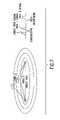
- FIG. 7illustrates impulse radio multipath effects in accordance with the present invention.
- FIG. 8illustrates the phase of the multipath pulse in accordance with the present invention.
- FIG. 9shows a representative block diagram of a full duplex impulse radio system, in accordance with the present invention.
- FIG. 10shows timing of transmitted and received pulses at a transceiver.
- FIG. 11shows contention zones between an impulse radio transmitter and receiver.
- FIG. 12shows a delay transmit technique to minimize the affect of contention zones between an impulse radio transmitter and receiver, in accordance with an embodiment of the present invention.
- FIG. 13shows a flow diagram for a pulse interleaving technique for full duplex impulse radio communications, in accordance with an embodiment of the present invention.
- FIG. 14shows a flow diagram for a burst interleaving technique for full duplex impulse radio communications, in accordance with an embodiment of the present invention.
- FIG. 15shows exemplary pulses for a further embodiment of the present invention using different pulse repetition frequencies for two communicating transceivers.
- FIG. 16illustrates the cross correlation process in accordance with the present invention.
- FIG. 17shows a representative illustration of an impulse radio transceiver for full duplex communications, in accordance with an embodiment of the present invention.
- FIG. 18shows a representative illustration of an impulse radio transceiver for full duplex communications, in accordance with another embodiment of the present invention.
- FIG. 19shows an exemplary block diagram of a transceiver implemented for synchronizing pulse interleaving, according to a preferred embodiment of the present invention.
- FIG. 20shows a flow diagram to implement a delay for pulse interleaved communications.
- Impulse radio technologyis widely applicable for wireless communications applications. Because impulse radio is not a continuous wave (CW) carrier-based system, the use of a subcarrier is an elegant, counter intuitive addition to the time domain impulse radio design. Signal-to-noise ratio is thereby improved considerably compared to non-subcarrier impulse radio transmissions.
- CWcontinuous wave
- Impulse radiosgenerally have: short duration pulses; center frequencies typically between 50 MHz and 10 gigahertz (GHz); ultrawide bandwidths of 100+% of the center frequency; multi-mile ranges with sub-milliwatt average power levels, even with low gain antennas; extremely low power spectral densities; lower cost than other sophisticated radio designs, especially spread spectrum systems; and excellent immunity to jamming from other systems and to multipath fading.
- center frequenciestypically between 50 MHz and 10 gigahertz (GHz); ultrawide bandwidths of 100+% of the center frequency
- multi-mile ranges with sub-milliwatt average power levels, even with low gain antennasextremely low power spectral densities
- lower cost than other sophisticated radio designs, especially spread spectrum systemsand excellent immunity to jamming from other systems and to multipath fading.
- Impulse radioshave exceptional multipath immunity and are relatively simple and less costly to build, especially in comparison to spread spectrum radios.
- Impulse radio systemsconsume substantially less power than existing conventional radios. Additionally, impulse radio systems occupy less space than existing portable telecommunications transceivers. Because of these characteristics, impulse radio is an optimal technology for a wide variety of applications, including personal communications systems and in-building communications systems.
- Section IIis directed to technology basics and provides the reader with an introduction to impulse radio concepts, as well as other relevant aspects of communications theory.
- Section mis directed full duplex for impulse radio communication systems. This section includes subsections relating to the theory of operation of full duplex for an impulse radio transceiver.
- this sectionis directed to technology basics and provides the reader with an introduction to impulse radio concepts, as well as other relevant aspects of communications theory.
- This sectionincludes subsections relating to Gaussian monocycle pulses, pulse trains of gaussian monocycle pulses, modulation, coding, and qualitative and quantitative characteristics of these concepts.
- Impulse radio transmittersemit short Gaussian monocycle pulses with a tightly controlled average pulse-to-pulse interval.
- Impulse radio transmittersuse pulse widths of between 20 and 0.1 nanoseconds (ns) and pulse-to-pulse intervals of between 2 and 5000 ns. These narrow monocycle pulses have inherently wide-band frequency characteristics.
- Impulse radio systemsuses pulse position modulation, with the actual pulse-to-pulse interval being varied on a pulse-by-pulse basis by two components: an information component and a pseudo-random code component.
- the pseudo-random codeis not necessary for energy spreading (because the impulses themselves are inherently wide-band), but rather for channelization, energy smoothing in the frequency domain, and jamming resistance.
- the impulse radio receiveris a direct conversion receiver with a cross correlator front end.
- the front endcoherently converts the electromagnetic pulse train to a baseband signal in one stage.
- the impulse radio receiverintegrates multiple pulses to recover each bit of the transmitted information.
- Gaussian monocycleswhich are also referred to herein as Gaussian monocycle pulses.
- a Gaussian monocycleis the first derivative of the Gaussian function.
- FIGS. 1A and 1Bshow a 2 GHz center frequency (i.e., a 0.5 ns pulse width) monocycle pulse in the time and frequency domains (see 102 and 104 , respectively).
- a 2 GHz center frequencyi.e., a 0.5 ns pulse width
- monocycleswhich are sometimes called impulses, are not gated sine waves.
- the Gaussian monocycle waveformis naturally a wide bandwidth signal, with the center frequency and the bandwidth completely dependent upon the pulse's width. In the time domain, the Gaussian monocycle is
- V ⁇ ( t )A ⁇ 2 ⁇ e ⁇ ⁇ t ⁇ ⁇ e - ( t ⁇ ) 2 described mathematically by:
- V ⁇ ( ⁇ )A ⁇ ⁇ ⁇ ⁇ 2 ⁇ 2 ⁇ ⁇ ⁇ ⁇ e ⁇ e ⁇ 2 ⁇ ⁇ 2 2
- the Gaussian monocycle envelopeis:
- fc1 2 ⁇ ⁇ ⁇ ⁇ ⁇ ⁇ Hz
- the 3 dB down points (power)are:
- Impulse radio systemsuse pulse trains, not single pulses, for communications. As described in detail in Section III below, the impulse radio transmitter produces and outputs a train of pulses for each bit of information.
- FIGS. 2A and 2Bare illustrations of a 1 mpps system with (uncoded, unmodulated) 1 ns pulses in the time and frequency domains (see 102 and 104 , respectively).
- this highly regular pulse trainproduces energy spikes (comb lines 204 ) at one megahertz intervals; thus, the already low power is spread among the comb lines 204 .
- This pulse traincarries no information and, because of the regularity of the energy spikes, might interfere with conventional radio systems at short ranges.
- impulse radio systemshave very low duty cycles so the average power in the time domain is significantly lower than the peak power in the time domain.
- the impulse transmitteroperates 0.1% of the time (i.e., 1 ns per microsecond ( ⁇ s)).
- Additional processingis needed to modulate the pulse train so that the impulse radio system can actually communicate information.
- the additional processingalso smooths the energy distribution in the frequency domain so that impulse radio transmissions (e.g., signals) interfere minimally with conventional radio systems.
- Amplitude and frequency/phase modulationare unsuitable for this particular form of impulse communications; the only suitable choice is pulse position modulation, which allows the use of a matched filter (i.e., cross correlator) in the receiver. As illustrated in FIG. 3 , a modulating signal changes the pulse repetition interval (PRI) in proportion to the modulation.
- PRIpulse repetition interval
- the first levelmight shift the generation of the pulse forward in time from the nominal by ⁇ picoseconds (ps); the second level might not shift the pulse position in time from the nominal at all; and the third level might delay the pulse by ⁇ ps.
- Analog modulationwould allow continuous deviations between PRI ⁇ and PRI+ ⁇ .
- pulse position modulationdistributes the energy over more frequencies.
- the modulation dither (d)is 100 ps
- the PRIis 1,000,000 Hertz (Hz) and the additional frequency components are: 999,800.04 Hz, 999,900.01 Hz, 1,000,100.01 Hz, and 1,000,200.04 Hz.
- Ditheris an impulse radio communications term for moving the position of a pulse in time.
- Transmitted energyis now distributed among more spikes (comb lines) in the frequency domain. If the total transmitted energy remains constant, the energy in each frequency spike decreases as the number of possible pulse positions increases. Thus, in the frequency domain, the energy is more smoothly distributed.
- the amount of time position modulation required for one-hundred percent modulationis calculated by the inverse of f C /4 (where f C is the center frequency). For a monocycle with a center frequency of 1.3 GHz, for example, this corresponds to ⁇ 157 (ps) of time position modulation. The spectrum-smoothing effects at this level of time dither is negligible.
- FIG. 4is a plot illustrating the impact of pseudo-random dither on energy distribution in the frequency domain.
- FIG. 4when compared to FIG. 2B , shows the impact of using a 256 position PN code relative to an uncoded signal.
- PN ditheringalso provides for channelization (channelization is a procedure employed to divide a communications path into a number of channels). In an uncoded system, differentiating between separate transmitters would be very hard. PN codes create channels, if the codes themselves are relatively orthogonal (i.e., there is low correlation and/or interference between the codes being used).
- an impulse radiodoes not depend on receiving every pulse.
- the impulse radio receiverperforms a correlating, synchronous receiving function (at the RF level) that uses a statistical sampling of many pulses to recover the transmitted information.
- Impulse radio receiverstypically integrate 200 or more pulses to yield the demodulated output.
- the optimal number of pulses over which the receiver integratesis dependent on a number of variables, including pulse rate, bit rate, jamming levels, and range.
- the PN codingalso makes impulse radio highly resistant to jamming from all radio communications systems, including other impulse radio transmitters. This is critical as any other signals within the band occupied by an impulse signal act as a jammer to the impulse radio. Since there are no unallocated 1+ GHz bands available for impulse systems, they must share spectrum with other conventional and impulse radios without being adversely affected.
- the PN codehelps impulse systems discriminate between the intended impulse transmission and transmissions from others.
- FIG. 5illustrates the result of a narrowband sinusoidal jamming (interference) signal 502 overlaying an impulse radio signal 504 .
- the input to the cross correlatorwould include that narrowband signal 502 , as well as the received ultrawide-band impulse radio signal 504 .
- the cross correlatorwould sample the jamming signal 502 with such regularity that the jamming signals could cause significant interference to the impulse radio receiver.
- the transmitted impulse signalis encoded with the PN code dither (and the impulse radio receiver is synchronized with that identical PN code dither) it samples the jamming signals randomly. According to the present invention, integrating over many pulses negates the impact of jamming.
- the pseudo-randomization in time of the receive processcreates a stream of randomly distributed values with a mean of zero (for jamming signals). Therefore, to eliminate the impact of jammers all that is necessary is to sample over enough pulses (i.e., integrate over a sufficiently large number of pulses) to drive the impact of the jamming signals to zero.
- Impulse radiois jam resistant because of its large processing gain.
- processing gainwhich quantifies the decrease in channel interference when wide-band communications are used, is the ratio of the bandwidth of the channel to the bandwidth of the information signal.
- a direct sequence spread spectrum system with a 10 kHz information bandwidth and a 16 MHz channel bandwidthyields a processing gain of 1600 or 32 dB.
- far greater processing gainsare achieved with impulse radio systems where, for the same 10 kHz information bandwidth and a 2 GHz channel bandwidth, the processing gain is 200,000 or 53 dB.
- the duty cycle(e.g., of 0.5%) yields a process gain of 28.3 dB.
- the process gainis generally the ratio of the bandwidth of a received signal to the bandwidth of the received information signal.
- the effective oversampling from integrating over multiple pulses to recover the information(e.g., integrating over 200 pulses) yields a process gain of 28.3 dB.
- a 2 GHz divided by a 10 mpps link transmitting 50 kilobits per second (kbps)would have a process gain of 49 dB, (i.e., 0.5 ns pulse width divided by a 100 ns pulse repetition interval would have a 0.5% duty cycle, and 10 mpps divided by a 50,000 bps would have 200 pulses per bit.)
- FIG. 6shows the “cross correlator transfer function” 602 . This represents the output value of an impulse radio receiver cross correlator for any given received pulse. As illustrated at 604 , the cross correlator's output is 0 volts when pulses arrive outside of a cross correlation window 606 . As a received pulse 608 slides through the window, the cross correlator output varies.
- the cross correlator's outputWhen the receiving system is synchronized with the intended transmitter, the cross correlator's output has a swing of between ⁇ 1 volt (as a function of the transmitter's modulation). Other in-band transmission would cause a variance to the cross correlator's output value. This variance is a random variable and can be modelled as a Gaussian white noise signal with a mean value of 0. As the number of interferers increases, the variance increases linearly. By integrating over a large number of pulses, the receiver develops
- Multipath fadingthe bane of sinusoidal systems, is much less of a problem (i.e., orders of magnitude less) for impulse systems than for conventional radio systems.
- Rayleigh fadingso noticeable in cellular communications, is a continuous wave phenomenon, not an impulse communications phenomenon.
- Pulses traveling between these intervalsdo not cause self-interference (in FIG. 7 , this is illustrated by the pulse traveling Path 2).
- pulses traveling grazing pathsas illustrated in FIG. 7 by the narrowest ellipsoid, create impulse radio multipath effects.
- the multipath pulsetravels one half width of a pulse width further, it increases the power level of the received signal (the phase of the multipath pulse will be inverted by the reflecting surface). If the pulse travels less than one half a pulse width further, it will create destructive interference as shown at 804 . For a 1 ns pulse, for example, destructive interference will occur if the multipath pulse travels between 0 and 15 cm (0 and 6 inches).
- a representative block diagram of a full duplex impulse radio communication systemis shown in FIG. 9 .
- a first transceiver (A) 902comprises a transmitter (T 1 ) 904 and a receiver (R 1 ) 906 .
- a second transceiver (B) 908comprises a transmitter (T 2 ) 910 and a receiver (R 2 ) 912 .
- the transceivers 902 and 908are separated by a propagation medium 914 , such as air, space, or other medium cable of propagating ultrawide-band signals.
- Transmitted impulse radio signals 916propagate through the propagation medium 914 between T 1 904 and R 2 912 , and between T 2 910 and R 1 906 .
- the purpose for full duplex transmission in an ultrawide band impulse radio systemis to provide two-way transmittal of information similar to telephony, as opposed to a walkie-talkie (i.e., a push-to-talk simplex operation). Since ultrawide band signals utilize the full electromagnetic spectrum, or at least a very large part of it, it is necessary to use some technique other than frequency domain duplexing, which is the conventional method. The inventors have therefore developed a pulse interleaving technique for full duplex impulse radio communications.
- transmitter T 1 904sends out a train of modulated pulses 1002
- receiver R 1 906would need to receive pulses 1004 transmitted from transmitter T 2 910 during the time periods between the pulses 1002 transmitted by T 1 .
- T 1 904is set to emit each pulse 1202 10 nanoseconds (ns) after R 1 906 receives a pulse 1204 from T 2 910 .
- This transmit delayis depicted in FIG. 12 . This reduces interference between the transmitter and the receiver at transceiver 1 , for example. If T 1 904 transmits after it receives a pulse, those pulses cannot interfere. Since T 1 904 has waited for over a whole period (one period is about 5 ns) before transmitting, most of the noise from the previous pulse has died down before the current pulse is transmitted. However, some contention zones 1206 will still exist between the two transmitters.
- the easiest way to resolve these contention zones 1206is to permit the first transceiver to have a choice of say, 10 ns or 100 ns of delay before transmitting after receiving a pulse. This removes the interference at point 1208 for example, by pushing (position in time) pulse 1210 up to point 1212 so that the self-interference is avoided.
- each pulseis also time dither coded as described above. They are shown here as un-time dither coded for simplicity. Thus, time dither coding further serves to remove the interface 1208 .
- T 1 904would begin transmitting to R 2 912 , as shown at a step 1302 .
- R 2 912scans for detection and acquires lock through its scanning mechanism (see step 1304 ). Once it acquires lock (see step 1306 ), its accompanying transmitter (T 2 910 ) can begin transmitting, as shown at a step 1308 .
- R 1 906then scans for detection, at step 1310 . If R 1 906 happens to be in a contention zone, then it will never acquire lock to T 2 910 .
- R 1 906must wait for an acknowledge message (ACK) 1306 to be conveyed to it by T 1 904 before it knows whether to use the 10 ns or the 100 ns transmitter receive timing delay. If it never receives, or after a certain time does not receive the ACK that R 1 906 has acquired T 2 910 , then T 2 910 times-out and shifts its transmitted pulse timing by 100 ns, for example, and tries again. These steps are shown generally by a conditional loop at steps 1312 , 1314 , 1316 and 1318 .
- R 2 912does acquire lock (i.e., receives an ACK from T 1 904 sent at step 1320 ) as shown at step 1322 , T 2 910 will transmit a return ACK at step 1324 , a link is established, and the transceivers are in lock.
- the timeoutis preferably the maximum time period required for R 2 912 to scan for a pulse from T 1 904 over the entire modulo of the dither code. For a 256 bit code, and a fairly small code dither of 10 ns a timeout can take up to 20 seconds. Timeout is only done for an initial lock. A timeout is not needed if the transceivers switch codes or delay values. Because of the simplicity in implementation of the pulse interleave technique, pulse interleave full duplex is very economical for many communication applications, such as telemetry and transponder-type systems. In the preferred embodiment, the receiver can stay on so that a cold start is not necessary.
- the mobile environmentpresents unique contention zone problems. Therefore, the following embodiments deal with the mobile environment explicitly, and are specifically directed at providing immunity to dead or contention zone problems.
- T 1 904starts the process by transmitting a burst (see step 1402 ), which, for example, could be 10 microseconds in length.
- each burstcontains 20 pulses at a 2 megapulse per second rate, or 50 pulses at a 5 megapulse rate.
- This first transmitted burstis received by R 2 912 after a certain amount of time passes due to propagation delay (i.e., range delay) and scanning delay by R 2 912 (see step 1404 ).
- Range delaycorresponds to about 5.2 microseconds per mile (approximately 5,200 feet) or about one foot per nanosecond.
- R 2acquires lock (see step 1406 ) and then T 2 910 transmits its burst containing information modulation (at step 1408 ), and after the same range delay, R 1 scans for detection (step 1410 ) and acquires lock (step 1412 ). If the timing between the bursts is sufficient, then under no circumstance(s) of position or range between the transceivers do the bursts collide. The criterion is that the delay between bursts be sufficient to accommodate the round trip delay and burst width. In practice, the burst should be as far away as possible before using up all the margin of receive time in this receiver before it will be required to transmit again. The transceivers then swap acquisition messages, as shown at steps 1414 , 1416 , 1418 and 1420 , to complete the locking process.
- a further embodiment of the present inventionuses code division multiple access (CDMA) for achieving full duplex communication in an ultrawide band impulse radio system.
- CDMAcode division multiple access
- T 1 904 and T 2 910are operated with different time dither codes, with dither windows nearly equalling the full frame so that each successive pulse can appear anywhere within the period separating the pulses.
- the dither windowis the period within which a monocycle can occur when position modulated by a dither code.
- T 1 904 and T 2 910can even use the same dither code because a time delay between them permits decorrelation. Typically, however, they would be operated on different time dither codes.
- T 1 904generates a blanking pulse that prevents receiving any energy within a certain amount of time after transmission, for example, 10 ns. This allows the antennas in the local environment to ring down or dampen energy for opening the receiver for possible received pulse. For example, a pulse width of 0.5 ns (or center frequency of 2 gigahertz), with a period of 200 ns (which is the repetition rate of 5 megapulses per second), produces a cycle of 1 in 400 (i.e., 0.25%).
- a blanking pulse equalling the transmitted pulse emittedis, however, not entirely effective. There is still sufficient energy ringing down in the environment and in the antenna that may cause significant self-interference. Statistically, pulses can align themselves perfectly in only about 1 in 400 pulses. The blanking window of 10 ns increases the probability of a received pulse being within that blanking window, up to 1%. A 1% probability means that 1% of the energy is thrown away by the receiver. A loss of only 1% of transmitted energy is a very small penalty to exact to allow for a full duplex operation. This 1% reduction likely unmeasurable.
- a still further embodimentis frequency division multiple access (FDMA), where the word “frequency” stands for pulse repetition frequency, which distinguishes this term from that used in continuous wave FM systems.
- FIG. 15shows exemplary pulses for this embodiment, in which T 1 904 is operated for example, at 1 megapulse per second (represented by microsecond pulses 1502 (numbers 1 , 2 , 3 , 4 , 5 , 6 and so on). Assuming T 2 910 is operating on, about 0.85 microseconds per period (see pulses 1504 ), after six pulses the two will come into alignment and be approximately settled. But after that time, however, all of the pulses miss.
- FDMAfrequency division multiple access
- the timed codingis confined to a relatively narrow window (say 4 ns, which is used for a 2 gigahertz center frequency system) then no matter what the placement of the two transceivers relative to each other, only one in six pulses will collide with each other.
- the repetition rate difference between the twowould be such that only one in a hundred would cause a collision 1506 . That one in a hundred can be blanked out (similar to the preceding example), which would again cause a 1% in reduction in power available to the receiver.
- Blankingcan be implemented in many ways. Discrete logic can be used to determine when received pulses and transmitted pulses of two different pulse repetition rates will interfere or occur too close in time. Interference is avoided by gating off one of the trigger signals (for example).
- This FDMA embodimenthas some of the advantages of the pulse interleaving embodiment, such as 100% availability of the transmitter.
- the pulse interleaving embodimentrequires the transmitter to be turned off for a significant fraction at the transmitting cycle.
- the disadvantagebeing, for the same average of transmitted power, the pulse power has to be that much higher to make up for it.
- the duty cycle in the first examplewas on the order of 33%. Therefore the pulse power (i.e., the instantaneous pulse power), would have to be 66% larger.
- This last embodimentshares the advantages of pulse interleave—100% availability of the carrier—but it is never turned off on transmit. On receiving however, the periodic self-interference is taken care of by blanking, as in the previous example, reducing the received power availability by only 1%, a perfectly acceptable number.
- the method used to provide for isolation between a transmitter and a receiver for a full duplex impulse radio linkis different than for conventional radios because conventional radios operate using continuous wave carrier frequencies. These carrier frequencies can be very narrow-band and as such, frequency domain techniques can be used to isolate the transmitter from the receiver in the same view. Low pass filters can be used on the transmitter to prevent spurious energy from getting into a receiver, which is operated at a slightly higher frequency. Conversely, a high pass filter is used to eliminate power from the transmitter from getting into the receiver. This conventional filtering, however, cannot effectively be applied to impulse radio systems because the transmitter and receiver use the same pulse with monocycle.
- FIG. 16Two monocycles pulses with different center frequencies are shown in FIG. 16 .
- a long monocycle 1602has a low frequency content, and a shorter monocycle 1604 has a higher center frequency. Although these two pulses differ in center frequency by nearly 3 to 1, they still significantly overlap. Therefore, even in this case a filter can be used to provide some isolation between a transmitter and a receiver, operating at one center frequency (f C1 ) on the uplink and different center frequency (f C2 ) on the downlink. In this embodiment contention is completely eliminated by the fact that different center frequencies are used in operation.
- the dither windowis the period within which a monocycle can occur as positioned by a dither code.
- the dither windowis 5 ns wide.
- Each dither windowis separated by 200 ns.
- a subsequent monocyclecan occur anywhere within the next dither window, and at a minimum, 200 ns later.
- the concentration of pulses in a relatively narrow time zone in each frame, where a frame is the nominal interpulse intervalcontributes to increased interference with conventional services, as well as increased interference with like transceivers.
- the increased interferenceis an undesirable consequence of the difficulty of making wider dither windows.
- the difficultylies in the fact that long time delays are difficult to make with low jitter. Because this is a coherent communication scheme, low jitter is important for efficient conversion of a pulse and for good signal-to-noise ratio at low RF power levels.
- the pulse interleave method, burst interleave method, and the pulse repetition rate multiple access techniquesare all three consequences of this concentration of energy in a small time zone.
- the constraintsare less on the system until at a limit, a whole frame can be a target for a gain given monocycle (i.e., in a 200 ns average pulse rate, a pulse can appear anywhere within that 200 ns).
- a brief off-time between dither windowsis desirable.
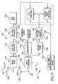
- a preferred embodiment of an impulse radio transmitter 904 or 910 of an impulse radio communication systemwill now be described with reference to FIG. 17 .
- the transmitter 1700comprises a time base 1702 that generates a periodic timing signal 1704 , which is provided to a time delay modulator 1706 .
- the time delay modulator 1706modulates the periodic timing signal 1704 with an information signal 1708 from an information source, to generate a modulated timing signal 1710 .
- the modulated timing signal 1710is provided to a code time modulator 1712 that dithers the modulated timing signal 1710 using a pseudo noise code.
- the code time modulator 1712outputs a modulated, coded timing signal 1714 to an output stage 1716 .
- the output stage 1716uses the modulated, coded timing signal 1714 as a trigger to generate electrical monocycle pulses (not shown).
- the electrical monocycle pulsesare sent to a transmit antenna 1718 via a transmission line 1720 coupled thereto.
- the electrical monocycle pulsesare converted into propagating electromagnetic pulses 1722 by the transmit antenna 1718 .
- a detailed description of various impulse radio transmittersis included in the '973 application.
- An impulse radio receiver 1701will now described with reference to FIG. 17 .
- An impulse radio receiver (hereafter called the receiver) 1701comprises a receive antenna 1726 for receiving a propagated impulse radio signal 1724 .
- a received signalis input to a cross correlator 1728 via a receiver transmission line 1730 , coupled to the receive antenna 1726 .
- the receiver 1701also comprises a decode timing modulator/decode source 1732 and an adjustable time base 1734 .
- the adjustable time base 1734can comprise a voltage controlled oscillator or a variable delay generator, as would be apparent to a person skilled in the art.
- the decode timing modulator/decode source 1732(hereafter called the decode timing modulator) generates a decode signal 1736 corresponding to the PN code used by the associated impulse radio transmitter (not shown) that transmitted the propagated signal 1724 .
- the adjustable time base 1734generates a periodic timing signal 1738 that comprises a train of template signal pulses having waveforms substantially equivalent to each pulse of the received signal 1724 .
- the detection process performed by the cross correlator 1728comprises a cross correlation operation of the received signal 1724 with the decode signal 1736 . Integration over time of the cross correlation generates a baseband signal 1740 .
- the baseband signal 1740is demodulated by a demodulator 1742 to yield a demodulated information (signal) 1744 .
- the demodulated information signal 1744is substantially identical to the information signal of the transmitter that sent the received signal 1724 .
- the baseband signal 1740is also input to a lowpass filter 1746 .
- the lowpass filter 1746generates an error signal 1748 for an acquisition and lock controller 1750 to provide minor phase adjustments to the adjustable time base 1734 .
- a detailed description of an impulse radio receiveris included in the '973 application.
- FIG. 18is a transceiver block diagram for the burst interleave embodiment of the present invention.
- a transmitter burst controller 1802 and a receiver burst controller 1804are added to the basic architecture of the transceiver of FIG. 17 .
- These two controllersare state machines that can be hardwired or programmably controlled (using EEPROMS, or the like) to time position the modulated, coded timing signal 1714 and to time modulate the periodic timing signal 1738 , respectively, in accordance with the burst interleave operation described above.
- the delay required for the pulse interleave embodiment of the present inventionis determined and provided by the acquisition and lock controller 1750 .
- the pulse repetition rate, dither window andare hardwired or programmably controlled into the burst controllers 1802 , 1804 and the acquisition and lock controller 1750 , for example.
- Other control features and modifications to the disclosed transceiver components/controllerswould be apparent to a person skilled in the relevant art without departing from the scope of the present invention.
- each receivermust measure the time between the reception of a pulse from another transceiver and the trigger to its own transmitter (this which can be accomplished with conventional circuitry).
- a minimum limite.g. 20 ns
- itnotifies the other transceiver to synchronously change its receive timing (and the first transceiver will change its transmit timing) at, for example, the first pulse of the second code modulo from now.
- “now”is a point in time determined by the first transceiver as a reference point in time that is communicated to the second transceiver (or otherwise inferred by the second transceiver) for synchronization.
- modulosare long enough to encode at least one whole bit, and that therefore can serve as a trigger for the counting of whole modulos. Since the coder keeps track of the pulse “count” in order to apply the correct time dither to the decoder, this method can indirectly identify individual pulses for the purpose of synchronization.
- a mechanism to accomplish the synchronization and locking for operation of pulse interleavecan be discrete logic, but can be readily implemented by a digital signal processor (DSP) with minimal programming that would be apparent to a person skilled in the relevant art based on this disclosure of the pulse interleave functionality.
- DSPdigital signal processor
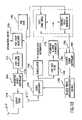
- FIG. 19shows an exemplary block diagram of a transceiver implemented using a DSP for synchronizing pulse interleaving, according to a preferred embodiment of the present invention. This figure shows on enough detail of a transceiver to describe the synchronization.
- a DSP 1902is used to determine whether the transmitter trigger signal 1904 is too close to the receiver trigger signal 1906 , using a block 1908 , labeled “measure time difference.”
- the DSP 1902delays the transmitter trigger signal 1904 by 100 ns (for example) by sending a delay control signal 1910 to a delay block 1912 to outputs a delayed trigger signal 1914 , which is provided to the transmitter.
- the DSP 1902also outputs massaging information 1916 to be modulated with the data to accomplish the synchronization with the other transceiver.
- a analog-to-digital (A/D) converteris shown at 1918 , because the DSP need to process the cross correlator output in the digital domain.
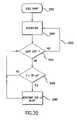
- FIG. 20shows a flow diagram of the DSP operation to implement a delay for pulse interleaved communications.
- the transceiversacquire lock 2004 , as described above. If a time (t) between a transmitted pulse and a received pulse is less than 20 ns, as shown at a decisional block 2006 , a 100 ns delay is negotiated between the two transceivers at 2008 . This is termed a negotiation, since either transceiver can perform the necessary delay. The negotiation is carried out via massaging 1916 . If lock is lost, as determined by decisional block 2010 , acquisition must be repeated, as shown at 2012 .
- the transmitter and receiver comprising a transceiverare operated at two different rates, then it is not possible to “interleave” the pulses, since they “beat” with each other (i.e., the timing of the pulse trains will periodically cause the transmitted and received pulses to periodically coincide).
- a mechanism similar to the detector described abovecan be used to detect the minimum pulse separation condition. However, this signal will be employed in a different way: either to blank the trigger to the correlator or to the transmitter. Either response will have the desired result of preventing self interference, but they have different tradeoffs in a communications system.
- the transmitterIf the transmitter is blanked, it will reduce the transmitted power and interfere with the carrier which would be received by another transceiver, due to the gaps in the carrier which result from the blanking action. However, it increases the received power to the first transceiver, since it will not have to throw away the pulses which occur within this minimum separation window as would be the case if the receiver is blanked instead.
- the communications methods described herehave been observed to be usable not only using radio (electromagnetic) impulsive waveforms, but also may use acoustic signals.
- the principle differences in the latter approachare: (1) frequency of operation and (2) signal transmission.
- the frequency of operationis primarily between a few tens of Hertz (e.g., pulses of a duration of several tens of milliseconds), up to a few hundred Megahertz (e.g., pulses with durations of a few nanoseconds).
- Acoustic transducersare employed in the acoustic approach rather than the antennas, which are used for the radio approach.
- the signal characteristics of the transducersare similar to the signal characteristics required by the antennas used in the radio approach in that they must be capable of transmitting and/or receiving waveforms with bandwidths of ⁇ 100% of the center frequency (without more than a few percent dispersion, and with good conversion gain).
- Transducersmay be made from a material called Kynar Film supplied by Pennwalt Corporation in Valley Forge, Pa. The geometry of a transducer made from this type as would become apparent to a person skilled in the relevant art.
Landscapes
- Engineering & Computer Science (AREA)
- Computer Networks & Wireless Communication (AREA)
- Signal Processing (AREA)
- Dc Digital Transmission (AREA)
Abstract
Description
| Table of Contents |
| I. | Overview | 9 |
| II. | 10 | |
| A. | Gaussian Monocycle | 11 |
| B. | 12 | |
| C. | Modulation | 13 |
| D. | Coding for Energy Smoothing and Channelization | 14 |
| E. | Reception and Demodulation | 14 |
| F. | Jam Resistance | 15 |
| G. | Processing Gain | 16 |
| H. | Capacity | 17 |
| I0 | Multipath and Propagation | 18 |
| IIIA | Full Duplex for Impulse Radio Communication Systems | 19 |
| A. | The Impact of the Width of the Dither Window on | 25 |
| System Performance | ||
| IVA | Exemplary Transceiver Hardware | 26 |
| A0 | Transmitter | 26 |
| B0 | Receiver | 27 |
| C0 | Time Hand-off | 28 |
| D0 | Differential Rate Duplex | 30 |
| V. | Other Considerations | 31 |
| VI. | Conclusion | 31 |
I. Overview
described mathematically by:
- Where, A is the peak amplitude of the pulse,
- t is time, and
- τ (tau) is a time decay constant.
In the frequency domain, the Gaussian monocycle envelope is:
The center frequency is then:
flower=0.319c; fupper=1.922c.
Relative to c, the 3 dB down points (power) are:
fc=2.0GHz; Δfc=3.2GHz.
the “0.5 ns” pulse shown in
an estimate of the transmitted signal's modulation value. Mathematically:
- Where N=number of interferers,
- σ is the variance of all the interferers to a single cross correlation, and
- Z is the number of pulses over which the receiver integrates to recover the modulation.
Claims (10)
Priority Applications (2)
| Application Number | Priority Date | Filing Date | Title |
|---|---|---|---|
| US10/411,090US7321611B2 (en) | 1994-09-20 | 2003-04-11 | Method and transceiver for full duplex communication of ultra wideband signals |
| US11/586,066US7539237B2 (en) | 1996-12-06 | 2006-10-25 | Fast locking mechanism for channelized ultrawide-band communications |
Applications Claiming Priority (6)
| Application Number | Priority Date | Filing Date | Title |
|---|---|---|---|
| US08/309,973US5677927A (en) | 1994-09-20 | 1994-09-20 | Ultrawide-band communication system and method |
| US08/428,489US5687169A (en) | 1995-04-27 | 1995-04-27 | Full duplex ultrawide-band communication system and method |
| US08/761,602US5832035A (en) | 1994-09-20 | 1996-12-06 | Fast locking mechanism for channelized ultrawide-band communications |
| US15857098A | 1998-09-22 | 1998-09-22 | |
| US09/458,010US6549567B1 (en) | 1994-09-20 | 1999-12-10 | Full duplex ultrawide-band communication system and method |
| US10/411,090US7321611B2 (en) | 1994-09-20 | 2003-04-11 | Method and transceiver for full duplex communication of ultra wideband signals |
Related Parent Applications (2)
| Application Number | Title | Priority Date | Filing Date |
|---|---|---|---|
| US15857098AContinuation | 1994-09-20 | 1998-09-22 | |
| US09/458,010ContinuationUS6549567B1 (en) | 1994-09-20 | 1999-12-10 | Full duplex ultrawide-band communication system and method |
Related Child Applications (1)
| Application Number | Title | Priority Date | Filing Date |
|---|---|---|---|
| US11/586,066ContinuationUS7539237B2 (en) | 1996-12-06 | 2006-10-25 | Fast locking mechanism for channelized ultrawide-band communications |
Publications (2)
| Publication Number | Publication Date |
|---|---|
| US20030189975A1 US20030189975A1 (en) | 2003-10-09 |
| US7321611B2true US7321611B2 (en) | 2008-01-22 |
Family
ID=28678855
Family Applications (1)
| Application Number | Title | Priority Date | Filing Date |
|---|---|---|---|
| US10/411,090Expired - Fee RelatedUS7321611B2 (en) | 1994-09-20 | 2003-04-11 | Method and transceiver for full duplex communication of ultra wideband signals |
Country Status (1)
| Country | Link |
|---|---|
| US (1) | US7321611B2 (en) |
Cited By (13)
| Publication number | Priority date | Publication date | Assignee | Title |
|---|---|---|---|---|
| US20090060797A1 (en)* | 2002-12-30 | 2009-03-05 | The Regents Of The University Of California | Fluid control structures in microfluidic devices |
| US7570196B1 (en)* | 2007-05-01 | 2009-08-04 | L-3 Communications Corporation | Apparatus, method, computer program product and system providing asynchronous transmission of communications data using time-gated techniques |
| US20090252065A1 (en)* | 2006-07-28 | 2009-10-08 | Hang Zhang | Multi-hop network topology system and method |
| US20090303895A1 (en)* | 2006-07-28 | 2009-12-10 | Nortel Networks Limited | System and method for wireless multi-hop network synchronization and monitoring |
| US9713010B2 (en) | 2012-05-13 | 2017-07-18 | Amir Keyvan Khandani | Full duplex wireless transmission with self-interference cancellation |
| US10063364B2 (en) | 2013-11-30 | 2018-08-28 | Amir Keyvan Khandani | Wireless full-duplex system and method using sideband test signals |
| US10177896B2 (en) | 2013-05-13 | 2019-01-08 | Amir Keyvan Khandani | Methods for training of full-duplex wireless systems |
| US10333593B2 (en) | 2016-05-02 | 2019-06-25 | Amir Keyvan Khandani | Systems and methods of antenna design for full-duplex line of sight transmission |
| US10334637B2 (en) | 2014-01-30 | 2019-06-25 | Amir Keyvan Khandani | Adapter and associated method for full-duplex wireless communication |
| US10700766B2 (en) | 2017-04-19 | 2020-06-30 | Amir Keyvan Khandani | Noise cancelling amplify-and-forward (in-band) relay with self-interference cancellation |
| US11012144B2 (en) | 2018-01-16 | 2021-05-18 | Amir Keyvan Khandani | System and methods for in-band relaying |
| US11057204B2 (en) | 2017-10-04 | 2021-07-06 | Amir Keyvan Khandani | Methods for encrypted data communications |
| US12345802B2 (en)* | 2020-09-17 | 2025-07-01 | Texas Instruments Incorporated | Doppler processing in frequency-modulated continuous wave radar systems using dither |
Families Citing this family (23)
| Publication number | Priority date | Publication date | Assignee | Title |
|---|---|---|---|---|
| US20050058114A1 (en)* | 2003-09-15 | 2005-03-17 | John Santhoff | Ultra-wideband communication protocol |
| US20050058153A1 (en)* | 2003-09-15 | 2005-03-17 | John Santhoff | Common signaling method |
| JP3847289B2 (en)* | 2003-11-10 | 2006-11-22 | 株式会社半導体理工学研究センター | Pulse-based communication system |
| FI115579B (en)* | 2003-11-17 | 2005-05-31 | Nokia Corp | Pulse-based communication |
| FI116496B (en) | 2003-11-17 | 2005-11-30 | Nokia Corp | Broadband Communication procedure |
| US20050169389A1 (en)* | 2004-02-04 | 2005-08-04 | Fischer Gerald R. | Increased user capacity ultra wideband (UWB) signal formatting scheme |
| KR100593259B1 (en) | 2004-02-24 | 2006-06-26 | 광주과학기술원 | Super-orthogonal Convolutional Coding Ultra-Broadband Impulse Radio System Using Interleaving and Its Encoding / Decoding Method |
| WO2005088850A1 (en) | 2004-03-17 | 2005-09-22 | Brother Kogyo Kabushiki Kaisha | Position detection system, response device and query device, radio communication system, position detection method, position detection program, and information recording medium |
| US7299042B2 (en)* | 2004-07-30 | 2007-11-20 | Pulse-Link, Inc. | Common signaling method and apparatus |
| CN100593919C (en)* | 2004-08-05 | 2010-03-10 | 松下电器产业株式会社 | Pulse signal demodulation apparatus |
| US8811456B2 (en) | 2006-04-19 | 2014-08-19 | Qualcomm Incorporated | Apparatus and method of low latency multi-hop communication |
| EP2504996A1 (en)* | 2009-11-25 | 2012-10-03 | Thirel B.V. | Card sharing countermeasures |
| US9997830B2 (en) | 2012-05-13 | 2018-06-12 | Amir Keyvan Khandani | Antenna system and method for full duplex wireless transmission with channel phase-based encryption |
| AU2012385953A1 (en)* | 2012-07-27 | 2015-02-26 | Adaptive Spectrum And Signal Alignment, Inc. | Management system and methods of managing time-division duplex (TDD) transmission over copper |
| CN108599867B (en)* | 2018-03-29 | 2021-02-02 | 上海交通大学 | Optical digital signal receiving device based on waveform matching |
| US11742883B2 (en) | 2020-10-16 | 2023-08-29 | Deere & Company | Adaptive narrowband interference rejection for satellite navigation receiver |
| US11671133B2 (en) | 2020-10-16 | 2023-06-06 | Deere & Company | Adaptive narrowband and wideband interference rejection for satellite navigation receiver |
| US11764862B2 (en) | 2020-10-16 | 2023-09-19 | Deere & Company | Adaptive narrowband interference rejection for satellite navigation receiver |
| WO2022147378A2 (en)* | 2020-12-28 | 2022-07-07 | Deere & Company | Adaptive narrowband and wideband interference rejection for satellite navigation receiver |
| US12379508B2 (en) | 2021-12-30 | 2025-08-05 | Deere & Company | Satellite navigation receiver with aggregate channel digital baseband processing |
| WO2023158507A1 (en)* | 2022-02-18 | 2023-08-24 | Deere & Company | A multi-constellation, multi-frequency gnss system for interference mitigation |
| US12066551B2 (en) | 2022-02-18 | 2024-08-20 | Deere & Company | Multi-constellation, multi-frequency GNSS system for interference mitigation |
| US12153143B2 (en)* | 2022-02-18 | 2024-11-26 | Deere & Company | Multi-constellation, multi-frequency GNSS system for interference mitigation |
Citations (67)
| Publication number | Priority date | Publication date | Assignee | Title |
|---|---|---|---|---|
| FR962130A (en) | 1950-06-02 | |||
| US3593138A (en) | 1968-07-31 | 1971-07-13 | Nasa | Satellite interlace synchronization system |
| US3659203A (en) | 1970-06-15 | 1972-04-25 | Sperry Rand Corp | Balanced radiator system |
| US3662316A (en) | 1971-03-12 | 1972-05-09 | Sperry Rand Corp | Short base-band pulse receiver |
| US3686669A (en) | 1970-04-24 | 1972-08-22 | William J Toulis | Detection and classification system utilizing unipolar pulses |
| US3720950A (en) | 1967-11-28 | 1973-03-13 | North American Rockwell | Time-domain correlator for spatial filtering in a pulsed energy system |
| US3721912A (en) | 1971-04-19 | 1973-03-20 | Sperry Rand Corp | Short time electromagnetic wave signal sampling system |
| US3728632A (en) | 1971-03-12 | 1973-04-17 | Sperry Rand Corp | Transmission and reception system for generating and receiving base-band pulse duration pulse signals without distortion for short base-band communication system |
| US3737776A (en) | 1971-06-09 | 1973-06-05 | J Fletcher | Two carrier communication system with single transmitter |
| US3739392A (en) | 1971-07-29 | 1973-06-12 | Sperry Rand Corp | Base-band radiation and reception system |
| US3750025A (en) | 1971-04-26 | 1973-07-31 | Sperry Rand Corp | Energy amplifying selector gate for base-band signals |
| US3757290A (en)* | 1971-03-12 | 1973-09-04 | Sperry Rand Corp | Automatic vehicle monitoring system |
| US3772697A (en) | 1971-04-19 | 1973-11-13 | Sperry Rand Corp | Base-band pulse object sensor system |
| US3794996A (en) | 1972-07-12 | 1974-02-26 | Sperry Rand Corp | Stable base-band superregenerative selective receiver |
| US3864635A (en) | 1972-08-04 | 1975-02-04 | Westinghouse Electric Corp | Correlation receiver with rapid frequency, time and phase acquisition |
| US3866230A (en)* | 1973-03-02 | 1975-02-11 | Bendix Corp | Single channel communication system |
| US4122393A (en) | 1977-05-11 | 1978-10-24 | Ncr Corporation | Spread spectrum detector |
| US4150375A (en) | 1978-03-02 | 1979-04-17 | Sperry Rand Corporation | Interferometric protective system for vehicles |
| DE2816353A1 (en) | 1978-04-12 | 1979-10-25 | Prakla Seismos Gmbh | Acoustic pulsed communications system - sends and receives sound waves via ground, using signals whose value depends on amplitude, frequency or phase, generated by vibrator |
| US4279018A (en) | 1979-03-06 | 1981-07-14 | Nasa | PN Lock indicator for dithered PN code tracking loop |
| US4291409A (en) | 1978-06-20 | 1981-09-22 | The Mitre Corporation | Spread spectrum communications method and apparatus |
| US4361890A (en) | 1958-06-17 | 1982-11-30 | Gte Products Corporation | Synchronizing system |
| DE3131186A1 (en) | 1981-08-06 | 1983-02-24 | Siemens AG, 1000 Berlin und 8000 München | RECEIVER FOR PSEUDO-FAULTY PHASE-MODULATED SIGNALS |
| US4423517A (en) | 1980-01-21 | 1983-12-27 | Matsushita Electric Industrial Co., Ltd. | Code sequence synchronization system for spread spectrum communication receiver |
| US4545061A (en) | 1962-09-28 | 1985-10-01 | Sylvania Electric Products Inc. | Synchronizing system |
| US4550414A (en) | 1983-04-12 | 1985-10-29 | Charles Stark Draper Laboratory, Inc. | Spread spectrum adaptive code tracker |
| US4641317A (en) | 1984-12-03 | 1987-02-03 | Charles A. Phillips | Spread spectrum radio transmission system |
| US4665404A (en) | 1983-10-24 | 1987-05-12 | Offshore Navigation, Inc. | High frequency spread spectrum positioning system and method therefor |
| US4688232A (en) | 1985-03-08 | 1987-08-18 | International Computers Limited | Decoder for Manchester encoded data |
| US4695752A (en) | 1982-01-11 | 1987-09-22 | Sperry Corporation | Narrow range gate baseband receiver |
| US4743906A (en) | 1984-12-03 | 1988-05-10 | Charles A. Phillips | Time domain radio transmission system |
| US4803726A (en) | 1986-12-31 | 1989-02-07 | Motorola, Inc. | Bit synchronization method for a digital radio telephone system |
| US4813057A (en) | 1984-12-03 | 1989-03-14 | Charles A. Phillips | Time domain radio transmission system |
| US4937580A (en) | 1988-05-19 | 1990-06-26 | Trustees Of Dartmouth College | Geophysical radar apparatus and method |
| US4984247A (en) | 1988-09-29 | 1991-01-08 | Ascom Zelcom Ag | Digital radio transmission system for a cellular network, using the spread spectrum method |
| US5008899A (en) | 1989-07-03 | 1991-04-16 | Futaba Denshi Kogyo Kabushiki Kaisha | Receiver for spectrum spread communication |
| WO1991006155A1 (en) | 1989-10-12 | 1991-05-02 | Agence Spatiale Europeenne | Code acquisition method and circuit for a spread spectrum signal receiver |
| US5018165A (en)* | 1990-03-21 | 1991-05-21 | Andrew Corporation | Communication system using spread spectrum and leaky transmission line |
| US5031191A (en) | 1989-05-17 | 1991-07-09 | Sanyo Electric Co., Ltd. | Spread spectrum signal demodulation circuit |
| US5099495A (en) | 1989-03-24 | 1992-03-24 | Nobuo Mikoshiba | Spread spectrum communication device |
| US5105437A (en) | 1990-07-26 | 1992-04-14 | Unisys Corporation | Programmable digital acquisition and tracking controller |
| US5111451A (en)* | 1989-10-27 | 1992-05-05 | Crystal Semiconductor | Method and apparatus for synchronizing an optical transceiver over a full duplex data communication channel |
| US5128961A (en) | 1989-11-24 | 1992-07-07 | Daikin Industries, Ltd. | Distance measurement method and apparatus, and relative position measurement apparatus |
| US5140610A (en) | 1991-10-08 | 1992-08-18 | The United States Of America As Represented By The Secretary Of The Army | FM video data link spectrum spreading |
| US5148174A (en) | 1991-02-13 | 1992-09-15 | Geophysical Survey Systems, Inc. | Selective reception of carrier-free radar signals with large relative bandwidth |
| US5173923A (en) | 1991-11-22 | 1992-12-22 | Bell Communications Research, Inc. | Spread-time code division multiple access technique with arbitrary spectral shaping |
| US5177768A (en) | 1991-11-22 | 1993-01-05 | Bell Communications Research, Inc. | Spread-time code division multiple access technique with arbitrary spectral shaping |
| US5222098A (en) | 1990-06-15 | 1993-06-22 | Futaba Denshi Kogyo K.K. | Spectrum spread communication system |
| US5222103A (en) | 1991-01-02 | 1993-06-22 | Gte Laboratories Incorporated | Differential quadrature phase shift keying encoder for subcarrier systems |
| US5268926A (en) | 1991-09-11 | 1993-12-07 | Societe Nationale D'etude Et De Construction De Moteurs D'aviation "S.N.E.C.M.A." | Method and apparatus for the simultaneous transmission of separate data signals |
| US5317441A (en)* | 1991-10-21 | 1994-05-31 | Advanced Micro Devices, Inc. | Transceiver for full duplex signalling on a fiber optic cable |
| US5329558A (en) | 1991-04-12 | 1994-07-12 | Telefonaktiebolaget L M Ericsson | Method of synchronizing a radio receiver with an incoming radio signal |
| US5337054A (en) | 1992-05-18 | 1994-08-09 | Anro Engineering, Inc. | Coherent processing tunnel diode ultra wideband receiver |
| US5363108A (en) | 1984-12-03 | 1994-11-08 | Charles A. Phillips | Time domain radio transmission system |
| US5400359A (en) | 1992-03-23 | 1995-03-21 | Sharp Kabushiki Kaisha | Spread spectrum communication system and an apparatus for communication utilizing this system |
| US5404355A (en) | 1992-10-05 | 1995-04-04 | Ericsson Ge Mobile Communications, Inc. | Method for transmitting broadcast information in a digital control channel |
| US5442646A (en) | 1994-02-01 | 1995-08-15 | The Mitre Corporation | Subcarrier communication system |
| US5469470A (en) | 1993-01-08 | 1995-11-21 | Ricoh Company Ltd. | Spread spectrum communication system using two-predetermined-code pseudo-noise signals |
| US5623487A (en) | 1995-05-19 | 1997-04-22 | Stanford Telecommunications, Inc. | Doubly orthogonal code and frequency division multiple access communication system |
| US5677927A (en) | 1994-09-20 | 1997-10-14 | Pulson Communications Corporation | Ultrawide-band communication system and method |
| US5687169A (en) | 1995-04-27 | 1997-11-11 | Time Domain Systems, Inc. | Full duplex ultrawide-band communication system and method |
| US5717713A (en) | 1994-11-18 | 1998-02-10 | Stanford Telecommunications, Inc. | Technique to permit rapid acquisition and alert channel signalling for base station-to-user link of an orthogonal CDMA (OCDMA) communication system |
| US5745525A (en) | 1994-07-12 | 1998-04-28 | Usa Digital Radio Partners, L.P. | Method and system for simultaneously broadcasting and receiving digital and analog signals |
| US5798729A (en)* | 1994-08-10 | 1998-08-25 | Hollandse Signaalapparaten B.V. | Radar apparatus |
| US5832035A (en) | 1994-09-20 | 1998-11-03 | Time Domain Corporation | Fast locking mechanism for channelized ultrawide-band communications |
| US6097788A (en)* | 1998-04-14 | 2000-08-01 | Siemens Aktiengesellschaft | Method and apparatus for multi-planar radiation emission for imaging |
| US20010040883A1 (en)* | 2000-01-07 | 2001-11-15 | Chang Kirk K. | Method and system for interleaving of full rate channels suitable for half duplex operation and statistical multiplexing |
- 2003
- 2003-04-11USUS10/411,090patent/US7321611B2/ennot_activeExpired - Fee Related
Patent Citations (69)
| Publication number | Priority date | Publication date | Assignee | Title |
|---|---|---|---|---|
| FR962130A (en) | 1950-06-02 | |||
| US4361890A (en) | 1958-06-17 | 1982-11-30 | Gte Products Corporation | Synchronizing system |
| US4545061A (en) | 1962-09-28 | 1985-10-01 | Sylvania Electric Products Inc. | Synchronizing system |
| US3720950A (en) | 1967-11-28 | 1973-03-13 | North American Rockwell | Time-domain correlator for spatial filtering in a pulsed energy system |
| US3593138A (en) | 1968-07-31 | 1971-07-13 | Nasa | Satellite interlace synchronization system |
| US3686669A (en) | 1970-04-24 | 1972-08-22 | William J Toulis | Detection and classification system utilizing unipolar pulses |
| US3659203A (en) | 1970-06-15 | 1972-04-25 | Sperry Rand Corp | Balanced radiator system |
| US3662316A (en) | 1971-03-12 | 1972-05-09 | Sperry Rand Corp | Short base-band pulse receiver |
| US3728632A (en) | 1971-03-12 | 1973-04-17 | Sperry Rand Corp | Transmission and reception system for generating and receiving base-band pulse duration pulse signals without distortion for short base-band communication system |
| US3757290A (en)* | 1971-03-12 | 1973-09-04 | Sperry Rand Corp | Automatic vehicle monitoring system |
| US3721912A (en) | 1971-04-19 | 1973-03-20 | Sperry Rand Corp | Short time electromagnetic wave signal sampling system |
| US3772697A (en) | 1971-04-19 | 1973-11-13 | Sperry Rand Corp | Base-band pulse object sensor system |
| US3750025A (en) | 1971-04-26 | 1973-07-31 | Sperry Rand Corp | Energy amplifying selector gate for base-band signals |
| US3737776A (en) | 1971-06-09 | 1973-06-05 | J Fletcher | Two carrier communication system with single transmitter |
| US3739392A (en) | 1971-07-29 | 1973-06-12 | Sperry Rand Corp | Base-band radiation and reception system |
| US3794996A (en) | 1972-07-12 | 1974-02-26 | Sperry Rand Corp | Stable base-band superregenerative selective receiver |
| US3864635A (en) | 1972-08-04 | 1975-02-04 | Westinghouse Electric Corp | Correlation receiver with rapid frequency, time and phase acquisition |
| US3866230A (en)* | 1973-03-02 | 1975-02-11 | Bendix Corp | Single channel communication system |
| US4122393A (en) | 1977-05-11 | 1978-10-24 | Ncr Corporation | Spread spectrum detector |
| US4150375A (en) | 1978-03-02 | 1979-04-17 | Sperry Rand Corporation | Interferometric protective system for vehicles |
| DE2816353A1 (en) | 1978-04-12 | 1979-10-25 | Prakla Seismos Gmbh | Acoustic pulsed communications system - sends and receives sound waves via ground, using signals whose value depends on amplitude, frequency or phase, generated by vibrator |
| US4291409A (en) | 1978-06-20 | 1981-09-22 | The Mitre Corporation | Spread spectrum communications method and apparatus |
| US4279018A (en) | 1979-03-06 | 1981-07-14 | Nasa | PN Lock indicator for dithered PN code tracking loop |
| US4423517A (en) | 1980-01-21 | 1983-12-27 | Matsushita Electric Industrial Co., Ltd. | Code sequence synchronization system for spread spectrum communication receiver |
| DE3131186A1 (en) | 1981-08-06 | 1983-02-24 | Siemens AG, 1000 Berlin und 8000 München | RECEIVER FOR PSEUDO-FAULTY PHASE-MODULATED SIGNALS |
| US4695752A (en) | 1982-01-11 | 1987-09-22 | Sperry Corporation | Narrow range gate baseband receiver |
| US4550414A (en) | 1983-04-12 | 1985-10-29 | Charles Stark Draper Laboratory, Inc. | Spread spectrum adaptive code tracker |
| US4665404A (en) | 1983-10-24 | 1987-05-12 | Offshore Navigation, Inc. | High frequency spread spectrum positioning system and method therefor |
| US4641317A (en) | 1984-12-03 | 1987-02-03 | Charles A. Phillips | Spread spectrum radio transmission system |
| US4743906A (en) | 1984-12-03 | 1988-05-10 | Charles A. Phillips | Time domain radio transmission system |
| US4813057A (en) | 1984-12-03 | 1989-03-14 | Charles A. Phillips | Time domain radio transmission system |
| US5363108A (en) | 1984-12-03 | 1994-11-08 | Charles A. Phillips | Time domain radio transmission system |
| US4979186A (en) | 1984-12-03 | 1990-12-18 | Charles A. Phillips | Time domain radio transmission system |
| US4688232A (en) | 1985-03-08 | 1987-08-18 | International Computers Limited | Decoder for Manchester encoded data |
| US4803726A (en) | 1986-12-31 | 1989-02-07 | Motorola, Inc. | Bit synchronization method for a digital radio telephone system |
| US4937580A (en) | 1988-05-19 | 1990-06-26 | Trustees Of Dartmouth College | Geophysical radar apparatus and method |
| US4984247A (en) | 1988-09-29 | 1991-01-08 | Ascom Zelcom Ag | Digital radio transmission system for a cellular network, using the spread spectrum method |
| US5099495A (en) | 1989-03-24 | 1992-03-24 | Nobuo Mikoshiba | Spread spectrum communication device |
| US5031191A (en) | 1989-05-17 | 1991-07-09 | Sanyo Electric Co., Ltd. | Spread spectrum signal demodulation circuit |
| US5008899A (en) | 1989-07-03 | 1991-04-16 | Futaba Denshi Kogyo Kabushiki Kaisha | Receiver for spectrum spread communication |
| US5214669A (en) | 1989-10-12 | 1993-05-25 | Agence Spatiale Europeenne | Code acquisition process and circuit for a spread-spectrum signal |
| WO1991006155A1 (en) | 1989-10-12 | 1991-05-02 | Agence Spatiale Europeenne | Code acquisition method and circuit for a spread spectrum signal receiver |
| US5111451A (en)* | 1989-10-27 | 1992-05-05 | Crystal Semiconductor | Method and apparatus for synchronizing an optical transceiver over a full duplex data communication channel |
| US5128961A (en) | 1989-11-24 | 1992-07-07 | Daikin Industries, Ltd. | Distance measurement method and apparatus, and relative position measurement apparatus |
| US5018165A (en)* | 1990-03-21 | 1991-05-21 | Andrew Corporation | Communication system using spread spectrum and leaky transmission line |
| US5222098A (en) | 1990-06-15 | 1993-06-22 | Futaba Denshi Kogyo K.K. | Spectrum spread communication system |
| US5105437A (en) | 1990-07-26 | 1992-04-14 | Unisys Corporation | Programmable digital acquisition and tracking controller |
| US5222103A (en) | 1991-01-02 | 1993-06-22 | Gte Laboratories Incorporated | Differential quadrature phase shift keying encoder for subcarrier systems |
| US5148174A (en) | 1991-02-13 | 1992-09-15 | Geophysical Survey Systems, Inc. | Selective reception of carrier-free radar signals with large relative bandwidth |
| US5329558A (en) | 1991-04-12 | 1994-07-12 | Telefonaktiebolaget L M Ericsson | Method of synchronizing a radio receiver with an incoming radio signal |
| US5268926A (en) | 1991-09-11 | 1993-12-07 | Societe Nationale D'etude Et De Construction De Moteurs D'aviation "S.N.E.C.M.A." | Method and apparatus for the simultaneous transmission of separate data signals |
| US5140610A (en) | 1991-10-08 | 1992-08-18 | The United States Of America As Represented By The Secretary Of The Army | FM video data link spectrum spreading |
| US5317441A (en)* | 1991-10-21 | 1994-05-31 | Advanced Micro Devices, Inc. | Transceiver for full duplex signalling on a fiber optic cable |
| US5173923A (en) | 1991-11-22 | 1992-12-22 | Bell Communications Research, Inc. | Spread-time code division multiple access technique with arbitrary spectral shaping |
| US5177768A (en) | 1991-11-22 | 1993-01-05 | Bell Communications Research, Inc. | Spread-time code division multiple access technique with arbitrary spectral shaping |
| US5400359A (en) | 1992-03-23 | 1995-03-21 | Sharp Kabushiki Kaisha | Spread spectrum communication system and an apparatus for communication utilizing this system |
| US5337054A (en) | 1992-05-18 | 1994-08-09 | Anro Engineering, Inc. | Coherent processing tunnel diode ultra wideband receiver |
| US5404355A (en) | 1992-10-05 | 1995-04-04 | Ericsson Ge Mobile Communications, Inc. | Method for transmitting broadcast information in a digital control channel |
| US5469470A (en) | 1993-01-08 | 1995-11-21 | Ricoh Company Ltd. | Spread spectrum communication system using two-predetermined-code pseudo-noise signals |
| US5442646A (en) | 1994-02-01 | 1995-08-15 | The Mitre Corporation | Subcarrier communication system |
| US5745525A (en) | 1994-07-12 | 1998-04-28 | Usa Digital Radio Partners, L.P. | Method and system for simultaneously broadcasting and receiving digital and analog signals |
| US5798729A (en)* | 1994-08-10 | 1998-08-25 | Hollandse Signaalapparaten B.V. | Radar apparatus |
| US5677927A (en) | 1994-09-20 | 1997-10-14 | Pulson Communications Corporation | Ultrawide-band communication system and method |
| US5832035A (en) | 1994-09-20 | 1998-11-03 | Time Domain Corporation | Fast locking mechanism for channelized ultrawide-band communications |
| US5717713A (en) | 1994-11-18 | 1998-02-10 | Stanford Telecommunications, Inc. | Technique to permit rapid acquisition and alert channel signalling for base station-to-user link of an orthogonal CDMA (OCDMA) communication system |
| US5687169A (en) | 1995-04-27 | 1997-11-11 | Time Domain Systems, Inc. | Full duplex ultrawide-band communication system and method |
| US5623487A (en) | 1995-05-19 | 1997-04-22 | Stanford Telecommunications, Inc. | Doubly orthogonal code and frequency division multiple access communication system |
| US6097788A (en)* | 1998-04-14 | 2000-08-01 | Siemens Aktiengesellschaft | Method and apparatus for multi-planar radiation emission for imaging |
| US20010040883A1 (en)* | 2000-01-07 | 2001-11-15 | Chang Kirk K. | Method and system for interleaving of full rate channels suitable for half duplex operation and statistical multiplexing |
Non-Patent Citations (14)
| Title |
|---|
| "An impulse radio communications system" Withington et al Plenum Press 1993,pp. 113-120, 1993.* |
| Astanin, L. Yu. and Kostylev, A.A., Principles of Superwideband Radar Measurements, Radio 1 svyaz', Moscow, 1989, pp. 104 and 108-109. |
| Bennett, C.L. and Gerald F. Ross, "Time-Domain Electromagnetics and Its Applications", Proceedings of the IEEE, vol. 66, No. 3, Mar. 1978, pp. 299-318. |
| Harmuth, Henning F., "Range-Doppler Resolution of Electromagnetic Walsh Waves of Radar", IEEE Transactions on Electromagnetic Compatibility, vol. EMC-17, No. 2, May 1975, pp. 106-111. |
| Harmuth, Henning F., "Selective Reception of Periodic Electromagnetic Waves with General Time Variation", IEEE Transaction on Electromagnetic Compatibility, vol. EMC-19, No. 3, Aug. 1977, pp. 137-144. |
| Harmuth, Henning F., Antennas and Waveguides for Nonsinusoidal Waves, Academic Press, Inc., Copyright 1984, pp. 2-27. |
| Harmuth, Henning F., Nonsinusoidal Waves for Radar and Radio Communication, Academic Press, Inc. Copyright 1981, pp. 142-143, 288-289, 292-293, 296-297 and 302-305. |
| Harmuth, Henning F., Sequency Theory: Foundations and Applications, Academic Press, Inc., Copyright 1977, pp. 122-123, 126-135, 235-239, 284-285, 294-295, 300-301, 316-319 and 340-341. |
| Harmuth, Henning F., Transmission of Information by Orthogonal Functions, Second Edition, Springer-Verlag, 1972, pp. 244-245, 282-291. |
| McGuire, J.H. et al., "A Common-Wave Duplex Pulse-Communication System", Journal of the Institution of Electrical Engineers, vol. 94, No. 13, (1947), pp. 528-532. |
| Meleshko, E.A., Nanosecond Electronics in Experimental Physics, Ehnergoatomizdat Press, Moscow, 1987, pp. 58-68. |
| Miller, E.K. (ed.), Time-Domain Measurements In Electromagnetics, Van Nostrand Reinhold Company, Inc., Copyright 1986, pp. 1-43. |
| Scholtz, R.A., "Multiple Access with Time-Hopping Impulse Modulation", (invited paper), MILCOM '93, Bedford, MA, Oct. 11-14, 1993, pp. 1-5. |
| Varganov et al., Radar Response of Flight Vehicles, Radio I svyaz' Press, Moscow, 1985, p. 5. |
Cited By (29)
| Publication number | Priority date | Publication date | Assignee | Title |
|---|---|---|---|---|
| US20090060797A1 (en)* | 2002-12-30 | 2009-03-05 | The Regents Of The University Of California | Fluid control structures in microfluidic devices |
| US20090252065A1 (en)* | 2006-07-28 | 2009-10-08 | Hang Zhang | Multi-hop network topology system and method |
| US20090303895A1 (en)* | 2006-07-28 | 2009-12-10 | Nortel Networks Limited | System and method for wireless multi-hop network synchronization and monitoring |
| US8885520B2 (en) | 2006-07-28 | 2014-11-11 | Blackberry Limited | Multi-hop network topology system and method |
| US7570196B1 (en)* | 2007-05-01 | 2009-08-04 | L-3 Communications Corporation | Apparatus, method, computer program product and system providing asynchronous transmission of communications data using time-gated techniques |
| US9923708B2 (en) | 2012-05-13 | 2018-03-20 | Amir Keyvan Khandani | Full duplex wireless transmission with channel phase-based encryption |
| US10547436B2 (en) | 2012-05-13 | 2020-01-28 | Amir Keyvan Khandani | Distributed collaborative signaling in full duplex wireless transceivers |
| US10742388B2 (en) | 2012-05-13 | 2020-08-11 | Amir Keyvan Khandani | Full duplex wireless transmission with self-interference cancellation |
| US11303424B2 (en) | 2012-05-13 | 2022-04-12 | Amir Keyvan Khandani | Full duplex wireless transmission with self-interference cancellation |
| US10211965B2 (en) | 2012-05-13 | 2019-02-19 | Amir Keyvan Khandani | Full duplex wireless transmission with channel phase-based encryption |
| US11757604B2 (en) | 2012-05-13 | 2023-09-12 | Amir Keyvan Khandani | Distributed collaborative signaling in full duplex wireless transceivers |
| US11757606B2 (en) | 2012-05-13 | 2023-09-12 | Amir Keyvan Khandani | Full duplex wireless transmission with self-interference cancellation |
| US9713010B2 (en) | 2012-05-13 | 2017-07-18 | Amir Keyvan Khandani | Full duplex wireless transmission with self-interference cancellation |
| US10177896B2 (en) | 2013-05-13 | 2019-01-08 | Amir Keyvan Khandani | Methods for training of full-duplex wireless systems |
| US10374781B2 (en) | 2013-11-30 | 2019-08-06 | Amir Keyvan Khandani | Wireless full-duplex system and method using sideband test signals |
| US10063364B2 (en) | 2013-11-30 | 2018-08-28 | Amir Keyvan Khandani | Wireless full-duplex system and method using sideband test signals |
| US10334637B2 (en) | 2014-01-30 | 2019-06-25 | Amir Keyvan Khandani | Adapter and associated method for full-duplex wireless communication |
| US10601569B2 (en) | 2016-02-12 | 2020-03-24 | Amir Keyvan Khandani | Methods for training of full-duplex wireless systems |
| US11515992B2 (en) | 2016-02-12 | 2022-11-29 | Amir Keyvan Khandani | Methods for training of full-duplex wireless systems |
| US11283494B2 (en) | 2016-05-02 | 2022-03-22 | Amir Keyvan Khandani | Instantaneous beamforming exploiting user physical signatures |
| US10778295B2 (en) | 2016-05-02 | 2020-09-15 | Amir Keyvan Khandani | Instantaneous beamforming exploiting user physical signatures |
| US10333593B2 (en) | 2016-05-02 | 2019-06-25 | Amir Keyvan Khandani | Systems and methods of antenna design for full-duplex line of sight transmission |
| US11265074B2 (en) | 2017-04-19 | 2022-03-01 | Amir Keyvan Khandani | Noise cancelling amplify-and-forward (in-band) relay with self-interference cancellation |
| US10700766B2 (en) | 2017-04-19 | 2020-06-30 | Amir Keyvan Khandani | Noise cancelling amplify-and-forward (in-band) relay with self-interference cancellation |
| US11057204B2 (en) | 2017-10-04 | 2021-07-06 | Amir Keyvan Khandani | Methods for encrypted data communications |
| US11146395B2 (en) | 2017-10-04 | 2021-10-12 | Amir Keyvan Khandani | Methods for secure authentication |
| US11212089B2 (en) | 2017-10-04 | 2021-12-28 | Amir Keyvan Khandani | Methods for secure data storage |
| US11012144B2 (en) | 2018-01-16 | 2021-05-18 | Amir Keyvan Khandani | System and methods for in-band relaying |
| US12345802B2 (en)* | 2020-09-17 | 2025-07-01 | Texas Instruments Incorporated | Doppler processing in frequency-modulated continuous wave radar systems using dither |
Also Published As
| Publication number | Publication date |
|---|---|
| US20030189975A1 (en) | 2003-10-09 |
Similar Documents
| Publication | Publication Date | Title |
|---|---|---|
| US7321611B2 (en) | Method and transceiver for full duplex communication of ultra wideband signals | |
| US6549567B1 (en) | Full duplex ultrawide-band communication system and method | |
| EP0823152B1 (en) | Full duplex ultrawide-band communication system and method | |
| US7539237B2 (en) | Fast locking mechanism for channelized ultrawide-band communications | |
| US6748040B1 (en) | Apparatus and method for effecting synchrony in a wireless communication system | |
| US6823022B1 (en) | Method for mitigating effects of interference in impulse radio communication | |
| US6847675B2 (en) | Ultrawide-band communication system and method | |
| US6354946B1 (en) | Impulse radio interactive wireless gaming system and method | |
| US20020176511A1 (en) | High pulse-rate radio-frequency apparatus and associated methods | |
| US20020075972A1 (en) | Apparatus, system and method for one-of-many positions modulation in an impulse radio communications system | |
| EP0830755B1 (en) | Fast locking mechanism for channelized ultrawide-band communications | |
| Withington et al. | An impulse radio communications system | |
| US20020196845A1 (en) | Method and apparatus for improving received signal quality in an impluse radio system | |
| US20040190597A1 (en) | Method and apparatus for receiving a plurality of time spaced signals | |
| US20040141547A1 (en) | Transmission method for transmitting data symbols to or from users of an ultra bandwidth telecommunication system | |
| US7764725B2 (en) | Sub-banded ultra-wideband communication system | |
| AU712518C (en) | Full duplex ultrawide-band communication system and method | |
| AU761539B2 (en) | Full duplex ultrawide-band communication system and method | |
| AU756880B2 (en) | An impulse radio communication apparatus |
Legal Events
| Date | Code | Title | Description |
|---|---|---|---|
| AS | Assignment | Owner name:TIME DOMAIN CORPORATION, ALABAMA Free format text:ASSIGNMENT OF ASSIGNORS INTEREST;ASSIGNOR:FULLERTON, LARRY W.;REEL/FRAME:014076/0932 Effective date:20030514 | |
| AS | Assignment | Owner name:TIME DOMAIN CORPORATION, ALABAMA Free format text:ASSIGNMENT OF ASSIGNORS INTEREST;ASSIGNOR:PULSON COMMUNICATIONS CORPORATION;REEL/FRAME:014137/0837 Effective date:20030514 | |
| AS | Assignment | Owner name:TIME DOMAIN NETWORKS INC., TEXAS Free format text:ASSIGNMENT OF ASSIGNORS INTEREST;ASSIGNOR:TIME DOMAIN CORPORATION;REEL/FRAME:014363/0835 Effective date:20030529 | |
| AS | Assignment | Owner name:ALEREON INC, TEXAS Free format text:CHANGE OF NAME;ASSIGNOR:TIME DOMAIN NETORKS INC.;REEL/FRAME:014394/0838 Effective date:20030731 | |
| AS | Assignment | Owner name:VENTURE LENDING & LEASING IV, INC., AND VENTURE LE Free format text:SECURITY AGREEMENT;ASSIGNOR:ALEREON, INC.;REEL/FRAME:020637/0540 Effective date:20080213 | |
| FPAY | Fee payment | Year of fee payment:4 | |
| AS | Assignment | Owner name:ALEREON, INC., TEXAS Free format text:RELEASE BY SECURED PARTY;ASSIGNOR:VENTURE LENDING & LEASING IV, INC.;REEL/FRAME:027982/0814 Effective date:20120330 Owner name:ALEREON, INC., TEXAS Free format text:RELEASE BY SECURED PARTY;ASSIGNOR:VENTURE LENDING & LEASING V, INC.;REEL/FRAME:027982/0868 Effective date:20120330 | |
| AS | Assignment | Owner name:ENHANCED JOBS FOR TEXAS FUND, LLC, NEW YORK Free format text:SECURITY AGREEMENT;ASSIGNOR:ALEREON, INC.;REEL/FRAME:028039/0323 Effective date:20120412 Owner name:ENHANCED CAPITAL TEXAS FUND II, LLC, NEW YORK Free format text:SECURITY AGREEMENT;ASSIGNOR:ALEREON, INC.;REEL/FRAME:028039/0323 Effective date:20120412 | |
| AS | Assignment | Owner name:ALEREON, INC., TEXAS Free format text:RELEASE BY SECURED PARTY;ASSIGNORS:ENHANCED CAPITAL TEXAS FUND II, LLC;ENHANCED JOBS FOR TEXAS FUND, LLC;REEL/FRAME:031948/0065 Effective date:20131227 Owner name:ENHANCED CREDIT SUPPORTED LOAN FUND, LP, NEW YORK Free format text:SECURITY AGREEMENT;ASSIGNOR:ALEREON, INC.;REEL/FRAME:031948/0386 Effective date:20131227 | |
| REMI | Maintenance fee reminder mailed | ||
| LAPS | Lapse for failure to pay maintenance fees | ||
| STCH | Information on status: patent discontinuation | Free format text:PATENT EXPIRED DUE TO NONPAYMENT OF MAINTENANCE FEES UNDER 37 CFR 1.362 | |
| FP | Lapsed due to failure to pay maintenance fee | Effective date:20160122 | |
| AS | Assignment | Owner name:PINNACLE BANK, TENNESSEE Free format text:SECURITY INTEREST;ASSIGNOR:ALEREON, INC.;REEL/FRAME:040289/0036 Effective date:20161110 |