US7321455B2 - Microelectronic devices and methods for packaging microelectronic devices - Google Patents
Microelectronic devices and methods for packaging microelectronic devicesDownload PDFInfo
- Publication number
- US7321455B2 US7321455B2US11/187,105US18710505AUS7321455B2US 7321455 B2US7321455 B2US 7321455B2US 18710505 AUS18710505 AUS 18710505AUS 7321455 B2US7321455 B2US 7321455B2
- Authority
- US
- United States
- Prior art keywords
- support member
- dies
- imaging
- individual
- image sensor
- Prior art date
- Legal status (The legal status is an assumption and is not a legal conclusion. Google has not performed a legal analysis and makes no representation as to the accuracy of the status listed.)
- Expired - Lifetime
Links
- 238000004377microelectronicMethods0.000titleclaimsabstractdescription84
- 238000000034methodMethods0.000titleclaimsabstractdescription37
- 238000004806packaging method and processMethods0.000titleabstractdescription22
- 230000004888barrier functionEffects0.000claimsabstractdescription80
- 239000000853adhesiveSubstances0.000claimsabstractdescription34
- 230000001070adhesive effectEffects0.000claimsabstractdescription34
- 239000000463materialSubstances0.000claimsdescription25
- 230000009969flowable effectEffects0.000claimsdescription12
- 238000003491arrayMethods0.000claimsdescription9
- 230000008878couplingEffects0.000claimsdescription6
- 238000010168coupling processMethods0.000claimsdescription6
- 238000005859coupling reactionMethods0.000claimsdescription6
- 238000004519manufacturing processMethods0.000claimsdescription4
- 238000003384imaging methodMethods0.000claims49
- 238000000151depositionMethods0.000claims6
- 230000005855radiationEffects0.000abstractdescription45
- 239000000758substrateSubstances0.000description14
- 229910000679solderInorganic materials0.000description8
- 230000008569processEffects0.000description5
- 230000005670electromagnetic radiationEffects0.000description4
- 239000011521glassSubstances0.000description4
- 239000004065semiconductorSubstances0.000description4
- 239000004593EpoxySubstances0.000description3
- 238000000465mouldingMethods0.000description3
- 229920001690polydopaminePolymers0.000description2
- 239000002313adhesive filmSubstances0.000description1
- 238000000149argon plasma sinteringMethods0.000description1
- 230000008901benefitEffects0.000description1
- 230000005540biological transmissionEffects0.000description1
- 230000015572biosynthetic processEffects0.000description1
- 239000000919ceramicSubstances0.000description1
- 230000000295complement effectEffects0.000description1
- 150000001875compoundsChemical class0.000description1
- 238000011109contaminationMethods0.000description1
- 239000003989dielectric materialSubstances0.000description1
- 239000011261inert gasSubstances0.000description1
- 229910044991metal oxideInorganic materials0.000description1
- 150000004706metal oxidesChemical class0.000description1
- 230000004048modificationEffects0.000description1
- 238000012986modificationMethods0.000description1
- 230000003287optical effectEffects0.000description1
- 238000012858packaging processMethods0.000description1
- 238000007650screen-printingMethods0.000description1
- 239000000565sealantSubstances0.000description1
Images


Classifications
- H—ELECTRICITY
- H10—SEMICONDUCTOR DEVICES; ELECTRIC SOLID-STATE DEVICES NOT OTHERWISE PROVIDED FOR
- H10F—INORGANIC SEMICONDUCTOR DEVICES SENSITIVE TO INFRARED RADIATION, LIGHT, ELECTROMAGNETIC RADIATION OF SHORTER WAVELENGTH OR CORPUSCULAR RADIATION
- H10F39/00—Integrated devices, or assemblies of multiple devices, comprising at least one element covered by group H10F30/00, e.g. radiation detectors comprising photodiode arrays
- H10F39/011—Manufacture or treatment of image sensors covered by group H10F39/12
- H—ELECTRICITY
- H01—ELECTRIC ELEMENTS
- H01L—SEMICONDUCTOR DEVICES NOT COVERED BY CLASS H10
- H01L24/00—Arrangements for connecting or disconnecting semiconductor or solid-state bodies; Methods or apparatus related thereto
- H01L24/93—Batch processes
- H01L24/95—Batch processes at chip-level, i.e. with connecting carried out on a plurality of singulated devices, i.e. on diced chips
- H01L24/97—Batch processes at chip-level, i.e. with connecting carried out on a plurality of singulated devices, i.e. on diced chips the devices being connected to a common substrate, e.g. interposer, said common substrate being separable into individual assemblies after connecting
- H—ELECTRICITY
- H10—SEMICONDUCTOR DEVICES; ELECTRIC SOLID-STATE DEVICES NOT OTHERWISE PROVIDED FOR
- H10F—INORGANIC SEMICONDUCTOR DEVICES SENSITIVE TO INFRARED RADIATION, LIGHT, ELECTROMAGNETIC RADIATION OF SHORTER WAVELENGTH OR CORPUSCULAR RADIATION
- H10F39/00—Integrated devices, or assemblies of multiple devices, comprising at least one element covered by group H10F30/00, e.g. radiation detectors comprising photodiode arrays
- H10F39/80—Constructional details of image sensors
- H10F39/804—Containers or encapsulations
- H—ELECTRICITY
- H10—SEMICONDUCTOR DEVICES; ELECTRIC SOLID-STATE DEVICES NOT OTHERWISE PROVIDED FOR
- H10F—INORGANIC SEMICONDUCTOR DEVICES SENSITIVE TO INFRARED RADIATION, LIGHT, ELECTROMAGNETIC RADIATION OF SHORTER WAVELENGTH OR CORPUSCULAR RADIATION
- H10F39/00—Integrated devices, or assemblies of multiple devices, comprising at least one element covered by group H10F30/00, e.g. radiation detectors comprising photodiode arrays
- H10F39/80—Constructional details of image sensors
- H10F39/809—Constructional details of image sensors of hybrid image sensors
- H—ELECTRICITY
- H01—ELECTRIC ELEMENTS
- H01L—SEMICONDUCTOR DEVICES NOT COVERED BY CLASS H10
- H01L2224/00—Indexing scheme for arrangements for connecting or disconnecting semiconductor or solid-state bodies and methods related thereto as covered by H01L24/00
- H01L2224/01—Means for bonding being attached to, or being formed on, the surface to be connected, e.g. chip-to-package, die-attach, "first-level" interconnects; Manufacturing methods related thereto
- H01L2224/42—Wire connectors; Manufacturing methods related thereto
- H01L2224/47—Structure, shape, material or disposition of the wire connectors after the connecting process
- H01L2224/48—Structure, shape, material or disposition of the wire connectors after the connecting process of an individual wire connector
- H01L2224/4805—Shape
- H01L2224/4809—Loop shape
- H01L2224/48091—Arched
- H—ELECTRICITY
- H01—ELECTRIC ELEMENTS
- H01L—SEMICONDUCTOR DEVICES NOT COVERED BY CLASS H10
- H01L2224/00—Indexing scheme for arrangements for connecting or disconnecting semiconductor or solid-state bodies and methods related thereto as covered by H01L24/00
- H01L2224/01—Means for bonding being attached to, or being formed on, the surface to be connected, e.g. chip-to-package, die-attach, "first-level" interconnects; Manufacturing methods related thereto
- H01L2224/42—Wire connectors; Manufacturing methods related thereto
- H01L2224/47—Structure, shape, material or disposition of the wire connectors after the connecting process
- H01L2224/48—Structure, shape, material or disposition of the wire connectors after the connecting process of an individual wire connector
- H01L2224/481—Disposition
- H01L2224/48151—Connecting between a semiconductor or solid-state body and an item not being a semiconductor or solid-state body, e.g. chip-to-substrate, chip-to-passive
- H01L2224/48221—Connecting between a semiconductor or solid-state body and an item not being a semiconductor or solid-state body, e.g. chip-to-substrate, chip-to-passive the body and the item being stacked
- H01L2224/48225—Connecting between a semiconductor or solid-state body and an item not being a semiconductor or solid-state body, e.g. chip-to-substrate, chip-to-passive the body and the item being stacked the item being non-metallic, e.g. insulating substrate with or without metallisation
- H01L2224/48227—Connecting between a semiconductor or solid-state body and an item not being a semiconductor or solid-state body, e.g. chip-to-substrate, chip-to-passive the body and the item being stacked the item being non-metallic, e.g. insulating substrate with or without metallisation connecting the wire to a bond pad of the item
- H—ELECTRICITY
- H01—ELECTRIC ELEMENTS
- H01L—SEMICONDUCTOR DEVICES NOT COVERED BY CLASS H10
- H01L2224/00—Indexing scheme for arrangements for connecting or disconnecting semiconductor or solid-state bodies and methods related thereto as covered by H01L24/00
- H01L2224/73—Means for bonding being of different types provided for in two or more of groups H01L2224/10, H01L2224/18, H01L2224/26, H01L2224/34, H01L2224/42, H01L2224/50, H01L2224/63, H01L2224/71
- H01L2224/732—Location after the connecting process
- H01L2224/73251—Location after the connecting process on different surfaces
- H01L2224/73265—Layer and wire connectors
- H—ELECTRICITY
- H01—ELECTRIC ELEMENTS
- H01L—SEMICONDUCTOR DEVICES NOT COVERED BY CLASS H10
- H01L2224/00—Indexing scheme for arrangements for connecting or disconnecting semiconductor or solid-state bodies and methods related thereto as covered by H01L24/00
- H01L2224/80—Methods for connecting semiconductor or other solid state bodies using means for bonding being attached to, or being formed on, the surface to be connected
- H01L2224/85—Methods for connecting semiconductor or other solid state bodies using means for bonding being attached to, or being formed on, the surface to be connected using a wire connector
- H01L2224/85909—Post-treatment of the connector or wire bonding area
- H01L2224/8592—Applying permanent coating, e.g. protective coating
- H—ELECTRICITY
- H01—ELECTRIC ELEMENTS
- H01L—SEMICONDUCTOR DEVICES NOT COVERED BY CLASS H10
- H01L2224/00—Indexing scheme for arrangements for connecting or disconnecting semiconductor or solid-state bodies and methods related thereto as covered by H01L24/00
- H01L2224/93—Batch processes
- H01L2224/95—Batch processes at chip-level, i.e. with connecting carried out on a plurality of singulated devices, i.e. on diced chips
- H01L2224/97—Batch processes at chip-level, i.e. with connecting carried out on a plurality of singulated devices, i.e. on diced chips the devices being connected to a common substrate, e.g. interposer, said common substrate being separable into individual assemblies after connecting
- H—ELECTRICITY
- H01—ELECTRIC ELEMENTS
- H01L—SEMICONDUCTOR DEVICES NOT COVERED BY CLASS H10
- H01L2924/00—Indexing scheme for arrangements or methods for connecting or disconnecting semiconductor or solid-state bodies as covered by H01L24/00
- H01L2924/01—Chemical elements
- H01L2924/01005—Boron [B]
- H—ELECTRICITY
- H01—ELECTRIC ELEMENTS
- H01L—SEMICONDUCTOR DEVICES NOT COVERED BY CLASS H10
- H01L2924/00—Indexing scheme for arrangements or methods for connecting or disconnecting semiconductor or solid-state bodies as covered by H01L24/00
- H01L2924/01—Chemical elements
- H01L2924/01006—Carbon [C]
- H—ELECTRICITY
- H01—ELECTRIC ELEMENTS
- H01L—SEMICONDUCTOR DEVICES NOT COVERED BY CLASS H10
- H01L2924/00—Indexing scheme for arrangements or methods for connecting or disconnecting semiconductor or solid-state bodies as covered by H01L24/00
- H01L2924/01—Chemical elements
- H01L2924/01033—Arsenic [As]
- H—ELECTRICITY
- H01—ELECTRIC ELEMENTS
- H01L—SEMICONDUCTOR DEVICES NOT COVERED BY CLASS H10
- H01L2924/00—Indexing scheme for arrangements or methods for connecting or disconnecting semiconductor or solid-state bodies as covered by H01L24/00
- H01L2924/01—Chemical elements
- H01L2924/01082—Lead [Pb]
- H—ELECTRICITY
- H01—ELECTRIC ELEMENTS
- H01L—SEMICONDUCTOR DEVICES NOT COVERED BY CLASS H10
- H01L2924/00—Indexing scheme for arrangements or methods for connecting or disconnecting semiconductor or solid-state bodies as covered by H01L24/00
- H01L2924/10—Details of semiconductor or other solid state devices to be connected
- H01L2924/11—Device type
- H01L2924/12—Passive devices, e.g. 2 terminal devices
- H01L2924/1204—Optical Diode
- H01L2924/12041—LED
- H—ELECTRICITY
- H01—ELECTRIC ELEMENTS
- H01L—SEMICONDUCTOR DEVICES NOT COVERED BY CLASS H10
- H01L2924/00—Indexing scheme for arrangements or methods for connecting or disconnecting semiconductor or solid-state bodies as covered by H01L24/00
- H01L2924/10—Details of semiconductor or other solid state devices to be connected
- H01L2924/11—Device type
- H01L2924/14—Integrated circuits
- H—ELECTRICITY
- H01—ELECTRIC ELEMENTS
- H01L—SEMICONDUCTOR DEVICES NOT COVERED BY CLASS H10
- H01L2924/00—Indexing scheme for arrangements or methods for connecting or disconnecting semiconductor or solid-state bodies as covered by H01L24/00
- H01L2924/15—Details of package parts other than the semiconductor or other solid state devices to be connected
- H01L2924/151—Die mounting substrate
- H01L2924/153—Connection portion
- H01L2924/1531—Connection portion the connection portion being formed only on the surface of the substrate opposite to the die mounting surface
- H01L2924/15311—Connection portion the connection portion being formed only on the surface of the substrate opposite to the die mounting surface being a ball array, e.g. BGA
- H—ELECTRICITY
- H01—ELECTRIC ELEMENTS
- H01L—SEMICONDUCTOR DEVICES NOT COVERED BY CLASS H10
- H01L2924/00—Indexing scheme for arrangements or methods for connecting or disconnecting semiconductor or solid-state bodies as covered by H01L24/00
- H01L2924/15—Details of package parts other than the semiconductor or other solid state devices to be connected
- H01L2924/151—Die mounting substrate
- H01L2924/156—Material
- H01L2924/15786—Material with a principal constituent of the material being a non metallic, non metalloid inorganic material
- H01L2924/15787—Ceramics, e.g. crystalline carbides, nitrides or oxides
- H—ELECTRICITY
- H01—ELECTRIC ELEMENTS
- H01L—SEMICONDUCTOR DEVICES NOT COVERED BY CLASS H10
- H01L2924/00—Indexing scheme for arrangements or methods for connecting or disconnecting semiconductor or solid-state bodies as covered by H01L24/00
- H01L2924/15—Details of package parts other than the semiconductor or other solid state devices to be connected
- H01L2924/161—Cap
- H01L2924/1615—Shape
- H01L2924/16195—Flat cap [not enclosing an internal cavity]
- H—ELECTRICITY
- H01—ELECTRIC ELEMENTS
- H01L—SEMICONDUCTOR DEVICES NOT COVERED BY CLASS H10
- H01L2924/00—Indexing scheme for arrangements or methods for connecting or disconnecting semiconductor or solid-state bodies as covered by H01L24/00
- H01L2924/15—Details of package parts other than the semiconductor or other solid state devices to be connected
- H01L2924/181—Encapsulation
Definitions
- the present inventionis related to microelectronic devices and methods for packaging microelectronic devices.
- the present inventionis directed to microelectronic devices that include radiation responsive dies.
- a die-level packaged microelectronic devicecan include a microelectronic die, an interposer substrate or lead frame attached to the die, and a molded casing around the die.
- the microelectronic diegenerally has an integrated circuit and a plurality of bond-pads coupled to the integrated circuit.
- the bond-padsare coupled to terminals on the interposer substrate or lead frame.
- the interposer substratecan also include ball-pads coupled to the terminals by traces in a dielectric material.
- An array of solder ballsis configured so that each solder ball contacts a corresponding ball-pad to define a “ball-grid” array.
- Packaged microelectronic devices with ball-grid arraysare generally higher grade packages that have lower profiles and higher pin counts than conventional chip packages that use a lead frame.
- Packaged microelectronic devicesare typically made by (a) forming a plurality of dies on a semiconductor wafer, (b) cutting the wafer to singulate the dies, (c) attaching individual dies to an individual interposer substrate, (d) wire-bonding the bond-pads to the terminals of the interposer substrate, and (e) encapsulating the dies with a molding compound. It is time consuming and expensive to mount individual dies to individual interposer substrates. Also, as the demand for higher pin counts and smaller packages increases, it becomes more difficult to (a) form robust wire-bonds that can withstand the forces involved in molding processes and (b) accurately form other components of die-level packaged devices. Therefore, packaging processes have become a significant factor in producing semiconductor and other microelectronic devices.
- wafer-level packagingAnother process for packaging microelectronic devices is wafer-level packaging.
- wafer-level packaginga plurality of microelectronic dies are formed on a wafer and then a redistribution layer is formed on top of the dies.
- the redistribution layerhas a dielectric layer, a plurality of ball-pad arrays on the dielectric layer, and traces coupled to individual ball-pads of the ball-pad arrays.
- Each ball-pad arrayis arranged over a corresponding microelectronic die, and the ball-pads in each array are coupled to corresponding bond-pads on the die by the traces in the redistribution layer.
- a stenciling machinedeposits discrete blocks of solder paste onto the ball-pads of the redistribution layer.
- the solder pasteis then reflowed to form solder balls or solder bumps on the ball-pads.
- the wafercan be cut to singulate the dies.
- Microelectronic devices packaged at the wafer levelcan have high pin counts in a small area, but they are not as robust as devices packaged at the die level.
- Image sensor diespresent additional packaging problems.
- Image sensor diesinclude an active area that is responsive to light or other electromagnetic radiation.
- packagingit is important to form a cover that protects the active area without obstructing or distorting the passage of light or other electromagnetic radiation to the active area.
- One existing method for packaging an image sensor dieincludes placing the die in a recess of a ceramic substrate and attaching a glass window to the substrate over the active area. The window is hermetically sealed to the substrate to enclose the image sensor die.
- a vacuum pumptypically removes air from the gap between the image sensor die and the glass window.
- An inert gascan then be injected into the gap between the image sensor die and the glass window.
- U.S. Pat. No. 6,266,197discloses another existing method for packaging image sensor dies by attaching and wire-bonding an array of image sensor dies to a carrier substrate. Next, a molded window array is placed over the image sensor dies. The molded window array includes sidewalls that are attached to the carrier substrate between the wire-bonds of adjacent dies and windows that extend between the sidewalls over corresponding dies. The substrate and the attached window array are then cut to form a plurality of individual image sensor packages.
- One drawback of packaging image sensor dies in accordance with the above-mentioned methodsis that the packaged image sensor dies are relatively bulky and, accordingly, use more space on a circuit board or other external device.
- FIGS. 1–3illustrate various stages in a method of packaging a plurality of microelectronic devices in accordance with one embodiment of the invention.
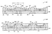
- FIG. 1is a schematic side cross-sectional view of the microelectronic devices after attaching a plurality of radiation responsive dies to a support member.
- FIG. 2is a schematic side cross-sectional view of the microelectronic devices after wire-bonding the radiation responsive dies to the support member and forming a barrier on the support member.
- FIG. 3Ais a schematic side cross-sectional view of the microelectronic devices after attaching a plurality of radiation transmissive windows to the barrier.
- FIG. 3Bis a schematic top plan view of the microelectronic devices of FIG. 3A .
- FIG. 4is a schematic side cross-sectional view of a plurality of microelectronic devices in accordance with another embodiment of the invention.
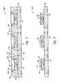
- FIGS. 5 and 6illustrate various stages in a method of packaging a plurality of microelectronic devices in accordance with another embodiment of the invention.
- FIG. 5is a schematic side cross-sectional view of a plurality of microelectronic devices after attaching a plurality of radiation responsive dies to a support member.
- FIG. 6is a schematic side cross-sectional view of the microelectronic devices after wire-bonding the dies to the support member and forming a barrier on the support member.
- FIGS. 7 and 8illustrate various stages in a method of packaging a plurality of microelectronic devices in accordance with another embodiment of the invention.
- FIG. 7is a schematic side cross-sectional view of the microelectronic devices after attaching and wire-bonding a plurality of radiation responsive dies to a support member.
- FIG. 8is a schematic side cross-sectional view of the microelectronic devices after forming a barrier.
- microelectronic devicesand methods of packaging microelectronic devices. Many specific details of several embodiments are described below with reference to microelectronic devices having radiation responsive dies to provide a thorough understanding of such embodiments.
- radiation responsiveis used throughout to encompass devices sensitive to various wavelengths of light and/or other forms of radiation, including, but not limited to, charged coupled devices (CCD), complementary metal-oxide semiconductor (CMOS) image sensors, EPROM's, and photodiodes, as well as light-emitting devices including semiconductor lasers and light-emitting diodes.
- CCDcharged coupled devices
- CMOScomplementary metal-oxide semiconductor
- EPROM'sand photodiodes
- photodiodesas well as light-emitting devices including semiconductor lasers and light-emitting diodes.
- the present inventioncan be practiced using other types of microelectronic devices and/or microelectromechanical devices. Those of ordinary skill in the art will understand that the invention may have additional embodiments, or that the invention may be
- a methodincludes placing a plurality of singulated radiation responsive dies on a support member, electrically connecting circuitry of the radiation responsive dies to contacts of the support member, and forming a barrier on the support member between adjacent radiation responsive dies without an adhesive attaching the barrier to the support member.
- the barrieris formed on the support member after electrically connecting the circuitry of the dies to the contacts of the support member.
- forming the barrierincludes dispensing a flowable material onto the support member.
- the methodcan further include attaching a radiation transmissive window over an active area of a corresponding die. The window can be attached to the barrier with or without an adhesive. Alternatively, the window can be placed on the active area on the corresponding die before the barrier is formed.
- electrically connecting the circuitry of the dies to the contacts of the support memberincludes wire-bonding the dies to the support member.
- a methodin another embodiment, includes providing a plurality of singulated radiation responsive dies, coupling the individual radiation responsive dies to a support member, wire-bonding the radiation responsive dies to the support member, forming a barrier between adjacent radiation responsive dies that encapsulates at least a portion of wire-bonds on adjacent dies, and attaching a plurality of radiation transmissive windows to the barrier and/or the corresponding dies.
- the diesinclude an active area responsive to radiation.
- forming the barrierincludes encapsulating a portion of the radiation responsive dies.
- a plurality of microelectronic devicesinclude a support member, a plurality of radiation responsive dies attached to the support member, a plurality of wire-bonds electrically coupling the radiation responsive dies to the support member, a barrier attached to the support member without an adhesive at a location between the radiation responsive dies, and a plurality of radiation transmissive windows attached to the barrier.
- the radiation responsive dieshave an active area, and the windows cover corresponding active areas. The windows can be attached to the corresponding active areas or spaced apart from the dies by a gap.
- the barrierincludes barrier portions that at least partially encapsulate the wire-bonds of corresponding pairs of adjacent radiation responsive dies. In one aspect of this embodiment, the barrier encapsulates a portion of the radiation responsive dies.
- FIGS. 1–3illustrate various stages in a method of packaging a plurality of microelectronic devices 100 (identified individually as 100 a–c ) in accordance with one embodiment of the invention.
- FIG. 1is a schematic side cross-sectional view of the microelectronic devices 100 including a plurality of radiation responsive dies 110 (identified individually as 110 a–c ) and a support member 160 carrying the dies 110 .
- the radiation responsive dies 110 a–care arranged in a desired array on the support member 160 .
- the radiation responsive die 110 aincludes a first side 112 and a second side 114 opposite the first side 112 .
- the second side 114is generally attached securely to the support member 160 .
- the die 110 acan be attached to the support member 160 with an adhesive film, an epoxy, or another suitable material.
- the die 110 afurther includes a plurality of bond-pads 118 on the first side 112 , an active area 120 on the first side 112 , and an integrated circuit 116 (shown schematically) electrically coupled to the active area 120 and the bond-pads 118 .
- the dies 110 b and 110 ccan have the same structure as the die 110 a , but in some embodiments, the dies 110 a–c can have different features to perform different functions.
- the support member 160can be a lead frame or a substrate such as a printed circuit board to carry the radiation responsive dies 110 .
- the support member 160includes a first side 162 having a plurality of contacts 166 and a second side 164 having a plurality of pads 168 .
- the contacts 166can be arranged in arrays for attachment to the corresponding bond-pads 118 on the dies 110
- the pads 168can be arranged in arrays for attachment to a plurality of electrical couplers (e.g., solder balls).
- the support member 160further includes a plurality of traces 167 that electrically couple the contacts 166 to the corresponding pads 168 .
- FIG. 2is a schematic side cross-sectional view of the microelectronic devices 100 after wire-bonding the radiation responsive dies 110 to the support member 160 and forming a barrier 130 (portions of which are identified individually as 130 a–d ) on the support member 160 .
- a plurality of wire-bonds 122are formed to electrically couple the dies 110 to the support member 160 .
- the wire-bonds 122include a proximal portion 123 coupled to the bond-pads 118 of the dies 110 and a distal portion 124 coupled to the contacts 166 of the support member 160 .
- the integrated circuit 116 of each die 110can be electrically coupled to corresponding pads 168 .
- the barrier 130is formed on the support member 160 to protect the dies 110 from the external environment and to provide a support for a plurality of radiation transmissive windows ( FIG. 3 ).
- the barrier 130can be a flowable material that is dispensed onto the support member 160 through a needle or another suitable process. Suitable materials include epoxy and other similar materials, such as those made by Ablestik Laboratories of Rancho Dominguez, Calif., and Henkel Loctite Corporation of Rocky Hill, Conn.
- the barrier 130can be formed on the support member 160 by screen printing, molding, stenciling, or other processes. The barrier material can be selected so that the barrier 130 bonds to the support member 160 without the use of an adhesive. In other embodiments, the barrier 130 can be attached to the support member 160 with an adhesive.
- the barrier portions 130 a–dhave a width W 1 less than a distance D 1 between the active areas 120 of adjacent dies 110 so that the barrier 130 does not cover the active areas 120 . More specifically, in the illustrated embodiment, the barrier 130 covers and encapsulates the distal portion 124 of the wire-bonds 122 . In other embodiments, such as those described below with reference to FIGS. 4 , 6 , and 8 , the barrier 130 also partially covers a portion of the dies 110 and the proximal portion 123 of the wire-bonds 122 . In the illustrated embodiment, the barrier portions 130 a–d have a height H 1 greater than a height H 2 of the wire-bonds 122 to support the windows ( FIG. 3 ) over the wire-bonds 122 . In other embodiments, such as those described below with reference to FIGS. 7 and 8 , the height H 1 of the barrier portions 130 a–d can be less than or equal to the height H 2 of the wire-bonds 122 .
- FIG. 3Ais a schematic side cross-sectional view of the microelectronic devices 100 after attaching a plurality of radiation transmissive windows 140 (identified individually as 140 a–c ) to the barrier 130
- FIG. 3Bis a schematic top plan view of the microelectronic devices 100 .
- the windows 140are attached between corresponding barrier portions 130 to enclose corresponding radiation responsive dies 110 .
- a first window 140 aincludes a first edge 142 a attached to a first barrier portion 130 a , a second edge 142 b attached to a second barrier portion 130 b , a third edge 142 c attached to a fifth barrier portion 130 e , and a fourth edge 142 d attached to a sixth barrier portion 130 f .
- the windows 140therefore extend over the active area 120 of the corresponding dies 110 .
- the windows 140are made of a transmissive material such as glass to permit light and/or other electromagnetic radiation to pass through.
- the windows 140can be attached to the barrier 130 by exerting a force F ( FIG. 3A ) to move the edges 142 a–d of the windows 140 into the flowable barrier material.
- the windows 140can be attached to the barrier 130 with an adhesive.
- Each window 140is oriented generally parallel to the corresponding die 110 so that a gap G ( FIG. 3A ) between the window 140 and the active area 120 is generally consistent across the first side 112 of the die 110 .
- the gap Gcan be greater than or equal to 10 microns; alternatively, in other embodiments, such as those described below with reference to FIGS. 5 and 6 , the gap G can be less than 10 microns.
- the microelectronic devices 100can be hermetically sealed and/or the devices 100 can include a sealant between the edges 142 a–d of the windows 140 and the barrier 130 .
- a single unitary windowcan be attached to the barrier portions 130 a–d and cover several of the dies 110 .
- the barrier 130can be cured to harden the material and thereby secure the windows 140 over the dies 110 .
- a plurality of electrical couplers 150can be deposited or formed on corresponding pads 168 of the support member 160 so that the microelectronic devices 100 can be attached to external devices.
- the barrier 130 and the support member 160can be cut along lines A 1 —A 1 by scribing, sawing, or another suitable process to singulate the microelectronic devices 100 .
- One feature of the microelectronic devices 100 of the illustrated embodimentis that the barrier 130 encapsulates the distal portion 124 of the wire-bonds 122 .
- An advantage of this featureis that the size of the microelectronic devices 100 is reduced because the barrier portions 130 a–d are positioned closer to the respective dies 110 .
- the microelectronic devices 100have a width W 2 1.2 times greater than a width W 3 of the dies 110 .
- the barrier portionsare attached outside of the distal portion of the wire-bonds and do not encapsulate a portion of the wire-bonds.
- microelectronic devicesare larger than the microelectronic devices 100 of the illustrated embodiment.
- Larger microelectronic deviceshave larger footprints and therefore use more space on printed circuit boards or other substrates in cell phones, PDAs, computers, and other products.
- FIG. 4is a schematic side cross-sectional view of a plurality of microelectronic devices 200 in accordance with another embodiment of the invention.
- the microelectronic devices 200can be generally similar to the microelectronic devices 100 described above with reference to FIGS. 1–3 .
- the microelectronic devices 200include a plurality of radiation responsive dies 110 attached and wire-bonded to a support member 160 . After the dies 110 are attached and wire-bonded to the support member 160 , a barrier 230 is formed between the dies 110 .
- the barrier 230encapsulates the wire-bonds 122 and covers a portion of the dies 110 , but it does not cover the active area 120 of the dies 110 .
- the active areas 120can accordingly receive electromagnetic radiation without interference or obstruction.
- the barrier 230may not completely encapsulate the wire-bonds 122 .
- the barrier 230may encapsulate the distal portion 124 of the wire-bonds 122 and cover a portion of the dies 110 , but may not encapsulate the proximal portion 123 of the wire-bonds 122 .
- a plurality of radiation transmissive windows 240are attached to the barrier 230 over the active area 120 of corresponding dies 110 .
- an adhesive 248bonds first and second edges 242 a–b of the windows 240 to the barrier portions 230 .
- the adhesive 248can be a UV- or thermo-curable epoxy or other suitable material.
- the windows 240can be attached to the barrier 230 without an adhesive 248 , which eliminates a step in the manufacturing process.
- the barrier 230can be cured before and/or after the windows 240 are attached. For example, in one embodiment, the barrier 230 is partially cured to a B-stage or tacky state before the windows 240 are attached and then fully cured after attachment. In other embodiments, the barrier 230 may be cured only after the windows 240 are attached;
- FIGS. 5 and 6illustrate various stages in a method for packaging a plurality of microelectronic devices 300 in accordance with another embodiment of the invention.
- FIG. 5is a schematic side cross-sectional view of a plurality of radiation responsive dies 110 attached to a support member 160 .
- a plurality of radiation transmissive windows 340are placed on the active area 120 of corresponding dies 110 .
- the windows 340are placed on the die 1110 without an adhesive attaching the windows 340 and the first side 112 of the dies 110 .
- an adhesivecan attach the windows 340 to the corresponding dies 110 .
- an adhesivecan be disposed between the windows 340 and the first side 112 of the dies 110 such that the adhesive circumscribes the active area 120 .
- the adhesivecan be disposed between the windows 340 and the dies 110 across the active area 120 .
- the adhesivecan be an optical grade material with a high transparency and a uniform mass density to allow maximum light transmission.
- the adhesivecan also be a highly pure material to minimize contamination and thereby reduce or eliminate the loss of images and/or light scattering.
- the pixels in the active area 120are approximately 3 microns or smaller and the adhesive has an index of refraction of approximately 1.4 or less.
- FIG. 6is a schematic side cross-sectional view of the microelectronic devices 300 after wire-bonding the dies 110 to the support member 160 and forming a barrier 330 on the support member 160 .
- the windows 340After the windows 340 have been placed on the first side 112 of the dies 110 , the dies 110 are wire-bonded to the support member 160 . Alternatively, the windows 340 can be placed on the dies 110 before wire-bonding.
- the barrier 330is formed on the support member 160 between the dies 110 . In the illustrated embodiment, the barrier portions 330 extend between the windows 340 of adjacent dies 110 .
- FIGS. 7 and 8illustrate various stages in a method of packaging a plurality of microelectronic devices 400 in accordance with another embodiment of the invention.
- FIG. 7is a schematic side cross-sectional view of the microelectronic devices 400 after attaching and wire-bonding a plurality of radiation responsive dies 110 to a support member 160 .
- a plurality of radiation transmissive windows 440are placed on the wire-bonds 122 . More specifically, the windows 440 include a first portion 443 supported by corresponding first wire-bonds 122 a and a second portion 444 supported by corresponding second wire-bonds 122 b .
- an adhesive 448is disposed between the windows 440 and the dies 110 .
- the adhesive 448can be similar to the adhesive described above with reference to FIG. 5 .
- the adhesive 448can be dispensed onto a bottom surface 446 of the windows 440 and/or the first side 112 of the dies 110 before the windows 440 are placed onto the wire-bonds 122 .
- the microelectronic devices 400may not include an adhesive, or the adhesive 448 can be arranged so that it circumscribes the active area 120 on the dies 110 and forms a chamber between the windows 440 and the dies 110 .
- FIG. 8is a schematic side cross-sectional view of the microelectronic devices 400 after forming a barrier 430 .
- the barrier 430is formed on the support member 160 between the dies 110 . Portions of the barrier 430 can wick into the gap between the windows 440 and the dies 110 such that the barrier 430 encapsulates the wire-bonds 122 . In other embodiments, the barrier 430 may not completely encapsulate the wire-bonds 122 .
- the barrier 430can be formed on the support member 160 before the windows 440 are placed on the wire-bonds 122 . In any of these embodiments, the barrier 430 can be subsequently cured to secure the windows 440 over the active area 120 of the dies 110 .
Landscapes
- Engineering & Computer Science (AREA)
- Computer Hardware Design (AREA)
- Microelectronics & Electronic Packaging (AREA)
- Power Engineering (AREA)
- Solid State Image Pick-Up Elements (AREA)
- Light Receiving Elements (AREA)
- Encapsulation Of And Coatings For Semiconductor Or Solid State Devices (AREA)
Abstract
Description
This application is a continuation of U.S. application Ser. No. 10/665,912, entitled “MICROELECTRONIC DEVICES AND METHODS FOR PACKAGING MICROELECTRONIC DEVICES” filed Sep. 18, 2003, now U.S. Pat. No. 6,934,065, which is incorporated herein by reference in its entirety.
The present invention is related to microelectronic devices and methods for packaging microelectronic devices. In particular, the present invention is directed to microelectronic devices that include radiation responsive dies.
Microelectronic devices are used in cell phones, pagers, personal digital assistants, computers, and many other products. A die-level packaged microelectronic device can include a microelectronic die, an interposer substrate or lead frame attached to the die, and a molded casing around the die. The microelectronic die generally has an integrated circuit and a plurality of bond-pads coupled to the integrated circuit. The bond-pads are coupled to terminals on the interposer substrate or lead frame. The interposer substrate can also include ball-pads coupled to the terminals by traces in a dielectric material. An array of solder balls is configured so that each solder ball contacts a corresponding ball-pad to define a “ball-grid” array. Packaged microelectronic devices with ball-grid arrays are generally higher grade packages that have lower profiles and higher pin counts than conventional chip packages that use a lead frame.
Packaged microelectronic devices are typically made by (a) forming a plurality of dies on a semiconductor wafer, (b) cutting the wafer to singulate the dies, (c) attaching individual dies to an individual interposer substrate, (d) wire-bonding the bond-pads to the terminals of the interposer substrate, and (e) encapsulating the dies with a molding compound. It is time consuming and expensive to mount individual dies to individual interposer substrates. Also, as the demand for higher pin counts and smaller packages increases, it becomes more difficult to (a) form robust wire-bonds that can withstand the forces involved in molding processes and (b) accurately form other components of die-level packaged devices. Therefore, packaging processes have become a significant factor in producing semiconductor and other microelectronic devices.
Another process for packaging microelectronic devices is wafer-level packaging. In wafer-level packaging, a plurality of microelectronic dies are formed on a wafer and then a redistribution layer is formed on top of the dies. The redistribution layer has a dielectric layer, a plurality of ball-pad arrays on the dielectric layer, and traces coupled to individual ball-pads of the ball-pad arrays. Each ball-pad array is arranged over a corresponding microelectronic die, and the ball-pads in each array are coupled to corresponding bond-pads on the die by the traces in the redistribution layer. After forming the redistribution layer on the wafer, a stenciling machine deposits discrete blocks of solder paste onto the ball-pads of the redistribution layer. The solder paste is then reflowed to form solder balls or solder bumps on the ball-pads. After formation of the solder balls on the ball-pads, the wafer can be cut to singulate the dies. Microelectronic devices packaged at the wafer level can have high pin counts in a small area, but they are not as robust as devices packaged at the die level.
Electronic products require packaged microelectronic devices to have an extremely high density of components in a very limited space. For example, the space available for memory devices, processors, displays, and other microelectronic components is quite limited in cell phones, PDAs, portable computers, and many other products. As such, there is a strong drive to reduce the height of the packaged microelectronic device and the surface area or “footprint” of the microelectronic device on a printed circuit board. Reducing the size of the microelectronic device is difficult because high-performance microelectronic devices generally have more bond-pads, which result in larger ball-grid arrays and thus larger footprints.
Image sensor dies present additional packaging problems. Image sensor dies include an active area that is responsive to light or other electromagnetic radiation. In packaging, it is important to form a cover that protects the active area without obstructing or distorting the passage of light or other electromagnetic radiation to the active area. One existing method for packaging an image sensor die includes placing the die in a recess of a ceramic substrate and attaching a glass window to the substrate over the active area. The window is hermetically sealed to the substrate to enclose the image sensor die. A vacuum pump typically removes air from the gap between the image sensor die and the glass window. An inert gas can then be injected into the gap between the image sensor die and the glass window.
U.S. Pat. No. 6,266,197 discloses another existing method for packaging image sensor dies by attaching and wire-bonding an array of image sensor dies to a carrier substrate. Next, a molded window array is placed over the image sensor dies. The molded window array includes sidewalls that are attached to the carrier substrate between the wire-bonds of adjacent dies and windows that extend between the sidewalls over corresponding dies. The substrate and the attached window array are then cut to form a plurality of individual image sensor packages.
One drawback of packaging image sensor dies in accordance with the above-mentioned methods is that the packaged image sensor dies are relatively bulky and, accordingly, use more space on a circuit board or other external device.
A. Overview
The following description is directed toward microelectronic devices and methods of packaging microelectronic devices. Many specific details of several embodiments are described below with reference to microelectronic devices having radiation responsive dies to provide a thorough understanding of such embodiments. The term “radiation responsive” is used throughout to encompass devices sensitive to various wavelengths of light and/or other forms of radiation, including, but not limited to, charged coupled devices (CCD), complementary metal-oxide semiconductor (CMOS) image sensors, EPROM's, and photodiodes, as well as light-emitting devices including semiconductor lasers and light-emitting diodes. The present invention, however, can be practiced using other types of microelectronic devices and/or microelectromechanical devices. Those of ordinary skill in the art will understand that the invention may have additional embodiments, or that the invention may be practiced without several of the details described below.
Several aspects of the invention are directed to methods of packaging microelectronic devices. In one embodiment, a method includes placing a plurality of singulated radiation responsive dies on a support member, electrically connecting circuitry of the radiation responsive dies to contacts of the support member, and forming a barrier on the support member between adjacent radiation responsive dies without an adhesive attaching the barrier to the support member. The barrier is formed on the support member after electrically connecting the circuitry of the dies to the contacts of the support member. In one aspect of this embodiment, forming the barrier includes dispensing a flowable material onto the support member. The method can further include attaching a radiation transmissive window over an active area of a corresponding die. The window can be attached to the barrier with or without an adhesive. Alternatively, the window can be placed on the active area on the corresponding die before the barrier is formed. In another aspect of this embodiment, electrically connecting the circuitry of the dies to the contacts of the support member includes wire-bonding the dies to the support member.
In another embodiment, a method includes providing a plurality of singulated radiation responsive dies, coupling the individual radiation responsive dies to a support member, wire-bonding the radiation responsive dies to the support member, forming a barrier between adjacent radiation responsive dies that encapsulates at least a portion of wire-bonds on adjacent dies, and attaching a plurality of radiation transmissive windows to the barrier and/or the corresponding dies. The dies include an active area responsive to radiation. In one aspect of this embodiment, forming the barrier includes encapsulating a portion of the radiation responsive dies.
Another aspect of the invention is directed to microelectronic devices. In one embodiment, a plurality of microelectronic devices include a support member, a plurality of radiation responsive dies attached to the support member, a plurality of wire-bonds electrically coupling the radiation responsive dies to the support member, a barrier attached to the support member without an adhesive at a location between the radiation responsive dies, and a plurality of radiation transmissive windows attached to the barrier. The radiation responsive dies have an active area, and the windows cover corresponding active areas. The windows can be attached to the corresponding active areas or spaced apart from the dies by a gap. The barrier includes barrier portions that at least partially encapsulate the wire-bonds of corresponding pairs of adjacent radiation responsive dies. In one aspect of this embodiment, the barrier encapsulates a portion of the radiation responsive dies.
B. Embodiments of Methods for Packaging Microelectronic Devices
Thesupport member 160 can be a lead frame or a substrate such as a printed circuit board to carry the radiation responsive dies110. In the illustrated embodiment, thesupport member 160 includes afirst side 162 having a plurality ofcontacts 166 and asecond side 164 having a plurality ofpads 168. Thecontacts 166 can be arranged in arrays for attachment to the corresponding bond-pads 118 on the dies110, and thepads 168 can be arranged in arrays for attachment to a plurality of electrical couplers (e.g., solder balls). Thesupport member 160 further includes a plurality oftraces 167 that electrically couple thecontacts 166 to thecorresponding pads 168.
After wire-bonding, thebarrier 130 is formed on thesupport member 160 to protect the dies110 from the external environment and to provide a support for a plurality of radiation transmissive windows (FIG. 3 ). Thebarrier 130 can be a flowable material that is dispensed onto thesupport member 160 through a needle or another suitable process. Suitable materials include epoxy and other similar materials, such as those made by Ablestik Laboratories of Rancho Dominguez, Calif., and Henkel Loctite Corporation of Rocky Hill, Conn. In other embodiments, thebarrier 130 can be formed on thesupport member 160 by screen printing, molding, stenciling, or other processes. The barrier material can be selected so that thebarrier 130 bonds to thesupport member 160 without the use of an adhesive. In other embodiments, thebarrier 130 can be attached to thesupport member 160 with an adhesive.
Thebarrier portions 130a–dhave a width W1less than a distance D1between theactive areas 120 of adjacent dies110 so that thebarrier 130 does not cover theactive areas 120. More specifically, in the illustrated embodiment, thebarrier 130 covers and encapsulates thedistal portion 124 of the wire-bonds 122. In other embodiments, such as those described below with reference toFIGS. 4 ,6, and8, thebarrier 130 also partially covers a portion of the dies110 and theproximal portion 123 of the wire-bonds 122. In the illustrated embodiment, thebarrier portions 130a–dhave a height H1greater than a height H2of the wire-bonds 122 to support the windows (FIG. 3 ) over the wire-bonds 122. In other embodiments, such as those described below with reference toFIGS. 7 and 8 , the height H1of thebarrier portions 130a–dcan be less than or equal to the height H2of the wire-bonds 122.
The windows140 can be attached to thebarrier 130 by exerting a force F (FIG. 3A ) to move the edges142a–dof the windows140 into the flowable barrier material. In other embodiments, such as the embodiment described below with reference toFIG. 4 , the windows140 can be attached to thebarrier 130 with an adhesive. Each window140 is oriented generally parallel to the corresponding die110 so that a gap G (FIG. 3A ) between the window140 and theactive area 120 is generally consistent across thefirst side 112 of thedie 110. In one embodiment, the gap G can be greater than or equal to 10 microns; alternatively, in other embodiments, such as those described below with reference toFIGS. 5 and 6 , the gap G can be less than 10 microns. In additional embodiments, themicroelectronic devices 100 can be hermetically sealed and/or thedevices 100 can include a sealant between the edges142a–dof the windows140 and thebarrier 130. In other embodiments, a single unitary window can be attached to thebarrier portions 130a–dand cover several of the dies110.
After attaching the windows140 to thebarrier 130, thebarrier 130 can be cured to harden the material and thereby secure the windows140 over the dies110. Moreover, in the illustrated embodiment, a plurality ofelectrical couplers 150 can be deposited or formed oncorresponding pads 168 of thesupport member 160 so that themicroelectronic devices 100 can be attached to external devices. After curing thebarrier 130 and forming theelectrical couplers 150, thebarrier 130 and thesupport member 160 can be cut along lines A1—A1by scribing, sawing, or another suitable process to singulate themicroelectronic devices 100.
One feature of themicroelectronic devices 100 of the illustrated embodiment is that thebarrier 130 encapsulates thedistal portion 124 of the wire-bonds 122. An advantage of this feature is that the size of themicroelectronic devices 100 is reduced because thebarrier portions 130a–dare positioned closer to the respective dies110. For example, in the illustrated embodiment, themicroelectronic devices 100 have a width W21.2 times greater than a width W3of the dies110. In contrast, in prior art microelectronic devices, the barrier portions are attached outside of the distal portion of the wire-bonds and do not encapsulate a portion of the wire-bonds. Consequently, the prior art microelectronic devices are larger than themicroelectronic devices 100 of the illustrated embodiment. Larger microelectronic devices have larger footprints and therefore use more space on printed circuit boards or other substrates in cell phones, PDAs, computers, and other products.
C. Other Embodiments of Methods for Packaging Microelectronic Devices
After forming thebarrier 230, a plurality of radiationtransmissive windows 240 are attached to thebarrier 230 over theactive area 120 of corresponding dies110. In the illustrated embodiment, an adhesive248 bonds first andsecond edges 242a–bof thewindows 240 to thebarrier portions 230. The adhesive248 can be a UV- or thermo-curable epoxy or other suitable material. In other embodiments, such as the embodiment described above with reference toFIGS. 1–3 , thewindows 240 can be attached to thebarrier 230 without an adhesive248, which eliminates a step in the manufacturing process. Thebarrier 230 can be cured before and/or after thewindows 240 are attached. For example, in one embodiment, thebarrier 230 is partially cured to a B-stage or tacky state before thewindows 240 are attached and then fully cured after attachment. In other embodiments, thebarrier 230 may be cured only after thewindows 240 are attached;
In any of these embodiments, the adhesive can be an optical grade material with a high transparency and a uniform mass density to allow maximum light transmission. The adhesive can also be a highly pure material to minimize contamination and thereby reduce or eliminate the loss of images and/or light scattering. In one such embodiment, the pixels in theactive area 120 are approximately 3 microns or smaller and the adhesive has an index of refraction of approximately 1.4 or less.
From the foregoing, it will be appreciated that specific embodiments of the invention have been described herein for purposes of illustration, but that various modifications may be made without deviating from the spirit and scope of the invention. Accordingly, the invention is not limited, except as by the appended claims.
Claims (25)
1. A method of manufacturing a plurality of microelectronic imaging units, the method comprising:
attaching a plurality of singulated imaging dies to a support member, the individual imaging dies comprising an image sensor, an integrated circuit operably coupled to the image sensor, and a plurality of external contacts operably coupled to the integrated circuit;
wire-bonding the external contacts of the imaging dies to corresponding terminals on the support member;
building a footing on the support member between adjacent imaging dies such that the footing encapsulates a distal portion of the individual wire-bonds proximate to the terminals; and
coupling covers over at least a portion of the footing so that the covers are positioned over the image sensors.
2. The method ofclaim 1 wherein building the footing on the support member comprises depositing a flowable material onto the support member.
3. The method ofclaim 1 wherein building the footing on the support member comprises constructing the footing on the support member such that the footing contacts at least one end of the individual imaging dies.
4. A method of manufacturing a plurality of microelectronic imaging units, the method comprising:
placing a plurality of singulated imaging dies on a support member, the individual imaging dies comprising an image sensor, an integrated circuit operably coupled to the image sensor, and a plurality of external contacts operably coupled to the integrated circuit; electrically connecting the external contacts of the imaging dies to corresponding terminals on the support member;
depositing a flowable material onto the support member to form a support surface between adjacent imaging dies after placing the singulated imaging dies on the support member; and
attaching at least one cover over at least a portion of the support surface with an adhesive so that the cover is positioned over a corresponding image sensor.
5. The method ofclaim 4 wherein depositing the flowable material onto the support member comprises dispensing the flowable material such that the material contacts at least one end of the individual imaging dies.
6. The method ofclaim 4 wherein:
electrically connecting the external contacts to the terminals comprises wire-bonding the external contacts to the terminals; and
depositing the flowable material onto the support member comprises encapsulating a distal portion of the individual wire-bonds proximate to the terminals.
7. A plurality of microelectronic imaging units, comprising: a support member having a plurality of terminal arrays;
a plurality of imaging dies attached to the support member, the individual imaging dies comprising an image sensor, an integrated circuit operably coupled to the image sensor, and a plurality of external contacts operably coupled to the integrated circuit and electrically coupled to corresponding terminals on the support member;
a footing on the support member between adjacent imaging dies and contacting a portion of the individual imaging dies; and
a plurality of covers attached over at least a portion of the footing and positioned over corresponding image sensors.
8. The microelectronic imaging units ofclaim 7 wherein the footing comprises a flowable material.
9. The microelectronic imaging units ofclaim 7 , further comprising a plurality of wire-bonds having a proximal end coupled to one of the external contacts and a distal end coupled to a corresponding terminal, wherein the footing encapsulates the distal end of the individual wire-bonds.
10. The microelectronic imaging units ofclaim 7 , further comprising an adhesive between the individual covers and the footing.
11. A plurality of microelectronic imaging units, comprising:
a support member having a plurality of terminal arrays;
a plurality of imaging dies attached to the support member, the individual imaging dies comprising an image sensor, an integrated circuit operably coupled to the image sensor, and a plurality of external contacts operably coupled to the integrated circuit;
a plurality of wire-bonds having a proximal portion coupled to one of the external contacts and a distal portion coupled to a corresponding terminal;
a footing on the support member encapsulating the distal portion of the individual wire-bonds;
a plurality of covers positioned over corresponding image sensors; and
an adhesive attaching the covers to the footing and/or corresponding imaging dies.
12. The microelectronic imaging units ofclaim 11 wherein the footing comprises a flowable material.
13. The microelectronic imaging units ofclaim 11 wherein the footing contacts a portion of the individual imaging dies.
14. A plurality of microelectronic imaging units, comprising: a support member;
a plurality of singulated imaging dies attached to the support member, the individual imaging dies comprising an image sensor, an integrated circuit operably coupled to the image sensor, and a plurality of external contacts operably coupled to the integrated circuit;
a fill material between adjacent imaging dies, the fill material at least partially encapsulating the imaging dies; and
a plurality of covers supported by at least a portion of the fill material and positioned over associated image sensors.
15. The imaging units ofclaim 14 , further comprising discrete portions of an adhesive attaching the covers to the corresponding dies, the individual portions of the adhesive being disposed between the associated image sensor and the cover.
16. The imaging units ofclaim 14 , further comprising discrete portions of an adhesive attaching the covers to the corresponding dies, the individual portions of the adhesive being disposed inboard the external contacts.
17. The imaging units ofclaim 14 wherein the individual covers are inboard the external contacts.
18. The imaging units ofclaim 14 , further comprising a barrier on the support member between adjacent imaging dies.
19. A plurality of microelectronic imaging units, comprising:
a support member having a plurality of terminal arrays;
a plurality of imaging dies including a first side, a second side attached to the support member, an image sensor on the first side, an integrated circuit operably coupled to the image sensor, and a plurality of external contacts operably coupled to the integrated circuit;
a plurality of covers positioned over associated image sensors;
a plurality of wire-bonds electrically connecting the external contacts on the dies to corresponding terminals on the support member; and
a barrier on the support member between adjacent imaging dies, at least a portion of the barrier supporting at least one of the plurality of covers.
20. The imaging units ofclaim 19 , further comprising discrete portions of an adhesive attaching the covers to the corresponding dies, the individual portions of the adhesive being disposed between the associated image sensor and the cover.
21. A method of manufacturing a plurality of microelectronic imaging units, the method comprising:
providing a plurality of singulated imaging dies, the individual imaging dies comprising an image sensor, an integrated circuit operably coupled to the image sensor, and a plurality of external contacts operably coupled to the integrated circuit;
coupling the singulated imaging dies to a support member;
electrically connecting the external contacts of the imaging dies to corresponding terminals on the support member;
depositing a flowable material onto the support member to form a base between adjacent imaging dies such that the base contacts at least one end of the individual imaging dies; and
attaching at least one cover over at least a portion of the base with the cover over at least one image sensor.
22. The method ofclaim 21 wherein attaching at least one cover to the base comprises coupling a single cover over several image sensors.
23. The method ofclaim 21 wherein attaching at least one cover to the base comprises coupling a plurality of covers over corresponding image sensors.
24. The method ofclaim 21 wherein attaching at least one cover comprises dispensing an adhesive onto the cover and/or the base.
25. The method ofclaim 21 wherein:
electrically connecting the external contacts to the terminals comprises wire-bonding the external contacts to the terminals; and
depositing the flowable material onto the support member comprises encapsulating a distal portion of the individual wire-bonds proximate to the terminals.
Priority Applications (1)
| Application Number | Priority Date | Filing Date | Title |
|---|---|---|---|
| US11/187,105US7321455B2 (en) | 2003-09-18 | 2005-07-22 | Microelectronic devices and methods for packaging microelectronic devices |
Applications Claiming Priority (2)
| Application Number | Priority Date | Filing Date | Title |
|---|---|---|---|
| US10/665,912US6934065B2 (en) | 2003-09-18 | 2003-09-18 | Microelectronic devices and methods for packaging microelectronic devices |
| US11/187,105US7321455B2 (en) | 2003-09-18 | 2005-07-22 | Microelectronic devices and methods for packaging microelectronic devices |
Related Parent Applications (1)
| Application Number | Title | Priority Date | Filing Date |
|---|---|---|---|
| US10/665,912ContinuationUS6934065B2 (en) | 2003-09-18 | 2003-09-18 | Microelectronic devices and methods for packaging microelectronic devices |
Publications (2)
| Publication Number | Publication Date |
|---|---|
| US20050255628A1 US20050255628A1 (en) | 2005-11-17 |
| US7321455B2true US7321455B2 (en) | 2008-01-22 |
Family
ID=34312973
Family Applications (2)
| Application Number | Title | Priority Date | Filing Date |
|---|---|---|---|
| US10/665,912Expired - LifetimeUS6934065B2 (en) | 2003-09-18 | 2003-09-18 | Microelectronic devices and methods for packaging microelectronic devices |
| US11/187,105Expired - LifetimeUS7321455B2 (en) | 2003-09-18 | 2005-07-22 | Microelectronic devices and methods for packaging microelectronic devices |
Family Applications Before (1)
| Application Number | Title | Priority Date | Filing Date |
|---|---|---|---|
| US10/665,912Expired - LifetimeUS6934065B2 (en) | 2003-09-18 | 2003-09-18 | Microelectronic devices and methods for packaging microelectronic devices |
Country Status (1)
| Country | Link |
|---|---|
| US (2) | US6934065B2 (en) |
Cited By (8)
| Publication number | Priority date | Publication date | Assignee | Title |
|---|---|---|---|---|
| US20060072147A1 (en)* | 2004-10-06 | 2006-04-06 | Kabushiki Kaisha Toshiba | System and method for compressing and rotating image data |
| US20060216850A1 (en)* | 2004-08-10 | 2006-09-28 | Street Bret K | Microelectronic imaging units and methods of manufacturing microelectronic imaging units |
| US20080150164A1 (en)* | 2006-12-20 | 2008-06-26 | Phoenix Precision Technology Corporation | Carrier structure embedded with semiconductor chips and method for manufacturing the same |
| US20080290438A1 (en)* | 2007-05-23 | 2008-11-27 | Visera Technologies Company Limited | Image sensing devices and methods for fabricating the same |
| US20090273094A1 (en)* | 2008-05-02 | 2009-11-05 | Jong-Woo Ha | Integrated circuit package on package system |
| US20100244272A1 (en)* | 2008-06-10 | 2010-09-30 | Micron Technology, Inc. | Packaged microelectronic devices and methods for manufacturing packaged microelectronic devices |
| US20110298077A1 (en)* | 2003-09-17 | 2011-12-08 | Round Rock Research, Llc | Methods of fabrication of package assemblies for optically interactive electronic devices and package assemblies therefor |
| US20130249042A1 (en)* | 2012-03-20 | 2013-09-26 | Chipmos Technologies Inc. | Structure of stacking chips and method for manufacturing the same |
Families Citing this family (74)
| Publication number | Priority date | Publication date | Assignee | Title |
|---|---|---|---|---|
| US6934065B2 (en)* | 2003-09-18 | 2005-08-23 | Micron Technology, Inc. | Microelectronic devices and methods for packaging microelectronic devices |
| US7583862B2 (en)* | 2003-11-26 | 2009-09-01 | Aptina Imaging Corporation | Packaged microelectronic imagers and methods of packaging microelectronic imagers |
| US7253397B2 (en)* | 2004-02-23 | 2007-08-07 | Micron Technology, Inc. | Packaged microelectronic imagers and methods of packaging microelectronic imagers |
| US7253957B2 (en)* | 2004-05-13 | 2007-08-07 | Micron Technology, Inc. | Integrated optics units and methods of manufacturing integrated optics units for use with microelectronic imagers |
| US8092734B2 (en)* | 2004-05-13 | 2012-01-10 | Aptina Imaging Corporation | Covers for microelectronic imagers and methods for wafer-level packaging of microelectronics imagers |
| US20050266602A1 (en)* | 2004-05-28 | 2005-12-01 | Intersil Americas, Inc. | Encapsulated chip and method of fabrication thereof |
| US20050266592A1 (en)* | 2004-05-28 | 2005-12-01 | Intersil Americas, Inc. | Method of fabricating an encapsulated chip and chip produced thereby |
| US20050275750A1 (en) | 2004-06-09 | 2005-12-15 | Salman Akram | Wafer-level packaged microelectronic imagers and processes for wafer-level packaging |
| US7498647B2 (en) | 2004-06-10 | 2009-03-03 | Micron Technology, Inc. | Packaged microelectronic imagers and methods of packaging microelectronic imagers |
| US7199439B2 (en)* | 2004-06-14 | 2007-04-03 | Micron Technology, Inc. | Microelectronic imagers and methods of packaging microelectronic imagers |
| US7262405B2 (en)* | 2004-06-14 | 2007-08-28 | Micron Technology, Inc. | Prefabricated housings for microelectronic imagers |
| US7294897B2 (en)* | 2004-06-29 | 2007-11-13 | Micron Technology, Inc. | Packaged microelectronic imagers and methods of packaging microelectronic imagers |
| US7232754B2 (en) | 2004-06-29 | 2007-06-19 | Micron Technology, Inc. | Microelectronic devices and methods for forming interconnects in microelectronic devices |
| US7416913B2 (en)* | 2004-07-16 | 2008-08-26 | Micron Technology, Inc. | Methods of manufacturing microelectronic imaging units with discrete standoffs |
| US7189954B2 (en)* | 2004-07-19 | 2007-03-13 | Micron Technology, Inc. | Microelectronic imagers with optical devices and methods of manufacturing such microelectronic imagers |
| US7402453B2 (en)* | 2004-07-28 | 2008-07-22 | Micron Technology, Inc. | Microelectronic imaging units and methods of manufacturing microelectronic imaging units |
| US7397066B2 (en)* | 2004-08-19 | 2008-07-08 | Micron Technology, Inc. | Microelectronic imagers with curved image sensors and methods for manufacturing microelectronic imagers |
| US7223626B2 (en)* | 2004-08-19 | 2007-05-29 | Micron Technology, Inc. | Spacers for packaged microelectronic imagers and methods of making and using spacers for wafer-level packaging of imagers |
| US7425499B2 (en) | 2004-08-24 | 2008-09-16 | Micron Technology, Inc. | Methods for forming interconnects in vias and microelectronic workpieces including such interconnects |
| US7429494B2 (en)* | 2004-08-24 | 2008-09-30 | Micron Technology, Inc. | Microelectronic imagers with optical devices having integral reference features and methods for manufacturing such microelectronic imagers |
| US7115961B2 (en)* | 2004-08-24 | 2006-10-03 | Micron Technology, Inc. | Packaged microelectronic imaging devices and methods of packaging microelectronic imaging devices |
| US7276393B2 (en)* | 2004-08-26 | 2007-10-02 | Micron Technology, Inc. | Microelectronic imaging units and methods of manufacturing microelectronic imaging units |
| US7511262B2 (en)* | 2004-08-30 | 2009-03-31 | Micron Technology, Inc. | Optical device and assembly for use with imaging dies, and wafer-label imager assembly |
| US20070148807A1 (en)* | 2005-08-22 | 2007-06-28 | Salman Akram | Microelectronic imagers with integrated optical devices and methods for manufacturing such microelectronic imagers |
| US7646075B2 (en)* | 2004-08-31 | 2010-01-12 | Micron Technology, Inc. | Microelectronic imagers having front side contacts |
| US7300857B2 (en) | 2004-09-02 | 2007-11-27 | Micron Technology, Inc. | Through-wafer interconnects for photoimager and memory wafers |
| US20060102974A1 (en)* | 2004-11-12 | 2006-05-18 | Chen Neng C | Contact image capturing structure |
| US20060131709A1 (en)* | 2004-12-21 | 2006-06-22 | Caron Michael R | Semiconductor die positioning system and a method of bonding a semiconductor die to a substrate |
| US7271482B2 (en)* | 2004-12-30 | 2007-09-18 | Micron Technology, Inc. | Methods for forming interconnects in microelectronic workpieces and microelectronic workpieces formed using such methods |
| KR101138944B1 (en)* | 2005-01-26 | 2012-04-25 | 서울옵토디바이스주식회사 | Light emitting device having a plurality of light emitting cells connected in series and method of fabricating the same |
| US7214919B2 (en)* | 2005-02-08 | 2007-05-08 | Micron Technology, Inc. | Microelectronic imaging units and methods of manufacturing microelectronic imaging units |
| US7303931B2 (en)* | 2005-02-10 | 2007-12-04 | Micron Technology, Inc. | Microfeature workpieces having microlenses and methods of forming microlenses on microfeature workpieces |
| US20060177999A1 (en)* | 2005-02-10 | 2006-08-10 | Micron Technology, Inc. | Microelectronic workpieces and methods for forming interconnects in microelectronic workpieces |
| US7190039B2 (en)* | 2005-02-18 | 2007-03-13 | Micron Technology, Inc. | Microelectronic imagers with shaped image sensors and methods for manufacturing microelectronic imagers |
| US20060197201A1 (en)* | 2005-02-23 | 2006-09-07 | Hsin Chung H | Image sensor structure |
| EP1861880B1 (en)* | 2005-03-25 | 2012-06-20 | FUJIFILM Corporation | Method of manufacturing solid state imaging device |
| US7329942B2 (en)* | 2005-05-18 | 2008-02-12 | Ching-Fu Tsou | Array-type modularized light-emitting diode structure and a method for packaging the structure |
| CN1873992A (en)* | 2005-06-03 | 2006-12-06 | 鸿富锦精密工业(深圳)有限公司 | Package of image sensor, and packaging procedure |
| CN1885908B (en)* | 2005-06-24 | 2010-04-28 | 鸿富锦精密工业(深圳)有限公司 | Photography module |
| US7795134B2 (en)* | 2005-06-28 | 2010-09-14 | Micron Technology, Inc. | Conductive interconnect structures and formation methods using supercritical fluids |
| US20060290001A1 (en)* | 2005-06-28 | 2006-12-28 | Micron Technology, Inc. | Interconnect vias and associated methods of formation |
| US20070045800A1 (en)* | 2005-08-19 | 2007-03-01 | Brian King | Opto-coupler with high reverse breakdown voltage and high isolation potential |
| US7288757B2 (en)* | 2005-09-01 | 2007-10-30 | Micron Technology, Inc. | Microelectronic imaging devices and associated methods for attaching transmissive elements |
| US7622377B2 (en) | 2005-09-01 | 2009-11-24 | Micron Technology, Inc. | Microfeature workpiece substrates having through-substrate vias, and associated methods of formation |
| US7262134B2 (en)* | 2005-09-01 | 2007-08-28 | Micron Technology, Inc. | Microfeature workpieces and methods for forming interconnects in microfeature workpieces |
| JP2007188909A (en)* | 2005-12-14 | 2007-07-26 | Fujifilm Corp | Solid-state imaging device and manufacturing method thereof |
| US20070182841A1 (en)* | 2006-02-07 | 2007-08-09 | Donnie Drake | Image sensing microelectronic device with glass tilt control features, and various methods of making same |
| US7498646B2 (en)* | 2006-07-19 | 2009-03-03 | Advanced Chip Engineering Technology Inc. | Structure of image sensor module and a method for manufacturing of wafer level package |
| JP4463793B2 (en)* | 2006-10-10 | 2010-05-19 | 浜松ホトニクス株式会社 | Photodetector |
| CN101174643A (en) | 2006-11-03 | 2008-05-07 | 鸿富锦精密工业(深圳)有限公司 | Image sensor package and image sensor module for its application |
| JP2009081346A (en)* | 2007-09-27 | 2009-04-16 | Panasonic Corp | Optical device and manufacturing method thereof |
| JP2009099680A (en)* | 2007-10-15 | 2009-05-07 | Panasonic Corp | Optical device and manufacturing method thereof |
| US8258015B2 (en)* | 2008-02-22 | 2012-09-04 | Stats Chippac Ltd. | Integrated circuit package system with penetrable film adhesive |
| US8304869B2 (en)* | 2008-08-01 | 2012-11-06 | Stats Chippac Ltd. | Fan-in interposer on lead frame for an integrated circuit package on package system |
| US7776640B2 (en)* | 2008-09-26 | 2010-08-17 | Tong Hsing Electronic Industries Ltd. | Image sensing device and packaging method thereof |
| MY149251A (en)* | 2008-10-23 | 2013-07-31 | Carsem M Sdn Bhd | Wafer-level package using stud bump coated with solder |
| US20100194465A1 (en)* | 2009-02-02 | 2010-08-05 | Ali Salih | Temperature compensated current source and method therefor |
| DE102010034565A1 (en)* | 2010-08-17 | 2012-02-23 | Osram Opto Semiconductors Gmbh | Method for producing at least one optoelectronic semiconductor component |
| US8076181B1 (en)* | 2010-10-22 | 2011-12-13 | Linear Technology Corporation | Lead plating technique for singulated IC packages |
| US9086553B2 (en)* | 2011-06-27 | 2015-07-21 | Avago Technologies General Ip (Singapore) Pte. Ltd. | Optical communications device having electrical bond pads that are protected by a protective coating, and a method for applying the protective coating |
| KR102055840B1 (en) | 2014-02-20 | 2019-12-17 | 삼성전자 주식회사 | Image sensor package |
| US9527723B2 (en) | 2014-03-13 | 2016-12-27 | STATS ChipPAC Pte. Ltd. | Semiconductor device and method of forming microelectromechanical systems (MEMS) package |
| US10447900B2 (en)* | 2015-08-06 | 2019-10-15 | Apple Inc. | Camera module design with lead frame and plastic moulding |
| KR102335306B1 (en)* | 2016-03-12 | 2021-12-03 | 닝보 써니 오포테크 코., 엘티디. | Array Imaging Module and Molded Photensitive Assembly and Manufacturing Method Thereof for Electronic Device |
| CN107591420B (en)* | 2016-07-06 | 2020-02-18 | 胜丽国际股份有限公司 | Sensor Package Structure |
| TWI618156B (en) | 2016-08-05 | 2018-03-11 | 矽品精密工業股份有限公司 | Electronic package and method for fabricating the same |
| TWI697129B (en) | 2016-08-30 | 2020-06-21 | 原相科技股份有限公司 | Far infrared sensor apparatus having multiple sensing element arrays inside single package |
| US9722098B1 (en) | 2016-10-18 | 2017-08-01 | Ase Electronics (M) Sdn Bhd | Semiconductor device package and method of manufacturing the same |
| US9960197B1 (en)* | 2017-01-13 | 2018-05-01 | Semiconductor Components Industries, Llc | Molded image sensor chip scale packages and related methods |
| CN109411486B (en)* | 2017-08-16 | 2020-12-08 | 胜丽国际股份有限公司 | Sensor Package Structure |
| TWI672786B (en)* | 2017-12-28 | 2019-09-21 | 英屬開曼群島商鳳凰先驅股份有限公司 | Electronic package and method of manufacture |
| US11600754B2 (en)* | 2018-11-29 | 2023-03-07 | Lumileds Llc | Light-emitting device and method of packaging the same |
| JP2020129656A (en)* | 2019-02-08 | 2020-08-27 | 旭化成エレクトロニクス株式会社 | Optical device and manufacturing method of optical device |
| TWI883430B (en)* | 2023-04-27 | 2025-05-11 | 業泓科技股份有限公司 | Method for manufacturing an image sensor module |
Citations (103)
| Publication number | Priority date | Publication date | Assignee | Title |
|---|---|---|---|---|
| US3345134A (en) | 1962-04-21 | 1967-10-03 | Knapsack Ag | Process and apparatus for the manufacture of titanium nitride |
| JPS59101882A (en) | 1982-12-03 | 1984-06-12 | Nec Corp | Optical semiconductor device |
| JPS59191388A (en) | 1983-04-14 | 1984-10-30 | Victor Co Of Japan Ltd | semiconductor equipment |
| US4534100A (en) | 1982-06-28 | 1985-08-13 | The United States Of America As Represented By The Secretary Of The Air Force | Electrical method of making conductive paths in silicon |
| US4906314A (en) | 1988-12-30 | 1990-03-06 | Micron Technology, Inc. | Process for simultaneously applying precut swatches of precured polyimide film to each semiconductor die on a wafer |
| WO1990005424A1 (en) | 1988-10-31 | 1990-05-17 | Reimar Lenz | Opto-electronic colour-image sensor |
| US5130783A (en) | 1991-03-04 | 1992-07-14 | Texas Instruments Incorporated | Flexible film semiconductor package |
| US5302778A (en)* | 1992-08-28 | 1994-04-12 | Eastman Kodak Company | Semiconductor insulation for optical devices |
| US5371397A (en) | 1992-10-09 | 1994-12-06 | Mitsubishi Denki Kabushiki Kaisha | Solid-state imaging array including focusing elements |
| US5424573A (en) | 1992-03-04 | 1995-06-13 | Hitachi, Ltd. | Semiconductor package having optical interconnection access |
| US5435887A (en) | 1993-11-03 | 1995-07-25 | Massachusetts Institute Of Technology | Methods for the fabrication of microstructure arrays |
| JPH07263607A (en) | 1994-03-17 | 1995-10-13 | Sumitomo Kinzoku Ceramics:Kk | Semiconductor package with j-lead and bending method of lead frame |
| US5505804A (en) | 1993-12-24 | 1996-04-09 | Sharp Kabushiki Kaisha | Method of producing a condenser lens substrate |
| US5593913A (en) | 1993-09-28 | 1997-01-14 | Sharp Kabushiki Kaisha | Method of manufacturing solid state imaging device having high sensitivity and exhibiting high degree of light utilization |
| US5605783A (en) | 1995-01-06 | 1997-02-25 | Eastman Kodak Company | Pattern transfer techniques for fabrication of lenslet arrays for solid state imagers |
| US5672519A (en) | 1994-02-23 | 1997-09-30 | Lg Semicon Co., Ltd. | Method of fabricating solid state image sensing elements |
| US5694246A (en) | 1994-01-03 | 1997-12-02 | Omron Corporation | Method of manufacturing lens array |
| US5708293A (en) | 1996-01-05 | 1998-01-13 | Matsushita Electronics Corporation | Lead frame and method of mounting semiconductor chip |
| US5771158A (en) | 1995-09-21 | 1998-06-23 | Mitsubishi Denki Kabushiki Kaisha | Printed circuit board, printed circuit board used for flat panel display drive circuit, and flat panel display device |
| US5776824A (en) | 1995-12-22 | 1998-07-07 | Micron Technology, Inc. | Method for producing laminated film/metal structures for known good die ("KG") applications |
| US5811799A (en) | 1997-07-31 | 1998-09-22 | Wu; Liang-Chung | Image sensor package having a wall with a sealed cover |
| US5821532A (en) | 1997-06-16 | 1998-10-13 | Eastman Kodak Company | Imager package substrate |
| US5857963A (en) | 1996-07-17 | 1999-01-12 | Welch Allyn, Inc. | Tab imager assembly for use in an endoscope |
| US5861654A (en) | 1995-11-28 | 1999-01-19 | Eastman Kodak Company | Image sensor assembly |
| US5877040A (en) | 1995-08-10 | 1999-03-02 | Lg Semicon Co., Ltd. | Method of making charge-coupled device with microlens |
| US5897338A (en) | 1996-06-11 | 1999-04-27 | European Semiconductor Assembly (Eurasem) B.V. | Method for encapsulating an integrated semi-conductor circuit |
| US5914488A (en) | 1996-03-05 | 1999-06-22 | Mitsubishi Denki Kabushiki Kaisha | Infrared detector |
| US5977535A (en) | 1992-09-30 | 1999-11-02 | Lsi Logic Corporation | Light sensing device having an array of photosensitive elements coincident with an array of lens formed on an optically transmissive material |
| US5998862A (en) | 1993-03-26 | 1999-12-07 | Sony Corporation | Air-packed CCD images package and a mold for manufacturing thereof |
| US6080291A (en) | 1998-07-10 | 2000-06-27 | Semitool, Inc. | Apparatus for electrochemically processing a workpiece including an electrical contact assembly having a seal member |
| US6104086A (en) | 1997-05-20 | 2000-08-15 | Nec Corporation | Semiconductor device having lead terminals bent in J-shape |
| US6114240A (en) | 1997-12-18 | 2000-09-05 | Micron Technology, Inc. | Method for fabricating semiconductor components using focused laser beam |
| US6143588A (en) | 1997-09-09 | 2000-11-07 | Amkor Technology, Inc. | Method of making an integrated circuit package employing a transparent encapsulant |
| JP2001077496A (en) | 1999-09-06 | 2001-03-23 | Ngk Insulators Ltd | Substrate for printed circuit and its manufacture |
| US6236046B1 (en) | 1997-10-28 | 2001-05-22 | Matsushita Electric Works, Ltd. | Infrared sensor |
| US6259083B1 (en) | 1997-08-13 | 2001-07-10 | Sony Corporation | Solid state imaging device and manufacturing method thereof |
| US6266197B1 (en) | 1999-12-08 | 2001-07-24 | Amkor Technology, Inc. | Molded window array for image sensor packages |
| US6274927B1 (en) | 1999-06-03 | 2001-08-14 | Amkor Technology, Inc. | Plastic package for an optical integrated circuit device and method of making |
| US6285064B1 (en) | 2000-03-28 | 2001-09-04 | Omnivision Technologies, Inc. | Chip scale packaging technique for optical image sensing integrated circuits |
| EP1157967A2 (en) | 2000-05-22 | 2001-11-28 | Lucent Technologies Inc. | Packaging micromechanical devices |
| US20020006687A1 (en) | 2000-05-23 | 2002-01-17 | Lam Ken M. | Integrated IC chip package for electronic image sensor die |
| US6351027B1 (en) | 2000-02-29 | 2002-02-26 | Agilent Technologies, Inc. | Chip-mounted enclosure |
| US6368899B1 (en)* | 2000-03-08 | 2002-04-09 | Maxwell Electronic Components Group, Inc. | Electronic device packaging |
| US6372548B2 (en) | 1998-06-04 | 2002-04-16 | Matsushita Electric Industrial Co., Ltd. | Method for fabricating a semiconductor package with a semiconductor device attached to a multilayered substrate |
| US6379988B1 (en)* | 2000-05-16 | 2002-04-30 | Sandia Corporation | Pre-release plastic packaging of MEMS and IMEMS devices |
| US20020057468A1 (en) | 2000-11-14 | 2002-05-16 | Masao Segawa | Image pickup apparatus, method thereof, and electric apparatus |
| US6407381B1 (en) | 2000-07-05 | 2002-06-18 | Amkor Technology, Inc. | Wafer scale image sensor package |
| US6411439B2 (en) | 1998-05-19 | 2002-06-25 | Seiko Epson Corporation | Microlens array, a manufacturing method therefor, and a display apparatus using the same |
| US20020089025A1 (en) | 2001-01-05 | 2002-07-11 | Li-Kun Chou | Package structure for image IC |
| US20020096729A1 (en) | 2001-01-24 | 2002-07-25 | Tu Hsiu Wen | Stacked package structure of image sensor |
| US20020113296A1 (en) | 2001-02-03 | 2002-08-22 | Samsung Electronics Co., Ltd. | Wafer level hermetic sealing method |
| US6441453B1 (en)* | 2001-05-09 | 2002-08-27 | Conexant Systems, Inc. | Clear coating for digital and analog imagers |
| WO2002075815A1 (en) | 2001-03-16 | 2002-09-26 | Atmel Grenoble S.A. | Low cost electronic camera made with integrated circuit technology |
| US20020145676A1 (en) | 2001-02-26 | 2002-10-10 | Tetsuya Kuno | Image pickup apparatus |
| US6483652B2 (en) | 2000-08-17 | 2002-11-19 | Sharp Kabushiki Kaisha | Method for producing solid-state imaging device |
| WO2002095796A2 (en) | 2001-05-18 | 2002-11-28 | Stmicroelectronics Sa | Optical semiconductor housing with incorporated lens and shielding |
| US6503780B1 (en) | 2000-07-05 | 2003-01-07 | Amkor Technology, Inc. | Wafer scale image sensor package fabrication method |
| US6531341B1 (en)* | 2000-05-16 | 2003-03-11 | Sandia Corporation | Method of fabricating a microelectronic device package with an integral window |
| US6541762B2 (en) | 2001-08-14 | 2003-04-01 | Samsung Electro-Mechanics Co., Ltd. | Sub chip on board for optical mouse |
| US20030062601A1 (en) | 2001-05-15 | 2003-04-03 | James Harnden | Surface mount package |
| US6560047B2 (en) | 2001-08-29 | 2003-05-06 | Samsung Electro-Mechanics Co., Ltd. | Image module |
| US6566745B1 (en) | 1999-03-29 | 2003-05-20 | Imec Vzw | Image sensor ball grid array package and the fabrication thereof |
| US6603183B1 (en) | 2001-09-04 | 2003-08-05 | Amkor Technology, Inc. | Quick sealing glass-lidded package |
| FR2835654A1 (en) | 2002-02-06 | 2003-08-08 | St Microelectronics Sa | OPTICAL SEMICONDUCTOR PACKAGE WITH COUPLED LENS HOLDER |
| US6617623B2 (en) | 1999-06-15 | 2003-09-09 | Micron Technology, Inc. | Multi-layered gate for a CMOS imager |
| US6661047B2 (en) | 2001-08-30 | 2003-12-09 | Micron Technology, Inc. | CMOS imager and method of formation |
| US6667551B2 (en) | 2000-01-21 | 2003-12-23 | Seiko Epson Corporation | Semiconductor device and manufacturing thereof, including a through-hole with a wider intermediate cavity |
| US6670986B1 (en) | 1998-09-10 | 2003-12-30 | Creo Il. Ltd. | Apparatus for orthogonal movement of a CCD sensor and a method of light sampling therewith |
| US20040012698A1 (en) | 2001-03-05 | 2004-01-22 | Yasuo Suda | Image pickup model and image pickup device |
| US6686588B1 (en) | 2001-01-16 | 2004-02-03 | Amkor Technology, Inc. | Optical module with lens integral holder |
| US20040023469A1 (en) | 2001-03-21 | 2004-02-05 | Canon Kabushiki Kaisha | Semiconductor device and its manufacture method |
| US20040038442A1 (en) | 2002-08-26 | 2004-02-26 | Kinsman Larry D. | Optically interactive device packages and methods of assembly |
| US20040041261A1 (en) | 2002-08-29 | 2004-03-04 | Kinsman Larry D. | Flip-chip image sensor packages and methods of fabrication |
| US6703310B2 (en) | 2001-06-14 | 2004-03-09 | Shinko Electric Industries Co., Ltd. | Semiconductor device and method of production of same |
| US6709898B1 (en)* | 2000-10-04 | 2004-03-23 | Intel Corporation | Die-in-heat spreader microelectronic package |
| US20040082094A1 (en) | 2002-10-25 | 2004-04-29 | Katsumi Yamamoto | Method for making and packaging image sensor die using protective coating |
| US6734419B1 (en) | 2001-06-28 | 2004-05-11 | Amkor Technology, Inc. | Method for forming an image sensor package with vision die in lens housing |
| WO2004054001A2 (en) | 2002-12-09 | 2004-06-24 | Quantum Semiconductor Llc | Cmos image sensor |
| US6759266B1 (en) | 2001-09-04 | 2004-07-06 | Amkor Technology, Inc. | Quick sealing glass-lidded package fabrication method |
| US6774486B2 (en) | 2001-10-10 | 2004-08-10 | Micron Technology, Inc. | Circuit boards containing vias and methods for producing same |
| US6778046B2 (en) | 2001-09-17 | 2004-08-17 | Magfusion Inc. | Latching micro magnetic relay packages and methods of packaging |
| US6791076B2 (en) | 1999-12-08 | 2004-09-14 | Amkor Technology, Inc. | Image sensor package |
| US20040178495A1 (en) | 2003-03-14 | 2004-09-16 | Yean Tay Wuu | Microelectronic devices and methods for packaging microelectronic devices |
| US6794223B2 (en)* | 2000-09-28 | 2004-09-21 | Intel Corporation | Structure and process for reducing die corner and edge stresses in microelectronic packages |
| US6795120B2 (en) | 1996-05-17 | 2004-09-21 | Sony Corporation | Solid-state imaging apparatus and camera using the same |
| US6800943B2 (en) | 2001-04-03 | 2004-10-05 | Matsushita Electric Industrial Co., Ltd. | Solid image pickup device |
| US20040214373A1 (en) | 2003-04-22 | 2004-10-28 | Tongbi Jiang | Packaged microelectronic devices and methods for packaging microelectronic devices |
| US6813154B2 (en) | 2002-12-10 | 2004-11-02 | Motorola, Inc. | Reversible heat sink packaging assembly for an integrated circuit |
| US6825458B1 (en) | 1999-10-30 | 2004-11-30 | Robert Bosch Gmbh | Optoelectronic receiver and method of making an aligned optoelectronic receiver |
| US6828663B2 (en) | 2001-03-07 | 2004-12-07 | Teledyne Technologies Incorporated | Method of packaging a device with a lead frame, and an apparatus formed therefrom |
| US6828674B2 (en) | 2000-04-10 | 2004-12-07 | Analog Devices, Inc. | Hermetically sealed microstructure package |
| US20040245649A1 (en) | 2003-04-16 | 2004-12-09 | Seiko Epson Corporation | Optical device, optical module, semiconductor apparatus and its manufacturing method, and electronic apparatus |
| US6844978B2 (en) | 1997-10-03 | 2005-01-18 | Digital Optics Corp. | Wafer level creation of multiple optical elements |
| US6864172B2 (en) | 2002-06-18 | 2005-03-08 | Sanyo Electric Co., Ltd. | Manufacturing method of semiconductor device |
| US20050052751A1 (en) | 2000-12-27 | 2005-03-10 | Yue Liu | Wafer integration of micro-optics |
| US6882021B2 (en)* | 2003-05-30 | 2005-04-19 | Micron Technology, Inc. | Packaged image sensing microelectronic devices including a lead and methods of packaging image sensing microelectronic devices including a lead |
| US20050104228A1 (en) | 2003-11-13 | 2005-05-19 | Rigg Sidney B. | Microelectronic devices, methods for forming vias in microelectronic devices, and methods for packaging microelectronic devices |
| US20050110889A1 (en) | 2003-11-26 | 2005-05-26 | Tuttle Mark E. | Packaged microelectronic imagers and methods of packaging microelectronic imagers |
| US20050127478A1 (en) | 2003-12-10 | 2005-06-16 | Hiatt William M. | Microelectronic devices and methods for filling vias in microelectronic devices |
| US20050151228A1 (en) | 2003-12-04 | 2005-07-14 | Kazumasa Tanida | Semiconductor chip and manufacturing method for the same, and semiconductor device |
| US6934065B2 (en) | 2003-09-18 | 2005-08-23 | Micron Technology, Inc. | Microelectronic devices and methods for packaging microelectronic devices |
| US20050236708A1 (en) | 2004-04-27 | 2005-10-27 | Farnworth Warren M | Microelectronic imaging devices and methods of packaging microelectronic imaging devices |
| US20050254133A1 (en) | 2004-05-13 | 2005-11-17 | Salman Akram | Integrated optics units and methods of manufacturing integrated optics units for use with microelectronic imagers |
Family Cites Families (2)
| Publication number | Priority date | Publication date | Assignee | Title |
|---|---|---|---|---|
| JP2872051B2 (en)* | 1994-10-04 | 1999-03-17 | カーネル技研株式会社 | Underwater glasses |
| US6901943B2 (en) | 2002-07-05 | 2005-06-07 | Toyoda Gosei Co., Ltd. | Apparatus for inhibiting fuels from flowing out of fuel tanks |
- 2003
- 2003-09-18USUS10/665,912patent/US6934065B2/ennot_activeExpired - Lifetime
- 2005
- 2005-07-22USUS11/187,105patent/US7321455B2/ennot_activeExpired - Lifetime
Patent Citations (107)
| Publication number | Priority date | Publication date | Assignee | Title |
|---|---|---|---|---|
| US3345134A (en) | 1962-04-21 | 1967-10-03 | Knapsack Ag | Process and apparatus for the manufacture of titanium nitride |
| US4534100A (en) | 1982-06-28 | 1985-08-13 | The United States Of America As Represented By The Secretary Of The Air Force | Electrical method of making conductive paths in silicon |
| JPS59101882A (en) | 1982-12-03 | 1984-06-12 | Nec Corp | Optical semiconductor device |
| JPS59191388A (en) | 1983-04-14 | 1984-10-30 | Victor Co Of Japan Ltd | semiconductor equipment |
| WO1990005424A1 (en) | 1988-10-31 | 1990-05-17 | Reimar Lenz | Opto-electronic colour-image sensor |
| US4906314A (en) | 1988-12-30 | 1990-03-06 | Micron Technology, Inc. | Process for simultaneously applying precut swatches of precured polyimide film to each semiconductor die on a wafer |
| US5130783A (en) | 1991-03-04 | 1992-07-14 | Texas Instruments Incorporated | Flexible film semiconductor package |
| US5424573A (en) | 1992-03-04 | 1995-06-13 | Hitachi, Ltd. | Semiconductor package having optical interconnection access |
| US5302778A (en)* | 1992-08-28 | 1994-04-12 | Eastman Kodak Company | Semiconductor insulation for optical devices |
| US5977535A (en) | 1992-09-30 | 1999-11-02 | Lsi Logic Corporation | Light sensing device having an array of photosensitive elements coincident with an array of lens formed on an optically transmissive material |
| US5371397A (en) | 1992-10-09 | 1994-12-06 | Mitsubishi Denki Kabushiki Kaisha | Solid-state imaging array including focusing elements |
| US5998862A (en) | 1993-03-26 | 1999-12-07 | Sony Corporation | Air-packed CCD images package and a mold for manufacturing thereof |
| US5593913A (en) | 1993-09-28 | 1997-01-14 | Sharp Kabushiki Kaisha | Method of manufacturing solid state imaging device having high sensitivity and exhibiting high degree of light utilization |
| US5435887A (en) | 1993-11-03 | 1995-07-25 | Massachusetts Institute Of Technology | Methods for the fabrication of microstructure arrays |
| US5505804A (en) | 1993-12-24 | 1996-04-09 | Sharp Kabushiki Kaisha | Method of producing a condenser lens substrate |
| US5694246A (en) | 1994-01-03 | 1997-12-02 | Omron Corporation | Method of manufacturing lens array |
| US5672519A (en) | 1994-02-23 | 1997-09-30 | Lg Semicon Co., Ltd. | Method of fabricating solid state image sensing elements |
| JPH07263607A (en) | 1994-03-17 | 1995-10-13 | Sumitomo Kinzoku Ceramics:Kk | Semiconductor package with j-lead and bending method of lead frame |
| US5605783A (en) | 1995-01-06 | 1997-02-25 | Eastman Kodak Company | Pattern transfer techniques for fabrication of lenslet arrays for solid state imagers |
| US5877040A (en) | 1995-08-10 | 1999-03-02 | Lg Semicon Co., Ltd. | Method of making charge-coupled device with microlens |
| US5771158A (en) | 1995-09-21 | 1998-06-23 | Mitsubishi Denki Kabushiki Kaisha | Printed circuit board, printed circuit board used for flat panel display drive circuit, and flat panel display device |
| US5861654A (en) | 1995-11-28 | 1999-01-19 | Eastman Kodak Company | Image sensor assembly |
| US5776824A (en) | 1995-12-22 | 1998-07-07 | Micron Technology, Inc. | Method for producing laminated film/metal structures for known good die ("KG") applications |
| US5708293A (en) | 1996-01-05 | 1998-01-13 | Matsushita Electronics Corporation | Lead frame and method of mounting semiconductor chip |
| US5914488A (en) | 1996-03-05 | 1999-06-22 | Mitsubishi Denki Kabushiki Kaisha | Infrared detector |
| US6795120B2 (en) | 1996-05-17 | 2004-09-21 | Sony Corporation | Solid-state imaging apparatus and camera using the same |
| US5897338A (en) | 1996-06-11 | 1999-04-27 | European Semiconductor Assembly (Eurasem) B.V. | Method for encapsulating an integrated semi-conductor circuit |
| US5857963A (en) | 1996-07-17 | 1999-01-12 | Welch Allyn, Inc. | Tab imager assembly for use in an endoscope |
| US6104086A (en) | 1997-05-20 | 2000-08-15 | Nec Corporation | Semiconductor device having lead terminals bent in J-shape |
| US5821532A (en) | 1997-06-16 | 1998-10-13 | Eastman Kodak Company | Imager package substrate |
| EP0886323A2 (en) | 1997-06-16 | 1998-12-23 | Eastman Kodak Company | Imager package substrate |
| US5811799A (en) | 1997-07-31 | 1998-09-22 | Wu; Liang-Chung | Image sensor package having a wall with a sealed cover |
| US6259083B1 (en) | 1997-08-13 | 2001-07-10 | Sony Corporation | Solid state imaging device and manufacturing method thereof |
| US6143588A (en) | 1997-09-09 | 2000-11-07 | Amkor Technology, Inc. | Method of making an integrated circuit package employing a transparent encapsulant |
| US6844978B2 (en) | 1997-10-03 | 2005-01-18 | Digital Optics Corp. | Wafer level creation of multiple optical elements |
| US6236046B1 (en) | 1997-10-28 | 2001-05-22 | Matsushita Electric Works, Ltd. | Infrared sensor |
| US6114240A (en) | 1997-12-18 | 2000-09-05 | Micron Technology, Inc. | Method for fabricating semiconductor components using focused laser beam |
| US6411439B2 (en) | 1998-05-19 | 2002-06-25 | Seiko Epson Corporation | Microlens array, a manufacturing method therefor, and a display apparatus using the same |
| US6372548B2 (en) | 1998-06-04 | 2002-04-16 | Matsushita Electric Industrial Co., Ltd. | Method for fabricating a semiconductor package with a semiconductor device attached to a multilayered substrate |
| US6080291A (en) | 1998-07-10 | 2000-06-27 | Semitool, Inc. | Apparatus for electrochemically processing a workpiece including an electrical contact assembly having a seal member |
| US6670986B1 (en) | 1998-09-10 | 2003-12-30 | Creo Il. Ltd. | Apparatus for orthogonal movement of a CCD sensor and a method of light sampling therewith |
| US6566745B1 (en) | 1999-03-29 | 2003-05-20 | Imec Vzw | Image sensor ball grid array package and the fabrication thereof |
| US6420204B2 (en)* | 1999-06-03 | 2002-07-16 | Amkor Technology, Inc. | Method of making a plastic package for an optical integrated circuit device |
| US6274927B1 (en) | 1999-06-03 | 2001-08-14 | Amkor Technology, Inc. | Plastic package for an optical integrated circuit device and method of making |
| US6617623B2 (en) | 1999-06-15 | 2003-09-09 | Micron Technology, Inc. | Multi-layered gate for a CMOS imager |
| JP2001077496A (en) | 1999-09-06 | 2001-03-23 | Ngk Insulators Ltd | Substrate for printed circuit and its manufacture |
| US6825458B1 (en) | 1999-10-30 | 2004-11-30 | Robert Bosch Gmbh | Optoelectronic receiver and method of making an aligned optoelectronic receiver |
| US6791076B2 (en) | 1999-12-08 | 2004-09-14 | Amkor Technology, Inc. | Image sensor package |
| US6266197B1 (en) | 1999-12-08 | 2001-07-24 | Amkor Technology, Inc. | Molded window array for image sensor packages |
| US6667551B2 (en) | 2000-01-21 | 2003-12-23 | Seiko Epson Corporation | Semiconductor device and manufacturing thereof, including a through-hole with a wider intermediate cavity |
| US6351027B1 (en) | 2000-02-29 | 2002-02-26 | Agilent Technologies, Inc. | Chip-mounted enclosure |
| US6368899B1 (en)* | 2000-03-08 | 2002-04-09 | Maxwell Electronic Components Group, Inc. | Electronic device packaging |
| US6285064B1 (en) | 2000-03-28 | 2001-09-04 | Omnivision Technologies, Inc. | Chip scale packaging technique for optical image sensing integrated circuits |
| US6828674B2 (en) | 2000-04-10 | 2004-12-07 | Analog Devices, Inc. | Hermetically sealed microstructure package |
| US6379988B1 (en)* | 2000-05-16 | 2002-04-30 | Sandia Corporation | Pre-release plastic packaging of MEMS and IMEMS devices |
| US6531341B1 (en)* | 2000-05-16 | 2003-03-11 | Sandia Corporation | Method of fabricating a microelectronic device package with an integral window |
| EP1157967A2 (en) | 2000-05-22 | 2001-11-28 | Lucent Technologies Inc. | Packaging micromechanical devices |
| US20020006687A1 (en) | 2000-05-23 | 2002-01-17 | Lam Ken M. | Integrated IC chip package for electronic image sensor die |
| US6503780B1 (en) | 2000-07-05 | 2003-01-07 | Amkor Technology, Inc. | Wafer scale image sensor package fabrication method |
| US6407381B1 (en) | 2000-07-05 | 2002-06-18 | Amkor Technology, Inc. | Wafer scale image sensor package |
| US6483652B2 (en) | 2000-08-17 | 2002-11-19 | Sharp Kabushiki Kaisha | Method for producing solid-state imaging device |
| US6794223B2 (en)* | 2000-09-28 | 2004-09-21 | Intel Corporation | Structure and process for reducing die corner and edge stresses in microelectronic packages |
| US6709898B1 (en)* | 2000-10-04 | 2004-03-23 | Intel Corporation | Die-in-heat spreader microelectronic package |
| US20020057468A1 (en) | 2000-11-14 | 2002-05-16 | Masao Segawa | Image pickup apparatus, method thereof, and electric apparatus |
| US20050052751A1 (en) | 2000-12-27 | 2005-03-10 | Yue Liu | Wafer integration of micro-optics |
| US20020089025A1 (en) | 2001-01-05 | 2002-07-11 | Li-Kun Chou | Package structure for image IC |
| US6686588B1 (en) | 2001-01-16 | 2004-02-03 | Amkor Technology, Inc. | Optical module with lens integral holder |
| US20020096729A1 (en) | 2001-01-24 | 2002-07-25 | Tu Hsiu Wen | Stacked package structure of image sensor |
| US20020113296A1 (en) | 2001-02-03 | 2002-08-22 | Samsung Electronics Co., Ltd. | Wafer level hermetic sealing method |
| US20020145676A1 (en) | 2001-02-26 | 2002-10-10 | Tetsuya Kuno | Image pickup apparatus |
| US20040012698A1 (en) | 2001-03-05 | 2004-01-22 | Yasuo Suda | Image pickup model and image pickup device |
| US6828663B2 (en) | 2001-03-07 | 2004-12-07 | Teledyne Technologies Incorporated | Method of packaging a device with a lead frame, and an apparatus formed therefrom |
| WO2002075815A1 (en) | 2001-03-16 | 2002-09-26 | Atmel Grenoble S.A. | Low cost electronic camera made with integrated circuit technology |
| US20040023469A1 (en) | 2001-03-21 | 2004-02-05 | Canon Kabushiki Kaisha | Semiconductor device and its manufacture method |
| US6800943B2 (en) | 2001-04-03 | 2004-10-05 | Matsushita Electric Industrial Co., Ltd. | Solid image pickup device |
| US6441453B1 (en)* | 2001-05-09 | 2002-08-27 | Conexant Systems, Inc. | Clear coating for digital and analog imagers |
| US20030062601A1 (en) | 2001-05-15 | 2003-04-03 | James Harnden | Surface mount package |
| WO2002095796A2 (en) | 2001-05-18 | 2002-11-28 | Stmicroelectronics Sa | Optical semiconductor housing with incorporated lens and shielding |
| US6703310B2 (en) | 2001-06-14 | 2004-03-09 | Shinko Electric Industries Co., Ltd. | Semiconductor device and method of production of same |
| US6734419B1 (en) | 2001-06-28 | 2004-05-11 | Amkor Technology, Inc. | Method for forming an image sensor package with vision die in lens housing |
| US6541762B2 (en) | 2001-08-14 | 2003-04-01 | Samsung Electro-Mechanics Co., Ltd. | Sub chip on board for optical mouse |
| US6560047B2 (en) | 2001-08-29 | 2003-05-06 | Samsung Electro-Mechanics Co., Ltd. | Image module |
| US6661047B2 (en) | 2001-08-30 | 2003-12-09 | Micron Technology, Inc. | CMOS imager and method of formation |
| US6603183B1 (en) | 2001-09-04 | 2003-08-05 | Amkor Technology, Inc. | Quick sealing glass-lidded package |
| US6759266B1 (en) | 2001-09-04 | 2004-07-06 | Amkor Technology, Inc. | Quick sealing glass-lidded package fabrication method |
| US6778046B2 (en) | 2001-09-17 | 2004-08-17 | Magfusion Inc. | Latching micro magnetic relay packages and methods of packaging |
| US6797616B2 (en) | 2001-10-10 | 2004-09-28 | Micron Technology, Inc. | Circuit boards containing vias and methods for producing same |
| US6774486B2 (en) | 2001-10-10 | 2004-08-10 | Micron Technology, Inc. | Circuit boards containing vias and methods for producing same |
| FR2835654A1 (en) | 2002-02-06 | 2003-08-08 | St Microelectronics Sa | OPTICAL SEMICONDUCTOR PACKAGE WITH COUPLED LENS HOLDER |
| US6864172B2 (en) | 2002-06-18 | 2005-03-08 | Sanyo Electric Co., Ltd. | Manufacturing method of semiconductor device |
| US20040038442A1 (en) | 2002-08-26 | 2004-02-26 | Kinsman Larry D. | Optically interactive device packages and methods of assembly |
| US20040041261A1 (en) | 2002-08-29 | 2004-03-04 | Kinsman Larry D. | Flip-chip image sensor packages and methods of fabrication |
| US6885107B2 (en) | 2002-08-29 | 2005-04-26 | Micron Technology, Inc. | Flip-chip image sensor packages and methods of fabrication |
| US20040082094A1 (en) | 2002-10-25 | 2004-04-29 | Katsumi Yamamoto | Method for making and packaging image sensor die using protective coating |
| WO2004054001A2 (en) | 2002-12-09 | 2004-06-24 | Quantum Semiconductor Llc | Cmos image sensor |
| US6813154B2 (en) | 2002-12-10 | 2004-11-02 | Motorola, Inc. | Reversible heat sink packaging assembly for an integrated circuit |
| US20040178495A1 (en) | 2003-03-14 | 2004-09-16 | Yean Tay Wuu | Microelectronic devices and methods for packaging microelectronic devices |
| US20040245649A1 (en) | 2003-04-16 | 2004-12-09 | Seiko Epson Corporation | Optical device, optical module, semiconductor apparatus and its manufacturing method, and electronic apparatus |
| US20040214373A1 (en) | 2003-04-22 | 2004-10-28 | Tongbi Jiang | Packaged microelectronic devices and methods for packaging microelectronic devices |
| US6882021B2 (en)* | 2003-05-30 | 2005-04-19 | Micron Technology, Inc. | Packaged image sensing microelectronic devices including a lead and methods of packaging image sensing microelectronic devices including a lead |
| US6934065B2 (en) | 2003-09-18 | 2005-08-23 | Micron Technology, Inc. | Microelectronic devices and methods for packaging microelectronic devices |
| US20050104228A1 (en) | 2003-11-13 | 2005-05-19 | Rigg Sidney B. | Microelectronic devices, methods for forming vias in microelectronic devices, and methods for packaging microelectronic devices |
| US20050110889A1 (en) | 2003-11-26 | 2005-05-26 | Tuttle Mark E. | Packaged microelectronic imagers and methods of packaging microelectronic imagers |
| US20050151228A1 (en) | 2003-12-04 | 2005-07-14 | Kazumasa Tanida | Semiconductor chip and manufacturing method for the same, and semiconductor device |
| US20050127478A1 (en) | 2003-12-10 | 2005-06-16 | Hiatt William M. | Microelectronic devices and methods for filling vias in microelectronic devices |
| US20050236708A1 (en) | 2004-04-27 | 2005-10-27 | Farnworth Warren M | Microelectronic imaging devices and methods of packaging microelectronic imaging devices |
| US20050254133A1 (en) | 2004-05-13 | 2005-11-17 | Salman Akram | Integrated optics units and methods of manufacturing integrated optics units for use with microelectronic imagers |
Non-Patent Citations (72)
| Title |
|---|
| Aachboun, S. and P. Ranson, "Cryogenic etching of deep narrow trenches in silicon," J. Vac. Sci. Technol. A 18(4), Jul./Aug. 2000, pp. 1848-1852. |
| Aachboun, S. and P. Ranson, "Deep anisotropic etching of silicon," J. Vac. Sci. Technol. A 17(4), Jul./Aug. 1999, pp. 2270-2273. |
| Austin, M.D. and S.Y. Chou, "Fabrication of 70 nm channel length polymer organic thin-film transistors using nanoimprint lithography," Applied Physics Letters, vol. 81, No. 23, pp. 4431-4433, Dec. 2, 2002, American Institute of Physics. |
| Blackburn, J.M. et al., "Deposistion of Conformal Copper and Nickel Films from Supercritical Carbon Dioxide," Science, vol. 294, pp. 141-145, Oct. 5, 2001. |
| Brubaker, C. et al., "Ultra-thick Lithography for Advanced Packaging and MEMS," SPIE's 27th Annual International Symposium on Microlithography 2002, Mar. 3-8, 2002, Santa Clara, CA. |
| Cheng, Yu-T. et al., "Vacuum Packaging Technology Using Localized Aluminum/Silicon-to-Glass Bonding," Journal of Microelectromechanical Systems, vol. 11, No. 5, pp. 556-565, Oct. 2002. |
| DuPont Electronic Materials, Data Sheet, Pyralux PC 2000 Flexible Composites, 4 pages, Oct. 1998, <http://www.dupont.com/fcm>. |
| Edmund Industrial Optics, Mounted IR Filters, 1 page, retrieved from the Internet on Jun. 30, 2003, <http://www.edmundoptics.com>. |
| Hamdorf, M. et al., "Surface-rheological measurements on glass forming polymers based on the surface tension driven decay of imprinted corrugation grantings," Journal of Chemical Physics, vol. 112, No. 9, pp. 4262-4270, Mar. 1, 2000, American Institute of Physics. |
| Hirafune, S. et al., "Packaging Technology for Imager Using Through-hole Interconnection in Si Substrate," Proceeding of HDP'04, IEEE, pp. 303-306, Jul. 2004. |
| IBM, Zurich Research Laboraotry, EPON SU-8 photoresist, 1 page, retrieved from the Internet on Jan. 21, 2003, <http://www.zurich.ibm.com/st/mems/su8.html>. |
| Intrinsic Viscosity and Its Relation to Instrinsic Conductivity, 9 pages, retrieved from the Internet on Oct. 30, 2003, <http://www.ciks.cbt.nlst.gov/~garbocz/paper58/node3.html>. |
| King, B. et al., Optomec, Inc., M3D(TM) Technology, Maskless Mesoscale(TM) Materials Deposition, 5 pages, <http://www.optomec.com/downloads/M3D%20White%Paper%20080502.pdf>, retrieved from the Internet on Jun. 17, 2005. |
| Kingpak Technology, Inc. "CMOS Image Sensor Packaging," 1 page, retrieved from the Internet on Aug. 26, 2003, <http://www.kingpak.com/CMOSImager.html>. |
| Kramer, S.J. et al., "Annual Report - Applications of Supercritical Fluid Technology to Semiconductor Device Processing," pp. 1-29, Nov. 2001. |
| Kyocera Corporation, Memory Package, 1 page, retrieved from the Internet on Dec. 3, 2004, <http://global.kyocera.com/prdct/semicon/ic<SUB>-</SUB>pkg/memory<SUB>-</SUB>p.html>. |
| Lin, Tim (Zhigang) and Rick Yoon, "One Package Technique of Exposed MEMS Sensors," pp. 105-108, 2002 International Symposium on Microelectronics, Sep. 2002. |
| Ma, X. et al., "Low Temperature Bonding for Wafer Scale Packaging and Assembly of Micromachined Sensors," Final Report 1998-1999 for MICRO Project 98-144, 3 pages, Department of Electrical & Computer Engineering, University of California, Davis. |
| Micro Chem, Nano SU-8, Negative Tone Photoresist Formulations 50-100, 4 pages, Feb. 2002, <http://www.microchem.com/products/pdf/SU8<SUB>-</SUB>50-100.pdf>. |
| Optomec, Inc., M3D(TM) Technology, Maskless Mesoscale Materials Deposition (M3D), 1 page, <http://www.optomec.com/html/m3d.htm>, retrieved from the Internet on Aug. 15, 2003. |
| Optomec, Inc., M3D(TM), Maskless Mesoscale(TM) Materials Deposition, 2 pages, <http://www.optomec.com/downloads/M3DSheet.pdf>, retrieved from the Internet on Jun. 17, 2005. |
| Photo Vision Systems, Inc., "Advances in Digital Image Sensors," 22 pages, First Annual New York State Conference on Microelectronic Design, Jan. 12, 2002. |
| Shen, X.-J. et al., "Microplastic embossing process: experimental and theoretical characterizations," Sensors and Actuators, A 97-98 (2002) pp. 428-433, Elsevier Science B.V. |
| Tapes II International Tape and Fabrication Company, Electronics and Electrical Tapes, 2 pages, 2003, <http://www.tapes2.com/electronics.htm>. |
| TransChip, 1 page, retrieved from the Internet on Aug. 26, 2003, <http://www.missionventures.com/portfolio/companies/transchip.html>. |
| TransChip, Inc., CMOS vs CCD, 3 pages, retrieved from the Internet on Dec. 14, 2005, <http://www.transchip.com/content.aspx?id=127>. |
| TransChip, Inc., technology, 3 pages, retrieved from the Internet on Dec. 14, 2005, <http://www.transchip.com/content.aspx?id=10>. |
| U.S. Appl. No. 10/785,466, Kirby. |
| U.S. Appl. No. 10/845,304, Jiang et al. |
| U.S. Appl. No. 10/857,948, Boettiger et al. |
| U.S. Appl. No. 10/863,994, Akram et al. |
| U.S. Appl. No. 10/864,974, Kirby et al. |
| U.S. Appl. No. 10/867,352, Farnworth et al. |
| U.S. Appl. No. 10/867,505, Farnworth et al. |
| U.S. Appl. No. 10/879,398, Akram et al. |
| U.S. Appl. No. 10/879,838, Kirby et al. |
| U.S. Appl. No. 10/893,022, filed Jul. 16, 2004, Hall et al. |
| U.S. Appl. No. 10/894,262, Farnworth et al. |
| U.S. Appl. No. 10/901,851, filed Jul. 28, 2004, Derderian et al. |
| U.S. Appl. No. 10/910,491, Bolken et al. |
| U.S. Appl. No. 10/915,180, filed Aug. 10, 2004, Street et al. |
| U.S. Appl. No. 10/919,604, Farnworth et al. |
| U.S. Appl. No. 10/922,177, Oliver et al. |
| U.S. Appl. No. 10/922,192, Farnworth. |
| U.S. Appl. No. 10/925,406, Oliver. |
| U.S. Appl. No. 10/925,501, Oliver. |
| U.S. Appl. No. 10/925,502, Watkins et al. |
| U.S. Appl. No. 10/927,550, filed Aug. 26, 2004, Derderian et al. |
| U.S. Appl. No. 10/927,760, Chong et al. |
| U.S. Appl. No. 10/928,598, Kirby. |
| U.S. Appl. No. 10/932,296, Oliver et al. |
| U.S. Appl. No. 11/027,443, Kirby. |
| U.S. Appl. No. 11/054,692, Boemler. |
| U.S. Appl. No. 11/056,211, Hembree et al. |
| U.S. Appl. No. 11/056,484, Boettiger et al. |
| U.S. Appl. No. 11/061,034, Boettiger. |
| U.S. Appl. No. 11/146,783, Tuttle et al. |
| U.S. Appl. No. 11/169,546, Sulfridge. |
| U.S. Appl. No. 11/169,838, Sulfridge. |
| U.S. Appl. No. 11/177,905, Akram. |
| U.S. Appl. No. 11/209,524, Akram. |
| U.S. Appl. No. 11/217,169, Hiatt et al. |
| U.S. Appl. No. 11/217,877, Oliver et al. |
| U.S. Appl. No. 11/218,126, Farnworth et al. |
| U.S. Appl. No. 11/218,243, Kirby et al. |
| UCI Integrated Nanosystems Research Facility, "Cleaning procedures for glass substrates," 3 pages, Fall 1999. |
| UCI Integrated Nanosystems Research Facility, "Glass Etch Wet Process," 3 pages, Summer 2000. |
| Walker, M.J., "Comparison of Bosch and cryogenic processes for patterning high aspect ratio features in silicon," 11 pages, Proc. SPIE vol. 4407, pp. 89-99, MEMES Design, Fabrication, Characterization, and Packaging, Uwe F. Behringer; Deepak G. Uttamchandani; Eds., Apr. 2001. |
| Xsil, Via Applications, 1 page, <http://www.xsil.com/viaapplications/index.htm>, retrieved from the Internet on Jul. 22, 2003. |
| Xsil, Vias for 3D Packaging, 1 page, <http://www.xsil.com/viaapplications/3dpackaging/index.htm>, retrieved from the Internet on Jul. 22, 2003. |
| Ye, X.R. et al., "Immersion Deposition of Metal Films on Silicon and Germanium Substrates in Supercritical Carbon Dioxide," Chem. Mater. 2003, 15, 83-91. |
| Yoshida, J. "TransChip rolls out a single-chip CMOS imager," 3 pages. EE Times, Jul. 18, 2003. |
Cited By (22)
| Publication number | Priority date | Publication date | Assignee | Title |
|---|---|---|---|---|
| US8624371B2 (en) | 2003-09-17 | 2014-01-07 | Round Rock Research, Llc | Methods of fabrication of package assemblies for optically interactive electronic devices and package assemblies therefor |
| US8426954B2 (en)* | 2003-09-17 | 2013-04-23 | Round Rock Research, Llc | Methods of fabrication of package assemblies for optically interactive electronic devices and package assemblies therefor |
| US20110298077A1 (en)* | 2003-09-17 | 2011-12-08 | Round Rock Research, Llc | Methods of fabrication of package assemblies for optically interactive electronic devices and package assemblies therefor |
| US20060216850A1 (en)* | 2004-08-10 | 2006-09-28 | Street Bret K | Microelectronic imaging units and methods of manufacturing microelectronic imaging units |
| US7498606B2 (en)* | 2004-08-10 | 2009-03-03 | Micron Technology, Inc. | Microelectronic imaging units and methods of manufacturing microelectronic imaging units |
| US7742199B2 (en)* | 2004-10-06 | 2010-06-22 | Kabushiki Kaisha Toshiba | System and method for compressing and rotating image data |
| US20060072147A1 (en)* | 2004-10-06 | 2006-04-06 | Kabushiki Kaisha Toshiba | System and method for compressing and rotating image data |
| US7829987B2 (en)* | 2006-12-20 | 2010-11-09 | Unimicron Technology Corp. | Carrier structure embedded with semiconductor chips and method for manufacturing the same |
| US20080150164A1 (en)* | 2006-12-20 | 2008-06-26 | Phoenix Precision Technology Corporation | Carrier structure embedded with semiconductor chips and method for manufacturing the same |
| US8153458B2 (en) | 2007-05-23 | 2012-04-10 | Visera Technologies Company Limited | Image sensing devices and methods for fabricating the same |
| US20090181490A1 (en)* | 2007-05-23 | 2009-07-16 | Visera Technologies Company Limited | Image sensing devices and methods for fabricating the same |
| US7528420B2 (en)* | 2007-05-23 | 2009-05-05 | Visera Technologies Company Limited | Image sensing devices and methods for fabricating the same |
| US20080290438A1 (en)* | 2007-05-23 | 2008-11-27 | Visera Technologies Company Limited | Image sensing devices and methods for fabricating the same |
| US7968373B2 (en) | 2008-05-02 | 2011-06-28 | Stats Chippac Ltd. | Integrated circuit package on package system |
| US20090273094A1 (en)* | 2008-05-02 | 2009-11-05 | Jong-Woo Ha | Integrated circuit package on package system |
| US8148807B2 (en)* | 2008-06-10 | 2012-04-03 | Micron Technology, Inc. | Packaged microelectronic devices and associated systems |
| US20100244272A1 (en)* | 2008-06-10 | 2010-09-30 | Micron Technology, Inc. | Packaged microelectronic devices and methods for manufacturing packaged microelectronic devices |
| US8940581B2 (en) | 2008-06-10 | 2015-01-27 | Micron Technology, Inc. | Packaged microelectronic devices and methods for manufacturing packaged microelectronic devices |
| US9530748B2 (en) | 2008-06-10 | 2016-12-27 | Micron Technology, Inc. | Packaged microelectronic devices and methods for manufacturing packaged microelectronic devices |
| US10008468B2 (en) | 2008-06-10 | 2018-06-26 | Micron Technology, Inc. | Packaged microelectronic devices and methods for manufacturing packaged microelectronic devices |
| US20130249042A1 (en)* | 2012-03-20 | 2013-09-26 | Chipmos Technologies Inc. | Structure of stacking chips and method for manufacturing the same |
| US8809088B2 (en)* | 2012-03-20 | 2014-08-19 | Chipmos Technologies Inc. | Structure of stacking chips and method for manufacturing the same |
Also Published As
| Publication number | Publication date |
|---|---|
| US20050063033A1 (en) | 2005-03-24 |
| US20050255628A1 (en) | 2005-11-17 |
| US6934065B2 (en) | 2005-08-23 |
Similar Documents
| Publication | Publication Date | Title |
|---|---|---|
| US7321455B2 (en) | Microelectronic devices and methods for packaging microelectronic devices | |
| US6882021B2 (en) | Packaged image sensing microelectronic devices including a lead and methods of packaging image sensing microelectronic devices including a lead | |
| US6900531B2 (en) | Image sensor device | |
| US7498606B2 (en) | Microelectronic imaging units and methods of manufacturing microelectronic imaging units | |
| US8092734B2 (en) | Covers for microelectronic imagers and methods for wafer-level packaging of microelectronics imagers | |
| US7247934B2 (en) | Multi-chip semiconductor package | |
| US8704380B2 (en) | Methods for wafer-level packaging of microfeature devices and microfeature devices formed using such methods | |
| US8378502B2 (en) | Integrated circuit package system with image sensor system | |
| US8012776B2 (en) | Methods of manufacturing imaging device packages | |
| US5923958A (en) | Method for semiconductor chip packaging | |
| US7745897B2 (en) | Methods for packaging an image sensor and a packaged image sensor | |
| US20090045476A1 (en) | Image sensor package and method for forming the same | |
| US7405100B1 (en) | Packaging of a semiconductor device with a non-opaque cover | |
| US20090256222A1 (en) | Packaging method of image sensing device | |
| US20090224344A1 (en) | Packaging method of image sensing device | |
| US6873024B1 (en) | Apparatus and method for wafer level packaging of optical imaging semiconductor devices | |
| US8003426B2 (en) | Method for manufacturing package structure of optical device | |
| US20060256222A1 (en) | CIS Package and Method Thereof | |
| US20060255253A1 (en) | Method for packaging an image sensor die and a package thereof | |
| US20090179290A1 (en) | Encapsulated imager packaging | |
| US20090315130A1 (en) | Solid-state imaging apparatus and method for manufacturing the same | |
| US20250287720A1 (en) | Cavity package | |
| US20240186346A1 (en) | Semiconductor packaging for image sensors | |
| KR100499328B1 (en) | Flip Chip Packaging Method using Dam | |
| CN112151563A (en) | Stacked image sensor package structure and packaging method |
Legal Events
| Date | Code | Title | Description |
|---|---|---|---|
| FEPP | Fee payment procedure | Free format text:PAYOR NUMBER ASSIGNED (ORIGINAL EVENT CODE: ASPN); ENTITY STATUS OF PATENT OWNER: LARGE ENTITY | |
| STCF | Information on status: patent grant | Free format text:PATENTED CASE | |
| CC | Certificate of correction | ||
| FPAY | Fee payment | Year of fee payment:4 | |
| FPAY | Fee payment | Year of fee payment:8 | |
| AS | Assignment | Owner name:APTINA IMAGING CORPORATION, CAYMAN ISLANDS Free format text:ASSIGNMENT OF ASSIGNORS INTEREST;ASSIGNOR:MICRON TECHNOLOGY, INC.;REEL/FRAME:040355/0989 Effective date:20080926 Owner name:MICRON TECHNOLOGY, INC., IDAHO Free format text:ASSIGNMENT OF ASSIGNORS INTEREST;ASSIGNOR:KINSMAN, LARRY D.;REEL/FRAME:040355/0796 Effective date:20030827 | |
| MAFP | Maintenance fee payment | Free format text:PAYMENT OF MAINTENANCE FEE, 12TH YEAR, LARGE ENTITY (ORIGINAL EVENT CODE: M1553); ENTITY STATUS OF PATENT OWNER: LARGE ENTITY Year of fee payment:12 |