US7320692B1 - Tissue closure system - Google Patents
Tissue closure systemDownload PDFInfo
- Publication number
- US7320692B1 US7320692B1US11/158,414US15841405AUS7320692B1US 7320692 B1US7320692 B1US 7320692B1US 15841405 AUS15841405 AUS 15841405AUS 7320692 B1US7320692 B1US 7320692B1
- Authority
- US
- United States
- Prior art keywords
- staple
- housing
- opening
- configuration
- butterfly
- Prior art date
- Legal status (The legal status is an assumption and is not a legal conclusion. Google has not performed a legal analysis and makes no representation as to the accuracy of the status listed.)
- Expired - Fee Related, expires
Links
- 238000000034methodMethods0.000claimsabstractdescription42
- 210000001519tissueAnatomy0.000claimsabstractdescription33
- 210000005003heart tissueAnatomy0.000claimsabstractdescription16
- 208000035478Interatrial communicationDiseases0.000claimsabstractdescription4
- 208000008883Patent Foramen OvaleDiseases0.000claimsabstractdescription4
- 208000013914atrial heart septal defectDiseases0.000claimsabstractdescription4
- 206010003664atrial septal defectDiseases0.000claimsabstractdescription4
- 210000005166vasculatureAnatomy0.000claimsabstractdescription3
- 238000003384imaging methodMethods0.000claimsdescription4
- 230000000149penetrating effectEffects0.000claims3
- 230000007246mechanismEffects0.000abstractdescription20
- 239000012636effectorSubstances0.000description75
- OCDRLZFZBHZTKQ-NMUBGGKPSA-NonetineChemical compoundC[C@@H](O)[C@@]1(O)C[C@@H](C)[C@@](C)(O)C(=O)OC\C2=C\CN(C)CC[C@@H](OC1=O)C2=OOCDRLZFZBHZTKQ-NMUBGGKPSA-N0.000description72
- 210000004204blood vesselAnatomy0.000description41
- 230000033001locomotionEffects0.000description32
- 239000008280bloodSubstances0.000description9
- 210000004369bloodAnatomy0.000description9
- 239000000463materialSubstances0.000description7
- 210000001105femoral arteryAnatomy0.000description6
- 239000010935stainless steelSubstances0.000description4
- 229910001220stainless steelInorganic materials0.000description4
- 230000002792vascularEffects0.000description4
- 230000006835compressionEffects0.000description3
- 238000007906compressionMethods0.000description3
- 238000004519manufacturing processMethods0.000description3
- 239000007787solidSubstances0.000description3
- 238000013459approachMethods0.000description2
- 230000002452interceptive effectEffects0.000description2
- 229910001000nickel titaniumInorganic materials0.000description2
- 239000000126substanceSubstances0.000description2
- 206010053567CoagulopathiesDiseases0.000description1
- 102000008186CollagenHuman genes0.000description1
- 108010035532CollagenProteins0.000description1
- 208000034656ContusionsDiseases0.000description1
- RTAQQCXQSZGOHL-UHFFFAOYSA-NTitaniumChemical compound[Ti]RTAQQCXQSZGOHL-UHFFFAOYSA-N0.000description1
- 208000002223abdominal aortic aneurysmDiseases0.000description1
- 238000002679ablationMethods0.000description1
- 238000002583angiographyMethods0.000description1
- 238000002399angioplastyMethods0.000description1
- 230000010100anticoagulationEffects0.000description1
- 208000007474aortic aneurysmDiseases0.000description1
- 230000001746atrial effectEffects0.000description1
- 238000005452bendingMethods0.000description1
- 230000033228biological regulationEffects0.000description1
- 230000005540biological transmissionEffects0.000description1
- 230000008859changeEffects0.000description1
- 230000035602clottingEffects0.000description1
- 229920001436collagenPolymers0.000description1
- 238000010276constructionMethods0.000description1
- 210000004351coronary vesselAnatomy0.000description1
- 230000007423decreaseEffects0.000description1
- 230000005489elastic deformationEffects0.000description1
- 210000002615epidermisAnatomy0.000description1
- 210000002837heart atriumAnatomy0.000description1
- 230000003993interactionEffects0.000description1
- 238000013152interventional procedureMethods0.000description1
- 229910052751metalInorganic materials0.000description1
- 239000002184metalSubstances0.000description1
- 238000002324minimally invasive surgeryMethods0.000description1
- 239000000203mixtureSubstances0.000description1
- 230000004048modificationEffects0.000description1
- 238000012986modificationMethods0.000description1
- 230000037361pathwayEffects0.000description1
- 230000035515penetrationEffects0.000description1
- 230000002093peripheral effectEffects0.000description1
- 230000008569processEffects0.000description1
- 230000000452restraining effectEffects0.000description1
- 210000003491skinAnatomy0.000description1
- 239000002002slurrySubstances0.000description1
- 238000002560therapeutic procedureMethods0.000description1
- 239000010936titaniumSubstances0.000description1
- 229910052719titaniumInorganic materials0.000description1
- 230000007704transitionEffects0.000description1
Images


Classifications
- A—HUMAN NECESSITIES
- A61—MEDICAL OR VETERINARY SCIENCE; HYGIENE
- A61B—DIAGNOSIS; SURGERY; IDENTIFICATION
- A61B17/00—Surgical instruments, devices or methods
- A61B17/068—Surgical staplers, e.g. containing multiple staples or clamps
- A61B17/0682—Surgical staplers, e.g. containing multiple staples or clamps for applying U-shaped staples or clamps, e.g. without a forming anvil
- A61B17/0684—Surgical staplers, e.g. containing multiple staples or clamps for applying U-shaped staples or clamps, e.g. without a forming anvil having a forming anvil staying above the tissue during stapling
- A—HUMAN NECESSITIES
- A61—MEDICAL OR VETERINARY SCIENCE; HYGIENE
- A61B—DIAGNOSIS; SURGERY; IDENTIFICATION
- A61B17/00—Surgical instruments, devices or methods
- A61B17/0057—Implements for plugging an opening in the wall of a hollow or tubular organ, e.g. for sealing a vessel puncture or closing a cardiac septal defect
- A—HUMAN NECESSITIES
- A61—MEDICAL OR VETERINARY SCIENCE; HYGIENE
- A61B—DIAGNOSIS; SURGERY; IDENTIFICATION
- A61B17/00—Surgical instruments, devices or methods
- A61B17/064—Surgical staples, i.e. penetrating the tissue
- A61B17/0644—Surgical staples, i.e. penetrating the tissue penetrating the tissue, deformable to closed position
- A—HUMAN NECESSITIES
- A61—MEDICAL OR VETERINARY SCIENCE; HYGIENE
- A61B—DIAGNOSIS; SURGERY; IDENTIFICATION
- A61B17/00—Surgical instruments, devices or methods
- A61B17/10—Surgical instruments, devices or methods for applying or removing wound clamps, e.g. containing only one clamp or staple; Wound clamp magazines
- A—HUMAN NECESSITIES
- A61—MEDICAL OR VETERINARY SCIENCE; HYGIENE
- A61B—DIAGNOSIS; SURGERY; IDENTIFICATION
- A61B17/00—Surgical instruments, devices or methods
- A61B17/00234—Surgical instruments, devices or methods for minimally invasive surgery
- A61B2017/00238—Type of minimally invasive operation
- A61B2017/00243—Type of minimally invasive operation cardiac
- A—HUMAN NECESSITIES
- A61—MEDICAL OR VETERINARY SCIENCE; HYGIENE
- A61B—DIAGNOSIS; SURGERY; IDENTIFICATION
- A61B17/00—Surgical instruments, devices or methods
- A61B17/0057—Implements for plugging an opening in the wall of a hollow or tubular organ, e.g. for sealing a vessel puncture or closing a cardiac septal defect
- A61B2017/00637—Implements for plugging an opening in the wall of a hollow or tubular organ, e.g. for sealing a vessel puncture or closing a cardiac septal defect for sealing trocar wounds through abdominal wall
- A—HUMAN NECESSITIES
- A61—MEDICAL OR VETERINARY SCIENCE; HYGIENE
- A61B—DIAGNOSIS; SURGERY; IDENTIFICATION
- A61B17/00—Surgical instruments, devices or methods
- A61B17/0057—Implements for plugging an opening in the wall of a hollow or tubular organ, e.g. for sealing a vessel puncture or closing a cardiac septal defect
- A61B2017/00646—Type of implements
- A61B2017/00668—Type of implements the implement being a tack or a staple
Definitions
- the present inventionrelates generally to a system for closing an opening in a tissue structure.
- aortic aneurysm grafts and/or stentsMillions of people each year undergo catheterization for reasons including stent placement, angioplasty, angiography, atrial ablation, placement of abdominal aortic aneurysm grafts and/or stents, and other interventional cardiologic and vascular procedures.
- catheterizationan opening is made in the wall of the femoral artery, and a sheath is placed in that opening through which a guidewire and one or more tools may be inserted for performing treatment on the patient.
- the opening in the femoral arterymust be closed. Compression is typically used to do so. Anticoagulation therapy is stopped, and manual pressure is applied to the site for up to an hour until clotting seals the access site. The patient then must remain motionless for up to 24 hours, generally with a sandbag or other heavy weight on the site to continue the compression. Many patients find this procedure, and the resultant bruising and pain, to be more unpleasant than the actual interventional procedure that was performed.
- closure devices and techniqueshave been developed in an attempt to facilitate closure of the opening in the femoral artery.
- acceptance of these devices and techniqueshas been limited for several reasons, including complexity of use, complication rates similar to traditional closure, and cost.
- One type of deviceutilizes suture to close the opening.
- Such devicesare typically complex mechanically and consequently are complex to operate. Further, such devices often require an auxiliary knot-pushing tool to be used, further increasing complexity.
- Other devicesare ring-shaped or shaped in a convoluted or tortuous manner, and are complicated and expensive to manufacture.
- Another closure techniqueinvolves inserting a plug or slurry of collagen or other chemical composition into the opening and/or the pathway in the leg between the opening and the skin.
- compression and lengthy bed restare generally still required with chemical closure techniques, just as with traditional closure.
- FIG. 1is a schematic view of a vascular closure system that includes an end effector, a shaft and a handle.
- FIG. 2is a perspective view of the end effector having butterfly members in a first, collapsed configuration.
- FIG. 3 ais a cross-section view of a butterfly member of the end effector along the line A-A in FIG. 2 .
- FIG. 3 bis a cross-section view of a butterfly member of the end effector along the line B-B in FIG. 2 .
- FIG. 4is a perspective cross-section view of the end effector in a first configuration.
- FIG. 5is a side view of the staple of FIG. 4 in a first configuration.
- FIG. 6is a side view of paddles and a finger that are utilized within the end effector.
- FIG. 7is a schematic view of tissue having a catheterization sheath positioned therein.
- FIG. 8is a perspective view of the end effector having butterfly members in a second, expanded configuration.
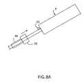
- FIG. 8Ais a schematic view of the handle and shaft of the vascular closure system and their relationship with a sheath.
- FIG. 9is a perspective view of the end effector after the butterfly members have been moved proximally.
- FIG. 10is a perspective cutaway view of the end effector in a second configuration, as the staple is splayed.
- FIG. 10Ais a perspective view of the end effector in a third configuration, after the splayed staple has been shuttled distally.
- FIG. 11is a perspective view of the end effector in a fourth configuration, as the staple is closed.
- FIG. 12is a top view of an embodiment of a staple.
- FIG. 13Ais a side view of the distal end of one exemplary butterfly member.
- FIG. 13Bis a side view of the distal end of a different exemplary butterfly member.
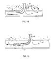
- FIG. 14is a side view of a first step in the operation of the closure system.
- FIG. 15is a side view of a second step in the operation of the closure system.
- FIG. 16is a side view of a third step in the operation of the closure system.
- FIG. 17is a side view of a fourth step in the operation of the closure system.
- FIG. 18is a side view of a fifth step in the operation of the closure system.
- a closure system 2includes an end effector 4 connected to a shaft 6 , which in turn is connected to a handle 8 .
- the end effector 4may be one or more separate components that are connected to the shaft 6 , or may be fabricated integrally with the distal end of the shaft 6 .
- the end effector 4is sized to pass through a standard sheath 48 placed in a passage 53 in tissue 52 for a standard catheterization procedure.
- the end effector 4includes at least one butterfly member 10 .
- Each butterfly member 10acts to register tissue such as the wall of a blood vessel to the end effector 4 , as described in greater detail below.
- At least one butterfly member 10may extend substantially distally from a housing 22 or other component of the end effector 4 . Alternately, at least one butterfly member 10 extends at least partially in a different direction.
- Each butterfly member 10may be configured in any manner that allows it to move from a first, collapsed configuration to a second, expanded configuration, and back to the collapsed configuration.
- at least one butterfly member 10includes a first element 12 , and a second element 14 connected to the distal end of the first element 12 .
- the first element 12is not substantially deformable, and at least part of the second element 14 is deformable to an expanded configuration. Alternately, either or both of the elements 12 , 14 is deformable to an expanded configuration.
- the elements 12 , 14may be shaped and configured in any suitable manner. As one example, referring also to FIGS. 3 a - 3 b , the first element 12 may have a semicircular cross-section or other curved cross-section along at least part of its length. Such a cross section increases the moment of inertia of the first element 12 and thereby increases its stiffness. At least part of the first element 12 may be partially tubular, hollow, or otherwise include an area configured to receive a portion of the second element 14 , or vice versa.
- At least part of the first element 12may be substantially coaxial with the second element 14 .
- the distal end 16 of at least one butterfly member 10may be blunt in order to prevent or minimize any disturbance to the tissue structure into which the butterfly member 10 is inserted.
- the distal end of at least one butterfly member 10may be curved at the junction between the elements 12 , 14 .
- At least one butterfly member 10may have a longitudinal axis in the collapsed configuration that is offset from and substantially parallel to the longitudinal axis of the end effector 4 and/or the shaft 6 .
- the use of the term “axis” in this documentis not limited to use with respect to structures that are cylindrical or radially symmetrical, and the use of the term “axis” in conjunction with a structure does not and cannot limit the shape of that structure.
- at least one butterfly member 10is oriented differently relative to the longitudinal axis of the end effector 4 and/or the shaft 6 .
- the second element 14may include two substantially planar segments 18 longitudinally spaced from one another and connected to one another by a hinge element 20 between them, such that one segment 18 is positioned distal to the other segment.
- the hinge element 20may be a living hinge, such as a narrower area between the two segments 18 that bends to allow movement between the segments 18 .
- the hinge element 20may be any structure or mechanism that allows for relative movement between the segments 18 .
- At least one of the segments 18may be curved or otherwise non-planar.
- One of the planar segments 18may extend to a location at or in proximity to the distal end 16 of the corresponding butterfly member 10 .
- the segments 18may be angled relative to one another when the butterfly member 10 is in the first, collapsed configuration.
- the most-distal segment 18may be angled relative to the longitudinal axis of the corresponding butterfly member 10 such that the distal end of that segment 18 is closer to that longitudinal axis than the proximal end of that segment 18
- the most-proximal segment 18may be angled relative to the longitudinal axis of the corresponding butterfly member 10 such that the proximal end of that segment 18 is closer to that longitudinal axis than the distal end of that segment 18
- the segments 18may be angled differently relative to one another. The angle between the segments 18 allows the hinge 20 to deform or otherwise move upon application of force to the second element 14 , as described in greater detail below.
- the segments 18may be angled relative to one another a greater amount when the butterfly member 10 is in the second, expanded configuration than in the first, collapsed configuration. Alternately, the segments 18 may be substantially parallel to one another and/or lie in substantially the same plane as one another. Referring to FIG. 13A , the segments 18 each may be substantially the same length, such that they form a symmetrical shape upon actuation of the butterfly member 10 . Alternately, referring to FIG. 13B , the segments 18 may differ in length, such that they form a non-symmetrical shape upon actuation of the butterfly member 10 .
- the first element 12may extend into the housing 22 of the end effector 4 through a notch, aperture or other opening.
- the first element 12may instead extend along a groove or other receiving area of the housing 22 , rather than or in addition to extending into the housing 22 .
- the first element 12is movable relative to the housing 22 .
- the first element 12is fixed substantially to the housing 22 .
- the first element 12may extend through the shaft 6 to the handle 8 .
- the proximal end of the first element 12extends substantially proximally from the housing 22 in any suitable amount.
- a proximal portion of the second element 14may extend into a center area 25 of a proximal portion of the first element 12 .
- That center area 25 of the first element 12may be referred to as the lumen of the first element 12 for convenience, even though the first element 12 may be open along part of its perimeter, or may have a cross-section other than circular, at any portion of its length.
- the longitudinal axis of the lumen 25may be substantially coincident with the longitudinal axis of the first element 12 , or may be offset from or otherwise aligned relative to the longitudinal axis of the first element 12 .
- the second element 14may be movable relative to that lumen 25 , such as by sliding substantially along or substantially parallel to the longitudinal axis of the lumen 25 .
- the second element 14does not extend into the lumen 25 of the first element 12 .
- the second element 14does not include a lumen 25 .
- both the first element 12 and the second element 14may be substantially flat, or gently curved.
- the elements 12 , 14may be adjacent to one another, or spaced apart from one another, along at least part of their length, particularly where neither element 12 , 14 includes a lumen 25 .
- At least one of the elements 12 , 14may be configured to move, such as by sliding, relative to at least part of the other element 12 , 14 .
- at least part of the second element 14includes a lumen 25 therein, and a portion of the first element 12 may extend into that lumen 25 .
- the first element 12 and the second element 14may both be parts of an integral whole, shaped to constitute the butterfly member 10 .
- the butterfly member 10may be stamped from a sheet of metal, such as stainless steel. The butterfly member 10 may then be folded, where the first element 12 is on one side of the fold and the second element 14 is on the other side of the fold. At least a portion of each member 12 , 14 may be folded into a semicircular or other shape as viewed longitudinally, before or after the folding.
- Each butterfly member 10may be fabricated from any suitable material.
- at least one butterfly member 10may be fabricated from any material, such as nickel-titanium alloy, that is elastically or superelastically deformable between the first configuration and the second configuration.
- At least one butterfly member 10may be fabricated from any material, such as stainless steel or plastic, that is plastically deformable between the first configuration and the second configuration. At least part of at least one butterfly member 10 may be plastically deformable between the collapsed configuration and the expanded configuration. At least part of the butterfly member 10 may be annealed, such that it can be plastically deformed without fracturing. Both of the elements 12 , 14 may be substantially rigid, such that they are capable of transmitting both compressive and tensile force.
- a staple 24is initially positioned within a space inside the end effector 4 .
- the staple 24is positioned differently within the end effector 4 , or is positioned at the end of the end effector 4 rather than within it.
- the staple 24may be sized and shaped in any suitable manner.
- the staple 24may have a curved M-shape.
- the staple 24may have any other suitable shape.
- the staple 24may have two tines 26 , each extending at least partially in the distal direction.
- the tines 26may be curved, and may each have a shape and radius of curvature such that the tines 26 are generally not parallel to one another.
- the radius of curvaturemay be substantially coincident with the path of travel of the tines 26 during closure of the staple 24 .
- the staple 24may be substantially bilaterally symmetrical, although it may be asymmetrical if desired.
- the staple 24may be a substantially continuous solid. As used in this document, the term “solid” means that a structure has no slots, holes, apertures or other enclosed or bounded openings defined therein.
- each tine 26may have a substantially pointed or sharpened distal end. However, the distal ends of the tines 26 need not be pointed or sharpened, particularly if the cross-sectional area of each tine 26 is small.
- each tine 26has a single distal end that is not bifurcated or otherwise forked or split.
- the body of the staple 24extends proximally from the distal end of one tine 26 and curves or angles toward the longitudinal centerline of the staple 24 . This curve may extend outward from the longitudinal centerline of the staple 24 , then toward the longitudinal centerline of the staple 24 . Alternately, the tine 26 may curve differently.
- the body of the staple 24reaches a peak 28 , then extends distally and toward the longitudinal centerline of the staple 24 .
- the body of the staple 24then reaches a trough 30 , then extends proximally and away from the longitudinal centerline of the staple to a second peak 28 .
- the body of the staple 24continues distally to form the second tine 26 , and ends at the distal end of the second tine 26 .
- the staple 24may be shaped differently.
- the staple 24may have more than two tines 26 .
- a valley 29is the area on the staple 24 on the other side of the staple 24 from a peak 28 .
- the corresponding valley 29is a concave curve opening distally.
- the staple 24is substantially solid.
- the staple 24may include at least one tab 32 extending therefrom in any suitable direction, such as substantially perpendicular to the body of the staple 24 .
- the tab 32extends from the trough 30 of the staple 24 or from a location in proximity to the trough 30 .
- the staple 24may include any suitable number of tabs 32 .
- Each tab 32is sized and positioned to engage a corresponding substantially-longitudinal groove (not shown) in the housing 22 . Thus, the tab 32 registers the staple 24 to the housing 22 .
- the staple 24may include at least one slot (not shown) that is sized and positioned to engage a corresponding substantially-longitudinal rib (not shown) defined on the housing 22 .
- any other structure or mechanismmay be used to register the staple 24 to the housing 22 .
- the staple 24may lie substantially in a single plane. That is, the staple 24 is shaped such that a single plane extends through and substantially bisects the entire staple 24 . Alternately, the staple 24 does not lie substantially in a single plane.
- the longitudinal and lateral dimensions of the staple 24 overallmay both be substantially larger than the height of the staple 24 . Alternately, the staple 24 may be sized differently.
- the proximal surface 62 of the staple 24optionally may be curved relative to a plane perpendicular to the longitudinal axis of the staple 24 . For example, the proximal surface 62 of the staple 24 may take the shape of a twisted plane.
- the proximal surface 62 of the staple 24may be twisted such that a line perpendicular to that proximal surface 62 on one side of the longitudinal centerline of the staple 24 is skewed relative to a line perpendicular to that proximal surface 62 on the other side of the longitudinal centerline of the staple 24 , and both such lines are skewed relative to the longitudinal centerline of the staple 24 .
- the staple 24may be plastically deformable. If so, the staple 24 may be fabricated from stainless steel, titanium or any other suitable plastically-deformable material. Alternately, the staple 24 may be elastically deformable. If so, the staple 24 may be fabricated from nickel-titanium alloy or any other suitable elastic or superelastic material. The staple 24 may be fabricated from a single wire or other piece of material, having a rectangular, circular or other cross-section. The cross-section of the staple 24 may be substantially constant along the entire staple 24 , or may vary at different locations along the staple 24 . For example, the cross-sectional area of the staple 24 at certain locations may be less than at other locations, in order to promote bending in those locations having a lesser cross-sectional area.
- a driver 34is located proximally to the staple 24 , and is movable relative to the staple 24 such as by sliding. At least a portion of the driver 34 may be positioned within the housing 22 .
- the housing 22may be at least partially hollow in order to accommodate the driver 34 .
- the housing 22includes a passage 36 therein along which at least part of the driver 34 may slide or otherwise move. At least part of the passage 36 may guide the driver 34 during at least part of its motion.
- the driver 34may be configured in any suitable manner.
- the driver 34is an elongated member having a bifurcated distal end, where each bifurcation is configured to engage a corresponding peak 28 of the staple 24 .
- the distal end of the driver 34is shaped differently.
- the driver 34may be substantially flat, and may have a thickness substantially equal to that of the staple 24 .
- the driver 34is shaped and/or configured differently, in any suitable manner.
- the staple 24may be fabricated integrally with the driver 34 . If so, the staple 24 is frangible from the driver 34 , such that the staple 24 separates from the driver 34 at a suitable time during or after deployment. Fabrication of the staple 24 integrally with the driver 34 may facilitate manufacturing.
- a paddle assembly 38may be located at least partially within the passage 36 , at or near the distal end thereof.
- the paddle assembly 38may include one or more paddles 40 and/or one or more fingers 42 .
- two paddles 40are utilized, and a finger 42 is positioned between the paddles 40 , where the paddles 40 and the finger 42 are cantilevered from a base 44 of the paddle assembly 38 .
- At least one paddle 40may include a ridge 41 raised relative to a remainder of the paddle 40 .
- the ridge 41may be substantially linear, and may be substantially perpendicular to the longitudinal axis of the paddle 40 .
- the ridge 41may be shaped as a ramp, with greater thickness at its proximal edge than at its distal edge.
- the surface of the rampmay be straight, curved or complex.
- the ridge 41may be a bump, shaped such as a section of a cylinder.
- the ridge 41may be shaped and/or oriented in any other suitable manner.
- At least one paddle 40may include a post 43 at or near its distal end. Each post 43 may be substantially cylindrical. Each post 43 extends from a remainder of the paddle 40 , and may be oriented substantially perpendicular to the longitudinal axis of the paddle 40 .
- the finger 42may be substantially linear, and extend substantially along a plane defined by the base 44 of the paddle assembly 38 .
- the distal end of the finger 42may extend substantially as far distally as the distal ends of the paddles 40 , or may extend distally any other suitable distance.
- a projection 46extends from a location at or near the distal end of the finger 42 substantially perpendicular to the longitudinal axis of the finger 42 . Alternately, the projection 46 extends in a different direction. When the end effector 4 is in an initial position, the distal end of the driver 34 may be in contact with, or in proximity to, the base 44 of the paddle assembly 38 .
- the projection 46may include a concave depression or other surface configured to slide along a post 45 extending from the housing 22 .
- the post 45may guide and/or stabilize the projection 46 .
- the paddle or paddles 40may be angled or curved relative to the driver 34 such that the driver 34 would contact at least one paddle 40 if the driver 34 moved distally. At least one paddle 40 may be angled or curved toward the staple 24 , such that the outer edge of that paddle 40 contacts an inner surface 27 of a tine 26 of the staple 24 . That is, the paddle 40 may be angled, curved or otherwise shaped such that at least part of the paddle 40 is positioned between the tines 26 of the staple 24 and is distal to at least part of the staple 24 when the staple 24 is in an initial position. As a result, the paddle or paddles 40 may act both to restrain the staple 24 against distal motion and to hold the staple 24 in its initial configuration.
- each ridge 41 of each paddle 40may be positioned distal to a corresponding valley 29 of the staple 24 .
- the distal end of the driver 34may be positioned against or in proximity the peaks 28 of the staple 24 , thereby substantially restraining the staple 24 against motion in the proximal direction.
- the staple 24may be held substantially in place while the end effector 4 is in the initial position in any suitable manner. For example, the staple 24 may be gently friction-fit against a portion of the housing 22 .
- the shaft 6extends proximally from the end effector 4 .
- the shaft 6may be flexible or rigid.
- the shaft 6may be articulated in at least one location, if desired.
- the shaft 6 and the end effector 4are both sized to pass through a standard sheath 48 used in a catheterization procedure.
- One or more blood leakage indicators 50may be defined in the shaft 6 .
- At least one blood leakage indicator 50may be a groove or depression extending along at least part of the length of the shaft 6 , and extending distally far enough that the distal end of the blood leakage indicator 50 is distal to the distal end of the sheath 48 when the closure system 2 is in use.
- the shaft 6may include a cutaway, trough or other feature (not shown) to allow the guidewire (if any) used in the catheterization procedure to remain in place during actuation of the closure system 2 .
- the closure system 2may include or be configured to follow a second guidewire separate from the one utilized to perform a medical procedure.
- the handle 8is connected to the shaft 6 , such as to the proximal end of the shaft 6 .
- the shaft 6may be fabricated such that the handle 8 is simply the proximal end of the shaft 6 .
- the shaft 6 and the handle 8may be two separate items that are connected together in any suitable manner.
- the handle 8may include any mechanism, mechanisms, structure or structures configured to actuate the end effector 4 .
- the handle 8may be configured to actuate the butterfly members 10 and the driver 34 .
- a rod(not shown) may be attached to the driver 34 , extending through the shaft 6 to the handle 8 .
- the rodmay be rigid enough to transmit force distally, and may be flexible enough to move along the shaft 6 where the shaft 6 is flexible.
- a cablemay be connected to the driver 34 , and that cable may be directed around an axle, nose or other feature (not shown) of the end effector 4 in order to convert proximal motion of the cable to distal motion of the driver 34 .
- the driver 34and/or any other suitable component of the end effector 4 , may extend through the shaft 6 to the handle 8 , in order to be actuated directly by the handle 8 , and may connect directly to a mechanism, mechanisms, structure or structures in the handle 8 configured to actuate the end effector 4 .
- a butterfly cable(not shown) may be connected to the proximal end of each butterfly member 10 .
- Each butterfly member 10may be connected to an individual butterfly cable, or at least two butterfly members 10 may be connected to the same butterfly cable.
- Each butterfly cablemay be connected to either element 12 , 14 of at least one corresponding butterfly member 10 . Motion of the butterfly cable results in motion of the corresponding element 12 , 14 .
- the handle 8may also include a source of stored energy for actuating the end effector 4 .
- the source of stored energymay be mechanical (such as a spring), electrical (such as a battery), pneumatic (such as a cylinder of pressurized gas) or any other suitable source of stored energy.
- the source of stored energy, its regulation, and its use in actuating the end effector 4may be as described in the U.S. patent application Ser. No. 11/054,265, filed on Feb. 9, 2005, which is herein incorporated by reference in its entirety.
- the handle 8may instead, or also, include a connector or connectors suitable for receiving stored energy from an external source, such as a hose connected to a hospital utility source of pressurized gas or of vacuum, or an electrical cord connectable to a power source.
- the closure system 2may include at least two separate components: a butterfly deployment tool connected to and configured to place the butterfly members 10 , and a staple placement tool which is connected to the end effector 4 and configured to place the staple 24 .
- the closure system 2includes two or more separate tools, in contrast to the closure system 2 disclosed above that is a single integrated tool.
- the staple placement toolmay be slidable relative to the butterfly deployment tool, or vice versa.
- at least a portion of the butterfly deployment toolmay be tubular, and at least a portion of the staple placement tool may be configured to slide within the lumen of the tubular portion of the butterfly deployment tool.
- the butterfly deployment tool and/or the staple placement toolmay include a groove defined therein, where the other tool includes a rail, rib or other structure configured to slide along that groove. Separating the functions of butterfly deployment and staple placement may facilitate the deployment of multiple staples 24 , as described in greater detail below.
- a sheath 48is inserted through a passage 53 in tissue 52 such that one end of the sheath 48 enters an opening 54 in a blood vessel 56 .
- the passage 53extends between the epidermis 55 of the patient and the opening 54 in the blood vessel 56 .
- the sheath 48may be advanced any suitable distance into the blood vessel 56 , as determined by the physician performing the procedure.
- at least one blood leakage indicator 50is exposed to blood within the blood vessel 56 , allowing blood to flow outward therethrough.
- the blood vessel 56may be a femoral artery, and the tissue 52 may be the tissue of the leg between the surface of the leg and the femoral artery.
- the blood vessel 56may be a different blood vessel, and the tissue 52 may be different tissue in the vicinity of that different blood vessel.
- any suitable toolsare utilized to perform the desired treatment on the patient, such as the placement of one or more stents in the coronary arteries or peripheral vessels of the patient. After the treatment has been performed, the tools utilized to perform that treatment are removed from the patient via the sheath 48 , and the sheath 48 is left in place.
- the end effector 4 of the closure system 2is inserted into the sheath 48 .
- the end effector 4may be advanced along the sheath 48 in any suitable manner.
- the end effector 4is manually pushed along the sheath 48 by the physician or other user by applying a force to the shaft 6 and/or the handle 8 after the end effector 4 has entered the sheath 48 .
- Each butterfly member 10initially may be in its first, collapsed configuration as the end effector 4 is advanced along the sheath 48 .
- the end effector 4continues to advance distally into the sheath 48 until at least the distal end 16 of at least one butterfly member 10 is distal to the distal end of the sheath 48 .
- the end effector 4is advanced along the sheath 48 until at least the distal end 16 of at least one butterfly member 10 is outside of the lumen of the sheath 48 .
- This position of the end effector 4 relative to the sheath 48may be referred to as the standby position.
- the sheath 48has a known length, and at least part of the end effector 4 is advanced along the lumen of the sheath 48 a distance greater than the length of the sheath 48 .
- the particular position of the distal end of the sheath 48 in the lumen of the blood vessel 56need not be known in order for the end effector 4 to be advanced to the standby position.
- one or more markingsmay be placed on the shaft 6 , such that when those one or more markings enter the lumen of the sheath 48 , the end effector 4 has been advanced to the standby position.
- the marking or markings on the shaft 6are placed at a distance from the distal end of the end effector 4 that is greater than the length of the sheath 48 .
- a guidewire (not shown) utilized in the catheterization proceduremay remain in the lumen of the sheath 48 , and the end effector 4 and shaft 6 may follow that guidewire in any suitable manner.
- that featuremay slide along the guidewire.
- the guidewire used in the catheterization procedureis removed from the lumen of the sheath 48 prior to the introduction of the end effector 4 into the sheath 48 , and a second, thinner guidewire configured for use with the closure system 2 is inserted through the lumen of the sheath 48 and into the lumen of the blood vessel 56 .
- the original guidewiremay be removed before or after the placement of the second guidewire.
- the second, thinner guidewire, if used,may be more convenient to remove from the opening 54 in the blood vessel 56 after the staple 24 has been closed.
- At least one butterfly member 10is actuated to move from its first, collapsed configuration to its second, expanded configuration. This actuation may be performed in any suitable manner.
- the second element 14 of each butterfly member 10is held substantially in place, and the first element 12 of each butterfly member 10 is pulled proximally in any suitable manner.
- the elements 12 , 14each extend through the shaft 6 to the handle 8 , and a mechanism or mechanisms in the handle 8 push or otherwise move the first element 12 proximally.
- the first element 12is connected to a cable or other force transmission member, and the handle 8 exerts a proximal force on that cable, which in turn moves the first element 12 proximally.
- Proximal motion of the first element 12 relative to the second element 14exerts a compressive force on the segments 18 , substantially in the longitudinal direction. Because at least one segment 18 is angled, curved or otherwise offset from the longitudinal direction, that longitudinal force results in a moment that acts on at least part of at least one segment 18 . As a result of that moment, each segment 18 rotates outward from the longitudinal centerline of the first element 12 about the hinge member 20 as well as about the point of connection between each segment 18 and a remainder of the first element 12 .
- the hinge member 20allows the segments 18 to rotate relative to one another at a defined point, by providing a weakened area or other feature that is configured to bend upon the application of a force that is less than the amount of force needed to bend the segments 18 themselves.
- the deflection of the segments 18 as a result of the application of moments theretomay be plastic deformation. Alternately, that deflection may be elastic deformation. After the segments 18 of a butterfly member 10 complete their deflection, that butterfly member 10 is in the second, expanded configuration. Alternately, the segments 18 are bendable, rather than deformable. Alternately, a single segment 18 , rather than two separate segments, is provided.
- the first element 12 of each butterfly member 10is held substantially in place, and the second element 14 of each butterfly member 10 is pushed distally, such as by a rod or other rigid linkage attached to the end of each second element 14 . This motion of the second element 14 relative to the first element 12 exerts a compressive force on the segments 18 , which then deform to the second, expanded configuration substantially as described above.
- the sheath 48may be removed from the tissue 52 of the patient prior to the expansion of at least one butterfly member 10 .
- the closure system 2may be configured such that removal of the sheath 48 from the tissue of the patient causes or allows expansion of at least one butterfly member 10 .
- the sheath 48may include or be connected to a ring 58 or other structure at its proximal end.
- the handle 8may include a button 60 at its distal end.
- the shaft 6is positioned within the lumen of the sheath 48 .
- the ring 58contacts the button 60 , moving it from a first position to a second position.
- This motion of the button 60may actuate a mechanism or mechanisms within the handle 8 to allow at least one butterfly member 10 to move to an expanded configuration and/or to cause at least one butterfly member 10 to move to an expanded configuration.
- Each butterfly member 10 in the expanded configurationis located within the lumen of the blood vessel 56 .
- the sheath 48remains in place as at least one butterfly member 10 moves to the expanded configuration.
- the actuation of at least one butterfly member 10 to move to the expanded configurationmay be completely independent of the position of the sheath 48 relative to the handle 8 or any other component of the closure system 2 .
- the closure system 2is moved proximally until the expanded butterfly member or members 10 contact the inner wall of the blood vessel 56 , in proximity to the opening 54 .
- the butterfly members 10are held substantially stationary relative to the housing 22 as the closure system 2 is moved proximally.
- the closure system 2may be moved proximally in any suitable manner.
- the handle 8is manually moved proximally, causing the expanded butterfly member or members 10 to contact the inner wall of the blood vessel 56 .
- the blood leakage indicator or indicators 50When the closure system 2 reaches the position in which a segment 18 of each expanded butterfly member 10 contacts the inner wall of the blood vessel 56 , the blood leakage indicator or indicators 50 have moved out of the lumen of the blood vessel 56 through the opening 54 , and into the passage 53 in the tissue 52 . As a result, the flow of blood through the blood leakage indicator or indicators 50 decreases or stops, indicating to the operator that the butterfly member or members 10 are positioned against the inner surface of the wall of the blood vessel 56 .
- each butterfly member 10is then moved proximally while the housing 22 is held in a substantially constant position.
- the butterfly members 10are moved such that each butterfly member 10 is maintained in an expanded configuration as it moves proximally.
- the expanded portion of each butterfly member 10pulls the wall of the blood vessel 56 toward the distal end of the housing 22 , capturing the wall of the blood vessel 56 and registering the opening 54 in the blood vessel 56 to the distal end of the housing 22 .
- the expanded portion of each butterfly member 10may be wider than the opening 54 to facilitate this motion of the wall of the blood vessel 56 .
- the expanded portion of each butterfly member 10may be moved within one-half millimeter of the distal end of the housing 22 .
- the distance that the expanded portion of each butterfly member 10 is movedmay be more or less.
- at least one butterfly member 10is moved relative to a force, rather than a distance. That is, a particular force is exerted proximally on the butterfly member 10 , causing it to move proximally until the force exerted on the butterfly member 10 by the wall of the blood vessel 56 in the distal direction is substantially equal to the force exerted on the butterfly member 10 in the proximal direction.
- the wall of the blood vessel 56is moved into position in preparation for stapling.
- the wall of the blood vessel 56is held in position against the distal end of the housing by compressive force exerted against the housing 22 by the expanded portion of each butterfly member 10 .
- each butterfly member 10may be accomplished in any suitable manner.
- at least one element 12 , 14 of at least one butterfly member 10extends to the handle 8 , and at least one of those elements 12 , 14 is actuated directly by a mechanism or mechanisms associated with the handle 8 .
- both the first and the second elements 12 , 14 of at least one butterfly member 10may be moved proximally by a cable or cables attached to the elements 12 , 14 .
- the expanded portion of each butterfly member 10is held substantially stationary, and the housing 22 is advanced distally. Such motion of the housing 22 may be accomplished in a manner similar to that described above with regard to the motion of the butterfly members 10 .
- each butterfly member 10may be held substantially stationary relative to the handle 8 , which in turn is held substantially stationary relative to the blood vessel 56 .
- a force in the proximal directionis then exerted on the housing 22 , such as via a member capable of transmitting compressive force, where that member extends through the shaft 6 to the handle 8 .
- the driver 34advances distally.
- the driver 34may be actuated to advance distally in any suitable manner.
- the driver 34is urged distally when the handle 8 exerts a distal force on a member (not shown) or other structure or mechanism connected to the driver 34 .
- the handle 8may exert such a force in any suitable manner, as described above.
- the driver 34extends through the shaft 6 to the handle 8 , and the driver 34 is actuated directly by a mechanism or mechanisms associated with the handle 8 .
- a cableis connected to the driver 34 , and that cable is directed around a nose, axle or other feature (not shown) of the end effector 4 distal to the driver 34 in order to convert proximal motion of the cable to distal motion of the driver 34 .
- each ridge 41restrains the corresponding valley 29 of the staple 24 substantially against distal motion, such that the longitudinal position of the peaks 28 and the trough 30 of the staple are substantially unchanged as the driver 34 begins to exert a distal force on the staple 24 .
- the tines 26are not substantially restrained against motion resulting from application of force in the distal direction. The distal force exerted on at least one peak 28 of the staple 24 by the driver 34 urges each valley 29 of the staple 24 against the corresponding ridge 41 of the paddle 40 .
- Each ridge 41is positioned sufficiently far from the longitudinal centerline of the staple 24 such that a moment is generated about that ridge 41 that is applied to the corresponding peak 28 of the staple 24 . This moment causes the corresponding tine 26 of the staple 24 to move outward from the longitudinal centerline of the staple 24 .
- Each ridge 41may be shaped, sized, positioned or otherwise configured in any manner that results in such a moment and the resultant motion of the tines 26 of the staple 24 .
- the distal ends of the tines 26 of the staple 24move apart from one another, each in a direction away from the longitudinal centerline of the staple 24 .
- This deformation of the staplemay be referred to as “splaying.”
- the tines 26themselves may remain substantially undeformed; rather, a portion of the staple 24 in proximity to each peak 28 and/or the trough 30 may deform. Alternately, at least one tine 26 may deform during splaying of the staple 24 .
- each tine 26may move outside the distal end of the housing 22 through a slot 23 or other opening in the housing 22 .
- the tines 26 of the staple 24may move apart from one another a distance greater than the diameter of the housing 22 .
- the staple 24is made from a plastically-deformable material such as stainless steel, the staple 24 deforms plastically as it splays from its initial configuration to the splayed configuration. Plastic deformation is deformation that remains after the load that caused it is removed, or that would remain if the load were removed.
- the staple 24is elastically-deformable from its initial configuration to the splayed configuration.
- the staple 24may be spring-loaded inwards to the initial configuration, such that the staple 24 springs outward and returns to the splayed configuration upon application of force or upon movement to a position relative to the housing 22 such that the staple 24 is free to spring outward.
- the staple 24is splayed in a different manner.
- the ridges 41may be moved proximally while the driver 34 advances distally, or while the driver 34 is substantially stationary relative to the staple 24 . In this way, splaying results from force exerted on the staple 24 by motion of the ridges 41 and/or the driver 34 .
- motion of one or more other components of the end effector 4causes splaying of the staple 24 .
- the staple 24does not deform or move to a splayed configuration at all; rather, it transitions directly from the initial configuration to a closed configuration as described below. If the staple 24 does not deform or move to a splayed configuration, then the tines 26 may be spaced apart as far as possible within the housing 22 when the staple 24 is in the initial configuration, such that the tines 26 are farther apart from one another than shown in FIG. 5 .
- each tine 26moves its inner surface 27 contacts an outer edge of the paddle 40 .
- Such contact between each tine 26 and the corresponding paddle 40causes the staple 24 to splay. That is, at least one tine 26 of the staple 24 moves away from the longitudinal centerline of the staple 24 .
- the driver 34continues to apply a force in the distal direction on the staple 24 .
- This forcepushes the splayed staple 24 at least partially onto each ridge 41 , in turn causing the paddle 40 associated with each ridge 41 to deflect away from the longitudinal centerline of the driver 34 , which at this point in the operation of the closure system 2 is substantially coaxial with the longitudinal centerline of the staple 24 .
- the staple 24then moves distal to the ridge or ridges 41 . As the staple 24 moves distally, the driver 34 encounters each ridge 41 .
- each paddle 40in a position deflected away from the longitudinal centerline of the driver 34 .
- the staple 24may advance rapidly toward the distal end of the housing 22 , as the portion of the paddle 40 distal to each ridge 41 is out of the path of travel of the staple 24 .
- the tab 32 in the staple 24slides along a substantially longitudinal groove 47 defined in the finger 42 .
- the groove 47may extend completely through the finger 42 , or may be a depression defined in the finger 42 .
- the tab 32may extend into the groove 47 of the finger 42 .
- Interaction between the tab 32 of the staple 24 and the groove 47may maintain the staple 24 in a desired orientation during its splaying, shuttling forward, closing and/or ejecting.
- the tab 32 and/or a different registration element of the staple 24rides along a corresponding registration element defined in the housing 22 .
- the motion of the staple 24 between its splaying and the entry of the tines 26 into tissue 56may be referred to as “shuttling.”
- shuttlingthe compressive force that deformed the staple 24 into the splayed configuration is substantially removed from the staple 24 , because the staple 24 is free to move forward; the force exerted by the driver 34 on the staple 24 moves it distally rather than further deforming it.
- the driver 34As the driver 34 continues to move distally, it pushes the distal ends of the tines 26 out of the distal end of the housing 22 , and the distal ends of the tines 26 then penetrate the wall of the blood vessel 56 .
- the speed of the shuttling of the staple 24may be controlled to facilitate penetration of the wall of the blood vessel 56 .
- the staple 24is in the splayed configuration as the distal ends of the tines 26 penetrate the wall of the blood vessel 56 .
- the distal ends of the tines 26are positioned further apart from one another when the staple 24 is in the splayed configuration than when the staple 24 is in the initial configuration, thereby allowing capture of tissue across a width greater than that of the housing 22 between the tines 26 as they enter and penetrate tissue 56 .
- the staple 24 in the splayed configurationpenetrates tissue 56 on opposite sides of the opening 54 .
- the staple 24may be positioned substantially across the center of the opening 54 . Alternately, more than one staple 24 is deployed to close the opening 54 .
- the driver 34continues to move distally, it continues to move the staple 24 distally.
- the trough 30 of the stapleencounters the projection 46 that extends from the finger 42 .
- the projection 46is positioned in the path of the staple 24 in order to contact the trough 30 of the staple 24 as it moves distally. That contact causes distal motion of the staple 24 to substantially stop.
- the driver 34continues to exert a force in the distal direction on the staple 24 , such as on the peaks 28 of the staple 24 .
- each peak 28 of the staple 24is offset from the longitudinal centerline of the staple 24 . Further, the longitudinal centerline of the staple 24 substantially intersects or approaches close to intersection with the projection 46 . As a result, each peak 28 of the staple 24 is offset from the projection.
- the force exerted by the driver 34 distally on each peak 28 of the staple 24which is offset from the longitudinal centerline of the staple 24 , results in a moment about the projection 46 , which acts as an anvil. Each tine 26 of the staple 24 that experiences that moment moves toward the longitudinal centerline of the staple 24 .
- the distal ends of the tines 26may first move toward the longitudinal centerline of the staple 24 and toward one another, cross each other, then move away from the longitudinal centerline of the staple 24 and away from one another.
- the tines 26need not substantially change shape as they move; rather, they may rotate about a pivot point located at or near the trough 30 . Alternately, one or both of the tines 26 may deform as they move.
- the radius of curvature of each tine 26may be substantially coincident with its path of travel during closure of the staple 24 . Deformation of the staple 24 as a result of contact between the staple 24 and the projection 46 may be referred to as “closing” the staple 24 .
- the staple 24continues to deform against the projection 46 .
- This deformationmay be plastic deformation from the splayed configuration to a final, closed configuration.
- the staple 24 and/or any other component of the end effector 4may be shaped or otherwise configured such that the tines 26 swipe past one another as the staple 24 moves to the closed configuration.
- the staple 24is shaped such that the application of force longitudinally thereto causes the tines 26 to move in a direction that has a component of motion perpendicular to the longitudinal direction, thereby moving the tines 26 such that they swipe past each other.
- the staple 24may be curved in any manner to allow for such motion of the tines 26 .
- the proximal surface 62 of the staple 24may take the shape of a twisted plane, as described above. Contact between the driver 34 and the proximal surface 62 of the staple thus causes the tines 26 to move apart from one another in a direction perpendicular to the direction in which the legs move toward one another as the staple 24 moves to a closed configuration, such that the tines 26 swipe past one another as the staple 24 closes.
- the force applied to the proximal surface 62 of the staple 24is substantially in the longitudinal direction, and the proximal surface 62 of the staple 24 is twisted such that lines perpendicular to that proximal surface 62 on opposite lateral sides of the staple 24 are skewed in opposite directions relative to the longitudinal direction, the force applied to the staple 24 tilts the tines 26 in opposite directions.
- the tines 26may be both offset from and substantially adjacent to one another.
- at least two tines 26 of the staple 24are configured to interfere with or otherwise engage one another when the staple 24 is in the closed position.
- at least two tines 26may be substantially parallel to one another and spaced apart from one another when the staple 24 is in the closed position.
- the distal ends of the tines 26 of the staple 24are shaped substantially conically. As the staple 24 closes, the conical tips of the tines 26 come into contact with one another. As a result of the angle of the side of each conical tip, this contact causes the tines 26 to slide adjacent to one another instead of interfering with one another.
- the distal end of each tine 26is substantially planar, where each plane is oriented in a different direction. As a result, when the distal ends of the tines 26 encounter one another, contact between the differently-oriented planes at the distal ends of the tines pushes the tines 26 out of plane relative to one another.
- the tines 26 of the staple 24are fabricated such that they are out of plane with one another when the staple 24 is in the initial configuration, such that the tines 26 do not substantially interfere with one another during deployment.
- the tines 26 of the staple 24are plastically deformed out of plane with one another by contact with the paddle 40 while the staple 24 is splayed open and/or being closed.
- the staple 24 and/or the end effector 4are configured to prevent the tines 26 from interfering with one another as the staple 24 closes.
- the staple 24When deformation of the tines 26 of the staple is complete, the staple 24 is in the closed configuration. In that closed configuration, at least part of each tine 26 of the staple is located within the lumen of the blood vessel 56 .
- the tines 26may be positioned such that a part of each tine 26 is positioned against an inner surface of the blood vessel 56 . Alternately, the tines 26 may be positioned differently relative to the wall of the blood vessel 56 .
- the staple 24holds opposite sides of the opening 54 together, substantially closing the opening 54 . Where the staple 24 is frangibly connected to the driver 34 , force is exerted on the staple 24 when the staple 24 approaches or reaches the closed configuration, in order to separate the staple 24 from the driver 34 such as by fracturing.
- the force on the staple 24may be provided in any suitable manner.
- the connection between the staple 24 and the driver 34may be shaped and sized such that the forces exerted on the staple 24 to deform it to the closed configuration also cause the staple 24 to separate from the driver 34 .
- the staple 24is not separated from the driver 34 until the staple 24 is ejected from the housing 22 .
- the staple 24is separated from the driver 34 at any other suitable time during the deployment process.
- the driver 34moves to a distalmost position.
- the distalmost position of the driver 34may be controlled in any suitable manner.
- the distalmost position of the driver 34is controlled by the handle 8 .
- contact between the distal end of the driver 34 and at least one post 43 extending from a corresponding paddle 40prevents the driver 34 from moving further in the distal direction, thereby defining the distalmost position of the driver 34 .
- the driver 34is moved proximally. As the driver 34 moves proximally, it continues to engage at least one ridge 41 extending from each paddle 40 , such that the paddles 40 continue to be deflected away from their original, rest position. As the driver 34 continues to move proximally, the distal end of the driver 34 moves over and then proximal to each ridge 41 . After the distal end of the driver 34 has moved proximal to each ridge 41 , the driver 34 no longer pushes the corresponding paddle 40 from its original position. Consequently, each paddle 40 moves back toward its original position.
- each paddle 40 away from its original positionis substantially elastic, such that in the deflected position each paddle 40 is biased toward its initial position.
- at least one paddle 40is plastically deformed away from its original position as the driver 34 moves distally, and each such paddle 40 does not return to its original position when the distal end of the driver 34 moves proximal to the corresponding ridge 41 . If so, when the driver 34 retracts proximally, a feature on the driver 34 and/or a separate member (not shown) plastically deform the paddle 40 back toward its initial position in order to eject the staple, as described below.
- at least one paddle 40is not deflectable from a cantilevered base, but instead is movable relative to the housing 22 in any suitable direction.
- each paddle 40moves back toward its original position, it exerts a force on the closed staple 24 along the projection 46 , urging the staple 24 along the projection 46 away from the finger 42 and toward the free end of the projection 46 .
- each paddle 40moves close to or completely into its initial position, it has moved far enough to push the closed staple 24 off the free end of the projection 46 .
- the closed staple 24is then free to exit the housing 22 of the end effector 4 .
- each butterfly member 10is deformed from the expanded configuration back to the collapsed configuration.
- This deformationmay be performed by reversing the steps described above for deforming the butterfly member 10 from the collapsed configuration to the expanded configuration. Where at least one butterfly member 10 elastically deformed from the collapsed configuration to the expanded configuration, force exerted on that butterfly member 10 to maintain the butterfly member in the expanded configuration is simply released, allowing the butterfly member 10 to return to the collapsed configuration.
- each butterfly member 10After each butterfly member 10 returns to the collapsed position, the end effector 4 is moved proximally, and the butterfly members 10 then exit from the opening 54 .
- one butterfly member 10is located on each side of the closed staple 24 .
- the staple 24exits the distal end of the housing 22 , as it grasps the tissue 56 with greater force than any remaining frictional forces or other incidental forces holding it to the housing 22 .
- the guidewireif used, is then removed from the blood vessel 56 . Alternately, the guidewire is removed at a different time. The guidewire is pulled out of the blood vessel 56 adjacent to the closed staple 24 and between the edges of what had been the opening 54 in the blood vessel 56 .
- a smaller-diameter guidewiremay be advantageous, as it may leave a smaller gap in tissue between the edges of what had been the opening 54 in the blood vessel, such that the wall of the blood vessel can rebound more quickly to close that gap.
- each of the two separate componentsis substantially as described above with regard to the single, integrated tool, with minor variations.
- the butterfly deployment toolis inserted through the opening 54 in the blood vessel 56 and actuated such that a part of each butterfly member 10 is in the expanded configuration and seated against the inner surface of the wall of the blood vessel 56 .
- the staple placement toolis slid along the butterfly deployment tool toward the opening 54 in any suitable manner, and actuated substantially as described above.
- the staple placement toolis then withdrawn.
- a second staple placement toolthen may be advanced toward the opening 56 and actuated.
- the second staple placement toolmay be used in the event that the first staple placement tool did not close the opening 56 to the satisfaction of the physician, in order to place a second staple for additional security, or for any other reason.
- the butterfly deployment toolis withdrawn, the opening 56 is substantially closed, and the procedure is complete.
- the closure system 2may be used to close any suitable opening in tissue that can be reached by the end effector 4 , whether the end effector 4 is delivered by a catheter, by minimally-invasive surgery, or by any other method. If so, the operation of the closure system 2 is substantially as described above.
- the vascular closure system 2may be used to close a patent foramen ovale (PFO) or atrial septal defect (ASD), each of which is a hole in the heart between the atria.
- PFOpatent foramen ovale
- ASDatrial septal defect
- the shaft 6 of the closure system 2may be or include a steering catheter or steering mechanism.
- the shaft 6is a catheter without steering features, where that catheter follows a previously-placed guidewire to the site of the opening in the tissue of the heart.
- the shaft 6is any other structure, mechanism or combination thereof that is suitable for advancing the end effector 4 through the vasculature to the site of the opening in the tissue of the heart.
- the patientmay be placed in proximity to a fluoroscope or other imaging device, which is used to view the end effector 4 of the closure system 2 within the body of the patient.
- a fluoroscope or other imaging deviceis located in, on or in proximity to the end effector 4 , such that the operator can view the progress of the end effector 4 within the patient from the perspective of the end effector 4 .
- no imaging deviceneed be used; rather, the end effector 4 simply may be advanced along the guidewire until it stops due to contact with heart tissue in proximity to the opening therein. Referring also to FIG.
- the end effector 4may be advanced into the sheath 48 and to the site of the opening in the tissue of the heart in any suitable manner.
- the end effector 4continues to advance through the opening in the tissue of the heart until at least the distal end 16 of at least one butterfly member 10 is distal to the distal end of the sheath 48 .
- This position of the end effector relative to the opening in the tissue of the heartmay be referred to as the standby position.
- At least one butterfly member 10is actuated to move from its first, collapsed configuration to its second, expanded configuration, such as described above.
- the closure system 2is moved proximally until the expanded butterfly member or members 10 contact heart tissue 56 in proximity to the opening 54 therein.
- the wall of the blood vessel 56 in FIG. 17may be considered to be heart tissue 56
- the opening 54 in the wall of the blood vessel 56may be considered the opening in heart tissue; the principles of operation of the closure system 2 are the same for closing either type of opening.
- the butterfly members 10are held substantially stationary relative to the housing 22 as the closure system 2 is moved proximally.
- Each butterfly member 10is then moved proximally while the housing 22 is held in a substantially constant position.
- the butterfly members 10are moved such that each butterfly member 10 is maintained in an expanded configuration as it moves proximally.
- the expanded portion of each butterfly member 10pulls heart tissue in proximity to the opening 54 toward the distal end of the housing 22 , capturing heart tissue 56 and registering the opening 54 to the distal end of the housing 22 .
- the butterfly members 10are held in a substantially constant position, and the housing 22 is advanced distally to capture heart tissue 56 .
- the butterfly members 10 and the housing 22move toward one another.
- the distal ends of the tines 26 of the staple 24are splayed apart in any suitable manner.
- splayingmay result from advancement of the driver 34 in the distal direction and/or by proximal motion of the ridges 41 .
- continued advancement of the driver 34deflects the paddle or paddles 40 away from the longitudinal centerline of the driver 34 and advances the staple 24 distally.
- the driver 34continues to move distally, it pushes the distal ends of the tines 26 out of the distal end of the housing 22 , and the distal ends of the tines 26 then penetrate heart tissue 56 substantially on opposite sides of the opening 54 .
- the staple 24is in the splayed configuration as the distal ends of the tines 26 penetrate heart tissue 56 . Referring also to FIG. 11 , continued distal motion of the driver 34 closes the staple 24 against the projection 46 , as described above. In the closed configuration, the staple 24 holds opposite sides of the opening 54 in heart tissue 56 substantially together, substantially closing that opening 54 . As the driver 34 is retracted proximally, each paddle 40 moves back toward its original position, pushing the closed staple 24 off the free end of the projection 46 as described above.
- each butterfly member 10is deformed from the expanded configuration back to the collapsed configuration as described above. After each butterfly member 10 returns to the collapsed position, the end effector 4 is moved proximally, and the butterfly members 10 then exit from the opening 54 .
- one butterfly member 10is located on each side of the closed staple 24 .
- the staple 24exits the distal end of the housing 22 , as it grasps the heart tissue 56 with greater force than any remaining frictional forces or other incidental forces holding it to the housing 22 .
- the guidewireif used, is then removed. Alternately, the guidewire is removed at a different time.
- the procedureis complete, and the opening 54 is substantially closed.
- the closure system 2may include two separate components: a butterfly deployment tool and a separate staple placement tool. Operation of the two separate components is substantially as described with regard to the integrated closure system 2 above.
Landscapes
- Health & Medical Sciences (AREA)
- Surgery (AREA)
- Life Sciences & Earth Sciences (AREA)
- Biomedical Technology (AREA)
- Nuclear Medicine, Radiotherapy & Molecular Imaging (AREA)
- Engineering & Computer Science (AREA)
- Heart & Thoracic Surgery (AREA)
- Medical Informatics (AREA)
- Molecular Biology (AREA)
- Animal Behavior & Ethology (AREA)
- General Health & Medical Sciences (AREA)
- Public Health (AREA)
- Veterinary Medicine (AREA)
- Cardiology (AREA)
- Surgical Instruments (AREA)
Abstract
Description
Claims (20)
Priority Applications (2)
| Application Number | Priority Date | Filing Date | Title |
|---|---|---|---|
| US11/158,414US7320692B1 (en) | 2005-03-28 | 2005-06-22 | Tissue closure system |
| US11/953,791US7670348B2 (en) | 2005-03-28 | 2007-12-10 | Heart defect closure apparatus |
Applications Claiming Priority (2)
| Application Number | Priority Date | Filing Date | Title |
|---|---|---|---|
| US11/093,003US7344544B2 (en) | 2005-03-28 | 2005-03-28 | Vascular closure system |
| US11/158,414US7320692B1 (en) | 2005-03-28 | 2005-06-22 | Tissue closure system |
Related Parent Applications (1)
| Application Number | Title | Priority Date | Filing Date |
|---|---|---|---|
| US11/093,003Continuation-In-PartUS7344544B2 (en) | 2005-03-28 | 2005-03-28 | Vascular closure system |
Related Child Applications (1)
| Application Number | Title | Priority Date | Filing Date |
|---|---|---|---|
| US11/953,791ContinuationUS7670348B2 (en) | 2005-03-28 | 2007-12-10 | Heart defect closure apparatus |
Publications (1)
| Publication Number | Publication Date |
|---|---|
| US7320692B1true US7320692B1 (en) | 2008-01-22 |
Family
ID=37036158
Family Applications (5)
| Application Number | Title | Priority Date | Filing Date |
|---|---|---|---|
| US11/093,003Expired - Fee RelatedUS7344544B2 (en) | 2005-03-28 | 2005-03-28 | Vascular closure system |
| US11/158,414Expired - Fee RelatedUS7320692B1 (en) | 2005-03-28 | 2005-06-22 | Tissue closure system |
| US11/780,648Expired - Fee RelatedUS7744610B2 (en) | 2005-03-28 | 2007-07-20 | System for closing a tissue structure from inside |
| US11/953,791Expired - Fee RelatedUS7670348B2 (en) | 2005-03-28 | 2007-12-10 | Heart defect closure apparatus |
| US12/013,334Expired - Fee RelatedUS7727245B2 (en) | 2005-03-28 | 2008-01-11 | Method for closing an opening in tissue with a splayable staple |
Family Applications Before (1)
| Application Number | Title | Priority Date | Filing Date |
|---|---|---|---|
| US11/093,003Expired - Fee RelatedUS7344544B2 (en) | 2005-03-28 | 2005-03-28 | Vascular closure system |
Family Applications After (3)
| Application Number | Title | Priority Date | Filing Date |
|---|---|---|---|
| US11/780,648Expired - Fee RelatedUS7744610B2 (en) | 2005-03-28 | 2007-07-20 | System for closing a tissue structure from inside |
| US11/953,791Expired - Fee RelatedUS7670348B2 (en) | 2005-03-28 | 2007-12-10 | Heart defect closure apparatus |
| US12/013,334Expired - Fee RelatedUS7727245B2 (en) | 2005-03-28 | 2008-01-11 | Method for closing an opening in tissue with a splayable staple |
Country Status (4)
| Country | Link |
|---|---|
| US (5) | US7344544B2 (en) |
| EP (1) | EP1863392A2 (en) |
| JP (1) | JP2008534124A (en) |
| WO (1) | WO2006104577A2 (en) |
Cited By (84)
| Publication number | Priority date | Publication date | Assignee | Title |
|---|---|---|---|---|
| US20050165426A1 (en)* | 2002-06-19 | 2005-07-28 | Scott Manzo | Method and apparatus for anastomosis including annular joining member |
| US20050267495A1 (en)* | 2004-05-17 | 2005-12-01 | Gateway Medical, Inc. | Systems and methods for closing internal tissue defects |
| US20060030867A1 (en)* | 2004-07-09 | 2006-02-09 | Reza Zadno | Device and method for repairing tissue |
| US20060052821A1 (en)* | 2001-09-06 | 2006-03-09 | Ovalis, Inc. | Systems and methods for treating septal defects |
| US20070049970A1 (en)* | 2005-09-01 | 2007-03-01 | Ovalis Inc. | Suture-based systems and methods for treating septal defects |
| US20070073337A1 (en)* | 2001-09-06 | 2007-03-29 | Ryan Abbott | Clip-Based Systems And Methods For Treating Septal Defects |
| US20070112358A1 (en)* | 2001-09-06 | 2007-05-17 | Ryan Abbott | Systems and Methods for Treating Septal Defects |
| US20080249541A1 (en)* | 2007-04-04 | 2008-10-09 | Stokes Michael J | Device for plicating and fastening gastric tissue |
| US20080249540A1 (en)* | 2007-04-04 | 2008-10-09 | Stokes Michael J | Method for plicating and fastening gastric tissue |
| US20080249539A1 (en)* | 2007-04-04 | 2008-10-09 | Stokes Michael J | Device for plicating and fastening gastric tissue |
| US20080249561A1 (en)* | 2007-04-04 | 2008-10-09 | Stokes Michael J | Method for plicating and fastening gastric tissue |
| US20080249560A1 (en)* | 2007-04-04 | 2008-10-09 | Stokes Michael J | Method for plicating and fastening gastric tissue |
| US20080249542A1 (en)* | 2007-04-04 | 2008-10-09 | Stokes Michael J | Device for plicating and fastening gastric tissue |
| US20090171432A1 (en)* | 2005-12-22 | 2009-07-02 | Von Segesser Ludwig K | Stent-valves for valve replacement and associated methods and systems for surgery |
| US20090222037A1 (en)* | 2008-03-03 | 2009-09-03 | Bacoustics, Llc | Ultrasonic vascular closure device |
| US20090228024A1 (en)* | 2004-10-08 | 2009-09-10 | Whitfield Kenneth H | Endoscopic surgical clip applier |
| US20090299382A1 (en)* | 2008-08-25 | 2009-12-03 | Tyco Healthcare Group Lp | Surgical clip applier and method of assembly |
| US20100023022A1 (en)* | 2008-07-25 | 2010-01-28 | Zeiner Mark S | Reloadable laparoscopic fastener deploying device with disposable cartridge use in a gastric volume reduction procedure |
| US20100023024A1 (en)* | 2008-07-25 | 2010-01-28 | Zeiner Mark S | Reloadable laparoscopic fastener deploying device with disposable cartridge for use in a gastric volume reduction procedure |
| US20100057107A1 (en)* | 2008-08-29 | 2010-03-04 | Gregory Sorrentino | Endoscopic surgical clip applier with wedge plate |
| US20100057104A1 (en)* | 2008-08-29 | 2010-03-04 | Tyco Healthcare Group Lp | Endoscopic surgical clip applier with lock out |
| US20100057106A1 (en)* | 2008-08-29 | 2010-03-04 | Gregory Sorrentino | Endoscopic surgical clip applier with connector plate |
| US20100121351A1 (en)* | 2004-10-08 | 2010-05-13 | Tyco Healthcare Group Lp | Endoscopic surgical clip applier |
| US20100187285A1 (en)* | 2009-01-26 | 2010-07-29 | Harris Jason L | Surgical stapler for applying a large staple though a small delivery port and a method of using the stapler to secure a tissue fold |
| US20100191262A1 (en)* | 2009-01-26 | 2010-07-29 | Harris Jason L | Surgical stapler for applying a large staple through small delivery port and a method of using the stapler to secure a tissue fold |
| US20100191255A1 (en)* | 2009-01-26 | 2010-07-29 | Lawrence Crainich | Method for Applying A Surgical Staple |
| US20100187283A1 (en)* | 2009-01-26 | 2010-07-29 | Lawrence Crainich | Method For Feeding Staples In a Low Profile Surgical Stapler |
| US20100191258A1 (en)* | 2009-01-26 | 2010-07-29 | Harris Jason L | surgical stapler for applying a large staple through a small delivery port and a method of using the stapler to secure a tissue fold |
| US20100187284A1 (en)* | 2009-01-26 | 2010-07-29 | Lawrence Crainich | Apparatus For Feeding Staples In a Low Profile Surgical Stapler |
| US20100211000A1 (en)* | 2008-08-26 | 2010-08-19 | Killion Douglas P | Method and system for sealing percutaneous punctures |
| US20100241227A1 (en)* | 2009-03-20 | 2010-09-23 | Euteneuer Charles L | Medical device delivery system and method |
| US20100262183A1 (en)* | 2007-11-07 | 2010-10-14 | Ovalis Inc. | Systems devices and methods for achieving transverse orientation in the treatment of septal defects |
| US20100312275A1 (en)* | 2009-06-04 | 2010-12-09 | Euteneuer Charles L | Methods and apparatus for fixing sheet-like materials to a target tissue |
| US20100327042A1 (en)* | 2008-03-14 | 2010-12-30 | Amid Parviz K | Hernia stapler with integrated mesh manipulator |
| US20110004221A1 (en)* | 2009-06-04 | 2011-01-06 | Euteneuer Charles L | Methods and apparatus for deploying sheet-like materials |
| US20110082471A1 (en)* | 2009-10-06 | 2011-04-07 | Holcomb Matthew D | Reloadable Laparoscopic Fastener Deploying Device |
| US20110082472A1 (en)* | 2009-10-06 | 2011-04-07 | Harris Jason L | Method For Deploying Fasteners For Use In a Gastric Volume Reduction Procedure |
| US20110093007A1 (en)* | 2005-07-05 | 2011-04-21 | Ovalis, Inc. | Systems and methods for treating septal defects |
| US20120211543A1 (en)* | 2011-02-15 | 2012-08-23 | Euteneuer Charles L | Methods and apparatus for fixing sheet-like materials to a target tissue |
| US8439244B2 (en) | 2010-01-20 | 2013-05-14 | Ethicon Endo-Surgery, Inc. | Surgical stapler fastening device with movable anvil |
| US8453905B2 (en) | 2009-01-26 | 2013-06-04 | Ethicon Endo-Surgery, Inc. | Surgical fastener for applying a large staple through a small delivery port |
| US8465502B2 (en) | 2008-08-25 | 2013-06-18 | Covidien Lp | Surgical clip applier and method of assembly |
| US8469252B2 (en) | 2009-01-26 | 2013-06-25 | Ethicon Endo-Surgery, Inc. | Surgical stapler fastening device with adjustable anvil |
| US8506580B2 (en) | 2007-04-11 | 2013-08-13 | Covidien Lp | Surgical clip applier |
| US8585717B2 (en) | 2008-08-29 | 2013-11-19 | Covidien Lp | Single stroke endoscopic surgical clip applier |
| US8747483B2 (en) | 2001-09-07 | 2014-06-10 | ProMed, Inc. | Needle apparatus for closing septal defects and methods for using such apparatus |
| US8864780B2 (en) | 2011-02-15 | 2014-10-21 | Rotation Medical, Inc. | Methods and apparatus for delivering and positioning sheet-like materials |
| US8870049B2 (en)* | 2008-03-14 | 2014-10-28 | Transenterix, Inc. | Hernia stapler |
| US9101460B2 (en) | 2009-01-08 | 2015-08-11 | Rotation Medical, Inc. | Implantable tendon protection systems and related kits and methods |
| US9107661B2 (en) | 2011-12-19 | 2015-08-18 | Rotation Medical, Inc. | Fasteners and fastener delivery devices for affixing sheet-like materials to bone or tissue |
| US9113977B2 (en) | 2011-02-15 | 2015-08-25 | Rotation Medical, Inc. | Guidewire having a distal fixation member for delivering and positioning sheet-like materials in surgery |
| US9125650B2 (en) | 2011-12-19 | 2015-09-08 | Rotation Medical, Inc. | Apparatus and method for forming pilot holes in bone and delivering fasteners therein for retaining an implant |
| US9198751B2 (en) | 2011-02-15 | 2015-12-01 | Rotation Medical, Inc. | Methods and apparatus for delivering and positioning sheet-like materials in surgery |
| US9198750B2 (en) | 2010-03-11 | 2015-12-01 | Rotation Medical, Inc. | Tendon repair implant and method of arthroscopic implantation |
| US9204940B2 (en) | 2011-02-15 | 2015-12-08 | Rotation Medical, Inc. | Anatomical location markers and methods of use in positioning sheet-like materials during surgery |
| US9271726B2 (en) | 2011-12-19 | 2016-03-01 | Rotation Medical, Inc. | Fasteners and fastener delivery devices for affixing sheet-like materials to bone or tissue |
| US9370356B2 (en) | 2011-12-19 | 2016-06-21 | Rotation Medical, Inc. | Fasteners and fastener delivery devices for affixing sheet-like materials to bone or tissue |
| US20160262901A1 (en)* | 2013-03-14 | 2016-09-15 | Microaire Surgical Instruments Llc | Balloon Implant Device |
| US9713471B2 (en) | 2009-01-26 | 2017-07-25 | Ethicon Endo-Surgery, Inc. | Surgical device with tandem fasteners |
| US9713468B2 (en) | 2009-01-26 | 2017-07-25 | Ethicon Endo-Surgery, Inc. | Surgical stapler for applying a large staple through a small delivery port and a method of using the stapler to secure a tissue fold |
| US9980716B2 (en) | 2012-03-21 | 2018-05-29 | Ethicon Llc | Methods and devices for creating tissue plications |
| US10123796B2 (en) | 2014-11-04 | 2018-11-13 | Rotation Medical, Inc. | Medical implant delivery system and related methods |
| US10258459B2 (en) | 2014-05-09 | 2019-04-16 | Rotation Medical, Inc. | Medical implant delivery system and related methods |
| US10265156B2 (en) | 2015-06-15 | 2019-04-23 | Rotation Medical, Inc | Tendon repair implant and method of implantation |
| US10314689B2 (en) | 2015-12-31 | 2019-06-11 | Rotation Medical, Inc. | Medical implant delivery system and related methods |
| US10758228B2 (en) | 2015-11-03 | 2020-09-01 | Rotation Medical, Inc. | Fastener delivery system and related methods |
| US10835368B2 (en) | 2017-12-07 | 2020-11-17 | Rotation Medical, Inc. | Medical implant delivery system and related methods |
| US10863992B2 (en) | 2017-08-08 | 2020-12-15 | Covidien Lp | Endoscopic surgical clip applier |
| US10898228B2 (en) | 2015-05-06 | 2021-01-26 | Rotation Medical, Inc. | Medical implant delivery system and related methods |
| US10993805B2 (en) | 2008-02-26 | 2021-05-04 | Jenavalve Technology, Inc. | Stent for the positioning and anchoring of a valvular prosthesis in an implantation site in the heart of a patient |
| US11065138B2 (en) | 2016-05-13 | 2021-07-20 | Jenavalve Technology, Inc. | Heart valve prosthesis delivery system and method for delivery of heart valve prosthesis with introducer sheath and loading system |
| US11076851B2 (en) | 2014-11-04 | 2021-08-03 | Rotation Medical, Inc. | Medical implant delivery system and related methods |
| US11185405B2 (en) | 2013-08-30 | 2021-11-30 | Jenavalve Technology, Inc. | Radially collapsible frame for a prosthetic valve and method for manufacturing such a frame |
| US11197754B2 (en) | 2017-01-27 | 2021-12-14 | Jenavalve Technology, Inc. | Heart valve mimicry |
| US11337800B2 (en) | 2015-05-01 | 2022-05-24 | Jenavalve Technology, Inc. | Device and method with reduced pacemaker rate in heart valve replacement |
| US11357624B2 (en) | 2007-04-13 | 2022-06-14 | Jenavalve Technology, Inc. | Medical device for treating a heart valve insufficiency |
| US11457916B2 (en) | 2014-11-04 | 2022-10-04 | Rotation Medical, Inc. | Medical implant delivery system and related methods |
| US11517431B2 (en) | 2005-01-20 | 2022-12-06 | Jenavalve Technology, Inc. | Catheter system for implantation of prosthetic heart valves |
| US11564794B2 (en) | 2008-02-26 | 2023-01-31 | Jenavalve Technology, Inc. | Stent for the positioning and anchoring of a valvular prosthesis in an implantation site in the heart of a patient |
| US11589981B2 (en) | 2010-05-25 | 2023-02-28 | Jenavalve Technology, Inc. | Prosthetic heart valve and transcatheter delivered endoprosthesis comprising a prosthetic heart valve and a stent |
| US20230100638A1 (en)* | 2021-02-05 | 2023-03-30 | Shenzhen Institutes Of Advanced Technology Chinese Academy Of Sciences | Soft-bodied apparatus and method for opening eyelid |
| US12121461B2 (en) | 2015-03-20 | 2024-10-22 | Jenavalve Technology, Inc. | Heart valve prosthesis delivery system and method for delivery of heart valve prosthesis with introducer sheath |
| US12171658B2 (en) | 2022-11-09 | 2024-12-24 | Jenavalve Technology, Inc. | Catheter system for sequential deployment of an expandable implant |
| US12414854B2 (en) | 2010-05-20 | 2025-09-16 | Jenavalve Technology, Inc. | Catheter system for introducing an expandable stent into the body of a patient |
Families Citing this family (109)
| Publication number | Priority date | Publication date | Assignee | Title |
|---|---|---|---|---|
| US6391048B1 (en) | 2000-01-05 | 2002-05-21 | Integrated Vascular Systems, Inc. | Integrated vascular device with puncture site closure component and sealant and methods of use |
| US8758400B2 (en) | 2000-01-05 | 2014-06-24 | Integrated Vascular Systems, Inc. | Closure system and methods of use |
| US9579091B2 (en) | 2000-01-05 | 2017-02-28 | Integrated Vascular Systems, Inc. | Closure system and methods of use |
| US6461364B1 (en) | 2000-01-05 | 2002-10-08 | Integrated Vascular Systems, Inc. | Vascular sheath with bioabsorbable puncture site closure apparatus and methods of use |
| US7842068B2 (en) | 2000-12-07 | 2010-11-30 | Integrated Vascular Systems, Inc. | Apparatus and methods for providing tactile feedback while delivering a closure device |
| DE60144328D1 (en) | 2000-09-08 | 2011-05-12 | Abbott Vascular Inc | Surgical clamp |
| US6626918B1 (en) | 2000-10-06 | 2003-09-30 | Medical Technology Group | Apparatus and methods for positioning a vascular sheath |
| US7211101B2 (en) | 2000-12-07 | 2007-05-01 | Abbott Vascular Devices | Methods for manufacturing a clip and clip |
| US6623510B2 (en) | 2000-12-07 | 2003-09-23 | Integrated Vascular Systems, Inc. | Closure device and methods for making and using them |
| US7905900B2 (en) | 2003-01-30 | 2011-03-15 | Integrated Vascular Systems, Inc. | Clip applier and methods of use |
| US7806904B2 (en) | 2000-12-07 | 2010-10-05 | Integrated Vascular Systems, Inc. | Closure device |
| US6695867B2 (en) | 2002-02-21 | 2004-02-24 | Integrated Vascular Systems, Inc. | Plunger apparatus and methods for delivering a closure device |
| US8690910B2 (en) | 2000-12-07 | 2014-04-08 | Integrated Vascular Systems, Inc. | Closure device and methods for making and using them |
| IES20010547A2 (en) | 2001-06-07 | 2002-12-11 | Christy Cummins | Surgical Staple |
| WO2003105670A2 (en) | 2002-01-10 | 2003-12-24 | Guided Delivery Systems, Inc. | Devices and methods for heart valve repair |
| IES20030424A2 (en) | 2002-06-04 | 2003-12-10 | Robert Stevenson | Blood vessel closure clip and delivery device |
| US20050107811A1 (en)* | 2002-06-13 | 2005-05-19 | Guided Delivery Systems, Inc. | Delivery devices and methods for heart valve repair |
| US8641727B2 (en) | 2002-06-13 | 2014-02-04 | Guided Delivery Systems, Inc. | Devices and methods for heart valve repair |
| US7753922B2 (en)* | 2003-09-04 | 2010-07-13 | Guided Delivery Systems, Inc. | Devices and methods for cardiac annulus stabilization and treatment |
| US9949829B2 (en) | 2002-06-13 | 2018-04-24 | Ancora Heart, Inc. | Delivery devices and methods for heart valve repair |
| US7753858B2 (en)* | 2002-06-13 | 2010-07-13 | Guided Delivery Systems, Inc. | Delivery devices and methods for heart valve repair |
| US20040243227A1 (en)* | 2002-06-13 | 2004-12-02 | Guided Delivery Systems, Inc. | Delivery devices and methods for heart valve repair |
| US8287555B2 (en)* | 2003-02-06 | 2012-10-16 | Guided Delivery Systems, Inc. | Devices and methods for heart valve repair |
| US20060122633A1 (en)* | 2002-06-13 | 2006-06-08 | John To | Methods and devices for termination |
| US20060241656A1 (en)* | 2002-06-13 | 2006-10-26 | Starksen Niel F | Delivery devices and methods for heart valve repair |
| US8398656B2 (en) | 2003-01-30 | 2013-03-19 | Integrated Vascular Systems, Inc. | Clip applier and methods of use |
| US8821534B2 (en) | 2010-12-06 | 2014-09-02 | Integrated Vascular Systems, Inc. | Clip applier having improved hemostasis and methods of use |
| US8202293B2 (en) | 2003-01-30 | 2012-06-19 | Integrated Vascular Systems, Inc. | Clip applier and methods of use |
| US8758398B2 (en) | 2006-09-08 | 2014-06-24 | Integrated Vascular Systems, Inc. | Apparatus and method for delivering a closure element |
| US7857828B2 (en) | 2003-01-30 | 2010-12-28 | Integrated Vascular Systems, Inc. | Clip applier and methods of use |
| US8905937B2 (en) | 2009-02-26 | 2014-12-09 | Integrated Vascular Systems, Inc. | Methods and apparatus for locating a surface of a body lumen |
| US20050273138A1 (en)* | 2003-12-19 | 2005-12-08 | Guided Delivery Systems, Inc. | Devices and methods for anchoring tissue |
| IES20040368A2 (en) | 2004-05-25 | 2005-11-30 | James E Coleman | Surgical stapler |
| US8409219B2 (en) | 2004-06-18 | 2013-04-02 | Medtronic, Inc. | Method and system for placement of electrical lead inside heart |
| US8663245B2 (en)* | 2004-06-18 | 2014-03-04 | Medtronic, Inc. | Device for occlusion of a left atrial appendage |
| DE102004040135B3 (en)* | 2004-08-19 | 2005-12-15 | Abg Allgemeine Baumaschinen-Gesellschaft Mbh | Self-propelled device for milling traffic areas |
| US8920434B2 (en)* | 2005-03-02 | 2014-12-30 | St. Jude Medical, Cardiology Division, Inc. | Remote body tissue engaging methods and apparatus |
| US8926633B2 (en) | 2005-06-24 | 2015-01-06 | Abbott Laboratories | Apparatus and method for delivering a closure element |
| US8313497B2 (en) | 2005-07-01 | 2012-11-20 | Abbott Laboratories | Clip applier and methods of use |
| US20070233187A1 (en)* | 2006-04-04 | 2007-10-04 | Medtronic Vascular, Inc. | Self-closing medical staple |
| US8808310B2 (en) | 2006-04-20 | 2014-08-19 | Integrated Vascular Systems, Inc. | Resettable clip applier and reset tools |
| US8556930B2 (en) | 2006-06-28 | 2013-10-15 | Abbott Laboratories | Vessel closure device |
| US7875053B2 (en)* | 2006-09-15 | 2011-01-25 | Cardica, Inc. | Apparatus and method for closure of patent foramen ovale |
| US20080177380A1 (en)* | 2007-01-19 | 2008-07-24 | Starksen Niel F | Methods and devices for heart tissue repair |
| US20080173691A1 (en)* | 2007-01-24 | 2008-07-24 | Medtronic Vascular, Inc. | Low-Profile Vascular Closure Systems and Methods of Using Same |
| US7533790B1 (en)* | 2007-03-08 | 2009-05-19 | Cardica, Inc. | Surgical stapler |
| US7473258B2 (en)* | 2007-03-08 | 2009-01-06 | Cardica, Inc. | Surgical stapler |
| US8500777B2 (en)* | 2007-03-13 | 2013-08-06 | Longevity Surgical, Inc. | Methods for approximation and fastening of soft tissue |
| US8147504B2 (en)* | 2007-05-05 | 2012-04-03 | Medtronic, Inc. | Apparatus and methods for delivering fasteners during valve replacement |
| US8226681B2 (en) | 2007-06-25 | 2012-07-24 | Abbott Laboratories | Methods, devices, and apparatus for managing access through tissue |
| US20090093826A1 (en)* | 2007-10-05 | 2009-04-09 | Cardica, Inc. | Patent Foramen Ovale Closure System |
| US8893947B2 (en) | 2007-12-17 | 2014-11-25 | Abbott Laboratories | Clip applier and methods of use |
| US20090157101A1 (en) | 2007-12-17 | 2009-06-18 | Abbott Laboratories | Tissue closure system and methods of use |
| US7841502B2 (en) | 2007-12-18 | 2010-11-30 | Abbott Laboratories | Modular clip applier |
| FR2925838A1 (en)* | 2007-12-28 | 2009-07-03 | Univ Franche Comte Etablisseme | AUTOMATED ANCILLARY INSERTION AND FIXATION BY STAPLING AN ANNULAR BODY, IN PARTICULAR A PROSTHESIS, ON AN ANNULAR RESILIENT VOLUME |
| US8790367B2 (en)* | 2008-02-06 | 2014-07-29 | Guided Delivery Systems Inc. | Multi-window guide tunnel |
| US7942301B2 (en)* | 2008-04-17 | 2011-05-17 | Medtronic Vascular, Inc. | Vascular puncture stapling system |
| US10716573B2 (en) | 2008-05-01 | 2020-07-21 | Aneuclose | Janjua aneurysm net with a resilient neck-bridging portion for occluding a cerebral aneurysm |
| US10028747B2 (en) | 2008-05-01 | 2018-07-24 | Aneuclose Llc | Coils with a series of proximally-and-distally-connected loops for occluding a cerebral aneurysm |
| US9282965B2 (en) | 2008-05-16 | 2016-03-15 | Abbott Laboratories | Apparatus and methods for engaging tissue |
| US8163010B1 (en)* | 2008-06-03 | 2012-04-24 | Cardica, Inc. | Staple-based heart valve treatment |
| US8398676B2 (en) | 2008-10-30 | 2013-03-19 | Abbott Vascular Inc. | Closure device |
| US8323312B2 (en) | 2008-12-22 | 2012-12-04 | Abbott Laboratories | Closure device |
| US8858594B2 (en) | 2008-12-22 | 2014-10-14 | Abbott Laboratories | Curved closure device |
| US9414820B2 (en) | 2009-01-09 | 2016-08-16 | Abbott Vascular Inc. | Closure devices, systems, and methods |
| US9089311B2 (en) | 2009-01-09 | 2015-07-28 | Abbott Vascular Inc. | Vessel closure devices and methods |
| US20100179589A1 (en) | 2009-01-09 | 2010-07-15 | Abbott Vascular Inc. | Rapidly eroding anchor |
| US9486191B2 (en) | 2009-01-09 | 2016-11-08 | Abbott Vascular, Inc. | Closure devices |
| US9173644B2 (en)* | 2009-01-09 | 2015-11-03 | Abbott Vascular Inc. | Closure devices, systems, and methods |
| US20100185234A1 (en) | 2009-01-16 | 2010-07-22 | Abbott Vascular Inc. | Closure devices, systems, and methods |
| WO2010085456A1 (en) | 2009-01-20 | 2010-07-29 | Guided Delivery Systems Inc. | Anchor deployment devices and related methods |
| US20110054492A1 (en)* | 2009-08-26 | 2011-03-03 | Abbott Laboratories | Medical device for repairing a fistula |
| US20110054494A1 (en)* | 2009-08-27 | 2011-03-03 | Md-Art, Inc. | Clip and closure system |
| US9295463B2 (en) | 2009-10-08 | 2016-03-29 | Covidien Lp | Shape memory fasteners and method of use |
| US10194904B2 (en)* | 2009-10-08 | 2019-02-05 | Covidien Lp | Surgical staple and method of use |
| US20110106012A1 (en)* | 2009-10-29 | 2011-05-05 | Velarde Franz E | Sheath Introducer with Self-Anchoring Mechanism |
| US9358140B1 (en) | 2009-11-18 | 2016-06-07 | Aneuclose Llc | Stent with outer member to embolize an aneurysm |
| EP2533698B1 (en) | 2010-02-11 | 2018-03-28 | Boston Scientific Scimed, Inc. | Automatic vascular closure deployment devices |
| US8303624B2 (en) | 2010-03-15 | 2012-11-06 | Abbott Cardiovascular Systems, Inc. | Bioabsorbable plug |
| US8496671B1 (en) | 2010-06-16 | 2013-07-30 | Cardica, Inc. | Mitral valve treatment |
| US9138212B1 (en)* | 2010-07-19 | 2015-09-22 | Cardica, Inc. | Anchor system for PFO closure |
| US8758399B2 (en) | 2010-08-02 | 2014-06-24 | Abbott Cardiovascular Systems, Inc. | Expandable bioabsorbable plug apparatus and method |
| US8603116B2 (en) | 2010-08-04 | 2013-12-10 | Abbott Cardiovascular Systems, Inc. | Closure device with long tines |
| WO2012031204A2 (en) | 2010-09-03 | 2012-03-08 | Guided Delivery Systems Inc. | Devices and methods for anchoring tissue |
| US8758402B2 (en) | 2010-12-17 | 2014-06-24 | Boston Scientific Scimed, Inc. | Tissue puncture closure device |
| US9149276B2 (en) | 2011-03-21 | 2015-10-06 | Abbott Cardiovascular Systems, Inc. | Clip and deployment apparatus for tissue closure |
| EP2717781B1 (en) | 2011-06-07 | 2019-02-06 | St. Jude Medical Puerto Rico LLC | Large bore closure device |
| WO2013074490A1 (en) | 2011-11-16 | 2013-05-23 | St. Jude Medical Puerto Rico Llc | Large bore vascular closure device with inner and outer seals |
| EP2747667B1 (en) | 2011-11-16 | 2016-03-09 | St. Jude Medical Puerto Rico LLC | Vascular closure system |
| WO2013081905A1 (en) | 2011-11-28 | 2013-06-06 | St. Jude Medical Puerto Rico Llc | Anchor device for large bore vascular closure |
| US9332976B2 (en) | 2011-11-30 | 2016-05-10 | Abbott Cardiovascular Systems, Inc. | Tissue closure device |
| US9358077B2 (en) | 2012-03-14 | 2016-06-07 | St. Jude Medical Puerto Rico Llc | Markers for tissue tract depth indication and methods |
| WO2014021937A1 (en) | 2012-08-03 | 2014-02-06 | St. Jude Medical Puerto Rico Llc | Large bore introducer with improved seal |
| WO2014031147A1 (en) | 2012-08-24 | 2014-02-27 | St. Jude Medical Puerto Rico Llc | Balloon bailout and bioadhesive delivery device for suture based closure and methods |
| US9364209B2 (en) | 2012-12-21 | 2016-06-14 | Abbott Cardiovascular Systems, Inc. | Articulating suturing device |
| US10136885B2 (en) | 2013-03-11 | 2018-11-27 | St. Jude Medical Puerto Rico Llc | Three suture large bore closure device and methods |
| US9055933B2 (en) | 2013-03-12 | 2015-06-16 | St. Jude Medical Puerto Rico Llc | Large bore closure secondary hemostasis bioadhesive delivery systems and methods |
| EP2967555B1 (en) | 2013-03-13 | 2018-12-26 | Stryker European Holdings I, LLC | Adjustable forceps for osteosynthesis clip |
| US9539005B2 (en) | 2013-11-08 | 2017-01-10 | C.R. Bard, Inc. | Surgical fastener deployment system |
| US9907551B2 (en) | 2014-08-04 | 2018-03-06 | Howmedica Osteonics Corp. | Surgical instrument for implanting fixation device |
| US10058321B2 (en) | 2015-03-05 | 2018-08-28 | Ancora Heart, Inc. | Devices and methods of visualizing and determining depth of penetration in cardiac tissue |
| AU2016260305B2 (en) | 2015-05-12 | 2022-01-06 | Ancora Heart, Inc. | Device and method for releasing catheters from cardiac structures |
| US10709433B2 (en) | 2016-09-23 | 2020-07-14 | Boston Scientific Scimed, Inc. | Large bore vascular closure system |
| DE102018104549A1 (en) | 2018-02-28 | 2019-08-29 | Venock Medical Gmbh | Device and method for closing a tissue opening |
| US20190282305A1 (en)* | 2018-03-16 | 2019-09-19 | Acclarent, Inc. | Navigation sleeve for medical instrument |
| US11304688B2 (en) | 2019-06-05 | 2022-04-19 | Maine Medical Center | Gastrocutaneous closure device |
| US11672524B2 (en) | 2019-07-15 | 2023-06-13 | Ancora Heart, Inc. | Devices and methods for tether cutting |
| CN211131187U (en)* | 2019-08-29 | 2020-07-31 | 蓝明 | Device for interventional operation of heart and blood vessel through radial artery or ulnar artery |
| EP4291113A1 (en)* | 2021-08-19 | 2023-12-20 | Boston Scientific Medical Device Limited | Endoscopic clip with positive lock |
Citations (66)
| Publication number | Priority date | Publication date | Assignee | Title |
|---|---|---|---|---|
| US3526228A (en) | 1969-03-24 | 1970-09-01 | Ethicon Inc | Collagen lamina dural prosthesis |
| US3958576A (en) | 1973-11-14 | 1976-05-25 | Olympus Optical Co., Ltd. | Surgical instrument for clipping any affected portion of a body cavity |
| US4317451A (en)* | 1980-02-19 | 1982-03-02 | Ethicon, Inc. | Plastic surgical staple |
| US4509518A (en) | 1982-02-17 | 1985-04-09 | United States Surgical Corporation | Apparatus for applying surgical clips |
| US4836204A (en)* | 1987-07-06 | 1989-06-06 | Landymore Roderick W | Method for effecting closure of a perforation in the septum of the heart |
| US5007921A (en) | 1989-10-26 | 1991-04-16 | Brown Alan W | Surgical staple |
| US5026390A (en) | 1989-10-26 | 1991-06-25 | Brown Alan W | Surgical staple |
| US5042707A (en)* | 1990-10-16 | 1991-08-27 | Taheri Syde A | Intravascular stapler, and method of operating same |
| US5156609A (en)* | 1989-12-26 | 1992-10-20 | Nakao Naomi L | Endoscopic stapling device and method |
| US5201745A (en) | 1988-03-15 | 1993-04-13 | Imedex | Visceral surgery patch |
| US5413584A (en) | 1992-05-11 | 1995-05-09 | Ethicon, Inc. | "Omega"-shaped staple for surgical, especially endoscopic, purposes |
| US5662681A (en) | 1996-04-23 | 1997-09-02 | Kensey Nash Corporation | Self locking closure for sealing percutaneous punctures |
| US5674231A (en) | 1995-10-20 | 1997-10-07 | United States Surgical Corporation | Apparatus and method for vascular hole closure |
| US5695504A (en)* | 1995-02-24 | 1997-12-09 | Heartport, Inc. | Devices and methods for performing a vascular anastomosis |
| US5792094A (en) | 1991-07-16 | 1998-08-11 | Heartport, Inc. | Method of delivering cardioplegic fluid to a patient's heart |
| US5810846A (en) | 1995-08-03 | 1998-09-22 | United States Surgical Corporation | Vascular hole closure |
| US5843124A (en) | 1993-09-28 | 1998-12-01 | Hemodynamics, Inc. | Surface opening adhesive sealer |
| US5861005A (en) | 1997-02-11 | 1999-01-19 | X-Site, L.L.C. | Arterial stapling device |
| US5910155A (en) | 1998-06-05 | 1999-06-08 | United States Surgical Corporation | Vascular wound closure system |
| WO1999062408A1 (en) | 1998-05-29 | 1999-12-09 | By-Pass, Inc. | Vascular port device |
| WO2000007640A2 (en) | 1998-07-22 | 2000-02-17 | Angiolink Corporation | Vascular suction cannula, dilator and surgical stapler |
| WO2000056223A1 (en) | 1999-03-19 | 2000-09-28 | By-Pass, Inc. | Vascular closure device |
| WO2000056227A1 (en) | 1999-03-19 | 2000-09-28 | By-Pass, Inc. | Advanced closure device |
| US6149660A (en) | 1996-04-22 | 2000-11-21 | Vnus Medical Technologies, Inc. | Method and apparatus for delivery of an appliance in a vessel |
| US6197042B1 (en) | 2000-01-05 | 2001-03-06 | Medical Technology Group, Inc. | Vascular sheath with puncture site closure apparatus and methods of use |
| US6269819B1 (en)* | 1997-06-27 | 2001-08-07 | The Trustees Of Columbia University In The City Of New York | Method and apparatus for circulatory valve repair |
| US20010021855A1 (en) | 1999-07-13 | 2001-09-13 | Scion Cardio-Vascular | Suture with toggle and delivery system |
| US6302898B1 (en) | 1994-06-24 | 2001-10-16 | Advanced Closure Systems, Inc. | Devices for sealing punctures in body vessels |
| US6322580B1 (en) | 2000-09-01 | 2001-11-27 | Angiolink Corporation | Wound site management and wound closure device |
| US6368341B1 (en) | 1996-08-06 | 2002-04-09 | St. Jude Medical Puerto Rico, B.V. | Insertion assembly and method of inserting a hemostatic closure device into an incision |
| US6371974B1 (en) | 1995-09-15 | 2002-04-16 | Sub Q, Inc. | Apparatus and method for percutaneous sealing of blood vessel punctures |
| US6391048B1 (en) | 2000-01-05 | 2002-05-21 | Integrated Vascular Systems, Inc. | Integrated vascular device with puncture site closure component and sealant and methods of use |
| US20020072768A1 (en) | 2000-12-07 | 2002-06-13 | Ginn Richard S. | Apparatus and methods for providing tactile feedback while delivering a closure device |
| US20020082641A1 (en) | 2000-12-07 | 2002-06-27 | Ginn Richard S. | Closure device and methods for making and using them |
| US6451031B1 (en) | 2000-03-21 | 2002-09-17 | X-Site, L.L.C. | Blood vessel suturing device with single guide-wire/needle receiving lumen |
| US6461364B1 (en) | 2000-01-05 | 2002-10-08 | Integrated Vascular Systems, Inc. | Vascular sheath with bioabsorbable puncture site closure apparatus and methods of use |
| US20020151921A1 (en)* | 2000-09-01 | 2002-10-17 | Glenn Kanner | Advanced wound site management systems and methods |
| US6482224B1 (en) | 1996-08-22 | 2002-11-19 | The Trustees Of Columbia University In The City Of New York | Endovascular flexible stapling device |
| US20020193808A1 (en) | 2000-01-05 | 2002-12-19 | Belef W. Martin | Apparatus and methods for delivering a closure device |
| US6508828B1 (en) | 2000-11-03 | 2003-01-21 | Radi Medical Systems Ab | Sealing device and wound closure device |
| US6524321B2 (en) | 2001-01-03 | 2003-02-25 | Nozomu Kanesaka | Closure device for puncture in vessel |
| US6524326B1 (en) | 1995-12-07 | 2003-02-25 | Loma Linda University Medical Center | Tissue opening locator and everter and method |
| US6533762B2 (en) | 2000-09-01 | 2003-03-18 | Angiolink Corporation | Advanced wound site management systems and methods |
| US6540735B1 (en) | 2000-05-12 | 2003-04-01 | Sub-Q, Inc. | System and method for facilitating hemostasis of blood vessel punctures with absorbable sponge |
| US20030097140A1 (en) | 2000-09-01 | 2003-05-22 | Glenn Kanner | Wound site management and wound closure device |
| US20030100920A1 (en) | 1999-07-28 | 2003-05-29 | Akin Jodi J. | Devices and methods for interconnecting conduits and closing openings in tissue |
| US20030158577A1 (en) | 2002-02-21 | 2003-08-21 | Integrated Vascular Systems, Inc. | Plunger apparatus and methods for delivering a closure device |
| US6623510B2 (en) | 2000-12-07 | 2003-09-23 | Integrated Vascular Systems, Inc. | Closure device and methods for making and using them |
| US6626918B1 (en) | 2000-10-06 | 2003-09-30 | Medical Technology Group | Apparatus and methods for positioning a vascular sheath |
| US20040002681A1 (en) | 1999-09-13 | 2004-01-01 | Rex Medical | Injection method for locating vessel lumen |
| US6676685B2 (en) | 1999-02-22 | 2004-01-13 | Tyco Healthcare Group Lp | Arterial hole closure apparatus |
| US6726704B1 (en) | 1998-05-29 | 2004-04-27 | By-Pass, Inc. | Advanced closure device |
| US6743248B2 (en) | 1996-12-18 | 2004-06-01 | Neomend, Inc. | Pretreatment method for enhancing tissue adhesion |
| US6743239B1 (en)* | 2000-05-25 | 2004-06-01 | St. Jude Medical, Inc. | Devices with a bendable tip for medical procedures |
| US6755842B2 (en) | 2000-09-01 | 2004-06-29 | Angiolink Corporation | Advanced wound site management systems and methods |
| US20040153123A1 (en) | 2003-01-30 | 2004-08-05 | Integrated Vascular Systems, Inc. | Clip applier and methods of use |
| US6780197B2 (en) | 2000-01-05 | 2004-08-24 | Integrated Vascular Systems, Inc. | Apparatus and methods for delivering a vascular closure device to a body lumen |
| US20040176798A1 (en) | 1997-02-11 | 2004-09-09 | Cardiva Medical, Inc. | Expansile device for use in blood vessels and tracts in the body and method |
| US20040225301A1 (en) | 2003-05-05 | 2004-11-11 | St. Jude Medical, Daig Division, Inc. | Loop closure apparatus and method |
| US20050021054A1 (en) | 2003-07-25 | 2005-01-27 | Coalescent Surgical, Inc. | Sealing clip, delivery systems, and methods |
| US20050090843A1 (en) | 2001-11-28 | 2005-04-28 | Aptus Endosystems, Inc. | Catheter-based fastener implantation apparatus and methods |
| US20050090834A1 (en) | 2003-10-23 | 2005-04-28 | Aptus Endosystems, Inc. | Prosthesis delivery systems and methods |
| US20050131460A1 (en) | 2003-03-27 | 2005-06-16 | Cierra, Inc. | Methods and apparatus for treatment of patent foramen ovale |
| US20050187613A1 (en) | 2001-11-28 | 2005-08-25 | Aptus Endosystems, Inc. | Systems and methods for attaching a prosthesis within a body lumen or hollow organ |
| US20060200197A1 (en) | 2005-03-02 | 2006-09-07 | St. Jude Medical, Inc. | Remote body tissue engaging methods and apparatus |
| US20070010854A1 (en) | 2001-06-07 | 2007-01-11 | Christy Cummins | Surgical Staple |
Family Cites Families (20)
| Publication number | Priority date | Publication date | Assignee | Title |
|---|---|---|---|---|
| US3082426A (en)* | 1960-06-17 | 1963-03-26 | George Oliver Halsted | Surgical stapling device |
| AU540655B2 (en)* | 1980-05-14 | 1984-11-29 | United States Surgical Corporation | Surgical stapler |
| US5049152A (en)* | 1989-03-07 | 1991-09-17 | Richard-Allan Medical Industries | Hemostatic clip applicator |
| US5222961A (en) | 1989-12-26 | 1993-06-29 | Naomi Nakao | Endoscopic stapling device and related staple |
| US5497933A (en)* | 1991-10-18 | 1996-03-12 | United States Surgical Corporation | Apparatus and method for applying surgical staples to attach an object to body tissue |
| US7060077B2 (en) | 1992-09-04 | 2006-06-13 | Boston Scientific Scimed, Inc. | Suturing instruments and methods of use |
| US20020095164A1 (en) | 1997-06-26 | 2002-07-18 | Andreas Bernard H. | Device and method for suturing tissue |
| US6355050B1 (en) | 1992-12-10 | 2002-03-12 | Abbott Laboratories | Device and method for suturing tissue |
| US5536273A (en) | 1993-12-09 | 1996-07-16 | Lehrer; Theodor | Apparatus and method of extracorporeally applying and locking laparoscopic suture and loop ligatures |
| US5411523A (en) | 1994-04-11 | 1995-05-02 | Mitek Surgical Products, Inc. | Suture anchor and driver combination |
| US5902310A (en) | 1996-08-12 | 1999-05-11 | Ethicon Endo-Surgery, Inc. | Apparatus and method for marking tissue |
| US5728109A (en) | 1997-04-08 | 1998-03-17 | Ethicon Endo-Surgery, Inc. | Surgical knot and method for its formation |
| US6280460B1 (en) | 1998-02-13 | 2001-08-28 | Heartport, Inc. | Devices and methods for performing vascular anastomosis |
| US6042584A (en) | 1998-12-04 | 2000-03-28 | Pierson, Iii; Raymond H. | Bone depth resection guide and method |
| US20020055751A1 (en) | 2000-11-09 | 2002-05-09 | Schraft Rolf Dieter | Device and procedure for joining hollow organs |
| EP1646320B1 (en) | 2002-07-03 | 2009-02-25 | Abbott Vascular Inc | Surgical stapling device |
| US20050080435A1 (en) | 2002-09-20 | 2005-04-14 | Kevin Smith | Tissue retractor and method for using the retractor |
| US7323004B2 (en) | 2002-09-30 | 2008-01-29 | Ethicon, Inc. | Device for providing automatic stitching of an incision |
| US7399310B2 (en)* | 2002-12-16 | 2008-07-15 | Edrich Vascular Devices, Inc. | Endovascular stapler |
| US20080173691A1 (en) | 2007-01-24 | 2008-07-24 | Medtronic Vascular, Inc. | Low-Profile Vascular Closure Systems and Methods of Using Same |
- 2005
- 2005-03-28USUS11/093,003patent/US7344544B2/ennot_activeExpired - Fee Related
- 2005-06-22USUS11/158,414patent/US7320692B1/ennot_activeExpired - Fee Related
- 2006
- 2006-02-10WOPCT/US2006/004763patent/WO2006104577A2/enactiveApplication Filing
- 2006-02-10EPEP06734751Apatent/EP1863392A2/ennot_activeWithdrawn
- 2006-02-10JPJP2008504035Apatent/JP2008534124A/enactivePending
- 2007
- 2007-07-20USUS11/780,648patent/US7744610B2/ennot_activeExpired - Fee Related
- 2007-12-10USUS11/953,791patent/US7670348B2/ennot_activeExpired - Fee Related
- 2008
- 2008-01-11USUS12/013,334patent/US7727245B2/ennot_activeExpired - Fee Related
Patent Citations (87)
| Publication number | Priority date | Publication date | Assignee | Title |
|---|---|---|---|---|
| US3526228A (en) | 1969-03-24 | 1970-09-01 | Ethicon Inc | Collagen lamina dural prosthesis |
| US3958576A (en) | 1973-11-14 | 1976-05-25 | Olympus Optical Co., Ltd. | Surgical instrument for clipping any affected portion of a body cavity |
| US4317451A (en)* | 1980-02-19 | 1982-03-02 | Ethicon, Inc. | Plastic surgical staple |
| US4509518A (en) | 1982-02-17 | 1985-04-09 | United States Surgical Corporation | Apparatus for applying surgical clips |
| US4836204A (en)* | 1987-07-06 | 1989-06-06 | Landymore Roderick W | Method for effecting closure of a perforation in the septum of the heart |
| US5201745A (en) | 1988-03-15 | 1993-04-13 | Imedex | Visceral surgery patch |
| US5007921A (en) | 1989-10-26 | 1991-04-16 | Brown Alan W | Surgical staple |
| US5026390A (en) | 1989-10-26 | 1991-06-25 | Brown Alan W | Surgical staple |
| US5156609A (en)* | 1989-12-26 | 1992-10-20 | Nakao Naomi L | Endoscopic stapling device and method |
| US5042707A (en)* | 1990-10-16 | 1991-08-27 | Taheri Syde A | Intravascular stapler, and method of operating same |
| US5792094A (en) | 1991-07-16 | 1998-08-11 | Heartport, Inc. | Method of delivering cardioplegic fluid to a patient's heart |
| US5413584A (en) | 1992-05-11 | 1995-05-09 | Ethicon, Inc. | "Omega"-shaped staple for surgical, especially endoscopic, purposes |
| US5843124A (en) | 1993-09-28 | 1998-12-01 | Hemodynamics, Inc. | Surface opening adhesive sealer |
| US6302898B1 (en) | 1994-06-24 | 2001-10-16 | Advanced Closure Systems, Inc. | Devices for sealing punctures in body vessels |
| US5695504A (en)* | 1995-02-24 | 1997-12-09 | Heartport, Inc. | Devices and methods for performing a vascular anastomosis |
| US5810846A (en) | 1995-08-03 | 1998-09-22 | United States Surgical Corporation | Vascular hole closure |
| US6371974B1 (en) | 1995-09-15 | 2002-04-16 | Sub Q, Inc. | Apparatus and method for percutaneous sealing of blood vessel punctures |
| US20020156495A1 (en) | 1995-09-15 | 2002-10-24 | Rodney Brenneman | Apparatus and method for percutaneous sealing of blood vessel punctures |
| US5674231A (en) | 1995-10-20 | 1997-10-07 | United States Surgical Corporation | Apparatus and method for vascular hole closure |
| US6524326B1 (en) | 1995-12-07 | 2003-02-25 | Loma Linda University Medical Center | Tissue opening locator and everter and method |
| US6149660A (en) | 1996-04-22 | 2000-11-21 | Vnus Medical Technologies, Inc. | Method and apparatus for delivery of an appliance in a vessel |
| US5662681A (en) | 1996-04-23 | 1997-09-02 | Kensey Nash Corporation | Self locking closure for sealing percutaneous punctures |
| US6368341B1 (en) | 1996-08-06 | 2002-04-09 | St. Jude Medical Puerto Rico, B.V. | Insertion assembly and method of inserting a hemostatic closure device into an incision |
| US6482224B1 (en) | 1996-08-22 | 2002-11-19 | The Trustees Of Columbia University In The City Of New York | Endovascular flexible stapling device |
| US6743248B2 (en) | 1996-12-18 | 2004-06-01 | Neomend, Inc. | Pretreatment method for enhancing tissue adhesion |
| US5861005A (en) | 1997-02-11 | 1999-01-19 | X-Site, L.L.C. | Arterial stapling device |
| US20040176798A1 (en) | 1997-02-11 | 2004-09-09 | Cardiva Medical, Inc. | Expansile device for use in blood vessels and tracts in the body and method |
| US6022372A (en) | 1997-02-11 | 2000-02-08 | X-Site, L.L.C. | Arterial stapling device |
| US6269819B1 (en)* | 1997-06-27 | 2001-08-07 | The Trustees Of Columbia University In The City Of New York | Method and apparatus for circulatory valve repair |
| US6726704B1 (en) | 1998-05-29 | 2004-04-27 | By-Pass, Inc. | Advanced closure device |
| WO1999062408A1 (en) | 1998-05-29 | 1999-12-09 | By-Pass, Inc. | Vascular port device |
| US5910155A (en) | 1998-06-05 | 1999-06-08 | United States Surgical Corporation | Vascular wound closure system |
| WO2000007640A2 (en) | 1998-07-22 | 2000-02-17 | Angiolink Corporation | Vascular suction cannula, dilator and surgical stapler |
| US6676685B2 (en) | 1999-02-22 | 2004-01-13 | Tyco Healthcare Group Lp | Arterial hole closure apparatus |
| WO2000056223A1 (en) | 1999-03-19 | 2000-09-28 | By-Pass, Inc. | Vascular closure device |
| WO2000056227A1 (en) | 1999-03-19 | 2000-09-28 | By-Pass, Inc. | Advanced closure device |
| US20010021855A1 (en) | 1999-07-13 | 2001-09-13 | Scion Cardio-Vascular | Suture with toggle and delivery system |
| US20030100920A1 (en) | 1999-07-28 | 2003-05-29 | Akin Jodi J. | Devices and methods for interconnecting conduits and closing openings in tissue |
| US20040002681A1 (en) | 1999-09-13 | 2004-01-01 | Rex Medical | Injection method for locating vessel lumen |
| US20010007077A1 (en) | 2000-01-05 | 2001-07-05 | Medical Technology Group, Inc. | Vascular sheath with puncture site closure apparatus and methods of use |
| US6197042B1 (en) | 2000-01-05 | 2001-03-06 | Medical Technology Group, Inc. | Vascular sheath with puncture site closure apparatus and methods of use |
| US6632238B2 (en) | 2000-01-05 | 2003-10-14 | Integrated Vascular Systems, Inc. | Vascular sheath with puncture site closure apparatus and methods of use |
| US20020133193A1 (en) | 2000-01-05 | 2002-09-19 | Ginn Richard S. | Integrated vascular device with puncture site closure component and sealant and methods of use |
| US6277140B2 (en) | 2000-01-05 | 2001-08-21 | Integrated Vascular Systems, Inc. | Vascular sheath with puncture site closure apparatus and methods of use |
| US20020193808A1 (en) | 2000-01-05 | 2002-12-19 | Belef W. Martin | Apparatus and methods for delivering a closure device |
| US20030078598A1 (en) | 2000-01-05 | 2003-04-24 | Integrated Vascular Systems, Inc. | Vascular sheath with bioabsorbable puncture site closure apparatus and methods of use |
| US6461364B1 (en) | 2000-01-05 | 2002-10-08 | Integrated Vascular Systems, Inc. | Vascular sheath with bioabsorbable puncture site closure apparatus and methods of use |
| US6780197B2 (en) | 2000-01-05 | 2004-08-24 | Integrated Vascular Systems, Inc. | Apparatus and methods for delivering a vascular closure device to a body lumen |
| US6391048B1 (en) | 2000-01-05 | 2002-05-21 | Integrated Vascular Systems, Inc. | Integrated vascular device with puncture site closure component and sealant and methods of use |
| US6942674B2 (en) | 2000-01-05 | 2005-09-13 | Integrated Vascular Systems, Inc. | Apparatus and methods for delivering a closure device |
| US6451031B1 (en) | 2000-03-21 | 2002-09-17 | X-Site, L.L.C. | Blood vessel suturing device with single guide-wire/needle receiving lumen |
| US6540735B1 (en) | 2000-05-12 | 2003-04-01 | Sub-Q, Inc. | System and method for facilitating hemostasis of blood vessel punctures with absorbable sponge |
| US6743239B1 (en)* | 2000-05-25 | 2004-06-01 | St. Jude Medical, Inc. | Devices with a bendable tip for medical procedures |
| US6767356B2 (en) | 2000-09-01 | 2004-07-27 | Angiolink Corporation | Advanced wound site management systems and methods |
| US6322580B1 (en) | 2000-09-01 | 2001-11-27 | Angiolink Corporation | Wound site management and wound closure device |
| US6348064B1 (en) | 2000-09-01 | 2002-02-19 | Angiolink Corporation | Wound site management and wound closure device |
| US6755842B2 (en) | 2000-09-01 | 2004-06-29 | Angiolink Corporation | Advanced wound site management systems and methods |
| US20030097140A1 (en) | 2000-09-01 | 2003-05-22 | Glenn Kanner | Wound site management and wound closure device |
| US6533762B2 (en) | 2000-09-01 | 2003-03-18 | Angiolink Corporation | Advanced wound site management systems and methods |
| US20020151921A1 (en)* | 2000-09-01 | 2002-10-17 | Glenn Kanner | Advanced wound site management systems and methods |
| US20030109890A1 (en) | 2000-09-01 | 2003-06-12 | Glenn Kanner | Advanced wound site management systems and methods |
| US6506210B1 (en) | 2000-09-01 | 2003-01-14 | Angiolink Corporation | Wound site management and wound closure device |
| US6626918B1 (en) | 2000-10-06 | 2003-09-30 | Medical Technology Group | Apparatus and methods for positioning a vascular sheath |
| US20040059375A1 (en) | 2000-10-06 | 2004-03-25 | Integrated Vascular Systems, Inc. | Apparatus and methods for positioning a vascular sheath |
| US6508828B1 (en) | 2000-11-03 | 2003-01-21 | Radi Medical Systems Ab | Sealing device and wound closure device |
| US20040010285A1 (en) | 2000-12-07 | 2004-01-15 | Carley Michael T. | Closure device and methods for making and using them |
| US20020082641A1 (en) | 2000-12-07 | 2002-06-27 | Ginn Richard S. | Closure device and methods for making and using them |
| US20040073236A1 (en) | 2000-12-07 | 2004-04-15 | Integrated Vascular Systems, Inc. | Closure device and methods for making and using them |
| US6719777B2 (en) | 2000-12-07 | 2004-04-13 | Integrated Vascular Systems, Inc. | Closure device and methods for making and using them |
| US6623510B2 (en) | 2000-12-07 | 2003-09-23 | Integrated Vascular Systems, Inc. | Closure device and methods for making and using them |
| US20020072768A1 (en) | 2000-12-07 | 2002-06-13 | Ginn Richard S. | Apparatus and methods for providing tactile feedback while delivering a closure device |
| US6524321B2 (en) | 2001-01-03 | 2003-02-25 | Nozomu Kanesaka | Closure device for puncture in vessel |
| US20070010854A1 (en) | 2001-06-07 | 2007-01-11 | Christy Cummins | Surgical Staple |
| US20050187613A1 (en) | 2001-11-28 | 2005-08-25 | Aptus Endosystems, Inc. | Systems and methods for attaching a prosthesis within a body lumen or hollow organ |
| US20050090843A1 (en) | 2001-11-28 | 2005-04-28 | Aptus Endosystems, Inc. | Catheter-based fastener implantation apparatus and methods |
| US6749621B2 (en) | 2002-02-21 | 2004-06-15 | Integrated Vascular Systems, Inc. | Sheath apparatus and methods for delivering a closure device |
| US20030158578A1 (en) | 2002-02-21 | 2003-08-21 | Integrated Vascular Systems, Inc. | Sheath apparatus and methods for delivering a closure device |
| US20040073255A1 (en) | 2002-02-21 | 2004-04-15 | Ginn Richard S | Plunger apparatus and methods for delivering a closure device |
| US20030158577A1 (en) | 2002-02-21 | 2003-08-21 | Integrated Vascular Systems, Inc. | Plunger apparatus and methods for delivering a closure device |
| US6695867B2 (en) | 2002-02-21 | 2004-02-24 | Integrated Vascular Systems, Inc. | Plunger apparatus and methods for delivering a closure device |
| US20040153122A1 (en) | 2003-01-30 | 2004-08-05 | Integrated Vascular Systems, Inc. | Clip applier and methods of use |
| US20040153123A1 (en) | 2003-01-30 | 2004-08-05 | Integrated Vascular Systems, Inc. | Clip applier and methods of use |
| US20050131460A1 (en) | 2003-03-27 | 2005-06-16 | Cierra, Inc. | Methods and apparatus for treatment of patent foramen ovale |
| US20040225301A1 (en) | 2003-05-05 | 2004-11-11 | St. Jude Medical, Daig Division, Inc. | Loop closure apparatus and method |
| US20050021054A1 (en) | 2003-07-25 | 2005-01-27 | Coalescent Surgical, Inc. | Sealing clip, delivery systems, and methods |
| US20050090834A1 (en) | 2003-10-23 | 2005-04-28 | Aptus Endosystems, Inc. | Prosthesis delivery systems and methods |
| US20060200197A1 (en) | 2005-03-02 | 2006-09-07 | St. Jude Medical, Inc. | Remote body tissue engaging methods and apparatus |
Non-Patent Citations (7)
| Title |
|---|
| "Closure and Assisted-Compression Device Update", Endovascular Today, (Apr. 2004),22. |
| "Summary of Safety and Effectiveness Data (EVS (TM) Vascular Closure System)", (Nov. 3, 2004). |
| "The EVS(TM) Vascular Closure System by Angiolink", Business Briefing: US Cardiology 2004, (2004). |
| "VasoStasis (TM) Vascular Closure System 510(k) Notification", (Oct. 22, 2004). |
| International Search Report, PCT/US/2006004763, Aug. 20, 2007. |
| Notification of Transmittal of the International Search Report and the Written Opinion of the International Searching Authority, PCT/US/2006004763, Aug. 20, 2007. |
| Written Opinion of the International Searching Authority, PCT/US/2006004763, Aug. 20, 2007. |
Cited By (216)
| Publication number | Priority date | Publication date | Assignee | Title |
|---|---|---|---|---|
| US8758401B2 (en) | 2001-09-06 | 2014-06-24 | ProMed, Inc. | Systems and methods for treating septal defects |
| US7686828B2 (en) | 2001-09-06 | 2010-03-30 | Ovalis, Inc. | Systems and methods for treating septal defects |
| US7678132B2 (en) | 2001-09-06 | 2010-03-16 | Ovalis, Inc. | Systems and methods for treating septal defects |
| US20060052821A1 (en)* | 2001-09-06 | 2006-03-09 | Ovalis, Inc. | Systems and methods for treating septal defects |
| US20060217764A1 (en)* | 2001-09-06 | 2006-09-28 | Ryan Abbott | Systems and Methods for Treating Septal Defects |
| US20060217763A1 (en)* | 2001-09-06 | 2006-09-28 | Ryan Abbott | Systems and Methods for Treating Septal Defects |
| US20070073337A1 (en)* | 2001-09-06 | 2007-03-29 | Ryan Abbott | Clip-Based Systems And Methods For Treating Septal Defects |
| US20070112358A1 (en)* | 2001-09-06 | 2007-05-17 | Ryan Abbott | Systems and Methods for Treating Septal Defects |
| US20100234879A1 (en)* | 2001-09-06 | 2010-09-16 | Ryan Abbott | Systems and Methods for Treating Septal Defects |
| US8747483B2 (en) | 2001-09-07 | 2014-06-10 | ProMed, Inc. | Needle apparatus for closing septal defects and methods for using such apparatus |
| US8083804B2 (en)* | 2002-06-19 | 2011-12-27 | Tyco Healthcare Group Lp | Method and apparatus for anastomosis including annular joining member |
| US20050165426A1 (en)* | 2002-06-19 | 2005-07-28 | Scott Manzo | Method and apparatus for anastomosis including annular joining member |
| US8349019B2 (en) | 2002-06-19 | 2013-01-08 | Covidien Lp | Method and apparatus for anastomosis including annular joining member |
| US20100256670A1 (en)* | 2004-05-17 | 2010-10-07 | Ginn Richard S | Systems And Methods For Closing Internal Tissue Defects |
| US20050267495A1 (en)* | 2004-05-17 | 2005-12-01 | Gateway Medical, Inc. | Systems and methods for closing internal tissue defects |
| US7556632B2 (en)* | 2004-07-09 | 2009-07-07 | Reza Zadno | Device and method for repairing tissue |
| US20060030867A1 (en)* | 2004-07-09 | 2006-02-09 | Reza Zadno | Device and method for repairing tissue |
| US20100121351A1 (en)* | 2004-10-08 | 2010-05-13 | Tyco Healthcare Group Lp | Endoscopic surgical clip applier |
| US20100204715A1 (en)* | 2004-10-08 | 2010-08-12 | Tyco Healthcare Group Lp | Endoscopic surgical clip applier |
| US8409222B2 (en) | 2004-10-08 | 2013-04-02 | Covidien Lp | Endoscopic surgical clip applier |
| US20090228024A1 (en)* | 2004-10-08 | 2009-09-10 | Whitfield Kenneth H | Endoscopic surgical clip applier |
| US8357171B2 (en) | 2004-10-08 | 2013-01-22 | Covidien Lp | Endoscopic surgical clip applier |
| US8282655B2 (en) | 2004-10-08 | 2012-10-09 | Tyco Healthcare Group Lp | Endoscopic surgical clip applier |
| US11517431B2 (en) | 2005-01-20 | 2022-12-06 | Jenavalve Technology, Inc. | Catheter system for implantation of prosthetic heart valves |
| US20110093007A1 (en)* | 2005-07-05 | 2011-04-21 | Ovalis, Inc. | Systems and methods for treating septal defects |
| US8579936B2 (en) | 2005-07-05 | 2013-11-12 | ProMed, Inc. | Centering of delivery devices with respect to a septal defect |
| US20070049970A1 (en)* | 2005-09-01 | 2007-03-01 | Ovalis Inc. | Suture-based systems and methods for treating septal defects |
| US7846179B2 (en) | 2005-09-01 | 2010-12-07 | Ovalis, Inc. | Suture-based systems and methods for treating septal defects |
| US20070129755A1 (en)* | 2005-12-05 | 2007-06-07 | Ovalis, Inc. | Clip-based systems and methods for treating septal defects |
| US20070129756A1 (en)* | 2005-12-05 | 2007-06-07 | Ryan Abbott | Clip-Based Systems and Methods for Treating Septal Defects |
| US9216082B2 (en) | 2005-12-22 | 2015-12-22 | Symetis Sa | Stent-valves for valve replacement and associated methods and systems for surgery |
| US10265167B2 (en) | 2005-12-22 | 2019-04-23 | Symetis Sa | Stent-valves for valve replacement and associated methods and systems for surgery |
| US9839515B2 (en) | 2005-12-22 | 2017-12-12 | Symetis, SA | Stent-valves for valve replacement and associated methods and systems for surgery |
| US10314701B2 (en) | 2005-12-22 | 2019-06-11 | Symetis Sa | Stent-valves for valve replacement and associated methods and systems for surgery |
| US10299922B2 (en) | 2005-12-22 | 2019-05-28 | Symetis Sa | Stent-valves for valve replacement and associated methods and systems for surgery |
| US20090171432A1 (en)* | 2005-12-22 | 2009-07-02 | Von Segesser Ludwig K | Stent-valves for valve replacement and associated methods and systems for surgery |
| US7799040B2 (en) | 2007-04-04 | 2010-09-21 | Ethicon Endo-Surgery, Inc. | Device for plicating and fastening gastric tissue |
| US7803166B2 (en) | 2007-04-04 | 2010-09-28 | Ethicon Endo-Surgery, Inc. | Method for plicating and fastening gastric tissue |
| US20080249541A1 (en)* | 2007-04-04 | 2008-10-09 | Stokes Michael J | Device for plicating and fastening gastric tissue |
| US7951159B2 (en) | 2007-04-04 | 2011-05-31 | Ethicon Endo-Surgery, Inc. | Method for plicating and fastening gastric tissue |
| US20080249542A1 (en)* | 2007-04-04 | 2008-10-09 | Stokes Michael J | Device for plicating and fastening gastric tissue |
| US7722628B2 (en) | 2007-04-04 | 2010-05-25 | Ethicon Endo-Surgery, Inc. | Device for plicating and fastening gastric tissue |
| US20080249560A1 (en)* | 2007-04-04 | 2008-10-09 | Stokes Michael J | Method for plicating and fastening gastric tissue |
| US20080249540A1 (en)* | 2007-04-04 | 2008-10-09 | Stokes Michael J | Method for plicating and fastening gastric tissue |
| US7803165B2 (en) | 2007-04-04 | 2010-09-28 | Ethicon Endo-Surgery, Inc. | Device for plicating and fastening gastric tissue |
| US20080249561A1 (en)* | 2007-04-04 | 2008-10-09 | Stokes Michael J | Method for plicating and fastening gastric tissue |
| US20080249539A1 (en)* | 2007-04-04 | 2008-10-09 | Stokes Michael J | Device for plicating and fastening gastric tissue |
| US7815653B2 (en) | 2007-04-04 | 2010-10-19 | Ethicon Endo-Surgery, Inc. | Method for plicating and fastening gastric tissue |
| US8506580B2 (en) | 2007-04-11 | 2013-08-13 | Covidien Lp | Surgical clip applier |
| US11357624B2 (en) | 2007-04-13 | 2022-06-14 | Jenavalve Technology, Inc. | Medical device for treating a heart valve insufficiency |
| US20100262183A1 (en)* | 2007-11-07 | 2010-10-14 | Ovalis Inc. | Systems devices and methods for achieving transverse orientation in the treatment of septal defects |
| US10993805B2 (en) | 2008-02-26 | 2021-05-04 | Jenavalve Technology, Inc. | Stent for the positioning and anchoring of a valvular prosthesis in an implantation site in the heart of a patient |
| US11564794B2 (en) | 2008-02-26 | 2023-01-31 | Jenavalve Technology, Inc. | Stent for the positioning and anchoring of a valvular prosthesis in an implantation site in the heart of a patient |
| US11154398B2 (en) | 2008-02-26 | 2021-10-26 | JenaValve Technology. Inc. | Stent for the positioning and anchoring of a valvular prosthesis in an implantation site in the heart of a patient |
| US12232957B2 (en) | 2008-02-26 | 2025-02-25 | Jenavalve Technology, Inc. | Stent for the positioning and anchoring of a valvular prosthesis in an implantation site in the heart of a patient |
| US8241324B2 (en) | 2008-03-03 | 2012-08-14 | Eilaz Babaev | Ultrasonic vascular closure device |
| US20090222037A1 (en)* | 2008-03-03 | 2009-09-03 | Bacoustics, Llc | Ultrasonic vascular closure device |
| US20090228039A1 (en)* | 2008-03-03 | 2009-09-10 | Bacoustics, Llc | Ultrasonic vascular closure method |
| US8827135B2 (en)* | 2008-03-14 | 2014-09-09 | Transenterix, Inc. | Hernia stapler with integrated mesh manipulator |
| US20100327042A1 (en)* | 2008-03-14 | 2010-12-30 | Amid Parviz K | Hernia stapler with integrated mesh manipulator |
| US8870049B2 (en)* | 2008-03-14 | 2014-10-28 | Transenterix, Inc. | Hernia stapler |
| US20100023022A1 (en)* | 2008-07-25 | 2010-01-28 | Zeiner Mark S | Reloadable laparoscopic fastener deploying device with disposable cartridge use in a gastric volume reduction procedure |
| US20100023024A1 (en)* | 2008-07-25 | 2010-01-28 | Zeiner Mark S | Reloadable laparoscopic fastener deploying device with disposable cartridge for use in a gastric volume reduction procedure |
| US8465502B2 (en) | 2008-08-25 | 2013-06-18 | Covidien Lp | Surgical clip applier and method of assembly |
| US20090299382A1 (en)* | 2008-08-25 | 2009-12-03 | Tyco Healthcare Group Lp | Surgical clip applier and method of assembly |
| US8056565B2 (en) | 2008-08-25 | 2011-11-15 | Tyco Healthcare Group Lp | Surgical clip applier and method of assembly |
| US8845683B2 (en) | 2008-08-26 | 2014-09-30 | St. Jude Medical, Inc. | Method and system for sealing percutaneous punctures |
| US20100211000A1 (en)* | 2008-08-26 | 2010-08-19 | Killion Douglas P | Method and system for sealing percutaneous punctures |
| US8506592B2 (en) | 2008-08-26 | 2013-08-13 | St. Jude Medical, Inc. | Method and system for sealing percutaneous punctures |
| US9113893B2 (en) | 2008-08-29 | 2015-08-25 | Covidien Lp | Endoscopic surgical clip applier with clip retention |
| US8585717B2 (en) | 2008-08-29 | 2013-11-19 | Covidien Lp | Single stroke endoscopic surgical clip applier |
| US8894665B2 (en) | 2008-08-29 | 2014-11-25 | Covidien Lp | Endoscopic surgical clip applier |
| US8419752B2 (en) | 2008-08-29 | 2013-04-16 | Covidien Lp | Endoscopic surgical clip applier with connector plate |
| US9358015B2 (en) | 2008-08-29 | 2016-06-07 | Covidien Lp | Endoscopic surgical clip applier with wedge plate |
| US8491608B2 (en) | 2008-08-29 | 2013-07-23 | Covidien Lp | Endoscopic surgical clip applier with clip retention |
| US8409223B2 (en) | 2008-08-29 | 2013-04-02 | Covidien Lp | Endoscopic surgical clip applier with clip retention |
| US8267944B2 (en) | 2008-08-29 | 2012-09-18 | Tyco Healthcare Group Lp | Endoscopic surgical clip applier with lock out |
| US10231738B2 (en) | 2008-08-29 | 2019-03-19 | Covidien Lp | Endoscopic surgical clip applier with wedge plate |
| US11806021B2 (en) | 2008-08-29 | 2023-11-07 | Covidien Lp | Endoscopic surgical clip applier with wedge plate |
| US11213298B2 (en) | 2008-08-29 | 2022-01-04 | Covidien Lp | Endoscopic surgical clip applier with wedge plate |
| US20100057107A1 (en)* | 2008-08-29 | 2010-03-04 | Gregory Sorrentino | Endoscopic surgical clip applier with wedge plate |
| US20100057104A1 (en)* | 2008-08-29 | 2010-03-04 | Tyco Healthcare Group Lp | Endoscopic surgical clip applier with lock out |
| US20100057106A1 (en)* | 2008-08-29 | 2010-03-04 | Gregory Sorrentino | Endoscopic surgical clip applier with connector plate |
| US9089334B2 (en) | 2008-08-29 | 2015-07-28 | Covidien Lp | Endoscopic surgical clip applier with connector plate |
| US10413397B2 (en) | 2009-01-08 | 2019-09-17 | Rotation Medical, Inc. | Implantable tendon protection systems and related kits and methods |
| US11116623B2 (en) | 2009-01-08 | 2021-09-14 | Rotation Medical, Inc. | Implantable tendon protection systems and related kits and methods |
| US9101460B2 (en) | 2009-01-08 | 2015-08-11 | Rotation Medical, Inc. | Implantable tendon protection systems and related kits and methods |
| US12016769B2 (en) | 2009-01-08 | 2024-06-25 | Rotation Medical, Inc. | Implantable tendon protection systems and related kits and methods |
| US11413133B2 (en) | 2009-01-08 | 2022-08-16 | Rotation Medical, Inc. | Implantable tendon protection systems and related kits and methods |
| US8602286B2 (en) | 2009-01-26 | 2013-12-10 | Ethicon Endo-Surgery, Inc. | Apparatus for feeding staples in a low profile surgical stapler |
| US8453905B2 (en) | 2009-01-26 | 2013-06-04 | Ethicon Endo-Surgery, Inc. | Surgical fastener for applying a large staple through a small delivery port |
| US11540825B2 (en) | 2009-01-26 | 2023-01-03 | Ethicon Endo-Surgery, Inc. | Surgical device with tandem fasteners |
| US20100191255A1 (en)* | 2009-01-26 | 2010-07-29 | Lawrence Crainich | Method for Applying A Surgical Staple |
| US9713471B2 (en) | 2009-01-26 | 2017-07-25 | Ethicon Endo-Surgery, Inc. | Surgical device with tandem fasteners |
| US9713468B2 (en) | 2009-01-26 | 2017-07-25 | Ethicon Endo-Surgery, Inc. | Surgical stapler for applying a large staple through a small delivery port and a method of using the stapler to secure a tissue fold |
| US10779819B2 (en) | 2009-01-26 | 2020-09-22 | Ethicon Endo-Surgery, Inc. | Surgical device with tandem fasteners |
| US20100187285A1 (en)* | 2009-01-26 | 2010-07-29 | Harris Jason L | Surgical stapler for applying a large staple though a small delivery port and a method of using the stapler to secure a tissue fold |
| US8801732B2 (en) | 2009-01-26 | 2014-08-12 | Ethicon Endo-Surgery, Inc. | Surgical stapler to secure a tissue fold |
| US20100187284A1 (en)* | 2009-01-26 | 2010-07-29 | Lawrence Crainich | Apparatus For Feeding Staples In a Low Profile Surgical Stapler |
| US8469252B2 (en) | 2009-01-26 | 2013-06-25 | Ethicon Endo-Surgery, Inc. | Surgical stapler fastening device with adjustable anvil |
| US20100187283A1 (en)* | 2009-01-26 | 2010-07-29 | Lawrence Crainich | Method For Feeding Staples In a Low Profile Surgical Stapler |
| US20100191258A1 (en)* | 2009-01-26 | 2010-07-29 | Harris Jason L | surgical stapler for applying a large staple through a small delivery port and a method of using the stapler to secure a tissue fold |
| US20100191262A1 (en)* | 2009-01-26 | 2010-07-29 | Harris Jason L | Surgical stapler for applying a large staple through small delivery port and a method of using the stapler to secure a tissue fold |
| US10226325B2 (en) | 2009-03-20 | 2019-03-12 | Rotation Medical, Inc. | Medical device delivery system and method |
| US20100241227A1 (en)* | 2009-03-20 | 2010-09-23 | Euteneuer Charles L | Medical device delivery system and method |
| US9179910B2 (en) | 2009-03-20 | 2015-11-10 | Rotation Medical, Inc. | Medical device delivery system and method |
| US10806565B2 (en) | 2009-03-20 | 2020-10-20 | Rotation Medical, Inc. | Medical device delivery system and method |
| US11723706B2 (en) | 2009-06-04 | 2023-08-15 | Rotation Medical, Inc. | Methods and apparatus for deploying sheet-like materials |
| US8840642B2 (en) | 2009-06-04 | 2014-09-23 | Rotation Medical, Inc. | Methods and apparatus for fixing sheet-like materials to a target tissue |
| US20100312275A1 (en)* | 2009-06-04 | 2010-12-09 | Euteneuer Charles L | Methods and apparatus for fixing sheet-like materials to a target tissue |
| US8668718B2 (en) | 2009-06-04 | 2014-03-11 | Rotation Medical, Inc. | Methods and apparatus for fixing sheet-like materials to a target tissue |
| US11413082B2 (en) | 2009-06-04 | 2022-08-16 | Rotation Medical, Inc. | Methods and apparatus for deploying sheet-like materials |
| US11793510B2 (en) | 2009-06-04 | 2023-10-24 | Rotation Medical, Inc. | Methods and apparatus for delivering staples to a target tissue |
| US9095337B2 (en) | 2009-06-04 | 2015-08-04 | Rotation Medical, Inc. | Methods and apparatus for delivering staples to a target issue |
| US9027819B2 (en)* | 2009-06-04 | 2015-05-12 | Rotation Medical, Inc. | Methods and apparatus having bowstring-like staple delivery to a target tissue |
| US20100312250A1 (en)* | 2009-06-04 | 2010-12-09 | Euteneuer Charles L | Methods and apparatus for delivering staples to a target tissue |
| US12059188B2 (en) | 2009-06-04 | 2024-08-13 | Rotation Medical, Inc. | Methods and apparatus for deploying sheet-like materials |
| US11051808B2 (en) | 2009-06-04 | 2021-07-06 | Rotation Medical, Inc. | Methods and apparatus for fixing sheet-like materials to a target tissue |
| US20110004221A1 (en)* | 2009-06-04 | 2011-01-06 | Euteneuer Charles L | Methods and apparatus for deploying sheet-like materials |
| US10881441B2 (en) | 2009-06-04 | 2021-01-05 | Rotation Medical, Inc. | Methods and apparatus for deploying sheet-like materials |
| US20140288593A1 (en)* | 2009-06-04 | 2014-09-25 | Rotation Medical, Inc. | Methods and apparatus having bowstring-like staple delivery to a target tissue |
| US9675346B2 (en) | 2009-06-04 | 2017-06-13 | Rotation Medical, Inc. | Methods and apparatus for fixing sheet-like materials to a target tissue |
| US9179961B2 (en) | 2009-06-04 | 2015-11-10 | Rotation Medical, Inc. | Methods and apparatus for deploying sheet-like materials |
| US20110000950A1 (en)* | 2009-06-04 | 2011-01-06 | Euteneuer Charles L | Methods and apparatus having bowstring-like staple delivery to a target tissue |
| US8821536B2 (en) | 2009-06-04 | 2014-09-02 | Rotation Medical, Inc. | Methods and apparatus for delivering staples to a target tissue |
| US8821537B2 (en) | 2009-06-04 | 2014-09-02 | Rotation Medical, Inc. | Methods and apparatus for fixing sheet-like materials to a target tissue |
| US10653415B2 (en) | 2009-06-04 | 2020-05-19 | Rotation Medical, Inc. | Methods and apparatus having bowstring-like staple delivery to a target tissue |
| US9931119B2 (en) | 2009-06-04 | 2018-04-03 | Rotation Medical, Inc. | Methods and apparatus having bowstring-like staple delivery to a target tissue |
| US10568622B2 (en) | 2009-06-04 | 2020-02-25 | Rotation Medical, Inc. | Methods and apparatus for delivering staples to a target tissue |
| US10426464B2 (en) | 2009-06-04 | 2019-10-01 | Rotation Medical, Inc. | Methods and apparatus for fixing sheet-like materials to a target tissue |
| US8763878B2 (en)* | 2009-06-04 | 2014-07-01 | Rotation Medical, Inc. | Methods and apparatus having bowstring-like staple delivery to a target tissue |
| US10085785B2 (en) | 2009-06-04 | 2018-10-02 | Rotation Medical, Inc. | Methods and apparatus for deploying sheet-like materials |
| US20110082472A1 (en)* | 2009-10-06 | 2011-04-07 | Harris Jason L | Method For Deploying Fasteners For Use In a Gastric Volume Reduction Procedure |
| US20110082471A1 (en)* | 2009-10-06 | 2011-04-07 | Holcomb Matthew D | Reloadable Laparoscopic Fastener Deploying Device |
| US8236011B2 (en) | 2009-10-06 | 2012-08-07 | Ethicon Endo-Surgery, Inc. | Method for deploying fasteners for use in a gastric volume reduction procedure |
| US8439244B2 (en) | 2010-01-20 | 2013-05-14 | Ethicon Endo-Surgery, Inc. | Surgical stapler fastening device with movable anvil |
| US9198750B2 (en) | 2010-03-11 | 2015-12-01 | Rotation Medical, Inc. | Tendon repair implant and method of arthroscopic implantation |
| US9393104B2 (en) | 2010-03-11 | 2016-07-19 | Rotation Medical, Inc. | Tendon repair implant and method of arthroscopic implantation |
| US10864072B2 (en) | 2010-03-11 | 2020-12-15 | Rotation Medical, Inc. | Tendon repair implant and method of arthroscopic implantation |
| US10105210B2 (en) | 2010-03-11 | 2018-10-23 | Rotation Medical, Inc. | Tendon repair implant and method of arthroscopic implantation |
| US9393103B2 (en) | 2010-03-11 | 2016-07-19 | Rotation Medical, Inc. | Tendon repair implant and method of arthroscopic implantation |
| US12409027B2 (en) | 2010-03-11 | 2025-09-09 | Rotation Medical, Inc. | Tendon repair implant and method of arthroscopic implantation |
| US10123866B2 (en) | 2010-03-11 | 2018-11-13 | Rotation Medical, Inc. | Tendon repair implant and method of arthroscopic implantation |
| US11717393B2 (en) | 2010-03-11 | 2023-08-08 | Rotation Medical, Inc. | Tendon repair implant and method of arthroscopic implantation |
| US12414854B2 (en) | 2010-05-20 | 2025-09-16 | Jenavalve Technology, Inc. | Catheter system for introducing an expandable stent into the body of a patient |
| US11589981B2 (en) | 2010-05-25 | 2023-02-28 | Jenavalve Technology, Inc. | Prosthetic heart valve and transcatheter delivered endoprosthesis comprising a prosthetic heart valve and a stent |
| US9033201B2 (en)* | 2011-02-15 | 2015-05-19 | Rotation Medical, Inc. | Methods and apparatus for fixing sheet-like materials to a target tissue |
| US9204940B2 (en) | 2011-02-15 | 2015-12-08 | Rotation Medical, Inc. | Anatomical location markers and methods of use in positioning sheet-like materials during surgery |
| US9113977B2 (en) | 2011-02-15 | 2015-08-25 | Rotation Medical, Inc. | Guidewire having a distal fixation member for delivering and positioning sheet-like materials in surgery |
| US9005224B2 (en) | 2011-02-15 | 2015-04-14 | Rotation Medical, Inc. | Methods and apparatus for delivering and positioning sheet-like materials |
| US10449031B2 (en) | 2011-02-15 | 2019-10-22 | Rotation Medical, Inc. | Methods and apparatus for delivering and positioning sheet-like materials |
| US8864780B2 (en) | 2011-02-15 | 2014-10-21 | Rotation Medical, Inc. | Methods and apparatus for delivering and positioning sheet-like materials |
| US9198751B2 (en) | 2011-02-15 | 2015-12-01 | Rotation Medical, Inc. | Methods and apparatus for delivering and positioning sheet-like materials in surgery |
| US9993247B2 (en) | 2011-02-15 | 2018-06-12 | Rotation Medical, Inc. | Apparatus for fixing sheet-like materials to a target tissue |
| US9314331B2 (en) | 2011-02-15 | 2016-04-19 | Rotation Medical, Inc. | Methods and apparatus for delivering and positioning sheet-like materials in surgery |
| US9314314B2 (en) | 2011-02-15 | 2016-04-19 | Rotation Medical, Inc. | Anatomical location markers and methods of use in positioning sheet-like materials during surgery |
| US9743970B2 (en) | 2011-02-15 | 2017-08-29 | Rotation Medical, Inc. | Anatomical location markers and methods of use in positioning sheet-like materials during surgery |
| US20120211543A1 (en)* | 2011-02-15 | 2012-08-23 | Euteneuer Charles L | Methods and apparatus for fixing sheet-like materials to a target tissue |
| US10245138B2 (en) | 2011-02-15 | 2019-04-02 | Rotation Medical, Inc. | Methods and apparatus for delivering and positioning sheet-like materials in surgery |
| US10195016B2 (en) | 2011-02-15 | 2019-02-05 | Rotation Medical, Inc. | Methods and apparatus for delivering and positioning sheet-like materials in surgery |
| US9370356B2 (en) | 2011-12-19 | 2016-06-21 | Rotation Medical, Inc. | Fasteners and fastener delivery devices for affixing sheet-like materials to bone or tissue |
| US9955968B2 (en) | 2011-12-19 | 2018-05-01 | Rotation Medical, Inc. | Fasteners and fastener delivery devices for affixing sheet-like materials to bone or tissue |
| US9271726B2 (en) | 2011-12-19 | 2016-03-01 | Rotation Medical, Inc. | Fasteners and fastener delivery devices for affixing sheet-like materials to bone or tissue |
| US9855037B2 (en) | 2011-12-19 | 2018-01-02 | Rotation Medical, Inc. | Fasteners and fastener delivery devices for affixing sheet-like materials to bone or tissue |
| US9125650B2 (en) | 2011-12-19 | 2015-09-08 | Rotation Medical, Inc. | Apparatus and method for forming pilot holes in bone and delivering fasteners therein for retaining an implant |
| US10912640B2 (en) | 2011-12-19 | 2021-02-09 | Rotation Medical, Inc. | Apparatus and method for forming pilot holes in bone and delivering fasteners therein for retaining an implant |
| US9247978B2 (en) | 2011-12-19 | 2016-02-02 | Rotation Medical, Inc. | Apparatus and method for forming pilot holes in bone and delivering fasteners therein for retaining an implant |
| US10105211B2 (en) | 2011-12-19 | 2018-10-23 | Rotation Medical, Inc. | Apparatus and method for forming pilot holes in bone and delivering fasteners therein for retaining an implant |
| US9414841B2 (en) | 2011-12-19 | 2016-08-16 | Rotation Medical, Inc. | Fasteners and fastener delivery devices for affixing sheet-like materials to bone or tissue |
| US11020111B2 (en) | 2011-12-19 | 2021-06-01 | Rotation Medical, Inc. | Fasteners and fastener delivery devices for affixing sheet-like materials to bone or tissue |
| US9566063B2 (en) | 2011-12-19 | 2017-02-14 | Rotation Medical, Inc. | Fasteners and fastener delivery devices for affixing sheet-like materials to bone or tissue |
| US10058414B2 (en) | 2011-12-19 | 2018-08-28 | Rotation Medical, Inc. | Apparatus and method for forming pilot holes in bone and delivering fasteners therein for retaining an implant |
| US9107661B2 (en) | 2011-12-19 | 2015-08-18 | Rotation Medical, Inc. | Fasteners and fastener delivery devices for affixing sheet-like materials to bone or tissue |
| US10952783B2 (en) | 2011-12-29 | 2021-03-23 | Rotation Medical, Inc. | Guidewire having a distal fixation member for delivering and positioning sheet-like materials in surgery |
| US11051932B2 (en) | 2011-12-29 | 2021-07-06 | Rotation Medical, Inc. | Methods and apparatus for delivering and positioning sheet-like materials in surgery |
| US9980716B2 (en) | 2012-03-21 | 2018-05-29 | Ethicon Llc | Methods and devices for creating tissue plications |
| US10595852B2 (en) | 2012-03-21 | 2020-03-24 | Ethicon Llc | Methods and devices for creating tissue plications |
| US9949838B2 (en)* | 2013-03-14 | 2018-04-24 | Microaire Surgical Instruments Llc | Balloon implant device |
| US20160262901A1 (en)* | 2013-03-14 | 2016-09-15 | Microaire Surgical Instruments Llc | Balloon Implant Device |
| US11185405B2 (en) | 2013-08-30 | 2021-11-30 | Jenavalve Technology, Inc. | Radially collapsible frame for a prosthetic valve and method for manufacturing such a frame |
| US12318281B2 (en) | 2013-08-30 | 2025-06-03 | Jenavalve Technology, Inc. | Radially collapsible frame for a prosthetic valve and method for manufacturing such a frame |
| US11331180B2 (en) | 2014-05-09 | 2022-05-17 | Rotation Medical, Inc. | Medical implant delivery system and related methods |
| US10258459B2 (en) | 2014-05-09 | 2019-04-16 | Rotation Medical, Inc. | Medical implant delivery system and related methods |
| US11076851B2 (en) | 2014-11-04 | 2021-08-03 | Rotation Medical, Inc. | Medical implant delivery system and related methods |
| US11457916B2 (en) | 2014-11-04 | 2022-10-04 | Rotation Medical, Inc. | Medical implant delivery system and related methods |
| US10675019B2 (en) | 2014-11-04 | 2020-06-09 | Rotation Medical, Inc. | Medical implant delivery system and related methods |
| US10123796B2 (en) | 2014-11-04 | 2018-11-13 | Rotation Medical, Inc. | Medical implant delivery system and related methods |
| US12096932B2 (en) | 2014-11-04 | 2024-09-24 | Rotation Medical, Inc. | Medical implant delivery system and related methods |
| US11806010B2 (en) | 2014-11-04 | 2023-11-07 | Rotation Medical, Inc. | Medical implant delivery system and related methods |
| US12226098B2 (en) | 2014-11-04 | 2025-02-18 | Rotation Medical, Inc. | Medical implant delivery system and related methods |
| US12121461B2 (en) | 2015-03-20 | 2024-10-22 | Jenavalve Technology, Inc. | Heart valve prosthesis delivery system and method for delivery of heart valve prosthesis with introducer sheath |
| US12343255B2 (en) | 2015-05-01 | 2025-07-01 | Jenavalve Technology, Inc. | Device and method with reduced pacemaker rate in heart valve replacement |
| US11337800B2 (en) | 2015-05-01 | 2022-05-24 | Jenavalve Technology, Inc. | Device and method with reduced pacemaker rate in heart valve replacement |
| US10898228B2 (en) | 2015-05-06 | 2021-01-26 | Rotation Medical, Inc. | Medical implant delivery system and related methods |
| US12185979B2 (en) | 2015-05-06 | 2025-01-07 | Rotation Medical, Inc. | Medical implant delivery system and related methods |
| US11510702B2 (en) | 2015-05-06 | 2022-11-29 | Rotation Medical, Inc. | Medical implant delivery system and related methods |
| US10888415B2 (en) | 2015-06-15 | 2021-01-12 | Rotation Medical, Inc. | Tendon repair implant and method of implantation |
| US10265156B2 (en) | 2015-06-15 | 2019-04-23 | Rotation Medical, Inc | Tendon repair implant and method of implantation |
| US11607305B2 (en) | 2015-06-15 | 2023-03-21 | Rotation Medical, Inc. | Tendon repair implant and method of implantation |
| US12070385B2 (en) | 2015-06-15 | 2024-08-27 | Rotation Medical, Inc. | Tendon repair implant and method of implantation |
| US10758228B2 (en) | 2015-11-03 | 2020-09-01 | Rotation Medical, Inc. | Fastener delivery system and related methods |
| US10314689B2 (en) | 2015-12-31 | 2019-06-11 | Rotation Medical, Inc. | Medical implant delivery system and related methods |
| US12414765B2 (en) | 2015-12-31 | 2025-09-16 | Rotation Medical, Inc. | Fastener delivery system and related methods |
| US12419735B2 (en) | 2015-12-31 | 2025-09-23 | Rotation Medical, Inc. | Medical implant delivery system and related methods |
| US11986181B2 (en) | 2015-12-31 | 2024-05-21 | Rotation Medical, Inc. | Fastener delivery system and related methods |
| US10874503B2 (en) | 2015-12-31 | 2020-12-29 | Rotation Medical, Inc. | Medical implant delivery system and related methods |
| US11065138B2 (en) | 2016-05-13 | 2021-07-20 | Jenavalve Technology, Inc. | Heart valve prosthesis delivery system and method for delivery of heart valve prosthesis with introducer sheath and loading system |
| US12433745B2 (en) | 2017-01-27 | 2025-10-07 | Jenavalve Technology, Inc. | Heart valve mimicry |
| US11197754B2 (en) | 2017-01-27 | 2021-12-14 | Jenavalve Technology, Inc. | Heart valve mimicry |
| US10863992B2 (en) | 2017-08-08 | 2020-12-15 | Covidien Lp | Endoscopic surgical clip applier |
| US10835368B2 (en) | 2017-12-07 | 2020-11-17 | Rotation Medical, Inc. | Medical implant delivery system and related methods |
| US12257142B2 (en) | 2017-12-07 | 2025-03-25 | Rotation Medical, Inc. | Medical implant delivery system and related methods |
| US10987210B2 (en) | 2017-12-07 | 2021-04-27 | Rotation Medical, Inc. | Medical implant delivery system and related methods |
| US12121229B2 (en)* | 2021-02-05 | 2024-10-22 | Shenzhen Institutes Of Advanced Technology Chinese Academy Of Sciences | Soft-bodied apparatus and method for opening eyelid |
| US20230100638A1 (en)* | 2021-02-05 | 2023-03-30 | Shenzhen Institutes Of Advanced Technology Chinese Academy Of Sciences | Soft-bodied apparatus and method for opening eyelid |
| US12171658B2 (en) | 2022-11-09 | 2024-12-24 | Jenavalve Technology, Inc. | Catheter system for sequential deployment of an expandable implant |
Also Published As
| Publication number | Publication date |
|---|---|
| JP2008534124A (en) | 2008-08-28 |
| US7670348B2 (en) | 2010-03-02 |
| US7744610B2 (en) | 2010-06-29 |
| US7727245B2 (en) | 2010-06-01 |
| EP1863392A2 (en) | 2007-12-12 |
| US20080017691A1 (en) | 2008-01-24 |
| WO2006104577A3 (en) | 2007-10-25 |
| US20080093414A1 (en) | 2008-04-24 |
| US20060217744A1 (en) | 2006-09-28 |
| US20080114397A1 (en) | 2008-05-15 |
| WO2006104577A2 (en) | 2006-10-05 |
| US7344544B2 (en) | 2008-03-18 |
Similar Documents
| Publication | Publication Date | Title |
|---|---|---|
| US7320692B1 (en) | Tissue closure system | |
| US7458978B1 (en) | Vascular closure system utilizing a staple | |
| US20160287230A1 (en) | Patent foramen ovale closure system | |
| US7753250B2 (en) | Surgical stapler with splaying mechanism | |
| US7533790B1 (en) | Surgical stapler | |
| US20090254121A1 (en) | Vascular Closure with Multi-Pronged Clip | |
| US7942301B2 (en) | Vascular puncture stapling system | |
| JP4777885B2 (en) | Tissue closure device and tissue closure device | |
| EP2275038B1 (en) | Wound closure devices | |
| US7074232B2 (en) | Advanced wound site management systems and methods | |
| US20050021054A1 (en) | Sealing clip, delivery systems, and methods | |
| US7875053B2 (en) | Apparatus and method for closure of patent foramen ovale | |
| WO2008033558A2 (en) | Tissue closure, delivery device and method of use | |
| JP4528534B2 (en) | In vivo tissue closure device |
Legal Events
| Date | Code | Title | Description |
|---|---|---|---|
| AS | Assignment | Owner name:CARDICA, INC., CALIFORNIA Free format text:ASSIGNMENT OF ASSIGNORS INTEREST;ASSIGNORS:BENDER, THEODORE M.;WARDER-GABALDON, ZACHARY;NEWELL, MATTHEW B.;AND OTHERS;REEL/FRAME:016303/0587 Effective date:20050622 | |
| STCF | Information on status: patent grant | Free format text:PATENTED CASE | |
| FPAY | Fee payment | Year of fee payment:4 | |
| SULP | Surcharge for late payment | ||
| FPAY | Fee payment | Year of fee payment:8 | |
| AS | Assignment | Owner name:DEXTERA SURGICAL INC., CALIFORNIA Free format text:CHANGE OF NAME;ASSIGNOR:CARDICA, INC.;REEL/FRAME:040590/0152 Effective date:20160518 | |
| AS | Assignment | Owner name:AESDEX, LLC, PENNSYLVANIA Free format text:ASSIGNMENT OF ASSIGNORS INTEREST;ASSIGNOR:DEXTERA SURGICAL INC.;REEL/FRAME:045870/0478 Effective date:20180214 Owner name:AESCULAP AG, GERMANY Free format text:ASSET PURCHASE AGREEMENT;ASSIGNOR:AESDEX, LLC;REEL/FRAME:045870/0567 Effective date:20180220 | |
| FEPP | Fee payment procedure | Free format text:MAINTENANCE FEE REMINDER MAILED (ORIGINAL EVENT CODE: REM.); ENTITY STATUS OF PATENT OWNER: LARGE ENTITY | |
| LAPS | Lapse for failure to pay maintenance fees | Free format text:PATENT EXPIRED FOR FAILURE TO PAY MAINTENANCE FEES (ORIGINAL EVENT CODE: EXP.); ENTITY STATUS OF PATENT OWNER: LARGE ENTITY | |
| STCH | Information on status: patent discontinuation | Free format text:PATENT EXPIRED DUE TO NONPAYMENT OF MAINTENANCE FEES UNDER 37 CFR 1.362 | |
| FP | Lapsed due to failure to pay maintenance fee | Effective date:20200122 |