US7318732B2 - Wide safety strap for electrical fixtures - Google Patents
Wide safety strap for electrical fixturesDownload PDFInfo
- Publication number
- US7318732B2 US7318732B2US11/605,721US60572106AUS7318732B2US 7318732 B2US7318732 B2US 7318732B2US 60572106 AUS60572106 AUS 60572106AUS 7318732 B2US7318732 B2US 7318732B2
- Authority
- US
- United States
- Prior art keywords
- flange
- electrical fixture
- engagement
- extending
- face plate
- Prior art date
- Legal status (The legal status is an assumption and is not a legal conclusion. Google has not performed a legal analysis and makes no representation as to the accuracy of the status listed.)
- Expired - Fee Related
Links
- 239000003989dielectric materialSubstances0.000claimsdescription8
- 229910052751metalInorganic materials0.000description40
- 239000002184metalSubstances0.000description40
- WABPQHHGFIMREM-UHFFFAOYSA-Nlead(0)Chemical compound[Pb]WABPQHHGFIMREM-UHFFFAOYSA-N0.000description11
- 239000000463materialSubstances0.000description9
- 238000000034methodMethods0.000description7
- 239000004020conductorSubstances0.000description5
- PXHVJJICTQNCMI-UHFFFAOYSA-NNickelChemical compound[Ni]PXHVJJICTQNCMI-UHFFFAOYSA-N0.000description4
- 239000011248coating agentSubstances0.000description4
- 238000000576coating methodMethods0.000description4
- 238000009434installationMethods0.000description4
- RYGMFSIKBFXOCR-UHFFFAOYSA-NCopperChemical compound[Cu]RYGMFSIKBFXOCR-UHFFFAOYSA-N0.000description3
- 229910052802copperInorganic materials0.000description3
- 239000010949copperSubstances0.000description3
- 229920000642polymerPolymers0.000description3
- 229910001369BrassInorganic materials0.000description2
- 206010014357Electric shockDiseases0.000description2
- XEEYBQQBJWHFJM-UHFFFAOYSA-NIronChemical compound[Fe]XEEYBQQBJWHFJM-UHFFFAOYSA-N0.000description2
- 229910052782aluminiumInorganic materials0.000description2
- XAGFODPZIPBFFR-UHFFFAOYSA-NaluminiumChemical compound[Al]XAGFODPZIPBFFR-UHFFFAOYSA-N0.000description2
- 239000010951brassSubstances0.000description2
- 230000001747exhibiting effectEffects0.000description2
- 238000003780insertionMethods0.000description2
- 230000037431insertionEffects0.000description2
- 230000007935neutral effectEffects0.000description2
- 229910052759nickelInorganic materials0.000description2
- 241000283973Oryctolagus cuniculusSpecies0.000description1
- 229910000831SteelInorganic materials0.000description1
- ATJFFYVFTNAWJD-UHFFFAOYSA-NTinChemical compound[Sn]ATJFFYVFTNAWJD-UHFFFAOYSA-N0.000description1
- 239000000853adhesiveSubstances0.000description1
- 230000001070adhesive effectEffects0.000description1
- 238000002788crimpingMethods0.000description1
- 210000005069earsAnatomy0.000description1
- 229910052742ironInorganic materials0.000description1
- 238000003475laminationMethods0.000description1
- 238000004519manufacturing processMethods0.000description1
- 238000000465mouldingMethods0.000description1
- 210000003739neckAnatomy0.000description1
- 230000019612pigmentationEffects0.000description1
- 238000003825pressingMethods0.000description1
- 230000035939shockEffects0.000description1
- 229910000679solderInorganic materials0.000description1
- 229910001220stainless steelInorganic materials0.000description1
- 239000010935stainless steelSubstances0.000description1
- 239000010959steelSubstances0.000description1
- 229910052718tinInorganic materials0.000description1
Images


Classifications
- H—ELECTRICITY
- H02—GENERATION; CONVERSION OR DISTRIBUTION OF ELECTRIC POWER
- H02G—INSTALLATION OF ELECTRIC CABLES OR LINES, OR OF COMBINED OPTICAL AND ELECTRIC CABLES OR LINES
- H02G3/00—Installations of electric cables or lines or protective tubing therefor in or on buildings, equivalent structures or vehicles
- H02G3/02—Details
- H02G3/08—Distribution boxes; Connection or junction boxes
- H02G3/14—Fastening of cover or lid to box
- H—ELECTRICITY
- H01—ELECTRIC ELEMENTS
- H01R—ELECTRICALLY-CONDUCTIVE CONNECTIONS; STRUCTURAL ASSOCIATIONS OF A PLURALITY OF MUTUALLY-INSULATED ELECTRICAL CONNECTING ELEMENTS; COUPLING DEVICES; CURRENT COLLECTORS
- H01R13/00—Details of coupling devices of the kinds covered by groups H01R12/70 or H01R24/00 - H01R33/00
- H01R13/44—Means for preventing access to live contacts
- H01R13/447—Shutter or cover plate
- H—ELECTRICITY
- H01—ELECTRIC ELEMENTS
- H01R—ELECTRICALLY-CONDUCTIVE CONNECTIONS; STRUCTURAL ASSOCIATIONS OF A PLURALITY OF MUTUALLY-INSULATED ELECTRICAL CONNECTING ELEMENTS; COUPLING DEVICES; CURRENT COLLECTORS
- H01R13/00—Details of coupling devices of the kinds covered by groups H01R12/70 or H01R24/00 - H01R33/00
- H01R13/46—Bases; Cases
- H01R13/502—Bases; Cases composed of different pieces
- H01R13/506—Bases; Cases composed of different pieces assembled by snap action of the parts
- H—ELECTRICITY
- H02—GENERATION; CONVERSION OR DISTRIBUTION OF ELECTRIC POWER
- H02G—INSTALLATION OF ELECTRIC CABLES OR LINES, OR OF COMBINED OPTICAL AND ELECTRIC CABLES OR LINES
- H02G3/00—Installations of electric cables or lines or protective tubing therefor in or on buildings, equivalent structures or vehicles
- H02G3/02—Details
- H02G3/08—Distribution boxes; Connection or junction boxes
- H02G3/081—Bases, casings or covers
Definitions
- This inventionrelates to electrical devices and, more particularly, to novel systems and methods for securing face plates to electrical outlets, switches, or the like.
- the structures used to connect a face plate to an electrical fixtureare limited by safety concerns. Specifically, it was believed that the connection between the decorative face plate and the electrical fixture must be of a certain strength to ensure that someone (e.g., a child) could not inadvertently remove the face plate, contact the terminals of the electrical fixture, and receive an electrical shock. This presumes that the fixture has no such protection absent the decorative face plate. It is time to eliminate that presumption.
- an electrical fixturehaving a longitudinal direction, and fasteners for securement within a connection box.
- an electrical fixturemay include a main body with a strap or flange extending laterally (e.g., side-to-side) and longitudinally away therefrom.
- the flangemay form a skirting beyond the side of the fixture, thus limiting access from the front of the electrical fixture to the terminals located on the sides (laterally) or back of the body. Accordingly, when an electrical fixture is secured to a connection box, the skirting may prevent inadvertent contact with the terminals and thereby reduce the risk of electric shock.
- the skirting of an electrical fixturemay have a width in the lateral direction sufficient to cooperate with a wall of the connection box, effectively forming an enclosure that “passes code” without the addition of a face plate. That is, the skirting may extend in the lateral direction an amount sufficient to stop objects of a codified size from being inserted within the connection box to the point where they may contact a terminal. Additionally, the width of the skirting may be selected to permit multiple electrical fixtures to be installed laterally adjacent one another in a multi-gang connection box. The skirting may extend in the longitudinal direction sufficiently to hold (e.g., register) the electrical fixture flush with any wall paneling surrounding the connection box.
- a flangemay include one or more apertures to accommodate the securement of an anchor for connecting the electrical fixture to a connection box. Additional apertures may provide locations for the engagement prongs (e.g., barbs, bayonets, slides, fingers, etc.) of a face plate to engage the flange.
- engagement prongse.g., barbs, bayonets, slides, fingers, etc.
- face plates in accordance with the present inventionmay have engagement prongs. The prongs may be inserted through apertures in a corresponding electrical fixture to maintain the face plate aligned securely thereagainst.
- an adaptermay include the skirting and apertures necessary to interface between a face plate in accordance with the present invention and the conventional electrical fixture.
- the fasteners used to secure a conventional electrical fixture to a connection boxmay also secure the adapter to the conventional electrical fixture.
- the adapted, conventional fixturemay then include on its front a wide strap for receiving a “new” style of face plate and on its back a quick-connecting anchor.
- the exterior face of a face platemay have a coating or laminant applied thereto to provide a particular pattern, appearance, style, finish, or the like.
- a thin metal layermay be applied to the exterior face of a face plate.
- the metal layeris electrically isolated from the fixture.
- itmay be desired or necessary to ground such metal portions of a face plate.
- an electrical fixturemay include a grounding clip in accordance with the present invention.
- a grounding clip in accordance with the present inventionmay be any device that creates a ground path between the metal portion or portions of a face plate and a grounding wire within the connection box.
- a grounding clipmay engage the skirting of an electrical fixture and extend forward to contact the metal portion or portions of a face plate.
- a grounding clipmay also include a wire lead extending backward toward the interior of the connection box. Accordingly, the wire lead may facilitate connection between the clip and the grounding wire within the connection box.
- a clear pathmay be provided between the grounding clip and the metal portion or portions (e.g., covering) of the face plate.
- the back surface of a metal coveringmay be exposed in one or more areas to be positioned transversely (e.g., front or back directions) adjacent certain portions of the skirting.
- a grounding clip positioned on the skirtingmay extend in the lateral direction from the body of the electrical fixture to make grounding contact with the metal covering.
- more than one grounding clipmay be applied to an electrical fixture. For example, a first grounding clip may ground a first metal portion of a face plate, while a second grounding clip may ground a second metal portion of the face plate.
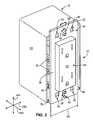
- FIG. 1is a perspective view of one embodiment of an electrical fixture having a wide safety strap in accordance with the present invention
- FIG. 2is a perspective view of the electrical fixture of FIG. 1 applied to a connection box in accordance with the present invention
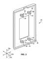
- FIG. 3is a perspective view of one embodiment of a face plate in accordance with the present invention for covering an electrical fixture such as that of FIG. 1 ;
- FIG. 4is a side, cross-sectional view of an engagement prong of a face plate approaching an engagement aperture formed in the flange of a safety strap in accordance with the present invention
- FIG. 5is a side, cross-sectional view of an engagement prong of a face plate deflecting inward to facilitate insertion thereof into an engagement aperture formed in the flange of a safety strap in accordance with the present invention
- FIG. 6is a side, cross-sectional view of an engagement prong of a face plate resiliently returned to its original shape once insertion is completed into an engagement aperture formed in the flange of a safety strap in accordance with the present invention
- FIG. 7is a partial, side, cross-sectional view of a face plate laminated with an aesthetic metal covering in accordance with the present invention.
- FIG. 8is a perspective, exploded view of one embodiment of a wide adapter in accordance with the present invention with a corresponding conventional electrical fixture to which the adapter may be retrofit;
- FIG. 9is a perspective view of the electrical fixture of FIG. 1 with a grounding clip applied thereto for grounding the metal portions of a face plate in accordance with the present invention
- FIG. 10is a perspective view of a face plate including an aesthetic metal covering and providing exposed portions on the back face of the metal covering to facilitate contact by a grounding clip in accordance with the present invention
- FIG. 11is a partial, end, cross-sectional view of grounding clip applied to an electrical fixture in accordance with the present invention.
- FIG. 12is a partial, end, cross-sectional view of the grounding clip and electrical fixture of FIG. 11 with the face plate of FIG. 10 applied thereto in accordance with the present invention
- FIG. 13is a perspective view of one embodiment of a grounding clip with barbs for resisting removal in accordance with the present invention.
- FIG. 14is a perspective view of one embodiment of a grounding clip with multiple extensions in accordance with the present invention.
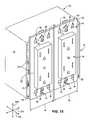
- FIG. 15is a perspective view of two electrical fixtures having a wide safety strap in accordance with the present invention positioned within a multi-gang connection box.
- an electrical fixture 10may secure to a connection box 12 in any suitable manner.
- one or more anchors 14 extending from an electrical fixture 10may engage one or more receivers formed in a corresponding connection box 12 .
- Such securementsare disclosed in U.S. Pat. No. 6,840,800, issued Jan. 11, 2005 and entitled DEFLECTING SECUREMENT ANCHOR FOR ELECTRICAL FIXTURES, which is incorporated herein by reference.
- electrical fixtures 10 in accordance with the present inventionmay include a main body 16 with a strap 18 or flange 18 extending away therefrom in longitudinal 20 a and lateral 20 b directions.
- the flange 18 of an electrical fixture 10may form a skirting 22 limiting access from the front 24 of the electrical fixture 10 to the terminals 26 located on the sides 28 or back 30 of the body 16 . Accordingly, when an electrical fixture 10 is secured to a connection box 12 , the skirting 22 may prevent inadvertent contact with the terminals 26 and, thereby, reduce the risk of electric shock.
- Skirting 22 in accordance with the present inventionmay be formed of any suitable materials. Suitable materials may include conductors as well as dielectrics.
- the skirting 22may be formed of a polymer exhibiting dielectric properties.
- the skirting 22may be monolithically formed (e.g., one piece) or even homogeneously formed (e.g., molded as a single material) with the face 32 of the body 16 .
- Skirting 22 in accordance with the present inventionmay have any suitable dimension.
- the skirting 22may have a width 34 in the lateral direction 20 b sufficient to cooperate with wall 35 of the connection box 12 in forming an enclosure that “passes code” without the addition of a face plate. That is, the skirting 22 may extend in the lateral direction 20 b an amount sufficient to stop objects of a codified size from being inserted within the connection box 12 (e.g., within the gap 36 between the skirting 22 and the open face of the connection box 12 ) to the point where they may contact a terminal 26 .
- the width 34 of the skirting 22may be selected to permit multiple electrical fixtures 10 to be installed laterally 20 b adjacent one another in a multi-gang connection box 12 .
- the skirting 22may extend in the longitudinal direction 20 a sufficient to hold the electrical fixture 10 flush with any wall paneling surrounding the connection box 12 .
- a flange 18may include one or more apertures 38 to accommodate the securement of an anchor 14 . Additional apertures 40 may provide locations for the engagement prongs of a face plate 20 to engage the flange 18 . Still other apertures 42 in the flange 18 may accommodate screws for securing traditional face plates.
- Face plates 44 in accordance with the present inventionmay have engagement prongs 46 .
- the prongs 46may be inserted through apertures 40 in a corresponding electrical fixture 10 to maintain the face plate 44 aligned securely thereagainst.
- an installermay first connect an electrical fixture 10 to the lines or wires housed in a connection box 12 .
- a face plate 44may be installed by simply pressing the engagement prongs 46 through the appropriate apertures 40 in the electrical fixture 10 .
- the electrical fixture 10may be secured to the connection box 12 by inserting one or more of the attached anchors 14 into corresponding receivers associated with the connection box 12 .
- the anchors 14may be inserted a selected distance into the receivers until the face plate 44 is properly positioned.
- Engagement prongs 46 in accordance with the present inventionmay be formed to have multiple extensions 48 .
- the extensions 48may be secured to the face plate 44 by flexible necks 50 .
- a flex clearance 52may be provided between the extensions 48 so that as the prong 46 is inserted 54 through an aperture 40 , the extensions 48 deflect inward 56 . Once the prong 46 has passed 58 through the aperture 40 , the extensions 48 may substantially resiliently return to their neutral position and engage the edges of the aperture 40 .
- the extensions 48may be shaped to release at a desired removal loading.
- the extensions 48may be provided with a taper 60 .
- the taper 60may allow each extension 48 to gradually flex and bend inward 56 into the flex clearance 52 as the face plate 44 is pulled away from the electrical fixture 10 .
- the taper 60may also tend to bias the engagement prongs 46 into complete engagement with the apertures 40 .
- Engagement prongs 46 in accordance with the present inventionmay have any suitable configuration.
- the number of prongs 46may range from one to several and be selected to provide a balanced securement between a face plate 44 and an electrical fixture 10 .
- an engagement prong 46is positioned within each of the four quadrants of the face plate 44 .
- each prong 46may also range from one to several (typically two to four), depending on a desired engagement strength, ease of manufacture, ease of installation, ease of removal, and the like. In one embodiment, each prong 46 includes two extensions 48 . Prongs 46 may grip inwardly (between) or outwardly against an aperture 40 .
- a screwless face plate 44 in accordance with the present inventionmay be formed of any suitable material. Characteristics considered when selecting a material may include, for example, cost, aesthetics, dielectric constant, thermal capacity, strength, toughness, flexibility, formability, and the like.
- a face plate 44 with corresponding engagement prongs 46may be monolithically formed of a polymer.
- the exterior face 62 of a face plate 44may have a coating 64 or laminant 64 applied thereto to provide a particular pattern, appearance, style, finish, or the like.
- a thin metal layer 64may be applied to the exterior face 62 of a face plate 44 .
- Such a thin metal layer 64may be formed of brass, brushed brass, nickel, brushed nickel, steel, stainless steel, oxidized iron, tin, aluminum, brushed aluminum, copper, oxidized copper, brushed copper, or the like.
- the coating 64may be applied in a lamination process using an adhesive. Other coating techniques are available.
- an adapter 66formed as a distinct and independent piece, may include the skirting 22 and apertures 38 , 40 , 42 necessary to interface between the face plate 44 and the conventional electrical fixture 10 .
- the fasteners used to secure a conventional electrical fixture 10 to a connection box 12may also secure the adapter 66 to the electrical fixture 10 .
- the fasteners used to secure anchors 14 to an electrical fixture 10may also secure the adapter 66 to the electrical fixture 10 .
- prongs 46extending through the apertures 40 of an adapter 66 , may interfere with the extensions 68 or “rabbit ears” sometimes found on the flanges 18 of conventional electrical fixtures 10 .
- the extensions 68typically already scored, may be broken off to provide proper clearance for the prongs 46 .
- An adapter 66 in accordance with the present inventionmay be formed of any suitable material. Suitable materials may include conductors as well as dielectrics.
- an adapter 66may be formed of a tough and hard polymer exhibiting certain dielectric properties and suitable for accepting pigmentation and molding in either a smooth satin or glossy finish.
- the skirting 22 of an adapter 66may have dimensions (e.g., width 34 ) as discussed hereinabove.
- a face plate 44may have a metal covering 64 . Accordingly, building regulations or codes may require that such a metal covering 64 be grounded. Alternatively, the entire face plate 44 may be formed of metal and require grounding.
- the one or more screws used to secure a face plate to the electrical fixtureprovided a grounding path. That is, metal screws typically formed an electrical connection between a metal face plate and the metal flange or interior of the electrical fixture. This metal flange or interior could then be grounded by a ground wire within the connection box 12 .
- an electrical fixture 10may include a grounding clip 70 .
- a grounding clip 70may be any device that creates a ground path between the metal portion or portions of a face plate 44 and a grounding wire within the connection box 12 .
- a grounding clip 70may engage the skirting 22 of an electrical fixture 10 and extend forward to contact the metal portion or portions of a face plate 44 .
- a clip 70may include a wire lead 72 extending backward toward the interior of the connection box 12 . Accordingly, the wire lead 72 may facilitate connection between the clip 70 and the grounding wire within the connection box 12 .
- the wire lead 72may extend a length sufficient to facilitate an engagement with the grounding wire within the connection box 12 using a twist-on wire connector.
- the wire lead 72may be omitted. In such embodiments, the grounding wire within the connection box 12 may extend to contact and engage the clip 70 directly.
- a clear pathmay be provided between the grounding clip 70 and the metal portion or portions (e.g., covering 64 ) of the face plate 44 .
- the back surface 74 of a metal covering 64may be exposed in the areas to be positioned transversely 20 c adjacent the portions of the skirting 22 extending in the lateral direction 20 b from the body 16 of the electrical fixture 10 .
- a grounding clip 70 positioned anywhere along the skirting 22 extending in the lateral direction 20 b from the body 16 of the electrical fixture 10may make grounding contact with the metal covering 64 .
- a grounding clip 70may include an engagement portion 76 and a contact portion 78 .
- the engagement portion 76may be primarily responsible for securing the clip 70 to the electrical fixture 10 (e.g., to the skirting 22 of the electrical fixture 10 ).
- the engagement portion 76may be configured as a spring loaded clamp formed of a conductive material (e.g., thin sheet metal). In such an arrangement, the engagement portion 76 may rely on the resiliency of the conductive material to provide the force necessary to squeeze or grip the skirting 22 therewithin.
- the wire lead 72may extend from one side of the engagement portion 76 while the contact portion 78 extends from the other.
- the contact portion 78 of a grounding clip 70may include an extension 80 or cantilever 80 extending to providing grounding contact with the metal portions of the face plate 44 .
- the resiliency of the conductive material forming the contact portion 78may provide the force necessary to bias the extension 80 or cantilever 80 against the metal covering 64 or other metal portions of the face plate 44 . Accordingly, the contact portion 78 may provided adequate grounding contact with face plates 44 of varying dimension or configuration.
- a grounding clip 70may be formed of a continuous section of thin sheet metal bent as necessary to form the engagement portion 76 and the contact portion 78 . If desired or necessary, in a neutral position, the mouth of the engagement portion 76 may have an opening height 82 less than the height 84 at the back of the engagement portion 78 . Once installed, this bias may improve the ability of the engagement portion 76 to squeeze or grip the electrical fixture 10 in the transverse direction 20 c.
- a lead wire 72may secure to a grounding clip 70 in any suitable manner.
- the engagement portion 76 of the grounding clip 70may include a lip 86 extending in substantially the transverse direction 20 c .
- the lip 86may facilitate application of the clip 70 to the electrical fixture 10 .
- the lip 86may provide a location for securing the wire lead 72 .
- the lip 86may provide a location to solder the wire lead 72 to the clip 70 .
- a lip 86may provide the material necessary for crimping the wire lead 72 to the clip 70 .
- the lip 86may provide a location for securing the grounding wire extending from within the connection box 12 . If desired or necessary, the lip 86 may be omitted.
- the wire lead 72 or grounding wire extending from within the connection box 12may connect to the grounding clip 70 at some other location.
- a grounding clip 70may be configured to resist removal after installation.
- the engagement portion 76 of a grounding clip 70may include one or more barbs 88 .
- Such barbs 88may permit the engagement portion 76 to be advanced unto the electrical fixture 10 , yet bite into the electrical fixture 10 to resist a removal force.
- the one or more barbs 88may be formed in a stamping process where an inwardly directed cantilever is cut from the base material of the engagement portion 76 .
- the contact portion 78 of a grounding clip 70may be formed to include more than one extension 80 or cantilever 80 extending to providing grounding contact with the metal portions of the face plate 44 .
- the different extensions 80may extend to contact different metal portions of the face plate 44 .
- the different extensionsmay increase the likelihood that at least one adequate grounding contact will be formed. That is, an obstacle or irregularity stopping one extension 80 from making proper contact should not stop the other extensions 80 from making contact. Accordingly, the grounding clip 70 may continue to perform its intended function.
- grounding clip 70may be applied to an electrical fixture 10 .
- a first grounding clip 70may ground a first metal portion of a face plate 44
- a second grounding clip 70may ground a second metal portion of the face plate 44 .
- the skirting 22may extend in the lateral direction 20 b an amount sufficient to stop objects of a codified size from being inserted within the connection box 12 (e.g., within the gap 36 between the skirting 22 and the open face of the connection box 12 ) to the point where they may contact a terminal 26 .
- the width 34 of the skirting 22may be selected to permit multiple electrical fixtures 10 to be installed laterally 20 b adjacent one another in a multi-gang connection box 12 .
- the skirting 22may extend in the longitudinal direction 20 a sufficiently to hold the electrical fixture 10 flush with any wall paneling surrounding the connection box 12 .
Landscapes
- Engineering & Computer Science (AREA)
- Architecture (AREA)
- Civil Engineering (AREA)
- Structural Engineering (AREA)
- Connector Housings Or Holding Contact Members (AREA)
- Clamps And Clips (AREA)
Abstract
Description
Claims (18)
Priority Applications (3)
| Application Number | Priority Date | Filing Date | Title |
|---|---|---|---|
| US11/605,721US7318732B2 (en) | 2005-01-11 | 2006-11-29 | Wide safety strap for electrical fixtures |
| US12/014,061US7611364B2 (en) | 2005-01-11 | 2008-01-14 | Wide safety strap for electrical fixtures |
| US12/610,971US8029301B2 (en) | 2005-01-11 | 2009-11-02 | Wide safety strap for electrical fixtures |
Applications Claiming Priority (5)
| Application Number | Priority Date | Filing Date | Title |
|---|---|---|---|
| US64301805P | 2005-01-11 | 2005-01-11 | |
| US67449905P | 2005-04-25 | 2005-04-25 | |
| US69791305P | 2005-07-07 | 2005-07-07 | |
| US11/328,650US7284996B2 (en) | 2005-01-11 | 2006-01-10 | Wide safety strap for electrical fixtures |
| US11/605,721US7318732B2 (en) | 2005-01-11 | 2006-11-29 | Wide safety strap for electrical fixtures |
Related Parent Applications (1)
| Application Number | Title | Priority Date | Filing Date |
|---|---|---|---|
| US11/328,650ContinuationUS7284996B2 (en) | 2005-01-11 | 2006-01-10 | Wide safety strap for electrical fixtures |
Related Child Applications (1)
| Application Number | Title | Priority Date | Filing Date |
|---|---|---|---|
| US12/014,061ContinuationUS7611364B2 (en) | 2005-01-11 | 2008-01-14 | Wide safety strap for electrical fixtures |
Publications (2)
| Publication Number | Publication Date |
|---|---|
| US20070082544A1 US20070082544A1 (en) | 2007-04-12 |
| US7318732B2true US7318732B2 (en) | 2008-01-15 |
Family
ID=36653847
Family Applications (4)
| Application Number | Title | Priority Date | Filing Date |
|---|---|---|---|
| US11/328,650Expired - Fee RelatedUS7284996B2 (en) | 2005-01-11 | 2006-01-10 | Wide safety strap for electrical fixtures |
| US11/605,721Expired - Fee RelatedUS7318732B2 (en) | 2005-01-11 | 2006-11-29 | Wide safety strap for electrical fixtures |
| US12/014,061Expired - Fee RelatedUS7611364B2 (en) | 2005-01-11 | 2008-01-14 | Wide safety strap for electrical fixtures |
| US12/610,971Expired - Fee RelatedUS8029301B2 (en) | 2005-01-11 | 2009-11-02 | Wide safety strap for electrical fixtures |
Family Applications Before (1)
| Application Number | Title | Priority Date | Filing Date |
|---|---|---|---|
| US11/328,650Expired - Fee RelatedUS7284996B2 (en) | 2005-01-11 | 2006-01-10 | Wide safety strap for electrical fixtures |
Family Applications After (2)
| Application Number | Title | Priority Date | Filing Date |
|---|---|---|---|
| US12/014,061Expired - Fee RelatedUS7611364B2 (en) | 2005-01-11 | 2008-01-14 | Wide safety strap for electrical fixtures |
| US12/610,971Expired - Fee RelatedUS8029301B2 (en) | 2005-01-11 | 2009-11-02 | Wide safety strap for electrical fixtures |
Country Status (3)
| Country | Link |
|---|---|
| US (4) | US7284996B2 (en) |
| CA (1) | CA2594622A1 (en) |
| WO (1) | WO2006091275A2 (en) |
Cited By (18)
| Publication number | Priority date | Publication date | Assignee | Title |
|---|---|---|---|---|
| US20060079125A1 (en)* | 2001-03-06 | 2006-04-13 | Kidman Brent L | Connection box assembly method |
| US20070272532A1 (en)* | 2006-05-24 | 2007-11-29 | Lutron Electronics Co., Inc. | Faceplate adapter for mounting a traditional-style load control device with a designer-style faceplate |
| USD573005S1 (en)* | 2006-09-01 | 2008-07-15 | Huadao Huang | Screwless wall plate |
| USD573006S1 (en)* | 2001-10-10 | 2008-07-15 | Cheetah Usa Corp. | Toggle-switch cover plate |
| USD576962S1 (en)* | 2001-10-10 | 2008-09-16 | Cheetah Usa Corp. | Wide-strap dimmer switch |
| USD576961S1 (en)* | 2001-10-10 | 2008-09-16 | Cheetah Usa Corp. | Wide-strap paddle switch |
| USD576866S1 (en)* | 2001-10-10 | 2008-09-16 | Cheetah Usa Corp. | Outlet fixture cover plate |
| USD577985S1 (en)* | 2001-10-10 | 2008-10-07 | Cheetah Usa Corp. | Switch cover plate |
| USD580740S1 (en)* | 2001-10-10 | 2008-11-18 | Cheetah Usa Corp. | Double-toggle cover plate |
| US20080293293A1 (en)* | 2007-05-22 | 2008-11-27 | Thomas & Betts International, Inc. | Electrical outlet box face plate with adapter plate |
| USD596925S1 (en)* | 2001-10-10 | 2009-07-28 | Cheetah Usa Corp. | Double switch cover plate |
| US20090211803A1 (en)* | 2005-05-17 | 2009-08-27 | Bticino S.P.A | Auxiliary support case for at least one piece of electrical equipment |
| US20100163267A1 (en)* | 2005-01-11 | 2010-07-01 | Kidman Brent L | Wide safety strap for electrical fixtures |
| US20110203828A1 (en)* | 2006-07-18 | 2011-08-25 | Leviton Manufacturing Co., Inc. | Wiring device and cover plate snap-on assembly |
| USRE43156E1 (en) | 2002-06-06 | 2012-02-07 | Leviton Manufacturing Co., Inc. | Receptacle with shaped surface |
| US20120287564A1 (en)* | 2011-05-11 | 2012-11-15 | Legrand Snc | Electrical equipotential mural apparatus |
| US9148005B2 (en) | 2013-03-14 | 2015-09-29 | Liberty Hardware Mfg. Corp. | Wall mounted electrical device cover plate assembly |
| US11101609B2 (en)* | 2017-07-24 | 2021-08-24 | Sapient Industries, Inc. | Custom power outlet socket that has integrated wireless functionality |
Families Citing this family (25)
| Publication number | Priority date | Publication date | Assignee | Title |
|---|---|---|---|---|
| US7419405B1 (en)* | 2007-09-12 | 2008-09-02 | Rock Landes | Dehumidifier safety cut-off system |
| USD661176S1 (en) | 2008-06-05 | 2012-06-05 | Schindler Stephen K | Receptacle cover |
| IT1392105B1 (en)* | 2008-11-28 | 2012-02-09 | Bticino Spa | COVER PLATE AND GROUP OF PARTS, INCLUDING SUCH PLATE, FOR WALL MOUNTING OF AN ELECTRIC APPLIANCE |
| IT1394201B1 (en)* | 2009-05-15 | 2012-06-01 | Mould Service Di Lucaboni Maurizio | SUPPORT STRUCTURE FOR ELECTRICAL OR ELECTRONIC DEVICES OF THE TYPE OF THOSE NORMALLY USED IN ELECTRICAL SYSTEMS. |
| US20110147037A1 (en)* | 2009-12-21 | 2011-06-23 | Leviton Manufacturing Co., Inc. | Interchangeable decorative bezel for wiring device |
| US9054449B2 (en) | 2012-01-27 | 2015-06-09 | Chatsworth Products, Inc. | Cable retention system for power distribution unit |
| US20130215581A1 (en) | 2012-01-27 | 2013-08-22 | Chatsworth Products, Inc. | Board-mounted circuit breakers for electronic equipment enclosures |
| WO2014179162A1 (en)* | 2013-05-02 | 2014-11-06 | Byrne Norman R | Interchangeable cover system |
| USD793343S1 (en)* | 2014-05-30 | 2017-08-01 | Norman R. Byrne | Receptacle for modular wiring systems |
| JP2017520887A (en) | 2014-06-05 | 2017-07-27 | チャッツワース プロダクツ、インク. | Electrical outlet with locking mechanism |
| USD788039S1 (en)* | 2014-07-23 | 2017-05-30 | Group Dekko, Inc. | Desktop receptacle faceplate |
| USD777685S1 (en) | 2015-04-01 | 2017-01-31 | Leviton Manufacturing Co., Inc. | Frameless wall switch |
| US9531177B1 (en)* | 2015-04-12 | 2016-12-27 | Arlington Industries, Inc. | TV bridge kit |
| USD853333S1 (en) | 2016-08-02 | 2019-07-09 | Eaton Intelligent Power Limited | USB type-C receptacle |
| BR102018000122A2 (en)* | 2017-01-04 | 2018-07-24 | R Byrne Norman | portable power towers |
| US10367317B1 (en)* | 2017-06-12 | 2019-07-30 | Premier Manufacturing Group, Inc. | Portable electric power hub with AC power receptacles and USB charging ports |
| GB2570148B (en)* | 2018-01-12 | 2022-09-14 | Focus Sb Ltd | An electrical fitting |
| US20190239368A1 (en)* | 2018-01-31 | 2019-08-01 | Zykronix, Inc. | Electrical box adapter plate |
| US10547145B2 (en)* | 2018-02-05 | 2020-01-28 | Chatworth Products, Inc. | Electric receptacle with locking feature |
| USD888001S1 (en) | 2018-03-27 | 2020-06-23 | Norman R. Byrne | Cargo net for a portable tower with electrical outlets |
| USD860950S1 (en)* | 2018-07-27 | 2019-09-24 | Schneider Electric (Australia) Pty Ltd | Multi-gang switch socket |
| US10390447B1 (en)* | 2018-12-05 | 2019-08-20 | Michael Dale McGee | Multi part plastic assembly that snaps into or is captured into existing plastic or metal junction boxes, switch boxes and receptacle boxes to simplify connection wiring to individual switches, receptacles, USB ports, GFCIS |
| USD962171S1 (en) | 2019-08-30 | 2022-08-30 | Schneider Electric (Australia) Pty Ltd | Socket |
| US11005247B1 (en) | 2020-11-11 | 2021-05-11 | JPoint Innovation LLC | Junction box interface chassis and pluggable modular devices |
| US12308557B2 (en)* | 2022-12-11 | 2025-05-20 | Jasco Products Company, LLC | Slide on off receptacle panel device |
Citations (23)
| Publication number | Priority date | Publication date | Assignee | Title |
|---|---|---|---|---|
| US1726429A (en)* | 1928-10-06 | 1929-08-27 | Reynolds Spring Co | Duplex receptacle |
| US1785463A (en)* | 1925-10-19 | 1930-12-16 | Herman L Strongson | Duplex receptacle |
| US2740873A (en) | 1952-07-17 | 1956-04-03 | Touch Plate Mfg Corp | Household switch mechanism |
| US2860317A (en)* | 1957-02-19 | 1958-11-11 | Allard R Johnson | Electrical outlet with detachable face plate |
| US2920303A (en)* | 1958-03-05 | 1960-01-05 | Allard R Johnson | Electrical terminal box construction with detachable face plate and wire tapping means therefor |
| US3437737A (en)* | 1965-10-11 | 1969-04-08 | Milan Francis Wagner | Modular unit outlet |
| US4500746A (en) | 1980-03-14 | 1985-02-19 | Slater Electric Inc. | Self-contained electrical wiring device |
| US5073681A (en) | 1990-08-16 | 1991-12-17 | Pass & Seymour, Inc. | Two-piece wall plate for electrical device |
| US5153816A (en) | 1991-04-25 | 1992-10-06 | Lightolier Incorporated | Face plate with decorator insert |
| US5180886A (en)* | 1989-08-09 | 1993-01-19 | Lutron Electronics Co., Inc. | Wallbox electric device assembly |
| US5189259A (en)* | 1990-05-17 | 1993-02-23 | Lightolier, Inc. | Face plate having press-fit attachment to electrical switches, outlets and the like |
| US5223673A (en) | 1990-12-10 | 1993-06-29 | Mason Gay L | Modular electrical outlet assembly |
| US5477010A (en)* | 1993-09-17 | 1995-12-19 | Buckshaw; Dennis J. | Safety plate assembly |
| US5623124A (en)* | 1995-03-27 | 1997-04-22 | Chien; Chi-Hua | Wall switch housing |
| US5723817A (en)* | 1994-01-14 | 1998-03-03 | Leviton Manufacturing Co., Inc. | Snap-on wallplate system |
| US6005308A (en) | 1993-03-31 | 1999-12-21 | Lutron Electronics Co., Inc. | Electrical switch and dimmer control device |
| US6109937A (en) | 1999-02-19 | 2000-08-29 | Hubbell Incorporated | Four-sided ground contact assembly |
| US6147304A (en) | 1999-03-05 | 2000-11-14 | Doherty; James W. | Electrical outlet box |
| US6376770B1 (en) | 2000-02-28 | 2002-04-23 | Douglas Hyde | Quick connecting universal electrical box and wiring system |
| US6410850B1 (en) | 2000-02-08 | 2002-06-25 | Avaya Technology Corp. | Cable enclosure assembly |
| US6609927B2 (en) | 2001-03-06 | 2003-08-26 | Quixemble Inc. | Quick assembling electrical connection box apparatus and method |
| US6974910B2 (en) | 2003-11-26 | 2005-12-13 | Pass & Seymour, Inc. | Screwless faceplate components and assembly |
| US7071414B2 (en)* | 2004-01-16 | 2006-07-04 | Kim Kyung T | Cover plate for electrical outlets and switches |
Family Cites Families (210)
| Publication number | Priority date | Publication date | Assignee | Title |
|---|---|---|---|---|
| US867624A (en) | 1906-07-28 | 1907-10-08 | Harry J Warthen | Switch-box. |
| US1113762A (en) | 1914-01-30 | 1914-10-13 | Gustavus A Eckman | Mount for electric fittings. |
| US1840582A (en)* | 1926-04-05 | 1932-01-12 | Louie E Hubbell | Mounting for cover plates for switches and receptacles |
| US1933358A (en) | 1929-04-15 | 1933-10-31 | Edward L Kappelman | Outlet box |
| US1964535A (en) | 1929-09-02 | 1934-06-26 | Gen Electric | Means for securing electrical devices in outlet boxes |
| US2043865A (en) | 1931-01-09 | 1936-06-09 | George E Gagnier | Securing electrical cover or escutcheon plate |
| US2149719A (en)* | 1937-04-13 | 1939-03-07 | Harry L Arnest | Electric outlet box |
| US2297862A (en) | 1939-08-30 | 1942-10-06 | Walter H Bachmann | Switch box |
| US2515820A (en) | 1945-10-15 | 1950-07-18 | George P R Clark | Luminous display unit |
| US2512188A (en) | 1947-04-01 | 1950-06-20 | William H Wait | Outlet box support |
| US2794890A (en) | 1953-11-13 | 1957-06-04 | Lloyd E Taylor | Push plate operated switch |
| US2828394A (en)* | 1956-08-24 | 1958-03-25 | Peter P Mayzik | Adaptor unit |
| US2934590A (en)* | 1958-08-29 | 1960-04-26 | Harry B Thompson | Electric outlet receptacle |
| US2980756A (en)* | 1958-09-29 | 1961-04-18 | John E Kelleher | Electrical outlet leveler |
| US3155808A (en) | 1961-04-18 | 1964-11-03 | Westinghouse Electric Corp | Nonlatching resilient fastening arrangement |
| US3168612A (en)* | 1962-10-10 | 1965-02-02 | Carling Electric Inc | Mounting adapters for switch cases |
| US3488428A (en)* | 1967-07-17 | 1970-01-06 | Charles E Smith | Electrical receptacle |
| US3609213A (en) | 1970-11-02 | 1971-09-28 | Paul H Winter | Automatic grounding for receptacle |
| US3689868A (en) | 1970-11-20 | 1972-09-05 | Dtm Products Inc | Cord storing face plate |
| US3662085A (en)* | 1971-03-12 | 1972-05-09 | Gen Cable Corp | Mounting bracket for switch or receptacle |
| US3955463A (en)* | 1971-08-09 | 1976-05-11 | Slater Electric Inc. | Screw mounting means |
| US3735020A (en)* | 1971-09-29 | 1973-05-22 | Lutron Electronics Co | Heat sink wall plate with off-center mounting openings |
| US3767151A (en) | 1971-11-12 | 1973-10-23 | G Seal | Electric wiring box positioner |
| US3770872A (en) | 1971-11-17 | 1973-11-06 | Electrical Fittings Corp | Electrical outlet box construction |
| US3770920A (en) | 1972-02-09 | 1973-11-06 | Leviton Manufacturing Co | Rocker-type electrical switch |
| US3810069A (en) | 1972-08-08 | 1974-05-07 | Hubbell Inc Harvey | Grounding clip for electrical fixtures |
| US3848764A (en) | 1972-08-25 | 1974-11-19 | Reflect O Lite Mfg Co | Electrical box structure for securement to wall paneling without separate fasteners |
| US3814834A (en) | 1972-11-13 | 1974-06-04 | J Glader | Electrical outlet box |
| US3905570A (en) | 1972-11-27 | 1975-09-16 | Aril J Nieuwveld | Resilient fastening devices |
| US4105862A (en) | 1973-07-30 | 1978-08-08 | Slater Electric Inc. | Outlet box having screw mounting means |
| US3859454A (en)* | 1973-09-13 | 1975-01-07 | Production Products Inc | Cover plate |
| US3928716A (en) | 1973-12-13 | 1975-12-23 | Louis Marrero | Electrical outlet box assembly |
| US3953933A (en)* | 1974-01-09 | 1976-05-04 | Dilly Mfg. Co., Inc. | Cover plate assembly |
| US3926330A (en) | 1974-03-13 | 1975-12-16 | All Steel Inc | Knockout arrangement for molded plastic electrical boxes |
| US3908235A (en)* | 1974-12-02 | 1975-09-30 | Gregory Alan Telliard | Removable snap fastener |
| US4165443A (en) | 1975-07-24 | 1979-08-21 | Figart Earl C | Power distribution system |
| US4007852A (en)* | 1975-10-20 | 1977-02-15 | Slater Electric Inc. | Knockout window means |
| US3982084A (en) | 1975-10-23 | 1976-09-21 | The Raymond Lee Organization, Inc. | Shockproof electrical wall receptacle |
| US4057164A (en) | 1976-02-20 | 1977-11-08 | William Maier | Electrical outlet box mounting |
| US4062470A (en) | 1976-08-04 | 1977-12-13 | Slater Electric Inc. | Electrical outlet box mounting assembly |
| US4098423A (en) | 1977-03-10 | 1978-07-04 | Louis Marrero | Self-aligning outlet box assembly |
| US4281773A (en) | 1977-07-25 | 1981-08-04 | Gte Products Corporation | Electrical wiring box |
| US4389535A (en) | 1978-02-21 | 1983-06-21 | Slater Electric Inc. | Cable entry port means for electrical outlet box |
| CA1137608A (en)* | 1979-05-23 | 1982-12-14 | Joseph S. Maheu | Electrical box |
| US4273957A (en) | 1979-06-06 | 1981-06-16 | Kolling Jr William J | Telecommunications access apparatus |
| US4315100A (en)* | 1979-12-06 | 1982-02-09 | Highland Manufacturing Company, Ltd. | Electrical box |
| US4295003A (en) | 1980-01-07 | 1981-10-13 | Illinois Tool Works Inc. | Threaded screw mounting means |
| US4304958A (en) | 1980-03-03 | 1981-12-08 | Neff Steve W | Electrical outlet box |
| US4311422A (en)* | 1980-05-19 | 1982-01-19 | Midland-Ross Corporation | Screw retainer |
| US4316999A (en)* | 1980-07-23 | 1982-02-23 | Gte Sylvania Canada Limited | Electrical wiring box and cable clamp |
| US4340795A (en) | 1980-07-29 | 1982-07-20 | Amf Incorporated | Panel mount adapter for switches |
| US4348547A (en) | 1980-10-24 | 1982-09-07 | Slater Electric Inc. | Electrical outlet box with recessed ports |
| US4306109A (en) | 1980-11-17 | 1981-12-15 | Gte Sylvania Canada Limited | Electrical wiring box arrangements |
| US4355198A (en) | 1981-01-19 | 1982-10-19 | Harvey Hubbell Incorporated | Screw retaining and aligning cover plate |
| US4408696A (en) | 1981-05-07 | 1983-10-11 | Westmoreland Plastics Company | Removable electrical receptacle |
| US4399922A (en)* | 1981-09-14 | 1983-08-23 | Larry Horsley | Outlet box mounting |
| USD269510S (en) | 1981-10-07 | 1983-06-28 | Leviton Manufacturing Co., Inc. | Electronic receptacle |
| US4436952A (en)* | 1981-12-28 | 1984-03-13 | Lockwood Alan C | Cable clamping device integrally formed with plastic molded electrical box |
| US4489297A (en) | 1982-03-15 | 1984-12-18 | Haydon Arthur W | Magnetic switch |
| US4833277A (en)* | 1982-10-04 | 1989-05-23 | Lutron Electronics Co., Inc. | Wall plate insert |
| US4534486A (en) | 1984-03-29 | 1985-08-13 | Eidson Lawrence E | Cover plate fastening device |
| US4580689A (en)* | 1984-06-01 | 1986-04-08 | Harvey Hubbell Incorporated | Electrical outlet box with integral screw aligning, engaging and retaining boss |
| US4605816A (en) | 1985-02-19 | 1986-08-12 | Harvey Hubbell Incorporated | Molded outlet box with integral cable clamp |
| US4631354A (en)* | 1985-05-13 | 1986-12-23 | Harvey Hubbell Incorporated | Cover assembly for electrical outlet box |
| US4724282A (en)* | 1985-06-10 | 1988-02-09 | Allied Moulded Products, Inc. | Electrical box |
| US4669804A (en) | 1985-06-14 | 1987-06-02 | Eagle Electric Mfg. Co., Inc. | Wall-mountable wiring installation |
| CA1277409C (en) | 1986-02-20 | 1990-12-04 | Robert W. Jorgensen | Screw attachment for electrical box |
| CA1271832A (en)* | 1986-03-19 | 1990-07-17 | Sadamasa Tanaka | Wiring-device mounting structure |
| US4669797A (en) | 1986-04-06 | 1987-06-02 | Allied Corporation | Electrical connector assembly having a locking arrangement |
| US4688693A (en) | 1986-08-04 | 1987-08-25 | Medlin Jr Lewis B | Outlet box bracket with stabilizer |
| US4732356A (en)* | 1986-10-23 | 1988-03-22 | Medlin Sr Lewis B | Outlet box bracket with adjustable stabilizer |
| US4793059A (en) | 1987-02-24 | 1988-12-27 | Pass & Seymour, Inc. | Automatic grounding clip |
| US4835343A (en)* | 1987-03-30 | 1989-05-30 | Lutron Electronics Co., Inc. | Two piece face plate for wall box mounted device |
| US4837406A (en) | 1987-05-29 | 1989-06-06 | Emmons David J | Face plate and electrical component assembly |
| US4832297A (en)* | 1987-09-29 | 1989-05-23 | Sasco Energy | Device for installing an electrical outlet box |
| US5224673A (en) | 1987-11-09 | 1993-07-06 | Webb Ronald D | Electrical junction box mounting bracket device and method |
| US4810199A (en)* | 1987-11-25 | 1989-03-07 | Kar Kishore K | Safety electrical plug |
| US4844275A (en) | 1988-07-01 | 1989-07-04 | Hubbell Incorporated | Non-metallic electrical connection housing |
| US4903851A (en) | 1988-07-07 | 1990-02-27 | Slough Donovan L | Molded plastic stud box support and box |
| US4974888A (en) | 1988-07-25 | 1990-12-04 | The Vendo Company | Fastening apparatus |
| JP2581776B2 (en) | 1988-09-08 | 1997-02-12 | 松下電工株式会社 | Makeup structure of wiring equipment |
| US4843189A (en) | 1988-09-20 | 1989-06-27 | Hubbell Incorporated | Screw attachment pocket with guide tab |
| US4939383A (en) | 1988-10-14 | 1990-07-03 | Lutron Electronics Co., Inc. | Wallbox-mountable dimmer and switch |
| US4909692A (en)* | 1988-12-12 | 1990-03-20 | Hendren Stephen R | Electrical receptacle mounting spacers |
| US4898357A (en)* | 1988-12-15 | 1990-02-06 | Hubbell Incorporated | Electrical box support |
| US5117122A (en)* | 1989-01-19 | 1992-05-26 | Hogarth Peter T | Integrated outlet for communication and electrical power transmissions with noise reducing characteristics |
| US4936396A (en) | 1989-02-08 | 1990-06-26 | Masco Building Products Corp. | Fastener arrangement for electrical junction box or the like |
| US4960964A (en) | 1989-02-15 | 1990-10-02 | Hubbell Incorporated | Quick set grounding assembly |
| US4954667A (en) | 1989-02-15 | 1990-09-04 | Hubbell Incorporated | Electrical box with coupling members |
| US5170014A (en) | 1989-03-21 | 1992-12-08 | The Lamson & Sessions Co. | Mounting fastener for electrical wiring boxes |
| US5135411A (en)* | 1989-04-19 | 1992-08-04 | Hubbell Incorporated | Multiple outlet receptacle and mountings therefor |
| US4948317A (en) | 1989-05-01 | 1990-08-14 | Carl Marinaro | Method and device for electrical fitting stabilization |
| CA1317366C (en) | 1989-06-22 | 1993-05-04 | William Nattel | Universal support bracket for attachment to the back of an electrical box |
| USD336744S (en) | 1989-08-10 | 1993-06-22 | Lutron Electronics Co., Inc. | Wall-mounted lighting control |
| US4964525A (en) | 1989-09-21 | 1990-10-23 | G.B. Electrical Inc. | Electrical box mounting bracket |
| US4927373A (en)* | 1989-10-26 | 1990-05-22 | Paige Manufacturing Company, Inc. | Electrical safety receptacle assembly |
| US5031785A (en) | 1990-02-14 | 1991-07-16 | Epicurean International Corp. | Combination vacuum/pressure pump and valve stopper for food or drink containers |
| US5031789A (en) | 1990-04-13 | 1991-07-16 | Fl Industries, Inc. | Standoff for outlet boxes |
| US5084596A (en)* | 1990-06-04 | 1992-01-28 | The Lamson & Sessions Co. | Electrical box |
| USD327212S (en) | 1990-06-04 | 1992-06-23 | Pass & Seymour, Inc. | Wall plate for electrical wiring device |
| US5407088A (en)* | 1990-06-29 | 1995-04-18 | Incorporated Hubbell | Plastic box assembly for ceiling fixture support |
| US5064386A (en) | 1990-11-27 | 1991-11-12 | Amp Incorporated | Convenience electrical outlet assembly |
| US5176345A (en)* | 1991-01-10 | 1993-01-05 | Medlin Pauline B | Extension plate for outlet box bracket |
| USD364141S (en) | 1992-03-31 | 1995-11-14 | Lutron Electronics Co., Inc. | Combined bezel and actuator for dimmer switch |
| US5207317A (en)* | 1992-03-31 | 1993-05-04 | Lutron Electronics Co., Inc. | Snap-action switch actuator |
| US5415564A (en)* | 1992-09-14 | 1995-05-16 | Winter; Craig | Junction box for quick release mounting of electrical circuit components |
| USD346949S (en)* | 1992-11-04 | 1994-05-17 | Molex Incorporated | Receptacle cover plate |
| US5277602A (en)* | 1992-11-25 | 1994-01-11 | Yi Lee M | Electrical plug and receptacle assembly |
| US5595362A (en)* | 1992-12-17 | 1997-01-21 | B-Line Systems, Inc. | Electrical box mounting bracket |
| US5375728A (en) | 1993-06-21 | 1994-12-27 | West; Frank L. | Assembly for covering a wall-mounted electrical outlet |
| US5306178A (en)* | 1993-07-23 | 1994-04-26 | Min Huang | Phone jack box |
| US5456373A (en)* | 1993-08-23 | 1995-10-10 | Ds Inc. | Cover plate assembly |
| US5289934A (en)* | 1993-09-02 | 1994-03-01 | Smith Benjamin H | Adjustable mounting assembly for electrical outlet box |
| USD354943S (en)* | 1993-11-04 | 1995-01-31 | Williams Jesse D | 110/220 volt receptacle |
| USD360876S (en) | 1994-01-19 | 1995-08-01 | Hughes Richard R | Switch plate cover |
| US5965846A (en)* | 1994-09-21 | 1999-10-12 | Taymac Corporation | Receptacle-mounted cover plate to hide electrical socket face |
| US6160219A (en) | 1994-09-21 | 2000-12-12 | Maltby; Edgar W. | Receptacle-mounted cover plate |
| US5596174A (en)* | 1994-10-04 | 1997-01-21 | Sapienza; Joseph | Expandable electrical outlet box |
| CA2137011C (en)* | 1994-11-30 | 2001-10-23 | Gordon S. Almond | Modular electrical connector box |
| US6207898B1 (en)* | 1995-01-12 | 2001-03-27 | Reiker Enterprises Of Northwest Florida, Inc. | Electrical box with fixture support |
| US5965845A (en) | 1995-01-12 | 1999-10-12 | Reiker; Kenneth H. | Electrical box with cutout and support for carrying fixtures |
| US5696350A (en) | 1995-01-18 | 1997-12-09 | Leviton Manufacturing Co., Inc. | Interchangeable sectional wallplates |
| US5594208A (en)* | 1995-02-02 | 1997-01-14 | The Wiremold Company | Molded plastic electric outlet box with snap-on base and snap-on face plate |
| US5538437A (en) | 1995-03-03 | 1996-07-23 | Itt Industries, Inc. | Connector assembly for IC card |
| US5599512A (en)* | 1995-05-10 | 1997-02-04 | Poly Vac, Incorporated | Sterilization support and storage container system |
| US6066805A (en)* | 1995-05-30 | 2000-05-23 | Thomas & Betts Corporation | Electrical receptacle cover having an integrally formed detachable fastening nut |
| CA2153298C (en)* | 1995-07-05 | 2002-05-14 | Alain Bourassa | Device box support |
| US5675125A (en)* | 1996-02-12 | 1997-10-07 | American Tack & Hardware Co., Inc. | Screwless outlet box covering |
| US6355885B1 (en)* | 1996-05-02 | 2002-03-12 | William J. Rintz | Sub frame assembly for light switch assembly |
| US6051787A (en)* | 1996-05-02 | 2000-04-18 | Rintz; William J. | Light switch cover |
| USD401566S (en) | 1996-05-23 | 1998-11-24 | The Siemon Company | Cable management enclosure |
| US5842822A (en) | 1996-07-19 | 1998-12-01 | Everett Industries Inc | Removable quasi-ratchet fastener |
| US5833110A (en) | 1996-08-23 | 1998-11-10 | Thomas & Betts Corporation | Electrical outlet box with integral support leg |
| US5706559A (en)* | 1996-10-18 | 1998-01-13 | Eaton Corporation | Leaf spring tip insert |
| US5863016A (en)* | 1997-02-28 | 1999-01-26 | The Wiremold Company | Modular faceplate assembly having concealed latching means |
| US6191361B1 (en)* | 1997-04-07 | 2001-02-20 | George T. Matty | Terminal electrical receptacle outlet box |
| US5900584A (en)* | 1997-05-06 | 1999-05-04 | Cady; James L. | Enlarged wall switch plate |
| US5954643A (en)* | 1997-06-09 | 1999-09-21 | Minimid Inc. | Insertion set for a transcutaneous sensor |
| US5835980A (en) | 1997-08-06 | 1998-11-10 | American Tack & Hardware Co, Inc. | Receptacle plate |
| USD405760S (en)* | 1997-09-08 | 1999-02-16 | Jeff Yu | Receptacle having a safety cover |
| USD405761S (en)* | 1997-09-08 | 1999-02-16 | Jeff Yu | Receptacle having a safety cover |
| US6093890A (en) | 1997-09-22 | 2000-07-25 | Arlington Industries, Inc. | Mounting device |
| US6107568A (en) | 1998-03-19 | 2000-08-22 | Hubbell Incorporated | Electrical box and holding device for use therewith |
| US6040967A (en)* | 1998-08-24 | 2000-03-21 | Leviton Manufacturing Co., Inc. | Reset lockout for circuit interrupting device |
| US7463124B2 (en) | 1998-08-24 | 2008-12-09 | Leviton Manufacturing Co., Inc. | Circuit interrupting device with reverse wiring protection |
| USD419531S (en)* | 1998-10-26 | 2000-01-25 | Rototech Electrical Components | Ground fault circuit interrupter |
| US6036536A (en)* | 1998-12-31 | 2000-03-14 | Chiu; Jin-Hsien | Different features in the structure of an electrical outlet |
| US6023021A (en)* | 1999-01-15 | 2000-02-08 | Pass & Seymour, Inc. | Reinforced thermoplastic elastomer wall plate with captive screw |
| USD430539S (en) | 1999-02-17 | 2000-09-05 | Eagle Electric Manufacturing Co., Inc. | Protective electrical receptacle |
| US5950812A (en) | 1999-03-26 | 1999-09-14 | Leviton Manufacturing Co., Inc. | Rocker switch using a star spring |
| US6166329A (en) | 1999-06-10 | 2000-12-26 | America Cable Systems | Protecting electrical device assemblies during installation |
| WO2001001525A1 (en)* | 1999-06-28 | 2001-01-04 | Reiker Electric Llc | Electrical outlet box |
| US6423897B1 (en) | 1999-08-09 | 2002-07-23 | The Lamson & Sessions Co. | Electrical utility box |
| US6229087B1 (en)* | 1999-08-17 | 2001-05-08 | Thomas & Betts International, Inc. | Gangable electrical box |
| US6184466B1 (en)* | 1999-09-02 | 2001-02-06 | Leviton Manufacturing Co., Inc. | Wallplate retention device |
| US6218617B1 (en)* | 1999-10-15 | 2001-04-17 | Leviton Manufacturing Co., Inc. | Snap-on wallplate and heat sink assembly |
| US6341981B1 (en)* | 2000-01-05 | 2002-01-29 | Michael P. Gorman | Safety electrical outlet and switch system |
| US6365831B1 (en)* | 2000-01-11 | 2002-04-02 | Allied Moulded Products, Inc. | Electrical box |
| JP3679306B2 (en)* | 2000-04-10 | 2005-08-03 | 矢崎総業株式会社 | Indoor equipment mounting bracket |
| US6441304B1 (en) | 2000-05-05 | 2002-08-27 | The Wiremold Company | Electrical outlet assembly |
| US6552269B1 (en)* | 2000-06-16 | 2003-04-22 | Patricia Conner | Electrical outlet cover |
| US6257925B1 (en) | 2000-07-05 | 2001-07-10 | Hon Hai Precision Ind. Co., Ltd. | Pair of connectors clamping a printed circuit board |
| US6616005B1 (en) | 2000-08-28 | 2003-09-09 | Hubbell Incorporated | Modular faceplate assembly for an electrical box |
| US6384334B1 (en)* | 2000-09-11 | 2002-05-07 | Ronald D. Webb | Electrical junction box and support bracket having sliding attachment |
| US6679725B2 (en)* | 2001-10-10 | 2004-01-20 | Quixemble, Inc. | Clip-on cover plate for electrical fixtures |
| US7306482B1 (en) | 2001-03-06 | 2007-12-11 | Cheetah Usa Corp. | Electrical connection box |
| US7083467B2 (en) | 2001-03-06 | 2006-08-01 | Quixemble, Inc. | Connection box stabilizer |
| US6840800B2 (en)* | 2001-10-10 | 2005-01-11 | Quixemble, Inc. | Deflecting securement anchor for electrical fixtures |
| US7049511B2 (en) | 2003-01-15 | 2006-05-23 | Quixemble, Inc. | Connection box stabilizer |
| US7118413B2 (en)* | 2001-10-10 | 2006-10-10 | Quixemble, Inc. | Quick assembling electrical connection box apparatus and method |
| USD480832S1 (en)* | 2001-04-03 | 2003-10-14 | Joseph G. Angeletta | Combined palm-held liquid and lotion applicator and cover |
| US6452813B1 (en) | 2001-05-10 | 2002-09-17 | Arlington Industries, Inc. | One-piece terminal device for low-voltage cable system |
| US20030014939A1 (en)* | 2001-07-20 | 2003-01-23 | Dewall Harold O. | Junction box and fixture installation method |
| USD576961S1 (en) | 2001-10-10 | 2008-09-16 | Cheetah Usa Corp. | Wide-strap paddle switch |
| USD576962S1 (en) | 2001-10-10 | 2008-09-16 | Cheetah Usa Corp. | Wide-strap dimmer switch |
| USD577985S1 (en) | 2001-10-10 | 2008-10-07 | Cheetah Usa Corp. | Switch cover plate |
| USD580740S1 (en) | 2001-10-10 | 2008-11-18 | Cheetah Usa Corp. | Double-toggle cover plate |
| USD573006S1 (en) | 2001-10-10 | 2008-07-15 | Cheetah Usa Corp. | Toggle-switch cover plate |
| USD576866S1 (en) | 2001-10-10 | 2008-09-16 | Cheetah Usa Corp. | Outlet fixture cover plate |
| USD596925S1 (en) | 2001-10-10 | 2009-07-28 | Cheetah Usa Corp. | Double switch cover plate |
| US7077695B2 (en) | 2001-10-10 | 2006-07-18 | Quixemble, Inc. | Clip-on face plate for electrical fixtures |
| USD484392S1 (en) | 2001-11-13 | 2003-12-30 | Lutron Electronics Co., Inc. | Screwless faceplate |
| US6533225B1 (en)* | 2001-12-03 | 2003-03-18 | Dana Innovations | Wall-mounted audio control housing and receptacle therefor |
| AU2003248564A1 (en)* | 2002-05-23 | 2003-12-12 | Protectconnect, Inc. | Safety module electrical distribution system |
| US20030226683A1 (en) | 2002-06-06 | 2003-12-11 | Anthony Tufano | Robust wiring device cover plate |
| US7279636B2 (en) | 2002-06-06 | 2007-10-09 | Leviton Manufacturing Co., Inc. | Multifunction clips and ground/mounting strap for wiring device |
| US20030226682A1 (en) | 2002-06-06 | 2003-12-11 | Anthony Tufano | Alignment plate for wiring devices |
| US20030226681A1 (en) | 2002-06-06 | 2003-12-11 | Leslie Lindenstraus | Robust receptacle system |
| US7052314B1 (en) | 2002-11-04 | 2006-05-30 | Intumescent Technologies, Llc | Electrical device with mounting system |
| US6624355B1 (en) | 2002-11-07 | 2003-09-23 | Arlington Industries, Inc. | Low-voltage mounting bracket |
| US6814611B1 (en) | 2003-04-14 | 2004-11-09 | Henoc T. Torres | Power surge protectorant electrical outlet assembly |
| US7048575B2 (en) | 2003-05-12 | 2006-05-23 | Quixemble, Inc. | Panel-mounted, low voltage terminal |
| ES2253031B1 (en) | 2003-06-17 | 2006-12-01 | Simon, S.A. | IMPROVEMENTS INTRODUCED IN THE LOW VOLTAGE ELECTRICAL DEVICES DESIGNED ON A PLUG BASE. |
| US6875940B2 (en)* | 2003-07-25 | 2005-04-05 | Leviton Manufacturing Co., Inc. | Robust rocker switch mechanism |
| CA2533655A1 (en) | 2003-07-25 | 2005-02-10 | Leviton Manufacturing Co., Inc. | Rocker paddle switch with flexible cam driver |
| BRPI0412930A (en) | 2003-07-25 | 2006-09-26 | Leviton Manufacturing Co | switch |
| US6765149B1 (en)* | 2003-09-26 | 2004-07-20 | Fa Chai Ku | Wall box having light device |
| US6891117B1 (en) | 2003-11-07 | 2005-05-10 | Cooper Wiring Devices, Inc. | Modular block switch assembly |
| USD512377S1 (en) | 2003-11-10 | 2005-12-06 | Cooper Wiring Devices, Inc. | Decorator receptacles |
| USD558676S1 (en)* | 2003-11-10 | 2008-01-01 | Cooper Wiring Devices, Inc. | Portion of a decorator receptacle |
| US7030319B2 (en)* | 2004-02-25 | 2006-04-18 | Control4 Corporation | Faceplate attachment system |
| CN2699455Y (en) | 2004-05-20 | 2005-05-11 | 徐少杰 | Switch panel |
| US6949708B1 (en)* | 2004-08-06 | 2005-09-27 | Hausen Daniel M | Frictionally mounted utility switch box masking cover |
| US20060048964A1 (en)* | 2004-09-08 | 2006-03-09 | Rick Electrical Contractors, Inc. | Electrical connection system |
| US7102081B2 (en)* | 2004-10-27 | 2006-09-05 | Shaojie Xu | Decorative cover plate assembly |
| US7342173B1 (en)* | 2005-01-11 | 2008-03-11 | Cheetah Usa Corp. | Multi-directional-port junction box |
| US7284996B2 (en)* | 2005-01-11 | 2007-10-23 | Cheetah Usa Corp. | Wide safety strap for electrical fixtures |
| US7122753B1 (en) | 2005-03-28 | 2006-10-17 | Ralph Kenneth Davis | Cover plate with flush slide actuator for electrical devices |
| US7077706B1 (en) | 2005-08-22 | 2006-07-18 | Sun-Lite Sockets Industry Inc. | Cover for terminal screws of a receptacle |
| USD534875S1 (en)* | 2005-12-12 | 2007-01-09 | Leviton Manufacturing Co., Inc. | Box mounted dimmer |
- 2006
- 2006-01-10USUS11/328,650patent/US7284996B2/ennot_activeExpired - Fee Related
- 2006-01-11CACA002594622Apatent/CA2594622A1/ennot_activeAbandoned
- 2006-01-11WOPCT/US2006/000879patent/WO2006091275A2/enactiveApplication Filing
- 2006-11-29USUS11/605,721patent/US7318732B2/ennot_activeExpired - Fee Related
- 2008
- 2008-01-14USUS12/014,061patent/US7611364B2/ennot_activeExpired - Fee Related
- 2009
- 2009-11-02USUS12/610,971patent/US8029301B2/ennot_activeExpired - Fee Related
Patent Citations (23)
| Publication number | Priority date | Publication date | Assignee | Title |
|---|---|---|---|---|
| US1785463A (en)* | 1925-10-19 | 1930-12-16 | Herman L Strongson | Duplex receptacle |
| US1726429A (en)* | 1928-10-06 | 1929-08-27 | Reynolds Spring Co | Duplex receptacle |
| US2740873A (en) | 1952-07-17 | 1956-04-03 | Touch Plate Mfg Corp | Household switch mechanism |
| US2860317A (en)* | 1957-02-19 | 1958-11-11 | Allard R Johnson | Electrical outlet with detachable face plate |
| US2920303A (en)* | 1958-03-05 | 1960-01-05 | Allard R Johnson | Electrical terminal box construction with detachable face plate and wire tapping means therefor |
| US3437737A (en)* | 1965-10-11 | 1969-04-08 | Milan Francis Wagner | Modular unit outlet |
| US4500746A (en) | 1980-03-14 | 1985-02-19 | Slater Electric Inc. | Self-contained electrical wiring device |
| US5180886A (en)* | 1989-08-09 | 1993-01-19 | Lutron Electronics Co., Inc. | Wallbox electric device assembly |
| US5189259A (en)* | 1990-05-17 | 1993-02-23 | Lightolier, Inc. | Face plate having press-fit attachment to electrical switches, outlets and the like |
| US5073681A (en) | 1990-08-16 | 1991-12-17 | Pass & Seymour, Inc. | Two-piece wall plate for electrical device |
| US5223673A (en) | 1990-12-10 | 1993-06-29 | Mason Gay L | Modular electrical outlet assembly |
| US5153816A (en) | 1991-04-25 | 1992-10-06 | Lightolier Incorporated | Face plate with decorator insert |
| US6005308A (en) | 1993-03-31 | 1999-12-21 | Lutron Electronics Co., Inc. | Electrical switch and dimmer control device |
| US5477010A (en)* | 1993-09-17 | 1995-12-19 | Buckshaw; Dennis J. | Safety plate assembly |
| US5723817A (en)* | 1994-01-14 | 1998-03-03 | Leviton Manufacturing Co., Inc. | Snap-on wallplate system |
| US5623124A (en)* | 1995-03-27 | 1997-04-22 | Chien; Chi-Hua | Wall switch housing |
| US6109937A (en) | 1999-02-19 | 2000-08-29 | Hubbell Incorporated | Four-sided ground contact assembly |
| US6147304A (en) | 1999-03-05 | 2000-11-14 | Doherty; James W. | Electrical outlet box |
| US6410850B1 (en) | 2000-02-08 | 2002-06-25 | Avaya Technology Corp. | Cable enclosure assembly |
| US6376770B1 (en) | 2000-02-28 | 2002-04-23 | Douglas Hyde | Quick connecting universal electrical box and wiring system |
| US6609927B2 (en) | 2001-03-06 | 2003-08-26 | Quixemble Inc. | Quick assembling electrical connection box apparatus and method |
| US6974910B2 (en) | 2003-11-26 | 2005-12-13 | Pass & Seymour, Inc. | Screwless faceplate components and assembly |
| US7071414B2 (en)* | 2004-01-16 | 2006-07-04 | Kim Kyung T | Cover plate for electrical outlets and switches |
Non-Patent Citations (7)
| Title |
|---|
| Entratech Systems, "Infoplate recessed wall outlet system, designed for appealing aesthetics and versatile function," http://www.entratechsystems.com/infoplate.html, Apr. 11, 2003, pp. 1-4. |
| Entratech systems, "Instructions and Specifications," Infoplate plus, Sandusky, Ohio; 2001, pp. 1-2. |
| Hubell, "Self Contained Wiring Devices," Wirecom Installation Guide, location unknown, 2000, pp. 1-20. |
| Leviton, "Decora Plus Snap-On Wallplates," http://www.leviton.com/sections/prodinfo/decora/sheets/s5c7p9.htm, Jun. 7, 2001, pp. 1-2. |
| Pass & Seymour Legrand, "Wiring Devices for Manufactured Housing, Panelized and Modular Construction, and Recreational Vehicles," location and date unknown, pp. 1-5. |
| Pass and Seymour Legrand, "Self Contained Devices," 2005, p. 1-6. |
| Pass and Seymour Legrand, "Self Contained Devices," location and date unknown, p.1. |
Cited By (27)
| Publication number | Priority date | Publication date | Assignee | Title |
|---|---|---|---|---|
| US20060079125A1 (en)* | 2001-03-06 | 2006-04-13 | Kidman Brent L | Connection box assembly method |
| US8109785B2 (en) | 2001-03-06 | 2012-02-07 | Cheetah Usa Corp. | Connection box assembly method |
| USD573006S1 (en)* | 2001-10-10 | 2008-07-15 | Cheetah Usa Corp. | Toggle-switch cover plate |
| USD576962S1 (en)* | 2001-10-10 | 2008-09-16 | Cheetah Usa Corp. | Wide-strap dimmer switch |
| USD576961S1 (en)* | 2001-10-10 | 2008-09-16 | Cheetah Usa Corp. | Wide-strap paddle switch |
| USD576866S1 (en)* | 2001-10-10 | 2008-09-16 | Cheetah Usa Corp. | Outlet fixture cover plate |
| USD577985S1 (en)* | 2001-10-10 | 2008-10-07 | Cheetah Usa Corp. | Switch cover plate |
| USD580740S1 (en)* | 2001-10-10 | 2008-11-18 | Cheetah Usa Corp. | Double-toggle cover plate |
| USD596925S1 (en)* | 2001-10-10 | 2009-07-28 | Cheetah Usa Corp. | Double switch cover plate |
| USRE43156E1 (en) | 2002-06-06 | 2012-02-07 | Leviton Manufacturing Co., Inc. | Receptacle with shaped surface |
| US8029301B2 (en)* | 2005-01-11 | 2011-10-04 | Cheetah Usa Corp. | Wide safety strap for electrical fixtures |
| US20100163267A1 (en)* | 2005-01-11 | 2010-07-01 | Kidman Brent L | Wide safety strap for electrical fixtures |
| US8383937B2 (en)* | 2005-05-17 | 2013-02-26 | Bticino S.P.A. | Auxiliary support case for at least one piece of electrical equipment |
| US20090211803A1 (en)* | 2005-05-17 | 2009-08-27 | Bticino S.P.A | Auxiliary support case for at least one piece of electrical equipment |
| US20070272532A1 (en)* | 2006-05-24 | 2007-11-29 | Lutron Electronics Co., Inc. | Faceplate adapter for mounting a traditional-style load control device with a designer-style faceplate |
| US8299359B2 (en) | 2006-07-18 | 2012-10-30 | Leviton Manufacturing Company, Inc. | Wiring device and cover plate snap-on assembly |
| US20110203828A1 (en)* | 2006-07-18 | 2011-08-25 | Leviton Manufacturing Co., Inc. | Wiring device and cover plate snap-on assembly |
| USD573005S1 (en)* | 2006-09-01 | 2008-07-15 | Huadao Huang | Screwless wall plate |
| US7622676B2 (en)* | 2007-05-22 | 2009-11-24 | Thomas & Betts International, Inc. | Electrical outlet box face plate with adapter plate |
| US20080293293A1 (en)* | 2007-05-22 | 2008-11-27 | Thomas & Betts International, Inc. | Electrical outlet box face plate with adapter plate |
| US20120287564A1 (en)* | 2011-05-11 | 2012-11-15 | Legrand Snc | Electrical equipotential mural apparatus |
| US8829344B2 (en)* | 2011-05-11 | 2014-09-09 | Legrand France | Electrical equipotential mural apparatus |
| US9148005B2 (en) | 2013-03-14 | 2015-09-29 | Liberty Hardware Mfg. Corp. | Wall mounted electrical device cover plate assembly |
| US11101609B2 (en)* | 2017-07-24 | 2021-08-24 | Sapient Industries, Inc. | Custom power outlet socket that has integrated wireless functionality |
| US11146030B2 (en) | 2017-07-24 | 2021-10-12 | Sapient Industries, Inc. | Techniques for integrating wireless functionality in a power outlet |
| US11552436B2 (en) | 2017-07-24 | 2023-01-10 | Sapient Industries, Inc. | Techniques for integrating wireless functionality in a power outlet |
| US11777266B2 (en) | 2017-07-24 | 2023-10-03 | Sapient Industries, Inc. | Custom power outlet socket that has integrated wireless functionality |
Also Published As
| Publication number | Publication date |
|---|---|
| US20060154503A1 (en) | 2006-07-13 |
| US20080113535A1 (en) | 2008-05-15 |
| US7284996B2 (en) | 2007-10-23 |
| US7611364B2 (en) | 2009-11-03 |
| US20070082544A1 (en) | 2007-04-12 |
| US20100163267A1 (en) | 2010-07-01 |
| WO2006091275A2 (en) | 2006-08-31 |
| US8029301B2 (en) | 2011-10-04 |
| CA2594622A1 (en) | 2006-08-31 |
| WO2006091275A3 (en) | 2007-02-01 |
Similar Documents
| Publication | Publication Date | Title |
|---|---|---|
| US7318732B2 (en) | Wide safety strap for electrical fixtures | |
| CA2013078C (en) | Electrical plug assembly and system | |
| US7494371B2 (en) | Pronged, screwless face plate | |
| US6679725B2 (en) | Clip-on cover plate for electrical fixtures | |
| KR100368673B1 (en) | Electrical connection element | |
| US7306482B1 (en) | Electrical connection box | |
| US6609927B2 (en) | Quick assembling electrical connection box apparatus and method | |
| US5013872A (en) | Cable clamp | |
| CN108615997B (en) | Grounding electric connector | |
| WO2003105550A1 (en) | Robust system alignment plate for wiring devices | |
| US20030109173A1 (en) | Deflecting securement anchor for electrical fixtures | |
| US6861189B1 (en) | Back wire ground clamp | |
| US4113337A (en) | Connector constructions and mounting means and hoods therefor | |
| US3255429A (en) | Electrical connector assembly for insulated flat cable | |
| US7083467B2 (en) | Connection box stabilizer | |
| US7077695B2 (en) | Clip-on face plate for electrical fixtures | |
| JP3206410B2 (en) | Assembly structure of terminal fittings | |
| US20040134678A1 (en) | Clip-on cover plate for electrical fixtures | |
| EP0652609A1 (en) | Raceway for distributing electric energy and similar services in civil use premises | |
| KR200167818Y1 (en) | United line consent |
Legal Events
| Date | Code | Title | Description |
|---|---|---|---|
| AS | Assignment | Owner name:PATE PIERCE & BAIRD P.C., UTAH Free format text:LIEN;ASSIGNOR:CHEETAH USA CORP;REEL/FRAME:021253/0457 Effective date:20080717 | |
| AS | Assignment | Owner name:CHEETAH USA CORP., UTAH Free format text:RELEASE BY SECURED PARTY;ASSIGNOR:PATE PIERCE & BAIRD, P.C.;REEL/FRAME:022162/0988 Effective date:20090129 Owner name:CHEETAH USA CORP.,UTAH Free format text:RELEASE BY SECURED PARTY;ASSIGNOR:PATE PIERCE & BAIRD, P.C.;REEL/FRAME:022162/0988 Effective date:20090129 | |
| AS | Assignment | Owner name:CHEETAH USA CORP., UTAH Free format text:ASSIGNMENT OF ASSIGNORS INTEREST;ASSIGNOR:KIDMAN, BRENT L.;REEL/FRAME:022191/0635 Effective date:20070709 | |
| AS | Assignment | Owner name:LEVITON MANUFACTURING CO., INC., NEW YORK Free format text:CONDITIONAL ASSIGNMENT;ASSIGNOR:CHEETAH USA CORPORATION;REEL/FRAME:022610/0454 Effective date:20090116 Owner name:LEVITON MANUFACTURING CO., INC.,NEW YORK Free format text:CONDITIONAL ASSIGNMENT;ASSIGNOR:CHEETAH USA CORPORATION;REEL/FRAME:022610/0454 Effective date:20090116 | |
| FEPP | Fee payment procedure | Free format text:PAT HOLDER NO LONGER CLAIMS SMALL ENTITY STATUS, ENTITY STATUS SET TO UNDISCOUNTED (ORIGINAL EVENT CODE: STOL); ENTITY STATUS OF PATENT OWNER: LARGE ENTITY | |
| FPAY | Fee payment | Year of fee payment:4 | |
| REMI | Maintenance fee reminder mailed | ||
| LAPS | Lapse for failure to pay maintenance fees | ||
| STCH | Information on status: patent discontinuation | Free format text:PATENT EXPIRED DUE TO NONPAYMENT OF MAINTENANCE FEES UNDER 37 CFR 1.362 | |
| FP | Lapsed due to failure to pay maintenance fee | Effective date:20160115 |