US7318661B2 - Universal light emitting illumination device and method - Google Patents
Universal light emitting illumination device and methodDownload PDFInfo
- Publication number
- US7318661B2 US7318661B2US10/820,930US82093004AUS7318661B2US 7318661 B2US7318661 B2US 7318661B2US 82093004 AUS82093004 AUS 82093004AUS 7318661 B2US7318661 B2US 7318661B2
- Authority
- US
- United States
- Prior art keywords
- solid state
- circuit board
- state light
- led
- printed circuit
- Prior art date
- Legal status (The legal status is an assumption and is not a legal conclusion. Google has not performed a legal analysis and makes no representation as to the accuracy of the status listed.)
- Expired - Lifetime, expires
Links
- 238000005286illuminationMethods0.000titleclaimsdescription38
- 238000000034methodMethods0.000titleabstractdescription7
- 239000007787solidSubstances0.000claimsdescription13
- 238000010348incorporationMethods0.000abstractdescription4
- 230000008901benefitEffects0.000description10
- 239000003990capacitorSubstances0.000description8
- 230000004913activationEffects0.000description5
- 238000013461designMethods0.000description5
- 229910052736halogenInorganic materials0.000description5
- 150000002367halogensChemical class0.000description5
- 238000004519manufacturing processMethods0.000description4
- 230000001105regulatory effectEffects0.000description3
- 238000012935AveragingMethods0.000description2
- 230000017525heat dissipationEffects0.000description2
- 239000012212insulatorSubstances0.000description2
- 239000000463materialSubstances0.000description2
- 239000002184metalSubstances0.000description2
- 230000003287optical effectEffects0.000description2
- 230000002028prematureEffects0.000description2
- 238000012546transferMethods0.000description2
- 230000033228biological regulationEffects0.000description1
- 238000006243chemical reactionMethods0.000description1
- 230000002950deficientEffects0.000description1
- 230000000694effectsEffects0.000description1
- 238000005516engineering processMethods0.000description1
- 230000005923long-lasting effectEffects0.000description1
- 230000005855radiationEffects0.000description1
- 230000003595spectral effectEffects0.000description1
Images


Classifications
- F—MECHANICAL ENGINEERING; LIGHTING; HEATING; WEAPONS; BLASTING
- F21—LIGHTING
- F21K—NON-ELECTRIC LIGHT SOURCES USING LUMINESCENCE; LIGHT SOURCES USING ELECTROCHEMILUMINESCENCE; LIGHT SOURCES USING CHARGES OF COMBUSTIBLE MATERIAL; LIGHT SOURCES USING SEMICONDUCTOR DEVICES AS LIGHT-GENERATING ELEMENTS; LIGHT SOURCES NOT OTHERWISE PROVIDED FOR
- F21K9/00—Light sources using semiconductor devices as light-generating elements, e.g. using light-emitting diodes [LED] or lasers
- F21K9/20—Light sources comprising attachment means
- F21K9/27—Retrofit light sources for lighting devices with two fittings for each light source, e.g. for substitution of fluorescent tubes
- F—MECHANICAL ENGINEERING; LIGHTING; HEATING; WEAPONS; BLASTING
- F21—LIGHTING
- F21K—NON-ELECTRIC LIGHT SOURCES USING LUMINESCENCE; LIGHT SOURCES USING ELECTROCHEMILUMINESCENCE; LIGHT SOURCES USING CHARGES OF COMBUSTIBLE MATERIAL; LIGHT SOURCES USING SEMICONDUCTOR DEVICES AS LIGHT-GENERATING ELEMENTS; LIGHT SOURCES NOT OTHERWISE PROVIDED FOR
- F21K9/00—Light sources using semiconductor devices as light-generating elements, e.g. using light-emitting diodes [LED] or lasers
- F21K9/20—Light sources comprising attachment means
- F21K9/23—Retrofit light sources for lighting devices with a single fitting for each light source, e.g. for substitution of incandescent lamps with bayonet or threaded fittings
- F21K9/232—Retrofit light sources for lighting devices with a single fitting for each light source, e.g. for substitution of incandescent lamps with bayonet or threaded fittings specially adapted for generating an essentially omnidirectional light distribution, e.g. with a glass bulb
- F—MECHANICAL ENGINEERING; LIGHTING; HEATING; WEAPONS; BLASTING
- F21—LIGHTING
- F21K—NON-ELECTRIC LIGHT SOURCES USING LUMINESCENCE; LIGHT SOURCES USING ELECTROCHEMILUMINESCENCE; LIGHT SOURCES USING CHARGES OF COMBUSTIBLE MATERIAL; LIGHT SOURCES USING SEMICONDUCTOR DEVICES AS LIGHT-GENERATING ELEMENTS; LIGHT SOURCES NOT OTHERWISE PROVIDED FOR
- F21K9/00—Light sources using semiconductor devices as light-generating elements, e.g. using light-emitting diodes [LED] or lasers
- F21K9/20—Light sources comprising attachment means
- F21K9/23—Retrofit light sources for lighting devices with a single fitting for each light source, e.g. for substitution of incandescent lamps with bayonet or threaded fittings
- F21K9/233—Retrofit light sources for lighting devices with a single fitting for each light source, e.g. for substitution of incandescent lamps with bayonet or threaded fittings specially adapted for generating a spot light distribution, e.g. for substitution of reflector lamps
- F—MECHANICAL ENGINEERING; LIGHTING; HEATING; WEAPONS; BLASTING
- F21—LIGHTING
- F21K—NON-ELECTRIC LIGHT SOURCES USING LUMINESCENCE; LIGHT SOURCES USING ELECTROCHEMILUMINESCENCE; LIGHT SOURCES USING CHARGES OF COMBUSTIBLE MATERIAL; LIGHT SOURCES USING SEMICONDUCTOR DEVICES AS LIGHT-GENERATING ELEMENTS; LIGHT SOURCES NOT OTHERWISE PROVIDED FOR
- F21K9/00—Light sources using semiconductor devices as light-generating elements, e.g. using light-emitting diodes [LED] or lasers
- F21K9/20—Light sources comprising attachment means
- F21K9/23—Retrofit light sources for lighting devices with a single fitting for each light source, e.g. for substitution of incandescent lamps with bayonet or threaded fittings
- F21K9/238—Arrangement or mounting of circuit elements integrated in the light source
- F—MECHANICAL ENGINEERING; LIGHTING; HEATING; WEAPONS; BLASTING
- F21—LIGHTING
- F21V—FUNCTIONAL FEATURES OR DETAILS OF LIGHTING DEVICES OR SYSTEMS THEREOF; STRUCTURAL COMBINATIONS OF LIGHTING DEVICES WITH OTHER ARTICLES, NOT OTHERWISE PROVIDED FOR
- F21V23/00—Arrangement of electric circuit elements in or on lighting devices
- F21V23/003—Arrangement of electric circuit elements in or on lighting devices the elements being electronics drivers or controllers for operating the light source, e.g. for a LED array
- F21V23/004—Arrangement of electric circuit elements in or on lighting devices the elements being electronics drivers or controllers for operating the light source, e.g. for a LED array arranged on a substrate, e.g. a printed circuit board
- F21V23/006—Arrangement of electric circuit elements in or on lighting devices the elements being electronics drivers or controllers for operating the light source, e.g. for a LED array arranged on a substrate, e.g. a printed circuit board the substrate being distinct from the light source holder
- F—MECHANICAL ENGINEERING; LIGHTING; HEATING; WEAPONS; BLASTING
- F21—LIGHTING
- F21S—NON-PORTABLE LIGHTING DEVICES; SYSTEMS THEREOF; VEHICLE LIGHTING DEVICES SPECIALLY ADAPTED FOR VEHICLE EXTERIORS
- F21S9/00—Lighting devices with a built-in power supply; Systems employing lighting devices with a built-in power supply
- F21S9/02—Lighting devices with a built-in power supply; Systems employing lighting devices with a built-in power supply the power supply being a battery or accumulator
- F—MECHANICAL ENGINEERING; LIGHTING; HEATING; WEAPONS; BLASTING
- F21—LIGHTING
- F21Y—INDEXING SCHEME ASSOCIATED WITH SUBCLASSES F21K, F21L, F21S and F21V, RELATING TO THE FORM OR THE KIND OF THE LIGHT SOURCES OR OF THE COLOUR OF THE LIGHT EMITTED
- F21Y2115/00—Light-generating elements of semiconductor light sources
- F21Y2115/10—Light-emitting diodes [LED]
- Y—GENERAL TAGGING OF NEW TECHNOLOGICAL DEVELOPMENTS; GENERAL TAGGING OF CROSS-SECTIONAL TECHNOLOGIES SPANNING OVER SEVERAL SECTIONS OF THE IPC; TECHNICAL SUBJECTS COVERED BY FORMER USPC CROSS-REFERENCE ART COLLECTIONS [XRACs] AND DIGESTS
- Y02—TECHNOLOGIES OR APPLICATIONS FOR MITIGATION OR ADAPTATION AGAINST CLIMATE CHANGE
- Y02B—CLIMATE CHANGE MITIGATION TECHNOLOGIES RELATED TO BUILDINGS, e.g. HOUSING, HOUSE APPLIANCES OR RELATED END-USER APPLICATIONS
- Y02B20/00—Energy efficient lighting technologies, e.g. halogen lamps or gas discharge lamps
- Y02B20/30—Semiconductor lamps, e.g. solid state lamps [SSL] light emitting diodes [LED] or organic LED [OLED]
Definitions
- the present inventionrelates to a light emitting diode illumination device and method and more specifically to a light emitting diode and driving circuitry integrated into a component module that will retrofit common incandescent lightbulb applications.
- LEDsLight emitting diodes
- LEDshave operating advantages with respect to incandescent lights. LEDs can emit light in a narrow range of wavelengths so that a high proportion of the input energy is converted into light emitted within a specific wavelength envelope, resulting in application specificity and high efficiency. Such lights have very long life compared to incandescent lights (50,000 hours vs. 3-30 hrs for incandescent flashlight bulbs). Like incandescent bulbs, LEDs require a specific, narrow operating voltage range, ordinarily from 3.2 V to 4 V. Higher voltage results in premature failure and lower voltage results in little or no light output. Conventional LED illumination devices share high application specificity, resulting in a similarly large number of distinct products as with ordinary incandescent bulbs.
- LED lightbulbs for various voltagesare commonly fabricated by incorporating a ballast resistor serving as a current limiter. This technique wastes energy and does not markedly increase the voltage operating range.
- LED circuits with current and voltage regulationhave been utilized in applications such as traffic lights where large numbers of LEDs are packaged together to provide a bright, long lasting and highly efficient lighting.
- spaceis not a limitation, and so fairly complex and bulky electronic circuits have been used to meet these specialized needs.
- the present inventionovercomes the disadvantages and limitations of the prior art by providing a light emitting diode and driving circuitry integrated into a component module that will retrofit common incandescent lightbulb applications.
- the disclosed embodimentswill perform with high efficiency at a wide operating voltage range with a very small size allowing for the incorporation within the envelope and form of existing lightbulb bases. Therefore, a single universal LED light bulb module can be used to replace the dozens of conventional LED and incandescent lights currently being used.
- the electronic circuitries used to drive the LEDsare extremely compact and consequently can be incorporated in nearly any standard bulb base. Because the operating voltage of these circuits is so wide, they are able to effectively draw out the last bit of energy present in a battery pack, providing excellent efficiency and capacity.
- a 6 V battery packwill still operate the LED at full brightness when it only delivers slightly in excess of 1.5 V; in other words, the batteries are effectively “dead” with respect to conventional light bulbs, but this embodiment still operate as though the batteries were fully charged. In fact, there is little or no change in the light output from 6 V down to approximately 1.5 V, allowing for the use of nearly all the energy available from the battery.
- a 3 V battery pack and a 6 V battery packfor example, would use the exact same light bulb as described in this invention, being completely interchangeable.
- the universal LED light bulb modulecan be driven by a circuit that is either a constant voltage output or a constant current output.
- the constant current designis preferred since light output is directly proportional to current, and slight differences in the LED manufacture require different operating voltages for a given light output.
- This constant current circuitis a high frequency, low power dc/dc converter. The high frequency of operation allows components of small size to be used.
- the essential feature of this circuitis a voltage comparator that regulates the voltage to a specified value to achieve the desired output. An inductor is charged to achieve the desired voltage output in the circuit.
- a current sensing resistoris used to provide the voltage feedback.
- the disclosed constant current circuitcan be easily modified to work at higher voltages by using for instance, a zener diode resistor combination, or to operate as an AC/DC converter by adding a rectifier circuit.
- Other featuressuch as light sensors, pulse circuits etc., can be added to provide additional features such as flashing operation or dimming.
- Various logic signalscan be easily adapted to introduce added functionality to the embodiments. For example, a single activation of a power switch could provide a low output light, a second activation producing a medium output light, a third activation producing a high output light, and a fourth activation shutting off the light. Multiple colored LEDs can also be used to vary the desired colored output.
- An embodiment of the present inventionmay therefore comprise a universal LED lamp that is capable of replacing incandescent bulbs and that operates at various voltages comprising: a standard bulb base that is adapted to fit into standard bulb sockets; a printed circuit board that is electrically connected to a voltage input contact of the standard bulb base that is capable of fitting in the envelope of the standard bulb base; a driving circuit mounted on the printed circuit board that includes a solid state voltage comparator that regulates the input voltage to maintain an output voltage at a predetermined constant value within a predetermined range of input voltages that are both above and below the predetermined output voltage; an LED that is electrically connected to the output of the driving circuit and physically connected to the printed circuit board.
- An additional embodiment of the present inventionmay also comprise a method of producing a universal LED lamp that is capable of replacing incandescent bulbs that operate at various voltages comprising: providing a standard bulb base that is adapted to fit into standard bulb sockets; electrically connecting a printed circuit board to a voltage input contact of the standard bulb base; mounting a driving circuit on the printed circuit board that includes a solid state voltage comparator; regulating the input voltage with the driving circuit to maintain an output voltage at a predetermined constant value within a predetermined range of input voltages that are both above and below the predetermined output voltage; fitting the printed circuit board within the standard bulb base; electrically connecting an LED to the output of the driving circuit; and, physically connecting the LED to the printed circuit board.
- the disclosed embodimentsoffer the advantage of providing a universal LED light bulb module with long life and high efficiency at a wide operating voltage range with a very small size allowing for the incorporation within the envelope and form of existing lightbulb bases.
- the LED illumination modulehas the further advantage over conventional incandescent type bulbs by providing a precise wavelength output envelope, resulting in high efficiency and application specificity.
- the high frequency of operation in the drive circuitryallows components of small size to be used and allows the device to effectively draw out the last bit of energy present in a battery pack. Additional ancillary features that are not currently available in incandescent bulbs such as light sensors, pulse circuits etc., can be added to the drive circuitry to provide additional features to conventional products.
- FIG. 1is a drawing showing a typical embodiment of a universal LED illumination device to retrofit an incandescent lightbulb application.
- FIG. 2is a drawing showing a typical embodiment of a universal LED illumination device in relation to an incandescent lightbulb.
- FIG. 3is a schematic representation of a DC circuit used for a typical embodiment of a universal LED illumination device.
- FIG. 4is a drawing showing a typical embodiment of a universal LED illumination device in relation to an incandescent flashlight bulb application.
- FIG. 5is a drawing showing a typical embodiment of a universal LED array illumination device in relation to an incandescent flashlight bulb application.
- FIG. 6is a drawing showing a typical embodiment of a universal LED illumination device to retrofit an incandescent lightbulb application.
- FIG. 7is a drawing showing a typical embodiment of a universal LED illumination device to retrofit an incandescent lightbulb application.
- FIG. 8is a drawing showing a typical embodiment of a universal LED illumination device to retrofit a halogen lightbulb application.
- FIG. 9is a drawing showing a typical embodiment of a universal LED illumination device to retrofit a focused beam incandescent flashlight application.
- FIG. 10is a schematic representation of a DC circuit used for a typical embodiment of a universal LED illumination device.
- FIG. 11is a schematic representation of an AC circuit used for a typical embodiment of a universal LED illumination device.
- FIG. 1is a drawing showing a typical embodiment of a universal LED illumination device to retrofit an incandescent lightbulb application.
- an LED illumination device 100may be made up of an LED lamp 102 that is connected to a printed circuit board 104 by an anode 126 wire at an LED anode connect 108 and a cathode 128 wire and an LED cathode connect 110 located on the printed circuit board 104 .
- This printed circuit board 104contains electronic circuitry placed in circuit area 106 and is of small size enabling the printed circuit board 104 to fit within the envelope of a standard bulb base 116 .
- the disclosed LED embodimentsare able to emit light in a narrow wavelength range resulting in the bulk of the energy consumed by the device to be emitted as visible light, thereby delivering much higher electrical to optical conversion efficiency than incandescent technology.
- red, green, and blue LEDscan be combined to produce white light
- UV emitting LEDscan be used with fluorescing materials to produce white light for general illuminating applications.
- Such LEDshave very long life compared to incandescent lights (50,000 hours vs. 3-30 hrs for incandescent flashlight bulbs) in addition to the high efficiency of LEDs.
- FIG. 2is a drawing showing a typical embodiment of a universal LED illumination device in relation to an incandescent lightbulb.
- an LED illumination device 200is contrasted with an incandescent lightbulb 250 .
- a comparable size and functional relationis demonstrated in the disclosed embodiment of an LED lamp 202 driven by a logic circuit 206 in connection with a standard bulb base 216 , mimicking the envelope of an incandescent bulb 226 with a resistive lighting filament 228 in a standard bulb base 216 .
- Both designsinclude a base 216 with +V in contact, 220 and 230 , and ⁇ V in contacts 222 and 232 isolated from one another by insulators 218 and 234 .
- FIG. 2further demonstrates the ability of an LED illumination device 200 to retrofit conventional incandescent bulbs in a variety of applications.
- FIG. 3is a schematic representation of a DC circuit used for a typical embodiment of a universal LED illumination device.
- a high frequency, low power DC-to-DC converter circuitis utilized to drive the LED 302 in the disclosed embodiment illustrated in FIG. 3 .
- the high frequency of operationallows components of small size to be used.
- a positive voltage sourceis introduced at +V in 312 and branched to a capacitor C 1 316 and inductor L 1 320 and to two inputs (V in 324 and EN 326 ) of a switching circuit 304 .
- the solid-state switching circuit 304regulates the input voltage V in 324 to a specified value to achieve a switched output at SW 328 by receiving an enable signal EN 326 branched from V in 324 .
- the inductor L 1 320is charged during the ON cycle phase of SW 328 and discharges in the OFF cycle phase to achieve the desired switched voltage output driving a Schottky diode D 1 306 that in turn drives the anode side 308 of the output LED 302 and capacitor C 3 318 which is terminated to ground.
- This Schottky diode D 1 306allows the current to flow in only one direction to the anode side 308 of the LED 302 via SW 328 .
- the Schottky diode D 1 306also assures that there is a quantity of rectification of the AC signal flowing through the circuit so that the LED only sees half of the AC cycle, effectively acting as a DC signal.
- Capacitor C 3 318becomes a charge reservoir, averaging out what would otherwise be a sinusoidally varying voltage with one half of the sine wave missing.
- the cathode side 310 of the LED 302is pass through ground via R- 4 322 and branched to the feedback FB pin 332 of the switching circuit 304 through resistor R 3 320 .
- the FB pin 332acts as half of an operational amplifier that is comparing the voltage at R- 4 322 above ground, to a reference voltage, (i.e., 1.23V).
- a reference voltagei.e. 123V.
- the FB pin 332therefore serves as feedback reference within the switching circuit 304 , determining the current values by comparing a feedback voltage to its internal reference and deciding whether more or less charge is needed, thereby regulating the circuit current.
- ⁇ V in 314 , capacitors C 1 316 and C 3 318 , resistor R 4 322 and the ground terminal 330 of the switching circuit 304are all terminated to ground.
- a current sense resistoris used to provide the voltage feedback.
- An integrated circuit of small size, Texas Instruments TPS61040 or TPS61041is suitable for this purpose. Although designed for DC-to-DC operation in a suitable voltage range, the circuit can be easily modified to work at higher voltages by using a zener diode resistor combination, or to operate as an AC-to-DC converter by adding a rectifier circuit. Additional operational features such as light sensors, pulse circuits etc., can be added to provide for flashing operation or dimming. Multiple colored LEDs can be used to vary the desired colored output. Although only one LED is shown, several LEDs can be combined in a series circuit, parallel circuit or series-parallel circuit up to the limitations of the IC used.
- An appropriate LEDmay be chosen for use in this circuit to suit the particular application and sized to closely match the bulb dimensions and intensities of conventional lamps. Hence, by combining this circuit on a small form factor circuit board into an existing bulb base, together with the LED, a product can be obtained that has nearly identical or even superior form, fit, and function to traditional incandescent lamps.
- the circuit shown in FIG. 3can be implemented in either a constant voltage output design or a constant current output design.
- the constant current designhas advantages since light output is directly proportional to current, whereas slight variations in the LED manufacture require different operating voltages for a specific light output.
- the circuit shown in FIG. 3can be extremely compact, it can be incorporated in nearly any standard bulb base.
- the operating input voltage of the circuitis very wide (at least 1.5 V to 7 Volts), effectively drawing nearly all of the energy present in the battery pack, thereby making excellent utilization of available power.
- the disclosed circuitwill allow the LED light bulb to maintain constant light output under a wide range of voltage input. For example, a 6 Volt battery pack will still operate the LED, at full brightness, when it only delivers slightly in excess of 1.5 V. In other words, when the batteries are effectively “dead” with respect to conventional light bulbs, this embodiment will continue to operate as though the batteries were at full capacity.
- the circuit detailed in FIG. 3can be readily expanded or combined with additional circuitry to introduce a variety of additional functions to the device. These functions may include but are not limited to: a dimming feature that allows the bulb to be used at one or more brightness levels; brightness levels being used as a power saving mode or as an indication of low battery or deficient external power; an automatic shut-off timer function; light output color changes; variable light beam direction; backup power supply; combination of incandescent and LED lighting; voice activation; or the like.
- FIG. 4is a drawing showing a typical embodiment of a universal LED illumination device in relation to an incandescent flashlight bulb application.
- a flashlight body 422 containing a standard incandescent bulb 430 with a standard bulb base 428is fixed within a reflector 420 to reflect and project a beam of light through reflector cover 424 .
- This same configurationcan be utilized with an LED lamp 402 as the light source.
- a flashlight body 412contains an LED lamp 402 with a standard bulb base 428 .
- a circuit board 404 containing the necessary driver circuit and electronics for the LED lamp 402is housed within this standard bulb base 428 thereby providing an overall envelope which is nearly identical to it in the incandescent bulb.
- the LED lamp 402is similarly fixed within a reflector 410 to reflect and project a beam of light through reflector cover 414 .
- This embodimentenables a single circuit and lighting device to be used with a variety of bulb bases thereby affording is an economic advantage both in manufacturing as well as to the user who may transfer the product to more than one application or stock one kind of bulb for multiple applications.
- This circuitis designed to adapt to various AC or DC power sources and accommodate the different voltages that may be present.
- FIG. 5is a drawing showing a typical embodiment of a universal LED array illumination device in relation to an incandescent flashlight bulb application.
- a flashlight body 522 containing a standard incandescent bulb 530 with a standard bulb base 528is fixed within a reflector 520 to reflect and project a beam of light through reflector cover 524 .
- This same configurationcan be utilized with an LED array 502 of lamps as the light source.
- a flashlight body 512contains an LED array 502 of lamps while still utilizing a standard bulb base 528 .
- the LED array 502can be mounted on a flat surface, such as a printed circuit (PC) board 508 .
- PCprinted circuit
- a PC boardis equipped on its top surface with one or more LEDs connected in either a series or parallel circuit.
- This top surfacemay (or may not) contain electronic components such as ICs, resistors, capacitors and the like.
- the bottom surfacemay also contain circuitry and its associated electronic components such as a DC-to-DC converter circuit 504 and may contain an electrical connector which mates to a complimentary connector mounted within a standard bulb base 528 .
- the bulb base 528 in this exampleis used to make electrical connections to an electrical source (not shown) and deliver the power to the wafer-shaped PC board 508 .
- This DC-to-DC converter circuit 504is designed to adapt to various power sources and accommodate the different voltages that may be present.
- Similar circuitsmay be utilized to allow the aforementioned embodiments to be powered by either AC or DC source current.
- the LED array 502is similarly fixed within a reflector 510 to reflect and project a beam of light through reflector cover 514 .
- This embodimentenables a single circuit and lighting device to be used with a variety of bulb bases thereby affording is an economic advantage both in manufacturing as well as to the user who may transfer the product to more than one application.
- This single circuitis designed to adapt to various AC or DC power sources and accommodate the different voltages that may be present.
- FIG. 6is a drawing showing a typical embodiment of a universal LED illumination device to retrofit an incandescent lightbulb application.
- an LED 602is mounted to a wafer PC board 604 such that the LED 602 will project light outward and approximately perpendicular to the top surface of the PC board 604 .
- the LED 602is mounted to the PC board 604 by an anode 626 and cathode 628 attachments on the top surface.
- the converter and logic circuit 606can be mounted on either or both sides of the wafer PC board 604 and are shown in FIG. 6 on the bottom surface. This LED 602 and associated converter and logic circuit 606 are connected to a 3-pin connector 612 that facilitates an easy connection to a standard bulb base 616 .
- This connectionis made through a single anode 626 connector located in the center of the 3-pin connector 612 , and two cathode 628 connectors that have been bifurcated from the LED 602 and placed lateral to the anode 626 .
- This cathode geometryallows the LED and circuitry module to be placed into connection in either left or right orientation within the 3-pin connector 612 .
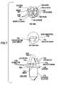
- FIG. 7is a drawing showing a typical embodiment of a universal LED illumination device to retrofit an incandescent lightbulb application.
- a set of LEDs 702is mounted in a triangular pattern to a wafer PC board 704 in either a series or parallel configuration such that the LEDs 702 will project light outward and approximately perpendicular to the top surface of the PC board 704 .
- the LEDs 702are mounted to the PC board 704 by an anode 726 and cathode 728 attachments for each LED 702 on the top surface.
- the converter and logic circuit 706can be mounted on either or both sides of the wafer PC board 704 and are shown in FIG. 7 on the bottom surface.
- LEDs 702 and associated converter and logic circuit 706are connected to a 3-pin connector 712 that facilitates an easy connection to a standard bulb base 716 .
- This connectionis made from each LED through to a single anode 726 connector located in the center of the 3-pin connector 712 , and two cathode 728 connectors that have been bifurcated from each LED 702 and placed lateral to the anode 726 .
- This cathode geometryallows the LED and circuitry module to be placed into connection in either left or right orientation within the 3-pin connector 712 .
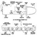
- FIG. 8is a drawing showing a typical embodiment of a universal LED illumination device to retrofit a halogen lightbulb application.
- a group of LEDs 802is mounted to a PC board 804 such that the LEDs 802 will project light outward and perpendicular to the top surface of the PC board 804 to produce an LED halogen replacement bulb 800 .
- the converter and logic circuit 808can be mounted on either or both sides of the wafer PC board 804 and are shown in FIG. 8 on the top surface.
- This top surfacecan be coated with a reflective surface 812 to increase light output intensity by reflecting light otherwise lost and enhance heat dissipation of the LEDs and circuitry.
- LEDs 802 and associated converter and logic circuit 808are made to connect employing “bump ends” 806 that adapt the PC board to fit and electrically connect within halogen bulb fixtures.
- the large area of PC board 804 spaceadditionally allows for additional circuitry 810 to be readily added to either side of the described embodiment.
- FIG. 9is a drawing showing a typical embodiment of a universal LED illumination device to retrofit a focused beam incandescent flashlight application.
- a reflective parabolic reflectoris an integral part of the product's feature set.
- the reflective reflectorcan be moved up and down by rotating a portion of the flashlight's barrel. When this is done, the reflector moves up and down thereby moving the bulb above, through and below the prime focus of the parabolic reflector. This has the effect of focusing or dispersing the light beam to give either a narrow spot or broad beam.
- LEDsusually contain focusing optics, a forward mounting as described above is usually an adequate implementation. However, to take advantage of unique features that may already be present in existing applications, an aftermarket implementation that addresses these specific features and associated needs is necessary.
- a flashlight body 922 containing a standard incandescent bulb 930 with a standard bulb base 928is fixed within a reflective parabolic reflector 920 to reflect and project a beam of light through reflector cover 924 .
- the reflector 920acts to reflect the light emanating from the filament in a standard incandescent bulb 930 to a focused light beam 940 .
- an LED replacement bulbis designed to allow light to emanate from one or more LEDs 902 mounted to a PC board 908 .
- the planar axis of the PC board 908is mounted within a standard bulb base 928 and positioned parallel to a focused beam of light 950 . As illustrated in FIG.
- two LEDs 902are used, one each on either side of a metal core PC board 908 .
- the LEDs 902 in this embodimentsend there light directly towards the surface of the parabolic reflector 910 and project as a focused light beam 950 through reflector cover 914 .
- the LEDs 902are positioned such that they are in the same position relative to the focal point on the parabolic reflector 910 as the filament is in the incandescent bulb 930 it replaces. In this way, the focusing/defocusing feature works as it was intended to since the light is emitted either above or below the prime focus. Hence, both the user and the manufacturer can employ this product and gain the advantages of high efficiency and long life of the LEDs without losing the optical features of the product.
- Either surface of the PC board 908may also contain circuitry and associated electronic components such as a DC-to-DC converter circuit 904 and may contain an electrical connector that mates to a complimentary connector (not shown) mounted within a standard bulb base 928 .
- the bulb base 928 in this exampleis used to make electrical connections to an electrical power source (not shown) and deliver the power to the PC board 908 .
- a metal core PC board 908is shown in this embodiment to demonstrate the ease in which heat dissipation techniques can be adapted to the aforementioned embodiments.
- FIG. 10is a schematic representation of a DC circuit used for a typical embodiment of a universal LED illumination device.
- the circuit of FIG. 3is well suited for constant current operation of low power LEDs where the current required is on the order of 20 mA, the sense resistor R 4 322 in that circuit dissipates power that may be less than optimal at higher current levels.
- An alternative higher current, high frequency, DC-to-DC converter circuit that generates a constant power output, ideal for higher current applications,is utilized to drive the LED 1002 in the disclosed embodiment illustrated in FIG. 10 .
- a positive voltage sourceis introduced at +V in 1012 and branched to an inductor L 1 1020 and to inputs V CC 1024 of an IC driver circuit U 1 1004 (i.e., Zetex ZXSC310).
- the solid-state driver circuit 1004regulates the input voltage V CC 1024 to a specified value to achieve a switched output at V Drive 1028 , which in turn drives an external transistor Q 1 1034 .
- the inductor L 1 1020is charged during the ON cycle phase of Q 1 1034 and discharges in the OFF cycle phase to achieve the desired switched voltage output driving a Schottky diode D 1 1006 that in turn drives the anode side 1008 of the output LED 1002 and capacitor C 10 1018 which is terminated to ground.
- This Schottky diode D 1 1006allows the current to flow in only one direction to the anode side 1008 of the LED 1002 via Q 1 1034 .
- the Schottky diode D 1 1006also assures that there is a quantity of rectification of the AC signal flowing through the circuit so that the LED only sees half of the AC cycle, effectively acting as a DC signal.
- Capacitor C 1 1018becomes a charge reservoir, averaging out what would otherwise be a sinusoidally varying voltage with one half of the sine wave missing.
- a low value sensing resistor, R 1 1020is connected to the ON phase of external transistor Q 1 1034 and minimizes power dissipation. The transistor switches ON and allows current to flow through R 1 1020 , where the voltage drop provides the necessary current sense input to the current sense pin 1032 of the IC U 1 1004 .
- the cathode side 1010 of the LED 1002is pass through ground via R- 4 1022 and branched to ground.
- the comparator 1004stops supplying current.
- the current sense pin 1032therefore serves as feedback reference within the driver circuit 1004 , determining the current values by comparing a feedback current to its internal reference and deciding whether more or less charge is needed, thereby regulating the circuit current.
- ⁇ V in 1014 , capacitors C 1 1018 and, resistor R 1 1020 and the ground terminal 1030 of the driver circuit 1004are all terminated to ground.
- FIG. 11is a schematic representation of an AC circuit used for a typical embodiment of a universal LED illumination device.
- FIG. 11illustrates a typical AC circuit suitable for driving a universal LED illumination device.
- a methodcan be used to rectify the AC voltage to produce a DC signal as referred to above.
- circuits that merely rectify the AC voltageare best suited for use with batteries and when the DC voltage available is less than or equal to the operating voltage of the array of one or more LEDs.
- a 14V AC sourceis often used as the power source and is excessive for one or two LEDs.
- an AC voltage regulatormay be used in conjunction with the LED that utilizes the inherent property of rectification of an LED that will generally withstand 5 V in reverse bias.
- An alternating current voltage sourceis introduced to two IC regulator circuits 1104 and 1106 (i.e., National LM317) at V in 1024 and V in 1034 .
- the solid-state regulator circuits 1104 and 1106regulate the positive and negative going potential using the internal voltage reference of the IC and chop the sinusoidal input from, for example 14V peak-to-peak (P-P) to 3.6 V P-P to set the voltage output at V out 1028 and V out 1038 .
- Chopped outputs V out 1028 and V out 1038feed through parallel ladder path, the first rung containing R 1 1120 and R 2 1130 in series, the second rung containing R 3 1140 and R 4 1150 in series, and the third rung containing an LED 1102 .
- the first rungis connected between R 1 1120 and R 2 1130 to a comparator input ADJ 1132 on regulator circuit 1104 and the second rung is connected between R 3 1140 and R 4 1150 to a comparator input ADJ 1142 on regulator circuit 1106 .
- These comparator inputs ADJ 1132 and ADJ 1142are used as a feedback loop to compare the external voltage reference to an internal voltage reference V ref to set the voltage output V out 1028 and V out 1038 .
- the ratio of R 3 /R 4 and R 1 /R 2determine the positive and negative voltage maximum.
- the 14 V AC peak-to-peak signalis reduced to nearly a square wave with a 3.6V P-P max being used drive the LED 1102 , using the LED 1102 to rectify the signal.
- V out +V ref (1.25 V) [1+(R 1 /R 2 )] is the positive going voltage maximum
- V out ⁇V ref (1.25V) [1+(R 3 /R 4 )] is the negative going voltage maximum.
- V outwould be kept within a range well tolerated by the reverse characteristics of the LED 1102 .
Landscapes
- Engineering & Computer Science (AREA)
- Microelectronics & Electronic Packaging (AREA)
- General Engineering & Computer Science (AREA)
- Physics & Mathematics (AREA)
- Optics & Photonics (AREA)
- Circuit Arrangement For Electric Light Sources In General (AREA)
Abstract
Description
Claims (2)
Priority Applications (17)
| Application Number | Priority Date | Filing Date | Title |
|---|---|---|---|
| US10/820,930US7318661B2 (en) | 2003-09-12 | 2004-04-08 | Universal light emitting illumination device and method |
| US11/026,796US7300173B2 (en) | 2004-04-08 | 2004-12-31 | Replacement illumination device for a miniature flashlight bulb |
| US11/831,791US7448770B2 (en) | 2004-04-08 | 2007-07-31 | Replacement illumination device for a miniature flashlight bulb |
| US11/928,752US7777430B2 (en) | 2003-09-12 | 2007-10-30 | Light emitting diode replacement lamp |
| US12/244,645US7699494B2 (en) | 2004-04-08 | 2008-10-02 | Replacement illumination device for a miniature flashlight bulb |
| US12/716,633US8033682B2 (en) | 2004-04-08 | 2010-03-03 | Replacement illumination device for an incandescent lamp |
| US12/834,234US8400081B2 (en) | 2003-09-12 | 2010-07-12 | Light emitting diode replacement lamp |
| US13/225,695US8240873B2 (en) | 2003-09-12 | 2011-09-06 | Universal light emitting diode illumination device and method |
| US13/225,691US8328386B2 (en) | 2003-09-12 | 2011-09-06 | Universal light emitting diode illumination device and method |
| US13/225,688US8328385B2 (en) | 2003-09-12 | 2011-09-06 | Universal light emitting diode illumination device and method |
| US13/545,449US8529088B2 (en) | 2003-09-12 | 2012-07-10 | Universal light emitting diode illumination device and method |
| US13/766,196US8823290B2 (en) | 2003-09-12 | 2013-02-13 | Light emitting diode replacement lamp |
| US13/961,454US9103511B2 (en) | 2003-09-12 | 2013-08-07 | Universal light emitting diode illumination device and method |
| US13/961,498US9057489B2 (en) | 2003-09-12 | 2013-08-07 | Universal light emitting diode illumination device and method |
| US14/184,071US9049768B2 (en) | 2003-09-12 | 2014-02-19 | Light emitting diode replacement lamp |
| US14/700,786US9622316B2 (en) | 2003-09-12 | 2015-04-30 | Light emitting diode replacement lamp |
| US14/711,328US20150241044A1 (en) | 2003-09-12 | 2015-05-13 | Universal light emitting diode illumiation device and method |
Applications Claiming Priority (2)
| Application Number | Priority Date | Filing Date | Title |
|---|---|---|---|
| US50249503P | 2003-09-12 | 2003-09-12 | |
| US10/820,930US7318661B2 (en) | 2003-09-12 | 2004-04-08 | Universal light emitting illumination device and method |
Related Parent Applications (1)
| Application Number | Title | Priority Date | Filing Date |
|---|---|---|---|
| US10/893,727Continuation-In-PartUS7296913B2 (en) | 2003-09-12 | 2004-07-16 | Light emitting diode replacement lamp |
Related Child Applications (3)
| Application Number | Title | Priority Date | Filing Date |
|---|---|---|---|
| US11/026,796Continuation-In-PartUS7300173B2 (en) | 2003-09-12 | 2004-12-31 | Replacement illumination device for a miniature flashlight bulb |
| US11/026,796ContinuationUS7300173B2 (en) | 2003-09-12 | 2004-12-31 | Replacement illumination device for a miniature flashlight bulb |
| US11/928,752Continuation-In-PartUS7777430B2 (en) | 2003-09-12 | 2007-10-30 | Light emitting diode replacement lamp |
Publications (2)
| Publication Number | Publication Date |
|---|---|
| US20050057187A1 US20050057187A1 (en) | 2005-03-17 |
| US7318661B2true US7318661B2 (en) | 2008-01-15 |
Family
ID=34278833
Family Applications (1)
| Application Number | Title | Priority Date | Filing Date |
|---|---|---|---|
| US10/820,930Expired - LifetimeUS7318661B2 (en) | 2003-09-12 | 2004-04-08 | Universal light emitting illumination device and method |
Country Status (1)
| Country | Link |
|---|---|
| US (1) | US7318661B2 (en) |
Cited By (36)
| Publication number | Priority date | Publication date | Assignee | Title |
|---|---|---|---|---|
| US20060082320A1 (en)* | 2004-10-16 | 2006-04-20 | Osram Sylvania Inc. | Lamp with integral voltage converter having phase-controlled dimming circuit containing a voltage controlled resistor |
| US20060139929A1 (en)* | 2004-12-28 | 2006-06-29 | Robert Gordon Industries, Ltd. | Flashing pen stand operatable based upon user interaction |
| US20060255749A1 (en)* | 2005-05-10 | 2006-11-16 | Glassner Alan G | Dedicated LED Airfield System Architectures |
| US20070069161A1 (en)* | 2005-09-14 | 2007-03-29 | Camm David M | Repeatable heat-treating methods and apparatus |
| US20080084690A1 (en)* | 2006-09-19 | 2008-04-10 | Rappl Philip L | Universal walker headlight |
| US20080130288A1 (en)* | 2003-09-12 | 2008-06-05 | Anthony Catalano | Light Emitting Diode Replacement Lamp |
| US20080174247A1 (en)* | 2007-01-24 | 2008-07-24 | Polytronics Technology Corporation | High Power Lamp and LED Device Thereof |
| US20090098764A1 (en)* | 2007-10-12 | 2009-04-16 | The L.D. Kichler Co. | Positionable lighting systems and methods |
| US20090262529A1 (en)* | 2006-04-14 | 2009-10-22 | Dixon Mark E | Illuminator |
| US20090302730A1 (en)* | 2008-06-04 | 2009-12-10 | Carroll David W | Led-based light bulb device |
| US20100027085A1 (en)* | 2008-08-01 | 2010-02-04 | Anthony Catalano | Adjustable Beam Portable Light |
| US20100045198A1 (en)* | 2008-08-21 | 2010-02-25 | George Lee | Led light engine |
| US20100117561A1 (en)* | 2005-05-10 | 2010-05-13 | Alan Glenn Glassner | Dedicated led airfield system architectures |
| US20100225244A1 (en)* | 2009-03-09 | 2010-09-09 | Jeng Hua Liu | LED penlight bulb |
| CN101989817A (en)* | 2009-07-29 | 2011-03-23 | 通用电气公司 | Three-phase LED power supply |
| US20110260647A1 (en)* | 2003-11-04 | 2011-10-27 | Terralux, Inc. | Light emitting diode replacement lamp |
| USD654602S1 (en) | 2011-04-13 | 2012-02-21 | Forever Bulb, Llc | LED-based light |
| USD664684S1 (en) | 2011-09-02 | 2012-07-31 | Forever Bulb, Llc | LED-based light bulb |
| USD664685S1 (en) | 2011-09-07 | 2012-07-31 | Forever Bulb, Llc | LED-based light bulb with power groove |
| US8240873B2 (en) | 2003-09-12 | 2012-08-14 | Terralux, Inc. | Universal light emitting diode illumination device and method |
| US8371722B2 (en) | 2009-11-04 | 2013-02-12 | Forever Bulb, Llc | LED-based light bulb device with Kelvin corrective features |
| USD691290S1 (en) | 2012-01-05 | 2013-10-08 | Forever Bulb, Llc | LED-based light bulb with multiple stems |
| USD700373S1 (en) | 2012-10-11 | 2014-02-25 | Forever Bulb, Llc | LED light bulb |
| US8669709B2 (en) | 2010-08-27 | 2014-03-11 | American Bright Lighting, Inc. | Solid state lighting driver with THDi bypass circuit |
| US8702275B2 (en) | 2003-11-04 | 2014-04-22 | Terralux, Inc. | Light-emitting diode replacement lamp |
| US8746930B2 (en) | 2003-11-04 | 2014-06-10 | Terralux, Inc. | Methods of forming direct and decorative illumination |
| US8870408B2 (en) | 2012-04-02 | 2014-10-28 | Streamlight, Inc. | Portable light and work light adapter therefor |
| US8950898B2 (en) | 2010-11-10 | 2015-02-10 | Terralux, Inc. | Recessed can downlight retrofit illumination device |
| USD737476S1 (en) | 2014-04-29 | 2015-08-25 | Forever Bulb, Llc | Six internal element LED bulb |
| USD737475S1 (en) | 2014-04-29 | 2015-08-25 | Forever Bulb, Llc | Three internal element LED bulb |
| USD739053S1 (en) | 2014-03-10 | 2015-09-15 | Forever Bulb, Llc | LED light bulb |
| USD739054S1 (en) | 2014-03-10 | 2015-09-15 | Forever Bulb, Llc | LED light bulb |
| USD740987S1 (en) | 2012-10-01 | 2015-10-13 | Streamlight, Inc. | Portable light |
| USD745708S1 (en) | 2014-03-11 | 2015-12-15 | Forever Bulb, Llc | LED light bulb |
| US9631789B2 (en) | 2014-03-31 | 2017-04-25 | Terralux, Inc. | Apparatus and method for retrofitting a fluorescent downlight illumination device |
| US9822937B2 (en) | 2014-06-16 | 2017-11-21 | Abl Ip Holding Llc | Light engine retrofit kit and method for installing same |
Families Citing this family (57)
| Publication number | Priority date | Publication date | Assignee | Title |
|---|---|---|---|---|
| EP1767064A2 (en)* | 2004-04-23 | 2007-03-28 | Beeman Holdings, Llc | Lighting fixture adapter |
| US8733966B2 (en)* | 2004-08-20 | 2014-05-27 | Mag Instrument, Inc. | LED flashlight |
| US20080068849A1 (en)* | 2004-10-28 | 2008-03-20 | Polaris Industries Inc. | ATV worklight |
| US7850362B2 (en) | 2004-11-10 | 2010-12-14 | 1 Energy Solutions, Inc. | Removable LED lamp holder with socket |
| US7850361B2 (en)* | 2004-11-10 | 2010-12-14 | 1 Energy Solutions, Inc. | Removable LED lamp holder |
| GB2421633B (en)* | 2004-12-21 | 2007-02-14 | Richard Peter James Barton | Lamp assembly for pulse operation |
| US8016440B2 (en) | 2005-02-14 | 2011-09-13 | 1 Energy Solutions, Inc. | Interchangeable LED bulbs |
| US20070025109A1 (en)* | 2005-07-26 | 2007-02-01 | Yu Jing J | C7, C9 LED bulb and embedded PCB circuit board |
| US7986112B2 (en)* | 2005-09-15 | 2011-07-26 | Mag Instrument, Inc. | Thermally self-stabilizing LED module |
| US7771350B2 (en)* | 2005-10-21 | 2010-08-10 | General Electric Company | Laryngoscope and laryngoscope handle apparatus including an LED and which may include an ergonomic handle |
| US8083393B2 (en) | 2006-02-09 | 2011-12-27 | 1 Energy Solutions, Inc. | Substantially inseparable LED lamp assembly |
| US7192156B1 (en)* | 2006-02-21 | 2007-03-20 | Chih-Wen Hung | Waterproof indicator light |
| US7357534B2 (en)* | 2006-03-31 | 2008-04-15 | Streamlight, Inc. | Flashlight providing thermal protection for electronic elements thereof |
| CA2645231A1 (en) | 2006-05-02 | 2007-11-15 | Superbulbs, Inc. | Heat removal design for led bulbs |
| WO2007130357A2 (en) | 2006-05-02 | 2007-11-15 | Superbulbs, Inc. | Method of light dispersion and preferential scattering of certain wavelengths of light for light-emitting diodes and bulbs constructed therefrom |
| WO2007130358A2 (en) | 2006-05-02 | 2007-11-15 | Superbulbs, Inc. | Plastic led bulb |
| US7883243B2 (en)* | 2006-07-20 | 2011-02-08 | Streamlight, Inc. | LED flashlight and heat sink arrangement |
| US7238061B1 (en)* | 2006-09-18 | 2007-07-03 | Yu-Chu Lin | Vehicle lighting source adapter |
| US7549786B2 (en)* | 2006-12-01 | 2009-06-23 | Cree, Inc. | LED socket and replaceable LED assemblies |
| US7394211B1 (en)* | 2007-01-30 | 2008-07-01 | Laughing Rabbit, Inc. | Step down power management system for LED flashlight |
| US7859196B2 (en) | 2007-04-25 | 2010-12-28 | American Bright Lighting, Inc. | Solid state lighting apparatus |
| US7784993B2 (en)* | 2007-07-13 | 2010-08-31 | 1 Energy Solutions, Inc. | Watertight LED lamp |
| US8439528B2 (en) | 2007-10-03 | 2013-05-14 | Switch Bulb Company, Inc. | Glass LED light bulbs |
| JP2011501464A (en)* | 2007-10-24 | 2011-01-06 | テオス・インコーポレイテッド | Diffuser for LED light source |
| US7883261B2 (en) | 2008-04-08 | 2011-02-08 | 1 Energy Solutions, Inc. | Water-resistant and replaceable LED lamps |
| US8376606B2 (en) | 2008-04-08 | 2013-02-19 | 1 Energy Solutions, Inc. | Water resistant and replaceable LED lamps for light strings |
| WO2009140141A1 (en)* | 2008-05-13 | 2009-11-19 | Express Imaging Systems, Llc | Gas-discharge lamp replacement |
| US9022612B2 (en)* | 2008-08-07 | 2015-05-05 | Mag Instrument, Inc. | LED module |
| US8314564B2 (en) | 2008-11-04 | 2012-11-20 | 1 Energy Solutions, Inc. | Capacitive full-wave circuit for LED light strings |
| US9326346B2 (en) | 2009-01-13 | 2016-04-26 | Terralux, Inc. | Method and device for remote sensing and control of LED lights |
| US8358085B2 (en) | 2009-01-13 | 2013-01-22 | Terralux, Inc. | Method and device for remote sensing and control of LED lights |
| US8169165B2 (en) | 2009-01-14 | 2012-05-01 | Mag Instrument, Inc. | Multi-mode portable lighting device |
| US9247598B2 (en)* | 2009-01-16 | 2016-01-26 | Mag Instrument, Inc. | Portable lighting devices |
| DE102009037249A1 (en)* | 2009-03-18 | 2010-11-11 | Kay Schumann | Flashlight e.g. quartz-halogen-flash light, for light radiator, has printed circuit board assembled with LEDs, where flashlight is covered with shrink film or casting mass for electrical isolation of flashlight excluding sockets |
| CN201391793Y (en) | 2009-04-20 | 2010-01-27 | 喻北京 | Novel heat dissipation structure of LED bulb |
| WO2010127138A2 (en)* | 2009-05-01 | 2010-11-04 | Express Imaging Systems, Llc | Gas-discharge lamp replacement with passive cooling |
| US8836224B2 (en) | 2009-08-26 | 2014-09-16 | 1 Energy Solutions, Inc. | Compact converter plug for LED light strings |
| CA2781077A1 (en) | 2009-11-17 | 2012-06-28 | Terralux, Inc. | Led power-supply detection and control |
| US9200792B2 (en) | 2009-11-24 | 2015-12-01 | Streamlight, Inc. | Portable light having a heat dissipater with an integral cooling device |
| DE102009054519A1 (en) | 2009-12-10 | 2011-06-16 | Osram Gesellschaft mit beschränkter Haftung | Led lamp |
| WO2011163334A1 (en) | 2010-06-22 | 2011-12-29 | Express Imaging Systems, Llc | Solid state lighting device and method employing heat exchanger thermally coupled circuit board |
| US8492977B2 (en)* | 2010-07-23 | 2013-07-23 | Cree, Inc. | Lighting unit using a retro-formed component |
| US20120051048A1 (en)* | 2010-08-31 | 2012-03-01 | U.S. Led, Ltd. | Retrofit for Non-LED Lighting Fixture |
| US10006609B2 (en)* | 2011-04-08 | 2018-06-26 | Litepanels, Ltd. | Plug compatible LED replacement for incandescent light |
| US8591069B2 (en) | 2011-09-21 | 2013-11-26 | Switch Bulb Company, Inc. | LED light bulb with controlled color distribution using quantum dots |
| WO2013090904A1 (en) | 2011-12-16 | 2013-06-20 | Terralux, Inc. | System and methods of applying bleed circuits in led lamps |
| US9265119B2 (en) | 2013-06-17 | 2016-02-16 | Terralux, Inc. | Systems and methods for providing thermal fold-back to LED lights |
| CN103727462A (en)* | 2013-12-31 | 2014-04-16 | 苏州思莱特电子科技有限公司 | Imaging lamp |
| WO2016054085A1 (en) | 2014-09-30 | 2016-04-07 | Express Imaging Systems, Llc | Centralized control of area lighting hours of illumination |
| US9445485B2 (en) | 2014-10-24 | 2016-09-13 | Express Imaging Systems, Llc | Detection and correction of faulty photo controls in outdoor luminaires |
| JP6765241B2 (en)* | 2016-07-13 | 2020-10-07 | 株式会社小糸製作所 | Lighting device for vehicles |
| US10904992B2 (en) | 2017-04-03 | 2021-01-26 | Express Imaging Systems, Llc | Systems and methods for outdoor luminaire wireless control |
| US11375599B2 (en) | 2017-04-03 | 2022-06-28 | Express Imaging Systems, Llc | Systems and methods for outdoor luminaire wireless control |
| US10820428B2 (en)* | 2017-06-28 | 2020-10-27 | The Boeing Company | Attachment apparatus and methods for use |
| US10164374B1 (en) | 2017-10-31 | 2018-12-25 | Express Imaging Systems, Llc | Receptacle sockets for twist-lock connectors |
| DE102018209368B4 (en) | 2018-06-12 | 2020-01-02 | Fraunhofer-Gesellschaft zur Förderung der angewandten Forschung e.V. | Optics for transmitting and / or receiving element, communication module, arrays of communication modules, system of several communication modules and method for producing an optic |
| FR3083418A1 (en)* | 2018-06-28 | 2020-01-03 | Valeo Vision | SYSTEM FOR CONTROLLING THE POWER SUPPLY OF A PIXELLIZED LIGHT SOURCE |
Citations (42)
| Publication number | Priority date | Publication date | Assignee | Title |
|---|---|---|---|---|
| US3795830A (en) | 1972-08-17 | 1974-03-05 | Shelton J | Led slidebase switchboard lamp |
| US4211955A (en) | 1978-03-02 | 1980-07-08 | Ray Stephen W | Solid state lamp |
| US4727289A (en) | 1985-07-22 | 1988-02-23 | Stanley Electric Co., Ltd. | LED lamp |
| US5097180A (en)* | 1990-09-14 | 1992-03-17 | Roger Ignon | Flickering candle lamp |
| US5222800A (en) | 1992-01-28 | 1993-06-29 | The Genlyte Group Incorporated | Recessed lighting fixture |
| US5463280A (en) | 1994-03-03 | 1995-10-31 | National Service Industries, Inc. | Light emitting diode retrofit lamp |
| US5465197A (en)* | 1994-06-07 | 1995-11-07 | Chien; Tseng-Lu | Portable light |
| US5561346A (en) | 1994-08-10 | 1996-10-01 | Byrne; David J. | LED lamp construction |
| US5575459A (en) | 1995-04-27 | 1996-11-19 | Uniglo Canada Inc. | Light emitting diode lamp |
| US5632551A (en) | 1994-07-18 | 1997-05-27 | Grote Industries, Inc. | LED vehicle lamp assembly |
| US5655830A (en) | 1993-12-01 | 1997-08-12 | General Signal Corporation | Lighting device |
| US5663719A (en) | 1993-04-29 | 1997-09-02 | Electro-Tech's | LED traffic signal light with automatic low-line voltage compensating circuit |
| US5850126A (en) | 1997-04-11 | 1998-12-15 | Kanbar; Maurice S. | Screw-in led lamp |
| US5936599A (en) | 1995-01-27 | 1999-08-10 | Reymond; Welles | AC powered light emitting diode array circuits for use in traffic signal displays |
| US5994845A (en) | 1997-04-24 | 1999-11-30 | Ventur Research & Development Inc. | Electrical light socket |
| US6091614A (en) | 1997-12-17 | 2000-07-18 | Ecolux Inc. | Voltage booster for enabling the power factor controller of a LED lamp upon low ac or dc supply |
| US6140776A (en) | 1999-04-06 | 2000-10-31 | Rachwal; Erwin J. | Flashlight |
| US6150771A (en) | 1997-06-11 | 2000-11-21 | Precision Solar Controls Inc. | Circuit for interfacing between a conventional traffic signal conflict monitor and light emitting diodes replacing a conventional incandescent bulb in the signal |
| US6218785B1 (en)* | 1999-03-19 | 2001-04-17 | Incerti & Simonini Di Incerti Edda & C. S.N.C. | Low-tension lighting device |
| US6232784B1 (en) | 1997-09-22 | 2001-05-15 | Richard Dulasky | Circuit continuity tester and method |
| US6234648B1 (en) | 1998-09-28 | 2001-05-22 | U.S. Philips Corporation | Lighting system |
| US6310445B1 (en) | 2000-01-03 | 2001-10-30 | Dialight Corporation | Led indicator disable circuit and led indicator incorporating the led indicator disable circuit |
| US6371636B1 (en)* | 1999-05-24 | 2002-04-16 | Jam Strait, Inc. | LED light module for vehicles |
| US6380865B1 (en) | 1999-04-06 | 2002-04-30 | 911 Emergency Products, Inc. | Replacement led lamp assembly and modulated power intensity for light source |
| US20020141196A1 (en)* | 2001-03-30 | 2002-10-03 | Richard Camarota | Lamp assembly with selectively positionable bulb |
| US6485160B1 (en)* | 2001-06-25 | 2002-11-26 | Gelcore Llc | Led flashlight with lens |
| US6528954B1 (en) | 1997-08-26 | 2003-03-04 | Color Kinetics Incorporated | Smart light bulb |
| US20030067787A1 (en)* | 2001-10-04 | 2003-04-10 | Koito Manufacturing Co., Ltd. | Vehicle lamp |
| US6570505B1 (en) | 1997-12-30 | 2003-05-27 | Gelcore Llc | LED lamp with a fault-indicating impedance-changing circuit |
| US20030112627A1 (en)* | 2000-09-28 | 2003-06-19 | Deese Raymond E. | Flexible sign illumination apparatus, system and method |
| US6644841B2 (en)* | 2002-03-01 | 2003-11-11 | Gelcore Llc | Light emitting diode reflector |
| US20030210552A1 (en)* | 2002-03-13 | 2003-11-13 | Reinhold Barlian | Indicating light |
| US20040070990A1 (en)* | 2002-10-01 | 2004-04-15 | Witold Szypszak | LED illuminator and method of manufacture |
| US6727652B2 (en)* | 2000-12-21 | 2004-04-27 | Gamesman Limited | Lamps |
| US6791283B2 (en) | 2001-09-07 | 2004-09-14 | Opalec | Dual mode regulated light-emitting diode module for flashlights |
| US20040189262A1 (en) | 2003-03-10 | 2004-09-30 | Leddynamics | Circuit devices, circuit devices which include light emitting diodes, assemblies which include such circuit devices, flashlights which include such assemblies, and methods for directly replacing flashlight bulbs |
| US6819056B2 (en)* | 2003-04-15 | 2004-11-16 | Yeoujyi Electronics Co., Ltd. | Color-changing bulb of instrument panel of a vehicle |
| US20050052865A1 (en)* | 2003-09-05 | 2005-03-10 | Guide Corporation | Lamp housing containing an integrated LED support structure |
| US6893140B2 (en) | 2002-12-13 | 2005-05-17 | W. T. Storey, Inc. | Flashlight |
| US6924605B2 (en)* | 2002-11-27 | 2005-08-02 | James K. Chun | Combination voltage detector and LED flashlight |
| US6981784B2 (en)* | 2002-05-30 | 2006-01-03 | Gelcore, Llc | Side projecting LED signal |
| US7008084B2 (en) | 2003-01-03 | 2006-03-07 | Galli Robert D | Lighting head assembly with integrated heat sink |
- 2004
- 2004-04-08USUS10/820,930patent/US7318661B2/ennot_activeExpired - Lifetime
Patent Citations (42)
| Publication number | Priority date | Publication date | Assignee | Title |
|---|---|---|---|---|
| US3795830A (en) | 1972-08-17 | 1974-03-05 | Shelton J | Led slidebase switchboard lamp |
| US4211955A (en) | 1978-03-02 | 1980-07-08 | Ray Stephen W | Solid state lamp |
| US4727289A (en) | 1985-07-22 | 1988-02-23 | Stanley Electric Co., Ltd. | LED lamp |
| US5097180A (en)* | 1990-09-14 | 1992-03-17 | Roger Ignon | Flickering candle lamp |
| US5222800A (en) | 1992-01-28 | 1993-06-29 | The Genlyte Group Incorporated | Recessed lighting fixture |
| US5663719A (en) | 1993-04-29 | 1997-09-02 | Electro-Tech's | LED traffic signal light with automatic low-line voltage compensating circuit |
| US5655830A (en) | 1993-12-01 | 1997-08-12 | General Signal Corporation | Lighting device |
| US5463280A (en) | 1994-03-03 | 1995-10-31 | National Service Industries, Inc. | Light emitting diode retrofit lamp |
| US5465197A (en)* | 1994-06-07 | 1995-11-07 | Chien; Tseng-Lu | Portable light |
| US5632551A (en) | 1994-07-18 | 1997-05-27 | Grote Industries, Inc. | LED vehicle lamp assembly |
| US5561346A (en) | 1994-08-10 | 1996-10-01 | Byrne; David J. | LED lamp construction |
| US5936599A (en) | 1995-01-27 | 1999-08-10 | Reymond; Welles | AC powered light emitting diode array circuits for use in traffic signal displays |
| US5575459A (en) | 1995-04-27 | 1996-11-19 | Uniglo Canada Inc. | Light emitting diode lamp |
| US5850126A (en) | 1997-04-11 | 1998-12-15 | Kanbar; Maurice S. | Screw-in led lamp |
| US5994845A (en) | 1997-04-24 | 1999-11-30 | Ventur Research & Development Inc. | Electrical light socket |
| US6150771A (en) | 1997-06-11 | 2000-11-21 | Precision Solar Controls Inc. | Circuit for interfacing between a conventional traffic signal conflict monitor and light emitting diodes replacing a conventional incandescent bulb in the signal |
| US6528954B1 (en) | 1997-08-26 | 2003-03-04 | Color Kinetics Incorporated | Smart light bulb |
| US6232784B1 (en) | 1997-09-22 | 2001-05-15 | Richard Dulasky | Circuit continuity tester and method |
| US6091614A (en) | 1997-12-17 | 2000-07-18 | Ecolux Inc. | Voltage booster for enabling the power factor controller of a LED lamp upon low ac or dc supply |
| US6570505B1 (en) | 1997-12-30 | 2003-05-27 | Gelcore Llc | LED lamp with a fault-indicating impedance-changing circuit |
| US6234648B1 (en) | 1998-09-28 | 2001-05-22 | U.S. Philips Corporation | Lighting system |
| US6218785B1 (en)* | 1999-03-19 | 2001-04-17 | Incerti & Simonini Di Incerti Edda & C. S.N.C. | Low-tension lighting device |
| US6380865B1 (en) | 1999-04-06 | 2002-04-30 | 911 Emergency Products, Inc. | Replacement led lamp assembly and modulated power intensity for light source |
| US6140776A (en) | 1999-04-06 | 2000-10-31 | Rachwal; Erwin J. | Flashlight |
| US6371636B1 (en)* | 1999-05-24 | 2002-04-16 | Jam Strait, Inc. | LED light module for vehicles |
| US6310445B1 (en) | 2000-01-03 | 2001-10-30 | Dialight Corporation | Led indicator disable circuit and led indicator incorporating the led indicator disable circuit |
| US20030112627A1 (en)* | 2000-09-28 | 2003-06-19 | Deese Raymond E. | Flexible sign illumination apparatus, system and method |
| US6727652B2 (en)* | 2000-12-21 | 2004-04-27 | Gamesman Limited | Lamps |
| US20020141196A1 (en)* | 2001-03-30 | 2002-10-03 | Richard Camarota | Lamp assembly with selectively positionable bulb |
| US6485160B1 (en)* | 2001-06-25 | 2002-11-26 | Gelcore Llc | Led flashlight with lens |
| US6791283B2 (en) | 2001-09-07 | 2004-09-14 | Opalec | Dual mode regulated light-emitting diode module for flashlights |
| US20030067787A1 (en)* | 2001-10-04 | 2003-04-10 | Koito Manufacturing Co., Ltd. | Vehicle lamp |
| US6644841B2 (en)* | 2002-03-01 | 2003-11-11 | Gelcore Llc | Light emitting diode reflector |
| US20030210552A1 (en)* | 2002-03-13 | 2003-11-13 | Reinhold Barlian | Indicating light |
| US6981784B2 (en)* | 2002-05-30 | 2006-01-03 | Gelcore, Llc | Side projecting LED signal |
| US20040070990A1 (en)* | 2002-10-01 | 2004-04-15 | Witold Szypszak | LED illuminator and method of manufacture |
| US6924605B2 (en)* | 2002-11-27 | 2005-08-02 | James K. Chun | Combination voltage detector and LED flashlight |
| US6893140B2 (en) | 2002-12-13 | 2005-05-17 | W. T. Storey, Inc. | Flashlight |
| US7008084B2 (en) | 2003-01-03 | 2006-03-07 | Galli Robert D | Lighting head assembly with integrated heat sink |
| US20040189262A1 (en) | 2003-03-10 | 2004-09-30 | Leddynamics | Circuit devices, circuit devices which include light emitting diodes, assemblies which include such circuit devices, flashlights which include such assemblies, and methods for directly replacing flashlight bulbs |
| US6819056B2 (en)* | 2003-04-15 | 2004-11-16 | Yeoujyi Electronics Co., Ltd. | Color-changing bulb of instrument panel of a vehicle |
| US20050052865A1 (en)* | 2003-09-05 | 2005-03-10 | Guide Corporation | Lamp housing containing an integrated LED support structure |
Cited By (66)
| Publication number | Priority date | Publication date | Assignee | Title |
|---|---|---|---|---|
| US7777430B2 (en) | 2003-09-12 | 2010-08-17 | Terralux, Inc. | Light emitting diode replacement lamp |
| US9057489B2 (en) | 2003-09-12 | 2015-06-16 | Terralux, Inc. | Universal light emitting diode illumination device and method |
| US8328385B2 (en) | 2003-09-12 | 2012-12-11 | Terralux, Inc. | Universal light emitting diode illumination device and method |
| US8400081B2 (en) | 2003-09-12 | 2013-03-19 | Terralux, Inc. | Light emitting diode replacement lamp |
| US8240873B2 (en) | 2003-09-12 | 2012-08-14 | Terralux, Inc. | Universal light emitting diode illumination device and method |
| US20080130288A1 (en)* | 2003-09-12 | 2008-06-05 | Anthony Catalano | Light Emitting Diode Replacement Lamp |
| US8529088B2 (en) | 2003-09-12 | 2013-09-10 | Terralux, Inc. | Universal light emitting diode illumination device and method |
| US9622316B2 (en) | 2003-09-12 | 2017-04-11 | Terralux, Inc. | Light emitting diode replacement lamp |
| US9049768B2 (en) | 2003-09-12 | 2015-06-02 | Terralux, Inc. | Light emitting diode replacement lamp |
| US20100320499A1 (en)* | 2003-09-12 | 2010-12-23 | Terralux, Inc. | Light emitting diode replacement lamp |
| US8328386B2 (en) | 2003-09-12 | 2012-12-11 | Terralux, Inc. | Universal light emitting diode illumination device and method |
| US8823290B2 (en) | 2003-09-12 | 2014-09-02 | Terralux, Inc. | Light emitting diode replacement lamp |
| US9103511B2 (en) | 2003-09-12 | 2015-08-11 | Terralux, Inc. | Universal light emitting diode illumination device and method |
| US8702275B2 (en) | 2003-11-04 | 2014-04-22 | Terralux, Inc. | Light-emitting diode replacement lamp |
| US8746930B2 (en) | 2003-11-04 | 2014-06-10 | Terralux, Inc. | Methods of forming direct and decorative illumination |
| US9429280B2 (en) | 2003-11-04 | 2016-08-30 | Terralux, Inc. | Light emitting diode replacement lamp |
| US20110260647A1 (en)* | 2003-11-04 | 2011-10-27 | Terralux, Inc. | Light emitting diode replacement lamp |
| US8632215B2 (en)* | 2003-11-04 | 2014-01-21 | Terralux, Inc. | Light emitting diode replacement lamp |
| US7839095B2 (en)* | 2004-10-16 | 2010-11-23 | Osram Sylvania Inc. | Lamp with integral voltage converter having phase-controlled dimming circuit containing a voltage controlled resistor |
| US20060082320A1 (en)* | 2004-10-16 | 2006-04-20 | Osram Sylvania Inc. | Lamp with integral voltage converter having phase-controlled dimming circuit containing a voltage controlled resistor |
| US20060139929A1 (en)* | 2004-12-28 | 2006-06-29 | Robert Gordon Industries, Ltd. | Flashing pen stand operatable based upon user interaction |
| US20100117561A1 (en)* | 2005-05-10 | 2010-05-13 | Alan Glenn Glassner | Dedicated led airfield system architectures |
| US7654720B2 (en)* | 2005-05-10 | 2010-02-02 | Adb Airfield Solutions Llc | Dedicated LED airfield system architectures |
| US8629626B2 (en) | 2005-05-10 | 2014-01-14 | Adb Airfield Solutions, Llc | Dedicated LED airfield system architectures |
| US20060255749A1 (en)* | 2005-05-10 | 2006-11-16 | Glassner Alan G | Dedicated LED Airfield System Architectures |
| US9482468B2 (en)* | 2005-09-14 | 2016-11-01 | Mattson Technology, Inc. | Repeatable heat-treating methods and apparatus |
| US20070069161A1 (en)* | 2005-09-14 | 2007-03-29 | Camm David M | Repeatable heat-treating methods and apparatus |
| US20090262529A1 (en)* | 2006-04-14 | 2009-10-22 | Dixon Mark E | Illuminator |
| US20080084690A1 (en)* | 2006-09-19 | 2008-04-10 | Rappl Philip L | Universal walker headlight |
| US20080174247A1 (en)* | 2007-01-24 | 2008-07-24 | Polytronics Technology Corporation | High Power Lamp and LED Device Thereof |
| US7854616B2 (en) | 2007-10-12 | 2010-12-21 | The L.D. Kichler Co. | Positionable lighting systems and methods |
| US8029293B2 (en) | 2007-10-12 | 2011-10-04 | The L.D. Kichler Co. | Positionable lighting systems and methods |
| US20090098764A1 (en)* | 2007-10-12 | 2009-04-16 | The L.D. Kichler Co. | Positionable lighting systems and methods |
| US8167627B1 (en) | 2007-10-12 | 2012-05-01 | The L.D. Kichler Co. | Positionable lighting systems and methods |
| US8860289B2 (en) | 2008-06-04 | 2014-10-14 | Forever Bulb, Llc | LED-based light bulb device |
| US8421322B2 (en) | 2008-06-04 | 2013-04-16 | Forever Bulb, Llc | LED-based light bulb device |
| US20090302730A1 (en)* | 2008-06-04 | 2009-12-10 | Carroll David W | Led-based light bulb device |
| US8013501B2 (en) | 2008-06-04 | 2011-09-06 | Forever Bulb, Llc | LED-based light bulb device |
| US9709221B2 (en) | 2008-06-04 | 2017-07-18 | Forever Bulb, Llc | LED-based light bulb device |
| US20100027085A1 (en)* | 2008-08-01 | 2010-02-04 | Anthony Catalano | Adjustable Beam Portable Light |
| US8297796B2 (en) | 2008-08-01 | 2012-10-30 | Terralux, Inc. | Adjustable beam portable light |
| US20100045198A1 (en)* | 2008-08-21 | 2010-02-25 | George Lee | Led light engine |
| US8283868B2 (en)* | 2008-08-21 | 2012-10-09 | American Bright Lighting, Inc. | LED light engine |
| US20100225244A1 (en)* | 2009-03-09 | 2010-09-09 | Jeng Hua Liu | LED penlight bulb |
| CN101989817A (en)* | 2009-07-29 | 2011-03-23 | 通用电气公司 | Three-phase LED power supply |
| CN101989817B (en)* | 2009-07-29 | 2014-12-03 | 通用电气公司 | Three-phase LED power supply |
| US8371722B2 (en) | 2009-11-04 | 2013-02-12 | Forever Bulb, Llc | LED-based light bulb device with Kelvin corrective features |
| US8669709B2 (en) | 2010-08-27 | 2014-03-11 | American Bright Lighting, Inc. | Solid state lighting driver with THDi bypass circuit |
| US8950898B2 (en) | 2010-11-10 | 2015-02-10 | Terralux, Inc. | Recessed can downlight retrofit illumination device |
| US9447935B2 (en) | 2010-11-10 | 2016-09-20 | Terralux, Inc. | Recessed can downlight retrofit illumination device |
| USD654602S1 (en) | 2011-04-13 | 2012-02-21 | Forever Bulb, Llc | LED-based light |
| USD664684S1 (en) | 2011-09-02 | 2012-07-31 | Forever Bulb, Llc | LED-based light bulb |
| USD664685S1 (en) | 2011-09-07 | 2012-07-31 | Forever Bulb, Llc | LED-based light bulb with power groove |
| USD691290S1 (en) | 2012-01-05 | 2013-10-08 | Forever Bulb, Llc | LED-based light bulb with multiple stems |
| US8870408B2 (en) | 2012-04-02 | 2014-10-28 | Streamlight, Inc. | Portable light and work light adapter therefor |
| USD740987S1 (en) | 2012-10-01 | 2015-10-13 | Streamlight, Inc. | Portable light |
| USD700373S1 (en) | 2012-10-11 | 2014-02-25 | Forever Bulb, Llc | LED light bulb |
| USD706959S1 (en) | 2012-10-11 | 2014-06-10 | Forever Bulb, Llc | LED light bulb |
| USD739054S1 (en) | 2014-03-10 | 2015-09-15 | Forever Bulb, Llc | LED light bulb |
| USD739053S1 (en) | 2014-03-10 | 2015-09-15 | Forever Bulb, Llc | LED light bulb |
| USD745708S1 (en) | 2014-03-11 | 2015-12-15 | Forever Bulb, Llc | LED light bulb |
| US9631789B2 (en) | 2014-03-31 | 2017-04-25 | Terralux, Inc. | Apparatus and method for retrofitting a fluorescent downlight illumination device |
| USD737475S1 (en) | 2014-04-29 | 2015-08-25 | Forever Bulb, Llc | Three internal element LED bulb |
| USD737476S1 (en) | 2014-04-29 | 2015-08-25 | Forever Bulb, Llc | Six internal element LED bulb |
| US9822937B2 (en) | 2014-06-16 | 2017-11-21 | Abl Ip Holding Llc | Light engine retrofit kit and method for installing same |
| US10508777B2 (en) | 2014-06-16 | 2019-12-17 | Abl Ip Holding Llc | Light engine retrofit kit and method for installing same |
Also Published As
| Publication number | Publication date |
|---|---|
| US20050057187A1 (en) | 2005-03-17 |
Similar Documents
| Publication | Publication Date | Title |
|---|---|---|
| US7318661B2 (en) | Universal light emitting illumination device and method | |
| US9103511B2 (en) | Universal light emitting diode illumination device and method | |
| US8598809B2 (en) | White light color changing solid state lighting and methods | |
| US9028086B2 (en) | Light source for illumination apparatus and method of manufacturing the same | |
| JP5558647B1 (en) | Drive circuit, illumination light source, and illumination device | |
| CN102474958B (en) | Led turn-on circuit, lamp, and illumination apparatus | |
| US20110254450A1 (en) | PROCESS AND APPARATUS FOR REPLACING LEDs ON TRAFFIC SIGNS | |
| JP2007048638A (en) | Lighting fixture | |
| US9913330B2 (en) | Solid-state lighting operable with compact fluorescent ballasts and AC mains | |
| RU2619055C2 (en) | Device to improve compatibility of solid-state light sources with intensity control with phase cut-off | |
| US20100296536A1 (en) | Lighting device using a laser diode as a source of light emission | |
| US9370063B2 (en) | LED driving device and lighting device | |
| KR20090107285A (en) | LED lamp | |
| US20210105879A1 (en) | Led filament lamp with multi-path led driver circuit | |
| JP5939774B2 (en) | Straight tube LED lighting device | |
| KR200331747Y1 (en) | Light emitting diodes lamp using power supply | |
| KR200327767Y1 (en) | Light emitting diodes lamp |
Legal Events
| Date | Code | Title | Description |
|---|---|---|---|
| STCF | Information on status: patent grant | Free format text:PATENTED CASE | |
| AS | Assignment | Owner name:TERRALUX, INC., COLORADO Free format text:ASSIGNMENT OF ASSIGNORS INTEREST;ASSIGNORS:CATALANO, ANTHONY;CATALANO, PATRICIA;TECHNOLOGY ASSESSMENT GROUP, INC.;REEL/FRAME:022368/0383 Effective date:20090224 Owner name:TERRALUX, INC.,COLORADO Free format text:ASSIGNMENT OF ASSIGNORS INTEREST;ASSIGNORS:CATALANO, ANTHONY;CATALANO, PATRICIA;TECHNOLOGY ASSESSMENT GROUP, INC.;REEL/FRAME:022368/0383 Effective date:20090224 | |
| AS | Assignment | Owner name:ACCESS VENTURE PARTNERS II, LP, COLORADO Free format text:SECURITY AGREEMENT;ASSIGNOR:TERRALUX, INC.;REEL/FRAME:022368/0766 Effective date:20090224 Owner name:TECHNOLOGY ASSESSMENT GROUP, INC., COLORADO Free format text:SECURITY AGREEMENT;ASSIGNOR:TERRALUX, INC.;REEL/FRAME:022368/0794 Effective date:20090224 Owner name:CATALANO, ANTHONY, COLORADO Free format text:SECURITY AGREEMENT;ASSIGNOR:TERRALUX, INC.;REEL/FRAME:022390/0341 Effective date:20090224 Owner name:CATALANO, PATRICIA, COLORADO Free format text:SECURITY AGREEMENT;ASSIGNOR:TERRALUX, INC.;REEL/FRAME:022390/0341 Effective date:20090224 Owner name:ACCESS VENTURE PARTNERS II, LP,COLORADO Free format text:SECURITY AGREEMENT;ASSIGNOR:TERRALUX, INC.;REEL/FRAME:022368/0766 Effective date:20090224 Owner name:TECHNOLOGY ASSESSMENT GROUP, INC.,COLORADO Free format text:SECURITY AGREEMENT;ASSIGNOR:TERRALUX, INC.;REEL/FRAME:022368/0794 Effective date:20090224 Owner name:CATALANO, ANTHONY,COLORADO Free format text:SECURITY AGREEMENT;ASSIGNOR:TERRALUX, INC.;REEL/FRAME:022390/0341 Effective date:20090224 Owner name:CATALANO, PATRICIA,COLORADO Free format text:SECURITY AGREEMENT;ASSIGNOR:TERRALUX, INC.;REEL/FRAME:022390/0341 Effective date:20090224 | |
| FEPP | Fee payment procedure | Free format text:PAYER NUMBER DE-ASSIGNED (ORIGINAL EVENT CODE: RMPN); ENTITY STATUS OF PATENT OWNER: LARGE ENTITY Free format text:PAYOR NUMBER ASSIGNED (ORIGINAL EVENT CODE: ASPN); ENTITY STATUS OF PATENT OWNER: LARGE ENTITY | |
| FPAY | Fee payment | Year of fee payment:4 | |
| AS | Assignment | Owner name:EMERALD CLEANTECH FUND II LP, CANADA Free format text:SECURITY AGREEMENT;ASSIGNOR:TERRALUX, INC.;REEL/FRAME:026622/0338 Effective date:20110706 | |
| AS | Assignment | Owner name:TERRALUX, INC., COLORADO Free format text:RELEASE BY SECURED PARTY;ASSIGNOR:ACCESS VENTURE PARTNERS II, LP;REEL/FRAME:027734/0754 Effective date:20120215 | |
| FEPP | Fee payment procedure | Free format text:PAYER NUMBER DE-ASSIGNED (ORIGINAL EVENT CODE: RMPN); ENTITY STATUS OF PATENT OWNER: LARGE ENTITY Free format text:PAYOR NUMBER ASSIGNED (ORIGINAL EVENT CODE: ASPN); ENTITY STATUS OF PATENT OWNER: LARGE ENTITY | |
| FPAY | Fee payment | Year of fee payment:8 | |
| AS | Assignment | Owner name:TERRALUX, INC., COLORADO Free format text:RELEASE BY SECURED PARTY;ASSIGNOR:TECHNOLOGY ASSESSMENT GROUP, INC.;REEL/FRAME:037787/0277 Effective date:20160217 Owner name:TERRALUX, INC., COLORADO Free format text:RELEASE BY SECURED PARTY;ASSIGNORS:CATALANO, ANTHONY;CATALANO, PATRICIA;REEL/FRAME:037787/0396 Effective date:20160217 Owner name:TERRALUX, INC., COLORADO Free format text:RELEASE BY SECURED PARTY;ASSIGNOR:EMERALD CLEANTECH FUND II, LP;REEL/FRAME:037787/0511 Effective date:20120215 | |
| AS | Assignment | Owner name:VENTURE LENDING & LEASING VII, INC., CALIFORNIA Free format text:SECURITY INTEREST;ASSIGNOR:TERRALUX, INC.;REEL/FRAME:039291/0308 Effective date:20160707 Owner name:VENTURE LENDING & LEASING VIII, INC., CALIFORNIA Free format text:SECURITY INTEREST;ASSIGNOR:TERRALUX, INC.;REEL/FRAME:039291/0308 Effective date:20160707 | |
| AS | Assignment | Owner name:COMERICA BANK, MICHIGAN Free format text:SECURITY INTEREST;ASSIGNOR:TERRALUX, INC.;REEL/FRAME:039392/0715 Effective date:20160707 | |
| AS | Assignment | Owner name:NEUGEBOREN O'DOWD PC, COLORADO Free format text:SECURITY INTEREST;ASSIGNOR:TERRALUX, INC. D/B/A SIELO, INC.;REEL/FRAME:043747/0262 Effective date:20150901 | |
| AS | Assignment | Owner name:NEUGEBOREN O'DOWD PC, COLORADO Free format text:RELEASE BY SECURED PARTY;ASSIGNOR:TERRALUX, INC.;REEL/FRAME:044878/0226 Effective date:20171121 | |
| AS | Assignment | Owner name:GENERAL LIGHTING COMPANY INC., CONNECTICUT Free format text:ASSIGNMENT OF ASSIGNORS INTEREST;ASSIGNOR:TERRALUX, INC.;REEL/FRAME:045810/0030 Effective date:20171117 | |
| AS | Assignment | Owner name:GENERAL LIGHTING COMPANY INC., CONNECTICUT Free format text:PATENT TRANSFER STATEMENT (AND FORECLOSURE OF SECURITY INTEREST);ASSIGNORS:VENTURE LENDING & LEASING VII, INC.;VENTURE LENDING & LEASING VIII, INC.;REEL/FRAME:045085/0080 Effective date:20171122 | |
| AS | Assignment | Owner name:LEDVANCE LLC, MASSACHUSETTS Free format text:ASSIGNMENT OF ASSIGNORS INTEREST;ASSIGNOR:GENERAL LIGHTING COMPANY INC.;REEL/FRAME:045260/0954 Effective date:20171220 | |
| FEPP | Fee payment procedure | Free format text:ENTITY STATUS SET TO UNDISCOUNTED (ORIGINAL EVENT CODE: BIG.) | |
| MAFP | Maintenance fee payment | Free format text:PAYMENT OF MAINTENANCE FEE, 12TH YEAR, LARGE ENTITY (ORIGINAL EVENT CODE: M1553); ENTITY STATUS OF PATENT OWNER: LARGE ENTITY Year of fee payment:12 |