US7318564B1 - Power line sentry charging - Google Patents
Power line sentry chargingDownload PDFInfo
- Publication number
- US7318564B1 US7318564B1US11/169,260US16926005AUS7318564B1US 7318564 B1US7318564 B1US 7318564B1US 16926005 AUS16926005 AUS 16926005AUS 7318564 B1US7318564 B1US 7318564B1
- Authority
- US
- United States
- Prior art keywords
- aircraft
- transmission line
- energy
- sub
- line conductor
- Prior art date
- Legal status (The legal status is an assumption and is not a legal conclusion. Google has not performed a legal analysis and makes no representation as to the accuracy of the status listed.)
- Active, expires
Links
- 230000005540biological transmissionEffects0.000claimsabstractdescription70
- 239000004020conductorSubstances0.000claimsabstractdescription62
- 230000005291magnetic effectEffects0.000claimsabstractdescription45
- 238000003032molecular dockingMethods0.000claimsabstractdescription9
- 238000003475laminationMethods0.000claimsdescription11
- 238000013459approachMethods0.000claimsdescription7
- 230000033001locomotionEffects0.000claimsdescription4
- 238000005381potential energyMethods0.000claimsdescription2
- 238000004146energy storageMethods0.000abstractdescription3
- 230000006698inductionEffects0.000abstractdescription3
- 239000000725suspensionSubstances0.000abstractdescription2
- 238000005516engineering processMethods0.000description9
- 230000008878couplingEffects0.000description6
- 238000010168coupling processMethods0.000description6
- 238000005859coupling reactionMethods0.000description6
- 230000013011matingEffects0.000description5
- 238000004804windingMethods0.000description5
- 230000001419dependent effectEffects0.000description4
- 230000007246mechanismEffects0.000description4
- 238000000034methodMethods0.000description4
- 230000008901benefitEffects0.000description3
- 230000007423decreaseEffects0.000description3
- 238000010586diagramMethods0.000description3
- 230000000694effectsEffects0.000description3
- 230000001939inductive effectEffects0.000description3
- 238000012360testing methodMethods0.000description3
- -1Nickel Metal HydrideChemical class0.000description2
- 230000006854communicationEffects0.000description2
- 238000004891communicationMethods0.000description2
- 230000004907fluxEffects0.000description2
- 239000000446fuelSubstances0.000description2
- 238000005259measurementMethods0.000description2
- 229910052987metal hydrideInorganic materials0.000description2
- 238000012986modificationMethods0.000description2
- 230000004048modificationEffects0.000description2
- 229910052759nickelInorganic materials0.000description2
- PXHVJJICTQNCMI-UHFFFAOYSA-NnickelSubstances[Ni]PXHVJJICTQNCMI-UHFFFAOYSA-N0.000description2
- 230000008569processEffects0.000description2
- 230000004044responseEffects0.000description2
- CWYNVVGOOAEACU-UHFFFAOYSA-NFe2+Chemical compound[Fe+2]CWYNVVGOOAEACU-UHFFFAOYSA-N0.000description1
- 230000005355Hall effectEffects0.000description1
- WHXSMMKQMYFTQS-UHFFFAOYSA-NLithiumChemical compound[Li]WHXSMMKQMYFTQS-UHFFFAOYSA-N0.000description1
- 229910005813NiMHInorganic materials0.000description1
- 230000001133accelerationEffects0.000description1
- 230000009471actionEffects0.000description1
- 230000007175bidirectional communicationEffects0.000description1
- 230000001413cellular effectEffects0.000description1
- 230000008859changeEffects0.000description1
- 238000012790confirmationMethods0.000description1
- 238000010276constructionMethods0.000description1
- 238000013461designMethods0.000description1
- 230000009189divingEffects0.000description1
- 238000002474experimental methodMethods0.000description1
- 238000000605extractionMethods0.000description1
- 230000001815facial effectEffects0.000description1
- 239000000835fiberSubstances0.000description1
- 230000006870functionEffects0.000description1
- 238000002955isolationMethods0.000description1
- 229910052744lithiumInorganic materials0.000description1
- 230000007774longtermEffects0.000description1
- 230000014759maintenance of locationEffects0.000description1
- 230000003287optical effectEffects0.000description1
- 230000000717retained effectEffects0.000description1
- 230000035945sensitivityEffects0.000description1
- 239000007787solidSubstances0.000description1
- 239000000126substanceSubstances0.000description1
- 230000007704transitionEffects0.000description1
- 210000003462veinAnatomy0.000description1
- 238000001429visible spectrumMethods0.000description1
- 230000000007visual effectEffects0.000description1
- 238000012800visualizationMethods0.000description1
Images
Classifications
- B—PERFORMING OPERATIONS; TRANSPORTING
- B60—VEHICLES IN GENERAL
- B60L—PROPULSION OF ELECTRICALLY-PROPELLED VEHICLES; SUPPLYING ELECTRIC POWER FOR AUXILIARY EQUIPMENT OF ELECTRICALLY-PROPELLED VEHICLES; ELECTRODYNAMIC BRAKE SYSTEMS FOR VEHICLES IN GENERAL; MAGNETIC SUSPENSION OR LEVITATION FOR VEHICLES; MONITORING OPERATING VARIABLES OF ELECTRICALLY-PROPELLED VEHICLES; ELECTRIC SAFETY DEVICES FOR ELECTRICALLY-PROPELLED VEHICLES
- B60L53/00—Methods of charging batteries, specially adapted for electric vehicles; Charging stations or on-board charging equipment therefor; Exchange of energy storage elements in electric vehicles
- B60L53/10—Methods of charging batteries, specially adapted for electric vehicles; Charging stations or on-board charging equipment therefor; Exchange of energy storage elements in electric vehicles characterised by the energy transfer between the charging station and the vehicle
- B60L53/11—DC charging controlled by the charging station, e.g. mode 4
- B—PERFORMING OPERATIONS; TRANSPORTING
- B60—VEHICLES IN GENERAL
- B60L—PROPULSION OF ELECTRICALLY-PROPELLED VEHICLES; SUPPLYING ELECTRIC POWER FOR AUXILIARY EQUIPMENT OF ELECTRICALLY-PROPELLED VEHICLES; ELECTRODYNAMIC BRAKE SYSTEMS FOR VEHICLES IN GENERAL; MAGNETIC SUSPENSION OR LEVITATION FOR VEHICLES; MONITORING OPERATING VARIABLES OF ELECTRICALLY-PROPELLED VEHICLES; ELECTRIC SAFETY DEVICES FOR ELECTRICALLY-PROPELLED VEHICLES
- B60L53/00—Methods of charging batteries, specially adapted for electric vehicles; Charging stations or on-board charging equipment therefor; Exchange of energy storage elements in electric vehicles
- B60L53/80—Exchanging energy storage elements, e.g. removable batteries
- B—PERFORMING OPERATIONS; TRANSPORTING
- B64—AIRCRAFT; AVIATION; COSMONAUTICS
- B64U—UNMANNED AERIAL VEHICLES [UAV]; EQUIPMENT THEREFOR
- B64U50/00—Propulsion; Power supply
- B64U50/30—Supply or distribution of electrical power
- B64U50/37—Charging when not in flight
- B—PERFORMING OPERATIONS; TRANSPORTING
- B60—VEHICLES IN GENERAL
- B60L—PROPULSION OF ELECTRICALLY-PROPELLED VEHICLES; SUPPLYING ELECTRIC POWER FOR AUXILIARY EQUIPMENT OF ELECTRICALLY-PROPELLED VEHICLES; ELECTRODYNAMIC BRAKE SYSTEMS FOR VEHICLES IN GENERAL; MAGNETIC SUSPENSION OR LEVITATION FOR VEHICLES; MONITORING OPERATING VARIABLES OF ELECTRICALLY-PROPELLED VEHICLES; ELECTRIC SAFETY DEVICES FOR ELECTRICALLY-PROPELLED VEHICLES
- B60L2200/00—Type of vehicles
- B60L2200/10—Air crafts
- B—PERFORMING OPERATIONS; TRANSPORTING
- B64—AIRCRAFT; AVIATION; COSMONAUTICS
- B64U—UNMANNED AERIAL VEHICLES [UAV]; EQUIPMENT THEREFOR
- B64U10/00—Type of UAV
- B64U10/25—Fixed-wing aircraft
- B—PERFORMING OPERATIONS; TRANSPORTING
- B64—AIRCRAFT; AVIATION; COSMONAUTICS
- B64U—UNMANNED AERIAL VEHICLES [UAV]; EQUIPMENT THEREFOR
- B64U2101/00—UAVs specially adapted for particular uses or applications
- B64U2101/30—UAVs specially adapted for particular uses or applications for imaging, photography or videography
- B64U2101/31—UAVs specially adapted for particular uses or applications for imaging, photography or videography for surveillance
- B—PERFORMING OPERATIONS; TRANSPORTING
- B64—AIRCRAFT; AVIATION; COSMONAUTICS
- B64U—UNMANNED AERIAL VEHICLES [UAV]; EQUIPMENT THEREFOR
- B64U50/00—Propulsion; Power supply
- B64U50/10—Propulsion
- B64U50/13—Propulsion using external fans or propellers
- B—PERFORMING OPERATIONS; TRANSPORTING
- B64—AIRCRAFT; AVIATION; COSMONAUTICS
- B64U—UNMANNED AERIAL VEHICLES [UAV]; EQUIPMENT THEREFOR
- B64U50/00—Propulsion; Power supply
- B64U50/10—Propulsion
- B64U50/19—Propulsion using electrically powered motors
- Y—GENERAL TAGGING OF NEW TECHNOLOGICAL DEVELOPMENTS; GENERAL TAGGING OF CROSS-SECTIONAL TECHNOLOGIES SPANNING OVER SEVERAL SECTIONS OF THE IPC; TECHNICAL SUBJECTS COVERED BY FORMER USPC CROSS-REFERENCE ART COLLECTIONS [XRACs] AND DIGESTS
- Y02—TECHNOLOGIES OR APPLICATIONS FOR MITIGATION OR ADAPTATION AGAINST CLIMATE CHANGE
- Y02T—CLIMATE CHANGE MITIGATION TECHNOLOGIES RELATED TO TRANSPORTATION
- Y02T10/00—Road transport of goods or passengers
- Y02T10/60—Other road transportation technologies with climate change mitigation effect
- Y02T10/70—Energy storage systems for electromobility, e.g. batteries
- Y—GENERAL TAGGING OF NEW TECHNOLOGICAL DEVELOPMENTS; GENERAL TAGGING OF CROSS-SECTIONAL TECHNOLOGIES SPANNING OVER SEVERAL SECTIONS OF THE IPC; TECHNICAL SUBJECTS COVERED BY FORMER USPC CROSS-REFERENCE ART COLLECTIONS [XRACs] AND DIGESTS
- Y02—TECHNOLOGIES OR APPLICATIONS FOR MITIGATION OR ADAPTATION AGAINST CLIMATE CHANGE
- Y02T—CLIMATE CHANGE MITIGATION TECHNOLOGIES RELATED TO TRANSPORTATION
- Y02T10/00—Road transport of goods or passengers
- Y02T10/60—Other road transportation technologies with climate change mitigation effect
- Y02T10/7072—Electromobility specific charging systems or methods for batteries, ultracapacitors, supercapacitors or double-layer capacitors
- Y—GENERAL TAGGING OF NEW TECHNOLOGICAL DEVELOPMENTS; GENERAL TAGGING OF CROSS-SECTIONAL TECHNOLOGIES SPANNING OVER SEVERAL SECTIONS OF THE IPC; TECHNICAL SUBJECTS COVERED BY FORMER USPC CROSS-REFERENCE ART COLLECTIONS [XRACs] AND DIGESTS
- Y02—TECHNOLOGIES OR APPLICATIONS FOR MITIGATION OR ADAPTATION AGAINST CLIMATE CHANGE
- Y02T—CLIMATE CHANGE MITIGATION TECHNOLOGIES RELATED TO TRANSPORTATION
- Y02T90/00—Enabling technologies or technologies with a potential or indirect contribution to GHG emissions mitigation
- Y02T90/10—Technologies relating to charging of electric vehicles
- Y02T90/12—Electric charging stations
- Y—GENERAL TAGGING OF NEW TECHNOLOGICAL DEVELOPMENTS; GENERAL TAGGING OF CROSS-SECTIONAL TECHNOLOGIES SPANNING OVER SEVERAL SECTIONS OF THE IPC; TECHNICAL SUBJECTS COVERED BY FORMER USPC CROSS-REFERENCE ART COLLECTIONS [XRACs] AND DIGESTS
- Y02—TECHNOLOGIES OR APPLICATIONS FOR MITIGATION OR ADAPTATION AGAINST CLIMATE CHANGE
- Y02T—CLIMATE CHANGE MITIGATION TECHNOLOGIES RELATED TO TRANSPORTATION
- Y02T90/00—Enabling technologies or technologies with a potential or indirect contribution to GHG emissions mitigation
- Y02T90/10—Technologies relating to charging of electric vehicles
- Y02T90/14—Plug-in electric vehicles
Definitions
- This capabilityis of course partly consumed by the time it takes for the silent unmanned aerial vehicle to make a round trip away from and back to a base i.e., half, more or less of the silent unmanned aerial vehicle's energy can be lost on the round trip to and from a base. From a differing perspective, this limited capability additionally means a silent unmanned aerial vehicle dependent military unit must be located sufficiently close to an urban area to make the unmanned aerial vehicle effective as a surveillance tool.
- the present inventionis believed to offer at least a partial solution to these difficulties and to make the silent unmanned aerial vehicle a bit closer to being of practical value especially in a military environment.
- Theoretically silent unmanned aerial vehicle units made with use of the present invention arrangement for acquiring energycan operate in an urban field for an indefinite time interval (i.e., 24/7/365 capability) with infrequent “return-to-base” cycles being required. Most importantly this long term performance is available with use of presently available technology including present day secondary batteries.
- the present inventionprovides a random transmission line electrical current flow based charging for a battery used in a sub human sized surveillance aircraft.
- said locating stepincluding one of transmission line conductor magnetic field sensing and transmission line conductor visual sighting;
- FIG. 1includes the views of FIG. 1 a , FIG. 1 b and FIG. 1 c and shows a silent unmanned aerial vehicle according to the present invention in three different operating modes.
- FIG. 2includes the views of FIG. 2A and FIG. 2B and shows a silent unmanned aerial vehicle of the present invention type in greater detail.
- FIG. 3shows a part of the FIG. 1 and FIG. 2 silent unmanned aerial vehicle in yet greater detail.
- FIG. 4shows details of one arrangement for the magnetic core 202 and the movable jaw portion 204 .
- FIG. 5shows an achieved battery charging history
- FIG. 6shows a block diagram of elements within a surveillance aircraft such as the aircraft 100 .
- FIG. 7shows details of an alternate surveillance aircraft arrangement usable with the invention.
- FIG. 8includes the views of FIG. 8 a , FIG. 8 b and shows details of an energy collection apparatus.
- FIG. 9shows a representative trickle charger circuit usable with rechargeable batteries of the type useful with the present invention.
- a key concept to the present inventionis that “Numerous overhead power transmission lines that frequent most urban areas may be utilized by silent unmanned aerial vehicles to inductively recharge themselves while perched”. Theoretically these “power line-rechargeable” silent unmanned aerial vehicle units should be able to operate out in the urban field for an indefinite amount of time (i.e., 24/7/365 capability) with very infrequent “return-to-base” cycles being required.
- a typical urban military operationmay for example involve launching swarms of present invention silent unmanned aerial vehicles weeks or even months before troops arrive to seek-out and terminate various combatants. For example, Special Operations troops may pre-program these vehicles to fly to local power lines near the urban areas of interest.
- the silent unmanned aerial vehiclesmay simply locate the nearest power line for a temporary recharging. Once recharged, the silent unmanned aerial vehicles can continue their flight towards the urban theater destination. Upon reaching the theater, the silent unmanned aerial vehicles may then fly high above the area to visually, infrared, radar and possibly audibly locate particular targets of interest. Such silent unmanned aerial vehicles can then transmit intelligence-related information, from a comfortable distance, back to a command center. Chemical and biological sensors may also be mounted onboard the aircraft to warn of impending threats.
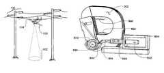
- FIG. 1 in the drawingsshows three events in the operating sequence of an electrical silent unmanned aerial vehicle according to the present invention, these events appear in the FIG. 1 a , FIG. 1 b and FIG. 1 c drawing views.
- FIG. 1 a viewa battery operated multiple propeller driven silent unmanned aerial vehicle 100 has been launched and is conducting an optical surveillance operation over an open terrain area 102 .
- the silent unmanned aerial vehicle 100may be in real-time or store and dump communication with a command center or other user.
- FIG. 1shows three events in the operating sequence of an electrical silent unmanned aerial vehicle according to the present invention, these events appear in the FIG. 1 a , FIG. 1 b and FIG. 1 c drawing views.
- FIG. 1 a viewa battery operated multiple propeller driven silent unmanned aerial vehicle 100 has been launched and is conducting an optical surveillance operation over an open terrain area 102 .
- the silent unmanned aerial vehicle 100may be in real-time or store and dump communication with a command center or other user.
- FIG. 1shows three events in
- the silent unmanned aerial vehicle attachment represented in FIG. 1 bmay result from a flight path that is either generally perpendicular to or tangent to the transmission line conductor 104 as is discussed in detail below.
- FIG. 1 bdrawing the silent unmanned aerial vehicle 100 continues to examine a surveillance area 102 but has now attached itself to one conductor 104 of a convenient electrical energy transmission line 106 where recharging of its electrical battery ensues and the surveillance activity is focused on a selected area 102 adjacent to the transmission line 106 .
- the silent unmanned aerial vehicle attachment represented in FIG. 1 bmay result from a flight path that is either generally perpendicular to or tangent to the transmission line conductor 104 as is discussed in detail below.
- 1 c drawing the silent unmanned aerial vehicle 100has located persons 108 of interest in a particular mission and is maintaining these persons under continuous close surveillance while circling in a suitable flight path and also while communicating the collected video data back to a command center as is implied by the antenna at 110 .
- the silent unmanned aerial vehicle 100has attached itself to one phase conductor 104 of a high-voltage electrical energy transmission line 106 previously located by the silent unmanned aerial vehicle or known to exist from prior knowledge of the area under surveillance.
- the phase conductor 104may be operating at any of the voltages used for electrical energy distribution or transmission, any voltage between 100 volts and 1,000,000 volts for example.
- the electrical current flowing in the conductor 104is in the several tens of amperes to hundreds of amperes range.
- the operating frequency of the transmission line 106is assumed to be of the 50 Hertz or 60 Hertz frequency used in essentially all of the world. Higher frequency transmission lines if they happen to be found by the silent unmanned aerial vehicle are even more advantageous for present energy collection purposes.
- FIG. 2 in the drawingsincludes the views of FIG. 2 a and FIG. 2 b and shows the silent unmanned aerial vehicle 100 itself and the energy collection apparatus 200 for the silent unmanned aerial vehicle in greater detail.
- the silent unmanned aerial vehicleappears in an oblique view wherein a lens array for the video camera included in the airframe appears at 210 in a lower part of the vehicle or aircraft and the energy collection apparatus 200 is shown to be attached to an upper part of the vehicle by way of a mounting bracket appearing at 208 .
- FIG. 2in the drawings includes the views of FIG. 2 a and FIG. 2 b and shows the silent unmanned aerial vehicle 100 itself and the energy collection apparatus 200 for the silent unmanned aerial vehicle in greater detail.
- the silent unmanned aerial vehicleappears in an oblique view wherein a lens array for the video camera included in the airframe appears at 210 in a lower part of the vehicle or aircraft and the energy collection apparatus 200 is shown to be attached to an upper part of the vehicle by way of a mounting bracket appearing at 208 .
- a energy collecting apparatus 200is represented as an open jawed magnetic core 202 having a movable jaw portion 204 closable onto a mating face 216 or on to a magnetic coupler of the core 202 by an actuating rod 214 following engagement with the energy supplying transmission line conductor 104 .
- Engagement of the face 216 with a mating or interleaved face 217 of the movable jaw portion 204 as shown in FIG. 4 or in some other manneris achieved.
- a motor or solenoid mechanism within the airframe of the FIG. 2 aircraftmay be used to move the actuating rod 214 into a closed position upon receipt of a latching command from a ground controller or an internal computer.
- the silent unmanned aerial vehicleIn the closed jaw condition the silent unmanned aerial vehicle is both securely attached to the transmission line conductor 104 and thus precluded from disengagement at the hand of wind bursts or other phenomenon and is also providing of an energy collecting closed magnetic circuit around the transmission line conductor 104 .
- Magnetic circuits having physically open and closed operating positions as shown in FIG. 2 aare known in the art and are to be found for example in the “Tong Test” and “Amprobe” portable current measuring instrument field where such a two position magnetic circuit enables current magnitude measurement to be accomplished without interruption of current flow in the measured circuit.
- the names “Tong Test” and “Amprobe”are believed to be trademarks of The General Electric Company and the Florida-based Advanced Test Products Company.
- One arrangement of the movable yet magnetically integral joints in such a magnetic circuitis shown in greater detail in the FIG. 4 drawing herein, another appears at 800 in the FIG. 8 drawing.
- Magnetic circuits of greater ferrous cross sectional area than those used in measuring instrumentsare of course possible and are preferable in response to the greater energy needs of the present invention.
- a movable magnetic circuit measurement instrument inclusive of a magnetic couplingis shown in the U.S. Pat. No. 2,146,555 identified herewith.
- the silent unmanned aerial vehiclealso appears in an oblique view wherein a lens array for the video camera included in the airframe appears at 210 in a lower part of the aircraft and the energy collection apparatus 200 is shown to be attached to an upper part of the vehicle by way of an upper wing received bracket appearing at 218 .
- the bracket 218 and the energy collection apparatus itselfare rotated by ninety degrees from that shown in the FIG. 2 a drawing. This rotation enables the FIG. 2 b silent unmanned aerial vehicle to engage a transmission line phase conductor 104 during a lengthwise or axial tangency approach to the conductor rather than from the substantially orthogonal approach contemplated for the FIG. 2 a silent unmanned aerial vehicle.
- FIG. 2 a and FIG. 2 b drawingsmay suggest the collection apparatus 200 may be mounted in any rotational position with respect to the airframe 210 or also may disposed in a movable and operator controllable arrangement enabling any angled approach of silent unmanned aerial vehicle to a transmission line conductor.
- the non orthogonal of these possible approachesare of course useful in permitting a more gradual deceleration or acceleration of the silent unmanned aerial vehicle in the transition from flying to parked or docked status and vise versa.
- an additional video camera or a time shared camera input port associated with the camera assembly at 210may be disposed in the tail or other convenient location of the silent unmanned aerial vehicle in order to provide a remote operator with a view of the engaging and disengaging of the silent unmanned aerial vehicle with respect to a transmission line conductor.
- Use of a second camera or coupling between camera locations 210 and 220 using for example fiber optic paths within the silent unmanned aerial vehicleare preferable arrangements for this engaging and disengaging or docking and undocking view from the silent unmanned aerial vehicle.
- the sensing of magnetic field strength surrounding a transmission line conductoras is described in the identified U.S. Pat. Nos.
- Closure of the movable jaw member 204 onto a mating face 216 or a magnetic coupling portion of the core 202 by actuating rod 214may also be viewed critically from a camera location such as that shown at 220 .
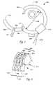
- FIG. 3there is shown the pin 302 by which the movable jaw member 204 is made to be closable onto a mating face 216 of the core 202 by the actuating rod 214 .
- a second rotatable pin member 304provides for similar rotation between the movable jaw 204 and the partially shown actuating rod 214 .
- the FIG. 3 drawingalso shows the winding bundle 212 and leads 300 by which the magnetic flux from the transmission line conductor 104 is enabled to generate electrical energy for use in battery charging and other purposes in the silent unmanned aerial vehicle.
- the transmission line conductor 104is often of the hollow or annular shape found desirable in present day long distance high-voltage transmission lines or alternately may be of the stranded or solid conductor variety.
- conductorsare fabricated to have a circular tongue and groove configuration as is suggested in the FIG. 6 drawing.
- the construction of conductor 104 and the relative size of conductor 104 with respect to the diameter 306 of the core 202are of little if any importance in determining characteristics of the inductive energy collection arrangement of the invention.
- Visualization of a drawing similar to FIG. 3 for the rotated or rotatable energy collection arrangements discussed in connection with FIG. 2 bis believed to be within the skill of persons familiar with this art.
- FIG. 4 in the drawingsshows one arrangement for the core 202 and the movable jaw 204 that may be used in the regions 308 and 310 , the regions of core and movable jaw intersection within the magnetic circuit of the FIG. 3 drawing.
- the core 202 and the movable jaweach be of the laminated nature frequently used in alternating current machinery flux paths in order to limit the energy loss effects of eddy currents induced in these components.
- Lamination thickness used in these componentsis somewhat of a tradeoff between the low losses achieved with thin laminations and the physical rigidity, convenience and maintained joint alignment at 308 for example provided by thicker laminations.
- Thicker laminations representing the core 202are shown at 400 , 402 and 404 in the FIG. 4 drawing where they are interleaved with the also thick laminations 406 , 408 , and 410 that are part of the movable arm 204 in the jaw closed or integral core condition.
- FIG. 4 drawingrepresents the intersection of core and movable arm occurring at 308 in FIG. 3 .
- a larger number of laminations than are represented in FIG. 4 and other drawings hereinmay be desirable for use in the invention in order to generate a greater extraction of energy from the transmission line 104 for present invention usage.
- Other arrangements of the lamination intersections at 308 and 310are of course feasible and are perhaps more practical than that shown in FIG. 3 and FIG. 4 in some instances.
- the core 202 and winding bundle 212are of course in the nature of a current transformer device as is often used in the electrical measuring art for determining the magnitude of transmission line and other alternating currents.
- Such current transformersare available from numerous sources in the electrical art; including for example Ohio Semitronics, Inc. of Hilliard, Ohio and CR Magnetics, Inc. of St. Louis, Mo. The latter manufacturer offers a line of “Split-Core” current transformers identified as the type CR 3110 that are of interest in view of their jointed magnetic circuit and other details appearing relevant to the needs of the present invention.
- These CR Magnetics transformersif not per se usable in the present setting provide a closely related standard item starting point from which an optimum apparatus for use at 200 in the present invention may be achieved.
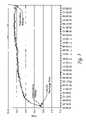
- FIG. 5 in the drawingsshows the results of an experiment in which an 8.4-volt Nickel Metal Hydride battery has been charged by inductive coupling with an average 54-ampere current flowing in a 7.15 kilovolt residential power distribution transmission line, i.e., charged in the manner of the present invention.
- an inductively generated current flow of about 150 milliamperesis used to trickle-charge i.e., is applied to a Nickel Metal Hydride battery of some 900 milliampere-hours electrical capacity and maintained for three and one-half hours in order to increase the battery terminal voltage from an initial largely-discharged value of about 8.1 volts to a final value of about 9.6 volts.
- a simple trickle-charging circuitrywhich is suitable for most NiCad and NiMH battery chemistries, can be utilized to generate the data in FIG. 5 , such a circuit is for example shown in the FIG. 9 drawing herein.
- the power linebasically can supply a sufficient amount of energy over a period of time for any UAV configuration regardless of the size of the battery.
- the amount of energy being transferredis dependent on the amount of current flowing in the transmission line conductor. Assuming the current in the transmission line is held constant, the amount of time required to recharge the battery is proportional to its energy capacity in milliamperes-hours. The larger the milliampere-hour capacity, the longer the UAV may sit and recharge.
- a more advance version of the inventioncan entail replacing the trickle-charging circuit with a fast-charger as recharging circuit.
- Chipssuch as the Maxim MAX1772 multichemistry battery charger can be utilized in this case to recharge, for example, lithium batteries which require a more sophisticated charging scheme than a trickle-charger.
- the FIG. 5 graphis viewed as a confirmation of the overall principle of battery charging by way of inductive coupling from a current-conveying transmission line conductor rather than being an illustration of a fully developed embodiment of the invention. This is true especially since battery voltages of greater magnitude than 9.0 are viewed as being most practical for silent unmanned aerial vehicle propulsion over militarily realistic distances.
- Time for chargingis of course the hidden variable in the charging of the present invention; even though the amounts of energy represented in FIG. 5 are relatively small, even these amounts of energy become significant for present usage when the charging event is extended over a sufficient charging time interval.
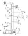
- FIG. 6 in the drawingsshows a coarse general block diagram of electrical components to be included in the silent unmanned aerial vehicle of the present invention; a brief description of components in this diagram not already discussed at length follows.
- the rechargeable battery used to energize the propulsion, control and mission related components of a present invention silent unmanned aerial vehicleappears at 600 in FIG. 6 .
- This batteryis provided with recharging energy by the induction pickup assembly 200 in FIG. 5 and this energy is supplemented by a solar cell array 622 operated by the solar cell controller 624 .
- Energy flow between these recharging sources and the battery 600 and each of the loads shown in FIG. 6is accomplished by a power bus 628 .
- Functional control over each of these load/sourcesis achieved by computer 616 and a computer operated bidirectional communication bus 626 .
- the charged/discharged condition of battery 600is for example sensed by the status circuitry indicated at 629 and communicated to the operator of the vehicle by way of the bus 626 and computer 616 and the radio frequency circuits at 614 .
- This statusis of course important in determining need for a parking and recharging time interval and precluding loss of a totally discharged silent unmanned aerial vehicle.
- Real time sensing of battery charging activityis accomplished by way of the bus 626 and a sensing apparatus 610 ; this precludes attempts to recharge from a transmission line conductor already disabled by military action for example or indicates the need to locate a more active transmission line conductor carrying a greater current.
- On and Off control of the silent unmanned aerial vehicle driving motor 604 as well as speed control of this motoris determined by the computer 616 and the bus 626 by way of an electronic throttle package 606 .
- Low loss switching circuitryin lieu of analog circuits are preferred for use in the electronic throttle package 606 ; this circuitry may also include reverse energy flow provisions in order to take advantage of propeller windmill-generated energy occurring during silent unmanned aerial vehicle diving or landing events.
- Command signals and surveillance data signalsare communicated between the silent unmanned aerial vehicle computer 616 and a ground based station by way of the radio frequency receiver and transmitter 614 and an associated antenna 615 .
- Alternating current energy received from the magnetic induction coupling with a transmission lineis modulated in intensity as well as being rectified by an electronically varied controller 608 ; this control may include either shunt or series control of magnetic circuit output level as is appropriate in view of the saturation and other characteristics of the core of the pickup assembly 200 .
- Opening and closing of the pickup core movable arm 204is achieved in the FIG. 6 system by an actuator 612 controlled from the bus 626 in a manner observable by one of the silent unmanned aerial vehicle cameras, the docking camera 618 .
- Energy transmission line proximity sensingas may be used as an aid to silent unmanned aerial vehicle docking on a transmission line conductor is provided by the bus extension at 613 by which power line proximity data received from the assembly 200 in an open jaw condition is communicated.
- the downward directed data camera 620is used to provide the surveillance data sought by the silent unmanned aerial vehicle; this data may be communicated in real time by way of the bus 626 , the computer 616 and the receiver/transmitter 614 or alternately may be stored in the computer 616 or an auxiliary memory for dumping upon inquiry or at a later convenient time. Orientation of the camera for scanning or field of view enhancement may be used if needed. Orientation of the pickup core movable arm 204 into positions other than a fixed axial or fixed lateral position may be accomplished with another controller apparatus operating from the busses 626 and 628 .
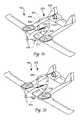
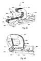
- FIG. 8 in the drawingsshows an alternate and perhaps more real world considered arrangement of the energy collection apparatus 200 usable with the surveillance aircraft of the present invention.
- the energy collection apparatus 200is shown to include a magnetic core portion 202 having the two flat faced surfaces 800 and 802 , a core portion that is closed magnetically by the mating flat faced surfaces 813 and 815 of the movable jaw portion 205 .
- Both the energy collection apparatus 200 and the movable jaw portion 205are made of magnetic laminations in the FIG. 8 drawings and the uppermost of these laminations are provided with longer length to orient the movable arm 205 in an off vertical closed position, as appears in the FIG. 8 b drawing.
- FIG. 8 aalso shows a first torsion spring 810 , a solenoid 804 , a latch member 806 and a second coil spring 808 used during movements of the FIG. 8 a power transmission line conductor trigger 805 and latch 806 .
- a rotational pin for the movable jaw portion 205 , the latch 806 and the springs 808 and 810appears at 832 in the FIG. 8 b drawing.
- the portion of the trigger 805 and latch 806 engaged by the transversely moving incoming energy conductor from which the battery of the aircraft is chargedis designated at 812 in the FIG. 8 drawing.
- the landing aircraftmay for example be moving initially at a velocity of 35 miles per hour or 616 inches per second and may decelerate to zero velocity over a distance of about 0.75 inch while moving the trigger 805 and latch 806 and winding the spring 808 ; this sequence may for example occur in a time near 1.22 milliseconds and achieves closing of the latch 806 and core 202 .
- the aircraftmay rotate around the transmission line conductor however such rotation is acceptable to both aircraft and transmission line under normal conditions.
- spring 808tends to open the latch 806 and to urge the movable jaw 205 toward an open position; the spring 810 tends to urge the movable jaw toward the closed position—by way of the pin 830 .
- the latch 806 and movable jaw 205are retained in the closed condition by way of the radial notch 846 in the latch pivot area; this notch is engaged by the stop element 844 connecting to the solenoid pin 820 as a cam surface of the latch 806 forces the solenoid pin to move rightward in FIG. 8 b against the coil spring 848 during movable jaw 205 closure.
- the pin 820 of solenoid 804is shown to include such a spring 848 and to appear in an extended condition, represented at 843 in the FIG. 8 b drawing. Windings used to control operation of the FIG. 8 solenoid 804 for latch opening are omitted for the sake of clarity in the FIG. 8 drawings.
- opening of latch 806occurs on command of a signal from within the aircraft and involves momentary closure of solenoid 804 at 843 to release the latch 806 , open the movable jaw 205 , unwind the spring 808 and “expel” the energized transmission line conductor from within the core 202 .
- the aircraft 100is moved backward and forced clear of the transmission line conductor and is ready for powered flight again.
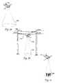
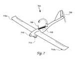
- FIG. 7 in the drawingsshows an alternate airframe arrangement of a power line sentry according to the present invention.
- a single pusher propeller-driven aircraft 700is used to contain the FIG. 6 or other components in an overall arrangement that is believed to be lighter in weight and lower in cost than with the aircraft heretofore shown since there is now only a single motor versus three in FIG. 2 .
- the advantage of the aircraft previously shown in FIG. 2is agility since such a ducted-fan aircraft has much more maneuverability then a single engine aircraft as shown in FIG. 7 . This in turn makes it easier to land or park on a transmission line conductor.
- a second visible spectrum camera 715shown to be mounted in a forward-looking position in the aircraft 700 , and a pair of Hall effect or other Gauss sensors 710 a and 710 b that are disposed in forward looking aircraft positions where they can be used to sense the magnetic fields emanating at 60 Hz or 50 Hz from the transmission line during an approach of the aircraft 700 to a transmission line conductor or other energized magnetic field emitting target element.
- the Gauss sensors 710 a and 710 bare disposed on widely separated parts of the aircraft 700 in order to provide the greatest possible distinction between the two received signals.
- the spit-core current transformer 200is open at this time it is basically configured as a solenoid. As such it can have a dual-use in that it too can be uses as a third magnetic sensor.
- These three magnetic sensorsmoreover may be configured with their sensing axis to be in line with each of the three X, Y, and Z spatial coordinate axis. The outputs from these sensors are fed to the computer 616 through the bus 626 to be used to guide the aircraft 700 in for a landing on the transmission line conductor.
- the FIG. 7 aircraft 700is also provided with a mechanical trigger mechanism, similar to that disclosed in FIG. 8 , and shown at 730 in FIG.
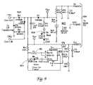
- FIG. 9 in the drawingsshows a representative trickle charger circuit usable with rechargeable batteries of the type employable with the present invention.
- a full-wave bridge rectifier circuit 900is connected to a transmission line conductor pickup coil of the type shown at 200 in FIG. 2 and 200 in FIG. 8 and the output of this circuit applied to a rechargeable battery 902 of the type also used in obtaining the FIG. 5 data.
- Battery and charger condition indicating light emitting diodesare shown at 904 and 906 in the FIG. 9 drawing and these are connected to have unusual responsivity to the indicated battery voltage and charger output voltage.
- a switching circuitis used at U9 in the circuit 906 to ensure sensitivity and accuracy of this light emitting diode 904 indication.
- Remote data indicating linesappear at 904 in FIG. 9 and provide high impedance filtered signals suitable for remotely indicating battery and charger voltages to an operator via the bus 626 in FIG. 6 for example.
Landscapes
- Engineering & Computer Science (AREA)
- Power Engineering (AREA)
- Transportation (AREA)
- Mechanical Engineering (AREA)
- Chemical & Material Sciences (AREA)
- Combustion & Propulsion (AREA)
- Aviation & Aerospace Engineering (AREA)
- Charge And Discharge Circuits For Batteries Or The Like (AREA)
Abstract
Description
This application claims the benefit of U.S. Provisional Patent Application No. 60/617,798, filed Oct. 4, 2004. The contents of this provisional application are hereby incorporated by reference herein.
The present document is somewhat related to the copending and commonly assigned patent document “POWER LINE SENTRY”, Ser. No. 11/169,259. The contents of this somewhat related application are hereby incorporated by reference herein.
The invention described herein may be manufactured and used by or for the Government of the United States for all governmental purposes without the payment of any royalty.
Most modern-day wars are fought in urban environments. Large cities and small towns are the battlegrounds of choice by many present-day enemies. Unfortunately, this environment allows opponents to hide in numerous structures and amongst non-combatant civilians. These environments also provide a much harder and more complicated war to fight than existed in many previous conflicts. In simple terms, one reason for this is that walls tend to get in the way of today's battlefield communications and sensor technologies. One solution to this major new U.S. military problem lies in the time-honored profession of human reconnaissance and surveillance, especially with respect to enemy encounters that involve battles in urban neighborhoods. Unfortunately, it may take years before the United States can develop a capability to successfully gain information regarding this new type of enemy.
Consequently, there is little alternative except to approach a complicated problem with the use of high-technology systems, systems such as satellites and unmanned aerial vehicles, UAV's, used for surveillance purposes. Such systems may include silent, battery-powered, mini and micro-UAVs, i.e., silent unmanned aerial vehicles. Limited battery energy is however currently a major technological hurdle for all-electric silent unmanned aerial vehicles making them unsuitable for most urban battlefield environments. Using today's “off-the-shelf” secondary battery technology, a silent unmanned aerial vehicle (depending on aerodynamic capability and DC motor size) can perform for at most, 60 minutes out in an urban environment. This capability is of course partly consumed by the time it takes for the silent unmanned aerial vehicle to make a round trip away from and back to a base i.e., half, more or less of the silent unmanned aerial vehicle's energy can be lost on the round trip to and from a base. From a differing perspective, this limited capability additionally means a silent unmanned aerial vehicle dependent military unit must be located sufficiently close to an urban area to make the unmanned aerial vehicle effective as a surveillance tool. These considerations presently make current silent unmanned aerial vehicle technologies quite limited for real-time urban military operations.
At first blush one might be tempted to make a silent unmanned aerial vehicle smaller and lighter and thus decrease the level of the required propulsion energy. Unfortunately, however there are very severe physics limitations to the methodology of shrinking an unmanned aerial vehicle both in size and weight. Doing so creates a much more serious mission-capability dilemma in that as the size and weight of the unmanned aerial vehicle decreases, its payload capacity decreases not linearly, but exponentiallyi! (Numbers of this type refer to the list of publications at the end of this specification.) Also, the aeronautical equations dependent on a “Reynolds” number are not usable for small air vehicles of, for example, less than 18 inches in size. Thus use of current-off-the-shelf (COTS) aeronautical CAD software to help design silent unmanned aerial vehicles of these sizes is not possible and one has no recourse but to “guess” a solution and hope it flies. This situation is worsened more by the fact that various aerodynamic instabilities are magnified as the vehicle size decreasesii. This particular problem can be seen in nature while small birds are landing or fighting-off gusts of wind. These birds have to flex and twist their wings and tails to compensate for instantaneous instabilities. Thus it may be appreciated that making electric UAVs smaller presents several technological obstacles.
As a result of these difficulties, existing and pending electric silent unmanned aerial vehicles are useful for only very limited DoD missions. Moreover the personnel that operate and maintain these vehicles must resign themselves to the fact that the battery-power problem is an existing limitation that unfortunately must be factored into the performed mission. Although a new battery technology offering significantly improved energy storage density may ultimately change this picture, it appears likely that this will not occur soon. If laptop computers are used for comparison, in view of their use of similar rechargeable batteries, it may be observed that over the last decade, battery technologies have barely progressed, progressed not nearly as rapidly as other computer related devices such as CPU speed and RAM capacity. In a similar vein of thought the electrically driven automobile is now being approached with use of hybrid electrical motor and fuel driven engine arrangements and with fuel cells but in a large part awaits the availability of rechargeable batteries of suitable energy storage density before becoming widely used.
The present invention is believed to offer at least a partial solution to these difficulties and to make the silent unmanned aerial vehicle a bit closer to being of practical value especially in a military environment. Theoretically silent unmanned aerial vehicle units made with use of the present invention arrangement for acquiring energy can operate in an urban field for an indefinite time interval (i.e., 24/7/365 capability) with infrequent “return-to-base” cycles being required. Most importantly this long term performance is available with use of presently available technology including present day secondary batteries.
The prior art shows numerous uses of inductively coupled electrical energy, energy coupled by way of a magnetic field rather than by electrical circuit continuity. These uses include for example the electric toothbrush, electrical measuring instruments and cellular telephones in the small energy quantity range and extend to submersible vehicles and other propulsion and underwater applications in the larger energy quantity range. These uses and others are included in the several prior art patents identified in the disclosure statement filed with the application of the present patent documents the contents of these issued patents is hereby incorporated by reference herein. None of these energy transmission inventions appear however to have involved an airborne surveillance vehicle or the possibly surreptitious or clandestine acquisition of inductively coupled electrical energy found in the present invention.
The present invention provides a random transmission line electrical current flow based charging for a battery used in a sub human sized surveillance aircraft.
It is therefore an object of the present invention to provide electrically energized silent unmanned aerial vehicle propulsion achievable with present day battery technology and other current technology.
It is another object of the invention to provide unmanned aerial vehicle recharging that is responsive to electrical current flow rather than operating voltage in a transmission line conductor.
It is another object of the invention to provide an aerial vehicle recharging energy source usage that also acts as a physical suspension element for an aircraft vehicle.
It is another object of the invention to provide a battery recharging energy source inclusive of “borrowing” electrical energy from a random convenient transmission line conductor that may be owned by a hostile entity.
It is another object of the invention to provide a battery recharging energy source that includes a physical latch for rigorous and resilient temporary engagement with a transmission line conductor.
It is another object of the invention to provide a clamp-on energy collector usable with a transmission line conductor.
It is another object of the invention to provide an aircraft mountable transmission line energy collector.
It is another object of the invention to provide a laminated alternating current transmission line energy collector that may be operated over a wide range of input current level.
These and other objects of the invention will become apparent as the description of the representative embodiments proceeds.
These and other objects of the invention are achieved by the method of recharging a propulsion battery in a sub human sized aircraft comprising the steps of:
locating a convenient alternating current electrical energy transmission line conductor in a geographic region occupied by said aircraft, said locating step including one of transmission line conductor magnetic field sensing and transmission line conductor visual sighting;
flying said aircraft into a position of physical engagement with said transmission line conductor, said physical engagement including an enclosing of said conductor within an incomplete magnetic circuit carried by said aircraft;
completing said magnetic circuit around said transmission line conductor in response to a command to physically move a magnetic circuit element portion thereof, said completing step including engagement of a controlling magnetic circuit latching mechanism;
collecting battery charging electrical energy from said completed magnetic circuit;
disengaging said magnetic circuit element and said latching mechanism and returning said aircraft to powered flight upon command;
repeating said locating through disengaging sequence of steps with one of said transmission line conductor and a new transmission line conductor upon command and as needed by said battery and said aircraft.
The accompanying drawings incorporated in and forming a part of the specification, illustrate several aspects of the present invention and together with the description serve to explain the principles of the invention. In the drawings:
A key concept to the present invention is that “Numerous overhead power transmission lines that frequent most urban areas may be utilized by silent unmanned aerial vehicles to inductively recharge themselves while perched”. Theoretically these “power line-rechargeable” silent unmanned aerial vehicle units should be able to operate out in the urban field for an indefinite amount of time (i.e., 24/7/365 capability) with very infrequent “return-to-base” cycles being required. A typical urban military operation may for example involve launching swarms of present invention silent unmanned aerial vehicles weeks or even months before troops arrive to seek-out and terminate various combatants. For example, Special Operations troops may pre-program these vehicles to fly to local power lines near the urban areas of interest. If the duration of flight exhausts the battery power, then the silent unmanned aerial vehicles may simply locate the nearest power line for a temporary recharging. Once recharged, the silent unmanned aerial vehicles can continue their flight towards the urban theater destination. Upon reaching the theater, the silent unmanned aerial vehicles may then fly high above the area to visually, infrared, radar and possibly audibly locate particular targets of interest. Such silent unmanned aerial vehicles can then transmit intelligence-related information, from a comfortable distance, back to a command center. Chemical and biological sensors may also be mounted onboard the aircraft to warn of impending threats.
Events shown in theFIG. 1 bdrawing suggest a particular focus of the present invention. In this drawing the silent unmannedaerial vehicle 100 has attached itself to onephase conductor 104 of a high-voltage electricalenergy transmission line 106 previously located by the silent unmanned aerial vehicle or known to exist from prior knowledge of the area under surveillance. Thephase conductor 104 may be operating at any of the voltages used for electrical energy distribution or transmission, any voltage between 100 volts and 1,000,000 volts for example. Preferably however the electrical current flowing in theconductor 104 is in the several tens of amperes to hundreds of amperes range. The operating frequency of thetransmission line 106 is assumed to be of the 50 Hertz or 60 Hertz frequency used in essentially all of the world. Higher frequency transmission lines if they happen to be found by the silent unmanned aerial vehicle are even more advantageous for present energy collection purposes.
A motor or solenoid mechanism within the airframe of theFIG. 2 aircraft may be used to move theactuating rod 214 into a closed position upon receipt of a latching command from a ground controller or an internal computer. In the closed jaw condition the silent unmanned aerial vehicle is both securely attached to thetransmission line conductor 104 and thus precluded from disengagement at the hand of wind bursts or other phenomenon and is also providing of an energy collecting closed magnetic circuit around thetransmission line conductor 104. Significantly, in the absence of another conductor completing an electrical circuit from thetransmission line conductor 104 or from the silent unmannedaerial vehicle 100 to earth etc., there is no transmission line voltage-dependent current flow to cause arcing damage to the silent unmannedaerial vehicle 100 in theFIG. 1 andFIG. 2 suspended condition. This desirable isolation prevails regardless of the 69 kilovolt or other operating potential of thetransmission line conductor 104.
Magnetic circuits having physically open and closed operating positions as shown inFIG. 2 aare known in the art and are to be found for example in the “Tong Test” and “Amprobe” portable current measuring instrument field where such a two position magnetic circuit enables current magnitude measurement to be accomplished without interruption of current flow in the measured circuit. The names “Tong Test” and “Amprobe” are believed to be trademarks of The General Electric Company and the Florida-based Advanced Test Products Company. One arrangement of the movable yet magnetically integral joints in such a magnetic circuit is shown in greater detail in theFIG. 4 drawing herein, another appears at800 in theFIG. 8 drawing. Magnetic circuits of greater ferrous cross sectional area than those used in measuring instruments are of course possible and are preferable in response to the greater energy needs of the present invention. A movable magnetic circuit measurement instrument inclusive of a magnetic coupling is shown in the U.S. Pat. No. 2,146,555 identified herewith.
In theFIG. 2 bdrawing the silent unmanned aerial vehicle also appears in an oblique view wherein a lens array for the video camera included in the airframe appears at210 in a lower part of the aircraft and theenergy collection apparatus 200 is shown to be attached to an upper part of the vehicle by way of an upper wing received bracket appearing at218. Notably in theFIG. 2 bdrawing thebracket 218 and the energy collection apparatus itself are rotated by ninety degrees from that shown in theFIG. 2 adrawing. This rotation enables theFIG. 2 bsilent unmanned aerial vehicle to engage a transmissionline phase conductor 104 during a lengthwise or axial tangency approach to the conductor rather than from the substantially orthogonal approach contemplated for theFIG. 2 asilent unmanned aerial vehicle. As the combination of theFIG. 2 aandFIG. 2 bdrawings may suggest thecollection apparatus 200 may be mounted in any rotational position with respect to theairframe 210 or also may disposed in a movable and operator controllable arrangement enabling any angled approach of silent unmanned aerial vehicle to a transmission line conductor. The non orthogonal of these possible approaches are of course useful in permitting a more gradual deceleration or acceleration of the silent unmanned aerial vehicle in the transition from flying to parked or docked status and vise versa.
As is represented at220 in theFIG. 2 aandFIG. 2 bdrawings an additional video camera or a time shared camera input port associated with the camera assembly at210 may be disposed in the tail or other convenient location of the silent unmanned aerial vehicle in order to provide a remote operator with a view of the engaging and disengaging of the silent unmanned aerial vehicle with respect to a transmission line conductor. Use of a second camera or coupling betweencamera locations movable jaw member 204 onto amating face 216 or a magnetic coupling portion of thecore 202 by actuatingrod 214 may also be viewed critically from a camera location such as that shown at220.
InFIG. 3 there is shown thepin 302 by which themovable jaw member 204 is made to be closable onto amating face 216 of thecore 202 by theactuating rod 214. A secondrotatable pin member 304 provides for similar rotation between themovable jaw 204 and the partially shown actuatingrod 214. TheFIG. 3 drawing also shows the windingbundle 212 and leads300 by which the magnetic flux from thetransmission line conductor 104 is enabled to generate electrical energy for use in battery charging and other purposes in the silent unmanned aerial vehicle. As indicated in theFIG. 3 drawing thetransmission line conductor 104 is often of the hollow or annular shape found desirable in present day long distance high-voltage transmission lines or alternately may be of the stranded or solid conductor variety. Often such conductors are fabricated to have a circular tongue and groove configuration as is suggested in theFIG. 6 drawing. The construction ofconductor 104 and the relative size ofconductor 104 with respect to thediameter 306 of thecore 202 are of little if any importance in determining characteristics of the inductive energy collection arrangement of the invention. Visualization of a drawing similar toFIG. 3 for the rotated or rotatable energy collection arrangements discussed in connection withFIG. 2 bis believed to be within the skill of persons familiar with this art.
Onceconductor 104 becomes enclosed by thecore 202 and the closedmovable jaw 204 this entire configuration becomes an electromagnet as long as there is current flowing in thetransmission line conductor 104. The problem here is that the two parts of thecore 202 now “attract” each other. This is a significant consideration during the delatching process. We find a simple solution to this consideration exists in the form of shorting the twowires 300 together; this stops the attracting fields and allows disengagement. A simple relay or MOSFET can be used to achieve this function in a practical embodiment of the invention. A resistor in series may help dissipate the heat generated.FIG. 4 in the drawings shows one arrangement for thecore 202 and themovable jaw 204 that may be used in theregions FIG. 3 drawing. As indicated in theFIG. 4 drawing it is preferable that thecore 202 and the movable jaw each be of the laminated nature frequently used in alternating current machinery flux paths in order to limit the energy loss effects of eddy currents induced in these components. Lamination thickness used in these components is somewhat of a tradeoff between the low losses achieved with thin laminations and the physical rigidity, convenience and maintained joint alignment at308 for example provided by thicker laminations. Thicker laminations representing thecore 202 are shown at400,402 and404 in theFIG. 4 drawing where they are interleaved with the alsothick laminations movable arm 204 in the jaw closed or integral core condition.
As implied by the illustrated curvature of the laminations shown inFIG. 4 , theFIG. 4 drawing represents the intersection of core and movable arm occurring at308 inFIG. 3 . A larger number of laminations than are represented inFIG. 4 and other drawings herein may be desirable for use in the invention in order to generate a greater extraction of energy from thetransmission line 104 for present invention usage. Other arrangements of the lamination intersections at308 and310 are of course feasible and are perhaps more practical than that shown inFIG. 3 andFIG. 4 in some instances. The use of machined surfaces on thecore 202, in thefacial area 216, and the use of similar and complementing machined surfaces on themovable member 204 together with a sliding motion engagement of machined surfaces by themovable arm 214 are particularly attractive alternatives to theFIG. 4 arrangement of these components.
Thecore 202 and windingbundle 212 are of course in the nature of a current transformer device as is often used in the electrical measuring art for determining the magnitude of transmission line and other alternating currents. Such current transformers are available from numerous sources in the electrical art; including for example Ohio Semitronics, Inc. of Hilliard, Ohio and CR Magnetics, Inc. of St. Louis, Mo. The latter manufacturer offers a line of “Split-Core” current transformers identified as the type CR 3110 that are of interest in view of their jointed magnetic circuit and other details appearing relevant to the needs of the present invention. These CR Magnetics transformers if not per se usable in the present setting provide a closely related standard item starting point from which an optimum apparatus for use at200 in the present invention may be achieved.
A more advance version of the invention can entail replacing the trickle-charging circuit with a fast-charger as recharging circuit. Chips such as the Maxim MAX1772 multichemistry battery charger can be utilized in this case to recharge, for example, lithium batteries which require a more sophisticated charging scheme than a trickle-charger. TheFIG. 5 graph is viewed as a confirmation of the overall principle of battery charging by way of inductive coupling from a current-conveying transmission line conductor rather than being an illustration of a fully developed embodiment of the invention. This is true especially since battery voltages of greater magnitude than 9.0 are viewed as being most practical for silent unmanned aerial vehicle propulsion over militarily realistic distances. Time for charging is of course the hidden variable in the charging of the present invention; even though the amounts of energy represented inFIG. 5 are relatively small, even these amounts of energy become significant for present usage when the charging event is extended over a sufficient charging time interval.
On and Off control of the silent unmanned aerialvehicle driving motor 604 as well as speed control of this motor is determined by thecomputer 616 and thebus 626 by way of anelectronic throttle package 606. Low loss switching circuitry in lieu of analog circuits are preferred for use in theelectronic throttle package 606; this circuitry may also include reverse energy flow provisions in order to take advantage of propeller windmill-generated energy occurring during silent unmanned aerial vehicle diving or landing events. Command signals and surveillance data signals are communicated between the silent unmannedaerial vehicle computer 616 and a ground based station by way of the radio frequency receiver andtransmitter 614 and an associatedantenna 615. Alternating current energy received from the magnetic induction coupling with a transmission line is modulated in intensity as well as being rectified by an electronicallyvaried controller 608; this control may include either shunt or series control of magnetic circuit output level as is appropriate in view of the saturation and other characteristics of the core of thepickup assembly 200.
Opening and closing of the pickup coremovable arm 204 is achieved in theFIG. 6 system by anactuator 612 controlled from thebus 626 in a manner observable by one of the silent unmanned aerial vehicle cameras, thedocking camera 618. Energy transmission line proximity sensing as may be used as an aid to silent unmanned aerial vehicle docking on a transmission line conductor is provided by the bus extension at613 by which power line proximity data received from theassembly 200 in an open jaw condition is communicated. The downward directeddata camera 620 is used to provide the surveillance data sought by the silent unmanned aerial vehicle; this data may be communicated in real time by way of thebus 626, thecomputer 616 and the receiver/transmitter 614 or alternately may be stored in thecomputer 616 or an auxiliary memory for dumping upon inquiry or at a later convenient time. Orientation of the camera for scanning or field of view enhancement may be used if needed. Orientation of the pickup coremovable arm 204 into positions other than a fixed axial or fixed lateral position may be accomplished with another controller apparatus operating from thebusses
The portion of thetrigger 805 and latch806 engaged by the transversely moving incoming energy conductor from which the battery of the aircraft is charged is designated at812 in theFIG. 8 drawing. During this movement the landing aircraft may for example be moving initially at a velocity of 35 miles per hour or 616 inches per second and may decelerate to zero velocity over a distance of about 0.75 inch while moving thetrigger 805 and latch806 and winding thespring 808; this sequence may for example occur in a time near 1.22 milliseconds and achieves closing of thelatch 806 andcore 202. During such deceleration the aircraft may rotate around the transmission line conductor however such rotation is acceptable to both aircraft and transmission line under normal conditions. In thewound condition spring 808 tends to open thelatch 806 and to urge themovable jaw 205 toward an open position; thespring 810 tends to urge the movable jaw toward the closed position—by way of thepin 830.
Thelatch 806 andmovable jaw 205 are retained in the closed condition by way of theradial notch 846 in the latch pivot area; this notch is engaged by thestop element 844 connecting to thesolenoid pin 820 as a cam surface of thelatch 806 forces the solenoid pin to move rightward inFIG. 8 bagainst thecoil spring 848 duringmovable jaw 205 closure. Thepin 820 ofsolenoid 804 is shown to include such aspring 848 and to appear in an extended condition, represented at843 in theFIG. 8 bdrawing. Windings used to control operation of theFIG. 8 solenoid 804 for latch opening are omitted for the sake of clarity in theFIG. 8 drawings. Similarly windings used for energy collection during the recharging process are also omitted for the sake of clarity on thecore portion 202 inFIG. 8 aandFIG. 8 b. Opening oflatch 806 occurs on command of a signal from within the aircraft and involves momentary closure ofsolenoid 804 at843 to release thelatch 806, open themovable jaw 205, unwind thespring 808 and “expel” the energized transmission line conductor from within thecore 202. As a result of this expulsion theaircraft 100 is moved backward and forced clear of the transmission line conductor and is ready for powered flight again.
Additionally included in theFIG. 7 power line sentry 700 are a secondvisible spectrum camera 715, shown to be mounted in a forward-looking position in theaircraft 700, and a pair of Hall effect orother Gauss sensors aircraft 700 to a transmission line conductor or other energized magnetic field emitting target element. Notably theGauss sensors aircraft 700 in order to provide the greatest possible distinction between the two received signals. Notably in addition, since the spit-corecurrent transformer 200 is open at this time it is basically configured as a solenoid. As such it can have a dual-use in that it too can be uses as a third magnetic sensor. These three magnetic sensors moreover may be configured with their sensing axis to be in line with each of the three X, Y, and Z spatial coordinate axis. The outputs from these sensors are fed to thecomputer 616 through thebus 626 to be used to guide theaircraft 700 in for a landing on the transmission line conductor. TheFIG. 7 aircraft 700 is also provided with a mechanical trigger mechanism, similar to that disclosed inFIG. 8 , and shown at730 inFIG. 7 , in which kinetic energy developed at the time ofaircraft 700 docking on a transmission line conductor may be converted into potential energy for storage and use during disengagement of theaircraft 700 from its docked condition and returning to a flight supported condition. This stored energy can supply a helpful initial sendoff push for theaircraft 700. The previously described infrared camera is represented in the downward looking position at210 in theFIG. 7 drawing.
The foregoing description of the preferred embodiment has been presented for purposes of illustration and description. It is not intended to be exhaustive or to limit the invention to the precise form disclosed. Obvious modifications or variations are possible in light of the above teachings. The embodiment was chosen and described to provide the best illustration of the principles of the invention and its practical application to thereby enable one of ordinary skill in the art to utilize the inventions in various embodiments and with various modifications as are suited to the particular scope of the invention as determined by the appended claims when interpreted in accordance with the breadth to which they are fairly, legally and equitably entitled.
Claims (11)
1. A sub-human sized aircraft comprising: an electrical apparatus for collecting aircraft propulsion electrical energy from an opportune energize alternating current transmission line conductor, said electrical apparatus comprising:
a magnetic core member having a movable link portion disposable in a magnetically open core position and a magnetically closed core position, said magnetic core member being mounted on a salient portion of said aircraft in a position of convenient opened core position engagement with said transmission line conductor during an aircraft approach and parking sequence;
a movable core link operating apparatus connected with said magnetic core movable link portion and responsive to an open core and a closed core electrical control signal;
a sensor apparatus received on said aircraft for determining proximity of said aircraft to said energized alternating current transmission line conductor; and
a control apparatus responsive to said sensor apparatus and enabling movement of said core link operating apparatus attending transmission line docking and undocking maneuvers.
2. The sub-human sized aircraft ofclaim 1 wherein said collected electrical energy is magnitude responsive to an electrical current flow magnitude in said opportune energized alternating current transmission line conductor.
3. The sub-human sized aircraft ofclaim 1 wherein said magnetic core member and said movable link portion each include flat faced abutment portions.
4. The sub-human sized aircraft ofclaim 1 wherein said magnetic core member and said movable link portion each include interleaved lamination movable magnetic circuit portions.
5. The sub-human sized aircraft ofclaim 1 wherein said opportune energized alternating current transmission line conductor is located in hostile territory.
6. The sub-human sized aircraft ofclaim 1 wherein said control apparatus is responsive to one of a signal originating within said aircraft and a ground based control signal.
7. The sub-human sized aircraft ofclaim 1 wherein said movable core link operating apparatus includes an electrical solenoid element.
8. The sub-human sized aircraft ofclaim 1 wherein said movable core link operating apparatus includes a docking and undocking energy exchanging spring loaded latch apparatus.
9. The sub-human sized aircraft ofclaim 1 wherein said sensor apparatus received on said aircraft for determining proximity of said aircraft to said energized alternating current transmission line conductor includes one of a camera member and a Gauss sensor member.
10. The sub-human sized aircraft ofclaim 1 wherein said sensor apparatus received on said aircraft for determining proximity of said aircraft to said energized alternating current transmission line conductor includes a kinetic energy to potential energy converting resilient member.
11. The sub-human sized aircraft ofclaim 1 wherein said electrical apparatus further includes a rechargeable electrical battery energized by said aircraft propulsion electrical energy.
Priority Applications (2)
| Application Number | Priority Date | Filing Date | Title |
|---|---|---|---|
| US11/169,260US7318564B1 (en) | 2004-10-04 | 2005-06-24 | Power line sentry charging |
| US11/344,631US7543780B1 (en) | 2004-10-04 | 2006-01-13 | Unmanned air vehicle transmission line docking surveillance |
Applications Claiming Priority (2)
| Application Number | Priority Date | Filing Date | Title |
|---|---|---|---|
| US61779804P | 2004-10-04 | 2004-10-04 | |
| US11/169,260US7318564B1 (en) | 2004-10-04 | 2005-06-24 | Power line sentry charging |
Related Child Applications (1)
| Application Number | Title | Priority Date | Filing Date |
|---|---|---|---|
| US11/344,631Continuation-In-PartUS7543780B1 (en) | 2004-10-04 | 2006-01-13 | Unmanned air vehicle transmission line docking surveillance |
Publications (1)
| Publication Number | Publication Date |
|---|---|
| US7318564B1true US7318564B1 (en) | 2008-01-15 |
Family
ID=38920976
Family Applications (1)
| Application Number | Title | Priority Date | Filing Date |
|---|---|---|---|
| US11/169,260Active2025-11-18US7318564B1 (en) | 2004-10-04 | 2005-06-24 | Power line sentry charging |
Country Status (1)
| Country | Link |
|---|---|
| US (1) | US7318564B1 (en) |
Cited By (215)
| Publication number | Priority date | Publication date | Assignee | Title |
|---|---|---|---|---|
| US7714536B1 (en)* | 2007-04-05 | 2010-05-11 | The United States Of America As Represented By The Secretary Of The Navy | Battery charging arrangement for unmanned aerial vehicle utilizing the electromagnetic field associated with utility power lines to generate power to inductively charge energy supplies |
| US20120086804A1 (en)* | 2010-04-19 | 2012-04-12 | Sony Corporation | Imaging apparatus and method of controlling the same |
| US8167234B1 (en)* | 2010-03-21 | 2012-05-01 | Michael Moore | Insect-like micro air vehicle having perching, energy scavenging, crawling, and offensive payload capabilities |
| US20130175382A1 (en)* | 2008-10-29 | 2013-07-11 | Rinaldo Brutoco | System, method and apparatus for widespread commercialization of hydrogen as a carbon-free alternative fuel source |
| US8511606B1 (en) | 2009-12-09 | 2013-08-20 | The Boeing Company | Unmanned aerial vehicle base station |
| US20130248648A1 (en)* | 2012-03-21 | 2013-09-26 | Sikorsky Aircraft Corporation | Portable Control System For Rotary-Wing Aircraft Load Management |
| DE202013009297U1 (en)* | 2013-10-22 | 2013-11-15 | Jonas Lewandrowski | Unmanned aerial vehicle (UAV) with electric drive and a device for inductive charging |
| FR2996822A1 (en)* | 2012-10-12 | 2014-04-18 | Inst Superieur De L Aeronautique Et De L Espace | TELE-OPERE DRONE COMPRISING A MEANS FOR FIXING TO A SURFACE |
| US8767071B1 (en)* | 2011-03-03 | 2014-07-01 | The United States Of America As Represented By The Secretary Of The Air Force | High voltage power line multi-sensor system |
| US8874283B1 (en) | 2012-12-04 | 2014-10-28 | United Dynamics Advanced Technologies Corporation | Drone for inspection of enclosed space and method thereof |
| JP2015017887A (en)* | 2013-07-11 | 2015-01-29 | 中国電力株式会社 | Accident point survey device |
| DE102014001702A1 (en)* | 2014-02-08 | 2015-08-13 | Mbda Deutschland Gmbh | Unmanned small aircraft and method for landing a small aircraft |
| DE102014005838A1 (en)* | 2014-04-19 | 2015-10-22 | Mbda Deutschland Gmbh | Unmanned small aircraft and method for landing a small aircraft |
| JP2015196420A (en)* | 2014-03-31 | 2015-11-09 | 三菱重工業株式会社 | Aircraft leg structure and method of operating aircraft leg structure |
| US20160137311A1 (en)* | 2013-03-14 | 2016-05-19 | Aurora Flight Sciences Corporation | Aerial system and vehicle for continuous operation |
| JP2016107843A (en)* | 2014-12-08 | 2016-06-20 | Jfeスチール株式会社 | Three-dimensional shape measurement method and device using multicopter |
| US9544006B2 (en) | 2014-11-20 | 2017-01-10 | At&T Intellectual Property I, L.P. | Transmission device with mode division multiplexing and methods for use therewith |
| US20170015415A1 (en)* | 2015-07-15 | 2017-01-19 | Elwha Llc | System and method for operating unmanned aircraft |
| US20170025744A1 (en)* | 2015-07-20 | 2017-01-26 | Qualcomm Incorporated | Motor feed antenna for vehicle |
| US20170032686A1 (en)* | 2015-07-30 | 2017-02-02 | Airbus (Sas) | Drone pad station and managing set of such a drone pad station |
| CN106477056A (en)* | 2015-08-31 | 2017-03-08 | 李烨 | Unmanned vehicle with hoistable platform |
| US9608740B2 (en) | 2015-07-15 | 2017-03-28 | At&T Intellectual Property I, L.P. | Method and apparatus for launching a wave mode that mitigates interference |
| US9608692B2 (en) | 2015-06-11 | 2017-03-28 | At&T Intellectual Property I, L.P. | Repeater and methods for use therewith |
| US9615269B2 (en) | 2014-10-02 | 2017-04-04 | At&T Intellectual Property I, L.P. | Method and apparatus that provides fault tolerance in a communication network |
| US9628116B2 (en) | 2015-07-14 | 2017-04-18 | At&T Intellectual Property I, L.P. | Apparatus and methods for transmitting wireless signals |
| US9627768B2 (en) | 2014-10-21 | 2017-04-18 | At&T Intellectual Property I, L.P. | Guided-wave transmission device with non-fundamental mode propagation and methods for use therewith |
| US9640850B2 (en) | 2015-06-25 | 2017-05-02 | At&T Intellectual Property I, L.P. | Methods and apparatus for inducing a non-fundamental wave mode on a transmission medium |
| US9654173B2 (en) | 2014-11-20 | 2017-05-16 | At&T Intellectual Property I, L.P. | Apparatus for powering a communication device and methods thereof |
| US9661505B2 (en) | 2013-11-06 | 2017-05-23 | At&T Intellectual Property I, L.P. | Surface-wave communications and methods thereof |
| US9667317B2 (en) | 2015-06-15 | 2017-05-30 | At&T Intellectual Property I, L.P. | Method and apparatus for providing security using network traffic adjustments |
| US9685992B2 (en) | 2014-10-03 | 2017-06-20 | At&T Intellectual Property I, L.P. | Circuit panel network and methods thereof |
| US9692101B2 (en) | 2014-08-26 | 2017-06-27 | At&T Intellectual Property I, L.P. | Guided wave couplers for coupling electromagnetic waves between a waveguide surface and a surface of a wire |
| US9699785B2 (en) | 2012-12-05 | 2017-07-04 | At&T Intellectual Property I, L.P. | Backhaul link for distributed antenna system |
| US9705561B2 (en) | 2015-04-24 | 2017-07-11 | At&T Intellectual Property I, L.P. | Directional coupling device and methods for use therewith |
| US9705610B2 (en) | 2014-10-21 | 2017-07-11 | At&T Intellectual Property I, L.P. | Transmission device with impairment compensation and methods for use therewith |
| US9712350B2 (en) | 2014-11-20 | 2017-07-18 | At&T Intellectual Property I, L.P. | Transmission device with channel equalization and control and methods for use therewith |
| US9722318B2 (en) | 2015-07-14 | 2017-08-01 | At&T Intellectual Property I, L.P. | Method and apparatus for coupling an antenna to a device |
| US9729197B2 (en) | 2015-10-01 | 2017-08-08 | At&T Intellectual Property I, L.P. | Method and apparatus for communicating network management traffic over a network |
| US9735833B2 (en) | 2015-07-31 | 2017-08-15 | At&T Intellectual Property I, L.P. | Method and apparatus for communications management in a neighborhood network |
| JP6179687B1 (en)* | 2016-07-12 | 2017-08-16 | 中国電力株式会社 | Unmanned air vehicle, power receiving coil unit, and charging system |
| US9742462B2 (en) | 2014-12-04 | 2017-08-22 | At&T Intellectual Property I, L.P. | Transmission medium and communication interfaces and methods for use therewith |
| US9749053B2 (en) | 2015-07-23 | 2017-08-29 | At&T Intellectual Property I, L.P. | Node device, repeater and methods for use therewith |
| US9748626B2 (en) | 2015-05-14 | 2017-08-29 | At&T Intellectual Property I, L.P. | Plurality of cables having different cross-sectional shapes which are bundled together to form a transmission medium |
| US9749013B2 (en) | 2015-03-17 | 2017-08-29 | At&T Intellectual Property I, L.P. | Method and apparatus for reducing attenuation of electromagnetic waves guided by a transmission medium |
| US9762289B2 (en) | 2014-10-14 | 2017-09-12 | At&T Intellectual Property I, L.P. | Method and apparatus for transmitting or receiving signals in a transportation system |
| US9769128B2 (en) | 2015-09-28 | 2017-09-19 | At&T Intellectual Property I, L.P. | Method and apparatus for encryption of communications over a network |
| US9769020B2 (en) | 2014-10-21 | 2017-09-19 | At&T Intellectual Property I, L.P. | Method and apparatus for responding to events affecting communications in a communication network |
| US9768833B2 (en) | 2014-09-15 | 2017-09-19 | At&T Intellectual Property I, L.P. | Method and apparatus for sensing a condition in a transmission medium of electromagnetic waves |
| US9780834B2 (en) | 2014-10-21 | 2017-10-03 | At&T Intellectual Property I, L.P. | Method and apparatus for transmitting electromagnetic waves |
| US9787412B2 (en) | 2015-06-25 | 2017-10-10 | At&T Intellectual Property I, L.P. | Methods and apparatus for inducing a fundamental wave mode on a transmission medium |
| US9793951B2 (en) | 2015-07-15 | 2017-10-17 | At&T Intellectual Property I, L.P. | Method and apparatus for launching a wave mode that mitigates interference |
| US9793954B2 (en) | 2015-04-28 | 2017-10-17 | At&T Intellectual Property I, L.P. | Magnetic coupling device and methods for use therewith |
| US9794003B2 (en) | 2013-12-10 | 2017-10-17 | At&T Intellectual Property I, L.P. | Quasi-optical coupler |
| US9793955B2 (en) | 2015-04-24 | 2017-10-17 | At&T Intellectual Property I, Lp | Passive electrical coupling device and methods for use therewith |
| US9800327B2 (en) | 2014-11-20 | 2017-10-24 | At&T Intellectual Property I, L.P. | Apparatus for controlling operations of a communication device and methods thereof |
| RU2634931C1 (en)* | 2016-06-08 | 2017-11-08 | Общество с ограниченной ответственностью "Лаборатория будущего" | Method for charging accumulator using wire of aerial transmission lines and device for its implementation |
| US9820146B2 (en) | 2015-06-12 | 2017-11-14 | At&T Intellectual Property I, L.P. | Method and apparatus for authentication and identity management of communicating devices |
| US9815563B2 (en) | 2012-03-30 | 2017-11-14 | W. Morrison Consulting Group, Inc. | Long range electric aircraft and method of operating same |
| US9828093B2 (en) | 2015-05-27 | 2017-11-28 | First Principles, Inc. | System for recharging remotely controlled aerial vehicle, charging station and rechargeable remotely controlled aerial vehicle, and method of use thereof |
| US9838078B2 (en) | 2015-07-31 | 2017-12-05 | At&T Intellectual Property I, L.P. | Method and apparatus for exchanging communication signals |
| US9838896B1 (en) | 2016-12-09 | 2017-12-05 | At&T Intellectual Property I, L.P. | Method and apparatus for assessing network coverage |
| US9847566B2 (en) | 2015-07-14 | 2017-12-19 | At&T Intellectual Property I, L.P. | Method and apparatus for adjusting a field of a signal to mitigate interference |
| US9847850B2 (en) | 2014-10-14 | 2017-12-19 | At&T Intellectual Property I, L.P. | Method and apparatus for adjusting a mode of communication in a communication network |
| WO2017218768A1 (en)* | 2016-06-15 | 2017-12-21 | Ferraris Power Co. Ltd. | Systems, methods and devices for induction-based power harvesting in battery-powered vehicles |
| US9853342B2 (en) | 2015-07-14 | 2017-12-26 | At&T Intellectual Property I, L.P. | Dielectric transmission medium connector and methods for use therewith |
| US9860075B1 (en) | 2016-08-26 | 2018-01-02 | At&T Intellectual Property I, L.P. | Method and communication node for broadband distribution |
| US9866309B2 (en) | 2015-06-03 | 2018-01-09 | At&T Intellectual Property I, Lp | Host node device and methods for use therewith |
| US9866276B2 (en) | 2014-10-10 | 2018-01-09 | At&T Intellectual Property I, L.P. | Method and apparatus for arranging communication sessions in a communication system |
| US9865911B2 (en) | 2015-06-25 | 2018-01-09 | At&T Intellectual Property I, L.P. | Waveguide system for slot radiating first electromagnetic waves that are combined into a non-fundamental wave mode second electromagnetic wave on a transmission medium |
| US20180009527A1 (en)* | 2016-07-06 | 2018-01-11 | Qualcomm Incorporated | Magnetic Field Navigation of Unmanned Autonomous Vehicles |
| US9871558B2 (en) | 2014-10-21 | 2018-01-16 | At&T Intellectual Property I, L.P. | Guided-wave transmission device and methods for use therewith |
| US9871283B2 (en) | 2015-07-23 | 2018-01-16 | At&T Intellectual Property I, Lp | Transmission medium having a dielectric core comprised of plural members connected by a ball and socket configuration |
| US9871282B2 (en) | 2015-05-14 | 2018-01-16 | At&T Intellectual Property I, L.P. | At least one transmission medium having a dielectric surface that is covered at least in part by a second dielectric |
| US9868526B2 (en) | 2014-10-15 | 2018-01-16 | W. Morrison Consulting Group, Inc. | Airborne drone delivery network and method of operating same |
| US9876570B2 (en) | 2015-02-20 | 2018-01-23 | At&T Intellectual Property I, Lp | Guided-wave transmission device with non-fundamental mode propagation and methods for use therewith |
| US9876264B2 (en) | 2015-10-02 | 2018-01-23 | At&T Intellectual Property I, Lp | Communication system, guided wave switch and methods for use therewith |
| US9876605B1 (en) | 2016-10-21 | 2018-01-23 | At&T Intellectual Property I, L.P. | Launcher and coupling system to support desired guided wave mode |
| US9882257B2 (en) | 2015-07-14 | 2018-01-30 | At&T Intellectual Property I, L.P. | Method and apparatus for launching a wave mode that mitigates interference |
| US9882277B2 (en) | 2015-10-02 | 2018-01-30 | At&T Intellectual Property I, Lp | Communication device and antenna assembly with actuated gimbal mount |
| US9887447B2 (en) | 2015-05-14 | 2018-02-06 | At&T Intellectual Property I, L.P. | Transmission medium having multiple cores and methods for use therewith |
| US9893795B1 (en) | 2016-12-07 | 2018-02-13 | At&T Intellectual Property I, Lp | Method and repeater for broadband distribution |
| US9906269B2 (en) | 2014-09-17 | 2018-02-27 | At&T Intellectual Property I, L.P. | Monitoring and mitigating conditions in a communication network |
| US9904535B2 (en) | 2015-09-14 | 2018-02-27 | At&T Intellectual Property I, L.P. | Method and apparatus for distributing software |
| FR3055419A1 (en)* | 2016-09-01 | 2018-03-02 | Schneider Electric Industries Sas | SYSTEM FOR INSTALLATION OF A SENSOR ON AN AIR LINE |
| US9911020B1 (en) | 2016-12-08 | 2018-03-06 | At&T Intellectual Property I, L.P. | Method and apparatus for tracking via a radio frequency identification device |
| US9913139B2 (en) | 2015-06-09 | 2018-03-06 | At&T Intellectual Property I, L.P. | Signal fingerprinting for authentication of communicating devices |
| US9912419B1 (en) | 2016-08-24 | 2018-03-06 | At&T Intellectual Property I, L.P. | Method and apparatus for managing a fault in a distributed antenna system |
| US9912033B2 (en) | 2014-10-21 | 2018-03-06 | At&T Intellectual Property I, Lp | Guided wave coupler, coupling module and methods for use therewith |
| US9912027B2 (en) | 2015-07-23 | 2018-03-06 | At&T Intellectual Property I, L.P. | Method and apparatus for exchanging communication signals |
| US9912381B2 (en) | 2015-06-03 | 2018-03-06 | At&T Intellectual Property I, Lp | Network termination and methods for use therewith |
| US9917341B2 (en) | 2015-05-27 | 2018-03-13 | At&T Intellectual Property I, L.P. | Apparatus and method for launching electromagnetic waves and for modifying radial dimensions of the propagating electromagnetic waves |
| US9930668B2 (en) | 2013-05-31 | 2018-03-27 | At&T Intellectual Property I, L.P. | Remote distributed antenna system |
| US9927517B1 (en) | 2016-12-06 | 2018-03-27 | At&T Intellectual Property I, L.P. | Apparatus and methods for sensing rainfall |
| US9948333B2 (en) | 2015-07-23 | 2018-04-17 | At&T Intellectual Property I, L.P. | Method and apparatus for wireless communications to mitigate interference |
| US9948354B2 (en) | 2015-04-28 | 2018-04-17 | At&T Intellectual Property I, L.P. | Magnetic coupling device with reflective plate and methods for use therewith |
| US9948355B2 (en) | 2014-10-21 | 2018-04-17 | At&T Intellectual Property I, L.P. | Apparatus for providing communication services and methods thereof |
| US9954287B2 (en) | 2014-11-20 | 2018-04-24 | At&T Intellectual Property I, L.P. | Apparatus for converting wireless signals and electromagnetic waves and methods thereof |
| US9967173B2 (en) | 2015-07-31 | 2018-05-08 | At&T Intellectual Property I, L.P. | Method and apparatus for authentication and identity management of communicating devices |
| US9973940B1 (en) | 2017-02-27 | 2018-05-15 | At&T Intellectual Property I, L.P. | Apparatus and methods for dynamic impedance matching of a guided wave launcher |
| US9991580B2 (en) | 2016-10-21 | 2018-06-05 | At&T Intellectual Property I, L.P. | Launcher and coupling system for guided wave mode cancellation |
| US9997819B2 (en) | 2015-06-09 | 2018-06-12 | At&T Intellectual Property I, L.P. | Transmission medium and method for facilitating propagation of electromagnetic waves via a core |
| US9998870B1 (en) | 2016-12-08 | 2018-06-12 | At&T Intellectual Property I, L.P. | Method and apparatus for proximity sensing |
| US9999038B2 (en) | 2013-05-31 | 2018-06-12 | At&T Intellectual Property I, L.P. | Remote distributed antenna system |
| US20180166920A1 (en)* | 2016-12-08 | 2018-06-14 | At&T Intellectual Property I, L.P. | Method and apparatus for providing power using an inductive coupling |
| RU2657866C1 (en)* | 2017-04-07 | 2018-06-18 | Министерство Российской Федерации по делам гражданской обороны, чрезвычайным ситуациям и ликвидации последствий стихийных бедствий Федеральное Государственное бюджетное военное образовательное учреждение высшего образования "Академия гражданской защиты МЧС России" (ФГБВОУ ВО "Академия гражданской за | Battery charging system of unmanned aerial vehicle |
| US10009065B2 (en) | 2012-12-05 | 2018-06-26 | At&T Intellectual Property I, L.P. | Backhaul link for distributed antenna system |
| US10007272B2 (en) | 2016-08-04 | 2018-06-26 | Echostar Technologies International Corporation | Midair tethering of an unmanned aerial vehicle with a docking station |
| US10009063B2 (en) | 2015-09-16 | 2018-06-26 | At&T Intellectual Property I, L.P. | Method and apparatus for use with a radio distributed antenna system having an out-of-band reference signal |
| US10009067B2 (en) | 2014-12-04 | 2018-06-26 | At&T Intellectual Property I, L.P. | Method and apparatus for configuring a communication interface |
| US10020844B2 (en) | 2016-12-06 | 2018-07-10 | T&T Intellectual Property I, L.P. | Method and apparatus for broadcast communication via guided waves |
| US10027397B2 (en) | 2016-12-07 | 2018-07-17 | At&T Intellectual Property I, L.P. | Distributed antenna system and methods for use therewith |
| US10033107B2 (en) | 2015-07-14 | 2018-07-24 | At&T Intellectual Property I, L.P. | Method and apparatus for coupling an antenna to a device |
| US10033108B2 (en) | 2015-07-14 | 2018-07-24 | At&T Intellectual Property I, L.P. | Apparatus and methods for generating an electromagnetic wave having a wave mode that mitigates interference |
| US10044409B2 (en) | 2015-07-14 | 2018-08-07 | At&T Intellectual Property I, L.P. | Transmission medium and methods for use therewith |
| US10069535B2 (en) | 2016-12-08 | 2018-09-04 | At&T Intellectual Property I, L.P. | Apparatus and methods for launching electromagnetic waves having a certain electric field structure |
| JP2018140704A (en)* | 2017-02-28 | 2018-09-13 | 東京電力ホールディングス株式会社 | Unmanned flying vehicle, flight control method, and program |
| US10079661B2 (en) | 2015-09-16 | 2018-09-18 | At&T Intellectual Property I, L.P. | Method and apparatus for use with a radio distributed antenna system having a clock reference |
| JP6394833B1 (en)* | 2017-10-13 | 2018-09-26 | 中国電力株式会社 | Method for controlling unmanned air vehicle and unmanned air vehicle |
| US10090594B2 (en) | 2016-11-23 | 2018-10-02 | At&T Intellectual Property I, L.P. | Antenna system having structural configurations for assembly |
| US10090606B2 (en) | 2015-07-15 | 2018-10-02 | At&T Intellectual Property I, L.P. | Antenna system with dielectric array and methods for use therewith |
| US10103801B2 (en) | 2015-06-03 | 2018-10-16 | At&T Intellectual Property I, L.P. | Host node device and methods for use therewith |
| US10103422B2 (en) | 2016-12-08 | 2018-10-16 | At&T Intellectual Property I, L.P. | Method and apparatus for mounting network devices |
| US10135145B2 (en) | 2016-12-06 | 2018-11-20 | At&T Intellectual Property I, L.P. | Apparatus and methods for generating an electromagnetic wave along a transmission medium |
| US10135147B2 (en) | 2016-10-18 | 2018-11-20 | At&T Intellectual Property I, L.P. | Apparatus and methods for launching guided waves via an antenna |
| US10135146B2 (en) | 2016-10-18 | 2018-11-20 | At&T Intellectual Property I, L.P. | Apparatus and methods for launching guided waves via circuits |
| US10136434B2 (en) | 2015-09-16 | 2018-11-20 | At&T Intellectual Property I, L.P. | Method and apparatus for use with a radio distributed antenna system having an ultra-wideband control channel |
| US10142086B2 (en) | 2015-06-11 | 2018-11-27 | At&T Intellectual Property I, L.P. | Repeater and methods for use therewith |
| US10139820B2 (en) | 2016-12-07 | 2018-11-27 | At&T Intellectual Property I, L.P. | Method and apparatus for deploying equipment of a communication system |
| US10144036B2 (en) | 2015-01-30 | 2018-12-04 | At&T Intellectual Property I, L.P. | Method and apparatus for mitigating interference affecting a propagation of electromagnetic waves guided by a transmission medium |
| US10148016B2 (en) | 2015-07-14 | 2018-12-04 | At&T Intellectual Property I, L.P. | Apparatus and methods for communicating utilizing an antenna array |
| US10170840B2 (en) | 2015-07-14 | 2019-01-01 | At&T Intellectual Property I, L.P. | Apparatus and methods for sending or receiving electromagnetic signals |
| US10168695B2 (en) | 2016-12-07 | 2019-01-01 | At&T Intellectual Property I, L.P. | Method and apparatus for controlling an unmanned aircraft |
| US10178445B2 (en) | 2016-11-23 | 2019-01-08 | At&T Intellectual Property I, L.P. | Methods, devices, and systems for load balancing between a plurality of waveguides |
| DE102017211370A1 (en) | 2017-07-04 | 2019-01-10 | Audi Ag | Method for operating an aircraft and aircraft |
| US10196155B2 (en) | 2014-09-09 | 2019-02-05 | Joseph Martin | Unmanned aerial delivery system |
| US10205655B2 (en) | 2015-07-14 | 2019-02-12 | At&T Intellectual Property I, L.P. | Apparatus and methods for communicating utilizing an antenna array and multiple communication paths |
| US10224634B2 (en) | 2016-11-03 | 2019-03-05 | At&T Intellectual Property I, L.P. | Methods and apparatus for adjusting an operational characteristic of an antenna |
| US10225842B2 (en) | 2015-09-16 | 2019-03-05 | At&T Intellectual Property I, L.P. | Method, device and storage medium for communications using a modulated signal and a reference signal |
| US10225025B2 (en) | 2016-11-03 | 2019-03-05 | At&T Intellectual Property I, L.P. | Method and apparatus for detecting a fault in a communication system |
| US10243784B2 (en) | 2014-11-20 | 2019-03-26 | At&T Intellectual Property I, L.P. | System for generating topology information and methods thereof |
| US10243270B2 (en) | 2016-12-07 | 2019-03-26 | At&T Intellectual Property I, L.P. | Beam adaptive multi-feed dielectric antenna system and methods for use therewith |
| US10250804B2 (en) | 2015-04-07 | 2019-04-02 | Vivint, Inc. | Induction-powered camera |
| US10264586B2 (en) | 2016-12-09 | 2019-04-16 | At&T Mobility Ii Llc | Cloud-based packet controller and methods for use therewith |
| US10291311B2 (en) | 2016-09-09 | 2019-05-14 | At&T Intellectual Property I, L.P. | Method and apparatus for mitigating a fault in a distributed antenna system |
| US10291334B2 (en) | 2016-11-03 | 2019-05-14 | At&T Intellectual Property I, L.P. | System for detecting a fault in a communication system |
| US10298293B2 (en) | 2017-03-13 | 2019-05-21 | At&T Intellectual Property I, L.P. | Apparatus of communication utilizing wireless network devices |
| CN109782222A (en)* | 2018-12-28 | 2019-05-21 | 中国地质大学(武汉) | An underground pipeline positioning method and system integrating RTLS |
| US10305190B2 (en) | 2016-12-01 | 2019-05-28 | At&T Intellectual Property I, L.P. | Reflecting dielectric antenna system and methods for use therewith |
| US10312567B2 (en) | 2016-10-26 | 2019-06-04 | At&T Intellectual Property I, L.P. | Launcher with planar strip antenna and methods for use therewith |
| US10308340B2 (en) | 2008-10-29 | 2019-06-04 | Rinaldo Brutoco | System, method and apparatus for widespread commercialization of hydrogen as a carbon-free fuel source |
| JP2019084948A (en)* | 2017-11-07 | 2019-06-06 | 中国電力株式会社 | Control method of unmanned air vehicle and unmanned air vehicle |
| US10320586B2 (en) | 2015-07-14 | 2019-06-11 | At&T Intellectual Property I, L.P. | Apparatus and methods for generating non-interfering electromagnetic waves on an insulated transmission medium |
| US10326494B2 (en) | 2016-12-06 | 2019-06-18 | At&T Intellectual Property I, L.P. | Apparatus for measurement de-embedding and methods for use therewith |
| US10326689B2 (en) | 2016-12-08 | 2019-06-18 | At&T Intellectual Property I, L.P. | Method and system for providing alternative communication paths |
| NL2020097B1 (en)* | 2017-12-15 | 2019-06-25 | Boeing Co | Charging a rechargeable battery of an unmanned aerial vehicle in flight using a high voltage power line |
| US10340573B2 (en) | 2016-10-26 | 2019-07-02 | At&T Intellectual Property I, L.P. | Launcher with cylindrical coupling device and methods for use therewith |
| US10341142B2 (en) | 2015-07-14 | 2019-07-02 | At&T Intellectual Property I, L.P. | Apparatus and methods for generating non-interfering electromagnetic waves on an uninsulated conductor |
| US10340601B2 (en) | 2016-11-23 | 2019-07-02 | At&T Intellectual Property I, L.P. | Multi-antenna system and methods for use therewith |
| US10340603B2 (en) | 2016-11-23 | 2019-07-02 | At&T Intellectual Property I, L.P. | Antenna system having shielded structural configurations for assembly |
| US10340600B2 (en) | 2016-10-18 | 2019-07-02 | At&T Intellectual Property I, L.P. | Apparatus and methods for launching guided waves via plural waveguide systems |
| US10340983B2 (en) | 2016-12-09 | 2019-07-02 | At&T Intellectual Property I, L.P. | Method and apparatus for surveying remote sites via guided wave communications |
| US10355367B2 (en) | 2015-10-16 | 2019-07-16 | At&T Intellectual Property I, L.P. | Antenna structure for exchanging wireless signals |
| US10361489B2 (en) | 2016-12-01 | 2019-07-23 | At&T Intellectual Property I, L.P. | Dielectric dish antenna system and methods for use therewith |
| US10359749B2 (en) | 2016-12-07 | 2019-07-23 | At&T Intellectual Property I, L.P. | Method and apparatus for utilities management via guided wave communication |
| JP2019123495A (en)* | 2017-11-16 | 2019-07-25 | ザ・ボーイング・カンパニーThe Boeing Company | Charging rechargeable battery of unmanned aerial vehicle in flight using high voltage power line |
| US10374316B2 (en) | 2016-10-21 | 2019-08-06 | At&T Intellectual Property I, L.P. | System and dielectric antenna with non-uniform dielectric |
| US10382976B2 (en) | 2016-12-06 | 2019-08-13 | At&T Intellectual Property I, L.P. | Method and apparatus for managing wireless communications based on communication paths and network device positions |
| US10389037B2 (en) | 2016-12-08 | 2019-08-20 | At&T Intellectual Property I, L.P. | Apparatus and methods for selecting sections of an antenna array and use therewith |
| US10389029B2 (en) | 2016-12-07 | 2019-08-20 | At&T Intellectual Property I, L.P. | Multi-feed dielectric antenna system with core selection and methods for use therewith |
| US10391867B1 (en) | 2018-06-09 | 2019-08-27 | Nxp Aeronautics Research, Llc | Apparatus having electric-field actuated generator for powering electrical load within vicinity of powerlines |
| FR3078317A1 (en)* | 2018-02-27 | 2019-08-30 | Commissariat A L'energie Atomique Et Aux Energies Alternatives | FLYING DEVICE |
| FR3078316A1 (en)* | 2018-02-27 | 2019-08-30 | Commissariat A L'energie Atomique Et Aux Energies Alternatives | STEERING DEVICE WITH ELECTRIC PROPULSION |
| US10411356B2 (en) | 2016-12-08 | 2019-09-10 | At&T Intellectual Property I, L.P. | Apparatus and methods for selectively targeting communication devices with an antenna array |
| WO2019171231A1 (en)* | 2018-03-07 | 2019-09-12 | Electrical Grid Monitoring Ltd. | A system and method for using a flying vehicle to mount and dismount a device on an electrical cable |
| US10439675B2 (en) | 2016-12-06 | 2019-10-08 | At&T Intellectual Property I, L.P. | Method and apparatus for repeating guided wave communication signals |
| US10446936B2 (en) | 2016-12-07 | 2019-10-15 | At&T Intellectual Property I, L.P. | Multi-feed dielectric antenna system and methods for use therewith |
| US10491021B1 (en) | 2018-06-09 | 2019-11-26 | Nxp Aeronautics Research, Llc | Generating electric power within vicinity of powerlines using electric field and electrical pathway to ground |
| US10498044B2 (en) | 2016-11-03 | 2019-12-03 | At&T Intellectual Property I, L.P. | Apparatus for configuring a surface of an antenna |
| US10520944B2 (en) | 2017-01-06 | 2019-12-31 | Aurora Flight Sciences Corporation | Collision avoidance system and method for unmanned aircraft |
| US10530505B2 (en) | 2016-12-08 | 2020-01-07 | At&T Intellectual Property I, L.P. | Apparatus and methods for launching electromagnetic waves along a transmission medium |
| CN110667870A (en)* | 2019-10-12 | 2020-01-10 | 内蒙古工业大学 | Energy autonomous base station based on solar-powered UAV autonomous take-off and landing |
| US10535928B2 (en) | 2016-11-23 | 2020-01-14 | At&T Intellectual Property I, L.P. | Antenna system and methods for use therewith |
| US10547348B2 (en) | 2016-12-07 | 2020-01-28 | At&T Intellectual Property I, L.P. | Method and apparatus for switching transmission mediums in a communication system |
| US10577099B2 (en) | 2017-09-12 | 2020-03-03 | Motorola Solutions, Inc. | Inductive landing apparatus for an unmanned aerial vehicle |
| US10589969B2 (en) | 2018-04-25 | 2020-03-17 | Rinaldo Brutoco | System, method and apparatus for widespread commercialization of hydrogen as a carbon-free alternative fuel source |
| US10601494B2 (en) | 2016-12-08 | 2020-03-24 | At&T Intellectual Property I, L.P. | Dual-band communication device and method for use therewith |
| US10637149B2 (en) | 2016-12-06 | 2020-04-28 | At&T Intellectual Property I, L.P. | Injection molded dielectric antenna and methods for use therewith |
| US10650940B2 (en) | 2015-05-15 | 2020-05-12 | At&T Intellectual Property I, L.P. | Transmission medium having a conductive material and methods for use therewith |
| US10665942B2 (en) | 2015-10-16 | 2020-05-26 | At&T Intellectual Property I, L.P. | Method and apparatus for adjusting wireless communications |
| US10694379B2 (en) | 2016-12-06 | 2020-06-23 | At&T Intellectual Property I, L.P. | Waveguide system with device-based authentication and methods for use therewith |
| US10727599B2 (en) | 2016-12-06 | 2020-07-28 | At&T Intellectual Property I, L.P. | Launcher with slot antenna and methods for use therewith |
| CN111467711A (en)* | 2020-04-15 | 2020-07-31 | 东北电力大学 | A transmission line cluster type mountain fire monitoring and fire extinguishing device and its control method |
| US10755542B2 (en) | 2016-12-06 | 2020-08-25 | At&T Intellectual Property I, L.P. | Method and apparatus for surveillance via guided wave communication |
| US10777873B2 (en) | 2016-12-08 | 2020-09-15 | At&T Intellectual Property I, L.P. | Method and apparatus for mounting network devices |
| US10811767B2 (en) | 2016-10-21 | 2020-10-20 | At&T Intellectual Property I, L.P. | System and dielectric antenna with convex dielectric radome |
| US10812174B2 (en) | 2015-06-03 | 2020-10-20 | At&T Intellectual Property I, L.P. | Client node device and methods for use therewith |
| US10819035B2 (en) | 2016-12-06 | 2020-10-27 | At&T Intellectual Property I, L.P. | Launcher with helical antenna and methods for use therewith |
| US10899475B1 (en)* | 2017-07-19 | 2021-01-26 | Mark Freeman, Jr. | Transmission line tethered drone system |
| US10938108B2 (en) | 2016-12-08 | 2021-03-02 | At&T Intellectual Property I, L.P. | Frequency selective multi-feed dielectric antenna system and methods for use therewith |
| US11032819B2 (en) | 2016-09-15 | 2021-06-08 | At&T Intellectual Property I, L.P. | Method and apparatus for use with a radio distributed antenna system having a control channel reference signal |
| US11037453B2 (en) | 2018-10-12 | 2021-06-15 | Aurora Flight Sciences Corporation | Adaptive sense and avoid system |
| US11059378B2 (en) | 2017-11-16 | 2021-07-13 | The Boeing Company | Charging a rechargeable battery of an unmanned aerial vehicle in flight using a high voltage power line |
| CN113232547A (en)* | 2014-08-08 | 2021-08-10 | 深圳市大疆创新科技有限公司 | Unmanned aerial vehicle battery replacement system and method |
| CN113246754A (en)* | 2021-06-10 | 2021-08-13 | 哈尔滨工业大学 | A type magnetic coupling device altogether for fixed wing unmanned aerial vehicle wireless charging |
| US20210253241A1 (en)* | 2020-02-19 | 2021-08-19 | Gad HARAN | Electric vehicle with an airborne link device for connecting to a power line and an airborne link device thereof |
| RU2760429C1 (en)* | 2020-12-25 | 2021-11-25 | ФЕДЕРАЛЬНОЕ ГОСУДАРСТВЕННОЕ КАЗЕННОЕ ВОЕННОЕ ОБРАЗОВАТЕЛЬНОЕ УЧРЕЖДЕНИЕ ВЫСШЕГО ОБРАЗОВАНИЯ "ТЮМЕНСКОЕ ВЫСШЕЕ ВОЕННО-ИНЖЕНЕРНОЕ КОМАНДНОЕ УЧИЛИЩЕ ИМЕНИ МАРШАЛА ИНЖЕНЕРНЫХ ВОЙСК А.И. ПРОШЛЯКОВА" Министерства обороны Российской Федерации | Multicopter-type unmanned aerial vehicle rechargable from overhead power lines |
| US11356143B2 (en) | 2019-12-10 | 2022-06-07 | At&T Intellectual Property I, L.P. | Waveguide system with power stabilization and methods for use therewith |
| US20220177125A1 (en)* | 2020-12-03 | 2022-06-09 | Saudi Arabian Oil Company | Mechanism for docking a magnetic crawler into a uav |
| RU2775719C2 (en)* | 2018-03-07 | 2022-07-06 | Электрикал Грид Мониторинг Лтд. | System and method for using aircraft for mounting and dismounting device on electric cable |
| US11431168B2 (en) | 2019-08-26 | 2022-08-30 | Nxp Aeronautics Research, Llc | UAV airways systems and apparatus |
| US20220274694A1 (en)* | 2010-04-22 | 2022-09-01 | Aerovironment, Inc. | Unmanned Aerial Vehicle and Method of Operation |
| US11524781B1 (en) | 2017-07-19 | 2022-12-13 | Mark Freeman | Transmission line tethered drone system |
| US20230271701A1 (en)* | 2022-02-28 | 2023-08-31 | Saudi Arabian Oil Company | Unmanned aerial vehicles energized by power lines |
| US20230312139A1 (en)* | 2019-05-17 | 2023-10-05 | FlyFocus Sp. z.o.o. | Detachable power cable for unmanned aerial vehicle |
| JP2024109230A (en)* | 2023-02-01 | 2024-08-14 | 福井県 | Spraying device and spraying method equipped with multiple drones |
Citations (33)
| Publication number | Priority date | Publication date | Assignee | Title |
|---|---|---|---|---|
| US2146555A (en) | 1938-06-14 | 1939-02-07 | Gen Electric | Hook-on measurement device |
| US3197702A (en) | 1960-02-19 | 1965-07-27 | S & C Electric Co | Power line voltage measurement modulated transmission system |
| US3705387A (en)* | 1971-01-11 | 1972-12-05 | Kenneth Stern | Remote control system for electro-mechanical vehicle |
| US4036147A (en)* | 1975-03-28 | 1977-07-19 | Westling Wayne A | Rapid transit system |
| US4384289A (en) | 1981-01-23 | 1983-05-17 | General Electric Company | Transponder unit for measuring temperature and current on live transmission lines |
| US4421301A (en)* | 1979-12-13 | 1983-12-20 | Chapman Claude L | Apparatus and methods for line stringing |
| US4531714A (en)* | 1982-09-28 | 1985-07-30 | Toralf Bahr | Stringing apparatus for pilot lines |
| US4625172A (en) | 1980-07-16 | 1986-11-25 | Kokusai Denshin Denwa Co., Ltd. | Apparatus for supplying AC current to an underwater cable |
| US4728887A (en) | 1984-06-22 | 1988-03-01 | Davis Murray W | System for rating electric power transmission lines and equipment |
| US4818990A (en) | 1987-09-11 | 1989-04-04 | Fernandes Roosevelt A | Monitoring system for power lines and right-of-way using remotely piloted drone |
| US4886980A (en) | 1985-11-05 | 1989-12-12 | Niagara Mohawk Power Corporation | Transmission line sensor apparatus operable with near zero current line conditions |
| US4891576A (en) | 1988-08-22 | 1990-01-02 | The United States Of America As Represented By The Secretary Of The Interior | Ground-based transmission line conductor motion sensor |
| US4904996A (en)* | 1988-01-19 | 1990-02-27 | Fernandes Roosevelt A | Line-mounted, movable, power line monitoring system |
| US4907764A (en) | 1988-06-08 | 1990-03-13 | Long David E | Infrared radiation powered lightweight aircraft |
| US4955560A (en) | 1989-03-30 | 1990-09-11 | Nishina Edward T | Electro motor helicopter |
| EP0479181A2 (en)* | 1990-10-04 | 1992-04-08 | Donato Jans | Apparatus for cleaning the insulators of live power lines by means of helicopters |
| US5157319A (en) | 1991-09-27 | 1992-10-20 | Electric Power Research Institute | Contactless battery charging system |
| US5301096A (en) | 1991-09-27 | 1994-04-05 | Electric Power Research Institute | Submersible contactless power delivery system |
| US5351032A (en)* | 1993-02-19 | 1994-09-27 | Regents Of The University Of California | Power line detection system |
| US5653174A (en)* | 1995-07-20 | 1997-08-05 | Halus; William J. | Computerized electric cable powered/guided aircraft transportation/power/communication system |
| US6057668A (en) | 1998-09-17 | 2000-05-02 | Shi-Ming Chen | Battery charging device for mobile phone |
| US6100663A (en) | 1996-05-03 | 2000-08-08 | Auckland Uniservices Limited | Inductively powered battery charger |
| US6184651B1 (en) | 2000-03-20 | 2001-02-06 | Motorola, Inc. | Contactless battery charger with wireless control link |
| US6270038B1 (en) | 1999-04-22 | 2001-08-07 | Sikorsky Aircraft Corporation | Unmanned aerial vehicle with counter-rotating ducted rotors and shrouded pusher-prop |
| US6658124B1 (en) | 2000-04-06 | 2003-12-02 | Advanced Bionics Corporation | Rechargeable hearing aid |
| US6677726B2 (en) | 2001-11-27 | 2004-01-13 | Sunbeam Corporation Limited | Supporting charger for rechargeable appliances |
| US6729021B2 (en) | 2001-04-23 | 2004-05-04 | Furnas Centrais Eletricas S/A | Method for the installation of signalization spheres on lightning rod cables of transmission lines |
| US6742741B1 (en) | 2003-02-24 | 2004-06-01 | The Boeing Company | Unmanned air vehicle and method of flying an unmanned air vehicle |
| US6766226B2 (en) | 2002-05-16 | 2004-07-20 | Andersen Aeronautical Technologies, Ltd. | Method of monitoring utility lines with aircraft |
| US20050017751A1 (en) | 2003-07-25 | 2005-01-27 | Gunn Colin N. | Body capacitance electric field powered device for high voltage lines |
| US20050022590A1 (en)* | 2003-08-01 | 2005-02-03 | The Boeing Company | Control surface controller force measurement system |
| US6868314B1 (en) | 2001-06-27 | 2005-03-15 | Bentley D. Frink | Unmanned aerial vehicle apparatus, system and method for retrieving data |
| US7152828B1 (en)* | 2002-11-01 | 2006-12-26 | Sargent Fletcher, Inc. | Method and apparatus for the hookup of unmanned/manned (“hum”) multi purpose vehicles with each other |
- 2005
- 2005-06-24USUS11/169,260patent/US7318564B1/enactiveActive
Patent Citations (33)
| Publication number | Priority date | Publication date | Assignee | Title |
|---|---|---|---|---|
| US2146555A (en) | 1938-06-14 | 1939-02-07 | Gen Electric | Hook-on measurement device |
| US3197702A (en) | 1960-02-19 | 1965-07-27 | S & C Electric Co | Power line voltage measurement modulated transmission system |
| US3705387A (en)* | 1971-01-11 | 1972-12-05 | Kenneth Stern | Remote control system for electro-mechanical vehicle |
| US4036147A (en)* | 1975-03-28 | 1977-07-19 | Westling Wayne A | Rapid transit system |
| US4421301A (en)* | 1979-12-13 | 1983-12-20 | Chapman Claude L | Apparatus and methods for line stringing |
| US4625172A (en) | 1980-07-16 | 1986-11-25 | Kokusai Denshin Denwa Co., Ltd. | Apparatus for supplying AC current to an underwater cable |
| US4384289A (en) | 1981-01-23 | 1983-05-17 | General Electric Company | Transponder unit for measuring temperature and current on live transmission lines |
| US4531714A (en)* | 1982-09-28 | 1985-07-30 | Toralf Bahr | Stringing apparatus for pilot lines |
| US4728887A (en) | 1984-06-22 | 1988-03-01 | Davis Murray W | System for rating electric power transmission lines and equipment |
| US4886980A (en) | 1985-11-05 | 1989-12-12 | Niagara Mohawk Power Corporation | Transmission line sensor apparatus operable with near zero current line conditions |
| US4818990A (en) | 1987-09-11 | 1989-04-04 | Fernandes Roosevelt A | Monitoring system for power lines and right-of-way using remotely piloted drone |
| US4904996A (en)* | 1988-01-19 | 1990-02-27 | Fernandes Roosevelt A | Line-mounted, movable, power line monitoring system |
| US4907764A (en) | 1988-06-08 | 1990-03-13 | Long David E | Infrared radiation powered lightweight aircraft |
| US4891576A (en) | 1988-08-22 | 1990-01-02 | The United States Of America As Represented By The Secretary Of The Interior | Ground-based transmission line conductor motion sensor |
| US4955560A (en) | 1989-03-30 | 1990-09-11 | Nishina Edward T | Electro motor helicopter |
| EP0479181A2 (en)* | 1990-10-04 | 1992-04-08 | Donato Jans | Apparatus for cleaning the insulators of live power lines by means of helicopters |
| US5157319A (en) | 1991-09-27 | 1992-10-20 | Electric Power Research Institute | Contactless battery charging system |
| US5301096A (en) | 1991-09-27 | 1994-04-05 | Electric Power Research Institute | Submersible contactless power delivery system |
| US5351032A (en)* | 1993-02-19 | 1994-09-27 | Regents Of The University Of California | Power line detection system |
| US5653174A (en)* | 1995-07-20 | 1997-08-05 | Halus; William J. | Computerized electric cable powered/guided aircraft transportation/power/communication system |
| US6100663A (en) | 1996-05-03 | 2000-08-08 | Auckland Uniservices Limited | Inductively powered battery charger |
| US6057668A (en) | 1998-09-17 | 2000-05-02 | Shi-Ming Chen | Battery charging device for mobile phone |
| US6270038B1 (en) | 1999-04-22 | 2001-08-07 | Sikorsky Aircraft Corporation | Unmanned aerial vehicle with counter-rotating ducted rotors and shrouded pusher-prop |
| US6184651B1 (en) | 2000-03-20 | 2001-02-06 | Motorola, Inc. | Contactless battery charger with wireless control link |
| US6658124B1 (en) | 2000-04-06 | 2003-12-02 | Advanced Bionics Corporation | Rechargeable hearing aid |
| US6729021B2 (en) | 2001-04-23 | 2004-05-04 | Furnas Centrais Eletricas S/A | Method for the installation of signalization spheres on lightning rod cables of transmission lines |
| US6868314B1 (en) | 2001-06-27 | 2005-03-15 | Bentley D. Frink | Unmanned aerial vehicle apparatus, system and method for retrieving data |
| US6677726B2 (en) | 2001-11-27 | 2004-01-13 | Sunbeam Corporation Limited | Supporting charger for rechargeable appliances |
| US6766226B2 (en) | 2002-05-16 | 2004-07-20 | Andersen Aeronautical Technologies, Ltd. | Method of monitoring utility lines with aircraft |
| US7152828B1 (en)* | 2002-11-01 | 2006-12-26 | Sargent Fletcher, Inc. | Method and apparatus for the hookup of unmanned/manned (“hum”) multi purpose vehicles with each other |
| US6742741B1 (en) | 2003-02-24 | 2004-06-01 | The Boeing Company | Unmanned air vehicle and method of flying an unmanned air vehicle |
| US20050017751A1 (en) | 2003-07-25 | 2005-01-27 | Gunn Colin N. | Body capacitance electric field powered device for high voltage lines |
| US20050022590A1 (en)* | 2003-08-01 | 2005-02-03 | The Boeing Company | Control surface controller force measurement system |
Non-Patent Citations (2)
| Title |
|---|
| J. Grasmeyer et al., "Development of the Black Widow Micro Air Vehicle", American Institute of Aeronautics and Astronautics, 2001, AIAA-2001-0127. |
| R. Hundley et al., "Future Technology-Driven Revolutions in Military Operations", 1994, RAND Corporation, Document No. DB-110-ARPA. |
Cited By (305)
| Publication number | Priority date | Publication date | Assignee | Title |
|---|---|---|---|---|
| US7714536B1 (en)* | 2007-04-05 | 2010-05-11 | The United States Of America As Represented By The Secretary Of The Navy | Battery charging arrangement for unmanned aerial vehicle utilizing the electromagnetic field associated with utility power lines to generate power to inductively charge energy supplies |
| US8820681B2 (en)* | 2008-10-29 | 2014-09-02 | Rinaldo Brutoco | Lighter-than-air craft docking system using unmanned flight vehicle |
| US20130175382A1 (en)* | 2008-10-29 | 2013-07-11 | Rinaldo Brutoco | System, method and apparatus for widespread commercialization of hydrogen as a carbon-free alternative fuel source |
| US10308340B2 (en) | 2008-10-29 | 2019-06-04 | Rinaldo Brutoco | System, method and apparatus for widespread commercialization of hydrogen as a carbon-free fuel source |
| US8511606B1 (en) | 2009-12-09 | 2013-08-20 | The Boeing Company | Unmanned aerial vehicle base station |
| US8167234B1 (en)* | 2010-03-21 | 2012-05-01 | Michael Moore | Insect-like micro air vehicle having perching, energy scavenging, crawling, and offensive payload capabilities |
| US20120086804A1 (en)* | 2010-04-19 | 2012-04-12 | Sony Corporation | Imaging apparatus and method of controlling the same |
| US20220274694A1 (en)* | 2010-04-22 | 2022-09-01 | Aerovironment, Inc. | Unmanned Aerial Vehicle and Method of Operation |
| US11919628B2 (en)* | 2010-04-22 | 2024-03-05 | Aerovironment, Inc. | Unmanned aerial vehicle and method of operation |
| US8767071B1 (en)* | 2011-03-03 | 2014-07-01 | The United States Of America As Represented By The Secretary Of The Air Force | High voltage power line multi-sensor system |
| US9090348B2 (en)* | 2012-03-21 | 2015-07-28 | Sikorsky Aircraft Corporation | Portable control system for rotary-wing aircraft load management |
| US20130248648A1 (en)* | 2012-03-21 | 2013-09-26 | Sikorsky Aircraft Corporation | Portable Control System For Rotary-Wing Aircraft Load Management |
| US9815563B2 (en) | 2012-03-30 | 2017-11-14 | W. Morrison Consulting Group, Inc. | Long range electric aircraft and method of operating same |
| WO2014057046A3 (en)* | 2012-10-12 | 2014-06-12 | Institut Supérieur De L'aéronautique Et De L'espace | Remote‑operated drone comprising a means of attachment to a surface |
| FR2996822A1 (en)* | 2012-10-12 | 2014-04-18 | Inst Superieur De L Aeronautique Et De L Espace | TELE-OPERE DRONE COMPRISING A MEANS FOR FIXING TO A SURFACE |
| US8874283B1 (en) | 2012-12-04 | 2014-10-28 | United Dynamics Advanced Technologies Corporation | Drone for inspection of enclosed space and method thereof |
| US9382002B1 (en) | 2012-12-04 | 2016-07-05 | United Dynamics Advanced Technologies Corporation | Drone for inspection of enclosed space and method thereof |
| US9788326B2 (en) | 2012-12-05 | 2017-10-10 | At&T Intellectual Property I, L.P. | Backhaul link for distributed antenna system |
| US9699785B2 (en) | 2012-12-05 | 2017-07-04 | At&T Intellectual Property I, L.P. | Backhaul link for distributed antenna system |
| US10009065B2 (en) | 2012-12-05 | 2018-06-26 | At&T Intellectual Property I, L.P. | Backhaul link for distributed antenna system |
| US10194437B2 (en) | 2012-12-05 | 2019-01-29 | At&T Intellectual Property I, L.P. | Backhaul link for distributed antenna system |
| US10220963B2 (en) | 2013-03-14 | 2019-03-05 | Aurora Flight Sciences Corporation | Aerial system and vehicle for continuous operation |
| US20160137311A1 (en)* | 2013-03-14 | 2016-05-19 | Aurora Flight Sciences Corporation | Aerial system and vehicle for continuous operation |
| US9926084B2 (en)* | 2013-03-14 | 2018-03-27 | Aurora Flight Sciences Corporation | Aerial system and vehicle for continuous operation |
| US9527392B2 (en)* | 2013-03-14 | 2016-12-27 | Aurora Flight Sciences Corporation | Aerial system and vehicle for continuous operation |
| US10308375B2 (en)* | 2013-03-14 | 2019-06-04 | Aurora Flight Sciences Corporation | Capturing hook for aerial system |
| US10091787B2 (en) | 2013-05-31 | 2018-10-02 | At&T Intellectual Property I, L.P. | Remote distributed antenna system |
| US10051630B2 (en) | 2013-05-31 | 2018-08-14 | At&T Intellectual Property I, L.P. | Remote distributed antenna system |
| US9999038B2 (en) | 2013-05-31 | 2018-06-12 | At&T Intellectual Property I, L.P. | Remote distributed antenna system |
| US9930668B2 (en) | 2013-05-31 | 2018-03-27 | At&T Intellectual Property I, L.P. | Remote distributed antenna system |
| JP2015017887A (en)* | 2013-07-11 | 2015-01-29 | 中国電力株式会社 | Accident point survey device |
| DE202013009297U1 (en)* | 2013-10-22 | 2013-11-15 | Jonas Lewandrowski | Unmanned aerial vehicle (UAV) with electric drive and a device for inductive charging |
| US9661505B2 (en) | 2013-11-06 | 2017-05-23 | At&T Intellectual Property I, L.P. | Surface-wave communications and methods thereof |
| US9674711B2 (en) | 2013-11-06 | 2017-06-06 | At&T Intellectual Property I, L.P. | Surface-wave communications and methods thereof |
| US9794003B2 (en) | 2013-12-10 | 2017-10-17 | At&T Intellectual Property I, L.P. | Quasi-optical coupler |
| US9876584B2 (en) | 2013-12-10 | 2018-01-23 | At&T Intellectual Property I, L.P. | Quasi-optical coupler |
| DE102014001702B4 (en) | 2014-02-08 | 2018-06-21 | Mbda Deutschland Gmbh | Unmanned small aircraft and method for landing a small aircraft |
| DE102014001702A1 (en)* | 2014-02-08 | 2015-08-13 | Mbda Deutschland Gmbh | Unmanned small aircraft and method for landing a small aircraft |
| JP2015196420A (en)* | 2014-03-31 | 2015-11-09 | 三菱重工業株式会社 | Aircraft leg structure and method of operating aircraft leg structure |
| DE102014005838A1 (en)* | 2014-04-19 | 2015-10-22 | Mbda Deutschland Gmbh | Unmanned small aircraft and method for landing a small aircraft |
| DE102014005838B4 (en) | 2014-04-19 | 2018-12-27 | Mbda Deutschland Gmbh | Unmanned small aircraft and method for landing a small aircraft |
| CN113232547A (en)* | 2014-08-08 | 2021-08-10 | 深圳市大疆创新科技有限公司 | Unmanned aerial vehicle battery replacement system and method |
| US10096881B2 (en) | 2014-08-26 | 2018-10-09 | At&T Intellectual Property I, L.P. | Guided wave couplers for coupling electromagnetic waves to an outer surface of a transmission medium |
| US9692101B2 (en) | 2014-08-26 | 2017-06-27 | At&T Intellectual Property I, L.P. | Guided wave couplers for coupling electromagnetic waves between a waveguide surface and a surface of a wire |
| US10196155B2 (en) | 2014-09-09 | 2019-02-05 | Joseph Martin | Unmanned aerial delivery system |
| US9768833B2 (en) | 2014-09-15 | 2017-09-19 | At&T Intellectual Property I, L.P. | Method and apparatus for sensing a condition in a transmission medium of electromagnetic waves |
| US10063280B2 (en) | 2014-09-17 | 2018-08-28 | At&T Intellectual Property I, L.P. | Monitoring and mitigating conditions in a communication network |
| US9906269B2 (en) | 2014-09-17 | 2018-02-27 | At&T Intellectual Property I, L.P. | Monitoring and mitigating conditions in a communication network |
| US9998932B2 (en) | 2014-10-02 | 2018-06-12 | At&T Intellectual Property I, L.P. | Method and apparatus that provides fault tolerance in a communication network |
| US9973416B2 (en) | 2014-10-02 | 2018-05-15 | At&T Intellectual Property I, L.P. | Method and apparatus that provides fault tolerance in a communication network |
| US9615269B2 (en) | 2014-10-02 | 2017-04-04 | At&T Intellectual Property I, L.P. | Method and apparatus that provides fault tolerance in a communication network |
| US9685992B2 (en) | 2014-10-03 | 2017-06-20 | At&T Intellectual Property I, L.P. | Circuit panel network and methods thereof |
| US9866276B2 (en) | 2014-10-10 | 2018-01-09 | At&T Intellectual Property I, L.P. | Method and apparatus for arranging communication sessions in a communication system |
| US9847850B2 (en) | 2014-10-14 | 2017-12-19 | At&T Intellectual Property I, L.P. | Method and apparatus for adjusting a mode of communication in a communication network |
| US9762289B2 (en) | 2014-10-14 | 2017-09-12 | At&T Intellectual Property I, L.P. | Method and apparatus for transmitting or receiving signals in a transportation system |
| US9973299B2 (en) | 2014-10-14 | 2018-05-15 | At&T Intellectual Property I, L.P. | Method and apparatus for adjusting a mode of communication in a communication network |
| US9868526B2 (en) | 2014-10-15 | 2018-01-16 | W. Morrison Consulting Group, Inc. | Airborne drone delivery network and method of operating same |
| US9780834B2 (en) | 2014-10-21 | 2017-10-03 | At&T Intellectual Property I, L.P. | Method and apparatus for transmitting electromagnetic waves |
| US9948355B2 (en) | 2014-10-21 | 2018-04-17 | At&T Intellectual Property I, L.P. | Apparatus for providing communication services and methods thereof |
| US9705610B2 (en) | 2014-10-21 | 2017-07-11 | At&T Intellectual Property I, L.P. | Transmission device with impairment compensation and methods for use therewith |
| US9871558B2 (en) | 2014-10-21 | 2018-01-16 | At&T Intellectual Property I, L.P. | Guided-wave transmission device and methods for use therewith |
| US9769020B2 (en) | 2014-10-21 | 2017-09-19 | At&T Intellectual Property I, L.P. | Method and apparatus for responding to events affecting communications in a communication network |
| US9627768B2 (en) | 2014-10-21 | 2017-04-18 | At&T Intellectual Property I, L.P. | Guided-wave transmission device with non-fundamental mode propagation and methods for use therewith |
| US9876587B2 (en) | 2014-10-21 | 2018-01-23 | At&T Intellectual Property I, L.P. | Transmission device with impairment compensation and methods for use therewith |
| US9912033B2 (en) | 2014-10-21 | 2018-03-06 | At&T Intellectual Property I, Lp | Guided wave coupler, coupling module and methods for use therewith |
| US9960808B2 (en) | 2014-10-21 | 2018-05-01 | At&T Intellectual Property I, L.P. | Guided-wave transmission device and methods for use therewith |
| US9954286B2 (en) | 2014-10-21 | 2018-04-24 | At&T Intellectual Property I, L.P. | Guided-wave transmission device with non-fundamental mode propagation and methods for use therewith |
| US9712350B2 (en) | 2014-11-20 | 2017-07-18 | At&T Intellectual Property I, L.P. | Transmission device with channel equalization and control and methods for use therewith |
| US9742521B2 (en) | 2014-11-20 | 2017-08-22 | At&T Intellectual Property I, L.P. | Transmission device with mode division multiplexing and methods for use therewith |
| US9954287B2 (en) | 2014-11-20 | 2018-04-24 | At&T Intellectual Property I, L.P. | Apparatus for converting wireless signals and electromagnetic waves and methods thereof |
| US9749083B2 (en) | 2014-11-20 | 2017-08-29 | At&T Intellectual Property I, L.P. | Transmission device with mode division multiplexing and methods for use therewith |
| US9654173B2 (en) | 2014-11-20 | 2017-05-16 | At&T Intellectual Property I, L.P. | Apparatus for powering a communication device and methods thereof |
| US10243784B2 (en) | 2014-11-20 | 2019-03-26 | At&T Intellectual Property I, L.P. | System for generating topology information and methods thereof |
| US9800327B2 (en) | 2014-11-20 | 2017-10-24 | At&T Intellectual Property I, L.P. | Apparatus for controlling operations of a communication device and methods thereof |
| US9544006B2 (en) | 2014-11-20 | 2017-01-10 | At&T Intellectual Property I, L.P. | Transmission device with mode division multiplexing and methods for use therewith |
| US9742462B2 (en) | 2014-12-04 | 2017-08-22 | At&T Intellectual Property I, L.P. | Transmission medium and communication interfaces and methods for use therewith |
| US10009067B2 (en) | 2014-12-04 | 2018-06-26 | At&T Intellectual Property I, L.P. | Method and apparatus for configuring a communication interface |
| JP2016107843A (en)* | 2014-12-08 | 2016-06-20 | Jfeスチール株式会社 | Three-dimensional shape measurement method and device using multicopter |
| US10144036B2 (en) | 2015-01-30 | 2018-12-04 | At&T Intellectual Property I, L.P. | Method and apparatus for mitigating interference affecting a propagation of electromagnetic waves guided by a transmission medium |
| US9876570B2 (en) | 2015-02-20 | 2018-01-23 | At&T Intellectual Property I, Lp | Guided-wave transmission device with non-fundamental mode propagation and methods for use therewith |
| US9876571B2 (en) | 2015-02-20 | 2018-01-23 | At&T Intellectual Property I, Lp | Guided-wave transmission device with non-fundamental mode propagation and methods for use therewith |
| US9749013B2 (en) | 2015-03-17 | 2017-08-29 | At&T Intellectual Property I, L.P. | Method and apparatus for reducing attenuation of electromagnetic waves guided by a transmission medium |
| US10250804B2 (en) | 2015-04-07 | 2019-04-02 | Vivint, Inc. | Induction-powered camera |
| US11539884B2 (en) | 2015-04-07 | 2022-12-27 | Vivint, Inc. | Induction-powered camera |
| US9831912B2 (en) | 2015-04-24 | 2017-11-28 | At&T Intellectual Property I, Lp | Directional coupling device and methods for use therewith |
| US9705561B2 (en) | 2015-04-24 | 2017-07-11 | At&T Intellectual Property I, L.P. | Directional coupling device and methods for use therewith |
| US10224981B2 (en) | 2015-04-24 | 2019-03-05 | At&T Intellectual Property I, Lp | Passive electrical coupling device and methods for use therewith |
| US9793955B2 (en) | 2015-04-24 | 2017-10-17 | At&T Intellectual Property I, Lp | Passive electrical coupling device and methods for use therewith |
| US9948354B2 (en) | 2015-04-28 | 2018-04-17 | At&T Intellectual Property I, L.P. | Magnetic coupling device with reflective plate and methods for use therewith |
| US9793954B2 (en) | 2015-04-28 | 2017-10-17 | At&T Intellectual Property I, L.P. | Magnetic coupling device and methods for use therewith |
| US9887447B2 (en) | 2015-05-14 | 2018-02-06 | At&T Intellectual Property I, L.P. | Transmission medium having multiple cores and methods for use therewith |
| US9748626B2 (en) | 2015-05-14 | 2017-08-29 | At&T Intellectual Property I, L.P. | Plurality of cables having different cross-sectional shapes which are bundled together to form a transmission medium |
| US9871282B2 (en) | 2015-05-14 | 2018-01-16 | At&T Intellectual Property I, L.P. | At least one transmission medium having a dielectric surface that is covered at least in part by a second dielectric |
| US10650940B2 (en) | 2015-05-15 | 2020-05-12 | At&T Intellectual Property I, L.P. | Transmission medium having a conductive material and methods for use therewith |
| US9828093B2 (en) | 2015-05-27 | 2017-11-28 | First Principles, Inc. | System for recharging remotely controlled aerial vehicle, charging station and rechargeable remotely controlled aerial vehicle, and method of use thereof |
| US9917341B2 (en) | 2015-05-27 | 2018-03-13 | At&T Intellectual Property I, L.P. | Apparatus and method for launching electromagnetic waves and for modifying radial dimensions of the propagating electromagnetic waves |
| US9967002B2 (en) | 2015-06-03 | 2018-05-08 | At&T Intellectual I, Lp | Network termination and methods for use therewith |
| US9866309B2 (en) | 2015-06-03 | 2018-01-09 | At&T Intellectual Property I, Lp | Host node device and methods for use therewith |
| US9912381B2 (en) | 2015-06-03 | 2018-03-06 | At&T Intellectual Property I, Lp | Network termination and methods for use therewith |
| US10103801B2 (en) | 2015-06-03 | 2018-10-16 | At&T Intellectual Property I, L.P. | Host node device and methods for use therewith |
| US9935703B2 (en) | 2015-06-03 | 2018-04-03 | At&T Intellectual Property I, L.P. | Host node device and methods for use therewith |
| US10050697B2 (en) | 2015-06-03 | 2018-08-14 | At&T Intellectual Property I, L.P. | Host node device and methods for use therewith |
| US9912382B2 (en) | 2015-06-03 | 2018-03-06 | At&T Intellectual Property I, Lp | Network termination and methods for use therewith |
| US10812174B2 (en) | 2015-06-03 | 2020-10-20 | At&T Intellectual Property I, L.P. | Client node device and methods for use therewith |
| US9997819B2 (en) | 2015-06-09 | 2018-06-12 | At&T Intellectual Property I, L.P. | Transmission medium and method for facilitating propagation of electromagnetic waves via a core |
| US9913139B2 (en) | 2015-06-09 | 2018-03-06 | At&T Intellectual Property I, L.P. | Signal fingerprinting for authentication of communicating devices |
| US9608692B2 (en) | 2015-06-11 | 2017-03-28 | At&T Intellectual Property I, L.P. | Repeater and methods for use therewith |
| US10142086B2 (en) | 2015-06-11 | 2018-11-27 | At&T Intellectual Property I, L.P. | Repeater and methods for use therewith |
| US10142010B2 (en) | 2015-06-11 | 2018-11-27 | At&T Intellectual Property I, L.P. | Repeater and methods for use therewith |
| US10027398B2 (en) | 2015-06-11 | 2018-07-17 | At&T Intellectual Property I, Lp | Repeater and methods for use therewith |
| US9820146B2 (en) | 2015-06-12 | 2017-11-14 | At&T Intellectual Property I, L.P. | Method and apparatus for authentication and identity management of communicating devices |
| US9667317B2 (en) | 2015-06-15 | 2017-05-30 | At&T Intellectual Property I, L.P. | Method and apparatus for providing security using network traffic adjustments |
| US9787412B2 (en) | 2015-06-25 | 2017-10-10 | At&T Intellectual Property I, L.P. | Methods and apparatus for inducing a fundamental wave mode on a transmission medium |
| US9640850B2 (en) | 2015-06-25 | 2017-05-02 | At&T Intellectual Property I, L.P. | Methods and apparatus for inducing a non-fundamental wave mode on a transmission medium |
| US9865911B2 (en) | 2015-06-25 | 2018-01-09 | At&T Intellectual Property I, L.P. | Waveguide system for slot radiating first electromagnetic waves that are combined into a non-fundamental wave mode second electromagnetic wave on a transmission medium |
| US10069185B2 (en) | 2015-06-25 | 2018-09-04 | At&T Intellectual Property I, L.P. | Methods and apparatus for inducing a non-fundamental wave mode on a transmission medium |
| US9882657B2 (en) | 2015-06-25 | 2018-01-30 | At&T Intellectual Property I, L.P. | Methods and apparatus for inducing a fundamental wave mode on a transmission medium |
| US9882257B2 (en) | 2015-07-14 | 2018-01-30 | At&T Intellectual Property I, L.P. | Method and apparatus for launching a wave mode that mitigates interference |
| US10044409B2 (en) | 2015-07-14 | 2018-08-07 | At&T Intellectual Property I, L.P. | Transmission medium and methods for use therewith |
| US10170840B2 (en) | 2015-07-14 | 2019-01-01 | At&T Intellectual Property I, L.P. | Apparatus and methods for sending or receiving electromagnetic signals |
| US9628116B2 (en) | 2015-07-14 | 2017-04-18 | At&T Intellectual Property I, L.P. | Apparatus and methods for transmitting wireless signals |
| US10341142B2 (en) | 2015-07-14 | 2019-07-02 | At&T Intellectual Property I, L.P. | Apparatus and methods for generating non-interfering electromagnetic waves on an uninsulated conductor |
| US9847566B2 (en) | 2015-07-14 | 2017-12-19 | At&T Intellectual Property I, L.P. | Method and apparatus for adjusting a field of a signal to mitigate interference |
| US9853342B2 (en) | 2015-07-14 | 2017-12-26 | At&T Intellectual Property I, L.P. | Dielectric transmission medium connector and methods for use therewith |
| US9947982B2 (en) | 2015-07-14 | 2018-04-17 | At&T Intellectual Property I, Lp | Dielectric transmission medium connector and methods for use therewith |
| US9722318B2 (en) | 2015-07-14 | 2017-08-01 | At&T Intellectual Property I, L.P. | Method and apparatus for coupling an antenna to a device |
| US10320586B2 (en) | 2015-07-14 | 2019-06-11 | At&T Intellectual Property I, L.P. | Apparatus and methods for generating non-interfering electromagnetic waves on an insulated transmission medium |
| US10033108B2 (en) | 2015-07-14 | 2018-07-24 | At&T Intellectual Property I, L.P. | Apparatus and methods for generating an electromagnetic wave having a wave mode that mitigates interference |
| US10033107B2 (en) | 2015-07-14 | 2018-07-24 | At&T Intellectual Property I, L.P. | Method and apparatus for coupling an antenna to a device |
| US10148016B2 (en) | 2015-07-14 | 2018-12-04 | At&T Intellectual Property I, L.P. | Apparatus and methods for communicating utilizing an antenna array |
| US10205655B2 (en) | 2015-07-14 | 2019-02-12 | At&T Intellectual Property I, L.P. | Apparatus and methods for communicating utilizing an antenna array and multiple communication paths |
| US9929755B2 (en) | 2015-07-14 | 2018-03-27 | At&T Intellectual Property I, L.P. | Method and apparatus for coupling an antenna to a device |
| US10090606B2 (en) | 2015-07-15 | 2018-10-02 | At&T Intellectual Property I, L.P. | Antenna system with dielectric array and methods for use therewith |
| US9878787B2 (en)* | 2015-07-15 | 2018-01-30 | Elwha Llc | System and method for operating unmanned aircraft |
| US9793951B2 (en) | 2015-07-15 | 2017-10-17 | At&T Intellectual Property I, L.P. | Method and apparatus for launching a wave mode that mitigates interference |
| US9608740B2 (en) | 2015-07-15 | 2017-03-28 | At&T Intellectual Property I, L.P. | Method and apparatus for launching a wave mode that mitigates interference |
| US20170015415A1 (en)* | 2015-07-15 | 2017-01-19 | Elwha Llc | System and method for operating unmanned aircraft |
| US9735465B2 (en)* | 2015-07-20 | 2017-08-15 | Qualcomm Incorporated | Motor feed antenna for vehicle |
| US20170025744A1 (en)* | 2015-07-20 | 2017-01-26 | Qualcomm Incorporated | Motor feed antenna for vehicle |
| US9912027B2 (en) | 2015-07-23 | 2018-03-06 | At&T Intellectual Property I, L.P. | Method and apparatus for exchanging communication signals |
| US9749053B2 (en) | 2015-07-23 | 2017-08-29 | At&T Intellectual Property I, L.P. | Node device, repeater and methods for use therewith |
| US9871283B2 (en) | 2015-07-23 | 2018-01-16 | At&T Intellectual Property I, Lp | Transmission medium having a dielectric core comprised of plural members connected by a ball and socket configuration |
| US9806818B2 (en) | 2015-07-23 | 2017-10-31 | At&T Intellectual Property I, Lp | Node device, repeater and methods for use therewith |
| US9948333B2 (en) | 2015-07-23 | 2018-04-17 | At&T Intellectual Property I, L.P. | Method and apparatus for wireless communications to mitigate interference |
| US10074886B2 (en) | 2015-07-23 | 2018-09-11 | At&T Intellectual Property I, L.P. | Dielectric transmission medium comprising a plurality of rigid dielectric members coupled together in a ball and socket configuration |
| US20170032686A1 (en)* | 2015-07-30 | 2017-02-02 | Airbus (Sas) | Drone pad station and managing set of such a drone pad station |
| US9735833B2 (en) | 2015-07-31 | 2017-08-15 | At&T Intellectual Property I, L.P. | Method and apparatus for communications management in a neighborhood network |
| US9838078B2 (en) | 2015-07-31 | 2017-12-05 | At&T Intellectual Property I, L.P. | Method and apparatus for exchanging communication signals |
| US9967173B2 (en) | 2015-07-31 | 2018-05-08 | At&T Intellectual Property I, L.P. | Method and apparatus for authentication and identity management of communicating devices |
| CN106477056A (en)* | 2015-08-31 | 2017-03-08 | 李烨 | Unmanned vehicle with hoistable platform |
| CN106477056B (en)* | 2015-08-31 | 2019-08-06 | 李烨 | Unmanned Aerial Vehicle with Lifting Platform |
| US9904535B2 (en) | 2015-09-14 | 2018-02-27 | At&T Intellectual Property I, L.P. | Method and apparatus for distributing software |
| US10136434B2 (en) | 2015-09-16 | 2018-11-20 | At&T Intellectual Property I, L.P. | Method and apparatus for use with a radio distributed antenna system having an ultra-wideband control channel |
| US10079661B2 (en) | 2015-09-16 | 2018-09-18 | At&T Intellectual Property I, L.P. | Method and apparatus for use with a radio distributed antenna system having a clock reference |
| US10009063B2 (en) | 2015-09-16 | 2018-06-26 | At&T Intellectual Property I, L.P. | Method and apparatus for use with a radio distributed antenna system having an out-of-band reference signal |
| US10225842B2 (en) | 2015-09-16 | 2019-03-05 | At&T Intellectual Property I, L.P. | Method, device and storage medium for communications using a modulated signal and a reference signal |
| US10349418B2 (en) | 2015-09-16 | 2019-07-09 | At&T Intellectual Property I, L.P. | Method and apparatus for managing utilization of wireless resources via use of a reference signal to reduce distortion |
| US9769128B2 (en) | 2015-09-28 | 2017-09-19 | At&T Intellectual Property I, L.P. | Method and apparatus for encryption of communications over a network |
| US9729197B2 (en) | 2015-10-01 | 2017-08-08 | At&T Intellectual Property I, L.P. | Method and apparatus for communicating network management traffic over a network |
| US9882277B2 (en) | 2015-10-02 | 2018-01-30 | At&T Intellectual Property I, Lp | Communication device and antenna assembly with actuated gimbal mount |
| US9876264B2 (en) | 2015-10-02 | 2018-01-23 | At&T Intellectual Property I, Lp | Communication system, guided wave switch and methods for use therewith |
| US10665942B2 (en) | 2015-10-16 | 2020-05-26 | At&T Intellectual Property I, L.P. | Method and apparatus for adjusting wireless communications |
| US10355367B2 (en) | 2015-10-16 | 2019-07-16 | At&T Intellectual Property I, L.P. | Antenna structure for exchanging wireless signals |
| RU2634931C1 (en)* | 2016-06-08 | 2017-11-08 | Общество с ограниченной ответственностью "Лаборатория будущего" | Method for charging accumulator using wire of aerial transmission lines and device for its implementation |
| WO2017218768A1 (en)* | 2016-06-15 | 2017-12-21 | Ferraris Power Co. Ltd. | Systems, methods and devices for induction-based power harvesting in battery-powered vehicles |
| US20220332193A1 (en)* | 2016-06-15 | 2022-10-20 | Ferrarispower Co., Ltd | Systems, methods and devices for induction-based power harvesting in battery-powered vehicles |
| US11267343B2 (en)* | 2016-06-15 | 2022-03-08 | Ferraris Power Co. Ltd. | Systems, methods and devices for induction-based power harvesting in battery-powered vehicles |
| CN109789794A (en)* | 2016-06-15 | 2019-05-21 | 弗拉里斯电力有限公司 | Systems, methods and apparatus for induction-based power harvesting for battery powered vehicles |
| EP3471990A4 (en)* | 2016-06-15 | 2020-01-22 | FerrarisPower Co., Ltd | Systems, methods and devices for induction-based power harvesting in battery-powered vehicles |
| US11618326B2 (en)* | 2016-06-15 | 2023-04-04 | Ferrarispower Co., Ltd. | Systems, methods and devices for induction-based power harvesting in battery-powered vehicles |
| US9975634B2 (en)* | 2016-07-06 | 2018-05-22 | Qualcomm Incorporated | Magnetic field navigation of unmanned autonomous vehicles |
| US20180009527A1 (en)* | 2016-07-06 | 2018-01-11 | Qualcomm Incorporated | Magnetic Field Navigation of Unmanned Autonomous Vehicles |
| JP6179687B1 (en)* | 2016-07-12 | 2017-08-16 | 中国電力株式会社 | Unmanned air vehicle, power receiving coil unit, and charging system |
| WO2018011879A1 (en)* | 2016-07-12 | 2018-01-18 | 中国電力株式会社 | Unmanned flight vehicle, power reception coil unit, and charging system |
| US10007272B2 (en) | 2016-08-04 | 2018-06-26 | Echostar Technologies International Corporation | Midair tethering of an unmanned aerial vehicle with a docking station |
| US9912419B1 (en) | 2016-08-24 | 2018-03-06 | At&T Intellectual Property I, L.P. | Method and apparatus for managing a fault in a distributed antenna system |
| US9860075B1 (en) | 2016-08-26 | 2018-01-02 | At&T Intellectual Property I, L.P. | Method and communication node for broadband distribution |
| FR3055419A1 (en)* | 2016-09-01 | 2018-03-02 | Schneider Electric Industries Sas | SYSTEM FOR INSTALLATION OF A SENSOR ON AN AIR LINE |
| US10291311B2 (en) | 2016-09-09 | 2019-05-14 | At&T Intellectual Property I, L.P. | Method and apparatus for mitigating a fault in a distributed antenna system |
| US11032819B2 (en) | 2016-09-15 | 2021-06-08 | At&T Intellectual Property I, L.P. | Method and apparatus for use with a radio distributed antenna system having a control channel reference signal |
| US10135146B2 (en) | 2016-10-18 | 2018-11-20 | At&T Intellectual Property I, L.P. | Apparatus and methods for launching guided waves via circuits |
| US10135147B2 (en) | 2016-10-18 | 2018-11-20 | At&T Intellectual Property I, L.P. | Apparatus and methods for launching guided waves via an antenna |
| US10340600B2 (en) | 2016-10-18 | 2019-07-02 | At&T Intellectual Property I, L.P. | Apparatus and methods for launching guided waves via plural waveguide systems |
| US10374316B2 (en) | 2016-10-21 | 2019-08-06 | At&T Intellectual Property I, L.P. | System and dielectric antenna with non-uniform dielectric |
| US9991580B2 (en) | 2016-10-21 | 2018-06-05 | At&T Intellectual Property I, L.P. | Launcher and coupling system for guided wave mode cancellation |
| US9876605B1 (en) | 2016-10-21 | 2018-01-23 | At&T Intellectual Property I, L.P. | Launcher and coupling system to support desired guided wave mode |
| US10811767B2 (en) | 2016-10-21 | 2020-10-20 | At&T Intellectual Property I, L.P. | System and dielectric antenna with convex dielectric radome |
| US10312567B2 (en) | 2016-10-26 | 2019-06-04 | At&T Intellectual Property I, L.P. | Launcher with planar strip antenna and methods for use therewith |
| US10340573B2 (en) | 2016-10-26 | 2019-07-02 | At&T Intellectual Property I, L.P. | Launcher with cylindrical coupling device and methods for use therewith |
| US10498044B2 (en) | 2016-11-03 | 2019-12-03 | At&T Intellectual Property I, L.P. | Apparatus for configuring a surface of an antenna |
| US10291334B2 (en) | 2016-11-03 | 2019-05-14 | At&T Intellectual Property I, L.P. | System for detecting a fault in a communication system |
| US10224634B2 (en) | 2016-11-03 | 2019-03-05 | At&T Intellectual Property I, L.P. | Methods and apparatus for adjusting an operational characteristic of an antenna |
| US10225025B2 (en) | 2016-11-03 | 2019-03-05 | At&T Intellectual Property I, L.P. | Method and apparatus for detecting a fault in a communication system |
| US10535928B2 (en) | 2016-11-23 | 2020-01-14 | At&T Intellectual Property I, L.P. | Antenna system and methods for use therewith |
| US10340603B2 (en) | 2016-11-23 | 2019-07-02 | At&T Intellectual Property I, L.P. | Antenna system having shielded structural configurations for assembly |
| US10340601B2 (en) | 2016-11-23 | 2019-07-02 | At&T Intellectual Property I, L.P. | Multi-antenna system and methods for use therewith |
| US10090594B2 (en) | 2016-11-23 | 2018-10-02 | At&T Intellectual Property I, L.P. | Antenna system having structural configurations for assembly |
| US10178445B2 (en) | 2016-11-23 | 2019-01-08 | At&T Intellectual Property I, L.P. | Methods, devices, and systems for load balancing between a plurality of waveguides |
| US10361489B2 (en) | 2016-12-01 | 2019-07-23 | At&T Intellectual Property I, L.P. | Dielectric dish antenna system and methods for use therewith |
| US10305190B2 (en) | 2016-12-01 | 2019-05-28 | At&T Intellectual Property I, L.P. | Reflecting dielectric antenna system and methods for use therewith |
| US10020844B2 (en) | 2016-12-06 | 2018-07-10 | T&T Intellectual Property I, L.P. | Method and apparatus for broadcast communication via guided waves |
| US10382976B2 (en) | 2016-12-06 | 2019-08-13 | At&T Intellectual Property I, L.P. | Method and apparatus for managing wireless communications based on communication paths and network device positions |
| US10135145B2 (en) | 2016-12-06 | 2018-11-20 | At&T Intellectual Property I, L.P. | Apparatus and methods for generating an electromagnetic wave along a transmission medium |
| US10694379B2 (en) | 2016-12-06 | 2020-06-23 | At&T Intellectual Property I, L.P. | Waveguide system with device-based authentication and methods for use therewith |
| US9927517B1 (en) | 2016-12-06 | 2018-03-27 | At&T Intellectual Property I, L.P. | Apparatus and methods for sensing rainfall |
| US10727599B2 (en) | 2016-12-06 | 2020-07-28 | At&T Intellectual Property I, L.P. | Launcher with slot antenna and methods for use therewith |
| US10755542B2 (en) | 2016-12-06 | 2020-08-25 | At&T Intellectual Property I, L.P. | Method and apparatus for surveillance via guided wave communication |
| US10819035B2 (en) | 2016-12-06 | 2020-10-27 | At&T Intellectual Property I, L.P. | Launcher with helical antenna and methods for use therewith |
| US10637149B2 (en) | 2016-12-06 | 2020-04-28 | At&T Intellectual Property I, L.P. | Injection molded dielectric antenna and methods for use therewith |
| US10326494B2 (en) | 2016-12-06 | 2019-06-18 | At&T Intellectual Property I, L.P. | Apparatus for measurement de-embedding and methods for use therewith |
| US10439675B2 (en) | 2016-12-06 | 2019-10-08 | At&T Intellectual Property I, L.P. | Method and apparatus for repeating guided wave communication signals |
| US10959072B2 (en) | 2016-12-07 | 2021-03-23 | At&T Intellectual Property I, L.P. | Method and apparatus for deploying equipment of a communication system |
| US10359749B2 (en) | 2016-12-07 | 2019-07-23 | At&T Intellectual Property I, L.P. | Method and apparatus for utilities management via guided wave communication |
| US10547348B2 (en) | 2016-12-07 | 2020-01-28 | At&T Intellectual Property I, L.P. | Method and apparatus for switching transmission mediums in a communication system |
| US10027397B2 (en) | 2016-12-07 | 2018-07-17 | At&T Intellectual Property I, L.P. | Distributed antenna system and methods for use therewith |
| US10168695B2 (en) | 2016-12-07 | 2019-01-01 | At&T Intellectual Property I, L.P. | Method and apparatus for controlling an unmanned aircraft |
| US10243270B2 (en) | 2016-12-07 | 2019-03-26 | At&T Intellectual Property I, L.P. | Beam adaptive multi-feed dielectric antenna system and methods for use therewith |
| US9893795B1 (en) | 2016-12-07 | 2018-02-13 | At&T Intellectual Property I, Lp | Method and repeater for broadband distribution |
| US10389029B2 (en) | 2016-12-07 | 2019-08-20 | At&T Intellectual Property I, L.P. | Multi-feed dielectric antenna system with core selection and methods for use therewith |
| US10139820B2 (en) | 2016-12-07 | 2018-11-27 | At&T Intellectual Property I, L.P. | Method and apparatus for deploying equipment of a communication system |
| US10446936B2 (en) | 2016-12-07 | 2019-10-15 | At&T Intellectual Property I, L.P. | Multi-feed dielectric antenna system and methods for use therewith |
| US10326689B2 (en) | 2016-12-08 | 2019-06-18 | At&T Intellectual Property I, L.P. | Method and system for providing alternative communication paths |
| US10916969B2 (en)* | 2016-12-08 | 2021-02-09 | At&T Intellectual Property I, L.P. | Method and apparatus for providing power using an inductive coupling |
| US10069535B2 (en) | 2016-12-08 | 2018-09-04 | At&T Intellectual Property I, L.P. | Apparatus and methods for launching electromagnetic waves having a certain electric field structure |
| US10411356B2 (en) | 2016-12-08 | 2019-09-10 | At&T Intellectual Property I, L.P. | Apparatus and methods for selectively targeting communication devices with an antenna array |
| US20180166920A1 (en)* | 2016-12-08 | 2018-06-14 | At&T Intellectual Property I, L.P. | Method and apparatus for providing power using an inductive coupling |
| US10938108B2 (en) | 2016-12-08 | 2021-03-02 | At&T Intellectual Property I, L.P. | Frequency selective multi-feed dielectric antenna system and methods for use therewith |
| US9998870B1 (en) | 2016-12-08 | 2018-06-12 | At&T Intellectual Property I, L.P. | Method and apparatus for proximity sensing |
| US10777873B2 (en) | 2016-12-08 | 2020-09-15 | At&T Intellectual Property I, L.P. | Method and apparatus for mounting network devices |
| US10103422B2 (en) | 2016-12-08 | 2018-10-16 | At&T Intellectual Property I, L.P. | Method and apparatus for mounting network devices |
| US10601494B2 (en) | 2016-12-08 | 2020-03-24 | At&T Intellectual Property I, L.P. | Dual-band communication device and method for use therewith |
| US9911020B1 (en) | 2016-12-08 | 2018-03-06 | At&T Intellectual Property I, L.P. | Method and apparatus for tracking via a radio frequency identification device |
| US10389037B2 (en) | 2016-12-08 | 2019-08-20 | At&T Intellectual Property I, L.P. | Apparatus and methods for selecting sections of an antenna array and use therewith |
| US10530505B2 (en) | 2016-12-08 | 2020-01-07 | At&T Intellectual Property I, L.P. | Apparatus and methods for launching electromagnetic waves along a transmission medium |
| US10264586B2 (en) | 2016-12-09 | 2019-04-16 | At&T Mobility Ii Llc | Cloud-based packet controller and methods for use therewith |
| US10340983B2 (en) | 2016-12-09 | 2019-07-02 | At&T Intellectual Property I, L.P. | Method and apparatus for surveying remote sites via guided wave communications |
| US9838896B1 (en) | 2016-12-09 | 2017-12-05 | At&T Intellectual Property I, L.P. | Method and apparatus for assessing network coverage |
| US10520944B2 (en) | 2017-01-06 | 2019-12-31 | Aurora Flight Sciences Corporation | Collision avoidance system and method for unmanned aircraft |
| US11092964B2 (en) | 2017-01-06 | 2021-08-17 | Aurora Flight Sciences Corporation | Collision-avoidance system and method for unmanned aircraft |
| US9973940B1 (en) | 2017-02-27 | 2018-05-15 | At&T Intellectual Property I, L.P. | Apparatus and methods for dynamic impedance matching of a guided wave launcher |
| JP2018140704A (en)* | 2017-02-28 | 2018-09-13 | 東京電力ホールディングス株式会社 | Unmanned flying vehicle, flight control method, and program |
| US10298293B2 (en) | 2017-03-13 | 2019-05-21 | At&T Intellectual Property I, L.P. | Apparatus of communication utilizing wireless network devices |
| RU2657866C1 (en)* | 2017-04-07 | 2018-06-18 | Министерство Российской Федерации по делам гражданской обороны, чрезвычайным ситуациям и ликвидации последствий стихийных бедствий Федеральное Государственное бюджетное военное образовательное учреждение высшего образования "Академия гражданской защиты МЧС России" (ФГБВОУ ВО "Академия гражданской за | Battery charging system of unmanned aerial vehicle |
| DE102017211370A1 (en) | 2017-07-04 | 2019-01-10 | Audi Ag | Method for operating an aircraft and aircraft |
| DE102017211370B4 (en)* | 2017-07-04 | 2021-01-14 | Audi Ag | Method for operating an aircraft and aircraft |
| WO2019007586A1 (en) | 2017-07-04 | 2019-01-10 | Audi Ag | METHOD FOR OPERATING A VEHICLE AND VEHICLE |
| US11524781B1 (en) | 2017-07-19 | 2022-12-13 | Mark Freeman | Transmission line tethered drone system |
| US10899475B1 (en)* | 2017-07-19 | 2021-01-26 | Mark Freeman, Jr. | Transmission line tethered drone system |
| US10577099B2 (en) | 2017-09-12 | 2020-03-03 | Motorola Solutions, Inc. | Inductive landing apparatus for an unmanned aerial vehicle |
| JP6394833B1 (en)* | 2017-10-13 | 2018-09-26 | 中国電力株式会社 | Method for controlling unmanned air vehicle and unmanned air vehicle |
| WO2019073601A1 (en)* | 2017-10-13 | 2019-04-18 | 中国電力株式会社 | Unmanned flying body control method and unmanned flying body |
| JP2019084948A (en)* | 2017-11-07 | 2019-06-06 | 中国電力株式会社 | Control method of unmanned air vehicle and unmanned air vehicle |
| US10919626B2 (en) | 2017-11-16 | 2021-02-16 | The Boeing Company | Charging a rechargeable battery of an unmanned aerial vehicle in flight using a high voltage power line |
| US11059378B2 (en) | 2017-11-16 | 2021-07-13 | The Boeing Company | Charging a rechargeable battery of an unmanned aerial vehicle in flight using a high voltage power line |
| JP2019123495A (en)* | 2017-11-16 | 2019-07-25 | ザ・ボーイング・カンパニーThe Boeing Company | Charging rechargeable battery of unmanned aerial vehicle in flight using high voltage power line |
| NL2020097B1 (en)* | 2017-12-15 | 2019-06-25 | Boeing Co | Charging a rechargeable battery of an unmanned aerial vehicle in flight using a high voltage power line |
| US20200391600A1 (en)* | 2018-02-27 | 2020-12-17 | Commissariat A L'energie Atomique Et Aux Energies Alternatives | Flying device |
| FR3078316A1 (en)* | 2018-02-27 | 2019-08-30 | Commissariat A L'energie Atomique Et Aux Energies Alternatives | STEERING DEVICE WITH ELECTRIC PROPULSION |
| FR3078317A1 (en)* | 2018-02-27 | 2019-08-30 | Commissariat A L'energie Atomique Et Aux Energies Alternatives | FLYING DEVICE |
| WO2019166723A1 (en) | 2018-02-27 | 2019-09-06 | Commissariat A L'energie Atomique Et Aux Energies Alternatives | Electrically-propelled flying device |
| US11738651B2 (en)* | 2018-02-27 | 2023-08-29 | Commissariat A L'energie Atomique Et Aux Energies Alternatives | Flying device |
| WO2019166724A1 (en) | 2018-02-27 | 2019-09-06 | Commissariat A L'energie Atomique Et Aux Energies Alternatives | Flying device |
| WO2019171231A1 (en)* | 2018-03-07 | 2019-09-12 | Electrical Grid Monitoring Ltd. | A system and method for using a flying vehicle to mount and dismount a device on an electrical cable |
| RU2775719C2 (en)* | 2018-03-07 | 2022-07-06 | Электрикал Грид Мониторинг Лтд. | System and method for using aircraft for mounting and dismounting device on electric cable |
| US11929597B2 (en) | 2018-03-07 | 2024-03-12 | Electrical Grid Monitoring Ltd. | System and method for using a flying vehicle to mount and dismount a device on an electrical cable |
| US10589969B2 (en) | 2018-04-25 | 2020-03-17 | Rinaldo Brutoco | System, method and apparatus for widespread commercialization of hydrogen as a carbon-free alternative fuel source |
| US11011924B2 (en) | 2018-06-09 | 2021-05-18 | Nxp Aeronautics Research, Llc | Charging UAV using electric-field actuated generator within vicinity of powerlines |
| US10391867B1 (en) | 2018-06-09 | 2019-08-27 | Nxp Aeronautics Research, Llc | Apparatus having electric-field actuated generator for powering electrical load within vicinity of powerlines |
| US11949267B2 (en) | 2018-06-09 | 2024-04-02 | Nxp Aeronautics Research, Llc | Apparatus having electric-field actuated generator for powering electrical load within vicinity of powerlines |
| US10491021B1 (en) | 2018-06-09 | 2019-11-26 | Nxp Aeronautics Research, Llc | Generating electric power within vicinity of powerlines using electric field and electrical pathway to ground |
| US11865926B2 (en) | 2018-06-09 | 2024-01-09 | Nxp Aeronautics Research, Llc | Electric-field actuated generator for powering electrical load when within vicinity of powerlines including powering UAVs |
| US10498169B1 (en) | 2018-06-09 | 2019-12-03 | Nxp Aeronautics Research, Llc | Buoyancy-assisted UAV having electric-field actuated generator for powering electrical load within vicinity of powerlines |
| US11731515B2 (en) | 2018-06-09 | 2023-08-22 | Nxp Aeronautics Research, Llc | Apparatus having electric-field actuated generator for powering electrical load within vicinity of powerlines |
| US11011922B2 (en) | 2018-06-09 | 2021-05-18 | Nxp Aeronautics Research, Llc | Monitoring tower with device powered using differentials in electric field strengths within vicinity of powerlines |
| US10493851B1 (en) | 2018-06-09 | 2019-12-03 | Nxp Aeronautics Research, Llc | Charging UAV using electric-field actuated generator within vicinity of powerlines |
| US11011923B2 (en) | 2018-06-09 | 2021-05-18 | Nxp Aeronautics Research, Llc | UAV having electric-field actuated generator for powering electrical load within vicinity of powerlines |
| US12002373B2 (en) | 2018-10-12 | 2024-06-04 | Aurora Flight Sciences Corporation, a subsidiary of The Boeing Company | Adaptive sense and avoid system |
| US11037453B2 (en) | 2018-10-12 | 2021-06-15 | Aurora Flight Sciences Corporation | Adaptive sense and avoid system |
| CN109782222A (en)* | 2018-12-28 | 2019-05-21 | 中国地质大学(武汉) | An underground pipeline positioning method and system integrating RTLS |
| US20230312139A1 (en)* | 2019-05-17 | 2023-10-05 | FlyFocus Sp. z.o.o. | Detachable power cable for unmanned aerial vehicle |
| US12240626B2 (en)* | 2019-05-17 | 2025-03-04 | FlyFocus Sp. z.o.o. | Detachable power cable for unmanned aerial vehicle |
| US11431168B2 (en) | 2019-08-26 | 2022-08-30 | Nxp Aeronautics Research, Llc | UAV airways systems and apparatus |
| US12195213B2 (en)* | 2019-10-12 | 2025-01-14 | Inner Mongolia University Of Technology | Energy self-control base station for battery replacement based on solar power supply with independent UAV take-off and landing |
| US20240228077A1 (en)* | 2019-10-12 | 2024-07-11 | Inner Mongolia University Of Technology | Energy Self-Control Base Station for Battery Replacement Based on Solar Power Supply with Independent UAV Take-off and Landing |
| CN110667870B (en)* | 2019-10-12 | 2023-01-20 | 内蒙古工业大学 | Unmanned aerial vehicle is energy autonomous base station of independently taking off and land trading battery based on solar energy power supply |
| CN110667870A (en)* | 2019-10-12 | 2020-01-10 | 内蒙古工业大学 | Energy autonomous base station based on solar-powered UAV autonomous take-off and landing |
| US11356143B2 (en) | 2019-12-10 | 2022-06-07 | At&T Intellectual Property I, L.P. | Waveguide system with power stabilization and methods for use therewith |
| US20210253241A1 (en)* | 2020-02-19 | 2021-08-19 | Gad HARAN | Electric vehicle with an airborne link device for connecting to a power line and an airborne link device thereof |
| CN111467711A (en)* | 2020-04-15 | 2020-07-31 | 东北电力大学 | A transmission line cluster type mountain fire monitoring and fire extinguishing device and its control method |
| US20220177125A1 (en)* | 2020-12-03 | 2022-06-09 | Saudi Arabian Oil Company | Mechanism for docking a magnetic crawler into a uav |
| US11679875B2 (en)* | 2020-12-03 | 2023-06-20 | Saudi Arabian Oil Company | Mechanism for docking a magnetic crawler into a UAV |
| RU2760429C1 (en)* | 2020-12-25 | 2021-11-25 | ФЕДЕРАЛЬНОЕ ГОСУДАРСТВЕННОЕ КАЗЕННОЕ ВОЕННОЕ ОБРАЗОВАТЕЛЬНОЕ УЧРЕЖДЕНИЕ ВЫСШЕГО ОБРАЗОВАНИЯ "ТЮМЕНСКОЕ ВЫСШЕЕ ВОЕННО-ИНЖЕНЕРНОЕ КОМАНДНОЕ УЧИЛИЩЕ ИМЕНИ МАРШАЛА ИНЖЕНЕРНЫХ ВОЙСК А.И. ПРОШЛЯКОВА" Министерства обороны Российской Федерации | Multicopter-type unmanned aerial vehicle rechargable from overhead power lines |
| CN113246754A (en)* | 2021-06-10 | 2021-08-13 | 哈尔滨工业大学 | A type magnetic coupling device altogether for fixed wing unmanned aerial vehicle wireless charging |
| US20230271701A1 (en)* | 2022-02-28 | 2023-08-31 | Saudi Arabian Oil Company | Unmanned aerial vehicles energized by power lines |
| US11919635B2 (en)* | 2022-02-28 | 2024-03-05 | Saudi Arabian Oil Company | Unmanned aerial vehicles energized by power lines |
| RU212660U1 (en)* | 2022-03-31 | 2022-08-02 | Федеральное государственное бюджетное образовательное учреждение высшего образования "Саратовский национальный исследовательский государственный университет имени Н.Г. Чернышевского" | UAV BATTERY CHARGER |
| RU2811087C1 (en)* | 2022-12-05 | 2024-01-11 | Сергей Григорьевич Кузовников | Clamp for fastening short circuit indicator to overhead power line wire |
| RU2811090C1 (en)* | 2022-12-27 | 2024-01-11 | Сергей Григорьевич Кузовников | Device for fixing short circuit indicator on wire of overhead power line |
| RU2811093C1 (en)* | 2022-12-27 | 2024-01-11 | Сергей Григорьевич Кузовников | Device for fixing short circuit indicator on wire of overhead power line |
| RU2811088C1 (en)* | 2022-12-27 | 2024-01-11 | Сергей Григорьевич Кузовников | Device for fixing short circuit indicator on wire of overhead power line |
| RU2811092C1 (en)* | 2022-12-27 | 2024-01-11 | Сергей Григорьевич Кузовников | Device for fixing short circuit indicator on wire of overhead power line |
| RU2811089C1 (en)* | 2022-12-27 | 2024-01-11 | Сергей Григорьевич Кузовников | Device for fixing short circuit indicator on wire of overhead power line |
| JP2024109230A (en)* | 2023-02-01 | 2024-08-14 | 福井県 | Spraying device and spraying method equipped with multiple drones |
| RU2838696C1 (en)* | 2024-10-14 | 2025-04-22 | Константин Владимирович Костенюк | Method of rotorcraft copter landing and device for its implementation |
| RU2845284C1 (en)* | 2025-03-13 | 2025-08-15 | Константин Владимирович Костенюк | Method of takeoff of rotorcraft fixed on branch or wire |
Similar Documents
| Publication | Publication Date | Title |
|---|---|---|
| US7318564B1 (en) | Power line sentry charging | |
| US7398946B1 (en) | Power line sentry charging | |
| US20240190278A1 (en) | Self-powered drone tether | |
| US11618326B2 (en) | Systems, methods and devices for induction-based power harvesting in battery-powered vehicles | |
| US10850838B2 (en) | UAV battery form factor and insertion/ejection methodologies | |
| Chittoor et al. | A review on UAV wireless charging: Fundamentals, applications, charging techniques and standards | |
| Simic et al. | Investigation in wireless power transmission for UAV charging | |
| Lu et al. | Wireless charging techniques for UAVs: A review, reconceptualization, and extension | |
| US20200039373A1 (en) | Systems and methods for charging an unmanned aerial vehicle with a host vehicle | |
| US7714536B1 (en) | Battery charging arrangement for unmanned aerial vehicle utilizing the electromagnetic field associated with utility power lines to generate power to inductively charge energy supplies | |
| US10913546B2 (en) | Landing and charging system for drones | |
| US11059378B2 (en) | Charging a rechargeable battery of an unmanned aerial vehicle in flight using a high voltage power line | |
| US8167234B1 (en) | Insect-like micro air vehicle having perching, energy scavenging, crawling, and offensive payload capabilities | |
| Kitchen et al. | Design and evaluation of a perching hexacopter drone for energy harvesting from power lines | |
| Boggio-Dandry et al. | Perpetual flight for UAV drone swarms using continuous energy replenishment | |
| WO2020023108A1 (en) | Recharging network for drones | |
| KR101867424B1 (en) | Wireless power charging apparatus transmitting power wirelessly for drones airborne | |
| US20240025575A1 (en) | Ultra-low frequency wireless power transfer technology for unmanned aerial vehicles | |
| Voznesenskii | Automated battery charging system for multi-rotor aerial vehicles | |
| JP2024505614A (en) | UAV charging system | |
| Hoang et al. | Design of autonomous battery swapping for uavs | |
| US20200017209A1 (en) | Modular robotic system | |
| JP7270315B2 (en) | Rotorless fly disc powered by electromagnetic field and its flight method | |
| CN117666601A (en) | Combined UAV and its control method | |
| Iguoba | An overview of energy consumption for unmanned aerial vehicle cellular communications |
Legal Events
| Date | Code | Title | Description |
|---|---|---|---|
| AS | Assignment | Owner name:THE UNITED STATES OF AMERICA AS REPRESENTED BY THE Free format text:ASSIGNMENT OF ASSIGNORS INTEREST;ASSIGNOR:MARSHALL, PATRICK T.;REEL/FRAME:016775/0563 Effective date:20050609 | |
| STCF | Information on status: patent grant | Free format text:PATENTED CASE | |
| REMI | Maintenance fee reminder mailed | ||
| FPAY | Fee payment | Year of fee payment:4 | |
| SULP | Surcharge for late payment | ||
| FPAY | Fee payment | Year of fee payment:8 | |
| MAFP | Maintenance fee payment | Free format text:PAYMENT OF MAINTENANCE FEE, 12TH YEAR, LARGE ENTITY (ORIGINAL EVENT CODE: M1553); ENTITY STATUS OF PATENT OWNER: LARGE ENTITY Year of fee payment:12 |