US7317984B2 - Engine shut-down for engine having adjustable valve timing - Google Patents
Engine shut-down for engine having adjustable valve timingDownload PDFInfo
- Publication number
- US7317984B2 US7317984B2US11/379,755US37975506AUS7317984B2US 7317984 B2US7317984 B2US 7317984B2US 37975506 AUS37975506 AUS 37975506AUS 7317984 B2US7317984 B2US 7317984B2
- Authority
- US
- United States
- Prior art keywords
- engine
- intake
- exhaust
- valve
- valves
- Prior art date
- Legal status (The legal status is an assumption and is not a legal conclusion. Google has not performed a legal analysis and makes no representation as to the accuracy of the status listed.)
- Expired - Lifetime, expires
Links
- 238000000034methodMethods0.000claimsabstractdescription15
- 238000002485combustion reactionMethods0.000claimsdescription32
- 239000000446fuelSubstances0.000description43
- 239000003054catalystSubstances0.000description22
- 230000006835compressionEffects0.000description13
- 238000007906compressionMethods0.000description13
- 239000007789gasSubstances0.000description8
- 238000002347injectionMethods0.000description7
- 239000007924injectionSubstances0.000description7
- 238000005086pumpingMethods0.000description7
- 230000002829reductive effectEffects0.000description7
- 238000013459approachMethods0.000description6
- QVGXLLKOCUKJST-UHFFFAOYSA-Natomic oxygenChemical compound[O]QVGXLLKOCUKJST-UHFFFAOYSA-N0.000description6
- 230000008901benefitEffects0.000description6
- 239000001301oxygenSubstances0.000description6
- 229910052760oxygenInorganic materials0.000description6
- 230000003647oxidationEffects0.000description5
- 238000007254oxidation reactionMethods0.000description5
- 230000009849deactivationEffects0.000description4
- 230000006870functionEffects0.000description4
- 239000010763heavy fuel oilSubstances0.000description4
- 230000007935neutral effectEffects0.000description4
- 230000003197catalytic effectEffects0.000description3
- 229930195733hydrocarbonNatural products0.000description3
- 150000002430hydrocarbonsChemical class0.000description3
- 230000009467reductionEffects0.000description3
- 239000011449brickSubstances0.000description2
- 238000001816coolingMethods0.000description2
- 238000010586diagramMethods0.000description2
- 230000009977dual effectEffects0.000description2
- 238000005259measurementMethods0.000description2
- 239000000203mixtureSubstances0.000description2
- 230000036961partial effectEffects0.000description2
- 238000012545processingMethods0.000description2
- 239000004215Carbon black (E152)Substances0.000description1
- 230000005355Hall effectEffects0.000description1
- 230000009286beneficial effectEffects0.000description1
- 230000008859changeEffects0.000description1
- 238000006243chemical reactionMethods0.000description1
- 239000002826coolantSubstances0.000description1
- 230000003247decreasing effectEffects0.000description1
- 238000013461designMethods0.000description1
- 238000010304firingMethods0.000description1
- 239000002828fuel tankSubstances0.000description1
- 238000010348incorporationMethods0.000description1
- 230000000670limiting effectEffects0.000description1
- 239000007788liquidSubstances0.000description1
- 230000007246mechanismEffects0.000description1
- 238000011084recoveryMethods0.000description1
- 230000004044responseEffects0.000description1
- 230000000979retarding effectEffects0.000description1
- 238000011144upstream manufacturingMethods0.000description1
Images


Classifications
- F—MECHANICAL ENGINEERING; LIGHTING; HEATING; WEAPONS; BLASTING
- F02—COMBUSTION ENGINES; HOT-GAS OR COMBUSTION-PRODUCT ENGINE PLANTS
- F02D—CONTROLLING COMBUSTION ENGINES
- F02D41/00—Electrical control of supply of combustible mixture or its constituents
- F02D41/0002—Controlling intake air
- F—MECHANICAL ENGINEERING; LIGHTING; HEATING; WEAPONS; BLASTING
- F01—MACHINES OR ENGINES IN GENERAL; ENGINE PLANTS IN GENERAL; STEAM ENGINES
- F01L—CYCLICALLY OPERATING VALVES FOR MACHINES OR ENGINES
- F01L13/00—Modifications of valve-gear to facilitate reversing, braking, starting, changing compression ratio, or other specific operations
- F01L13/0005—Deactivating valves
- F—MECHANICAL ENGINEERING; LIGHTING; HEATING; WEAPONS; BLASTING
- F02—COMBUSTION ENGINES; HOT-GAS OR COMBUSTION-PRODUCT ENGINE PLANTS
- F02D—CONTROLLING COMBUSTION ENGINES
- F02D13/00—Controlling the engine output power by varying inlet or exhaust valve operating characteristics, e.g. timing
- F02D13/02—Controlling the engine output power by varying inlet or exhaust valve operating characteristics, e.g. timing during engine operation
- F02D13/0203—Variable control of intake and exhaust valves
- F02D13/0215—Variable control of intake and exhaust valves changing the valve timing only
- F—MECHANICAL ENGINEERING; LIGHTING; HEATING; WEAPONS; BLASTING
- F02—COMBUSTION ENGINES; HOT-GAS OR COMBUSTION-PRODUCT ENGINE PLANTS
- F02D—CONTROLLING COMBUSTION ENGINES
- F02D13/00—Controlling the engine output power by varying inlet or exhaust valve operating characteristics, e.g. timing
- F02D13/02—Controlling the engine output power by varying inlet or exhaust valve operating characteristics, e.g. timing during engine operation
- F02D13/0223—Variable control of the intake valves only
- F02D13/0234—Variable control of the intake valves only changing the valve timing only
- F—MECHANICAL ENGINEERING; LIGHTING; HEATING; WEAPONS; BLASTING
- F02—COMBUSTION ENGINES; HOT-GAS OR COMBUSTION-PRODUCT ENGINE PLANTS
- F02D—CONTROLLING COMBUSTION ENGINES
- F02D13/00—Controlling the engine output power by varying inlet or exhaust valve operating characteristics, e.g. timing
- F02D13/02—Controlling the engine output power by varying inlet or exhaust valve operating characteristics, e.g. timing during engine operation
- F02D13/0253—Fully variable control of valve lift and timing using camless actuation systems such as hydraulic, pneumatic or electromagnetic actuators, e.g. solenoid valves
- F—MECHANICAL ENGINEERING; LIGHTING; HEATING; WEAPONS; BLASTING
- F02—COMBUSTION ENGINES; HOT-GAS OR COMBUSTION-PRODUCT ENGINE PLANTS
- F02D—CONTROLLING COMBUSTION ENGINES
- F02D13/00—Controlling the engine output power by varying inlet or exhaust valve operating characteristics, e.g. timing
- F02D13/02—Controlling the engine output power by varying inlet or exhaust valve operating characteristics, e.g. timing during engine operation
- F02D13/0257—Independent control of two or more intake or exhaust valves respectively, i.e. one of two intake valves remains closed or is opened partially while the other is fully opened
- F—MECHANICAL ENGINEERING; LIGHTING; HEATING; WEAPONS; BLASTING
- F02—COMBUSTION ENGINES; HOT-GAS OR COMBUSTION-PRODUCT ENGINE PLANTS
- F02D—CONTROLLING COMBUSTION ENGINES
- F02D13/00—Controlling the engine output power by varying inlet or exhaust valve operating characteristics, e.g. timing
- F02D13/02—Controlling the engine output power by varying inlet or exhaust valve operating characteristics, e.g. timing during engine operation
- F02D13/06—Cutting-out cylinders
- F—MECHANICAL ENGINEERING; LIGHTING; HEATING; WEAPONS; BLASTING
- F02—COMBUSTION ENGINES; HOT-GAS OR COMBUSTION-PRODUCT ENGINE PLANTS
- F02D—CONTROLLING COMBUSTION ENGINES
- F02D17/00—Controlling engines by cutting out individual cylinders; Rendering engines inoperative or idling
- F02D17/02—Cutting-out
- F—MECHANICAL ENGINEERING; LIGHTING; HEATING; WEAPONS; BLASTING
- F02—COMBUSTION ENGINES; HOT-GAS OR COMBUSTION-PRODUCT ENGINE PLANTS
- F02D—CONTROLLING COMBUSTION ENGINES
- F02D35/00—Controlling engines, dependent on conditions exterior or interior to engines, not otherwise provided for
- F02D35/0015—Controlling engines, dependent on conditions exterior or interior to engines, not otherwise provided for using exhaust gas sensors
- F02D35/0023—Controlling air supply
- F—MECHANICAL ENGINEERING; LIGHTING; HEATING; WEAPONS; BLASTING
- F02—COMBUSTION ENGINES; HOT-GAS OR COMBUSTION-PRODUCT ENGINE PLANTS
- F02D—CONTROLLING COMBUSTION ENGINES
- F02D37/00—Non-electrical conjoint control of two or more functions of engines, not otherwise provided for
- F02D37/02—Non-electrical conjoint control of two or more functions of engines, not otherwise provided for one of the functions being ignition
- F—MECHANICAL ENGINEERING; LIGHTING; HEATING; WEAPONS; BLASTING
- F02—COMBUSTION ENGINES; HOT-GAS OR COMBUSTION-PRODUCT ENGINE PLANTS
- F02D—CONTROLLING COMBUSTION ENGINES
- F02D41/00—Electrical control of supply of combustible mixture or its constituents
- F02D41/02—Circuit arrangements for generating control signals
- F02D41/04—Introducing corrections for particular operating conditions
- F02D41/042—Introducing corrections for particular operating conditions for stopping the engine
- F—MECHANICAL ENGINEERING; LIGHTING; HEATING; WEAPONS; BLASTING
- F02—COMBUSTION ENGINES; HOT-GAS OR COMBUSTION-PRODUCT ENGINE PLANTS
- F02D—CONTROLLING COMBUSTION ENGINES
- F02D41/00—Electrical control of supply of combustible mixture or its constituents
- F02D41/02—Circuit arrangements for generating control signals
- F02D41/14—Introducing closed-loop corrections
- F02D41/1438—Introducing closed-loop corrections using means for determining characteristics of the combustion gases; Sensors therefor
- F02D41/1477—Introducing closed-loop corrections using means for determining characteristics of the combustion gases; Sensors therefor characterised by the regulation circuit or part of it,(e.g. comparator, PI regulator, output)
- F02D41/1484—Output circuit
- F—MECHANICAL ENGINEERING; LIGHTING; HEATING; WEAPONS; BLASTING
- F01—MACHINES OR ENGINES IN GENERAL; ENGINE PLANTS IN GENERAL; STEAM ENGINES
- F01L—CYCLICALLY OPERATING VALVES FOR MACHINES OR ENGINES
- F01L1/00—Valve-gear or valve arrangements, e.g. lift-valve gear
- F01L1/12—Transmitting gear between valve drive and valve
- F01L1/14—Tappets; Push rods
- F01L1/146—Push-rods
- F—MECHANICAL ENGINEERING; LIGHTING; HEATING; WEAPONS; BLASTING
- F01—MACHINES OR ENGINES IN GENERAL; ENGINE PLANTS IN GENERAL; STEAM ENGINES
- F01L—CYCLICALLY OPERATING VALVES FOR MACHINES OR ENGINES
- F01L9/00—Valve-gear or valve arrangements actuated non-mechanically
- F01L9/20—Valve-gear or valve arrangements actuated non-mechanically by electric means
- F01L9/21—Valve-gear or valve arrangements actuated non-mechanically by electric means actuated by solenoids
- F01L2009/2132—Biasing means
- F01L2009/2134—Helical springs
- F01L2009/2136—Two opposed springs for intermediate resting position of the armature
- F—MECHANICAL ENGINEERING; LIGHTING; HEATING; WEAPONS; BLASTING
- F01—MACHINES OR ENGINES IN GENERAL; ENGINE PLANTS IN GENERAL; STEAM ENGINES
- F01L—CYCLICALLY OPERATING VALVES FOR MACHINES OR ENGINES
- F01L2800/00—Methods of operation using a variable valve timing mechanism
- F01L2800/03—Stopping; Stalling
- F—MECHANICAL ENGINEERING; LIGHTING; HEATING; WEAPONS; BLASTING
- F02—COMBUSTION ENGINES; HOT-GAS OR COMBUSTION-PRODUCT ENGINE PLANTS
- F02D—CONTROLLING COMBUSTION ENGINES
- F02D41/00—Electrical control of supply of combustible mixture or its constituents
- F02D41/0002—Controlling intake air
- F02D2041/001—Controlling intake air for engines with variable valve actuation
- F—MECHANICAL ENGINEERING; LIGHTING; HEATING; WEAPONS; BLASTING
- F02—COMBUSTION ENGINES; HOT-GAS OR COMBUSTION-PRODUCT ENGINE PLANTS
- F02D—CONTROLLING COMBUSTION ENGINES
- F02D41/00—Electrical control of supply of combustible mixture or its constituents
- F02D41/009—Electrical control of supply of combustible mixture or its constituents using means for generating position or synchronisation signals
- F02D2041/0095—Synchronisation of the cylinders during engine shutdown
- F—MECHANICAL ENGINEERING; LIGHTING; HEATING; WEAPONS; BLASTING
- F02—COMBUSTION ENGINES; HOT-GAS OR COMBUSTION-PRODUCT ENGINE PLANTS
- F02D—CONTROLLING COMBUSTION ENGINES
- F02D41/00—Electrical control of supply of combustible mixture or its constituents
- F02D41/02—Circuit arrangements for generating control signals
- F02D41/04—Introducing corrections for particular operating conditions
- F02D41/047—Taking into account fuel evaporation or wall wetting
- F—MECHANICAL ENGINEERING; LIGHTING; HEATING; WEAPONS; BLASTING
- F02—COMBUSTION ENGINES; HOT-GAS OR COMBUSTION-PRODUCT ENGINE PLANTS
- F02N—STARTING OF COMBUSTION ENGINES; STARTING AIDS FOR SUCH ENGINES, NOT OTHERWISE PROVIDED FOR
- F02N99/00—Subject matter not provided for in the other groups of this subclass
- F02N99/002—Starting combustion engines by ignition means
- F02N99/004—Generation of the ignition spark
- F—MECHANICAL ENGINEERING; LIGHTING; HEATING; WEAPONS; BLASTING
- F02—COMBUSTION ENGINES; HOT-GAS OR COMBUSTION-PRODUCT ENGINE PLANTS
- F02N—STARTING OF COMBUSTION ENGINES; STARTING AIDS FOR SUCH ENGINES, NOT OTHERWISE PROVIDED FOR
- F02N99/00—Subject matter not provided for in the other groups of this subclass
- F02N99/002—Starting combustion engines by ignition means
- F02N99/006—Providing a combustible mixture inside the cylinder
- Y—GENERAL TAGGING OF NEW TECHNOLOGICAL DEVELOPMENTS; GENERAL TAGGING OF CROSS-SECTIONAL TECHNOLOGIES SPANNING OVER SEVERAL SECTIONS OF THE IPC; TECHNICAL SUBJECTS COVERED BY FORMER USPC CROSS-REFERENCE ART COLLECTIONS [XRACs] AND DIGESTS
- Y02—TECHNOLOGIES OR APPLICATIONS FOR MITIGATION OR ADAPTATION AGAINST CLIMATE CHANGE
- Y02T—CLIMATE CHANGE MITIGATION TECHNOLOGIES RELATED TO TRANSPORTATION
- Y02T10/00—Road transport of goods or passengers
- Y02T10/10—Internal combustion engine [ICE] based vehicles
- Y02T10/40—Engine management systems
Definitions
- the present descriptionrelates to a method for improving a shut-down of an internal combustion engine and more particularly to a method for controlling electromechanical intake and/or exhaust valves to improve shut-down and re-starting of an internal combustion engine.
- the inventors hereinhave recognized that the number of cycles completed by an engine during an engine shutdown can affect emissions on subsequent engine starts. Specifically, after fuel injection is stopped, the engine may continue to rotate, thus pumping lean gasses to the catalyst thereby increasing its oxidation state. Then, during subsequent restarts, the oxidized catalyst may perform less efficiently.
- thiscan be addressed by a method for operating at least an intake and exhaust valve in a cylinder with a piston of an engine in a vehicle, comprising:
- FIG. 1is a schematic diagram of an engine
- FIG. 1Ais a schematic diagram of an engine valve
- FIG. 2is a flowchart of a method to control valve timing after a request to stop an engine or to deactivate a cylinder
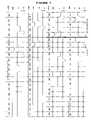
- FIGS. 3-8are plots of example valve timing during engine shutdown and/or cylinder deactivation
- Engine 10comprising a plurality of cylinders, one cylinder of which is shown in FIG. 1 , is controlled by electronic engine controller 12 .
- Engine 10includes combustion chamber 30 and cylinder walls 32 with piston 36 positioned therein and connected to crankshaft 40 .
- Combustion chamber 30is shown communicating with intake manifold 44 and exhaust manifold 48 via respective intake valve 52 an exhaust valve 54 .
- Each intake and exhaust valveis operated by an electromechanically controlled valve coil and armature assembly 53 , such as shown in FIG. 1A .
- Armature temperatureis determined by temperature sensor 51 .
- Valve positionis determined by position sensor 50 .
- each of valves actuators for valves 52 and 54has a position sensor and a temperature sensor.
- one or more of intake valve 52 and/or exhaust valve 54may be cam actuated, and be capable of mechanical deactivation.
- liftersmay include deactivation mechanism for push-rod type cam actuated valves.
- deactivators in an overhead cammay be used, such as by switching to a zero-lift cam profile.
- Intake manifold 44is also shown having fuel injector 66 coupled thereto for delivering liquid fuel in proportion to the pulse width of signal FPW from controller 12 .
- Fuelis delivered to fuel injector 66 by fuel system (not shown) including a fuel tank, fuel pump, and fuel rail (not shown).
- fuel systemincluding a fuel tank, fuel pump, and fuel rail (not shown).
- the enginemay be configured such that the fuel is injected directly into the engine cylinder, which is known to those skilled in the art as direct injection.
- intake manifold 44is shown communicating with optional electronic throttle 125 .
- Distributorless ignition system 88provides ignition spark to combustion chamber 30 via spark plug 92 in response to controller 12 .
- Universal Exhaust Gas Oxygen (UEGO) sensor 76is shown coupled to exhaust manifold 48 upstream of catalytic converter 70 .
- UEGOUniversal Exhaust Gas Oxygen
- Two-state exhaust gas oxygen sensor 98is shown coupled to exhaust manifold 48 downstream of catalytic converter 70 .
- sensor 98can also be a UEGO sensor.
- Catalytic converter temperatureis measured by temperature sensor 77 , and/or estimated based on operating conditions such as engine speed, load, air temperature, engine temperature, and/or airflow, or combinations thereof.
- Converter 70can include multiple catalyst bricks, in one example. In another example, multiple emission control devices, each with multiple bricks, can be used. Converter 70 can be a three-way type catalyst in one example.
- Controller 12is shown in FIG. 1 as a conventional microcomputer including: microprocessor unit 102 , input/output ports 104 , and read-only memory 106 , random access memory 108 , 110 keep alive memory, and a conventional data bus. Controller 12 is shown receiving various signals from sensors coupled to engine 10 , in addition to those signals previously discussed, including: engine coolant temperature (ECT) from temperature sensor 112 coupled to cooling sleeve 114 ; a position sensor 119 coupled to a accelerator pedal; a measurement of engine manifold pressure (MAP) from pressure sensor 122 coupled to intake manifold 44 ; a measurement (ACT) of engine air amount temperature or manifold temperature from temperature sensor 117 ; and a engine position sensor from a Hall effect sensor 118 sensing crankshaft 40 position.
- engine position sensor 118produces a predetermined number of equally spaced pulses every revolution of the crankshaft from which engine speed (RPM) can be determined.
- a direct injection type enginecan be used where injector 66 is positioned in combustion chamber 30 , either in the cylinder head similar to spark plug 92 , or on the side of the combustion chamber.
- the enginemay be coupled to an electric motor/battery system in a hybrid vehicle.
- the hybrid vehiclemay have a parallel configuration, series configuration, or variation or combinations thereof.
- FIG. 1Ashows an example dual coil oscillating mass actuator 240 with an engine valve actuated by a pair of opposing electromagnets (solenoids) 250 , 252 , which are designed to overcome the force of a pair of opposing valve springs 242 and 244 .
- FIG. 1Aalso shows port 310 , which can be an intake or exhaust port). Applying a variable voltage to the electromagnet's coil induces current to flow, which controls the force produced by each electromagnet. Due to the design illustrated, each electromagnet that makes up an actuator can only produce force in one direction, independent of the polarity of the current in its coil. High performance control and efficient generation of the required variable voltage can therefore be achieved by using a switch-mode power electronic converter. Alternatively, electromagnets with permanent magnets may be used that can be attracted or repelled.
- each valvegoes through an initialization cycle.
- the actuatorsare pulsed with current, in a prescribed manner, in order to establish the valves in the fully closed or fully open position.
- the valvesare sequentially actuated according to the desired valve timing (and firing order) by the pair of electromagnets, one for pulling the valve open (lower) and the other for pulling the valve closed (upper).
- each electromagnethas a magnetic property such that only a single electromagnet (upper or lower) need be energized at any time. Since the upper electromagnets hold the valves closed for the majority of each engine cycle, they are operated for a much higher percentage of time than that of the lower electromagnets.
- FIG. 1Aappears show the valves to be permanently attached to the actuators, in practice there can be a gap to accommodate lash and valve thermal expansion.
- routines described below in the flowchartsmay represent one or more of any number of processing strategies such as event-driven, interrupt-driven, multi-tasking, multi-threading, and the like. As such, various steps or functions illustrated may be performed in the sequence illustrated, in parallel, or in some cases omitted. Likewise, the order of processing is not necessarily required to achieve the features and advantages of the disclosure, but is provided for ease of illustration and description. Although not explicitly illustrated, one of ordinary skill in the art will recognize that one or more of the illustrated steps or functions may be repeatedly performed depending on the particular strategy being used. Further, these Figures graphically represent code to be programmed into the computer readable storage medium in controller 12 .
- the shut-downmay be a vehicle shut-down (such as key-off), an engine shut-down such as during a pure electric mode of a hybrid powertrain, or a partial engine shut-down (e.g., one or more cylinder deactivated).
- These featuresmay include adjusting valve opening/closing timing during the shut-down to draw a larger amount of a fuel puddle into the cylinder for combustion. They may also include adjusting valve opening/closing timing during the shut-down to increase engine braking to achieve a faster engine stopping time. Further, they may also include holding some valves (e.g., intake and/or exhaust) closed to reduce a flow of pumped gasses through the exhaust system during the shut-down. Further still, various combinations of these features may be used.
- step 210the routine determines if a request has been made to stop the engine or deactivate one or more cylinders.
- the requestmay be initiated by the driver of the vehicle or from within the vehicle control architecture, such as a hybrid-electric vehicle. If a request is present the routine proceeds to step 212 . If no request is present the routine proceeds to exit.
- step 212fuel is deactivated to individual cylinders based on the combustion order of the engine. That is, fuel injections that are in progress complete injection, and then fuel is deactivated. Then, in step 214 a determination is made as to whether fuel puddle reduction adjustments should be made. If so, in step 216 , calculations that determine the cylinder port fuel puddle mass continue and the intake valve duration are adjusted to produce the desired air-fuel ratio. Fuel puddle mass is determined with the method in accordance with U.S. Pat. No. 5,746,183 and is hereby fully incorporated by reference. In addition, spark may be adjusted in this step based on the request to stop the engine.
- sparkis adjusted to a value retarded from MBT (minimum advance for best torque) to reduce engine hydrocarbons and increase exhaust heat.
- MBTminimum advance for best torque
- catalyst temperaturemay be increased so that if the engine is restarted sometime soon, higher catalyst conversion efficiency may be achieved, due to a higher catalyst temperature.
- retarding spark during engine shut-downmay reduce evaporative emissions. Since hydrocarbon concentrations in exhaust gas may be reduced, exhaust gases that escape to the atmosphere during an engine stop may have fewer hydrocarbons.
- computer readable codecan be used to retard ignition timing on at least one of a group of final combustion events during the shut-down to increase exhaust temperature thereby improving emissions on a subsequent engine re-start.
- one or several combustion eventsare still carried out, e.g., 1, 2, 3, 4, or a range of combustion events depending on operating conditions, e.g., 1-5, 1-3, 1-2, etc.
- By adjusting the ignition timing of at least some of thesee.g., the last one, the last two, one of the last two or three
- adjusting of exhaust (or intake) valve opening and/or closing timing (or lift)can also be used (or alternatively used) to further increase exhaust gas heat to the catalyst during a shut-down.
- valve timingis adjusted.
- intake and exhaust valve timingmay be adjusted.
- the intake valve opening (IVO)can be moved, for example, to the engine position where a high intake port velocity is obtained, typically 45 degrees after the intake stroke begins. Moving the valve opening position to this location draws more fuel into the cylinder from the intake port puddle for a last combustion event. This can reduce the fuel puddle when the cylinder is deactivated or when the engine is stopped. Furthermore, a smaller fuel puddle contributes less fuel to a cylinder when the engine is restarted, thereby leading to more accurate air-fuel control during a start.
- the valvescan be operated with adjusted timing for at least an intake event, but may be operated longer if desired. Furthermore, the intake valve opening can be adjusted to a location of between 30 and 180 crank angle degrees after top-dead-center of the intake stroke.
- the intake valve closing timingcan also be adjusted to compensate air charge differences that may result from adjusting intake valve opening timing.
- the cylinder air-fuel mixture during engine shut-downmay be lean, rich, or stoichiometric depending on control objectives.
- exhaust valves and spark advancemay also be adjusted during engine shut-down.
- exhaust valvesare adjusted to an opening location of between 0 and 120 crank angle degrees after top-dead-center of the exhaust stroke.
- additional heatcan be added to the catalyst prior to engine shut-down. As mentioned above, this can increase catalyst temperature in anticipation of a subsequent start.
- the exhaust valve closing timingcan also be adjusted based on the adjusted exhaust valve opening time. The routine then proceeds to step 218 where fuel injection is then sequentially stopped for each cylinder after the final combustion event.
- valve opening/closing timing and durationcan be adjusted, and/or valves may be held closed.
- intake valvesmay be held open and exhaust valves held closed (of one or more, or all cylinders) to reduce flow through the exhaust.
- valve timing/durationmay be adjusted to generate expansion or compression braking.
- any one or more of the approaches described in U.S. Ser. No. 10/888,715, filed Jul. 8, 2004, attorney docket number 81099088, the entire contents of which is incorporated herein for all purposes,may be used.
- valve timingcan be adjusted where the exhaust valve is held closed and the intake valve is opened near TDC and closed near BDC and then opened again near TDC to generate compression braking.
- valve timingcan be adjusted where the exhaust valve is held closed and the intake valve is opened near BDC and closed near TDC and then opened again near BDC to generate expansion braking.
- the above exampledescribes some example situations where, prior to stopping an internal combustion engine, intake valve timing can be adjusted in a manner that improves starting the next time the engine is operated while at the same time stopping the engine faster. For example, opening the intake valves later in an intake stroke of a cylinder can reduce residual fuel left in an intake port after an engine is stopped. As a result, residual fuel from previous engine operation becomes a smaller fraction of the fuel entering the cylinder during a subsequent start. Consequently, the necessary amount of fuel injected to start the engine increases and the fuel injected becomes a greater fraction of the total amount of fuel entering a cylinder during a start. Because the mass of the fuel injected is known to a greater certainty than an estimate of residual fuel, a more consistent and higher accuracy air-fuel ratio may result during a start.
- the methodcan improve engine air-fuel ratio control and reduce emissions during a start since less residual fuel is present in the intake manifold when the engine is restarted. This can be especially advantageous when a catalyst is cold and its efficiency is low. In addition, less fuel is available to evaporate from the intake manifold, which can reduce evaporative emissions.
- FIGS. 3-8various examples of operation are described.
- the sequences shown in FIGS. 3-8are not actual engine data but are shown for illustration purposes and the actual number of events during an engine shut-down may be more or less than those illustrated.
- FIG. 3shows example intake and exhaust valve events, injection timing, and spark events for a four cylinder engine with adjustable intake and exhaust valve timing after a request to stop the engine is made.
- Each of the four piston positionsis shown by angular degrees referenced to top-dead-center of the respective cylinder (i.e., 0 is top-dead-center of compression).
- a request to stop the engineis illustrated by the vertical line that divides engine events into two sections; pre-request and post-request.
- intake valvesare adjusted (denoted IVO shift) to a retarded position in an effort to reduce fuel that may be puddled in the intake manifold and/or cylinder head.
- the intake valvesare opened near the top and bottom of subsequent piston strokes.
- compression and expansion workcan be used to increase engine deceleration since little energy is recovered after expansion or compression.
- the illustrated sequencecan reduce engine emissions because the amount of oxygen pumped to a catalyst during a stop is reduced. Also, the amount of exhaust gas trapped in a cylinder is reduced, which may improve engine restarts. Furthermore, the engine can stop quicker leading to fewer combustion events during a stop (i.e., fewer combustion events may lead to reduced fuel consumption and emissions). Moreover, by controlling expansion and compression work, the engine stop location may be better controlled.
- the number on intake compression/expansion relief valve events and the number of combustion events after IVO shiftmay be constant or may vary by engine operating conditions.
- the exhaust valvesmay be held in a closed position after a final intake stoke in a respective cylinder.
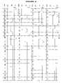
- FIG. 4the sequence shown is similar to the sequence of FIG. 3 , but the intake valves are held closed until the engine speed is substantially zero. By holding the intake valves closed, some compression and/or expansion work may be recovered so that the engine coastdown (i.e., time to reach zero speed from a request to stop) is increased.
- the benefits of the example of FIG. 4are similar to those of the sequence of FIG. 3 .
- the exhaust valvesmay be held in a closed position (while intake valves operate or not) after a final intake stoke in a respective cylinder.
- intake valvesmay be held closed while exhaust valves continue to operate after a final combustion event in the respective cylinder.
- FIG. 5a sequence shown that is similar to the sequence of FIG. 4 , but the exhaust valves are opened and closed until engine speed is substantially zero to increase engine expansion and compression work.
- opening and closing the exhaust valves near top-dead-center and bottom-dead-centercan reduce energy recovery of compression and expansion.
- the benefits of the FIG. 5 sequenceare similar to those of the sequence of FIG. 3 .
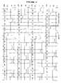
- FIG. 6it shows a valve sequence that can reduce engine pumping work and catalyst oxidation during an engine shut-down.
- fuel and sparkare customarily deactivated so that the individual cylinders do not continue to combust air-fuel mixtures. Even though spark and fuel have been deactivated, engine inertia can cause the engine to continue to rotate. If valve timing continues in the same manner as prior to the request to stop the engine (e.g., four stroke cycle), air may be pumped through the engine to a catalyst.
- An oxygenated catalysti.e., a catalyst with excess oxygen stored throughout or within a portion of a catalyst
- An oxygenated catalystmay increase fuel consumption during a restart since additional fuel may be necessary to reset the state of the catalyst such that both oxidation and reduction may occur within the catalyst.
- intake and exhaust valvesmay be reduced along with emissions and fuel consumption.
- intake and/or exhaust valvesmay be kept closed on a hybrid vehicle where an IC engine may be started and stopped a number of times during a normal drive. By keeping intake and/or exhaust valves closed during a soak period, oxidation caused by convective exhaust cooling, can be further decreased.
- valve timing for a four-cylinder engine with valves that may be selectively activated during an engine shutdownis shown.
- IVOis shifted and a last combustion event occurs in each cylinder.
- the exhaust valvesare opened and remain open until engine speed is substantially zero, at which time the intake and exhaust valves are released to a neutral position.
- the intake valvesremain closed after the final intake event until the engine speed is substantially zero. Allowing the exhaust valve to remain open during coast-down, while intake valves are closed, can reduce engine pumping work.
- the energy recovered by reducing engine pumping workmay be captured by an electric motor or used to further propel a hybrid vehicle.
- intake valvescan be held open while exhaust valves are closed after the final combustion cycle is completed (i.e., after the exhaust valves close).
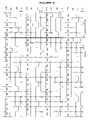
- FIG. 7an alternate method to control intake and exhaust valves during an engine shut-down is shown.
- This methodcontinues to operate both intake and exhaust valves after a request to stop the engine is made until engine speed is substantially zero, when the valves are released to a neutral position.
- the intake valvesare held open during a predetermined interval so that air flow through the engine is reduced. Namely, the intake valves are opened after the exhaust valves close (between ⁇ 30 to +30 degrees after TDC exhaust stroke) and closed before the exhaust valves open (between ⁇ 30 to +30 degrees after TDC compression stroke).
- the exhaust valveopens prior to the exhaust stroke and remains open until the end of the exhaust stroke.
- valve timingdifferent from those illustrated, may be used without deviating from the intent to reduce pumping work and air flow through the engine.
- a partial number of cylindersmay complete a fueled intake stroke after the request to stop the engine is made so that the shut-down sequence begins sooner.
- FIG. 8another alternate method to control intake and exhaust valves during an engine shut-down is shown.
- This methodcontinues to operate both intake and exhaust valves after a request to stop the engine is made until engine speed is substantially zero, when the valves are released to a neutral position.
- the intake valvesare held closed except near ( ⁇ 30 degrees) BDC intake and TDC compression strokes where they are opened to release expansion or compression work.
- the exhaust valveopens prior to the exhaust stroke and remains open until the end of the exhaust stroke.
- small variations in valve timingdifferent from those illustrated, may be used without deviating from the intent to increase pumping work and decrease air flow through the engine.
- the opening/closing timesmay be adjusted to vary the amount of braking torque generated.
- the sequencemay be used to quickly stop engine rotation while reducing air flow through the engine. This may be beneficial to reduce engine emissions and to reduce perceived engine run-on.
- a final combustion event in each cylinder of the engineis not necessary for any of the above sequences.
- Some cylindersmay initiate a valve timing change immediately following the request to stop the engine.
- FIGS. 7-8may be especially advantages for systems with electrically actuated intake valves and mechanically cam actuated exhaust valves, for example.
- one or more intake and/or exhaust valvescan be held closed for one or more cycles during engine starting and/or cranking.
- exhaust valvesmay be held closed until a fist combustion event in the cylinder.
Landscapes
- Engineering & Computer Science (AREA)
- Mechanical Engineering (AREA)
- General Engineering & Computer Science (AREA)
- Chemical & Material Sciences (AREA)
- Combustion & Propulsion (AREA)
- Physics & Mathematics (AREA)
- Electromagnetism (AREA)
- Output Control And Ontrol Of Special Type Engine (AREA)
- Combined Controls Of Internal Combustion Engines (AREA)
- Valve Device For Special Equipments (AREA)
- Electrical Control Of Air Or Fuel Supplied To Internal-Combustion Engine (AREA)
- Electrical Control Of Ignition Timing (AREA)
Abstract
Description
The present application is a divisional of U.S. patent application Ser. No. 11/079,968, filed on Mar. 14, 2005, now U.S. Pat. No. 7,047,126 which is a continuation-in-part of U.S. patent application Ser. No. 10/805,648, filed Mar. 19, 2004, now U.S. Pat. No. 7,021,289 the entire contents of each are incorporated herein by reference in their entirety for all purposes.
The present description relates to a method for improving a shut-down of an internal combustion engine and more particularly to a method for controlling electromechanical intake and/or exhaust valves to improve shut-down and re-starting of an internal combustion engine.
The inventors herein have recognized that the number of cycles completed by an engine during an engine shutdown can affect emissions on subsequent engine starts. Specifically, after fuel injection is stopped, the engine may continue to rotate, thus pumping lean gasses to the catalyst thereby increasing its oxidation state. Then, during subsequent restarts, the oxidized catalyst may perform less efficiently.
In one example, this can be addressed by a method for operating at least an intake and exhaust valve in a cylinder with a piston of an engine in a vehicle, comprising:
during conditions of an engine shut-down, maintaining at least one of the intake and exhaust valves in a closed position during a period, and during at least said period where said at least one valve is in said closed position: operating with the other of the intake and exhaust valve open, then closing the other of the intake and exhaust valve, and then opening the other of the intake and exhaust valve to generate braking torque to slow the engine.
It this way, it may be possible to reduce stopping engine stopping time and thereby pump fewer gasses through the catalyst. Further, other advantages may be obtained as discussed in detail below.
Referring toFIG. 1 ,internal combustion engine 10, comprising a plurality of cylinders, one cylinder of which is shown inFIG. 1 , is controlled byelectronic engine controller 12.Engine 10 includescombustion chamber 30 andcylinder walls 32 withpiston 36 positioned therein and connected tocrankshaft 40.Combustion chamber 30 is shown communicating withintake manifold 44 andexhaust manifold 48 viarespective intake valve 52 anexhaust valve 54. Each intake and exhaust valve is operated by an electromechanically controlled valve coil andarmature assembly 53, such as shown inFIG. 1A . Armature temperature is determined bytemperature sensor 51. Valve position is determined byposition sensor 50. In an alternative example, each of valves actuators forvalves intake valve 52 and/orexhaust valve 54 may be cam actuated, and be capable of mechanical deactivation. For example, lifters may include deactivation mechanism for push-rod type cam actuated valves. Alternatively, deactivators in an overhead cam may be used, such as by switching to a zero-lift cam profile.
Converter70 can include multiple catalyst bricks, in one example. In another example, multiple emission control devices, each with multiple bricks, can be used. Converter70 can be a three-way type catalyst in one example.
In an alternative embodiment, a direct injection type engine can be used whereinjector 66 is positioned incombustion chamber 30, either in the cylinder head similar tospark plug 92, or on the side of the combustion chamber. Also, the engine may be coupled to an electric motor/battery system in a hybrid vehicle. The hybrid vehicle may have a parallel configuration, series configuration, or variation or combinations thereof.
As illustrated above, the electromechanically actuated valves in the engine remain in the half open position when the actuators are de-energized. Therefore, prior to engine combustion operation, each valve goes through an initialization cycle. During the initialization period, the actuators are pulsed with current, in a prescribed manner, in order to establish the valves in the fully closed or fully open position. Following this initialization, the valves are sequentially actuated according to the desired valve timing (and firing order) by the pair of electromagnets, one for pulling the valve open (lower) and the other for pulling the valve closed (upper).
The magnetic properties of each electromagnet are such that only a single electromagnet (upper or lower) need be energized at any time. Since the upper electromagnets hold the valves closed for the majority of each engine cycle, they are operated for a much higher percentage of time than that of the lower electromagnets.
WhileFIG. 1A appears show the valves to be permanently attached to the actuators, in practice there can be a gap to accommodate lash and valve thermal expansion.
As will be appreciated by one of ordinary skill in the art, the specific routines described below in the flowcharts may represent one or more of any number of processing strategies such as event-driven, interrupt-driven, multi-tasking, multi-threading, and the like. As such, various steps or functions illustrated may be performed in the sequence illustrated, in parallel, or in some cases omitted. Likewise, the order of processing is not necessarily required to achieve the features and advantages of the disclosure, but is provided for ease of illustration and description. Although not explicitly illustrated, one of ordinary skill in the art will recognize that one or more of the illustrated steps or functions may be repeatedly performed depending on the particular strategy being used. Further, these Figures graphically represent code to be programmed into the computer readable storage medium incontroller 12.
Referring now toFIG. 2 , a routine is described for controlling an engine shut down. Various features may be used during the engine shut-down. The shut-down may be a vehicle shut-down (such as key-off), an engine shut-down such as during a pure electric mode of a hybrid powertrain, or a partial engine shut-down (e.g., one or more cylinder deactivated). These features may include adjusting valve opening/closing timing during the shut-down to draw a larger amount of a fuel puddle into the cylinder for combustion. They may also include adjusting valve opening/closing timing during the shut-down to increase engine braking to achieve a faster engine stopping time. Further, they may also include holding some valves (e.g., intake and/or exhaust) closed to reduce a flow of pumped gasses through the exhaust system during the shut-down. Further still, various combinations of these features may be used.
Referring now specifically toFIG. 2 , instep 210 the routine determines if a request has been made to stop the engine or deactivate one or more cylinders. The request may be initiated by the driver of the vehicle or from within the vehicle control architecture, such as a hybrid-electric vehicle. If a request is present the routine proceeds to step212. If no request is present the routine proceeds to exit.
Instep 212, fuel is deactivated to individual cylinders based on the combustion order of the engine. That is, fuel injections that are in progress complete injection, and then fuel is deactivated. Then, in step214 a determination is made as to whether fuel puddle reduction adjustments should be made. If so, instep 216, calculations that determine the cylinder port fuel puddle mass continue and the intake valve duration are adjusted to produce the desired air-fuel ratio. Fuel puddle mass is determined with the method in accordance with U.S. Pat. No. 5,746,183 and is hereby fully incorporated by reference. In addition, spark may be adjusted in this step based on the request to stop the engine. In one example, spark is adjusted to a value retarded from MBT (minimum advance for best torque) to reduce engine hydrocarbons and increase exhaust heat. For example, adjusting spark during shut-down, catalyst temperature may be increased so that if the engine is restarted sometime soon, higher catalyst conversion efficiency may be achieved, due to a higher catalyst temperature. In another example, retarding spark during engine shut-down may reduce evaporative emissions. Since hydrocarbon concentrations in exhaust gas may be reduced, exhaust gases that escape to the atmosphere during an engine stop may have fewer hydrocarbons.
Thus, in some examples, during an engine shut-down operation, computer readable code can be used to retard ignition timing on at least one of a group of final combustion events during the shut-down to increase exhaust temperature thereby improving emissions on a subsequent engine re-start. In one example, upon receiving a command to shut-down the engine, one or several combustion events are still carried out, e.g., 1, 2, 3, 4, or a range of combustion events depending on operating conditions, e.g., 1-5, 1-3, 1-2, etc. By adjusting the ignition timing of at least some of these (e.g., the last one, the last two, one of the last two or three), it is possible to improve later re-starts that are performed before the catalyst has cooled. Further, as noted above, adjusting of exhaust (or intake) valve opening and/or closing timing (or lift) can also be used (or alternatively used) to further increase exhaust gas heat to the catalyst during a shut-down.
Instep 216, valve timing is adjusted. Thus, upon indication of a request to stop or cylinder deactivation, intake and exhaust valve timing may be adjusted. The intake valve opening (IVO) can be moved, for example, to the engine position where a high intake port velocity is obtained, typically 45 degrees after the intake stroke begins. Moving the valve opening position to this location draws more fuel into the cylinder from the intake port puddle for a last combustion event. This can reduce the fuel puddle when the cylinder is deactivated or when the engine is stopped. Furthermore, a smaller fuel puddle contributes less fuel to a cylinder when the engine is restarted, thereby leading to more accurate air-fuel control during a start.
The valves can be operated with adjusted timing for at least an intake event, but may be operated longer if desired. Furthermore, the intake valve opening can be adjusted to a location of between 30 and 180 crank angle degrees after top-dead-center of the intake stroke. The intake valve closing timing can also be adjusted to compensate air charge differences that may result from adjusting intake valve opening timing.
The cylinder air-fuel mixture during engine shut-down may be lean, rich, or stoichiometric depending on control objectives.
In addition, the exhaust valves and spark advance may also be adjusted during engine shut-down. For example, exhaust valves are adjusted to an opening location of between 0 and 120 crank angle degrees after top-dead-center of the exhaust stroke. When this exhaust valve timing is combined with a spark angle adjustment, additional heat can be added to the catalyst prior to engine shut-down. As mentioned above, this can increase catalyst temperature in anticipation of a subsequent start. Further the exhaust valve closing timing can also be adjusted based on the adjusted exhaust valve opening time. The routine then proceeds to step218 where fuel injection is then sequentially stopped for each cylinder after the final combustion event.
Then, the routine proceeds to step220 and determines whether flow reduction and/or increased engine braking is requested. If not, the routine ends. If so, the routine proceeds to step222 where valve opening/closing timing and duration can be adjusted, and/or valves may be held closed. For example, intake valves may be held open and exhaust valves held closed (of one or more, or all cylinders) to reduce flow through the exhaust. In another example, valve timing/duration may be adjusted to generate expansion or compression braking. For example, any one or more of the approaches described in U.S. Ser. No. 10/888,715, filed Jul. 8, 2004, attorney docket number 81099088, the entire contents of which is incorporated herein for all purposes, may be used. Examples of such operation are described in more detail in the examples below. For example, valve timing can be adjusted where the exhaust valve is held closed and the intake valve is opened near TDC and closed near BDC and then opened again near TDC to generate compression braking. In another example, valve timing can be adjusted where the exhaust valve is held closed and the intake valve is opened near BDC and closed near TDC and then opened again near BDC to generate expansion braking.
Thus, the above example describes some example situations where, prior to stopping an internal combustion engine, intake valve timing can be adjusted in a manner that improves starting the next time the engine is operated while at the same time stopping the engine faster. For example, opening the intake valves later in an intake stroke of a cylinder can reduce residual fuel left in an intake port after an engine is stopped. As a result, residual fuel from previous engine operation becomes a smaller fraction of the fuel entering the cylinder during a subsequent start. Consequently, the necessary amount of fuel injected to start the engine increases and the fuel injected becomes a greater fraction of the total amount of fuel entering a cylinder during a start. Because the mass of the fuel injected is known to a greater certainty than an estimate of residual fuel, a more consistent and higher accuracy air-fuel ratio may result during a start.
The present disclosure may provide several advantages. For example, the method can improve engine air-fuel ratio control and reduce emissions during a start since less residual fuel is present in the intake manifold when the engine is restarted. This can be especially advantageous when a catalyst is cold and its efficiency is low. In addition, less fuel is available to evaporate from the intake manifold, which can reduce evaporative emissions.
Referring now toFIGS. 3-8 , various examples of operation are described. The sequences shown inFIGS. 3-8 are not actual engine data but are shown for illustration purposes and the actual number of events during an engine shut-down may be more or less than those illustrated.
Alternatively, the exhaust valves may be held in a closed position after a final intake stoke in a respective cylinder.
Referring now toFIG. 4 , the sequence shown is similar to the sequence ofFIG. 3 , but the intake valves are held closed until the engine speed is substantially zero. By holding the intake valves closed, some compression and/or expansion work may be recovered so that the engine coastdown (i.e., time to reach zero speed from a request to stop) is increased. The benefits of the example ofFIG. 4 are similar to those of the sequence ofFIG. 3 .
Alternatively, the exhaust valves may be held in a closed position (while intake valves operate or not) after a final intake stoke in a respective cylinder.
In yet another alternative, intake valves may be held closed while exhaust valves continue to operate after a final combustion event in the respective cylinder.
Referring now toFIG. 5 , a sequence shown that is similar to the sequence ofFIG. 4 , but the exhaust valves are opened and closed until engine speed is substantially zero to increase engine expansion and compression work. As mentioned in the description ofFIG. 5 , opening and closing the exhaust valves near top-dead-center and bottom-dead-center can reduce energy recovery of compression and expansion. The benefits of theFIG. 5 sequence are similar to those of the sequence ofFIG. 3 .
Referring now toFIG. 6 , it shows a valve sequence that can reduce engine pumping work and catalyst oxidation during an engine shut-down. After an operator request to stop an engine, fuel and spark are customarily deactivated so that the individual cylinders do not continue to combust air-fuel mixtures. Even though spark and fuel have been deactivated, engine inertia can cause the engine to continue to rotate. If valve timing continues in the same manner as prior to the request to stop the engine (e.g., four stroke cycle), air may be pumped through the engine to a catalyst. An oxygenated catalyst (i.e., a catalyst with excess oxygen stored throughout or within a portion of a catalyst) may increase fuel consumption during a restart since additional fuel may be necessary to reset the state of the catalyst such that both oxidation and reduction may occur within the catalyst. By selectively operating intake and exhaust valves during shut-down and start-up catalyst oxidation may be reduced along with emissions and fuel consumption. Furthermore, intake and/or exhaust valves may be kept closed on a hybrid vehicle where an IC engine may be started and stopped a number of times during a normal drive. By keeping intake and/or exhaust valves closed during a soak period, oxidation caused by convective exhaust cooling, can be further decreased.
Continuing withFIG. 6 , valve timing for a four-cylinder engine with valves that may be selectively activated during an engine shutdown is shown. After a request to stop the engine is made, IVO is shifted and a last combustion event occurs in each cylinder. As mentioned above, it is not necessary to have a final intake and combustion event for each cylinder if fuel puddling is of little or no concern. After a final combustion event in each of the respective cylinders, the exhaust valves are opened and remain open until engine speed is substantially zero, at which time the intake and exhaust valves are released to a neutral position. The intake valves remain closed after the final intake event until the engine speed is substantially zero. Allowing the exhaust valve to remain open during coast-down, while intake valves are closed, can reduce engine pumping work. The energy recovered by reducing engine pumping work may be captured by an electric motor or used to further propel a hybrid vehicle. By leaving intake valves closed and exhaust valves open, oxygen pumped through the engine during shut-down is reduced without increasing engine pumping work.
Alternatively, intake valves can be held open while exhaust valves are closed after the final combustion cycle is completed (i.e., after the exhaust valves close).
Referring now toFIG. 7 , an alternate method to control intake and exhaust valves during an engine shut-down is shown. This method continues to operate both intake and exhaust valves after a request to stop the engine is made until engine speed is substantially zero, when the valves are released to a neutral position. After a final combustion cycle is completed in each respective cylinder, the intake valves are held open during a predetermined interval so that air flow through the engine is reduced. Namely, the intake valves are opened after the exhaust valves close (between −30 to +30 degrees after TDC exhaust stroke) and closed before the exhaust valves open (between −30 to +30 degrees after TDC compression stroke). The exhaust valve opens prior to the exhaust stroke and remains open until the end of the exhaust stroke. Of course, small variations in valve timing, different from those illustrated, may be used without deviating from the intent to reduce pumping work and air flow through the engine.
Alternatively, a partial number of cylinders may complete a fueled intake stroke after the request to stop the engine is made so that the shut-down sequence begins sooner.
Referring now toFIG. 8 , another alternate method to control intake and exhaust valves during an engine shut-down is shown. This method continues to operate both intake and exhaust valves after a request to stop the engine is made until engine speed is substantially zero, when the valves are released to a neutral position. After a final combustion cycle is completed in each respective cylinder, the intake valves are held closed except near (±30 degrees) BDC intake and TDC compression strokes where they are opened to release expansion or compression work. The exhaust valve opens prior to the exhaust stroke and remains open until the end of the exhaust stroke. Of course, small variations in valve timing, different from those illustrated, may be used without deviating from the intent to increase pumping work and decrease air flow through the engine. Further, the opening/closing times may be adjusted to vary the amount of braking torque generated. The sequence may be used to quickly stop engine rotation while reducing air flow through the engine. This may be beneficial to reduce engine emissions and to reduce perceived engine run-on.
A final combustion event in each cylinder of the engine is not necessary for any of the above sequences. Some cylinders may initiate a valve timing change immediately following the request to stop the engine.
The approach ofFIGS. 7-8 may be especially advantages for systems with electrically actuated intake valves and mechanically cam actuated exhaust valves, for example.
Note that the above approaches can be combined with engine starting approaches that further reduce flow through the exhaust system. For example, one or more intake and/or exhaust valves can be held closed for one or more cycles during engine starting and/or cranking. For example, exhaust valves may be held closed until a fist combustion event in the cylinder.
It will be appreciated that the configurations and routines disclosed herein are exemplary in nature, and that these specific embodiments are not to be considered in a limiting sense, because numerous variations are possible. For example, the above approaches can be applied to V-6, I-4, I-6, V-12, opposed 4, and other engine types. Also, the approaches described above are not specifically limited to a dual coil valve actuator. Rather, it could be applied to other forms of actuators, including ones that have only a single coil per valve actuator, and/or other variable valve timing systems, such as, for example, cam phasing, cam profile switching, variable rocker ratio, etc.
The subject matter of the present disclosure includes all novel and nonobvious combinations and subcombinations of the various systems and configurations, and other features, functions, and/or properties disclosed herein.
The following claims particularly point out certain combinations and subcombinations regarded as novel and nonobvious. These claims may refer to “an” element or “a first” element or the equivalent thereof. Such claims should be understood to include incorporation of one or more such elements, neither requiring nor excluding two or more such elements. Other combinations and subcombinations of the disclosed features, functions, elements, and/or properties may be claimed through amendment of the present claims or through presentation of new claims in this or a related application. Such claims, whether broader, narrower, equal, or different in scope to the original claims, also are regarded as included within the subject matter of the present disclosure.
Claims (8)
1. A method for operating at least an intake and exhaust valve in a cylinder with a piston of an engine in a vehicle, comprising:
during conditions of an engine shut-down, maintaining at least one of the intake and exhaust valves in a closed position, and during conditions where said at least one valve is in said closed position:
operating with the other of the intake and exhaust valve open, then closing the other of the intake and exhaust valve, and then opening the other of the intake and exhaust valve to generate braking torque to slow the engine.
2. The method ofclaim 1 wherein the other of the intake and exhaust valve is an electrically actuated valve.
3. The method ofclaim 2 wherein said at least one of the intake and exhaust valves is an electrically actuated valve.
4. The method ofclaim 1 wherein during said conditions, the other of the intake and exhaust valve is operated without performing combustion in the cylinder.
5. A computer storage medium having instructions encoded therein for operating at least an intake and exhaust valve in a cylinder with a piston of an engine in a vehicle, said medium comprising:
code for, during at least two sequential strokes of the piston during an engine shut-down:
maintaining at least one of the intake and exhaust valves closed while opening the other of the intake and exhaust valves twice to slow said engine.
6. The medium ofclaim 5 wherein the other of the intake and exhaust valve is an electrically actuated valve.
7. The medium ofclaim 6 wherein said at least one of the intake and exhaust valves is an electrically actuated valve.
8. The medium ofclaim 5 wherein during said at least two sequential strokes the other of the intake and exhaust valve is operated twice without performing combustion in the cylinder.
Priority Applications (2)
| Application Number | Priority Date | Filing Date | Title |
|---|---|---|---|
| US11/379,755US7317984B2 (en) | 2004-03-19 | 2006-04-21 | Engine shut-down for engine having adjustable valve timing |
| US11/968,313US7549406B2 (en) | 2004-03-19 | 2008-01-02 | Engine shut-down for engine having adjustable valve timing |
Applications Claiming Priority (3)
| Application Number | Priority Date | Filing Date | Title |
|---|---|---|---|
| US10/805,648US7021289B2 (en) | 2004-03-19 | 2004-03-19 | Reducing engine emissions on an engine with electromechanical valves |
| US11/079,968US7047126B2 (en) | 2004-03-19 | 2005-03-14 | Engine shut-down for engine having adjustable valve timing |
| US11/379,755US7317984B2 (en) | 2004-03-19 | 2006-04-21 | Engine shut-down for engine having adjustable valve timing |
Related Parent Applications (1)
| Application Number | Title | Priority Date | Filing Date |
|---|---|---|---|
| US11/079,968DivisionUS7047126B2 (en) | 2004-03-19 | 2005-03-14 | Engine shut-down for engine having adjustable valve timing |
Related Child Applications (1)
| Application Number | Title | Priority Date | Filing Date |
|---|---|---|---|
| US11/968,313DivisionUS7549406B2 (en) | 2004-03-19 | 2008-01-02 | Engine shut-down for engine having adjustable valve timing |
Publications (2)
| Publication Number | Publication Date |
|---|---|
| US20060201458A1 US20060201458A1 (en) | 2006-09-14 |
| US7317984B2true US7317984B2 (en) | 2008-01-08 |
Family
ID=34838963
Family Applications (6)
| Application Number | Title | Priority Date | Filing Date |
|---|---|---|---|
| US10/805,648Expired - LifetimeUS7021289B2 (en) | 2004-03-19 | 2004-03-19 | Reducing engine emissions on an engine with electromechanical valves |
| US11/080,060Expired - LifetimeUS7011075B2 (en) | 2004-03-19 | 2005-03-14 | Engine shut-down for engine having adjustable valve timing |
| US11/079,968Expired - LifetimeUS7047126B2 (en) | 2004-03-19 | 2005-03-14 | Engine shut-down for engine having adjustable valve timing |
| US11/339,175Expired - LifetimeUS7165520B2 (en) | 2004-03-19 | 2006-01-23 | Reducing engine emission on an engine with electromechanical valves |
| US11/379,755Expired - LifetimeUS7317984B2 (en) | 2004-03-19 | 2006-04-21 | Engine shut-down for engine having adjustable valve timing |
| US11/968,313Expired - Fee RelatedUS7549406B2 (en) | 2004-03-19 | 2008-01-02 | Engine shut-down for engine having adjustable valve timing |
Family Applications Before (4)
| Application Number | Title | Priority Date | Filing Date |
|---|---|---|---|
| US10/805,648Expired - LifetimeUS7021289B2 (en) | 2004-03-19 | 2004-03-19 | Reducing engine emissions on an engine with electromechanical valves |
| US11/080,060Expired - LifetimeUS7011075B2 (en) | 2004-03-19 | 2005-03-14 | Engine shut-down for engine having adjustable valve timing |
| US11/079,968Expired - LifetimeUS7047126B2 (en) | 2004-03-19 | 2005-03-14 | Engine shut-down for engine having adjustable valve timing |
| US11/339,175Expired - LifetimeUS7165520B2 (en) | 2004-03-19 | 2006-01-23 | Reducing engine emission on an engine with electromechanical valves |
Family Applications After (1)
| Application Number | Title | Priority Date | Filing Date |
|---|---|---|---|
| US11/968,313Expired - Fee RelatedUS7549406B2 (en) | 2004-03-19 | 2008-01-02 | Engine shut-down for engine having adjustable valve timing |
Country Status (4)
| Country | Link |
|---|---|
| US (6) | US7021289B2 (en) |
| EP (1) | EP1577523B1 (en) |
| JP (1) | JP2005264947A (en) |
| CN (1) | CN100520015C (en) |
Cited By (8)
| Publication number | Priority date | Publication date | Assignee | Title |
|---|---|---|---|---|
| US20070125350A1 (en)* | 2005-12-05 | 2007-06-07 | Toyota Jidosha Kabushiki Kaisha | Air-fuel ratio control apparatus |
| US20070273153A1 (en)* | 2006-05-08 | 2007-11-29 | Towertech Research Group | Combustion engine driven electric generator apparatus |
| US20080098980A1 (en)* | 2004-03-19 | 2008-05-01 | Ford Global Technologies, Llc | Engine shut-down for engine having adjustable valve timing |
| US7438042B1 (en)* | 2007-05-17 | 2008-10-21 | Mazda Motor Corporation | Method of stopping internal combustion engine |
| US20110088644A1 (en)* | 2009-10-16 | 2011-04-21 | Hitachi Automotive Systems, Ltd. | Internal Combustion Engine Control Device and Internal Combustion Engine Control System |
| US20110226203A1 (en)* | 2010-03-22 | 2011-09-22 | Gm Global Technology Operations, Inc. | Engine including system and method for reducing oil pull-over in combustion chamber |
| US20110288753A1 (en)* | 2008-12-09 | 2011-11-24 | Honda Motor Co., Ltd. | Device and method for controlling timing at which ignition is stopped when internal combustion engine becomes stopped |
| US20130013136A1 (en)* | 2011-07-06 | 2013-01-10 | GM Global Technology Operations LLC | System and method for increasing operating efficiency of a hybrid vehicle |
Families Citing this family (67)
| Publication number | Priority date | Publication date | Assignee | Title |
|---|---|---|---|---|
| US7079935B2 (en) | 2004-03-19 | 2006-07-18 | Ford Global Technologies, Llc | Valve control for an engine with electromechanically actuated valves |
| US7383820B2 (en)* | 2004-03-19 | 2008-06-10 | Ford Global Technologies, Llc | Electromechanical valve timing during a start |
| US7128043B2 (en)* | 2004-03-19 | 2006-10-31 | Ford Global Technologies, Llc | Electromechanically actuated valve control based on a vehicle electrical system |
| US7555896B2 (en)* | 2004-03-19 | 2009-07-07 | Ford Global Technologies, Llc | Cylinder deactivation for an internal combustion engine |
| US7063062B2 (en) | 2004-03-19 | 2006-06-20 | Ford Global Technologies, Llc | Valve selection for an engine operating in a multi-stroke cylinder mode |
| US7107947B2 (en)* | 2004-03-19 | 2006-09-19 | Ford Global Technologies, Llc | Multi-stroke cylinder operation in an internal combustion engine |
| US7165391B2 (en)* | 2004-03-19 | 2007-01-23 | Ford Global Technologies, Llc | Method to reduce engine emissions for an engine capable of multi-stroke operation and having a catalyst |
| US7107946B2 (en)* | 2004-03-19 | 2006-09-19 | Ford Global Technologies, Llc | Electromechanically actuated valve control for an internal combustion engine |
| US7194993B2 (en) | 2004-03-19 | 2007-03-27 | Ford Global Technologies, Llc | Starting an engine with valves that may be deactivated |
| US7559309B2 (en)* | 2004-03-19 | 2009-07-14 | Ford Global Technologies, Llc | Method to start electromechanical valves on an internal combustion engine |
| US7240663B2 (en) | 2004-03-19 | 2007-07-10 | Ford Global Technologies, Llc | Internal combustion engine shut-down for engine having adjustable valves |
| US7072758B2 (en) | 2004-03-19 | 2006-07-04 | Ford Global Technologies, Llc | Method of torque control for an engine with valves that may be deactivated |
| US7032581B2 (en) | 2004-03-19 | 2006-04-25 | Ford Global Technologies, Llc | Engine air-fuel control for an engine with valves that may be deactivated |
| US7140355B2 (en) | 2004-03-19 | 2006-11-28 | Ford Global Technologies, Llc | Valve control to reduce modal frequencies that may cause vibration |
| US7066121B2 (en) | 2004-03-19 | 2006-06-27 | Ford Global Technologies, Llc | Cylinder and valve mode control for an engine with valves that may be deactivated |
| US7128687B2 (en)* | 2004-03-19 | 2006-10-31 | Ford Global Technologies, Llc | Electromechanically actuated valve control for an internal combustion engine |
| US7136742B2 (en)* | 2004-09-30 | 2006-11-14 | Walbro Engine Management, L.L.C. | Engine kill-switch control circuit and method of operating the same |
| DE102005001047B4 (en)* | 2005-01-07 | 2018-08-16 | Volkswagen Ag | Method for operating a hybrid vehicle and hybrid vehicle |
| DE102005001046B4 (en)* | 2005-01-07 | 2014-11-06 | Volkswagen Ag | A method of operating a hybrid vehicle and hybrid vehicle having a multi-cylinder internal combustion engine coupled to an electric machine |
| US8763582B2 (en)* | 2005-05-12 | 2014-07-01 | Ford Global Technologies, Llc | Engine starting for engine having adjustable valve operation and port fuel injection |
| US7469667B2 (en) | 2005-07-07 | 2008-12-30 | Ford Global Technologies, Llc | Method for controlling a variable event valvetrain |
| US7296550B2 (en) | 2005-09-12 | 2007-11-20 | Ford Global Technologies, Llc | Starting an engine having a variable event valvetrain |
| US7461619B2 (en) | 2005-09-23 | 2008-12-09 | Jp Scope Llc | Valve apparatus for an internal combustion engine |
| US8528511B2 (en) | 2005-09-23 | 2013-09-10 | Jp Scope, Inc. | Variable travel valve apparatus for an internal combustion engine |
| JP2007100660A (en)* | 2005-10-07 | 2007-04-19 | Hitachi Ltd | Vehicle engine start preparation device |
| US7167792B1 (en) | 2006-01-23 | 2007-01-23 | Ford Global Technologies, Llc | Method for stopping and starting an internal combustion engine having a variable event valvetrain |
| JP2007247476A (en)* | 2006-03-14 | 2007-09-27 | Honda Motor Co Ltd | Control device for internal combustion engine |
| US7621126B2 (en)* | 2006-04-05 | 2009-11-24 | Ford Global Technoloigies, LLC | Method for controlling cylinder air charge for a turbo charged engine having variable event valve actuators |
| US7562530B2 (en)* | 2006-04-05 | 2009-07-21 | Ford Global Technologies, Llc | Method for controlling an internal combustion engine having a variable event valvetrain |
| US7458346B2 (en)* | 2006-04-05 | 2008-12-02 | Ford Global Technologies, Llc | Method for controlling valves of an engine having a variable event valvetrain during an engine stop |
| FR2904371B1 (en)* | 2006-07-25 | 2012-08-31 | Valeo Sys Controle Moteur Sas | DEVICE FOR MONITORING THE OPERATION OF AN ENGINE ASSOCIATED WITH AN ELECTROMAGNETIC ACTUATOR OF VALVES AND AN ALTERNATOR STARTER |
| US20100047959A1 (en)* | 2006-08-07 | 2010-02-25 | Emcore Solar Power, Inc. | Epitaxial Lift Off on Film Mounted Inverted Metamorphic Multijunction Solar Cells |
| US20080078593A1 (en)* | 2006-09-29 | 2008-04-03 | Walt Ortmann | Hybrid Vehicle with Camless Valve Control |
| DE102007028854B4 (en) | 2007-06-22 | 2018-08-02 | Bayerische Motoren Werke Aktiengesellschaft | Method for controlling an internal combustion engine |
| DE102009035160B4 (en)* | 2009-03-31 | 2021-02-11 | Dr. Ing. H.C. F. Porsche Aktiengesellschaft | Method for starting an internal combustion engine |
| US8667953B2 (en)* | 2009-10-14 | 2014-03-11 | GM Global Technology Operations LLC | Cylinder deactivation to reduce fuel enrichment after fuel cutoff modes |
| WO2011135607A1 (en)* | 2010-04-26 | 2011-11-03 | トヨタ自動車株式会社 | Internal combustion engine |
| US20130218439A1 (en)* | 2010-10-28 | 2013-08-22 | International Engine Intellectual Property Company, Llc | Controlling variable valve actuation system |
| US8843262B2 (en)* | 2010-12-22 | 2014-09-23 | Toyota Jidosha Kabushiki Kaisha | Vehicle, method for controlling vehicle, and device for controlling vehicle |
| US20140309832A1 (en)* | 2011-12-02 | 2014-10-16 | Toyota Jidosha Kabushiki Kaisha | Hybrid vehicle |
| US9447747B2 (en)* | 2012-05-04 | 2016-09-20 | Ford Global Technologies, Llc | Methods and systems for stopping an engine |
| US9567928B2 (en)* | 2012-08-07 | 2017-02-14 | GM Global Technology Operations LLC | System and method for controlling a variable valve actuation system to reduce delay associated with reactivating a cylinder |
| CN103266955B (en)* | 2013-04-19 | 2017-02-22 | 牛刚学 | Method and device for separated operation of cylinders of multi-cylinder internal combustion engine |
| US9512766B2 (en) | 2013-08-16 | 2016-12-06 | Ford Global Technologies, Llc | Multi-cell structure for automotive catalyst support |
| WO2015077359A1 (en) | 2013-11-21 | 2015-05-28 | Tula Technology, Inc. | System for managing catalytic converter temperature |
| US9581126B2 (en)* | 2013-12-17 | 2017-02-28 | Ford Global Technologies, Llc | Engine control for limiting catalyst temperature in normal and economy modes |
| US9752464B2 (en)* | 2014-05-28 | 2017-09-05 | Ford Global Technologies, Llc | Supercharged applied ignition internal combustion engine with exhaust-gas turbocharging and method for operating an internal combustion engine of said type |
| US9506408B2 (en)* | 2014-06-02 | 2016-11-29 | Ford Global Technologies, Llc | Method of fuel injection for a variable displacement engine |
| US9725082B2 (en) | 2014-06-19 | 2017-08-08 | Tula Technology, Inc. | Implementing skip fire with start/stop feature |
| AT516215B1 (en)* | 2014-09-03 | 2017-11-15 | Ge Jenbacher Gmbh & Co Og | Method for starting an internal combustion engine |
| CN105179057B (en)* | 2015-04-30 | 2016-08-24 | 牛刚学 | Engine exhaust system, valve fuel feeding aerofluxus complex control system and control method |
| DE112016005174T5 (en) | 2015-11-11 | 2018-07-26 | Tula Technology, Inc. | Exhaust gas temperature control for a lean-burn engine |
| US11560818B2 (en) | 2015-11-11 | 2023-01-24 | Tula Technology, Inc. | Lean burn internal combustion engine exhaust gas control |
| US11053828B2 (en) | 2015-11-11 | 2021-07-06 | Tula Technology, Inc. | Separately determining firing density and pumping density during firing density transitions for a lean-burn internal combustion engine |
| US10823029B2 (en) | 2015-11-11 | 2020-11-03 | Tula Technology, Inc. | Determining firing density of a skip fire controlled lean-burn engine using air-fuel ratio and exhaust temperatures |
| DE102016209957A1 (en)* | 2016-06-07 | 2017-12-07 | Volkswagen Aktiengesellschaft | Method for operating an internal combustion engine and internal combustion engine |
| EP3510259A4 (en) | 2016-09-09 | 2020-05-27 | JP Scope, Inc. | VALVE DEVICE WITH VARIABLE WAY FOR AN INTERNAL COMBUSTION ENGINE |
| US10232841B2 (en)* | 2016-11-18 | 2019-03-19 | Ford Global Technologies, Llc | Methods and system for improving response of a hybrid vehicle |
| EP3548716A4 (en)* | 2016-11-30 | 2020-11-18 | Cummins Inc. | Compression release valvetrain design |
| US10107208B2 (en)* | 2017-01-03 | 2018-10-23 | Ford Global Technologies, Llc | System and method to operate an engine |
| DE102018117359A1 (en)* | 2017-12-04 | 2019-06-06 | Schaeffler Technologies AG & Co. KG | Method for controlling an internal combustion engine |
| CN109372642A (en)* | 2018-10-30 | 2019-02-22 | 潍柴动力股份有限公司 | Method and device for controlling rapid flameout of an engine |
| JP6992730B2 (en)* | 2018-11-13 | 2022-01-13 | 株式会社デンソー | Internal combustion engine control device |
| JP7047731B2 (en)* | 2018-12-04 | 2022-04-05 | トヨタ自動車株式会社 | Internal combustion engine system |
| CN110360044A (en)* | 2019-06-28 | 2019-10-22 | 浙江吉利控股集团有限公司 | A kind of starter running protection control system and its control method and automobile |
| SE544230C2 (en)* | 2020-03-26 | 2022-03-08 | Scania Cv Ab | Method and arrangement for variable valve timing for inernal combustion engine; vehicle and engine with such arrangement; computer program and computer readable medium for such a method |
| JP7331808B2 (en)* | 2020-08-28 | 2023-08-23 | トヨタ自動車株式会社 | Control device for internal combustion engine |
Citations (176)
| Publication number | Priority date | Publication date | Assignee | Title |
|---|---|---|---|---|
| US3828247A (en) | 1972-06-28 | 1974-08-06 | Volkswagenwerk Ag | Testing a fuel injection valve |
| US3865088A (en) | 1970-10-19 | 1975-02-11 | Heinz Links | Means for hydraulically controlling the operation of intake and exhaust valves of internal combustion engines |
| US4009695A (en) | 1972-11-14 | 1977-03-01 | Ule Louis A | Programmed valve system for internal combustion engine |
| US4129040A (en) | 1977-09-29 | 1978-12-12 | Hayden Jr Joseph C | Engine overspeed control system |
| JPS5529002B2 (en) | 1976-12-24 | 1980-07-31 | ||
| JPS5549549Y2 (en) | 1976-06-07 | 1980-11-18 | ||
| US4732117A (en) | 1986-07-02 | 1988-03-22 | Toyota Jidosha Kabushiki Kaisha | Two-cycle internal combustion engine |
| US4779528A (en) | 1985-10-18 | 1988-10-25 | Spirac Engineering Ab | Floating shaftless helix screw press |
| US4794891A (en) | 1986-10-13 | 1989-01-03 | Hans Knobloch | Method for operating an internal combustion engine |
| US4807495A (en) | 1988-05-23 | 1989-02-28 | General Electronic Company | Temperature-dependent infinitely variable ratio transmission control system and method |
| US4848284A (en) | 1986-12-27 | 1989-07-18 | Honda Giken Kogyo Kabushiki Kaisha | Valve operating device for multicylinder internal combustion engine |
| US4926823A (en) | 1986-11-12 | 1990-05-22 | Honda Giken Kogyo Kabushiki Kaisha | Method of controlling an air/fuel ratio or an internal combustion engine |
| US4965741A (en) | 1988-10-17 | 1990-10-23 | Ncr Corporation | Method for providing an improved human user interface to a knowledge based system |
| US4976228A (en) | 1988-10-31 | 1990-12-11 | Isuzu Motors Limited | Valve control system for internal combustion engine |
| US4990854A (en) | 1986-09-30 | 1991-02-05 | Robert Bosch Gmbh | Process and device for automatically detecting the response voltage of an electromagnetic component, in particular an electrovalve |
| US5016494A (en) | 1988-08-08 | 1991-05-21 | Nissan Motor Co., Ltd. | Jolt control for drive system |
| US5072702A (en) | 1989-06-29 | 1991-12-17 | Fuji Jukogyo Kabushiki Kaisha | Engine shut-down device |
| US5072700A (en) | 1989-12-12 | 1991-12-17 | Isuzu Ceramics Research Institute Co., Ltd. | Electromagnetic valve control system |
| US5117790A (en) | 1991-02-19 | 1992-06-02 | Caterpillar Inc. | Engine operation using fully flexible valve and injection events |
| US5123397A (en) | 1988-07-29 | 1992-06-23 | North American Philips Corporation | Vehicle management computer |
| US5129369A (en) | 1989-12-20 | 1992-07-14 | Isuzu Ceramics Research Institute Co., Ltd. | Electromagnetic valve control system |
| US5190013A (en) | 1992-01-10 | 1993-03-02 | Siemens Automotive L.P. | Engine intake valve selective deactivation system and method |
| US5201296A (en) | 1992-03-30 | 1993-04-13 | Caterpillar Inc. | Control system for an internal combustion engine |
| US5216987A (en) | 1992-06-01 | 1993-06-08 | Caterpillar Inc. | Method and apparatus for optimizing breathing utilizing unit valve actuation |
| US5236332A (en) | 1991-09-18 | 1993-08-17 | Honda Giken Kogyo Kabushiki Kaisha | Method of controlling an internal combustion engine |
| US5280770A (en) | 1991-06-26 | 1994-01-25 | Honda Giken Kogyo Kabushiki Kaisha | Variable valve actuation control system |
| US5357916A (en) | 1993-12-27 | 1994-10-25 | Chrysler Corporation | Valve adjuster mechanism for an internal combustion engine |
| US5408958A (en) | 1993-03-09 | 1995-04-25 | Dr. Ing. H.C.F. Porsche Ag | Cylinder head for an internal-combustion engine |
| US5422811A (en) | 1992-02-28 | 1995-06-06 | Mitsubishi Jidosha Kogyo Kabushiki Kaisha | Engine ignition timing control system and method |
| US5442515A (en) | 1991-12-10 | 1995-08-15 | Clark Equipment Company | Method and apparatus for controlling the current through a magnetic coil |
| US5515828A (en) | 1994-12-14 | 1996-05-14 | Ford Motor Company | Method and apparatus for air-fuel ratio and torque control for an internal combustion engine |
| US5548514A (en) | 1994-02-04 | 1996-08-20 | Honda Giken Kogyo Kabushiki Kaisha | Air/fuel ratio estimation system for internal combustion engine |
| US5596956A (en) | 1994-12-16 | 1997-01-28 | Honda Giken Kogyo Kabushiki Kaisha | Electromagnetically driven valve control system for internal combustion engines |
| US5600056A (en) | 1994-06-20 | 1997-02-04 | Honda Giken Kogyo Kabushiki Kaisha | Air/fuel ratio detection system for multicylinder internal combustion engine |
| US5617829A (en) | 1995-11-20 | 1997-04-08 | Ford Motor Company | Method for maintaining clean spark plugs in a variable displacement engine |
| US5636601A (en) | 1994-06-15 | 1997-06-10 | Honda Giken Kogyo Kabushiki Kaisha | Energization control method, and electromagnetic control system in electromagnetic driving device |
| US5647312A (en) | 1993-08-03 | 1997-07-15 | Fev Motorentechnik Gmbh & Co. Kommanditgesellschaft | Four-stroke Otto engine having hybrid control |
| US5669341A (en) | 1994-05-06 | 1997-09-23 | Honda Giken Kogyo Kabushiki Kaisha | Valve operating system for internal combustion engine |
| US5673676A (en) | 1995-03-29 | 1997-10-07 | Yamaha Hatsudoki Kabushiki Kaisha | Engine control system and method |
| US5678402A (en) | 1994-03-23 | 1997-10-21 | Honda Giken Kogyo Kabushiki Kaisha | Air-fuel ratio control system for internal combustion engines and exhaust system temperature-estimating device applicable thereto |
| US5743221A (en) | 1995-07-22 | 1998-04-28 | Fev Motorentechnik Gmbh & Co. Kg | Method for a throttle-free load control of an internal combustion engine by means of variably controllable cylinder valves |
| US5746183A (en) | 1997-07-02 | 1998-05-05 | Ford Global Technologies, Inc. | Method and system for controlling fuel delivery during transient engine conditions |
| US5765514A (en) | 1995-01-27 | 1998-06-16 | Honda Giken Kogyo K.K. | Control system for internal combuston engines |
| US5803040A (en) | 1995-12-13 | 1998-09-08 | Mercedes Benz Ag | Method for shutting down and restarting individual cylinders of an engine |
| US5921216A (en) | 1998-05-18 | 1999-07-13 | Daimler-Benz Ag | Internal combustion engine |
| US5930992A (en) | 1994-12-21 | 1999-08-03 | Fev Motorentechnik Gmbh & Co. Kommanditgesellschaft | Process for controlling a multiple cylinder internal combustion engine in the cold start and warming up phases |
| US5934231A (en) | 1997-07-31 | 1999-08-10 | Fev Motorentechnik Gmbh & Co. Kg | Method of initiating motion of a cylinder valve actuated by an electromagnetic actuator |
| US5947095A (en) | 1996-08-01 | 1999-09-07 | Honda Giken Kogyo Kabushiki Kaisha | Cylinder-by-cylinder air-fuel ratio-estimating system for internal combustion engines |
| US5950603A (en) | 1998-05-08 | 1999-09-14 | Ford Global Technologies, Inc. | Vapor recovery control system for direct injection spark ignition engines |
| US5957095A (en) | 1997-10-24 | 1999-09-28 | Mitsubishi Denki Kabushiki Kaisha | Valve timing controlling device of internal combustion engine |
| US5992153A (en) | 1997-11-10 | 1999-11-30 | Toyota Jidosha Kabushiki Kaisha | Power unit for a vehicle |
| US6000376A (en) | 1996-05-10 | 1999-12-14 | Robert Bosch | Method and device for controlling and internal combustion engine |
| US6023929A (en) | 1995-08-26 | 2000-02-15 | Ford Global Technologies, Inc. | Engine with cylinder deactivation |
| US6039026A (en) | 1997-10-17 | 2000-03-21 | Hitachi, Ltd. | Method of controlling internal combustion engine |
| US6050231A (en) | 1997-09-29 | 2000-04-18 | Siemens Aktiengesellschaft | Method for starting a multicylinder internal combustion engine |
| US6062186A (en) | 1997-12-22 | 2000-05-16 | Caterpillar Inc. | Method of starting an engine |
| US6085717A (en) | 1996-08-28 | 2000-07-11 | Mitsubishi Jidosha Kogyo Kabushiki Kaisha | Fuel control device for cylinder injection type internal combustion engine |
| US6098585A (en) | 1997-08-11 | 2000-08-08 | Ford Global Technologies, Inc. | Multi-cylinder four stroke direct injection spark ignition engine |
| US6109225A (en) | 1998-01-30 | 2000-08-29 | Toyota Jidosha Kabushiki Kaisha | Valve timing control device for an internal combustion engine |
| US6116210A (en) | 1997-07-02 | 2000-09-12 | Robert Bosch Gmbh | System for operating an internal combustion engine in a motor vehicle in particular |
| US6138636A (en) | 1998-05-26 | 2000-10-31 | Honda Giken Kogyo Kabushiki Kaisha | Apparatus for controlling multi-cylinder internal combustion engine with partial cylinder switching-off mechanism |
| US6178934B1 (en) | 1998-11-19 | 2001-01-30 | Nissan Motor Co., Ltd. | System and method for controlling internal combustion engine |
| US6192857B1 (en) | 1998-06-19 | 2001-02-27 | Hitachi, Ltd. | Control apparatus of engine with electronically driven intake and exhaust valves |
| US6202608B1 (en) | 1999-03-04 | 2001-03-20 | Honda Giken Kogyo Kabushiki Kaisha | Control system for internal combustion engine |
| US6217480B1 (en) | 1996-10-21 | 2001-04-17 | Sanshin Kogyo Kabushiki Kaisha | Engine control |
| US6216652B1 (en) | 1999-03-31 | 2001-04-17 | Daimlerchrysler Ag Stuttgart | Method for operating actuators for electromagnetically controlling a valve |
| US6219611B1 (en) | 1999-10-18 | 2001-04-17 | Ford Global Technologies, Inc. | Control method for engine having multiple control devices |
| US6220223B1 (en) | 1993-08-27 | 2001-04-24 | Detroit Diesel Corporation | System and method for selectively limiting engine output |
| US6247445B1 (en) | 1997-07-08 | 2001-06-19 | Robert Bosch Gmbh | Method for operating an internal combustion engine, in particular for a motor vehicle |
| US6247449B1 (en) | 1995-12-22 | 2001-06-19 | Ab Volvo | Method for reducing vibration in a vehicle and a device for accomplishment of the method |
| US20010003971A1 (en) | 1999-12-16 | 2001-06-21 | Nissan Motor Co., Ltd. | System for controlling engine equipped with electromagnetically operated engine valve |
| US6250266B1 (en) | 1998-12-25 | 2001-06-26 | Yamaha Hatsudoki Kabushiki Kaisha | Variable valve timing mechanism for engine |
| US6260525B1 (en) | 2000-03-06 | 2001-07-17 | David F. Moyer | Engine valve disabler |
| US6269632B1 (en) | 1998-05-22 | 2001-08-07 | Fev Motorentechnik Gmbh | Method of operating an externally ignited internal-combustion engine having a regulated exhaust catalyst and electromagnetically operated cylinder valves |
| US6276316B1 (en) | 1998-11-18 | 2001-08-21 | Nissan Motor Co., Ltd. | Intake-air quantity control apparatus for internal combustion engine with variable valve timing system |
| US20010023667A1 (en) | 2000-03-23 | 2001-09-27 | Nissan Motor Co., Ltd. | Control system for controlling variable valve type internal combustion engine |
| US6311667B1 (en) | 1999-06-14 | 2001-11-06 | Toyota Jidosha Kabushiki Kaisha | Combustion control apparatus for internal combustion engine |
| US6321700B1 (en) | 1997-09-11 | 2001-11-27 | Daimlerchrysler Ag | Electromagnetically actuatable adjustment device and method of operation |
| US20010050065A1 (en) | 2000-05-29 | 2001-12-13 | Toyota Jidosha Kabushiki Kaisha | Internal combustion engine having electromagnetic valve driving mechanism and method of controlling electromagnetic valve driving mechanism |
| US6330870B1 (en) | 1999-08-17 | 2001-12-18 | Denso Corporation | Variable valve timing control system |
| US6332445B1 (en) | 1998-08-17 | 2001-12-25 | Dr. Ing. H.C.F. Porsche Ag | Method for operating and valve drive for a multicylinder internal combustion engine |
| US6333843B2 (en) | 1999-05-19 | 2001-12-25 | Fev Motorentechnik Gmbh | Method of starting an electromagnetic actuator operating a cylinder valve of a piston-type internal-combustion engine |
| US6332446B1 (en) | 1999-05-21 | 2001-12-25 | Toyota Jidosha Kabushiki Kaisha | Internal combustion engine having solenoid-operated valves and control method |
| US6336436B1 (en) | 1999-09-14 | 2002-01-08 | Nissan Motor Co., Ltd. | Compression autoignition gasoline engine |
| US6341584B1 (en) | 1998-11-09 | 2002-01-29 | Nissan Motor Co., Ltd. | Valve timing control device and method for vehicle engine |
| US6341487B1 (en) | 1999-03-30 | 2002-01-29 | Nissan Motor Co., Ltd. | Catalyst temperature control device and method of internal combustion engine |
| US6349541B1 (en) | 1998-11-19 | 2002-02-26 | Daimlerchrysler Ag | Exhaust silencer for an internal combustion engine and the method of operation |
| US6363907B1 (en) | 1999-10-15 | 2002-04-02 | Nissan Motor Co., Ltd. | Air induction control system for variable displacement internal combustion engine |
| US20020038541A1 (en) | 1999-10-18 | 2002-04-04 | Gopichandra Sumilla | Engine air and fuel control |
| US6367437B2 (en) | 2000-03-10 | 2002-04-09 | Honda Giken Kogyo Kabushiki Kaisha | Valve timing control system for internal combustion engine |
| US6374783B1 (en) | 1999-08-10 | 2002-04-23 | Nissan Motor Co., Ltd. | Method and apparatus for controlling an electromagnetically operated engine valve to initial condition before engine startup |
| US6374813B1 (en) | 1999-07-12 | 2002-04-23 | Toyota Jidosha Kabushiki Kaisha | Valve during apparatus and method for internal combustion engine |
| US6382193B1 (en) | 2000-11-20 | 2002-05-07 | Ford Global Technologies, Inc. | Method of supercharging an engine |
| US6386156B1 (en) | 2000-08-29 | 2002-05-14 | Ford Global Technologies, Inc. | Transitions among operating modes in an engine with a hybrid valvetrain |
| US6389806B1 (en) | 2000-12-07 | 2002-05-21 | Ford Global Technologies, Inc. | Variable displacement engine control for fast catalyst light-off |
| US6390063B1 (en) | 1999-06-23 | 2002-05-21 | Nissan Motor Co., Ltd. | Intake-air quantity control apparatus for internal combustion engine with variable valve timing system |
| US6390038B1 (en) | 2000-05-16 | 2002-05-21 | MAGNETI MARELLI S.p.A. | Method for protection against overheating of electromagnetic actuators for actuation of intake and exhaust valves in internal-combustion engines |
| US6401026B2 (en) | 1999-08-09 | 2002-06-04 | Ford Global Technologies, Inc. | Computer readable storage medium for controlling engine torque |
| US6397813B1 (en) | 2000-04-28 | 2002-06-04 | Ford Global Technologies, Inc. | Method and apparatus for inducing swirl in an engine cylinder by controlling engine valves |
| US6408806B2 (en) | 2000-06-12 | 2002-06-25 | Nissan Motor Co., Ltd. | Variable valve operating system of internal combustion engine enabling variation of working angle and phase |
| US6408625B1 (en) | 1999-01-21 | 2002-06-25 | Cummins Engine Company, Inc. | Operating techniques for internal combustion engines |
| US6415601B1 (en) | 2000-12-07 | 2002-07-09 | Ford Global Technologies, Inc. | Temperature management of catalyst system for a variable displacement engine |
| US6422185B1 (en) | 1999-10-25 | 2002-07-23 | Fev Motorentechnik Gmbh | Method for operating a piston-type internal-combustion engine in the event of a temporary functional failure of an electromagnetic valve train |
| US20020096139A1 (en) | 2000-09-22 | 2002-07-25 | Quan Zheng | Model-based control of a solenoid-operated hydraulic actuator for engine cylinder deactivation |
| US6425369B2 (en) | 1999-12-06 | 2002-07-30 | Nissan Motor Co., Ltd. | Control apparatus for internal combustion engines |
| US6431130B1 (en) | 2000-08-29 | 2002-08-13 | Ford Global Technologies, Inc. | Torque control in an engine with a hybrid valvetrain |
| US6435147B1 (en) | 1999-04-21 | 2002-08-20 | Siemens Aktiengesellschaft | Control system and method for operating an internal combustion engine |
| US6443108B1 (en) | 2001-02-06 | 2002-09-03 | Ford Global Technologies, Inc. | Multiple-stroke, spark-ignited engine |
| US6453665B1 (en) | 2000-04-28 | 2002-09-24 | Ford Global Technologies, Inc. | Catalyst based adaptive fuel control |
| US6453662B1 (en) | 2001-06-20 | 2002-09-24 | Ford Global Technologies, Inc. | System and method for estimating oxidant storage of a catalyst |
| US6457465B2 (en) | 1999-12-30 | 2002-10-01 | Hyundai Motor Company | System for identifying cylinder in engine |
| US6460500B1 (en) | 1999-09-13 | 2002-10-08 | Honda Giken Kogyo Kabushiki Kaisha | Start control system for internal combustion engine |
| US6470853B1 (en) | 2000-08-29 | 2002-10-29 | Ford Global Technologies, Inc. | Method for operating an engine with a hybrid valvetrain |
| US20020157630A1 (en) | 2000-04-22 | 2002-10-31 | Brueggen Gerhard | Method for Starting a Multi-Cylinder Internal Conbustion Engine |
| US6474303B1 (en) | 2000-08-29 | 2002-11-05 | Ford Global Technologies, Inc. | Selecting operating mode in an engine with a hybrid valvetrain |
| US6481201B2 (en) | 2000-06-26 | 2002-11-19 | Toyota Jidosha Kabushiki Kaisha | Air-fuel ratio control apparatus of internal combustion engine |
| US6497093B1 (en) | 2001-06-20 | 2002-12-24 | Ford Global Technologies, Inc. | System and method for adjusting air-fuel ratio |
| US6502389B2 (en) | 2000-12-26 | 2003-01-07 | Toyota Jidosha Kabushiki Kaisha | Air-fuel ratio control system for internal combustion engine and control method therof |
| US20030015026A1 (en) | 2001-07-18 | 2003-01-23 | Young-Kyo Chung | Automobile engine misfire detecting method |
| US6510824B2 (en) | 1997-12-11 | 2003-01-28 | Diesel Engine Retarders, Inc. | Variable lost motion valve actuator and method |
| US6513319B2 (en) | 1998-03-25 | 2003-02-04 | Denso Corporation | Catalyst activation control system for engines |
| US6513493B1 (en) | 2000-08-29 | 2003-02-04 | Ford Global Technologies, Inc. | Control strategy for an engine with a hybrid valvetrain |
| US6519933B2 (en) | 2000-03-21 | 2003-02-18 | Toyota Jidosha Kabushiki Kaisha | Internal combustion engine having variable valve control system and NOx catalyst |
| US6526745B1 (en) | 1999-12-24 | 2003-03-04 | Toyota Jidosha Kabushiki Kaisha | Internal combustion engine having a variable valve mechanism and control method therefor |
| US6532944B1 (en) | 2000-08-29 | 2003-03-18 | Ford Global Technologies, Inc. | Vapor purge control in an engine with a hybrid valvetrain |
| US20030051465A1 (en) | 2001-09-14 | 2003-03-20 | Kolmanovsky Ilya V. | Lean engine control with multiple catalysts |
| US6546910B2 (en) | 2000-03-21 | 2003-04-15 | Toyota Jidosha Kabushiki Kaisha | Method and apparatus for controlling the cylinder torque of a combustion engine having electromagnetically driven valves |
| US20030070423A1 (en) | 2001-10-16 | 2003-04-17 | Syujiro Morinaga | Emission control system with catalyst warm-up speeding control |
| US20030073540A1 (en) | 2001-10-17 | 2003-04-17 | Takahiro Eguchi | Vehicular power-transmission control system |
| US6553961B2 (en) | 2000-12-05 | 2003-04-29 | Ford Global Technologies, Llc | Intake valve timing in multi-valve, camless engines |
| US6557505B1 (en) | 1998-06-19 | 2003-05-06 | Hitachi, Ltd. | Control device for engine provided with electromagnetic driven intake valves |
| US6568177B1 (en) | 2002-06-04 | 2003-05-27 | Ford Global Technologies, Llc | Method for rapid catalyst heating |
| US20030106515A1 (en) | 2001-12-06 | 2003-06-12 | Wakichi Kondo | Apparatus for controlling engine |
| US6591605B2 (en) | 2001-06-11 | 2003-07-15 | Ford Global Technologies, Llc | System and method for controlling the air / fuel ratio in an internal combustion engine |
| US20030131820A1 (en) | 2002-01-15 | 2003-07-17 | Mckay Daniel Lee | System for controllably disabling cylinders in an internal combustion engine |
| US6594987B2 (en) | 2001-02-16 | 2003-07-22 | Toyota Jidosha Kabushiki Kaisha | Apparatus for detecting fault in exhaust system of internal combustion engine |
| US6595183B1 (en) | 1999-09-15 | 2003-07-22 | Saab Automobile Ab | Internal combustion engine |
| US6620076B1 (en) | 1999-09-30 | 2003-09-16 | Nissan Motor Co., Ltd. | Slip preventing control of toroidal continuously variable transmission |
| US6619245B1 (en) | 1999-12-02 | 2003-09-16 | Nissan Motor Co., Ltd. | Failsafe control system and method for an electromagnetically driven valve |
| US6619262B2 (en) | 1999-09-30 | 2003-09-16 | Siemens Aktiengesellschaft | Method for controlling an internal combustion engine |
| US6629409B2 (en) | 2001-06-20 | 2003-10-07 | Ford Global Technologies, Llc | System and method for determining set point location for oxidant-based engine air/fuel control strategy |
| US6637386B2 (en) | 2000-11-21 | 2003-10-28 | Mitsubishi Jidosha Kogyo Kabushiki Kaisha | Variable valve timing apparatus |
| US6640756B2 (en) | 2002-01-21 | 2003-11-04 | Toyota Jidosha Kabushiki Kaisha | Electromagnetic valve controller of an internal combustion engine |
| US6644265B2 (en) | 2002-04-09 | 2003-11-11 | Eaton Corporation | Electro-hydraulic manifold assembly and method of making same for controlling de-activation of combustion chamber valves in a multicylinder engine |
| US6647947B2 (en) | 2002-03-12 | 2003-11-18 | Ford Global Technologies, Llc | Strategy and control system for deactivation and reactivation of cylinders of a variable displacement engine |
| US6655353B1 (en) | 2002-05-17 | 2003-12-02 | General Motors Corporation | Cylinder deactivation engine control system with torque matching |
| US6681173B2 (en) | 2002-03-15 | 2004-01-20 | Delphi Technologies, Inc. | Method and system for determining angular crankshaft position prior to a cranking event |
| US6691021B2 (en) | 2001-01-24 | 2004-02-10 | Honda Giken Kogyo Kabushiki Kaisha | Failure determination system, failure determination method and engine control unit for variable-cylinder internal combustion engine |
| US6701887B2 (en) | 2000-04-20 | 2004-03-09 | Fev Motorentechnik Gmbh | Method for influencing the mixture formation and charging movement in a cylinder of a piston internal combustion engine with externally applied ignition |
| US6718937B2 (en) | 2001-06-14 | 2004-04-13 | Hyundai Motor Company | System and method for performing partial cylinder cut-off of internal combustion engine |
| US20040083719A1 (en) | 2002-11-01 | 2004-05-06 | Ford Global Technologies, Inc. | Method and system for controlling temperature of an internal combustion engine exhaust gas aftertreatment device |
| US6735938B2 (en) | 2002-06-04 | 2004-05-18 | Ford Global Technologies, Llc | Method to control transitions between modes of operation of an engine |
| US6736121B2 (en) | 2002-06-04 | 2004-05-18 | Ford Global Technologies, Llc | Method for air-fuel ratio sensor diagnosis |
| US20040103867A1 (en) | 2002-11-28 | 2004-06-03 | Yuichiro Hayase | Electromagnetically driven valve control apparatus and electromagnetically driven valve control method for internal combustion engine |
| US6761147B2 (en) | 2000-10-18 | 2004-07-13 | Denso Corporation | Control apparatus and method for internal combustion engine |
| US6763707B2 (en) | 2001-12-12 | 2004-07-20 | Honda Giken Kogyo Kabushiki Kaisha | Failure determination system and method for internal combustion engine and engine control unit |
| US6766641B1 (en) | 2003-03-27 | 2004-07-27 | Ford Global Technologies, Llc | Temperature control via computing device |
| US6772723B2 (en) | 2001-08-30 | 2004-08-10 | Honda Giken Kogyo Kabushiki Kaisha | Automatic stop and start control system for internal combustion engine |
| US6785603B2 (en) | 2002-02-28 | 2004-08-31 | Toyota Jidosha Kabushiki Kaisha | Operation stop control method of internal combustion engine for vehicle |
| US6799421B2 (en) | 2001-10-29 | 2004-10-05 | Ford Global Technologies, Inc. | Engine fueling control for catalyst desulfurization |
| US20040206068A1 (en) | 2003-04-15 | 2004-10-21 | Michelini John Ottavio | Catalyst temperature control on an electrically throttled engine |
| US6832977B2 (en) | 2002-07-08 | 2004-12-21 | Hyundai Motor Company | Hydraulic control system for an automatic transmission |
| US6833319B2 (en) | 2001-12-19 | 2004-12-21 | Hynix Semiconductor Inc. | Method for fabricating semiconductor device |
| US6837040B2 (en) | 2002-03-27 | 2005-01-04 | Toyota Jidosha Kabushiki Kaisha | In-cylinder injection type spark-ignition internal combustion engine and control method thereof |
| US20050028515A1 (en) | 2003-07-16 | 2005-02-10 | Toyota Jidosha Kabushiki Kaisha | Exhaust control apparatus of internal combustion engine and exhaust gas flow amount estimating method |
| US6907725B2 (en) | 2003-04-30 | 2005-06-21 | General Motors Corporation | Method for reducing engine exhaust emissions |
| US6912995B2 (en) | 2003-08-22 | 2005-07-05 | Nissan Motor Co., Ltd. | Control apparatus for internal combustion engine |
| US20050166900A1 (en) | 2004-01-29 | 2005-08-04 | Gang Song | Engine control to compensate for fueling dynamics |
| US6935295B2 (en) | 2003-09-24 | 2005-08-30 | General Motors Corporation | Combustion-assisted engine start/stop operation with cylinder/valve deactivation |
| US6938598B1 (en) | 2004-03-19 | 2005-09-06 | Ford Global Technologies, Llc | Starting an engine with electromechanical valves |
| US20050199220A1 (en) | 2004-03-10 | 2005-09-15 | Toyota Jidosha Kabushiki Kaisha | Output control system for internal combustion engine |
| US20050205049A1 (en) | 2004-03-19 | 2005-09-22 | Lewis Donald J | Engine shut-down for engine having adjustable valve timing |
| US6955144B2 (en) | 2001-07-26 | 2005-10-18 | Honda Giken Kogyo Kabushiki Kaisha | Valve control apparatus for internal combustion engine |
| US6975935B2 (en) | 2002-10-10 | 2005-12-13 | Robert Bosch Gmbh | Method and device for monitoring the direction of rotation of a piston engine |
| US7027911B2 (en) | 2003-01-30 | 2006-04-11 | Denso Corporation | Apparatus for controlling engine rotation stop by estimating kinetic energy and stop position |
| US7240663B2 (en)* | 2004-03-19 | 2007-07-10 | Ford Global Technologies, Llc | Internal combustion engine shut-down for engine having adjustable valves |
Family Cites Families (63)
| Publication number | Priority date | Publication date | Assignee | Title |
|---|---|---|---|---|
| DE2063158A1 (en) | 1970-12-22 | 1972-06-29 | Dittrich, Josef, 7501 Hohenwettersbach | Four-stroke engine without camshaft |
| JPS5529002Y2 (en) | 1974-09-12 | 1980-07-10 | ||
| JPS59162312A (en) | 1983-03-08 | 1984-09-13 | Mikuni Kogyo Co Ltd | electronically controlled engine |
| US4945870A (en) | 1988-07-29 | 1990-08-07 | Magnavox Government And Industrial Electronics Company | Vehicle management computer |
| US4962741A (en) | 1989-07-14 | 1990-10-16 | Ford Motor Company | Individual cylinder air/fuel ratio feedback control system |
| US5219397A (en) | 1991-04-02 | 1993-06-15 | Globe-Union Inc. | Reduced starting load system for an automobile engine |
| JPH05272367A (en) | 1992-03-26 | 1993-10-19 | Mitsubishi Motors Corp | Switching control method for cylinder deactivated engine |
| JP2801810B2 (en) | 1992-04-14 | 1998-09-21 | 株式会社東芝 | Resin-sealed semiconductor device |
| JP2976766B2 (en) | 1993-09-16 | 1999-11-10 | トヨタ自動車株式会社 | Control device for variable cylinder engine |
| US6076491A (en) | 1994-05-03 | 2000-06-20 | Lotus Cars Limited | Valve control mechanism |
| US5555871A (en) | 1995-05-08 | 1996-09-17 | Ford Motor Company | Method and apparatus for protecting an engine from overheating |
| US5930829A (en)* | 1997-03-31 | 1999-07-27 | Bull Hn Information Systems Inc. | Dynamic memory allocation for a random access memory employing separately stored space allocation information using a tree structure |
| US5975052A (en) | 1998-01-26 | 1999-11-02 | Moyer; David F. | Fuel efficient valve control |
| JPH11324744A (en) | 1998-05-19 | 1999-11-26 | Fuji Heavy Ind Ltd | Control device for solenoid valve at starting |
| US6223846B1 (en) | 1998-06-15 | 2001-05-01 | Michael M. Schechter | Vehicle operating method and system |
| JP2000073800A (en) | 1998-08-28 | 2000-03-07 | Hitachi Ltd | Engine control device with electromagnetically driven intake and exhaust valves |
| DE19918095C1 (en) | 1999-04-21 | 2000-10-12 | Siemens Ag | Solenoid valve control circuit for inlet and outlet valves in internal combustion engine cylinder |
| SE521981C2 (en)* | 1999-06-11 | 2003-12-23 | Volvo Personvagnar Ab | Method for reducing substances in exhaust gases from an internal combustion engine |
| JP3474810B2 (en) | 1999-08-30 | 2003-12-08 | 三菱電機株式会社 | Device for detecting combustion state of internal combustion engine |
| DE19963638A1 (en) | 1999-12-29 | 2001-07-12 | Bosch Gmbh Robert | Monitoring function of cylinder cut-off for multicylinder internal combustion engines involves comparing signals representing engine air flow, assessing discrepancy as functional fault |
| US6318334B1 (en)* | 2000-03-01 | 2001-11-20 | Daimlerchrysler Corporation | Method for sparking engine cylinders after fuel shutdown for reduced emissions |
| US6431129B1 (en) | 2000-08-25 | 2002-08-13 | Ford Global Technologies, Inc. | Method and system for transient load response in a camless internal combustion engine |
| JP3578071B2 (en) | 2000-09-14 | 2004-10-20 | トヨタ自動車株式会社 | Control device for variable cylinder engine and control device for vehicle |
| FR2817292B1 (en) | 2000-11-24 | 2003-01-24 | Renault | METHOD FOR CONTROLLING A COMBUSTION ENGINE TO OPTIMIZE STARTING |
| SE518687C2 (en) | 2001-03-30 | 2002-11-05 | Saab Automobile | Ways to control the charge pressure of a turbocharged internal combustion engine and such engine |
| DE10140063A1 (en) | 2001-08-16 | 2003-06-12 | Bosch Gmbh Robert | Method for starting a multi-cylinder internal combustion engine |
| JP2003054291A (en) | 2001-08-17 | 2003-02-26 | Toyota Motor Corp | Vehicle integrated control device |
| US6637394B2 (en) | 2001-08-31 | 2003-10-28 | International Truck Intellectual Property Company, Llc. | System and method for vehicle engine cranking |
| US7140655B2 (en) | 2001-09-04 | 2006-11-28 | Multimetrixs Llc | Precision soft-touch gripping mechanism for flat objects |
| JP4066642B2 (en)* | 2001-11-21 | 2008-03-26 | マツダ株式会社 | Control device for spark ignition engine |
| JP2003172186A (en)* | 2001-12-05 | 2003-06-20 | Mazda Motor Corp | Controller for spark ignition engine |
| JP4151268B2 (en)* | 2002-01-10 | 2008-09-17 | トヨタ自動車株式会社 | Stop control device for internal combustion engine with electromagnetically driven valve |
| US6772724B2 (en) | 2002-03-12 | 2004-08-10 | Ford Global Technologies, Llc | Variable displacement engine starting control |
| US6758185B2 (en) | 2002-06-04 | 2004-07-06 | Ford Global Technologies, Llc | Method to improve fuel economy in lean burn engines with variable-displacement-like characteristics |
| US20050193988A1 (en) | 2004-03-05 | 2005-09-08 | David Bidner | System for controlling valve timing of an engine with cylinder deactivation |
| JP2004027914A (en)* | 2002-06-24 | 2004-01-29 | Denso Corp | Control device for internal combustion engine |
| JP2004027971A (en)* | 2002-06-26 | 2004-01-29 | Mitsubishi Motors Corp | Control device for internal combustion engine |
| JP3607269B2 (en) | 2002-08-08 | 2005-01-05 | 本田技研工業株式会社 | Control device for hybrid vehicle |
| US6931839B2 (en) | 2002-11-25 | 2005-08-23 | Delphi Technologies, Inc. | Apparatus and method for reduced cold start emissions |
| JP2004225680A (en) | 2002-11-28 | 2004-08-12 | Toyota Industries Corp | Internal combustion engine and control device for internal combustion engine |
| US6857264B2 (en) | 2002-12-19 | 2005-02-22 | General Motors Corporation | Exhaust emission aftertreatment |
| JP4080372B2 (en) | 2003-04-16 | 2008-04-23 | 本田技研工業株式会社 | Control device for internal combustion engine |
| US6808471B1 (en) | 2003-05-08 | 2004-10-26 | General Motors Corporation | Methods and apparatus for providing security for electronically-controlled cylinder activation and deactivation |
| JP4083674B2 (en) | 2003-12-16 | 2008-04-30 | 本田技研工業株式会社 | Vehicle control device |
| US7028650B2 (en) | 2004-03-19 | 2006-04-18 | Ford Global Technologies, Llc | Electromechanical valve operating conditions by control method |
| US7066121B2 (en) | 2004-03-19 | 2006-06-27 | Ford Global Technologies, Llc | Cylinder and valve mode control for an engine with valves that may be deactivated |
| US7107946B2 (en) | 2004-03-19 | 2006-09-19 | Ford Global Technologies, Llc | Electromechanically actuated valve control for an internal combustion engine |
| US7055483B2 (en) | 2004-03-19 | 2006-06-06 | Ford Global Technologies, Llc | Quick starting engine with electromechanical valves |
| US7032581B2 (en) | 2004-03-19 | 2006-04-25 | Ford Global Technologies, Llc | Engine air-fuel control for an engine with valves that may be deactivated |
| US7017539B2 (en) | 2004-03-19 | 2006-03-28 | Ford Global Technologies Llc | Engine breathing in an engine with mechanical and electromechanical valves |
| US7107947B2 (en) | 2004-03-19 | 2006-09-19 | Ford Global Technologies, Llc | Multi-stroke cylinder operation in an internal combustion engine |
| US7128687B2 (en) | 2004-03-19 | 2006-10-31 | Ford Global Technologies, Llc | Electromechanically actuated valve control for an internal combustion engine |
| US7128043B2 (en) | 2004-03-19 | 2006-10-31 | Ford Global Technologies, Llc | Electromechanically actuated valve control based on a vehicle electrical system |
| US7555896B2 (en) | 2004-03-19 | 2009-07-07 | Ford Global Technologies, Llc | Cylinder deactivation for an internal combustion engine |
| US7165391B2 (en) | 2004-03-19 | 2007-01-23 | Ford Global Technologies, Llc | Method to reduce engine emissions for an engine capable of multi-stroke operation and having a catalyst |
| US7079935B2 (en) | 2004-03-19 | 2006-07-18 | Ford Global Technologies, Llc | Valve control for an engine with electromechanically actuated valves |
| US7072758B2 (en) | 2004-03-19 | 2006-07-04 | Ford Global Technologies, Llc | Method of torque control for an engine with valves that may be deactivated |
| US7031821B2 (en) | 2004-03-19 | 2006-04-18 | Ford Global Technologies, Llc | Electromagnetic valve control in an internal combustion engine with an asymmetric exhaust system design |
| US7063062B2 (en) | 2004-03-19 | 2006-06-20 | Ford Global Technologies, Llc | Valve selection for an engine operating in a multi-stroke cylinder mode |
| US7559309B2 (en) | 2004-03-19 | 2009-07-14 | Ford Global Technologies, Llc | Method to start electromechanical valves on an internal combustion engine |
| US7383820B2 (en) | 2004-03-19 | 2008-06-10 | Ford Global Technologies, Llc | Electromechanical valve timing during a start |
| US7032545B2 (en) | 2004-03-19 | 2006-04-25 | Ford Global Technologies, Llc | Multi-stroke cylinder operation in an internal combustion engine |
| US7143727B1 (en) | 2005-10-05 | 2006-12-05 | Ford Global Technologies, Llc | Exhaust reductant generation in a direct injection engine with cylinder deactivation |
- 2004
- 2004-03-19USUS10/805,648patent/US7021289B2/ennot_activeExpired - Lifetime
- 2005
- 2005-03-02EPEP05004579.8Apatent/EP1577523B1/ennot_activeCeased
- 2005-03-14USUS11/080,060patent/US7011075B2/ennot_activeExpired - Lifetime
- 2005-03-14USUS11/079,968patent/US7047126B2/ennot_activeExpired - Lifetime
- 2005-03-18CNCNB2005100548549Apatent/CN100520015C/ennot_activeExpired - Fee Related
- 2005-03-22JPJP2005082720Apatent/JP2005264947A/enactivePending
- 2006
- 2006-01-23USUS11/339,175patent/US7165520B2/ennot_activeExpired - Lifetime
- 2006-04-21USUS11/379,755patent/US7317984B2/ennot_activeExpired - Lifetime
- 2008
- 2008-01-02USUS11/968,313patent/US7549406B2/ennot_activeExpired - Fee Related
Patent Citations (188)
| Publication number | Priority date | Publication date | Assignee | Title |
|---|---|---|---|---|
| US3865088A (en) | 1970-10-19 | 1975-02-11 | Heinz Links | Means for hydraulically controlling the operation of intake and exhaust valves of internal combustion engines |
| US3828247A (en) | 1972-06-28 | 1974-08-06 | Volkswagenwerk Ag | Testing a fuel injection valve |
| US4009695A (en) | 1972-11-14 | 1977-03-01 | Ule Louis A | Programmed valve system for internal combustion engine |
| JPS5549549Y2 (en) | 1976-06-07 | 1980-11-18 | ||
| JPS5529002B2 (en) | 1976-12-24 | 1980-07-31 | ||
| US4129040A (en) | 1977-09-29 | 1978-12-12 | Hayden Jr Joseph C | Engine overspeed control system |
| US4779528A (en) | 1985-10-18 | 1988-10-25 | Spirac Engineering Ab | Floating shaftless helix screw press |
| US4732117A (en) | 1986-07-02 | 1988-03-22 | Toyota Jidosha Kabushiki Kaisha | Two-cycle internal combustion engine |
| US4990854A (en) | 1986-09-30 | 1991-02-05 | Robert Bosch Gmbh | Process and device for automatically detecting the response voltage of an electromagnetic component, in particular an electrovalve |
| US4794891A (en) | 1986-10-13 | 1989-01-03 | Hans Knobloch | Method for operating an internal combustion engine |
| US4926823A (en) | 1986-11-12 | 1990-05-22 | Honda Giken Kogyo Kabushiki Kaisha | Method of controlling an air/fuel ratio or an internal combustion engine |
| US4848284A (en) | 1986-12-27 | 1989-07-18 | Honda Giken Kogyo Kabushiki Kaisha | Valve operating device for multicylinder internal combustion engine |
| US4807495A (en) | 1988-05-23 | 1989-02-28 | General Electronic Company | Temperature-dependent infinitely variable ratio transmission control system and method |
| US5284116A (en) | 1988-07-29 | 1994-02-08 | North American Philips Corporation | Vehicle management computer |
| US5123397A (en) | 1988-07-29 | 1992-06-23 | North American Philips Corporation | Vehicle management computer |
| US5016494A (en) | 1988-08-08 | 1991-05-21 | Nissan Motor Co., Ltd. | Jolt control for drive system |
| US4965741A (en) | 1988-10-17 | 1990-10-23 | Ncr Corporation | Method for providing an improved human user interface to a knowledge based system |
| US4976228A (en) | 1988-10-31 | 1990-12-11 | Isuzu Motors Limited | Valve control system for internal combustion engine |
| US5072702A (en) | 1989-06-29 | 1991-12-17 | Fuji Jukogyo Kabushiki Kaisha | Engine shut-down device |
| US5072700A (en) | 1989-12-12 | 1991-12-17 | Isuzu Ceramics Research Institute Co., Ltd. | Electromagnetic valve control system |
| US5129369A (en) | 1989-12-20 | 1992-07-14 | Isuzu Ceramics Research Institute Co., Ltd. | Electromagnetic valve control system |
| US5117790A (en) | 1991-02-19 | 1992-06-02 | Caterpillar Inc. | Engine operation using fully flexible valve and injection events |
| US5280770A (en) | 1991-06-26 | 1994-01-25 | Honda Giken Kogyo Kabushiki Kaisha | Variable valve actuation control system |
| US5236332A (en) | 1991-09-18 | 1993-08-17 | Honda Giken Kogyo Kabushiki Kaisha | Method of controlling an internal combustion engine |
| US5442515A (en) | 1991-12-10 | 1995-08-15 | Clark Equipment Company | Method and apparatus for controlling the current through a magnetic coil |
| US5190013A (en) | 1992-01-10 | 1993-03-02 | Siemens Automotive L.P. | Engine intake valve selective deactivation system and method |
| US5422811A (en) | 1992-02-28 | 1995-06-06 | Mitsubishi Jidosha Kogyo Kabushiki Kaisha | Engine ignition timing control system and method |
| US5201296A (en) | 1992-03-30 | 1993-04-13 | Caterpillar Inc. | Control system for an internal combustion engine |
| US5216987A (en) | 1992-06-01 | 1993-06-08 | Caterpillar Inc. | Method and apparatus for optimizing breathing utilizing unit valve actuation |
| US5408958A (en) | 1993-03-09 | 1995-04-25 | Dr. Ing. H.C.F. Porsche Ag | Cylinder head for an internal-combustion engine |
| US5647312A (en) | 1993-08-03 | 1997-07-15 | Fev Motorentechnik Gmbh & Co. Kommanditgesellschaft | Four-stroke Otto engine having hybrid control |
| US6220223B1 (en) | 1993-08-27 | 2001-04-24 | Detroit Diesel Corporation | System and method for selectively limiting engine output |
| US5357916A (en) | 1993-12-27 | 1994-10-25 | Chrysler Corporation | Valve adjuster mechanism for an internal combustion engine |
| US5548514A (en) | 1994-02-04 | 1996-08-20 | Honda Giken Kogyo Kabushiki Kaisha | Air/fuel ratio estimation system for internal combustion engine |
| US5678402A (en) | 1994-03-23 | 1997-10-21 | Honda Giken Kogyo Kabushiki Kaisha | Air-fuel ratio control system for internal combustion engines and exhaust system temperature-estimating device applicable thereto |
| US5669341A (en) | 1994-05-06 | 1997-09-23 | Honda Giken Kogyo Kabushiki Kaisha | Valve operating system for internal combustion engine |
| US5636601A (en) | 1994-06-15 | 1997-06-10 | Honda Giken Kogyo Kabushiki Kaisha | Energization control method, and electromagnetic control system in electromagnetic driving device |
| US5600056A (en) | 1994-06-20 | 1997-02-04 | Honda Giken Kogyo Kabushiki Kaisha | Air/fuel ratio detection system for multicylinder internal combustion engine |
| US5515828A (en) | 1994-12-14 | 1996-05-14 | Ford Motor Company | Method and apparatus for air-fuel ratio and torque control for an internal combustion engine |
| US5596956A (en) | 1994-12-16 | 1997-01-28 | Honda Giken Kogyo Kabushiki Kaisha | Electromagnetically driven valve control system for internal combustion engines |
| US5930992A (en) | 1994-12-21 | 1999-08-03 | Fev Motorentechnik Gmbh & Co. Kommanditgesellschaft | Process for controlling a multiple cylinder internal combustion engine in the cold start and warming up phases |
| US5765514A (en) | 1995-01-27 | 1998-06-16 | Honda Giken Kogyo K.K. | Control system for internal combuston engines |
| US5673676A (en) | 1995-03-29 | 1997-10-07 | Yamaha Hatsudoki Kabushiki Kaisha | Engine control system and method |
| US5743221A (en) | 1995-07-22 | 1998-04-28 | Fev Motorentechnik Gmbh & Co. Kg | Method for a throttle-free load control of an internal combustion engine by means of variably controllable cylinder valves |
| US6023929A (en) | 1995-08-26 | 2000-02-15 | Ford Global Technologies, Inc. | Engine with cylinder deactivation |
| US5617829A (en) | 1995-11-20 | 1997-04-08 | Ford Motor Company | Method for maintaining clean spark plugs in a variable displacement engine |
| US5803040A (en) | 1995-12-13 | 1998-09-08 | Mercedes Benz Ag | Method for shutting down and restarting individual cylinders of an engine |
| US6247449B1 (en) | 1995-12-22 | 2001-06-19 | Ab Volvo | Method for reducing vibration in a vehicle and a device for accomplishment of the method |
| US6000376A (en) | 1996-05-10 | 1999-12-14 | Robert Bosch | Method and device for controlling and internal combustion engine |
| US5947095A (en) | 1996-08-01 | 1999-09-07 | Honda Giken Kogyo Kabushiki Kaisha | Cylinder-by-cylinder air-fuel ratio-estimating system for internal combustion engines |
| US6085717A (en) | 1996-08-28 | 2000-07-11 | Mitsubishi Jidosha Kogyo Kabushiki Kaisha | Fuel control device for cylinder injection type internal combustion engine |
| US6217480B1 (en) | 1996-10-21 | 2001-04-17 | Sanshin Kogyo Kabushiki Kaisha | Engine control |
| US5746183A (en) | 1997-07-02 | 1998-05-05 | Ford Global Technologies, Inc. | Method and system for controlling fuel delivery during transient engine conditions |
| US6116210A (en) | 1997-07-02 | 2000-09-12 | Robert Bosch Gmbh | System for operating an internal combustion engine in a motor vehicle in particular |
| US6247445B1 (en) | 1997-07-08 | 2001-06-19 | Robert Bosch Gmbh | Method for operating an internal combustion engine, in particular for a motor vehicle |
| US5934231A (en) | 1997-07-31 | 1999-08-10 | Fev Motorentechnik Gmbh & Co. Kg | Method of initiating motion of a cylinder valve actuated by an electromagnetic actuator |
| US6098585A (en) | 1997-08-11 | 2000-08-08 | Ford Global Technologies, Inc. | Multi-cylinder four stroke direct injection spark ignition engine |
| US6321700B1 (en) | 1997-09-11 | 2001-11-27 | Daimlerchrysler Ag | Electromagnetically actuatable adjustment device and method of operation |
| US6050231A (en) | 1997-09-29 | 2000-04-18 | Siemens Aktiengesellschaft | Method for starting a multicylinder internal combustion engine |
| US6039026A (en) | 1997-10-17 | 2000-03-21 | Hitachi, Ltd. | Method of controlling internal combustion engine |
| US5957095A (en) | 1997-10-24 | 1999-09-28 | Mitsubishi Denki Kabushiki Kaisha | Valve timing controlling device of internal combustion engine |
| US5992153A (en) | 1997-11-10 | 1999-11-30 | Toyota Jidosha Kabushiki Kaisha | Power unit for a vehicle |
| US6510824B2 (en) | 1997-12-11 | 2003-01-28 | Diesel Engine Retarders, Inc. | Variable lost motion valve actuator and method |
| US6062186A (en) | 1997-12-22 | 2000-05-16 | Caterpillar Inc. | Method of starting an engine |
| US6109225A (en) | 1998-01-30 | 2000-08-29 | Toyota Jidosha Kabushiki Kaisha | Valve timing control device for an internal combustion engine |
| US6513319B2 (en) | 1998-03-25 | 2003-02-04 | Denso Corporation | Catalyst activation control system for engines |
| US5950603A (en) | 1998-05-08 | 1999-09-14 | Ford Global Technologies, Inc. | Vapor recovery control system for direct injection spark ignition engines |
| US5921216A (en) | 1998-05-18 | 1999-07-13 | Daimler-Benz Ag | Internal combustion engine |
| US6269632B1 (en) | 1998-05-22 | 2001-08-07 | Fev Motorentechnik Gmbh | Method of operating an externally ignited internal-combustion engine having a regulated exhaust catalyst and electromagnetically operated cylinder valves |
| US6138636A (en) | 1998-05-26 | 2000-10-31 | Honda Giken Kogyo Kabushiki Kaisha | Apparatus for controlling multi-cylinder internal combustion engine with partial cylinder switching-off mechanism |
| US6192857B1 (en) | 1998-06-19 | 2001-02-27 | Hitachi, Ltd. | Control apparatus of engine with electronically driven intake and exhaust valves |
| US6557505B1 (en) | 1998-06-19 | 2003-05-06 | Hitachi, Ltd. | Control device for engine provided with electromagnetic driven intake valves |
| US6332445B1 (en) | 1998-08-17 | 2001-12-25 | Dr. Ing. H.C.F. Porsche Ag | Method for operating and valve drive for a multicylinder internal combustion engine |
| US6341584B1 (en) | 1998-11-09 | 2002-01-29 | Nissan Motor Co., Ltd. | Valve timing control device and method for vehicle engine |
| US6276316B1 (en) | 1998-11-18 | 2001-08-21 | Nissan Motor Co., Ltd. | Intake-air quantity control apparatus for internal combustion engine with variable valve timing system |
| US6178934B1 (en) | 1998-11-19 | 2001-01-30 | Nissan Motor Co., Ltd. | System and method for controlling internal combustion engine |
| US6349541B1 (en) | 1998-11-19 | 2002-02-26 | Daimlerchrysler Ag | Exhaust silencer for an internal combustion engine and the method of operation |
| US6250266B1 (en) | 1998-12-25 | 2001-06-26 | Yamaha Hatsudoki Kabushiki Kaisha | Variable valve timing mechanism for engine |
| US6408625B1 (en) | 1999-01-21 | 2002-06-25 | Cummins Engine Company, Inc. | Operating techniques for internal combustion engines |
| US6202608B1 (en) | 1999-03-04 | 2001-03-20 | Honda Giken Kogyo Kabushiki Kaisha | Control system for internal combustion engine |
| US6341487B1 (en) | 1999-03-30 | 2002-01-29 | Nissan Motor Co., Ltd. | Catalyst temperature control device and method of internal combustion engine |
| US6216652B1 (en) | 1999-03-31 | 2001-04-17 | Daimlerchrysler Ag Stuttgart | Method for operating actuators for electromagnetically controlling a valve |
| US6435147B1 (en) | 1999-04-21 | 2002-08-20 | Siemens Aktiengesellschaft | Control system and method for operating an internal combustion engine |
| US6333843B2 (en) | 1999-05-19 | 2001-12-25 | Fev Motorentechnik Gmbh | Method of starting an electromagnetic actuator operating a cylinder valve of a piston-type internal-combustion engine |
| US6332446B1 (en) | 1999-05-21 | 2001-12-25 | Toyota Jidosha Kabushiki Kaisha | Internal combustion engine having solenoid-operated valves and control method |
| EP1054148B1 (en) | 1999-05-21 | 2002-12-04 | Toyota Jidosha Kabushiki Kaisha | Internal combustion engine having solenoid-operated valves and control method |
| US6311667B1 (en) | 1999-06-14 | 2001-11-06 | Toyota Jidosha Kabushiki Kaisha | Combustion control apparatus for internal combustion engine |
| US6390063B1 (en) | 1999-06-23 | 2002-05-21 | Nissan Motor Co., Ltd. | Intake-air quantity control apparatus for internal combustion engine with variable valve timing system |
| US6374813B1 (en) | 1999-07-12 | 2002-04-23 | Toyota Jidosha Kabushiki Kaisha | Valve during apparatus and method for internal combustion engine |
| US6401026B2 (en) | 1999-08-09 | 2002-06-04 | Ford Global Technologies, Inc. | Computer readable storage medium for controlling engine torque |
| US6374783B1 (en) | 1999-08-10 | 2002-04-23 | Nissan Motor Co., Ltd. | Method and apparatus for controlling an electromagnetically operated engine valve to initial condition before engine startup |
| US6330870B1 (en) | 1999-08-17 | 2001-12-18 | Denso Corporation | Variable valve timing control system |
| US6460500B1 (en) | 1999-09-13 | 2002-10-08 | Honda Giken Kogyo Kabushiki Kaisha | Start control system for internal combustion engine |
| US6336436B1 (en) | 1999-09-14 | 2002-01-08 | Nissan Motor Co., Ltd. | Compression autoignition gasoline engine |
| US6595183B1 (en) | 1999-09-15 | 2003-07-22 | Saab Automobile Ab | Internal combustion engine |
| US6619262B2 (en) | 1999-09-30 | 2003-09-16 | Siemens Aktiengesellschaft | Method for controlling an internal combustion engine |
| US6620076B1 (en) | 1999-09-30 | 2003-09-16 | Nissan Motor Co., Ltd. | Slip preventing control of toroidal continuously variable transmission |
| US6363907B1 (en) | 1999-10-15 | 2002-04-02 | Nissan Motor Co., Ltd. | Air induction control system for variable displacement internal combustion engine |
| US20020038541A1 (en) | 1999-10-18 | 2002-04-04 | Gopichandra Sumilla | Engine air and fuel control |
| US6219611B1 (en) | 1999-10-18 | 2001-04-17 | Ford Global Technologies, Inc. | Control method for engine having multiple control devices |
| US6422185B1 (en) | 1999-10-25 | 2002-07-23 | Fev Motorentechnik Gmbh | Method for operating a piston-type internal-combustion engine in the event of a temporary functional failure of an electromagnetic valve train |
| US6619245B1 (en) | 1999-12-02 | 2003-09-16 | Nissan Motor Co., Ltd. | Failsafe control system and method for an electromagnetically driven valve |
| US6425369B2 (en) | 1999-12-06 | 2002-07-30 | Nissan Motor Co., Ltd. | Control apparatus for internal combustion engines |
| US20010003971A1 (en) | 1999-12-16 | 2001-06-21 | Nissan Motor Co., Ltd. | System for controlling engine equipped with electromagnetically operated engine valve |
| US6401684B2 (en) | 1999-12-16 | 2002-06-11 | Nissan Motor Co., Ltd. | System for controlling engine equipped with electromagnetically operated engine valve |
| US6526745B1 (en) | 1999-12-24 | 2003-03-04 | Toyota Jidosha Kabushiki Kaisha | Internal combustion engine having a variable valve mechanism and control method therefor |
| US6457465B2 (en) | 1999-12-30 | 2002-10-01 | Hyundai Motor Company | System for identifying cylinder in engine |
| US6260525B1 (en) | 2000-03-06 | 2001-07-17 | David F. Moyer | Engine valve disabler |
| US6367437B2 (en) | 2000-03-10 | 2002-04-09 | Honda Giken Kogyo Kabushiki Kaisha | Valve timing control system for internal combustion engine |
| US6546910B2 (en) | 2000-03-21 | 2003-04-15 | Toyota Jidosha Kabushiki Kaisha | Method and apparatus for controlling the cylinder torque of a combustion engine having electromagnetically driven valves |
| US6519933B2 (en) | 2000-03-21 | 2003-02-18 | Toyota Jidosha Kabushiki Kaisha | Internal combustion engine having variable valve control system and NOx catalyst |
| US20010023667A1 (en) | 2000-03-23 | 2001-09-27 | Nissan Motor Co., Ltd. | Control system for controlling variable valve type internal combustion engine |
| US6523504B2 (en) | 2000-03-23 | 2003-02-25 | Nissan Motor Co., Ltd. | Control system for controlling variable valve type internal combustion engine |
| US6701887B2 (en) | 2000-04-20 | 2004-03-09 | Fev Motorentechnik Gmbh | Method for influencing the mixture formation and charging movement in a cylinder of a piston internal combustion engine with externally applied ignition |
| US20020157630A1 (en) | 2000-04-22 | 2002-10-31 | Brueggen Gerhard | Method for Starting a Multi-Cylinder Internal Conbustion Engine |
| US6718928B2 (en) | 2000-04-22 | 2004-04-13 | Robert Bosch Gmbh | Method for starting a multi-cylinder internal combustion engine |
| US6453665B1 (en) | 2000-04-28 | 2002-09-24 | Ford Global Technologies, Inc. | Catalyst based adaptive fuel control |
| US6397813B1 (en) | 2000-04-28 | 2002-06-04 | Ford Global Technologies, Inc. | Method and apparatus for inducing swirl in an engine cylinder by controlling engine valves |
| US6390038B1 (en) | 2000-05-16 | 2002-05-21 | MAGNETI MARELLI S.p.A. | Method for protection against overheating of electromagnetic actuators for actuation of intake and exhaust valves in internal-combustion engines |
| US20010050065A1 (en) | 2000-05-29 | 2001-12-13 | Toyota Jidosha Kabushiki Kaisha | Internal combustion engine having electromagnetic valve driving mechanism and method of controlling electromagnetic valve driving mechanism |
| US6446588B2 (en) | 2000-05-29 | 2002-09-10 | Toyota Jidosha Kabushiki Kaisha | Internal combustion engine having electromagnetic valve driving mechanism and method of controlling electromagnetic valve driving mechanism |
| US6408806B2 (en) | 2000-06-12 | 2002-06-25 | Nissan Motor Co., Ltd. | Variable valve operating system of internal combustion engine enabling variation of working angle and phase |
| US6481201B2 (en) | 2000-06-26 | 2002-11-19 | Toyota Jidosha Kabushiki Kaisha | Air-fuel ratio control apparatus of internal combustion engine |
| US6431130B1 (en) | 2000-08-29 | 2002-08-13 | Ford Global Technologies, Inc. | Torque control in an engine with a hybrid valvetrain |
| US6484677B2 (en) | 2000-08-29 | 2002-11-26 | Ford Global Technologies, Inc. | Transitions among operating modes in an engine with a hybrid valvetrain |
| US6474303B1 (en) | 2000-08-29 | 2002-11-05 | Ford Global Technologies, Inc. | Selecting operating mode in an engine with a hybrid valvetrain |
| US6513493B1 (en) | 2000-08-29 | 2003-02-04 | Ford Global Technologies, Inc. | Control strategy for an engine with a hybrid valvetrain |
| US6470853B1 (en) | 2000-08-29 | 2002-10-29 | Ford Global Technologies, Inc. | Method for operating an engine with a hybrid valvetrain |
| US6532944B1 (en) | 2000-08-29 | 2003-03-18 | Ford Global Technologies, Inc. | Vapor purge control in an engine with a hybrid valvetrain |
| US6550434B2 (en) | 2000-08-29 | 2003-04-22 | Ford Global Technologies, Llc | Selecting operating mode in an engine with a hybrid valvetrain |
| US6386156B1 (en) | 2000-08-29 | 2002-05-14 | Ford Global Technologies, Inc. | Transitions among operating modes in an engine with a hybrid valvetrain |
| US20020096139A1 (en) | 2000-09-22 | 2002-07-25 | Quan Zheng | Model-based control of a solenoid-operated hydraulic actuator for engine cylinder deactivation |
| US6761147B2 (en) | 2000-10-18 | 2004-07-13 | Denso Corporation | Control apparatus and method for internal combustion engine |
| US6382193B1 (en) | 2000-11-20 | 2002-05-07 | Ford Global Technologies, Inc. | Method of supercharging an engine |
| US6637386B2 (en) | 2000-11-21 | 2003-10-28 | Mitsubishi Jidosha Kogyo Kabushiki Kaisha | Variable valve timing apparatus |
| US6553961B2 (en) | 2000-12-05 | 2003-04-29 | Ford Global Technologies, Llc | Intake valve timing in multi-valve, camless engines |
| US6415601B1 (en) | 2000-12-07 | 2002-07-09 | Ford Global Technologies, Inc. | Temperature management of catalyst system for a variable displacement engine |
| US6389806B1 (en) | 2000-12-07 | 2002-05-21 | Ford Global Technologies, Inc. | Variable displacement engine control for fast catalyst light-off |
| US6502389B2 (en) | 2000-12-26 | 2003-01-07 | Toyota Jidosha Kabushiki Kaisha | Air-fuel ratio control system for internal combustion engine and control method therof |
| US6691021B2 (en) | 2001-01-24 | 2004-02-10 | Honda Giken Kogyo Kabushiki Kaisha | Failure determination system, failure determination method and engine control unit for variable-cylinder internal combustion engine |
| US6443108B1 (en) | 2001-02-06 | 2002-09-03 | Ford Global Technologies, Inc. | Multiple-stroke, spark-ignited engine |
| US6594987B2 (en) | 2001-02-16 | 2003-07-22 | Toyota Jidosha Kabushiki Kaisha | Apparatus for detecting fault in exhaust system of internal combustion engine |
| US6591605B2 (en) | 2001-06-11 | 2003-07-15 | Ford Global Technologies, Llc | System and method for controlling the air / fuel ratio in an internal combustion engine |
| US6718937B2 (en) | 2001-06-14 | 2004-04-13 | Hyundai Motor Company | System and method for performing partial cylinder cut-off of internal combustion engine |
| US6497093B1 (en) | 2001-06-20 | 2002-12-24 | Ford Global Technologies, Inc. | System and method for adjusting air-fuel ratio |
| US6453662B1 (en) | 2001-06-20 | 2002-09-24 | Ford Global Technologies, Inc. | System and method for estimating oxidant storage of a catalyst |
| US6629409B2 (en) | 2001-06-20 | 2003-10-07 | Ford Global Technologies, Llc | System and method for determining set point location for oxidant-based engine air/fuel control strategy |
| US20030015026A1 (en) | 2001-07-18 | 2003-01-23 | Young-Kyo Chung | Automobile engine misfire detecting method |
| US6955144B2 (en) | 2001-07-26 | 2005-10-18 | Honda Giken Kogyo Kabushiki Kaisha | Valve control apparatus for internal combustion engine |
| US6772723B2 (en) | 2001-08-30 | 2004-08-10 | Honda Giken Kogyo Kabushiki Kaisha | Automatic stop and start control system for internal combustion engine |
| US6550240B2 (en) | 2001-09-14 | 2003-04-22 | Ford Global Technologies, Inc. | Lean engine control with multiple catalysts |
| US20030051465A1 (en) | 2001-09-14 | 2003-03-20 | Kolmanovsky Ilya V. | Lean engine control with multiple catalysts |
| US6898927B2 (en) | 2001-10-16 | 2005-05-31 | Denso Corporation | Emission control system with catalyst warm-up speeding control |
| US20030070423A1 (en) | 2001-10-16 | 2003-04-17 | Syujiro Morinaga | Emission control system with catalyst warm-up speeding control |
| US20030073540A1 (en) | 2001-10-17 | 2003-04-17 | Takahiro Eguchi | Vehicular power-transmission control system |
| US6799421B2 (en) | 2001-10-29 | 2004-10-05 | Ford Global Technologies, Inc. | Engine fueling control for catalyst desulfurization |
| US20030106515A1 (en) | 2001-12-06 | 2003-06-12 | Wakichi Kondo | Apparatus for controlling engine |
| US6763707B2 (en) | 2001-12-12 | 2004-07-20 | Honda Giken Kogyo Kabushiki Kaisha | Failure determination system and method for internal combustion engine and engine control unit |
| US6833319B2 (en) | 2001-12-19 | 2004-12-21 | Hynix Semiconductor Inc. | Method for fabricating semiconductor device |
| US20030131820A1 (en) | 2002-01-15 | 2003-07-17 | Mckay Daniel Lee | System for controllably disabling cylinders in an internal combustion engine |
| US6640756B2 (en) | 2002-01-21 | 2003-11-04 | Toyota Jidosha Kabushiki Kaisha | Electromagnetic valve controller of an internal combustion engine |
| US6785603B2 (en) | 2002-02-28 | 2004-08-31 | Toyota Jidosha Kabushiki Kaisha | Operation stop control method of internal combustion engine for vehicle |
| US6647947B2 (en) | 2002-03-12 | 2003-11-18 | Ford Global Technologies, Llc | Strategy and control system for deactivation and reactivation of cylinders of a variable displacement engine |
| US6681173B2 (en) | 2002-03-15 | 2004-01-20 | Delphi Technologies, Inc. | Method and system for determining angular crankshaft position prior to a cranking event |
| US6837040B2 (en) | 2002-03-27 | 2005-01-04 | Toyota Jidosha Kabushiki Kaisha | In-cylinder injection type spark-ignition internal combustion engine and control method thereof |
| US6644265B2 (en) | 2002-04-09 | 2003-11-11 | Eaton Corporation | Electro-hydraulic manifold assembly and method of making same for controlling de-activation of combustion chamber valves in a multicylinder engine |
| US6655353B1 (en) | 2002-05-17 | 2003-12-02 | General Motors Corporation | Cylinder deactivation engine control system with torque matching |
| US6736121B2 (en) | 2002-06-04 | 2004-05-18 | Ford Global Technologies, Llc | Method for air-fuel ratio sensor diagnosis |
| US6568177B1 (en) | 2002-06-04 | 2003-05-27 | Ford Global Technologies, Llc | Method for rapid catalyst heating |
| US6735938B2 (en) | 2002-06-04 | 2004-05-18 | Ford Global Technologies, Llc | Method to control transitions between modes of operation of an engine |
| US6832977B2 (en) | 2002-07-08 | 2004-12-21 | Hyundai Motor Company | Hydraulic control system for an automatic transmission |
| US6975935B2 (en) | 2002-10-10 | 2005-12-13 | Robert Bosch Gmbh | Method and device for monitoring the direction of rotation of a piston engine |
| US20040083719A1 (en) | 2002-11-01 | 2004-05-06 | Ford Global Technologies, Inc. | Method and system for controlling temperature of an internal combustion engine exhaust gas aftertreatment device |
| US20040103867A1 (en) | 2002-11-28 | 2004-06-03 | Yuichiro Hayase | Electromagnetically driven valve control apparatus and electromagnetically driven valve control method for internal combustion engine |
| US6866012B2 (en) | 2002-11-28 | 2005-03-15 | Toyota Jidosha Kabushiki Kaisha | Electromagnetically driven valve control apparatus and electromagnetically driven valve control method for internal combustion engine |
| US7027911B2 (en) | 2003-01-30 | 2006-04-11 | Denso Corporation | Apparatus for controlling engine rotation stop by estimating kinetic energy and stop position |
| US6766641B1 (en) | 2003-03-27 | 2004-07-27 | Ford Global Technologies, Llc | Temperature control via computing device |
| US20040206068A1 (en) | 2003-04-15 | 2004-10-21 | Michelini John Ottavio | Catalyst temperature control on an electrically throttled engine |
| US6907725B2 (en) | 2003-04-30 | 2005-06-21 | General Motors Corporation | Method for reducing engine exhaust emissions |
| US20050028515A1 (en) | 2003-07-16 | 2005-02-10 | Toyota Jidosha Kabushiki Kaisha | Exhaust control apparatus of internal combustion engine and exhaust gas flow amount estimating method |
| US6912995B2 (en) | 2003-08-22 | 2005-07-05 | Nissan Motor Co., Ltd. | Control apparatus for internal combustion engine |
| US6935295B2 (en) | 2003-09-24 | 2005-08-30 | General Motors Corporation | Combustion-assisted engine start/stop operation with cylinder/valve deactivation |
| US20050166900A1 (en) | 2004-01-29 | 2005-08-04 | Gang Song | Engine control to compensate for fueling dynamics |
| US20050199220A1 (en) | 2004-03-10 | 2005-09-15 | Toyota Jidosha Kabushiki Kaisha | Output control system for internal combustion engine |
| US6938598B1 (en) | 2004-03-19 | 2005-09-06 | Ford Global Technologies, Llc | Starting an engine with electromechanical valves |
| US20050205049A1 (en) | 2004-03-19 | 2005-09-22 | Lewis Donald J | Engine shut-down for engine having adjustable valve timing |
| US7011075B2 (en)* | 2004-03-19 | 2006-03-14 | Ford Global Technologies, Llc | Engine shut-down for engine having adjustable valve timing |
| US7240663B2 (en)* | 2004-03-19 | 2007-07-10 | Ford Global Technologies, Llc | Internal combustion engine shut-down for engine having adjustable valves |
Non-Patent Citations (7)
| Title |
|---|
| "Operation of the Electronic Valve Actuation," Ford EVA Project Closed Loop Engine, System Control, Manual-Preliminary Version III, Mar. 21, 2003, in particular reference to pp. 6, 72, 80-84, 89-95, 104-119, and 134-218. |
| Lucien Koopmans, et al., "A Four Stroke Camless Engine, Operated in Homogeneous Charge Compression Ignition Mode with Commercial Gasoline," SAE Technical Paper Series, Sep. 24-27, 2001, pp. 1-14, No. 2001-01-3610, SAE International, Warrendale, Pennsylvania, USA. |
| Manfred Klüting, et al., "Throttle-free load control with fully variable valve drives," trans. from MTZ-Automotive Engine Magazine, 60 (1999) Aug., Germany. |
| Pierik, et al., "Design and Development of a Mechanical Variable Valve Actuation System," SAE Technical Paper Series, Mar. 6-9, 2000, pp. 1-8, No. 2000-01-1221, SAE International, Warrendale, Pennsylvania, USA. |
| Pischinger, et al., "Benefits of the Electromechanical Valve Train in Vehicle Operation," SAE Technical Paper Series, Mar. 6-9, 2000, No. 2000-01-1223, SAE International, Warrendale, Pennsylvania, USA. |
| Salber, et al., "Synergies of Variable Valve Actuation and Direct Injection," SAE Technical Paper Series, Mar. 4-7, 2002, No. 2002-01-0706, SAE International, Warrendale, Pennsylvania, USA. |
| Van Nieuwstadt, et al., "Air Charge Estimation in Camless Engines," SAE Technical Paper Series, 2001, 2001-01-0581. |
Cited By (16)
| Publication number | Priority date | Publication date | Assignee | Title |
|---|---|---|---|---|
| US20080098980A1 (en)* | 2004-03-19 | 2008-05-01 | Ford Global Technologies, Llc | Engine shut-down for engine having adjustable valve timing |
| US7549406B2 (en)* | 2004-03-19 | 2009-06-23 | Ford Global Technologies, Llc | Engine shut-down for engine having adjustable valve timing |
| US7472697B2 (en)* | 2005-12-05 | 2009-01-06 | Toyota Jidosha Kabushiki Kaisha | Air-fuel ratio control apparatus |
| US20090118987A1 (en)* | 2005-12-05 | 2009-05-07 | Toyota Jidosha Kabushiki Kaisha | Air-fuel ratio control apparatus |
| US20070125350A1 (en)* | 2005-12-05 | 2007-06-07 | Toyota Jidosha Kabushiki Kaisha | Air-fuel ratio control apparatus |
| US8015967B2 (en) | 2005-12-05 | 2011-09-13 | Toyota Jidosha Kabushiki Kaisha | Air-fuel ratio control apparatus |
| US20070273153A1 (en)* | 2006-05-08 | 2007-11-29 | Towertech Research Group | Combustion engine driven electric generator apparatus |
| US7417331B2 (en)* | 2006-05-08 | 2008-08-26 | Towertech Research Group, Inc. | Combustion engine driven electric generator apparatus |
| US7438042B1 (en)* | 2007-05-17 | 2008-10-21 | Mazda Motor Corporation | Method of stopping internal combustion engine |
| US20110288753A1 (en)* | 2008-12-09 | 2011-11-24 | Honda Motor Co., Ltd. | Device and method for controlling timing at which ignition is stopped when internal combustion engine becomes stopped |
| US8838368B2 (en)* | 2008-12-09 | 2014-09-16 | Honda Motor Co., Ltd. | Device and method for controlling timing at which ignition is stopped when internal combustion engine becomes stopped |
| US20110088644A1 (en)* | 2009-10-16 | 2011-04-21 | Hitachi Automotive Systems, Ltd. | Internal Combustion Engine Control Device and Internal Combustion Engine Control System |
| US8397693B2 (en)* | 2010-03-22 | 2013-03-19 | GM Global Technology Operations LLC | Engine including system and method for reducing oil pull-over in combustion chamber |
| US20110226203A1 (en)* | 2010-03-22 | 2011-09-22 | Gm Global Technology Operations, Inc. | Engine including system and method for reducing oil pull-over in combustion chamber |
| US20130013136A1 (en)* | 2011-07-06 | 2013-01-10 | GM Global Technology Operations LLC | System and method for increasing operating efficiency of a hybrid vehicle |
| US8798891B2 (en)* | 2011-07-06 | 2014-08-05 | GM Global Technology Operations LLC | System and method for increasing operating efficiency of a hybrid vehicle |
Also Published As
| Publication number | Publication date |
|---|---|
| EP1577523A3 (en) | 2010-07-14 |
| US7165520B2 (en) | 2007-01-23 |
| US20050205056A1 (en) | 2005-09-22 |
| JP2005264947A (en) | 2005-09-29 |
| CN1676904A (en) | 2005-10-05 |
| US20060201458A1 (en) | 2006-09-14 |
| US7047126B2 (en) | 2006-05-16 |
| US20050205064A1 (en) | 2005-09-22 |
| CN100520015C (en) | 2009-07-29 |
| US20080098980A1 (en) | 2008-05-01 |
| US7011075B2 (en) | 2006-03-14 |
| US20060118087A1 (en) | 2006-06-08 |
| EP1577523A2 (en) | 2005-09-21 |
| US7021289B2 (en) | 2006-04-04 |
| US20050205049A1 (en) | 2005-09-22 |
| EP1577523B1 (en) | 2019-06-26 |
| US7549406B2 (en) | 2009-06-23 |
Similar Documents
| Publication | Publication Date | Title |
|---|---|---|
| US7317984B2 (en) | Engine shut-down for engine having adjustable valve timing | |
| US7392786B2 (en) | Internal combustion engine shut-down for engine having adjustable valves | |
| US8763582B2 (en) | Engine starting for engine having adjustable valve operation and port fuel injection | |
| US7540268B2 (en) | Engine starting for engine having adjustable valve operation | |
| CN105840333B (en) | Exhaust catalyst temperature increasing method and system | |
| US8347836B2 (en) | Method for controlling a variable event valvetrain | |
| US7571709B2 (en) | Method for stopping and starting an internal combustion engine having a variable event valvetrain | |
| US9988997B2 (en) | Method and system for engine temperature control | |
| US7673590B2 (en) | Method for exhaust heat generation by variable stroke combustion cycles and valves | |
| CN106438056B (en) | Throttle adjustment during deceleration fuel cut | |
| JP2005264946A (en) | Starting method of engine having pausable valve | |
| EP1577526B1 (en) | A method to start electromechanical valves on an internal combustion engine | |
| JP4637788B2 (en) | Control method of engine with variable valve | |
| CN108979878B (en) | System and method for operating an engine including a fuel vapor canister | |
| JP2005337110A (en) | Internal combustion engine | |
| JP2004076706A (en) | Variable valve mechanism control device for internal combustion engine | |
| JP2007154823A (en) | Internal combustion engine control device and vehicle |
Legal Events
| Date | Code | Title | Description |
|---|---|---|---|
| AS | Assignment | Owner name:FORD MOTOR COMPANY, MICHIGAN Free format text:ASSIGNMENT OF ASSIGNORS INTEREST;ASSIGNOR:LEWIS, DONALD J.;REEL/FRAME:017778/0609 Effective date:20050308 Owner name:FORD GLOBAL TECHNOLOGY, LLC, MICHIGAN Free format text:ASSIGNMENT OF ASSIGNORS INTEREST;ASSIGNOR:FORD MOTOR COMPANY;REEL/FRAME:017778/0655 Effective date:20060112 | |
| STCF | Information on status: patent grant | Free format text:PATENTED CASE | |
| FPAY | Fee payment | Year of fee payment:4 | |
| FPAY | Fee payment | Year of fee payment:8 | |
| MAFP | Maintenance fee payment | Free format text:PAYMENT OF MAINTENANCE FEE, 12TH YEAR, LARGE ENTITY (ORIGINAL EVENT CODE: M1553); ENTITY STATUS OF PATENT OWNER: LARGE ENTITY Year of fee payment:12 |