US7317404B2 - Method and apparatus for collecting and displaying consumption data from a meter reading system - Google Patents
Method and apparatus for collecting and displaying consumption data from a meter reading systemDownload PDFInfo
- Publication number
- US7317404B2 US7317404B2US11/036,170US3617005AUS7317404B2US 7317404 B2US7317404 B2US 7317404B2US 3617005 AUS3617005 AUS 3617005AUS 7317404 B2US7317404 B2US 7317404B2
- Authority
- US
- United States
- Prior art keywords
- utility
- consumption
- customer
- data
- display
- Prior art date
- Legal status (The legal status is an assumption and is not a legal conclusion. Google has not performed a legal analysis and makes no representation as to the accuracy of the status listed.)
- Expired - Lifetime, expires
Links
Images


Classifications
- G—PHYSICS
- G01—MEASURING; TESTING
- G01D—MEASURING NOT SPECIALLY ADAPTED FOR A SPECIFIC VARIABLE; ARRANGEMENTS FOR MEASURING TWO OR MORE VARIABLES NOT COVERED IN A SINGLE OTHER SUBCLASS; TARIFF METERING APPARATUS; MEASURING OR TESTING NOT OTHERWISE PROVIDED FOR
- G01D4/00—Tariff metering apparatus
- G01D4/002—Remote reading of utility meters
- G01D4/006—Remote reading of utility meters to a non-fixed location, i.e. mobile location
- G—PHYSICS
- G06—COMPUTING OR CALCULATING; COUNTING
- G06Q—INFORMATION AND COMMUNICATION TECHNOLOGY [ICT] SPECIALLY ADAPTED FOR ADMINISTRATIVE, COMMERCIAL, FINANCIAL, MANAGERIAL OR SUPERVISORY PURPOSES; SYSTEMS OR METHODS SPECIALLY ADAPTED FOR ADMINISTRATIVE, COMMERCIAL, FINANCIAL, MANAGERIAL OR SUPERVISORY PURPOSES, NOT OTHERWISE PROVIDED FOR
- G06Q50/00—Information and communication technology [ICT] specially adapted for implementation of business processes of specific business sectors, e.g. utilities or tourism
- G06Q50/06—Energy or water supply
- G—PHYSICS
- G08—SIGNALLING
- G08B—SIGNALLING OR CALLING SYSTEMS; ORDER TELEGRAPHS; ALARM SYSTEMS
- G08B23/00—Alarms responsive to unspecified undesired or abnormal conditions
- H—ELECTRICITY
- H04—ELECTRIC COMMUNICATION TECHNIQUE
- H04Q—SELECTING
- H04Q9/00—Arrangements in telecontrol or telemetry systems for selectively calling a substation from a main station, in which substation desired apparatus is selected for applying a control signal thereto or for obtaining measured values therefrom
- H—ELECTRICITY
- H04—ELECTRIC COMMUNICATION TECHNIQUE
- H04Q—SELECTING
- H04Q2209/00—Arrangements in telecontrol or telemetry systems
- H04Q2209/40—Arrangements in telecontrol or telemetry systems using a wireless architecture
- H04Q2209/43—Arrangements in telecontrol or telemetry systems using a wireless architecture using wireless personal area networks [WPAN], e.g. 802.15, 802.15.1, 802.15.4, Bluetooth or ZigBee
- H—ELECTRICITY
- H04—ELECTRIC COMMUNICATION TECHNIQUE
- H04Q—SELECTING
- H04Q2209/00—Arrangements in telecontrol or telemetry systems
- H04Q2209/50—Arrangements in telecontrol or telemetry systems using a mobile data collecting device, e.g. walk by or drive by
- H—ELECTRICITY
- H04—ELECTRIC COMMUNICATION TECHNIQUE
- H04Q—SELECTING
- H04Q2209/00—Arrangements in telecontrol or telemetry systems
- H04Q2209/60—Arrangements in telecontrol or telemetry systems for transmitting utility meters data, i.e. transmission of data from the reader of the utility meter
- H—ELECTRICITY
- H04—ELECTRIC COMMUNICATION TECHNIQUE
- H04Q—SELECTING
- H04Q2209/00—Arrangements in telecontrol or telemetry systems
- H04Q2209/80—Arrangements in the sub-station, i.e. sensing device
- H04Q2209/82—Arrangements in the sub-station, i.e. sensing device where the sensing device takes the initiative of sending data
- H04Q2209/823—Arrangements in the sub-station, i.e. sensing device where the sensing device takes the initiative of sending data where the data is sent when the measured values exceed a threshold, e.g. sending an alarm
- Y—GENERAL TAGGING OF NEW TECHNOLOGICAL DEVELOPMENTS; GENERAL TAGGING OF CROSS-SECTIONAL TECHNOLOGIES SPANNING OVER SEVERAL SECTIONS OF THE IPC; TECHNICAL SUBJECTS COVERED BY FORMER USPC CROSS-REFERENCE ART COLLECTIONS [XRACs] AND DIGESTS
- Y02—TECHNOLOGIES OR APPLICATIONS FOR MITIGATION OR ADAPTATION AGAINST CLIMATE CHANGE
- Y02B—CLIMATE CHANGE MITIGATION TECHNOLOGIES RELATED TO BUILDINGS, e.g. HOUSING, HOUSE APPLIANCES OR RELATED END-USER APPLICATIONS
- Y02B90/00—Enabling technologies or technologies with a potential or indirect contribution to GHG emissions mitigation
- Y02B90/20—Smart grids as enabling technology in buildings sector
- Y—GENERAL TAGGING OF NEW TECHNOLOGICAL DEVELOPMENTS; GENERAL TAGGING OF CROSS-SECTIONAL TECHNOLOGIES SPANNING OVER SEVERAL SECTIONS OF THE IPC; TECHNICAL SUBJECTS COVERED BY FORMER USPC CROSS-REFERENCE ART COLLECTIONS [XRACs] AND DIGESTS
- Y04—INFORMATION OR COMMUNICATION TECHNOLOGIES HAVING AN IMPACT ON OTHER TECHNOLOGY AREAS
- Y04S—SYSTEMS INTEGRATING TECHNOLOGIES RELATED TO POWER NETWORK OPERATION, COMMUNICATION OR INFORMATION TECHNOLOGIES FOR IMPROVING THE ELECTRICAL POWER GENERATION, TRANSMISSION, DISTRIBUTION, MANAGEMENT OR USAGE, i.e. SMART GRIDS
- Y04S20/00—Management or operation of end-user stationary applications or the last stages of power distribution; Controlling, monitoring or operating thereof
- Y04S20/30—Smart metering, e.g. specially adapted for remote reading
Definitions
- the inventionrelates to a method and apparatus for collecting and displaying metered data from remote utility meters.
- Wireless automatic meter reading systemsare well known.
- each utility meteris provided with a battery-powered encoder that collects meter readings and periodically transmits those readings over a wireless network to a central station.
- wireless meter reading systemstypically utilize a layered network of overlapping intermediate receiving stations that receive transmissions from a group of meter encoders and forward those messages on to the next higher layer in the network as described, for example, in U.S. Pat. No. 5,056,107.
- These types of layered wireless transmission networksallow for the use of lower power, unlicensed wireless transmitters in the thousands of end point encoder transmitters that are deployed as part of a utility meter reading system for a large metropolitan area.
- Various embodiments of the inventionare directed to a method and an apparatus for collecting and conveniently displaying real-time data and an estimate of costs from various meter modules (e.g., metering units) upon request by the consumer within the comfort of their own home or business.
- the display of real-time datapermits an energy (or water) consumer to make better decisions concerning energy utilization or consumption.
- the inventioncan prevent or minimize unpleasant surprises on the part of the energy consumer caused by intentional or inadvertent excessive energy consumption. Continuously throughout the billing period a consumer or end user can monitor his/her energy consumption and costs and make appropriate changes to reduce expenses if they so desire. Identifying wasteful habits or assisting cost conscious end users are additional benefits of the invention.
- an energy display moduleis in communication with a utility end point device that monitors consumption of water, gas, and/or electricity.
- the display moduleprovides a source of energy consumption information or data for the end user.
- the source of the data received by the modulemay be generated by special transmitters called ERTs (encoder/receiver/transmitter) that are attached to the various utility delivery and/or metering points (such as meters) and which are capable of continuously monitoring utility usage and forwarding the consumption data to the energy display module via a radio frequency link.
- ERTsencoder/receiver/transmitter
- the modulecan display, continuously, for the user, consumption information or data along with date and time and an estimate of cost to date based on the energy (or water) utilized.
- the modulecan be used in homes and/or businesses or any other entity that consumes a utility.
- the energy display modulecould be operated on disposable or rechargeable batteries, thereby making the module transportable.
- the portability of the modulepermits an energy consumer to place it near a consumption device such as a user's refrigerator or other appliance.
- the repeatermay be removably mountable to a wall to gather data from the end points, via a radio frequency (or power line carrier) link.
- the repeatermay be adapted to systematically rebroadcast the energy consumption information in such a manner as to allow battery savings for the home display module receiver.
- the energy display receiver electronicsmay be integrated into a thermostat housing that retains its existing functionality while displaying consumption data in real-time.
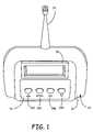
- FIGS. 1 and 2illustrate an energy display module, which can be coupled to a water pit meter, which displays consumption data according to the invention.
- FIG. 3illustrates the energy home module of FIG. 1 with a display of consumption data.
- FIGS. 4A-4Bare examples of a wall repeater adapted for use with the module of FIG. 1 .
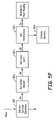
- FIG. 5Ais a block diagram of the operation of the energy home module with an ERT coupled to a utility meter according to the invention.
- FIG. 5Bis a table illustrating operations of corresponding buttons on the energy display module.
- FIG. 5Cis a flow chart illustrating various selectable menu options and sub-menu options programmed in the energy display module.
- FIG. 5Dis a flow chart of an alternate embodiment illustrating various selectable menu options and sub-menu options programmed in the energy display module.
- FIG. 5Eis a block diagram of a utility consumption monitoring network according to the invention.
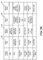
- FIG. 5Fis a flow chart illustrating a delivery services interface menu option and sub-menu options programmed into the energy display module.
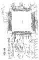
- FIGS. 6A-6Bare schematic diagrams of a display module logic (PCB) board used in connection with the energy display module of FIG. 1 .
- PCBdisplay module logic
- FIG. 6Cis a schematic diagram of real time clock with a battery power back-up and separate crystal according to the invention.
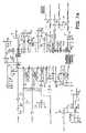
- FIGS. 7A-7Bare schematic diagrams of the radio module illustrated in FIG. 5 used within the display module.
- FIG. 8is a schematic diagram of the keyboard of the module of FIG. 1 .
- the inventionis generally directed to a method and an apparatus for collecting and conveniently displaying real-time data from various utility meter modules (or metering units) by the consumer within the comfort of their own home or business. While the invention is not necessarily limited to such an application, the invention will be better appreciated using a discussion of example embodiments in such a specific context.
- a consumption display module 10is illustrated that is compatible with existing ERTs as well as FCC compliant under the new Part 15.247 digital modulation rules.
- consumption display module 10is comprised of a housing 12 containing a radio module (not shown) that includes a generally low cost receiver and a generally low power transmitter.
- the high power transmittermay be adapted to transmit signals in the 900 Mhz frequency range.
- a transceiver(not shown) may be utilized to increase the portability of consumption display module 10 .
- An antenna 14is connected to the radio module for receiving and transmitting consumption information or data transmitted by the ERT.
- Antenna 14may comprise a whip antenna, a patch antenna, or any other like device that facilitates reception and transmission of the consumption information.
- a keypad 16 and a display panel 18are disposed on or integrated to housing 12 to permit an end user to interface with consumption display module 10 .
- Consumption display (or home display) module 10can also be connected to a Personal Computer (PC) for initial configuration, data extraction or for use as a Real Time data source for external application software.
- PCPersonal Computer
- a plurality of consumption display modules 10display real-time consumption information according to the invention.
- display panel 18is a back-lit Liquid Crystal Display (LCD).
- LCDLiquid Crystal Display
- LEDLight Emitting Diodes
- Consumption display module 10may be adapted to facilitate continuous LCD display of the most recently received consumption data.
- consumption display module 10is shown with a water ERT unit 20 that is adapted to monitor and display, for example, water consumption data on display panel 18 .
- the inventionis not necessarily limited to water meters and can be used in connection with gas and electricity meters that are usually provided to a consumer close to the point of use at the home or business.
- consumption display module 10may include additional Radio Frequency (RF) and/or Power Line Carrier (PLC) inputs to facilitate the transmission of utility consumption information from individual utility consuming appliances, such as pool pumps, hot water heaters, sump pumps and other like devices to energy display module 10 .
- RFRadio Frequency
- PLCPower Line Carrier
- the RF and/or PLC inputsfacilitate communication over a broadband connection and/or provide a radio interface for data communications (or ERT transmitted data), and may allow parameter changes or control of appliances.
- consumption display module 10may also include the capability to interface with Residential Energy Management Systems (REMS), Mobile Data Collection Systems (Mobile), Hand Held Computers (HHC), and Fixed Networks (FN) to facilitate the transmission of utility consumption information. These interfaces also allow head-end calculations as well as tier pricing updates to be transmitted to consumption display module 10 or can be calculated locally.
- REMSResidential Energy Management Systems
- MobileMobile Data Collection Systems
- HHCHand Held Computers
- FNFixed Networks
- the consumption display module of the inventionis configurable to be reset by the reader from the utility traveling in a van after the read is completed. This would start the new monthly billing cycle automatically and without customer intervention.
- the display module's microprocessorcan also be configured to add a smoothing algorithm that would utilize that same customer's historical data to ensure that billing calculations/estimates are not calculated just from the first few days of data from the month, thereby generating an improper estimate. For instance, the customer may exhibit a historical average of 500 gallons of monthly water consumption, but the first day after the meter is read and reset by the utility the customer decides to fill his pool or spa and utilizes 6K-10K gallons of water.
- the microprocessoruses the smoothing algorithm to pull historical water usage data and averages same with the current high usage to level out billing for the rest of the month.
- consumption display module 10has the capability of storing at least one year's worth of 15-minute time-of-use storage data or other forms of data generated by the ERT and/or individually monitored appliances. An end user may utilize keypad 16 and display panel 18 to review the stored time-of-use storage data. Consumption display module 10 may also be capable of sampling energy use on specific feed lines for accurate projection to determine if a feeder upgrade is required. Consumption display module 10 incorporates a full transceiver to accomplish the above functional requirements.
- consumption display module 10is appliance (e.g., refrigerator) mountable where the repeater functionality is extracted and placed nearby (such as in a wall repeater discussed below).
- appliancee.g., refrigerator
- consumption display module 10can now be a magnet-mounted device (or other monitoring systems, such as adhesive or hook and loop fastener systems).
- battery lifecan be extended where intermittent duty cycle is implemented.
- the energy display receiver electronicsmay be integrated into a thermostat housing that retains the thermostat's existing functionality.
- Wall repeater 30provides for improved communication range, reliability and translation of multiband equipment and protocols.
- Wall repeater 30can include at least one outlet cover portion 31 a for detachably coupling to a wall outlet and a repeater housing portion 31 c formed on or coupled to cover portion 31 a for housing a repeater board 32 and antenna.
- Repeater 30facilitates communication between an ERT disposed exterior a home or business, and coupled to a utility meter, and consumption display module 10 .
- Cover portion 31 amay include at least one aperture 31 b extending therethrough for receiving an electric outlet. As illustrated in FIG. 4A , two apertures may extend through cover portion 31 a to accommodate coupling of cover portion 31 a to conventional wall outlets.
- Cover portion 31 amay be detachably couplable to a wall outlet in a manner similar to conventional outlet covers.
- a repeater circuit board 32 of repeater 30may comprise at least one printed digital circuit board capable of propagating and/or amplifying a signal from an ERT.
- An antenna housing portion 31 dmay be formed on or coupled to repeater housing portion 31 c for housing an antenna (not shown) coupled to repeater circuit board 32 .
- antenna housing portion 31 dmay extend along at least a portion of outlet cover portion 31 a.
- Powering wall repeater 30may be accomplished by a plug 40 connected to repeater circuit board 32 or by replaceable or rechargeable batteries housed in repeater housing portion 31 c .
- Wall repeater 30can utilize a normal house 110-volt AC outlet as a mount and can serve as a support for various types of RF transceiving devices.
- the transceiving devicesmay include (but are not limited to) RF to RF, RF to PLC, and RF to infrared communication devices.
- the RF to RF conversionmay include 900 MHz to 1.4 GHz, 900 MHZ to 900 MHZ at increased power, 900 to 2.4 GHZ, 900 to 5.6 GHZ or any combination of these RF bands as well as being bi-directional.
- wall repeater 30provides convenient installation with little customer inconvenience. Additionally, the detachable feature of wall repeater 30 permits it to be easily moved, thereby enabling an end user to adjust a range of reception of utility consumption information by consumption display module 10 .
- wall repeater 30also includes other functional features such as a night-light, fire alarm, energy control motion sensing and burglar alarm motion sensing, by way of example.
- an access panel 33may be removably coupled to a portion of repeater housing portion 31 c for selectively providing access to repeater circuit boards 32 and the antenna. Access panel 33 also may also include at least one opening extending therethrough to provide ventilation and heat dissipation of repeater circuit boards 32 . Access panel 33 provides convenient access for repairs and upgrade of repeater circuit boards 32 and/or antenna.
- the wall repeaterin one embodiment, an assist a sleeve repeater unit that is operably coupled to a metering device to enhance the signal either back to the display module or to one of the intermediate receivers.
- consumption display module 10along with the method of collecting and displaying utility consumption data will be described in more detail.
- FIG. 5Athere is illustrated a block diagram 100 of the operation of consumption display module 110 with an ERT 130 coupled to a utility meter 132 according to the invention.
- consumption display module 110is powered by a power supply 112 , such as an AC wall power supply, that is coupled to regulators 113 which power all of the circuits of consumption display module 110 .
- Consumption display module 110further includes a microprocessor 114 having a radio module 115 (with antenna 124 ) and a keyboard (or keypad) 116 coupled thereto.
- a real time clock 117is also coupled to microprocessor 114 as well as a display panel 118 and a flash memory module 119 .
- battery back-up 120is also included in consumption display module 110 and a connection for a RS232 port 122 for remote PC applications is included.
- Block 140represents the various applications that can interface with consumption display module 110 via port 122 .
- keyboard 116includes a plurality of buttons or actuators ( 140 , 142 , 144 , and 146 ) to permit an end user to interact with any applications or functions of consumption display module 110 .
- the buttonsmay include a menu button 140 or switch for selecting and/or scrolling through various menu and sub-menu options, prompts or cues; an upward 142 and/or downward scroll button 144 to facilitate scrolling through the menu options, and a “Go” or “Enter” button 146 for selecting a particular function from the menu options.
- the table of FIG. 5Billustrates example functions of each of buttons 140 - 146 of keyboard 116 (see also FIG. 1 ).
- selecting or depressing menu button 140may generate a scrollable list of menu prompts or cues on display 118 .
- a usermay then select up or downward scroll buttons 142 , 144 to preview different menu options.
- a usermay select the desired menu option by depressing (ENTER) button 146 .
- depression of (ENTER) button 146displays a sub-menu for the particular menu option selected.
- a useris able to program consumption display module 110 to display various types of information. Examples of the type of information that may be displayed by consumption display module 110 is illustrated in FIGS. 5C-5D . Examples of displayable information may include (but is not limited to) utility cost 150 , utility usage 152 , billing information 154 , set a date to starting monitoring utility consumption 156 , current date and/or time 160 , and/or setting the current date and/or time 162 .
- the method for displaying utility cost information at 150 on consumption display module 110includes depressing menu button 140 to display a menu option for “UTILITY COST” 150 or a similar message. Next, a user may select enter button 146 to set a cost display mode at 151 .
- Various methods of cost displaymay be programmed into consumption display module 110 , such as cost per hour, day, week and/or month. Additional cost display modes are also envisioned within the spirit and scope of the invention.
- consumption display module 110may wait a predetermined amount of time to receive the next incoming consumption information signal from an ERT and/or appliance, wherein it may display a cost of the utility consumed.
- consumption display module 110may be capable of automatically, continuously and/or periodically displaying utility costs.
- energy usage informationmay also be displayed on consumption display module 110 by depressing menu button 140 at least once and then depressing scroll button 144 to scroll through displayed menu options until “UTILITY USAGE” or similar message is displayed.
- a usermay repeatedly depress menu button 140 to scroll through and view various displayed menu options. Once the menu option for UTILITY USAGE 152 is displayed a user may then select enter button 146 to set a utility usage display mode 153 .
- Utility usage display modesinclude utility usage per “kilowatt hour” for electricity, “cubic foot” for water, and “therms” for gas. Other utility usage display modes are also within the spirit and scope of the invention. Similar to the display of utility cost information at 150 , consumption display module 110 may be preprogrammed to automatically display utility usage information at 152 after receiving a consumption information signal from an ERT and/or appliance.
- a useris able to obtain billing information from consumption display module 110 by depressing menu button 140 and/or scroll button 144 to display a menu option for “BILLING INFORMATION” at 154 .
- a usermay then depress ENTER button 146 to display a “NUMBER OF DAYS SINCE START” 155 a sub-menu option.
- Enter button 146may be depressed again to display a “START DATE” 155 b of billing sub-menu option.
- a usermay again depress enter button 146 to display a “BILLING CYCLE INFORMATION” 155 c sub-menu option. Depression of enter button 146 again displays an “ERT ID” 155 d sub-menu option of the ERT currently being monitored.
- Consumption display module 110may redisplay or refresh the billing information after each signal received from an ERT and/or appliance.
- consumption display module 110may be capable of monitoring several ERT and/or appliances in a home or business.
- a usermay be presented with a sub-menu option of “SELECTING AN ERT TYPE” 155 f (see FIG. 5D ) or appliance before viewing other billing information 155 a - e.
- a start date of monitoring one or more ERTs and/or appliancesmay be programmed into consumption display module 110 .
- the following methodmay be used to review and set a monitoring start date.
- a usermay depress menu button 140 and/or scroll button 144 to obtain a menu option for “SETTING A START DATE” at 156 .
- a usermay access sub-menu options “SET THE YEAR” at 157 a , “SET THE MONTH” at 157 b , “SET THE DAY” at 157 c and/or “INITIAL USE” at 157 d by using scroll buttons 142 and 144 to increase and/or decrease values, menu button 140 to select next field or digit and enter button 146 to move between sub-menu options SET THE YEAR at 157 a , SET THE MONTH at 157 b , SET THE DAY at 157 c and/or INITIAL USE at 157 d .
- a usermay be presented with a sub-menu option ACCEPTANCE/REDO at 157 e .
- the usermay select scroll button 142 to accept the start date previously entered or scroll button 144 to redo or reset the set date. If a user selects to reset the start date, the menu options SET THE YEAR at 157 a , SET THE MONTH at 157 b , SET THE DAY at 157 c and/or INITIAL USE at 157 d are automatically re-displayed for user input.
- a usermay be presented with a menu option to “SELECT AN ERT TYPE” at 157 f prior to sub-menu options at 157 a - 157 d . This sub-menu option permits a user to select a particular start date for each ERT and/or appliance being monitored.
- energy module 110may include a menu option “SELECT ERTs AND/OR APPLIANCES TO DISPLAY” at 158 .
- This menu optionpermits a user to set consumption display module 110 to receive a signal from a particular ERT and/or appliance.
- energy module 110may be capable of simultaneously receiving multiple consumption signals from different ERTs and/or appliances.
- a usercan depress menu button 140 until SELECT ERTs TO DISPLAY at 158 menu option is displayed. Depressing enter button 146 again presents a user with sub-menu option “SELECT ERT TYPE” at 159 .
- a usermay scroll through or view various ERT and/or appliances by repeatedly depressing menu button 140 .
- a desired ERT and/or appliancemay be selected by depressing enter button 146 .
- This method of selecting a particular ERT and/or appliance to display on consumption display module 110may be used in other sub-menu options that utilize selecting an ERT and/or appliance to display.
- consumption display module 110also displays a current date and time.
- a menu option “DISPLAY CURRENT DATE AND TIME” at 160is accessible by depressing menu button 140 and/or enter button 146 to cycle through menu options.
- the current date and time at 161is displayed on display 118 . Display of the current date and time is not limited to any particular format and may vary depending upon the user and/or region of use.
- consumption display module 110includes a menu option “SETTING CURRENT DATE AND TIME” at 162 to enable an end user to set a correct date and time for their particular region or location.
- This menu optionis accessible by depressing menu button 140 and/or scroll button 144 to cycle through the menu options. Depressing enter button 146 causes consumption display module 110 to display sub-menu options “SET THE YEAR” at 163 a , “SET THE MONTH” at 163 b , “SET THE DAY” at 163 c , “SET THE HOUR” at 163 d , and “SET THE MINUTE” at 163 e .
- the year, month, day, hour and minutesmay be modified by depressing menu button 140 , scroll buttons 142 and 144 and/or enter button 146 .
- An end usermay move between sub-menu options 163 a - 163 e by depressing menu button 140 and/or enter button 146 .
- Once the date and time have been entered an end usermay depress enter button 146 , wherein the current date and time are displayed on consumption display module 110 .
- Consumption display module 110is also configurable to listen for one unique Water ERT, one unique Gas ERT, and one unique Electric ERT. Consumption display module 110 can be configured to effectively filter out all other ERT transmissions that it receives. This allows consumption display module 110 to focus its data gathering effort on all of the energy utilized for a specific building or home and to display these three consumptions on the LCD or display 118 by scrolling the information for the user. In contrast to this feature, consumption display module 110 can also report all of the ERT transmissions that it receives through its serial port allowing consumption display module 110 to become a data collection center for nearby ERTs. This is important with regards to ERT discrimination for focusing on a specific energy source. A user can access energy consumption information of each appliance by the method described above. Additionally, a repeater may also be used to propagate an energy consumption signal of appliances a distance away from consumption display module 110 .
- consumption display module 110is capable of monitoring and/or sub-metering one or more appliances within a house or business.
- Consumption display module 110may be capable of monitoring utility consumption by electric heat sources such as furnaces, baseboard heaters and like devices. Other electrical energy consuming devices that can be monitored include electric hot water heaters, electric dryers, electric pool pumps, sump pumps, air conditioners or central air devices, and/or whole house or building fan systems.
- consumption display module 110can monitor indoor and outdoor water consumption.
- energy module 110can monitor gas consumption of ranges, stoves and/or ovens, clothes dryers, gas water heaters and/or furnaces.
- consumption display module 110can monitor electric, gas and/or water consumption of particular machines or departments within the facility.
- a utility consumption-monitoring network (“ECNM”) 170can be utilized to monitor utility consumption by one or more appliances.
- ECNM 170can use an ERT or similar device placed in communication with each appliance being monitored. Each ERT would then transmit utility consumption information to consumption display module 110 for display to the end user.
- major appliance manufacturersare currently considering the implementation of Bluetooth and Wi-Fi connectivity to the Internet. The functionality of these types of functions and devices lends itself to utilization with ECNM 170 without substantial system reconfiguration.
- REMS and consumption display module 110can easily provide this capability by utilizing a translator function (Bluetooth to 900 MHz, Wi-Fi to 900 MHz or alternatively 1.4 GHz).
- consumption display module 110can measure and monitor internal and/or external environmental parameters such as house or building temperature, attic temperature, outside temperature, wind direction and/or speed, humidity, and other like parameters. Consumption display module 110 can then correlate the environmental parameters and utility consumption measurements of each or all of the utilities monitored. Consumption display module 110 can also correlate environmental parameters with the energy consumption of a particular appliance. By correlating the environmental parameters and utility consumption an end user may be able to predict or forecast utility consumption or utilization and adjust their usage accordingly.
- internal and/or external environmental parameterssuch as house or building temperature, attic temperature, outside temperature, wind direction and/or speed, humidity, and other like parameters.
- Consumption display module 110can then correlate the environmental parameters and utility consumption measurements of each or all of the utilities monitored. Consumption display module 110 can also correlate environmental parameters with the energy consumption of a particular appliance. By correlating the environmental parameters and utility consumption an end user may be able to predict or forecast utility consumption or utilization and adjust their usage accordingly.
- consumption display module 110may include a menu option for “DELIVERY SERVICES INTERFACE” 180 that is accessible by the methods described above.
- DELIVERY SERVICES INTERFACEUpon the delivery of a utility such as propane or oil, an end user may access DELIVERY SERVICES INTERFACE at 180 and select enter button 146 to access sub-menu option “INITIAL ENERGY AMOUNT” at 181 a to set an amount of utility delivered.
- an end useraccess sub-menu “LOWER LIMIT” 181 b and “NOTIFICATION” 181 c , to set a lower limit or level of utility such that consumption display module 110 can notify an end user when the utility utilized reaches the set lower limit.
- consumption display module 110can initiate delivery 181 d of additional utility upon detection of the set lower limit.
- Consumption display module 110can utilize Bluetooth and/or Wi-Fi technology to connect to the Internet and place the order.
- Consumption display module 110can also include an alarm, warning or notification mechanism for notifying an end user of a particular event or events.
- consumption display module 110can notify an end user of excessive utility consumption, which can be an indicator of water leakage, gas leakage and/or electricity theft.
- Consumption display module 110can determine excess utility consumption by determining a utility utilization upper limit during off peak times and notifying an end user if the upper limit is exceeded.
- Consumption display module 110can also notify an end user if a pricing tier or block level is exceeded, thereby permitting an end user to reduce usage of a particular utility and/or switch to an alternative utility.
- Consumption display module 110can also notify an end user if the total utility cost approaches or exceeds a preset limit. Preset limits can be manually programmed into consumption display module 110 by the methods described previously.
- Consumption display module 110includes at least one software program adapted to present data gathered from ERT and similar devices.
- the at least one software programis configurable to display actual utilization, prediction of energy consumption, year to date and comparison with last year, dollars spent, identify greatest consumption and expense associated with specific devices, “what if” predictor of utilization, correlation with utility billing information, acceptance of actual billing data from utility, correlation with weather data, acceptance of weather information and graphical presentation of utilization and/or data gathered.
- the software programcan be preloaded or preprogrammed at the time of manufacture or can be updated remotely via transmissions from the utility company.
- FIGS. 6A-6Billustrate schematic diagrams of the logic boards within module 10 .
- FIG. 6Cis a schematic diagram of the real time clock with battery power back up and separate crystal.
- these figuresillustrate the Texas Instrument Microprocessor MSP430F149 (U 28 ), with JTAG programming connection (J 11 ), connections to the Liquid Crystal Display (J 5 and J 3 ) and connections to the radio transceiver board described in FIGS. 7A and 7B (J 15 ).
- power supply regulatorsU 30 and U 27
- the microprocessorcontains the application software in its internal FLASH memory. This device controls the operation of the Home Display. Packet data is managed and verified by the microprocessor.
- the transceiver( FIGS. 7A and 7B ) is controlled through a serial SPI bus by the microprocessor.
- FIG. 6Billustrates a Field Programmable Logic Array (FPGA, EP1K50QC208-3, U 20 ) with a serial flash configuration memory (EPC2LC20, U 19 ) and a JTAG connection (J 7 ).
- the FPGAis placed in the path between the microprocessor and the radio transceiver board (see FIGS. 7A and 7B ), and decodes the Manchester encoded data stream from the radio board for use by the microprocessor.
- receive datais buffered within the FPGA for subsequent retrieval by the microprocessor.
- the FPGAreceives serial data from the microprocessor, converts it to Manchester encoded data and controls the OOK (ON OFF KEYED) modulation of the transmitter. Transmit power control is also performed by the FPGA.
- the microprocessorcommunicates with the FPGA over a serial SPI bus for data transfers, and power settings.
- FIG. 6Cillustrates an MSP430F1121 microprocessor (U 38 ) and its 32 KHz crystal (Y 9 ), backup battery (BT 1 ), and connections to the main microprocessor ( FIG. 6A ).
- This support microprocessor (U 38 )maintains in its memory date and time information and performs as a continuous source of real time clock and calendar information for the main microprocessor ( FIG. 6A ).
- FIGS. 7A-7Bare schematic diagrams of the radio module illustrated in FIG. 5 used within module 10 of the present invention.
- FIG. 7Aillustrates includes the Philips UAA3515A RF ASIC (U 7 ) which is a transceiver application specific integrated circuit (ASIC) and voltage regulator (U 1 ). This part contains the majority of the radio transmit and receive circuitry.
- the UAA3515Acommunicates with the microprocessor over a serial SPI bus (Pins 3 , 4 , and 5 of J 2 FIG. 7B ).
- the UAA3515Aresponds to set up and frequency control information from the microprocessor.
- FIG. 7Billustrates the circuitry between the antenna and the RF ASIC along with providing connections to the main printed circuit board via connector (J 2 ).
- FIG. 7Balso provides RSSI signal buffering (U 9 ), a data slicer (U 10 ) and Intermediate Frequency (IF) filtering of the received signal (Filter 1 and Filter 2 ).
- the received data from the data slicerleaves the transceiver board on J 2 and is connected to the FPGA which resides in FIG. 6B .
- the power amplifier (U 6 ), antenna switch (U 2 ), SAW (FL 1 ), and low noise amplifier (LNA, U 3 )are also included on this figure.
- the antenna switchselects either receive or transmit mode. When operating in transmit mode the power amplifier boosts the transmit signal destined for the antenna.
- the SAW and discrete filtering componentsWhen operating in receive mode, reject unwanted signals before arriving at the LNA.
- the LNAincreases the signal level for use by the UAA3515 RF ASIC.
- the SAW and discrete filtering componentsreject out of band, undesired signals before arriving at the UAA3515A.
- the intermediate frequency filtersare connected directly to the RF ASIC in FIG. 7A and provide receiver filtering that occurs within the RF ASIC.
- FIG. 8is a schematic diagram of the keyboard of module 10 of FIG. 1 .
- the 4 push buttons available to the operator on the front of the unit of this embodimentallow the operator to change modes, adjust parameters, reset registers, and request additional information that is kept in the memory of the microprocessor.
- the push buttons along with the LCD displayprovide the user interface for the display module.
- the display moduleis configurable to receive data directly from the ERT where the ERT has high power levels, such as a 1.4 GHz version for the water pit ERT version. Also periodic transmissions from the water pit ERT can be coordinated with the display module collection mode to increase reliability in gathering data. This would provide flexibility and lower cost in locating the display module since the wall repeater would not be necessary. In other embodiments of the display module, the wall repeater would be interposed with the display module and the water pit ERT to ensure data collection in instances were the water pit ERT is located a fair distance from the display module and the ERT signal is weaker.
- the consumption display moduleis simplified in its design to include a single frequency radio receiver, an inexpensive microprocessor, a small capacity memory for minor data storage and an inexpensive display, all intended to operate on battery power, so as to generate an inexpensive module.
- the modulemay also include a minor feature of collecting and displaying small amounts of information as directed by the consumer, similar to a trip odometer in automotive applications.
- the display modulecan be fitted with a magnet or a hook and fastener type system to facilitate location on a kitchen appliance for ease of use and viewing.
- the display modulecan be fitted with a battery to also facilitate location on a kitchen appliance or other location in the home for ease of use and viewing.
- the microprocessor of the display modulecan be configured to include a leak detection algorithm or scheme, such as described in U.S. Patent Application, entitled “Passive Consumptive Leak Detection”, having U.S. patent application Ser. No. 10/965,283, filed on Oct. 14, 2004, which hereby incorporated by reference in its entirety.
- the display moduleis able to take data provided by the water meter ERT and determine if there is a leak by continuous and low quantity of water usage, such as when a toilet is leaking or a faucet is leaking somewhere on the premises. Also the time of day usage is also a clue that there may be a leak, especially where the water meter ERT is generating data in the middle of the night or when everyone is on vacation.
- the electronics of consumption display module 110can be applied to automotive diagnostics and consumables.
- the displaycould communicate with the personnel vehicle to relay information on the status of the car. Things that could be communicated might be fuel level, maintenance related functions such as oil change, intermittent sensors, warranty recalls and general health of the vehicle. We also mentioned a data repository of the homeowner that he or she can take with them. In general all information that is available from the on board computer can be communicated to the consumption display module 110 . Further, in a fixed network application, this information can be forwarded through the system to a head end or in the case of REMS, directly into the Internet for direct connection to the appropriate service department.
Landscapes
- Business, Economics & Management (AREA)
- Physics & Mathematics (AREA)
- General Physics & Mathematics (AREA)
- Engineering & Computer Science (AREA)
- Health & Medical Sciences (AREA)
- Economics (AREA)
- Marketing (AREA)
- Tourism & Hospitality (AREA)
- General Health & Medical Sciences (AREA)
- Human Resources & Organizations (AREA)
- Public Health (AREA)
- Primary Health Care (AREA)
- Strategic Management (AREA)
- Water Supply & Treatment (AREA)
- General Business, Economics & Management (AREA)
- Theoretical Computer Science (AREA)
- Emergency Management (AREA)
- Computer Networks & Wireless Communication (AREA)
- Selective Calling Equipment (AREA)
- Arrangements For Transmission Of Measured Signals (AREA)
- Mobile Radio Communication Systems (AREA)
Abstract
Description
Claims (41)
Priority Applications (3)
| Application Number | Priority Date | Filing Date | Title |
|---|---|---|---|
| US11/036,170US7317404B2 (en) | 2004-01-14 | 2005-01-13 | Method and apparatus for collecting and displaying consumption data from a meter reading system |
| US11/985,337US20080180274A1 (en) | 2004-01-14 | 2007-11-14 | Method and apparatus for collecting and displaying consumption data a from a meter reading system |
| US13/092,492US20110210862A1 (en) | 2004-01-14 | 2011-04-22 | Method and apparatus for collecting and displaying consumption data from a meter reading system |
Applications Claiming Priority (2)
| Application Number | Priority Date | Filing Date | Title |
|---|---|---|---|
| US53641904P | 2004-01-14 | 2004-01-14 | |
| US11/036,170US7317404B2 (en) | 2004-01-14 | 2005-01-13 | Method and apparatus for collecting and displaying consumption data from a meter reading system |
Related Child Applications (1)
| Application Number | Title | Priority Date | Filing Date |
|---|---|---|---|
| US11/985,337ContinuationUS20080180274A1 (en) | 2004-01-14 | 2007-11-14 | Method and apparatus for collecting and displaying consumption data a from a meter reading system |
Publications (2)
| Publication Number | Publication Date |
|---|---|
| US20050190074A1 US20050190074A1 (en) | 2005-09-01 |
| US7317404B2true US7317404B2 (en) | 2008-01-08 |
Family
ID=34807012
Family Applications (3)
| Application Number | Title | Priority Date | Filing Date |
|---|---|---|---|
| US11/036,170Expired - LifetimeUS7317404B2 (en) | 2004-01-14 | 2005-01-13 | Method and apparatus for collecting and displaying consumption data from a meter reading system |
| US11/985,337AbandonedUS20080180274A1 (en) | 2004-01-14 | 2007-11-14 | Method and apparatus for collecting and displaying consumption data a from a meter reading system |
| US13/092,492AbandonedUS20110210862A1 (en) | 2004-01-14 | 2011-04-22 | Method and apparatus for collecting and displaying consumption data from a meter reading system |
Family Applications After (2)
| Application Number | Title | Priority Date | Filing Date |
|---|---|---|---|
| US11/985,337AbandonedUS20080180274A1 (en) | 2004-01-14 | 2007-11-14 | Method and apparatus for collecting and displaying consumption data a from a meter reading system |
| US13/092,492AbandonedUS20110210862A1 (en) | 2004-01-14 | 2011-04-22 | Method and apparatus for collecting and displaying consumption data from a meter reading system |
Country Status (4)
| Country | Link |
|---|---|
| US (3) | US7317404B2 (en) |
| AU (1) | AU2005200227C1 (en) |
| CA (1) | CA2492822C (en) |
| MX (1) | MXPA05000702A (en) |
Cited By (89)
| Publication number | Priority date | Publication date | Assignee | Title |
|---|---|---|---|---|
| US20070139220A1 (en)* | 2005-12-19 | 2007-06-21 | General Electric Company | Method and system for metering consumption of energy |
| US20070203860A1 (en)* | 2006-02-24 | 2007-08-30 | Gridpoint, Inc. | Energy budget manager |
| US20070239317A1 (en)* | 2006-04-07 | 2007-10-11 | Bogolea Bradley D | Artificial-Intelligence-Based Energy Auditing, Monitoring and Control |
| US20080117077A1 (en)* | 2006-06-20 | 2008-05-22 | Ovidiu Ratiu | Automatic Meter Reading Communication |
| US20080136667A1 (en)* | 1999-02-23 | 2008-06-12 | Raj Vaswani | Network for automated meter reading |
| US20080224892A1 (en)* | 2007-03-16 | 2008-09-18 | I-Conserve, Llc | System and method for monitoring and estimating energy resource consumption |
| US20080238712A1 (en)* | 2007-04-02 | 2008-10-02 | Square D Company | Remote display chain for mutiple user interface applications |
| US20090009359A1 (en)* | 2007-07-05 | 2009-01-08 | Lsi Corporation | Method of Monitoring Commodity Consumption |
| US20090135018A1 (en)* | 2007-11-25 | 2009-05-28 | Michel Veillette | System and method for false alert filtering of event messages within a network |
| US20090138099A1 (en)* | 2007-11-25 | 2009-05-28 | Michel Veillette | Energy use control system and method |
| US20090135836A1 (en)* | 2007-11-25 | 2009-05-28 | Michel Veillette | Collector device and system utilizing standardized utility metering protocol |
| US20090135753A1 (en)* | 2007-11-25 | 2009-05-28 | Michel Veillette | Power-conserving network device for advanced metering infrastructure |
| US20090138713A1 (en)* | 2007-11-25 | 2009-05-28 | Michel Veillette | Proxy use within a mesh network |
| US20090138777A1 (en)* | 2007-11-25 | 2009-05-28 | Michel Veillette | System and method for power outage and restoration notification in an advanced metering infrastructure network |
| US20090138866A1 (en)* | 2007-11-25 | 2009-05-28 | Michel Veillette | Upgrade process system and method |
| US20090153357A1 (en)* | 2007-10-25 | 2009-06-18 | Trilliant Networks, Inc. | Gas meter having ultra-sensitive magnetic material retrofitted onto meter dial and method for performing meter retrofit |
| US20090167547A1 (en)* | 2007-12-31 | 2009-07-02 | Brad Gilbert | Utility disconnect monitor node with communication interface |
| US20090256719A1 (en)* | 2008-04-14 | 2009-10-15 | Dave Boissonneault | Utility monitoring system |
| US20090309756A1 (en)* | 2008-06-13 | 2009-12-17 | Elster Electricity, Llc | Techniques For Limiting Demand From An electricity Meter With An Installed Relay |
| US20090315535A1 (en)* | 2008-06-20 | 2009-12-24 | Lee Jr Robert Edward | Method and system for detecting electricity theft |
| US20090326725A1 (en)* | 2008-05-19 | 2009-12-31 | Michael James Carlson | Managing Electric Power Consumption |
| US20100007655A1 (en)* | 2008-06-06 | 2010-01-14 | Black & Decker Inc. | Energy usage display device |
| US20100045471A1 (en)* | 2008-08-19 | 2010-02-25 | Meyers Timothy Meyer | Leak detection and control system and mehtod |
| US20100100253A1 (en)* | 2008-04-17 | 2010-04-22 | Demi Energy, Inc. | Systems and Methods for Controlling Energy Consumption |
| US20100110077A1 (en)* | 2008-11-06 | 2010-05-06 | Gary Grossman | System and method for identifying power usage issues |
| USD615895S1 (en)* | 2008-12-23 | 2010-05-18 | Utility Metering Services Limited | Energy consumption display |
| US20100127889A1 (en)* | 2008-11-21 | 2010-05-27 | William Steven Vogel | Methods and systems for virtual energy management display |
| US20100191487A1 (en)* | 2009-01-26 | 2010-07-29 | Geneva Clean Tech Inc. | Energy usage monitoring with remote display and automatic detection of appliance including graphical user interface |
| US20100231413A1 (en)* | 2009-03-11 | 2010-09-16 | Trilliant Networks, Inc. | Process, device and system for mapping transformers to meters and locating non-technical line losses |
| US20100286840A1 (en)* | 2009-05-07 | 2010-11-11 | Powell Phillip W | Voltage conservation using advanced metering infrastructure and substation centralized voltage control |
| US20100292961A1 (en)* | 2009-05-15 | 2010-11-18 | David Moss | Wireless tracking device for tracking appliance usage and modifying user behavior |
| US20100299457A1 (en)* | 2009-05-22 | 2010-11-25 | Itron, Inc. | Time synchronization of portable devices |
| US20110040785A1 (en)* | 2008-05-07 | 2011-02-17 | PowerHouse dynamics, Inc. | System and method to monitor and manage performance of appliances |
| US20110077037A1 (en)* | 2009-09-28 | 2011-03-31 | Itron, Inc. | Methodology and apparatus for validating network coverage |
| US20110148202A1 (en)* | 2009-01-26 | 2011-06-23 | Geneva Cleantech Inc. | Methods and apparatus for power factor correction and reduction of distortion in and noise in a power supply delivery network |
| US20110298635A1 (en)* | 2010-06-04 | 2011-12-08 | Bernie Yip | Self dynamo smart flow utility meter and system for flow utility real-time flow usage monitoring and control, self error and leakages monitoring |
| US20120053902A1 (en)* | 2006-09-15 | 2012-03-01 | Itron, Inc. | Distributing metering responses for load balancing an amr network |
| US20120101652A1 (en)* | 2010-10-25 | 2012-04-26 | Samsung Electronics Co., Ltd. | Power management apparatus, power management system including the power management apparatus, and method for controlling the power management system |
| USD667321S1 (en)* | 2011-01-21 | 2012-09-18 | Yokogawa Electric Corporation | Temperature transmitter |
| US8269650B2 (en) | 2010-04-14 | 2012-09-18 | Itron, Inc. | Meter right sizing |
| US20120310801A1 (en)* | 2009-11-27 | 2012-12-06 | Kabushiki Kaisha Toshiba | Power usage calculation system |
| US8502640B2 (en) | 2007-11-25 | 2013-08-06 | Trilliant Networks, Inc. | System and method for transmitting and receiving information on a neighborhood area network |
| US8560134B1 (en) | 2010-09-10 | 2013-10-15 | Kwangduk Douglas Lee | System and method for electric load recognition from centrally monitored power signal and its application to home energy management |
| US8699377B2 (en) | 2008-09-04 | 2014-04-15 | Trilliant Networks, Inc. | System and method for implementing mesh network communications using a mesh network protocol |
| US8832428B2 (en) | 2010-11-15 | 2014-09-09 | Trilliant Holdings Inc. | System and method for securely communicating across multiple networks using a single radio |
| US20140267296A1 (en)* | 2013-03-15 | 2014-09-18 | Fluke Corporation | Automated Combined Display of Measurement Data |
| US8842712B2 (en) | 2011-03-24 | 2014-09-23 | Gregory C. Hancock | Methods and apparatuses for reception of frequency-hopping spread spectrum radio transmissions |
| US8856323B2 (en) | 2011-02-10 | 2014-10-07 | Trilliant Holdings, Inc. | Device and method for facilitating secure communications over a cellular network |
| US8891338B2 (en) | 2009-01-29 | 2014-11-18 | Itron, Inc. | Measuring the accuracy of an endpoint clock from a remote device |
| US20140343734A1 (en)* | 2012-01-26 | 2014-11-20 | Timothy Meyer | Substance control system |
| US20140343736A1 (en)* | 2012-01-26 | 2014-11-20 | Timothy Meyer | Substance Control System |
| US8970394B2 (en) | 2011-01-25 | 2015-03-03 | Trilliant Holdings Inc. | Aggregated real-time power outages/restoration reporting (RTPOR) in a secure mesh network |
| US9001787B1 (en) | 2011-09-20 | 2015-04-07 | Trilliant Networks Inc. | System and method for implementing handover of a hybrid communications module |
| US9013173B2 (en) | 2010-09-13 | 2015-04-21 | Trilliant Networks, Inc. | Process for detecting energy theft |
| US9019120B2 (en)* | 2010-11-09 | 2015-04-28 | General Electric Company | Energy manager—water leak detection |
| US9041349B2 (en) | 2011-03-08 | 2015-05-26 | Trilliant Networks, Inc. | System and method for managing load distribution across a power grid |
| US9084120B2 (en) | 2010-08-27 | 2015-07-14 | Trilliant Networks Inc. | System and method for interference free operation of co-located transceivers |
| US20150295408A1 (en)* | 2008-09-30 | 2015-10-15 | Google Inc. | Systems, methods and apparatus for encouraging energy conscious behavior based on aggregated third party energy consumption |
| US9197949B2 (en) | 2010-12-02 | 2015-11-24 | Tenrehte Technologies, Inc. | Self-organizing multiple appliance network connectivity apparatus for controlling plurality of appliances |
| US9228853B1 (en) | 2012-06-25 | 2016-01-05 | Neptune Technology Group Inc. | Method of computing quantity of unaccounted for water in water distribution |
| US9282383B2 (en) | 2011-01-14 | 2016-03-08 | Trilliant Incorporated | Process, device and system for volt/VAR optimization |
| US9325174B2 (en) | 2013-03-15 | 2016-04-26 | Dominion Resources, Inc. | Management of energy demand and energy efficiency savings from voltage optimization on electric power systems using AMI-based data analysis |
| US9354641B2 (en) | 2013-03-15 | 2016-05-31 | Dominion Resources, Inc. | Electric power system control with planning of energy demand and energy efficiency using AMI-based data analysis |
| US9367075B1 (en) | 2013-03-15 | 2016-06-14 | Dominion Resources, Inc. | Maximizing of energy delivery system compatibility with voltage optimization using AMI-based data control and analysis |
| US9454173B2 (en) | 2013-05-22 | 2016-09-27 | Utility Programs And Metering Ii, Inc. | Predictive alert system for building energy management |
| US20160350734A1 (en)* | 2014-06-01 | 2016-12-01 | Gideon Samid | Versatile, Real Time, Two-Ways Payment for Power and Utilities |
| US9563218B2 (en) | 2013-03-15 | 2017-02-07 | Dominion Resources, Inc. | Electric power system control with measurement of energy demand and energy efficiency using t-distributions |
| US9766270B2 (en) | 2013-12-30 | 2017-09-19 | Fluke Corporation | Wireless test measurement |
| US9847639B2 (en) | 2013-03-15 | 2017-12-19 | Dominion Energy, Inc. | Electric power system control with measurement of energy demand and energy efficiency |
| US9857805B2 (en) | 2013-02-18 | 2018-01-02 | Flo Technologies, Inc. | Fluid monitoring and control system |
| US10095659B2 (en) | 2012-08-03 | 2018-10-09 | Fluke Corporation | Handheld devices, systems, and methods for measuring parameters |
| US10177930B1 (en) | 2016-03-07 | 2019-01-08 | Wells Fargo Bank, N.A. | Smart thermostat control system |
| US10401401B2 (en) | 2014-03-31 | 2019-09-03 | Panoramic Power Ltd. | System and methods thereof for monitoring of energy consumption cycles |
| US10527516B2 (en) | 2017-11-20 | 2020-01-07 | Phyn Llc | Passive leak detection for building water supply |
| US10732656B2 (en) | 2015-08-24 | 2020-08-04 | Dominion Energy, Inc. | Systems and methods for stabilizer control |
| US10962993B2 (en) | 2013-02-18 | 2021-03-30 | Flo Technologies, Inc. | Manual control for actuated fluid monitoring and control device |
| US11055400B2 (en) | 2018-07-13 | 2021-07-06 | Bank Of America Corporation | Monitoring data consumption in an application testing environment |
| US11138056B2 (en) | 2016-01-03 | 2021-10-05 | Aktiebolaget Skf | System and method for unsupervised prediction of machine failures |
| US11201395B2 (en) | 2019-09-09 | 2021-12-14 | Honeywell International Inc. | Camouflaged single branch dual band antenna for use with power meter |
| US11237574B2 (en) | 2013-02-18 | 2022-02-01 | Flo Technologies, Inc. | Fluid monitoring and control system |
| US11243524B2 (en) | 2016-02-09 | 2022-02-08 | Presenso, Ltd. | System and method for unsupervised root cause analysis of machine failures |
| US11280651B2 (en) | 2019-03-25 | 2022-03-22 | Flo Technologies, Inc. | Thin film thermal mass flow sensor in fluid applications |
| US11403551B2 (en) | 2016-01-10 | 2022-08-02 | Presenso, Ltd. | System and method for validating unsupervised machine learning models |
| US20230003605A1 (en)* | 2018-10-31 | 2023-01-05 | The Detection Group, Inc. | System and method for wireless water leak detection |
| US11624636B2 (en) | 2019-05-07 | 2023-04-11 | Fortune Brands Water Innovations LLC | Turbine design for flow meter |
| US11669083B2 (en) | 2018-11-27 | 2023-06-06 | Aktiebolaget Skf | System and method for proactive repair of sub optimal operation of a machine |
| US11933695B2 (en) | 2018-12-26 | 2024-03-19 | Aktiebolaget Skf | System and method for detecting anomalies in sensory data of industrial machines located within a predetermined proximity |
| US12029172B1 (en) | 2023-01-07 | 2024-07-09 | Lumo, Inc. | Water control device for agriculture |
| US12431621B2 (en) | 2023-01-26 | 2025-09-30 | Honeywell International Inc. | Compact dual band antenna |
Families Citing this family (62)
| Publication number | Priority date | Publication date | Assignee | Title |
|---|---|---|---|---|
| US7385524B1 (en) | 2001-09-21 | 2008-06-10 | James Robert Orlosky | Automated meter reading, billing and payment processing system |
| US9520005B2 (en)* | 2003-07-24 | 2016-12-13 | Verizon Telematics Inc. | Wireless vehicle-monitoring system |
| US7379791B2 (en)* | 2004-08-03 | 2008-05-27 | Uscl Corporation | Integrated metrology systems and information and control apparatus for interaction with integrated metrology systems |
| FI20050501L (en)* | 2005-05-11 | 2006-11-12 | Valtion Teknillinen | Remote sensor system and method and use of remote sensor |
| JP4732056B2 (en)* | 2005-07-29 | 2011-07-27 | 本田技研工業株式会社 | Vehicle control device |
| CA2626283A1 (en)* | 2005-10-20 | 2007-04-26 | Itron, Inc. | Automatic detection of unusual consumption by a utility meter |
| US7427927B2 (en)* | 2006-02-16 | 2008-09-23 | Elster Electricity, Llc | In-home display communicates with a fixed network meter reading system |
| US20070214070A1 (en)* | 2006-03-06 | 2007-09-13 | Paul Donahue | Water conditioner device |
| US7885917B2 (en)* | 2006-05-26 | 2011-02-08 | Board Of Regents Of The Nevada System Of Higher Education, On Behalf Of The Desert Research Institute | Utility monitoring and disaggregation systems and methods of use |
| GB2440961A (en)* | 2006-05-30 | 2008-02-20 | Save Energy Plc 2 | Wireless monitoring of utility usage within the home |
| US8063792B2 (en)* | 2006-09-18 | 2011-11-22 | Neptune Technology Group, Inc. | Field service and meter reading devices with GPS functionality |
| US20080154802A1 (en)* | 2006-11-29 | 2008-06-26 | Chalupsky Larry K | Utility product usage internet access |
| KR101455161B1 (en)* | 2007-01-08 | 2014-10-28 | 톰슨 라이센싱 | Methods and apparatus for video stream splicing |
| NZ579331A (en)* | 2007-02-02 | 2012-12-21 | Aztech Associates Inc | Utility monitoring device, system and method |
| US9852486B2 (en) | 2007-02-02 | 2017-12-26 | Aztech Associates Inc. | Utility monitoring device, system and method |
| GB0709893D0 (en)* | 2007-05-23 | 2007-07-04 | Onzo Ltd | Apparatus for monitoring rescue consumption |
| WO2009082761A1 (en)* | 2007-12-26 | 2009-07-02 | Elster Electricity, Llc. | Optimized data collection in a wireless fixed network metering system |
| GB2460301A (en)* | 2008-05-30 | 2009-12-02 | Pulsar Process Measurement Ltd | Sump monitoring method and apparatus |
| US8843242B2 (en) | 2008-09-15 | 2014-09-23 | General Electric Company | System and method for minimizing consumer impact during demand responses |
| US8548638B2 (en)* | 2008-09-15 | 2013-10-01 | General Electric Company | Energy management system and method |
| US8803040B2 (en) | 2008-09-15 | 2014-08-12 | General Electric Company | Load shedding for surface heating units on electromechanically controlled cooking appliances |
| WO2010031029A1 (en) | 2008-09-15 | 2010-03-18 | General Electric Company | Energy management of clothes dryer appliance |
| US8541719B2 (en) | 2008-09-15 | 2013-09-24 | General Electric Company | System for reduced peak power consumption by a cooking appliance |
| US9303878B2 (en) | 2008-09-15 | 2016-04-05 | General Electric Company | Hybrid range and method of use thereof |
| GB2465800A (en)* | 2008-12-01 | 2010-06-02 | Joyce Foster | Utility Consumption Apparatus |
| US20100207728A1 (en)* | 2009-02-18 | 2010-08-19 | General Electric Corporation | Energy management |
| US8869569B2 (en) | 2009-09-15 | 2014-10-28 | General Electric Company | Clothes washer demand response with at least one additional spin cycle |
| US8943857B2 (en) | 2009-09-15 | 2015-02-03 | General Electric Company | Clothes washer demand response by duty cycling the heater and/or the mechanical action |
| US8943845B2 (en) | 2009-09-15 | 2015-02-03 | General Electric Company | Window air conditioner demand supply management response |
| US8522579B2 (en) | 2009-09-15 | 2013-09-03 | General Electric Company | Clothes washer demand response with dual wattage or auxiliary heater |
| GB2476456B (en) | 2009-12-18 | 2013-06-19 | Onzo Ltd | Utility data processing system |
| GB2477366B (en) | 2009-11-12 | 2013-06-19 | Onzo Ltd | Data storage and transfer |
| KR20110069574A (en)* | 2009-12-17 | 2011-06-23 | 엘지전자 주식회사 | A control method for an electric appliance having a detachable communication modem |
| US7920983B1 (en)* | 2010-03-04 | 2011-04-05 | TaKaDu Ltd. | System and method for monitoring resources in a water utility network |
| CA2734881A1 (en)* | 2010-03-19 | 2011-09-19 | Marlex Engineering Inc. | Electricity usage planner |
| KR101708028B1 (en)* | 2010-04-13 | 2017-02-20 | 삼성전자주식회사 | Method and apparatus of displaying consumption power |
| US20110282808A1 (en)* | 2010-05-17 | 2011-11-17 | Ennovationz, Inc. | Utility consumption recommendation |
| US8719186B2 (en) | 2010-05-17 | 2014-05-06 | Ennovationz Inc. | Historical utility consumption disaggregation |
| US8909494B2 (en) | 2010-06-25 | 2014-12-09 | Lorden Oil Company, Inc. | Self calibrating home site fuel usage monitoring device and system |
| US20110125337A1 (en)* | 2010-08-30 | 2011-05-26 | Vyacheslav Zavadsky | Household appliance adapted to work with time of use electricity rates |
| US8801862B2 (en) | 2010-09-27 | 2014-08-12 | General Electric Company | Dishwasher auto hot start and DSM |
| GB201017861D0 (en)* | 2010-10-22 | 2010-12-01 | Cooper Stuart D | Projected display energy meter |
| US20120166233A1 (en)* | 2010-12-22 | 2012-06-28 | Alcatel-Lucent Usa Inc. | Method And Apparatus For Enhancing Consumer Awareness Of Utility Consumption And Cost Data |
| EP2666062A1 (en)* | 2011-01-18 | 2013-11-27 | Zodiac Pool Systems, Inc. | Remotely controlling aspects of pools and spas |
| US8583386B2 (en) | 2011-01-18 | 2013-11-12 | TaKaDu Ltd. | System and method for identifying likely geographical locations of anomalies in a water utility network |
| JP6109066B2 (en)* | 2011-02-28 | 2017-04-05 | 横河電機株式会社 | Energy management method |
| EP2686643A4 (en) | 2011-03-18 | 2014-09-10 | Soneter Llc | Methods and apparatus for fluid flow measurement |
| CN102184630A (en)* | 2011-05-09 | 2011-09-14 | 广州从兴电子开发有限公司 | Data acquisition concentrator and data acquisition method |
| GB2491109B (en) | 2011-05-18 | 2014-02-26 | Onzo Ltd | Identification of a utility consumption event |
| US8341106B1 (en) | 2011-12-07 | 2012-12-25 | TaKaDu Ltd. | System and method for identifying related events in a resource network monitoring system |
| US9053519B2 (en) | 2012-02-13 | 2015-06-09 | TaKaDu Ltd. | System and method for analyzing GIS data to improve operation and monitoring of water distribution networks |
| US10242414B2 (en) | 2012-06-12 | 2019-03-26 | TaKaDu Ltd. | Method for locating a leak in a fluid network |
| US8912919B2 (en)* | 2013-01-15 | 2014-12-16 | Tata Consultancy Services Limited | Determination of resource consumption |
| US20150163945A1 (en) | 2013-12-11 | 2015-06-11 | Honeywell International Inc. | Hvac controller with thermistor biased against an outer housing |
| JP5930225B2 (en)* | 2014-01-27 | 2016-06-08 | 横河電機株式会社 | Energy efficiency evaluation support device, computer program, and energy efficiency evaluation support method |
| DE102016009197B3 (en)* | 2016-04-26 | 2017-07-27 | Diehl Metering Systems Gmbh | Method and device for bidirectional communication between measuring devices and data collectors |
| US10157531B2 (en) | 2016-06-30 | 2018-12-18 | Intel Corporation | Tangible interface for partitioned energy consumption |
| US10488062B2 (en) | 2016-07-22 | 2019-11-26 | Ademco Inc. | Geofence plus schedule for a building controller |
| US11047115B2 (en)* | 2017-06-02 | 2021-06-29 | H2Optimize, LLC | Water meter system and method |
| EP3699700A1 (en)* | 2019-02-25 | 2020-08-26 | Siemens Aktiengesellschaft | Pressure control in a power network |
| EP4104453A1 (en)* | 2020-02-10 | 2022-12-21 | ESC - Energy Smart Control GmbH | System for reading out and transferring data of a consumption meter, method for operating such a system, reading-out apparatus, consumption meter and data forwarding apparatus |
| CN112651604B (en)* | 2020-12-09 | 2023-04-18 | 广东电网有限责任公司电力调度控制中心 | Energy storage parameter configuration method and device, electronic equipment and storage medium |
Citations (20)
| Publication number | Priority date | Publication date | Assignee | Title |
|---|---|---|---|---|
| US4058768A (en) | 1977-01-07 | 1977-11-15 | General Electric Company | Two-way electronic kWh meter |
| US4600923A (en) | 1984-05-04 | 1986-07-15 | American Meter Company | Remote meter display unit |
| US4803632A (en)* | 1986-05-09 | 1989-02-07 | Utility Systems Corporation | Intelligent utility meter system |
| US5056107A (en) | 1990-02-15 | 1991-10-08 | Iris Systems Inc. | Radio communication network for remote data generating stations |
| US5214587A (en)* | 1990-11-28 | 1993-05-25 | Green Richard G | Device for monitoring utility usage |
| US5278551A (en)* | 1989-03-20 | 1994-01-11 | Nitto Kohki Co., Ltd. | Meter reading system |
| US5635895A (en)* | 1994-02-14 | 1997-06-03 | Murr; William C. | Remote power cost display system |
| US5644090A (en) | 1993-09-29 | 1997-07-01 | Siemens Measurements Limited | Gas meters |
| US5926776A (en) | 1997-06-04 | 1999-07-20 | Gas Research Institute | Smart thermostat having a transceiver interface |
| US6081204A (en) | 1997-05-30 | 2000-06-27 | General Electric Company | Automated communication of electricity meter data |
| US6429642B1 (en) | 1997-05-08 | 2002-08-06 | Vicente Rodilla Sala | Programmable monitoring device for electric consumption |
| US6531863B1 (en) | 1998-06-30 | 2003-03-11 | General Electric Company | Solid-state residential meter including a disk analog display |
| US6556142B2 (en)* | 2001-09-20 | 2003-04-29 | Intel Corporation | System and method to communicate flow information between a service distribution line and a destination point |
| US6904385B1 (en) | 1998-05-29 | 2005-06-07 | Powerweb, Inc. | Multi-utility energy control system with internet energy platform having diverse energy-related engines |
| US6956500B1 (en)* | 2002-11-29 | 2005-10-18 | M & M Systems, Inc. | Real-time residential energy monitor |
| US6985087B2 (en)* | 2002-03-15 | 2006-01-10 | Qualcomm Inc. | Method and apparatus for wireless remote telemetry using ad-hoc networks |
| US7039532B2 (en) | 2001-06-28 | 2006-05-02 | Hunter Robert R | Method and apparatus for reading and controlling utility consumption |
| US7069161B2 (en) | 2002-01-17 | 2006-06-27 | Gristina Family Trust | System for managing resource infrastructure and resource consumption in real time |
| US7098783B2 (en) | 2003-06-02 | 2006-08-29 | Crichlow Henry B | System and method for real time generating, presenting, displaying and paying utility bills online |
| US7126494B2 (en) | 1997-02-12 | 2006-10-24 | Elster Electricity, Llc | Remote access to electronic meters using a TCP/IP protocol suite |
Family Cites Families (16)
| Publication number | Priority date | Publication date | Assignee | Title |
|---|---|---|---|---|
| US4315248A (en)* | 1980-02-21 | 1982-02-09 | Energy Optics, Inc. | Load control system for standard electric utility meter |
| US4940976A (en)* | 1988-02-05 | 1990-07-10 | Utilicom Inc. | Automated remote water meter readout system |
| US5155481A (en)* | 1990-05-25 | 1992-10-13 | Schlumberger Industries, Inc. | Two and three wire utility data communications system |
| US5617084A (en)* | 1993-09-10 | 1997-04-01 | Sears; Lawrence M. | Apparatus for communicating utility usage-related information from a utility usage location to a utility usage registering device |
| US6181257B1 (en)* | 1994-09-29 | 2001-01-30 | Kemp-Meek Manufacturing, Inc. | Universal utility usage data gathering system |
| US5838258A (en)* | 1996-11-08 | 1998-11-17 | Saar; David A. | System for monitoring the use of heat energy in water devices in an individual unit of a multi-unit building |
| US6377190B1 (en)* | 1996-11-08 | 2002-04-23 | David A. Saar | System for monitoring water consuming structures in an individual unit of a multi-unit building |
| US6161100A (en)* | 1996-11-08 | 2000-12-12 | Saar; David A. | System for billing individual units of a multi-unit building for water use and for water related energy use |
| US5995898A (en)* | 1996-12-06 | 1999-11-30 | Micron Communication, Inc. | RFID system in communication with vehicle on-board computer |
| US5923269A (en)* | 1997-06-06 | 1999-07-13 | Abb Power T&D Company Inc. | Energy meter with multiple protocols for communication with local and wide area networks |
| US6006148A (en)* | 1997-06-06 | 1999-12-21 | Telxon Corporation | Automated vehicle return system |
| US6141610A (en)* | 1998-09-08 | 2000-10-31 | Trimble Navigation Limited | Automated vehicle monitoring system |
| WO2000070530A1 (en)* | 1999-05-19 | 2000-11-23 | I.D. Systems, Inc. | Fully automated vehicle rental system |
| US7002481B1 (en)* | 2002-03-05 | 2006-02-21 | Aeromesh Corporation | Monitoring system and method |
| GB2394077B (en)* | 2002-10-07 | 2005-11-30 | Abb Ltd | Consumption meter |
| US7119698B2 (en)* | 2003-10-16 | 2006-10-10 | Itron, Inc. | Consumptive leak detection system |
- 2005
- 2005-01-13USUS11/036,170patent/US7317404B2/ennot_activeExpired - Lifetime
- 2005-01-14MXMXPA05000702Apatent/MXPA05000702A/ennot_activeApplication Discontinuation
- 2005-01-14AUAU2005200227Apatent/AU2005200227C1/ennot_activeExpired
- 2005-01-14CACA2492822Apatent/CA2492822C/ennot_activeExpired - Lifetime
- 2007
- 2007-11-14USUS11/985,337patent/US20080180274A1/ennot_activeAbandoned
- 2011
- 2011-04-22USUS13/092,492patent/US20110210862A1/ennot_activeAbandoned
Patent Citations (20)
| Publication number | Priority date | Publication date | Assignee | Title |
|---|---|---|---|---|
| US4058768A (en) | 1977-01-07 | 1977-11-15 | General Electric Company | Two-way electronic kWh meter |
| US4600923A (en) | 1984-05-04 | 1986-07-15 | American Meter Company | Remote meter display unit |
| US4803632A (en)* | 1986-05-09 | 1989-02-07 | Utility Systems Corporation | Intelligent utility meter system |
| US5278551A (en)* | 1989-03-20 | 1994-01-11 | Nitto Kohki Co., Ltd. | Meter reading system |
| US5056107A (en) | 1990-02-15 | 1991-10-08 | Iris Systems Inc. | Radio communication network for remote data generating stations |
| US5214587A (en)* | 1990-11-28 | 1993-05-25 | Green Richard G | Device for monitoring utility usage |
| US5644090A (en) | 1993-09-29 | 1997-07-01 | Siemens Measurements Limited | Gas meters |
| US5635895A (en)* | 1994-02-14 | 1997-06-03 | Murr; William C. | Remote power cost display system |
| US7126494B2 (en) | 1997-02-12 | 2006-10-24 | Elster Electricity, Llc | Remote access to electronic meters using a TCP/IP protocol suite |
| US6429642B1 (en) | 1997-05-08 | 2002-08-06 | Vicente Rodilla Sala | Programmable monitoring device for electric consumption |
| US6081204A (en) | 1997-05-30 | 2000-06-27 | General Electric Company | Automated communication of electricity meter data |
| US5926776A (en) | 1997-06-04 | 1999-07-20 | Gas Research Institute | Smart thermostat having a transceiver interface |
| US6904385B1 (en) | 1998-05-29 | 2005-06-07 | Powerweb, Inc. | Multi-utility energy control system with internet energy platform having diverse energy-related engines |
| US6531863B1 (en) | 1998-06-30 | 2003-03-11 | General Electric Company | Solid-state residential meter including a disk analog display |
| US7039532B2 (en) | 2001-06-28 | 2006-05-02 | Hunter Robert R | Method and apparatus for reading and controlling utility consumption |
| US6556142B2 (en)* | 2001-09-20 | 2003-04-29 | Intel Corporation | System and method to communicate flow information between a service distribution line and a destination point |
| US7069161B2 (en) | 2002-01-17 | 2006-06-27 | Gristina Family Trust | System for managing resource infrastructure and resource consumption in real time |
| US6985087B2 (en)* | 2002-03-15 | 2006-01-10 | Qualcomm Inc. | Method and apparatus for wireless remote telemetry using ad-hoc networks |
| US6956500B1 (en)* | 2002-11-29 | 2005-10-18 | M & M Systems, Inc. | Real-time residential energy monitor |
| US7098783B2 (en) | 2003-06-02 | 2006-08-29 | Crichlow Henry B | System and method for real time generating, presenting, displaying and paying utility bills online |
Cited By (164)
| Publication number | Priority date | Publication date | Assignee | Title |
|---|---|---|---|---|
| US20080136667A1 (en)* | 1999-02-23 | 2008-06-12 | Raj Vaswani | Network for automated meter reading |
| US20070139220A1 (en)* | 2005-12-19 | 2007-06-21 | General Electric Company | Method and system for metering consumption of energy |
| US7623043B2 (en)* | 2005-12-19 | 2009-11-24 | General Electric Company | Method and system for metering consumption of energy |
| US20070203860A1 (en)* | 2006-02-24 | 2007-08-30 | Gridpoint, Inc. | Energy budget manager |
| US20070239317A1 (en)* | 2006-04-07 | 2007-10-11 | Bogolea Bradley D | Artificial-Intelligence-Based Energy Auditing, Monitoring and Control |
| WO2007118128A3 (en)* | 2006-04-07 | 2008-09-18 | Conserve Llc I | Artificial-intelligence-based energy auditing, monitoring and control |
| US7956767B2 (en)* | 2006-06-20 | 2011-06-07 | Nivis, Llc | Automatic meter reading communication |
| US20080117077A1 (en)* | 2006-06-20 | 2008-05-22 | Ovidiu Ratiu | Automatic Meter Reading Communication |
| US8494792B2 (en)* | 2006-09-15 | 2013-07-23 | Itron, Inc. | Distributing metering responses for load balancing an AMR network |
| US20120053902A1 (en)* | 2006-09-15 | 2012-03-01 | Itron, Inc. | Distributing metering responses for load balancing an amr network |
| US7541941B2 (en)* | 2007-03-16 | 2009-06-02 | Greenbox Technology Inc. | System and method for monitoring and estimating energy resource consumption |
| US20080224892A1 (en)* | 2007-03-16 | 2008-09-18 | I-Conserve, Llc | System and method for monitoring and estimating energy resource consumption |
| US7830272B2 (en)* | 2007-04-02 | 2010-11-09 | Thurmond M Jason | Remote display chain for multiple user interface applications |
| US20080238712A1 (en)* | 2007-04-02 | 2008-10-02 | Square D Company | Remote display chain for mutiple user interface applications |
| US20090009359A1 (en)* | 2007-07-05 | 2009-01-08 | Lsi Corporation | Method of Monitoring Commodity Consumption |
| US10698434B2 (en) | 2007-10-02 | 2020-06-30 | Google Llc | Intelligent temperature management based on energy usage profiles and outside weather conditions |
| US9500385B2 (en) | 2007-10-02 | 2016-11-22 | Google Inc. | Managing energy usage |
| US9523993B2 (en) | 2007-10-02 | 2016-12-20 | Google Inc. | Systems, methods and apparatus for monitoring and managing device-level energy consumption in a smart-home environment |
| US8334787B2 (en) | 2007-10-25 | 2012-12-18 | Trilliant Networks, Inc. | Gas meter having ultra-sensitive magnetic material retrofitted onto meter dial and method for performing meter retrofit |
| US20090153357A1 (en)* | 2007-10-25 | 2009-06-18 | Trilliant Networks, Inc. | Gas meter having ultra-sensitive magnetic material retrofitted onto meter dial and method for performing meter retrofit |
| US8502640B2 (en) | 2007-11-25 | 2013-08-06 | Trilliant Networks, Inc. | System and method for transmitting and receiving information on a neighborhood area network |
| US8370697B2 (en) | 2007-11-25 | 2013-02-05 | Trilliant Networks, Inc. | System and method for power outage and restoration notification in an advanced metering infrastructure network |
| US20090138777A1 (en)* | 2007-11-25 | 2009-05-28 | Michel Veillette | System and method for power outage and restoration notification in an advanced metering infrastructure network |
| US20090135018A1 (en)* | 2007-11-25 | 2009-05-28 | Michel Veillette | System and method for false alert filtering of event messages within a network |
| US8144596B2 (en) | 2007-11-25 | 2012-03-27 | Trilliant Networks, Inc. | Communication and message route optimization and messaging in a mesh network |
| US20090135762A1 (en)* | 2007-11-25 | 2009-05-28 | Michel Veillette | Point-to-point communication within a mesh network |
| US20090135843A1 (en)* | 2007-11-25 | 2009-05-28 | Michel Veillette | System and method for operating mesh devices in multi-tree overlapping mesh networks |
| US20090138713A1 (en)* | 2007-11-25 | 2009-05-28 | Michel Veillette | Proxy use within a mesh network |
| US8171364B2 (en) | 2007-11-25 | 2012-05-01 | Trilliant Networks, Inc. | System and method for power outage and restoration notification in an advanced metering infrastructure network |
| US20090138099A1 (en)* | 2007-11-25 | 2009-05-28 | Michel Veillette | Energy use control system and method |
| US20090135716A1 (en)* | 2007-11-25 | 2009-05-28 | Michel Veillette | Communication and message route optimization and messaging in a mesh network |
| US8332055B2 (en) | 2007-11-25 | 2012-12-11 | Trilliant Networks, Inc. | Energy use control system and method |
| US20090135753A1 (en)* | 2007-11-25 | 2009-05-28 | Michel Veillette | Power-conserving network device for advanced metering infrastructure |
| US20090135836A1 (en)* | 2007-11-25 | 2009-05-28 | Michel Veillette | Collector device and system utilizing standardized utility metering protocol |
| US8725274B2 (en) | 2007-11-25 | 2014-05-13 | Trilliant Networks, Inc. | Energy use control system and method |
| US20090138866A1 (en)* | 2007-11-25 | 2009-05-28 | Michel Veillette | Upgrade process system and method |
| US8138934B2 (en) | 2007-11-25 | 2012-03-20 | Trilliant Networks, Inc. | System and method for false alert filtering of event messages within a network |
| US20090138617A1 (en)* | 2007-11-25 | 2009-05-28 | Michel Veillette | Method and system for creating and managing association and balancing of a mesh device in a mesh network |
| US20090135851A1 (en)* | 2007-11-25 | 2009-05-28 | Michel Veillette | Transport layer and model for an advanced metering infrastructure (ami) network |
| US20090167547A1 (en)* | 2007-12-31 | 2009-07-02 | Brad Gilbert | Utility disconnect monitor node with communication interface |
| US20090256719A1 (en)* | 2008-04-14 | 2009-10-15 | Dave Boissonneault | Utility monitoring system |
| US8793029B2 (en) | 2008-04-17 | 2014-07-29 | Asoka Usa Corporation | Systems and methods for controlling energy consumption |
| US20100100253A1 (en)* | 2008-04-17 | 2010-04-22 | Demi Energy, Inc. | Systems and Methods for Controlling Energy Consumption |
| US8239073B2 (en)* | 2008-04-17 | 2012-08-07 | Asoka Usa Corporation | Systems and methods for controlling energy consumption |
| US8649987B2 (en) | 2008-05-07 | 2014-02-11 | PowerHouse dynamics, Inc. | System and method to monitor and manage performance of appliances |
| US20110040785A1 (en)* | 2008-05-07 | 2011-02-17 | PowerHouse dynamics, Inc. | System and method to monitor and manage performance of appliances |
| US20090326725A1 (en)* | 2008-05-19 | 2009-12-31 | Michael James Carlson | Managing Electric Power Consumption |
| US20100007655A1 (en)* | 2008-06-06 | 2010-01-14 | Black & Decker Inc. | Energy usage display device |
| US20090309756A1 (en)* | 2008-06-13 | 2009-12-17 | Elster Electricity, Llc | Techniques For Limiting Demand From An electricity Meter With An Installed Relay |
| US8525692B2 (en) | 2008-06-13 | 2013-09-03 | Elster Solutions, Llc | Techniques for limiting demand from an electricity meter with an installed relay |
| US7936163B2 (en) | 2008-06-20 | 2011-05-03 | General Electric Company | Method and system for detecting electricity theft |
| US20090315535A1 (en)* | 2008-06-20 | 2009-12-24 | Lee Jr Robert Edward | Method and system for detecting electricity theft |
| US20100045471A1 (en)* | 2008-08-19 | 2010-02-25 | Meyers Timothy Meyer | Leak detection and control system and mehtod |
| US8130107B2 (en)* | 2008-08-19 | 2012-03-06 | Timothy Meyer | Leak detection and control system and method |
| US9298191B2 (en)* | 2008-08-19 | 2016-03-29 | Timothy Meyer | Leak detection and control system and method |
| US9621457B2 (en) | 2008-09-04 | 2017-04-11 | Trilliant Networks, Inc. | System and method for implementing mesh network communications using a mesh network protocol |
| US8699377B2 (en) | 2008-09-04 | 2014-04-15 | Trilliant Networks, Inc. | System and method for implementing mesh network communications using a mesh network protocol |
| US10108217B2 (en) | 2008-09-30 | 2018-10-23 | Google Llc | Systems, methods and apparatus for encouraging energy conscious behavior based on aggregated third party energy consumption |
| US9507362B2 (en)* | 2008-09-30 | 2016-11-29 | Google Inc. | Systems, methods and apparatus for encouraging energy conscious behavior based on aggregated third party energy consumption |
| US11409315B2 (en) | 2008-09-30 | 2022-08-09 | Google Llc | Systems, methods and apparatus for encouraging energy conscious behavior based on aggregated third party energy consumption |
| US9507363B2 (en) | 2008-09-30 | 2016-11-29 | Google Inc. | Systems, methods and apparatus for encouraging energy conscious behavior based on aggregated third party energy consumption |
| US20150295408A1 (en)* | 2008-09-30 | 2015-10-15 | Google Inc. | Systems, methods and apparatus for encouraging energy conscious behavior based on aggregated third party energy consumption |
| US20100110077A1 (en)* | 2008-11-06 | 2010-05-06 | Gary Grossman | System and method for identifying power usage issues |
| US10255644B2 (en) | 2008-11-06 | 2019-04-09 | Itron Networked Solutions, Inc. | System and method for identifying power usage issues |
| US9542658B2 (en) | 2008-11-06 | 2017-01-10 | Silver Spring Networks, Inc. | System and method for identifying power usage issues |
| US20130002447A1 (en)* | 2008-11-21 | 2013-01-03 | William Steven Vogel | Methods and Systems For Virtual Energy Management Display |
| US20100127889A1 (en)* | 2008-11-21 | 2010-05-27 | William Steven Vogel | Methods and systems for virtual energy management display |
| US8289182B2 (en) | 2008-11-21 | 2012-10-16 | Trilliant Networks, Inc. | Methods and systems for virtual energy management display |
| USD615895S1 (en)* | 2008-12-23 | 2010-05-18 | Utility Metering Services Limited | Energy consumption display |
| US8447541B2 (en) | 2009-01-26 | 2013-05-21 | Geneva Cleantech Inc. | Energy usage monitoring with remote display and automatic detection of appliance including graphical user interface |
| US20110148202A1 (en)* | 2009-01-26 | 2011-06-23 | Geneva Cleantech Inc. | Methods and apparatus for power factor correction and reduction of distortion in and noise in a power supply delivery network |
| US20100191487A1 (en)* | 2009-01-26 | 2010-07-29 | Geneva Clean Tech Inc. | Energy usage monitoring with remote display and automatic detection of appliance including graphical user interface |
| US8674544B2 (en) | 2009-01-26 | 2014-03-18 | Geneva Cleantech, Inc. | Methods and apparatus for power factor correction and reduction of distortion in and noise in a power supply delivery network |
| US8891338B2 (en) | 2009-01-29 | 2014-11-18 | Itron, Inc. | Measuring the accuracy of an endpoint clock from a remote device |
| US9189822B2 (en) | 2009-03-11 | 2015-11-17 | Trilliant Networks, Inc. | Process, device and system for mapping transformers to meters and locating non-technical line losses |
| US8319658B2 (en) | 2009-03-11 | 2012-11-27 | Trilliant Networks, Inc. | Process, device and system for mapping transformers to meters and locating non-technical line losses |
| US20100231413A1 (en)* | 2009-03-11 | 2010-09-16 | Trilliant Networks, Inc. | Process, device and system for mapping transformers to meters and locating non-technical line losses |
| US8437883B2 (en) | 2009-05-07 | 2013-05-07 | Dominion Resources, Inc | Voltage conservation using advanced metering infrastructure and substation centralized voltage control |
| US8577510B2 (en) | 2009-05-07 | 2013-11-05 | Dominion Resources, Inc. | Voltage conservation using advanced metering infrastructure and substation centralized voltage control |
| US20100286840A1 (en)* | 2009-05-07 | 2010-11-11 | Powell Phillip W | Voltage conservation using advanced metering infrastructure and substation centralized voltage control |
| US20100292961A1 (en)* | 2009-05-15 | 2010-11-18 | David Moss | Wireless tracking device for tracking appliance usage and modifying user behavior |
| US8301931B2 (en)* | 2009-05-22 | 2012-10-30 | Itron, Inc. | Time synchronization of portable devices |
| US20100299457A1 (en)* | 2009-05-22 | 2010-11-25 | Itron, Inc. | Time synchronization of portable devices |
| US20110077037A1 (en)* | 2009-09-28 | 2011-03-31 | Itron, Inc. | Methodology and apparatus for validating network coverage |
| US8781462B2 (en) | 2009-09-28 | 2014-07-15 | Itron, Inc. | Methodology and apparatus for validating network coverage |
| US20120310801A1 (en)* | 2009-11-27 | 2012-12-06 | Kabushiki Kaisha Toshiba | Power usage calculation system |
| US8269650B2 (en) | 2010-04-14 | 2012-09-18 | Itron, Inc. | Meter right sizing |
| US20110298635A1 (en)* | 2010-06-04 | 2011-12-08 | Bernie Yip | Self dynamo smart flow utility meter and system for flow utility real-time flow usage monitoring and control, self error and leakages monitoring |
| US9084120B2 (en) | 2010-08-27 | 2015-07-14 | Trilliant Networks Inc. | System and method for interference free operation of co-located transceivers |
| US8560134B1 (en) | 2010-09-10 | 2013-10-15 | Kwangduk Douglas Lee | System and method for electric load recognition from centrally monitored power signal and its application to home energy management |
| US9013173B2 (en) | 2010-09-13 | 2015-04-21 | Trilliant Networks, Inc. | Process for detecting energy theft |
| US20120101652A1 (en)* | 2010-10-25 | 2012-04-26 | Samsung Electronics Co., Ltd. | Power management apparatus, power management system including the power management apparatus, and method for controlling the power management system |
| US8918224B2 (en)* | 2010-10-25 | 2014-12-23 | Samsung Electronics Co., Ltd. | Power management apparatus, power management system including the power management apparatus, and method for controlling the power management system |
| US9019120B2 (en)* | 2010-11-09 | 2015-04-28 | General Electric Company | Energy manager—water leak detection |
| US8832428B2 (en) | 2010-11-15 | 2014-09-09 | Trilliant Holdings Inc. | System and method for securely communicating across multiple networks using a single radio |
| US9197949B2 (en) | 2010-12-02 | 2015-11-24 | Tenrehte Technologies, Inc. | Self-organizing multiple appliance network connectivity apparatus for controlling plurality of appliances |
| US10462022B2 (en) | 2010-12-02 | 2019-10-29 | Tenrehte Technolgies, Inc. | Self-organized multiple appliance network connectivity apparatus |
| US11196650B2 (en) | 2010-12-02 | 2021-12-07 | Tenrehte Technologies, Inc. | Appliance network connectivity apparatus |
| US9438492B2 (en) | 2010-12-02 | 2016-09-06 | Tenrehte Technologies, Inc. | Self-organized multiple appliance network connectivity apparatus |
| US9282383B2 (en) | 2011-01-14 | 2016-03-08 | Trilliant Incorporated | Process, device and system for volt/VAR optimization |
| USD667321S1 (en)* | 2011-01-21 | 2012-09-18 | Yokogawa Electric Corporation | Temperature transmitter |
| US8970394B2 (en) | 2011-01-25 | 2015-03-03 | Trilliant Holdings Inc. | Aggregated real-time power outages/restoration reporting (RTPOR) in a secure mesh network |
| US8856323B2 (en) | 2011-02-10 | 2014-10-07 | Trilliant Holdings, Inc. | Device and method for facilitating secure communications over a cellular network |
| US9041349B2 (en) | 2011-03-08 | 2015-05-26 | Trilliant Networks, Inc. | System and method for managing load distribution across a power grid |
| US8842712B2 (en) | 2011-03-24 | 2014-09-23 | Gregory C. Hancock | Methods and apparatuses for reception of frequency-hopping spread spectrum radio transmissions |
| US9001787B1 (en) | 2011-09-20 | 2015-04-07 | Trilliant Networks Inc. | System and method for implementing handover of a hybrid communications module |
| US20140343734A1 (en)* | 2012-01-26 | 2014-11-20 | Timothy Meyer | Substance control system |
| US20140343736A1 (en)* | 2012-01-26 | 2014-11-20 | Timothy Meyer | Substance Control System |
| US9228853B1 (en) | 2012-06-25 | 2016-01-05 | Neptune Technology Group Inc. | Method of computing quantity of unaccounted for water in water distribution |
| US10095659B2 (en) | 2012-08-03 | 2018-10-09 | Fluke Corporation | Handheld devices, systems, and methods for measuring parameters |
| US12314063B2 (en) | 2013-02-18 | 2025-05-27 | Fortune Brands Water Innovations LLC | Fluid monitoring and control system |
| US11762400B2 (en) | 2013-02-18 | 2023-09-19 | Fortune Brands Water Innovations LLC | Fluid monitoring and control system |
| US11237574B2 (en) | 2013-02-18 | 2022-02-01 | Flo Technologies, Inc. | Fluid monitoring and control system |
| US10962993B2 (en) | 2013-02-18 | 2021-03-30 | Flo Technologies, Inc. | Manual control for actuated fluid monitoring and control device |
| US10866601B2 (en) | 2013-02-18 | 2020-12-15 | Flo Technologies, Inc. | Fluid monitoring and control system |
| US9857805B2 (en) | 2013-02-18 | 2018-01-02 | Flo Technologies, Inc. | Fluid monitoring and control system |
| US10809159B2 (en)* | 2013-03-15 | 2020-10-20 | Fluke Corporation | Automated combined display of measurement data |
| US11132012B2 (en) | 2013-03-15 | 2021-09-28 | Dominion Energy, Inc. | Maximizing of energy delivery system compatibility with voltage optimization |
| US9367075B1 (en) | 2013-03-15 | 2016-06-14 | Dominion Resources, Inc. | Maximizing of energy delivery system compatibility with voltage optimization using AMI-based data control and analysis |
| US9553453B2 (en) | 2013-03-15 | 2017-01-24 | Dominion Resources, Inc. | Management of energy demand and energy efficiency savings from voltage optimization on electric power systems using AMI-based data analysis |
| US9354641B2 (en) | 2013-03-15 | 2016-05-31 | Dominion Resources, Inc. | Electric power system control with planning of energy demand and energy efficiency using AMI-based data analysis |
| US10274985B2 (en) | 2013-03-15 | 2019-04-30 | Dominion Energy, Inc. | Maximizing of energy delivery system compatibility with voltage optimization |
| US10386872B2 (en) | 2013-03-15 | 2019-08-20 | Dominion Energy, Inc. | Electric power system control with planning of energy demand and energy efficiency using AMI-based data analysis |
| US11843904B2 (en) | 2013-03-15 | 2023-12-12 | Fluke Corporation | Automated combined display of measurement data |
| US9325174B2 (en) | 2013-03-15 | 2016-04-26 | Dominion Resources, Inc. | Management of energy demand and energy efficiency savings from voltage optimization on electric power systems using AMI-based data analysis |
| US10476273B2 (en) | 2013-03-15 | 2019-11-12 | Dominion Energy, Inc. | Management of energy demand and energy efficiency savings from voltage optimization on electric power systems using AMI-based data analysis |
| US9563218B2 (en) | 2013-03-15 | 2017-02-07 | Dominion Resources, Inc. | Electric power system control with measurement of energy demand and energy efficiency using t-distributions |
| US10666048B2 (en) | 2013-03-15 | 2020-05-26 | Dominion Energy, Inc. | Electric power system control with measurement of energy demand and energy efficiency using t-distributions |
| US9847639B2 (en) | 2013-03-15 | 2017-12-19 | Dominion Energy, Inc. | Electric power system control with measurement of energy demand and energy efficiency |
| US11550352B2 (en) | 2013-03-15 | 2023-01-10 | Dominion Energy, Inc. | Maximizing of energy delivery system compatibility with voltage optimization |
| US10768655B2 (en) | 2013-03-15 | 2020-09-08 | Dominion Energy, Inc. | Maximizing of energy delivery system compatibility with voltage optimization |
| US10775815B2 (en) | 2013-03-15 | 2020-09-15 | Dominion Energy, Inc. | Electric power system control with planning of energy demand and energy efficiency using AMI-based data analysis |
| US20140267296A1 (en)* | 2013-03-15 | 2014-09-18 | Fluke Corporation | Automated Combined Display of Measurement Data |
| US10784688B2 (en) | 2013-03-15 | 2020-09-22 | Dominion Energy, Inc. | Management of energy demand and energy efficiency savings from voltage optimization on electric power systems using AMI-based data analysis |
| US9582020B2 (en) | 2013-03-15 | 2017-02-28 | Dominion Resources, Inc. | Maximizing of energy delivery system compatibility with voltage optimization using AMI-based data control and analysis |
| US9887541B2 (en) | 2013-03-15 | 2018-02-06 | Dominion Energy, Inc. | Electric power system control with measurement of energy demand and energy efficiency using T-distributions |
| US9678520B2 (en) | 2013-03-15 | 2017-06-13 | Dominion Resources, Inc. | Electric power system control with planning of energy demand and energy efficiency using AMI-based data analysis |
| US9454173B2 (en) | 2013-05-22 | 2016-09-27 | Utility Programs And Metering Ii, Inc. | Predictive alert system for building energy management |
| US9766270B2 (en) | 2013-12-30 | 2017-09-19 | Fluke Corporation | Wireless test measurement |
| US10401401B2 (en) | 2014-03-31 | 2019-09-03 | Panoramic Power Ltd. | System and methods thereof for monitoring of energy consumption cycles |
| US20160350734A1 (en)* | 2014-06-01 | 2016-12-01 | Gideon Samid | Versatile, Real Time, Two-Ways Payment for Power and Utilities |
| US11353907B2 (en) | 2015-08-24 | 2022-06-07 | Dominion Energy, Inc. | Systems and methods for stabilizer control |
| US12235668B2 (en) | 2015-08-24 | 2025-02-25 | Dominion Energy, Inc. | Systems and method for stabilizer control |
| US10732656B2 (en) | 2015-08-24 | 2020-08-04 | Dominion Energy, Inc. | Systems and methods for stabilizer control |
| US11755049B2 (en) | 2015-08-24 | 2023-09-12 | Dominion Energy, Inc. | Systems and methods for stabilizer control |
| US11138056B2 (en) | 2016-01-03 | 2021-10-05 | Aktiebolaget Skf | System and method for unsupervised prediction of machine failures |
| US11403551B2 (en) | 2016-01-10 | 2022-08-02 | Presenso, Ltd. | System and method for validating unsupervised machine learning models |
| US11243524B2 (en) | 2016-02-09 | 2022-02-08 | Presenso, Ltd. | System and method for unsupervised root cause analysis of machine failures |
| US10177930B1 (en) | 2016-03-07 | 2019-01-08 | Wells Fargo Bank, N.A. | Smart thermostat control system |
| US10785047B1 (en) | 2016-03-07 | 2020-09-22 | Wells Fargo Bank, N.A. | Smart thermostat control system |
| US10527516B2 (en) | 2017-11-20 | 2020-01-07 | Phyn Llc | Passive leak detection for building water supply |
| US11561150B2 (en) | 2017-11-20 | 2023-01-24 | Phyn Llc | Passive leak detection for building water supply |
| US10935455B2 (en) | 2017-11-20 | 2021-03-02 | Phyn Llc | Passive leak detection for building water supply |
| US11055400B2 (en) | 2018-07-13 | 2021-07-06 | Bank Of America Corporation | Monitoring data consumption in an application testing environment |
| US20230003605A1 (en)* | 2018-10-31 | 2023-01-05 | The Detection Group, Inc. | System and method for wireless water leak detection |
| US11946830B2 (en)* | 2018-10-31 | 2024-04-02 | The Detection Group, Inc. | System and method for wireless water leak detection |
| US11669083B2 (en) | 2018-11-27 | 2023-06-06 | Aktiebolaget Skf | System and method for proactive repair of sub optimal operation of a machine |
| US11933695B2 (en) | 2018-12-26 | 2024-03-19 | Aktiebolaget Skf | System and method for detecting anomalies in sensory data of industrial machines located within a predetermined proximity |
| US11280651B2 (en) | 2019-03-25 | 2022-03-22 | Flo Technologies, Inc. | Thin film thermal mass flow sensor in fluid applications |
| US11624636B2 (en) | 2019-05-07 | 2023-04-11 | Fortune Brands Water Innovations LLC | Turbine design for flow meter |
| US11201395B2 (en) | 2019-09-09 | 2021-12-14 | Honeywell International Inc. | Camouflaged single branch dual band antenna for use with power meter |
| US12029172B1 (en) | 2023-01-07 | 2024-07-09 | Lumo, Inc. | Water control device for agriculture |
| US12193369B2 (en) | 2023-01-07 | 2025-01-14 | Lumo, Inc. | Water control device for agriculture |
| US12431621B2 (en) | 2023-01-26 | 2025-09-30 | Honeywell International Inc. | Compact dual band antenna |
Also Published As
| Publication number | Publication date |
|---|---|
| AU2005200227A1 (en) | 2005-07-28 |
| MXPA05000702A (en) | 2005-10-05 |
| CA2492822C (en) | 2016-03-15 |
| US20080180274A1 (en) | 2008-07-31 |
| AU2005200227B2 (en) | 2010-04-15 |
| US20050190074A1 (en) | 2005-09-01 |
| CA2492822A1 (en) | 2005-07-14 |
| AU2005200227C1 (en) | 2010-09-09 |
| US20110210862A1 (en) | 2011-09-01 |
Similar Documents
| Publication | Publication Date | Title |
|---|---|---|
| US7317404B2 (en) | Method and apparatus for collecting and displaying consumption data from a meter reading system | |
| JP6072465B2 (en) | Power management equipment | |
| CA2752987C (en) | Low cost and flexible energy management system with a scheduling capability | |
| EP2504807B1 (en) | Network system for a component | |
| US8639390B2 (en) | Integrated metrology systems and information and control apparatus for interaction with integrated metrology system | |
| US9494625B2 (en) | Power management device, method of controlling power management device, and program for controlling power management device | |
| US20070136217A1 (en) | Method and apparatus for remotely monitoring electricity rates | |
| EP2501018A1 (en) | Power controller for electric devices, and telephone | |
| US20100299284A1 (en) | Methods and systems for providing utility usage and pricing information to a customer | |
| JP2009278796A (en) | Home distribution board | |
| JP2008033841A (en) | Gas equipment or disaster prevention / crime prevention equipment, wireless unit, and portable terminal device | |
| US20170131332A1 (en) | Sensor device communications apparatus and method | |
| KR101298831B1 (en) | Users real-time remote meter reading system for the utility bills | |
| KR101043828B1 (en) | Residential environment information providing system and method in home networking system | |
| KR101089827B1 (en) | Intelligent Control System for Electric Power and Control Method for the same | |
| JP2009278795A (en) | Life energy proper use supporting system | |
| WO2009044126A2 (en) | System and method for monitoring utility consumption | |
| KR100960727B1 (en) | Energy usage fee display terminal and usage fee display system including the same | |
| JP2003088002A (en) | Total power consumption management system | |
| KR20110082961A (en) | Power information monitoring system and method | |
| JP2009276251A (en) | Distribution panel for residence | |
| KR101120886B1 (en) | System, Apparatus and Method for Energy Management | |
| KR101173919B1 (en) | A power supply control device for cutting off stand-by electric power using touch screen | |
| JP2001292241A (en) | Data communication system and control method for the same |
Legal Events
| Date | Code | Title | Description |
|---|---|---|---|
| AS | Assignment | Owner name:ITRON, INC., WASHINGTON Free format text:ASSIGNMENT OF ASSIGNORS INTEREST;ASSIGNORS:CUMERALTO, SCOTT;DEVRIES, RICHARD;REEL/FRAME:015940/0487;SIGNING DATES FROM 20050408 TO 20050421 | |
| AS | Assignment | Owner name:WELLS FARGO BANK, NATIONAL ASSOCIATION,WASHINGTON Free format text:SECURITY AGREEMENT;ASSIGNOR:ITRON, INC.;REEL/FRAME:019204/0544 Effective date:20070418 Owner name:WELLS FARGO BANK, NATIONAL ASSOCIATION, WASHINGTON Free format text:SECURITY AGREEMENT;ASSIGNOR:ITRON, INC.;REEL/FRAME:019204/0544 Effective date:20070418 | |
| STCF | Information on status: patent grant | Free format text:PATENTED CASE | |
| FPAY | Fee payment | Year of fee payment:4 | |
| AS | Assignment | Owner name:ITRON, INC., WASHINGTON Free format text:RELEASE BY SECURED PARTY;ASSIGNOR:WELLS FARGO BANK, NATIONAL ASSOCIATION;REEL/FRAME:026749/0263 Effective date:20110805 | |
| AS | Assignment | Owner name:WELLS FARGO BANK, NATIONAL ASSOCIATION, WASHINGTON Free format text:SECURITY AGREEMENT;ASSIGNOR:ITRON, INC.;REEL/FRAME:026761/0069 Effective date:20110805 | |
| FPAY | Fee payment | Year of fee payment:8 | |
| AS | Assignment | Owner name:WELLS FARGO BANK, NATIONAL ASSOCIATION, NORTH CAROLINA Free format text:SECURITY INTEREST;ASSIGNORS:ITRON, INC.;ITRON NETWORKED SOLUTIONS, INC.;REEL/FRAME:045017/0893 Effective date:20180105 Owner name:WELLS FARGO BANK, NATIONAL ASSOCIATION, NORTH CARO Free format text:SECURITY INTEREST;ASSIGNORS:ITRON, INC.;ITRON NETWORKED SOLUTIONS, INC.;REEL/FRAME:045017/0893 Effective date:20180105 | |
| MAFP | Maintenance fee payment | Free format text:PAYMENT OF MAINTENANCE FEE, 12TH YEAR, LARGE ENTITY (ORIGINAL EVENT CODE: M1553); ENTITY STATUS OF PATENT OWNER: LARGE ENTITY Year of fee payment:12 |