US7315336B2 - Stress seal for touchscreen systems - Google Patents
Stress seal for touchscreen systemsDownload PDFInfo
- Publication number
- US7315336B2 US7315336B2US10/870,837US87083704AUS7315336B2US 7315336 B2US7315336 B2US 7315336B2US 87083704 AUS87083704 AUS 87083704AUS 7315336 B2US7315336 B2US 7315336B2
- Authority
- US
- United States
- Prior art keywords
- touchscreen
- frame
- flexible portion
- sealing
- flexible
- Prior art date
- Legal status (The legal status is an assumption and is not a legal conclusion. Google has not performed a legal analysis and makes no representation as to the accuracy of the status listed.)
- Expired - Lifetime
Links
Images


Classifications
- G—PHYSICS
- G06—COMPUTING OR CALCULATING; COUNTING
- G06F—ELECTRIC DIGITAL DATA PROCESSING
- G06F3/00—Input arrangements for transferring data to be processed into a form capable of being handled by the computer; Output arrangements for transferring data from processing unit to output unit, e.g. interface arrangements
- G06F3/01—Input arrangements or combined input and output arrangements for interaction between user and computer
- G06F3/03—Arrangements for converting the position or the displacement of a member into a coded form
- G06F3/041—Digitisers, e.g. for touch screens or touch pads, characterised by the transducing means
- G06F3/043—Digitisers, e.g. for touch screens or touch pads, characterised by the transducing means using propagating acoustic waves
- G—PHYSICS
- G06—COMPUTING OR CALCULATING; COUNTING
- G06F—ELECTRIC DIGITAL DATA PROCESSING
- G06F3/00—Input arrangements for transferring data to be processed into a form capable of being handled by the computer; Output arrangements for transferring data from processing unit to output unit, e.g. interface arrangements
- G06F3/01—Input arrangements or combined input and output arrangements for interaction between user and computer
- G06F3/03—Arrangements for converting the position or the displacement of a member into a coded form
- G06F3/041—Digitisers, e.g. for touch screens or touch pads, characterised by the transducing means
Definitions
- the present inventionrelates generally to touchscreens and touchscreen systems and, more particularly, to a touchscreen system having a sealing system.
- Touchscreensare used in conjunction with a variety of display types, including cathode ray tubes (i.e., CRTs) and liquid crystal display screens (i.e., LCD screens), as a means of inputting information into a data processing system.
- CTRscathode ray tubes
- LCD screensliquid crystal display screens
- TouchscreensWhen placed over a display or integrated into a display, the touchscreen allows a user to select a displayed icon or element by touching the screen in a location corresponding to the desired icon or element.
- Touchscreenshave become commonplace in a variety of different applications including, for example, point-of-sale systems, information kiosks, automated teller machines (i.e., ATMs), data entry systems, gaming machines, ticketing machines, etc.
- An acoustic touchscreenhas a touch-sensitive area on which the presence and location of a touch is sensed via the touch's effect on acoustic waves propagating across the touchscreen surface.
- a common type of acoustic touchscreenemploys Rayleigh waves (a term which, as used herein, includes quasi-Rayleigh waves).
- Illustrative disclosures relating to Rayleigh wave touchscreensinclude Adler, U.S. Pat. Nos. 4,642,423; 4,645,870; 4,700,176; 4,746,914; 4,791,416; and Re 33,151; Adler et al., U.S. Pat. Nos.
- Touchscreen applicationsmay require that the touchscreen operate in an outdoor environment or in a relatively harsh indoor environment such as a factory or restaurant. Therefore the touchscreen may be subjected to rain, fog, wind, dust, cleaning solutions, sprays, liquid spills, etc. As a consequence of these conditions, typically some form of seal is required between the touchscreen and the system enclosure. Generally, however, it is difficult to achieve a satisfactory seal in an acoustic touchscreen due to the touch detection mechanism, e.g., surface propagating acoustic waves, as the seal may absorb an excessive amount of the acoustic energy, thereby compromising touchscreen performance. As a general rule, the acoustic loss attributable to the sealing system should be less than 6 dB.
- U.S. Pat. No. 5,332,238discloses a sealing system using a resilient, compressible foam strip that is substantially transmissive to surface acoustic wave energy. An acceptable level of attenuation is achieved by placing an open-cell surface against the touchscreen surface or by restricting seal contact to a corner of the foam strip.
- the foam stripalso includes at least one membrane surface extending between the touchscreen and the housing that is impermeable to liquids. A structure for maintaining the foam strip in position is also disclosed.
- the sealis formed of a closed cell foam in which the touchscreen contacting surface is covered with a liquid impervious barrier.
- the sealmay be formed of an expanded polymer such as expanded polytetrafluoroethylene.
- the sealis used in a CRT-based monitor without requiring replacement or modification of the normal housing or bezel.
- U.S. Pat. No. 6,411,287discloses a sealing system for use with touchscreens that includes a seal coupled to a frame.
- the systemincludes tension elements to provide uniform compressive force per unit length along the perimeter of the seal.
- What is needed in the artis a simplified seal for a touchscreen system which can provide a uniform compressive force along the perimeter of the seal and which can be used with a variety of display devices, especially those having flat display surfaces, e.g., CRT displays and LCDs, and a variety of touchscreen technologies, including acoustic, infrared, resistive, and capacitive.
- the present inventionprovides such a sealing system and touchscreen systems having such a sealing system.
- the present inventionprovides a touchscreen system having a seal around the perimeter of a touch sensitive area of the touchscreen.
- the touchscreen systemcan incorporate any type of planar touchscreen, including acoustic, infrared, capacitive, and resistive.
- the touchscreen systemcan incorporate any type of planar display device (i.e., display devices having a planar display surface), including CRT displays, LCDs, electroluminescent displays, and plasma displays.
- this inventionprovides a touchscreen system comprising a planar touchscreen coupled to a display device having a planar display surface, the touchscreen having a touch sensitive region on a planar touchscreen surface.
- a frameis positioned above the touchscreen.
- the frameincludes a central opening that substantially provides an outer border for the touch sensitive region, a rigid portion comprising an outer periphery of the frame, a flexible portion connected to the rigid portion, the flexible portion comprising an inner periphery of the frame, and a sealing portion interposed between the touchscreen surface and the flexible portion.
- the flexible portion of the frameis directed out of a plane defined by a top surface of the rigid portion toward the touchscreen prior to bringing the frame into contact with the touchscreen, and is displaced after installation of the frame into the touchscreen system such that flexible portion exerts pressure on the touchscreen through the sealing portion.
- this inventionprovides a method for assembling a touchscreen system, comprising providing a planar touchscreen having a touch sensitive region on a planar touchscreen surface and coupling the touchscreen to a display device having a planar display surface.
- the methodincludes providing a frame including a central opening, a rigid portion comprising an outer periphery of the frame, a flexible portion comprising an inner periphery of the frame and being connected to the rigid portion, and a sealing portion disposed on an inner periphery of the flexible portion.
- the flexible portion of the frameis directed out of a plane defined by a top surface of the rigid portion prior to assembly.
- the frameis positioned above the touchscreen such that the flexible portion is directed toward the touchscreen and the opening substantially provides an outer border for the touch sensitive region.
- the frameis installed into the touchscreen system such that the sealing portion contacts the touchscreen surface and the flexible portion is displaced upon installation such that it exerts pressure on the touchscreen through the sealing portion of the frame.
- this inventionprovides a frame for use in sealing a touchscreen system having a touchscreen with a planar exterior surface, the frame being positioned above the exterior surface and comprising a central opening that is substantially centered around a touch sensitive region on the exterior surface, a rigid portion comprising an outer periphery of the frame, a flexible portion connected to the rigid portion, the flexible portion comprising an inner periphery of the frame, and a sealing portion interposed between the surface and the flexible portion.
- the rigid portion of the framehas a top surface defining a first plane, and the flexible portion of the frame is directed out of the first plane toward the exterior surface prior to bringing the frame into contact with the exterior surface.
- the flexible portionis displaced after bringing the frame into contact with the exterior surface and installing the frame into the touchscreen system such that the flexible portion exerts pressure on the exterior surface through the sealing portion.
- FIG. 1is an illustration of a touchscreen system according to the prior art.
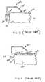
- FIG. 2is a cross-sectional view of a bezel assembly mounted to a display device of the prior art.
- FIG. 3is a cross-sectional view of a bezel assembly mounted to a housing for a display screen of the prior art.
- FIG. 4is a cross-sectional view of a bezel assembly for a touchscreen system mounted to a display device of the prior art.
- FIG. 5is a cross-sectional view of a bezel assembly before installation into a touchscreen system having a curved surface of the prior art.
- FIG. 6is a cross-sectional view of the bezel assembly of FIG. 5 after installation into a touchscreen system.
- FIG. 7is a cross-sectional view of an embodiment of a bezel assembly for a touchscreen system of the present invention, taken prior to assembly of the touchscreen system.
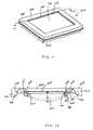
- FIG. 8is an exploded perspective view of a touchscreen system of the present invention, before the bezel assembly has been installed.
- FIG. 9is a cross-sectional view of the bezel assembly for a touchscreen system of the present invention, taken along line 9 - 9 ′ of FIG. 8 .
- FIG. 10is a cross-sectional view of an assembled touchscreen system of the present invention.
- FIG. 11is a perspective view of an assembled touchscreen system of the present invention.
- FIG. 12is a cross-sectional view of an assembled touchscreen system of the present invention, taken along line 12 - 12 ′ in FIG. 11 .
- FIG. 13is a cross-sectional view of an embodiment of a bezel assembly for a touchscreen system of the present invention.
- FIG. 14is an enlarged cross-sectional view of the sealing portion of the bezel assembly shown in FIG. 13 .
- FIG. 15is a cross-sectional view of an alternate embodiment of a bezel assembly for a touchscreen system of the present invention.
- a touchscreen systemis shown in FIG. 1 , which can be applicable to any type of touchscreen technology, e.g., acoustic, resistive, capacitive or infrared.
- a touchscreen system 100includes a touchscreen 111 coupled with a display device (not shown), e.g., a cathode ray tube (CRT) display, liquid crystal display (LCD), plasma display, electroluminescent display, or any suitable display.
- the touchscreen 111includes a touch sensitive region 112 , and touch sensing mechanisms 113 .
- the touch sensing mechanisms 113are located on a periphery of the touchscreen 111 to maximize the touch sensitive region 112 .
- the touchscreen system 100includes control electronics 114 which send and receive information from the touch sensing mechanisms 113 .
- a housing 115is provided for the touchscreen system 100 , the housing including a frame or bezel 116 that covers and protects the touch sensing mechanisms 113 .
- Touchscreen 111can either be an overlay touchscreen, i.e., fabricated on a separate substrate (e.g., a glass substrate) that is mounted over a display panel or it can be a direct-on-tube touchscreen, i.e., fabricated directly onto the face of the display panel such that it is integral with the display (e.g., a CRT panel).
- touchscreen 111has a surface that is suitable for propagating surface acoustic waves, e.g. Rayleigh waves, Love waves, and other acoustic waves sensitive to a touch on a the surface.
- Surface acoustic wave (i.e., SAW) touchscreensare disclosed in U.S. Pat. Nos. 4,644,100, 4,700,176, 5,708,461, 5,854,450, and Re. 33,151, the complete disclosures of which are incorporated herein by reference.
- the touch sensing mechanisms 113include transmitting transducers, receiving transducers and reflective arrays. Touch sensing mechanisms for acoustic touchscreens have been described in detail previously, see for example U.S. Pat. No. 6,411,287, the disclosure of which is incorporated herein by reference.
- the touch sensing mechanisms 113include light emitters and light detectors.
- the light emittersare arranged and the infrared light is steered (e.g., using reflectors) to form an IR grid or pattern across the touch sensitive region 112 .
- Touch sensing mechanisms for infrared touchscreenshave been described in detail previously, see for example U.S. Pat. No. 4,761,637, the disclosure of which is incorporated herein by reference.
- bezel 116that covers the touch sensing mechanisms 113 must be substantially transparent to the wavelength of light being used.
- the touch sensing mechanisms 113include circuitry for measuring resistance, voltage or capacitance at various points around the perimeter of the touch sensitive region 112 .
- FIG. 2is cross-sectional view of a portion of a bezel assembly attached to a display screen (e.g., CRT) 201 as can be used with or without a touchscreen system.
- display screen 201does not include a touchscreen assembly.
- the bezel assemblyis comprised of a resilient member 203 , typically fabricated from molded plastic, that holds a seal 205 against the front surface 206 of CRT screen 201 .
- Seal 205is held against screen 201 by the pressure applied by a cantilever portion 207 of resilient member 203 .
- seal 205may be attached (e.g., bonded), temporarily or permanently, to both resilient member 203 and CRT screen 201 .
- Seal 205prevents contaminants from entering the CRT housing and potentially damaging the internally mounted components, e.g., CRT power supply or, in the case of a touchscreen system, the touchscreen components such as the touch sensing mechanisms 113 or control electronics 114 .
- resilient member 203is attached to display screen 201 by means of corner tabs 209 that are attached to the display via mounting site 211 (e.g., the implosion band for a CRT).
- FIG. 3shows an alternate means of making a seal for a touchscreen system using the bezel.
- a bezel assembly 303 and tab 209are attached to a housing assembly 301 , for example using bolts, locking members, etc.
- FIG. 4is a cross-sectional view of a bezel assembly 401 attached to a display screen 201 , the bezel mounting configuration being similar to that shown in FIG. 2 .
- a touchscreen overlay screen 403is attached via hook and loop material, adhesives, or other means 413 to display screen 201 .
- Touch sensing means 411e.g., acoustic reflective elements and transducers for an acoustic touchscreen
- Seal member 405are located beneath bezel assembly 401 and behind sealing member 405 . Therefore, for acoustic touchscreens, the acoustic absorption of member 405 must be minimized.
- a silicon rubber sealcan provide a robust seal, but may absorb too much acoustic signal to be used with a typical acoustic touchscreen system.
- a lightweight, open cell foam under light compressioncan have minimal impact on the acoustic signal, but may provide limited sealing performance.
- One approach to sealing an acoustic touchscreenis to use a relatively narrow seal, approximately 1 millimeter or less in width. Due to the narrow width of such a seal, a variety of sealing materials can exhibit acceptable levels of acoustic absorption, including those fabricated from solid rubbers. It is well known, however, that a seal is not mechanically stable unless it is wider than it is tall. Thus for a 1 millimeter wide seal, the height must be less than 1 millimeter, and preferably much less than 1 millimeter. As a consequence of these requirements, i.e., a seal less than 1 millimeter in width and a height much less than the width, the design constraints placed upon the bezel assembly and the display housing can be quite demanding.
- tensioning bandscan work well for curved surfaces (e.g., a curved CRT), such seals can fail for flat surfaces (e.g., a LCD) in the regions furthest from the corners where the tensioning bands are anchored.
- flat surfacese.g., a LCD
- small buckling points on the framecan be created, leading to voids in the seal, or manufacturing tolerances can lead to small voids in the seal between the two surfaces.
- Touchscreen system 1787Csold by Elo TouchSystems, Inc., includes a curved bezel assembly for use with a rectangular CRT screen having a curved display surface. This bezel assembly has a rectangular opening corresponding to the CRT screen.
- FIG. 5shows a cross-sectional view of touchscreen system 1787C along one of the sides of the rectangle, before assembly.
- CRT display device 500has curved exterior display surface 501 and bezel assembly 502 has a rigid portion 503 , a flexible portion 504 and a sealing portion 505 .
- Bezel assembly 502has a profile curved in the same direction as the curved surface 501 of CRT 300 , but the radius of curvature for the bezel assembly 502 is slightly larger than that of the display surface 501 of CRT 500 .
- FIG. 6shows a cross-sectional view of touchscreen system 1787C with bezel assembly 502 installed onto CRT 500 and mounted by attaching rigid portions 503 to mounting brackets 506 .
- flexible portion 504When installed, flexible portion 504 is stretched to accommodate the smaller radius of curvature of CRT surface 501 , causing pressure to be exerted on surface 501 via sealing portion 505 .
- Recesses(not shown) can be made in bezel assembly 503 in corner regions to accommodate touch sensing mechanisms, etc.
- the present inventionovercomes the problems associated with the prior sealing systems for flat (i.e. planar) surfaces through the use of a seal coupled to a bezel.
- the bezel's sealing areais pre-stressed so that when the bezel is assembled with a planar touchscreen, uniform pressure is applied between the seal and the touchscreen surface.
- FIG. 7illustrates a cross-sectional view of an embodiment of a frame (i.e., bezel assembly) having a sealing system for use with touchcreen systems of the present invention.
- the bezelis shown before it has been assembled into a touchscreen system.
- Frame 700includes a rigid portion 705 , a flexible portion 706 , a mounting portion 710 and positioning rib 709 .
- Flexible portion 706extends from rigid portion 705 and is directed out of a plane defined by a top surface 714 of rigid portion 706 , toward touchscreen 702 (e.g., flexible portion 706 is angled away from rigid portion 705 ).
- Rigid portion 705can have generally any shape to improve function or appearance of the bezel, e.g., for the embodiment shown in FIG. 7 , rigid portion 705 is approximately parallel to planar touchscreen 702 . Internal (i.e., facing the touchscreen) corner 711 demarcates the transition between rigid portion 705 and flexible portion 706 and there is an internal inflection point 712 between rigid portion 705 and flexible portion 706 . Attached to the end of flexible portion 706 opposed to rigid portion 705 is sealing portion 708 held in place by mounting members 707 , 717 . Preferably mounting member 717 closest to rigid member 705 extends further towards the touchscreen than mounting member 707 . Sealing portion 708 extends beyond both mounting members 707 , 717 .
- the bezel assembly 700can be installed into the touchscreen system by any suitable method, e.g., by attachment to the display device, the touchscreen, or an external housing or mounting bracket.
- the bezel assemblypreferably includes a mounting portion 710 extending in a non-planar direction (e.g., substantially perpendicular) to rigid portion 705 to impart increased stiffness to the outer periphery of bezel assembly 700 .
- the mounting portion 710 of sealing system 700can be attached to display 701 via mounting bracket 704 .
- touchscreen 702is attached to display 701 by attachment member 703 , which may comprise hook and loop material, an adhesive, or the like.
- touchscreen 702can be integral with the display device.
- FIG. 8illustrates an exploded view of an embodiment of a touchscreen system of the present invention.
- Touchscreen system 800is shown prior to assembly and includes a bezel assembly 700 .
- Display 701(which can be any type of display having a flat surface, e.g., LCD, CRT, plasma, electroluminescent, etc.) includes mounting bracket 704 having mounting holes 808 and back housing 809 that can enclose electronics such as control electronics for the touchscreen system.
- Planar touchscreen 702is placed over the front of display 701 .
- Bezel assembly 700is positioned over touchscreen 702 .
- Bezel assembly 700includes a rigid portion 705 and a flexible portion 706 , where dashed line 804 indicates the transition between the rigid and flexible portions.
- Bezel assembly 700also includes sealing portion 708 which will make contact with touchscreen 702 when the touchscreen system is assembled, and mounting portion 710 which can be attach to display 701 via mounting bracket 704 when assembled.
- the bezel assembly 700is pre-stressed such that flexible portion 706 extends toward the central opening and downward from rigid portion 705 toward touchscreen 702 and also has a curved profile along each side of the central opening toward touchscreen 702 , with the center of curvature (i.e., lowest point) along each side indicated by point 803 near a midpoint of each side.
- FIG. 9shows a cross-sectional view of the bezel assembly 700 along line 9 - 9 ′ of FIG. 8 .
- FIG. 10shows a cross-sectional view of bezel assembly 700 including the sealing system of the present invention as it is when installed into a touchscreen system.
- Sealing portion 708 of bezel 700is held in place by mounting members 707 , 717 and is in contact with touchscreen 702 to form a seal therewith.
- Flexible portion 706has been displaced upward, and since it is a pre-stressed resilient member, its displacement results in force exerted onto touchscreen 702 through sealing portion 708 .
- Mounting member 717acts as a hard-stop for flexible portion 706 in the installation of bezel assembly 700 into a touchscreen system. The amount of displacement experienced by flexible portion 706 will depend on several variables, such as materials used, size of touchscreen, and type of touchscreen technology. For the embodiment shown in FIG.
- the displacement of flexible portion 706is such that it is approximately parallel with touchscreen 702 and rigid portion 705 after bezel assembly 700 is installed into touchscreen system 800 .
- mounting portion 710 of bezel 700can be attached to mounting bracket 704 of display 701 by any suitable mechanism, e.g., bolts, threaded screws, clamps, adhesives, snaps, or the like.
- Positioning ribs 709function to position touchscreen 702 , and in the embodiment shown in FIG. 10 , they abut touchscreen 702 .
- FIG. 11illustrates a touchscreen system 800 as assembled.
- FIG. 12illustrates a cross-sectional view along line 12 - 12 ′ of the assembled touchscreen system 800 shown in FIG. 11 (display device 701 , mounting brackets 704 and housing 809 have been excluded from FIG. 12 for purposes of clarity).
- the flexible portion 706 ′, mounting members 707 ′, 717 ′, and sealing portion 708 ′are shown in dashed lines as they were prior to assembly (see FIG. 9 ).
- the displacement of flexible portion 706 upon assembly(indicated by bars 1201 , 1202 , 1203 ) provides tension on touchscreen 702 through sealing member 708 to complete the seal.
- the tension of flexible portion 706 along the length of each side of the bezelprovides an effective seal around the entire perimeter of the bezel.
- the curvature of flexible portion 706 along each sideresults in varying displacement of the flexible portion 706 along each side as it is assembled, with the maximum displacement occurring near the center of curvature (i.e., the center of the sides as indicated by bar 1202 ) and the displacement decreasing monotonically away from the center of the sides towards the corners (indicated by bars 1201 and 1203 ). Therefore, the tension on sealing member 708 increases monotonically toward the center of the sides and is therefore automatically compensated for increased distance away from the corners, resulting in an environmental seal for planar surfaces with substantially uniform tension around the perimeter of the seal, even at the centermost portions of the sides.
- FIG. 13illustrates a cross-sectional view of an embodiment of bezel assembly 700 before installation into a touchscreen system.
- Inner mounting member 717 that extends beyond mounting member 707will function as a hard-stop for flexible portion 706 after it is assembled onto a flat touchscreen surface.
- Preferably inner mounting member 717is rounded where it will come into contact with the touchscreen surface.
- FIG. 14illustrates a cross sectional view of an embodiment of sealing portion 708 before installation into a touchscreen system.
- edge 730 that will face away from the touchscreenhas a narrower cross-sectional dimension than edge 731 that will face the touchscreen.
- finger 732extends from edge 731 , and finger 732 will make initial contact with the touchscreen upon installation.
- Sealing portion 708also preferably includes inner hollow region 733 , which can have any suitable cross-sectional shape, e.g., circular.
- FIG. 15illustrates an alternate embodiment of a bezel assembly 1500 that can be used with the present invention.
- rigid portion 1505includes mounting portions 1510 distributed along its width.
- Rigid portion 1505is not generally parallel to the planar surface of touchscreen 702 , but flexible portion 1506 is directed out of a plane defined by a top surface 1514 of rigid portion 1505 toward touchscreen 702 .
- Flexible portion 1506is tapered as it extends towards touchscreen 702 .
- Adjacent to the internal side of flexible portion 1506is sealing portion 1508 that has downward-pointing tip 1532 . Sealing portion 1508 can be co-molded with rigid portion 1505 and flexible portion 1506 .
- the bezel assembly(e.g., bezel assembly 700 or 1500 ) is preferably formed by shaping plastic, e.g., by molding from a plastic, extruding a plastic material, thermo-forming a plastic, machining, solution-casting, or any other suitable means.
- the plasticcan be a thermoplastic, thermoset, or any other suitable plastic.
- the plasticshould be flexible, yet resilient, so that it can exert pressure on the touchscreen to form the seal.
- an ABS (Acryonitrile Butadiene Styrene)/polycarbonate blendcan be molded to make bezel assemblies of the present invention.
- a plastic that is substantially transparent to the infrared light being used (i.e., light that is transmitted across the screen and detected) in the touch sensormust be chosen, e.g., a polyurethane.
- all sections of bezel assembly excluding sealing portione.g., for the embodiment shown in FIGS. 7-13 , the mounting portion 710 , rib 709 , rigid portion 705 , flexible portion 706 , and mounting members 707 , 717 , and for the embodiment shown in FIG. 15 , rigid portion 1505 , flexible portion 1506 , mounting portions 1510
- sealing portione.g., for the embodiment shown in FIGS. 7-13 , the mounting portion 710 , rib 709 , rigid portion 705 , flexible portion 706 , and mounting members 707 , 717 , and for the embodiment shown in FIG. 15 , rigid portion 1505 , flexible portion 1506 , mounting portions 1510
- sealing portione.g., for the embodiment shown in FIGS. 7-13 , the
- the sealing portion(e.g, 708 , 1508 ) can be made from any suitable sealing material, e.g., a soft thermoplastic or rubber, such as TPU (thermoplastic urethane).
- the sealing portioncan be simultaneously shaped (e.g., co-molded) with the rest of the bezel assembly. Alternatively, the sealing portion can be applied following forming of the rest of the bezel, e.g., by inserting into mounting members 707 , 717 .
- FIGS. 7-15illustrate bezel assemblies having rectangular shapes and openings
- the present inventioncan be equally well used for bezel assemblies having non-rectangular shapes or openings, e.g., circular, oval, hexagonal, diamond-shaped, or any other desired shape.
- the relative size of rigid portion 705 , 1505 to that of flexible portion 706 , 1506will depend on the size the touchscreen, the material used for the bezel, and the type of touchscreen used. For example, in some embodiments it is desired that flexible portion 706 , 1506 having a width (the flexible portion's width being the dimension extending from the rigid portion to the inner periphery of the frame) at least equal to the width of rigid portion 705 , 1505 (the rigid portion's width being the dimension extending from the outer periphery of the frame to the beginning of the flexible portion). In other embodiments, it is preferred that the width of the flexible portion be at least 50% greater than the width of the rigid portion.
- the inventionis illustrated by the following two examples that show particular materials and dimensions for a bezel assembly to be used with a touchscreen system of the present invention. The practice of this invention can be further understood by reference to the following examples, which are provided by way of illustration and not of limitation.
- a bezel assembly for use with the present inventionis provided for a flat 12′′ display having a standard 3-4 width-length aspect ratio for a touchscreen system by molding using a standard ABS or ABS/polycarbonate blend, preferably flame retardant, (e.g., ABS FR AF-312T available from LG Chemical, or PC/ABS alloy GN-5008, available from LG Chemical, or PC+ABS FR 2000, available from Bayer), using the manufacturer's standard instructions for molding conditions.
- the cross-section of the bezel assemblyis shown in FIG. 15 .
- the flexible portionis approximately 1.9 mm thick where it meets the rigid portion, is tapered to about 1 mm thick at its innermost edge, and extends about 10.7 mm from rigid portion to its innermost edge.
- the rigid portioncan be any dimension suitable for the desired touchscreen appearance, weight, etc.
- the rigid portionhas mounting members as shown in FIG. 15 as elements 1510 , as they impart more rigidity to the periphery of the bezel assembly and enable mounting to the display.
- the bezel assemblyis pre-stressed during molding so that the flexible portion is curved toward the planar touchscreen along the length of the sides as illustrated in FIGS. 8 and 9 .
- the sealing portionhas thickness of about 0.9 mm, is made from TPU (thermoplastic urethane) and is co-molded with the rest of the bezel assembly.
- the sealing portionhas a tip extending approximately 0.5 mm toward the touchscreen (shown as element 1532 in FIG. 15 ).
- the curvature of the flexible portionis formed such that when the bezel assembly is installed against a flat 12′′ flat display, the flexible portion is displaced approximately 0.4 mm at the corners (corresponding to bars 1201 and 1203 in FIG. 12 ), and about 1.0 mm at the center of all four sides (corresponding to bar 1202 in FIG. 12 ).
- a bezel assembly for a flat 19′′ display to be used with a touchscreen system of the present inventionis provided.
- Cross-sectional views of the bezel assemblyare shown in FIGS. 7-13 .
- the bezelis formed by molding using a standard ABS or ABS/polycarbonate blend, preferably flame retardant (e.g., ABS FR AF-312T available from LG Chemical, or PC/ABS alloy GN-5008, available from LG Chemical, or PC+ABS FR 2000, available from Bayer), using the manufacturer's standard instructions for molding conditions.
- the flexible portionis approximately 1.5 mm thick and 21 mm long (extending from the rigid portion to the end of mounting member 507 as shown in FIG. 13 ), and the rigid portion can be any dimension suitable for the desired touchscreen appearance, weight, etc.
- the rigid portionhas mounting members 710 as shown in FIGS. 7-13 , as it imparts more rigidity to the periphery of the bezel assembly and enables mounting the bezel to the display.
- the bezel assemblyis pre-stressed during molding so that the flexible portion is curved toward the touchscreen along the length of the sides (see FIGS. 8 and 9 ).
- Mounting members 707 , 717are spaced apart by about 1.3 mm
- the sealing portionhas a cross-section as illustrated in FIG. 14 , with cross-sectional widths at the top of about 1.3 mm and at the base of about 1.8 mm.
- the interior holehas a diameter of about 0.6 mm.
- the sealing portionhas a finger section extending from the main body by about 0.5 mm.
- the sealing portionis extruded as a strip and is made from silicone rubber, e.g., Compound S7309-80, available from Hannifin Corp.
- the curvature of the flexible portionis formed such that when the bezel is installed against a flat 19′′ flat display, the flexible portion is displaced approximately 0.4 mm at the corners (corresponding to bars 1201 and 1203 in FIG. 12 ), and about 1.5 mm at the center of all four sides (corresponding to bar 1202 in FIG. 12 ).
Landscapes
- Engineering & Computer Science (AREA)
- General Engineering & Computer Science (AREA)
- Theoretical Computer Science (AREA)
- Physics & Mathematics (AREA)
- Human Computer Interaction (AREA)
- General Physics & Mathematics (AREA)
- Acoustics & Sound (AREA)
- Devices For Indicating Variable Information By Combining Individual Elements (AREA)
- Position Input By Displaying (AREA)
- Liquid Crystal (AREA)
- Switch Cases, Indication, And Locking (AREA)
Abstract
Description
Claims (31)
Priority Applications (6)
| Application Number | Priority Date | Filing Date | Title |
|---|---|---|---|
| US10/870,837US7315336B2 (en) | 2004-06-16 | 2004-06-16 | Stress seal for touchscreen systems |
| TW094119245ATWI380195B (en) | 2004-06-16 | 2005-06-10 | Touchscreen systems and method for assembling the same |
| JP2007516727AJP4833201B2 (en) | 2004-06-16 | 2005-06-14 | Stress sealing for touch screen systems |
| EP11154956AEP2317418A1 (en) | 2004-06-16 | 2005-06-14 | Stress seal for touchscreen systems |
| PCT/US2005/021269WO2006007390A2 (en) | 2004-06-16 | 2005-06-14 | Stress seal for touchscreen systems |
| EP05760963AEP1766503B1 (en) | 2004-06-16 | 2005-06-14 | Stress seal for touchscreen systems |
Applications Claiming Priority (1)
| Application Number | Priority Date | Filing Date | Title |
|---|---|---|---|
| US10/870,837US7315336B2 (en) | 2004-06-16 | 2004-06-16 | Stress seal for touchscreen systems |
Publications (2)
| Publication Number | Publication Date |
|---|---|
| US20050280746A1 US20050280746A1 (en) | 2005-12-22 |
| US7315336B2true US7315336B2 (en) | 2008-01-01 |
Family
ID=34982112
Family Applications (1)
| Application Number | Title | Priority Date | Filing Date |
|---|---|---|---|
| US10/870,837Expired - LifetimeUS7315336B2 (en) | 2004-06-16 | 2004-06-16 | Stress seal for touchscreen systems |
Country Status (5)
| Country | Link |
|---|---|
| US (1) | US7315336B2 (en) |
| EP (2) | EP1766503B1 (en) |
| JP (1) | JP4833201B2 (en) |
| TW (1) | TWI380195B (en) |
| WO (1) | WO2006007390A2 (en) |
Cited By (26)
| Publication number | Priority date | Publication date | Assignee | Title |
|---|---|---|---|---|
| US20090153768A1 (en)* | 2007-12-18 | 2009-06-18 | Yukio Ooami | Flat-panel display device and its manufacturing method |
| US7654754B1 (en)* | 2005-11-07 | 2010-02-02 | Lakey James B | Camera having improved camera cushion and seal |
| US9189109B2 (en) | 2012-07-18 | 2015-11-17 | Sentons Inc. | Detection of type of object used to provide a touch contact input |
| US9348468B2 (en) | 2013-06-07 | 2016-05-24 | Sentons Inc. | Detecting multi-touch inputs |
| US9417754B2 (en) | 2011-08-05 | 2016-08-16 | P4tents1, LLC | User interface system, method, and computer program product |
| US20160249464A1 (en)* | 2015-02-25 | 2016-08-25 | Samsung Display Co., Ltd | Curved display device |
| US9449476B2 (en) | 2011-11-18 | 2016-09-20 | Sentons Inc. | Localized haptic feedback |
| US9459715B1 (en) | 2013-09-20 | 2016-10-04 | Sentons Inc. | Using spectral control in detecting touch input |
| US9477350B2 (en) | 2011-04-26 | 2016-10-25 | Sentons Inc. | Method and apparatus for active ultrasonic touch devices |
| US9513727B2 (en) | 2012-07-18 | 2016-12-06 | Sentons Inc. | Touch input surface microphone |
| US9524063B2 (en) | 2012-07-18 | 2016-12-20 | Sentons Inc. | Detection of a number of touch contacts of a multi-touch input |
| US9588552B2 (en) | 2013-09-11 | 2017-03-07 | Sentons Inc. | Attaching electrical components using non-conductive adhesive |
| US9594450B2 (en) | 2011-11-18 | 2017-03-14 | Sentons Inc. | Controlling audio volume using touch input force |
| US9639213B2 (en) | 2011-04-26 | 2017-05-02 | Sentons Inc. | Using multiple signals to detect touch input |
| US9880671B2 (en) | 2013-10-08 | 2018-01-30 | Sentons Inc. | Damping vibrational wave reflections |
| US10048811B2 (en) | 2015-09-18 | 2018-08-14 | Sentons Inc. | Detecting touch input provided by signal transmitting stylus |
| US10126877B1 (en) | 2017-02-01 | 2018-11-13 | Sentons Inc. | Update of reference data for touch input detection |
| US10198097B2 (en) | 2011-04-26 | 2019-02-05 | Sentons Inc. | Detecting touch input force |
| US10235004B1 (en) | 2011-11-18 | 2019-03-19 | Sentons Inc. | Touch input detector with an integrated antenna |
| US10296144B2 (en) | 2016-12-12 | 2019-05-21 | Sentons Inc. | Touch input detection with shared receivers |
| US10481645B2 (en) | 2015-09-11 | 2019-11-19 | Lucan Patent Holdco, LLC | Secondary gesture input mechanism for touchscreen devices |
| US10585522B2 (en) | 2017-02-27 | 2020-03-10 | Sentons Inc. | Detection of non-touch inputs using a signature |
| US10908741B2 (en) | 2016-11-10 | 2021-02-02 | Sentons Inc. | Touch input detection along device sidewall |
| US11009411B2 (en) | 2017-08-14 | 2021-05-18 | Sentons Inc. | Increasing sensitivity of a sensor using an encoded signal |
| US11327599B2 (en) | 2011-04-26 | 2022-05-10 | Sentons Inc. | Identifying a contact type |
| US11580829B2 (en) | 2017-08-14 | 2023-02-14 | Sentons Inc. | Dynamic feedback for haptics |
Families Citing this family (13)
| Publication number | Priority date | Publication date | Assignee | Title |
|---|---|---|---|---|
| US20070221034A1 (en)* | 2006-03-02 | 2007-09-27 | Tom Pigoski | Method and apparatus for converting a CD-jukebox to digital jukebox |
| US9213929B2 (en)* | 2006-05-30 | 2015-12-15 | Dai Nippon Printing Co., Ltd. | Pattern printed sheet |
| WO2010021188A1 (en)* | 2008-08-22 | 2010-02-25 | シャープ株式会社 | Display device and television receiver |
| DE102009003990A1 (en)* | 2009-01-07 | 2010-07-08 | Wincor Nixdorf International Gmbh | Touch-sensitive input device |
| US8310458B2 (en)* | 2009-07-06 | 2012-11-13 | Research In Motion Limited | Electronic device including a moveable touch-sensitive input and method of controlling same |
| US9081428B2 (en)* | 2010-04-23 | 2015-07-14 | Psion Inc. | Apparatus and method for impact resistant touchscreen display module |
| US20130335211A1 (en)* | 2011-02-24 | 2013-12-19 | Kyocera Corporation | Electronic device |
| WO2012137440A1 (en)* | 2011-04-01 | 2012-10-11 | 京セラ株式会社 | Electronic device |
| TWI467458B (en)* | 2012-09-21 | 2015-01-01 | Touchplus Information Corp | Capacitive touch apparatus |
| DE102012224352A1 (en)* | 2012-12-21 | 2014-06-26 | Continental Automotive Gmbh | Electro-optical display with a transparent cover |
| JP2015225570A (en)* | 2014-05-29 | 2015-12-14 | 富士通テン株式会社 | Operating device |
| CN105158988B (en) | 2015-09-30 | 2019-05-07 | 京东方科技集团股份有限公司 | A plastic frame, a backlight module and a display device |
| CN118312056B (en)* | 2024-04-03 | 2024-10-08 | 东莞市友联亨达光电有限公司 | Resistive touch screen with shielding layer and shielding method thereof |
Citations (28)
| Publication number | Priority date | Publication date | Assignee | Title |
|---|---|---|---|---|
| EP0087024A2 (en) | 1982-02-20 | 1983-08-31 | Athena Reproductions Limited | Improvements in or relating to frames |
| US4642423A (en) | 1985-08-30 | 1987-02-10 | Zenith Electronics Corporation | Touch control system for use with or having a three-dimensionally curved touch surface |
| US4644100A (en) | 1985-03-22 | 1987-02-17 | Zenith Electronics Corporation | Surface acoustic wave touch panel system |
| US4645870A (en) | 1985-10-15 | 1987-02-24 | Zenith Electronics Corporation | Touch control system for use with a display panel or other touch controlled device |
| US4700176A (en) | 1985-02-05 | 1987-10-13 | Zenith Electronis Corporation | Tough control arrangement for graphics display apparatus |
| US4746914A (en) | 1985-02-05 | 1988-05-24 | Zenith Electronics Corporation | Cathode ray tube for use in a touch panel display system |
| US4761637A (en) | 1984-06-18 | 1988-08-02 | Carroll Touch Inc. | Touch input device |
| US4791416A (en) | 1985-02-05 | 1988-12-13 | Zenith Electronics Corporation | Touch control system for controllable apparatus |
| US4825212A (en) | 1986-11-14 | 1989-04-25 | Zenith Electronics Corporation | Arrangement for use with a touch control system having a spherically curved touch surface |
| US4880665A (en) | 1987-01-20 | 1989-11-14 | Zenith Electronics Corporation | Touch control arrangement for graphics display apparatus having saw reflectors of frit composition |
| USRE33151E (en) | 1985-02-05 | 1990-01-23 | Zenith Electronics Corporation | Touch control system for controllable apparatus |
| US5072427A (en) | 1990-11-16 | 1991-12-10 | Exzec Inc. | Acoustic touch position sensor with shear to lamb wave conversion |
| US5162618A (en) | 1990-11-16 | 1992-11-10 | Exzec, Inc. | Acoustic touch position sensor with first order lamb wave reflective arrays |
| US5177327A (en) | 1990-11-16 | 1993-01-05 | Exzec, Inc. | Acoustic touch position sensor using shear wave propagation |
| US5243148A (en) | 1990-11-16 | 1993-09-07 | Exzec, Inc. | Touch panel for an acoustic touch position sensor using shear wave propagation |
| US5260521A (en) | 1990-11-16 | 1993-11-09 | Exzec, Inc. | Acoustic touch position sensor using shear wave propagation |
| US5329070A (en) | 1990-11-16 | 1994-07-12 | Carroll Touch Inc. | Touch panel for an acoustic touch position sensor |
| US5332238A (en)* | 1991-07-30 | 1994-07-26 | Restaurant Technology, Inc. | Surface acoustic wave touchscreen sealing system |
| US5573077A (en) | 1990-11-16 | 1996-11-12 | Knowles; Terence J. | Acoustic touch position sensor |
| US5591945A (en) | 1995-04-19 | 1997-01-07 | Elo Touchsystems, Inc. | Acoustic touch position sensor using higher order horizontally polarized shear wave propagation |
| US5708461A (en) | 1995-01-24 | 1998-01-13 | Elo Touchsystems, Inc. | Acoustic touch position sensor using a low-loss transparent substrate |
| US5739479A (en) | 1996-03-04 | 1998-04-14 | Elo Touchsystems, Inc. | Gentle-bevel flat acoustic wave touch sensor |
| US5784054A (en)* | 1996-03-22 | 1998-07-21 | Elo Toughsystems, Inc. | Surface acoustic wave touchscreen with housing seal |
| US6254105B1 (en) | 1999-04-02 | 2001-07-03 | Elo Touchsystems, Inc. | Sealing system for acoustic wave touchscreens |
| US6411287B1 (en) | 1999-09-08 | 2002-06-25 | Elo Touchsystems, Inc. | Stress seal for acoustic wave touchscreens |
| US20020149571A1 (en)* | 2001-04-13 | 2002-10-17 | Roberts Jerry B. | Method and apparatus for force-based touch input |
| US20030006971A1 (en)* | 1999-07-31 | 2003-01-09 | Blanchard Randall D. | Touch panel with improved optical performance |
| US6677934B1 (en)* | 1999-07-30 | 2004-01-13 | L-3 Communications | Infrared touch panel with improved sunlight rejection |
Family Cites Families (2)
| Publication number | Priority date | Publication date | Assignee | Title |
|---|---|---|---|---|
| JPH11353116A (en)* | 1998-06-10 | 1999-12-24 | Komatsu Ltd | Touch panel seal structure |
| US6897852B2 (en)* | 2002-03-28 | 2005-05-24 | Symbol Technologies, Inc. | Information input display device |
- 2004
- 2004-06-16USUS10/870,837patent/US7315336B2/ennot_activeExpired - Lifetime
- 2005
- 2005-06-10TWTW094119245Apatent/TWI380195B/ennot_activeIP Right Cessation
- 2005-06-14WOPCT/US2005/021269patent/WO2006007390A2/enactiveApplication Filing
- 2005-06-14EPEP05760963Apatent/EP1766503B1/ennot_activeExpired - Lifetime
- 2005-06-14EPEP11154956Apatent/EP2317418A1/ennot_activeWithdrawn
- 2005-06-14JPJP2007516727Apatent/JP4833201B2/ennot_activeExpired - Fee Related
Patent Citations (30)
| Publication number | Priority date | Publication date | Assignee | Title |
|---|---|---|---|---|
| EP0087024A2 (en) | 1982-02-20 | 1983-08-31 | Athena Reproductions Limited | Improvements in or relating to frames |
| US4761637A (en) | 1984-06-18 | 1988-08-02 | Carroll Touch Inc. | Touch input device |
| US4700176A (en) | 1985-02-05 | 1987-10-13 | Zenith Electronis Corporation | Tough control arrangement for graphics display apparatus |
| US4746914A (en) | 1985-02-05 | 1988-05-24 | Zenith Electronics Corporation | Cathode ray tube for use in a touch panel display system |
| US4791416A (en) | 1985-02-05 | 1988-12-13 | Zenith Electronics Corporation | Touch control system for controllable apparatus |
| US4859996A (en) | 1985-02-05 | 1989-08-22 | Zenith Electronics Corporation | Touch control arrangement for graphics display apparatus |
| USRE33151E (en) | 1985-02-05 | 1990-01-23 | Zenith Electronics Corporation | Touch control system for controllable apparatus |
| US4644100A (en) | 1985-03-22 | 1987-02-17 | Zenith Electronics Corporation | Surface acoustic wave touch panel system |
| US4642423A (en) | 1985-08-30 | 1987-02-10 | Zenith Electronics Corporation | Touch control system for use with or having a three-dimensionally curved touch surface |
| US4645870A (en) | 1985-10-15 | 1987-02-24 | Zenith Electronics Corporation | Touch control system for use with a display panel or other touch controlled device |
| US4825212A (en) | 1986-11-14 | 1989-04-25 | Zenith Electronics Corporation | Arrangement for use with a touch control system having a spherically curved touch surface |
| US4880665A (en) | 1987-01-20 | 1989-11-14 | Zenith Electronics Corporation | Touch control arrangement for graphics display apparatus having saw reflectors of frit composition |
| US5177327A (en) | 1990-11-16 | 1993-01-05 | Exzec, Inc. | Acoustic touch position sensor using shear wave propagation |
| US5162618A (en) | 1990-11-16 | 1992-11-10 | Exzec, Inc. | Acoustic touch position sensor with first order lamb wave reflective arrays |
| US5072427A (en) | 1990-11-16 | 1991-12-10 | Exzec Inc. | Acoustic touch position sensor with shear to lamb wave conversion |
| US5243148A (en) | 1990-11-16 | 1993-09-07 | Exzec, Inc. | Touch panel for an acoustic touch position sensor using shear wave propagation |
| US5260521A (en) | 1990-11-16 | 1993-11-09 | Exzec, Inc. | Acoustic touch position sensor using shear wave propagation |
| US5329070A (en) | 1990-11-16 | 1994-07-12 | Carroll Touch Inc. | Touch panel for an acoustic touch position sensor |
| US5573077A (en) | 1990-11-16 | 1996-11-12 | Knowles; Terence J. | Acoustic touch position sensor |
| US5332238A (en)* | 1991-07-30 | 1994-07-26 | Restaurant Technology, Inc. | Surface acoustic wave touchscreen sealing system |
| US5708461A (en) | 1995-01-24 | 1998-01-13 | Elo Touchsystems, Inc. | Acoustic touch position sensor using a low-loss transparent substrate |
| US5591945A (en) | 1995-04-19 | 1997-01-07 | Elo Touchsystems, Inc. | Acoustic touch position sensor using higher order horizontally polarized shear wave propagation |
| US5854450A (en) | 1995-04-19 | 1998-12-29 | Elo Touchsystems, Inc. | Acoustic condition sensor employing a plurality of mutually non-orthogonal waves |
| US5739479A (en) | 1996-03-04 | 1998-04-14 | Elo Touchsystems, Inc. | Gentle-bevel flat acoustic wave touch sensor |
| US5784054A (en)* | 1996-03-22 | 1998-07-21 | Elo Toughsystems, Inc. | Surface acoustic wave touchscreen with housing seal |
| US6254105B1 (en) | 1999-04-02 | 2001-07-03 | Elo Touchsystems, Inc. | Sealing system for acoustic wave touchscreens |
| US6677934B1 (en)* | 1999-07-30 | 2004-01-13 | L-3 Communications | Infrared touch panel with improved sunlight rejection |
| US20030006971A1 (en)* | 1999-07-31 | 2003-01-09 | Blanchard Randall D. | Touch panel with improved optical performance |
| US6411287B1 (en) | 1999-09-08 | 2002-06-25 | Elo Touchsystems, Inc. | Stress seal for acoustic wave touchscreens |
| US20020149571A1 (en)* | 2001-04-13 | 2002-10-17 | Roberts Jerry B. | Method and apparatus for force-based touch input |
Non-Patent Citations (1)
| Title |
|---|
| Search Report for International Application No. PCT/US2005/021269, mailed Jan. 1, 2006. |
Cited By (107)
| Publication number | Priority date | Publication date | Assignee | Title |
|---|---|---|---|---|
| US7654754B1 (en)* | 2005-11-07 | 2010-02-02 | Lakey James B | Camera having improved camera cushion and seal |
| US7872704B2 (en)* | 2007-12-18 | 2011-01-18 | Toshiba Matsushita Display Technology Co., Ltd. | Flat-panel display device and its manufacturing method |
| US20090153768A1 (en)* | 2007-12-18 | 2009-06-18 | Yukio Ooami | Flat-panel display device and its manufacturing method |
| US9639213B2 (en) | 2011-04-26 | 2017-05-02 | Sentons Inc. | Using multiple signals to detect touch input |
| US12299226B2 (en) | 2011-04-26 | 2025-05-13 | Sentons Inc. | Identifying signal disturbance |
| US11907464B2 (en) | 2011-04-26 | 2024-02-20 | Sentons Inc. | Identifying a contact type |
| US11327599B2 (en) | 2011-04-26 | 2022-05-10 | Sentons Inc. | Identifying a contact type |
| US10969908B2 (en) | 2011-04-26 | 2021-04-06 | Sentons Inc. | Using multiple signals to detect touch input |
| US10877581B2 (en) | 2011-04-26 | 2020-12-29 | Sentons Inc. | Detecting touch input force |
| US10444909B2 (en) | 2011-04-26 | 2019-10-15 | Sentons Inc. | Using multiple signals to detect touch input |
| US9477350B2 (en) | 2011-04-26 | 2016-10-25 | Sentons Inc. | Method and apparatus for active ultrasonic touch devices |
| US10198097B2 (en) | 2011-04-26 | 2019-02-05 | Sentons Inc. | Detecting touch input force |
| US10386960B1 (en) | 2011-08-05 | 2019-08-20 | P4tents1, LLC | Devices, methods, and graphical user interfaces for manipulating user interface objects with visual and/or haptic feedback |
| US10222891B1 (en) | 2011-08-05 | 2019-03-05 | P4tents1, LLC | Setting interface system, method, and computer program product for a multi-pressure selection touch screen |
| US11740727B1 (en) | 2011-08-05 | 2023-08-29 | P4Tents1 Llc | Devices, methods, and graphical user interfaces for manipulating user interface objects with visual and/or haptic feedback |
| US9417754B2 (en) | 2011-08-05 | 2016-08-16 | P4tents1, LLC | User interface system, method, and computer program product |
| US11061503B1 (en) | 2011-08-05 | 2021-07-13 | P4tents1, LLC | Devices, methods, and graphical user interfaces for manipulating user interface objects with visual and/or haptic feedback |
| US10996787B1 (en) | 2011-08-05 | 2021-05-04 | P4tents1, LLC | Gesture-equipped touch screen system, method, and computer program product |
| US10013095B1 (en) | 2011-08-05 | 2018-07-03 | P4tents1, LLC | Multi-type gesture-equipped touch screen system, method, and computer program product |
| US10013094B1 (en) | 2011-08-05 | 2018-07-03 | P4tents1, LLC | System, method, and computer program product for a multi-pressure selection touch screen |
| US10031607B1 (en) | 2011-08-05 | 2018-07-24 | P4tents1, LLC | System, method, and computer program product for a multi-pressure selection touch screen |
| US10936114B1 (en) | 2011-08-05 | 2021-03-02 | P4tents1, LLC | Gesture-equipped touch screen system, method, and computer program product |
| US10838542B1 (en) | 2011-08-05 | 2020-11-17 | P4tents1, LLC | Gesture-equipped touch screen system, method, and computer program product |
| US10120480B1 (en) | 2011-08-05 | 2018-11-06 | P4tents1, LLC | Application-specific pressure-sensitive touch screen system, method, and computer program product |
| US10788931B1 (en) | 2011-08-05 | 2020-09-29 | P4tents1, LLC | Devices, methods, and graphical user interfaces for manipulating user interface objects with visual and/or haptic feedback |
| US10133397B1 (en) | 2011-08-05 | 2018-11-20 | P4tents1, LLC | Tri-state gesture-equipped touch screen system, method, and computer program product |
| US10146353B1 (en) | 2011-08-05 | 2018-12-04 | P4tents1, LLC | Touch screen system, method, and computer program product |
| US10156921B1 (en) | 2011-08-05 | 2018-12-18 | P4tents1, LLC | Tri-state gesture-equipped touch screen system, method, and computer program product |
| US10162448B1 (en) | 2011-08-05 | 2018-12-25 | P4tents1, LLC | System, method, and computer program product for a pressure-sensitive touch screen for messages |
| US10782819B1 (en) | 2011-08-05 | 2020-09-22 | P4tents1, LLC | Gesture-equipped touch screen system, method, and computer program product |
| US10725581B1 (en) | 2011-08-05 | 2020-07-28 | P4tents1, LLC | Devices, methods and graphical user interfaces for manipulating user interface objects with visual and/or haptic feedback |
| US10203794B1 (en) | 2011-08-05 | 2019-02-12 | P4tents1, LLC | Pressure-sensitive home interface system, method, and computer program product |
| US10540039B1 (en) | 2011-08-05 | 2020-01-21 | P4tents1, LLC | Devices and methods for navigating between user interface |
| US10209808B1 (en) | 2011-08-05 | 2019-02-19 | P4tents1, LLC | Pressure-based interface system, method, and computer program product with virtual display layers |
| US10209809B1 (en) | 2011-08-05 | 2019-02-19 | P4tents1, LLC | Pressure-sensitive touch screen system, method, and computer program product for objects |
| US10209806B1 (en) | 2011-08-05 | 2019-02-19 | P4tents1, LLC | Tri-state gesture-equipped touch screen system, method, and computer program product |
| US10209807B1 (en) | 2011-08-05 | 2019-02-19 | P4tents1, LLC | Pressure sensitive touch screen system, method, and computer program product for hyperlinks |
| US10222892B1 (en) | 2011-08-05 | 2019-03-05 | P4tents1, LLC | System, method, and computer program product for a multi-pressure selection touch screen |
| US10222895B1 (en) | 2011-08-05 | 2019-03-05 | P4tents1, LLC | Pressure-based touch screen system, method, and computer program product with virtual display layers |
| US10649579B1 (en) | 2011-08-05 | 2020-05-12 | P4tents1, LLC | Devices, methods, and graphical user interfaces for manipulating user interface objects with visual and/or haptic feedback |
| US10222893B1 (en) | 2011-08-05 | 2019-03-05 | P4tents1, LLC | Pressure-based touch screen system, method, and computer program product with virtual display layers |
| US10222894B1 (en) | 2011-08-05 | 2019-03-05 | P4tents1, LLC | System, method, and computer program product for a multi-pressure selection touch screen |
| US10671213B1 (en) | 2011-08-05 | 2020-06-02 | P4tents1, LLC | Devices, methods, and graphical user interfaces for manipulating user interface objects with visual and/or haptic feedback |
| US10671212B1 (en) | 2011-08-05 | 2020-06-02 | P4tents1, LLC | Gesture-equipped touch screen system, method, and computer program product |
| US10275087B1 (en) | 2011-08-05 | 2019-04-30 | P4tents1, LLC | Devices, methods, and graphical user interfaces for manipulating user interface objects with visual and/or haptic feedback |
| US10275086B1 (en) | 2011-08-05 | 2019-04-30 | P4tents1, LLC | Gesture-equipped touch screen system, method, and computer program product |
| US10664097B1 (en) | 2011-08-05 | 2020-05-26 | P4tents1, LLC | Devices, methods, and graphical user interfaces for manipulating user interface objects with visual and/or haptic feedback |
| US10338736B1 (en) | 2011-08-05 | 2019-07-02 | P4tents1, LLC | Devices, methods, and graphical user interfaces for manipulating user interface objects with visual and/or haptic feedback |
| US10345961B1 (en) | 2011-08-05 | 2019-07-09 | P4tents1, LLC | Devices and methods for navigating between user interfaces |
| US10656755B1 (en) | 2011-08-05 | 2020-05-19 | P4tents1, LLC | Gesture-equipped touch screen system, method, and computer program product |
| US10365758B1 (en) | 2011-08-05 | 2019-07-30 | P4tents1, LLC | Devices, methods, and graphical user interfaces for manipulating user interface objects with visual and/or haptic feedback |
| US10656756B1 (en) | 2011-08-05 | 2020-05-19 | P4tents1, LLC | Gesture-equipped touch screen system, method, and computer program product |
| US10656758B1 (en) | 2011-08-05 | 2020-05-19 | P4tents1, LLC | Gesture-equipped touch screen system, method, and computer program product |
| US10656757B1 (en) | 2011-08-05 | 2020-05-19 | P4tents1, LLC | Gesture-equipped touch screen system, method, and computer program product |
| US10656759B1 (en) | 2011-08-05 | 2020-05-19 | P4tents1, LLC | Devices, methods, and graphical user interfaces for manipulating user interface objects with visual and/or haptic feedback |
| US10656753B1 (en) | 2011-08-05 | 2020-05-19 | P4tents1, LLC | Gesture-equipped touch screen system, method, and computer program product |
| US10656752B1 (en) | 2011-08-05 | 2020-05-19 | P4tents1, LLC | Gesture-equipped touch screen system, method, and computer program product |
| US10521047B1 (en) | 2011-08-05 | 2019-12-31 | P4tents1, LLC | Gesture-equipped touch screen system, method, and computer program product |
| US10534474B1 (en) | 2011-08-05 | 2020-01-14 | P4tents1, LLC | Gesture-equipped touch screen system, method, and computer program product |
| US10551966B1 (en) | 2011-08-05 | 2020-02-04 | P4tents1, LLC | Gesture-equipped touch screen system, method, and computer program product |
| US10656754B1 (en) | 2011-08-05 | 2020-05-19 | P4tents1, LLC | Devices and methods for navigating between user interfaces |
| US10649571B1 (en) | 2011-08-05 | 2020-05-12 | P4tents1, LLC | Devices, methods, and graphical user interfaces for manipulating user interface objects with visual and/or haptic feedback |
| US10592039B1 (en) | 2011-08-05 | 2020-03-17 | P4tents1, LLC | Gesture-equipped touch screen system, method, and computer program product for displaying multiple active applications |
| US10606396B1 (en) | 2011-08-05 | 2020-03-31 | P4tents1, LLC | Gesture-equipped touch screen methods for duration-based functions |
| US10642413B1 (en) | 2011-08-05 | 2020-05-05 | P4tents1, LLC | Gesture-equipped touch screen system, method, and computer program product |
| US10649580B1 (en) | 2011-08-05 | 2020-05-12 | P4tents1, LLC | Devices, methods, and graphical use interfaces for manipulating user interface objects with visual and/or haptic feedback |
| US10649578B1 (en) | 2011-08-05 | 2020-05-12 | P4tents1, LLC | Gesture-equipped touch screen system, method, and computer program product |
| US10649581B1 (en) | 2011-08-05 | 2020-05-12 | P4tents1, LLC | Devices, methods, and graphical user interfaces for manipulating user interface objects with visual and/or haptic feedback |
| US9594450B2 (en) | 2011-11-18 | 2017-03-14 | Sentons Inc. | Controlling audio volume using touch input force |
| US10235004B1 (en) | 2011-11-18 | 2019-03-19 | Sentons Inc. | Touch input detector with an integrated antenna |
| US11829555B2 (en) | 2011-11-18 | 2023-11-28 | Sentons Inc. | Controlling audio volume using touch input force |
| US11209931B2 (en) | 2011-11-18 | 2021-12-28 | Sentons Inc. | Localized haptic feedback |
| US11016607B2 (en) | 2011-11-18 | 2021-05-25 | Sentons Inc. | Controlling audio volume using touch input force |
| US9449476B2 (en) | 2011-11-18 | 2016-09-20 | Sentons Inc. | Localized haptic feedback |
| US10055066B2 (en) | 2011-11-18 | 2018-08-21 | Sentons Inc. | Controlling audio volume using touch input force |
| US10162443B2 (en) | 2011-11-18 | 2018-12-25 | Sentons Inc. | Virtual keyboard interaction using touch input force |
| US10732755B2 (en) | 2011-11-18 | 2020-08-04 | Sentons Inc. | Controlling audio volume using touch input force |
| US10353509B2 (en) | 2011-11-18 | 2019-07-16 | Sentons Inc. | Controlling audio volume using touch input force |
| US10698528B2 (en) | 2011-11-18 | 2020-06-30 | Sentons Inc. | Localized haptic feedback |
| US10248262B2 (en) | 2011-11-18 | 2019-04-02 | Sentons Inc. | User interface interaction using touch input force |
| US9823760B2 (en) | 2012-07-18 | 2017-11-21 | Sentons Inc. | Touch input surface speaker |
| US9524063B2 (en) | 2012-07-18 | 2016-12-20 | Sentons Inc. | Detection of a number of touch contacts of a multi-touch input |
| US9513727B2 (en) | 2012-07-18 | 2016-12-06 | Sentons Inc. | Touch input surface microphone |
| US9189109B2 (en) | 2012-07-18 | 2015-11-17 | Sentons Inc. | Detection of type of object used to provide a touch contact input |
| US10860132B2 (en) | 2012-07-18 | 2020-12-08 | Sentons Inc. | Identifying a contact type |
| US10466836B2 (en) | 2012-07-18 | 2019-11-05 | Sentons Inc. | Using a type of object to provide a touch contact input |
| US10209825B2 (en) | 2012-07-18 | 2019-02-19 | Sentons Inc. | Detection of type of object used to provide a touch contact input |
| US9348468B2 (en) | 2013-06-07 | 2016-05-24 | Sentons Inc. | Detecting multi-touch inputs |
| US9588552B2 (en) | 2013-09-11 | 2017-03-07 | Sentons Inc. | Attaching electrical components using non-conductive adhesive |
| US9459715B1 (en) | 2013-09-20 | 2016-10-04 | Sentons Inc. | Using spectral control in detecting touch input |
| US9880671B2 (en) | 2013-10-08 | 2018-01-30 | Sentons Inc. | Damping vibrational wave reflections |
| US9733502B2 (en)* | 2015-02-25 | 2017-08-15 | Samsung Display Co., Ltd. | Curved display device |
| US20160249464A1 (en)* | 2015-02-25 | 2016-08-25 | Samsung Display Co., Ltd | Curved display device |
| US10481645B2 (en) | 2015-09-11 | 2019-11-19 | Lucan Patent Holdco, LLC | Secondary gesture input mechanism for touchscreen devices |
| US10048811B2 (en) | 2015-09-18 | 2018-08-14 | Sentons Inc. | Detecting touch input provided by signal transmitting stylus |
| US10908741B2 (en) | 2016-11-10 | 2021-02-02 | Sentons Inc. | Touch input detection along device sidewall |
| US10509515B2 (en) | 2016-12-12 | 2019-12-17 | Sentons Inc. | Touch input detection with shared receivers |
| US10296144B2 (en) | 2016-12-12 | 2019-05-21 | Sentons Inc. | Touch input detection with shared receivers |
| US10126877B1 (en) | 2017-02-01 | 2018-11-13 | Sentons Inc. | Update of reference data for touch input detection |
| US10444905B2 (en) | 2017-02-01 | 2019-10-15 | Sentons Inc. | Update of reference data for touch input detection |
| US11061510B2 (en) | 2017-02-27 | 2021-07-13 | Sentons Inc. | Detection of non-touch inputs using a signature |
| US10585522B2 (en) | 2017-02-27 | 2020-03-10 | Sentons Inc. | Detection of non-touch inputs using a signature |
| US11262253B2 (en) | 2017-08-14 | 2022-03-01 | Sentons Inc. | Touch input detection using a piezoresistive sensor |
| US11580829B2 (en) | 2017-08-14 | 2023-02-14 | Sentons Inc. | Dynamic feedback for haptics |
| US11435242B2 (en) | 2017-08-14 | 2022-09-06 | Sentons Inc. | Increasing sensitivity of a sensor using an encoded signal |
| US11340124B2 (en) | 2017-08-14 | 2022-05-24 | Sentons Inc. | Piezoresistive sensor for detecting a physical disturbance |
| US11009411B2 (en) | 2017-08-14 | 2021-05-18 | Sentons Inc. | Increasing sensitivity of a sensor using an encoded signal |
Also Published As
| Publication number | Publication date |
|---|---|
| JP4833201B2 (en) | 2011-12-07 |
| WO2006007390A3 (en) | 2006-03-23 |
| EP2317418A1 (en) | 2011-05-04 |
| JP2008503804A (en) | 2008-02-07 |
| EP1766503B1 (en) | 2011-08-10 |
| TW200602963A (en) | 2006-01-16 |
| US20050280746A1 (en) | 2005-12-22 |
| WO2006007390A2 (en) | 2006-01-19 |
| EP1766503A2 (en) | 2007-03-28 |
| TWI380195B (en) | 2012-12-21 |
Similar Documents
| Publication | Publication Date | Title |
|---|---|---|
| US7315336B2 (en) | Stress seal for touchscreen systems | |
| US6411287B1 (en) | Stress seal for acoustic wave touchscreens | |
| US7499037B2 (en) | Video display and touchscreen assembly, system and method | |
| CN108681131B (en) | Display device | |
| US8576186B2 (en) | Holding structure for a touch panel | |
| US8988364B2 (en) | Display device and input device | |
| US6254105B1 (en) | Sealing system for acoustic wave touchscreens | |
| EP2325731B1 (en) | Holding structure for a touch panel | |
| EP1884870B1 (en) | Portable terminal | |
| WO2012114761A1 (en) | Electronic device | |
| JP4911647B2 (en) | Touch panel holding structure | |
| EP2325733A1 (en) | Holding structure for a touch panel | |
| JP2006514367A (en) | Touch sensor with sealing force | |
| AU2004286548A1 (en) | Tactile touch-sensing system | |
| KR20200129716A (en) | Panel assembling frame for display device with infrared touch sensor | |
| US9176585B2 (en) | Touch panel support | |
| US7110247B2 (en) | Touch panel holder frame, spacer member, and display device | |
| TW202141228A (en) | Sensor unit and structure for attaching sensor unit | |
| JP4299737B2 (en) | Display device and electronic apparatus using the display device | |
| JP5459076B2 (en) | Display device | |
| JP2012203546A (en) | Electronic apparatus | |
| KR20180087930A (en) | Display device | |
| CN220154762U (en) | Filter strips and electronic equipment | |
| JPH01152529A (en) | Dust guard for optical touch screen | |
| KR20250043723A (en) | Optical touch sensing device, method for fabricating optical touch sensing device and display device having the same |
Legal Events
| Date | Code | Title | Description |
|---|---|---|---|
| AS | Assignment | Owner name:ELO TOUCHSYSTEMS, INC., CALIFORNIA Free format text:ASSIGNMENT OF ASSIGNORS INTEREST;ASSIGNORS:NORTH, KENNETH;HALLER, JEFFREY T.;REEL/FRAME:015233/0878 Effective date:20041008 | |
| AS | Assignment | Owner name:TYCO ELECTRONICS CORPORATION, PENNSYLVANIA Free format text:ASSIGNMENT OF ASSIGNORS INTEREST;ASSIGNOR:ELO TOUCHSYSTEMS, INC.;REEL/FRAME:017105/0022 Effective date:20051221 | |
| STCF | Information on status: patent grant | Free format text:PATENTED CASE | |
| FPAY | Fee payment | Year of fee payment:4 | |
| AS | Assignment | Owner name:ELO TOUCH SOLUTIONS, INC., CALIFORNIA Free format text:ASSIGNMENT OF ASSIGNORS INTEREST;ASSIGNOR:TYCO ELECTRONICS CORPORATION;REEL/FRAME:028357/0655 Effective date:20120601 | |
| AS | Assignment | Owner name:CREDIT SUISSE AG, NEW YORK Free format text:PATENT SECURITY AGREEMENT (FIRST LIEN);ASSIGNOR:ELO TOUCH SOLUTIONS, INC.;REEL/FRAME:028486/0917 Effective date:20120601 | |
| AS | Assignment | Owner name:CREDIT SUISSE AG, NEW YORK Free format text:PATENT SECURITY AGREEMENT (SECOND LIEN);ASSIGNOR:ELO TOUCH SOLUTIONS, INC.;REEL/FRAME:028486/0941 Effective date:20120601 | |
| FPAY | Fee payment | Year of fee payment:8 | |
| AS | Assignment | Owner name:JPMORGAN CHASE BANK, N.A., AS COLLATERAL AGENT, NEW YORK Free format text:SECURITY AGREEMENT;ASSIGNOR:ELO TOUCH SOLUTIONS, INC.;REEL/FRAME:044652/0421 Effective date:20171031 Owner name:JPMORGAN CHASE BANK, N.A., AS COLLATERAL AGENT, NE Free format text:SECURITY AGREEMENT;ASSIGNOR:ELO TOUCH SOLUTIONS, INC.;REEL/FRAME:044652/0421 Effective date:20171031 | |
| AS | Assignment | Owner name:ELO TOUCH SOLUTIONS, INC., CALIFORNIA Free format text:RELEASE BY SECURED PARTY;ASSIGNOR:CREDIT SUISSE AG, AS COLLATERAL AGENT;REEL/FRAME:044346/0810 Effective date:20171031 Owner name:ELO TOUCH SOLUTIONS, INC., CALIFORNIA Free format text:RELEASE BY SECURED PARTY;ASSIGNOR:CREDIT SUISSE AG, AS COLLATERAL AGENT;REEL/FRAME:044346/0790 Effective date:20171031 | |
| AS | Assignment | Owner name:ELO TOUCH SOLUTIONS, INC., DELAWARE Free format text:RELEASE BY SECURED PARTY;ASSIGNOR:JPMORGAN CHASE BANK, N.A.;REEL/FRAME:047909/0833 Effective date:20181214 | |
| AS | Assignment | Owner name:GOLDMAN SACHS BANK USA, AS COLLATERAL AGENT, NEW JERSEY Free format text:SECURITY INTEREST;ASSIGNOR:ELO TOUCH SOLUTIONS, INC.;REEL/FRAME:047956/0114 Effective date:20181214 Owner name:GOLDMAN SACHS BANK USA, AS COLLATERAL AGENT, NEW J Free format text:SECURITY INTEREST;ASSIGNOR:ELO TOUCH SOLUTIONS, INC.;REEL/FRAME:047956/0114 Effective date:20181214 | |
| MAFP | Maintenance fee payment | Free format text:PAYMENT OF MAINTENANCE FEE, 12TH YEAR, LARGE ENTITY (ORIGINAL EVENT CODE: M1553); ENTITY STATUS OF PATENT OWNER: LARGE ENTITY Year of fee payment:12 | |
| AS | Assignment | Owner name:ELO TOUCH SOLUTIONS, INC., TENNESSEE Free format text:RELEASE OF SECURITY INTERESTS (FIRST LIEN) IN PATENTS;ASSIGNOR:GOLDMAN SACHS BANK USA;REEL/FRAME:070670/0714 Effective date:20250327 |