US7314480B2 - Rotating balloon expandable sheath bifurcation delivery - Google Patents
Rotating balloon expandable sheath bifurcation deliveryDownload PDFInfo
- Publication number
- US7314480B2 US7314480B2US10/657,472US65747203AUS7314480B2US 7314480 B2US7314480 B2US 7314480B2US 65747203 AUS65747203 AUS 65747203AUS 7314480 B2US7314480 B2US 7314480B2
- Authority
- US
- United States
- Prior art keywords
- stent
- guide wire
- cells
- assembly
- sheath
- Prior art date
- Legal status (The legal status is an assumption and is not a legal conclusion. Google has not performed a legal analysis and makes no representation as to the accuracy of the status listed.)
- Expired - Fee Related
Links
- 230000002829reductive effectEffects0.000claimsabstractdescription18
- 210000004027cellAnatomy0.000claimsdescription76
- 239000000463materialSubstances0.000claimsdescription47
- 229920000642polymerPolymers0.000claimsdescription34
- 239000012530fluidSubstances0.000claimsdescription33
- 239000003814drugSubstances0.000claimsdescription31
- 229940124597therapeutic agentDrugs0.000claimsdescription30
- 210000000130stem cellAnatomy0.000claimsdescription23
- 230000007246mechanismEffects0.000claimsdescription19
- 229920001577copolymerPolymers0.000claimsdescription16
- -1polyethylene terephthalatePolymers0.000claimsdescription16
- 210000001519tissueAnatomy0.000claimsdescription16
- 238000000576coating methodMethods0.000claimsdescription15
- 238000004891communicationMethods0.000claimsdescription14
- 210000001185bone marrowAnatomy0.000claimsdescription13
- 239000003795chemical substances by applicationSubstances0.000claimsdescription13
- 239000011248coating agentSubstances0.000claimsdescription13
- 239000003102growth factorSubstances0.000claimsdescription13
- 102000004169proteins and genesHuman genes0.000claimsdescription12
- 108090000623proteins and genesProteins0.000claimsdescription12
- 239000004632polycaprolactoneSubstances0.000claimsdescription10
- 229920001610polycaprolactonePolymers0.000claimsdescription10
- 229920001400block copolymerPolymers0.000claimsdescription9
- 210000004413cardiac myocyteAnatomy0.000claimsdescription9
- 239000000203mixtureSubstances0.000claimsdescription9
- 210000002950fibroblastAnatomy0.000claimsdescription8
- 230000002068genetic effectEffects0.000claimsdescription8
- 239000003112inhibitorSubstances0.000claimsdescription8
- 239000004810polytetrafluoroethyleneSubstances0.000claimsdescription8
- 229920001343polytetrafluoroethylenePolymers0.000claimsdescription8
- 229920002635polyurethanePolymers0.000claimsdescription8
- 239000004814polyurethaneSubstances0.000claimsdescription8
- 239000003146anticoagulant agentSubstances0.000claimsdescription7
- 239000004417polycarbonateSubstances0.000claimsdescription7
- 229920000515polycarbonatePolymers0.000claimsdescription7
- HTTJABKRGRZYRN-UHFFFAOYSA-NHeparinChemical compoundOC1C(NC(=O)C)C(O)OC(COS(O)(=O)=O)C1OC1C(OS(O)(=O)=O)C(O)C(OC2C(C(OS(O)(=O)=O)C(OC3C(C(O)C(O)C(O3)C(O)=O)OS(O)(=O)=O)C(CO)O2)NS(O)(=O)=O)C(C(O)=O)O1HTTJABKRGRZYRN-UHFFFAOYSA-N0.000claimsdescription6
- 210000000988bone and boneAnatomy0.000claimsdescription6
- 230000000747cardiac effectEffects0.000claimsdescription6
- 230000001413cellular effectEffects0.000claimsdescription6
- 230000004069differentiationEffects0.000claimsdescription6
- 229920000747poly(lactic acid)Polymers0.000claimsdescription6
- 239000004626polylactic acidSubstances0.000claimsdescription6
- 210000005167vascular cellAnatomy0.000claimsdescription6
- 108010049870Bone Morphogenetic Protein 7Proteins0.000claimsdescription5
- 102100022544Bone morphogenetic protein 7Human genes0.000claimsdescription5
- 239000004952PolyamideSubstances0.000claimsdescription5
- 210000001124body fluidAnatomy0.000claimsdescription5
- 229920002647polyamidePolymers0.000claimsdescription5
- 108020005544Antisense RNAProteins0.000claimsdescription4
- BSYNRYMUTXBXSQ-UHFFFAOYSA-NAspirinChemical compoundCC(=O)OC1=CC=CC=C1C(O)=OBSYNRYMUTXBXSQ-UHFFFAOYSA-N0.000claimsdescription4
- 108010035532CollagenProteins0.000claimsdescription4
- 102000008186CollagenHuman genes0.000claimsdescription4
- 101710112752CytotoxinProteins0.000claimsdescription4
- 108020004414DNAProteins0.000claimsdescription4
- 229940123011Growth factor receptor antagonistDrugs0.000claimsdescription4
- 229920002732PolyanhydridePolymers0.000claimsdescription4
- 239000004698PolyethyleneSubstances0.000claimsdescription4
- 229960001138acetylsalicylic acidDrugs0.000claimsdescription4
- 230000000702anti-platelet effectEffects0.000claimsdescription4
- 230000001028anti-proliverative effectEffects0.000claimsdescription4
- 239000004019antithrombinChemical class0.000claimsdescription4
- 230000001588bifunctional effectEffects0.000claimsdescription4
- CQEYYJKEWSMYFG-UHFFFAOYSA-Nbutyl acrylateChemical compoundCCCCOC(=O)C=CCQEYYJKEWSMYFG-UHFFFAOYSA-N0.000claimsdescription4
- 230000004663cell proliferationEffects0.000claimsdescription4
- 229920001436collagenPolymers0.000claimsdescription4
- 239000003184complementary RNASubstances0.000claimsdescription4
- 150000001875compoundsChemical class0.000claimsdescription4
- 231100000599cytotoxic agentToxicity0.000claimsdescription4
- 239000002619cytotoxinSubstances0.000claimsdescription4
- 230000002950deficientEffects0.000claimsdescription4
- 150000004676glycansChemical class0.000claimsdescription4
- 229920000669heparinPolymers0.000claimsdescription4
- 229960002897heparinDrugs0.000claimsdescription4
- JVTAAEKCZFNVCJ-UHFFFAOYSA-Nlactic acidChemical compoundCC(O)C(O)=OJVTAAEKCZFNVCJ-UHFFFAOYSA-N0.000claimsdescription4
- 210000002901mesenchymal stem cellAnatomy0.000claimsdescription4
- 239000000178monomerSubstances0.000claimsdescription4
- 229920001606poly(lactic acid-co-glycolic acid)Polymers0.000claimsdescription4
- 229920001281polyalkylenePolymers0.000claimsdescription4
- 229920000728polyesterPolymers0.000claimsdescription4
- 229920000573polyethylenePolymers0.000claimsdescription4
- 229920001282polysaccharidePolymers0.000claimsdescription4
- 239000005017polysaccharideSubstances0.000claimsdescription4
- 229920000036polyvinylpyrrolidonePolymers0.000claimsdescription4
- 235000013855polyvinylpyrrolidoneNutrition0.000claimsdescription4
- 239000001267polyvinylpyrrolidoneSubstances0.000claimsdescription4
- 102000004196processed proteins & peptidesHuman genes0.000claimsdescription4
- 108090000765processed proteins & peptidesProteins0.000claimsdescription4
- 108010049931Bone Morphogenetic Protein 2Proteins0.000claimsdescription3
- 108010049951Bone Morphogenetic Protein 3Proteins0.000claimsdescription3
- 108010049955Bone Morphogenetic Protein 4Proteins0.000claimsdescription3
- 108010049976Bone Morphogenetic Protein 5Proteins0.000claimsdescription3
- 108010049974Bone Morphogenetic Protein 6Proteins0.000claimsdescription3
- 102100024506Bone morphogenetic protein 2Human genes0.000claimsdescription3
- 102100024504Bone morphogenetic protein 3Human genes0.000claimsdescription3
- 102100024505Bone morphogenetic protein 4Human genes0.000claimsdescription3
- 102100022526Bone morphogenetic protein 5Human genes0.000claimsdescription3
- 102100022525Bone morphogenetic protein 6Human genes0.000claimsdescription3
- 102000009123FibrinHuman genes0.000claimsdescription3
- 108010073385FibrinProteins0.000claimsdescription3
- BWGVNKXGVNDBDI-UHFFFAOYSA-NFibrin monomerChemical compoundCNC(=O)CNC(=O)CNBWGVNKXGVNDBDI-UHFFFAOYSA-N0.000claimsdescription3
- 108010010803GelatinProteins0.000claimsdescription3
- 102100031573Hematopoietic progenitor cell antigen CD34Human genes0.000claimsdescription3
- 101000777663Homo sapiens Hematopoietic progenitor cell antigen CD34Proteins0.000claimsdescription3
- 101001023030Toxoplasma gondii Myosin-DProteins0.000claimsdescription3
- 229940121363anti-inflammatory agentDrugs0.000claimsdescription3
- 239000002260anti-inflammatory agentSubstances0.000claimsdescription3
- 229940127219anticoagulant drugDrugs0.000claimsdescription3
- 210000001054cardiac fibroblastAnatomy0.000claimsdescription3
- 230000010261cell growthEffects0.000claimsdescription3
- 230000000694effectsEffects0.000claimsdescription3
- 210000001671embryonic stem cellAnatomy0.000claimsdescription3
- 210000002889endothelial cellAnatomy0.000claimsdescription3
- 230000003511endothelial effectEffects0.000claimsdescription3
- 230000001605fetal effectEffects0.000claimsdescription3
- 229950003499fibrinDrugs0.000claimsdescription3
- 239000003527fibrinolytic agentSubstances0.000claimsdescription3
- 229920000159gelatinPolymers0.000claimsdescription3
- 239000008273gelatinSubstances0.000claimsdescription3
- 235000019322gelatineNutrition0.000claimsdescription3
- 235000011852gelatine dessertsNutrition0.000claimsdescription3
- 239000003193general anesthetic agentSubstances0.000claimsdescription3
- 239000003966growth inhibitorSubstances0.000claimsdescription3
- 239000007952growth promoterSubstances0.000claimsdescription3
- 230000002452interceptive effectEffects0.000claimsdescription3
- 230000000921morphogenic effectEffects0.000claimsdescription3
- 229920000570polyetherPolymers0.000claimsdescription3
- 229920001296polysiloxanePolymers0.000claimsdescription3
- 231100000241scarToxicity0.000claimsdescription3
- 210000001057smooth muscle myoblastAnatomy0.000claimsdescription3
- 210000000329smooth muscle myocyteAnatomy0.000claimsdescription3
- 125000000391vinyl groupChemical group[H]C([*])=C([H])[H]0.000claimsdescription3
- 229920002554vinyl polymerPolymers0.000claimsdescription3
- KIUKXJAPPMFGSW-DNGZLQJQSA-N(2S,3S,4S,5R,6R)-6-[(2S,3R,4R,5S,6R)-3-Acetamido-2-[(2S,3S,4R,5R,6R)-6-[(2R,3R,4R,5S,6R)-3-acetamido-2,5-dihydroxy-6-(hydroxymethyl)oxan-4-yl]oxy-2-carboxy-4,5-dihydroxyoxan-3-yl]oxy-5-hydroxy-6-(hydroxymethyl)oxan-4-yl]oxy-3,4,5-trihydroxyoxane-2-carboxylic acidChemical compoundCC(=O)N[C@H]1[C@H](O)O[C@H](CO)[C@@H](O)[C@@H]1O[C@H]1[C@H](O)[C@@H](O)[C@H](O[C@H]2[C@@H]([C@@H](O[C@H]3[C@@H]([C@@H](O)[C@H](O)[C@H](O3)C(O)=O)O)[C@H](O)[C@@H](CO)O2)NC(C)=O)[C@@H](C(O)=O)O1KIUKXJAPPMFGSW-DNGZLQJQSA-N0.000claimsdescription2
- NMWKYTGJWUAZPZ-WWHBDHEGSA-N(4S)-4-[[(4R,7S,10S,16S,19S,25S,28S,31R)-31-[[(2S)-2-[[(1R,6R,9S,12S,18S,21S,24S,27S,30S,33S,36S,39S,42R,47R,53S,56S,59S,62S,65S,68S,71S,76S,79S,85S)-47-[[(2S)-2-[[(2S)-4-amino-2-[[(2S)-2-[[(2S)-2-[[(2S)-2-[[(2S)-2-[[(2S)-2-amino-3-methylbutanoyl]amino]-3-methylbutanoyl]amino]-3-hydroxypropanoyl]amino]-3-(1H-imidazol-4-yl)propanoyl]amino]-3-phenylpropanoyl]amino]-4-oxobutanoyl]amino]-3-carboxypropanoyl]amino]-18-(4-aminobutyl)-27,68-bis(3-amino-3-oxopropyl)-36,71,76-tribenzyl-39-(3-carbamimidamidopropyl)-24-(2-carboxyethyl)-21,56-bis(carboxymethyl)-65,85-bis[(1R)-1-hydroxyethyl]-59-(hydroxymethyl)-62,79-bis(1H-imidazol-4-ylmethyl)-9-methyl-33-(2-methylpropyl)-8,11,17,20,23,26,29,32,35,38,41,48,54,57,60,63,66,69,72,74,77,80,83,86-tetracosaoxo-30-propan-2-yl-3,4,44,45-tetrathia-7,10,16,19,22,25,28,31,34,37,40,49,55,58,61,64,67,70,73,75,78,81,84,87-tetracosazatetracyclo[40.31.14.012,16.049,53]heptaoctacontane-6-carbonyl]amino]-3-methylbutanoyl]amino]-7-(3-carbamimidamidopropyl)-25-(hydroxymethyl)-19-[(4-hydroxyphenyl)methyl]-28-(1H-imidazol-4-ylmethyl)-10-methyl-6,9,12,15,18,21,24,27,30-nonaoxo-16-propan-2-yl-1,2-dithia-5,8,11,14,17,20,23,26,29-nonazacyclodotriacontane-4-carbonyl]amino]-5-[[(2S)-1-[[(2S)-1-[[(2S)-3-carboxy-1-[[(2S)-1-[[(2S)-1-[[(1S)-1-carboxyethyl]amino]-4-methyl-1-oxopentan-2-yl]amino]-4-methyl-1-oxopentan-2-yl]amino]-1-oxopropan-2-yl]amino]-1-oxopropan-2-yl]amino]-3-(1H-imidazol-4-yl)-1-oxopropan-2-yl]amino]-5-oxopentanoic acidChemical compoundCC(C)C[C@H](NC(=O)[C@H](CC(C)C)NC(=O)[C@H](CC(O)=O)NC(=O)[C@H](C)NC(=O)[C@H](Cc1c[nH]cn1)NC(=O)[C@H](CCC(O)=O)NC(=O)[C@@H]1CSSC[C@H](NC(=O)[C@@H](NC(=O)[C@@H]2CSSC[C@@H]3NC(=O)[C@H](Cc4ccccc4)NC(=O)[C@H](CCC(N)=O)NC(=O)[C@@H](NC(=O)[C@H](Cc4c[nH]cn4)NC(=O)[C@H](CO)NC(=O)[C@H](CC(O)=O)NC(=O)[C@@H]4CCCN4C(=O)[C@H](CSSC[C@H](NC(=O)[C@@H](NC(=O)CNC(=O)[C@H](Cc4c[nH]cn4)NC(=O)[C@H](Cc4ccccc4)NC3=O)[C@@H](C)O)C(=O)N[C@@H](CCCNC(N)=N)C(=O)N[C@@H](Cc3ccccc3)C(=O)N[C@@H](CC(C)C)C(=O)N[C@@H](C(C)C)C(=O)N[C@@H](CCC(N)=O)C(=O)N[C@@H](CCC(O)=O)C(=O)N[C@@H](CC(O)=O)C(=O)N[C@@H](CCCCN)C(=O)N3CCC[C@H]3C(=O)N[C@@H](C)C(=O)N2)NC(=O)[C@H](CC(O)=O)NC(=O)[C@H](CC(N)=O)NC(=O)[C@H](Cc2ccccc2)NC(=O)[C@H](Cc2c[nH]cn2)NC(=O)[C@H](CO)NC(=O)[C@@H](NC(=O)[C@@H](N)C(C)C)C(C)C)[C@@H](C)O)C(C)C)C(=O)N[C@@H](Cc2c[nH]cn2)C(=O)N[C@@H](CO)C(=O)NCC(=O)N[C@@H](Cc2ccc(O)cc2)C(=O)N[C@@H](C(C)C)C(=O)NCC(=O)N[C@@H](C)C(=O)N[C@@H](CCCNC(N)=N)C(=O)N1)C(=O)N[C@@H](C)C(O)=ONMWKYTGJWUAZPZ-WWHBDHEGSA-N0.000claimsdescription2
- PUDHBTGHUJUUFI-SCTWWAJVSA-N(4r,7s,10s,13r,16s,19r)-10-(4-aminobutyl)-n-[(2s,3r)-1-amino-3-hydroxy-1-oxobutan-2-yl]-19-[[(2r)-2-amino-3-naphthalen-2-ylpropanoyl]amino]-16-[(4-hydroxyphenyl)methyl]-13-(1h-indol-3-ylmethyl)-6,9,12,15,18-pentaoxo-7-propan-2-yl-1,2-dithia-5,8,11,14,17-pChemical compoundC([C@H]1C(=O)N[C@H](CC=2C3=CC=CC=C3NC=2)C(=O)N[C@@H](CCCCN)C(=O)N[C@H](C(N[C@@H](CSSC[C@@H](C(=O)N1)NC(=O)[C@H](N)CC=1C=C2C=CC=CC2=CC=1)C(=O)N[C@@H]([C@@H](C)O)C(N)=O)=O)C(C)C)C1=CC=C(O)C=C1PUDHBTGHUJUUFI-SCTWWAJVSA-N0.000claimsdescription2
- YYGNTYWPHWGJRM-UHFFFAOYSA-N(6E,10E,14E,18E)-2,6,10,15,19,23-hexamethyltetracosa-2,6,10,14,18,22-hexaeneChemical compoundCC(C)=CCCC(C)=CCCC(C)=CCCC=C(C)CCC=C(C)CCC=C(C)CYYGNTYWPHWGJRM-UHFFFAOYSA-N0.000claimsdescription2
- ZKMNUMMKYBVTFN-HNNXBMFYSA-N(S)-ropivacaineChemical compoundCCCN1CCCC[C@H]1C(=O)NC1=C(C)C=CC=C1CZKMNUMMKYBVTFN-HNNXBMFYSA-N0.000claimsdescription2
- SUNMBRGCANLOEG-UHFFFAOYSA-N1,3-dichloroacetoneChemical compoundClCC(=O)CClSUNMBRGCANLOEG-UHFFFAOYSA-N0.000claimsdescription2
- LEBVLXFERQHONN-UHFFFAOYSA-N1-butyl-N-(2,6-dimethylphenyl)piperidine-2-carboxamideChemical compoundCCCCN1CCCCC1C(=O)NC1=C(C)C=CC=C1CLEBVLXFERQHONN-UHFFFAOYSA-N0.000claimsdescription2
- VNDNKFJKUBLYQB-UHFFFAOYSA-N2-(4-amino-6-chloro-5-oxohexyl)guanidineChemical compoundClCC(=O)C(N)CCCN=C(N)NVNDNKFJKUBLYQB-UHFFFAOYSA-N0.000claimsdescription2
- 102400000068AngiostatinHuman genes0.000claimsdescription2
- 108010079709AngiostatinsProteins0.000claimsdescription2
- 108020004491Antisense DNAProteins0.000claimsdescription2
- IYMAXBFPHPZYIK-BQBZGAKWSA-NArg-Gly-AspChemical compoundNC(N)=NCCC[C@H](N)C(=O)NCC(=O)N[C@@H](CC(O)=O)C(O)=OIYMAXBFPHPZYIK-BQBZGAKWSA-N0.000claimsdescription2
- 102100028726Bone morphogenetic protein 10Human genes0.000claimsdescription2
- 101710118482Bone morphogenetic protein 10Proteins0.000claimsdescription2
- 102000003928Bone morphogenetic protein 15Human genes0.000claimsdescription2
- 108090000349Bone morphogenetic protein 15Proteins0.000claimsdescription2
- 102100022545Bone morphogenetic protein 8BHuman genes0.000claimsdescription2
- VOVIALXJUBGFJZ-KWVAZRHASA-NBudesonideChemical compoundC1CC2=CC(=O)C=C[C@]2(C)[C@@H]2[C@@H]1[C@@H]1C[C@H]3OC(CCC)O[C@@]3(C(=O)CO)[C@@]1(C)C[C@@H]2OVOVIALXJUBGFJZ-KWVAZRHASA-N0.000claimsdescription2
- 229940123587Cell cycle inhibitorDrugs0.000claimsdescription2
- 229920001661ChitosanPolymers0.000claimsdescription2
- OMFXVFTZEKFJBZ-UHFFFAOYSA-NCorticosteroneNatural productsO=C1CCC2(C)C3C(O)CC(C)(C(CC4)C(=O)CO)C4C3CCC2=C1OMFXVFTZEKFJBZ-UHFFFAOYSA-N0.000claimsdescription2
- 229920001651CyanoacrylatePolymers0.000claimsdescription2
- 229920002307DextranPolymers0.000claimsdescription2
- 102400001047EndostatinHuman genes0.000claimsdescription2
- 108010079505EndostatinsProteins0.000claimsdescription2
- 108010041308Endothelial Growth FactorsProteins0.000claimsdescription2
- 102400001368Epidermal growth factorHuman genes0.000claimsdescription2
- 101800003838Epidermal growth factorProteins0.000claimsdescription2
- 241000289669Erinaceus europaeusSpecies0.000claimsdescription2
- 102000018233Fibroblast Growth FactorHuman genes0.000claimsdescription2
- 108050007372Fibroblast Growth FactorProteins0.000claimsdescription2
- GHASVSINZRGABV-UHFFFAOYSA-NFluorouracilChemical compoundFC1=CNC(=O)NC1=OGHASVSINZRGABV-UHFFFAOYSA-N0.000claimsdescription2
- 229920002683GlycosaminoglycanPolymers0.000claimsdescription2
- 108010090290Growth Differentiation Factor 2Proteins0.000claimsdescription2
- 102100040898Growth/differentiation factor 11Human genes0.000claimsdescription2
- 101710194452Growth/differentiation factor 11Proteins0.000claimsdescription2
- 102100040892Growth/differentiation factor 2Human genes0.000claimsdescription2
- 102100035379Growth/differentiation factor 5Human genes0.000claimsdescription2
- 101710204282Growth/differentiation factor 5Proteins0.000claimsdescription2
- 102100035368Growth/differentiation factor 6Human genes0.000claimsdescription2
- 101710204281Growth/differentiation factor 6Proteins0.000claimsdescription2
- 108090000100Hepatocyte Growth FactorProteins0.000claimsdescription2
- 102100021866Hepatocyte growth factorHuman genes0.000claimsdescription2
- 239000004705High-molecular-weight polyethyleneSubstances0.000claimsdescription2
- 102000007625HirudinsHuman genes0.000claimsdescription2
- 108010007267HirudinsProteins0.000claimsdescription2
- 101000899368Homo sapiens Bone morphogenetic protein 8BProteins0.000claimsdescription2
- 108090000723Insulin-Like Growth Factor IProteins0.000claimsdescription2
- 102000014429Insulin-like growth factorHuman genes0.000claimsdescription2
- UETNIIAIRMUTSM-UHFFFAOYSA-NJacareubinNatural productsCC1(C)OC2=CC3Oc4c(O)c(O)ccc4C(=O)C3C(=C2C=C1)OUETNIIAIRMUTSM-UHFFFAOYSA-N0.000claimsdescription2
- ONIBWKKTOPOVIA-BYPYZUCNSA-NL-ProlineChemical compoundOC(=O)[C@@H]1CCCN1ONIBWKKTOPOVIA-BYPYZUCNSA-N0.000claimsdescription2
- NNJVILVZKWQKPM-UHFFFAOYSA-NLidocaineChemical compoundCCN(CC)CC(=O)NC1=C(C)C=CC=C1CNNJVILVZKWQKPM-UHFFFAOYSA-N0.000claimsdescription2
- MWCLLHOVUTZFKS-UHFFFAOYSA-NMethyl cyanoacrylateChemical compoundCOC(=O)C(=C)C#NMWCLLHOVUTZFKS-UHFFFAOYSA-N0.000claimsdescription2
- 239000000020NitrocelluloseSubstances0.000claimsdescription2
- 229910019142PO4Inorganic materials0.000claimsdescription2
- 229930012538PaclitaxelNatural products0.000claimsdescription2
- NTUPOKHATNSWCY-JYJNAYRXSA-NPhe-Pro-ArgChemical compoundC([C@H](N)C(=O)N1[C@@H](CCC1)C(=O)N[C@@H](CCCN=C(N)N)C(O)=O)C1=CC=CC=C1NTUPOKHATNSWCY-JYJNAYRXSA-N0.000claimsdescription2
- 108010038512Platelet-Derived Growth FactorProteins0.000claimsdescription2
- 102000010780Platelet-Derived Growth FactorHuman genes0.000claimsdescription2
- 229920003171Poly (ethylene oxide)Polymers0.000claimsdescription2
- 239000004695Polyether sulfoneSubstances0.000claimsdescription2
- 229920000954PolyglycolidePolymers0.000claimsdescription2
- 229920000331PolyhydroxybutyratePolymers0.000claimsdescription2
- 229920001710PolyorthoesterPolymers0.000claimsdescription2
- 239000004743PolypropyleneSubstances0.000claimsdescription2
- ONIBWKKTOPOVIA-UHFFFAOYSA-NProlineNatural productsOC(=O)C1CCCN1ONIBWKKTOPOVIA-UHFFFAOYSA-N0.000claimsdescription2
- 229920002125Sokalan®Polymers0.000claimsdescription2
- 229920002472StarchPolymers0.000claimsdescription2
- 206010043276TeratomaDiseases0.000claimsdescription2
- BHEOSNUKNHRBNM-UHFFFAOYSA-NTetramethylsqualeneNatural productsCC(=C)C(C)CCC(=C)C(C)CCC(C)=CCCC=C(C)CCC(C)C(=C)CCC(C)C(C)=CBHEOSNUKNHRBNM-UHFFFAOYSA-N0.000claimsdescription2
- 102000006601Thymidine KinaseHuman genes0.000claimsdescription2
- 108020004440Thymidine kinaseProteins0.000claimsdescription2
- 102000004887Transforming Growth Factor betaHuman genes0.000claimsdescription2
- 108090001012Transforming Growth Factor betaProteins0.000claimsdescription2
- 102400001320Transforming growth factor alphaHuman genes0.000claimsdescription2
- 101800004564Transforming growth factor alphaProteins0.000claimsdescription2
- 108060008682Tumor Necrosis FactorProteins0.000claimsdescription2
- 102000000852Tumor Necrosis Factor-alphaHuman genes0.000claimsdescription2
- 102000003990Urokinase-type plasminogen activatorHuman genes0.000claimsdescription2
- 108090000435Urokinase-type plasminogen activatorProteins0.000claimsdescription2
- 108010073929Vascular Endothelial Growth Factor AProteins0.000claimsdescription2
- 102000005789Vascular Endothelial Growth FactorsHuman genes0.000claimsdescription2
- 108010019530Vascular Endothelial Growth FactorsProteins0.000claimsdescription2
- JXLYSJRDGCGARV-WWYNWVTFSA-NVinblastineNatural productsO=C(O[C@H]1[C@](O)(C(=O)OC)[C@@H]2N(C)c3c(cc(c(OC)c3)[C@]3(C(=O)OC)c4[nH]c5c(c4CCN4C[C@](O)(CC)C[C@H](C3)C4)cccc5)[C@@]32[C@H]2[C@@]1(CC)C=CCN2CC3)CJXLYSJRDGCGARV-WWYNWVTFSA-N0.000claimsdescription2
- FJWGYAHXMCUOOM-QHOUIDNNSA-N[(2s,3r,4s,5r,6r)-2-[(2r,3r,4s,5r,6s)-4,5-dinitrooxy-2-(nitrooxymethyl)-6-[(2r,3r,4s,5r,6s)-4,5,6-trinitrooxy-2-(nitrooxymethyl)oxan-3-yl]oxyoxan-3-yl]oxy-3,5-dinitrooxy-6-(nitrooxymethyl)oxan-4-yl] nitrateChemical compoundO([C@@H]1O[C@@H]([C@H]([C@H](O[N+]([O-])=O)[C@H]1O[N+]([O-])=O)O[C@H]1[C@@H]([C@@H](O[N+]([O-])=O)[C@H](O[N+]([O-])=O)[C@@H](CO[N+]([O-])=O)O1)O[N+]([O-])=O)CO[N+](=O)[O-])[C@@H]1[C@@H](CO[N+]([O-])=O)O[C@@H](O[N+]([O-])=O)[C@H](O[N+]([O-])=O)[C@H]1O[N+]([O-])=OFJWGYAHXMCUOOM-QHOUIDNNSA-N0.000claimsdescription2
- 239000002253acidSubstances0.000claimsdescription2
- 230000002378acidificating effectEffects0.000claimsdescription2
- 150000007513acidsChemical class0.000claimsdescription2
- 229920000615alginic acidPolymers0.000claimsdescription2
- 235000010443alginic acidNutrition0.000claimsdescription2
- 230000000735allogeneic effectEffects0.000claimsdescription2
- 150000001413amino acidsChemical class0.000claimsdescription2
- 239000002870angiogenesis inducing agentSubstances0.000claimsdescription2
- 239000003529anticholesteremic agentSubstances0.000claimsdescription2
- 229940127226anticholesterol agentDrugs0.000claimsdescription2
- 239000003816antisense DNASubstances0.000claimsdescription2
- 108010072041arginyl-glycyl-aspartic acidProteins0.000claimsdescription2
- FZCSTZYAHCUGEM-UHFFFAOYSA-Naspergillomarasmine BNatural productsOC(=O)CNC(C(O)=O)CNC(C(O)=O)CC(O)=OFZCSTZYAHCUGEM-UHFFFAOYSA-N0.000claimsdescription2
- 229920002988biodegradable polymerPolymers0.000claimsdescription2
- 239000004621biodegradable polymerSubstances0.000claimsdescription2
- 230000000903blocking effectEffects0.000claimsdescription2
- 229960004436budesonideDrugs0.000claimsdescription2
- 229960003150bupivacaineDrugs0.000claimsdescription2
- IQBJFLXHQFMQRP-UHFFFAOYSA-Kcalcium;zinc;phosphateChemical compound[Ca+2].[Zn+2].[O-]P([O-])([O-])=OIQBJFLXHQFMQRP-UHFFFAOYSA-K0.000claimsdescription2
- 150000001720carbohydratesChemical class0.000claimsdescription2
- 235000014633carbohydratesNutrition0.000claimsdescription2
- 229920002678cellulosePolymers0.000claimsdescription2
- 235000010980celluloseNutrition0.000claimsdescription2
- 229920002301cellulose acetatePolymers0.000claimsdescription2
- DQLATGHUWYMOKM-UHFFFAOYSA-LcisplatinChemical compoundN[Pt](N)(Cl)ClDQLATGHUWYMOKM-UHFFFAOYSA-L0.000claimsdescription2
- 229960004316cisplatinDrugs0.000claimsdescription2
- OMFXVFTZEKFJBZ-HJTSIMOOSA-NcorticosteroneChemical compoundO=C1CC[C@]2(C)[C@H]3[C@@H](O)C[C@](C)([C@H](CC4)C(=O)CO)[C@@H]4[C@@H]3CCC2=C1OMFXVFTZEKFJBZ-HJTSIMOOSA-N0.000claimsdescription2
- 229960003957dexamethasoneDrugs0.000claimsdescription2
- UREBDLICKHMUKA-CXSFZGCWSA-NdexamethasoneChemical compoundC1CC2=CC(=O)C=C[C@]2(C)[C@]2(F)[C@@H]1[C@@H]1C[C@@H](C)[C@@](C(=O)CO)(O)[C@@]1(C)C[C@@H]2OUREBDLICKHMUKA-CXSFZGCWSA-N0.000claimsdescription2
- KPUWHANPEXNPJT-UHFFFAOYSA-NdisiloxaneChemical class[SiH3]O[SiH3]KPUWHANPEXNPJT-UHFFFAOYSA-N0.000claimsdescription2
- 239000006185dispersionSubstances0.000claimsdescription2
- PRAKJMSDJKAYCZ-UHFFFAOYSA-NdodecahydrosqualeneNatural productsCC(C)CCCC(C)CCCC(C)CCCCC(C)CCCC(C)CCCC(C)CPRAKJMSDJKAYCZ-UHFFFAOYSA-N0.000claimsdescription2
- 239000000839emulsionSubstances0.000claimsdescription2
- 229940116977epidermal growth factorDrugs0.000claimsdescription2
- 229930013356epothiloneNatural products0.000claimsdescription2
- HESCAJZNRMSMJG-KKQRBIROSA-Nepothilone AChemical classC/C([C@@H]1C[C@@H]2O[C@@H]2CCC[C@@H]([C@@H]([C@@H](C)C(=O)C(C)(C)[C@@H](O)CC(=O)O1)O)C)=C\C1=CSC(C)=N1HESCAJZNRMSMJG-KKQRBIROSA-N0.000claimsdescription2
- 229940011871estrogenDrugs0.000claimsdescription2
- 239000000262estrogenSubstances0.000claimsdescription2
- 210000004700fetal bloodAnatomy0.000claimsdescription2
- 229960002949fluorouracilDrugs0.000claimsdescription2
- 239000002628heparin derivativeSubstances0.000claimsdescription2
- WQPDUTSPKFMPDP-OUMQNGNKSA-NhirudinChemical compoundC([C@@H](C(=O)N[C@@H](CCC(O)=O)C(=O)N[C@@H](CCC(O)=O)C(=O)N[C@@H]([C@@H](C)CC)C(=O)N1[C@@H](CCC1)C(=O)N[C@@H](CCC(O)=O)C(=O)N[C@@H](CCC(O)=O)C(=O)N[C@@H](CC=1C=CC(OS(O)(=O)=O)=CC=1)C(=O)N[C@@H](CC(C)C)C(=O)N[C@@H](CCC(N)=O)C(O)=O)NC(=O)[C@H](CC(O)=O)NC(=O)CNC(=O)[C@H](CC(O)=O)NC(=O)[C@H](CC(N)=O)NC(=O)[C@H](CC=1NC=NC=1)NC(=O)[C@H](CO)NC(=O)[C@H](CCC(N)=O)NC(=O)[C@H]1N(CCC1)C(=O)[C@H](CCCCN)NC(=O)[C@H]1N(CCC1)C(=O)[C@@H](NC(=O)CNC(=O)[C@H](CCC(O)=O)NC(=O)CNC(=O)[C@@H](NC(=O)[C@@H](NC(=O)[C@H]1NC(=O)[C@H](CCC(N)=O)NC(=O)[C@H](CC(N)=O)NC(=O)[C@H](CCCCN)NC(=O)[C@H](CCC(O)=O)NC(=O)CNC(=O)[C@H](CC(O)=O)NC(=O)[C@H](CO)NC(=O)CNC(=O)[C@H](CC(C)C)NC(=O)[C@H]([C@@H](C)CC)NC(=O)[C@@H]2CSSC[C@@H](C(=O)N[C@@H](CCC(O)=O)C(=O)NCC(=O)N[C@@H](CO)C(=O)N[C@@H](CC(N)=O)C(=O)N[C@H](C(=O)N[C@H](C(NCC(=O)N[C@@H](CCC(N)=O)C(=O)NCC(=O)N[C@@H](CC(N)=O)C(=O)N[C@@H](CCCCN)C(=O)N2)=O)CSSC1)C(C)C)NC(=O)[C@H](CC(C)C)NC(=O)[C@H]1NC(=O)[C@H](CC(C)C)NC(=O)[C@H](CC(N)=O)NC(=O)[C@H](CCC(N)=O)NC(=O)CNC(=O)[C@H](CO)NC(=O)[C@H](CCC(O)=O)NC(=O)[C@H]([C@@H](C)O)NC(=O)[C@@H](NC(=O)[C@H](CC(O)=O)NC(=O)[C@@H](NC(=O)[C@H](CC=2C=CC(O)=CC=2)NC(=O)[C@@H](NC(=O)[C@@H](N)C(C)C)C(C)C)[C@@H](C)O)CSSC1)C(C)C)[C@@H](C)O)[C@@H](C)O)C1=CC=CC=C1WQPDUTSPKFMPDP-OUMQNGNKSA-N0.000claimsdescription2
- 229940006607hirudinDrugs0.000claimsdescription2
- 229920002674hyaluronanPolymers0.000claimsdescription2
- 229960003160hyaluronic acidDrugs0.000claimsdescription2
- 229920003088hydroxypropyl methyl cellulosePolymers0.000claimsdescription2
- 230000001939inductive effectEffects0.000claimsdescription2
- 230000002401inhibitory effectEffects0.000claimsdescription2
- 229960000448lactic acidDrugs0.000claimsdescription2
- 108010021336lanreotideProteins0.000claimsdescription2
- 229960002437lanreotideDrugs0.000claimsdescription2
- 229960004194lidocaineDrugs0.000claimsdescription2
- 229920002521macromoleculePolymers0.000claimsdescription2
- FPYJFEHAWHCUMM-UHFFFAOYSA-Nmaleic anhydrideChemical compoundO=C1OC(=O)C=C1FPYJFEHAWHCUMM-UHFFFAOYSA-N0.000claimsdescription2
- KBOPZPXVLCULAV-UHFFFAOYSA-NmesalamineChemical compoundNC1=CC=C(O)C(C(O)=O)=C1KBOPZPXVLCULAV-UHFFFAOYSA-N0.000claimsdescription2
- 229960004963mesalazineDrugs0.000claimsdescription2
- 239000003604miotic agentSubstances0.000claimsdescription2
- 210000005087mononuclear cellAnatomy0.000claimsdescription2
- 210000003205muscleAnatomy0.000claimsdescription2
- 229920001220nitrocellulosPolymers0.000claimsdescription2
- 229960001592paclitaxelDrugs0.000claimsdescription2
- 239000000106platelet aggregation inhibitorSubstances0.000claimsdescription2
- 229920001432poly(L-lactide)Polymers0.000claimsdescription2
- 239000005015poly(hydroxybutyrate)Substances0.000claimsdescription2
- 229920002463poly(p-dioxanone) polymerPolymers0.000claimsdescription2
- 229920002627poly(phosphazenes)Polymers0.000claimsdescription2
- 229920002401polyacrylamidePolymers0.000claimsdescription2
- 239000004584polyacrylic acidSubstances0.000claimsdescription2
- 239000000622polydioxanoneSubstances0.000claimsdescription2
- 229920006393polyether sulfonePolymers0.000claimsdescription2
- 229920000139polyethylene terephthalatePolymers0.000claimsdescription2
- 239000005020polyethylene terephthalateSubstances0.000claimsdescription2
- 239000004633polyglycolic acidSubstances0.000claimsdescription2
- 229920001184polypeptidePolymers0.000claimsdescription2
- 229920001155polypropylenePolymers0.000claimsdescription2
- 229920001299polypropylene fumaratePolymers0.000claimsdescription2
- 229920003009polyurethane dispersionPolymers0.000claimsdescription2
- 229920002451polyvinyl alcoholPolymers0.000claimsdescription2
- 235000019422polyvinyl alcoholNutrition0.000claimsdescription2
- 229920006216polyvinyl aromaticPolymers0.000claimsdescription2
- 229920001289polyvinyl etherPolymers0.000claimsdescription2
- 229960005205prednisoloneDrugs0.000claimsdescription2
- OIGNJSKKLXVSLS-VWUMJDOOSA-NprednisoloneChemical compoundO=C1C=C[C@]2(C)[C@H]3[C@@H](O)C[C@](C)([C@@](CC4)(O)C(=O)CO)[C@@H]4[C@@H]3CCC2=C1OIGNJSKKLXVSLS-VWUMJDOOSA-N0.000claimsdescription2
- 239000002089prostaglandin antagonistSubstances0.000claimsdescription2
- 229940044551receptor antagonistDrugs0.000claimsdescription2
- 239000002464receptor antagonistSubstances0.000claimsdescription2
- 102000005962receptorsHuman genes0.000claimsdescription2
- 108020003175receptorsProteins0.000claimsdescription2
- 230000010076replicationEffects0.000claimsdescription2
- 229960001549ropivacaineDrugs0.000claimsdescription2
- 210000001646side-population cellAnatomy0.000claimsdescription2
- 229940031439squaleneDrugs0.000claimsdescription2
- TUHBEKDERLKLEC-UHFFFAOYSA-NsqualeneNatural productsCC(=CCCC(=CCCC(=CCCC=C(/C)CCC=C(/C)CC=C(C)C)C)C)CTUHBEKDERLKLEC-UHFFFAOYSA-N0.000claimsdescription2
- 235000019698starchNutrition0.000claimsdescription2
- NCEXYHBECQHGNR-QZQOTICOSA-NsulfasalazineChemical compoundC1=C(O)C(C(=O)O)=CC(\N=N\C=2C=CC(=CC=2)S(=O)(=O)NC=2N=CC=CC=2)=C1NCEXYHBECQHGNR-QZQOTICOSA-N0.000claimsdescription2
- 229960001940sulfasalazineDrugs0.000claimsdescription2
- NCEXYHBECQHGNR-UHFFFAOYSA-NsulfasalazineNatural productsC1=C(O)C(C(=O)O)=CC(N=NC=2C=CC(=CC=2)S(=O)(=O)NC=2N=CC=CC=2)=C1NCEXYHBECQHGNR-UHFFFAOYSA-N0.000claimsdescription2
- RCINICONZNJXQF-MZXODVADSA-NtaxolChemical compoundO([C@@H]1[C@@]2(C[C@@H](C(C)=C(C2(C)C)[C@H](C([C@]2(C)[C@@H](O)C[C@H]3OC[C@]3([C@H]21)OC(C)=O)=O)OC(=O)C)OC(=O)[C@H](O)[C@@H](NC(=O)C=1C=CC=CC=1)C=1C=CC=CC=1)O)C(=O)C1=CC=CC=C1RCINICONZNJXQF-MZXODVADSA-N0.000claimsdescription2
- ZRKFYGHZFMAOKI-QMGMOQQFSA-NtgfbetaChemical compoundC([C@H](NC(=O)[C@H](C(C)C)NC(=O)CNC(=O)[C@H](CCC(O)=O)NC(=O)[C@H](CCCNC(N)=N)NC(=O)[C@H](CC(N)=O)NC(=O)[C@H](CC(C)C)NC(=O)[C@H]([C@@H](C)O)NC(=O)[C@H](CCC(O)=O)NC(=O)[C@H]([C@@H](C)O)NC(=O)[C@H](CC(C)C)NC(=O)CNC(=O)[C@H](C)NC(=O)[C@H](CO)NC(=O)[C@H](CCC(N)=O)NC(=O)[C@@H](NC(=O)[C@H](C)NC(=O)[C@H](C)NC(=O)[C@@H](NC(=O)[C@H](CC(C)C)NC(=O)[C@@H](N)CCSC)C(C)C)[C@@H](C)CC)C(=O)N[C@@H]([C@@H](C)O)C(=O)N[C@@H](C(C)C)C(=O)N[C@@H](CC=1C=CC=CC=1)C(=O)N[C@@H](C)C(=O)N1[C@@H](CCC1)C(=O)N[C@@H]([C@@H](C)O)C(=O)N[C@@H](CC(N)=O)C(=O)N[C@@H](CCC(O)=O)C(=O)N[C@@H](C)C(=O)N[C@@H](CC=1C=CC=CC=1)C(=O)N[C@@H](CCCNC(N)=N)C(=O)N[C@@H](C)C(=O)N[C@@H](CC(C)C)C(=O)N1[C@@H](CCC1)C(=O)N1[C@@H](CCC1)C(=O)N[C@@H](CCCNC(N)=N)C(=O)N[C@@H](CCC(O)=O)C(=O)N[C@@H](CCCNC(N)=N)C(=O)N[C@@H](CO)C(=O)N[C@@H](CCCNC(N)=N)C(=O)N[C@@H](CC(C)C)C(=O)N[C@@H](CC(C)C)C(O)=O)C1=CC=C(O)C=C1ZRKFYGHZFMAOKI-QMGMOQQFSA-N0.000claimsdescription2
- 239000003803thymidine kinase inhibitorSubstances0.000claimsdescription2
- 108091006106transcriptional activatorsProteins0.000claimsdescription2
- 108091006107transcriptional repressorsProteins0.000claimsdescription2
- 238000011144upstream manufacturingMethods0.000claimsdescription2
- VBEQCZHXXJYVRD-GACYYNSASA-NuroantheloneChemical compoundC([C@@H](C(=O)N[C@H](C(=O)N[C@@H](CS)C(=O)N[C@@H](CC(N)=O)C(=O)N[C@@H](CS)C(=O)N[C@H](C(=O)N[C@@H]([C@@H](C)CC)C(=O)NCC(=O)N[C@@H](CC=1C=CC(O)=CC=1)C(=O)N[C@@H](CO)C(=O)NCC(=O)N[C@@H](CC(O)=O)C(=O)N[C@@H](CCCNC(N)=N)C(=O)N[C@@H](CS)C(=O)N[C@@H](CCC(N)=O)C(=O)N[C@@H]([C@@H](C)O)C(=O)N[C@@H](CCCNC(N)=N)C(=O)N[C@@H](CC(O)=O)C(=O)N[C@@H](CC(C)C)C(=O)N[C@@H](CCCNC(N)=N)C(=O)N[C@@H](CC=1C2=CC=CC=C2NC=1)C(=O)N[C@@H](CC=1C2=CC=CC=C2NC=1)C(=O)N[C@@H](CCC(O)=O)C(=O)N[C@@H](CC(C)C)C(=O)N[C@@H](CCCNC(N)=N)C(O)=O)C(C)C)[C@@H](C)O)NC(=O)[C@H](CO)NC(=O)[C@H](CC(O)=O)NC(=O)[C@H](CC(C)C)NC(=O)[C@H](CO)NC(=O)[C@H](CCC(O)=O)NC(=O)[C@@H](NC(=O)[C@H](CC=1NC=NC=1)NC(=O)[C@H](CCSC)NC(=O)[C@H](CS)NC(=O)[C@@H](NC(=O)CNC(=O)CNC(=O)[C@H](CC(N)=O)NC(=O)[C@H](CC(C)C)NC(=O)[C@H](CS)NC(=O)[C@H](CC=1C=CC(O)=CC=1)NC(=O)CNC(=O)[C@H](CC(O)=O)NC(=O)[C@H](CC=1C=CC(O)=CC=1)NC(=O)[C@H](CO)NC(=O)[C@H](CO)NC(=O)[C@H]1N(CCC1)C(=O)[C@H](CS)NC(=O)CNC(=O)[C@H]1N(CCC1)C(=O)[C@H](CC=1C=CC(O)=CC=1)NC(=O)[C@H](CO)NC(=O)[C@@H](N)CC(N)=O)C(C)C)[C@@H](C)CC)C1=CC=C(O)C=C1VBEQCZHXXJYVRD-GACYYNSASA-N0.000claimsdescription2
- 229960005356urokinaseDrugs0.000claimsdescription2
- 229940070710valerateDrugs0.000claimsdescription2
- NQPDZGIKBAWPEJ-UHFFFAOYSA-Nvaleric acidChemical compoundCCCCC(O)=ONQPDZGIKBAWPEJ-UHFFFAOYSA-N0.000claimsdescription2
- 239000003071vasodilator agentSubstances0.000claimsdescription2
- 229960003048vinblastineDrugs0.000claimsdescription2
- JXLYSJRDGCGARV-XQKSVPLYSA-NvincaleukoblastineChemical compoundC([C@@H](C[C@]1(C(=O)OC)C=2C(=CC3=C([C@]45[C@H]([C@@]([C@H](OC(C)=O)[C@]6(CC)C=CCN([C@H]56)CC4)(O)C(=O)OC)N3C)C=2)OC)C[C@@](C2)(O)CC)N2CCC2=C1NC1=CC=CC=C21JXLYSJRDGCGARV-XQKSVPLYSA-N0.000claimsdescription2
- OGWKCGZFUXNPDA-XQKSVPLYSA-NvincristineChemical compoundC([N@]1C[C@@H](C[C@]2(C(=O)OC)C=3C(=CC4=C([C@]56[C@H]([C@@]([C@H](OC(C)=O)[C@]7(CC)C=CCN([C@H]67)CC5)(O)C(=O)OC)N4C=O)C=3)OC)C[C@@](C1)(O)CC)CC1=C2NC2=CC=CC=C12OGWKCGZFUXNPDA-XQKSVPLYSA-N0.000claimsdescription2
- 229960004528vincristineDrugs0.000claimsdescription2
- OGWKCGZFUXNPDA-UHFFFAOYSA-NvincristineNatural productsC1C(CC)(O)CC(CC2(C(=O)OC)C=3C(=CC4=C(C56C(C(C(OC(C)=O)C7(CC)C=CCN(C67)CC5)(O)C(=O)OC)N4C=O)C=3)OC)CN1CCC1=C2NC2=CC=CC=C12OGWKCGZFUXNPDA-UHFFFAOYSA-N0.000claimsdescription2
- 229940034982antineoplastic agentDrugs0.000claims1
- 239000002246antineoplastic agentSubstances0.000claims1
- 239000004815dispersion polymerSubstances0.000claims1
- 239000010410layerSubstances0.000description20
- 238000000034methodMethods0.000description13
- 230000001012protectorEffects0.000description13
- 230000001419dependent effectEffects0.000description10
- 210000001367arteryAnatomy0.000description9
- 239000002783friction materialSubstances0.000description9
- 238000007789sealingMethods0.000description9
- 229920002614Polyether block amidePolymers0.000description8
- 238000006073displacement reactionMethods0.000description8
- 238000002955isolationMethods0.000description8
- 229920001903high density polyethylenePolymers0.000description7
- 239000004700high-density polyethyleneSubstances0.000description7
- 238000000338in vitroMethods0.000description7
- 239000003550markerSubstances0.000description6
- 239000012781shape memory materialSubstances0.000description6
- 238000011282treatmentMethods0.000description6
- 230000009286beneficial effectEffects0.000description5
- 210000004369bloodAnatomy0.000description5
- 239000008280bloodSubstances0.000description5
- 238000003466weldingMethods0.000description5
- 125000001931aliphatic groupChemical group0.000description4
- 238000005516engineering processMethods0.000description4
- 230000001976improved effectEffects0.000description4
- 238000003780insertionMethods0.000description4
- 230000037431insertionEffects0.000description4
- 230000000670limiting effectEffects0.000description4
- 230000001681protective effectEffects0.000description4
- 210000002027skeletal muscleAnatomy0.000description4
- 150000003440styrenesChemical class0.000description4
- 0CC1=CC(C2)C2[C@@]11*C1Chemical compoundCC1=CC(C2)C2[C@@]11*C10.000description3
- JOYRKODLDBILNP-UHFFFAOYSA-NEthyl urethaneChemical compoundCCOC(N)=OJOYRKODLDBILNP-UHFFFAOYSA-N0.000description3
- 206010028980NeoplasmDiseases0.000description3
- 239000004642PolyimideSubstances0.000description3
- 239000010839body fluidSubstances0.000description3
- 210000004271bone marrow stromal cellAnatomy0.000description3
- 229920001971elastomerPolymers0.000description3
- 239000011159matrix materialSubstances0.000description3
- 210000003098myoblastAnatomy0.000description3
- 210000004165myocardiumAnatomy0.000description3
- 229920001721polyimidePolymers0.000description3
- 239000000126substanceSubstances0.000description3
- 206010002329AneurysmDiseases0.000description2
- RGSFGYAAUTVSQA-UHFFFAOYSA-NCyclopentaneChemical groupC1CCCC1RGSFGYAAUTVSQA-UHFFFAOYSA-N0.000description2
- 206010019280Heart failuresDiseases0.000description2
- 229920000106Liquid crystal polymerPolymers0.000description2
- 239000004977Liquid-crystal polymers (LCPs)Substances0.000description2
- 108010052285Membrane ProteinsProteins0.000description2
- 102000018697Membrane ProteinsHuman genes0.000description2
- 208000031481Pathologic ConstrictionDiseases0.000description2
- 239000004696Poly ether ether ketoneSubstances0.000description2
- 239000004697PolyetherimideSubstances0.000description2
- PPBRXRYQALVLMV-UHFFFAOYSA-NStyreneChemical compoundC=CC1=CC=CC=C1PPBRXRYQALVLMV-UHFFFAOYSA-N0.000description2
- 239000000853adhesiveSubstances0.000description2
- 230000001070adhesive effectEffects0.000description2
- 230000004075alterationEffects0.000description2
- 230000033115angiogenesisEffects0.000description2
- 238000013459approachMethods0.000description2
- 125000003118aryl groupChemical group0.000description2
- 230000000712assemblyEffects0.000description2
- 238000000429assemblyMethods0.000description2
- 230000008901benefitEffects0.000description2
- 210000004204blood vesselAnatomy0.000description2
- 239000003638chemical reducing agentSubstances0.000description2
- 238000010276constructionMethods0.000description2
- 210000004351coronary vesselAnatomy0.000description2
- 238000002788crimpingMethods0.000description2
- 125000004122cyclic groupChemical group0.000description2
- 239000000806elastomerSubstances0.000description2
- 230000009477glass transitionEffects0.000description2
- 230000012010growthEffects0.000description2
- 210000003958hematopoietic stem cellAnatomy0.000description2
- 230000000302ischemic effectEffects0.000description2
- 230000003902lesionEffects0.000description2
- 210000000265leukocyteAnatomy0.000description2
- 238000004519manufacturing processMethods0.000description2
- 229910052751metalInorganic materials0.000description2
- 239000002184metalSubstances0.000description2
- 125000002496methyl groupChemical group[H]C([H])([H])*0.000description2
- 238000012986modificationMethods0.000description2
- 230000004048modificationEffects0.000description2
- 230000001114myogenic effectEffects0.000description2
- 230000036961partial effectEffects0.000description2
- 229920002530polyetherether ketonePolymers0.000description2
- 229920001601polyetherimidePolymers0.000description2
- 230000000717retained effectEffects0.000description2
- 229910001220stainless steelInorganic materials0.000description2
- 239000010935stainless steelSubstances0.000description2
- 230000003319supportive effectEffects0.000description2
- 229920001169thermoplasticPolymers0.000description2
- 239000004416thermosoftening plasticSubstances0.000description2
- 229920000428triblock copolymerPolymers0.000description2
- 230000029663wound healingEffects0.000description2
- 229920002818(Hydroxyethyl)methacrylatePolymers0.000description1
- 241000208140AcerSpecies0.000description1
- NIXOWILDQLNWCW-UHFFFAOYSA-MAcrylateChemical compound[O-]C(=O)C=CNIXOWILDQLNWCW-UHFFFAOYSA-M0.000description1
- 229920005123Celcon®Polymers0.000description1
- 102000000844Cell Surface ReceptorsHuman genes0.000description1
- 108010001857Cell Surface ReceptorsProteins0.000description1
- 208000032170Congenital AbnormalitiesDiseases0.000description1
- 229920004943Delrin®Polymers0.000description1
- 229920006055Durethan®Polymers0.000description1
- 108010037362Extracellular Matrix ProteinsProteins0.000description1
- 102000010834Extracellular Matrix ProteinsHuman genes0.000description1
- 208000009329Graft vs Host DiseaseDiseases0.000description1
- 108060003393GranulinProteins0.000description1
- 241000282412HomoSpecies0.000description1
- 101000608935Homo sapiens LeukosialinProteins0.000description1
- 101000738771Homo sapiens Receptor-type tyrosine-protein phosphatase CProteins0.000description1
- WOBHKFSMXKNTIM-UHFFFAOYSA-NHydroxyethyl methacrylateChemical compoundCC(=C)C(=O)OCCOWOBHKFSMXKNTIM-UHFFFAOYSA-N0.000description1
- VQTUBCCKSQIDNK-UHFFFAOYSA-NIsobuteneChemical groupCC(C)=CVQTUBCCKSQIDNK-UHFFFAOYSA-N0.000description1
- 102100039564LeukosialinHuman genes0.000description1
- 229920000339MarlexPolymers0.000description1
- VVQNEPGJFQJSBK-UHFFFAOYSA-NMethyl methacrylateChemical compoundCOC(=O)C(C)=CVVQNEPGJFQJSBK-UHFFFAOYSA-N0.000description1
- 101100013973Mus musculus Gata4 geneProteins0.000description1
- 239000004677NylonSubstances0.000description1
- 241001494479PecoraSpecies0.000description1
- 206010072052Plaque shiftDiseases0.000description1
- 239000004721Polyphenylene oxideSubstances0.000description1
- 239000004793PolystyreneSubstances0.000description1
- 102000016971Proto-Oncogene Proteins c-kitHuman genes0.000description1
- 108010014608Proto-Oncogene Proteins c-kitProteins0.000description1
- 102100037422Receptor-type tyrosine-protein phosphatase CHuman genes0.000description1
- 208000006011StrokeDiseases0.000description1
- 108091023040Transcription factorProteins0.000description1
- 102000040945Transcription factorHuman genes0.000description1
- 208000027418Wounds and injuryDiseases0.000description1
- 230000005856abnormalityEffects0.000description1
- DHKHKXVYLBGOIT-UHFFFAOYSA-Nacetaldehyde Diethyl AcetalNatural productsCCOC(C)OCCDHKHKXVYLBGOIT-UHFFFAOYSA-N0.000description1
- 150000001241acetalsChemical class0.000description1
- 230000003213activating effectEffects0.000description1
- 230000004913activationEffects0.000description1
- 210000004504adult stem cellAnatomy0.000description1
- XYLMUPLGERFSHI-UHFFFAOYSA-Nalpha-MethylstyreneChemical compoundCC(=C)C1=CC=CC=C1XYLMUPLGERFSHI-UHFFFAOYSA-N0.000description1
- 238000002399angioplastyMethods0.000description1
- 230000000118anti-neoplastic effectEffects0.000description1
- 238000010009beatingMethods0.000description1
- 238000001574biopsyMethods0.000description1
- 230000015572biosynthetic processEffects0.000description1
- 230000017531blood circulationEffects0.000description1
- 210000005013brain tissueAnatomy0.000description1
- 125000000484butyl groupChemical group[H]C([*])([H])C([H])([H])C([H])([H])C([H])([H])[H]0.000description1
- 201000011510cancerDiseases0.000description1
- 210000001715carotid arteryAnatomy0.000description1
- 210000000845cartilageAnatomy0.000description1
- 230000024245cell differentiationEffects0.000description1
- 238000002512chemotherapyMethods0.000description1
- 230000035606childbirthEffects0.000description1
- 238000010367cloningMethods0.000description1
- 238000011109contaminationMethods0.000description1
- 230000008602contractionEffects0.000description1
- 208000029078coronary artery diseaseDiseases0.000description1
- 238000005520cutting processMethods0.000description1
- 125000000113cyclohexyl groupChemical group[H]C1([H])C([H])([H])C([H])([H])C([H])(*)C([H])([H])C1([H])[H]0.000description1
- 230000006378damageEffects0.000description1
- 238000000432density-gradient centrifugationMethods0.000description1
- 230000008021depositionEffects0.000description1
- 229920000359diblock copolymerPolymers0.000description1
- 229940079593drugDrugs0.000description1
- 230000009977dual effectEffects0.000description1
- 229920006351engineering plasticPolymers0.000description1
- 210000003743erythrocyteAnatomy0.000description1
- 150000002170ethersChemical class0.000description1
- SUPCQIBBMFXVTL-UHFFFAOYSA-Nethyl 2-methylprop-2-enoateChemical compoundCCOC(=O)C(C)=CSUPCQIBBMFXVTL-UHFFFAOYSA-N0.000description1
- 125000001495ethyl groupChemical group[H]C([H])([H])C([H])([H])*0.000description1
- 210000002744extracellular matrixAnatomy0.000description1
- 238000001125extrusionMethods0.000description1
- 238000001943fluorescence-activated cell sortingMethods0.000description1
- 238000009472formulationMethods0.000description1
- 208000024908graft versus host diseaseDiseases0.000description1
- 230000035876healingEffects0.000description1
- 230000004217heart functionEffects0.000description1
- DMEGYFMYUHOHGS-UHFFFAOYSA-NheptamethyleneChemical groupC1CCCCCC1DMEGYFMYUHOHGS-UHFFFAOYSA-N0.000description1
- 239000008241heterogeneous mixtureSubstances0.000description1
- 239000000017hydrogelSubstances0.000description1
- 229920001477hydrophilic polymerPolymers0.000description1
- 230000006872improvementEffects0.000description1
- 239000003999initiatorSubstances0.000description1
- 208000014674injuryDiseases0.000description1
- 125000000959isobutyl groupChemical group[H]C([H])([H])C([H])(C([H])([H])[H])C([H])([H])*0.000description1
- 125000001449isopropyl groupChemical group[H]C([H])([H])C([H])(*)C([H])([H])[H]0.000description1
- 208000032839leukemiaDiseases0.000description1
- 229920000092linear low density polyethylenePolymers0.000description1
- 239000004707linear low-density polyethyleneSubstances0.000description1
- 230000000873masking effectEffects0.000description1
- 150000002734metacrylic acid derivativesChemical class0.000description1
- 210000001087myotubuleAnatomy0.000description1
- 210000002569neuronAnatomy0.000description1
- HLXZNVUGXRDIFK-UHFFFAOYSA-Nnickel titaniumChemical compound[Ti].[Ti].[Ti].[Ti].[Ti].[Ti].[Ti].[Ti].[Ti].[Ti].[Ti].[Ni].[Ni].[Ni].[Ni].[Ni].[Ni].[Ni].[Ni].[Ni].[Ni].[Ni].[Ni].[Ni].[Ni]HLXZNVUGXRDIFK-UHFFFAOYSA-N0.000description1
- 229910001000nickel titaniumInorganic materials0.000description1
- 229920001778nylonPolymers0.000description1
- 239000002245particleSubstances0.000description1
- VPRUMANMDWQMNF-UHFFFAOYSA-Nphenylethane boronic acidChemical compoundOB(O)CCC1=CC=CC=C1VPRUMANMDWQMNF-UHFFFAOYSA-N0.000description1
- 229920003023plasticPolymers0.000description1
- 239000004033plasticSubstances0.000description1
- 229920000098polyolefinPolymers0.000description1
- 229920002223polystyrenePolymers0.000description1
- 238000012545processingMethods0.000description1
- 125000001436propyl groupChemical group[H]C([*])([H])C([H])([H])C([H])([H])[H]0.000description1
- 230000009467reductionEffects0.000description1
- 230000008929regenerationEffects0.000description1
- 238000011069regeneration methodMethods0.000description1
- 230000003014reinforcing effectEffects0.000description1
- 238000007634remodelingMethods0.000description1
- 210000002254renal arteryAnatomy0.000description1
- 238000011160researchMethods0.000description1
- 230000004044responseEffects0.000description1
- 239000005060rubberSubstances0.000description1
- 229920000431shape-memory polymerPolymers0.000description1
- 229910052710siliconInorganic materials0.000description1
- 239000010703siliconSubstances0.000description1
- 229920002379silicone rubberPolymers0.000description1
- 239000004945silicone rubberSubstances0.000description1
- 239000002356single layerSubstances0.000description1
- 210000002363skeletal muscle cellAnatomy0.000description1
- 230000022379skeletal muscle tissue developmentEffects0.000description1
- 210000002460smooth muscleAnatomy0.000description1
- 125000001424substituent groupChemical group0.000description1
- 238000003786synthesis reactionMethods0.000description1
- 208000001608teratocarcinomaDiseases0.000description1
- 230000001225therapeutic effectEffects0.000description1
- 238000002560therapeutic procedureMethods0.000description1
- 238000001890transfectionMethods0.000description1
- 238000002054transplantationMethods0.000description1
- 210000003606umbilical veinAnatomy0.000description1
- 210000005166vasculatureAnatomy0.000description1
Images


Classifications
- A—HUMAN NECESSITIES
- A61—MEDICAL OR VETERINARY SCIENCE; HYGIENE
- A61F—FILTERS IMPLANTABLE INTO BLOOD VESSELS; PROSTHESES; DEVICES PROVIDING PATENCY TO, OR PREVENTING COLLAPSING OF, TUBULAR STRUCTURES OF THE BODY, e.g. STENTS; ORTHOPAEDIC, NURSING OR CONTRACEPTIVE DEVICES; FOMENTATION; TREATMENT OR PROTECTION OF EYES OR EARS; BANDAGES, DRESSINGS OR ABSORBENT PADS; FIRST-AID KITS
- A61F2/00—Filters implantable into blood vessels; Prostheses, i.e. artificial substitutes or replacements for parts of the body; Appliances for connecting them with the body; Devices providing patency to, or preventing collapsing of, tubular structures of the body, e.g. stents
- A61F2/82—Devices providing patency to, or preventing collapsing of, tubular structures of the body, e.g. stents
- A61F2/856—Single tubular stent with a side portal passage
- A—HUMAN NECESSITIES
- A61—MEDICAL OR VETERINARY SCIENCE; HYGIENE
- A61F—FILTERS IMPLANTABLE INTO BLOOD VESSELS; PROSTHESES; DEVICES PROVIDING PATENCY TO, OR PREVENTING COLLAPSING OF, TUBULAR STRUCTURES OF THE BODY, e.g. STENTS; ORTHOPAEDIC, NURSING OR CONTRACEPTIVE DEVICES; FOMENTATION; TREATMENT OR PROTECTION OF EYES OR EARS; BANDAGES, DRESSINGS OR ABSORBENT PADS; FIRST-AID KITS
- A61F2/00—Filters implantable into blood vessels; Prostheses, i.e. artificial substitutes or replacements for parts of the body; Appliances for connecting them with the body; Devices providing patency to, or preventing collapsing of, tubular structures of the body, e.g. stents
- A61F2/95—Instruments specially adapted for placement or removal of stents or stent-grafts
- A61F2/954—Instruments specially adapted for placement or removal of stents or stent-grafts for placing stents or stent-grafts in a bifurcation
- A—HUMAN NECESSITIES
- A61—MEDICAL OR VETERINARY SCIENCE; HYGIENE
- A61F—FILTERS IMPLANTABLE INTO BLOOD VESSELS; PROSTHESES; DEVICES PROVIDING PATENCY TO, OR PREVENTING COLLAPSING OF, TUBULAR STRUCTURES OF THE BODY, e.g. STENTS; ORTHOPAEDIC, NURSING OR CONTRACEPTIVE DEVICES; FOMENTATION; TREATMENT OR PROTECTION OF EYES OR EARS; BANDAGES, DRESSINGS OR ABSORBENT PADS; FIRST-AID KITS
- A61F2/00—Filters implantable into blood vessels; Prostheses, i.e. artificial substitutes or replacements for parts of the body; Appliances for connecting them with the body; Devices providing patency to, or preventing collapsing of, tubular structures of the body, e.g. stents
- A61F2/95—Instruments specially adapted for placement or removal of stents or stent-grafts
- A61F2/958—Inflatable balloons for placing stents or stent-grafts
- A—HUMAN NECESSITIES
- A61—MEDICAL OR VETERINARY SCIENCE; HYGIENE
- A61F—FILTERS IMPLANTABLE INTO BLOOD VESSELS; PROSTHESES; DEVICES PROVIDING PATENCY TO, OR PREVENTING COLLAPSING OF, TUBULAR STRUCTURES OF THE BODY, e.g. STENTS; ORTHOPAEDIC, NURSING OR CONTRACEPTIVE DEVICES; FOMENTATION; TREATMENT OR PROTECTION OF EYES OR EARS; BANDAGES, DRESSINGS OR ABSORBENT PADS; FIRST-AID KITS
- A61F2/00—Filters implantable into blood vessels; Prostheses, i.e. artificial substitutes or replacements for parts of the body; Appliances for connecting them with the body; Devices providing patency to, or preventing collapsing of, tubular structures of the body, e.g. stents
- A61F2/95—Instruments specially adapted for placement or removal of stents or stent-grafts
- A61F2/962—Instruments specially adapted for placement or removal of stents or stent-grafts having an outer sleeve
- A61F2/966—Instruments specially adapted for placement or removal of stents or stent-grafts having an outer sleeve with relative longitudinal movement between outer sleeve and prosthesis, e.g. using a push rod
- A—HUMAN NECESSITIES
- A61—MEDICAL OR VETERINARY SCIENCE; HYGIENE
- A61F—FILTERS IMPLANTABLE INTO BLOOD VESSELS; PROSTHESES; DEVICES PROVIDING PATENCY TO, OR PREVENTING COLLAPSING OF, TUBULAR STRUCTURES OF THE BODY, e.g. STENTS; ORTHOPAEDIC, NURSING OR CONTRACEPTIVE DEVICES; FOMENTATION; TREATMENT OR PROTECTION OF EYES OR EARS; BANDAGES, DRESSINGS OR ABSORBENT PADS; FIRST-AID KITS
- A61F2/00—Filters implantable into blood vessels; Prostheses, i.e. artificial substitutes or replacements for parts of the body; Appliances for connecting them with the body; Devices providing patency to, or preventing collapsing of, tubular structures of the body, e.g. stents
- A61F2/95—Instruments specially adapted for placement or removal of stents or stent-grafts
- A61F2/958—Inflatable balloons for placing stents or stent-grafts
- A61F2002/9583—Means for holding the stent on the balloon, e.g. using protrusions, adhesives or an outer sleeve
- A—HUMAN NECESSITIES
- A61—MEDICAL OR VETERINARY SCIENCE; HYGIENE
- A61F—FILTERS IMPLANTABLE INTO BLOOD VESSELS; PROSTHESES; DEVICES PROVIDING PATENCY TO, OR PREVENTING COLLAPSING OF, TUBULAR STRUCTURES OF THE BODY, e.g. STENTS; ORTHOPAEDIC, NURSING OR CONTRACEPTIVE DEVICES; FOMENTATION; TREATMENT OR PROTECTION OF EYES OR EARS; BANDAGES, DRESSINGS OR ABSORBENT PADS; FIRST-AID KITS
- A61F2210/00—Particular material properties of prostheses classified in groups A61F2/00 - A61F2/26 or A61F2/82 or A61F9/00 or A61F11/00 or subgroups thereof
- A61F2210/0076—Particular material properties of prostheses classified in groups A61F2/00 - A61F2/26 or A61F2/82 or A61F9/00 or A61F11/00 or subgroups thereof multilayered, e.g. laminated structures
- A—HUMAN NECESSITIES
- A61—MEDICAL OR VETERINARY SCIENCE; HYGIENE
- A61F—FILTERS IMPLANTABLE INTO BLOOD VESSELS; PROSTHESES; DEVICES PROVIDING PATENCY TO, OR PREVENTING COLLAPSING OF, TUBULAR STRUCTURES OF THE BODY, e.g. STENTS; ORTHOPAEDIC, NURSING OR CONTRACEPTIVE DEVICES; FOMENTATION; TREATMENT OR PROTECTION OF EYES OR EARS; BANDAGES, DRESSINGS OR ABSORBENT PADS; FIRST-AID KITS
- A61F2250/00—Special features of prostheses classified in groups A61F2/00 - A61F2/26 or A61F2/82 or A61F9/00 or A61F11/00 or subgroups thereof
- A61F2250/0014—Special features of prostheses classified in groups A61F2/00 - A61F2/26 or A61F2/82 or A61F9/00 or A61F11/00 or subgroups thereof having different values of a given property or geometrical feature, e.g. mechanical property or material property, at different locations within the same prosthesis
- A61F2250/0039—Special features of prostheses classified in groups A61F2/00 - A61F2/26 or A61F2/82 or A61F9/00 or A61F11/00 or subgroups thereof having different values of a given property or geometrical feature, e.g. mechanical property or material property, at different locations within the same prosthesis differing in diameter
- A—HUMAN NECESSITIES
- A61—MEDICAL OR VETERINARY SCIENCE; HYGIENE
- A61F—FILTERS IMPLANTABLE INTO BLOOD VESSELS; PROSTHESES; DEVICES PROVIDING PATENCY TO, OR PREVENTING COLLAPSING OF, TUBULAR STRUCTURES OF THE BODY, e.g. STENTS; ORTHOPAEDIC, NURSING OR CONTRACEPTIVE DEVICES; FOMENTATION; TREATMENT OR PROTECTION OF EYES OR EARS; BANDAGES, DRESSINGS OR ABSORBENT PADS; FIRST-AID KITS
- A61F2250/00—Special features of prostheses classified in groups A61F2/00 - A61F2/26 or A61F2/82 or A61F9/00 or A61F11/00 or subgroups thereof
- A61F2250/0058—Additional features; Implant or prostheses properties not otherwise provided for
- A61F2250/006—Additional features; Implant or prostheses properties not otherwise provided for modular
- A—HUMAN NECESSITIES
- A61—MEDICAL OR VETERINARY SCIENCE; HYGIENE
- A61F—FILTERS IMPLANTABLE INTO BLOOD VESSELS; PROSTHESES; DEVICES PROVIDING PATENCY TO, OR PREVENTING COLLAPSING OF, TUBULAR STRUCTURES OF THE BODY, e.g. STENTS; ORTHOPAEDIC, NURSING OR CONTRACEPTIVE DEVICES; FOMENTATION; TREATMENT OR PROTECTION OF EYES OR EARS; BANDAGES, DRESSINGS OR ABSORBENT PADS; FIRST-AID KITS
- A61F2250/00—Special features of prostheses classified in groups A61F2/00 - A61F2/26 or A61F2/82 or A61F9/00 or A61F11/00 or subgroups thereof
- A61F2250/0058—Additional features; Implant or prostheses properties not otherwise provided for
- A61F2250/0067—Means for introducing or releasing pharmaceutical products into the body
- A61F2250/0068—Means for introducing or releasing pharmaceutical products into the body the pharmaceutical product being in a reservoir
Definitions
- Catheter systemssuch as angioplasty catheters, and stent delivery systems, as well as the stents associated therewith, are widely used in the treatment of stenoses, aneurysms, lesions, and other abnormalities within blood vessels and other body lumens.
- Intravascular stentsare used in coronary, renal, and carotid arteries, for example, to maintain an open passage through the artery.
- stentsIn patients whose coronary heart disease consists of focal lesions, stents have proven effective. For example, where only a single coronary artery is clogged or where there are short blockages in more than a single artery, stents have been used with a great amount of success.
- An intravascular stentmay be positioned in a clogged artery by a catheter and is often set in place by inflating a balloon upon which the stent is mounted. This expands the diameter of the stent and opens the previously clogged artery. The balloon is then deflated and removed from the patient while the stent retains an open passage through the artery.
- a stent delivery system employing a stent assembly with branches intended for deployment in the adjacent branches of a vessel bifurcationhas been proposed to allow placement of a portion of the assembly in both a primary passage, such as an artery, and a secondary passage, such as a side branch artery. Additionally, these stents generally have an opening which allows for unimpeded blood flow into the side branch artery. However, problems are still encountered in orienting the stent relative to the side branch at the bifurcation of the primary and secondary passages. Moreover, such bifurcated assemblies are typically specially manufactured at an increased cost over a more standard stent intended for single vessel deployment.
- Some embodiments of the present inventioninclude a freely rotating deployment assembly for a stent assembly for maintaining side branch access and protection.
- the present inventioncontemplates an apparatus and method that improves the orientation of a stent by providing a more exact placement of the stent relative to the side branch passage. This, in turn, may lead to better protection of the side branch passage.
- At least one embodiment of the inventionincludes a medical device with a balloon catheter shaft and a rotating sheath.
- the sheathis disposed about at least a portion of the balloon and is rotatable thereabout.
- a stentPrior to delivery, at least a portion of a stent is disposed about the sheath.
- a secondary lumenis engaged to the sheath, a secondary guide wire may pass through the secondary lumen to provide rotational torque necessary for aligning a secondary opening and/or branch of the stent with a secondary vessel at a bifurcation site.
- a rotating collaris disposed about a portion of the balloon catheter shaft proximal of the balloon. A proximal portion of the secondary lumen is engaged to the rotating collar.
- the catheter shafthas a first guide wire lumen therethrough and an inflation lumen extending from a proximal region of the catheter shaft to a distal region of the catheter shaft.
- no portion of the sheathis more than about 5 centimeters proximal to the most proximal portion of the balloon.
- the stentis self expanding. In some embodiments the stent is balloon expandable.
- the stentis made of shape memory material.
- the stentdefines a secondary opening through which the secondary guide wire is passed.
- the secondary openingis a cell opening in the wall of a “single vessel” stent.
- the cell opening or secondary openingis enlarged to better accommodate the passage of the secondary guide wire and/or to provide a more anatomically correct opening for the side vessel.
- the secondary openingis sized such that after delivery of the stent a secondary stent, in a pre-delivery state may be advanced therethrough into the side vessel.
- a portion of the secondary stent, in a deployed stateis engaged to the primary stent within the secondary opening.
- one or more balloonsmay be utilized to seat or otherwise expand the primary stent at the vessel bifurcation.
- the sheathis constructed such that it is radially expandable.
- the sheathis constructed such that the stent may be crimped onto the sheath while permitting rotation of the sheath about the balloon.
- the sheathis constructed of at least one homogeneous layer.
- the sheathhas a low friction inner surface. In other embodiments a friction reducing substance is placed between the sheath and the inner balloon. In other embodiments a friction reducing substance is placed between an outer balloon and the inner balloon.
- the sheathis constructed of a soft durometer polymer.
- the sheathis constructed of multiple layers.
- At least one of the layersis constructed of a first material having different properties from a second material found in at least one other layer.
- an inner layer constructed of a low friction materialis in contact with the balloon.
- Materialssuch as PTFE and HDPE are used in some embodiments.
- an outer layer of a soft durometer polymer suitable for securing the stent to the sheathis used.
- the sheathis made of a shape memory material so it shrinks back down for withdrawal.
- the sheathrotates freely.
- the longitudinal movement of the sheath relative to the balloon catheter shaftis limited with a safety tether.
- the safety tethercan be a pull wire outside either guide wire lumen or it can be inside the second wire lumen.
- the rotating collaris adjacent to and/or between one or more locks or hubs along the catheter shaft to limit or prevent longitudinal displacement of the collar and and/or sheath.
- the hubsare comprise a hinged lock which may be positioned about an existing catheter shaft.
- the catheterfurther comprises a balloon protector which is fitted over the balloon after the sheath and stent have been positioned thereabout in order to maintain the balloon in a folded and/or reduced diameter pre-delivery configuration.
- the protectoris disposed about the proximal end and distal end of the balloon.
- at least a portion of the protectordefines a slit or longitudinal opening which allows the portion to be pealed or otherwise removed from the catheter prior to delivery.
- the catheter balloonhas at least one balloon cone distally offset from the distal most portion of the sheath or proximally offset from the proximal most portion of the sheath.
- the assemblyhas marker bands located about the balloon catheter shaft.
- the marker bandshave a greater diameter than the cross-sectional diameter of the sheath thereby limiting longitudinal movement of the sheath relative to the balloon catheter shaft.
- at least one marker bandhas a radiopaque portion.
- a rotating collaris positioned about the second wire lumen and the balloon catheter shaft.
- a first longitudinal lockis positioned about the second wire lumen and proximal to the rotating collar, and a second longitudinal lock is positioned about the balloon catheter shaft and distal to the rotating collar such that the longitudinal position of the sheath and collar is maintained.
- the secondary lumencomprises a reinforcing member, such as a polymer tube of pebax, peek, polyimide, etc., a braided tube of metal wire or other material, a hypotube, or other device engaged to the sheath and engaged to the collar.
- a reinforcing membersuch as a polymer tube of pebax, peek, polyimide, etc., a braided tube of metal wire or other material, a hypotube, or other device engaged to the sheath and engaged to the collar.
- hypotubeis spiral cut. In some embodiments the hypotube comprises stainless steel. In some embodiments the hypotube comprises a polymer.
- the proximal end of the hypotubeis disposed in a second guide wire lumen of the collar.
- the proximal end of the hypotubeis engaged to an outside surface of the collar.
- the sheathhas a length that is substantially the same as the length of the catheter balloon.
- the sheathcomprises a secondary sheath opening for passage of the secondary guide wire therethrough. Where the sheath defines a secondary sheath opening, the sheath is further disposed about a portion of the secondary lumen. In at least one embodiment the secondary lumen interfaces with a portion of the balloon tangentially.
- a secondary lumen and a secondary guide wire lumenare distinct from one another.
- one or both of the secondary inflation lumen and the secondary guide wire lumenare provided with a substantially crescent shape which substantially corresponds to the curvature of the catheter shaft.
- the balloonhas a body portion with a cone portion distal to the body portion and a cone portion proximal to the body portion, and the sheath is disposed about the body portion and has a length substantially the same as the length of the body portion of the catheter balloon.
- the length of the sheathis no greater than 2 centimeters longer than the length of the balloon.
- the sheathextends distally from a location proximal to the proximal end of the catheter balloon. In some embodiments the sheath extends distally from a location equal to or less than 2 centimeters proximal to the proximal end of the catheter balloon.
- the assemblyprovides for proper orientation relative to the side branch, side branch protection with the guide wire during stent deployment, proper placement of the stent both longitudinally and circumferentially, and reduction in the incidence of tangled wires which limits catheter advancement.
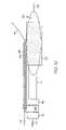
- an outer balloonmay replace the sheath of the above embodiments.
- the outer balloon in such instancesmay have the same qualities as the sheath as described in the embodiments above.
- the secondary lumenfurther comprises a secondary inflation lumen and the catheter further comprises a secondary balloon.
- the secondary balloonis external but adjacent to the sheath and prior to delivery the stent is disposed about the secondary balloon as well.
- the rotating collarincludes one or more inflation lumens for separate and/or simultaneous inflation of the primary and secondary balloons.
- the rotating collarcomprises one or more sealing mechanisms which when in a sealed state prevents or limits rotation of the collar but which seals the collar to define one or more of the inflation lumens so that one or more of the balloons may be inflated.
- the sealing mechanismcomprises one or more shape memory materials which may be moved between a free position and a sealed position upon exposure to a predetermined temperature, electrical signal, etc.(and/or for a predetermined period of time).
- the sealing mechanismis an inflatable seal which is in fluid communication with the secondary inflation lumen, such that when fluid is passed through the secondary inflation lumen to inflate the secondary balloon, the inflatable seal is expanded from a free state to a sealed state.
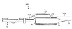
- FIG. 1is a perspective view of an embodiment of the invention wherein the assembly is shown in a pre-deployment configuration.
- FIGS. 2 a - dare cross-sectional views of sheath configurations.
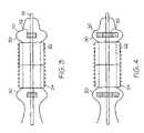
- FIG. 3is a perspective view of an embodiment of the invention wherein the assembly is shown having balloon cones on the balloon.
- FIG. 4is a perspective view of an embodiment of the invention wherein the assembly is shown having large diameter marking bands.
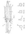
- FIG. 5is a perspective view of an embodiment of the invention wherein the assembly is shown illustrating the tether attachment and also the rotating collar and longitudinal locks.
- FIG. 6is a cross-sectional view of the rotating collar from view A-A of FIG. 5 .
- FIG. 7is a perspective view of an embodiment of the invention wherein the assembly is shown having an outer balloon in place of the sheath.
- FIG. 8is a perspective view of a catheter balloon illustrating the body portion and the cone portions of the catheter balloon.
- FIG. 9is a perspective view of an embodiment of the invention wherein the assembly is shown having a hypotube which is disposed in the second guide wire collar lumen.
- FIG. 10is a perspective view of an embodiment of the invention wherein the assembly is shown having a hypotube engaged to the collar.
- FIG. 11is a side view of an embodiment of the invention, comprising a rotating sheath assembly.
- FIG. 12is a side view of the embodiment shown in FIG. 11 shown configured for delivery of a stent.
- FIG. 13is a side perspective view of an embodiment of the invention comprising a stent, such as that shown in FIG. 12 .
- FIG. 14is a side perspective view of the stent shown in FIG. 13 wherein a side branch opening is shown formed from the enlargement of a cell opening in the stent wall.
- FIG. 15is a cross-sectional view of the stent of FIG. 14 .
- FIG. 16is a side view of an embodiment of the invention comprising a catheter assembly.
- the catheter assemblyis provided with a rotating collar.
- FIG. 17is a side view of the catheter assembly of FIG. 16 and further comprising the rotating sheath assembly and stent of FIG. 12 .
- FIGS. 18-19are cross-sectional views of an embodiment of the invention comprising a locking clip for use on a catheter such as is shown in FIGS. 16 and 17 , wherein the clip, when mounted on the catheter shaft adjacent to the rotating collar, prevents longitudinal displacement of the collar and the associated rotating sheath assembly.
- the clipwhen mounted on the catheter shaft adjacent to the rotating collar, prevents longitudinal displacement of the collar and the associated rotating sheath assembly.
- FIG. 18the clip is shown in an open, unlocked configuration for placement and removal from a catheter shaft.
- FIG. 19the clip is shown in the closed, locked configuration such as the clip would have when positioned on the catheter shaft.
- FIG. 20is a partial side view of an embodiment of the invention wherein the catheter assembly includes a pair of cone retaining sleeves for aiding in retaining the folded configuration of the balloon prior to balloon expansion.
- FIG. 21is a partial side view of an embodiment of the invention similar to that shown in FIG. 20 , but wherein each cone retaining sleeves further include radial ridges for preventing longitudinal displacement of the sleeve.
- FIG. 22is a perspective view of an embodiment of the invention comprising a removable protective sheath for retaining the balloon in the reduced or pre-delivery state.
- FIG. 23is a side view of an embodiment of the invention wherein the catheter assembly is depicted with the protective sheath shown in FIG. 22 in place prior to use of the catheter.
- FIG. 24is a side view of an embodiment of the invention wherein the catheter assembly of FIG. 17 is shown being advanced along a primary and secondary guide wire to a vessel bifurcation prior to delivery of the stent.
- FIG. 25is a side view of the stent depicted in FIG. 24 , wherein the stent has been delivered from the catheter assembly, by balloon expansion and the assembly subsequently withdrawn from the vessel(s).
- FIG. 26is a side view of the stent of FIG. 25 , depicted being seated within the vessel bifurcation by a pair of balloons, which are advanced individually along each guide wire and expanded within the stent and subsequently removed therefrom.
- FIG. 27is a side view of the stent shown in FIG. 26 , (now referred to as the primary stent) wherein a secondary stent has been deployed by a stent delivery catheter through the secondary opening of the primary stent.
- FIG. 28is a side view of an embodiment of the invention comprising a catheter assembly wherein the secondary guide wire lumen extends from the rotating collar, under the rotating sheath and out a secondary openings of the sheath and stent.
- FIG. 29is a cross-sectional view of the assembly shown in FIG. 28 .
- FIG. 30is a side view of an embodiment of the invention comprising a catheter assembly having dual balloons wherein the secondary balloon is positioned radially adjacent the rotating sheath, but substantially within a portion of the stent, the secondary balloon is thus rotatable about the primary balloon by the rotation of the sheath.
- FIG. 31is a perspective view of a catheter assembly having two inflation balloons, wherein the secondary balloon is in fluid communication with a secondary inflation lumen and the rotating collar provides a rotatable seal which allows the proximal portion of the secondary inflation lumen fluid communication with the distal portion of the secondary inflation lumen.
- FIG. 32is a perspective view of a portion of the assembly shown in FIG. 31 , wherein the secondary inflation lumen is provided with a substantially crescent shaped cross-sectional shape to provide the secondary inflation lumen with a lower profile and improved rotational interface with the catheter shaft or primary inflation lumen.
- FIGS. 33-34are side views of a configuration of rotating seal, shown in the open rotatable position and sealed fixed position respectively, for use in a catheter assembly such as is depicted in FIG. 31 .
- FIG. 35-36are side views of a configuration of rotating seal, shown in the open rotatable position and sealed fixed position respectively, for use in a catheter assembly such as is depicted in FIG. 31 .
- FIG. 1an assembly 10 is shown.
- the assemblyis designed to provide better axial and longitudinal positioning of a stent in a bifurcation site.
- the assembly 10has an outer catheter shaft 14 with an inner catheter shaft 16 defining a wire lumen 17 and an inflation lumen 18 extending from a proximal region of the catheter to a distal region of the catheter.
- the inner lumen 17is constructed such that it can be disposed about a guide wire which provides means for guiding the catheter to the treatment site.
- the inflation lumen 18provides a passage for the inflating fluid to both inflate and deflate the catheter balloon 20 .
- the catheter balloon 20is sealingly engaged at its proximal end 20 a to the outer shaft 14 and is sealingly engaged at its distal end 20 b to the inner shaft 16 .
- a sheath 22is disposed about the balloon 20 .
- the sheathis designed to be freely rotatable about the balloon.
- the sheath 22can be constructed of a low friction material such as PTFE or HDPE which allows the sheath to freely rotate about the balloon 20 .
- at least a portion of balloon 20may include a coating of one or more low friction materials or include one or more low friction materials in its construction.
- the assembly 10may be used to deliver a stent 24 to a vessel bifurcation.
- a stent 24is disposed about and crimped upon the sheath 22 .
- the rotatability of the sheath 22allows a stent 24 disposed thereabout to be freely rotated within a vessel or lumen to allow one or more openings of the stent to be aligned with a branch of the bifurcation.
- an outer layer 22 a of the sheath 22may be constructed of a softer material than that of the material used in constructing the inner layer 22 b of the sheath 22 .
- the softer outer layerwill provide improved stent securement upon crimping of the stent 24 .
- a soft polymeris one with a durometer hardness of less than about 55 D.
- Possible materials for the outer layerare a polymer like PEBAX (55D), a urethane, etc.
- the low friction inner layer 22 bcan be constructed of PTFE or HDPE.
- a second shaft 25 defining the second wire lumen 26is engaged along a portion of the sheath 22 .
- the sheathitself can also define the second wire lumen 26 .
- Rotational torque indicated by arrows 27may be applied to the sheath 22 when the catheter is advanced to the bifurcation site in the following manner:
- the assembly 10is advanced along two guide wires 29 and 44 as shown in FIG. 5 .
- the first guide wire 29is positioned in the primary passage or branch vessel and is disposed inside the inner lumen 17 of the catheter shaft 14 .
- the second guide wire 44diverges from the first guide wire 29 upon passage into the secondary branch in the region of the bifurcation.
- the inner lumen 17 of the stent delivery assembly 10is disposed about the guide wire 29 in the primary passage while the second wire lumen 26 of the stent delivery assembly 10 is disposed about the second guide wire which extends into the secondary passage of the bifurcation.
- a tether 34can also be added in order to limit the distal movement of the sheath 22 in relation to the inner shaft 16 .
- the tether 34can be attached directly to the sheath at tether engagement point 11 .
- the sheath or the outside balloonsubstantially freely rotates about the inner shaft 16 and/or balloon 20 .
- the sheath or outside balloonmay rotate less than a single degree or over 360 degrees in order to align at least one of the openings in the stent with a side branch lumen at a bifurcation site.
- FIGS. 2 a - 2 ccross-sections of different embodiments of the shown sheath 22 in the unexpanded state prior to the delivery of the stent are illustrated.
- the second shaft 25 defining the second wire lumen 26is engaged to the sheath 22 .
- a sheath having a second shaft 25 ais attached to the sheath 22 a .
- the sheath 22 ais arranged in a coil-like structure before deployment of the stent. During delivery of the stent, the sheath 22 a uncoils.
- FIG. 1cross-sections of different embodiments of the shown sheath 22 in the unexpanded state prior to the delivery of the stent are illustrated.
- the second shaft 25 defining the second wire lumen 26is engaged to the sheath 22 .
- a sheath having a second shaft 25 ais attached to the sheath 22 a .
- the sheath 22 ais arranged in a coil-like structure
- a sheath having a clam shell cross-sectionis shown in the unexpanded state.
- the second shaft 25 bis engaged to the sheath at an end of the sheath 22 b .
- a sheath prior to delivery of the stenthas a cross-section in the unexpanded state shaped in an accordion-like structure.
- the folds 28 in the unexpanded statecan be pressed down or wrapped as shown in FIG. 2 d.
- FIG. 3an embodiment is shown wherein the balloons end portions or cones 30 are provided with a diameter about the inner catheter shaft 16 greater than the cross-sectional diameter of the sheath 22 .
- the sheathis protected by the inclusion of one or more hubs, protrusions, marker bands 32 , etc. with a diameter sufficient to prevent the sheath from moving in a longitudinal direction.
- marker bands 32act like a dam on each end of the sheath 22 by forcing portions of the balloon radially outward such that these portions of the balloon 20 have a greater diameter than the diameter of the sheath 22 .
- the stent 24 in either or both the expanded and the unexpanded conditionsmay have a greater diameter than the cones 30 while the sheath 22 does not.
- FIG. 5an embodiment of the invention is shown wherein the assembly is provided with a safety tether 34 .
- the tether 34(shown in this figure overlapping the second guide wire 44 ) can be a simple pull wire that runs along the length of the catheter 10 and engages the sheath 22 .
- the tether 34can extend into the second wire lumen 26 and thereby engage the sheath 22 or the second shaft 25 at an engagement point 35 .
- the safety tether 34can also attach to the sheath 22 directly as shown in FIG. 1 at tether engagement point 11 .
- the catheter 10may include a rotating collar 36 having a second guide wire collar lumen 38 and an outer catheter shaft collar lumen 39 which is disposed about the outer catheter shaft 14 .
- a distal longitudinal lock 40 disposed about the catheter shaft and both adjacent and distal to the collar 36limits longitudinal movement of the collar 36 .
- the distal longitudinal lock 40has a diameter greater than the diameter of the outer catheter shaft collar lumen 39 .
- the proximal longitudinal lock 42 disposed about a second guide wire 44has a greater diameter than the second guide wire collar lumen 38 , thus limiting the wire 44 from distal movement beyond the point when the proximal longitudinal lock 42 comes into contact with the second guide wire collar lumen 36 .
- an outer balloon 46which rotates around the inner balloon 20 is used in place of a sheath 22 .
- the outer balloon 46is sealed at first end 48 and second end 50 of the catheter 10 .
- Balloon movement stoppers 52limit longitudinal movement of the balloons.
- the outer balloon 46can be constructed of a low friction material such as PTFE, HDPE and/or PEBAX which allows the outer balloon 46 to freely rotate about the inner balloon 20 .
- the stent 24is disposed about and crimped upon the outer balloon 46 . It should be noted that the outer balloon can also have multiple layers.
- An outer layer of the outer balloon 46may be constructed of a softer material than that of the material used in constructing the inner layer of the outer balloon 46 .
- the softer outer layermay provide improved stent securement upon crimping of the stent 24 .
- a soft polymeris one with a durometer hardness of less than about SSD.
- Possible materials for the outer layerare a polymer like PEBAX (55D), a urethane, etc.
- the low friction inner layer of the outer balloon 46can be constructed of PTFE or HDPE and/or other suitable materials.
- Gap 58(shown on only one end, first end 48 ) acts as a friction reducing mechanism between outer balloon seal site 54 and inner balloon seal site 56 .
- Gap 58includes a friction reducing fluid, a low friction material, a bearing system, etc., or any combination thereof.
- the cones 30 and body portion 60 of the catheter balloon 20are shown.
- the sheath 22is of the substantially same length as the body portion 60 of the catheter balloon 20 .
- the sheath 22is disposed substantially on the body portion 60 of the balloon 20 .
- the sheath 22extends longitudinally such that a portion of the sheath 22 is disposed about at least one of the cone portions 30 .
- a hypotube 64is engaged to the collar 38 and the sheath 22 .
- the hypotube 64may comprise stainless steel or it may comprise a polymer.
- the hypotube 64may be constructed to be spiral cut.
- the spiral cut 65may include scoring, cutting, indenting, perforating, puncturing, etc.
- the hypotube 64may thus be firm in the longitudinal direction but may also be flexible due to the spiral cut.
- FIGS. 9 and 10also illustrate embodiments having both the proximal longitudinal lock 42 and the distal longitudinal lock 40 disposed about the outer catheter shaft 14 rather than as shown in FIGS. 5 and 6 wherein one longitudinal lock is disposed about the guide wire 44 or safety tether 34 .
- FIG. 9specifically illustrates an embodiment wherein the hypotube 64 is disposed in the second guide wire collar lumen 38 .
- the hypotube 64may be disposed in only a portion of the second guide wire collar lumen 38 .
- the collar 36rotates along with the sheath 22 and thus may rotate simultaneously and/or with equal degrees of rotation.
- the hypotube 64is engaged to an outside surface of the collar 36 .
- engagement of the hypotube 64 to the collar 36 and sheath 22can be through chemical welding, heat welding, laser welding, chemical bonding, adhesives, fastening devices, etc.
- a rotating sheath assembly 100which comprises a tubular sleeve or sheath 102 and a positioning or secondary guide wire housing 104 , the housing 104 defines a secondary guide wire lumen 106 through which a secondary guide wire 108 may be passed.
- the housing 104may be constructed of a wide variety of materials including metal plastic, etc., in at least one embodiment the housing 104 is a hypotube 64 as has been previously described. In some embodiments the housing 104 is provided with one or more openings 110 along its length. In at least one embodiment the housing 104 is spiral cut to provide at least a continuous opening 110 which acts to provide improve the flexibility of the housing 104 .
- the secondary guide wire housing 104further comprises an inner shaft 103 , about which the hypotube 64 is disposed.
- the inner shaft 103is a flexible hollow tubular member which extends distally beyond the distal end of the hypotube 64 .
- This distal tip 105 of the inner shaft 103provides the housing with a flexible protective sheath about the guide wire 108 as it passes distally out of the secondary guide wire lumen 106 .
- Such a protective coveringprevents the guide wire 108 from excessively rubbing against the wall 201 of the vessel 199 , such as in the manner depicted in FIG. 24 , even where the secondary guide wire 108 exits the secondary lumen 106 at a significant angle.
- the inner shaft 103may be constructed of any of a variety of flexible materials such as: PEBAX, nylon, urethane, and/or other materials in a single layer, multi-layer and/or braided configuration.
- At least a distal portion of the housing 104is engaged to at least a proximal portion of the sheath 102 at an engagement site 112 .
- the manner or mechanism of engagement between the sheath and housing 104may be by bonding, welding, adhering adhesively engaging, mechanically engaging or otherwise connecting the surfaces of the respective sheath 102 and housing 104 .
- the sheath 102is a hollow tube of sheath material that is configured to be placed over the balloon 114 of a catheter assembly 116 , such as in the manner illustrated in FIGS. 16 and 17 .
- the sheath 102is further configured to be rotatable about the balloon 114 , even when a stent 120 has been positioned about and/or affixed to the sheath 102 .
- the sheath 102may be constructed of a variety of low friction materials such as PTFE, HDPE, etc.
- the sheath 102is at least partially constructed of a hydrophilic material, such as hydrophilic polymers such as; TECOPHLIC® material available from Thermedics Polymer Products, a division of VIASYS Healthcare of Wilmington, Mass.; TECOTHANE®, also available from Thermedics Polymer Products; hydrophilic polyurethanes, and/or aliphatic, polyether-based thermoplastic hydrophilic polyurethane; and any other material that provides the sheath 102 with the ability to rotate freely about the balloon 114 when in the “wet” state, such as when the catheter is exposed to body fluids during advancement through a vessel.
- hydrophilic polymerssuch as; TECOPHLIC® material available from Thermedics Polymer Products, a division of VIASYS Healthcare of Wilmington, Mass.; TECOTHANE®, also available from Thermedics Polymer Products; hydrophilic polyurethanes, and/or aliphatic, polyether-based thermoplastic hydrophilic polyurethane; and any other
- Suitable sheath materialsmay also provide the sheath with rotatability in the “dry”, or pre-insertion, state, but with the application of a greater amount of force than when in the wet state, such materials are referred to herein as being TECOPHLIC®.
- a sheath 102 at least partially constructed from TECOPHLIC® materialprovides the sheath 102 with the ability to rotate freely about the balloon 114 when in the “wet” state, such as when the catheter is exposed to body fluids during advancement through a vessel.
- the TECOPHLI® C sheath 102is also capable of rotation in the “dry”, or pre-insertion, state, but with the application of a greater amount of force than when in the wet state.
- a sheath 102 at least partially constructed from tecophilic materialprovides the sheath 102 with the ability to rotate freely about the balloon 114 when in the “wet” state, such as when the catheter is exposed to body fluids during advancement through a vessel.
- the tecophilic sheath 102is also capable of rotation in the “dry”, or pre-insertion, state, but with the application of a greater amount of force than when in the wet state.
- the sheath 102may be constructed of one or multiple materials, in one or more layers.
- the sheath 102may comprise an outer layer of a softer material than that of the material used in constructing an inner layer, such as has been previously described.
- the sheath 102may be comprised of a matrix of a first material 111 and have one or more supportive stripes, strands, members or areas of a second supportive material 113 within, external to or internal to such a matrix.
- composition of the sheath 102 materialmay include essentially any appropriate polymer or other suitable materials.
- suitable polymersinclude Hydrophilic Polyurethanes, Aromatic Polyurethanes, Polycarbonate base Aliphatic Polyurethanes, Engineering polyurethane, Elastomeric polyamides, block polyamide/ethers, polyether block amide (PEBA, for example available under the trade name PEBAX), and Silicones, Polyether-ester (for example a polyether-ester elastomer such as Arnitel available from DSM Engineering Plastics), Polyester (for example a polyester elastomer such as Hytrel available from Du Pont), or linear low density polyethylene (for example Rexell).
- Hydrophilic PolyurethanesAromatic Polyurethanes, Polycarbonate base Aliphatic Polyurethanes, Engineering polyurethane, Elastomeric polyamides, block polyamide/ethers, polyether block amide (PEBA, for example available under the trade name PEBAX), and Silicones
- Example of suitable re-inforcing materials whether alone or blended with other materials, mixtures or combination or copolymersinclude all Polyamides (for example, Durethan available from Bayer or Cristamid available from ELF Atochem), polyethylene (PE). Marlex high-density polyethylene, polyetheretherketone (PEEK), polyimide (PI), and polyetherimide (PEI), liquid crystal polymers (LCP), and Acetal (Delrin or Celcon).
- Polyamidesfor example, Durethan available from Bayer or Cristamid available from ELF Atochem
- PEpolyethylene
- Marlex high-density polyethylenepolyetheretherketone
- PIpolyimide
- PEIpolyetherimide
- LCPliquid crystal polymers
- AcetalDelrin or Celcon
- the inner surface of the sheath 102 or the outer surface of the balloon 114may include a coating of one or more low friction materials or include one or more low friction materials in its construction.
- a coating 401is shown in FIG. 16 , as being depicted on the surface of the balloon 114 before assembly 100 has been placed thereabout, such as is depicted in FIG. 17 . Coating 401 may however by placed between the balloon 114 and sheath 102 at any time.
- a suitable coating materialinclude but are not limited to: hydrogel, silicon, and/or BIOSLIDE® .available from SciMed Life Systems, Inc. of Maple Grove Minn.
- the sheath 102is configured to be freely rotatable about a balloon of a catheter even when a stent 120 , such as is shown in FIG. 12 is crimped onto the sheath 102 .
- a proximal portion 122 of the stent 120is also disposed about at least a portion of the secondary guide wire housing 104 .
- at least a portion of the housing 104 and/or the secondary guide wire 108extends distally through a cell opening 130 of the stent 120 .
- Stent 120may be a stent, such as is shown in FIG. 13 , which is at least partially constructed of a plurality of interconnected struts, connectors or members 132 .
- the stent 132defines a proximal opening 134 , a distal opening 136 and a flow path 138 therebetween.
- the cell openings 130are in fluid communication with the flow path 138 .
- the members 132 that define the selected cell opening 130 amay be distorted or modified in order to accommodate the passage of secondary guide wire 108 and/or the secondary guide wire housing 104 therethrough.
- the modified cell opening 130 ahereinafter referred to as secondary opening 130 a , is positioned on the stent 120 between the proximal opening 134 and the distal opening 136 .
- the manner in which the secondary opening 130 a , the members 132 adjacent thereto, and to an extent the stent 120 itself, are modified or distorted by the position of the secondary guide wire and/or secondary guide wire housingis depicted in FIGS. 14 and 15 .
- the distortion of the secondary opening 130 a and the adjacent members 132is of a minimal extent, and is provide only to allow sliding passage of the secondary guide wire 108 , and if desired a distal portion of the secondary guide wire housing 104 , through the secondary opening 130 a .
- the actual size of the secondary opening 130 amay be substantially similar, or only marginally different than that of the surrounding cell openings 130 .
- stent 120may be a standard “single vessel” stent that is provided with a secondary opening 130 a in the manner described above, the stent 120 may also be a bifurcated stent having a trunk or stem portion, with one or more leg portions and/or branch openings adjacent thereto, through one of which the secondary guide wire may be passed.
- Such bifurcated stents and stent assembliesare well known in the art.
- the stent 120may be configured to deliver one or more therapeutic agents to a delivery site such as within the vessel 199 or one or more areas adjacent thereto, such as shown in FIGS. 24-27 .
- one or stent members 132such as is shown in FIG. 13 , maybe configured to include one or more holes, notches, or other surface features to which one or more therapeutic agents 400 may be placed for delivery to the aneurysm site.
- a therapeutic agentmay be placed on the stent in the form of a coating.
- the coatingincludes at least one therapeutic agent and at least one polymer.
- a therapeutic agentmay be a drug, a non-genetic agent, a genetic agent, etc.
- suitable non-genetic therapeutic agentsinclude but a re not limited to: anti-thrombogenic agents such as heparin, heparin derivatives, urokinase, and PPack (dextrophenylalanine proline arginine chloromethylketone); anti-proliferative agents such as enoxaprin, angiopeptin, monoclonal antibodies capable of blocking smooth muscle cell proliferation, hirudin, and acetylsalicylic acid; anti-inflammatory agents such as dexamethasone, prednisolone, corticosterone, budesonide, estrogen, sulfasalazine, and mesalamine; antineoplastic/antiproliferative/anti-miotic agents such as paclitaxel, 5-fluorouracil, cisplatin, vinblastine, vincristine, epothilones, endo
- an agentmay include but is not limited to: anti-sense DNA and RNA; DNA coding for anti-sense RNA, tRNA or rRNA to replace defective or deficient endogenous molecules; angiogenic factors including growth factors such as acidic and basic fibroblast growth factors, vascular endothelial growth factor, epidermal growth factor, transforming growth factor ⁇ and ⁇ , platelet-derived endothelial growth factor, platelet-derived growth factor, tumor necrosis factor ⁇ , hepatocyte growth factor and insulin like growth factor; cell cycle inhibitors including CD inhibitors, thymidine kinase (“TK”) and other agents useful for interfering with cell proliferation; at least one of the family of bone morphogenic proteins (“BMP's”) such as BMP-2, BMP-3, BMP-4, BMP-5, BMP-6 (Vgr-1), BMP-7 (OP-1), BMP-8, BMP-9, BMP-10, BMP-11, BMP-12, BMP-13
- BMP'sbone morphogenic proteins
- BMP-2, BMP-3, BMP-4, BMP-5, BMP-6 and BMP-7Any of BMP-2, BMP-3, BMP-4, BMP-5, BMP-6 and BMP-7; dimeric proteins such as homodimers, heterodimers, or combinations thereof, alone or together with other molecules; molecules capable of inducing an upstream or downstream effect of a BMP such as “hedgehog” proteins, or the DNA's encoding them and any combinations thereof.
- the cellular materialmay include but is not limited to: cells of human origin (autologous or allogeneic); cells of non-human origin (xenogeneic) and any combination thereof.
- cellular materialinclude but are not limited to the following:
- a therapeutic agentcomprises at least one polymer agent or coating
- the at least one coatingmay include but is not limited to: polycarboxylic acids; cellulosic polymers, including cellulose acetate and cellulose nitrate; gelatin; polyvinylpyrrolidone; cross-linked polyvinylpyrrolidone; polyanhydrides including maleic anhydride polymers; polyamides; polyvinyl alcohols; copolymers of vinyl monomers such as EVA; polyvinyl ethers; polyvinyl aromatics; polyethylene oxides; glycosaminoglycans; polysaccharides; polyesters including polyethylene terephthalate; polyacrylamides; polyethers; polyether sulfone; polycarbonate; polyalkylenes including polypropylene, polyethylene and high molecular weight polyethylene; halogenated polyalkylenes including polytetrafluoroethylene; polyurethanes; polyorthoesters; proteins; polypeptides; silicones; silox
- an example of a suitable polymer agent or coatingcomprises block copolymers comprising at least one A block and at least one B block.
- the A blocksare preferably soft elastomeric blocks, which are based upon one or more polyolefins, or other polymer with a glass transition temperature at or below room temperature.
- the A blockscan be polyolefinic blocks having alternating quaternary and secondary carbons of the general formulation: —(CRR′—CH 2 ) n —, where R and R′ are, independently, linear or branched aliphatic groups such as methyl, ethyl, propyl, isopropyl, butyl, isobutyl and so forth, or represent cyclic aliphatic groups such as cyclohexane, cyclopentane, and the like, either with or without pendant groups.
- Preferred polyolefinic blocksinclude polymeric blocks of isobutylene,
- a blocksinclude silicone rubber blocks and acrylate rubber blocks.
- the B blocksare preferably hard thermoplastic blocks with glass transition temperatures significantly higher than the elastomeric A blocks which, when combined with the soft A blocks, are capable of, inter alia, altering or adjusting the hardness of the resulting copolymer to achieve a desired combination of qualities.
- B blocksinclude polymers of methacrylates or polymers of vinyl aromatics. More specific examples of B blocks include blocks that are (a) formed from monomers of styrene
- styrene derivativese.g., ⁇ -methylstyrene, ring-alkylated styrenes or ring-halogenated styrenes or other substituted styrenes where one or more substituents are present on the aromatic ring
- styrenic blocksor “polystyrenic blocks” or are (b) formed from monomers of methylmethacrylate, ethylmethacrylate, hydroxyethyl methacrylate or mixtures of the same.
- the block copolymersare provided in a variety of architectures, including cyclic, linear, and branched architectures.
- Branched architecturesinclude star-shaped architectures (e.g., architectures in which three or more chains emanate from a single region), comb architectures (e.g., copolymers having a main chain and a plurality of side chains), and dendritic architectures (including arborescent or hyperbranched copolymers).
- block copolymersinclude the following: (a) BA (linear diblock), (b) BAB or ABA (linear triblock), (c) B(AB) n or A(BA) n (linear alternating block), or (d) X-(AB) n or X-(BA) n (includes diblock, triblock and other radial block copolymers), where n is a positive whole number and X is a starting seed, or initiator, molecule.
- Other examples of block polymersinclude branched block copolymers such as dendritic block copolymers, wherein at least one of the A and B blocks is branched, for instance, where the A blocks are branched and are capped by the B blocks.
- the assembly 100may be slid onto a catheter 116 , such as is shown in FIGS. 16-17 so that the sheath 102 is rotatingly disposed about the balloon 114 and a proximal portion 140 of the secondary guide wire housing 104 is engaged to a rotating collar 150 .
- the collar 150is engaged to the proximal portion 140 of the secondary guide wire housing 104 by any engagement mechanism desired, such as welding, bonding, mechanical engagement, adhesive engagement, etc.
- the proximal portion 140 of the secondary guide wire housing 104 and the collar 150are engaged externally at engagement site 142 .
- the secondary guide wire housing 104may be passed at least partially through the collar 150 , and/or the collar 150 may define a lumen through which the secondary guide wire 108 may be passed before entering into the secondary guide wire housing 104 .
- Collar 150may be a substantially cylindrical member that is disposed about the shaft 144 of the catheter 116 at a position proximal of the balloon 114 .
- the collar 150may be characterized as defining a catheter shaft lumen 146 through which the catheter shaft 144 is passed.
- the collar 150defines a catheter shaft lumen 146 which has a diameter greater than the outer diameter of the shaft 144 .
- one or more lubricious substancesmay be placed between the collar 150 and the shaft 144 to further encourage free rotation therebetween.
- While the rotating collar 150is free to rotate about the shaft 144 , in some embodiments it will also be capable of being longitudinally displaced along the shaft 144 as well. As such, in some embodiments one or more locks or hubs 152 may be affixed about the shaft 144 on one or both sides of the collar 150 to prevent or limit the potential longitudinal displacement of the collar 150 relative to the shaft 144 .
- a lock 152comprises a body 154 which defines a catheter shaft engagement area 155 .
- the body 154is divided into at least two sections 156 and 158 which are pivotally moveable between an open position, shown in FIG. 18 , and a closed or secured position (about the catheter shaft 144 ), shown in FIG. 19 .
- the sections 156 and 158are pivotally engaged to one another by apivot 160 .
- the body 154may be two completely separatable sections 156 and 158 , may be a single member with sections 156 and 158 flexibly and pivotally engaged to one another, etc.
- section 156defines a receiving chamber 162 having a grasping mechanism 164 for retainingly engaging a locking tab 166 of the adjacent section 158 .
- the chamber 162 and/or tabl 66may comprise any of a plurality of engagement mechanisms to fixedly engage the section to one another. For example, they may employ one or more complimentary surface features which securingly engage the adjacent surfaces of the chamber 162 and tab 166 .
- a lock 152may have any external shape desired and is preferably shaped and sized to have a minimum of profile and shape so as to not interfere with the advancement and/or trackability of the catheter 116 .
- a lock 152When secured about the catheter shaft 144 , adjacent to the collar 150 , a lock 152 will prevent the collar 150 from being longitudinally displaced along the catheter shaft 144 in the direction of the lock 152 . Where two locks 152 surround the collar 150 , the locks may be spaced so as to eliminate longitudinal displacement of the collar 150 or merely limit such displacement to a desired extent.
- the assembly 100may be affixed to a catheter 116 at any time prior to use in a stent delivery procedure.
- the sheath 102is free to rotate about the balloon 114 the sheath may not aid significantly in maintaining the balloon in a reduced, and typically folded, state prior to inflation of the balloon 114 and expansion of the stent 120 .
- Each of the proximal portion 174 and distal portion 176 of the balloon 114may include at least a part of the balloon cone and in some embodiments at least a respective end portion of the balloon body adjacent thereto.
- the second portion 180 of each sleeveis engaged to the catheter shaft 144 at an area adjacent to the balloon 114 .
- the sleeves 170 and 172When the balloon is in the reduced state the sleeves 170 and 172 have sufficient radial strength to retain the ends of the balloon 114 in the folded and reduced profile configuration. By retaining the ends of the balloon 114 in the folded configuration, absent inflation of the balloon 114 , the balloon will tend to remain folded or reduced.
- the radially contractive force of first portion 178 of each sleeveis overcome by the outwardly acting force of the balloon's inflation thereby allowing the balloon to unfold or expand from the reduced state to the expanded state.
- the sleeves 170 and 172may be configured to retract or otherwise substantially withdraw from the end portions 174 and 176 of the balloon 114 .
- the sleevesmay be constructed from any of a variety of materials such as are described in U.S. Pat. No. 6,443,980; U.S. Pat. No. 6,221,097; U.S. Pat. No. 6,554,841; U.S. Pub. application No. 2002-0038140 A1; and U.S. Pub. application No. 2002-0038141 A1, the entire content of each of which are incorporated herein by reference.
- each sleeve 170 and 172may comprise a thickened region or lip 182 which provides the sleeves 170 and 172 with a raised profile of sufficiency to engage each end of the rotatable sheath 102 .
- the sleeveswill act in a manner similar to that of the previously described locks by preventing pr reducing the potential longitudinal displacement of the sheath 102 and the entire assembly 100 relative to the balloon 114 and catheter 116 .
- One or more sleeves 170 and/or 172 with lips 182may be used in conjunction with or as an alternative to locks 152 to aid in controlling and/or eliminating potential longitudinal displacement of the assembly 100 relative to the catheter 116 .
- an assembly 100 equipped catheter 116is provided with a protector 190 that is disposed about the end portions 174 and 176 of the balloon 114 , and in at least one embodiment, one or more adjacent portions of the catheter 116 such as the catheter tip 105 .
- Protector 190is intended to retain the balloon 114 in the reduced folded configuration prior to its removal before the system 300 is utilized in a delivery procedure.
- the protector 190comprises a proximal housing portion 194 , a distal housing portion 196 and an intermediate portion 198 extending therebetween.
- the protector 190may be a cylindrical member with one or both ends being substantially opened or closed.
- at least a portion of the protector, such as the proximal housing portion 194defines a longitudinal opening or slit 200 which allows the proximal housing portion 196 to be slid on and around the proximal end portion 174 of the balloon 114 once the distal housing portion 196 is positioned about the proximal end portion 176 of the balloon 114 and/or the catheter tip 105 .
- the protector 190is removed by pulling the proximal housing portion 194 radially away from the balloon 114 along the slit 200 until the housing 194 is fully removed from about the balloon 114 and then moving the protector 190 in a more longitudinal direction to slide the distal housing portion 196 off of the end of the catheter.
- the slit 200may extend from the proximal housing portion 194 to other regions of the protector 190 including the distal housing portion 196 .
- the intermediate portion 198is a single member of material running along side a portion of the external surface of the stent 120 .
- the intermediate portion 190may have a more substantially tubular configuration to provide increased coverage to the stent 120 and thus better protection from physical contact as well.
- the catheter 116is equipped with one or more sleeves 170 and 172 as well as protector 190 in combination.
- the protectormay be additionally configured and constructed of any suitable material such as is described in U.S. Pat. No. 5,893,868; U.S. Pat. No. 6,152,944; U.S. Pat. No. 6,416,529; U.S. Pat. No. 6,613,067; U.S. Pat. No. 6,132,450; U.S. Pub. application No. 2002-0116045-A1; and U.S. Pub. application No. 2002-0120320-A1, the entire contents of each of which being incorporated herein by reference.
- one or more of the various elements described hereinare at least partially constructed of a radiopaque material.
- the assembly 100may be considered to include the rotating collar 150 .
- Such an assembly 100is thus freely rotatable about the catheter shaft 144 , by way of collar 150 , as well as rotatable about the balloon 114 of the catheter 116 , by way of the rotatable sheath 102 .
- the system 300 described herein including the catheter 116 , assembly 100 and stent 120is utilized in a stent delivery procedure by being advanced along a primary guide wire 107 and the secondary guide wire 108 , such as in the manner shown in FIG. 24 .
- the guide wires 107 and 108are inserted into the vessel 199 and advanced therethough to a vessel bifuircation 203 whereat the primary guide wire 107 continues along the vessel 199 or primary vessel branch 205 and the secondary guide wire 108 is advanced in to a side branch vessel 207 .
- the assembly 100is advanced along the secondary guide wire 108 via the secondary guide wire lumen 106 , which is defined by the secondary guide wire housing 104 .
- the catheter 116is advanced along the primary guide wire 107 , which extends through a primary guide wire lumen 204 defined by the catheter shaft 144 .
- the catheter shaft 144also defines a primary inflation lumen 211 which is in fluid communication with the balloon 114 for inflation thereof.
- the primary inflation lumen 211 and the primary guide wire lumen 204are one and the same within the confines of the shaft 144 , but the primary inflation lumen 211 terminates within the balloon interior, while the primary guide wire lumen 204 extends through the balloon and out the catheter tip 105 .
- the assembly 100 and stent 120will be rotated into a position which aligns the secondary opening of the stent 130 a with the opening 209 of the side branch vessel 207 into which the secondary guide wire 108 extends.
- the capacity to rotate the assembly 100 and the associated stent 120 into position in this manneravoids the need to apply rotational torque to the catheter 116 as all rotational activity is provided by the rotating assembly 100 which will rotate according to the path established by the secondary guide wire 108 and more especially, according to the divergence of the path established by the secondary guide wire 108 and primary guide wire 107 shown in FIG. 24 .
- the balloon 114is inflated or otherwise expanded in the normal manner.
- the expanding balloon 114will engage the sheath 102 , thereby interrupting the sheath's ability to rotate about the balloon 114 and ensuring an accurate deployment of the stent 120 .
- the sheath 102so to does the sheath 102 thus allowing the stent 120 to be expanded and deployed into the vessel 199 as is shown in FIG. 24 .
- the stent 120may require additional expansion in order to better engage the wall 201 of the vessel 199 .
- one or more so-called “kissing” or seating balloons 210 and 212may be advanced along the guide wires 107 and 108 and into the flow path of the stent 120 and expanded therein in order to more securely engage the stent 120 against the vessel wall 201 .
- itmay be desired to provide the secondary opening 130 a by the expanding balloon with an enlarged area.
- one of the kissing balloons 210 and 212maybe advanced through the secondary opening 130 a . When the balloon is expanded therein, the force applied to the members 132 adjacent to the secondary opening 130 a will tend to further distort the members 132 away from one another thereby enlarging the size of the secondary opening 130 a.
- a secondary stent 121may be advanced and/or deployed adjacent to, through, and/or or at least partially within the secondary opening 130 a to provide complete stent support to the vessel bifurcation 203 .
- FIGS. 28 and 29an alternative embodiment to the system 300 is shown wherein the rotatable sheath 102 is further disposed about the secondary guide wire housing 104 , and is likewise rotatable thereabout.
- the sheath 102defines a secondary sheath opening 131 through which the secondary guide wire housing 104 is passed.
- the secondary guide wire housing 104may be passed at least partially through the collar 150 , and/or the collar 150 may define a lumen 151 through which the secondary guide wire 108 and/or housing 104 may be passed before entering into the secondary guide wire housing 104 .
- the system 300comprises a primary balloon 114 and a secondary balloon 115 .
- one or more of the guide wire lumensmay also act as an inflation lumen or the guide wire lumens and inflation lumens may be distinct.
- the secondary balloon 115is external to the sheath 102 , the sheath 102 , stent 120 and secondary balloon 115 are all rotatable about the primary balloon 114 prior to expansion thereof
- the secondary balloon 115will typically be limited in its ability to rotate about the primary balloon 114 to at most two full rotations 720 degrees. In some embodiments rotation will be limited to a single full rotation or 360 degrees.
- the system 300 shownalso employs a two balloon configuration.
- the catheter shaft 144defines a primary guide wire lumen 204 which also defines a primary inflation lumen 211 which is in fluid communication with the balloon 114 , such as in the manner previously described.
- Running adjacent to the shaft 144is a proximal secondary inflation lumen housing 213 , which defines a proximal secondary inflation lumen 215 which terminates at the collar 150 and is in fluid communication therewith.
- the proximal secondary inflation lumen 215 and the primary inflation lumen 211may be a common lumen or separate lumens contained within the shaft 144 .
- the collar 150comprises two portions: a collar housing 220 and a rotatable portion 222 at least partially contained within the housing 220 and rotatable relative thereto.
- the shaft 116along with the primary inflation lumen 211 and primary guide wire lumen 204 , extends through the collar 150 .
- the rotatable portion 222rotates freely about the shaft 144 when the collar 150 is in the unsealed state, which is discussed in greater detail as follows.
- the collar housing 220defines a fluid directing chamber 224 which is in fluid communication with the proximal secondary inflation lumen 215 .
- an inflation fluidindicated by arrow 226
- the pressure caused by the fluid 226 passing into the chamber 224or some other/additional activating mechanism or trigger, activates a sealing mechanism 230 between the housing 220 and the rotatable portion 222 .
- Activation of the sealing mechanism 230places the collar 150 in a sealed state wherein the rotatable portion 222 is no longer capable of freely rotating relative to the housing 220 and/or the catheter shaft 144 .
- the fluid 226will move into the distal secondary inflation lumen 228 of the distal secondary inflation lumen housing 231 which is in fluid communication with the fluid directing chamber 224 via the rotating portion 222 as well as the secondary balloon 115 .
- the distal secondary inflation lumen housing 231defines a sealed port 232 through which the secondary guide wire housing 104 may enter the lumen 228 and pass through the secondary balloon 115 , in the manner shown in FIG.31 .
- the secondary guide wire housing 104 and associated secondary guide wire lumen 106may be externally adjacent to the distal secondary inflation lumen housing 231 .
- one or more of the various portions of the catheter shafts, lumens and housingsmay be provided with a substantially crescent shape to provide the overall system 300 with the lowest possible profile.
- An example, of such a provisionis shown in FIG. 32 wherein the distal secondary inflation lumen housing 231 has a substantially crescent shaped cross-section.
- the housing 231may be in a more intimate contact with the catheter shaft and/or rotatable sheath as the system 300 is advanced through the tortuous confines of the vasculature.
- the collar 150includes a sealing mechanism 230 which is actuatable to provide the collar 150 , and more particularly the interface of the housing 220 and the rotatable portion 222 , with a sealed state, wherein inflation fluid 226 may be passed from the fluid directing chamber 224 , through the rotating portion 222 and eventually to the secondary balloon 115 ; and an unsealed state wherein the rotatable portion 222 remains free to rotate within and/or adjacent to the housing 220 .
- a sealing mechanism 230which is actuatable to provide the collar 150 , and more particularly the interface of the housing 220 and the rotatable portion 222 , with a sealed state, wherein inflation fluid 226 may be passed from the fluid directing chamber 224 , through the rotating portion 222 and eventually to the secondary balloon 115 ; and an unsealed state wherein the rotatable portion 222 remains free to rotate within and/or adjacent to the housing 220 .
- FIGS. 33 and 34A first embodiment of a sealing mechanism 230 is shown in FIGS. 33 and 34 .
- the collar 150employs a shape memory collar or ring 240 which is in conductive communication with at least one conducting wire, sleeve or member 242 .
- the rotating portion 222 and the ring 240are spaced apart to allow free rotation of the rotating portion 222 within the housing 220 .
- the ring 240is actuated by a conductive signal, indicated by arrow 244 shown in FIG.
- the ring 240will expand or otherwise alter its configuration to attain a pre-programmed state which causes the ring 240 or portion thereof, to extend radially inward to engage the rotating portion 222 , thereby sealing the rotating portion 222 against the housing 220 .
- fluid 226is now free to flow through and from the fluid directing chamber 224 , through the now immobilized rotatable portion 222 and on through the distal secondary inflation lumen 228 and the secondary balloon.
- the ring 240may be any sort of shape memory material or materials desired, such as nitinol, shape memory polymer, etc. As such, the ring 240 may be actuated by any sort of conductive signal 244 which is known to cause a shape memory material to transform from a first state to a preprogrammed second state.
- FIGS. 35 and 36Another embodiment of a sealing mechanism 230 is shown in FIGS. 35 and 36 .
- the rotatable portion 222defines one or more expandable inflation chambers 250 which are in fluid communication with the fluid directing chamber 224 .
- the fluidwill enter one or more inflation chamber ports 252 which will allow the fluid 226 to fill the chambers 250 from an unexpanded and unsealed state shown in FIG. 35 to an expanded and sealed state shown in FIG. 36 .
- the rotation of the rotatable portion 222remains unimpeded by the reduced diameter of the unexpanded chambers 250 .
- the rotatable portion 222becomes engaged to the housing 220 via the greater diameter of the expanded chambers 250 . Once the collar 150 is placed in the sealed state in this manner the fluid 226 is free to pass through the rotatable portion 222 and on through the distal secondary inflation lumen 228 .
- any dependent claim which followsshould be taken as alternatively written in a multiple dependent form from all prior claims which possess all antecedents referenced in such dependent claim if such multiple dependent format is an accepted format within the jurisdiction (e.g. each claim depending directly from claim 1 should be alternatively taken as depending from all previous claims).
- each claim depending directly from claim 1should be alternatively taken as depending from all previous claims.
- the following dependent claimsshould each be also taken as alternatively written in each singly dependent claim format which creates a dependency from a prior antecedent-possessing claim other than the specific claim listed in such dependent claim below.
Landscapes
- Health & Medical Sciences (AREA)
- Engineering & Computer Science (AREA)
- Biomedical Technology (AREA)
- Life Sciences & Earth Sciences (AREA)
- Oral & Maxillofacial Surgery (AREA)
- Transplantation (AREA)
- Heart & Thoracic Surgery (AREA)
- Vascular Medicine (AREA)
- Cardiology (AREA)
- Animal Behavior & Ethology (AREA)
- General Health & Medical Sciences (AREA)
- Public Health (AREA)
- Veterinary Medicine (AREA)
- Materials For Medical Uses (AREA)
- Media Introduction/Drainage Providing Device (AREA)
- Toys (AREA)
Abstract
Description
- SP—(side population cells) These cells are thought to be some of the most primitive adult stem cells. They are isolated by a specific FACS technique utilizing the ability of SP cells to exclude Hoechst dye from the nucleus. In addition to bone marrow, SP cells have been isolated from most tissues, including: cardiac and skeletal muscle. By the more common surface protein identification these cells are Lin−, Sca-1+, c-Kit+, CD43+, CD45+, CD34−
- Lin−—(lineage negative cells) This group of cells is isolated from the bone marrow and all cells which have differentiated to a specific lineage (e.g. red blood cells) have been removed. Therefore leaving all of the stem and progenitor cells. This is beneficial because all primitive cells remain, but may reduce efficiency by including irrelevant, primitive cell types.
- Lin−CD34−—Although CD34+ cells have received much attention, many articles have been published lately which suggest the most primitive bone marrow derived stem cells are CD34−
- Lin−CD34+—Presence of the cell surface protein CD34 has been used to identify hematopoietic stem cells. However, the marker is also present on progenitor cells and white blood cells of various levels of maturity.
- Lin−cKit+—cKit is the cell surface receptor for stem cell factor, and therefore a logical choice for stem cell selection. Most widely studied from bone marrow sources, but have also been isolated from the heart.
- MSC—(mesenchymal stem cells) Named so because ordinarily these cells differentiate into cells of mesenchymal tissues (e.g. bone, cartilage, fat), but may also differentiate into cardiomyocytes under certain conditions. Easily isolated from bone marrow and, unlike hematopoietic stem cells, proliferate in vitro. A subpopulation of MSCs has been shown to self-renew faster and have a greater potential for multipotential differentiation than the general MSC population. D. Prockop from Tulane U. is publishing in this area.
- Cord Blood Cells—Derived from the blood remaining in the umbilical vein following child birth. This blood has been shown to contain a higher percentage of immature stem cells or progenitor cells. Typically, a matched donor must be found for patients, but a lower incidence of graft versus host disease compared to stem cell isolation from adult blood has been reported. Disadvantages include: insufficient cell number in small blood volumes, unforeseen congenital defects, and contamination by mother's blood which is likely not HLA matched.
- Cardiac or other tissue derived stem cells—Most work to date has focused on isolating stem cells from bone marrow. This is due to extensive work in improving bone marrow transplants for chemotherapy and leukemia treatments. However, there is evidence that similar stem cells which can be identified by similar means (e.g. SP, cKit) can be isolated from other tissues (e.g. fat, cardiac muscle).
- Whole bone marrow—An “it's in there” approach where whole bone marrow (filtered for bone particles) is transplanted. Benefits include: little processing, all stem and progenitor cells are present, and matrix proteins and growth factors may also be present. Downside—if one or two stem cell types are responsible for cardiac improvement they will only be present in very low numbers.
- BM-MNCs—(bone marrow mononuclear cells) Separated from whole bone marrow by a density gradient centrifugation procedure, this population contains non-granular white blood cells, progenitor cells, and stem cells.
- EPCs—(endothelial progenitor cells) Isolated from bone marrow based on cell surface markers, these cells will become endothelial cells. In theory, these cells will form new blood vessels when delivered to ischemic tissue.
- Skeletal myoblasts—(or satellite cells) These cells are responsible for the regeneration of skeletal muscle following injury. They have the ability to fuse with other myoblasts or damaged muscle fibers. Cardiac muscle therapies assume these cells can integrate into the host tissue and improve tissue properties or functionally participate in contraction.
- MDCs—(muscle derived cells) A population of cells isolated from adult skeletal muscle which are similar to myoblasts. The isolation technique preplating entails collecting cells which attach to culture dishes at different times after biopsy. Cells with the best potential plate in the 6thgroup and takes several days to obtain. Investigators working with these cells claim they are a refined population of myoblasts and should result in higher engraftment efficiencies and efficacious procedures.
- Go cells—Recently isolated from adult skeletal muscle, these non-satellite cells express GATA-4 and, under certain in vitro growth conditions, progress to spontaneously beating cardiomyocyte-like cells.
- Endothelial cells—Transplantation of autologous endothelial cells along with a fibrin matrix induced angiogenesis and improved cardiac function in an ischemic sheep model.
- Adult cardiomyocytes
- Fibroblasts—Easily obtained from adult tissues, fibroblasts may provide growth factors or participate in the would healing response. Fibroblast play a critical role in wound healing; the synthesis and deposition of extracellular matrix. Fibroblasts commonly become contractile in wound healing environments.
- Smooth muscle cells—Isolated from arteries, these cells may participate or encourage angiogenesis and/or beneficial cardiac remodeling following MI.
- MSCs+5-aza—Culture of mesenchymal stem cells with 5-aza forces differentiation into cardiomyocytes. These cells beat spontaneously after treatment.
- Adult cardiac fibroblasts+5-aza—In theory, in vitro treatment of cardiac fibroblasts with 5-aza will result in differentiation into myogenic cells.
- Genetically modified cells—Isolation of cells from the patient and genetically modifying them in vitro to encourage production of proteins or differentiation into a cell type which will be beneficial for treating heart failure.
- Tissue engineered grafts—Isolation of cells from the patient which are then seeded onto and cultured within resorbable scaffolds (e.g. collagen, PLGA). These cell seeded constructs are then implanted into the patient.
- MyoD scar fibroblasts—MyoD family of transcription factors prompt skeletal muscle cell differentiation in fibroblasts. Procedure involves isolation of cardiac scar fibroblasts, genetic transfection with MyoD in vitro and delivery of the cells to the heart to encourage myogenesis.
- Pacing cells—Genetically modified fibroblasts which become electrically conducting and signal generators.
- Embryonic stem cell clones—Use of cloning technology to produce cardiomyocytes, progenitors, or stem cells which are genetically identical to the patient.
- Embryonic stem cells—These cells are the most primitive of cells and will differentiate into functional cardiomyocytes under certain conditions. Both political and technological hurdles must be overcome before commercialization of this technology.
- Fetal or neonatal cells—Isolated from the heart of donors, these cells may incorporate into host tissue without immune rejection. Some cardiomyocyte progenitor cells must be present due to the continued growth of the heart in fetal and neonatal humans.
- Immunologically masked cells—Allogeneic cell sources (e.g. donor cardiomyocytes) are currently unfeasible due to immune rejection. However, masking technologies have been developed which could make this technology feasible.
- Tissue engineered grafts—Isolation of cells from a donor which are then seeded onto and cultured within resorbable scaffolds (e.g. collagen, PLGA). These cell seeded constructs are then implanted into the host or recipient.
- Genetically modified cells—Isolation of cells from a donor and genetically modifying them in vitro to encourage production of proteins or differentiation into a cell type which will be beneficial for treating heart failure. The modified cells will then be transplanted into the host or patient.
- Teratoma derived cells—A teratocarcinoma is a form of cancer in which the tumor is composed of a heterogeneous mixture of tissues. Through isolation of cells from this tumor and in vitro manipulation and culture a neuronal cell line has been developed. Layton Biosciences has successfully used these cells to form new brain tissue in stroke patients. Similar techniques may be used to produce a myogenic cell line.

(i.e., polymers where R and R′ are methyl groups). Other examples of A blocks include silicone rubber blocks and acrylate rubber blocks.

styrene derivatives (e.g., α-methylstyrene, ring-alkylated styrenes or ring-halogenated styrenes or other substituted styrenes where one or more substituents are present on the aromatic ring) or mixtures of the same, collectively referred to herein as “styrenic blocks” or “polystyrenic blocks” or are (b) formed from monomers of methylmethacrylate, ethylmethacrylate, hydroxyethyl methacrylate or mixtures of the same.
Claims (25)
Priority Applications (8)
| Application Number | Priority Date | Filing Date | Title |
|---|---|---|---|
| US10/657,472US7314480B2 (en) | 2003-02-27 | 2003-09-08 | Rotating balloon expandable sheath bifurcation delivery |
| ES04755978TES2323464T3 (en) | 2003-09-08 | 2004-06-22 | EXPANDABLE ROTATING BALLOON AND COVER FOR THE SUPPLY OF AN ENDOPROTESIS TO A FORKED VESSEL. |
| CA002533306ACA2533306A1 (en) | 2003-09-08 | 2004-06-22 | Rotating expandable balloon and sheath for stent delivery to bifurcated vessel |
| PCT/US2004/020190WO2005025458A1 (en) | 2003-09-08 | 2004-06-22 | Rotating expandable balloon and sheath for stent delivery to bifurcated vessel |
| AT04755978TATE427081T1 (en) | 2003-09-08 | 2004-06-22 | ROTATING EXPANDABLE BALLOON AND SHEATH FOR STENT INTRODUCTION TO BRANCH VESSEL |
| JP2006526062AJP4741494B2 (en) | 2003-09-08 | 2004-06-22 | Catheter assembly for stent delivery to a branch vessel |
| DE602004020358TDE602004020358D1 (en) | 2003-09-08 | 2004-06-22 | ROTATING EXPANDABLE BALLOON AND CASING FOR ST |
| EP04755978AEP1663066B1 (en) | 2003-09-08 | 2004-06-22 | Rotating expandable balloon and sheath for stent delivery to bifurcated vessel |
Applications Claiming Priority (2)
| Application Number | Priority Date | Filing Date | Title |
|---|---|---|---|
| US10/375,689US7367989B2 (en) | 2003-02-27 | 2003-02-27 | Rotating balloon expandable sheath bifurcation delivery |
| US10/657,472US7314480B2 (en) | 2003-02-27 | 2003-09-08 | Rotating balloon expandable sheath bifurcation delivery |
Related Parent Applications (2)
| Application Number | Title | Priority Date | Filing Date |
|---|---|---|---|
| US10375689Continuation-In-Part | 2002-02-27 | ||
| US10/375,689Continuation-In-PartUS7367989B2 (en) | 2003-02-27 | 2003-02-27 | Rotating balloon expandable sheath bifurcation delivery |
Publications (2)
| Publication Number | Publication Date |
|---|---|
| US20040172121A1 US20040172121A1 (en) | 2004-09-02 |
| US7314480B2true US7314480B2 (en) | 2008-01-01 |
Family
ID=34312677
Family Applications (1)
| Application Number | Title | Priority Date | Filing Date |
|---|---|---|---|
| US10/657,472Expired - Fee RelatedUS7314480B2 (en) | 2003-02-27 | 2003-09-08 | Rotating balloon expandable sheath bifurcation delivery |
Country Status (8)
| Country | Link |
|---|---|
| US (1) | US7314480B2 (en) |
| EP (1) | EP1663066B1 (en) |
| JP (1) | JP4741494B2 (en) |
| AT (1) | ATE427081T1 (en) |
| CA (1) | CA2533306A1 (en) |
| DE (1) | DE602004020358D1 (en) |
| ES (1) | ES2323464T3 (en) |
| WO (1) | WO2005025458A1 (en) |
Cited By (119)
| Publication number | Priority date | Publication date | Assignee | Title |
|---|---|---|---|---|
| US20030135266A1 (en)* | 2001-12-03 | 2003-07-17 | Xtent, Inc. | Apparatus and methods for delivery of multiple distributed stents |
| US20040186551A1 (en)* | 2003-01-17 | 2004-09-23 | Xtent, Inc. | Multiple independent nested stent structures and methods for their preparation and deployment |
| US20040243217A1 (en)* | 2001-09-11 | 2004-12-02 | Erik Andersen | Expandable stent |
| US20040249434A1 (en)* | 2001-12-03 | 2004-12-09 | Xtent, Inc. | Stent delivery for bifuricated vessels |
| US20050080475A1 (en)* | 2003-10-14 | 2005-04-14 | Xtent, Inc. A Delaware Corporation | Stent delivery devices and methods |
| US20050165426A1 (en)* | 2002-06-19 | 2005-07-28 | Scott Manzo | Method and apparatus for anastomosis including annular joining member |
| US20050187602A1 (en)* | 2004-02-24 | 2005-08-25 | Tracee Eidenschink | Rotatable catheter assembly |
| US20050228477A1 (en)* | 2004-04-09 | 2005-10-13 | Xtent, Inc. | Topographic coatings and coating methods for medical devices |
| US20050288764A1 (en)* | 2004-06-28 | 2005-12-29 | Xtent, Inc. | Devices and methods for controlling expandable prosthesis during develoyment |
| US20060069424A1 (en)* | 2004-09-27 | 2006-03-30 | Xtent, Inc. | Self-constrained segmented stents and methods for their deployment |
| US20060106448A1 (en)* | 2004-03-04 | 2006-05-18 | Yoav Shaked | Vessel treatment devices |
| US20060271090A1 (en)* | 2004-03-04 | 2006-11-30 | Yoav Shaked | Vessel treatment devices |
| US20070067012A1 (en)* | 2001-12-03 | 2007-03-22 | Xtent, Inc. | Custom length stent apparatus |
| US20070100423A1 (en)* | 2001-12-03 | 2007-05-03 | Xtent, Inc. | Apparatus and methods for positioning prostheses for deployment from a catheter |
| US20070106365A1 (en)* | 2003-06-09 | 2007-05-10 | Xtent, Inc. | Stent deployment systems and methods |
| US20070156225A1 (en)* | 2003-12-23 | 2007-07-05 | Xtent, Inc. | Automated control mechanisms and methods for custom length stent apparatus |
| US20070179587A1 (en)* | 2006-01-30 | 2007-08-02 | Xtent, Inc. | Apparatus and methods for deployment of custom-length prostheses |
| US20070219612A1 (en)* | 2006-03-20 | 2007-09-20 | Xtent, Inc. | Apparatus and methods for deployment of linked prosthetic segments |
| US20070281117A1 (en)* | 2006-06-02 | 2007-12-06 | Xtent, Inc. | Use of plasma in formation of biodegradable stent coating |
| US20070299156A1 (en)* | 2003-12-23 | 2007-12-27 | Smith & Nephew, Plc | Tunable Segmented Polyacetal |
| US20080057097A1 (en)* | 2006-09-06 | 2008-03-06 | Boston Scientific Scimed, Inc. | Medical devices having a coating for promoting endothelial cell adhesion |
| US20080082050A1 (en)* | 2006-05-11 | 2008-04-03 | Solar Ronald J | Systems and methods for treating a vessel using focused force |
| US20080091257A1 (en)* | 2003-12-23 | 2008-04-17 | Xtent, Inc. | Devices and methods for controlling and indicating the length of an interventional element |
| US20080097299A1 (en)* | 2004-03-30 | 2008-04-24 | Xtent, Inc. | Rapid exchange interventional devices and methods |
| US20080119923A1 (en)* | 2004-06-08 | 2008-05-22 | Scimed Life Systems, Inc. | Bifurcated stent delivery system |
| US20080125850A1 (en)* | 2001-12-03 | 2008-05-29 | Xtent, Inc. | Stent delivery apparatus and method |
| US20080132989A1 (en)* | 2004-06-28 | 2008-06-05 | Xtent, Inc. | Devices and methods for controlling expandable prostheses during deployment |
| US20080147162A1 (en)* | 2001-12-03 | 2008-06-19 | Xtent, Inc. | Apparatus and methods for delivery of braided prostheses |
| US20080172124A1 (en)* | 2007-01-11 | 2008-07-17 | Robert Lamar Bjork | Multiple drug-eluting coronary artery stent for percutaneous coronary artery intervention |
| US20080177369A1 (en)* | 2001-12-03 | 2008-07-24 | Xtent, Inc. | Apparatus and methods for deployment of vascular prostheses |
| US20080199510A1 (en)* | 2007-02-20 | 2008-08-21 | Xtent, Inc. | Thermo-mechanically controlled implants and methods of use |
| US20080234799A1 (en)* | 2005-04-11 | 2008-09-25 | Xtent, Inc. | Custom-length stent delivery system with independently operable expansion elements |
| US20080255173A1 (en)* | 2004-12-01 | 2008-10-16 | Claude Lardy | Novel Specific Caspase-10 Inhibitors |
| US20080269865A1 (en)* | 2006-08-07 | 2008-10-30 | Xtent, Inc. | Custom Length Stent Apparatus |
| US20090018642A1 (en)* | 2007-03-15 | 2009-01-15 | Boston Scientific Scimed, Inc. | Methods to improve the stability of celluar adhesive proteins and peptides |
| US20090076584A1 (en)* | 2007-09-19 | 2009-03-19 | Xtent, Inc. | Apparatus and methods for deployment of multiple custom-length prostheses |
| US20090149863A1 (en)* | 2003-10-14 | 2009-06-11 | Xtent, Inc. | Fixed stent delivery devices and methods |
| US20090157173A1 (en)* | 2007-01-11 | 2009-06-18 | Bjork Jr Robert L | Novel Drug-Eluting Coronary Artery Stent Coated With Anti-Platelet-Derived Growth Factor Antibodies Overlaying Extracellular Matrix Proteins With an Outer Coating of Anti-Inflammatory (Calcineurin Inhibitor) and/or Anti-Proliferatives |
| US20090171430A1 (en)* | 2007-12-31 | 2009-07-02 | Boston Scientific Scimed, Inc. | Bifurcation stent delivery system and methods |
| US20090228088A1 (en)* | 2008-03-06 | 2009-09-10 | Xtent, Inc. | Apparatus having variable strut length and methods of use |
| US20090226501A1 (en)* | 2007-12-07 | 2009-09-10 | Boston Scientific Scimed, Inc. | Drug coated stent with endosome-disrupting conjugate |
| US20090297578A1 (en)* | 2008-06-03 | 2009-12-03 | Trollsas Mikael O | Biosoluble coating comprising anti-proliferative and anti-inflammatory agent combination for treatment of vascular disorders |
| US20090297575A1 (en)* | 2008-05-30 | 2009-12-03 | Abbott Cardiovascular Systems Inc. | Implantable Drug Delivery Devices Having Alternating Hyrdrophilic And Amphiphilic Polymer Layers |
| US20090318855A1 (en)* | 2008-06-24 | 2009-12-24 | Abbott Cardiovascular Systems Inc. | Devices and methods for improving intravascular uptake of agents |
| US20100030192A1 (en)* | 2008-08-01 | 2010-02-04 | Boston Scientific Scimed, Inc. | Catheter shaft bond arrangements and methods |
| US20100137491A1 (en)* | 2006-11-30 | 2010-06-03 | John Rose | Fiber reinforced composite material |
| US20100204771A1 (en)* | 2009-02-11 | 2010-08-12 | Boston Scientific Scimed, Inc. | Medical device having a rotatable shaft |
| US20100226953A1 (en)* | 2009-03-04 | 2010-09-09 | Boston Scientific Scimed, Inc. | Medical devices having a coating of biologic macromolecules |
| US20110034949A1 (en)* | 2006-05-11 | 2011-02-10 | Y-Med, Inc. | Systems and methods for treating a vessel using focused force |
| US7922740B2 (en) | 2004-02-24 | 2011-04-12 | Boston Scientific Scimed, Inc. | Rotatable catheter assembly |
| US20110152996A1 (en)* | 2001-12-03 | 2011-06-23 | Xtent, Inc. | Apparatus and methods for delivery of multiple distributed stents |
| US20110208286A1 (en)* | 2006-07-07 | 2011-08-25 | Abbott Cardiovascular Systems Inc. | Catheter assembly and method for treating bifurcations |
| US8016870B2 (en) | 2001-12-03 | 2011-09-13 | Xtent, Inc. | Apparatus and methods for delivery of variable length stents |
| US20110307046A1 (en)* | 2008-09-25 | 2011-12-15 | Advanced Bifurcation Systems, Inc. | Selective stent crimping |
| US20110307047A1 (en)* | 2008-09-25 | 2011-12-15 | Advanced Bifurcation Systems, Inc. | System and methods for treating a bifurcation |
| US8133199B2 (en) | 2008-08-27 | 2012-03-13 | Boston Scientific Scimed, Inc. | Electroactive polymer activation system for a medical device |
| US8211137B2 (en) | 2001-08-23 | 2012-07-03 | Gumm Darrel C | Rotating stent delivery system for side branch access and protection and method of using same |
| US20120191173A1 (en)* | 2008-07-31 | 2012-07-26 | Boston Scientific Scimed, Inc. | Bifurcation Catheter Assembly and Methods |
| US8333003B2 (en) | 2008-05-19 | 2012-12-18 | Boston Scientific Scimed, Inc. | Bifurcation stent crimping systems and methods |
| US8486132B2 (en) | 2007-03-22 | 2013-07-16 | J.W. Medical Systems Ltd. | Devices and methods for controlling expandable prostheses during deployment |
| US8568648B2 (en) | 2005-12-16 | 2013-10-29 | Interface Associates, Inc. | Methods for manufacturing multi-layer balloons for medical applications |
| US8795347B2 (en) | 2008-09-25 | 2014-08-05 | Advanced Bifurcation Systems, Inc. | Methods and systems for treating a bifurcation with provisional side branch stenting |
| US8808347B2 (en) | 2008-09-25 | 2014-08-19 | Advanced Bifurcation Systems, Inc. | Stent alignment during treatment of a bifurcation |
| US8821562B2 (en) | 2008-09-25 | 2014-09-02 | Advanced Bifurcation Systems, Inc. | Partially crimped stent |
| US8822584B2 (en) | 2008-05-06 | 2014-09-02 | Metabolix, Inc. | Biodegradable polyester blends |
| US8986248B2 (en) | 2004-06-23 | 2015-03-24 | Boston Scientific Scimed, Inc. | Cutting balloon and process |
| US8986728B2 (en) | 2008-05-30 | 2015-03-24 | Abbott Cardiovascular Systems Inc. | Soluble implantable device comprising polyelectrolyte with hydrophobic counterions |
| US9000066B2 (en) | 2007-04-19 | 2015-04-07 | Smith & Nephew, Inc. | Multi-modal shape memory polymers |
| US9050437B2 (en) | 2004-03-04 | 2015-06-09 | YMED, Inc. | Positioning device for ostial lesions |
| US9254210B2 (en) | 2011-02-08 | 2016-02-09 | Advanced Bifurcation Systems, Inc. | Multi-stent and multi-balloon apparatus for treating bifurcations and methods of use |
| US9297845B2 (en) | 2013-03-15 | 2016-03-29 | Boston Scientific Scimed, Inc. | Medical devices and methods for treatment of hypertension that utilize impedance compensation |
| US9364356B2 (en) | 2011-02-08 | 2016-06-14 | Advanced Bifurcation System, Inc. | System and methods for treating a bifurcation with a fully crimped stent |
| US9649156B2 (en) | 2010-12-15 | 2017-05-16 | Boston Scientific Scimed, Inc. | Bipolar off-wall electrode device for renal nerve ablation |
| US9675414B2 (en) | 2012-09-13 | 2017-06-13 | Boston Scientific Scimed, Inc. | Renal nerve modulation balloon and methods of making and using the same |
| US9687166B2 (en) | 2013-10-14 | 2017-06-27 | Boston Scientific Scimed, Inc. | High resolution cardiac mapping electrode array catheter |
| US9693821B2 (en) | 2013-03-11 | 2017-07-04 | Boston Scientific Scimed, Inc. | Medical devices for modulating nerves |
| US9707036B2 (en) | 2013-06-25 | 2017-07-18 | Boston Scientific Scimed, Inc. | Devices and methods for nerve modulation using localized indifferent electrodes |
| US20170224959A1 (en)* | 2010-11-15 | 2017-08-10 | Endovascular Development AB | Assembly with a guide wire and a fixator for attaching to a blood vessel |
| US9737424B2 (en) | 2008-09-25 | 2017-08-22 | Advanced Bifurcation Systems, Inc. | Partially crimped stent |
| US9770606B2 (en) | 2013-10-15 | 2017-09-26 | Boston Scientific Scimed, Inc. | Ultrasound ablation catheter with cooling infusion and centering basket |
| US9770534B2 (en) | 2007-04-19 | 2017-09-26 | Smith & Nephew, Inc. | Graft fixation |
| US9808311B2 (en) | 2013-03-13 | 2017-11-07 | Boston Scientific Scimed, Inc. | Deflectable medical devices |
| US9808300B2 (en) | 2006-05-02 | 2017-11-07 | Boston Scientific Scimed, Inc. | Control of arterial smooth muscle tone |
| US9815240B2 (en) | 2007-04-18 | 2017-11-14 | Smith & Nephew, Inc. | Expansion moulding of shape memory polymers |
| US9827039B2 (en) | 2013-03-15 | 2017-11-28 | Boston Scientific Scimed, Inc. | Methods and apparatuses for remodeling tissue of or adjacent to a body passage |
| US9833283B2 (en) | 2013-07-01 | 2017-12-05 | Boston Scientific Scimed, Inc. | Medical devices for renal nerve ablation |
| US9848946B2 (en) | 2010-11-15 | 2017-12-26 | Boston Scientific Scimed, Inc. | Self-expanding cooling electrode for renal nerve ablation |
| US9895194B2 (en) | 2013-09-04 | 2018-02-20 | Boston Scientific Scimed, Inc. | Radio frequency (RF) balloon catheter having flushing and cooling capability |
| US9907609B2 (en) | 2014-02-04 | 2018-03-06 | Boston Scientific Scimed, Inc. | Alternative placement of thermal sensors on bipolar electrode |
| US9925001B2 (en) | 2013-07-19 | 2018-03-27 | Boston Scientific Scimed, Inc. | Spiral bipolar electrode renal denervation balloon |
| US9937255B2 (en) | 2011-05-18 | 2018-04-10 | Nectero Medical, Inc. | Coated balloons for blood vessel stabilization |
| US9943428B2 (en) | 2008-01-11 | 2018-04-17 | W. L. Gore & Associates, Inc. | Stent having adjacent elements connected by flexible webs |
| US9943365B2 (en) | 2013-06-21 | 2018-04-17 | Boston Scientific Scimed, Inc. | Renal denervation balloon catheter with ride along electrode support |
| US9956033B2 (en) | 2013-03-11 | 2018-05-01 | Boston Scientific Scimed, Inc. | Medical devices for modulating nerves |
| US9962223B2 (en) | 2013-10-15 | 2018-05-08 | Boston Scientific Scimed, Inc. | Medical device balloon |
| US10022182B2 (en) | 2013-06-21 | 2018-07-17 | Boston Scientific Scimed, Inc. | Medical devices for renal nerve ablation having rotatable shafts |
| US10030135B2 (en) | 2012-08-17 | 2018-07-24 | Cj Cheiljedang Corporation | Biobased rubber modifiers for polymer blends |
| US10271898B2 (en) | 2013-10-25 | 2019-04-30 | Boston Scientific Scimed, Inc. | Embedded thermocouple in denervation flex circuit |
| US10299948B2 (en) | 2014-11-26 | 2019-05-28 | W. L. Gore & Associates, Inc. | Balloon expandable endoprosthesis |
| US10342609B2 (en) | 2013-07-22 | 2019-07-09 | Boston Scientific Scimed, Inc. | Medical devices for renal nerve ablation |
| US10413357B2 (en) | 2013-07-11 | 2019-09-17 | Boston Scientific Scimed, Inc. | Medical device with stretchable electrode assemblies |
| US10456281B2 (en) | 2006-11-16 | 2019-10-29 | W.L. Gore & Associates, Inc. | Stent having flexibly connected adjacent stent elements |
| US10470871B2 (en) | 2001-12-20 | 2019-11-12 | Trivascular, Inc. | Advanced endovascular graft |
| US10568752B2 (en) | 2016-05-25 | 2020-02-25 | W. L. Gore & Associates, Inc. | Controlled endoprosthesis balloon expansion |
| US10611903B2 (en) | 2014-03-27 | 2020-04-07 | Cj Cheiljedang Corporation | Highly filled polymer systems |
| US10660698B2 (en) | 2013-07-11 | 2020-05-26 | Boston Scientific Scimed, Inc. | Devices and methods for nerve modulation |
| US10669417B2 (en) | 2013-05-30 | 2020-06-02 | Cj Cheiljedang Corporation | Recyclate blends |
| US10695124B2 (en) | 2013-07-22 | 2020-06-30 | Boston Scientific Scimed, Inc. | Renal nerve ablation catheter having twist balloon |
| US10722300B2 (en) | 2013-08-22 | 2020-07-28 | Boston Scientific Scimed, Inc. | Flexible circuit having improved adhesion to a renal nerve modulation balloon |
| US10945786B2 (en) | 2013-10-18 | 2021-03-16 | Boston Scientific Scimed, Inc. | Balloon catheters with flexible conducting wires and related methods of use and manufacture |
| US10952790B2 (en) | 2013-09-13 | 2021-03-23 | Boston Scientific Scimed, Inc. | Ablation balloon with vapor deposited cover layer |
| US11000679B2 (en) | 2014-02-04 | 2021-05-11 | Boston Scientific Scimed, Inc. | Balloon protection and rewrapping devices and related methods of use |
| US11077287B2 (en) | 2017-10-02 | 2021-08-03 | Anlvr, Llc | Non-occluding balloon for cardiovascular drug delivery |
| US11202671B2 (en) | 2014-01-06 | 2021-12-21 | Boston Scientific Scimed, Inc. | Tear resistant flex circuit assembly |
| US11246654B2 (en) | 2013-10-14 | 2022-02-15 | Boston Scientific Scimed, Inc. | Flexible renal nerve ablation devices and related methods of use and manufacture |
| US11298252B2 (en) | 2008-09-25 | 2022-04-12 | Advanced Bifurcation Systems Inc. | Stent alignment during treatment of a bifurcation |
| US20220395278A1 (en)* | 2021-06-10 | 2022-12-15 | Cook Medical Technologies Llc | Implantable medical device and assembly |
| US12076258B2 (en) | 2008-09-25 | 2024-09-03 | Advanced Bifurcation Systems Inc. | Selective stent crimping |
| US12324756B2 (en) | 2008-09-25 | 2025-06-10 | Advanced Bifurcation Systems Inc. | System and methods for treating a bifurcation |
Families Citing this family (133)
| Publication number | Priority date | Publication date | Assignee | Title |
|---|---|---|---|---|
| EP1723931B1 (en)* | 1996-11-04 | 2012-01-04 | Advanced Stent Technologies, Inc. | Extendible stent apparatus and method for deploying the same |
| US7341598B2 (en) | 1999-01-13 | 2008-03-11 | Boston Scientific Scimed, Inc. | Stent with protruding branch portion for bifurcated vessels |
| US6599316B2 (en)* | 1996-11-04 | 2003-07-29 | Advanced Stent Technologies, Inc. | Extendible stent apparatus |
| US6325826B1 (en)* | 1998-01-14 | 2001-12-04 | Advanced Stent Technologies, Inc. | Extendible stent apparatus |
| US6835203B1 (en) | 1996-11-04 | 2004-12-28 | Advanced Stent Technologies, Inc. | Extendible stent apparatus |
| US7220275B2 (en) | 1996-11-04 | 2007-05-22 | Advanced Stent Technologies, Inc. | Stent with protruding branch portion for bifurcated vessels |
| US8257425B2 (en) | 1999-01-13 | 2012-09-04 | Boston Scientific Scimed, Inc. | Stent with protruding branch portion for bifurcated vessels |
| US6290673B1 (en) | 1999-05-20 | 2001-09-18 | Conor Medsystems, Inc. | Expandable medical device delivery system and method |
| US20030097169A1 (en) | 2001-02-26 | 2003-05-22 | Brucker Gregory G. | Bifurcated stent and delivery system |
| CN100502806C (en) | 2001-11-09 | 2009-06-24 | 诺沃斯特公司 | Balloon catheter with non-deployable stent |
| US20040111108A1 (en) | 2001-11-09 | 2004-06-10 | Farnan Robert C. | Balloon catheter with non-deployable stent |
| KR100893070B1 (en)* | 2002-09-19 | 2009-04-17 | 엘지전자 주식회사 | Method and apparatus for providing and receiving multicast service in wireless communication system |
| US20050021070A1 (en)* | 2003-01-21 | 2005-01-27 | Angioscore, Inc. | Methods and apparatus for manipulating vascular prostheses |
| US8080026B2 (en) | 2003-01-21 | 2011-12-20 | Angioscore, Inc. | Apparatus and methods for treating hardened vascular lesions |
| US8298280B2 (en) | 2003-08-21 | 2012-10-30 | Boston Scientific Scimed, Inc. | Stent with protruding branch portion for bifurcated vessels |
| US8333798B2 (en) | 2003-11-07 | 2012-12-18 | Merlin Md Pte Ltd. | Implantable medical devices with enhanced visibility, mechanical properties and biocompatability |
| US7686841B2 (en) | 2003-12-29 | 2010-03-30 | Boston Scientific Scimed, Inc. | Rotating balloon expandable sheath bifurcation delivery system |
| US7922753B2 (en) | 2004-01-13 | 2011-04-12 | Boston Scientific Scimed, Inc. | Bifurcated stent delivery system |
| US8012192B2 (en)* | 2004-02-18 | 2011-09-06 | Boston Scientific Scimed, Inc. | Multi-stent delivery system |
| US20050209673A1 (en)* | 2004-03-04 | 2005-09-22 | Y Med Inc. | Bifurcation stent delivery devices |
| US7753951B2 (en)* | 2004-03-04 | 2010-07-13 | Y Med, Inc. | Vessel treatment devices |
| US8007528B2 (en) | 2004-03-17 | 2011-08-30 | Boston Scientific Scimed, Inc. | Bifurcated stent |
| WO2005094725A1 (en) | 2004-03-31 | 2005-10-13 | Merlin Md Pte Ltd | A method for treating aneurysms |
| US8715340B2 (en) | 2004-03-31 | 2014-05-06 | Merlin Md Pte Ltd. | Endovascular device with membrane |
| US8500751B2 (en)* | 2004-03-31 | 2013-08-06 | Merlin Md Pte Ltd | Medical device |
| JP5054524B2 (en) | 2004-06-08 | 2012-10-24 | アドバンスド ステント テクノロジーズ, インコーポレイテッド | Stent with protruding branch for branch pipe |
| US7691137B2 (en)* | 2004-09-28 | 2010-04-06 | Boston Scientific Scimed, Inc. | Rotatable sheath, assembly and method of manufacture of same |
| US7635383B2 (en) | 2004-09-28 | 2009-12-22 | Boston Scientific Scimed, Inc. | Rotating stent delivery system for side branch access and protection and method of using same |
| US9427340B2 (en) | 2004-12-14 | 2016-08-30 | Boston Scientific Scimed, Inc. | Stent with protruding branch portion for bifurcated vessels |
| US8287583B2 (en) | 2005-01-10 | 2012-10-16 | Taheri Laduca Llc | Apparatus and method for deploying an implantable device within the body |
| US20060155366A1 (en)* | 2005-01-10 | 2006-07-13 | Laduca Robert | Apparatus and method for deploying an implantable device within the body |
| US8128680B2 (en)* | 2005-01-10 | 2012-03-06 | Taheri Laduca Llc | Apparatus and method for deploying an implantable device within the body |
| WO2008098255A2 (en) | 2007-02-09 | 2008-08-14 | Taheri Laduca Llc | Apparatus and method for deploying an implantable device within the body |
| US8353944B2 (en)* | 2005-03-14 | 2013-01-15 | Boston Scientific Scimed, Inc. | Bifurcation delivery system |
| US7637941B1 (en) | 2005-05-11 | 2009-12-29 | Advanced Cardiovascular Systems, Inc. | Endothelial cell binding coatings for rapid encapsulation of bioerodable stents |
| US10076641B2 (en) | 2005-05-11 | 2018-09-18 | The Spectranetics Corporation | Methods and systems for delivering substances into luminal walls |
| US8480728B2 (en) | 2005-05-26 | 2013-07-09 | Boston Scientific Scimed, Inc. | Stent side branch deployment initiation geometry |
| US8317855B2 (en) | 2005-05-26 | 2012-11-27 | Boston Scientific Scimed, Inc. | Crimpable and expandable side branch cell |
| US7419563B2 (en)* | 2005-06-23 | 2008-09-02 | Boston Scientific Scimed, Inc. | Methods of making medical devices |
| US7927362B2 (en)* | 2005-07-21 | 2011-04-19 | Boston Scientific Scimed, Inc. | Laser ablated elastomer sheath profiles to enables stent securement |
| US8038706B2 (en) | 2005-09-08 | 2011-10-18 | Boston Scientific Scimed, Inc. | Crown stent assembly |
| US7731741B2 (en) | 2005-09-08 | 2010-06-08 | Boston Scientific Scimed, Inc. | Inflatable bifurcation stent |
| US8043366B2 (en) | 2005-09-08 | 2011-10-25 | Boston Scientific Scimed, Inc. | Overlapping stent |
| US20070073391A1 (en)* | 2005-09-28 | 2007-03-29 | Henry Bourang | System and method for delivering a mitral valve repair device |
| EP1945152A4 (en)* | 2005-11-09 | 2010-01-06 | Merlin Md Pte Ltd | Medical device with non-circumferential surface portion |
| US8192477B2 (en)* | 2005-11-14 | 2012-06-05 | Boston Scientific Scimed, Inc. | Twisting bifurcation delivery system |
| US20070112418A1 (en) | 2005-11-14 | 2007-05-17 | Boston Scientific Scimed, Inc. | Stent with spiral side-branch support designs |
| US7766893B2 (en)* | 2005-12-07 | 2010-08-03 | Boston Scientific Scimed, Inc. | Tapered multi-chamber balloon |
| US8435284B2 (en) | 2005-12-14 | 2013-05-07 | Boston Scientific Scimed, Inc. | Telescoping bifurcated stent |
| US8343211B2 (en) | 2005-12-14 | 2013-01-01 | Boston Scientific Scimed, Inc. | Connectors for bifurcated stent |
| US7540881B2 (en) | 2005-12-22 | 2009-06-02 | Boston Scientific Scimed, Inc. | Bifurcation stent pattern |
| US8834912B2 (en)* | 2005-12-30 | 2014-09-16 | Boston Scientific Scimed, Inc. | Medical devices having multiple charged layers |
| US8926679B2 (en) | 2006-03-03 | 2015-01-06 | Boston Scientific Scimed, Inc. | Bifurcated stent system balloon folds |
| US20070208415A1 (en)* | 2006-03-06 | 2007-09-06 | Kevin Grotheim | Bifurcated stent with controlled drug delivery |
| US20070208408A1 (en)* | 2006-03-06 | 2007-09-06 | Boston Scientific Scimed, Inc. | Non-foreshortening sheaths and assemblies for use |
| US7833264B2 (en) | 2006-03-06 | 2010-11-16 | Boston Scientific Scimed, Inc. | Bifurcated stent |
| US8298278B2 (en) | 2006-03-07 | 2012-10-30 | Boston Scientific Scimed, Inc. | Bifurcated stent with improvement securement |
| US9757260B2 (en) | 2006-03-30 | 2017-09-12 | Medtronic Vascular, Inc. | Prosthesis with guide lumen |
| US7951186B2 (en)* | 2006-04-25 | 2011-05-31 | Boston Scientific Scimed, Inc. | Embedded electroactive polymer structures for use in medical devices |
| US20070249909A1 (en)* | 2006-04-25 | 2007-10-25 | Volk Angela K | Catheter configurations |
| US20070260304A1 (en)* | 2006-05-02 | 2007-11-08 | Daniel Gregorich | Bifurcated stent with minimally circumferentially projected side branch |
| US8323676B2 (en)* | 2008-06-30 | 2012-12-04 | Abbott Cardiovascular Systems Inc. | Poly(ester-amide) and poly(amide) coatings for implantable medical devices for controlled release of a protein or peptide and a hydrophobic drug |
| US20090258028A1 (en)* | 2006-06-05 | 2009-10-15 | Abbott Cardiovascular Systems Inc. | Methods Of Forming Coatings For Implantable Medical Devices For Controlled Release Of A Peptide And A Hydrophobic Drug |
| US8703167B2 (en)* | 2006-06-05 | 2014-04-22 | Advanced Cardiovascular Systems, Inc. | Coatings for implantable medical devices for controlled release of a hydrophilic drug and a hydrophobic drug |
| US8114150B2 (en) | 2006-06-14 | 2012-02-14 | Advanced Cardiovascular Systems, Inc. | RGD peptide attached to bioabsorbable stents |
| EP2051673A2 (en) | 2006-06-23 | 2009-04-29 | Boston Scientific Limited | Bifurcated stent with twisted hinges |
| US8066753B2 (en) | 2006-07-06 | 2011-11-29 | Robert Kipperman | Specialized catheter and method for placement in a bifurcated vessel |
| US7824438B2 (en)* | 2006-07-06 | 2010-11-02 | Robert Kipperman | Method for placement of a stent assembly in a bifurcated vessel |
| US8439961B2 (en)* | 2006-07-31 | 2013-05-14 | Boston Scientific Scimed, Inc. | Stent retaining mechanisms |
| US9044350B2 (en)* | 2006-08-21 | 2015-06-02 | Boston Scientific Scimed, Inc. | Alignment sheath apparatus and method |
| US8216267B2 (en) | 2006-09-12 | 2012-07-10 | Boston Scientific Scimed, Inc. | Multilayer balloon for bifurcated stent delivery and methods of making and using the same |
| US7951191B2 (en) | 2006-10-10 | 2011-05-31 | Boston Scientific Scimed, Inc. | Bifurcated stent with entire circumferential petal |
| US8206429B2 (en) | 2006-11-02 | 2012-06-26 | Boston Scientific Scimed, Inc. | Adjustable bifurcation catheter incorporating electroactive polymer and methods of making and using the same |
| US8414611B2 (en)* | 2006-11-03 | 2013-04-09 | Boston Scientific Scimed, Inc. | Main vessel constraining side-branch access balloon |
| US8398695B2 (en)* | 2006-11-03 | 2013-03-19 | Boston Scientific Scimed, Inc. | Side branch stenting system using a main vessel constraining side branch access balloon and side branching stent |
| US7842082B2 (en) | 2006-11-16 | 2010-11-30 | Boston Scientific Scimed, Inc. | Bifurcated stent |
| US7959668B2 (en) | 2007-01-16 | 2011-06-14 | Boston Scientific Scimed, Inc. | Bifurcated stent |
| JP2010517703A (en) | 2007-02-09 | 2010-05-27 | タヘリ ラドュカ エルエルシー | Vascular graft and method for processing the same |
| US8343181B2 (en)* | 2007-03-01 | 2013-01-01 | Medtronic Vascular, Inc. | Method and apparatus for treating stenoses at bifurcated regions |
| US8118861B2 (en) | 2007-03-28 | 2012-02-21 | Boston Scientific Scimed, Inc. | Bifurcation stent and balloon assemblies |
| US8647376B2 (en) | 2007-03-30 | 2014-02-11 | Boston Scientific Scimed, Inc. | Balloon fold design for deployment of bifurcated stent petal architecture |
| US9358142B2 (en)* | 2007-04-24 | 2016-06-07 | W. L. Gore & Associates, Inc. | Catheter having guidewire channel |
| US8273115B2 (en)* | 2007-04-24 | 2012-09-25 | W. L. Gore & Associates, Inc. | Side branched endoluminal prostheses and methods of delivery thereof |
| US8133553B2 (en) | 2007-06-18 | 2012-03-13 | Zimmer, Inc. | Process for forming a ceramic layer |
| US8309521B2 (en) | 2007-06-19 | 2012-11-13 | Zimmer, Inc. | Spacer with a coating thereon for use with an implant device |
| US7637940B2 (en)* | 2007-07-06 | 2009-12-29 | Boston Scientific Scimed, Inc. | Stent with bioabsorbable membrane |
| US8182446B2 (en)* | 2007-09-12 | 2012-05-22 | Cook Medical Technologies | Balloon catheter for delivering a therapeutic agent |
| US7959669B2 (en) | 2007-09-12 | 2011-06-14 | Boston Scientific Scimed, Inc. | Bifurcated stent with open ended side branch support |
| US20110137245A1 (en)* | 2007-09-12 | 2011-06-09 | Cook Medical Technologies Llc | Balloon catheter with embedded rod |
| US7691125B2 (en)* | 2007-10-04 | 2010-04-06 | Wilson-Cook Medical Inc. | System and method for forming a stent of a desired length at an endoluminal site |
| US8608049B2 (en) | 2007-10-10 | 2013-12-17 | Zimmer, Inc. | Method for bonding a tantalum structure to a cobalt-alloy substrate |
| US20090131785A1 (en)* | 2007-11-15 | 2009-05-21 | University Of Florida Research Foundation, Inc. | Variable occlusional balloon catheter assembly |
| US7833266B2 (en) | 2007-11-28 | 2010-11-16 | Boston Scientific Scimed, Inc. | Bifurcated stent with drug wells for specific ostial, carina, and side branch treatment |
| EP2095795A1 (en)* | 2007-12-21 | 2009-09-02 | Abbott Laboratories Vascular Enterprises Limited | Double layered balloons in medical devices |
| US8277501B2 (en) | 2007-12-21 | 2012-10-02 | Boston Scientific Scimed, Inc. | Bi-stable bifurcated stent petal geometry |
| EP2072065A1 (en)* | 2007-12-21 | 2009-06-24 | Abbott Laboratories Vascular Enterprises Limited | Strengthening textures in medical devices |
| US8287585B2 (en)* | 2007-12-26 | 2012-10-16 | The Regents Of The University Of Michigan | Ostial stenting system |
| US8034022B2 (en) | 2008-04-08 | 2011-10-11 | Cook Medical Technologies Llc | Weeping balloon catheter |
| EP2633823B1 (en) | 2008-04-21 | 2016-06-01 | Covidien LP | Braid-ball embolic devices and delivery systems |
| WO2009140437A1 (en) | 2008-05-13 | 2009-11-19 | Nfocus Neuromedical, Inc. | Braid implant delivery systems |
| US8932340B2 (en) | 2008-05-29 | 2015-01-13 | Boston Scientific Scimed, Inc. | Bifurcated stent and delivery system |
| US8765162B2 (en)* | 2008-06-30 | 2014-07-01 | Abbott Cardiovascular Systems Inc. | Poly(amide) and poly(ester-amide) polymers and drug delivery particles and coatings containing same |
| US9179918B2 (en) | 2008-07-22 | 2015-11-10 | Covidien Lp | Vascular remodeling device |
| US8262692B2 (en) | 2008-09-05 | 2012-09-11 | Merlin Md Pte Ltd | Endovascular device |
| US9011511B2 (en)* | 2009-02-20 | 2015-04-21 | Boston Scientific Scimed, Inc. | Balloon catheter |
| US8292941B2 (en) | 2009-04-23 | 2012-10-23 | Medtronic Vascular, Inc. | Delivery system for deployment of a one-piece iliac-branch device |
| WO2011094638A1 (en) | 2010-01-28 | 2011-08-04 | Micro Therapeutics, Inc. | Vascular remodeling device |
| EP2380604A1 (en) | 2010-04-19 | 2011-10-26 | InnoRa Gmbh | Improved coating formulations for scoring or cutting balloon catheters |
| US8632559B2 (en) | 2010-09-21 | 2014-01-21 | Angioscore, Inc. | Method and system for treating valve stenosis |
| US20120130475A1 (en) | 2010-11-16 | 2012-05-24 | Shaw Edward E | Sleeves for expandable medical devices |
| US20120136384A1 (en)* | 2010-11-30 | 2012-05-31 | Simple Endovascular, Llc | Graduated arterial dilation balloon catheter |
| JP5868432B2 (en) | 2011-02-11 | 2016-02-24 | コヴィディエン リミテッド パートナーシップ | Two-stage deployed aneurysm embolization device |
| US20120245674A1 (en) | 2011-03-25 | 2012-09-27 | Tyco Healthcare Group Lp | Vascular remodeling device |
| US9119716B2 (en)* | 2011-07-27 | 2015-09-01 | Edwards Lifesciences Corporation | Delivery systems for prosthetic heart valve |
| US9060886B2 (en) | 2011-09-29 | 2015-06-23 | Covidien Lp | Vascular remodeling device |
| US10987208B2 (en) | 2012-04-06 | 2021-04-27 | Merlin Md Pte Ltd. | Devices and methods for treating an aneurysm |
| US9314248B2 (en) | 2012-11-06 | 2016-04-19 | Covidien Lp | Multi-pivot thrombectomy device |
| US20140180385A1 (en)* | 2012-12-21 | 2014-06-26 | Cordis Corporation | Stent cannulation guiding device and method of use |
| US9295571B2 (en)* | 2013-01-17 | 2016-03-29 | Covidien Lp | Methods and apparatus for luminal stenting |
| US9463105B2 (en) | 2013-03-14 | 2016-10-11 | Covidien Lp | Methods and apparatus for luminal stenting |
| US10736758B2 (en) | 2013-03-15 | 2020-08-11 | Covidien | Occlusive device |
| CN103316382B (en)* | 2013-05-10 | 2014-12-17 | 张金萍 | Protection-sleeve-carrying paclitaxel drug balloon and preparation method thereof |
| US10117668B2 (en) | 2013-10-08 | 2018-11-06 | The Spectranetics Corporation | Balloon catheter with non-deployable stent having improved stability |
| US10286190B2 (en) | 2013-12-11 | 2019-05-14 | Cook Medical Technologies Llc | Balloon catheter with dynamic vessel engaging member |
| EP2898920B1 (en) | 2014-01-24 | 2018-06-06 | Cook Medical Technologies LLC | Articulating balloon catheter |
| US10478194B2 (en) | 2015-09-23 | 2019-11-19 | Covidien Lp | Occlusive devices |
| AU2017326087B2 (en) | 2016-09-15 | 2020-03-26 | W. L. Gore & Associates, Inc. | Staged deployment of expandable implant |
| CA3036822A1 (en) | 2016-09-16 | 2018-03-22 | Surmodics, Inc. | Lubricious insertion tools for medical devices and methods for using |
| WO2019234659A2 (en)* | 2018-06-08 | 2019-12-12 | Yoav Shaked | Systems, devices and methods for controlled vessel lesion dissection |
| CN110373106B (en)* | 2019-09-04 | 2020-07-24 | 临沂市人民医院 | Preparation method of medical self-cleaning coating material |
| CN112899054B (en)* | 2021-01-25 | 2022-05-03 | 西北师范大学 | Graphene-polymer nano composite water-based lubricating additive and preparation method and application thereof |
| CN114917460B (en)* | 2022-06-09 | 2023-07-04 | 江苏理工学院 | Tissue reduction supporting device |
| CN115153812B (en)* | 2022-07-15 | 2025-02-25 | 苏州海宇新辰医疗科技有限公司 | A method for preparing an ablation device and a compatibilizer |
Citations (141)
| Publication number | Priority date | Publication date | Assignee | Title |
|---|---|---|---|---|
| US4448195A (en) | 1981-05-08 | 1984-05-15 | Leveen Harry H | Reinforced balloon catheter |
| US4484585A (en) | 1981-09-12 | 1984-11-27 | Richard Wolf Gmbh | Catheters |
| US4601701A (en) | 1985-02-25 | 1986-07-22 | Argon Medical Corp. | Multi-purpose multi-lumen catheter |
| US4769005A (en) | 1987-08-06 | 1988-09-06 | Robert Ginsburg | Selective catheter guide |
| US4776337A (en) | 1985-11-07 | 1988-10-11 | Expandable Grafts Partnership | Expandable intraluminal graft, and method and apparatus for implanting an expandable intraluminal graft |
| US4913141A (en) | 1988-10-25 | 1990-04-03 | Cordis Corporation | Apparatus and method for placement of a stent within a subject vessel |
| US4994071A (en) | 1989-05-22 | 1991-02-19 | Cordis Corporation | Bifurcating stent apparatus and method |
| US4998923A (en) | 1988-08-11 | 1991-03-12 | Advanced Cardiovascular Systems, Inc. | Steerable dilatation catheter |
| US5019085A (en) | 1988-10-25 | 1991-05-28 | Cordis Corporation | Apparatus and method for placement of a stent within a subject vessel |
| US5120308A (en) | 1989-05-03 | 1992-06-09 | Progressive Angioplasty Systems, Inc. | Catheter with high tactile guide wire |
| US5122154A (en) | 1990-08-15 | 1992-06-16 | Rhodes Valentine J | Endovascular bypass graft |
| FR2678508A1 (en) | 1991-07-04 | 1993-01-08 | Celsa Lg | Device for reinforcing the vessels of the human body |
| US5195984A (en) | 1988-10-04 | 1993-03-23 | Expandable Grafts Partnership | Expandable intraluminal graft |
| US5219355A (en) | 1990-10-03 | 1993-06-15 | Parodi Juan C | Balloon device for implanting an aortic intraluminal prosthesis for repairing aneurysms |
| US5316023A (en) | 1992-01-08 | 1994-05-31 | Expandable Grafts Partnership | Method for bilateral intra-aortic bypass |
| US5380299A (en) | 1993-08-30 | 1995-01-10 | Med Institute, Inc. | Thrombolytic treated intravascular medical device |
| US5397305A (en) | 1990-12-21 | 1995-03-14 | Advanced Cardiovascular Systems, Inc. | Fixed-wire dilatation catheter with rotatable balloon assembly |
| US5449382A (en)* | 1992-11-04 | 1995-09-12 | Dayton; Michael P. | Minimally invasive bioactivated endoprosthesis for vessel repair |
| US5449343A (en) | 1985-07-30 | 1995-09-12 | Advanced Cardiovascular Systems, Inc. | Steerable dilatation catheter |
| US5477856A (en) | 1991-02-15 | 1995-12-26 | Lundquist; Ingemar H. | Torquable catheter and torquable tubular member for use therewith |
| US5556413A (en) | 1994-03-11 | 1996-09-17 | Advanced Cardiovascular Systems, Inc. | Coiled stent with locking ends |
| US5571086A (en) | 1992-11-02 | 1996-11-05 | Localmed, Inc. | Method and apparatus for sequentially performing multiple intraluminal procedures |
| US5609627A (en) | 1994-02-09 | 1997-03-11 | Boston Scientific Technology, Inc. | Method for delivering a bifurcated endoluminal prosthesis |
| DE29701758U1 (en) | 1997-02-01 | 1997-03-27 | Jomed Implantate GmbH, 72414 Rangendingen | Radially expandable stent for implantation in a body vessel, particularly in the area of a vascular branch |
| US5632763A (en) | 1995-01-19 | 1997-05-27 | Cordis Corporation | Bifurcated stent and method for implanting same |
| US5643278A (en) | 1995-04-06 | 1997-07-01 | Leocor, Inc. | Stent delivery system |
| US5670161A (en) | 1996-05-28 | 1997-09-23 | Healy; Kevin E. | Biodegradable stent |
| US5683345A (en) | 1994-10-27 | 1997-11-04 | Novoste Corporation | Method and apparatus for treating a desired area in the vascular system of a patient |
| US5697971A (en) | 1996-06-11 | 1997-12-16 | Fischell; Robert E. | Multi-cell stent with cells having differing characteristics |
| US5725519A (en) | 1996-09-30 | 1998-03-10 | Medtronic Instent Israel Ltd. | Stent loading device for a balloon catheter |
| US5744515A (en) | 1995-05-26 | 1998-04-28 | Bsi Corporation | Method and implantable article for promoting endothelialization |
| US5749825A (en) | 1996-09-18 | 1998-05-12 | Isostent, Inc. | Means method for treatment of stenosed arterial bifurcations |
| US5755735A (en) | 1996-05-03 | 1998-05-26 | Medinol Ltd. | Bifurcated stent and method of making same |
| US5755778A (en) | 1996-10-16 | 1998-05-26 | Nitinol Medical Technologies, Inc. | Anastomosis device |
| US5772669A (en) | 1996-09-27 | 1998-06-30 | Scimed Life Systems, Inc. | Stent deployment catheter with retractable sheath |
| US5776141A (en) | 1995-08-28 | 1998-07-07 | Localmed, Inc. | Method and apparatus for intraluminal prosthesis delivery |
| US5797952A (en) | 1996-06-21 | 1998-08-25 | Localmed, Inc. | System and method for delivering helical stents |
| US5817100A (en)* | 1994-02-07 | 1998-10-06 | Kabushikikaisya Igaki Iryo Sekkei | Stent device and stent supplying system |
| US5824055A (en) | 1997-03-25 | 1998-10-20 | Endotex Interventional Systems, Inc. | Stent graft delivery system and methods of use |
| US5836952A (en) | 1996-08-21 | 1998-11-17 | Cordis Corporation | Hand-held stent crimper |
| US5843027A (en)* | 1996-12-04 | 1998-12-01 | Cardiovascular Dynamics, Inc. | Balloon sheath |
| US5873906A (en) | 1994-09-08 | 1999-02-23 | Gore Enterprise Holdings, Inc. | Procedures for introducing stents and stent-grafts |
| US5876374A (en) | 1992-11-02 | 1999-03-02 | Localmed, Inc. | Catheter sleeve for use with a balloon catheter |
| US5893868A (en) | 1997-03-05 | 1999-04-13 | Scimed Life Systems, Inc. | Catheter with removable balloon protector and stent delivery system with removable stent protector |
| US5906640A (en) | 1994-11-03 | 1999-05-25 | Divysio Solutions Ulc | Bifurcated stent and method for the manufacture and delivery of same |
| US5908405A (en) | 1994-10-28 | 1999-06-01 | Intella Interventional Systems, Inc. | Low profile balloon-on-a-wire catheter with shapeable and/or deflectable tip and method |
| US5935161A (en) | 1993-11-04 | 1999-08-10 | C. R. Bard, Inc. | Non-migrating vascular prosthesis and minimally invasive placement system therefor |
| US5941908A (en) | 1997-04-23 | 1999-08-24 | Vascular Science, Inc. | Artificial medical graft with a releasable retainer |
| US5951569A (en) | 1997-04-29 | 1999-09-14 | Medtronic, Inc. | Stent delivery system |
| US5957929A (en) | 1997-05-02 | 1999-09-28 | Micro Therapeutics, Inc. | Expandable stent apparatus and method |
| US5961546A (en) | 1993-04-22 | 1999-10-05 | C.R. Bard, Inc. | Method and apparatus for recapture of hooked endoprosthesis |
| US5961548A (en) | 1997-11-18 | 1999-10-05 | Shmulewitz; Ascher | Bifurcated two-part graft and methods of implantation |
| US6013092A (en) | 1998-08-18 | 2000-01-11 | Baxter International Inc. | Folding of catheter-mounted balloons to facilitate non-rotational radial expansion of intraluminal devices |
| US6015424A (en) | 1998-04-28 | 2000-01-18 | Microvention, Inc. | Apparatus and method for vascular embolization |
| US6017362A (en) | 1994-04-01 | 2000-01-25 | Gore Enterprise Holdings, Inc. | Folding self-expandable intravascular stent |
| US6027460A (en) | 1995-09-14 | 2000-02-22 | Shturman Cardiology Systems, Inc. | Rotatable intravascular apparatus |
| US6033434A (en) | 1995-06-08 | 2000-03-07 | Ave Galway Limited | Bifurcated endovascular stent and methods for forming and placing |
| US6048361A (en) | 1997-05-17 | 2000-04-11 | Jomed Implantate Gmbh | Balloon catheter and multi-guidewire stent for implanting in the region of branched vessels |
| US6048350A (en) | 1999-06-14 | 2000-04-11 | Scimed Life Systems, Inc. | Segmented balloon delivery system |
| US6056722A (en) | 1997-09-18 | 2000-05-02 | Iowa-India Investments Company Limited Of Douglas | Delivery mechanism for balloons, drugs, stents and other physical/mechanical agents and methods of use |
| US6056775A (en)* | 1996-05-31 | 2000-05-02 | Ave Galway Limited | Bifurcated endovascular stents and method and apparatus for their placement |
| US6059813A (en) | 1998-11-06 | 2000-05-09 | Scimed Life Systems, Inc. | Rolling membrane stent delivery system |
| US6071286A (en) | 1997-02-19 | 2000-06-06 | Mawad; Michel E. | Combination angioplasty balloon/stent deployment device |
| US6090127A (en) | 1995-10-16 | 2000-07-18 | Medtronic, Inc. | Medical stents, apparatus and method for making same |
| US6096073A (en) | 1997-02-25 | 2000-08-01 | Scimed Life Systems, Inc. | Method of deploying a stent at a lesion site located at a bifurcation in a parent vessel |
| WO2000044307A1 (en) | 1999-01-27 | 2000-08-03 | Scimed Life Systems, Inc. | Bifurcation stent delivery system |
| US6099497A (en)* | 1998-03-05 | 2000-08-08 | Scimed Life Systems, Inc. | Dilatation and stent delivery system for bifurcation lesions |
| US6110191A (en) | 1996-09-12 | 2000-08-29 | Edwards Lifesciences, Llc | Endovascular delivery system |
| US6120522A (en) | 1998-08-27 | 2000-09-19 | Scimed Life Systems, Inc. | Self-expanding stent delivery catheter |
| US6146415A (en) | 1999-05-07 | 2000-11-14 | Advanced Cardiovascular Systems, Inc. | Stent delivery system |
| US6152944A (en) | 1997-03-05 | 2000-11-28 | Scimed Life Systems, Inc. | Catheter with removable balloon protector and stent delivery system with removable stent protector |
| US6165195A (en)* | 1997-08-13 | 2000-12-26 | Advanced Cardiovascylar Systems, Inc. | Stent and catheter assembly and method for treating bifurcations |
| US6165210A (en) | 1994-04-01 | 2000-12-26 | Gore Enterprise Holdings, Inc. | Self-expandable helical intravascular stent and stent-graft |
| US6190360B1 (en) | 1999-04-09 | 2001-02-20 | Endotex Interventional System | Stent delivery handle |
| US6190393B1 (en) | 1999-03-29 | 2001-02-20 | Cordis Corporation | Direct stent delivery catheter system |
| US6210380B1 (en) | 1998-08-24 | 2001-04-03 | Advanced Cardiovascular Systems, Inc. | Bifurcated catheter assembly |
| US6210431B1 (en) | 1999-12-10 | 2001-04-03 | John A. Power | Ostial bifurcation lesion stenting catheter |
| US6221097B1 (en) | 1999-03-22 | 2001-04-24 | Scimed Life System, Inc. | Lubricated sleeve material for stent delivery |
| US6221090B1 (en) | 1997-08-13 | 2001-04-24 | Advanced Cardiovascular Systems, Inc. | Stent delivery assembly |
| US6224587B1 (en) | 1999-11-22 | 2001-05-01 | C.R. Bard, Inc. | Steerable catheter |
| US6246914B1 (en) | 1999-08-12 | 2001-06-12 | Irvine Biomedical, Inc. | High torque catheter and methods thereof |
| US6254593B1 (en) | 1999-12-10 | 2001-07-03 | Advanced Cardiovascular Systems, Inc. | Bifurcated stent delivery system having retractable sheath |
| US6258052B1 (en) | 1997-11-13 | 2001-07-10 | Lumend, Inc. | Guidewire and catheter with rotating and reciprocating symmetrical or asymmetrical distal tip |
| US6264688B1 (en) | 1998-07-03 | 2001-07-24 | W. C. Heraeus Gmbh & Co. Kg | Radially expandable stent V |
| US6280466B1 (en) | 1999-12-03 | 2001-08-28 | Teramed Inc. | Endovascular graft system |
| US6287330B1 (en) | 1996-09-03 | 2001-09-11 | Endovascular Technologies, Inc. | Aortoiliac grafting system and method |
| US6287277B1 (en) | 1997-04-28 | 2001-09-11 | Advanced Cardiovascular Systems, Inc. | Balloon formation by vacuum deposition |
| US6290673B1 (en) | 1999-05-20 | 2001-09-18 | Conor Medsystems, Inc. | Expandable medical device delivery system and method |
| US6299636B1 (en) | 1992-09-14 | 2001-10-09 | Meadox Medicals, Inc. | Radially self-expanding implantable intraluminal device |
| US6319275B1 (en) | 1999-04-07 | 2001-11-20 | Medtronic Ave, Inc. | Endolumenal prosthesis delivery assembly and method of use |
| US6322548B1 (en) | 1995-05-10 | 2001-11-27 | Eclipse Surgical Technologies | Delivery catheter system for heart chamber |
| US20010049548A1 (en) | 1999-06-04 | 2001-12-06 | Gil Vardi | Bifurcation lesion stent delivery using multiple guidewires |
| US20020019665A1 (en) | 1998-09-30 | 2002-02-14 | Mark Dehdashtian | Methods and apparatus for intraluminal placement of a bifurcated intraluminal graft |
| US20020019664A1 (en) | 1997-02-20 | 2002-02-14 | Douglas Myles S. | Bifurcated vascular graft and method and apparatus for deploying same |
| US6350278B1 (en) | 1994-06-08 | 2002-02-26 | Medtronic Ave, Inc. | Apparatus and methods for placement and repositioning of intraluminal prostheses |
| US6361544B1 (en) | 1997-08-13 | 2002-03-26 | Advanced Cardiovascular Systems, Inc. | Stent and catheter assembly and method for treating bifurcations |
| US6361555B1 (en) | 1999-12-15 | 2002-03-26 | Advanced Cardiovascular Systems, Inc. | Stent and stent delivery assembly and method of use |
| US20020038140A1 (en) | 2000-09-22 | 2002-03-28 | Dachuan Yang | Hybrid elastomer sleeve for stent delivery |
| US20020038141A1 (en) | 2000-09-22 | 2002-03-28 | Dachuan Yang | Sandwich striped sleeve for stent delively |
| US6364893B1 (en) | 1990-12-28 | 2002-04-02 | Scimed Life Systems, Inc. | Stent lining |
| US6375660B1 (en) | 1999-11-22 | 2002-04-23 | Cordis Corporation | Stent delivery system with a fixed guide wire |
| US20020052640A1 (en) | 2000-08-04 | 2002-05-02 | Steve Bigus | Sheath for self-expanding stents |
| US6387120B2 (en) | 1999-12-09 | 2002-05-14 | Advanced Cardiovascular Systems, Inc. | Stent and catheter assembly and method for treating bifurcations |
| US6391050B1 (en) | 2000-02-29 | 2002-05-21 | Scimed Life Systems, Inc. | Self-expanding stent delivery system |
| US20020072755A1 (en) | 2000-12-08 | 2002-06-13 | Bigus Stephen J. | Catheter with rotatable balloon |
| US6436104B2 (en) | 1996-01-26 | 2002-08-20 | Cordis Corporation | Bifurcated axially flexible stent |
| US20020116045A1 (en) | 2001-02-22 | 2002-08-22 | Eidenschink Tracee E.J. | Crimpable balloon/stent protector |
| US20020120320A1 (en) | 2001-01-04 | 2002-08-29 | Lixiao Wang | Combined shaped balloon and stent protector |
| US6443980B1 (en) | 1999-03-22 | 2002-09-03 | Scimed Life Systems, Inc. | End sleeve coating for stent delivery |
| US6471672B1 (en) | 1999-11-10 | 2002-10-29 | Scimed Life Systems | Selective high pressure dilation balloon |
| US6475166B1 (en) | 2000-08-18 | 2002-11-05 | Endovascular Technologies, Inc. | Guidewire placement system for delivery of an aneurysm graft limb |
| US20020165598A1 (en) | 2001-05-01 | 2002-11-07 | Velocimed | Emboli Protection devices and related methods of use |
| US6482211B1 (en) | 2000-07-31 | 2002-11-19 | Advanced Cardiovascular Systems, Inc. | Angulated stent delivery system and method of use |
| US6488694B1 (en) | 1991-01-28 | 2002-12-03 | Advanced Cardiovascular Systems, Inc. | Stent delivery system |
| US6508835B1 (en) | 1998-12-11 | 2003-01-21 | Endologix, Inc. | Endoluminal vascular prosthesis |
| US20030023298A1 (en) | 1996-04-01 | 2003-01-30 | Jervis James E. | Prosthesis and method for deployment within a body lumen |
| US6514281B1 (en) | 1998-09-04 | 2003-02-04 | Scimed Life Systems, Inc. | System for delivering bifurcation stents |
| US6520983B1 (en) | 1998-03-31 | 2003-02-18 | Scimed Life Systems, Inc. | Stent delivery system |
| US6520988B1 (en) | 1997-09-24 | 2003-02-18 | Medtronic Ave, Inc. | Endolumenal prosthesis and method of use in bifurcation regions of body lumens |
| WO2003017872A1 (en) | 2001-08-23 | 2003-03-06 | Scimed Life Systems Inc | Rotating stent delivery system for side branch access and protection and method of using same. |
| US6530947B1 (en) | 1993-10-22 | 2003-03-11 | Scimed Life Systems, Inc | Stent delivery apparatus and method |
| US20030055484A1 (en) | 1994-08-31 | 2003-03-20 | Lilip Lau | Exterior supported self-expanding stent-graft |
| US6569180B1 (en) | 2000-06-02 | 2003-05-27 | Avantec Vascular Corporation | Catheter having exchangeable balloon |
| US6589262B1 (en) | 2000-03-31 | 2003-07-08 | Medamicus, Inc. | Locking catheter introducing system |
| WO2003055414A1 (en) | 2001-10-18 | 2003-07-10 | Advanced Stent Technologies, Inc. | Stent for vessel support, coverage and side branch accessibility |
| US20030130716A1 (en) | 2002-01-04 | 2003-07-10 | Scimed Life Systems,Inc. | Non-compliant balloon with compliant top-layer to protect coated stents during expansion |
| US6596020B2 (en) | 1996-11-04 | 2003-07-22 | Advanced Stent Technologies, Inc. | Method of delivering a stent with a side opening |
| WO2003061529A1 (en) | 2002-01-17 | 2003-07-31 | Scimed Life Systems, Inc. | Delivery system for self-expanding stents for use in bifurcated vessels |
| US6602226B1 (en) | 2000-10-12 | 2003-08-05 | Scimed Life Systems, Inc. | Low-profile stent delivery system and apparatus |
| US6607506B2 (en) | 2000-02-01 | 2003-08-19 | Harold D. Kletschka | Embolic protection device having an expandable trap |
| US6613067B1 (en) | 2000-06-06 | 2003-09-02 | Scimed Life Systems, Inc. | Balloon protector |
| US20030181923A1 (en) | 1996-11-04 | 2003-09-25 | Gil Vardi | Methods for deploying stents in bifurcations |
| US6629981B2 (en) | 2000-07-06 | 2003-10-07 | Endocare, Inc. | Stent delivery system |
| US20030195546A1 (en) | 1998-05-15 | 2003-10-16 | Solar Ronald J. | Enhanced catheter with alignment means |
| US6660030B2 (en) | 1998-12-11 | 2003-12-09 | Endologix, Inc. | Bifurcation graft deployment catheter |
| US6669718B2 (en) | 1999-11-18 | 2003-12-30 | Petrus Besselink | Apparatus and method for placing bifurcated stents |
| US6692483B2 (en) | 1996-11-04 | 2004-02-17 | Advanced Stent Technologies, Inc. | Catheter with attached flexible side sheath |
| US20040172119A1 (en)* | 2003-02-27 | 2004-09-02 | Scimed Life Systems, Inc. | Rotating balloon expandable sheath bifurcation delivery |
| US20050149161A1 (en)* | 2003-12-29 | 2005-07-07 | Tracee Eidenschink | Edge protection and bifurcated stent delivery system |
| US20050154442A1 (en)* | 2004-01-13 | 2005-07-14 | Tracee Eidenschink | Bifurcated stent delivery system |
| US20050273149A1 (en)* | 2004-06-08 | 2005-12-08 | Tran Thomas T | Bifurcated stent delivery system |
Family Cites Families (4)
| Publication number | Priority date | Publication date | Assignee | Title |
|---|---|---|---|---|
| US38140A (en) | 1863-04-14 | Improvement in the manufacture of steel | ||
| US38141A (en) | 1863-04-14 | James S Brown | Improvement in screws | |
| MY109047A (en)* | 1990-10-31 | 1996-11-30 | Kao Corp | Disposable diaper |
| US6654644B2 (en)* | 2001-06-26 | 2003-11-25 | Sergio Sanchez-Zambrano | Pacemaker electrode |
- 2003
- 2003-09-08USUS10/657,472patent/US7314480B2/ennot_activeExpired - Fee Related
- 2004
- 2004-06-22ATAT04755978Tpatent/ATE427081T1/ennot_activeIP Right Cessation
- 2004-06-22ESES04755978Tpatent/ES2323464T3/ennot_activeExpired - Lifetime
- 2004-06-22WOPCT/US2004/020190patent/WO2005025458A1/enactiveApplication Filing
- 2004-06-22JPJP2006526062Apatent/JP4741494B2/ennot_activeExpired - Fee Related
- 2004-06-22CACA002533306Apatent/CA2533306A1/ennot_activeAbandoned
- 2004-06-22DEDE602004020358Tpatent/DE602004020358D1/ennot_activeExpired - Lifetime
- 2004-06-22EPEP04755978Apatent/EP1663066B1/ennot_activeExpired - Lifetime
Patent Citations (166)
| Publication number | Priority date | Publication date | Assignee | Title |
|---|---|---|---|---|
| US4448195A (en) | 1981-05-08 | 1984-05-15 | Leveen Harry H | Reinforced balloon catheter |
| US4484585A (en) | 1981-09-12 | 1984-11-27 | Richard Wolf Gmbh | Catheters |
| US4601701A (en) | 1985-02-25 | 1986-07-22 | Argon Medical Corp. | Multi-purpose multi-lumen catheter |
| US5449343A (en) | 1985-07-30 | 1995-09-12 | Advanced Cardiovascular Systems, Inc. | Steerable dilatation catheter |
| US4776337A (en) | 1985-11-07 | 1988-10-11 | Expandable Grafts Partnership | Expandable intraluminal graft, and method and apparatus for implanting an expandable intraluminal graft |
| US4776337B1 (en) | 1985-11-07 | 2000-12-05 | Cordis Corp | Expandable intraluminal graft and method and apparatus for implanting an expandable intraluminal graft |
| US4769005A (en) | 1987-08-06 | 1988-09-06 | Robert Ginsburg | Selective catheter guide |
| US4998923A (en) | 1988-08-11 | 1991-03-12 | Advanced Cardiovascular Systems, Inc. | Steerable dilatation catheter |
| US5195984A (en) | 1988-10-04 | 1993-03-23 | Expandable Grafts Partnership | Expandable intraluminal graft |
| US4913141A (en) | 1988-10-25 | 1990-04-03 | Cordis Corporation | Apparatus and method for placement of a stent within a subject vessel |
| US5019085A (en) | 1988-10-25 | 1991-05-28 | Cordis Corporation | Apparatus and method for placement of a stent within a subject vessel |
| US5120308A (en) | 1989-05-03 | 1992-06-09 | Progressive Angioplasty Systems, Inc. | Catheter with high tactile guide wire |
| US4994071A (en) | 1989-05-22 | 1991-02-19 | Cordis Corporation | Bifurcating stent apparatus and method |
| US5122154A (en) | 1990-08-15 | 1992-06-16 | Rhodes Valentine J | Endovascular bypass graft |
| US5219355A (en) | 1990-10-03 | 1993-06-15 | Parodi Juan C | Balloon device for implanting an aortic intraluminal prosthesis for repairing aneurysms |
| US5397305A (en) | 1990-12-21 | 1995-03-14 | Advanced Cardiovascular Systems, Inc. | Fixed-wire dilatation catheter with rotatable balloon assembly |
| US6364893B1 (en) | 1990-12-28 | 2002-04-02 | Scimed Life Systems, Inc. | Stent lining |
| US6582459B1 (en) | 1991-01-28 | 2003-06-24 | Advanced Cardiovascular Systems, Inc. | Stent delivery system |
| US6488694B1 (en) | 1991-01-28 | 2002-12-03 | Advanced Cardiovascular Systems, Inc. | Stent delivery system |
| US5477856A (en) | 1991-02-15 | 1995-12-26 | Lundquist; Ingemar H. | Torquable catheter and torquable tubular member for use therewith |
| FR2678508A1 (en) | 1991-07-04 | 1993-01-08 | Celsa Lg | Device for reinforcing the vessels of the human body |
| US5316023A (en) | 1992-01-08 | 1994-05-31 | Expandable Grafts Partnership | Method for bilateral intra-aortic bypass |
| US6299636B1 (en) | 1992-09-14 | 2001-10-09 | Meadox Medicals, Inc. | Radially self-expanding implantable intraluminal device |
| US5571086A (en) | 1992-11-02 | 1996-11-05 | Localmed, Inc. | Method and apparatus for sequentially performing multiple intraluminal procedures |
| US5876374A (en) | 1992-11-02 | 1999-03-02 | Localmed, Inc. | Catheter sleeve for use with a balloon catheter |
| US5449382A (en)* | 1992-11-04 | 1995-09-12 | Dayton; Michael P. | Minimally invasive bioactivated endoprosthesis for vessel repair |
| US5961546A (en) | 1993-04-22 | 1999-10-05 | C.R. Bard, Inc. | Method and apparatus for recapture of hooked endoprosthesis |
| US5380299A (en) | 1993-08-30 | 1995-01-10 | Med Institute, Inc. | Thrombolytic treated intravascular medical device |
| US6530947B1 (en) | 1993-10-22 | 2003-03-11 | Scimed Life Systems, Inc | Stent delivery apparatus and method |
| US6077297A (en) | 1993-11-04 | 2000-06-20 | C. R. Bard, Inc. | Non-migrating vascular prosthesis and minimally invasive placement system therefor |
| US5935161A (en) | 1993-11-04 | 1999-08-10 | C. R. Bard, Inc. | Non-migrating vascular prosthesis and minimally invasive placement system therefor |
| US5817100A (en)* | 1994-02-07 | 1998-10-06 | Kabushikikaisya Igaki Iryo Sekkei | Stent device and stent supplying system |
| US6302906B1 (en) | 1994-02-09 | 2001-10-16 | Boston Scientific Technology, Inc. | System for delivering a prosthesis |
| US5609627A (en) | 1994-02-09 | 1997-03-11 | Boston Scientific Technology, Inc. | Method for delivering a bifurcated endoluminal prosthesis |
| US5556413A (en) | 1994-03-11 | 1996-09-17 | Advanced Cardiovascular Systems, Inc. | Coiled stent with locking ends |
| US6017362A (en) | 1994-04-01 | 2000-01-25 | Gore Enterprise Holdings, Inc. | Folding self-expandable intravascular stent |
| US6165210A (en) | 1994-04-01 | 2000-12-26 | Gore Enterprise Holdings, Inc. | Self-expandable helical intravascular stent and stent-graft |
| US6350278B1 (en) | 1994-06-08 | 2002-02-26 | Medtronic Ave, Inc. | Apparatus and methods for placement and repositioning of intraluminal prostheses |
| US20030055484A1 (en) | 1994-08-31 | 2003-03-20 | Lilip Lau | Exterior supported self-expanding stent-graft |
| US5873906A (en) | 1994-09-08 | 1999-02-23 | Gore Enterprise Holdings, Inc. | Procedures for introducing stents and stent-grafts |
| US5683345A (en) | 1994-10-27 | 1997-11-04 | Novoste Corporation | Method and apparatus for treating a desired area in the vascular system of a patient |
| US5908405A (en) | 1994-10-28 | 1999-06-01 | Intella Interventional Systems, Inc. | Low profile balloon-on-a-wire catheter with shapeable and/or deflectable tip and method |
| US5906640A (en) | 1994-11-03 | 1999-05-25 | Divysio Solutions Ulc | Bifurcated stent and method for the manufacture and delivery of same |
| US5632763A (en) | 1995-01-19 | 1997-05-27 | Cordis Corporation | Bifurcated stent and method for implanting same |
| US5643278A (en) | 1995-04-06 | 1997-07-01 | Leocor, Inc. | Stent delivery system |
| US6322548B1 (en) | 1995-05-10 | 2001-11-27 | Eclipse Surgical Technologies | Delivery catheter system for heart chamber |
| US5744515A (en) | 1995-05-26 | 1998-04-28 | Bsi Corporation | Method and implantable article for promoting endothelialization |
| US6033434A (en) | 1995-06-08 | 2000-03-07 | Ave Galway Limited | Bifurcated endovascular stent and methods for forming and placing |
| US5776141A (en) | 1995-08-28 | 1998-07-07 | Localmed, Inc. | Method and apparatus for intraluminal prosthesis delivery |
| US6027460A (en) | 1995-09-14 | 2000-02-22 | Shturman Cardiology Systems, Inc. | Rotatable intravascular apparatus |
| US6090127A (en) | 1995-10-16 | 2000-07-18 | Medtronic, Inc. | Medical stents, apparatus and method for making same |
| US6436104B2 (en) | 1996-01-26 | 2002-08-20 | Cordis Corporation | Bifurcated axially flexible stent |
| US20030023298A1 (en) | 1996-04-01 | 2003-01-30 | Jervis James E. | Prosthesis and method for deployment within a body lumen |
| US6533805B1 (en) | 1996-04-01 | 2003-03-18 | General Surgical Innovations, Inc. | Prosthesis and method for deployment within a body lumen |
| US5755735A (en) | 1996-05-03 | 1998-05-26 | Medinol Ltd. | Bifurcated stent and method of making same |
| US6117156A (en) | 1996-05-03 | 2000-09-12 | Medinol Ltd. | Bifurcated stent and method of making same |
| US5755734A (en) | 1996-05-03 | 1998-05-26 | Medinol Ltd. | Bifurcated stent and method of making same |
| US6406489B1 (en) | 1996-05-03 | 2002-06-18 | Medinol, Ltd. | Bifurcated stent and method of making same |
| US5670161A (en) | 1996-05-28 | 1997-09-23 | Healy; Kevin E. | Biodegradable stent |
| US6056775A (en)* | 1996-05-31 | 2000-05-02 | Ave Galway Limited | Bifurcated endovascular stents and method and apparatus for their placement |
| US5697971A (en) | 1996-06-11 | 1997-12-16 | Fischell; Robert E. | Multi-cell stent with cells having differing characteristics |
| US5797952A (en) | 1996-06-21 | 1998-08-25 | Localmed, Inc. | System and method for delivering helical stents |
| US5836952A (en) | 1996-08-21 | 1998-11-17 | Cordis Corporation | Hand-held stent crimper |
| US6287330B1 (en) | 1996-09-03 | 2001-09-11 | Endovascular Technologies, Inc. | Aortoiliac grafting system and method |
| US6143014A (en) | 1996-09-12 | 2000-11-07 | Baxter International, Inc. | Endovascular delivery system |
| US6379372B1 (en) | 1996-09-12 | 2002-04-30 | Edwards Lifesciences Corp. | Endovascular delivery system |
| US6110191A (en) | 1996-09-12 | 2000-08-29 | Edwards Lifesciences, Llc | Endovascular delivery system |
| US5749825A (en) | 1996-09-18 | 1998-05-12 | Isostent, Inc. | Means method for treatment of stenosed arterial bifurcations |
| US5772669A (en) | 1996-09-27 | 1998-06-30 | Scimed Life Systems, Inc. | Stent deployment catheter with retractable sheath |
| US5725519A (en) | 1996-09-30 | 1998-03-10 | Medtronic Instent Israel Ltd. | Stent loading device for a balloon catheter |
| US5755778A (en) | 1996-10-16 | 1998-05-26 | Nitinol Medical Technologies, Inc. | Anastomosis device |
| US5921995A (en) | 1996-10-16 | 1999-07-13 | Nitinol Medical Technologies, Inc. | Anastomosis Device |
| US6596020B2 (en) | 1996-11-04 | 2003-07-22 | Advanced Stent Technologies, Inc. | Method of delivering a stent with a side opening |
| US20030181923A1 (en) | 1996-11-04 | 2003-09-25 | Gil Vardi | Methods for deploying stents in bifurcations |
| US6692483B2 (en) | 1996-11-04 | 2004-02-17 | Advanced Stent Technologies, Inc. | Catheter with attached flexible side sheath |
| US5843027A (en)* | 1996-12-04 | 1998-12-01 | Cardiovascular Dynamics, Inc. | Balloon sheath |
| DE29701758U1 (en) | 1997-02-01 | 1997-03-27 | Jomed Implantate GmbH, 72414 Rangendingen | Radially expandable stent for implantation in a body vessel, particularly in the area of a vascular branch |
| US6071286A (en) | 1997-02-19 | 2000-06-06 | Mawad; Michel E. | Combination angioplasty balloon/stent deployment device |
| US20020019664A1 (en) | 1997-02-20 | 2002-02-14 | Douglas Myles S. | Bifurcated vascular graft and method and apparatus for deploying same |
| US6096073A (en) | 1997-02-25 | 2000-08-01 | Scimed Life Systems, Inc. | Method of deploying a stent at a lesion site located at a bifurcation in a parent vessel |
| US6152944A (en) | 1997-03-05 | 2000-11-28 | Scimed Life Systems, Inc. | Catheter with removable balloon protector and stent delivery system with removable stent protector |
| US5893868A (en) | 1997-03-05 | 1999-04-13 | Scimed Life Systems, Inc. | Catheter with removable balloon protector and stent delivery system with removable stent protector |
| US6132450A (en) | 1997-03-05 | 2000-10-17 | Scimed Life Systems, Inc. | Catheter with removable balloon protector |
| US6416529B1 (en) | 1997-03-05 | 2002-07-09 | Scimed Life Systems, Inc. | Catheter with removable balloon protector and stent delivery system with removable stent protector |
| US5824055A (en) | 1997-03-25 | 1998-10-20 | Endotex Interventional Systems, Inc. | Stent graft delivery system and methods of use |
| US5941908A (en) | 1997-04-23 | 1999-08-24 | Vascular Science, Inc. | Artificial medical graft with a releasable retainer |
| US6287277B1 (en) | 1997-04-28 | 2001-09-11 | Advanced Cardiovascular Systems, Inc. | Balloon formation by vacuum deposition |
| US5951569A (en) | 1997-04-29 | 1999-09-14 | Medtronic, Inc. | Stent delivery system |
| US6406487B2 (en) | 1997-05-02 | 2002-06-18 | Micro Therapeutics, Inc. | Expandable stent apparatus and method |
| US5957929A (en) | 1997-05-02 | 1999-09-28 | Micro Therapeutics, Inc. | Expandable stent apparatus and method |
| US6187015B1 (en) | 1997-05-02 | 2001-02-13 | Micro Therapeutics, Inc. | Expandable stent apparatus and method |
| US6048361A (en) | 1997-05-17 | 2000-04-11 | Jomed Implantate Gmbh | Balloon catheter and multi-guidewire stent for implanting in the region of branched vessels |
| US6361544B1 (en) | 1997-08-13 | 2002-03-26 | Advanced Cardiovascular Systems, Inc. | Stent and catheter assembly and method for treating bifurcations |
| US6221090B1 (en) | 1997-08-13 | 2001-04-24 | Advanced Cardiovascular Systems, Inc. | Stent delivery assembly |
| US6165195A (en)* | 1997-08-13 | 2000-12-26 | Advanced Cardiovascylar Systems, Inc. | Stent and catheter assembly and method for treating bifurcations |
| US6056722A (en) | 1997-09-18 | 2000-05-02 | Iowa-India Investments Company Limited Of Douglas | Delivery mechanism for balloons, drugs, stents and other physical/mechanical agents and methods of use |
| US6520988B1 (en) | 1997-09-24 | 2003-02-18 | Medtronic Ave, Inc. | Endolumenal prosthesis and method of use in bifurcation regions of body lumens |
| US6258052B1 (en) | 1997-11-13 | 2001-07-10 | Lumend, Inc. | Guidewire and catheter with rotating and reciprocating symmetrical or asymmetrical distal tip |
| US5961548A (en) | 1997-11-18 | 1999-10-05 | Shmulewitz; Ascher | Bifurcated two-part graft and methods of implantation |
| US6099497A (en)* | 1998-03-05 | 2000-08-08 | Scimed Life Systems, Inc. | Dilatation and stent delivery system for bifurcation lesions |
| US6520983B1 (en) | 1998-03-31 | 2003-02-18 | Scimed Life Systems, Inc. | Stent delivery system |
| US6015424A (en) | 1998-04-28 | 2000-01-18 | Microvention, Inc. | Apparatus and method for vascular embolization |
| US20030195546A1 (en) | 1998-05-15 | 2003-10-16 | Solar Ronald J. | Enhanced catheter with alignment means |
| US6264688B1 (en) | 1998-07-03 | 2001-07-24 | W. C. Heraeus Gmbh & Co. Kg | Radially expandable stent V |
| US6013092A (en) | 1998-08-18 | 2000-01-11 | Baxter International Inc. | Folding of catheter-mounted balloons to facilitate non-rotational radial expansion of intraluminal devices |
| US6210380B1 (en) | 1998-08-24 | 2001-04-03 | Advanced Cardiovascular Systems, Inc. | Bifurcated catheter assembly |
| US6258073B1 (en) | 1998-08-24 | 2001-07-10 | Advanced Cardiovascular Systems, Inc. | Bifurcated catheter assembly |
| US6120522A (en) | 1998-08-27 | 2000-09-19 | Scimed Life Systems, Inc. | Self-expanding stent delivery catheter |
| US6514281B1 (en) | 1998-09-04 | 2003-02-04 | Scimed Life Systems, Inc. | System for delivering bifurcation stents |
| US20020019665A1 (en) | 1998-09-30 | 2002-02-14 | Mark Dehdashtian | Methods and apparatus for intraluminal placement of a bifurcated intraluminal graft |
| US6238410B1 (en) | 1998-11-06 | 2001-05-29 | Scimed Life Systems, Inc. | Pulling membrane stent delivery system |
| US6059813A (en) | 1998-11-06 | 2000-05-09 | Scimed Life Systems, Inc. | Rolling membrane stent delivery system |
| US6660030B2 (en) | 1998-12-11 | 2003-12-09 | Endologix, Inc. | Bifurcation graft deployment catheter |
| US6508835B1 (en) | 1998-12-11 | 2003-01-21 | Endologix, Inc. | Endoluminal vascular prosthesis |
| WO2000044307A1 (en) | 1999-01-27 | 2000-08-03 | Scimed Life Systems, Inc. | Bifurcation stent delivery system |
| US6443980B1 (en) | 1999-03-22 | 2002-09-03 | Scimed Life Systems, Inc. | End sleeve coating for stent delivery |
| US6221097B1 (en) | 1999-03-22 | 2001-04-24 | Scimed Life System, Inc. | Lubricated sleeve material for stent delivery |
| US6190393B1 (en) | 1999-03-29 | 2001-02-20 | Cordis Corporation | Direct stent delivery catheter system |
| US6319275B1 (en) | 1999-04-07 | 2001-11-20 | Medtronic Ave, Inc. | Endolumenal prosthesis delivery assembly and method of use |
| US6190360B1 (en) | 1999-04-09 | 2001-02-20 | Endotex Interventional System | Stent delivery handle |
| US6146415A (en) | 1999-05-07 | 2000-11-14 | Advanced Cardiovascular Systems, Inc. | Stent delivery system |
| US6290673B1 (en) | 1999-05-20 | 2001-09-18 | Conor Medsystems, Inc. | Expandable medical device delivery system and method |
| US20010049548A1 (en) | 1999-06-04 | 2001-12-06 | Gil Vardi | Bifurcation lesion stent delivery using multiple guidewires |
| US6048350A (en) | 1999-06-14 | 2000-04-11 | Scimed Life Systems, Inc. | Segmented balloon delivery system |
| US6246914B1 (en) | 1999-08-12 | 2001-06-12 | Irvine Biomedical, Inc. | High torque catheter and methods thereof |
| US6471672B1 (en) | 1999-11-10 | 2002-10-29 | Scimed Life Systems | Selective high pressure dilation balloon |
| US6669718B2 (en) | 1999-11-18 | 2003-12-30 | Petrus Besselink | Apparatus and method for placing bifurcated stents |
| US6375660B1 (en) | 1999-11-22 | 2002-04-23 | Cordis Corporation | Stent delivery system with a fixed guide wire |
| US6224587B1 (en) | 1999-11-22 | 2001-05-01 | C.R. Bard, Inc. | Steerable catheter |
| US6280466B1 (en) | 1999-12-03 | 2001-08-28 | Teramed Inc. | Endovascular graft system |
| US6387120B2 (en) | 1999-12-09 | 2002-05-14 | Advanced Cardiovascular Systems, Inc. | Stent and catheter assembly and method for treating bifurcations |
| US6371978B1 (en) | 1999-12-10 | 2002-04-16 | Advanced Cardiovascular Systems, Inc. | Bifurcated stent delivery system having retractable sheath |
| US20020022874A1 (en) | 1999-12-10 | 2002-02-21 | Wilson W. Stan | Bifurcated stent delivery system having retractable sheath |
| US20020111675A1 (en) | 1999-12-10 | 2002-08-15 | Wilson W. Stan | Bifurcated stent delivery system having retractable sheath |
| US6210431B1 (en) | 1999-12-10 | 2001-04-03 | John A. Power | Ostial bifurcation lesion stenting catheter |
| US6254593B1 (en) | 1999-12-10 | 2001-07-03 | Advanced Cardiovascular Systems, Inc. | Bifurcated stent delivery system having retractable sheath |
| US6361555B1 (en) | 1999-12-15 | 2002-03-26 | Advanced Cardiovascular Systems, Inc. | Stent and stent delivery assembly and method of use |
| US6599315B2 (en) | 1999-12-15 | 2003-07-29 | Advanced Cardiovascular Systems, Inc. | Stent and stent delivery assembly and method of use |
| US6607506B2 (en) | 2000-02-01 | 2003-08-19 | Harold D. Kletschka | Embolic protection device having an expandable trap |
| US6391050B1 (en) | 2000-02-29 | 2002-05-21 | Scimed Life Systems, Inc. | Self-expanding stent delivery system |
| US6589262B1 (en) | 2000-03-31 | 2003-07-08 | Medamicus, Inc. | Locking catheter introducing system |
| US6569180B1 (en) | 2000-06-02 | 2003-05-27 | Avantec Vascular Corporation | Catheter having exchangeable balloon |
| US6613067B1 (en) | 2000-06-06 | 2003-09-02 | Scimed Life Systems, Inc. | Balloon protector |
| US6629981B2 (en) | 2000-07-06 | 2003-10-07 | Endocare, Inc. | Stent delivery system |
| US6482211B1 (en) | 2000-07-31 | 2002-11-19 | Advanced Cardiovascular Systems, Inc. | Angulated stent delivery system and method of use |
| US20020052640A1 (en) | 2000-08-04 | 2002-05-02 | Steve Bigus | Sheath for self-expanding stents |
| US6475166B1 (en) | 2000-08-18 | 2002-11-05 | Endovascular Technologies, Inc. | Guidewire placement system for delivery of an aneurysm graft limb |
| US6554841B1 (en) | 2000-09-22 | 2003-04-29 | Scimed Life Systems, Inc. | Striped sleeve for stent delivery |
| US20020038141A1 (en) | 2000-09-22 | 2002-03-28 | Dachuan Yang | Sandwich striped sleeve for stent delively |
| US20020038140A1 (en) | 2000-09-22 | 2002-03-28 | Dachuan Yang | Hybrid elastomer sleeve for stent delivery |
| US6602226B1 (en) | 2000-10-12 | 2003-08-05 | Scimed Life Systems, Inc. | Low-profile stent delivery system and apparatus |
| US20020072755A1 (en) | 2000-12-08 | 2002-06-13 | Bigus Stephen J. | Catheter with rotatable balloon |
| US6540719B2 (en) | 2000-12-08 | 2003-04-01 | Advanced Cardiovascular Systems, Inc. | Catheter with rotatable balloon |
| US20020120320A1 (en) | 2001-01-04 | 2002-08-29 | Lixiao Wang | Combined shaped balloon and stent protector |
| US20020116045A1 (en) | 2001-02-22 | 2002-08-22 | Eidenschink Tracee E.J. | Crimpable balloon/stent protector |
| US20020165598A1 (en) | 2001-05-01 | 2002-11-07 | Velocimed | Emboli Protection devices and related methods of use |
| WO2003017872A1 (en) | 2001-08-23 | 2003-03-06 | Scimed Life Systems Inc | Rotating stent delivery system for side branch access and protection and method of using same. |
| US20030055483A1 (en) | 2001-08-23 | 2003-03-20 | Gumm Darrell C. | Rotating stent delivery system for side branch access and protection and method of using same |
| WO2003055414A1 (en) | 2001-10-18 | 2003-07-10 | Advanced Stent Technologies, Inc. | Stent for vessel support, coverage and side branch accessibility |
| US20030130716A1 (en) | 2002-01-04 | 2003-07-10 | Scimed Life Systems,Inc. | Non-compliant balloon with compliant top-layer to protect coated stents during expansion |
| WO2003061529A1 (en) | 2002-01-17 | 2003-07-31 | Scimed Life Systems, Inc. | Delivery system for self-expanding stents for use in bifurcated vessels |
| US20040172119A1 (en)* | 2003-02-27 | 2004-09-02 | Scimed Life Systems, Inc. | Rotating balloon expandable sheath bifurcation delivery |
| WO2004075792A1 (en) | 2003-02-27 | 2004-09-10 | Boston Scientific Limited | Stent delivery system with a balloon catheter surrounded by a rotating sheath |
| US20050149161A1 (en)* | 2003-12-29 | 2005-07-07 | Tracee Eidenschink | Edge protection and bifurcated stent delivery system |
| US20050154442A1 (en)* | 2004-01-13 | 2005-07-14 | Tracee Eidenschink | Bifurcated stent delivery system |
| US20050273149A1 (en)* | 2004-06-08 | 2005-12-08 | Tran Thomas T | Bifurcated stent delivery system |
Non-Patent Citations (13)
| Title |
|---|
| Foley et al., "Bifurcation Lesion Stenting", The Thoraxcentre Journal, vol. 8, No. 4, (1996). |
| Nakamura et al., "Techniques for Palmaz-Schatz Stent Deployment in Lesions With a Large Side Branch", Catheterization and Cardiovascular Diagnosis, vol. 34, pp. 353-361 (1995). |
| Noveon, www.estane.com, Medical Urethanes Overview, 9 pages. |
| Oda, MD., et al., "Fork Stenting for Bifurcational Lesion", Journal of Interventional Cardiology, vol. 9, No. 6, pp. 445-454 (Dec. 1996). |
| Palmaz, MD, et al., "Aortic Bifurcation Stenosis: Treatment with Intravascular Stents", Journal of Vascular and Interventional Radiology, vol. 2, No. 3, pp. 319-323 (Aug. 1991). |
| Pomerantz, MD, et al., "Distortion of Palmaz-Schatz Stent Geometry Following Side-Branch Balloon Dilation Through the Stent in a Rabbit Model", Catheterization and Cardiovascular Diagnosis, 40:422-426 (1997). |
| Schampaert, MD, Erick et al., "The V-Stent: A Novel Technique for Coronary Bifurcation Stenting", Catheterization and Cardiovascular Diagnosis, 39:320-326 (1996). |
| U.S. Appl. No. 10/375,689, filed Feb. 27, 2003, Eidenschink, Tracee. |
| U.S. Appl. No. 10/747,546, filed Dec. 29, 2003, Eidenschink et al. |
| U.S. Appl. No. 10/757,646, filed Jan. 13, 2004, Eidenschink et al. |
| U.S. Appl. No. 10/780,937, filed Feb. 18, 2004, Eidenschink et al. |
| U.S. Appl. No. 10/784,337, filed Feb. 23, 2004, Eidenschink et al. |
| U.S. Appl. No. 10/863,724, filed Jun. 8, 2004, Eidenschink et al. |
Cited By (223)
| Publication number | Priority date | Publication date | Assignee | Title |
|---|---|---|---|---|
| US8211137B2 (en) | 2001-08-23 | 2012-07-03 | Gumm Darrel C | Rotating stent delivery system for side branch access and protection and method of using same |
| US8257427B2 (en) | 2001-09-11 | 2012-09-04 | J.W. Medical Systems, Ltd. | Expandable stent |
| US20040243217A1 (en)* | 2001-09-11 | 2004-12-02 | Erik Andersen | Expandable stent |
| US8177831B2 (en) | 2001-12-03 | 2012-05-15 | Xtent, Inc. | Stent delivery apparatus and method |
| US8016870B2 (en) | 2001-12-03 | 2011-09-13 | Xtent, Inc. | Apparatus and methods for delivery of variable length stents |
| US7892274B2 (en) | 2001-12-03 | 2011-02-22 | Xtent, Inc. | Apparatus and methods for deployment of vascular prostheses |
| US20080177369A1 (en)* | 2001-12-03 | 2008-07-24 | Xtent, Inc. | Apparatus and methods for deployment of vascular prostheses |
| US20030135266A1 (en)* | 2001-12-03 | 2003-07-17 | Xtent, Inc. | Apparatus and methods for delivery of multiple distributed stents |
| US8702781B2 (en) | 2001-12-03 | 2014-04-22 | J.W. Medical Systems Ltd. | Apparatus and methods for delivery of multiple distributed stents |
| US8574282B2 (en) | 2001-12-03 | 2013-11-05 | J.W. Medical Systems Ltd. | Apparatus and methods for delivery of braided prostheses |
| US7892273B2 (en) | 2001-12-03 | 2011-02-22 | Xtent, Inc. | Custom length stent apparatus |
| US20040249434A1 (en)* | 2001-12-03 | 2004-12-09 | Xtent, Inc. | Stent delivery for bifuricated vessels |
| US20070067012A1 (en)* | 2001-12-03 | 2007-03-22 | Xtent, Inc. | Custom length stent apparatus |
| US20070088422A1 (en)* | 2001-12-03 | 2007-04-19 | Xtent, Inc. | Apparatus and methods for delivery of multiple distributed stents |
| US20070100423A1 (en)* | 2001-12-03 | 2007-05-03 | Xtent, Inc. | Apparatus and methods for positioning prostheses for deployment from a catheter |
| US9326876B2 (en) | 2001-12-03 | 2016-05-03 | J.W. Medical Systems Ltd. | Apparatus and methods for delivery of multiple distributed stents |
| US20100004729A1 (en)* | 2001-12-03 | 2010-01-07 | Xtent, Inc. | Apparatus and methods for delivery of multiple distributed stents |
| US8956398B2 (en) | 2001-12-03 | 2015-02-17 | J.W. Medical Systems Ltd. | Custom length stent apparatus |
| US20080147162A1 (en)* | 2001-12-03 | 2008-06-19 | Xtent, Inc. | Apparatus and methods for delivery of braided prostheses |
| US20110152996A1 (en)* | 2001-12-03 | 2011-06-23 | Xtent, Inc. | Apparatus and methods for delivery of multiple distributed stents |
| US7938852B2 (en) | 2001-12-03 | 2011-05-10 | Xtent, Inc. | Apparatus and methods for delivery of braided prostheses |
| US8070789B2 (en) | 2001-12-03 | 2011-12-06 | Xtent, Inc. | Apparatus and methods for deployment of vascular prostheses |
| US8016871B2 (en) | 2001-12-03 | 2011-09-13 | Xtent, Inc. | Apparatus and methods for delivery of multiple distributed stents |
| US8083788B2 (en) | 2001-12-03 | 2011-12-27 | Xtent, Inc. | Apparatus and methods for positioning prostheses for deployment from a catheter |
| US20110178589A1 (en)* | 2001-12-03 | 2011-07-21 | Xtent, Inc. | Apparatus and methods for delivery of braided prostheses |
| US8080048B2 (en)* | 2001-12-03 | 2011-12-20 | Xtent, Inc. | Stent delivery for bifurcated vessels |
| US20110125248A1 (en)* | 2001-12-03 | 2011-05-26 | Xtent, Inc. | Custom length stent apparatus |
| US20080125850A1 (en)* | 2001-12-03 | 2008-05-29 | Xtent, Inc. | Stent delivery apparatus and method |
| US11439497B2 (en) | 2001-12-20 | 2022-09-13 | Trivascular, Inc. | Advanced endovascular graft |
| US10470871B2 (en) | 2001-12-20 | 2019-11-12 | Trivascular, Inc. | Advanced endovascular graft |
| US8083804B2 (en)* | 2002-06-19 | 2011-12-27 | Tyco Healthcare Group Lp | Method and apparatus for anastomosis including annular joining member |
| US8349019B2 (en) | 2002-06-19 | 2013-01-08 | Covidien Lp | Method and apparatus for anastomosis including annular joining member |
| US20050165426A1 (en)* | 2002-06-19 | 2005-07-28 | Scott Manzo | Method and apparatus for anastomosis including annular joining member |
| US20080208311A1 (en)* | 2003-01-17 | 2008-08-28 | Xtent, Inc. | Multiple independent nested stent structures and methods for their preparation and deployment |
| US20040186551A1 (en)* | 2003-01-17 | 2004-09-23 | Xtent, Inc. | Multiple independent nested stent structures and methods for their preparation and deployment |
| US20080208318A1 (en)* | 2003-01-17 | 2008-08-28 | Xtent, Inc. | Multiple independent nested stent structures and methods for their preparation and deployment |
| US8740968B2 (en) | 2003-01-17 | 2014-06-03 | J.W. Medical Systems Ltd. | Multiple independent nested stent structures and methods for their preparation and deployment |
| US8282680B2 (en) | 2003-01-17 | 2012-10-09 | J. W. Medical Systems Ltd. | Multiple independent nested stent structures and methods for their preparation and deployment |
| US20090264979A1 (en)* | 2003-01-17 | 2009-10-22 | Xtent, Inc. | Multiple independent nested stent structures and methods for their preparation and deployment |
| US20070106365A1 (en)* | 2003-06-09 | 2007-05-10 | Xtent, Inc. | Stent deployment systems and methods |
| US7918881B2 (en) | 2003-06-09 | 2011-04-05 | Xtent, Inc. | Stent deployment systems and methods |
| US20050080475A1 (en)* | 2003-10-14 | 2005-04-14 | Xtent, Inc. A Delaware Corporation | Stent delivery devices and methods |
| US20090149863A1 (en)* | 2003-10-14 | 2009-06-11 | Xtent, Inc. | Fixed stent delivery devices and methods |
| US20070299156A1 (en)* | 2003-12-23 | 2007-12-27 | Smith & Nephew, Plc | Tunable Segmented Polyacetal |
| US9120919B2 (en) | 2003-12-23 | 2015-09-01 | Smith & Nephew, Inc. | Tunable segmented polyacetal |
| US9566179B2 (en) | 2003-12-23 | 2017-02-14 | J.W. Medical Systems Ltd. | Devices and methods for controlling and indicating the length of an interventional element |
| US8585747B2 (en) | 2003-12-23 | 2013-11-19 | J.W. Medical Systems Ltd. | Devices and methods for controlling and indicating the length of an interventional element |
| US20070156225A1 (en)* | 2003-12-23 | 2007-07-05 | Xtent, Inc. | Automated control mechanisms and methods for custom length stent apparatus |
| US20080091257A1 (en)* | 2003-12-23 | 2008-04-17 | Xtent, Inc. | Devices and methods for controlling and indicating the length of an interventional element |
| US7922740B2 (en) | 2004-02-24 | 2011-04-12 | Boston Scientific Scimed, Inc. | Rotatable catheter assembly |
| US8333784B2 (en) | 2004-02-24 | 2012-12-18 | Boston Scientific Scimed, Inc. | Rotatable catheter assembly |
| US20100191221A1 (en)* | 2004-02-24 | 2010-07-29 | Boston Scientific Scimed, Inc. | Rotatable Catheter Assembly |
| US20050187602A1 (en)* | 2004-02-24 | 2005-08-25 | Tracee Eidenschink | Rotatable catheter assembly |
| US7744619B2 (en) | 2004-02-24 | 2010-06-29 | Boston Scientific Scimed, Inc. | Rotatable catheter assembly |
| US20060106448A1 (en)* | 2004-03-04 | 2006-05-18 | Yoav Shaked | Vessel treatment devices |
| US7766951B2 (en)* | 2004-03-04 | 2010-08-03 | Y Med, Inc. | Vessel treatment devices |
| US20060271090A1 (en)* | 2004-03-04 | 2006-11-30 | Yoav Shaked | Vessel treatment devices |
| US7780715B2 (en)* | 2004-03-04 | 2010-08-24 | Y Med, Inc. | Vessel treatment devices |
| US11744723B2 (en)* | 2004-03-04 | 2023-09-05 | Y Med, Inc. | Vessel treatment devices |
| US20100234800A1 (en)* | 2004-03-04 | 2010-09-16 | Y Med, Inc. | Vessel treatment devices |
| US9050437B2 (en) | 2004-03-04 | 2015-06-09 | YMED, Inc. | Positioning device for ostial lesions |
| US9504473B2 (en) | 2004-03-04 | 2016-11-29 | Y Med Inc. | Vessel treatment devices |
| US20080097299A1 (en)* | 2004-03-30 | 2008-04-24 | Xtent, Inc. | Rapid exchange interventional devices and methods |
| US8460358B2 (en) | 2004-03-30 | 2013-06-11 | J.W. Medical Systems, Ltd. | Rapid exchange interventional devices and methods |
| US20050228477A1 (en)* | 2004-04-09 | 2005-10-13 | Xtent, Inc. | Topographic coatings and coating methods for medical devices |
| US20080119923A1 (en)* | 2004-06-08 | 2008-05-22 | Scimed Life Systems, Inc. | Bifurcated stent delivery system |
| US8986248B2 (en) | 2004-06-23 | 2015-03-24 | Boston Scientific Scimed, Inc. | Cutting balloon and process |
| US20080077229A1 (en)* | 2004-06-28 | 2008-03-27 | Xtent, Inc. | Custom-length self-expanding stent delivery systems with stent bumpers |
| US20080132989A1 (en)* | 2004-06-28 | 2008-06-05 | Xtent, Inc. | Devices and methods for controlling expandable prostheses during deployment |
| US20050288764A1 (en)* | 2004-06-28 | 2005-12-29 | Xtent, Inc. | Devices and methods for controlling expandable prosthesis during develoyment |
| US9700448B2 (en) | 2004-06-28 | 2017-07-11 | J.W. Medical Systems Ltd. | Devices and methods for controlling expandable prostheses during deployment |
| US8317859B2 (en) | 2004-06-28 | 2012-11-27 | J.W. Medical Systems Ltd. | Devices and methods for controlling expandable prostheses during deployment |
| US8986362B2 (en) | 2004-06-28 | 2015-03-24 | J.W. Medical Systems Ltd. | Devices and methods for controlling expandable prostheses during deployment |
| US20060069424A1 (en)* | 2004-09-27 | 2006-03-30 | Xtent, Inc. | Self-constrained segmented stents and methods for their deployment |
| US20080255173A1 (en)* | 2004-12-01 | 2008-10-16 | Claude Lardy | Novel Specific Caspase-10 Inhibitors |
| US20080234799A1 (en)* | 2005-04-11 | 2008-09-25 | Xtent, Inc. | Custom-length stent delivery system with independently operable expansion elements |
| US10835720B2 (en) | 2005-12-16 | 2020-11-17 | Confluent Medical Technologies, Inc. | Methods for manufacturing multi-layer balloons for medical applications |
| US8568648B2 (en) | 2005-12-16 | 2013-10-29 | Interface Associates, Inc. | Methods for manufacturing multi-layer balloons for medical applications |
| US9833600B2 (en) | 2005-12-16 | 2017-12-05 | Interface Associates, Inc. | Methods for manufacturing multi-layer balloons for medical applications |
| US11311702B2 (en) | 2005-12-16 | 2022-04-26 | Confluent Medical Technologies, Inc. | Methods for manufacturing multi-layer balloons for medical applications |
| US20070179587A1 (en)* | 2006-01-30 | 2007-08-02 | Xtent, Inc. | Apparatus and methods for deployment of custom-length prostheses |
| US20070219612A1 (en)* | 2006-03-20 | 2007-09-20 | Xtent, Inc. | Apparatus and methods for deployment of linked prosthetic segments |
| US8652198B2 (en) | 2006-03-20 | 2014-02-18 | J.W. Medical Systems Ltd. | Apparatus and methods for deployment of linked prosthetic segments |
| US9883957B2 (en) | 2006-03-20 | 2018-02-06 | J.W. Medical Systems Ltd. | Apparatus and methods for deployment of linked prosthetic segments |
| US9808300B2 (en) | 2006-05-02 | 2017-11-07 | Boston Scientific Scimed, Inc. | Control of arterial smooth muscle tone |
| US8262621B2 (en) | 2006-05-11 | 2012-09-11 | YMED, Inc. | Systems and methods for treating a vessel using focused force |
| US8486025B2 (en)* | 2006-05-11 | 2013-07-16 | Ronald J. Solar | Systems and methods for treating a vessel using focused force |
| US20090275920A1 (en)* | 2006-05-11 | 2009-11-05 | Solar Ronald J | Systems and methods for treating a vessel using focused force |
| US20140163602A1 (en)* | 2006-05-11 | 2014-06-12 | Y-Med, Inc. | Systems and methods for treating a vessel using focused force |
| US8070729B2 (en) | 2006-05-11 | 2011-12-06 | YMED, Inc. | Systems and methods for treating a vessel using focused force |
| US20110034949A1 (en)* | 2006-05-11 | 2011-02-10 | Y-Med, Inc. | Systems and methods for treating a vessel using focused force |
| US7901378B2 (en) | 2006-05-11 | 2011-03-08 | Y-Med, Inc. | Systems and methods for treating a vessel using focused force |
| US9050441B2 (en)* | 2006-05-11 | 2015-06-09 | Y-Med, Inc. | Systems and methods for treating a vessel using focused force |
| US20080082050A1 (en)* | 2006-05-11 | 2008-04-03 | Solar Ronald J | Systems and methods for treating a vessel using focused force |
| US20070281117A1 (en)* | 2006-06-02 | 2007-12-06 | Xtent, Inc. | Use of plasma in formation of biodegradable stent coating |
| US20110093056A1 (en)* | 2006-06-02 | 2011-04-21 | Xtent, Inc. | Use of Plasma in Formation of Biodegradable Stent Coating |
| US20110208286A1 (en)* | 2006-07-07 | 2011-08-25 | Abbott Cardiovascular Systems Inc. | Catheter assembly and method for treating bifurcations |
| US20080269865A1 (en)* | 2006-08-07 | 2008-10-30 | Xtent, Inc. | Custom Length Stent Apparatus |
| US20080057097A1 (en)* | 2006-09-06 | 2008-03-06 | Boston Scientific Scimed, Inc. | Medical devices having a coating for promoting endothelial cell adhesion |
| US10456281B2 (en) | 2006-11-16 | 2019-10-29 | W.L. Gore & Associates, Inc. | Stent having flexibly connected adjacent stent elements |
| US20100137491A1 (en)* | 2006-11-30 | 2010-06-03 | John Rose | Fiber reinforced composite material |
| US8722783B2 (en) | 2006-11-30 | 2014-05-13 | Smith & Nephew, Inc. | Fiber reinforced composite material |
| US20090157173A1 (en)* | 2007-01-11 | 2009-06-18 | Bjork Jr Robert L | Novel Drug-Eluting Coronary Artery Stent Coated With Anti-Platelet-Derived Growth Factor Antibodies Overlaying Extracellular Matrix Proteins With an Outer Coating of Anti-Inflammatory (Calcineurin Inhibitor) and/or Anti-Proliferatives |
| US20080172124A1 (en)* | 2007-01-11 | 2008-07-17 | Robert Lamar Bjork | Multiple drug-eluting coronary artery stent for percutaneous coronary artery intervention |
| US9339593B2 (en) | 2007-01-11 | 2016-05-17 | Robert L. Bjork, JR. | Drug-eluting coronary artery stent coated with anti-platelet-derived growth factor antibodies overlaying extracellular matrix proteins with an outer coating of anti-inflammatory (calcineurin inhibitor) and/or anti-proliferatives |
| US8980297B2 (en) | 2007-02-20 | 2015-03-17 | J.W. Medical Systems Ltd. | Thermo-mechanically controlled implants and methods of use |
| US9457133B2 (en) | 2007-02-20 | 2016-10-04 | J.W. Medical Systems Ltd. | Thermo-mechanically controlled implants and methods of use |
| US20080199510A1 (en)* | 2007-02-20 | 2008-08-21 | Xtent, Inc. | Thermo-mechanically controlled implants and methods of use |
| US20090018642A1 (en)* | 2007-03-15 | 2009-01-15 | Boston Scientific Scimed, Inc. | Methods to improve the stability of celluar adhesive proteins and peptides |
| US9339404B2 (en) | 2007-03-22 | 2016-05-17 | J.W. Medical Systems Ltd. | Devices and methods for controlling expandable prostheses during deployment |
| US8486132B2 (en) | 2007-03-22 | 2013-07-16 | J.W. Medical Systems Ltd. | Devices and methods for controlling expandable prostheses during deployment |
| US9815240B2 (en) | 2007-04-18 | 2017-11-14 | Smith & Nephew, Inc. | Expansion moulding of shape memory polymers |
| US9308293B2 (en) | 2007-04-19 | 2016-04-12 | Smith & Nephew, Inc. | Multi-modal shape memory polymers |
| US9000066B2 (en) | 2007-04-19 | 2015-04-07 | Smith & Nephew, Inc. | Multi-modal shape memory polymers |
| US9770534B2 (en) | 2007-04-19 | 2017-09-26 | Smith & Nephew, Inc. | Graft fixation |
| US20090076584A1 (en)* | 2007-09-19 | 2009-03-19 | Xtent, Inc. | Apparatus and methods for deployment of multiple custom-length prostheses |
| US20090226501A1 (en)* | 2007-12-07 | 2009-09-10 | Boston Scientific Scimed, Inc. | Drug coated stent with endosome-disrupting conjugate |
| US20090171430A1 (en)* | 2007-12-31 | 2009-07-02 | Boston Scientific Scimed, Inc. | Bifurcation stent delivery system and methods |
| US8747456B2 (en) | 2007-12-31 | 2014-06-10 | Boston Scientific Scimed, Inc. | Bifurcation stent delivery system and methods |
| US9943428B2 (en) | 2008-01-11 | 2018-04-17 | W. L. Gore & Associates, Inc. | Stent having adjacent elements connected by flexible webs |
| US12329667B2 (en) | 2008-01-11 | 2025-06-17 | W. L. Gore & Associates, Inc. | Stent having adjacent elements connected by flexible webs |
| US11103372B2 (en) | 2008-01-11 | 2021-08-31 | W. L. Gore & Associates, Inc. | Stent having adjacent elements connected by flexible webs |
| US11865020B2 (en) | 2008-01-11 | 2024-01-09 | W. L. Gore & Associates, Inc. | Stent having adjacent elements connected by flexible webs |
| US9101503B2 (en) | 2008-03-06 | 2015-08-11 | J.W. Medical Systems Ltd. | Apparatus having variable strut length and methods of use |
| US20090228088A1 (en)* | 2008-03-06 | 2009-09-10 | Xtent, Inc. | Apparatus having variable strut length and methods of use |
| US8822584B2 (en) | 2008-05-06 | 2014-09-02 | Metabolix, Inc. | Biodegradable polyester blends |
| US8333003B2 (en) | 2008-05-19 | 2012-12-18 | Boston Scientific Scimed, Inc. | Bifurcation stent crimping systems and methods |
| US8343529B2 (en) | 2008-05-30 | 2013-01-01 | Abbott Cardiovascular Systems Inc. | Implantable drug delivery devices having alternating hydrophilic and amphiphillic polymer layers |
| US8986728B2 (en) | 2008-05-30 | 2015-03-24 | Abbott Cardiovascular Systems Inc. | Soluble implantable device comprising polyelectrolyte with hydrophobic counterions |
| US20090297575A1 (en)* | 2008-05-30 | 2009-12-03 | Abbott Cardiovascular Systems Inc. | Implantable Drug Delivery Devices Having Alternating Hyrdrophilic And Amphiphilic Polymer Layers |
| US9327062B2 (en) | 2008-05-30 | 2016-05-03 | Abbott Cardiovascular Systems Inc. | Soluble implantable device comprising polyelectrolyte with hydrophobic counterions |
| US8202529B2 (en) | 2008-05-30 | 2012-06-19 | Abbott Cardiovascular Systems Inc. | Implantable drug delivery devices having alternating hydrophilic and amphiphilic polymer layers |
| US20090297578A1 (en)* | 2008-06-03 | 2009-12-03 | Trollsas Mikael O | Biosoluble coating comprising anti-proliferative and anti-inflammatory agent combination for treatment of vascular disorders |
| US20090318855A1 (en)* | 2008-06-24 | 2009-12-24 | Abbott Cardiovascular Systems Inc. | Devices and methods for improving intravascular uptake of agents |
| US8454674B2 (en)* | 2008-07-31 | 2013-06-04 | Boston Scientific Scimed, Inc. | Bifurcation catheter assembly and methods |
| US20120191173A1 (en)* | 2008-07-31 | 2012-07-26 | Boston Scientific Scimed, Inc. | Bifurcation Catheter Assembly and Methods |
| US20100030192A1 (en)* | 2008-08-01 | 2010-02-04 | Boston Scientific Scimed, Inc. | Catheter shaft bond arrangements and methods |
| US8133199B2 (en) | 2008-08-27 | 2012-03-13 | Boston Scientific Scimed, Inc. | Electroactive polymer activation system for a medical device |
| US8795347B2 (en) | 2008-09-25 | 2014-08-05 | Advanced Bifurcation Systems, Inc. | Methods and systems for treating a bifurcation with provisional side branch stenting |
| US12324756B2 (en) | 2008-09-25 | 2025-06-10 | Advanced Bifurcation Systems Inc. | System and methods for treating a bifurcation |
| US11000392B2 (en) | 2008-09-25 | 2021-05-11 | Advanced Bifurcation Systems Inc. | Partially crimped stent |
| US10610391B2 (en) | 2008-09-25 | 2020-04-07 | Advanced Bifurcation Systems Inc. | Stent alignment during treatment of a bifurcation |
| US20110307046A1 (en)* | 2008-09-25 | 2011-12-15 | Advanced Bifurcation Systems, Inc. | Selective stent crimping |
| US9724218B2 (en) | 2008-09-25 | 2017-08-08 | Advanced Bifurcation Systems, Inc. | Methods and systems for ostial stenting of a bifurcation |
| US11839562B2 (en) | 2008-09-25 | 2023-12-12 | Advanced Bifurcation Systems Inc. | Partially crimped stent |
| US9730821B2 (en) | 2008-09-25 | 2017-08-15 | Advanced Bifurcation Systems, Inc. | Methods and systems for treating a bifurcation with provisional side branch stenting |
| US9737424B2 (en) | 2008-09-25 | 2017-08-22 | Advanced Bifurcation Systems, Inc. | Partially crimped stent |
| US8808347B2 (en) | 2008-09-25 | 2014-08-19 | Advanced Bifurcation Systems, Inc. | Stent alignment during treatment of a bifurcation |
| US8821562B2 (en) | 2008-09-25 | 2014-09-02 | Advanced Bifurcation Systems, Inc. | Partially crimped stent |
| US11298252B2 (en) | 2008-09-25 | 2022-04-12 | Advanced Bifurcation Systems Inc. | Stent alignment during treatment of a bifurcation |
| US11857442B2 (en) | 2008-09-25 | 2024-01-02 | Advanced Bifurcation Systems Inc. | System and methods for treating a bifurcation |
| US12042412B2 (en) | 2008-09-25 | 2024-07-23 | Advanced Bifurcation Systems Inc. | Stent alignment during treatment of a bifurcation |
| US10918506B2 (en) | 2008-09-25 | 2021-02-16 | Advanced Bifurcation Systems Inc. | System and methods for treating a bifurcation |
| US10219927B2 (en) | 2008-09-25 | 2019-03-05 | Advanced Bifurcation Systems Inc. | System and methods for treating a bifurcation |
| US8769796B2 (en)* | 2008-09-25 | 2014-07-08 | Advanced Bifurcation Systems, Inc. | Selective stent crimping |
| US10219926B2 (en) | 2008-09-25 | 2019-03-05 | Advanced Bifurcation Systems Inc. | Selective stent crimping |
| US9855158B2 (en) | 2008-09-25 | 2018-01-02 | Advanced Bifurcation Systems, Inc. | Stent alignment during treatment of a bifurcation |
| US8979917B2 (en)* | 2008-09-25 | 2015-03-17 | Advanced Bifurcation Systems, Inc. | System and methods for treating a bifurcation |
| US20110307047A1 (en)* | 2008-09-25 | 2011-12-15 | Advanced Bifurcation Systems, Inc. | System and methods for treating a bifurcation |
| US12076258B2 (en) | 2008-09-25 | 2024-09-03 | Advanced Bifurcation Systems Inc. | Selective stent crimping |
| US11426297B2 (en) | 2008-09-25 | 2022-08-30 | Advanced Bifurcation Systems Inc. | Selective stent crimping |
| US8828071B2 (en) | 2008-09-25 | 2014-09-09 | Advanced Bifurcation Systems, Inc. | Methods and systems for ostial stenting of a bifurcation |
| US20100204771A1 (en)* | 2009-02-11 | 2010-08-12 | Boston Scientific Scimed, Inc. | Medical device having a rotatable shaft |
| US8292940B2 (en) | 2009-02-11 | 2012-10-23 | Boston Scientific Scimed, Inc. | Medical device having a rotatable shaft |
| US20100226953A1 (en)* | 2009-03-04 | 2010-09-09 | Boston Scientific Scimed, Inc. | Medical devices having a coating of biologic macromolecules |
| US8574612B2 (en) | 2009-03-04 | 2013-11-05 | Boston Scientific Scimed, Inc. | Medical devices having a coating of biologic macromolecules |
| US20170224959A1 (en)* | 2010-11-15 | 2017-08-10 | Endovascular Development AB | Assembly with a guide wire and a fixator for attaching to a blood vessel |
| US9848946B2 (en) | 2010-11-15 | 2017-12-26 | Boston Scientific Scimed, Inc. | Self-expanding cooling electrode for renal nerve ablation |
| US9649156B2 (en) | 2010-12-15 | 2017-05-16 | Boston Scientific Scimed, Inc. | Bipolar off-wall electrode device for renal nerve ablation |
| US9364356B2 (en) | 2011-02-08 | 2016-06-14 | Advanced Bifurcation System, Inc. | System and methods for treating a bifurcation with a fully crimped stent |
| US10285832B2 (en) | 2011-02-08 | 2019-05-14 | Advanced Bifurcation Systems Inc. | System and methods for treating a bifurcation with a fully crimped stent |
| US12263107B2 (en) | 2011-02-08 | 2025-04-01 | Advanced Bifurcation Systems Inc. | System and methods for treating a bifurcation with a fully crimped stent |
| US10406010B2 (en) | 2011-02-08 | 2019-09-10 | Advanced Bifurcation Systems Inc. | Multi-stent and multi-balloon apparatus for treating bifurcations and methods of use |
| US9254210B2 (en) | 2011-02-08 | 2016-02-09 | Advanced Bifurcation Systems, Inc. | Multi-stent and multi-balloon apparatus for treating bifurcations and methods of use |
| US12053400B2 (en) | 2011-02-08 | 2024-08-06 | Advanced Bifurcation Systems Inc. | Multi-stent and multi-balloon apparatus for treating bifurcations and methods of use |
| US12324757B2 (en) | 2011-02-08 | 2025-06-10 | Advanced Bifurcation Systems Inc. | Multi-stent and multi-balloon apparatus for treating bifurcations and methods of use |
| US11484424B2 (en) | 2011-02-08 | 2022-11-01 | Advanced Bifurcation Systems Inc. | Multi-stent and multi-balloon apparatus for treating bifurcations and methods of use |
| US11000393B2 (en) | 2011-02-08 | 2021-05-11 | Advanced Bifurcation Systems Inc. | System and methods for treating a bifurcation with a fully crimped stent |
| US11717428B2 (en) | 2011-02-08 | 2023-08-08 | Advanced Bifurcation Systems Inc. | System and methods for treating a bifurcation with a fully crimped stent |
| US9937255B2 (en) | 2011-05-18 | 2018-04-10 | Nectero Medical, Inc. | Coated balloons for blood vessel stabilization |
| US10030135B2 (en) | 2012-08-17 | 2018-07-24 | Cj Cheiljedang Corporation | Biobased rubber modifiers for polymer blends |
| US9675414B2 (en) | 2012-09-13 | 2017-06-13 | Boston Scientific Scimed, Inc. | Renal nerve modulation balloon and methods of making and using the same |
| US9956033B2 (en) | 2013-03-11 | 2018-05-01 | Boston Scientific Scimed, Inc. | Medical devices for modulating nerves |
| US9693821B2 (en) | 2013-03-11 | 2017-07-04 | Boston Scientific Scimed, Inc. | Medical devices for modulating nerves |
| US9808311B2 (en) | 2013-03-13 | 2017-11-07 | Boston Scientific Scimed, Inc. | Deflectable medical devices |
| US9827039B2 (en) | 2013-03-15 | 2017-11-28 | Boston Scientific Scimed, Inc. | Methods and apparatuses for remodeling tissue of or adjacent to a body passage |
| US9297845B2 (en) | 2013-03-15 | 2016-03-29 | Boston Scientific Scimed, Inc. | Medical devices and methods for treatment of hypertension that utilize impedance compensation |
| US10669417B2 (en) | 2013-05-30 | 2020-06-02 | Cj Cheiljedang Corporation | Recyclate blends |
| US10022182B2 (en) | 2013-06-21 | 2018-07-17 | Boston Scientific Scimed, Inc. | Medical devices for renal nerve ablation having rotatable shafts |
| US9943365B2 (en) | 2013-06-21 | 2018-04-17 | Boston Scientific Scimed, Inc. | Renal denervation balloon catheter with ride along electrode support |
| US9707036B2 (en) | 2013-06-25 | 2017-07-18 | Boston Scientific Scimed, Inc. | Devices and methods for nerve modulation using localized indifferent electrodes |
| US9833283B2 (en) | 2013-07-01 | 2017-12-05 | Boston Scientific Scimed, Inc. | Medical devices for renal nerve ablation |
| US10660698B2 (en) | 2013-07-11 | 2020-05-26 | Boston Scientific Scimed, Inc. | Devices and methods for nerve modulation |
| US10413357B2 (en) | 2013-07-11 | 2019-09-17 | Boston Scientific Scimed, Inc. | Medical device with stretchable electrode assemblies |
| US9925001B2 (en) | 2013-07-19 | 2018-03-27 | Boston Scientific Scimed, Inc. | Spiral bipolar electrode renal denervation balloon |
| US10695124B2 (en) | 2013-07-22 | 2020-06-30 | Boston Scientific Scimed, Inc. | Renal nerve ablation catheter having twist balloon |
| US10342609B2 (en) | 2013-07-22 | 2019-07-09 | Boston Scientific Scimed, Inc. | Medical devices for renal nerve ablation |
| US12167889B2 (en) | 2013-08-22 | 2024-12-17 | Boston Scientific Scimed, Inc. | Flexible circuit having improved adhesion to a renal nerve modulation balloon |
| US10722300B2 (en) | 2013-08-22 | 2020-07-28 | Boston Scientific Scimed, Inc. | Flexible circuit having improved adhesion to a renal nerve modulation balloon |
| US9895194B2 (en) | 2013-09-04 | 2018-02-20 | Boston Scientific Scimed, Inc. | Radio frequency (RF) balloon catheter having flushing and cooling capability |
| US10952790B2 (en) | 2013-09-13 | 2021-03-23 | Boston Scientific Scimed, Inc. | Ablation balloon with vapor deposited cover layer |
| US9687166B2 (en) | 2013-10-14 | 2017-06-27 | Boston Scientific Scimed, Inc. | High resolution cardiac mapping electrode array catheter |
| US11246654B2 (en) | 2013-10-14 | 2022-02-15 | Boston Scientific Scimed, Inc. | Flexible renal nerve ablation devices and related methods of use and manufacture |
| US9962223B2 (en) | 2013-10-15 | 2018-05-08 | Boston Scientific Scimed, Inc. | Medical device balloon |
| US9770606B2 (en) | 2013-10-15 | 2017-09-26 | Boston Scientific Scimed, Inc. | Ultrasound ablation catheter with cooling infusion and centering basket |
| US10945786B2 (en) | 2013-10-18 | 2021-03-16 | Boston Scientific Scimed, Inc. | Balloon catheters with flexible conducting wires and related methods of use and manufacture |
| US10271898B2 (en) | 2013-10-25 | 2019-04-30 | Boston Scientific Scimed, Inc. | Embedded thermocouple in denervation flex circuit |
| US11202671B2 (en) | 2014-01-06 | 2021-12-21 | Boston Scientific Scimed, Inc. | Tear resistant flex circuit assembly |
| US9907609B2 (en) | 2014-02-04 | 2018-03-06 | Boston Scientific Scimed, Inc. | Alternative placement of thermal sensors on bipolar electrode |
| US11000679B2 (en) | 2014-02-04 | 2021-05-11 | Boston Scientific Scimed, Inc. | Balloon protection and rewrapping devices and related methods of use |
| US10611903B2 (en) | 2014-03-27 | 2020-04-07 | Cj Cheiljedang Corporation | Highly filled polymer systems |
| US10299948B2 (en) | 2014-11-26 | 2019-05-28 | W. L. Gore & Associates, Inc. | Balloon expandable endoprosthesis |
| US12226329B2 (en) | 2014-11-26 | 2025-02-18 | W. L. Gore & Associates, Inc. | Balloon expandable endoprosthesis |
| US11285029B2 (en) | 2014-11-26 | 2022-03-29 | W. L. Gore & Associates, Inc. | Balloon expandable endoprosthesis |
| US11857444B2 (en) | 2014-11-26 | 2024-01-02 | W. L. Gore & Associates, Inc. | Balloon expandable endoprosthesis |
| US10543116B2 (en) | 2014-11-26 | 2020-01-28 | W. L. Gore & Associates, Inc. | Balloon expandable endoprosthesis |
| US10568752B2 (en) | 2016-05-25 | 2020-02-25 | W. L. Gore & Associates, Inc. | Controlled endoprosthesis balloon expansion |
| US11779481B2 (en) | 2016-05-25 | 2023-10-10 | W. L. Gore & Associates, Inc. | Controlled endoprosthesis balloon expansion |
| US12427046B2 (en) | 2016-05-25 | 2025-09-30 | W. L. Gore & Associates, Inc. | Controlled endoprosthesis balloon expansion |
| US11077287B2 (en) | 2017-10-02 | 2021-08-03 | Anlvr, Llc | Non-occluding balloon for cardiovascular drug delivery |
| US11839727B2 (en) | 2017-10-02 | 2023-12-12 | Advanced Interventional Cardiovascular Solutions, Llc | Non-occluding balloon for cardiovascular drug delivery |
| US11992219B2 (en)* | 2021-06-10 | 2024-05-28 | Cook Medical Technologies Llc | Implantable medical device and assembly |
| US20220395278A1 (en)* | 2021-06-10 | 2022-12-15 | Cook Medical Technologies Llc | Implantable medical device and assembly |
Also Published As
| Publication number | Publication date |
|---|---|
| EP1663066A1 (en) | 2006-06-07 |
| EP1663066B1 (en) | 2009-04-01 |
| JP2007504887A (en) | 2007-03-08 |
| DE602004020358D1 (en) | 2009-05-14 |
| ATE427081T1 (en) | 2009-04-15 |
| JP4741494B2 (en) | 2011-08-03 |
| CA2533306A1 (en) | 2005-03-24 |
| WO2005025458A1 (en) | 2005-03-24 |
| ES2323464T3 (en) | 2009-07-16 |
| US20040172121A1 (en) | 2004-09-02 |
Similar Documents
| Publication | Publication Date | Title |
|---|---|---|
| US7314480B2 (en) | Rotating balloon expandable sheath bifurcation delivery | |
| US7686841B2 (en) | Rotating balloon expandable sheath bifurcation delivery system | |
| US7922753B2 (en) | Bifurcated stent delivery system | |
| US8012192B2 (en) | Multi-stent delivery system | |
| US7225518B2 (en) | Apparatus for crimping a stent assembly | |
| US7744619B2 (en) | Rotatable catheter assembly | |
| EP1758520B1 (en) | Stent delivery system | |
| US8177830B2 (en) | Rotatable catheter assembly |
Legal Events
| Date | Code | Title | Description |
|---|---|---|---|
| AS | Assignment | Owner name:SCIMED LIFE SYSTEMS, INC., MINNESOTA Free format text:ASSIGNMENT OF ASSIGNORS INTEREST;ASSIGNORS:EIDENSCHINK, TRACEE;THE THOMAS TRINH TRAN;REEL/FRAME:014483/0358 Effective date:20030908 | |
| AS | Assignment | Owner name:BOSTON SCIENTIFIC SCIMED, INC., MINNESOTA Free format text:CHANGE OF NAME;ASSIGNOR:SCIMED LIFE SYSTEMS, INC.;REEL/FRAME:018505/0868 Effective date:20050101 Owner name:BOSTON SCIENTIFIC SCIMED, INC.,MINNESOTA Free format text:CHANGE OF NAME;ASSIGNOR:SCIMED LIFE SYSTEMS, INC.;REEL/FRAME:018505/0868 Effective date:20050101 | |
| AS | Assignment | Owner name:BOSTON SCIENTIFIC SCIMED, INC., MINNESOTA Free format text:MERGER;ASSIGNOR:SCIMED LIFE SYSTEMS, INC.;REEL/FRAME:019508/0378 Effective date:20041222 | |
| FEPP | Fee payment procedure | Free format text:PAYOR NUMBER ASSIGNED (ORIGINAL EVENT CODE: ASPN); ENTITY STATUS OF PATENT OWNER: LARGE ENTITY | |
| STCF | Information on status: patent grant | Free format text:PATENTED CASE | |
| CC | Certificate of correction | ||
| FPAY | Fee payment | Year of fee payment:4 | |
| FPAY | Fee payment | Year of fee payment:8 | |
| FEPP | Fee payment procedure | Free format text:MAINTENANCE FEE REMINDER MAILED (ORIGINAL EVENT CODE: REM.); ENTITY STATUS OF PATENT OWNER: LARGE ENTITY | |
| LAPS | Lapse for failure to pay maintenance fees | Free format text:PATENT EXPIRED FOR FAILURE TO PAY MAINTENANCE FEES (ORIGINAL EVENT CODE: EXP.); ENTITY STATUS OF PATENT OWNER: LARGE ENTITY | |
| STCH | Information on status: patent discontinuation | Free format text:PATENT EXPIRED DUE TO NONPAYMENT OF MAINTENANCE FEES UNDER 37 CFR 1.362 | |
| FP | Lapsed due to failure to pay maintenance fee | Effective date:20200101 |