US7314479B2 - Space-creating retractor with vessel manipulator - Google Patents
Space-creating retractor with vessel manipulatorDownload PDFInfo
- Publication number
- US7314479B2 US7314479B2US10/699,337US69933703AUS7314479B2US 7314479 B2US7314479 B2US 7314479B2US 69933703 AUS69933703 AUS 69933703AUS 7314479 B2US7314479 B2US 7314479B2
- Authority
- US
- United States
- Prior art keywords
- manipulator
- vessel
- paddle
- cannula
- instrument
- Prior art date
- Legal status (The legal status is an assumption and is not a legal conclusion. Google has not performed a legal analysis and makes no representation as to the accuracy of the status listed.)
- Expired - Fee Related, expires
Links
Images


Classifications
- A—HUMAN NECESSITIES
- A61—MEDICAL OR VETERINARY SCIENCE; HYGIENE
- A61B—DIAGNOSIS; SURGERY; IDENTIFICATION
- A61B17/00—Surgical instruments, devices or methods
- A61B17/28—Surgical forceps
- A61B17/29—Forceps for use in minimally invasive surgery
- A—HUMAN NECESSITIES
- A61—MEDICAL OR VETERINARY SCIENCE; HYGIENE
- A61B—DIAGNOSIS; SURGERY; IDENTIFICATION
- A61B17/00—Surgical instruments, devices or methods
- A61B17/22—Implements for squeezing-off ulcers or the like on inner organs of the body; Implements for scraping-out cavities of body organs, e.g. bones; for invasive removal or destruction of calculus using mechanical vibrations; for removing obstructions in blood vessels, not otherwise provided for
- A61B17/22031—Gripping instruments, e.g. forceps, for removing or smashing calculi
- A—HUMAN NECESSITIES
- A61—MEDICAL OR VETERINARY SCIENCE; HYGIENE
- A61B—DIAGNOSIS; SURGERY; IDENTIFICATION
- A61B17/00—Surgical instruments, devices or methods
- A61B17/00008—Vein tendon strippers
- A—HUMAN NECESSITIES
- A61—MEDICAL OR VETERINARY SCIENCE; HYGIENE
- A61B—DIAGNOSIS; SURGERY; IDENTIFICATION
- A61B17/00—Surgical instruments, devices or methods
- A61B17/02—Surgical instruments, devices or methods for holding wounds open, e.g. retractors; Tractors
- A61B17/0218—Surgical instruments, devices or methods for holding wounds open, e.g. retractors; Tractors for minimally invasive surgery
- A—HUMAN NECESSITIES
- A61—MEDICAL OR VETERINARY SCIENCE; HYGIENE
- A61B—DIAGNOSIS; SURGERY; IDENTIFICATION
- A61B17/00—Surgical instruments, devices or methods
- A61B2017/00969—Surgical instruments, devices or methods used for transplantation
- A—HUMAN NECESSITIES
- A61—MEDICAL OR VETERINARY SCIENCE; HYGIENE
- A61B—DIAGNOSIS; SURGERY; IDENTIFICATION
- A61B17/00—Surgical instruments, devices or methods
- A61B17/32—Surgical cutting instruments
- A61B2017/320044—Blunt dissectors
Definitions
- the present inventionrelates generally to surgical devices, and more particularly, to a surgical device for retracting tissue and manipulating a vessel.
- Endoscopic vessel harvestingis a surgical procedure for obtaining a graft vessel for a coronary artery bypass graft (CABG) procedure.
- a physician's assistanttypically performs the EVH on one or both legs and/or arms of the patient by operating endoscopically with instruments actuated at a position remote from the operating site to harvest saphenous veins and/or radial arteries.
- Operative spacemay be created by using insufflation, as is disclosed in U.S. Pat. No. 5,468,248, or by using mechanical retraction, as is disclosed in U.S. Pat. No. 5,902,315 or 6,592,604, the disclosures of which are hereby incorporated by reference.
- the insufflation methodcreates operative space by separating layers of tissue and then introducing a gas into the space between the layers to maintain the separation, whereas the mechanical retraction method simply uses a structure to hold the tissue layers apart.
- the operatorneeds to manipulate the vessel to protect the vessel during the procedure by repositioning it within the operating field.
- the vesselcan be shielded by moving it away from a side branch when the side branch is transected. In this way, the vessel is protected from any injury that might be caused during that procedure.
- U.S. Pat. No. 5,993,384One example of a device that provides for vessel manipulation is disclosed in U.S. Pat. No. 5,993,384.
- This deviceuses a “cradle” attached to a cannula that is movable from a first position when it is substantially housed within the cannula to a second position where it extends distally from the cannula.
- the wires to which the cradle is attachedare bent such that when the cradle is extended, the cradle pushes the vessel away from the cannula.
- This solutionmay be non-optimal because the cradle has a limited number of available motions that make it more difficult to precisely position the vessel.
- the instrument according to the present inventionis a tissue retractor that incorporates fine vessel manipulation elements that can be used to move the vessel within the operative space.
- This instrumentcan be operated using one hand by actuating finger-operated controls on the device handle.
- visualizationis provided through an endoscope that is detachably connected to the retractor or used in conjunction with the retractor or by other visualization means separate from the retractor. It is also possible to incorporate the endoscope within the tissue retractor.
- One embodiment of the inventionprovides an instrument for manipulating a vessel in a patient that includes a working head shaped to define a working space in the tissue of a patient, and a first manipulator for manipulating a vessel located proximate the working space.
- the first manipulatorhas a retracted position and an extended position, and is disposed at least partially within the working space when in the retracted position.
- Another embodiment of the inventionprovides an instrument for manipulating a vessel in a patient that includes a working head shaped to define a working space in the tissue of a patient and a first manipulator disposed within the working space and having at least a first portion and a second portion. The first and second portion are connected by an intermediate portion.
- the instrumentalso includes a second manipulator disposed within the working space that has a mating portion configured to be disposed between the first and second portion of the first manipulator when the first and second manipulators are in the stowed position.
- the methodincludes providing a retractor having at least a distal end shaped to define a working space in the tissue of a patient, and a first manipulator having a retracted position and an extended position.
- the first manipulatoris disposed at least partially within the working space when the manipulator is in the retracted position.
- the methodalso includes making an incision in a patient, inserting at least the distal end of the retractor into the incision, creating a working space in the tissue of the patient near the vessel with the distal end of the retractor, and manipulating the vessel by moving the first manipulator from the stowed position to the extended position.
- Also provided is a method of creating operative space and manipulating a vesselincluding the steps of: (1) providing a retractor that defines a working space in the tissue of a patient, and a first manipulator and a second manipulator, each of which are disposed at least partially within the working space, the first manipulator and the second manipulator each having a retracted position and an extended position; (2) making an incision in a patient; (3) inserting at least the distal end of the retractor into the incision; (4) creating a working space in the tissue of the patient near the vessel with the distal end of the retractor; and (5) manipulating the vessel by moving one of the first manipulator and the second manipulator from the stowed position to the extended position.
- FIG. 1is a perspective view of a preferred implementation of a retractor of the present invention
- FIG. 2is a perspective view of the retractor of FIG. 1 , the retractor having a first paddle in an extended position;
- FIG. 3is a perspective view of the retractor of FIG. 1 , the retractor having a first and second paddle in an extended position;
- FIG. 3Ais sectional view of the retractor shown in FIG. 3 taken along line 3 A- 3 A;
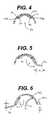
- FIG. 4is a sectional view of the retractor shown in FIG. 1 taken along line 4 - 4 ;
- FIG. 5is a sectional view of the retractor shown in FIG. 2 taken along line 5 - 5 ;
- FIG. 6is a sectional view of the retractor shown in FIG. 3 taken along line 6 - 6 ;
- FIG. 7is a side view of the retractor shown in FIG. 2 ;
- FIG. 8is a side sectional view of the retractor shown in FIG. 1 ;
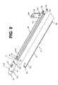
- FIG. 9is an exploded view of the retractor shown in FIG. 1 with the handle omitted for clarity;
- FIG. 10is an exploded view of the retractor shown in FIG. 1 ;
- FIG. 11is a perspective view of a first variation of the retractor of the present invention depicting wireform paddles
- FIG. 12is a bottom plan view of the retractor shown in FIG. 11 with the wireform paddles in the stowed position;
- FIG. 13is a bottom plan view of the retractor shown in FIG. 11 with the wireform paddles in the extended position;
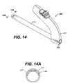
- FIG. 14is a perspective view of a second variation of the retractor of the present invention with the paddles in the stowed position;
- FIG. 14Ais a sectional view of the retractor shown in FIG. 14 taken along line 14 A- 14 A;
- FIG. 15is a perspective view of the retractor shown in FIG. 14 with the paddles in the forward position;
- FIG. 16is a perspective view of the retractor shown in FIG. 14 with the paddles in the extended position;
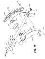
- FIG. 17is an exploded view of the retractor shown in FIG. 14 ;
- FIGS. 18-20are graphic representations of one embodiment of the actuation mechanism for the retractor shown in FIG. 14 .
- the devices of the present inventionare preferably configured as disposable devices, however, the devices can also be configured as semi-reusable or reusable without departing from the scope or spirit of the present invention.
- Retractor 50includes a handle 51 , also serving as, and alternatively referred to as a housing, a shaft 52 extending distally from handle 51 , and a working head 53 attached to the distal end of shaft 52 .
- Retractor 50is typically used with an endoscope attached to or inserted through handle 51 and beneath shaft 52 so that an operator may view into a working space created by working head 53 .
- retractor 50is used in conjunction with a multitool instrument more fully described in related U.S. patent application Ser. No. 10/699,064, filed on the date of this application and assigned to Ethicon, Inc.
- U.S. Pat. No. 5,928,138discloses how devices may be used with other instruments for dissecting and harvesting a vein, the disclosure of which is hereby incorporated by reference.
- retractor 50may include a docking port 90 that releasably mates with a dock 140 of a multitool instrument such that retractor 50 and the multitool instrument can be used together.
- Docking port 90is preferably formed as part of handle 51 .
- handle 51is generally fabricated from a medical grade thermoplastic and is preferably formed in a “clamshell” design having first and second halves 51 a , 51 b . The clamshell design allows for easy assembly of the internal components.
- the halves 51 a , 52 bare fixed together by any means known in the art, such as by a press fit, or with a medical grade epoxy or adhesive, or by ultrasonic welding or by mechanical means, such as by screws, or by any combination of the above.
- shaft 52is fabricated from a medical grade resilient material, such as stainless steel.
- a proximal end 52 a of shaft 52is attached to a member 56 , which extends upwardly from proximal end 52 a .
- Member 56may have openings 56 a , 56 b to facilitate attachment to handle 51 by any means known in the art, such as a press fit or a medical grade epoxy or adhesive or heat-staking.
- openings 56 a and 56 b of member 56are sized to accommodate projections 58 a , 58 b ( FIG.
- a distal end 52 bincludes an opening 55 that is dimensioned to mate with a portion 53 a of the working head 53 .
- Opening 55is preferably formed by removing material from a cross-sectional portion of the shaft 52 . The removal of material to form opening 55 can be done by conventional machining or punching processes known in the art.
- Portion 53 a of working head 53is affixed to shaft 52 by any means known in the art, such as by a press fit and/or with a medical grade epoxy or adhesive.
- Shaft 52is preferably shaped to form channels 52 d and 52 e ( FIG. 3A ) along a portion of the longitudinal length of shaft 52 .
- working head 53tapers to a distal end 54 having a leading edge 54 a so that an operator can easily use working head 53 to separate tissue layers and isolate a vessel from surrounding tissues.
- working head 53may have a notch 54 b in leading edge 54 a to provide for better visualization and management of anterior side branches.
- Working head 53includes an outer surface 53 b that terminates at a peripheral edge 53 c .
- Working space 57is defined as the area between the tissue overlying the blood vessel and the tissue underlying the blood vessel separated by working head 53 .
- Working head 53also includes recesses 53 d and 53 e spaced apart laterally from one another and substantially aligned with channels 52 d and 52 e , respectively, of shaft 52 .
- Working head 53is useful for grossly dissecting tissue away from a vessel, such as the saphenous vein, when introduced through an incision in tissue, and creating a working space to permit the separation of the vessel from the surrounding tissue during EVH.
- Working head 53is preferably made of a medical grade, injection moldable plastic, such as polycarbonate, and is optionally clear for endoscopic viewing of tissue both inside and adjacent to working head 53 .
- working head 53is preferably symmetrically shaped about a medial plane M and is generally concave.
- Working head 53may have a spoon-shaped configuration, or it may consist of a bridge that extends for a portion or the full length of shaft 52 , such as those depicted in U.S. Pat. No.
- working head 53may consist of a tube having a semi-circular or a rhomboidal cross section when viewed axially. Such tubes may be entirely enclosed or have windows created therein.
- working head 53can be any shape that defines a working space 57 that facilitates the introduction of instruments into working space 57 in order to perform various steps of a surgical procedure.
- retractor 50also includes a vessel retractor system for manipulating a vessel proximate working space 57 during EVH by repositioning the vessel within the operating field.
- the vessel retracting systemincludes a first manipulator 60 , a first actuation system 68 ( FIG. 10 ), a second manipulator 70 and a second actuation system 78 .
- retractor 50can include one or more retractors.
- retractor 50includes a first manipulator 60 and a second manipulator 70 , each disposed at least partially within working space 57 .
- First manipulator 60includes a first rod 61 having a proximal end 61 a , a distal end 61 b , a distal portion 61 c , and a first paddle 62 extending from the distal portion 61 c .
- First rod 61is preferably made from stainless steel wire having a diameter approximately in the range of 0.025 inch to 0.075 inches, but most preferably 0.050 inches.
- a portion of rod 61is disposed within channel 52 d of shaft 52 with distal portion 61 b extending beyond distal end 52 b of shaft 52 and within working space 57 .
- Distal end 61 bis disposed within recess 53 d of working head 53 .
- Channel 52 d and recess 53 dare configured to retain a portion of rod 61 , while permitting rod 61 to rotate freely within channel 52 d and recess 53 d .
- First paddle 62is preferably attached to first rod 61 by laser welding, but could be attached by any means known to one skilled in the art.
- second manipulator 70includes a second rod 71 having a proximal end 71 a , a distal end 71 b and a distal portion 71 c , each of which are not shown in the figures, but are similar in form and function to the corresponding elements 61 a , 61 b and 61 c of first manipulator 61 .
- Manipulator 70also includes a second paddle 72 extending from the distal portion 71 c .
- Second rod 71is preferably made from stainless steel wire having a diameter approximately in the range of 0.025 inch to 0.075 inches, but most preferably 0.050 inches.
- a portion of second rod 71is disposed partially within channel 52 e of shaft 52 with distal portion 71 b extending beyond distal end 52 b of shaft 52 and within working space 57 .
- Distal end 71 bis disposed within recess 53 e of working head 53 .
- Channel 52 e and recess 53 eare configured to retain a portion of second rod 71 , while permitting second rod 71 to rotate freely within channel 52 e and recess 53 e .
- Second paddle 72is attached to second rod 71 by laser welding, but could be attached by any means known to one skilled in the art.
- first paddle 62 and second paddle 72are positioned offset distally from one another so as that one paddle does not to interfere with the other paddle's motion.
- first paddle 62extends from first rod 61 at a location distal to the location where second paddle 72 extends from second rod 71 .
- first paddle 62is retained within working head 53 at a location distal in a longitudinal direction to second paddle 72 .
- either paddlecould be configured in this way.
- first rod 61 and second rod 71are offset from one another relative to the medial plane M of working head 53 .
- retractor 50includes first actuation system 68 for moving paddle 62 between the retracted or stowed position and the extended position.
- the retractor 50includes second actuation system 78 for moving paddle 72 between the retracted position and the extended position.
- the first actuation systemis actuated by moving a first actuator 66 movably disposed in handle 52 .
- First actuator 66is preferably slidably disposed in handle 52 and operably connected to first paddle 62 , such that moving first actuator 66 a predetermined distance rotates first paddle 62 between the retracted and extended positions.
- the second actuation systemis actuated by moving a second actuator 76 movably disposed in handle 52 .
- Second actuator 76is preferably slidably disposed in handle 52 and operably connected to second paddle 72 , such that moving second actuator 76 a predetermined distance rotates second paddle 72 between the retracted and extended positions.
- first actuator 66 of first actuation system 68is operably attached to first paddle 62 so as to translate a linear motion to a rotational motion.
- First actuator 66includes a first button 69 that the user moves to generate rotation of first paddle 62 .
- First actuator 66preferably also includes a slide 67 either integral with or separably attached to first button 69 .
- First slide 67is configured to retain one end of a wire 65 and to slidably ride in a slot 82 a formed by lip 51 c of handle 51 and a spacer 80 .
- First wire 65is connected at a distal end to first slide 67 and at a proximal end to a first rack 64 .
- First rack 64is matingly engaged with a first pinion 63 , which is preferably attached on one side to proximal end 61 a of first rod 61 and rotates in a slot formed by backplate 81 and handle half 51 a .
- second actuator 76 of second actuation system 78is operably attached to second paddle 72 so as to translate a linear motion to a rotational motion.
- Second actuator 76includes a second button 79 that the user moves to generate rotation of second paddle 72 .
- Second actuator 76preferably also includes a slide 77 either integral with or separably attached to second button 79 .
- Second slide 77is configured to retain one end of a wire 75 and to slidably ride in a slot 82 b formed by lip 51 d of handle 51 and a spacer 80 .
- Second wire 75is connected at a distal end to second slide 77 and at a proximal end to a second rack 74 .
- Second rack 74is matingly engaged with a second pinion 73 , which is preferably attached on one side to proximal end 71 a of second rod 71 and rotates in a slot formed by backplate 81 and handle half 51 b.
- first and second racks 64 , 74 , first and second pinions 63 , 73 , and backplate 81are all disposed within handle 51 .
- Actuators 66 , 76 , racks 64 , 74 , pinions 63 , 73 and spacer 80are all preferably formed of a medical grade, injection moldable plastic, such as glass-filled nylon.
- Wires 65 and 75are formed of a relatively flexible metal, such as stainless steel, and preferably range from 0.02 to 0.04 inches in diameter, and most preferably, is approximately 0.03 inches in diameter.
- Backplate 81is preferably formed of stamped stainless steel.
- first button 69 and second button 79are shown in their most proximal position, or the position closest to the operator's hand, within slots 82 a and 82 b . In this position, paddles 62 and 72 are retained within working head 53 in their stowed or retracted position.
- displacement of first button 69 distally (or away from the operator's hand), in a direction depicted by arrow A,causes first wire 65 to move upwardly and distally (shown by broken arrow B), which in turn causes the first rack 64 to move upwardly.
- the motion of first rack 64in turn causes first pinion 63 to rotate in the clockwise direction depicted as arrow C.
- first pinion 63As pinion 63 is attached to rod 61 , rotation of first pinion 63 causes first paddle 62 to also rotate in the clockwise direction.
- moving second button 79 distally in a direction depicted by arrow Dcauses second wire 75 to move upwardly and distally, which in turn causes second rack 74 to move upwardly, causing second pinion 73 and second paddle 72 to rotate in a counter-clockwise direction shown by arrow E.
- First button 69 and second button 79are positioned side by side such that a user that grasps retractor 50 with one hand, may actuate either or both buttons by using a thumb or finger.
- the usercan manually retract tissue to form working space 57 and retract the vessel being harvested by using retractor 50 , without the need for a separate instrument.
- retractor 50includes first paddle 62 on one side of the medial line of retractor 50 and second paddle 72 on the other side of the medial line of retractor 50 , the user may move the vessel to one side away from the medial line of retractor 50 using first paddle 62 or the other side away from the medial line of retractor 50 using second paddle 72 , without the need to reposition or rotate retractor 50 .
- the usercan use first paddle 62 to manipulate the vessel away from the side branch, and, similarly, where the user would like to transect a side branch on the left side of vessel, the user can use second paddle 72 to manipulate the vessel away from the side branch.
- first retractor and second retractorcould be actuated using one actuation system.
- first retractor and second retractorcould be actuated using one actuation system.
- a single buttoncan be toggled left or right to engage slide 67 or slide 77 depending upon which manipulator the user wanted to actuate.
- the remainder of the actuation mechanismwould work similarly to the described device; i.e., slides 67 , 77 could move wires 65 , 75 and racks 64 , 74 to act upon pinions 63 , 73 and manipulators 60 , 70 .
- first paddle 62 and second paddle 72are shown in their stowed or retracted position.
- First paddle 62 and second paddle 72are positioned to nest longitudinally in a side-by-side configuration close to a portion of the interior surface 53 f of working head 53 .
- first paddle 62 and second paddle 72are preferably shaped to substantially minimize the amount of working space obstructed by the paddles themselves.
- first paddle 62may rotate about the pivot point defined in recess 53 d through an arc F of approximately 100 to 140 degrees, but most preferably 120 degrees.
- second paddle 72may rotate about the pivot point defined in recess 53 e through an arc G of approximately 100 to 140 degrees, but most preferably 120 degrees. In each case, however, it is contemplated that the angle of rotation could be greater or smaller depending upon the location of recesses 53 d , 53 e and the curvature of working head 53 .
- first paddle 62extends below peripheral edge 53 c when first paddle 62 is in the extended position.
- first paddle 62has a curved portion that forms a concave surface that faces away from working head 53 when in the extended position.
- paddles 62 and 72when in the fully extended position, extend a distance X of approximately 0.10 inches to 0.25 inches medially outwardly ( FIG. 5 ) from working head 53 , but most preferably approximately 0.15 inches, and downwardly ( FIG. 6 ) from working head 53 a distance Y of approximately 0.15 inches to 0.35 inches, but most preferably approximately 0.20 inches.
- the tip of paddle 62 , 72( FIG. 6 ) preferably extends a distance Z of approximately 0.15 inches to 0.35 inches below edge 52 c , but most preferably approximately 0.25 inches.
- the length of the paddlesis preferably configured to be long enough to manipulate a vessel to a position that does not interfere with the working space, but short enough so as not to be prevented from rotating by the layer of tissue at the bottom of the working space when the paddles are actuated.
- FIGS. 11-13show a second variation of first and second manipulators of the present invention, depicted as first manipulator 160 and second manipulator 170 .
- FIG. 11is a perspective view and FIGS. 12 and 13 are bottom plan views showing first manipulator 160 that includes a first mating paddle 162 fixed to rod 61 , and second manipulator 170 that includes a second mating paddle 172 fixed to rod 71 .
- mating paddle 162preferably includes fingers 163 , configured to mate or interlace with fingers 173 of mating paddle 172 when in the stowed position.
- Mating paddles 162 , 172may be formed of wire as shown in the figures or may be a solid material, such as plastic or stainless steel.
- Mating paddles 162 , 172are shown as having three fingers 163 , 173 , but the paddles may have two or more fingers that mate with one another when in the stowed position. Further, the shape of the fingers may differ considerably from what is shown, so long as the first paddle has at least two portions connected by an intermediate portion such that a space between the at least two portions mates with a portion of the second paddle. For example, referring to FIG. 13 , first paddle 162 includes a first portion 164 and a second portion 165 connected by an intermediate portion 166 such that a space 167 is created between first and second portions 165 and 166 .
- Second paddle 172includes at least one portion 174 configured to mate with first paddle 162 such that portion 174 occupies space 167 when paddles 162 , 172 are in the stowed position. As is shown in FIG. 11 , the paddles 162 and 172 may be actuated similarly to paddles 62 and 72 of the first embodiment, by moving buttons 169 , 179 distally to rotate paddle 162 and 172 , respectively.
- FIG. 7is a side view of retractor 50 being used in a surgical procedure in combination with a multitool instrument (not shown) for endoscopically harvesting a vessel 5 for use in a coronary artery bypass graft (CABG) surgical procedure.
- the multitool instrument and its method of useare disclosed in co-pending U.S. patent application Ser. No. 10/699,063, filed on even date herewith, and are hereby incorporated by reference.
- Multitool instrumentcomprises a cannula having a dock disposed thereon, which may be inserted into docking port 90 of retractor 50 .
- Multitool instrumentalso includes an endoscope for visualizing the tissues within working space 57 .
- a physician or physician's assistantdetermines the location of a vessel to be dissected, and makes an incision in the patient. The user then inserts retractor 50 into the incision and bluntly dissects the tissue surrounding vessel using working head 53 . If the intention is to extract vessel 5 , it is preferable to dissect as much tissue from around the vessel as possible.
- the usermanipulates retractor 50 to advance working head 53 along vessel 5 , separating tissue from vessel 5 and providing a working space for accessing and visualizing vessel 5 and a plurality of side branches, one of which is shown as reference numeral 6 .
- multitool instrumentmay be located above vessel 5 , when docked with retractor 50 , or may be positioned below shaft 52 of retractor 50 in an undocked configuration.
- the usermanipulates either paddle 62 and/or 72 of retractor 50 to position vessel 5 away from the multitool instrument permitting the user to dissect, clamp, coagulate, and cut tissue within working space 57 .
- the usercan manipulate vessel 5 using, for example paddle 62 of retractor 50 such that vessel 5 is protected.
- a surgical tool introduced via the multitool instrumentor through cannula 252 ) can cauterize and cut side branch 6 without damaging vessel 5 .
- the harvesting procedurecontinues in this manner until the vessel is hemostatically isolated from the surrounding tissues and blood supply along the portion to be harvested.
- retractor 50can be withdrawn through the incision. Vessel 5 can then be removed from its native location and prepared for use in a coronary bypass procedure, for example.
- paddles 62 , 72can operate in tandem or can be manipulated such that they work independently of one another.
- paddle 62can be extended independently of paddle 72 as it is positioned distally to paddle 72 .
- Paddle 72may also bypass paddle 62 by first extending each paddle to a position forward of the distal end of cannula 52 , rotating paddle 72 such that it does not interfere with paddle 62 , and then retracting paddle 62 into the stowed position within cannula 52 .
- Retractor 50is especially suited for vessel harvesting, but are not limited to this surgical procedure.
- Retractor 50may be used to retract many different types of tissue, and, similarly, multitool instrument 100 may be used to dissect, clamp, coagulate, and cut tissues during other types of endoscopic and open surgical procedures.
- the instrumentscan also be used to remove other discrete tissues, such as tumors, to ligate fallopian tubes for fertility control, to ligate and transect bile ducts for nephrectomy, or to transect ligaments or other tissue structures.
- FIGS. 14-20a second embodiment of the invention is depicted.
- the manipulation systemis housed in a cannula that creates working space via insufflation rather than by using mechanical retraction as with the first embodiment.
- FIG. 14depicts an instrument 250 that includes a cannula 252 and a handle 251 extending from the proximal end of cannula 252 .
- Handle 251has a throughhole 253 that permits communication with an insufflation source (not shown) and also permits an endoscope and other instruments (not shown) to be passed therethrough.
- Instrument 250 of the present inventionprovides benefits when dissecting vessels from tissue in a patient, however, such a use is given by way of example only and does not limit the scope or spirit of the present invention.
- instrument 250includes a vessel manipulator system for manipulating a vessel during EVH by repositioning the vessel within the operating field.
- instrument 250includes a first manipulator 260 and a second manipulator 270 , each disposed at least partially within cannula 252 .
- first manipulator 260includes a first rod 261 having a first paddle 262 extending from the distal end of first rod 261 .
- second manipulator 270includes a second rod 271 having a second paddle 272 extending from the distal end of second rod 271 .
- First and second rod 261 , 271are preferably made from stainless steel wire having a diameter approximately in the range of 0.025 inch to 0.075 inches, but most preferably 0.050 inches. While first and second manipulators 260 , 270 are depicted as similar to manipulators 60 and 70 of FIGS. 1-10 , manipulators 160 and 170 of FIGS. 11-13 can also be used in connection with this embodiment.
- Instrument 250includes a first actuation system 268 having a first actuator 266 operably attached to first paddle 262 .
- First actuator 266includes a button that the user moves to generate rotation of first paddle 262 .
- First actuator 266preferably also includes a slide 267 either integral with or separably attached to first actuator 266 .
- First slide 267is configured to retain one end of a wire 265 and to slidably ride in a slot 282 a formed by lip 259 a of handle 251 and a spacer 280 .
- First wire 265is connected at a distal end to first slide 267 and at a proximal end to a first rack 264 .
- First rack 264in turn is matingly engaged with a first pinion 263 through window 252 b of cannula 252 .
- the first actuation systemalso includes a first slide actuator 269 for moving first rod 261 axially in and out of cannula 252 .
- Slide actuator 269rides in slot 251 a of handle 251 and slot 252 a of cannula 252 . Slots 251 a and 252 a communicate along their length.
- Slide actuator 269is attached to first rod 261 at a proximal end 261 a .
- First rod 261is preferably snap-fitted to slide actuator 269 at a narrowed section 261 b .
- First rod 261is attached at proximal end 261 a to first pinion 263 .
- Pinion 263is preferably of a length that mates with rack 264 at each of the stowed, forward and extended positions.
- instrument 250includes a second actuation system 278 having a second actuator 276 operably attached to second paddle 272 .
- Second actuator 276includes a button that the user moves to generate rotation of second paddle 272 .
- Second actuator 276preferably also includes a slide 277 either integral with or separably attached to second actuator 276 .
- Second slide 277is configured to retain one end of a wire 275 and to slidably ride in a slot 282 b formed by lip 259 b of handle 251 and spacer 280 .
- Second wire 275is connected at a distal end to second slide 277 and at a proximal end to a second rack 274 .
- Second rack 274is matingly engaged with a second pinion 273 through window 252 d of cannula 252 .
- the second actuation systemalso includes a second slide actuator 279 for moving second rod 271 axially in and out of cannula 252 .
- Slide actuator 279rides in slot 251 b of handle 251 and slot 252 c of cannula 252 .
- Slots 251 b and 252 ccommunicate along their length.
- Slide actuator 279is attached to second rod 271 at a proximal end 271 a .
- Second rod 271is preferably snap-fitted to slide actuator 279 at a narrowed section 271 b .
- Second rod 271is attached at proximal end 271 a to first pinion 273 .
- Cannula 252includes a spacer 290 disposed within or formed as a part of cannula 252 .
- Spacer 290has throughholes 291 and 292 sized to accommodate rods 261 , 271 respectively, such that rods 261 , 271 are slidable within throughholes 291 , 292 .
- first actuator 266 and second actuator 276are shown in their most proximal position, or the position closest to the operator's hand, within slots 282 a and 282 b . In this position, paddles 262 and 272 are retained within cannula 252 in their stowed position.
- the userpositions cannula 252 within an operative space formed by an insufflation fluid passed through cannula 252 or by some other means.
- cannula 252can include a slidable beam (not shown) that moves from a position substantially disposed within cannula 252 to a position distal to the distal end of cannula 252 to create an operative space mechanically. In this way, an insufflation fluid is not necessary.
- first slide actuator 269displacement of first slide actuator 269 in the distal axial direction indicated by arrow H, causes first paddle 262 to be displaced a similar distance such that paddle 262 extends out the distal end of cannula 252 to the forward position.
- second slide actuator 279when second slide actuator 279 is extended in the axial direction, second paddle 272 is also extended from the stowed position to the forward position.
- first actuator 266when first actuator 266 is moved distally (or away from the operator's hand), in a direction depicted by arrow I, first wire 265 moves upwardly and distally, which in turn causes first rack 264 to move upwardly.
- first rack 264causes first pinion 263 to rotate in the clockwise direction depicted as arrow J.
- rotation of first pinion 263causes first paddle 262 to also rotate in the clockwise direction.
- moving second button 79 distally in a direction depicted by arrow Kcauses second wire 275 to move upwardly and distally, which in turn causes second rack 274 to move upwardly, causing second pinion 273 and second paddle 272 to rotate in a counter-clockwise direction shown by arrow L.
- first slide actuator 269The location of first slide actuator 269 and the relative positions of rack 264 and pinion 263 are shown in FIGS. 18-20 graphically.
- slide actuator 269In the stowed position, slide actuator 269 is at a proximal position and paddle 262 is disposed within cannula 252 .
- paddle 262Upon moving slide actuator axially, in a direction H, paddle 262 moves in the axial direction.
- rack 246is pulled in direction I, causing pinion 263 and paddle 262 to rotate in the clockwise direction J.
- handle 51is depicted as an L-shaped handle, the handle could be an in-line handle, which is well-known in the art. It is therefore intended that the invention be not limited to the exact forms described and illustrated, but should be constructed to cover all modifications that may fall within the scope of the appended claims.
Landscapes
- Health & Medical Sciences (AREA)
- Surgery (AREA)
- Life Sciences & Earth Sciences (AREA)
- Medical Informatics (AREA)
- Animal Behavior & Ethology (AREA)
- Engineering & Computer Science (AREA)
- Biomedical Technology (AREA)
- Heart & Thoracic Surgery (AREA)
- Veterinary Medicine (AREA)
- Molecular Biology (AREA)
- Nuclear Medicine, Radiotherapy & Molecular Imaging (AREA)
- General Health & Medical Sciences (AREA)
- Public Health (AREA)
- Ophthalmology & Optometry (AREA)
- Orthopedic Medicine & Surgery (AREA)
- Vascular Medicine (AREA)
- Surgical Instruments (AREA)
Abstract
Description
Claims (6)
Priority Applications (2)
| Application Number | Priority Date | Filing Date | Title |
|---|---|---|---|
| US10/699,337US7314479B2 (en) | 2003-10-31 | 2003-10-31 | Space-creating retractor with vessel manipulator |
| PCT/US2004/035776WO2005045378A2 (en) | 2003-10-31 | 2004-10-26 | Space-creating retractor with vessel manipulator |
Applications Claiming Priority (1)
| Application Number | Priority Date | Filing Date | Title |
|---|---|---|---|
| US10/699,337US7314479B2 (en) | 2003-10-31 | 2003-10-31 | Space-creating retractor with vessel manipulator |
Publications (2)
| Publication Number | Publication Date |
|---|---|
| US20050096677A1 US20050096677A1 (en) | 2005-05-05 |
| US7314479B2true US7314479B2 (en) | 2008-01-01 |
Family
ID=34550934
Family Applications (1)
| Application Number | Title | Priority Date | Filing Date |
|---|---|---|---|
| US10/699,337Expired - Fee RelatedUS7314479B2 (en) | 2003-10-31 | 2003-10-31 | Space-creating retractor with vessel manipulator |
Country Status (1)
| Country | Link |
|---|---|
| US (1) | US7314479B2 (en) |
Cited By (9)
| Publication number | Priority date | Publication date | Assignee | Title |
|---|---|---|---|---|
| US20050203345A1 (en)* | 2005-03-03 | 2005-09-15 | Ken Yamaguchi | Articulating paddle elevator and arthroscopic method for using same |
| US20070021655A1 (en)* | 2005-07-15 | 2007-01-25 | Dr. Ayoub Sayeg | Method and instruments for breast augmentation mammaplasty |
| US20080255600A1 (en)* | 2005-02-10 | 2008-10-16 | Medical Device Innovations Ltd. | Endoscopic Dissector |
| USD581050S1 (en)* | 2006-03-10 | 2008-11-18 | Medical Device Innovations Limited | Surgical instrument tip |
| USD622380S1 (en)* | 2006-03-10 | 2010-08-24 | Medical Device Innovations Limited | Surgical instrument |
| USD623739S1 (en)* | 2006-03-10 | 2010-09-14 | Medical Device Innovations Limited | Surgical instrument handle |
| USD660422S1 (en)* | 2010-12-23 | 2012-05-22 | Karl Storz Gmbh & Co. Kg | Spate for thyroid surgery |
| US20120239086A1 (en)* | 2011-03-14 | 2012-09-20 | Reznik Alan M | Nonlinear self seating suture anchor for confined spaces |
| US20170245845A1 (en)* | 2016-02-29 | 2017-08-31 | Terumo Kabushiki Kaisha | Dissecting device |
Families Citing this family (6)
| Publication number | Priority date | Publication date | Assignee | Title |
|---|---|---|---|---|
| US7367983B2 (en) | 2005-09-15 | 2008-05-06 | Dziadik Stephen P | Vessel harvesting apparatus |
| EP3165247B1 (en) | 2006-02-09 | 2020-10-28 | DEKA Products Limited Partnership | Pumping fluid delivery systems and methods using force application assembley |
| US8992424B2 (en)* | 2007-02-09 | 2015-03-31 | Skeletal Dynamics Llc | Endo-surgical device and method |
| US8623046B2 (en)* | 2007-08-10 | 2014-01-07 | Donald Lee Sturtevant | Treatment for patients after removal of saphenous vascular material |
| JP5203134B2 (en)* | 2008-10-27 | 2013-06-05 | 株式会社大一器械 | Raising aid |
| US20120289947A1 (en)* | 2010-01-18 | 2012-11-15 | Wolfgang Neuberger | Device and method for removing veins |
Citations (129)
| Publication number | Priority date | Publication date | Assignee | Title |
|---|---|---|---|---|
| US2002594A (en) | 1933-03-24 | 1935-05-28 | Wappler Frederick Charles | Instrument for electro-surgical treatment of tissue |
| US2055188A (en) | 1934-04-09 | 1936-09-22 | American Cystoscope Makers Inc | Fluoroscope |
| US3799150A (en) | 1970-12-05 | 1974-03-26 | L Bonnet | Endoscopes |
| US3844272A (en) | 1969-02-14 | 1974-10-29 | A Banko | Surgical instruments |
| US4052980A (en) | 1976-06-10 | 1977-10-11 | Guenter A. Grams | Triaxial fiberoptic soft tissue retractor |
| US4391282A (en) | 1979-10-24 | 1983-07-05 | Olympus Optical Company Limited | Coeliac cavity ultrasonic diagnosis apparatus |
| US4573451A (en) | 1984-11-08 | 1986-03-04 | Jack Bauman | Laryngoscope blade with a bendable tip |
| US4605009A (en) | 1983-04-06 | 1986-08-12 | Universite Francois Rabelais | Ultrasonic sweep echography and display endoscopic probe |
| US5013312A (en) | 1990-03-19 | 1991-05-07 | Everest Medical Corporation | Bipolar scalpel for harvesting internal mammary artery |
| US5085659A (en) | 1990-11-21 | 1992-02-04 | Everest Medical Corporation | Biopsy device with bipolar coagulation capability |
| US5171255A (en) | 1990-11-21 | 1992-12-15 | Everest Medical Corporation | Biopsy device |
| US5324289A (en) | 1991-06-07 | 1994-06-28 | Hemostatic Surgery Corporation | Hemostatic bi-polar electrosurgical cutting apparatus and methods of use |
| USD349341S (en) | 1992-10-28 | 1994-08-02 | Microsurge, Inc. | Endoscopic grasper |
| USD350606S (en) | 1992-03-16 | 1994-09-13 | Tibor Koros | Combined laparoscopic grasper and cutter |
| US5373840A (en) | 1992-10-02 | 1994-12-20 | Knighton; David R. | Endoscope and method for vein removal |
| US5403312A (en) | 1993-07-22 | 1995-04-04 | Ethicon, Inc. | Electrosurgical hemostatic device |
| US5443463A (en) | 1992-05-01 | 1995-08-22 | Vesta Medical, Inc. | Coagulating forceps |
| US5445638A (en) | 1993-03-08 | 1995-08-29 | Everest Medical Corporation | Bipolar coagulation and cutting forceps |
| US5458598A (en) | 1993-12-02 | 1995-10-17 | Cabot Technology Corporation | Cutting and coagulating forceps |
| US5462546A (en) | 1993-02-05 | 1995-10-31 | Everest Medical Corporation | Bipolar electrosurgical forceps |
| US5484436A (en) | 1991-06-07 | 1996-01-16 | Hemostatic Surgery Corporation | Bi-polar electrosurgical instruments and methods of making |
| US5512037A (en) | 1994-05-12 | 1996-04-30 | United States Surgical Corporation | Percutaneous surgical retractor |
| US5514148A (en) | 1994-11-04 | 1996-05-07 | Smith, Iii; Ray C. | Surgical clamp and method of use |
| US5527313A (en) | 1992-09-23 | 1996-06-18 | United States Surgical Corporation | Bipolar surgical instruments |
| US5531744A (en) | 1991-11-01 | 1996-07-02 | Medical Scientific, Inc. | Alternative current pathways for bipolar surgical cutting tool |
| US5536234A (en) | 1993-08-18 | 1996-07-16 | Vista Medical Technologies, Inc. | Optical surgical device with scraping tool |
| US5569274A (en) | 1993-02-22 | 1996-10-29 | Heartport, Inc. | Endoscopic vascular clamping system and method |
| US5573534A (en) | 1993-05-06 | 1996-11-12 | United States Surgical Corporation | Bipolar electrosurgical instruments |
| US5573535A (en) | 1994-09-23 | 1996-11-12 | United States Surgical Corporation | Bipolar surgical instrument for coagulation and cutting |
| US5591183A (en) | 1995-04-12 | 1997-01-07 | Origin Medsystems, Inc. | Dissection apparatus |
| US5593418A (en) | 1995-05-19 | 1997-01-14 | General Surgical Innovations, Inc. | Methods and devices for harvesting blood vessels with balloons |
| US5601581A (en) | 1995-05-19 | 1997-02-11 | General Surgical Innovations, Inc. | Methods and devices for blood vessel harvesting |
| US5647838A (en) | 1994-05-10 | 1997-07-15 | Bloomer; William E. | Camera fixture for stereoscopic imagery and method of using same |
| US5658282A (en) | 1994-01-18 | 1997-08-19 | Endovascular, Inc. | Apparatus for in situ saphenous vein bypass and less-invasive varicose vein treatment |
| US5665100A (en) | 1989-12-05 | 1997-09-09 | Yoon; Inbae | Multifunctional instrument with interchangeable operating units for performing endoscopic procedures |
| US5665085A (en) | 1991-11-01 | 1997-09-09 | Medical Scientific, Inc. | Electrosurgical cutting tool |
| US5667480A (en) | 1995-10-20 | 1997-09-16 | Ethicon Endo-Surgery, Inc. | Method and devices for endoscopic vessel harvesting |
| US5685824A (en) | 1994-10-11 | 1997-11-11 | Astem Tech Company, Limited | Prostascope with a bridge |
| US5695514A (en) | 1995-07-13 | 1997-12-09 | Guidant Corporation | Method and apparatus for harvesting blood vessels |
| US5709224A (en) | 1995-06-07 | 1998-01-20 | Radiotherapeutics Corporation | Method and device for permanent vessel occlusion |
| US5709680A (en) | 1993-07-22 | 1998-01-20 | Ethicon Endo-Surgery, Inc. | Electrosurgical hemostatic device |
| US5713896A (en) | 1991-11-01 | 1998-02-03 | Medical Scientific, Inc. | Impedance feedback electrosurgical system |
| US5749830A (en) | 1993-12-03 | 1998-05-12 | Olympus Optical Co., Ltd. | Fluorescent endoscope apparatus |
| US5759150A (en) | 1995-07-07 | 1998-06-02 | Olympus Optical Co., Ltd. | System for evulsing subcutaneous tissue |
| US5766166A (en) | 1995-03-07 | 1998-06-16 | Enable Medical Corporation | Bipolar Electrosurgical scissors |
| US5772576A (en) | 1995-12-11 | 1998-06-30 | Embro Vascular L.L.C. | Apparatus and method for vein removal |
| US5792139A (en) | 1993-12-02 | 1998-08-11 | Ethicon Endo-Surgery, Inc. | Electrosurgical instrument with interchangeable surgical tools |
| US5797941A (en) | 1995-02-01 | 1998-08-25 | Ethicon Endo-Surgery, Inc. | Surgical instrument with expandable cutting element |
| US5797938A (en) | 1995-10-20 | 1998-08-25 | Ethicon Endo-Surgery, Inc. | Self protecting knife for curved jaw surgical instruments |
| US5800449A (en) | 1997-03-11 | 1998-09-01 | Ethicon Endo-Surgery, Inc. | Knife shield for surgical instruments |
| US5810128A (en) | 1995-05-18 | 1998-09-22 | Yamaha Hatsudoki Kabushiki Kaisha | Shock absorber |
| US5817013A (en) | 1996-03-19 | 1998-10-06 | Enable Medical Corporation | Method and apparatus for the minimally invasive harvesting of a saphenous vein and the like |
| US5826776A (en) | 1994-12-19 | 1998-10-27 | Ethicon Endo-Surgery, Inc. | Surgical instrument |
| US5827279A (en) | 1996-12-06 | 1998-10-27 | Ethicon Endo-Surgery, Inc. | Knife coupler mechanism for an endoscopic instrument |
| US5827176A (en) | 1996-02-13 | 1998-10-27 | Fuji Photo Optical Co., Ltd. | Endoscopic imaging system with rotating photoelectric line sensor |
| US5836945A (en) | 1997-02-20 | 1998-11-17 | Perkins; Rodney C. | Biological vessel harvesting device |
| US5846185A (en) | 1996-09-17 | 1998-12-08 | Carollo; Jerome T. | High resolution, wide field of view endoscopic viewing system |
| US5860975A (en) | 1994-12-21 | 1999-01-19 | Gyrus Medical Limited | Electrosurgical instrument |
| US5865726A (en) | 1996-03-27 | 1999-02-02 | Asahi Kogaku Kogyo Kabushiki Kaisha | Front end structure of side-view type endoscope |
| US5873889A (en) | 1997-08-08 | 1999-02-23 | Origin Medsystems, Inc. | Tissue separation cannula with dissection probe and method |
| WO1999012487A1 (en) | 1997-09-09 | 1999-03-18 | Sherwood Services Ag | Apparatus and method for sealing and cutting tissue |
| US5891141A (en) | 1997-09-02 | 1999-04-06 | Everest Medical Corporation | Bipolar electrosurgical instrument for cutting and sealing tubular tissue structures |
| US5891140A (en) | 1996-12-23 | 1999-04-06 | Cardiothoracic Systems, Inc. | Electrosurgical device for harvesting a vessel especially the internal mammary artery for coronary artery bypass grafting |
| US5895353A (en) | 1998-06-22 | 1999-04-20 | Origin Medsystems, Inc. | Vessel isolating retractor cannula and method |
| US5902315A (en) | 1997-08-28 | 1999-05-11 | Ethicon Endo-Surgery, Inc. | Optical tissue dissector/retractor |
| US5913818A (en) | 1997-06-02 | 1999-06-22 | General Surgical Innovations, Inc. | Vascular retractor |
| US5913866A (en) | 1997-06-19 | 1999-06-22 | Cardiothoracic Systems, Inc. | Devices and methods for harvesting vascular conduits |
| US5916233A (en) | 1998-03-05 | 1999-06-29 | Origin Medsystems, Inc. | Vessel harvesting method and instrument including access port |
| US5921984A (en) | 1994-11-30 | 1999-07-13 | Conmed Corporation | Bipolar electrosurgical instrument with coagulation feature |
| US5922001A (en) | 1989-12-05 | 1999-07-13 | Yoon; Inbae | Surgical instrument with jaws and a movable internal blade member and method for use thereof |
| US5922004A (en) | 1997-08-28 | 1999-07-13 | Ethicon Endo-Surgery, Inc. | Method for performing optical tissue dissection/retraction |
| US5921919A (en) | 1997-05-30 | 1999-07-13 | Origin Medsystems, Inc. | Perivascular self-retaining retractor and method |
| US5921916A (en) | 1994-07-07 | 1999-07-13 | Ueth & Haug Gmbh | Endoscope utilizing a fiber optic holding tube with a jacket slit for lateral placement of the fiber optic |
| US5925045A (en) | 1993-11-10 | 1999-07-20 | Mentor Corporation | Bipolar electrosurgical instrument |
| US5928138A (en) | 1996-08-15 | 1999-07-27 | Ethicon Endo-Surgery, Inc. | Method and devices for endoscopic vessel harvesting |
| US5938680A (en) | 1997-06-19 | 1999-08-17 | Cardiothoracic Systems, Inc. | Devices and methods for harvesting vascular conduits |
| US5951549A (en) | 1996-12-20 | 1999-09-14 | Enable Medical Corporation | Bipolar electrosurgical scissors |
| US5954720A (en) | 1996-10-28 | 1999-09-21 | Endoscopic Concepts, Inc. | Bipolar electrosurgical end effectors |
| USD415146S (en) | 1997-11-12 | 1999-10-12 | Vista Medical Technologies, Inc. | Head mounted display |
| US5968065A (en) | 1995-07-13 | 1999-10-19 | Origin Medsystems, Inc. | Tissue separation cannula |
| US5968066A (en) | 1994-06-29 | 1999-10-19 | General Surgical Innovations, Inc. | Methods and devices for blood vessel harvesting |
| US5970982A (en) | 1997-02-20 | 1999-10-26 | Perkins; Rodney C. | Minimally invasive biological vessel harvesting method |
| US5972010A (en) | 1998-05-14 | 1999-10-26 | Taheri; Syde A. | Vein harvesting system |
| US5976168A (en) | 1995-07-13 | 1999-11-02 | Origin Medsystems, Inc. | Tissue separation cannula |
| US5984937A (en) | 1997-03-31 | 1999-11-16 | Origin Medsystems, Inc. | Orbital dissection cannula and method |
| WO1999066842A1 (en) | 1998-06-19 | 1999-12-29 | Karl Storz Gmbh & Co. | Medical instrument for endoscopic removal of the vena saphena magna |
| WO1999066850A1 (en) | 1998-06-22 | 1999-12-29 | Lina Medical Aps | An electrosurgical device for coagulating and for making incisions, a method of severing blood vessels and a method of coagulating and for making incisions in or severing tissue |
| US6017358A (en)* | 1997-05-01 | 2000-01-25 | Inbae Yoon | Surgical instrument with multiple rotatably mounted offset end effectors |
| US6019771A (en) | 1996-12-02 | 2000-02-01 | Cardiothoracic Systems, Inc. | Devices and methods for minimally invasive harvesting of a vessel especially the saphenous vein for coronary bypass grafting |
| US6024741A (en) | 1993-07-22 | 2000-02-15 | Ethicon Endo-Surgery, Inc. | Surgical tissue treating device with locking mechanism |
| EP0979635A2 (en) | 1998-08-12 | 2000-02-16 | Origin Medsystems, Inc. | Tissue dissector apparatus |
| US6030384A (en) | 1998-05-01 | 2000-02-29 | Nezhat; Camran | Bipolar surgical instruments having focused electrical fields |
| US6036713A (en) | 1996-01-24 | 2000-03-14 | Archimedes Surgical, Inc. | Instruments and methods for minimally invasive vascular procedures |
| US6039733A (en) | 1995-09-19 | 2000-03-21 | Valleylab, Inc. | Method of vascular tissue sealing pressure control |
| US6042538A (en) | 1998-11-18 | 2000-03-28 | Emory University | Device for endoscopic vessel harvesting |
| US6056746A (en) | 1995-06-23 | 2000-05-02 | Gyrus Medical Limited | Electrosurgical instrument |
| US6059802A (en) | 1998-02-27 | 2000-05-09 | Cardiothoracic Systems, Inc. | Dissecting retractor for harvesting vessels |
| US6059782A (en) | 1995-11-20 | 2000-05-09 | Storz Endoskop Gmbh | Bipolar high-frequency surgical instrument |
| US6066137A (en) | 1997-10-03 | 2000-05-23 | Megadyne Medical Products, Inc. | Electric field concentrated electrosurgical electrode |
| WO2000015116A9 (en) | 1998-09-10 | 2000-06-22 | Gen Surgical Innovations Inc | Direct vision subcutaneous tissue retractor |
| US6083223A (en) | 1997-08-28 | 2000-07-04 | Baker; James A. | Methods and apparatus for welding blood vessels |
| US6086586A (en) | 1998-09-14 | 2000-07-11 | Enable Medical Corporation | Bipolar tissue grasping apparatus and tissue welding method |
| US6110170A (en) | 1996-03-20 | 2000-08-29 | Cardiothoracic Systems, Inc. | Surgical instrument for facilitating the detachment of an artery and the like |
| US6113395A (en) | 1998-08-18 | 2000-09-05 | Hon; David C. | Selectable instruments with homing devices for haptic virtual reality medical simulation |
| US6113598A (en) | 1998-02-17 | 2000-09-05 | Baker; James A. | Radiofrequency medical instrument and methods for vessel welding |
| US6120433A (en) | 1994-09-01 | 2000-09-19 | Olympus Optical Co., Ltd. | Surgical manipulator system |
| US6120434A (en) | 1994-08-29 | 2000-09-19 | Olympus Optical Co., Ltd. | Method of securing a cavity using a rigid sheath with transparent cap |
| US6126658A (en) | 1998-02-19 | 2000-10-03 | Baker; James A. | Radiofrequency medical instrument and methods for vessel welding |
| US6129661A (en) | 1998-04-09 | 2000-10-10 | Smith & Nephew, Inc. | Endoscopic instrumentation with working channel |
| US6135999A (en) | 1997-02-12 | 2000-10-24 | Oratec Internationals, Inc. | Concave probe for arthroscopic surgery |
| US6139489A (en) | 1999-10-05 | 2000-10-31 | Ethicon Endo-Surgery, Inc. | Surgical device with integrally mounted image sensor |
| US6162173A (en) | 1998-06-22 | 2000-12-19 | Origin Medsystems, Inc. | Device and method for remote vessel ligation |
| US6206823B1 (en) | 1999-08-02 | 2001-03-27 | Ethicon Endo-Surgery, Inc. | Surgical instrument and method for endoscopic tissue dissection |
| US6306345B1 (en) | 1998-05-06 | 2001-10-23 | Universal Preservation Technologies, Inc. | Industrial scale barrier technology for preservation of sensitive biological materials at ambient temperatures |
| US6306082B1 (en) | 1994-03-17 | 2001-10-23 | Olympus Optical Co. | Stereoendoscope wherein images having passed through plural incident pupils are transmitted by common relay optical systems |
| US6309345B1 (en) | 1997-08-21 | 2001-10-30 | Paul Stelzer | Minimally invasive surgery device |
| US6334860B1 (en) | 1998-12-18 | 2002-01-01 | Karl Storz Gmbh & Co. Kg | Bipolar medical instrument |
| US6464702B2 (en) | 2001-01-24 | 2002-10-15 | Ethicon, Inc. | Electrosurgical instrument with closing tube for conducting RF energy and moving jaws |
| US20030032864A1 (en) | 2000-03-06 | 2003-02-13 | Friesen John H.P. | Laryngoscope |
| US6527771B1 (en) | 2001-09-28 | 2003-03-04 | Ethicon, Inc. | Surgical device for endoscopic vein harvesting |
| US20030065351A1 (en) | 2001-09-28 | 2003-04-03 | Hess Christopher J. | Vessel harvesting retractor with dissection element |
| US20030065349A1 (en) | 2001-09-28 | 2003-04-03 | Hess Christopher J. | Vessel harvesting retractor with bilateral electrosurgical ligation |
| US20030065323A1 (en) | 2001-09-28 | 2003-04-03 | Hess Christopher J. | Vessel harvesing retractor with electrosurgical plunger |
| US20030065348A1 (en) | 2001-09-28 | 2003-04-03 | Hess Christopher J. | Vessel harvesting retractor with integral electrosurgical clamping elements |
| US20030130674A1 (en) | 2001-12-27 | 2003-07-10 | Olympus Optical Co., Ltd. And Terumo Kabushiki Kaisha | Treatment sheath for endoscopic blood vessel harvesting |
| US6592482B2 (en) | 2001-10-22 | 2003-07-15 | The Gates Corporation | Tensioner |
| US6616661B2 (en) | 2001-09-28 | 2003-09-09 | Ethicon, Inc. | Surgical device for clamping, ligating, and severing tissue |
| US6623482B2 (en) | 2001-01-24 | 2003-09-23 | Ethicon, Inc. | Electrosurgical instrument with minimally invasive jaws |
| US8456684B2 (en) | 2007-10-10 | 2013-06-04 | Canon Kabushiki Kaisha | Image processing apparatus and method |
Family Cites Families (14)
| Publication number | Priority date | Publication date | Assignee | Title |
|---|---|---|---|---|
| US5023312A (en)* | 1988-07-19 | 1991-06-11 | Erickson Frank L | Meadowfoam oil and meadowfoam oil derivatives as lubricant additives |
| US6206623B1 (en)* | 1995-12-22 | 2001-03-27 | Stephen D. Podd | Bulkhead for retaining a cargo in a container |
| JP3683969B2 (en)* | 1996-02-20 | 2005-08-17 | 株式会社東芝 | Multimedia television receiver |
| US5722924A (en)* | 1996-04-23 | 1998-03-03 | Eastman Kodak Company | Roller for conveying web in a resin coating environment |
| DE19639663B4 (en)* | 1996-09-27 | 2005-09-08 | Daimlerchrysler Ag | Side door of a passenger car |
| US6227137B1 (en)* | 1996-12-31 | 2001-05-08 | Shell Oil Company | Spar platform with spaced buoyancy |
| US5913856A (en)* | 1997-05-19 | 1999-06-22 | Irvine Biomedical, Inc. | Catheter system having a porous shaft and fluid irrigation capabilities |
| US6030364A (en)* | 1997-10-03 | 2000-02-29 | Boston Scientific Corporation | Apparatus and method for percutaneous placement of gastro-intestinal tubes |
| US6182173B1 (en)* | 1997-11-14 | 2001-01-30 | International Business Machines Corporation | Hot plug adapters using optical switches |
| US6071132A (en)* | 1998-06-18 | 2000-06-06 | Cook; Jesse J. | Electrical receptacle quick connect for appliances |
| US6148717A (en)* | 1998-08-11 | 2000-11-21 | Food Equipmet Technologies Company, Inc. | Beverage maker with intermittent beverage liquid dispenser and apparatus and method for uniform contact of brew ingredient with brew |
| JP4191353B2 (en)* | 2000-01-26 | 2008-12-03 | 本田技研工業株式会社 | Internal combustion engine |
| US6666825B2 (en)* | 2001-07-05 | 2003-12-23 | General Electric Company | Ultrasound transducer for improving resolution in imaging system |
| US6595470B2 (en)* | 2001-11-02 | 2003-07-22 | The Boeing Company | Deployable radiator with flexible line loop |
- 2003
- 2003-10-31USUS10/699,337patent/US7314479B2/ennot_activeExpired - Fee Related
Patent Citations (158)
| Publication number | Priority date | Publication date | Assignee | Title |
|---|---|---|---|---|
| US2002594A (en) | 1933-03-24 | 1935-05-28 | Wappler Frederick Charles | Instrument for electro-surgical treatment of tissue |
| US2055188A (en) | 1934-04-09 | 1936-09-22 | American Cystoscope Makers Inc | Fluoroscope |
| US3844272A (en) | 1969-02-14 | 1974-10-29 | A Banko | Surgical instruments |
| US3799150A (en) | 1970-12-05 | 1974-03-26 | L Bonnet | Endoscopes |
| US4052980A (en) | 1976-06-10 | 1977-10-11 | Guenter A. Grams | Triaxial fiberoptic soft tissue retractor |
| US4391282A (en) | 1979-10-24 | 1983-07-05 | Olympus Optical Company Limited | Coeliac cavity ultrasonic diagnosis apparatus |
| US4605009A (en) | 1983-04-06 | 1986-08-12 | Universite Francois Rabelais | Ultrasonic sweep echography and display endoscopic probe |
| US4573451A (en) | 1984-11-08 | 1986-03-04 | Jack Bauman | Laryngoscope blade with a bendable tip |
| US5922001A (en) | 1989-12-05 | 1999-07-13 | Yoon; Inbae | Surgical instrument with jaws and a movable internal blade member and method for use thereof |
| US5665100A (en) | 1989-12-05 | 1997-09-09 | Yoon; Inbae | Multifunctional instrument with interchangeable operating units for performing endoscopic procedures |
| US5013312A (en) | 1990-03-19 | 1991-05-07 | Everest Medical Corporation | Bipolar scalpel for harvesting internal mammary artery |
| US5171255A (en) | 1990-11-21 | 1992-12-15 | Everest Medical Corporation | Biopsy device |
| US5085659A (en) | 1990-11-21 | 1992-02-04 | Everest Medical Corporation | Biopsy device with bipolar coagulation capability |
| US5776128A (en) | 1991-06-07 | 1998-07-07 | Hemostatic Surgery Corporation | Hemostatic bi-polar electrosurgical cutting apparatus |
| US5810808A (en) | 1991-06-07 | 1998-09-22 | Hemostatic Surgery Corporation | Hemostatic bi-polar electrosurgical cutting apparatus and methods of use |
| US5324289A (en) | 1991-06-07 | 1994-06-28 | Hemostatic Surgery Corporation | Hemostatic bi-polar electrosurgical cutting apparatus and methods of use |
| US5484436A (en) | 1991-06-07 | 1996-01-16 | Hemostatic Surgery Corporation | Bi-polar electrosurgical instruments and methods of making |
| US5531744A (en) | 1991-11-01 | 1996-07-02 | Medical Scientific, Inc. | Alternative current pathways for bipolar surgical cutting tool |
| US5713896A (en) | 1991-11-01 | 1998-02-03 | Medical Scientific, Inc. | Impedance feedback electrosurgical system |
| US5665085A (en) | 1991-11-01 | 1997-09-09 | Medical Scientific, Inc. | Electrosurgical cutting tool |
| USD350606S (en) | 1992-03-16 | 1994-09-13 | Tibor Koros | Combined laparoscopic grasper and cutter |
| US5443463A (en) | 1992-05-01 | 1995-08-22 | Vesta Medical, Inc. | Coagulating forceps |
| US5527313A (en) | 1992-09-23 | 1996-06-18 | United States Surgical Corporation | Bipolar surgical instruments |
| US5373840A (en) | 1992-10-02 | 1994-12-20 | Knighton; David R. | Endoscope and method for vein removal |
| USRE36043E (en) | 1992-10-02 | 1999-01-12 | Embro Vascular, L.L.C. | Endoscope and method for vein removal |
| USD349341S (en) | 1992-10-28 | 1994-08-02 | Microsurge, Inc. | Endoscopic grasper |
| US5462546A (en) | 1993-02-05 | 1995-10-31 | Everest Medical Corporation | Bipolar electrosurgical forceps |
| US5569274A (en) | 1993-02-22 | 1996-10-29 | Heartport, Inc. | Endoscopic vascular clamping system and method |
| US5445638A (en) | 1993-03-08 | 1995-08-29 | Everest Medical Corporation | Bipolar coagulation and cutting forceps |
| US5445638B1 (en) | 1993-03-08 | 1998-05-05 | Everest Medical Corp | Bipolar coagulation and cutting forceps |
| US5573534A (en) | 1993-05-06 | 1996-11-12 | United States Surgical Corporation | Bipolar electrosurgical instruments |
| US6024741A (en) | 1993-07-22 | 2000-02-15 | Ethicon Endo-Surgery, Inc. | Surgical tissue treating device with locking mechanism |
| US5403312A (en) | 1993-07-22 | 1995-04-04 | Ethicon, Inc. | Electrosurgical hemostatic device |
| US5709680A (en) | 1993-07-22 | 1998-01-20 | Ethicon Endo-Surgery, Inc. | Electrosurgical hemostatic device |
| US5833690A (en) | 1993-07-22 | 1998-11-10 | Ethicon, Inc. | Electrosurgical device and method |
| US5536234A (en) | 1993-08-18 | 1996-07-16 | Vista Medical Technologies, Inc. | Optical surgical device with scraping tool |
| US5925045A (en) | 1993-11-10 | 1999-07-20 | Mentor Corporation | Bipolar electrosurgical instrument |
| US5458598A (en) | 1993-12-02 | 1995-10-17 | Cabot Technology Corporation | Cutting and coagulating forceps |
| US5792139A (en) | 1993-12-02 | 1998-08-11 | Ethicon Endo-Surgery, Inc. | Electrosurgical instrument with interchangeable surgical tools |
| US5749830A (en) | 1993-12-03 | 1998-05-12 | Olympus Optical Co., Ltd. | Fluorescent endoscope apparatus |
| US5658282A (en) | 1994-01-18 | 1997-08-19 | Endovascular, Inc. | Apparatus for in situ saphenous vein bypass and less-invasive varicose vein treatment |
| US6306082B1 (en) | 1994-03-17 | 2001-10-23 | Olympus Optical Co. | Stereoendoscope wherein images having passed through plural incident pupils are transmitted by common relay optical systems |
| US5647838A (en) | 1994-05-10 | 1997-07-15 | Bloomer; William E. | Camera fixture for stereoscopic imagery and method of using same |
| US5512037A (en) | 1994-05-12 | 1996-04-30 | United States Surgical Corporation | Percutaneous surgical retractor |
| US5968066A (en) | 1994-06-29 | 1999-10-19 | General Surgical Innovations, Inc. | Methods and devices for blood vessel harvesting |
| US5921916A (en) | 1994-07-07 | 1999-07-13 | Ueth & Haug Gmbh | Endoscope utilizing a fiber optic holding tube with a jacket slit for lateral placement of the fiber optic |
| US6120434A (en) | 1994-08-29 | 2000-09-19 | Olympus Optical Co., Ltd. | Method of securing a cavity using a rigid sheath with transparent cap |
| US6120433A (en) | 1994-09-01 | 2000-09-19 | Olympus Optical Co., Ltd. | Surgical manipulator system |
| US5573535A (en) | 1994-09-23 | 1996-11-12 | United States Surgical Corporation | Bipolar surgical instrument for coagulation and cutting |
| US5685824A (en) | 1994-10-11 | 1997-11-11 | Astem Tech Company, Limited | Prostascope with a bridge |
| US5514148A (en) | 1994-11-04 | 1996-05-07 | Smith, Iii; Ray C. | Surgical clamp and method of use |
| US5921984A (en) | 1994-11-30 | 1999-07-13 | Conmed Corporation | Bipolar electrosurgical instrument with coagulation feature |
| US5826776A (en) | 1994-12-19 | 1998-10-27 | Ethicon Endo-Surgery, Inc. | Surgical instrument |
| US5860975A (en) | 1994-12-21 | 1999-01-19 | Gyrus Medical Limited | Electrosurgical instrument |
| US5797941A (en) | 1995-02-01 | 1998-08-25 | Ethicon Endo-Surgery, Inc. | Surgical instrument with expandable cutting element |
| US5766166A (en) | 1995-03-07 | 1998-06-16 | Enable Medical Corporation | Bipolar Electrosurgical scissors |
| US6277137B1 (en) | 1995-04-12 | 2001-08-21 | Origin Medsystems | Tissue separation cannula with dissection probe and method |
| US5591183A (en) | 1995-04-12 | 1997-01-07 | Origin Medsystems, Inc. | Dissection apparatus |
| US5810128A (en) | 1995-05-18 | 1998-09-22 | Yamaha Hatsudoki Kabushiki Kaisha | Shock absorber |
| US5902316A (en) | 1995-05-19 | 1999-05-11 | General Surgical Innovations, Inc. | Methods and devices for harvesting blood vessels with balloons |
| US5593418A (en) | 1995-05-19 | 1997-01-14 | General Surgical Innovations, Inc. | Methods and devices for harvesting blood vessels with balloons |
| US5797947A (en) | 1995-05-19 | 1998-08-25 | General Surgical Innovations, Inc. | Methods and devices for harvesting blood vessels with balloons |
| US6068639A (en) | 1995-05-19 | 2000-05-30 | General Surgical Innovations, Inc. | Methods and devices for blood vessel harvesting |
| US5899913A (en) | 1995-05-19 | 1999-05-04 | General Surgical Innovations, Inc. | Methods and devices for blood vessel harvesting |
| US5601581A (en) | 1995-05-19 | 1997-02-11 | General Surgical Innovations, Inc. | Methods and devices for blood vessel harvesting |
| US5730748A (en) | 1995-05-19 | 1998-03-24 | General Surgical Innovations, Inc. | Methods and devices for blood vessel harvesting |
| US5853417A (en) | 1995-05-19 | 1998-12-29 | General Surgical Innovations, Inc. | Methods and devices for blood vessel harvesting |
| US5876413A (en) | 1995-05-19 | 1999-03-02 | General Surgical Innovations, Inc. | Methods and devices for blood vessel harvesting |
| US5709224A (en) | 1995-06-07 | 1998-01-20 | Radiotherapeutics Corporation | Method and device for permanent vessel occlusion |
| US6056746A (en) | 1995-06-23 | 2000-05-02 | Gyrus Medical Limited | Electrosurgical instrument |
| US5759150A (en) | 1995-07-07 | 1998-06-02 | Olympus Optical Co., Ltd. | System for evulsing subcutaneous tissue |
| US6080102A (en) | 1995-07-07 | 2000-06-27 | Olympus Optical Co., Ltd. | System for evulsing subcutaneous tissue |
| US6019720A (en) | 1995-07-07 | 2000-02-01 | Olympus Optical Co., Ltd. | System for evulsing subcutaneous tissue |
| US5968065A (en) | 1995-07-13 | 1999-10-19 | Origin Medsystems, Inc. | Tissue separation cannula |
| US5980549A (en) | 1995-07-13 | 1999-11-09 | Origin Medsystems, Inc. | Tissue separation cannula with dissection probe and method |
| US6036714A (en) | 1995-07-13 | 2000-03-14 | Origin Medsystems, Inc. | Tissue separation method |
| US5976168A (en) | 1995-07-13 | 1999-11-02 | Origin Medsystems, Inc. | Tissue separation cannula |
| US5695514A (en) | 1995-07-13 | 1997-12-09 | Guidant Corporation | Method and apparatus for harvesting blood vessels |
| US6039733A (en) | 1995-09-19 | 2000-03-21 | Valleylab, Inc. | Method of vascular tissue sealing pressure control |
| US5797938A (en) | 1995-10-20 | 1998-08-25 | Ethicon Endo-Surgery, Inc. | Self protecting knife for curved jaw surgical instruments |
| US5725479A (en) | 1995-10-20 | 1998-03-10 | Ethicon Endo-Surgery, Inc. | Method and devices for endoscopic vessel harvesting |
| US5667480A (en) | 1995-10-20 | 1997-09-16 | Ethicon Endo-Surgery, Inc. | Method and devices for endoscopic vessel harvesting |
| US5722934A (en) | 1995-10-20 | 1998-03-03 | Ethicon Endo-Surgery, Inc. | Method and devices for endoscopoic vessel harvesting |
| US6059782A (en) | 1995-11-20 | 2000-05-09 | Storz Endoskop Gmbh | Bipolar high-frequency surgical instrument |
| US6071232A (en) | 1995-12-11 | 2000-06-06 | Embro Vascular L.L.C. | Apparatus for vein removal |
| US5772576A (en) | 1995-12-11 | 1998-06-30 | Embro Vascular L.L.C. | Apparatus and method for vein removal |
| US6036713A (en) | 1996-01-24 | 2000-03-14 | Archimedes Surgical, Inc. | Instruments and methods for minimally invasive vascular procedures |
| US5827176A (en) | 1996-02-13 | 1998-10-27 | Fuji Photo Optical Co., Ltd. | Endoscopic imaging system with rotating photoelectric line sensor |
| US5817013A (en) | 1996-03-19 | 1998-10-06 | Enable Medical Corporation | Method and apparatus for the minimally invasive harvesting of a saphenous vein and the like |
| US6022313A (en) | 1996-03-19 | 2000-02-08 | Cardiothoracic Systems, Inc. | Method and apparatus for the minimally invasive harvesting of a saphenous vein and the like |
| US6110170A (en) | 1996-03-20 | 2000-08-29 | Cardiothoracic Systems, Inc. | Surgical instrument for facilitating the detachment of an artery and the like |
| US5865726A (en) | 1996-03-27 | 1999-02-02 | Asahi Kogaku Kogyo Kabushiki Kaisha | Front end structure of side-view type endoscope |
| US5928138A (en) | 1996-08-15 | 1999-07-27 | Ethicon Endo-Surgery, Inc. | Method and devices for endoscopic vessel harvesting |
| US5928135A (en) | 1996-08-15 | 1999-07-27 | Ethicon Endo-Surgery, Inc. | Method and devices for endoscopic vessel harvesting |
| US5846185A (en) | 1996-09-17 | 1998-12-08 | Carollo; Jerome T. | High resolution, wide field of view endoscopic viewing system |
| US5954720A (en) | 1996-10-28 | 1999-09-21 | Endoscopic Concepts, Inc. | Bipolar electrosurgical end effectors |
| US6019771A (en) | 1996-12-02 | 2000-02-01 | Cardiothoracic Systems, Inc. | Devices and methods for minimally invasive harvesting of a vessel especially the saphenous vein for coronary bypass grafting |
| US5827279A (en) | 1996-12-06 | 1998-10-27 | Ethicon Endo-Surgery, Inc. | Knife coupler mechanism for an endoscopic instrument |
| US5951549A (en) | 1996-12-20 | 1999-09-14 | Enable Medical Corporation | Bipolar electrosurgical scissors |
| US5891140A (en) | 1996-12-23 | 1999-04-06 | Cardiothoracic Systems, Inc. | Electrosurgical device for harvesting a vessel especially the internal mammary artery for coronary artery bypass grafting |
| US6135999A (en) | 1997-02-12 | 2000-10-24 | Oratec Internationals, Inc. | Concave probe for arthroscopic surgery |
| US6391028B1 (en) | 1997-02-12 | 2002-05-21 | Oratec Interventions, Inc. | Probe with distally orientated concave curve for arthroscopic surgery |
| US5970982A (en) | 1997-02-20 | 1999-10-26 | Perkins; Rodney C. | Minimally invasive biological vessel harvesting method |
| US5836945A (en) | 1997-02-20 | 1998-11-17 | Perkins; Rodney C. | Biological vessel harvesting device |
| US5800449A (en) | 1997-03-11 | 1998-09-01 | Ethicon Endo-Surgery, Inc. | Knife shield for surgical instruments |
| US5984937A (en) | 1997-03-31 | 1999-11-16 | Origin Medsystems, Inc. | Orbital dissection cannula and method |
| US6017358A (en)* | 1997-05-01 | 2000-01-25 | Inbae Yoon | Surgical instrument with multiple rotatably mounted offset end effectors |
| US6053863A (en) | 1997-05-30 | 2000-04-25 | Chin; Albert K. | Perivascular self-retaining retractor and method |
| US5921919A (en) | 1997-05-30 | 1999-07-13 | Origin Medsystems, Inc. | Perivascular self-retaining retractor and method |
| US5913818A (en) | 1997-06-02 | 1999-06-22 | General Surgical Innovations, Inc. | Vascular retractor |
| US6228024B1 (en) | 1997-06-02 | 2001-05-08 | General Surgical Innovations, Inc. | Vascular retractor |
| US5913866A (en) | 1997-06-19 | 1999-06-22 | Cardiothoracic Systems, Inc. | Devices and methods for harvesting vascular conduits |
| US5938680A (en) | 1997-06-19 | 1999-08-17 | Cardiothoracic Systems, Inc. | Devices and methods for harvesting vascular conduits |
| US5873889A (en) | 1997-08-08 | 1999-02-23 | Origin Medsystems, Inc. | Tissue separation cannula with dissection probe and method |
| US6309345B1 (en) | 1997-08-21 | 2001-10-30 | Paul Stelzer | Minimally invasive surgery device |
| US5902315A (en) | 1997-08-28 | 1999-05-11 | Ethicon Endo-Surgery, Inc. | Optical tissue dissector/retractor |
| US6083223A (en) | 1997-08-28 | 2000-07-04 | Baker; James A. | Methods and apparatus for welding blood vessels |
| US5922004A (en) | 1997-08-28 | 1999-07-13 | Ethicon Endo-Surgery, Inc. | Method for performing optical tissue dissection/retraction |
| US5891141A (en) | 1997-09-02 | 1999-04-06 | Everest Medical Corporation | Bipolar electrosurgical instrument for cutting and sealing tubular tissue structures |
| WO1999012487A1 (en) | 1997-09-09 | 1999-03-18 | Sherwood Services Ag | Apparatus and method for sealing and cutting tissue |
| US6066137A (en) | 1997-10-03 | 2000-05-23 | Megadyne Medical Products, Inc. | Electric field concentrated electrosurgical electrode |
| USD415146S (en) | 1997-11-12 | 1999-10-12 | Vista Medical Technologies, Inc. | Head mounted display |
| US6113598A (en) | 1998-02-17 | 2000-09-05 | Baker; James A. | Radiofrequency medical instrument and methods for vessel welding |
| US6126658A (en) | 1998-02-19 | 2000-10-03 | Baker; James A. | Radiofrequency medical instrument and methods for vessel welding |
| US6059802A (en) | 1998-02-27 | 2000-05-09 | Cardiothoracic Systems, Inc. | Dissecting retractor for harvesting vessels |
| US5916233A (en) | 1998-03-05 | 1999-06-29 | Origin Medsystems, Inc. | Vessel harvesting method and instrument including access port |
| US6129661A (en) | 1998-04-09 | 2000-10-10 | Smith & Nephew, Inc. | Endoscopic instrumentation with working channel |
| US6162220A (en) | 1998-05-01 | 2000-12-19 | Perfect Surgical Techniques, Inc. | Bipolar surgical instruments having focused electrical fields |
| US6030384A (en) | 1998-05-01 | 2000-02-29 | Nezhat; Camran | Bipolar surgical instruments having focused electrical fields |
| US6306345B1 (en) | 1998-05-06 | 2001-10-23 | Universal Preservation Technologies, Inc. | Industrial scale barrier technology for preservation of sensitive biological materials at ambient temperatures |
| US5972010A (en) | 1998-05-14 | 1999-10-26 | Taheri; Syde A. | Vein harvesting system |
| WO1999066842A1 (en) | 1998-06-19 | 1999-12-29 | Karl Storz Gmbh & Co. | Medical instrument for endoscopic removal of the vena saphena magna |
| US6162173A (en) | 1998-06-22 | 2000-12-19 | Origin Medsystems, Inc. | Device and method for remote vessel ligation |
| US6348037B1 (en) | 1998-06-22 | 2002-02-19 | Origin Medsystems, Inc. | Device and method for remote vessel ligation |
| US5895353A (en) | 1998-06-22 | 1999-04-20 | Origin Medsystems, Inc. | Vessel isolating retractor cannula and method |
| US5993384A (en) | 1998-06-22 | 1999-11-30 | Origin Medsystems, Inc. | Vessel isolating retractor cannula and method |
| WO1999066850A1 (en) | 1998-06-22 | 1999-12-29 | Lina Medical Aps | An electrosurgical device for coagulating and for making incisions, a method of severing blood vessels and a method of coagulating and for making incisions in or severing tissue |
| EP0979635A2 (en) | 1998-08-12 | 2000-02-16 | Origin Medsystems, Inc. | Tissue dissector apparatus |
| US6113395A (en) | 1998-08-18 | 2000-09-05 | Hon; David C. | Selectable instruments with homing devices for haptic virtual reality medical simulation |
| WO2000015116A9 (en) | 1998-09-10 | 2000-06-22 | Gen Surgical Innovations Inc | Direct vision subcutaneous tissue retractor |
| US6086586A (en) | 1998-09-14 | 2000-07-11 | Enable Medical Corporation | Bipolar tissue grasping apparatus and tissue welding method |
| US6042538A (en) | 1998-11-18 | 2000-03-28 | Emory University | Device for endoscopic vessel harvesting |
| US6334860B1 (en) | 1998-12-18 | 2002-01-01 | Karl Storz Gmbh & Co. Kg | Bipolar medical instrument |
| US6206823B1 (en) | 1999-08-02 | 2001-03-27 | Ethicon Endo-Surgery, Inc. | Surgical instrument and method for endoscopic tissue dissection |
| US6139489A (en) | 1999-10-05 | 2000-10-31 | Ethicon Endo-Surgery, Inc. | Surgical device with integrally mounted image sensor |
| US20030032864A1 (en) | 2000-03-06 | 2003-02-13 | Friesen John H.P. | Laryngoscope |
| US6464702B2 (en) | 2001-01-24 | 2002-10-15 | Ethicon, Inc. | Electrosurgical instrument with closing tube for conducting RF energy and moving jaws |
| US6623482B2 (en) | 2001-01-24 | 2003-09-23 | Ethicon, Inc. | Electrosurgical instrument with minimally invasive jaws |
| US6527771B1 (en) | 2001-09-28 | 2003-03-04 | Ethicon, Inc. | Surgical device for endoscopic vein harvesting |
| US20030065351A1 (en) | 2001-09-28 | 2003-04-03 | Hess Christopher J. | Vessel harvesting retractor with dissection element |
| US20030065349A1 (en) | 2001-09-28 | 2003-04-03 | Hess Christopher J. | Vessel harvesting retractor with bilateral electrosurgical ligation |
| US20030065323A1 (en) | 2001-09-28 | 2003-04-03 | Hess Christopher J. | Vessel harvesing retractor with electrosurgical plunger |
| US20030065348A1 (en) | 2001-09-28 | 2003-04-03 | Hess Christopher J. | Vessel harvesting retractor with integral electrosurgical clamping elements |
| US6592604B2 (en) | 2001-09-28 | 2003-07-15 | Ethicon, Inc. | Vessel harvesting retractor with dissection element |
| US6616661B2 (en) | 2001-09-28 | 2003-09-09 | Ethicon, Inc. | Surgical device for clamping, ligating, and severing tissue |
| US6592482B2 (en) | 2001-10-22 | 2003-07-15 | The Gates Corporation | Tensioner |
| US20030130674A1 (en) | 2001-12-27 | 2003-07-10 | Olympus Optical Co., Ltd. And Terumo Kabushiki Kaisha | Treatment sheath for endoscopic blood vessel harvesting |
| US8456684B2 (en) | 2007-10-10 | 2013-06-04 | Canon Kabushiki Kaisha | Image processing apparatus and method |
Non-Patent Citations (3)
| Title |
|---|
| Guidant Instructions for Use: Short Port BTT, 2002. |
| Guidant Instructions for Use: VasoView<SUP>R </SUP>5 Harvesting Cannula Single-Use, 2001. |
| Guidant Instructions for Use: VasoViewR 5 Harvesting Cannula Single-Use, 2001. |
Cited By (12)
| Publication number | Priority date | Publication date | Assignee | Title |
|---|---|---|---|---|
| US20080255600A1 (en)* | 2005-02-10 | 2008-10-16 | Medical Device Innovations Ltd. | Endoscopic Dissector |
| US8721527B2 (en)* | 2005-02-10 | 2014-05-13 | Medical Device Innovations Ltd. | Endoscopic dissector |
| US20050203345A1 (en)* | 2005-03-03 | 2005-09-15 | Ken Yamaguchi | Articulating paddle elevator and arthroscopic method for using same |
| US20070021655A1 (en)* | 2005-07-15 | 2007-01-25 | Dr. Ayoub Sayeg | Method and instruments for breast augmentation mammaplasty |
| US7951077B2 (en)* | 2005-07-15 | 2011-05-31 | Sayeg Ayoub Dr | Method and instruments for breast augmentation mammaplasty |
| USD581050S1 (en)* | 2006-03-10 | 2008-11-18 | Medical Device Innovations Limited | Surgical instrument tip |
| USD622380S1 (en)* | 2006-03-10 | 2010-08-24 | Medical Device Innovations Limited | Surgical instrument |
| USD623739S1 (en)* | 2006-03-10 | 2010-09-14 | Medical Device Innovations Limited | Surgical instrument handle |
| USD660422S1 (en)* | 2010-12-23 | 2012-05-22 | Karl Storz Gmbh & Co. Kg | Spate for thyroid surgery |
| US20120239086A1 (en)* | 2011-03-14 | 2012-09-20 | Reznik Alan M | Nonlinear self seating suture anchor for confined spaces |
| US20170245845A1 (en)* | 2016-02-29 | 2017-08-31 | Terumo Kabushiki Kaisha | Dissecting device |
| US10485523B2 (en)* | 2016-02-29 | 2019-11-26 | Terumo Kabushiki Kaisha | Dissecting device |
Also Published As
| Publication number | Publication date |
|---|---|
| US20050096677A1 (en) | 2005-05-05 |
Similar Documents
| Publication | Publication Date | Title |
|---|---|---|
| EP1399071B1 (en) | Blood vessel harvesting instrument | |
| US7314479B2 (en) | Space-creating retractor with vessel manipulator | |
| EP1570787B1 (en) | Apparatus for endoscopic dissection of blood vessels | |
| US7510562B2 (en) | Vein dissector, cauterizing and ligating apparatus for endoscopic harvesting of blood vessels | |
| US6660016B2 (en) | Integrated vein dissector and cauterizing apparatus for endoscopic harvesting of blood vessels | |
| US7887558B2 (en) | Modular vessel harvesting system and method | |
| US20050096671A1 (en) | Control mechanism for a surgical instrument | |
| US20050096645A1 (en) | Multitool surgical device | |
| US20050096670A1 (en) | Surgical end effector | |
| US20050096646A1 (en) | Surgical system for retracting and severing tissue | |
| AU2002345954A1 (en) | Conduit harvesting instrument and method | |
| WO1999017661A1 (en) | Subcutaneous endoscopic dissector | |
| EP2777661A1 (en) | Reverse seam ripper dissector | |
| WO2000059384A9 (en) | Suturing articulating device for tissue and needle manipulation during minimally invasive endoscopic procedure | |
| US20140163327A1 (en) | Method and system for remote thyroidectomy and parathyroidectomy | |
| US20050096664A1 (en) | Space-creating retractor with vessel manipulator | |
| WO2005044084A2 (en) | Detachable surgical devices for tissue retraction and manipulation | |
| WO2005045378A2 (en) | Space-creating retractor with vessel manipulator | |
| US11571193B2 (en) | Methods and devices for vein harvesting | |
| US20050113642A1 (en) | Detachable surgical devices for tissue retraction and manipulation | |
| JP5378275B2 (en) | Endoscopic treatment tool | |
| JP3689145B2 (en) | Blood vessel protective equipment | |
| AU2008201585B2 (en) | Conduit harvesting instrument and method | |
| US20110172688A1 (en) | Conduit Harvesting Instrument and Method |
Legal Events
| Date | Code | Title | Description |
|---|---|---|---|
| AS | Assignment | Owner name:DATASCOPE CORP., NEW JERSEY Free format text:ASSIGNMENT OF ASSIGNORS INTEREST;ASSIGNOR:ETHICON, INC.;REEL/FRAME:016987/0727 Effective date:20060103 Owner name:DATASCOPE CORP., NEW JERSEY Free format text:ASSIGNMENT OF ASSIGNORS INTEREST;ASSIGNOR:ETHICON, INC.;REEL/FRAME:016987/0712 Effective date:20060103 | |
| AS | Assignment | Owner name:DATASCOPE CORP., NEW JERSEY Free format text:ASSIGNMENT OF ASSIGNORS INTEREST;ASSIGNOR:ETHICON, INC.;REEL/FRAME:022043/0201 Effective date:20060103 | |
| AS | Assignment | Owner name:SORIN GROUP USA, INC., COLORADO Free format text:ASSIGNMENT OF ASSIGNORS INTEREST;ASSIGNOR:DATASCOPE CORP.;REEL/FRAME:023234/0482 Effective date:20090825 | |
| FPAY | Fee payment | Year of fee payment:4 | |
| REMI | Maintenance fee reminder mailed | ||
| LAPS | Lapse for failure to pay maintenance fees | ||
| STCH | Information on status: patent discontinuation | Free format text:PATENT EXPIRED DUE TO NONPAYMENT OF MAINTENANCE FEES UNDER 37 CFR 1.362 | |
| FP | Lapsed due to failure to pay maintenance fee | Effective date:20160101 |