US7314350B2 - Energy store circuit for controlling rotor rotation - Google Patents
Energy store circuit for controlling rotor rotationDownload PDFInfo
- Publication number
- US7314350B2 US7314350B2US10/616,499US61649903AUS7314350B2US 7314350 B2US7314350 B2US 7314350B2US 61649903 AUS61649903 AUS 61649903AUS 7314350 B2US7314350 B2US 7314350B2
- Authority
- US
- United States
- Prior art keywords
- rotor
- current
- input
- circuitry
- power supply
- Prior art date
- Legal status (The legal status is an assumption and is not a legal conclusion. Google has not performed a legal analysis and makes no representation as to the accuracy of the status listed.)
- Expired - Lifetime, expires
Links
- 239000003990capacitorSubstances0.000claimsdescription40
- 238000004146energy storageMethods0.000claims4
- 238000001816coolingMethods0.000description18
- 230000001276controlling effectEffects0.000description3
- 230000007423decreaseEffects0.000description3
- 241000160765Erebia ligeaSpecies0.000description2
- 238000006243chemical reactionMethods0.000description2
- 230000003247decreasing effectEffects0.000description2
- 230000001419dependent effectEffects0.000description1
- 230000003993interactionEffects0.000description1
- 238000000034methodMethods0.000description1
- 238000012986modificationMethods0.000description1
- 230000004048modificationEffects0.000description1
- 230000001105regulatory effectEffects0.000description1
- 239000004065semiconductorSubstances0.000description1
Images


Classifications
- H—ELECTRICITY
- H05—ELECTRIC TECHNIQUES NOT OTHERWISE PROVIDED FOR
- H05K—PRINTED CIRCUITS; CASINGS OR CONSTRUCTIONAL DETAILS OF ELECTRIC APPARATUS; MANUFACTURE OF ASSEMBLAGES OF ELECTRICAL COMPONENTS
- H05K7/00—Constructional details common to different types of electric apparatus
- H05K7/20—Modifications to facilitate cooling, ventilating, or heating
- H05K7/20009—Modifications to facilitate cooling, ventilating, or heating using a gaseous coolant in electronic enclosures
- H05K7/20209—Thermal management, e.g. fan control
- G—PHYSICS
- G03—PHOTOGRAPHY; CINEMATOGRAPHY; ANALOGOUS TECHNIQUES USING WAVES OTHER THAN OPTICAL WAVES; ELECTROGRAPHY; HOLOGRAPHY
- G03B—APPARATUS OR ARRANGEMENTS FOR TAKING PHOTOGRAPHS OR FOR PROJECTING OR VIEWING THEM; APPARATUS OR ARRANGEMENTS EMPLOYING ANALOGOUS TECHNIQUES USING WAVES OTHER THAN OPTICAL WAVES; ACCESSORIES THEREFOR
- G03B21/00—Projectors or projection-type viewers; Accessories therefor
- G03B21/14—Details
- G03B21/16—Cooling; Preventing overheating
Definitions
- the inventiongenerally relates to electric motors and, more particularly, the invention relates to devices and methods of extending rotation time of a rotor in the absence of an input power.
- a number of cooling applicationsrequire that a fan continue to run even after the heat generating element being cooled is turned off.
- high intensity projector light systemstypically are cooled by fans that run for a pre-set time period after its light source (e.g., a high wattage light bulb) is turned off. Without this extra cooling, the excess heat generated by the light source could immediately damage itself and/or other components of the overall system. Moreover, this excess heat also can shorten the overall lifetime of the system.
- fans used for these applicationscommonly have a delay circuit that continues to power the fan for a (limited) pre-set time period after the light source is turned off.
- the fancontinues to receive power (i.e., from the power source that powers the overall system) for the noted pre-set time period. After this time period has elapsed, the fan also turns off.
- a fan controller for controlling the rotation of a rotorhas a current limiting element to control current flow to a capacitive storage apparatus. More specifically, the fan controller has an input for receiving an input voltage, the noted capacitive storage in electrical communication with both rotor circuitry (that controls rotor rotation) and the input, and the noted current limiting element coupled between the input and the capacitive storage.
- the rotor circuitryis energizable by the input voltage, while, in a similar manner, the capacitive storage is capable of charging by receiving current from the input.
- the current limiting elementat least in part controls current flow from the input to the capacitive storage.
- the current limiting elementis configured to control current flow from the input to the capacitive storage at least in part as a function of the amount of current required to be drawn by the rotor circuitry.
- the current limiting elementmay include a PTC, or an adjustable linear voltage/current regulator.
- the capacitive storagemay have a plurality of series capacitors.
- the current limiting elementis configured to ensure that the rotor circuitry has sufficient current to rotate the rotor when the storage element is storing power. In some such embodiments, the rotation should be sufficient to permit the fan to provide appropriate air flow for a given application.
- a circuit for controlling the rotation of a rotor having associated rotor control circuitryhas an input, a storage element capable of storing charge by drawing current from the input, and a current limiting element coupled between the input and storage element.
- the rotor control circuitryis capable of rotating the rotor in response to receipt of current drawn from the input.
- the current limiting elementis configured to control the current drawn by the storage element at least in part as a function of the current required to be drawn by the rotor control circuitry.
- the current limiting elementis configured to ensure that the rotor circuitry receives enough current to rotate the rotor at the intended rate (based upon the given application) when the storage element is storing power. Accordingly, in such embodiments, the current limiting element is configured based upon the application in which the rotor is to be used. In other embodiments, the current limiting element is configured to ensure that the motor begins operating substantially immediately after start-up (e.g., within 1-3 seconds after start-up).
- FIG. 1schematically shows a system with a heat generating element and a fan configured in accordance with illustrative embodiments of the invention.
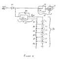
- FIG. 2schematically shows a circuit that may be used to implement illustrative embodiments of the invention.
- FIG. 3graphically shows approximate current flow through the current limiting element shown in FIG. 2 as a function of time.
- FIG. 4schematically shows another circuit that may be used to implement illustrative embodiments of the invention.
- a cooling systemincludes a charge storage element that charges while a heat generating element (e.g., a light bulb) is energized, and discharges to power a cooling fan that cools the heat generating element when power is turned off (e.g., when the heat generating element is not energized).
- a heat generating elemente.g., a light bulb
- a cooling fanthat cools the heat generating element when power is turned off (e.g., when the heat generating element is not energized).
- powermay be turned off unexpectedly during a power outage, or merely when the system no longer is connected to a power source.
- some embodiments of the inventioninclude a limiting element for limiting power flow to the charge storage element, particularly during start-up.
- the limiting elementis specifically configured to the requirements of the overall system to optimize start-up power flow to such elements. More specifically, the limiting element ensures that the charge storage element does not draw so much power that other system components cannot operate relatively quickly after power initially is applied. Details of various embodiments are discussed below.
- FIG. 1schematically shows a system 10 with a heat generating element 12 and a cooling element 14 configured to cool the heat generating element 12 in accordance with illustrative embodiments of the invention.
- the system 10is a high intensity projector light system (“light system”) having a heat generating bulb that can damage other components and/or itself if not sufficiently cooled.
- the cooling element 14is configured to continue to cool the bulb for a specified time even when power no longer is delivered to the system 10 . In other words, the cooling element 14 continues to cool the bulb for a specified time even after a power outage or some other type of power loss occurs.
- the cooling element 14includes a charge storage element 16 that stores power for such purposes.
- illustrative embodimentsmay be applied to a variety of heat generating systems that require cooling.
- illustrative embodimentsmay be applied to electronic components, such as microprocessors, digital, and analog circuit elements, or other types of lighting systems, such as medical lighting systems.
- FIG. 2schematically shows details of a cooling element 14 configured in accordance with illustrative embodiments of the invention.
- the cooling element 14includes a conventional electric fan 18 (e.g., one of the DC fans distributed by Comair Rotron, Inc. of San Diego, Calif.) for directing air flow toward the bulb (shown in FIG. 1 ), an input 20 for receiving a DC voltage to power the cooling element 14 , and the above noted charge storage element 16 , which powers the fan 18 for a limited time when no DC voltage is received at the input 20 .
- the input voltageis an AC voltage.
- conventional conversion circuitrye.g., rectifiers
- the fan 18includes a rotor 19 with an attached propeller for generating air flow, and commutation circuitry 21 for controlling the rotation of the rotor 19 .
- the commutation circuitmay be similar to those commonly used in conventional DC motors. It should be noted that the term, “commutation circuitry” is used to mean both electronically or mechanically commutation circuitry. Accordingly, the commutation circuitry may be the circuitry used in brushless or brush-type motors.
- the fan 18may be an AC fan. In such case, conversion circuitry (not shown) is included between the charge storage element 16 and fan 18 to convert DC voltage/current to AC voltage/current.
- the cooling element 14also includes a limiting element (hereinafter “current limiting circuit 22 ) regulating current flow to and from the charge storage element 16 .
- the current limiting circuit 22may be a positive temperature coefficient thermistor (referred to herein and known in the art as a “PTC”), which has a resistance that is related to its temperature and the current flowing through it. Details of various embodiments of the current limiting circuit 22 are discussed below.
- a diode D 1also is connected between the input 20 and the commutation circuitry 19 to ensure that current does not flow back to the input 20 when the charge storage element 16 discharges.
- the charge storage element 16includes a plurality of capacitors C 1 -C 6 connected in series.
- each capacitorhas substantially identical capacitance and voltage.
- each capacitormay have a rated capacitance of 6.8 farads with a rated voltage of 2.5 volts.
- the total maximum voltage of the series capacitors C 1 -C 6 shownthus equals fifteen volts. Accordingly, this configuration should suffice when the input voltage does not exceed fifteen volts.
- Each capacitoralso has a corresponding parallel resistor (the plurality of resistors being identified as resistors R 1 -R 6 ) to ensure that the voltage across all the capacitors C 1 -C 6 is substantially the same.
- capacitor C 1is in parallel with resistor R 1
- capacitor C 2is in parallel with resistor R 2 , etc. . . .
- the resistors R 1 -R 6also illustratively have the same resistance to ensure that each capacitor stores the same charge (i.e., voltage).
- the resistance of each resistormay be set to be relatively high to minimize current draw by the resistors R 1 -R 6 .
- the resistors R 1 -R 6each may be 50 kiloohms, which should draw a negligible current when used with the above noted voltages and elements.
- the current limiting circuit 22illustratively may be a PTC (also referred to as “PTC 22 ”).
- the PTC 22may be a threshold type PTC, such as those distributed by Raychem Corporation, which currently is a subsidiary of Tyco International Ltd.
- a threshold type PTCmaintains a relatively low resistance until it reaches a specified temperature. When the PTC 22 reaches this temperature, which is referred to in the art as the “trip point,” its resistance immediately jumps to a pre-specified higher level. This increased resistance consequently significantly limits current flow through the PTC 22 , thus reducing current flow to the capacitors C 1 -C 6 .
- the trip pointmay occur when the PTC 22 senses 1 amp of current, and the significantly decreased current flow may be 200 milliamps.
- FIG. 3graphically shows an approximation of current flow through the PTC 22 from start-up to the time the capacitors C 1 -C 6 are fully charged. It should be noted that FIG. 3 is not drawn to scale. Accordingly, FIG. 3 is provided for convenience purposes. Moreover, another PTC may be used that has different current flow characteristics. Such a PTC nevertheless has characteristics that are consistent with the goals of various embodiments of the invention.
- the capacitors C 1 -C 6initially draw a significant amount of current from the DC input 20 .
- This high current drawsubstantially immediately (e.g., in less than one second) increases the temperature of the PTC 22 to its trip point, which causes it to significantly increase its resistance.
- this increased resistancesignificantly limits the current that the capacitors C 1 -C 6 can draw (see time T 2 ). Accordingly, after time T 1 , the fan 18 draws the substantial majority of the current from the DC input 20 , thus permitting it to begin cooling the bulb substantially immediately at start-up.
- the capacitors C 1 -C 6undesirably would draw a significant amount of the input current during start up, consequently drawing current away from the fan 18 . This could damage the bulb or other system components because the fan 18 would not start cooling the bulb until a later time.
- the PTC 22gradually cools after the current through it abruptly decreases. Consequently, its resistance lowers, thus permitting an increasing amount of current to flow to the capacitors C 1 -C 6 (see time T 2 to time T 3 ).
- the system componentsare selected so that this increasing current is not high enough to cause the PTC 22 to again heat to its trip point. In addition, this increasing current should not be large enough to significantly affect fan operation.
- the current draw to the capacitors C 1 -C 6increases from the abruptly decreased current (i.e., time T 2 ) to a maximum current (i.e., time T 3 ), and then begins to decrease as the capacitors C 1 -C 6 require a lower current draw. The capacitor current draw continues to decrease to zero, at which point the capacitors C 1 -C 6 are substantially fully charged (i.e., time T 4 ).
- the PTC 22is configured to permit the capacitors C 1 -C 6 to charge in a manner that does not significantly interfere with the operation of the fan 18 .
- the fan 18should be able to accomplish its intended function; i.e., rotating at a rate that is substantially the same as, or slightly slower than (but sufficient for the intended application), the rate it would rotate if the capacitors C 1 -C 6 were not coupled.
- Proper selection of the PTC 22e.g., trip current and reduced current
- the PTC 22can determine an amount of current required by the commutation circuitry 21 to sufficiently rotate the fan 18 during start-up. Based upon this value, the PTC 22 can be selected. Accordingly, the PTC 22 is selected (i.e., it is configured) as a function of the requirements of the commutation circuitry 21 .
- the capacitors C 1 -C 6immediately begin to discharge. Accordingly, during discharge, current flows from the capacitors C 1 -C 6 to the commutation circuit, thus causing the rotor to continue to turn until the capacitors C 1 -C 6 are substantially fully discharged. As noted above, the diode D 1 ensures that the capacitor discharge current does not flow to the input 20 .
- the capacitor discharge currentillustratively is not large enough to cause the PTC 22 to reach its trip point.
- the resistors R 1 -R 6are eliminated. In yet other embodiments, additional or fewer capacitors may be used. Among other factors, the total number of capacitors used is dependent upon the input voltage, capacitance and voltage of each capacitor, and the time period required (e.g., one, two, three, or more minutes) for energizing the commutation circuitry after power is turned off.
- FIG. 4schematically shows another embodiment of the cooling element 14 with an alternative current limiting circuit 22 .
- the current limiting circuit 22is a constant current device configured to provide a constant current draw to the capacitors C 1 -C 6 .
- the current limiting module in this embodimentmay be an integrated circuit, such as a model number LM317M adjustable linear voltage/current regulator, distributed by National Semiconductor Corporation of Santa Clara, Calif. If using the LM317M, the current limiting module includes a return diode D 2 for permitting current to flow from the capacitors to the fan 18 , and a current limit resistor R-lim that sets the constant current value of the LM317M. Accordingly, the constant current value may be externally modified simply by changing the current limit resistor R-lim.
- the PTC 22 and adjustable linear voltage/current regulator circuitare exemplary and not intended to limit all embodiments of the invention.
Landscapes
- Physics & Mathematics (AREA)
- Engineering & Computer Science (AREA)
- Microelectronics & Electronic Packaging (AREA)
- General Physics & Mathematics (AREA)
- Thermal Sciences (AREA)
- Control Of Positive-Displacement Air Blowers (AREA)
- Control Of Electric Motors In General (AREA)
Abstract
Description
Claims (27)
Priority Applications (1)
| Application Number | Priority Date | Filing Date | Title |
|---|---|---|---|
| US10/616,499US7314350B2 (en) | 2002-07-22 | 2003-07-09 | Energy store circuit for controlling rotor rotation |
Applications Claiming Priority (3)
| Application Number | Priority Date | Filing Date | Title |
|---|---|---|---|
| US39769402P | 2002-07-22 | 2002-07-22 | |
| US41782702P | 2002-10-11 | 2002-10-11 | |
| US10/616,499US7314350B2 (en) | 2002-07-22 | 2003-07-09 | Energy store circuit for controlling rotor rotation |
Publications (2)
| Publication Number | Publication Date |
|---|---|
| US20040036431A1 US20040036431A1 (en) | 2004-02-26 |
| US7314350B2true US7314350B2 (en) | 2008-01-01 |
Family
ID=30773033
Family Applications (1)
| Application Number | Title | Priority Date | Filing Date |
|---|---|---|---|
| US10/616,499Expired - LifetimeUS7314350B2 (en) | 2002-07-22 | 2003-07-09 | Energy store circuit for controlling rotor rotation |
Country Status (4)
| Country | Link |
|---|---|
| US (1) | US7314350B2 (en) |
| AU (1) | AU2003253819A1 (en) |
| CA (1) | CA2489351C (en) |
| WO (1) | WO2004010061A2 (en) |
Cited By (3)
| Publication number | Priority date | Publication date | Assignee | Title |
|---|---|---|---|---|
| US20130259722A1 (en)* | 2012-03-29 | 2013-10-03 | Hon Hai Precision Industry Co., Ltd. | Fan |
| US8766602B1 (en) | 2010-08-30 | 2014-07-01 | Enerdel, Inc. | Self protecting pre-charge circuit |
| US20140192484A1 (en)* | 2013-01-04 | 2014-07-10 | Hon Hai Precision Industry Co., Ltd. | Fan controlling system and electronic device using same |
Families Citing this family (1)
| Publication number | Priority date | Publication date | Assignee | Title |
|---|---|---|---|---|
| CN105792606B (en)* | 2016-03-31 | 2017-12-26 | 海信集团有限公司 | The heat dissipating method of fan rotational frequency control method, device and optical projection system |
Citations (17)
| Publication number | Priority date | Publication date | Assignee | Title |
|---|---|---|---|---|
| US3841746A (en) | 1973-02-26 | 1974-10-15 | A Chase | Control for synchronizing projectors with an audio program |
| US4494055A (en) | 1983-06-09 | 1985-01-15 | General Electric Company | Control circuit for an electronically commutated motor including reversing; method of operating an ECM including reversing |
| US4499408A (en) | 1983-06-09 | 1985-02-12 | General Electric Company | Control circuit for an electronically commutated motor, an integrated circuit for an ECM, and a method of operating an ECM |
| US4500821A (en) | 1983-06-09 | 1985-02-19 | General Electric Company | Speed or torque control circuit for an electronically commutated motor (ECM) and method of controlling the torque or speed of an ECM |
| US4535275A (en) | 1981-12-23 | 1985-08-13 | Papst-Motoren Gmbh & Co., Kg | Brushless D-C motor system with improved commutation circuit |
| US4618803A (en)* | 1984-11-19 | 1986-10-21 | Polaroid Corporation | Current limited strobe charge circuit |
| US4751398A (en) | 1986-03-18 | 1988-06-14 | The Bodine Company | Lighting system for normal and emergency operation of high intensity discharge lamps |
| JPH01123419A (en) | 1987-11-09 | 1989-05-16 | Nec Corp | Projection exposure apparatus |
| JPH0352575A (en) | 1989-07-19 | 1991-03-06 | Mitsubishi Electric Corp | Cooling device utilizing regenerated energy |
| JPH0698479A (en) | 1992-09-10 | 1994-04-08 | Toshiba Lighting & Technol Corp | Discharge lamp lighting circuit |
| US5619076A (en) | 1994-12-19 | 1997-04-08 | General Signal Power Systems, Inc. | Method and apparatus for connection and disconnection of batteries to uninterruptible power systems and the like |
| JPH10197952A (en) | 1997-01-10 | 1998-07-31 | Musashi Seimitsu Ind Co Ltd | Overhead projector |
| JPH11231419A (en) | 1998-02-17 | 1999-08-27 | Tokin Ceramics Kk | Projector |
| JP2000021457A (en) | 1998-07-03 | 2000-01-21 | Hitachi Ltd | Energy storage system |
| US6388392B1 (en)* | 1999-03-23 | 2002-05-14 | Hubbell Incorporated | System for providing auxiliary power to lighting unit for heavy equipment having a direct current power supply and no uninterruptible power supply |
| US6709111B2 (en)* | 2001-06-01 | 2004-03-23 | Sanyo Electric Co., Ltd. | Cooling fan controller and liquid crystal projector |
| US7137015B2 (en) | 2003-05-12 | 2006-11-14 | Enermax Technology Corporation | Switching power supply having cooling fan cooling down system after power turned off |
Family Cites Families (4)
| Publication number | Priority date | Publication date | Assignee | Title |
|---|---|---|---|---|
| DE3542776A1 (en) | 1985-12-04 | 1987-07-23 | Kurt G Dipl Ing Fickelscher | ROLL-RING MACHINE FOR COMPRESSING AND CONVEYING FLUIDS |
| IT1240629B (en) | 1990-04-11 | 1993-12-17 | Epifanio Leanza | VOLUME VARIATION ROTATING FLUID DYNAMIC MACHINE |
| BE1006323A3 (en) | 1992-11-03 | 1994-07-19 | Eelbode Hugo | Rotating, volumetric compressor/motor with centrally controlled blades |
| JPH1123419A (en)* | 1997-06-30 | 1999-01-29 | Ando Electric Co Ltd | Apparatus for measuring characteristics of optical fiber |
- 2003
- 2003-07-09CACA2489351Apatent/CA2489351C/ennot_activeExpired - Fee Related
- 2003-07-09AUAU2003253819Apatent/AU2003253819A1/ennot_activeAbandoned
- 2003-07-09USUS10/616,499patent/US7314350B2/ennot_activeExpired - Lifetime
- 2003-07-09WOPCT/US2003/021284patent/WO2004010061A2/ennot_activeApplication Discontinuation
Patent Citations (17)
| Publication number | Priority date | Publication date | Assignee | Title |
|---|---|---|---|---|
| US3841746A (en) | 1973-02-26 | 1974-10-15 | A Chase | Control for synchronizing projectors with an audio program |
| US4535275A (en) | 1981-12-23 | 1985-08-13 | Papst-Motoren Gmbh & Co., Kg | Brushless D-C motor system with improved commutation circuit |
| US4494055A (en) | 1983-06-09 | 1985-01-15 | General Electric Company | Control circuit for an electronically commutated motor including reversing; method of operating an ECM including reversing |
| US4499408A (en) | 1983-06-09 | 1985-02-12 | General Electric Company | Control circuit for an electronically commutated motor, an integrated circuit for an ECM, and a method of operating an ECM |
| US4500821A (en) | 1983-06-09 | 1985-02-19 | General Electric Company | Speed or torque control circuit for an electronically commutated motor (ECM) and method of controlling the torque or speed of an ECM |
| US4618803A (en)* | 1984-11-19 | 1986-10-21 | Polaroid Corporation | Current limited strobe charge circuit |
| US4751398A (en) | 1986-03-18 | 1988-06-14 | The Bodine Company | Lighting system for normal and emergency operation of high intensity discharge lamps |
| JPH01123419A (en) | 1987-11-09 | 1989-05-16 | Nec Corp | Projection exposure apparatus |
| JPH0352575A (en) | 1989-07-19 | 1991-03-06 | Mitsubishi Electric Corp | Cooling device utilizing regenerated energy |
| JPH0698479A (en) | 1992-09-10 | 1994-04-08 | Toshiba Lighting & Technol Corp | Discharge lamp lighting circuit |
| US5619076A (en) | 1994-12-19 | 1997-04-08 | General Signal Power Systems, Inc. | Method and apparatus for connection and disconnection of batteries to uninterruptible power systems and the like |
| JPH10197952A (en) | 1997-01-10 | 1998-07-31 | Musashi Seimitsu Ind Co Ltd | Overhead projector |
| JPH11231419A (en) | 1998-02-17 | 1999-08-27 | Tokin Ceramics Kk | Projector |
| JP2000021457A (en) | 1998-07-03 | 2000-01-21 | Hitachi Ltd | Energy storage system |
| US6388392B1 (en)* | 1999-03-23 | 2002-05-14 | Hubbell Incorporated | System for providing auxiliary power to lighting unit for heavy equipment having a direct current power supply and no uninterruptible power supply |
| US6709111B2 (en)* | 2001-06-01 | 2004-03-23 | Sanyo Electric Co., Ltd. | Cooling fan controller and liquid crystal projector |
| US7137015B2 (en) | 2003-05-12 | 2006-11-14 | Enermax Technology Corporation | Switching power supply having cooling fan cooling down system after power turned off |
Cited By (3)
| Publication number | Priority date | Publication date | Assignee | Title |
|---|---|---|---|---|
| US8766602B1 (en) | 2010-08-30 | 2014-07-01 | Enerdel, Inc. | Self protecting pre-charge circuit |
| US20130259722A1 (en)* | 2012-03-29 | 2013-10-03 | Hon Hai Precision Industry Co., Ltd. | Fan |
| US20140192484A1 (en)* | 2013-01-04 | 2014-07-10 | Hon Hai Precision Industry Co., Ltd. | Fan controlling system and electronic device using same |
Also Published As
| Publication number | Publication date |
|---|---|
| AU2003253819A1 (en) | 2004-02-09 |
| CA2489351A1 (en) | 2004-01-29 |
| US20040036431A1 (en) | 2004-02-26 |
| WO2004010061A2 (en) | 2004-01-29 |
| WO2004010061A3 (en) | 2004-03-18 |
| AU2003253819A8 (en) | 2004-02-09 |
| CA2489351C (en) | 2011-01-11 |
Similar Documents
| Publication | Publication Date | Title |
|---|---|---|
| US4856078A (en) | DC fan speed control | |
| JP3272493B2 (en) | Starting device for single-phase induction motor | |
| JP2001284868A (en) | Cooling fan control device | |
| US9106149B2 (en) | Start-up circuitry | |
| JP6430496B2 (en) | A bleeder circuit for a non-linear light load dimmer. | |
| US7314350B2 (en) | Energy store circuit for controlling rotor rotation | |
| US5220258A (en) | Drive circuit for a brushless direct-current motor | |
| US5598073A (en) | Drive circuit for a brushless direct-current motor | |
| US5705903A (en) | Electric brake for an alternating current motor | |
| JP3519048B2 (en) | Voltage control device for vehicle alternator | |
| JP3621217B2 (en) | Self-oscillation drive control circuit | |
| EP0778646A2 (en) | Rush current suppression circuit | |
| JP3530449B2 (en) | Inverter driven motor device | |
| EP1246354B1 (en) | Motor starter circuit, particularly for refrigerator compressors, having improved characteristics. | |
| US5168207A (en) | Three level control system for a voltage dependent load | |
| JP2000010647A (en) | Fan driving control circuit | |
| US20030210007A1 (en) | Input power control device | |
| CN118934712A (en) | Fan speed control circuit, fan equipment and electric heating equipment | |
| JP2819867B2 (en) | Power supply | |
| KR0126129Y1 (en) | Operation control circuit of a brushless motor | |
| JP3661305B2 (en) | DC power supply | |
| JP4830219B2 (en) | Fan motor drive circuit | |
| JP2576096B2 (en) | Engine generator | |
| JP2827205B2 (en) | Vehicle charging control device | |
| JPS61207147A (en) | Image former |
Legal Events
| Date | Code | Title | Description |
|---|---|---|---|
| AS | Assignment | Owner name:COMAIR ROTRON, INC., CALIFORNIA Free format text:ASSIGNMENT OF ASSIGNORS INTEREST;ASSIGNOR:BROWN, FRED A.;REEL/FRAME:014619/0422 Effective date:20030803 | |
| AS | Assignment | Owner name:LASALLE BANK NATIONAL ASSOCIATION, ILLINOIS Free format text:SECURITY INTEREST;ASSIGNOR:COMAIR ROTRON, INC., A DELAWARE CORPORATION;REEL/FRAME:015190/0852 Effective date:20040402 Owner name:LASALLE BANK NATIONAL ASSOCIATION,ILLINOIS Free format text:SECURITY INTEREST;ASSIGNOR:COMAIR ROTRON, INC., A DELAWARE CORPORATION;REEL/FRAME:015190/0852 Effective date:20040402 | |
| STCF | Information on status: patent grant | Free format text:PATENTED CASE | |
| CC | Certificate of correction | ||
| FPAY | Fee payment | Year of fee payment:4 | |
| FPAY | Fee payment | Year of fee payment:8 | |
| AS | Assignment | Owner name:MOTION HOLDINGS, LLC, DELAWARE Free format text:CHANGE OF NAME;ASSIGNOR:COMAIR ROTRON, INC.;REEL/FRAME:036887/0929 Effective date:20081014 | |
| MAFP | Maintenance fee payment | Free format text:PAYMENT OF MAINTENANCE FEE, 12TH YEAR, LARGE ENTITY (ORIGINAL EVENT CODE: M1553); ENTITY STATUS OF PATENT OWNER: LARGE ENTITY Year of fee payment:12 |