US7313246B2 - Information system using eyewear for communication - Google Patents
Information system using eyewear for communicationDownload PDFInfo
- Publication number
- US7313246B2 US7313246B2US09/972,342US97234201AUS7313246B2US 7313246 B2US7313246 B2US 7313246B2US 97234201 AUS97234201 AUS 97234201AUS 7313246 B2US7313246 B2US 7313246B2
- Authority
- US
- United States
- Prior art keywords
- wearer
- speaker
- microphone
- earstem
- eyeglasses
- Prior art date
- Legal status (The legal status is an assumption and is not a legal conclusion. Google has not performed a legal analysis and makes no representation as to the accuracy of the status listed.)
- Expired - Lifetime, expires
Links
- 238000004891communicationMethods0.000titleclaimsabstractdescription45
- 238000000034methodMethods0.000claimsdescription16
- 210000000883ear externalAnatomy0.000claimsdescription10
- 230000001413cellular effectEffects0.000claimsdescription8
- 230000008569processEffects0.000claimsdescription5
- 230000007613environmental effectEffects0.000claimsdescription3
- 230000002123temporal effectEffects0.000claims2
- 230000000717retained effectEffects0.000claims1
- 230000015654memoryEffects0.000description28
- 238000001356surgical procedureMethods0.000description13
- 230000035897transcriptionEffects0.000description13
- 238000013518transcriptionMethods0.000description12
- 210000003128headAnatomy0.000description10
- 210000000613ear canalAnatomy0.000description7
- 239000004020conductorSubstances0.000description6
- 238000013461designMethods0.000description5
- 230000006870functionEffects0.000description5
- 239000000463materialSubstances0.000description5
- 239000004033plasticSubstances0.000description5
- 230000001681protective effectEffects0.000description4
- 239000000853adhesiveSubstances0.000description3
- 230000001070adhesive effectEffects0.000description3
- 230000008901benefitEffects0.000description3
- 230000000249desinfective effectEffects0.000description3
- 238000005516engineering processMethods0.000description3
- 230000003287optical effectEffects0.000description3
- 239000000243solutionSubstances0.000description3
- RTAQQCXQSZGOHL-UHFFFAOYSA-NTitaniumChemical compound[Ti]RTAQQCXQSZGOHL-UHFFFAOYSA-N0.000description2
- 238000005452bendingMethods0.000description2
- 230000015572biosynthetic processEffects0.000description2
- 230000006835compressionEffects0.000description2
- 238000007906compressionMethods0.000description2
- 238000007796conventional methodMethods0.000description2
- 239000006260foamSubstances0.000description2
- QSHDDOUJBYECFT-UHFFFAOYSA-NmercuryChemical compound[Hg]QSHDDOUJBYECFT-UHFFFAOYSA-N0.000description2
- 229910052753mercuryInorganic materials0.000description2
- 229910052751metalInorganic materials0.000description2
- 239000002184metalSubstances0.000description2
- 238000003825pressingMethods0.000description2
- 238000012545processingMethods0.000description2
- 230000004044responseEffects0.000description2
- 230000001360synchronised effectEffects0.000description2
- 239000010936titaniumSubstances0.000description2
- 229910052719titaniumInorganic materials0.000description2
- LFQSCWFLJHTTHZ-UHFFFAOYSA-NEthanolChemical compoundCCOLFQSCWFLJHTTHZ-UHFFFAOYSA-N0.000description1
- 229910001069Ti alloyInorganic materials0.000description1
- 239000000654additiveSubstances0.000description1
- 230000000996additive effectEffects0.000description1
- 239000006117anti-reflective coatingSubstances0.000description1
- 208000003464asthenopiaDiseases0.000description1
- 230000000903blocking effectEffects0.000description1
- 210000001124body fluidAnatomy0.000description1
- 239000010839body fluidSubstances0.000description1
- 230000008859changeEffects0.000description1
- 239000003795chemical substances by applicationSubstances0.000description1
- 239000011248coating agentSubstances0.000description1
- 238000000576coating methodMethods0.000description1
- 238000004590computer programMethods0.000description1
- 238000012790confirmationMethods0.000description1
- 238000002788crimpingMethods0.000description1
- 238000003745diagnosisMethods0.000description1
- 238000009429electrical wiringMethods0.000description1
- 239000012530fluidSubstances0.000description1
- 230000002209hydrophobic effectEffects0.000description1
- 238000001746injection mouldingMethods0.000description1
- 239000012212insulatorSubstances0.000description1
- 229910001092metal group alloyInorganic materials0.000description1
- 238000012986modificationMethods0.000description1
- 230000004048modificationEffects0.000description1
- 230000008447perceptionEffects0.000description1
- 239000004417polycarbonateSubstances0.000description1
- 229920000515polycarbonatePolymers0.000description1
- 230000002035prolonged effectEffects0.000description1
- 239000011241protective layerSubstances0.000description1
- 230000009467reductionEffects0.000description1
- 238000012552reviewMethods0.000description1
- 239000004065semiconductorSubstances0.000description1
- 238000003786synthesis reactionMethods0.000description1
- 230000000007visual effectEffects0.000description1
Images


Classifications
- H—ELECTRICITY
- H04—ELECTRIC COMMUNICATION TECHNIQUE
- H04M—TELEPHONIC COMMUNICATION
- H04M1/00—Substation equipment, e.g. for use by subscribers
- H04M1/02—Constructional features of telephone sets
- H04M1/04—Supports for telephone transmitters or receivers
- H04M1/05—Supports for telephone transmitters or receivers specially adapted for use on head, throat or breast
- G—PHYSICS
- G02—OPTICS
- G02C—SPECTACLES; SUNGLASSES OR GOGGLES INSOFAR AS THEY HAVE THE SAME FEATURES AS SPECTACLES; CONTACT LENSES
- G02C11/00—Non-optical adjuncts; Attachment thereof
- G02C11/10—Electronic devices other than hearing aids
- H—ELECTRICITY
- H04—ELECTRIC COMMUNICATION TECHNIQUE
- H04B—TRANSMISSION
- H04B1/00—Details of transmission systems, not covered by a single one of groups H04B3/00 - H04B13/00; Details of transmission systems not characterised by the medium used for transmission
- H04B1/38—Transceivers, i.e. devices in which transmitter and receiver form a structural unit and in which at least one part is used for functions of transmitting and receiving
- H04B1/3827—Portable transceivers
- H04B1/385—Transceivers carried on the body, e.g. in helmets
- H04B2001/3855—Transceivers carried on the body, e.g. in helmets carried in a belt or harness
- H—ELECTRICITY
- H04—ELECTRIC COMMUNICATION TECHNIQUE
- H04B—TRANSMISSION
- H04B1/00—Details of transmission systems, not covered by a single one of groups H04B3/00 - H04B13/00; Details of transmission systems not characterised by the medium used for transmission
- H04B1/38—Transceivers, i.e. devices in which transmitter and receiver form a structural unit and in which at least one part is used for functions of transmitting and receiving
- H04B1/3827—Portable transceivers
- H04B1/385—Transceivers carried on the body, e.g. in helmets
- H04B2001/3866—Transceivers carried on the body, e.g. in helmets carried on the head
- H—ELECTRICITY
- H04—ELECTRIC COMMUNICATION TECHNIQUE
- H04R—LOUDSPEAKERS, MICROPHONES, GRAMOPHONE PICK-UPS OR LIKE ACOUSTIC ELECTROMECHANICAL TRANSDUCERS; DEAF-AID SETS; PUBLIC ADDRESS SYSTEMS
- H04R1/00—Details of transducers, loudspeakers or microphones
- H04R1/10—Earpieces; Attachments therefor ; Earphones; Monophonic headphones
- H04R1/1041—Mechanical or electronic switches, or control elements
- H—ELECTRICITY
- H04—ELECTRIC COMMUNICATION TECHNIQUE
- H04R—LOUDSPEAKERS, MICROPHONES, GRAMOPHONE PICK-UPS OR LIKE ACOUSTIC ELECTROMECHANICAL TRANSDUCERS; DEAF-AID SETS; PUBLIC ADDRESS SYSTEMS
- H04R1/00—Details of transducers, loudspeakers or microphones
- H04R1/10—Earpieces; Attachments therefor ; Earphones; Monophonic headphones
- H04R1/1058—Manufacture or assembly
- H04R1/1066—Constructional aspects of the interconnection between earpiece and earpiece support
- H—ELECTRICITY
- H04—ELECTRIC COMMUNICATION TECHNIQUE
- H04R—LOUDSPEAKERS, MICROPHONES, GRAMOPHONE PICK-UPS OR LIKE ACOUSTIC ELECTROMECHANICAL TRANSDUCERS; DEAF-AID SETS; PUBLIC ADDRESS SYSTEMS
- H04R2201/00—Details of transducers, loudspeakers or microphones covered by H04R1/00 but not provided for in any of its subgroups
- H04R2201/10—Details of earpieces, attachments therefor, earphones or monophonic headphones covered by H04R1/10 but not provided for in any of its subgroups
- H04R2201/107—Monophonic and stereophonic headphones with microphone for two-way hands free communication
- H—ELECTRICITY
- H04—ELECTRIC COMMUNICATION TECHNIQUE
- H04R—LOUDSPEAKERS, MICROPHONES, GRAMOPHONE PICK-UPS OR LIKE ACOUSTIC ELECTROMECHANICAL TRANSDUCERS; DEAF-AID SETS; PUBLIC ADDRESS SYSTEMS
- H04R2420/00—Details of connection covered by H04R, not provided for in its groups
- H04R2420/07—Applications of wireless loudspeakers or wireless microphones
- H—ELECTRICITY
- H04—ELECTRIC COMMUNICATION TECHNIQUE
- H04R—LOUDSPEAKERS, MICROPHONES, GRAMOPHONE PICK-UPS OR LIKE ACOUSTIC ELECTROMECHANICAL TRANSDUCERS; DEAF-AID SETS; PUBLIC ADDRESS SYSTEMS
- H04R5/00—Stereophonic arrangements
- H04R5/033—Headphones for stereophonic communication
- H04R5/0335—Earpiece support, e.g. headbands or neckrests
Definitions
- Embodimentsrelate to personal wireless communication systems, in particular to such systems using eyewear configured for two-way communication, and most particularly to such systems and eyewear for use by medical personnel.
- a microphone and a speakerare positioned in protective eyewear.
- the microphone and speakerare coupled to a wearer unit worn by the eyewear wearer.
- a neck strapcouples the eyewear and the wearer unit.
- the wearer unitexchanges wireless (e.g., radio) signals with a base station.
- the wireless signalsinclude information from a signal generated by the microphone and information for a signal to be output by the speaker.
- the base stationmay be coupled to devices such as surgical theater equipment and/or coupled to a telecommunication system.
- the systemenables the eyewear wearer to perform numerous hands-free communications.
- the wearermay use the eyewear to conduct a hands-free telephone conversation in situations where the wearer's hands cannot be used (e.g., while performing surgery).
- the wearermay use the eyeglasses to dictate notes to be transcribed (e.g., surgical notes).
- the wearermay use the eyeglasses to control, and in some cases receive information from, the devices coupled to the base station.
- the wearerreceives data.
- the datais output to the wearer as, for example, synthesized voice or as an image on a video display coupled with the eyewear.
- FIG. 1is a perspective view showing an embodiment of protective eyewear for two-way communication.
- FIG. 2is a side elevation view showing illustrative wear of eyewear and wearer communication unit embodiments.
- FIG. 3is a front elevation view showing speaker position in relation to the wearer's ear.
- FIG. 4is a perspective view showing a second embodiment of protective eyewear for two-way communication.
- FIG. 5is a side cross-sectional and cutaway view of a speaker mount.
- FIG. 6is a top cross-sectional and cutaway view of a speaker mount.
- FIG. 7is a side elevation view of an earstem and speaker combination.
- FIG. 8is another side elevation view of an earstem and speaker combination.
- FIG. 9is a side cutaway view of an earstem portion.
- FIGS. 10A , 10 B, and 10 Care cross-sectional views of an earstem.
- FIG. 11is a side cutaway view of a microphone housing embodiment.
- FIG. 12is a side elevation view of a second earstem and speaker combination.
- FIG. 13is a side elevation view of a third earstem and speaker combination.
- FIG. 14is a top plan view of an electrically conductive neck strap.
- FIG. 15is a perspective view showing a third embodiment of protective eyewear for two-way communication.
- FIG. 16is an exploded perspective view showing a speaker mount assembly.
- FIG. 17is a cross-sectional view of a speaker mounted in a support housing.
- FIGS. 18A and 18Bare exploded perspective views of a microphone housing.
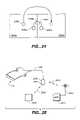
- FIGS. 19A and 19Bare views illustrating microphone directional pickup patterns.
- FIG. 20is a cross-sectional view of a microphone mounted in a microphone housing.
- FIG. 21is a diagrammatic view of a communication system using eyewear for communication.
- FIG. 22is a diagrammatic view of functional blocks in a wearer unit.
- FIG. 23is a diagrammatic view of functional blocks in a base station and associated devices.
- FIG. 24is a diagrammatic plan view of operating theaters.
- FIG. 25is a diagrammatic view of a second communication system using eyewear for communication.
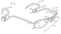
- FIG. 1is a perspective view showing an embodiment of eyewear for two-way communication used, for example, in a surgical theater.
- Eyeglasses 100are illustrative of many embodiments that include conventional eyeglasses configurations and eye protection gear such as goggles and face shields.
- Eyeglasses 100include eye protection portion 102 , left earstem 104 , and right earstem 106 .
- Eye protection portion 102protects the wearer's eyes from, for example, body fluid splashes and other foreign objects that may erupt during surgery.
- Earstems 104 , 106rest on the wearer's external outer ears and help hold eye protection portion 102 on the wearer's head.
- Eye protection portionincludes left lens 108 and right lens 110 coupled by nose bridge 112 . Nose pads 114 are coupled to nose bridge 112 .
- the eyeglasses 100 shown in FIG. 1are frameless—there is no supporting frame around the lenses. An illustrative framed embodiment is described below.
- lenses 108 , 110are corrective lenses. Some lenses 108 , 110 correct the wearer's vision for near work on a surgical patient. Other lenses 108 , 110 correct the wearer's vision for both near and more distant vision (i.e., bifocals) so that the wearer clearly sees, for example, both the patient and a video monitor displaying an endoscope camera image. In some instances lenses 108 , 110 are non-corrective.
- Lenses 108 , 110may be tinted to reduce the wearer's eyestrain and/or to improve visual contrast in the wearer's field of view.
- an antireflective coatingis formed over the lenses.
- the lensesare treated with a hydrophobic agent (functioning, for example, similar to RAIN-X, marketed by Blue Coral-Slick 50, Ltd., Cleveland Ohio) that enables fluid to more easily run off the lenses.
- the lensesattenuate transmitted light as sunglasses (e.g., RAY-BAN G-15 tint lenses, manufactured by Bausch & Lomb Incorporated).
- Earstem 104includes temple portion 116 , speaker support loop 118 , and ear piece 120 .
- FIG. 1shows that earstem 104 is configured as a single, continuously curving piece that forms temple portion 116 , support loop 118 , and ear piece 120 .
- Speaker support loop 118holds speaker mount 122 such that speaker 123 is positioned over the wearer's ear canal. In some cases speaker mount 122 is omitted and speaker 123 is directly held by support loop 118 .
- support loop 118is shown open on one end. A support piece may be added across the open end of loop 118 .
- FIG. 1also shows that the sides of support loop 118 are straight, although in some instances one or both sides of support loop 118 may be curved.
- FIG. 2illustrates wear of an embodiment, showing the position of earstem 104 on the wearer's head.
- Ear piece 120rests on the wearer's external outer ear.
- Loop 118supports the speaker over the wearer's ear.
- FIG. 3is a front view showing a detail of the speaker mount 122 position (hence, speaker 123 position) in relation to the wearer's ear.
- support loop 118is configured such that speaker mount 122 is held away from the wearer's ear so that a gap 300 exists between speaker 123 and the wearer's external outer ear. Gap 300 is made large enough so that external sound is not obstructed from reaching the wearer's ear canal.
- Support loop 118is rigid so that speaker mount 122 cannot be inadvertently pushed against the wearer's outer ear during use.
- speaker mount 122 positionis adjustable to allow the speaker to be aligned with the wearer's ear canal, as described below.
- speaker mount 122Since there is no contact between speaker mount 122 and the wearer's outer ear, speaker mount 122 does not obstruct the wearer's hearing from any angle. Any foam pads surrounding speaker 123 do not touch the outer ear. There are no cups that typically fit against the wearer's head in order to block external sound as in conventional headphones. If desired, however, support loop 118 can, in some instances, be modified so that mount 122 touches the external outer ear.
- microphone housing 124is integral to (formed as a continuous part of) temple portion 116 of earstem 104 .
- a surgical maskIn a surgical operating theater, much of the wearer's lower face is typically covered by a surgical mask and much of the head is covered by a surgical cap.
- a large housing or a boomcan be used to position a microphone close to the wearer's mouth, medical personnel, especially surgeons, prefer to keep as much equipment as possible away from their face and away from the mask and cap. If a boom is used, the microphone position can be altered if the boom is displaced when removed from the wearer's head. A boom can snag on other objects.
- an advantage of the integral microphone housingis that the wearer is unaware of the microphone's presence.
- Microphone housing 124is in one instance a space in which a microphone is placed. In other instances microphone housing 124 is, for example, a separate piece fitted into the eyeglasses that holds the microphone.
- housing 124is located on earstem 104 to be close to the wearer's mouth. In other instances, however, housing 124 is located elsewhere on eyeglasses 100 (e.g., on support loop 118 , on a frame surrounding one of the lenses ( FIG. 4 )). In FIG. 1 , microphone housing 124 is shown extending from temple portion 116 . In other instances in which temple portion 116 is sufficiently large, or the microphone is sufficiently small, housing 124 is coextensive with temple portion 116 so that there is no significant change in the cross section of the earstem in the microphone housing portion. Making the microphone housing coextensive with the shape of the earstem reduces accidental wear on or breakage of the housing.
- Additional microphonesare used in some embodiments to improve sound pickup quality. Such additional microphones are placed in various positions, such as on the same earstem, the opposite earstem, or on a frame supporting the lenses.
- the use of more than one microphone in various positions to improve sound pickup directionalityallows the wearer's voice to be sensed more clearly and extraneous background noises to more easily be canceled. Consequently, enhanced directionality improves performance of, for example, voice recognition software executed by digital signal processors described below, and improves the quality of the wearer's voice for remote conversation or for recording as dictation.
- opening 126is aligned in the direction of the wearer's mouth.
- the configuration of the right side of eyeglasses 100is essentially a mirror image of the left side as described above. In other instances, unnecessary features may be omitted from either the left or right sides.
- the support loop 118is omitted from right earstem 106 .
- the inventorshave discovered, however, that excellent sound quality is provided when a speaker (e.g., speakers in mounts 122 , 128 as shown in FIG. 1 ) is positioned over each of the wearer's intertragial notches, even though the speakers are held away from the external outer ears.
- FIG. 4is a perspective view showing a second embodiment of eyeglasses for two-way communication.
- Eyeglasses 400are similar to eyeglasses 100 , but illustrate a different configuration of the eye protection portion.
- eye protection portion 402has an illustrative frame 404 surrounding the lenses.
- Frame 404is conventionally coupled to earstems 104 , 106 .
- portions of frame 404may be omitted (e.g., to reduce weight).
- the eye protection portion 102 , 402may be made larger to protect other parts of the wearer's face.
- the microphone (not shown) in the eyeglassesis mounted in a microphone housing embodiment positioned in frame 404 .
- the microphonemay be mounted in the lower part 406 of frame 404 , near the wearer's mouth. Opening 408 , allowing sound to reach the microphone, is on the underside of frame 404 and is not visible in this view.
- FIG. 4also illustrates a microphone housing 410 embodiment that is coextensive with the shape of temple portion 116 of earstem 104 .
- FIGS. 1 and 4illustrate embodiments that include both speakers and a microphone, in other cases embodiments are configured with only a microphone or only one or more speakers.
- Earstems 104 , 106 and the frame supporting lenses 108 , 110are made from a rigid material such as plastic (e.g., SPX plastic), metal (e.g., titanium), or metal alloy (e.g., titanium alloy).
- plastice.g., SPX plastic
- metale.g., titanium
- metal alloye.g., titanium alloy
- An advantage of using an electrically conductive material for at least a portion of eyeglasses 100is that the electrically conductive material helps to shield electrical wiring and components in the eyewear against electromagnetic interference.
- a combination of plastic and metalis used to make eyewear 100 .
- Conventional wearer comfort features, such as soft rubber pads on the ear pieces,are used in various embodiments.
- the exposed materials in the eyewearare tolerant of wipedown using disinfecting solutions (e.g., alcohol).
- disinfecting solutionse.g., alcohol
- the wearershould be cautious not to use a disinfecting solution that removes an optical coating on the lenses that is soluble by the disinfecting solution.
- eyeglasses 100 , 400are provided to fit various wearer head sizes. Further fitting to the wearer's head is conventionally done (e.g., by bending the earstems).
- FIG. 5is a side cutaway view of speaker mount 122 .
- Channel 502separates speaker housing 504 and retaining portion 506 .
- a portion of support loop 118( FIG. 1 ) rests in channel 502 .
- Channel 502is circular so that speaker mount 122 rotates within support loop 118 around axis 508 . In one instance the fit between loop 118 and mount 122 is tight enough so that mount 122 is held in place by friction.
- conductive pad 510is positioned in channel 502 and makes contact with a corresponding conductive strip positioned on the inside of loop 118 , described below.
- Conventional small speaker 123is positioned in speaker housing 504 and is conventionally held in place using, for example, adhesive or a press fit. In some instances the surface 514 closest to the wearer's ear is covered by a conventional protective layer (e.g., foam) (not shown).
- FIG. 5shows that speaker 123 is mounted off-axis from axis 508 . Hence speaker 123 moves in relation to support loop 118 as mount 122 rotates. In some instances, however, speaker 123 is coaxially mounted with axis 508 .
- housing 122is omitted and speaker 123 is mounted directly inside loop 118 .
- speaker 123 terminals and conductors in earstem 104are conventionally coupled.
- FIG. 6is a top combined cross-sectional and cutaway view of speaker mount 122 taken at cut line 6 - 6 in FIG. 5 .
- FIG. 6shows circular channel 502 and the oblong shape of speaker housing 504 .
- Contact pad 510is electrically coupled to one terminal 602 of speaker 123 .
- a similar contact pad 604is electrically coupled to another terminal 606 of speaker 123 .
- Contact pads 510 , 604are positioned in channel 502 . Electrical contact is maintained between contact pads 510 , 604 and conductors in loop 118 as housing 122 rotates within loop 118 .
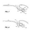
- FIG. 7is a side view illustrating speaker mount 122 rotation within loop 118 .
- the speaker(not shown), being mounted in end 702 of mount 122 that is distal from axis of rotation 508 , moves approximately vertically as mount 122 is rotated.
- This rotational movementillustrated by the double headed arrow, permits the wearer to position the speaker with respect to the ear canal as, for example, mount 122 is moved to alternate position 704 .
- the friction between loop 118 and mount 122holds mount 122 in the selected rotational position.
- mount 122is held in the selected rotational position by detents (e.g., making channel 502 polygonal rather than circular) or other conventional methods of preventing rotation.
- mount 122rotates at the distal end of loop 118 as shown in FIG. 7 .
- embodiments of eyeglasses 100 , 400are made that include different lengths and angles of loop 118 , as well as different sizes of other components (e.g., different temple lengths) to accommodate various wearers' head anatomy.
- mount 122rotates within loop 118 at various translational positions within loop 118 .
- FIG. 8is a side view illustrating an embodiment of speaker mount 122 translational movement within loop 118 .
- the speaker(not shown) is also moved.
- the weareradjusts the speaker position with respect to the ear by sliding mount 122 to, for example, alternate position 802 .
- frictionprevents unwanted mount 122 movement within loop 118 .
- Translational movementis further inhibited in other instances by using, for example, detents or other conventional methods of preventing movement.
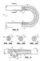
- FIG. 9is a side cutaway view of a detail of the distal end of loop 118 .
- two electrically conductive contact strips 902 , 904are inlaid into the interior surface of loop 118 .
- contact pad 510FIGS. 5 , 6
- contact pad 604FIG. 6
- contact pads 510 , 604run along channel 502
- the contact padsmaintain electrical contact with the contact strips as mount 122 rotates.
- electrical contact stripsextend along the inside of loop 118 , electrical contact is maintained as mount 122 slides within loop 118 .
- wire 912As shown in FIG. 9 , several electrical wires 906 are positioned along earstem 104 . In the embodiment shown in FIG. 9 there are three wires. Wire 908 is coupled to contact strip 902 and conducts a signal used to activate one terminal of speaker 123 . Wire 910 is coupled to contact pad 904 and carries an electrical ground potential that is used on the other terminal of speaker 123 . Wire 912 carries a signal from the microphone, as described below. The number of wires, the signals carried by the wires, and the contacts are illustrative of various methods of routing electrical signals. In some embodiments wire 912 is shielded and the shield is coupled to wire 910 .
- FIGS. 10A , 10 B, and 10 Care cross-sectional views taken at cut line 10 - 10 in FIG. 9 of various wire routing embodiments.
- wires 906are shown laid within groove 1002 channeled into earstem 104 . Wires 906 are held in groove 1002 using, for example, adhesive or a filling material (not shown) packed into the rest of the groove, or in some instances by crimping the surrounding earstem material.
- wires 906are shown routed through a hollow center channel 1004 within earstem 104 .
- wires 906are shown molded into earstem 104 (e.g., using an injection molding process). In some cases the earstem and/or frame is made from electrically conductive pieces separated by insulators, each piece carrying one or more microphone or speaker signals.
- Wire loop 706connects the speaker terminals to the wires carried in earstem 104 .
- Wire loop 706is made sufficiently large to allow rotational and translational movement of speaker housing 122 .
- the methods of providing electrical contact between the speaker and the conductors in the eyewearare illustrative of many conventional connection methods. Similar connection methods (e.g., wire loop, conductive hinge design) are used between the earstem and the eye protection portion when the earstem is hinged to the frame supporting the lenses and the microphone is mounted in the eye protection portion.
- the electrical connection designthat omits or covers a conductive wire loop, as illustrated in FIGS. 5-9 , eliminates problems such as loop breakage or loop snagging on other equipment.
- electrical components and wiring in eyeglasses 100 , 400 , and in the other system components described beloware constructed to comply with surgical theater safety standards.
- the wires 906are conventional coaxial wires having a grounded sheath to provide electromagnetic shielding from outside electromagnetic interference (EMI) from, for example, electrocautery.
- EMIelectromagnetic interference
- the earstem 104 materialprovides EMI shielding.
- electrical componentsoperate using 3 volt technology and virtually no electrical power is passed through the eyeglasses. Consequently, the signals carried in the eyeglasses, and in the other system components, do not cause EMI for nearby medical equipment.
- the shielding used to prevent outside EMIalso prevents EMI originating in the eyeglasses and other system components. Thus many conventional EMI protection configurations are used in various embodiments.
- FIG. 11is a side cutaway view showing a microphone mounting embodiment.
- Microphone 1102is shown positioned within microphone housing 124 .
- One microphone terminal 1104is coupled to wire 910 .
- Another microphone terminal 1106is coupled to wire 912 .
- Microphone case opening 1108 to the microphone pickup elementis positioned to be aligned with opening 126 in earstem 104 . Openings 126 , 1108 are oriented to pick up the sound originating from the wearer's mouth. It is known that microphone directionality is achieved by various microphone case shapes and various positions of openings allowing primary and secondary sound pressure to reach the microphone pickup element (e.g., holes positioned on opposite sides of the microphone casing). Therefore, microphone opening 1108 and earstem opening 126 are illustrative of microphone 1102 directionality that picks up the user's voice while attenuating background noise (i.e., directional microphone pointed at the wearer's mouth).
- Microphone 1102is in some cases a conventional electret condenser microphone. In other instances other microphone types are used. In some instances microphone 1102 is held in position by friction or adhesive. In other cases microphone 1102 is molded into the earstem or into the lens frame.
- FIG. 12illustrates another speaker mounting embodiment.
- Earstem 1202includes temple portion 1204 , speaker support extension 1206 , and ear support portion 1208 .
- Speaker extension 1206is an integral part of earstem 1202 .
- Speaker mount 1210includes the conventional speaker (not shown) and includes sleeve 1212 that fits over extension 1206 .
- Sleeve 1212slides along extension 1206 , as illustrated by the double headed arrow.
- two contact strips 1212 , 1214are positioned on extension 1206 .
- Contact pads(not shown) similar to pads 510 , 604 ( FIGS.
- sleeve 1212are positioned inside sleeve 1212 so that an electrical connection is established and maintained between wires in earstem 1202 and the speaker as sleeve 1212 slides.
- Other electrical contact configurationse.g., wire loop
- Unwanted sleeve 1212 movementis conventionally prevented (e.g., using friction, detents).
- mount 1210is oblong and rotates with respect to sleeve 1212 as described above with reference to loop 118 , thereby providing more precise adjustment in relation to the wearer's ear canal.
- extension 1206is bendable to position the speaker over the ear canal.
- FIG. 13illustrates yet another speaker mounting embodiment.
- speaker mount 1302is fixed to speaker support extension 1206 . Adjustment is made to the user's ear by bending extension 1206 .
- FIG. 14is a top view showing flexible electrical cord 1402 attached to an eyeglasses 100 embodiment and terminating in a conventional plug 1404 (e.g., miniature phone plug). As described below, plug 1404 is inserted into a wireless wearer unit carried by the wearer, a cellular telephone, or a personal digital assistant. As shown in FIG. 14 , cord 1402 is split and is connected to the ends of the ear support portions 120 , 121 of earstems 104 , 106 , respectively. In some instances cord 1402 is permanently attached and in other instances cord 1402 is made removable by using, for example, locking bayonet connectors of conventional design. In some instances a plastic or rubber sleeve protects the connection between cord 1402 and eyeglasses 100 . Conductors (e.g., wires) within cord 1402 carry signals for the wires (e.g., 906 as shown in FIG. 9 ) in earstems 104 , 106 .
- Conductorse.g., wires
- Cord 1402acts as a retaining neck strap to support eyeglasses 100 around the neck when the eyeglasses are removed from the head.
- the connection between cord 1402 and eyeglasses 100is made strong enough to support the weight of the eyewear.
- Cord 1402is illustrative of many eyewear retaining strap designs that may be used, such as eyewear retaining strap designs marketed under the CROAKIES trademark. Hence in some instances the connection between cord 1402 and eyeglasses 100 is not necessarily at the ends of the earstems.
- cord 1404is in one instance a conventional retaining strap and in another instance includes, for example, an antenna.
- FIG. 2shows illustrative wear of electrical connecting cord 1402 attached to eyeglasses 100 .
- the wearercarries wireless (e.g., radio) wearer unit 200 illustratively mounted on the belt.
- Wearer unit 200may be worn in various positions, although the unit is generally positioned so that cord 1402 does not interfere with the wearer's actions, for example, during surgery.
- cord 1402is coupled to eyewear 100 at positions other than the ends of the earstems (e.g., at the temples).
- wearer unit 200is combined with eyeglasses 100 , and in this case a separate neck strap may be used to support eyeglasses 100 around the wearer's neck as described above.
- the supporting frame for the combined eyeglasses and wearer unitis made large enough to accommodate the required electronics, antenna, and power supply (e.g., battery, photocells).
- power supplye.g., battery, photocells.
- connection between the eyeglasses and the wearer unitis shown as a neck strap, in some cases a single electrical cord couples the eyeglasses and the wearer unit.
- FIG. 15is a perspective view of another embodiment of eyeglasses for two-way communication.
- Eyeglasses 1502include frame 1504 supporting left and right lenses 1506 , 1508 respectively, thereby forming an eye protection portion.
- Such tintstransmit a maximum of 2 percent average ultraviolet light intensity in the 400-280 nm range, and transmit a minimum of 95 percent of average light intensity associated with brightness perception based on photopic response (e.g., 630-500 nm).
- Frame 1504further includes nose bridge portion 1509 .
- Left earstem 1510includes temple portion 1512 , support loop 1514 , and ear piece 1516 .
- Some right earstem 1518 embodimentsare a mirror image of left earstem 1510 , with only minor variations depending on microphone position.
- the microphone housing and microphone described belowmay be mounted in either one or both of earstems 1510 , 1518 , or in frame 1504 .
- the left earstem microphone position embodimentis illustrative. As shown in FIG. 15 , an upper directional opening 1520 is made in temple portion 1512 . A lower directional opening (not shown) is opposite opening 1520 .
- Frame 1504 and earstems 1510 , 1518are made of, for example, titanium or plastic.
- Speaker mount assembly 1522is mounted in support loop 1514 .
- FIG. 16is an exploded perspective view of a speaker mount assembly 1522 embodiment.
- support track 1602is positioned in support loop 1514 .
- Opposing track rails 1604define channel 1606 extending through support track 1602 .
- Track 1602is sandwiched between speaker support housing (speaker mount) 1608 and slider 1610 .
- Rib 1612 on slider 1610extends into channel 1606 such that flange 1614 rests against the outside (away from the wearer) of rails 1604 .
- Slide tab 1616 of housing 1608rests against the inside (near the wearer) of rails 1604 .
- Screw 1618extends through tab 1616 and channel 1606 , and engages slider 1610 . Tightening screw 1618 holds mount 1608 against track 1602 . Loosening screw 1618 allows the wearer to adjust housing 1608 position with respect to the ear.
- Slider cover 1620is fitted over slider 1610 on the outside of track 1602 .
- Speaker cover 1622covers speaker chamber 1624 defined in housing 1608 .
- a speaker(not shown) is positioned in chamber 1624 .
- Holes 1626extend from chamber 1624 through housing 1608 so as to provide acoustic balance for the speaker, thereby reducing unwanted sound output for the wearer.
- Holes 1628direct sound from the speaker to the ear.
- assembly 1522is adjusted so that the speaker in housing 1608 is positioned opposite the intertragial notch in the ear.
- Support portion 1514 and support assembly 1522are configured such that housing 1608 is held slightly away from the ear, although a portion of housing 1608 may touch the pinna.
- housing 1608is sized and positioned such that sound other than from the speaker reaches the concha, thereby preserving the wearer's ability to hear environmental sounds without any significant obstruction.
- the speakeris driven to produce about 80-85 dB at the acoustic standard ear reference point. Since the speaker is close to the ear, its sound causes little or no distraction to other nearby people.
- the loopconnects to wires in channel 1640 in earstem 1510 .
- the electrical connection between the speaker and conductive lines in the earstemis via a wire loop as described above.
- the loopis routed through gap 1630 in track 1602 and a small hole (not shown) in housing 1608 .
- FIG. 17is a cross-sectional view taken at cut line 17 - 17 in FIG. 15 .
- speaker 1702e.g., MWM Acoustics, LLC, of Indianapolis, Ind., part. no. DH87D5 13 mm receiver
- housing 1608e.g., 1-2 mm deep
- Acoustic loading in cavity 1704e.g., 1-2 mm deep
- cavities 1626(12 holes 1626 are used in the embodiment shown).
- Cavity 1706 in front of speaker 1702 and holes 1628are sized to prevent acoustic resonance outside the telephony bandwidth. In one embodiment, cavity 1706 is about 0.5 mm deep and there are 12 holes 1628 , each 1.0 mm in diameter.
- the speakers on earstems 1510 , 1518are driven in phase.
- FIGS. 18A and 18Bare exploded perspective views of a microphone housing portion of earstem 1510 .
- a microphone housing in earstem 1518is a mirror image.
- cavity 1802is formed in earstem 1510 into which a microphone (not shown) is positioned.
- an approximately U-shaped airspaceremains on the outside (away from the wearer) the microphone and extends to the environment via upper directional opening 1520 .
- the U-shaped airspaceis tilted slightly backward.
- microphone housing cover 1804has an approximately inverted U-shaped cavity.
- an approximately inverted U-shaped airspaceremains on the inside (near the wearer) the microphone and extends to the environment via lower directional opening 1808 .
- the inverted U-shaped airspaceis tilted slightly forward. The tilt of the U-shaped and inverted U-shaped airspaces is on a line between the microphone position in the earstem and the wearer's mouth when viewed from the side.
- the inside-outside offset of lower directional opening 1808 and upper directional opening 1520is also on a line between the microphone position and the wearer's mouth when viewed from the front.
- the microphone positioned in cavity 1802is a gradient microphone, responsive to differences between sound pressures on opposing sides, and directionality is established towards the wearer's mouth.
- FIGS. 19A and 19Billustrate microphone directionality in embodiments of eyeglasses 1502 .
- lower directional opening 1808provides a primary pickup zone 1902 towards the wearer's mouth.
- Upper directional opening 1520provides a secondary pickup zone 1904 up and away from the wearer in a direction from which little sound originates.
- FIG. 19Bshows another view of zones 1902 , 1904 .
- FIG. 19Balso shows a benefit of using two microphones symmetrically mounted on the eyeglasses.
- Primary pickup zones 1902 and 1906may be additive, providing an additional boost over sounds detected in secondary pickup zones 1904 and 1908 . Thus pickup of the wearer's voice is further enhanced while unwanted background noise is reduced.
- the one or more microphonesmay be used in combination with conventional noise cancellation software which is easily modified for use in these embodiments.
- wires (not shown) for the microphoneare positioned in channel 1810 ( FIG. 18A ) and pass through notch 1812 ( FIG. 18B ) in cover 1804 .
- the positive wire leading to the microphoneis shielded and, in some instances, coupled to ground and/or the negative speaker terminal.
- wires for the speaker and microphoneare fitted into channel 1640 defined in earstem 1510 .
- Wires in eyeglasses 1502are coupled to cord 1402 as described above.
- FIG. 20is a cross-sectional view taken at cut line 20 - 20 in FIG. 15 .
- microphone 2002e.g., MWM Acoustics part no. NM4518
- cavity 1802FIG. 18A
- Openings 1520 and 1808are about 1.0 mm wide.
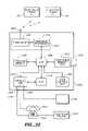
- FIG. 21is a diagrammatic view of a communication system using eyeglasses configured for two-way communication (e.g., eyeglasses 100 , 1502 ).
- the systemis not limited to use with embodiments of the eyeglasses, and other head-mounted communication apparatus 2101 (e.g., conventional head-mounted video displays) may be coupled to wearer unit 200 .
- wearer unit 200communicates with base station 2102 using the BLUETOOTH wireless protocol to carry information in one or more channels (e.g., audio, data) via signals 2104 .
- Either unit 200 or base station 2102may be designated as the master BLUETOOTH device.
- Base station 2102may be any BLUETOOTH-capable device such as one designed for a specific application (e.g., hospital use), a desktop or laptop computer, or small personal digital assistant. Embodiments are not restricted to BLUETOOTH, and other wireless protocols may be used.
- base station 2102is coupled via CODEC port 2106 to conventional telephone receiver 2108 .
- Receiver 2108may be coupled to various systems 2110 , such as a POTS line, a PBX line, or a secure web server in a hospital network.
- Base station 2102may be coupled to systems 2110 via port 2112 without passing through receiver 2108 .
- a personwearing a two-way communication device (e.g., eyeglasses 100 , 400 , 1502 ) may, for example, confer with another person (e.g., a pathologist), receive data (e.g., patient records, diagnostic images).
- a two-way communication devicee.g., eyeglasses 100 , 400 , 1502
- another persone.g., a pathologist
- receive datae.g., patient records, diagnostic images
- Base station 2102may also be coupled to various equipment 2114 (e.g., medical devices in an operating theater) so as to exchange data and/or control commands.
- the wearerspeaks a voice request for data (e.g., “insuflator, pressure”), the request is relayed to the insuflator which in response outputs pressure data that is passed back to the wearer who receives the data as a synthesized voice (e.g., “insuflator, 200 millimeters of mercury”).
- the surgeonmay speak a command to control a device (e.g., “insuflator, increase pressure 10 millimeters of mercury”).
- the controlled devicemay request confirmation to prevent errors.
- a surgeonmakes a voice command to adjust the white color balance of a monitor displaying an image from a surgical camera (e.g., endoscope).
- the signal processing required for voice activated data reception and command and controlmay be carried out using one or more digital signal processors (DSPs) executing software (e.g., conventional voice recognition and synthesis software, which is easily modified for use in specific applications in light of this specification).
- DSPsdigital signal processors
- softwaree.g., conventional voice recognition and synthesis software, which is easily modified for use in specific applications in light of this specification.
- Devices 2114are also illustrative of an audio/video (AV) recorder.
- the wearernarrates an audio recording using eyeglasses 100 during a video recording of, for example, a surgical procedure.
- the surgeon's narrationis output by base station 2102 as an audio input to the AV recorder.
- equipment 2114is BLUETOOTH capable and wearer unit 200 communicates directly with equipment 2114 via signals 2116 without using base station 2102 (i.e., a BLUETOOTH-capable device 2114 need not be coupled to a base station).
- device 2114is a terminal supplying patient information (e.g., records, diagnostic images).
- patient informatione.g., records, diagnostic images.
- specific informatione.g., name, general diagnosis
- a patient associated with device 2114e.g., a patient lying in a hospital bed near device 2114
- the physicianmay speak commands so as to receive additional information (e.g., recent laboratory results, x-ray images) about that particular patient.
- FIG. 22is a diagrammatic view of functional blocks in an illustrative wearer unit 200 .
- the wearer unit 200 embodiment shown in FIG. 22includes transceiver 2202 , baseband processor 2204 , digital signal processor (DSP) 2206 , program memory 2208 , eyewear interface unit 2210 , and removable memory unit 2212 .
- Transceiver 2202 and baseband processor 2204 togetherare included in radio module 2214 .
- wearer unit 200is constructed using 3.3 volt technology electronics.
- Transceiver 2202transmits signals to and receives signals from, for example, base station 2102 and/or devices 2114 via antenna 2216 which is coupled to transceiver 2202 .
- transceiver 2202is a conventional 2.4 gigahertz (GHz) transceiver such as ones used in Digital Enhanced Cordless Telecommunications (DECT) systems and cordless telephones.
- GHzgigahertz
- Baseband processor 2204is, for example, a conventional BLUETOOTH baseband processor with software and/or firmware that manages the hardware portion of the BLUETOOTH interface protocol.
- Radio module 2214is typically sold as a complete package and is available from various vendors such as Texas Instruments Incorporated headquartered in the United States, Koninklijke Philips Electronics N.V. (Royal Philips Electronics) headquartered in the Netherlands.
- the use of BLUETOOTH communication protocolis illustrative of other protocols.
- DSP 2206processes the BLUETOOTH stack software and applications software such as echo cancellation, voice recognition, command and control, speech compression, and speech synthesis.
- DSP 2206is a Texas Instruments DSP part no. TMS320VC5402PGE100.
- DSP 2206executes noise reduction software (e.g., echo canceling) that improves the sound quality originating at the one or more microphones mounted on the eyewear.
- Noise cancellation softwareis commercially available (e.g., from Texas Instruments, Incorporated), and modification of such software for this application is easily accomplished in light of this-disclosure.
- Positioning DSP 2206 in wearer unit 200allows the wearer unit to be customized to the wearer.
- each wearer unit 200is programmed with a unique identification code (e.g., BLUETOOTH address). Hence the unique code also identifies a particular wearer associated with the wearer unit.
- Devices receiving signals from the wearer unitalso receive the wearer unit's identification number.
- Devices sending information to a particular wearer unitaddress the sent information by using the identification number.
- each wearer unitis customized to recognize the wearer's voice and to recognize particular voice commands. For example, voice recognition software executed by DSP 2206 discriminates between the wearer's voice and other nearby voices.
- command and control software executed by DSP 2206recognizes a command customized to the wearer (e.g., “call home” to initiate a telephone call to the wearer's home).
- a command customized to the wearere.g., “call home” to initiate a telephone call to the wearer's home.
- some of these DSP functionsmay be carried out by a DSP in a base station, as described below.
- Memory 2208is coupled to DSP 1506 and stores both software used to process the BLUETOOTH program stack and application program software.
- Memory 1508is, in one instance, conventional flash memory. The use of flash memory allows software upgrades to be made in the field. Other memory types or combinations of types are used for memory 2208 in other embodiments.
- Eyewear interface unit 2210is coupled to DSP 2206 and provides an analog interface (e.g., CODEC) between DSP 2206 and the microphone and speakers in eyeglasses 100 , 400 , 1502 .
- Plug 1404is inserted into terminal 2218 .
- interface unit 2210provides a digital interface.
- a separate processornot shown; e.g., a programmable logic device (PLD) as described below
- PLDprogrammable logic device
- removable memory unit 2212is coupled to DSP 2206 .
- Memory unit 2212is in some embodiments a conventional flash memory card read/write device that receives removable memory module 2215 (e.g., compact flash memory card)
- Module 2215stores information from DSP 2206 (e.g., digitized recordings of the wearer's speech) and/or stores information used by DSP 2206 (e.g., upgrades for software stored in memory 2208 ).
- the audio information from the microphone in the eyeglassesis compressed by DSP using conventional compression technology for storage on module 2215 .
- Various embodimentsstore digitized audio in various file formats (e.g., .wav, .mp3) to comply with the device receiving the recorded audio.
- wearer unit 2120omits removable memory unit 2214 , DSP 2206 , and memory 2208 .
- Interface unit 2210couples the microphone and speakers in, for example, eyeglasses 100 with radio module 2214 .
- Wearer unit 2120hangs at the bottom of the neck strap. In some instances unit 2120 may be made small enough to be mounted directly on an embodiment of eyeglasses 100 .
- FIG. 23is a diagrammatic view of an illustrative base station embodiment 2300 .
- base station 2300includes transceiver 2302 , baseband processor 2304 , DSP 2306 , program memory 2308 , interface unit 2310 , and removable memory unit 2312 .
- Transceiver 2302 and baseband processor 2304 togetherare included in radio module 2314 .
- Base station 2300also includes PLD 2318 and user control unit 2320 .
- transceivers 2202 , 2302 , baseband processors 2204 , 2304 , radio modules 2214 , 2314 , DSPs 2206 , 2306 , program memories 2208 , 2308 , removable memory units 2212 , 2312 , removable memory modules 2215 , 2315 , and antennas 2216 , 2316are the same or are substantially similar. In some cases the removable memory units 2212 and/or 2312 are omitted.
- PLD 2318e.g., Lattice Semiconductor Corporation part no. ISPLSI2096VL100LT128, provides an asynchronous port (e.g., Host Computer Interface (HCI) port) in addition to synchronous ports (e.g., Synchronous Communication Oriented (SCO) port) provided by DSP 2306 .
- HCIHost Computer Interface
- synchronous portse.g., Synchronous Communication Oriented (SCO) port
- User control unit 2320allows a person to route information from any input to any output in base station 2300 .
- a call incoming from telephone system 2322arrives at telephone 2324 (located, for example, in an operating theater).
- the callis routed through ports 2328 and 2330 to handset 2326 .
- the person answering the calle.g., a nurse
- the wearerthen conducts the call using the speakers and microphone in the eyeglasses.
- Another wearermay be switched into the conversation by pressing another control unit 2320 button.
- An outgoing callmay be made using similar actions to associate an eyeglasses wearer with telephone 2324 and then dialing a desired number.
- a wearermay dial a number using voice commands for hands-free dialing (e.g., speaks the command “dial telephone” and then speaks the numbers).
- the base stationis assigned a particular telephone number and the inbound caller is presented with a menu (e.g., synthesized voice) of BLUETOOTH addressees currently communicating with the base station (each BLUETOOTH address being associated with a particular name). The caller selects the called party from the menu.
- Device 2332 coupled to port 2334is illustrative of other devices and systems 2110 , 2114 described above with reference to FIG. 21 .
- DSPs 2206 , 2306 in wearer unit 200 and/or base station 2102provide digital audio recording capability.
- the wearer's digitized voiceis recorded by one of the removable memory units 2212 , 2312 onto removable memory module 2215 , 2315 , respectively.
- the surgeon dictating surgical notesmay do so during the surgery or afterwards.
- Providing the wearer hands-free dictation capability during surgeryadvantageously saves time since the wearer does not have to spend time after surgery dictating notes. Or, the wearer may choose to dictate notes after each surgery.
- Providing the removable memory unit in wearer unit 200allows the wearer to move outside base station communication range and still complete dictation. In situations in which base station 2102 communicates with several eyeglasses 100 , multiple removable memory units 2312 are provided to allow each wearer to record on a unique memory module 2315 .
- the wearer's dictationis recorded on module 2215 or module 2315
- various methodsare used to transcribe the recorded dictation. In one instance the wearer forwards the removed module to a transcription service. In another instance the wearer inserts the removed module 2215 , 2315 into a corresponding memory module reader and forwards the recorded files to a transcription service via, for example, email. In still another instance, the wearer inserts the memory module into a reader coupled to the wearer's personal computer.
- Transcription software executed by the wearer's personal computercreates a text file of the recorded dictation.
- transcription module including medical vocabularyavailable from Computer Programs & Systems, Inc., Mobile, Ala.
- transcription module available from L&H Dragon Systems, Inc., Newton, Mass.creates a text file of the recorded dictation.
- the wearer's voiceis transmitted to a remote location (e.g., remote transcription service, transcription-capable computer located elsewhere in the hospital).
- the received dictationis transcribed at the remote location into a text file.
- the text file, or a printout of the text fileis made available to the surgeon immediately after completing surgery. For example, the surgeon enters the surgeon's lounge, prints the transcribed surgical notes dictation, and edits the transcript.
- One or both removable memory units 2212 , 2312may be omitted from embodiments in which the wearer's voice is routed in real time to a remote transcription system.
- a transcription text fileis created, either by a service or by the wearer's computer
- the weareredits the text file transcription using a word processing program executed by the personal computer.
- the userthen adds an electronic signature to the edited text file to signify approval (a legal requirement for surgical records in many jurisdictions) and forwards the approved file to a hospital record storage area.
- the wearerprints a copy of the transcribed text and edits the printed copy.
- Communication devicesconfigured to operate using the BLUETOOTH protocol periodically poll for other BLUETOOTH devices entering communication range.
- device profilesare defined (e.g., identifying a device as a headset). Accordingly, if one BLUETOOTH device enters communication range of a second BLUETOOTH device, each BLUETOOTH device will receive information regarding the communication capability of the other.
- a communication link between the eyeglasses and base stationis automatically established. In other instances the communication link between the eyeglasses and base station is controlled to prevent interference when multiple base stations are in close proximity.
- FIG. 24is a diagrammatic plan view showing two illustrative operating theaters 2402 a and 2402 b .
- Base station 2404 ais located in theater 2402 a and is connected to telephone 2406 a as described above.
- base station 2404 bis located in theater 2402 b and is connected to telephone 2406 b .
- Telephones 2406 a , 2406 bare illustrative of the various possible connections for the base stations.
- a person 2408 wearing the two-way communication eyeglasses coupled to a wearer unitis within range of both base stations 2404 a , 2404 b when located in theater 2402 a .
- person 2408registers his or her wearer unit with base station 2404 a .
- Such registrationis accomplished by, for example, establishing an electrical connection (using, e.g., conventional pogo prongs) between the BLUETOOTH circuits in the wearer unit and base station.
- registrationis accomplished by sending a particular registration code between the BLUETOOTH circuits via a wireless signal.
- Registrationincludes the wearer unit and/or eyeglasses sending the unique identification code to the base station.
- the base stationis aware of the particular registered wearer unit's identity.
- wearersmay register with a single base station.
- the number of wearers registered with a particular base stationis limited by the number of simultaneous communication channels (one channel per wearer for voice and, where applicable, data) supported by that particular base station.
- registration with base station 2404 aties the wearer(s) to the telephone number(s) associated with telephone 2406 a.
- wearer's registrationis automatically terminated if the wearer moves outside of the range of the registered base station.
- communicating unitsare continuously polled to determine if they are within range.
- wearer unit 200issues a command to the registered base station to terminate registration.
- FIG. 24shows wearer 2408 exiting theater 2402 a and entering theater 2402 b , yet remaining within range of base station 2404 a .
- wearer unit 200instructs base station 2404 a (or all base stations with which wearer unit 200 is registered) to terminate registration.
- wearer 2408terminates registration with base station 2404 a prior to leaving theater 2402 a by issuing and instruction (e.g., pressing a button on the base station user control).
- FIG. 25is a diagrammatic view illustrating eyewear 100 coupled via neck strap 1402 to a conventional communications device 2502 such as a cellular telephone or personal digital assistant (e.g., VISOR PDA manufactured by Handspring, Inc., Mountain View, Calif., which in some cases includes cellular telephone capability).
- a conventional communications device 2502such as a cellular telephone or personal digital assistant (e.g., VISOR PDA manufactured by Handspring, Inc., Mountain View, Calif., which in some cases includes cellular telephone capability).
- Conventional baseband processing module 2504e.g., plug-in BLUETOOTH module
- Signals 2506carry audio and data between module 2004 and base station 2508 as described above. If device 2502 omits a DSP that is programmed to carry out a desired function as described above, that function is carried out by the DSP in base station 2508 .
- FIG. 25also illustrates that eyeglasses 100 are used in some instances to facilitate hands-free operation of other devices.
- communication between device 2502e.g., cellular telephone
- cellular antenna 2510are via signals 2512 .
- Antenna 2510is coupled to mobile switching center 2514 which, in turn, is coupled to the public switched telephone system (PSTN) (not shown).
- PSTNpublic switched telephone system
Landscapes
- Physics & Mathematics (AREA)
- Health & Medical Sciences (AREA)
- Engineering & Computer Science (AREA)
- Signal Processing (AREA)
- Otolaryngology (AREA)
- Computer Networks & Wireless Communication (AREA)
- Acoustics & Sound (AREA)
- General Health & Medical Sciences (AREA)
- General Physics & Mathematics (AREA)
- Ophthalmology & Optometry (AREA)
- Optics & Photonics (AREA)
- Eyeglasses (AREA)
Abstract
Description
Claims (16)
Priority Applications (1)
| Application Number | Priority Date | Filing Date | Title |
|---|---|---|---|
| US09/972,342US7313246B2 (en) | 2001-10-06 | 2001-10-06 | Information system using eyewear for communication |
Applications Claiming Priority (1)
| Application Number | Priority Date | Filing Date | Title |
|---|---|---|---|
| US09/972,342US7313246B2 (en) | 2001-10-06 | 2001-10-06 | Information system using eyewear for communication |
Publications (2)
| Publication Number | Publication Date |
|---|---|
| US20030068057A1 US20030068057A1 (en) | 2003-04-10 |
| US7313246B2true US7313246B2 (en) | 2007-12-25 |
Family
ID=29216405
Family Applications (1)
| Application Number | Title | Priority Date | Filing Date |
|---|---|---|---|
| US09/972,342Expired - LifetimeUS7313246B2 (en) | 2001-10-06 | 2001-10-06 | Information system using eyewear for communication |
Country Status (1)
| Country | Link |
|---|---|
| US (1) | US7313246B2 (en) |
Cited By (52)
| Publication number | Priority date | Publication date | Assignee | Title |
|---|---|---|---|---|
| US20050195996A1 (en)* | 2004-03-05 | 2005-09-08 | Dunn William F. | Companion microphone system and method |
| US20060197907A1 (en)* | 2002-07-26 | 2006-09-07 | James Jannard | Electronic eyewear with hands-free operation |
| US20080090679A1 (en)* | 1999-01-05 | 2008-04-17 | Browne H Lee | Video instructional system and method for teaching motor skills |
| US20080178435A1 (en)* | 2007-01-29 | 2008-07-31 | Lite-On Technology Corporation | Personal audio listening device |
| US20080232632A1 (en)* | 2007-03-23 | 2008-09-25 | Lite-On Technology Corporation | Ear hooked earphone |
| US20090091838A1 (en)* | 2007-10-09 | 2009-04-09 | Thomas Zaloum | Eyewear display and media device interconnection system |
| US20090123000A1 (en)* | 2006-05-03 | 2009-05-14 | Wright Kenneth A | Wearable personal sound delivery apparatus |
| US20100045928A1 (en)* | 2008-08-25 | 2010-02-25 | Tri-Specs, Inc. | Fashion eyewear frame that houses circuitry to effect wireless audio communication while providing extraneous background noise cancellation capability |
| US20100166209A1 (en)* | 2008-12-31 | 2010-07-01 | Etymotic Research, Inc. | Companion microphone system and method |
| US20110247627A1 (en)* | 2008-11-27 | 2011-10-13 | Teijin Pharma Limited | Wearing tool for breathing mask, and breathing mask |
| US8184983B1 (en) | 2010-11-12 | 2012-05-22 | Google Inc. | Wireless directional identification and subsequent communication between wearable electronic devices |
| US8467133B2 (en) | 2010-02-28 | 2013-06-18 | Osterhout Group, Inc. | See-through display with an optical assembly including a wedge-shaped illumination system |
| US8472120B2 (en) | 2010-02-28 | 2013-06-25 | Osterhout Group, Inc. | See-through near-eye display glasses with a small scale image source |
| US8477425B2 (en) | 2010-02-28 | 2013-07-02 | Osterhout Group, Inc. | See-through near-eye display glasses including a partially reflective, partially transmitting optical element |
| US8482859B2 (en) | 2010-02-28 | 2013-07-09 | Osterhout Group, Inc. | See-through near-eye display glasses wherein image light is transmitted to and reflected from an optically flat film |
| US8488246B2 (en) | 2010-02-28 | 2013-07-16 | Osterhout Group, Inc. | See-through near-eye display glasses including a curved polarizing film in the image source, a partially reflective, partially transmitting optical element and an optically flat film |
| US8550621B2 (en) | 2006-12-14 | 2013-10-08 | Oakley, Inc. | Wearable high resolution audio visual interface |
| US8744113B1 (en)* | 2012-12-13 | 2014-06-03 | Energy Telecom, Inc. | Communication eyewear assembly with zone of safety capability |
| US8787970B2 (en) | 2001-06-21 | 2014-07-22 | Oakley, Inc. | Eyeglasses with electronic components |
| US8814691B2 (en) | 2010-02-28 | 2014-08-26 | Microsoft Corporation | System and method for social networking gaming with an augmented reality |
| US20140321661A1 (en)* | 2013-04-25 | 2014-10-30 | Emmanuel Adedolapo Alao | Wireless headband audio player |
| US20150020815A1 (en)* | 2013-07-17 | 2015-01-22 | Pamela Gabriel | Protective Mask with Imbedded Functionality |
| US9091851B2 (en) | 2010-02-28 | 2015-07-28 | Microsoft Technology Licensing, Llc | Light control in head mounted displays |
| US9097890B2 (en) | 2010-02-28 | 2015-08-04 | Microsoft Technology Licensing, Llc | Grating in a light transmissive illumination system for see-through near-eye display glasses |
| US9097891B2 (en) | 2010-02-28 | 2015-08-04 | Microsoft Technology Licensing, Llc | See-through near-eye display glasses including an auto-brightness control for the display brightness based on the brightness in the environment |
| US9128281B2 (en) | 2010-09-14 | 2015-09-08 | Microsoft Technology Licensing, Llc | Eyepiece with uniformly illuminated reflective display |
| US9129295B2 (en) | 2010-02-28 | 2015-09-08 | Microsoft Technology Licensing, Llc | See-through near-eye display glasses with a fast response photochromic film system for quick transition from dark to clear |
| US9134534B2 (en) | 2010-02-28 | 2015-09-15 | Microsoft Technology Licensing, Llc | See-through near-eye display glasses including a modular image source |
| US9182596B2 (en) | 2010-02-28 | 2015-11-10 | Microsoft Technology Licensing, Llc | See-through near-eye display glasses with the optical assembly including absorptive polarizers or anti-reflective coatings to reduce stray light |
| US9223134B2 (en) | 2010-02-28 | 2015-12-29 | Microsoft Technology Licensing, Llc | Optical imperfections in a light transmissive illumination system for see-through near-eye display glasses |
| US9229227B2 (en) | 2010-02-28 | 2016-01-05 | Microsoft Technology Licensing, Llc | See-through near-eye display glasses with a light transmissive wedge shaped illumination system |
| US9285589B2 (en) | 2010-02-28 | 2016-03-15 | Microsoft Technology Licensing, Llc | AR glasses with event and sensor triggered control of AR eyepiece applications |
| US9341843B2 (en) | 2010-02-28 | 2016-05-17 | Microsoft Technology Licensing, Llc | See-through near-eye display glasses with a small scale image source |
| US9366862B2 (en) | 2010-02-28 | 2016-06-14 | Microsoft Technology Licensing, Llc | System and method for delivering content to a group of see-through near eye display eyepieces |
| USD763828S1 (en) | 2015-06-11 | 2016-08-16 | Oakley, Inc. | Headwear accessory |
| USD764568S1 (en) | 2015-06-11 | 2016-08-23 | Oakley, Inc. | Eyeglass |
| US20160360146A1 (en)* | 2015-06-02 | 2016-12-08 | Taser International, Inc. | User-Worn Recording System |
| US9619201B2 (en) | 2000-06-02 | 2017-04-11 | Oakley, Inc. | Eyewear with detachable adjustable electronics module |
| US9648437B2 (en) | 2009-08-03 | 2017-05-09 | Imax Corporation | Systems and methods for monitoring cinema loudspeakers and compensating for quality problems |
| US9720258B2 (en) | 2013-03-15 | 2017-08-01 | Oakley, Inc. | Electronic ornamentation for eyewear |
| US9720260B2 (en) | 2013-06-12 | 2017-08-01 | Oakley, Inc. | Modular heads-up display system |
| US9759917B2 (en) | 2010-02-28 | 2017-09-12 | Microsoft Technology Licensing, Llc | AR glasses with event and sensor triggered AR eyepiece interface to external devices |
| US9864211B2 (en) | 2012-02-17 | 2018-01-09 | Oakley, Inc. | Systems and methods for removably coupling an electronic device to eyewear |
| US10180572B2 (en) | 2010-02-28 | 2019-01-15 | Microsoft Technology Licensing, Llc | AR glasses with event and user action control of external applications |
| US10222617B2 (en) | 2004-12-22 | 2019-03-05 | Oakley, Inc. | Wearable electronically enabled interface system |
| US10530915B2 (en) | 2008-09-30 | 2020-01-07 | Apple Inc. | Head-mounted display apparatus for retaining a portable electronic device with display |
| US10539787B2 (en) | 2010-02-28 | 2020-01-21 | Microsoft Technology Licensing, Llc | Head-worn adaptive display |
| USD885559S1 (en) | 2019-03-04 | 2020-05-26 | The Smartmask Llc | Respiratory mask |
| US10786695B2 (en) | 2013-07-17 | 2020-09-29 | The Smartmask Llc | Protective respiratory mask with electronic system |
| US10860100B2 (en) | 2010-02-28 | 2020-12-08 | Microsoft Technology Licensing, Llc | AR glasses with predictive control of external device based on event input |
| US11340464B2 (en)* | 2018-09-27 | 2022-05-24 | Seiko Epson Corporation | Head-mounted display apparatus |
| US11350196B2 (en)* | 2016-08-22 | 2022-05-31 | Mentor Acquisition One, Llc | Speaker systems for head-worn computer systems |
Families Citing this family (115)
| Publication number | Priority date | Publication date | Assignee | Title |
|---|---|---|---|---|
| USD523461S1 (en) | 1906-12-02 | 2006-06-20 | Oakley, Inc. | Eyeglass component |
| US7278734B2 (en) | 2000-06-02 | 2007-10-09 | Oakley, Inc. | Wireless interactive headset |
| US7150526B2 (en) | 2000-06-02 | 2006-12-19 | Oakley, Inc. | Wireless interactive headset |
| US7461936B2 (en) | 2000-06-02 | 2008-12-09 | Oakley, Inc. | Eyeglasses with detachable adjustable electronics module |
| US6325507B1 (en)* | 2000-06-02 | 2001-12-04 | Oakley, Inc. | Eyewear retention system extending across the top of a wearer's head |
| US6729726B2 (en)* | 2001-10-06 | 2004-05-04 | Stryker Corporation | Eyewear for hands-free communication |
| JP3532544B2 (en)* | 2001-10-30 | 2004-05-31 | 株式会社テムコジャパン | Transmitter / receiver for mounting a face or cap strap |
| US7380936B2 (en) | 2003-10-09 | 2008-06-03 | Ipventure, Inc. | Eyeglasses with a clock or other electrical component |
| US7806525B2 (en) | 2003-10-09 | 2010-10-05 | Ipventure, Inc. | Eyeglasses having a camera |
| US8109629B2 (en) | 2003-10-09 | 2012-02-07 | Ipventure, Inc. | Eyewear supporting electrical components and apparatus therefor |
| US8465151B2 (en) | 2003-04-15 | 2013-06-18 | Ipventure, Inc. | Eyewear with multi-part temple for supporting one or more electrical components |
| US7922321B2 (en) | 2003-10-09 | 2011-04-12 | Ipventure, Inc. | Eyewear supporting after-market electrical components |
| US20050230596A1 (en)* | 2004-04-15 | 2005-10-20 | Howell Thomas A | Radiation monitoring system |
| US7581833B2 (en) | 2003-10-09 | 2009-09-01 | Ipventure, Inc. | Eyewear supporting after-market electrical components |
| US7500747B2 (en) | 2003-10-09 | 2009-03-10 | Ipventure, Inc. | Eyeglasses with electrical components |
| US7792552B2 (en)* | 2003-04-15 | 2010-09-07 | Ipventure, Inc. | Eyeglasses for wireless communications |
| US7255437B2 (en) | 2003-10-09 | 2007-08-14 | Howell Thomas A | Eyeglasses with activity monitoring |
| US7192136B2 (en)* | 2003-04-15 | 2007-03-20 | Howell Thomas A | Tethered electrical components for eyeglasses |
| US7760898B2 (en) | 2003-10-09 | 2010-07-20 | Ip Venture, Inc. | Eyeglasses with hearing enhanced and other audio signal-generating capabilities |
| US7500746B1 (en) | 2004-04-15 | 2009-03-10 | Ip Venture, Inc. | Eyewear with radiation detection system |
| US7257372B2 (en)* | 2003-09-30 | 2007-08-14 | Sony Ericsson Mobile Communications Ab | Bluetooth enabled hearing aid |
| US10345625B2 (en) | 2003-10-09 | 2019-07-09 | Ingeniospec, Llc | Eyewear with touch-sensitive input surface |
| US11513371B2 (en) | 2003-10-09 | 2022-11-29 | Ingeniospec, Llc | Eyewear with printed circuit board supporting messages |
| US11630331B2 (en) | 2003-10-09 | 2023-04-18 | Ingeniospec, Llc | Eyewear with touch-sensitive input surface |
| US10310296B2 (en) | 2003-10-09 | 2019-06-04 | Ingeniospec, Llc | Eyewear with printed circuit board |
| US7438410B1 (en)* | 2003-10-09 | 2008-10-21 | Ip Venture, Inc. | Tethered electrical components for eyeglasses |
| US7677723B2 (en)* | 2003-10-09 | 2010-03-16 | Ipventure, Inc. | Eyeglasses with a heart rate monitor |
| USD547346S1 (en) | 2004-03-09 | 2007-07-24 | V.I.O., Inc. | Camera |
| US20060055786A1 (en)* | 2004-03-09 | 2006-03-16 | Viosport | Portable camera and wiring harness |
| US7548833B2 (en)* | 2004-03-25 | 2009-06-16 | Siemens Building Technologies, Inc. | Method and apparatus for graphical display of a condition in a building system with a mobile display unit |
| US11829518B1 (en) | 2004-07-28 | 2023-11-28 | Ingeniospec, Llc | Head-worn device with connection region |
| US8337013B2 (en)* | 2004-07-28 | 2012-12-25 | Ipventure, Inc. | Eyeglasses with RFID tags or with a strap |
| US11644693B2 (en) | 2004-07-28 | 2023-05-09 | Ingeniospec, Llc | Wearable audio system supporting enhanced hearing support |
| CN101015130A (en)* | 2004-09-10 | 2007-08-08 | 兰斯·弗里德 | Waterproof and Shockproof Music Player |
| US20060227675A1 (en)* | 2004-09-10 | 2006-10-12 | Lance Fried | Wetsuit with integrated pocket for audio/video device |
| US20070036376A1 (en)* | 2004-09-10 | 2007-02-15 | Lance Fried | Earphones |
| US20070157457A1 (en)* | 2004-09-10 | 2007-07-12 | Lance Fried | Assembly Method and Machinery for Waterproof Testing of Electronic Devices |
| US20060087924A1 (en)* | 2004-10-22 | 2006-04-27 | Lance Fried | Audio/video portable electronic devices providing wireless audio communication and speech and/or voice recognition command operation |
| US11852901B2 (en) | 2004-10-12 | 2023-12-26 | Ingeniospec, Llc | Wireless headset supporting messages and hearing enhancement |
| CN103941426B (en) | 2004-11-19 | 2016-05-25 | 奥克利有限公司 | Wireless interactive headset |
| USD514613S1 (en) | 2004-12-02 | 2006-02-07 | Oakley, Inc. | Eyeglass and eyeglass components |
| USD538836S1 (en) | 2005-02-11 | 2007-03-20 | Oakley, Inc. | Eyewear module |
| US9943372B2 (en)* | 2005-04-18 | 2018-04-17 | M.S.T. Medical Surgery Technologies Ltd. | Device having a wearable interface for improving laparoscopic surgery and methods for use thereof |
| US7956888B2 (en) | 2005-06-22 | 2011-06-07 | Ge Inspection Technologies, Lp | Remote video inspection system integrating audio communication functionality |
| USD548767S1 (en) | 2005-08-22 | 2007-08-14 | Oakley, Inc. | Eyeglass and eyeglass components |
| US11733549B2 (en) | 2005-10-11 | 2023-08-22 | Ingeniospec, Llc | Eyewear having removable temples that support electrical components |
| US12044901B2 (en) | 2005-10-11 | 2024-07-23 | Ingeniospec, Llc | System for charging embedded battery in wireless head-worn personal electronic apparatus |
| AU2015201658B2 (en)* | 2006-01-06 | 2017-01-05 | Abreu, Marcio Marc Aurelio Martins MR | A wearable electronic system and support structure for a wearable electronic device |
| US7543934B2 (en)* | 2006-09-20 | 2009-06-09 | Ipventures, Inc. | Eyeglasses with activity monitoring and acoustic dampening |
| US20080097176A1 (en)* | 2006-09-29 | 2008-04-24 | Doug Music | User interface and identification in a medical device systems and methods |
| CN101632033B (en)* | 2007-01-12 | 2013-07-31 | 寇平公司 | Head-mounted monocular display device |
| US9217868B2 (en)* | 2007-01-12 | 2015-12-22 | Kopin Corporation | Monocular display device |
| CA2579926A1 (en)* | 2007-02-28 | 2008-08-28 | Ttg Systems Incorporated | System and method for capturing steps of a procedure |
| US8855719B2 (en)* | 2009-05-08 | 2014-10-07 | Kopin Corporation | Wireless hands-free computing headset with detachable accessories controllable by motion, body gesture and/or vocal commands |
| US9116340B2 (en) | 2007-05-14 | 2015-08-25 | Kopin Corporation | Mobile wireless display for accessing data from a host and method for controlling |
| US8825468B2 (en)* | 2007-07-31 | 2014-09-02 | Kopin Corporation | Mobile wireless display providing speech to speech translation and avatar simulating human attributes |
| USD577370S1 (en) | 2007-11-12 | 2008-09-23 | Lance Fried | MP3 player |
| WO2009120984A1 (en) | 2008-03-28 | 2009-10-01 | Kopin Corporation | Handheld wireless display device having high-resolution display suitable for use as a mobile internet device |
| US8355671B2 (en)* | 2008-01-04 | 2013-01-15 | Kopin Corporation | Method and apparatus for transporting video signal over Bluetooth wireless interface |
| EP2254345A4 (en)* | 2008-03-17 | 2012-08-29 | Temco Japan | Bone conduction speaker and listening device using same |
| US8831954B2 (en)* | 2008-05-08 | 2014-09-09 | Nuance Communications, Inc. | Localizing the position of a source of a voice signal |
| US9400390B2 (en) | 2014-01-24 | 2016-07-26 | Osterhout Group, Inc. | Peripheral lighting for head worn computing |
| US9715112B2 (en) | 2014-01-21 | 2017-07-25 | Osterhout Group, Inc. | Suppression of stray light in head worn computing |
| WO2010129679A1 (en) | 2009-05-08 | 2010-11-11 | Kopin Corporation | Remote control of host application using motion and voice commands |
| US8665177B2 (en)* | 2010-02-05 | 2014-03-04 | Kopin Corporation | Touch sensor for controlling eyewear |
| US8706170B2 (en) | 2010-09-20 | 2014-04-22 | Kopin Corporation | Miniature communications gateway for head mounted display |
| US10013976B2 (en) | 2010-09-20 | 2018-07-03 | Kopin Corporation | Context sensitive overlays in voice controlled headset computer displays |
| US8736516B2 (en) | 2010-09-20 | 2014-05-27 | Kopin Corporation | Bluetooth or other wireless interface with power management for head mounted display |
| US9377862B2 (en) | 2010-09-20 | 2016-06-28 | Kopin Corporation | Searchlight navigation using headtracker to reveal hidden or extra document data |
| US9316827B2 (en) | 2010-09-20 | 2016-04-19 | Kopin Corporation | LifeBoard—series of home pages for head mounted displays (HMD) that respond to head tracking |
| US8862186B2 (en) | 2010-09-21 | 2014-10-14 | Kopin Corporation | Lapel microphone micro-display system incorporating mobile information access system |
| GB201019077D0 (en)* | 2010-11-11 | 2010-12-29 | Benmore Ventures Ltd | Electronic display device |
| CN109116985A (en) | 2011-05-10 | 2019-01-01 | 寇平公司 | The method that control information is shown |
| US8939769B2 (en)* | 2011-07-11 | 2015-01-27 | Nike, Inc. | Multi-sensory manipulation |
| US9405135B2 (en) | 2011-09-15 | 2016-08-02 | Ipventure, Inc. | Shutter eyewear |
| US10624790B2 (en) | 2011-09-15 | 2020-04-21 | Ipventure, Inc. | Electronic eyewear therapy |
| US8929954B2 (en) | 2012-04-25 | 2015-01-06 | Kopin Corporation | Headset computer (HSC) as auxiliary display with ASR and HT input |
| US9442290B2 (en) | 2012-05-10 | 2016-09-13 | Kopin Corporation | Headset computer operation using vehicle sensor feedback for remote control vehicle |
| US9378028B2 (en) | 2012-05-31 | 2016-06-28 | Kopin Corporation | Headset computer (HSC) with docking station and dual personality |
| US20130337420A1 (en)* | 2012-06-19 | 2013-12-19 | International Business Machines Corporation | Recognition and Feedback of Facial and Vocal Emotions |
| USD713406S1 (en) | 2012-11-30 | 2014-09-16 | Kopin Corporation | Headset computer with reversible display |
| US9160064B2 (en) | 2012-12-28 | 2015-10-13 | Kopin Corporation | Spatially diverse antennas for a headset computer |
| US9620144B2 (en) | 2013-01-04 | 2017-04-11 | Kopin Corporation | Confirmation of speech commands for control of headset computers |
| US9134793B2 (en) | 2013-01-04 | 2015-09-15 | Kopin Corporation | Headset computer with head tracking input used for inertial control |
| JP6423799B2 (en) | 2013-01-04 | 2018-11-14 | コピン コーポレーション | Ad hoc network |
| US9301085B2 (en) | 2013-02-20 | 2016-03-29 | Kopin Corporation | Computer headset with detachable 4G radio |
| CN105229737B (en) | 2013-03-13 | 2019-05-17 | 寇平公司 | Noise cancelling microphone device |
| US9236050B2 (en)* | 2013-03-14 | 2016-01-12 | Vocollect Inc. | System and method for improving speech recognition accuracy in a work environment |
| US10042186B2 (en) | 2013-03-15 | 2018-08-07 | Ipventure, Inc. | Electronic eyewear and display |
| USD741474S1 (en)* | 2013-08-22 | 2015-10-20 | Fresca Medical, Inc. | Sleep apnea device accessory |
| USD734807S1 (en)* | 2013-10-14 | 2015-07-21 | Bowen Wu | Eyeglasses with bluetooth for phone and music |
| US9651784B2 (en) | 2014-01-21 | 2017-05-16 | Osterhout Group, Inc. | See-through computer display systems |
| US9753288B2 (en) | 2014-01-21 | 2017-09-05 | Osterhout Group, Inc. | See-through computer display systems |
| US11487110B2 (en) | 2014-01-21 | 2022-11-01 | Mentor Acquisition One, Llc | Eye imaging in head worn computing |
| CA3027407A1 (en) | 2014-02-18 | 2015-08-27 | Merge Labs, Inc. | Head mounted display goggles for use with mobile computing devices |
| US20150281659A1 (en)* | 2014-03-11 | 2015-10-01 | Hill-Rom Services, Inc. | Image transmission or recording triggered by bed event |
| US10423760B2 (en)* | 2014-04-29 | 2019-09-24 | Vik Moharir | Methods, system and apparatus for transcribing information using wearable technology |
| US10424405B2 (en) | 2014-04-29 | 2019-09-24 | Vik Moharir | Method, system and apparatus for transcribing information using wearable technology |
| EP3015975A1 (en)* | 2014-10-30 | 2016-05-04 | Speech Processing Solutions GmbH | Steering device for a dictation machine |
| US10528081B2 (en)* | 2014-12-26 | 2020-01-07 | Intel Corporation | Head mounted wearable device power supply system |
| US9880441B1 (en) | 2016-09-08 | 2018-01-30 | Osterhout Group, Inc. | Electrochromic systems for head-worn computer systems |
| US9839274B1 (en)* | 2016-06-12 | 2017-12-12 | Colleen Ann Brickner | Consumer good multimedia system |
| US10085101B2 (en) | 2016-07-13 | 2018-09-25 | Hand Held Products, Inc. | Systems and methods for determining microphone position |
| US10405630B2 (en)* | 2016-07-29 | 2019-09-10 | Spur Concepts Inc | Systems and methods for delivering heat in a battery powered blow dryer |
| US10061352B1 (en)* | 2017-08-14 | 2018-08-28 | Oculus Vr, Llc | Distributed augmented reality system |
| US10470545B2 (en)* | 2017-09-29 | 2019-11-12 | L'oreal | System including a brush, hair dryer, and client device to assist users to achieve the best drying and styling performance |
| CA182305S (en)* | 2018-01-08 | 2019-05-23 | Shenzhen Voxtech Co Ltd | Bone conduction glasses |
| US20210084399A1 (en)* | 2018-02-22 | 2021-03-18 | Boco Inc. | Hearing device using bone conduction |
| US10777048B2 (en) | 2018-04-12 | 2020-09-15 | Ipventure, Inc. | Methods and apparatus regarding electronic eyewear applicable for seniors |
| US20200029140A1 (en)* | 2018-06-25 | 2020-01-23 | Champions Centre | Wearable microphone |
| US11796833B2 (en)* | 2018-12-12 | 2023-10-24 | Solos Technology Limited | Modularized eyewear systems, apparatuses, and methods |
| GB2596648C (en)* | 2019-02-05 | 2022-11-30 | Solos Tech Limited | Personalized directional audio for head/worn audio projection systems, apparatuses, and methods |
| EP4014085A1 (en) | 2019-08-15 | 2022-06-22 | Snap Inc. | Eyewear tether |
| TWI746001B (en)* | 2020-06-10 | 2021-11-11 | 宏碁股份有限公司 | Head-mounted apparatus and stereo effect controlling method thereof |
| CN112151151B (en)* | 2020-10-09 | 2024-02-02 | 中南大学湘雅二医院 | Intelligent glasses |
Citations (159)
| Publication number | Priority date | Publication date | Assignee | Title |
|---|---|---|---|---|
| GB301672A (en) | 1928-01-24 | 1928-12-06 | John William Hasselkus | Improvements in and relating to prismatic systems suitable for telescopes |
| US3192826A (en) | 1960-11-02 | 1965-07-06 | Voigtlaender Ag | Block type albada viewfinder with indicator viewing mirror and lens carried by frontelement |
| US3216308A (en) | 1961-10-05 | 1965-11-09 | Marvin J Northcutt | Aircraft landing sight including collimating mangin mirror and corrector lens |
| US3229580A (en) | 1964-02-10 | 1966-01-18 | Gerald L J Mitchell | Exterior viewer for automotive vehicles |
| US3524710A (en) | 1965-04-12 | 1970-08-18 | Glenn E Rickert | Self-luminous reflex sight |
| US3610825A (en) | 1969-06-04 | 1971-10-05 | Hughes Aircraft Co | Image control apparatus for a vision system |
| US3620608A (en) | 1970-04-06 | 1971-11-16 | Jeannette Davis | Eyeglass assembly |
| US3744049A (en) | 1971-11-16 | 1973-07-03 | Optel Corp | Liquid crystal driving and switching apparatus utilizing multivibrators and bidirectional switches |
| US3781492A (en)* | 1971-10-21 | 1973-12-25 | Int Standard Electric Corp | Headset |
| US3787109A (en) | 1972-06-28 | 1974-01-22 | Honeywell Inc | Inside helmet sight apparatus |
| US3807526A (en)* | 1972-10-26 | 1974-04-30 | Illinois Tool Works | Ear protector |
| US3885095A (en) | 1973-04-30 | 1975-05-20 | Hughes Aircraft Co | Combined head-up multisensor display |
| US3915548A (en) | 1973-04-30 | 1975-10-28 | Hughes Aircraft Co | Holographic lens and liquid crystal image source for head-up display |
| US3923370A (en) | 1974-10-15 | 1975-12-02 | Honeywell Inc | Head mounted displays |
| US3936605A (en) | 1972-02-14 | 1976-02-03 | Textron, Inc. | Eyeglass mounted visual display |
| US3940204A (en) | 1975-01-23 | 1976-02-24 | Hughes Aircraft Company | Optical display systems utilizing holographic lenses |
| USRE28847E (en) | 1972-06-28 | 1976-06-08 | Honeywell Inc. | Inside helmet sight display apparatus |
| US4082432A (en) | 1975-01-09 | 1978-04-04 | Sundstrand Data Control, Inc. | Head-up visual display system using on-axis optics with image window at the focal plane of the collimating mirror |
| USD253415S (en) | 1977-08-22 | 1979-11-13 | Solomon Charles I | Temple for spectacles |
| US4195915A (en) | 1978-05-05 | 1980-04-01 | Hughes Aircraft Company | Liquid crystal image projector system |
| US4218111A (en) | 1978-07-10 | 1980-08-19 | Hughes Aircraft Company | Holographic head-up displays |
| USD272450S (en) | 1981-07-13 | 1984-01-31 | Strieber Edward M | Eyeglasses |
| US4447128A (en) | 1982-12-03 | 1984-05-08 | Hughes Aircraft Company | Diffraction head up display solar radiation filter |
| US4550984A (en) | 1982-02-26 | 1985-11-05 | Thomson Csf | Head-mounted or helmet-mounted sighting device |
| US4649434A (en) | 1984-01-23 | 1987-03-10 | Weinblatt Lee S | Eyeglass-frame mountable view monitoring device |
| US4664475A (en) | 1985-08-14 | 1987-05-12 | Hughes Aircraft Company | Combiner mounting and stowage mechanism |
| US4665385A (en) | 1985-02-05 | 1987-05-12 | Henderson Claude L | Hazardous condition monitoring system |
| US4672436A (en) | 1986-02-05 | 1987-06-09 | Louis Hawthorne | Integrated camcorder viewing and support system |
| US4683587A (en) | 1985-06-11 | 1987-07-28 | Silverman Michael D | Submersible personal stereo |
| US4704000A (en) | 1980-08-05 | 1987-11-03 | Research Triangle Institute | Vision enhancing system |
| DE3623206A1 (en) | 1986-07-10 | 1988-01-21 | Udo Dipl Ing Kopmann | Night-vision device (nightviewer, night sight equipment, night security device) |
| US4722601A (en) | 1983-07-23 | 1988-02-02 | Ferranti Plc | Apparatus for determining the direction of a line of sight |
| US4751691A (en) | 1987-07-01 | 1988-06-14 | Perera Kalukapuge T | Optical projection time-piece attachment for spectacles or combination thereof |
| US4753514A (en) | 1986-05-12 | 1988-06-28 | Iota Instrumentation Co. | Headwear-mounted periscopic display device |
| US4799765A (en) | 1986-03-31 | 1989-01-24 | Hughes Aircraft Company | Integrated head-up and panel display unit |
| US4806001A (en) | 1986-01-28 | 1989-02-21 | Olympus Optical Co., Ltd. | Objective for an endoscope |
| US4806011A (en) | 1987-07-06 | 1989-02-21 | Bettinger David S | Spectacle-mounted ocular display apparatus |
| US4818048A (en) | 1987-01-06 | 1989-04-04 | Hughes Aircraft Company | Holographic head-up control panel |
| US4826287A (en) | 1987-01-20 | 1989-05-02 | Hughes Aircraft Company | Display system having coma-control plate in relay lens |
| US4853306A (en) | 1987-09-21 | 1989-08-01 | Hughes Aircraft Company | Method and apparatus for dehydrating dichromatic gelatin holograms |
| US4852988A (en) | 1988-09-12 | 1989-08-01 | Applied Science Laboratories | Visor and camera providing a parallax-free field-of-view image for a head-mounted eye movement measurement system |
| US4856086A (en) | 1987-11-20 | 1989-08-08 | Mccullough Gene | Radio glasses |
| US4867551A (en) | 1988-07-11 | 1989-09-19 | Perera Kalukapuge T | Display projection optical system for spectacles or sunglasses |
| US4869575A (en) | 1986-05-12 | 1989-09-26 | Iota Instrumentation Company | Headwear-mounted periscopic display device |
| US4872749A (en) | 1984-09-14 | 1989-10-10 | American Optical Corporation | Lens for video terminal screen |
| US4882769A (en) | 1988-07-05 | 1989-11-21 | Gallimore Bruce A | AM/FM radio with sunglass housing |
| US4884137A (en) | 1986-07-10 | 1989-11-28 | Varo, Inc. | Head mounted video display and remote camera system |
| US4902120A (en) | 1988-11-22 | 1990-02-20 | Weyer Frank M | Eyeglass headphones |
| US4961626A (en) | 1989-02-21 | 1990-10-09 | United Techologies Corporation | Direct incorporation of night vision in a helmet mounted display |
| US4968117A (en) | 1983-09-02 | 1990-11-06 | Hughes Aircraft Company | Graded index asperhic combiners and display system utilizing same |
| US4973132A (en) | 1989-10-27 | 1990-11-27 | Hughes Aircraft Company | Polarized holographic heads up display |
| US4973139A (en) | 1989-04-07 | 1990-11-27 | Hughes Aircraft Company | Automotive head-up display |
| US4988183A (en) | 1988-06-13 | 1991-01-29 | Konan Camera Research Institute, Inc. | Eye movement inspection device |
| US5003300A (en) | 1987-07-27 | 1991-03-26 | Reflection Technology, Inc. | Head mounted display for miniature video display system |
| US5013134A (en) | 1989-09-28 | 1991-05-07 | Hughes Aircraft Company | Ghost-free automotive head-up display employing a wedged windshield |
| US5028119A (en) | 1989-04-07 | 1991-07-02 | Hughes Aircraft Company | Aircraft head-up display |
| US5034995A (en) | 1990-08-27 | 1991-07-23 | Ciccone Michael J | Head supported portable radio assembly |
| US5044709A (en) | 1988-11-30 | 1991-09-03 | Hughes Aircraft Company | LED array polarized image source/0 degree hologram virtual image head up display |
| US5050962A (en) | 1989-06-14 | 1991-09-24 | Thomson-Csf | Display device for ergonomic sights with a large field of observation |
| US5053755A (en) | 1989-05-18 | 1991-10-01 | Hughes Aircraft Company | Automotive head-up display with high brightness in daytime and high contrast in nighttime |
| US5100328A (en) | 1990-01-23 | 1992-03-31 | Badgley Laurence E | Memory scanning device |
| US5129716A (en) | 1987-10-23 | 1992-07-14 | Laszlo Holakovszky | Stereoscopic video image display appliance wearable on head like spectacles |
| US5130794A (en) | 1990-03-29 | 1992-07-14 | Ritchey Kurtis J | Panoramic display system |
| US5133745A (en) | 1988-05-26 | 1992-07-28 | Alcon Laboratories, Inc. | Ultraviolet absorbing hydrogels |
| US5138470A (en) | 1990-12-14 | 1992-08-11 | Hughes Aircraft Company | Guard holograms |
| US5159639A (en) | 1991-02-19 | 1992-10-27 | Shannon Clark W | Assistive listening device |
| US5162828A (en) | 1986-09-25 | 1992-11-10 | Furness Thomas A | Display system for a head mounted viewing transparency |
| US5164987A (en) | 1991-10-17 | 1992-11-17 | Raven Jay R | Personal stereo speaker assembly |
| US5212471A (en) | 1989-10-27 | 1993-05-18 | Hughes Aircraft Company | Polarized heads up display |
| US5214425A (en) | 1991-05-30 | 1993-05-25 | Hughes Aircraft Company | Superimposed tell-tales |
| US5231379A (en) | 1987-09-18 | 1993-07-27 | Hughes Flight Dynamics, Inc. | Automobile head-up display system with apparatus for positioning source information |
| US5274403A (en) | 1987-08-28 | 1993-12-28 | Gott George M | Lens useful in inhibiting the production of melatonin and lens produced thereby |
| US5276471A (en) | 1990-05-17 | 1994-01-04 | Sony Corporation | Image displaying device |
| US5281960A (en) | 1991-11-19 | 1994-01-25 | Silhouette Technology, Inc. | Helmet mounted display |
| US5281957A (en) | 1984-11-14 | 1994-01-25 | Schoolman Scientific Corp. | Portable computer and head mounted display |
| US5309169A (en) | 1993-02-01 | 1994-05-03 | Honeywell Inc. | Visor display with fiber optic faceplate correction |
| GB2272073A (en) | 1992-10-28 | 1994-05-04 | Hak Ngai Howard Ko | Spectacle frame with a radio and alarm clock |
| US5320538A (en) | 1992-09-23 | 1994-06-14 | Hughes Training, Inc. | Interactive aircraft training system and method |
| US5325386A (en) | 1992-04-21 | 1994-06-28 | Bandgap Technology Corporation | Vertical-cavity surface emitting laser assay display system |
| US5327178A (en)* | 1991-06-17 | 1994-07-05 | Mcmanigal Scott P | Stereo speakers mounted on head |
| US5334991A (en) | 1992-05-15 | 1994-08-02 | Reflection Technology | Dual image head-mounted display |
| US5348477A (en) | 1992-04-10 | 1994-09-20 | Cae Electronics Ltd. | High definition television head mounted display unit |
| US5359669A (en) | 1992-04-13 | 1994-10-25 | Motorola, Inc. | Remote retinal scan identifier |
| US5367345A (en) | 1992-02-14 | 1994-11-22 | Da Silva Jean Pierre M | Audio-adapted eyeglass retainer |
| US5369415A (en) | 1992-06-29 | 1994-11-29 | Motorola, Inc. | Direct retinal scan display with planar imager |
| US5381267A (en) | 1993-04-12 | 1995-01-10 | Hughes Aircraft Company | Movable head-up-display (HUD) combiner assembly including locking linkage mechanism |
| US5384654A (en) | 1993-05-10 | 1995-01-24 | Olympus Optical Co., Ltd. | Image observation device |
| US5392158A (en) | 1991-11-01 | 1995-02-21 | Sega Enterprises, Ltd. | Head-mounted image display |
| US5400175A (en) | 1987-02-26 | 1995-03-21 | Suntiger, Inc. | Ultraviolet radiation and blue light blocking polarizing lens |
| US5404385A (en) | 1993-08-18 | 1995-04-04 | Ben-Haim; Niv | Swimming goggle unit |
| US5416876A (en) | 1994-01-28 | 1995-05-16 | Hughes Training, Inc. | Fiber optic ribbon subminiature display for head/helmet mounted display |
| US5446507A (en) | 1993-12-03 | 1995-08-29 | General Scientific Corporation | Spectacle frame for telemicroscopes and the like |
| US5455591A (en) | 1994-06-30 | 1995-10-03 | Hughes Aircraft Company | Precision high speed perspective transformation from range-azimuth format to elevation-azimuth format |
| US5459612A (en) | 1992-08-12 | 1995-10-17 | Gec-Marconi Limited | Display system |
| US5469185A (en) | 1992-03-02 | 1995-11-21 | Motorola, Inc. | Remote sensory unit and driver |
| US5491510A (en) | 1993-12-03 | 1996-02-13 | Texas Instruments Incorporated | System and method for simultaneously viewing a scene and an obscured object |
| US5495576A (en) | 1993-01-11 | 1996-02-27 | Ritchey; Kurtis J. | Panoramic image based virtual reality/telepresence audio-visual system and method |
| US5506728A (en) | 1994-06-10 | 1996-04-09 | Kaiser Aerospace & Electronics Corporation | Dual combiner eyepiece |
| US5519410A (en) | 1993-03-05 | 1996-05-21 | Hughes Aircraft Company | Virtual image display management system with head-up display |
| US5537253A (en) | 1993-02-01 | 1996-07-16 | Honeywell Inc. | Head mounted display utilizing diffractive optical elements |
| US5539578A (en) | 1993-03-02 | 1996-07-23 | Olympus Optical Co., Ltd. | Image display apparatus |
| US5548832A (en) | 1994-07-28 | 1996-08-20 | Uniden America Corporation | Automatic display illumination in a receiver |
| US5563951A (en) | 1994-07-25 | 1996-10-08 | Interval Research Corporation | Audio interface garment and communication system for use therewith |
| US5576887A (en) | 1995-06-22 | 1996-11-19 | Honeywell Inc. | Head gear display system using off-axis image sources |
| US5579148A (en) | 1993-11-29 | 1996-11-26 | Nippondenso Co., Ltd. | Two-dimensional optical scanner |
| US5583590A (en) | 1992-05-04 | 1996-12-10 | Wabash Scientific Corp. | Alert monitoring system |
| US5585871A (en) | 1995-05-26 | 1996-12-17 | Linden; Harry | Multi-function display apparatus |
| US5589846A (en) | 1994-03-17 | 1996-12-31 | Olumpus Optical Co., Ltd. | Head mounted image display |
| US5596451A (en) | 1995-01-30 | 1997-01-21 | Displaytech, Inc. | Miniature image generator including optics arrangement |
| US5606743A (en) | 1991-01-22 | 1997-02-25 | Vogt; Paul A. | Radio eyewear |
| US5608808A (en) | 1992-02-14 | 1997-03-04 | Da Silva; Jean-Pierre M. | Audio-adapted eyeglass retainer |
| US5610765A (en) | 1994-10-17 | 1997-03-11 | The University Of North Carolina At Chapel Hill | Optical path extender for compact imaging display systems |
| US5626410A (en) | 1995-09-20 | 1997-05-06 | Palomar Technologies Corporation | Rear projection screen with uniform brightness for tiling the images from an array of projectors |
| US5629790A (en) | 1993-10-18 | 1997-05-13 | Neukermans; Armand P. | Micromachined torsional scanner |
| US5644323A (en) | 1994-12-21 | 1997-07-01 | Siliscape, Inc. | Miniature synthesized virtual image electronic display |
| US5648789A (en) | 1991-10-02 | 1997-07-15 | National Captioning Institute, Inc. | Method and apparatus for closed captioning at a performance |
| US5653751A (en) | 1994-12-07 | 1997-08-05 | Samiy; Nassrollah | Systems and methods for projecting an image onto a retina |
| US5654828A (en) | 1994-10-07 | 1997-08-05 | Olympus Optical Co., Ltd. | Optical system and visual display apparatus |
| US5654827A (en) | 1992-11-26 | 1997-08-05 | Elop Electrooptics Industries Ltd. | Optical system |
| US5671037A (en) | 1994-09-19 | 1997-09-23 | Olympus Optical Co., Ltd. | Head mounted image display having at least four supporting points |
| US5673139A (en) | 1993-07-19 | 1997-09-30 | Medcom, Inc. | Microelectromechanical television scanning device and method for making the same |
| US5682173A (en) | 1993-07-27 | 1997-10-28 | Holakovszky; Laszlo | Image Display device |
| US5699194A (en) | 1996-02-13 | 1997-12-16 | Olympus Optical Co., Ltd. | Image display apparatus comprising an internally reflecting ocular optical system |
| US5715323A (en) | 1996-10-07 | 1998-02-03 | Walker; John D. | Radio attachable to spectacles |
| US5717479A (en) | 1996-09-06 | 1998-02-10 | Rickards; Tom | Industrial safety assembly including disposable ear protection and earphone |
| US5719588A (en) | 1991-03-08 | 1998-02-17 | Nashua Corporation | Viewing device |
| US5744788A (en) | 1988-05-11 | 1998-04-28 | Symbol Technologies, Inc. | Voice-activated optical scanning system |
| US5751493A (en) | 1996-11-15 | 1998-05-12 | Daewoo Electronics Co., Ltd. | Head-mounted display apparatus with a single image display device |
| US5757339A (en) | 1997-01-06 | 1998-05-26 | Xybernaut Corporation | Head mounted display |
| US5757348A (en) | 1994-12-22 | 1998-05-26 | Displaytech, Inc. | Active matrix liquid crystal image generator with hybrid writing scheme |
| US5781272A (en) | 1997-06-06 | 1998-07-14 | Safety+Plus, Inc. | Eyesight protection apparatus with attached earplugs |
| US5790229A (en) | 1997-02-20 | 1998-08-04 | Togna Service S.R.L. | Temple for spectacles |
| US5808589A (en) | 1994-08-24 | 1998-09-15 | Fergason; James L. | Optical system for a head mounted display combining high and low resolution images |
| US5815326A (en) | 1995-05-26 | 1998-09-29 | Olympus Optical Co., Ltd. | Image display apparatus |
| US5880888A (en) | 1989-01-23 | 1999-03-09 | Hughes Aircraft Company | Helmet mounted display system |
| US5886822A (en) | 1996-10-08 | 1999-03-23 | The Microoptical Corporation | Image combining system for eyeglasses and face masks |
| US5911010A (en) | 1992-07-30 | 1999-06-08 | Canon Kabushiki Kaisha | Image communication apparatus and image processing apparatus |
| US5926318A (en) | 1998-04-06 | 1999-07-20 | Optimize Incorporated | Biocular viewing system with intermediate image planes for an electronic display device |
| US5943171A (en) | 1998-06-03 | 1999-08-24 | International Business Machines Corporation | Head mounted displays utilizing reflection light valves |
| US5973865A (en) | 1996-04-29 | 1999-10-26 | Corning Incorporated | Ophthalmic filter materials |
| US5973692A (en) | 1997-03-10 | 1999-10-26 | Knowlton; Kenneth Charles | System for the capture and indexing of graphical representations of files, information sources and the like |
| US5991103A (en) | 1994-10-21 | 1999-11-23 | Olympus Optical Co., Ltd. | Prism optical system |
| US6005536A (en) | 1996-01-16 | 1999-12-21 | National Captioning Institute | Captioning glasses |
| US6005720A (en) | 1998-12-22 | 1999-12-21 | Virtual Vision, Inc. | Reflective micro-display system |
| US6010216A (en) | 1993-01-19 | 2000-01-04 | Jesiek; Daniel Stephen | "Hear speak" two-way voice radio communications eyeglasses |
| US6023372A (en) | 1997-10-30 | 2000-02-08 | The Microoptical Corporation | Light weight, compact remountable electronic display device for eyeglasses or other head-borne eyewear frames |
| US6023253A (en) | 1993-10-29 | 2000-02-08 | Canon Kabushiki Kaisha | Image displaying apparatus |
| USD426846S (en) | 1999-06-24 | 2000-06-20 | Il Sung International Co., Ltd | Auxiliary sunglass |
| US6081304A (en) | 1997-11-27 | 2000-06-27 | Nec Corporation | Image display apparatus |
| US6091546A (en) | 1997-10-30 | 2000-07-18 | The Microoptical Corporation | Eyeglass interface system |
| US6094181A (en) | 1998-02-02 | 2000-07-25 | Inviso, Inc. | Miniature synthesized virtual image electronic display |
| US6101038A (en) | 1999-05-03 | 2000-08-08 | Optimize, Incorporated | Infrared audio/video interface for head-mounted display |
| US6140983A (en) | 1998-05-15 | 2000-10-31 | Inviso, Inc. | Display system having multiple memory elements per pixel with improved layout design |
| USD435058S (en) | 2000-04-04 | 2000-12-12 | Radians, Inc. | Eyewear |
| US6176576B1 (en)* | 1997-06-06 | 2001-01-23 | Radians, Inc. | Eyewear supported by a wearer's concha of an ear |
| US6204974B1 (en) | 1996-10-08 | 2001-03-20 | The Microoptical Corporation | Compact image display system for eyeglasses or other head-borne frames |
| US6219186B1 (en) | 1998-04-06 | 2001-04-17 | Optimize Incorporated | Compact biocular viewing system for an electronic display |
| US6233345B1 (en) | 1998-05-05 | 2001-05-15 | Peter Urwyler | Personal earphone assembly for mounting upon eyeglasses |
| USD447764S1 (en) | 2001-03-23 | 2001-09-11 | Shih-Lang Chen | Eyeglass frame |
- 2001
- 2001-10-06USUS09/972,342patent/US7313246B2/ennot_activeExpired - Lifetime
Patent Citations (166)
| Publication number | Priority date | Publication date | Assignee | Title |
|---|---|---|---|---|
| GB301672A (en) | 1928-01-24 | 1928-12-06 | John William Hasselkus | Improvements in and relating to prismatic systems suitable for telescopes |
| US3192826A (en) | 1960-11-02 | 1965-07-06 | Voigtlaender Ag | Block type albada viewfinder with indicator viewing mirror and lens carried by frontelement |
| US3216308A (en) | 1961-10-05 | 1965-11-09 | Marvin J Northcutt | Aircraft landing sight including collimating mangin mirror and corrector lens |
| US3229580A (en) | 1964-02-10 | 1966-01-18 | Gerald L J Mitchell | Exterior viewer for automotive vehicles |
| US3524710A (en) | 1965-04-12 | 1970-08-18 | Glenn E Rickert | Self-luminous reflex sight |
| US3610825A (en) | 1969-06-04 | 1971-10-05 | Hughes Aircraft Co | Image control apparatus for a vision system |
| US3620608A (en) | 1970-04-06 | 1971-11-16 | Jeannette Davis | Eyeglass assembly |
| US3781492A (en)* | 1971-10-21 | 1973-12-25 | Int Standard Electric Corp | Headset |
| US3744049A (en) | 1971-11-16 | 1973-07-03 | Optel Corp | Liquid crystal driving and switching apparatus utilizing multivibrators and bidirectional switches |
| US3936605A (en) | 1972-02-14 | 1976-02-03 | Textron, Inc. | Eyeglass mounted visual display |
| US3787109A (en) | 1972-06-28 | 1974-01-22 | Honeywell Inc | Inside helmet sight apparatus |
| USRE28847E (en) | 1972-06-28 | 1976-06-08 | Honeywell Inc. | Inside helmet sight display apparatus |
| US3807526A (en)* | 1972-10-26 | 1974-04-30 | Illinois Tool Works | Ear protector |
| US3915548A (en) | 1973-04-30 | 1975-10-28 | Hughes Aircraft Co | Holographic lens and liquid crystal image source for head-up display |
| US3885095A (en) | 1973-04-30 | 1975-05-20 | Hughes Aircraft Co | Combined head-up multisensor display |
| US3923370A (en) | 1974-10-15 | 1975-12-02 | Honeywell Inc | Head mounted displays |
| US4082432A (en) | 1975-01-09 | 1978-04-04 | Sundstrand Data Control, Inc. | Head-up visual display system using on-axis optics with image window at the focal plane of the collimating mirror |
| US3940204A (en) | 1975-01-23 | 1976-02-24 | Hughes Aircraft Company | Optical display systems utilizing holographic lenses |
| USD253415S (en) | 1977-08-22 | 1979-11-13 | Solomon Charles I | Temple for spectacles |
| US4195915A (en) | 1978-05-05 | 1980-04-01 | Hughes Aircraft Company | Liquid crystal image projector system |
| US4218111A (en) | 1978-07-10 | 1980-08-19 | Hughes Aircraft Company | Holographic head-up displays |
| US4704000A (en) | 1980-08-05 | 1987-11-03 | Research Triangle Institute | Vision enhancing system |
| USD272450S (en) | 1981-07-13 | 1984-01-31 | Strieber Edward M | Eyeglasses |
| US4550984A (en) | 1982-02-26 | 1985-11-05 | Thomson Csf | Head-mounted or helmet-mounted sighting device |
| US4447128A (en) | 1982-12-03 | 1984-05-08 | Hughes Aircraft Company | Diffraction head up display solar radiation filter |
| US4722601A (en) | 1983-07-23 | 1988-02-02 | Ferranti Plc | Apparatus for determining the direction of a line of sight |
| US4968117A (en) | 1983-09-02 | 1990-11-06 | Hughes Aircraft Company | Graded index asperhic combiners and display system utilizing same |
| US4649434A (en) | 1984-01-23 | 1987-03-10 | Weinblatt Lee S | Eyeglass-frame mountable view monitoring device |
| US4872749A (en) | 1984-09-14 | 1989-10-10 | American Optical Corporation | Lens for video terminal screen |
| US5281957A (en) | 1984-11-14 | 1994-01-25 | Schoolman Scientific Corp. | Portable computer and head mounted display |
| US4665385A (en) | 1985-02-05 | 1987-05-12 | Henderson Claude L | Hazardous condition monitoring system |
| US4683587A (en) | 1985-06-11 | 1987-07-28 | Silverman Michael D | Submersible personal stereo |
| US4664475A (en) | 1985-08-14 | 1987-05-12 | Hughes Aircraft Company | Combiner mounting and stowage mechanism |
| US4806001A (en) | 1986-01-28 | 1989-02-21 | Olympus Optical Co., Ltd. | Objective for an endoscope |
| US4672436A (en) | 1986-02-05 | 1987-06-09 | Louis Hawthorne | Integrated camcorder viewing and support system |
| US4799765A (en) | 1986-03-31 | 1989-01-24 | Hughes Aircraft Company | Integrated head-up and panel display unit |
| US4869575A (en) | 1986-05-12 | 1989-09-26 | Iota Instrumentation Company | Headwear-mounted periscopic display device |
| US4753514A (en) | 1986-05-12 | 1988-06-28 | Iota Instrumentation Co. | Headwear-mounted periscopic display device |
| DE3623206A1 (en) | 1986-07-10 | 1988-01-21 | Udo Dipl Ing Kopmann | Night-vision device (nightviewer, night sight equipment, night security device) |
| US4884137A (en) | 1986-07-10 | 1989-11-28 | Varo, Inc. | Head mounted video display and remote camera system |
| US5162828A (en) | 1986-09-25 | 1992-11-10 | Furness Thomas A | Display system for a head mounted viewing transparency |
| US4818048A (en) | 1987-01-06 | 1989-04-04 | Hughes Aircraft Company | Holographic head-up control panel |
| US4826287A (en) | 1987-01-20 | 1989-05-02 | Hughes Aircraft Company | Display system having coma-control plate in relay lens |
| US5400175A (en) | 1987-02-26 | 1995-03-21 | Suntiger, Inc. | Ultraviolet radiation and blue light blocking polarizing lens |
| US4751691A (en) | 1987-07-01 | 1988-06-14 | Perera Kalukapuge T | Optical projection time-piece attachment for spectacles or combination thereof |
| US4806011A (en) | 1987-07-06 | 1989-02-21 | Bettinger David S | Spectacle-mounted ocular display apparatus |
| US5003300A (en) | 1987-07-27 | 1991-03-26 | Reflection Technology, Inc. | Head mounted display for miniature video display system |
| US5274403A (en) | 1987-08-28 | 1993-12-28 | Gott George M | Lens useful in inhibiting the production of melatonin and lens produced thereby |
| US5231379A (en) | 1987-09-18 | 1993-07-27 | Hughes Flight Dynamics, Inc. | Automobile head-up display system with apparatus for positioning source information |
| US4853306A (en) | 1987-09-21 | 1989-08-01 | Hughes Aircraft Company | Method and apparatus for dehydrating dichromatic gelatin holograms |
| US5129716A (en) | 1987-10-23 | 1992-07-14 | Laszlo Holakovszky | Stereoscopic video image display appliance wearable on head like spectacles |
| US4856086A (en) | 1987-11-20 | 1989-08-08 | Mccullough Gene | Radio glasses |
| US5744788A (en) | 1988-05-11 | 1998-04-28 | Symbol Technologies, Inc. | Voice-activated optical scanning system |
| US5133745A (en) | 1988-05-26 | 1992-07-28 | Alcon Laboratories, Inc. | Ultraviolet absorbing hydrogels |
| US4988183A (en) | 1988-06-13 | 1991-01-29 | Konan Camera Research Institute, Inc. | Eye movement inspection device |
| US4882769A (en) | 1988-07-05 | 1989-11-21 | Gallimore Bruce A | AM/FM radio with sunglass housing |
| US4867551A (en) | 1988-07-11 | 1989-09-19 | Perera Kalukapuge T | Display projection optical system for spectacles or sunglasses |
| US4852988A (en) | 1988-09-12 | 1989-08-01 | Applied Science Laboratories | Visor and camera providing a parallax-free field-of-view image for a head-mounted eye movement measurement system |
| US4902120A (en) | 1988-11-22 | 1990-02-20 | Weyer Frank M | Eyeglass headphones |
| US5044709A (en) | 1988-11-30 | 1991-09-03 | Hughes Aircraft Company | LED array polarized image source/0 degree hologram virtual image head up display |
| US5880888A (en) | 1989-01-23 | 1999-03-09 | Hughes Aircraft Company | Helmet mounted display system |
| US4961626A (en) | 1989-02-21 | 1990-10-09 | United Techologies Corporation | Direct incorporation of night vision in a helmet mounted display |
| US5028119A (en) | 1989-04-07 | 1991-07-02 | Hughes Aircraft Company | Aircraft head-up display |
| US4973139A (en) | 1989-04-07 | 1990-11-27 | Hughes Aircraft Company | Automotive head-up display |
| US5053755A (en) | 1989-05-18 | 1991-10-01 | Hughes Aircraft Company | Automotive head-up display with high brightness in daytime and high contrast in nighttime |
| US5050962A (en) | 1989-06-14 | 1991-09-24 | Thomson-Csf | Display device for ergonomic sights with a large field of observation |
| US5013134A (en) | 1989-09-28 | 1991-05-07 | Hughes Aircraft Company | Ghost-free automotive head-up display employing a wedged windshield |
| US5212471A (en) | 1989-10-27 | 1993-05-18 | Hughes Aircraft Company | Polarized heads up display |
| US4973132A (en) | 1989-10-27 | 1990-11-27 | Hughes Aircraft Company | Polarized holographic heads up display |
| US5100328A (en) | 1990-01-23 | 1992-03-31 | Badgley Laurence E | Memory scanning device |
| US5130794A (en) | 1990-03-29 | 1992-07-14 | Ritchey Kurtis J | Panoramic display system |
| US5276471A (en) | 1990-05-17 | 1994-01-04 | Sony Corporation | Image displaying device |
| US5034995A (en) | 1990-08-27 | 1991-07-23 | Ciccone Michael J | Head supported portable radio assembly |
| US5138470A (en) | 1990-12-14 | 1992-08-11 | Hughes Aircraft Company | Guard holograms |
| US5606743A (en) | 1991-01-22 | 1997-02-25 | Vogt; Paul A. | Radio eyewear |
| US5159639A (en) | 1991-02-19 | 1992-10-27 | Shannon Clark W | Assistive listening device |
| US5719588A (en) | 1991-03-08 | 1998-02-17 | Nashua Corporation | Viewing device |
| US5214425A (en) | 1991-05-30 | 1993-05-25 | Hughes Aircraft Company | Superimposed tell-tales |
| US5327178A (en)* | 1991-06-17 | 1994-07-05 | Mcmanigal Scott P | Stereo speakers mounted on head |
| US5648789A (en) | 1991-10-02 | 1997-07-15 | National Captioning Institute, Inc. | Method and apparatus for closed captioning at a performance |
| US5164987A (en) | 1991-10-17 | 1992-11-17 | Raven Jay R | Personal stereo speaker assembly |
| US5712649A (en) | 1991-11-01 | 1998-01-27 | Sega Enterprises | Head-mounted image display |
| US5392158A (en) | 1991-11-01 | 1995-02-21 | Sega Enterprises, Ltd. | Head-mounted image display |
| US5281960A (en) | 1991-11-19 | 1994-01-25 | Silhouette Technology, Inc. | Helmet mounted display |
| US5608808A (en) | 1992-02-14 | 1997-03-04 | Da Silva; Jean-Pierre M. | Audio-adapted eyeglass retainer |
| US5367345A (en) | 1992-02-14 | 1994-11-22 | Da Silva Jean Pierre M | Audio-adapted eyeglass retainer |
| US5469185A (en) | 1992-03-02 | 1995-11-21 | Motorola, Inc. | Remote sensory unit and driver |
| US5348477A (en) | 1992-04-10 | 1994-09-20 | Cae Electronics Ltd. | High definition television head mounted display unit |
| US5359669A (en) | 1992-04-13 | 1994-10-25 | Motorola, Inc. | Remote retinal scan identifier |
| US5325386A (en) | 1992-04-21 | 1994-06-28 | Bandgap Technology Corporation | Vertical-cavity surface emitting laser assay display system |
| US5583590A (en) | 1992-05-04 | 1996-12-10 | Wabash Scientific Corp. | Alert monitoring system |
| US5334991A (en) | 1992-05-15 | 1994-08-02 | Reflection Technology | Dual image head-mounted display |
| US5369415A (en) | 1992-06-29 | 1994-11-29 | Motorola, Inc. | Direct retinal scan display with planar imager |
| US5911010A (en) | 1992-07-30 | 1999-06-08 | Canon Kabushiki Kaisha | Image communication apparatus and image processing apparatus |
| US5459612A (en) | 1992-08-12 | 1995-10-17 | Gec-Marconi Limited | Display system |
| US5320538A (en) | 1992-09-23 | 1994-06-14 | Hughes Training, Inc. | Interactive aircraft training system and method |
| GB2272073A (en) | 1992-10-28 | 1994-05-04 | Hak Ngai Howard Ko | Spectacle frame with a radio and alarm clock |
| US5654827A (en) | 1992-11-26 | 1997-08-05 | Elop Electrooptics Industries Ltd. | Optical system |
| US5495576A (en) | 1993-01-11 | 1996-02-27 | Ritchey; Kurtis J. | Panoramic image based virtual reality/telepresence audio-visual system and method |
| US6010216A (en) | 1993-01-19 | 2000-01-04 | Jesiek; Daniel Stephen | "Hear speak" two-way voice radio communications eyeglasses |
| US5309169A (en) | 1993-02-01 | 1994-05-03 | Honeywell Inc. | Visor display with fiber optic faceplate correction |
| US5537253A (en) | 1993-02-01 | 1996-07-16 | Honeywell Inc. | Head mounted display utilizing diffractive optical elements |
| US5539578A (en) | 1993-03-02 | 1996-07-23 | Olympus Optical Co., Ltd. | Image display apparatus |
| US5519410A (en) | 1993-03-05 | 1996-05-21 | Hughes Aircraft Company | Virtual image display management system with head-up display |
| US5381267A (en) | 1993-04-12 | 1995-01-10 | Hughes Aircraft Company | Movable head-up-display (HUD) combiner assembly including locking linkage mechanism |
| US5384654A (en) | 1993-05-10 | 1995-01-24 | Olympus Optical Co., Ltd. | Image observation device |
| US5673139A (en) | 1993-07-19 | 1997-09-30 | Medcom, Inc. | Microelectromechanical television scanning device and method for making the same |
| US5682173A (en) | 1993-07-27 | 1997-10-28 | Holakovszky; Laszlo | Image Display device |
| US5404385A (en) | 1993-08-18 | 1995-04-04 | Ben-Haim; Niv | Swimming goggle unit |
| US5629790A (en) | 1993-10-18 | 1997-05-13 | Neukermans; Armand P. | Micromachined torsional scanner |
| US6023253A (en) | 1993-10-29 | 2000-02-08 | Canon Kabushiki Kaisha | Image displaying apparatus |
| US5579148A (en) | 1993-11-29 | 1996-11-26 | Nippondenso Co., Ltd. | Two-dimensional optical scanner |
| US5446507A (en) | 1993-12-03 | 1995-08-29 | General Scientific Corporation | Spectacle frame for telemicroscopes and the like |
| US5491510A (en) | 1993-12-03 | 1996-02-13 | Texas Instruments Incorporated | System and method for simultaneously viewing a scene and an obscured object |
| US5416876A (en) | 1994-01-28 | 1995-05-16 | Hughes Training, Inc. | Fiber optic ribbon subminiature display for head/helmet mounted display |
| US5589846A (en) | 1994-03-17 | 1996-12-31 | Olumpus Optical Co., Ltd. | Head mounted image display |
| US5506728A (en) | 1994-06-10 | 1996-04-09 | Kaiser Aerospace & Electronics Corporation | Dual combiner eyepiece |
| US5455591A (en) | 1994-06-30 | 1995-10-03 | Hughes Aircraft Company | Precision high speed perspective transformation from range-azimuth format to elevation-azimuth format |
| US5563951A (en) | 1994-07-25 | 1996-10-08 | Interval Research Corporation | Audio interface garment and communication system for use therewith |
| US5548832A (en) | 1994-07-28 | 1996-08-20 | Uniden America Corporation | Automatic display illumination in a receiver |
| US5808589A (en) | 1994-08-24 | 1998-09-15 | Fergason; James L. | Optical system for a head mounted display combining high and low resolution images |
| US5671037A (en) | 1994-09-19 | 1997-09-23 | Olympus Optical Co., Ltd. | Head mounted image display having at least four supporting points |
| US5654828A (en) | 1994-10-07 | 1997-08-05 | Olympus Optical Co., Ltd. | Optical system and visual display apparatus |
| US5610765A (en) | 1994-10-17 | 1997-03-11 | The University Of North Carolina At Chapel Hill | Optical path extender for compact imaging display systems |
| US5991103A (en) | 1994-10-21 | 1999-11-23 | Olympus Optical Co., Ltd. | Prism optical system |
| US5653751A (en) | 1994-12-07 | 1997-08-05 | Samiy; Nassrollah | Systems and methods for projecting an image onto a retina |
| US5973845A (en) | 1994-12-21 | 1999-10-26 | Hildebrand; Alfred P. | Miniature synthesized virtual image electronic display |
| US5644323A (en) | 1994-12-21 | 1997-07-01 | Siliscape, Inc. | Miniature synthesized virtual image electronic display |
| US5757348A (en) | 1994-12-22 | 1998-05-26 | Displaytech, Inc. | Active matrix liquid crystal image generator with hybrid writing scheme |
| US5596451A (en) | 1995-01-30 | 1997-01-21 | Displaytech, Inc. | Miniature image generator including optics arrangement |
| US5585871A (en) | 1995-05-26 | 1996-12-17 | Linden; Harry | Multi-function display apparatus |
| US5815326A (en) | 1995-05-26 | 1998-09-29 | Olympus Optical Co., Ltd. | Image display apparatus |
| US5576887A (en) | 1995-06-22 | 1996-11-19 | Honeywell Inc. | Head gear display system using off-axis image sources |
| US5626410A (en) | 1995-09-20 | 1997-05-06 | Palomar Technologies Corporation | Rear projection screen with uniform brightness for tiling the images from an array of projectors |
| US6005536A (en) | 1996-01-16 | 1999-12-21 | National Captioning Institute | Captioning glasses |
| US5699194A (en) | 1996-02-13 | 1997-12-16 | Olympus Optical Co., Ltd. | Image display apparatus comprising an internally reflecting ocular optical system |
| US5973865A (en) | 1996-04-29 | 1999-10-26 | Corning Incorporated | Ophthalmic filter materials |
| US5717479A (en) | 1996-09-06 | 1998-02-10 | Rickards; Tom | Industrial safety assembly including disposable ear protection and earphone |
| US5715323A (en) | 1996-10-07 | 1998-02-03 | Walker; John D. | Radio attachable to spectacles |
| US6204974B1 (en) | 1996-10-08 | 2001-03-20 | The Microoptical Corporation | Compact image display system for eyeglasses or other head-borne frames |
| US6356392B1 (en) | 1996-10-08 | 2002-03-12 | The Microoptical Corporation | Compact image display system for eyeglasses or other head-borne frames |
| US5886822A (en) | 1996-10-08 | 1999-03-23 | The Microoptical Corporation | Image combining system for eyeglasses and face masks |
| US6384982B1 (en) | 1996-10-08 | 2002-05-07 | The Microoptical Corporation | Compact image display system for eyeglasses or other head-borne frames |
| US5751493A (en) | 1996-11-15 | 1998-05-12 | Daewoo Electronics Co., Ltd. | Head-mounted display apparatus with a single image display device |
| US5757339A (en) | 1997-01-06 | 1998-05-26 | Xybernaut Corporation | Head mounted display |
| US5790229A (en) | 1997-02-20 | 1998-08-04 | Togna Service S.R.L. | Temple for spectacles |
| US5973692A (en) | 1997-03-10 | 1999-10-26 | Knowlton; Kenneth Charles | System for the capture and indexing of graphical representations of files, information sources and the like |
| US5781272A (en) | 1997-06-06 | 1998-07-14 | Safety+Plus, Inc. | Eyesight protection apparatus with attached earplugs |
| US6176576B1 (en)* | 1997-06-06 | 2001-01-23 | Radians, Inc. | Eyewear supported by a wearer's concha of an ear |
| US6023372A (en) | 1997-10-30 | 2000-02-08 | The Microoptical Corporation | Light weight, compact remountable electronic display device for eyeglasses or other head-borne eyewear frames |
| US6091546A (en) | 1997-10-30 | 2000-07-18 | The Microoptical Corporation | Eyeglass interface system |
| US6349001B1 (en) | 1997-10-30 | 2002-02-19 | The Microoptical Corporation | Eyeglass interface system |
| US6081304A (en) | 1997-11-27 | 2000-06-27 | Nec Corporation | Image display apparatus |
| US6094181A (en) | 1998-02-02 | 2000-07-25 | Inviso, Inc. | Miniature synthesized virtual image electronic display |
| US6008939A (en) | 1998-04-06 | 1999-12-28 | Optimize Incorporated | Method of color correction in a color video display system |
| US6040946A (en) | 1998-04-06 | 2000-03-21 | Optimize Incorporated | Color superposition and mixing of light beams for a video display system |
| US6219186B1 (en) | 1998-04-06 | 2001-04-17 | Optimize Incorporated | Compact biocular viewing system for an electronic display |
| US5926318A (en) | 1998-04-06 | 1999-07-20 | Optimize Incorporated | Biocular viewing system with intermediate image planes for an electronic display device |
| US6233345B1 (en) | 1998-05-05 | 2001-05-15 | Peter Urwyler | Personal earphone assembly for mounting upon eyeglasses |
| US6140983A (en) | 1998-05-15 | 2000-10-31 | Inviso, Inc. | Display system having multiple memory elements per pixel with improved layout design |
| US5943171A (en) | 1998-06-03 | 1999-08-24 | International Business Machines Corporation | Head mounted displays utilizing reflection light valves |
| US6005720A (en) | 1998-12-22 | 1999-12-21 | Virtual Vision, Inc. | Reflective micro-display system |
| US6101038A (en) | 1999-05-03 | 2000-08-08 | Optimize, Incorporated | Infrared audio/video interface for head-mounted display |
| USD426846S (en) | 1999-06-24 | 2000-06-20 | Il Sung International Co., Ltd | Auxiliary sunglass |
| USD435058S (en) | 2000-04-04 | 2000-12-12 | Radians, Inc. | Eyewear |
| USD447764S1 (en) | 2001-03-23 | 2001-09-11 | Shih-Lang Chen | Eyeglass frame |
Non-Patent Citations (14)
| Title |
|---|
| "Mission Impossible Video Glasses", (visited Aug. 14, 2002), <http://www.pimall.com/nais/e.vsunglass.html>. |
| "See the specifications for IBM's new wearable PC prototype", (visited Aug. 14, 2002) <http://www.ibm.com/news/ls/1998/09/jp<SUB>-</SUB>4.phtml>. |
| "Wired for wear: IBM researchers demonstrate a wearable ThinkPad prototype" (visited Aug. 14, 2002), <http://www.ibm.com/news/ls/1998/09/jp<SUB>-</SUB>3.phtml>. |
| "See the specifications for IBM's new wearable PC prototype", (visited Aug. 14, 2002) <http://www.ibm.com/news/ls/1998/09/jp—4.phtml>. |
| "Wired for wear: IBM researchers demonstrate a wearable ThinkPad prototype" (visited Aug. 14, 2002), <http://www.ibm.com/news/ls/1998/09/jp—3.phtml>. |
| 900 MHz Handsfree Telephone System, http://www.radioshack.com/product.asp?catalog%5Fname=CTLG&cat (Aug. 15, 2001). |
| Bungert, Christoph, "HMD/headset/VR-helmet Comparison Chart" http://www.stereo3d.com/hmd.htm (Oct. 6, 2001). |
| Donald J. Rotier, "Optical Approaches to the Helmet Mounted Display", SPIE vol. 1116, Helmet-Mounted Displays, 1989, pp. 14-18. |
| Frank J. Ferrin, "An update on optical systems for military head mounted displays", SPIE Conference on Helmet- and Head-Mounted Displays IV, SPIE vol. 3689, Apr. 1999, pp. 178-185. |
| M.B. Spitzer et al., "Video I/O interface for wearable computers", SPIE Conference on Helmet- and Head-Mounted Displays IV, SPIE vol. 3689, Apr. 1999, pp. 278-283. |
| Steve Ditlea, "Inside Big Blue", Popular Mechanics, Dec. 1998, 4 pgs. |
| Steve Mann, "'WearCam' (The Wearable Camera): Personal Imaging Systems for long-term use in wearable tetherless computer-mediated reality and personal Photo/Videographic Memory Prosthesis", IEEE, 2<SUP>nd </SUP>Int'l Symposium on Wearable Computers, Oct. 19-20, 1998, p. 124 (Reprinted). |
| Steve Mann, "‘WearCam’ (The Wearable Camera): Personal Imaging Systems for long-term use in wearable tetherless computer-mediated reality and personal Photo/Videographic Memory Prosthesis", IEEE, 2nd Int'l Symposium on Wearable Computers, Oct. 19-20, 1998, p. 124 (Reprinted). |
| Thad Starner et al., "Real-Time American Sign Language Recognition Using Desk and Wearable Computer Based Video", IEEE Transactions On Pattern Analysis And Machine Intelligence, vol. 20, No. 12, Dec. 1998, pp. 1371-1375. |
Cited By (80)
| Publication number | Priority date | Publication date | Assignee | Title |
|---|---|---|---|---|
| US7780450B2 (en)* | 1999-01-05 | 2010-08-24 | Personal Pro, Llc | Video instructional system and method for teaching motor skills |
| US20080090679A1 (en)* | 1999-01-05 | 2008-04-17 | Browne H Lee | Video instructional system and method for teaching motor skills |
| US9619201B2 (en) | 2000-06-02 | 2017-04-11 | Oakley, Inc. | Eyewear with detachable adjustable electronics module |
| US8787970B2 (en) | 2001-06-21 | 2014-07-22 | Oakley, Inc. | Eyeglasses with electronic components |
| US9451068B2 (en) | 2001-06-21 | 2016-09-20 | Oakley, Inc. | Eyeglasses with electronic components |
| US20060197907A1 (en)* | 2002-07-26 | 2006-09-07 | James Jannard | Electronic eyewear with hands-free operation |
| US20050195996A1 (en)* | 2004-03-05 | 2005-09-08 | Dunn William F. | Companion microphone system and method |
| US8019386B2 (en)* | 2004-03-05 | 2011-09-13 | Etymotic Research, Inc. | Companion microphone system and method |
| US10222617B2 (en) | 2004-12-22 | 2019-03-05 | Oakley, Inc. | Wearable electronically enabled interface system |
| US10120646B2 (en) | 2005-02-11 | 2018-11-06 | Oakley, Inc. | Eyewear with detachable adjustable electronics module |
| US20090123000A1 (en)* | 2006-05-03 | 2009-05-14 | Wright Kenneth A | Wearable personal sound delivery apparatus |
| US8452039B2 (en)* | 2006-05-03 | 2013-05-28 | Mad Catz, Inc | Wearable personal sound delivery apparatus |
| US9494807B2 (en) | 2006-12-14 | 2016-11-15 | Oakley, Inc. | Wearable high resolution audio visual interface |
| US9720240B2 (en) | 2006-12-14 | 2017-08-01 | Oakley, Inc. | Wearable high resolution audio visual interface |
| US10288886B2 (en) | 2006-12-14 | 2019-05-14 | Oakley, Inc. | Wearable high resolution audio visual interface |
| US8876285B2 (en) | 2006-12-14 | 2014-11-04 | Oakley, Inc. | Wearable high resolution audio visual interface |
| US8550621B2 (en) | 2006-12-14 | 2013-10-08 | Oakley, Inc. | Wearable high resolution audio visual interface |
| US20080178435A1 (en)* | 2007-01-29 | 2008-07-31 | Lite-On Technology Corporation | Personal audio listening device |
| US8139808B2 (en)* | 2007-03-23 | 2012-03-20 | Lite-On Technology Corporation | Ear hooked earphone |
| US20080232632A1 (en)* | 2007-03-23 | 2008-09-25 | Lite-On Technology Corporation | Ear hooked earphone |
| US7663805B2 (en)* | 2007-10-09 | 2010-02-16 | Myvu Corporation | Eyewear display and media device interconnection system |
| US20090091838A1 (en)* | 2007-10-09 | 2009-04-09 | Thomas Zaloum | Eyewear display and media device interconnection system |
| US20100045928A1 (en)* | 2008-08-25 | 2010-02-25 | Tri-Specs, Inc. | Fashion eyewear frame that houses circuitry to effect wireless audio communication while providing extraneous background noise cancellation capability |
| US12126748B2 (en) | 2008-09-30 | 2024-10-22 | Apple Inc. | Head-mounted display apparatus for retaining a portable electronic device with display |
| US11089144B2 (en) | 2008-09-30 | 2021-08-10 | Apple Inc. | Head-mounted display apparatus for retaining a portable electronic device with display |
| US10530914B2 (en) | 2008-09-30 | 2020-01-07 | Apple Inc. | Head-mounted display apparatus for retaining a portable electronic device with display |
| US10530915B2 (en) | 2008-09-30 | 2020-01-07 | Apple Inc. | Head-mounted display apparatus for retaining a portable electronic device with display |
| US11258891B2 (en) | 2008-09-30 | 2022-02-22 | Apple Inc. | Head-mounted display apparatus for retaining a portable electronic device with display |
| US11716412B2 (en) | 2008-09-30 | 2023-08-01 | Apple Inc. | Head-mounted display apparatus for retaining a portable electronic device with display |
| US10897528B2 (en) | 2008-09-30 | 2021-01-19 | Apple Inc. | Head-mounted display apparatus for retaining a portable electronic device with display |
| US10686922B2 (en) | 2008-09-30 | 2020-06-16 | Apple Inc. | Head-mounted display apparatus for retaining a portable electronic device with display |
| US20110247627A1 (en)* | 2008-11-27 | 2011-10-13 | Teijin Pharma Limited | Wearing tool for breathing mask, and breathing mask |
| US9517319B2 (en)* | 2008-11-27 | 2016-12-13 | Teijin Pharma Limited | Wearing tool for breathing mask, and breathing mask |
| US20100166209A1 (en)* | 2008-12-31 | 2010-07-01 | Etymotic Research, Inc. | Companion microphone system and method |
| US8150057B2 (en) | 2008-12-31 | 2012-04-03 | Etymotic Research, Inc. | Companion microphone system and method |
| US9648437B2 (en) | 2009-08-03 | 2017-05-09 | Imax Corporation | Systems and methods for monitoring cinema loudspeakers and compensating for quality problems |
| US10924874B2 (en) | 2009-08-03 | 2021-02-16 | Imax Corporation | Systems and method for monitoring cinema loudspeakers and compensating for quality problems |
| US9329689B2 (en) | 2010-02-28 | 2016-05-03 | Microsoft Technology Licensing, Llc | Method and apparatus for biometric data capture |
| US10180572B2 (en) | 2010-02-28 | 2019-01-15 | Microsoft Technology Licensing, Llc | AR glasses with event and user action control of external applications |
| US9285589B2 (en) | 2010-02-28 | 2016-03-15 | Microsoft Technology Licensing, Llc | AR glasses with event and sensor triggered control of AR eyepiece applications |
| US9223134B2 (en) | 2010-02-28 | 2015-12-29 | Microsoft Technology Licensing, Llc | Optical imperfections in a light transmissive illumination system for see-through near-eye display glasses |
| US9341843B2 (en) | 2010-02-28 | 2016-05-17 | Microsoft Technology Licensing, Llc | See-through near-eye display glasses with a small scale image source |
| US9366862B2 (en) | 2010-02-28 | 2016-06-14 | Microsoft Technology Licensing, Llc | System and method for delivering content to a group of see-through near eye display eyepieces |
| US8467133B2 (en) | 2010-02-28 | 2013-06-18 | Osterhout Group, Inc. | See-through display with an optical assembly including a wedge-shaped illumination system |
| US8472120B2 (en) | 2010-02-28 | 2013-06-25 | Osterhout Group, Inc. | See-through near-eye display glasses with a small scale image source |
| US9182596B2 (en) | 2010-02-28 | 2015-11-10 | Microsoft Technology Licensing, Llc | See-through near-eye display glasses with the optical assembly including absorptive polarizers or anti-reflective coatings to reduce stray light |
| US8477425B2 (en) | 2010-02-28 | 2013-07-02 | Osterhout Group, Inc. | See-through near-eye display glasses including a partially reflective, partially transmitting optical element |
| US8482859B2 (en) | 2010-02-28 | 2013-07-09 | Osterhout Group, Inc. | See-through near-eye display glasses wherein image light is transmitted to and reflected from an optically flat film |
| US9134534B2 (en) | 2010-02-28 | 2015-09-15 | Microsoft Technology Licensing, Llc | See-through near-eye display glasses including a modular image source |
| US9129295B2 (en) | 2010-02-28 | 2015-09-08 | Microsoft Technology Licensing, Llc | See-through near-eye display glasses with a fast response photochromic film system for quick transition from dark to clear |
| US8488246B2 (en) | 2010-02-28 | 2013-07-16 | Osterhout Group, Inc. | See-through near-eye display glasses including a curved polarizing film in the image source, a partially reflective, partially transmitting optical element and an optically flat film |
| US10860100B2 (en) | 2010-02-28 | 2020-12-08 | Microsoft Technology Licensing, Llc | AR glasses with predictive control of external device based on event input |
| US10539787B2 (en) | 2010-02-28 | 2020-01-21 | Microsoft Technology Licensing, Llc | Head-worn adaptive display |
| US9097891B2 (en) | 2010-02-28 | 2015-08-04 | Microsoft Technology Licensing, Llc | See-through near-eye display glasses including an auto-brightness control for the display brightness based on the brightness in the environment |
| US9759917B2 (en) | 2010-02-28 | 2017-09-12 | Microsoft Technology Licensing, Llc | AR glasses with event and sensor triggered AR eyepiece interface to external devices |
| US8814691B2 (en) | 2010-02-28 | 2014-08-26 | Microsoft Corporation | System and method for social networking gaming with an augmented reality |
| US9875406B2 (en) | 2010-02-28 | 2018-01-23 | Microsoft Technology Licensing, Llc | Adjustable extension for temple arm |
| US9097890B2 (en) | 2010-02-28 | 2015-08-04 | Microsoft Technology Licensing, Llc | Grating in a light transmissive illumination system for see-through near-eye display glasses |
| US9229227B2 (en) | 2010-02-28 | 2016-01-05 | Microsoft Technology Licensing, Llc | See-through near-eye display glasses with a light transmissive wedge shaped illumination system |
| US9091851B2 (en) | 2010-02-28 | 2015-07-28 | Microsoft Technology Licensing, Llc | Light control in head mounted displays |
| US10268888B2 (en) | 2010-02-28 | 2019-04-23 | Microsoft Technology Licensing, Llc | Method and apparatus for biometric data capture |
| US9128281B2 (en) | 2010-09-14 | 2015-09-08 | Microsoft Technology Licensing, Llc | Eyepiece with uniformly illuminated reflective display |
| US8184983B1 (en) | 2010-11-12 | 2012-05-22 | Google Inc. | Wireless directional identification and subsequent communication between wearable electronic devices |
| US9864211B2 (en) | 2012-02-17 | 2018-01-09 | Oakley, Inc. | Systems and methods for removably coupling an electronic device to eyewear |
| US8744113B1 (en)* | 2012-12-13 | 2014-06-03 | Energy Telecom, Inc. | Communication eyewear assembly with zone of safety capability |
| US9720258B2 (en) | 2013-03-15 | 2017-08-01 | Oakley, Inc. | Electronic ornamentation for eyewear |
| US20140321661A1 (en)* | 2013-04-25 | 2014-10-30 | Emmanuel Adedolapo Alao | Wireless headband audio player |
| US9143854B2 (en)* | 2013-04-25 | 2015-09-22 | Emmanuel Adedolapo Alao | Wireless headband audio player |
| US9720260B2 (en) | 2013-06-12 | 2017-08-01 | Oakley, Inc. | Modular heads-up display system |
| US10288908B2 (en) | 2013-06-12 | 2019-05-14 | Oakley, Inc. | Modular heads-up display system |
| US10786695B2 (en) | 2013-07-17 | 2020-09-29 | The Smartmask Llc | Protective respiratory mask with electronic system |
| US20150020815A1 (en)* | 2013-07-17 | 2015-01-22 | Pamela Gabriel | Protective Mask with Imbedded Functionality |
| US20160360146A1 (en)* | 2015-06-02 | 2016-12-08 | Taser International, Inc. | User-Worn Recording System |
| USD764568S1 (en) | 2015-06-11 | 2016-08-23 | Oakley, Inc. | Eyeglass |
| USD763828S1 (en) | 2015-06-11 | 2016-08-16 | Oakley, Inc. | Headwear accessory |
| US11350196B2 (en)* | 2016-08-22 | 2022-05-31 | Mentor Acquisition One, Llc | Speaker systems for head-worn computer systems |
| US11825257B2 (en) | 2016-08-22 | 2023-11-21 | Mentor Acquisition One, Llc | Speaker systems for head-worn computer systems |
| US12120477B2 (en) | 2016-08-22 | 2024-10-15 | Mentor Acquisition One, Llc | Speaker systems for head-worn computer systems |
| US11340464B2 (en)* | 2018-09-27 | 2022-05-24 | Seiko Epson Corporation | Head-mounted display apparatus |
| USD885559S1 (en) | 2019-03-04 | 2020-05-26 | The Smartmask Llc | Respiratory mask |
Also Published As
| Publication number | Publication date |
|---|---|
| US20030068057A1 (en) | 2003-04-10 |
Similar Documents
| Publication | Publication Date | Title |
|---|---|---|
| US7313246B2 (en) | Information system using eyewear for communication | |
| US6729726B2 (en) | Eyewear for hands-free communication | |
| US10834506B2 (en) | Stereo earphone | |
| US10237382B2 (en) | Mobile telephone | |
| US10778823B2 (en) | Mobile telephone and cartilage-conduction vibration source device | |
| US5715321A (en) | Noise cancellation headset for use with stand or worn on ear | |
| US10778824B2 (en) | Pen-type handset | |
| US20060203998A1 (en) | Eyeglass-attached video display based on wireless transmission from a cell phone | |
| EP1104145B1 (en) | Mobile communication unit with bone conduction speaker | |
| US20040136543A1 (en) | Audio headset | |
| JP2012510218A (en) | Sphenoidal conduction device and / or hearing aid | |
| MXPA05001079A (en) | Wireless interactive headset. | |
| WO2004016037A1 (en) | Method of increasing speech intelligibility and device therefor | |
| WO2002007477A2 (en) | Audio headset | |
| KR200248703Y1 (en) | hand free for a portrait communication | |
| CN117730358A (en) | Communication device for facilitating speech communication for hearing impaired or hearing impaired people | |
| JP2002305576A (en) | Wireless communication terminal |
Legal Events
| Date | Code | Title | Description |
|---|---|---|---|
| AS | Assignment | Owner name:OPTIMIZE INCORPORATED, CALIFORNIA Free format text:ASSIGNMENT OF ASSIGNORS INTEREST;ASSIGNORS:MILLER, ERIC C.;WANG, CHARLES N.;GUNDAY, ERHAN H.;AND OTHERS;REEL/FRAME:012619/0793;SIGNING DATES FROM 20020108 TO 20020114 | |
| AS | Assignment | Owner name:STRYKER CORPORATION, MICHIGAN Free format text:ASSIGNMENT OF ASSIGNORS INTEREST;ASSIGNOR:OPTIMIZE, INC.;REEL/FRAME:014431/0831 Effective date:20030717 Owner name:SHERWOOD PARTNERS, INC., CALIFORNIA Free format text:ASSIGNMENT OF ASSIGNORS INTEREST;ASSIGNOR:OPTIMIZE, INC.;REEL/FRAME:014431/0831 Effective date:20030717 | |
| AS | Assignment | Owner name:STRYKER CORPORATION, MICHIGAN Free format text:CORRECTIVE ASSIGNMENT TO CORRECT THE ASSIGNEE DATA BY DELETING \"SHERWOOD PARTNERS, INC.\" PREVIOUSLY RECORDED ON REEL 014431 FRAME 0831;ASSIGNOR:OPTIMIZE, INC.;REEL/FRAME:015700/0842 Effective date:20030717 | |
| STCF | Information on status: patent grant | Free format text:PATENTED CASE | |
| FPAY | Fee payment | Year of fee payment:4 | |
| FPAY | Fee payment | Year of fee payment:8 | |
| MAFP | Maintenance fee payment | Free format text:PAYMENT OF MAINTENANCE FEE, 12TH YEAR, LARGE ENTITY (ORIGINAL EVENT CODE: M1553); ENTITY STATUS OF PATENT OWNER: LARGE ENTITY Year of fee payment:12 |