US7312993B2 - Electronics equipment cabinet - Google Patents
Electronics equipment cabinetDownload PDFInfo
- Publication number
- US7312993B2 US7312993B2US11/313,748US31374805AUS7312993B2US 7312993 B2US7312993 B2US 7312993B2US 31374805 AUS31374805 AUS 31374805AUS 7312993 B2US7312993 B2US 7312993B2
- Authority
- US
- United States
- Prior art keywords
- cabinet
- duct
- door
- compartment
- exhaust duct
- Prior art date
- Legal status (The legal status is an assumption and is not a legal conclusion. Google has not performed a legal analysis and makes no representation as to the accuracy of the status listed.)
- Expired - Fee Related, expires
Links
- 230000008878couplingEffects0.000claimsabstractdescription5
- 238000010168coupling processMethods0.000claimsabstractdescription5
- 238000005859coupling reactionMethods0.000claimsabstractdescription5
- 238000009413insulationMethods0.000claimsdescription27
- 238000009423ventilationMethods0.000claimsdescription23
- 230000001965increasing effectEffects0.000claimsdescription6
- 238000001816coolingMethods0.000description5
- 238000000034methodMethods0.000description2
- 230000002238attenuated effectEffects0.000description1
- 239000000428dustSubstances0.000description1
- 230000002708enhancing effectEffects0.000description1
- 239000000835fiberSubstances0.000description1
- 239000007789gasSubstances0.000description1
- 239000000463materialSubstances0.000description1
- 239000002184metalSubstances0.000description1
- 238000012986modificationMethods0.000description1
- 230000004048modificationEffects0.000description1
- 230000009467reductionEffects0.000description1
- 238000010792warmingMethods0.000description1
Images


Classifications
- H—ELECTRICITY
- H05—ELECTRIC TECHNIQUES NOT OTHERWISE PROVIDED FOR
- H05K—PRINTED CIRCUITS; CASINGS OR CONSTRUCTIONAL DETAILS OF ELECTRIC APPARATUS; MANUFACTURE OF ASSEMBLAGES OF ELECTRICAL COMPONENTS
- H05K7/00—Constructional details common to different types of electric apparatus
- H05K7/20—Modifications to facilitate cooling, ventilating, or heating
- H05K7/20536—Modifications to facilitate cooling, ventilating, or heating for racks or cabinets of standardised dimensions, e.g. electronic racks for aircraft or telecommunication equipment
- H05K7/206—Air circulating in closed loop within cabinets wherein heat is removed through air-to-air heat-exchanger
Definitions
- This inventionrelates to the field of equipment cabinets, and more specifically, to cabinets for electronics equipment.
- the power requirements of electronics equipmentis continually increasing.
- newer generation telecommunications equipmenthas increased power density. That is, the power requirements of such equipment per unit volume has increased.
- this newer generation equipmentdissipates more heat during operation than older generation equipment.
- Dissipating heat from electronics equipmentis important as excess operating temperatures may decrease the operating performance and life-span of the equipment.
- electronics equipment installed in cabinetsrequire sufficient cooling to ensure optimal operating performance and life-span. This is especially so for electronics equipment cabinets that are weatherproofed for outdoor use.
- a cabinet for electronics equipmentcomprising: a compartment for installing the electronics equipment; a door for accessing the compartment; an outer duct mounted on an outer surface of the door for directing exterior air around a heat exchanger core mounted in the door, the heat exchanger core for transferring heat from interior air in the compartment to the exterior air to thereby cool the interior air; an exhaust duct extending over a top surface of the compartment and pneumatically coupling with the outer duct when the door is in a closed position, the exhaust duct for exhausting the exterior air and for reducing solar loading on the top surface by transferring heat absorbed by the exhaust duct to the exterior air passing therethrough; and, one or more fans for forcing the exterior air in through the outer duct, around the heat exchanger core, and out through the exhaust duct, the one or more fans being mounted between the outer duct and the exhaust duct to thereby attenuate noise emitted by the one or more fans.
- the noise generated by the fansis attenuated as it passes along the outer and exhaust ducts, the fans being located between the two.
- noise insulationmay be added to the exhaust duct and to a door intake duct extending the outer duct. These ducts also serve to insulate the electronics compartment from solar loading on corresponding external surfaces.
- FIG. 1is a front view illustrating an electronics equipment cabinet in accordance with an embodiment of the invention
- FIG. 2is a top view of the electronics equipment cabinet of FIG. 1 ;
- FIG. 3is a section view of the electronics equipment cabinet of FIG. 1 (along line A-A in FIG. 1 );
- FIG. 4is a front perspective view of the electronics equipment cabinet of FIG. 1 ;
- FIG. 5is a rear perspective view of the electronics equipment cabinet of FIG. 1 ;
- FIG. 6is a front perspective exploded view of the electronics equipment cabinet of FIG. 1 ;
- FIG. 7is a front view (doors and panels removed) of the electronics equipment cabinet of FIG. 1 ;
- FIG. 8is a left side view (doors and panels removed) of the electronics equipment cabinet of FIG. 1 ;
- FIG. 9is a perspective view (exploded) of the inner side of the front door of the electronics equipment cabinet of FIG. 1 ;
- FIG. 10is a front perspective view (top panel removed) of the electronics equipment cabinet of FIG. 1 ;
- FIG. 11is a front view of the heat exchanger mounted in the front door of FIG. 9 ;
- FIG. 12is a top view of the heat exchanger of FIG. 11 ;
- FIG. 13is a right side view of the heat exchanger of FIG. 11 ;
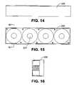
- FIG. 14is a front view of the outer loop fan module of the heat exchanger of FIG. 11 ;
- FIG. 15is a top view of the outer loop fan module of FIG. 14 ;
- FIG. 16is a section view of the outer loop fan module of FIG. 14 (along line A-A in FIG. 15 );
- FIG. 17is a front perspective view of the electronics equipment cabinet of FIG. 1 (doors and panels removed) illustrating the application of sound insulation and/or thermal insulation;
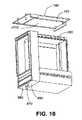
- FIG. 18a rear perspective view of the cabinet (doors and panels removed) illustrating the application of sound insulation and/or thermal insulation;
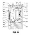
- FIG. 19is a section view (along line A-A in FIG. 1 ) illustrating air flows through the electronics equipment cabinet.
- FIG. 1is a front view illustrating an electronics equipment cabinet 100 in accordance with an embodiment of the invention.
- FIG. 2is a top view of the cabinet 100 .
- FIG. 3is a section view of the cabinet 100 (along line A-A in FIG. 1 ).
- FIG. 4is a front perspective view of the cabinet 100 .
- FIG. 5is a rear perspective view of the cabinet 100 .
- FIG. 6is a front perspective exploded view of the cabinet 100 .
- FIG. 7is a front view (doors and panels removed) of the cabinet 100 .
- FIG. 8is a left side view (doors and panels removed) of the cabinet 100 .
- the cabinet 100has a frame or housing 110 in which is formed an electronics equipment compartment 200 , a battery compartment 220 , a splice compartment 600 , and a cable entry compartment 660 .
- the electronics equipment compartment 200is positioned above the battery compartment 220 and the splice compartment 600 is positioned above the cable entry compartment 660 , the splice and cable entry compartments 600 , 660 being generally adjacent to the electronics equipment and battery compartments 200 , 220 , respectively.
- the electronics equipment compartment 200has a front door 120 for providing access to the compartment 200 and to an exhaust duct 300 , which will be described below.
- the electronics equipment compartment 200is for mounting electronics equipment 210 such as telecommunications equipment 211 , DC (Direct Current) power supplies 212 , and fiber termination panels 213 .
- the front door 120has ventilation openings 121 , the operation of which will be described in more detail below.
- the front door 120may be mounted to the housing 110 or compartment 200 with hinges, pins, etc.
- the battery compartment 220has a removable cover 130 for providing access to the compartment 220 .
- the battery compartment 220is for mounting batteries 221 to provide standby power to the electronics equipment 210 .
- the removable cover 130has ventilation openings 131 , the operation of which will be described in more detail below.
- the removable cover 130may be mounted to the housing 110 with tabs, pins, etc.
- the splice and cable entry compartments 600 , 660share a side door 140 for providing access to these compartments 600 , 660 .
- the side door 140has ventilation openings 141 opening into the cable entry compartment 660 , the operation of which will be described in more detail below.
- the splice compartment 600is for mounting cable termination blocks 610 , 620 for POTS (Plain Old Telephone Service) lines, DSL (Digital Subscriber Line) lines, etc.
- the splice compartment 600may also house an AC (Alternating Current) power panel 640 for providing AC power to the DC power supplies 212 to power the electronics equipment 210 and an AC convenience outlet 630 .
- the cable entry compartment 660facilitates the entry of cables (not shown) to the splice compartment 600 and cabinet 100 . These cables enter the cable entry compartment 660 though an opening 690 in the bottom of that compartment 660 .
- the side door 140may be mounted to the housing 110 with hinges, pins, etc.
- the housing 110has separate electronics equipment, battery, splice, and cable entry compartments 200 , 220 , 600 , 660 . Suitable openings (not shown) are provided between compartments for the passage of wiring (not shown).
- a fan 810is mounted in the cable entry compartment 660 through the inner panel or wall 650 separating the cable entry compartment 660 from the battery compartment 220 . Noting that the ventilation openings 141 in the side door 140 open into the cable entry compartment 660 , the fan 810 functions to draw air in through the ventilation openings 141 in the side door 140 , through the panel 650 , across the battery compartment 220 , and out through the ventilation openings 131 in the battery compartment cover 130 .
- the air flowis in the opposite direction with the fan 810 functioning to draw air in through the ventilation openings 131 in the battery compartment cover 130 , across the battery compartment 220 , through the panel 650 , and out through the ventilation openings 141 in the side door 140 .
- FIG. 9is a perspective view (exploded) of the inner side of the front door 120 of the electronics equipment cabinet 100 of FIG. 1 .
- FIG. 10is a front perspective view (top panel 150 removed) of the cabinet 100 .
- FIG. 11is a front view of the heat exchanger 320 mounted in the front door 120 of FIG. 9 .
- FIG. 12is a top view of the heat exchanger 320 .
- FIG. 13is a right side view of the heat exchanger 320 .
- FIG. 14is a front view of the outer loop fan module 330 of the heat exchanger 320 of FIG. 11 .
- FIG. 15is a top view of the outer loop fan module 330 .
- FIG. 16is a section view of the outer loop fan module 330 (along line A-A in FIG. 15 ).
- the enclosurehas a top casing or panel 150 spaced from a top surface 1020 of the electronics equipment compartment 200 to form an enclosed exhaust duct 300 therebetween.
- the exhaust duct 300extends across the top of the electronics equipment compartment 200 , from the front door 120 to the rear wall or panel 500 of the electronics equipment compartment 200 .
- the exhaust duct 300has a front inlet opening 390 at the front door 120 and a rear outlet opening 395 at the rear panel 500 .
- the rear panel 500extends upwards to cap the rear opening 395 of the exhaust duct 300 and ventilation openings 501 for the exhaust duct 300 are provided in the rear panel 500 .
- the ventilation openings 501may be integrated into the top panel 150 .
- the front inlet opening 390 of the exhaust duct 300engages an outer loop fan module 330 of a heat exchanger 320 mounted in the front door 120 , as will be described in more detail below.
- the top panel 150may be provided with one or more lifting eyes 160 mounted therethrough to facilitate lifting of the cabinet 100 .
- the front door 120has an outer casing or door 900 fitted over an inner panel or door 910 .
- the inner door 910isolates the electronics equipment compartment 200 from the exterior environment when the front door 120 is closed.
- the outer door 900is mounted over the outer surface 912 of the inner door 910 .
- the outer surface 902 of the outer door 900faces the environment while the inner surface 901 of the outer door 900 faces the outer surface 912 of the inner door 910 .
- the outer door 900is box-shaped such that when it is mounted over the outer surface 912 of the inner door 910 an enclosed door intake duct 360 is formed.
- the ventilation openings 121 in the outer door 120open into this door intake duct 360 .
- the outer door 900 and inner door 910are fastened together and function as one unit (i.e., a single door).
- the heat exchanger 320is mounted in the inner door 910 .
- the heat exchanger 320has a enclosed outer loop duct 340 mounted on the outer surface 912 of the inner door 910 .
- the heat exchanger 320has an enclosed inner loop duct 310 mounted on the inner surface 911 of the inner door 910 .
- the outer loop duct 340 and the inner loop duct 310are generally coextensive being separated by a heat exchanger core 1210 which may be, or form, a portion of the inner door 910 .
- the heat exchanger corehas an inner surface 1211 facing the inner loop duct 310 and an outer surface 1212 facing the outer loop duct 340 .
- the outer loop duct 340is located in the door compartment 360 and the inner loop duct 310 is located in the electronics equipment compartment 200 .
- the outer loop duct 340is spaced from the inner surface 901 of the outer door 900 . This spacing allows for the optional application of sound insulation 1710 and/or thermal insulation 1720 on the inner surface 901 of the outer door 900 and for the circulation of air within the door intake duct 360 .
- the outer loop duct 340 of the heat exchanger 320has vertical heat radiating fins 1220 disposed therein and forming part of the heat exchanger core 1210 to improve heat transfer efficiency.
- the fins 1220may be heat pipes, corrugated surfaces, or other heat exchanging elements known in the art.
- the outer loop duct 340has an outlet opening 341 at its top end and an inlet opening 342 at its bottom end allowing for the passage of air therethrough.
- the inner loop duct 310has an inlet opening 322 at its top end an outlet opening 323 at its bottom end allowing for the passage of air therethrough. Both the inlet and outlet openings 322 , 323 face into the electronics equipment compartment 200 .
- the inner loop duct 310has vertical heat radiating fins 1120 disposed therein and forming part of the heat exchanger core 1210 to improve heat transfer efficiency.
- the fins 1120may be heat pipes, corrugated surfaces, or other heat exchanging elements known in the art.
- the inner loop duct 310has one or more fans 321 mounted at the bottom outlet opening 323 for drawing air in the electronics equipment compartment 200 over the electronics equipment 210 , through the top inlet opening 322 in the inner loop duct 310 , over the fins 1120 of the heat exchanger core 1210 disposed in the inner loop duct 310 , and out through the bottom outlet opening 323 of the inner loop duct 310 .
- This air flowwill be referred to as the inner loop air flow 1910 below.
- the fans 321may be located at the top inlet opening 322 .
- the fins 1120 , 1220may represent opposite sides of a corrugated surface forming the heater exchanger core 1210 .
- An outer loop fan module 330is mounted above the top outlet opening 341 of the outer loop duct 340 on the outer surface 912 of the inner door 910 .
- the outer loop fan module 330is mounted over an opening 301 in the inner door 910 which, when the front door 120 is in a closed position, is aligned with the front inlet opening 390 of the exhaust duct 300 .
- the outer loop fan module 330is elbow-duct shaped having a bottom inlet opening 334 aligned with the top outlet opening 341 of the outer loop duct 340 and having a top outlet opening 335 aligned with the opening 301 in the inner door 910 .
- the outer loop fan module 330has one or more fans 331 mounted therein for drawing air from the external environment through the ventilation openings 121 in the front door 120 , through the door intake duct 360 , through the bottom inlet opening 342 of the outer loop duct 340 , over the fins 1220 of the heat exchanger core 1210 disposed in the outer loop duct 340 , through the top outlet opening 341 in the outer loop duct 310 , through the bottom inlet opening 334 of the outer loop fan module 330 , through the outer loop fan module 330 , through the top outlet opening 335 of the outer loop fan module 330 , through the opening 301 in the inner door 910 , through the front inlet opening 390 of the exhaust duct 300 , through the exhaust duct 300 , through the rear outlet opening 395 of the exhaust duct 300 , and out through the ventilation openings 501 in the rear panel 500 .
- This air flowwill be referred to as the outer loop air flow 1920 below.
- outer loop fan module 330may be a single unit.
- FIG. 17is a front perspective view of the electronics equipment cabinet 100 of FIG. 1 (doors 120 , 140 and panels 130 removed) illustrating the application of sound insulation 1710 and/or thermal insulation 1720 .
- FIG. 18a rear perspective view of the cabinet 100 (doors 120 , 140 and panels 130 removed) illustrating the application of sound insulation 1710 and/or thermal insulation 1720 .
- optional thermal insulation 1720 and/or sound insulation 1710may be applied to the inner surface 901 of the front door 900 , to the inner surface 151 of the top panel 150 , and to the inner surfaces of exterior facing walls of the electronics equipment and splice compartments 200 , 600 .
- the sound insulation 1710functions to reduce noise emissions generated by the fans 321 , 331 and/or electronic equipment 210 .
- the thermal insulation 1720functions to reduce solar/thermal loading from the sun and/or the external environment.
- FIG. 19is a section view (along line A-A in FIG. 1 ) illustrating air flows 1910 , 1920 through the electronics equipment cabinet 100 .
- inner loop air flow 1910circulates warm interior air from the top of the electronics equipment compartment 200 through the inner loop duct 310 of the heat exchanger 320 where heat is transferred to cool exterior air being circulated through the outer loop duct 340 of the heat exchanger 320 .
- the two air flows 1910 and 1920are isolated and do not mix (i.e., exterior air does not enter the electronics equipment compartment 200 ).
- the interior airflows in a direction from top to bottom of the inner loop duct 310 while the exterior air flows in a direction from bottom to top of the outer loop duct 340 .
- the heat exchanger 320may be referred to as a “counterflow” heat exchanger. These opposite air flow directions improve the heat transfer efficiency of the heat exchanger 320 .
- the cooled interior airexits the inner loop duct 310 into the bottom of the electronics equipment compartment 200 where it absorbs heat from the electronics equipment 210 and is warmed as it rises to the top of the compartment 200 .
- One or more vertical baffles 380may be provided at the bottom of the electronics equipment compartment 200 , extending from the front to the back of the compartment 200 , to distribute and direct the cooled air over the electronics equipment 210 .
- the cool exterior air in the outer loop duct 340absorbs heat from the interior air, is warmed, and is expelled through the exhaust duct 300 .
- the top panel 150being located on the top of the cabinet 100 , absorbs heat from the sun (i.e., solar thermal loading) when the cabinet 100 is located outdoors. This heat is transferred from the inner surface 151 of the top panel 150 to the exterior air flowing through the exhaust duct 300 further warming this air before it is expelled through the ventilation openings 501 at the rear of the cabinet 100 .
- the air flows 1910 , 1920are facilitated by natural convection rather than by one or more of the inner loop and outer loop fans 321 , 331 .
- the cabinet 100is primarily constructed from sheet metal.
- the cabinet 100 and its front door 120allows for the ducting 300 , 360 of the outer loop air flow 1920 both before and after the fans 331 and heat exchanger 230 .
- This ducting 300 , 360may have sound absorbing/attenuating material 1710 added to the walls thereof to create sound deadening spaces.
- This ducting 300 , 360also serves to insulate the electronics compartment 200 from solar loading on the corresponding external surfaces.
- the placement of the outer loop fan module 330 between the outer loop duct 340 and the exhaust duct 300 , well away from the ventilation openings 121 , 501 in the front door 120 and rear panel 500reduces fan 331 noise emitted by the cabinet 100 .
- this placementimproves fan 331 life as the fans 331 , being remote from the ventilation openings 121 , 501 , are protected from the elements (i.e., rain, snow, dust, etc.). Furthermore, the reduction in solar loading on the top panel 150 by the exhaust duct 300 allows for a smaller capacity heat exchanger 320 and fans 321 , 331 further enhancing the efficiency of the cabinet 100 .
- the baffling 380 provided in the electronics equipment compartment 200improves circulation of cooled interior air over the heat producing electronics equipment 210 hence increasing heat transfer from this equipment.
- the location of the ventilation openings 121 , 501 on opposite sides (i.e., front and back) of the cabinet 100helps to prevent re-circulation of exterior air hence improving the thermal efficiency of the cabinet.
Landscapes
- Engineering & Computer Science (AREA)
- Aviation & Aerospace Engineering (AREA)
- Physics & Mathematics (AREA)
- Thermal Sciences (AREA)
- Microelectronics & Electronic Packaging (AREA)
- Cooling Or The Like Of Electrical Apparatus (AREA)
Abstract
Description
Claims (52)
Priority Applications (1)
| Application Number | Priority Date | Filing Date | Title |
|---|---|---|---|
| US11/313,748US7312993B2 (en) | 2005-12-22 | 2005-12-22 | Electronics equipment cabinet |
Applications Claiming Priority (1)
| Application Number | Priority Date | Filing Date | Title |
|---|---|---|---|
| US11/313,748US7312993B2 (en) | 2005-12-22 | 2005-12-22 | Electronics equipment cabinet |
Publications (2)
| Publication Number | Publication Date |
|---|---|
| US20070144704A1 US20070144704A1 (en) | 2007-06-28 |
| US7312993B2true US7312993B2 (en) | 2007-12-25 |
Family
ID=38192249
Family Applications (1)
| Application Number | Title | Priority Date | Filing Date |
|---|---|---|---|
| US11/313,748Expired - Fee RelatedUS7312993B2 (en) | 2005-12-22 | 2005-12-22 | Electronics equipment cabinet |
Country Status (1)
| Country | Link |
|---|---|
| US (1) | US7312993B2 (en) |
Cited By (33)
| Publication number | Priority date | Publication date | Assignee | Title |
|---|---|---|---|---|
| US20080068798A1 (en)* | 2006-09-20 | 2008-03-20 | Mark Hendrix | Outside plant cabinet thermal system |
| US20080137296A1 (en)* | 2006-12-11 | 2008-06-12 | Westell Technologies, Inc. | Active Cooling of Outdoor Enclosure Under Solar Loading |
| US20080213653A1 (en)* | 2006-10-06 | 2008-09-04 | Panasonic Ev Energy Co., Ltd. | Battery pack |
| US20080233858A1 (en)* | 2007-02-22 | 2008-09-25 | Tellabs Operations, Inc. | Apparatus, system, and method for venting a chassis |
| US20080257639A1 (en)* | 2007-04-17 | 2008-10-23 | Fujitsu Limited | Storage box for electronic apparatus |
| US20090260384A1 (en)* | 2008-04-21 | 2009-10-22 | International Business Machines Corporation | Coolant Distribution System For A Rack Having A Rear-Door Heat Exchanger |
| US20090262501A1 (en)* | 2008-04-21 | 2009-10-22 | International Business Machines Corporation | Rack With Integrated Rear-Door Heat Exchanger |
| US20090310300A1 (en)* | 2008-06-11 | 2009-12-17 | Minebea Co., Ltd. | Flow-Through Air Conditioning for Electronics Racks |
| US20100059270A1 (en)* | 2008-09-11 | 2010-03-11 | Joseph Yeh | Hybrid cooling system for outdoor electronics enclosure |
| US20100118492A1 (en)* | 2007-02-14 | 2010-05-13 | Vestas Wind Systems A/S | System for Recirculation of Air in a Component of a Wind Turbine |
| US20110163545A1 (en)* | 2009-08-28 | 2011-07-07 | Mitsubishi Heavy Industries, Ltd. | Wind turbine for wind power generation |
| US20110232860A1 (en)* | 2010-03-26 | 2011-09-29 | Trane International Inc. | Air Handling Unit With Inner Wall Space |
| US20110279967A1 (en)* | 2007-05-17 | 2011-11-17 | International Business Machines Corporation | Techniques for Data Center Cooling |
| CN103458662A (en)* | 2013-08-30 | 2013-12-18 | 华为技术有限公司 | Heat radiator and outdoor communication equipment cabinet with same |
| US8760863B2 (en) | 2011-10-31 | 2014-06-24 | International Business Machines Corporation | Multi-rack assembly with shared cooling apparatus |
| US8797740B2 (en) | 2011-10-31 | 2014-08-05 | International Business Machines Corporation | Multi-rack assembly method with shared cooling unit |
| US8804334B2 (en) | 2011-05-25 | 2014-08-12 | International Business Machines Corporation | Multi-rack, door-mounted heat exchanger |
| US8919143B2 (en) | 2011-05-25 | 2014-12-30 | Lenovo Enterprise Solutions (Singapore) Pte. Ltd. | Air-cooling wall with slidable heat exchangers |
| US20170207607A1 (en)* | 2016-01-20 | 2017-07-20 | Lsis Co., Ltd. | Distributing panel |
| US20170332521A1 (en)* | 2016-05-13 | 2017-11-16 | Toshiba International Corporation | Outdoor ups unit system and method |
| US9839163B2 (en) | 2011-03-02 | 2017-12-05 | Inertech Ip Llc | Modular IT rack cooling assemblies and methods for assembling same |
| US10197310B2 (en) | 2014-06-20 | 2019-02-05 | Nortek Air Solutions Canada, Inc. | Systems and methods for managing conditions in enclosed space |
| US10401054B2 (en) | 2010-03-26 | 2019-09-03 | Trane International Inc. | Air handling unit with integral inner wall features |
| US10451295B2 (en) | 2014-12-22 | 2019-10-22 | Diversified Control, Inc. | Equipment enclosure with multi-mode temperature control system |
| US10488061B2 (en) | 2016-03-16 | 2019-11-26 | Inertech Ip Llc | System and methods utilizing fluid coolers and chillers to perform in-series heat rejection and trim cooling |
| US10772226B2 (en) | 2018-03-27 | 2020-09-08 | Otis Elevator Company | Waterproof cover |
| US10782045B2 (en) | 2015-05-15 | 2020-09-22 | Nortek Air Solutions Canada, Inc. | Systems and methods for managing conditions in enclosed space |
| US10834855B2 (en) | 2016-01-08 | 2020-11-10 | Nortek Air Solutions Canada, Inc. | Integrated make-up air system in 100% air recirculation system |
| US10893632B2 (en) | 2017-05-12 | 2021-01-12 | Diversified Control, Inc. | Equipment enclosure free-air cooling assembly with indexing pre-screen |
| US20220225534A1 (en)* | 2021-01-14 | 2022-07-14 | Super Micro Computer, Inc. | Telecommunication cabinet with hidden anti-theft heat dissipation module |
| US11602073B2 (en)* | 2020-05-27 | 2023-03-07 | Sungrow Power Supply Co., Ltd. | Heat dissipating system and power cabinet |
| US12038198B2 (en) | 2015-05-15 | 2024-07-16 | Nortek Air Solutions Canada, Inc. | Systems and methods for providing cooling to a heat load |
| US12442558B2 (en) | 2023-09-29 | 2025-10-14 | Nortek Air Solutions Canada, Inc. | Using liquid to air membrane energy exchanger for liquid cooling |
Families Citing this family (34)
| Publication number | Priority date | Publication date | Assignee | Title |
|---|---|---|---|---|
| DE112007003457A5 (en)* | 2007-02-13 | 2010-01-21 | Siemens Aktiengesellschaft | Electrical system with a container |
| US20080288193A1 (en)* | 2007-05-17 | 2008-11-20 | International Business Machines Corporation | Techniques for Analyzing Data Center Energy Utilization Practices |
| US12185512B2 (en) | 2007-11-16 | 2024-12-31 | Manufacturing Resources International, Inc. | Electronic display assembly with thermal management |
| USD587042S1 (en) | 2008-02-21 | 2009-02-24 | Milestone Av Technologies Llc | Equipment cabinet |
| US8654302B2 (en) | 2008-03-03 | 2014-02-18 | Manufacturing Resources International, Inc. | Heat exchanger for an electronic display |
| US10827656B2 (en) | 2008-12-18 | 2020-11-03 | Manufacturing Resources International, Inc. | System for cooling an electronic image assembly with circulating gas and ambient gas |
| US20110183599A1 (en)* | 2010-01-26 | 2011-07-28 | Channell Commercial Corporation | Uninteruptable power supply enclosure and battery locker |
| US20120139256A1 (en)* | 2011-10-06 | 2012-06-07 | General Electric Company | Wind turbine installation with a self-contained power production component enclosure |
| DE102012011203B4 (en)* | 2012-06-06 | 2014-03-20 | Rittal Gmbh & Co. Kg | Arrangement for controlling the temperature of arranged in a cabinet electrical components |
| US20140036442A1 (en)* | 2012-07-31 | 2014-02-06 | Alcatel-Lucent Deutschland Ag | Outdoor stackable telecommunications equipment cabinet family with flexible thermal and interface management and method of deploying the same |
| CN105850231B (en)* | 2014-01-17 | 2019-03-26 | 瑞典爱立信有限公司 | Cabinet for electronic equipment |
| JP6305564B2 (en) | 2014-04-30 | 2018-04-04 | マニュファクチャリング・リソーシズ・インターナショナル・インコーポレーテッド | Back-to-back electronic display assembly |
| US20160234963A1 (en)* | 2015-02-10 | 2016-08-11 | Emerson Network Power, Energy Systems, North America, Inc. | Enclosures and methods for removing hydrogen gas from enclosures |
| US10820445B2 (en) | 2016-03-04 | 2020-10-27 | Manufacturing Resources International, Inc. | Cooling system for double sided display assembly |
| KR102262912B1 (en) | 2017-04-27 | 2021-06-10 | 매뉴팩처링 리소시스 인터내셔널 인코포레이티드 | A system and method for preventing warping of a display device |
| US10485113B2 (en) | 2017-04-27 | 2019-11-19 | Manufacturing Resources International, Inc. | Field serviceable and replaceable display |
| US10732688B2 (en)* | 2018-03-09 | 2020-08-04 | Cisco Technology, Inc. | Delivery of AC power with higher power PoE (power over ethernet) systems |
| US10602626B2 (en) | 2018-07-30 | 2020-03-24 | Manufacturing Resources International, Inc. | Housing assembly for an integrated display unit |
| US11096317B2 (en) | 2019-02-26 | 2021-08-17 | Manufacturing Resources International, Inc. | Display assembly with loopback cooling |
| US10795413B1 (en) | 2019-04-03 | 2020-10-06 | Manufacturing Resources International, Inc. | Electronic display assembly with a channel for ambient air in an access panel |
| US11665861B2 (en)* | 2020-01-15 | 2023-05-30 | Dell Products, L.P. | Edge datacenter nano enclosure with chimney and return air containment plenum |
| US11477923B2 (en) | 2020-10-02 | 2022-10-18 | Manufacturing Resources International, Inc. | Field customizable airflow system for a communications box |
| US11778757B2 (en) | 2020-10-23 | 2023-10-03 | Manufacturing Resources International, Inc. | Display assemblies incorporating electric vehicle charging equipment |
| US11470749B2 (en) | 2020-10-23 | 2022-10-11 | Manufacturing Resources International, Inc. | Forced air cooling for display assemblies using centrifugal fans |
| US11966263B2 (en) | 2021-07-28 | 2024-04-23 | Manufacturing Resources International, Inc. | Display assemblies for providing compressive forces at electronic display layers |
| US12408312B2 (en) | 2021-07-28 | 2025-09-02 | Manufacturing Resources International, Inc. | Display assemblies with vents |
| US11744054B2 (en) | 2021-08-23 | 2023-08-29 | Manufacturing Resources International, Inc. | Fan unit for providing improved airflow within display assemblies |
| US11919393B2 (en) | 2021-08-23 | 2024-03-05 | Manufacturing Resources International, Inc. | Display assemblies inducing relatively turbulent flow and integrating electric vehicle charging equipment |
| US11762231B2 (en) | 2021-08-23 | 2023-09-19 | Manufacturing Resources International, Inc. | Display assemblies inducing turbulent flow |
| US11968813B2 (en) | 2021-11-23 | 2024-04-23 | Manufacturing Resources International, Inc. | Display assembly with divided interior space |
| US12072561B2 (en) | 2022-07-22 | 2024-08-27 | Manufacturing Resources International, Inc. | Self-contained electronic display assembly, mounting structure and methods for the same |
| US12010813B2 (en) | 2022-07-22 | 2024-06-11 | Manufacturing Resources International, Inc. | Self-contained electronic display assembly, mounting structure and methods for the same |
| US12035486B1 (en) | 2022-07-25 | 2024-07-09 | Manufacturing Resources International, Inc. | Electronic display assembly with fabric panel communications box |
| US20240074088A1 (en)* | 2022-08-23 | 2024-02-29 | Hamilton Sundstrand Corporation | Debris-resistant cooling path |
Citations (10)
| Publication number | Priority date | Publication date | Assignee | Title |
|---|---|---|---|---|
| US5467250A (en)* | 1994-03-21 | 1995-11-14 | Hubbell Incorporated | Electrical cabinet with door-mounted heat exchanger |
| US6164369A (en) | 1999-07-13 | 2000-12-26 | Lucent Technologies Inc. | Door mounted heat exchanger for outdoor equipment enclosure |
| US6225554B1 (en) | 1997-12-11 | 2001-05-01 | Avaya Technology Corp. | EMI shielded enclosure |
| US6652373B2 (en)* | 2001-05-16 | 2003-11-25 | Sanmina-Sci Corporation | Cooling airflow distribution device |
| US6742583B2 (en)* | 1999-08-20 | 2004-06-01 | Nokia Corporation | Cooling system for a cabinet |
| US6775137B2 (en)* | 2002-11-25 | 2004-08-10 | International Business Machines Corporation | Method and apparatus for combined air and liquid cooling of stacked electronics components |
| US20050016195A1 (en)* | 2001-10-18 | 2005-01-27 | Rainer Bretschneider | Sealing assembly |
| US6877551B2 (en) | 2002-07-11 | 2005-04-12 | Avaya Technology Corp. | Systems and methods for weatherproof cabinets with variably cooled compartments |
| US6889752B2 (en) | 2002-07-11 | 2005-05-10 | Avaya Technology Corp. | Systems and methods for weatherproof cabinets with multiple compartment cooling |
| US7254022B2 (en)* | 2004-04-26 | 2007-08-07 | Knuerr Ag | Cooling system for equipment and network cabinets and method for cooling equipment and network cabinets |
- 2005
- 2005-12-22USUS11/313,748patent/US7312993B2/ennot_activeExpired - Fee Related
Patent Citations (10)
| Publication number | Priority date | Publication date | Assignee | Title |
|---|---|---|---|---|
| US5467250A (en)* | 1994-03-21 | 1995-11-14 | Hubbell Incorporated | Electrical cabinet with door-mounted heat exchanger |
| US6225554B1 (en) | 1997-12-11 | 2001-05-01 | Avaya Technology Corp. | EMI shielded enclosure |
| US6164369A (en) | 1999-07-13 | 2000-12-26 | Lucent Technologies Inc. | Door mounted heat exchanger for outdoor equipment enclosure |
| US6742583B2 (en)* | 1999-08-20 | 2004-06-01 | Nokia Corporation | Cooling system for a cabinet |
| US6652373B2 (en)* | 2001-05-16 | 2003-11-25 | Sanmina-Sci Corporation | Cooling airflow distribution device |
| US20050016195A1 (en)* | 2001-10-18 | 2005-01-27 | Rainer Bretschneider | Sealing assembly |
| US6877551B2 (en) | 2002-07-11 | 2005-04-12 | Avaya Technology Corp. | Systems and methods for weatherproof cabinets with variably cooled compartments |
| US6889752B2 (en) | 2002-07-11 | 2005-05-10 | Avaya Technology Corp. | Systems and methods for weatherproof cabinets with multiple compartment cooling |
| US6775137B2 (en)* | 2002-11-25 | 2004-08-10 | International Business Machines Corporation | Method and apparatus for combined air and liquid cooling of stacked electronics components |
| US7254022B2 (en)* | 2004-04-26 | 2007-08-07 | Knuerr Ag | Cooling system for equipment and network cabinets and method for cooling equipment and network cabinets |
Cited By (58)
| Publication number | Priority date | Publication date | Assignee | Title |
|---|---|---|---|---|
| US20080068798A1 (en)* | 2006-09-20 | 2008-03-20 | Mark Hendrix | Outside plant cabinet thermal system |
| US20080213653A1 (en)* | 2006-10-06 | 2008-09-04 | Panasonic Ev Energy Co., Ltd. | Battery pack |
| US8173286B2 (en)* | 2006-10-06 | 2012-05-08 | Panasonic Ev Energy Co., Ltd. | Battery pack |
| US20080137296A1 (en)* | 2006-12-11 | 2008-06-12 | Westell Technologies, Inc. | Active Cooling of Outdoor Enclosure Under Solar Loading |
| US20100118492A1 (en)* | 2007-02-14 | 2010-05-13 | Vestas Wind Systems A/S | System for Recirculation of Air in a Component of a Wind Turbine |
| US20080233858A1 (en)* | 2007-02-22 | 2008-09-25 | Tellabs Operations, Inc. | Apparatus, system, and method for venting a chassis |
| US8944896B2 (en)* | 2007-02-22 | 2015-02-03 | Tellabs Operations, Inc. | Apparatus, system, and method for venting a chassis |
| US20080257639A1 (en)* | 2007-04-17 | 2008-10-23 | Fujitsu Limited | Storage box for electronic apparatus |
| US8408356B2 (en)* | 2007-04-17 | 2013-04-02 | Fujitsu Limited | Storage box for electronic apparatus |
| US8964375B2 (en)* | 2007-05-17 | 2015-02-24 | International Business Machines Corporation | Techniques for data center cooling |
| US8593815B2 (en)* | 2007-05-17 | 2013-11-26 | International Business Machines Corporation | Techniques for data center cooling |
| US20140063729A1 (en)* | 2007-05-17 | 2014-03-06 | International Business Machines Corporation | Techniques for Data Center Cooling |
| US20110279967A1 (en)* | 2007-05-17 | 2011-11-17 | International Business Machines Corporation | Techniques for Data Center Cooling |
| US7660116B2 (en) | 2008-04-21 | 2010-02-09 | International Business Machines Corporation | Rack with integrated rear-door heat exchanger |
| US20090262501A1 (en)* | 2008-04-21 | 2009-10-22 | International Business Machines Corporation | Rack With Integrated Rear-Door Heat Exchanger |
| US20090260384A1 (en)* | 2008-04-21 | 2009-10-22 | International Business Machines Corporation | Coolant Distribution System For A Rack Having A Rear-Door Heat Exchanger |
| US20090310300A1 (en)* | 2008-06-11 | 2009-12-17 | Minebea Co., Ltd. | Flow-Through Air Conditioning for Electronics Racks |
| US20100059270A1 (en)* | 2008-09-11 | 2010-03-11 | Joseph Yeh | Hybrid cooling system for outdoor electronics enclosure |
| US7929294B2 (en)* | 2008-09-11 | 2011-04-19 | Commscope Inc. Of North Carolina | Hybrid cooling system for outdoor electronics enclosure |
| US20110163545A1 (en)* | 2009-08-28 | 2011-07-07 | Mitsubishi Heavy Industries, Ltd. | Wind turbine for wind power generation |
| US8502405B2 (en)* | 2009-08-28 | 2013-08-06 | Mitsubishi Heavy Industries, Ltd. | Wind turbine for wind power generation |
| US11920822B2 (en) | 2010-03-26 | 2024-03-05 | Trane International Inc. | Air handling unit with integral inner wall features |
| US10139115B2 (en)* | 2010-03-26 | 2018-11-27 | Trane International Inc. | Air handling unit with inner wall space |
| US10401054B2 (en) | 2010-03-26 | 2019-09-03 | Trane International Inc. | Air handling unit with integral inner wall features |
| US11585565B2 (en) | 2010-03-26 | 2023-02-21 | Trane International Inc. | Air handling unit with integral inner wall features |
| US20110232860A1 (en)* | 2010-03-26 | 2011-09-29 | Trane International Inc. | Air Handling Unit With Inner Wall Space |
| US9839163B2 (en) | 2011-03-02 | 2017-12-05 | Inertech Ip Llc | Modular IT rack cooling assemblies and methods for assembling same |
| US9314886B2 (en) | 2011-05-25 | 2016-04-19 | Lenovo Enterprise Solutions (Singapore) Pte. Ltd. | Multi-rack, door-mounted heat exchanger |
| US8919143B2 (en) | 2011-05-25 | 2014-12-30 | Lenovo Enterprise Solutions (Singapore) Pte. Ltd. | Air-cooling wall with slidable heat exchangers |
| US9321136B2 (en) | 2011-05-25 | 2016-04-26 | Lenovo Enterprise Solutions PTE. LTD. | Multi-rack, door-mounted heat exchanger |
| US9492899B2 (en) | 2011-05-25 | 2016-11-15 | Lenovo Enterprise Solutions (Singapore) Pte. Ltd. | Multi-rack, door-mounted heat exchanger |
| US8804334B2 (en) | 2011-05-25 | 2014-08-12 | International Business Machines Corporation | Multi-rack, door-mounted heat exchanger |
| US8817474B2 (en) | 2011-10-31 | 2014-08-26 | International Business Machines Corporation | Multi-rack assembly with shared cooling unit |
| US8817465B2 (en) | 2011-10-31 | 2014-08-26 | International Business Machines Corporation | Multi-rack assembly with shared cooling apparatus |
| US8760863B2 (en) | 2011-10-31 | 2014-06-24 | International Business Machines Corporation | Multi-rack assembly with shared cooling apparatus |
| US8797740B2 (en) | 2011-10-31 | 2014-08-05 | International Business Machines Corporation | Multi-rack assembly method with shared cooling unit |
| CN103458662B (en)* | 2013-08-30 | 2016-03-30 | 华为技术有限公司 | Radiator and there is the outdoor communication equipment cabinet of this radiator |
| CN103458662A (en)* | 2013-08-30 | 2013-12-18 | 华为技术有限公司 | Heat radiator and outdoor communication equipment cabinet with same |
| US10197310B2 (en) | 2014-06-20 | 2019-02-05 | Nortek Air Solutions Canada, Inc. | Systems and methods for managing conditions in enclosed space |
| US11015845B2 (en) | 2014-06-20 | 2021-05-25 | Nortek Air Solations Canada, Inc. | Systems and methods for managing conditions in enclosed space |
| US10451295B2 (en) | 2014-12-22 | 2019-10-22 | Diversified Control, Inc. | Equipment enclosure with multi-mode temperature control system |
| US12038198B2 (en) | 2015-05-15 | 2024-07-16 | Nortek Air Solutions Canada, Inc. | Systems and methods for providing cooling to a heat load |
| US10782045B2 (en) | 2015-05-15 | 2020-09-22 | Nortek Air Solutions Canada, Inc. | Systems and methods for managing conditions in enclosed space |
| US11815283B2 (en) | 2015-05-15 | 2023-11-14 | Nortek Air Solutions Canada, Inc. | Using liquid to air membrane energy exchanger for liquid cooling |
| US10834855B2 (en) | 2016-01-08 | 2020-11-10 | Nortek Air Solutions Canada, Inc. | Integrated make-up air system in 100% air recirculation system |
| US10461510B2 (en)* | 2016-01-20 | 2019-10-29 | Lsis Co., Ltd. | Modular distributing panel including a transformer |
| US20170207607A1 (en)* | 2016-01-20 | 2017-07-20 | Lsis Co., Ltd. | Distributing panel |
| US10488061B2 (en) | 2016-03-16 | 2019-11-26 | Inertech Ip Llc | System and methods utilizing fluid coolers and chillers to perform in-series heat rejection and trim cooling |
| US11867426B2 (en) | 2016-03-16 | 2024-01-09 | Inertech Ip Llc | System and methods utilizing fluid coolers and chillers to perform in-series heat rejection and trim cooling |
| US11415330B2 (en) | 2016-03-16 | 2022-08-16 | Inertech Ip Llc | System and methods utilizing fluid coolers and chillers to perform in-sertes heat rejection and trim cooling |
| US20170332521A1 (en)* | 2016-05-13 | 2017-11-16 | Toshiba International Corporation | Outdoor ups unit system and method |
| US10143116B2 (en)* | 2016-05-13 | 2018-11-27 | Toshiba International Corporation | Outdoor UPS unit system and method |
| US10893632B2 (en) | 2017-05-12 | 2021-01-12 | Diversified Control, Inc. | Equipment enclosure free-air cooling assembly with indexing pre-screen |
| US10772226B2 (en) | 2018-03-27 | 2020-09-08 | Otis Elevator Company | Waterproof cover |
| US11602073B2 (en)* | 2020-05-27 | 2023-03-07 | Sungrow Power Supply Co., Ltd. | Heat dissipating system and power cabinet |
| US11445633B2 (en)* | 2021-01-14 | 2022-09-13 | Super Micro Computer, Inc. | Telecommunication cabinet with hidden anti-theft heat dissipation module |
| US20220225534A1 (en)* | 2021-01-14 | 2022-07-14 | Super Micro Computer, Inc. | Telecommunication cabinet with hidden anti-theft heat dissipation module |
| US12442558B2 (en) | 2023-09-29 | 2025-10-14 | Nortek Air Solutions Canada, Inc. | Using liquid to air membrane energy exchanger for liquid cooling |
Also Published As
| Publication number | Publication date |
|---|---|
| US20070144704A1 (en) | 2007-06-28 |
Similar Documents
| Publication | Publication Date | Title |
|---|---|---|
| US7312993B2 (en) | Electronics equipment cabinet | |
| US6704198B2 (en) | Equipment enclosure with heat exchanger | |
| US7182208B2 (en) | Instrument rack with direct exhaustion | |
| CN100476690C (en) | Method and apparatus for reducing noise in a vented computer system | |
| US20040007347A1 (en) | Systems and methods for weatherproof cabinets with multiple compartment cooling | |
| WO2021223106A1 (en) | Heat dissipating cabinet and communication device | |
| JP2010041007A (en) | Cooling unit, electronic apparatus rack, cooling system, and construction method thereof | |
| CN114076027B (en) | Container type power station | |
| CN110461132A (en) | A control cabinet with good heat dissipation performance | |
| TW200417307A (en) | Environmental control kit for sealed cabinets | |
| CN213126970U (en) | Air-cooled heat dissipation system of VPX framework case | |
| JP2004044962A (en) | Cooling device | |
| WO2002037919A1 (en) | Climate control of an outdoor cabinet | |
| CN220061962U (en) | Electric control box assembly, outdoor unit and heating and ventilation equipment | |
| CN220545327U (en) | Machine room heat dissipation cabinet | |
| CN111878912A (en) | Outdoor unit radiating assembly, outdoor unit and air conditioner | |
| JP2010034446A (en) | Electronic apparatus storing rack | |
| WO2023246116A1 (en) | Heat dissipation structure of air conditioner box body and air conditioner | |
| CN213368433U (en) | Air circulation system of server cabinet | |
| CN210835855U (en) | Computer cabinet | |
| CN210608154U (en) | Small-size dampproofing heat dissipation protection against electric shock type electrical distribution box | |
| JP4276615B2 (en) | Electronic equipment storage box | |
| JP2004039692A (en) | Outdoor installation enclosure | |
| CN223266636U (en) | Ventilation and heat dissipation structure of charging device | |
| CN215819133U (en) | High-density BBU accommodating cabinet |
Legal Events
| Date | Code | Title | Description |
|---|---|---|---|
| AS | Assignment | Owner name:ALCATEL, FRANCE Free format text:ASSIGNMENT OF ASSIGNORS INTEREST;ASSIGNORS:BUNDZA, NICHOLAS ADAM;DE CECCO, STEFANO;ARLOTTA, ANGELO;REEL/FRAME:017403/0986;SIGNING DATES FROM 20051221 TO 20051222 | |
| STCF | Information on status: patent grant | Free format text:PATENTED CASE | |
| FEPP | Fee payment procedure | Free format text:PAYOR NUMBER ASSIGNED (ORIGINAL EVENT CODE: ASPN); ENTITY STATUS OF PATENT OWNER: LARGE ENTITY | |
| FPAY | Fee payment | Year of fee payment:4 | |
| AS | Assignment | Owner name:CREDIT SUISSE AG, NEW YORK Free format text:SECURITY AGREEMENT;ASSIGNOR:LUCENT, ALCATEL;REEL/FRAME:029821/0001 Effective date:20130130 Owner name:CREDIT SUISSE AG, NEW YORK Free format text:SECURITY AGREEMENT;ASSIGNOR:ALCATEL LUCENT;REEL/FRAME:029821/0001 Effective date:20130130 | |
| AS | Assignment | Owner name:ALCATEL LUCENT, FRANCE Free format text:RELEASE BY SECURED PARTY;ASSIGNOR:CREDIT SUISSE AG;REEL/FRAME:033868/0001 Effective date:20140819 | |
| FPAY | Fee payment | Year of fee payment:8 | |
| AS | Assignment | Owner name:OMEGA CREDIT OPPORTUNITIES MASTER FUND, LP, NEW YORK Free format text:SECURITY INTEREST;ASSIGNOR:WSOU INVESTMENTS, LLC;REEL/FRAME:043966/0574 Effective date:20170822 Owner name:OMEGA CREDIT OPPORTUNITIES MASTER FUND, LP, NEW YO Free format text:SECURITY INTEREST;ASSIGNOR:WSOU INVESTMENTS, LLC;REEL/FRAME:043966/0574 Effective date:20170822 | |
| AS | Assignment | Owner name:WSOU INVESTMENTS, LLC, CALIFORNIA Free format text:ASSIGNMENT OF ASSIGNORS INTEREST;ASSIGNOR:ALCATEL LUCENT;REEL/FRAME:044000/0053 Effective date:20170722 | |
| AS | Assignment | Owner name:BP FUNDING TRUST, SERIES SPL-VI, NEW YORK Free format text:SECURITY INTEREST;ASSIGNOR:WSOU INVESTMENTS, LLC;REEL/FRAME:049235/0068 Effective date:20190516 | |
| AS | Assignment | Owner name:WSOU INVESTMENTS, LLC, CALIFORNIA Free format text:RELEASE BY SECURED PARTY;ASSIGNOR:OCO OPPORTUNITIES MASTER FUND, L.P. (F/K/A OMEGA CREDIT OPPORTUNITIES MASTER FUND LP;REEL/FRAME:049246/0405 Effective date:20190516 | |
| FEPP | Fee payment procedure | Free format text:MAINTENANCE FEE REMINDER MAILED (ORIGINAL EVENT CODE: REM.); ENTITY STATUS OF PATENT OWNER: LARGE ENTITY | |
| LAPS | Lapse for failure to pay maintenance fees | Free format text:PATENT EXPIRED FOR FAILURE TO PAY MAINTENANCE FEES (ORIGINAL EVENT CODE: EXP.); ENTITY STATUS OF PATENT OWNER: LARGE ENTITY | |
| STCH | Information on status: patent discontinuation | Free format text:PATENT EXPIRED DUE TO NONPAYMENT OF MAINTENANCE FEES UNDER 37 CFR 1.362 | |
| FP | Lapsed due to failure to pay maintenance fee | Effective date:20191225 | |
| AS | Assignment | Owner name:OT WSOU TERRIER HOLDINGS, LLC, CALIFORNIA Free format text:SECURITY INTEREST;ASSIGNOR:WSOU INVESTMENTS, LLC;REEL/FRAME:056990/0081 Effective date:20210528 | |
| AS | Assignment | Owner name:WSOU INVESTMENTS, LLC, CALIFORNIA Free format text:RELEASE BY SECURED PARTY;ASSIGNOR:TERRIER SSC, LLC;REEL/FRAME:056526/0093 Effective date:20210528 |