US7311711B2 - Surgical distractor frame - Google Patents
Surgical distractor frameDownload PDFInfo
- Publication number
- US7311711B2 US7311711B2US10/326,655US32665502AUS7311711B2US 7311711 B2US7311711 B2US 7311711B2US 32665502 AUS32665502 AUS 32665502AUS 7311711 B2US7311711 B2US 7311711B2
- Authority
- US
- United States
- Prior art keywords
- shaft
- sleeve
- distractor
- bone
- elongate
- Prior art date
- Legal status (The legal status is an assumption and is not a legal conclusion. Google has not performed a legal analysis and makes no representation as to the accuracy of the status listed.)
- Expired - Lifetime
Links
- 230000007246mechanismEffects0.000claimsabstractdescription36
- 230000008878couplingEffects0.000claimsabstractdescription11
- 238000010168coupling processMethods0.000claimsabstractdescription11
- 238000005859coupling reactionMethods0.000claimsabstractdescription11
- 210000000988bone and boneAnatomy0.000claimsdescription33
- 239000000463materialSubstances0.000claimsdescription10
- 238000003384imaging methodMethods0.000claimsdescription6
- 239000002184metalSubstances0.000claimsdescription4
- 229910052751metalInorganic materials0.000claimsdescription4
- 229920003023plasticPolymers0.000claimsdescription4
- 239000004033plasticSubstances0.000claimsdescription4
- 239000002131composite materialSubstances0.000claimsdescription2
- 230000002452interceptive effectEffects0.000claimsdescription2
- 239000007769metal materialSubstances0.000claims1
- 208000010392Bone FracturesDiseases0.000description13
- 206010017076FractureDiseases0.000description13
- 210000002303tibiaAnatomy0.000description7
- 230000008901benefitEffects0.000description6
- 239000012634fragmentSubstances0.000description5
- 210000004872soft tissueAnatomy0.000description5
- 210000001519tissueAnatomy0.000description5
- 210000002414legAnatomy0.000description4
- 238000000034methodMethods0.000description4
- 210000003041ligamentAnatomy0.000description3
- 238000001356surgical procedureMethods0.000description3
- 238000002595magnetic resonance imagingMethods0.000description2
- 150000002739metalsChemical class0.000description2
- 238000012986modificationMethods0.000description2
- 230000004048modificationEffects0.000description2
- 230000008569processEffects0.000description2
- 230000008439repair processEffects0.000description2
- 210000000689upper legAnatomy0.000description2
- 230000000007visual effectEffects0.000description2
- 238000012800visualizationMethods0.000description2
- 208000027502Ankle fractureDiseases0.000description1
- 208000027418Wounds and injuryDiseases0.000description1
- 206010048049Wrist fractureDiseases0.000description1
- 210000003423ankleAnatomy0.000description1
- 230000003466anti-cipated effectEffects0.000description1
- 230000004323axial lengthEffects0.000description1
- 238000005452bendingMethods0.000description1
- 230000000903blocking effectEffects0.000description1
- 230000006835compressionEffects0.000description1
- 238000007906compressionMethods0.000description1
- 238000007796conventional methodMethods0.000description1
- 230000000694effectsEffects0.000description1
- 125000001475halogen functional groupChemical group0.000description1
- 210000000474heelAnatomy0.000description1
- 210000003127kneeAnatomy0.000description1
- 238000013421nuclear magnetic resonance imagingMethods0.000description1
- 238000002559palpationMethods0.000description1
- 229920000642polymerPolymers0.000description1
- 238000001454recorded imageMethods0.000description1
- 229910001220stainless steelInorganic materials0.000description1
- 239000010935stainless steelSubstances0.000description1
- 206010043827tibia fractureDiseases0.000description1
Images


Classifications
- A—HUMAN NECESSITIES
- A61—MEDICAL OR VETERINARY SCIENCE; HYGIENE
- A61B—DIAGNOSIS; SURGERY; IDENTIFICATION
- A61B17/00—Surgical instruments, devices or methods
- A61B17/56—Surgical instruments or methods for treatment of bones or joints; Devices specially adapted therefor
- A61B17/58—Surgical instruments or methods for treatment of bones or joints; Devices specially adapted therefor for osteosynthesis, e.g. bone plates, screws or setting implements
- A61B17/60—Surgical instruments or methods for treatment of bones or joints; Devices specially adapted therefor for osteosynthesis, e.g. bone plates, screws or setting implements for external osteosynthesis, e.g. distractors, contractors
- A61B17/66—Alignment, compression or distraction mechanisms
- A—HUMAN NECESSITIES
- A61—MEDICAL OR VETERINARY SCIENCE; HYGIENE
- A61B—DIAGNOSIS; SURGERY; IDENTIFICATION
- A61B17/00—Surgical instruments, devices or methods
- A61B17/56—Surgical instruments or methods for treatment of bones or joints; Devices specially adapted therefor
- A61B17/58—Surgical instruments or methods for treatment of bones or joints; Devices specially adapted therefor for osteosynthesis, e.g. bone plates, screws or setting implements
- A61B17/60—Surgical instruments or methods for treatment of bones or joints; Devices specially adapted therefor for osteosynthesis, e.g. bone plates, screws or setting implements for external osteosynthesis, e.g. distractors, contractors
- A61B17/64—Devices extending alongside the bones to be positioned
- A61B17/6408—Devices not permitting mobility, e.g. fixed to bed, with or without means for traction or reduction
- A—HUMAN NECESSITIES
- A61—MEDICAL OR VETERINARY SCIENCE; HYGIENE
- A61B—DIAGNOSIS; SURGERY; IDENTIFICATION
- A61B17/00—Surgical instruments, devices or methods
- A61B17/56—Surgical instruments or methods for treatment of bones or joints; Devices specially adapted therefor
- A61B17/58—Surgical instruments or methods for treatment of bones or joints; Devices specially adapted therefor for osteosynthesis, e.g. bone plates, screws or setting implements
- A61B17/60—Surgical instruments or methods for treatment of bones or joints; Devices specially adapted therefor for osteosynthesis, e.g. bone plates, screws or setting implements for external osteosynthesis, e.g. distractors, contractors
- A61B17/64—Devices extending alongside the bones to be positioned
- A61B17/6425—Devices extending alongside the bones to be positioned specially adapted to be fitted across a bone joint
- A—HUMAN NECESSITIES
- A61—MEDICAL OR VETERINARY SCIENCE; HYGIENE
- A61B—DIAGNOSIS; SURGERY; IDENTIFICATION
- A61B17/00—Surgical instruments, devices or methods
- A61B17/56—Surgical instruments or methods for treatment of bones or joints; Devices specially adapted therefor
- A61B17/58—Surgical instruments or methods for treatment of bones or joints; Devices specially adapted therefor for osteosynthesis, e.g. bone plates, screws or setting implements
- A61B17/60—Surgical instruments or methods for treatment of bones or joints; Devices specially adapted therefor for osteosynthesis, e.g. bone plates, screws or setting implements for external osteosynthesis, e.g. distractors, contractors
- A61B17/64—Devices extending alongside the bones to be positioned
- A61B17/6441—Bilateral fixators, i.e. with both ends of pins or wires clamped
Definitions
- This inventionrelates to distractors for use in surgery to repair broken, deformed or damaged bones and joints.
- the distraction framemay obstruct physical access to the patient's wound. Furthermore, from a visualization standpoint, the distraction frame may obstruct the surgeon's ability to see the surgical site and the ability to visualize the underlying tissue using X-ray imaging or other devices.
- FIG. 1Such a prior art distractor is illustrated in FIG. 1 .
- the prior art distractorcomprises an upper pin 102 which is introduced laterally through a patient's bone above a joint, for instance, into the femoral condyles 104 a and 104 b in a direction perpendicular to the long axis of the femur according to well known surgical procedures.
- a lower pin 106is introduced laterally below the joint into the patient's tibia 108 through the soft tissue of the bone in a direction substantially parallel to that of the upper pin 102 .
- the upper and lower pins 102 and 106are connected to each other on both sides of the femur 107 and tibia 108 by a pair of threaded rods 110 a and 110 b .
- Mounted to the threaded rod 110 ais a serrated wheel 112 a .
- One leg 116 a of an L-shaped member 114 ais rotatedly coupled to the wheel 112 a .
- the other leg 118 a of the L-shaped membercouples to the pin 106 .
- the leg 118 ais pierced by a cylindrical hole extending along its longitudinal axis. The cylindrical hole is of such a diameter as to receive a portion of the rod 110 a in a slidable manner and to guide the same.
- an L-shaped member 114 b and wheel 112 bcouple the pin 106 to threaded rod 110 b.
- Adjustments in the vertical distance between the pins 102 and 106can be made by turning the wheels 112 a - 112 b along the threaded rods 110 a and 110 b . After the pins 102 and 106 are in place, turning the wheels 112 a and 112 b in a downward manner will induce compression stresses within the threaded rods 110 a and 110 b.
- the rods 110 a and 110 bare relatively slender, the rods flex or buckle under compressive stresses. The buckling causes additional flexural stressed to develop within the rods. Furthermore, threads surrounding the exterior of the threaded rods 110 a and 110 b reduce the effective cross-sectional area of the rods and introduces residual stresses from threading process which further reduces the rod's structure strength.
- the present inventionprovides a distraction device that minimizes the obstruction of the surgical site while still providing the necessary distraction features to provide bone fragment alignment and overcome compressive forces of contracted soft tissue.
- the support member disposed over the surgical siteis formed of a material that is substantially radiolucent such that underlying tissue may be readily imaged.
- the present inventionprovides a distractor frame that has an expansion mechanism axially displaced from the surgical site being distracted.
- a distractor framecomprising an upper pin, a lower pin positioned substantially parallel to the upper pin, a pair of adjustment mechanisms, wherein each adjustment mechanism couples to the upper pin and the lower pin such that each adjustment mechanism is positioned generally perpendicular to upper and lower pins, wherein each adjustment mechanism comprises a shaft, a first means coupling the shaft for coupling the upper pin to the shaft, a threaded rod coupled to an end of the shaft, a cylindrical sleeve adapted for threadedly engaging the threaded rod, such that a portion of the shaft and a portion of the threaded rod may be positioned within the cylindrical sleeve, and a second means coupled to the cylindrical sleeve for coupling the lower pin.
- at least the shaftis formed of radiolucent material.
- FIG. 1is an isometric view illustrating a prior art device.
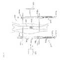
- FIG. 2is a partial cross-sectional top view of one embodiment of the present invention.
- FIG. 3is a partial cross-sectional side view of an embodiment of an adjustment mechanism used in the present invention.
- FIG. 4is a partial cross-sectional top view of one embodiment of the present invention shown applied to a patient's leg.
- FIGS. 2-4 of the drawingsin which like numbers designate like parts.
- well-known elementsare presented without detailed description in order not to obscure the present invention in unnecessary detail.
- details unnecessary to obtain a complete understanding of the present inventionhave been omitted inasmuch as such details are within the skills of persons of ordinary skill in the relevant art.
- Details regarding mechanisms used to connect and control the rotation of the various elements described hereinare omitted, as such mechanisms are within the skills of persons of ordinary skill in the relevant art.
- the distractor frame 200comprises a pair of upper and lower pins 202 and 204 , and a pair of adjustment mechanisms 206 a and 206 b .
- the upper and lower pins 202 and 204may be conventional 3/16 inch Steinmann pins.
- the upper and lower pins 202 and 204are connected to each other by the adjustment mechanisms 206 a and 206 b , which are virtually identical to each other.
- the adjustment mechanisms 206 a and 206 bextend from the left and right ends 212 a and 212 b of the upper pin 202 to the left and right ends 214 a and 214 b of the lower pin 204 , respectively.
- FIG. 3there is shown a side view of the adjustment mechanism 206 a .
- the adjustment mechanism 206 acomprises a main shaft 302 a .
- a pin connector 304 afor coupling the main shaft 302 a to the pin 202 .
- a first end 314 a of a cylindrical sleeve 316 ais coupled to a second pin connector 318 a .
- the cylindrical sleeve 316 ahas an interior bore running through its longitudinal axis adapted to receive a portion of main shaft 302 a .
- Pin connector 304includes a rod clamp 320 having a passage to receive pin 202 .
- Pin connectorfurther includes a base assembly 322 coupled to main shaft 302 a . It will be understood that nut 324 may be tightened to cause rod clamp 320 to tighten against pin 202 to thereby hold the relative positions. While a perpendicular relationship between pin 202 and shaft 302 a is illustrated in FIG. 2 , base assembly 322 and rod clamp 320 may be configured to permit angulations there between prior to tightening of nut 324 to accommodate a plurality of angular relationships during the distraction operation.
- a drive pattern 312 amaybe fixedly coupled to a second end 315 a of the threaded rod 310 a .
- the drive pattern 312 amay be a hexagon head adapted to be rotated by a hand tool.
- the turning mechanismcould be a wheel or handle adapted to be directly rotated by a human hand.
- the interior bore of sleeve 316 ais threaded to mate with an exterior threaded surface of the threaded rod 310 a .
- the interior borehas a diameter which is slightly larger than the exterior diameter of the main shaft 302 a such that cylindrical sleeve 316 a can slidably move in a longitudinal direction with respect to the main shaft 302 a .
- the second pin connector 318 aalso has an interior bore which is slightly larger than the exterior diameter of the main shaft 302 a such the second pin connector 318 a may slidably move with respect to rod 302 a .
- the cylindrical sleeve 316 a and second pin connector 318 amay be restrained from free movement by threaded rod 310 a which may be threadedly engaged the cylindrical sleeve 316 a.
- the adjustment mechanism 206 bmay have identical components to that of adjustment mechanism 206 a , and as such will not be separately described.
- all of the componentsmay be formed of medical grade stainless steel.
- the componentsmay be formed of alternative metals suited for medical applications.
- one or more of the componentsis formed a material that is substantially passive in the presence of X-rays or energy emitted for nuclear magnetic resonance imaging (MRI). It is contemplated that the components of the device would have limited halo or occlusive effect in generating a visual image with imaging devices. Such materials may include medical grade plastics, composites, polymers, and metals not interfering with imaging devices. It is further contemplated that at least the components adjacent the surgical site be substantially radiolucent.
- the embodimentwill be used to treat a fracture or osteotomy fragments of the tibia as illustrated in FIG. 4 .
- the lower pin 204may be introduced laterally into the patient's tibia 404 below the fracture 402 through the soft tissue of the tibia in a direction substantially parallel to that of the upper pin 202 .
- An optional appliance of a preliminary manual traction onto the pins to stretch the ligamentsmay be applied.
- the pin connectors 304 a , 304 b , 318 a , and 318 bare screwed respectively to secure the pins 202 and 204 to the adjustment mechanisms 206 a and 206 b.
- fracture 402is disposed between pins 202 and 204 , and the respective pin connectors.
- adjustment mechanisms 305 a and 305 bare axially displaced along the longitudinal axis of main shaft 206 a and 206 b , respectively, from the fracture 402 .
- the adjustment mechanismis disposed away from the surgical site.
- drive patterns 312 a and 312 bare disposed on the distal ends of the adjustment mechanisms such that they are axially displaced from the fracture as far as possible. It will be understood that instruments necessary to engage the drive patterns 312 a and 312 b will similarly be located away from the surgical site.
- surgeonmay have an unobstructed view of and access to the patient's surgical site while the present invention is operated to distract the tissue of interest. Still further, in the preferred embodiment illustrated, only the main shaft 206 a and 206 b are disposed adjacent the fracture 402 . This configuration minimizes the amount of components blocking physical and visual access to the surgical site.
- main shafts 302 a and 302 bare formed of substantially radiolucent material to permit visualization of fracture 402 with imaging equipment. While it is contemplated that the entire distractor may be constructed of radiolucent materials, in one preferred embodiment main shafts 302 a and 302 b are formed of medical grade plastic and the remaining components, including adjustment mechanisms 305 a and 305 b , are formed of medical grade metal. As illustrated in FIG. 4 , an energy source 500 , such as for example an X-ray source or MRI source, emits energy in the direction of arrow A.
- an energy source 500such as for example an X-ray source or MRI source, emits energy in the direction of arrow A.
- the energypasses substantially through main shaft 206 a , is at least partially blocked by tissue adjacent fracture 402 , passes substantially through main shaft 206 b and is recorded at device 502 .
- the recorded imagemay provide a substantially clear image of fracture 402 without undue interference from the distractor frame as the adjustment components are not in axial alignment with the energy path A of imaging equipment 500 and 502 .
- the turning mechanisms 312 a and 312 bmay now be used to precisely adjust the distance between the upper pin 202 and the lower pin 204 .
- rotating turning mechanism 312 awill also cause the threaded rod 310 a to rotate.
- the cylindrical sleeve 316 ais threadedly engaged with the threaded rod 310 a
- the rotation of the threaded rodwill cause the cylindrical sleeve 316 a to move longitudinally with respect to the main shaft 302 a .
- the lower pin 204is coupled to the cylindrical sleeve 316 a through the pin connector 318 a .
- the lower pin 204will also attempt to move. Consequently, the rotation of the turning mechanisms 312 a and 312 b may apply traction onto the pins 202 and 204 until they are sufficiently separated to bring the bone fragments to the desired location and/or the ligaments are adequately taut. During this operation, the tension in the patient's ligaments may be checked by conventional methods, such as palpation. Radiographic images may be taken during the distraction process through the main shafts of the distractor frame to monitor the bone fragment distraction and alignment.
- the pin 202may be replaced by a wire or cable that extends through a bone portion and is joined to the main shafts by connectors 304 a and 304 b .
- an additional coupler 360may be added to end 350 of main shaft 302 a and a similar coupler on main shaft 302 b .
- a rigid rodmay be connected between the two main shafts with the additional couplers 360 .
- Main shaft end 302 ais received in aperture 364 and nut 366 may be turned to tighten the coupler 360 onto the rod interconnecting the main shafts 302 a and 302 b .
- the interconnecting rodwill maintain the relative alignment of the main shafts as force is applied to the flexible wire or cable.
- the primary structural memberscomprise a main shaft of substantially uniform diameter rather than a threaded rod.
- the main shafts 302 a and 302 bmay have a greater cross-sectional area, which results in a larger section modulus and ultimately results in a shaft which is more rigid than a threaded rod of the same exterior diameter.
- the uniform diameter main shaft extending between the primary distractor connectors 304 and 318provides a greater strength to diameter ratio because there are not surface features that may generate stress risers potentially leading to yielding or failure.
- additional coupling componentsmay be provided to permit the surgeon to perform additional bone alignment procedures off the distractor frame of the present invention. Often bone fragments need to be aligned in multiple planes. Such components may have a uniform size since the diameter of the main shaft is constant along the length between the primary distraction couplers 304 and 318 .
- the uniform diameter main shaft of the present inventionalso permits the attachment of further couplers to the main shaft without damage to the operation of the distractor, such as bending or deformation of the threads of the shaft that might be experienced in prior devices.
- the smooth main shaftpermits infinite variability of the distance between the connectors 304 and 318 or any others that may be added later. This provides the distractor system of the present invention with a plurality of configurations to accommodate a wide range of medical indications.
- the threaded shaftis only acting on the sleeve threads and the end of the main shaft.
- the threaded shaft that performs the work in the systemis constrained within the outer sleeve to provide support. In this manner the complete distractor frame size may be reduced.
- An additional advantageis that the threaded shaft does not carry the compressive load experienced between the pin connectors along its axial length that extends outside the outer sleeve. Thus, this provides a system that is stronger in comparison to similarly sized components assembled in traditional fashion.
- the hex nutis on the end and the surgeon can apply the rotational force directly in line with the axis of distraction. Since the applied force is substantially in axial alignment with the distractor main shaft, it is anticipated that a greater proportion of the applied force is translated into distraction force. Further, the hex nut is disposed on the end of the system making it easier to access and easier to fit a tool to end. A variety of tools can be used to engage the drive pattern including wrenches, ratchets and socket drives. It will be appreciated that the drive mechanism could be modified to an internal print within a socket or a feature that is manually operable without additional tools. Further, the expansion components are axially spaced from the surgical site to permit greater ease of access to the patient's fracture during the distraction procedure.
Landscapes
- Health & Medical Sciences (AREA)
- Orthopedic Medicine & Surgery (AREA)
- Life Sciences & Earth Sciences (AREA)
- Surgery (AREA)
- Biomedical Technology (AREA)
- Engineering & Computer Science (AREA)
- Nuclear Medicine, Radiotherapy & Molecular Imaging (AREA)
- Heart & Thoracic Surgery (AREA)
- Medical Informatics (AREA)
- Molecular Biology (AREA)
- Animal Behavior & Ethology (AREA)
- General Health & Medical Sciences (AREA)
- Public Health (AREA)
- Veterinary Medicine (AREA)
- Surgical Instruments (AREA)
Abstract
Description
Claims (19)
Priority Applications (1)
| Application Number | Priority Date | Filing Date | Title |
|---|---|---|---|
| US10/326,655US7311711B2 (en) | 2001-12-21 | 2002-12-21 | Surgical distractor frame |
Applications Claiming Priority (2)
| Application Number | Priority Date | Filing Date | Title |
|---|---|---|---|
| US34296301P | 2001-12-21 | 2001-12-21 | |
| US10/326,655US7311711B2 (en) | 2001-12-21 | 2002-12-21 | Surgical distractor frame |
Publications (2)
| Publication Number | Publication Date |
|---|---|
| US20030120273A1 US20030120273A1 (en) | 2003-06-26 |
| US7311711B2true US7311711B2 (en) | 2007-12-25 |
Family
ID=26985498
Family Applications (1)
| Application Number | Title | Priority Date | Filing Date |
|---|---|---|---|
| US10/326,655Expired - LifetimeUS7311711B2 (en) | 2001-12-21 | 2002-12-21 | Surgical distractor frame |
Country Status (1)
| Country | Link |
|---|---|
| US (1) | US7311711B2 (en) |
Cited By (22)
| Publication number | Priority date | Publication date | Assignee | Title |
|---|---|---|---|---|
| US20120143191A1 (en)* | 2006-12-20 | 2012-06-07 | Brian Foote | Joint fixator |
| US8287538B2 (en) | 2008-01-14 | 2012-10-16 | Conventus Orthopaedics, Inc. | Apparatus and methods for fracture repair |
| US8834467B2 (en) | 2010-08-11 | 2014-09-16 | Stryker Trauma Sa | External fixator system |
| US8858555B2 (en) | 2009-10-05 | 2014-10-14 | Stryker Trauma Sa | Dynamic external fixator and methods for use |
| US8906022B2 (en) | 2010-03-08 | 2014-12-09 | Conventus Orthopaedics, Inc. | Apparatus and methods for securing a bone implant |
| US8945128B2 (en) | 2010-08-11 | 2015-02-03 | Stryker Trauma Sa | External fixator system |
| US8961518B2 (en) | 2010-01-20 | 2015-02-24 | Conventus Orthopaedics, Inc. | Apparatus and methods for bone access and cavity preparation |
| US9101398B2 (en) | 2012-08-23 | 2015-08-11 | Stryker Trauma Sa | Bone transport external fixation frame |
| US9301782B2 (en) | 2012-09-04 | 2016-04-05 | Zimmer, Inc. | External fixation |
| US9730739B2 (en) | 2010-01-15 | 2017-08-15 | Conventus Orthopaedics, Inc. | Rotary-rigid orthopaedic rod |
| US9924969B2 (en) | 2012-09-04 | 2018-03-27 | Zimmer, Inc. | External fixation |
| US9936975B2 (en) | 2014-09-09 | 2018-04-10 | Integra Lifesciences Corporation | External fixation system |
| US9962187B2 (en) | 2014-08-11 | 2018-05-08 | Zimmer, Inc. | External fixation |
| US10010350B2 (en) | 2016-06-14 | 2018-07-03 | Stryker European Holdings I, Llc | Gear mechanisms for fixation frame struts |
| US10022132B2 (en) | 2013-12-12 | 2018-07-17 | Conventus Orthopaedics, Inc. | Tissue displacement tools and methods |
| US10874433B2 (en) | 2017-01-30 | 2020-12-29 | Stryker European Holdings I, Llc | Strut attachments for external fixation frame |
| US10918426B2 (en) | 2017-07-04 | 2021-02-16 | Conventus Orthopaedics, Inc. | Apparatus and methods for treatment of a bone |
| US11013545B2 (en) | 2018-05-30 | 2021-05-25 | Acumed Llc | Distraction/compression apparatus and method for bone |
| US11134988B2 (en) | 2015-06-17 | 2021-10-05 | Zimmer, Inc. | Ankle fixation system |
| US11141196B2 (en) | 2010-08-11 | 2021-10-12 | Stryker European Operations Holdings Llc | External fixator system |
| US20210386437A1 (en)* | 2019-02-28 | 2021-12-16 | Paragon 28, Inc. | Fusion systems, instruments, bone plates and methods of use |
| US11596419B2 (en) | 2017-03-09 | 2023-03-07 | Flower Orthopedics Corporation | Plating depth gauge and countersink instrument |
Families Citing this family (6)
| Publication number | Priority date | Publication date | Assignee | Title |
|---|---|---|---|---|
| US8758343B2 (en) | 2005-04-27 | 2014-06-24 | DePuy Synthes Products, LLC | Bone fixation apparatus |
| US10441317B2 (en)* | 2016-10-26 | 2019-10-15 | SIGN Fracture Care International | Bone fixation system and method using a clamping instrument to guide fastener placement |
| CN110680518B (en)* | 2019-10-16 | 2022-05-17 | 彭斌 | A disconnected bone butt joint auxiliary device of type of being convenient for to use for orthopedics |
| CN111904567A (en)* | 2020-08-13 | 2020-11-10 | 闻客医学科技(苏州)有限公司 | Shin bone tractor |
| KR102538485B1 (en)* | 2023-03-14 | 2023-05-31 | 주식회사 엠디온바이오 | bone growth stimulator |
| CN116269695A (en)* | 2023-04-03 | 2023-06-23 | 陈明礼 | Orthopedics accurate adjustable force measurement reverse traction device |
Citations (55)
| Publication number | Priority date | Publication date | Assignee | Title |
|---|---|---|---|---|
| US1869726A (en)* | 1930-02-10 | 1932-08-02 | Earl E Youngren | Surgical apparatus |
| US1997466A (en)* | 1934-04-23 | 1935-04-09 | Harry Herschel Leiter | Surgical appliance |
| US2391537A (en)* | 1943-09-27 | 1945-12-25 | Anderson Roger | Ambulatory rotating reduction and fixation splint |
| US2497626A (en)* | 1945-11-09 | 1950-02-14 | Persall Roy | Surgical splint |
| US3993055A (en) | 1975-06-11 | 1976-11-23 | Mstislav Vasilievich Volkov | Apparatus for surgical treatment of bone fractures and diseases |
| US4112935A (en) | 1976-11-03 | 1978-09-12 | Anvar Latypovich Latypov | Apparatus for surgical treatment of scoliosis |
| US4185623A (en) | 1978-07-18 | 1980-01-29 | Oganesian Oganes V | Apparatus for restoration of hip joint mobility |
| US4220146A (en) | 1979-01-18 | 1980-09-02 | Cloutier Jean Marie | Biplanar joint distractor |
| US4271832A (en) | 1978-07-20 | 1981-06-09 | National Research Development Corporation | Post-fracture stability of limbs |
| US4448191A (en) | 1981-07-07 | 1984-05-15 | Rodnyansky Lazar I | Implantable correctant of a spinal curvature and a method for treatment of a spinal curvature |
| US4483334A (en) | 1983-04-11 | 1984-11-20 | Murray William M | External fixation device |
| US4502473A (en) | 1981-08-06 | 1985-03-05 | National Research Development Corp. | Apparatus for external fixation of bone fractures |
| US4637382A (en) | 1982-04-27 | 1987-01-20 | Brigham & Women's Hospital | Motion-guiding load-bearing external linkage for the knee |
| US4733657A (en)* | 1984-04-16 | 1988-03-29 | Patrick Kluger | Apparatus for aligning a spinal column having damaged vertebrae |
| US4768524A (en) | 1986-02-28 | 1988-09-06 | Hardy Jean Marie | Device for immobilizing a bone structure, especially intended for orthopedic use |
| US4957495A (en)* | 1987-04-01 | 1990-09-18 | Patrick Kluger | Device for setting the spinal column |
| US4968316A (en)* | 1988-12-12 | 1990-11-06 | Hergenroeder Patrick T | Arthroscopic ankle joint distraction method |
| US4969886A (en) | 1987-01-23 | 1990-11-13 | Endre Cziffer | Disposable fixing means especially for fixing factured small tubular bones externally |
| US5002547A (en) | 1987-02-07 | 1991-03-26 | Pfizer Hospital Products Group, Inc. | Apparatus for knee prosthesis |
| US5020525A (en) | 1989-09-19 | 1991-06-04 | Zimmer, Inc. | Ankle distraction apparatus |
| US5062850A (en) | 1990-01-16 | 1991-11-05 | University Of Florida | Axially-fixed vertebral body prosthesis and method of fixation |
| US5063918A (en) | 1990-05-14 | 1991-11-12 | Guhl James F | Multi-mode distraction system for ankle arthroscopy |
| US5100403A (en) | 1990-06-08 | 1992-03-31 | Smith & Nephew Richards, Inc. | Dynamic elbow support |
| US5102411A (en) | 1990-06-08 | 1992-04-07 | Hotchkiss Robert N | Dynamic elbow support |
| US5116338A (en) | 1988-02-03 | 1992-05-26 | Pfizer Hospital Products Group, Inc. | Apparatus for knee prosthesis |
| US5156605A (en) | 1990-07-06 | 1992-10-20 | Autogenesis Corporation | Automatic internal compression-distraction-method and apparatus |
| US5250050A (en) | 1987-02-07 | 1993-10-05 | Pfizer Hospital Products Group, Inc. | Apparatus for knee prosthesis |
| US5312403A (en) | 1991-05-03 | 1994-05-17 | Synthes (U.S.A.) | External fixation device |
| US5376091A (en) | 1990-06-08 | 1994-12-27 | Smith & Nephew Richards, Inc. | Dynamic finger support |
| US5415660A (en) | 1994-01-07 | 1995-05-16 | Regents Of The University Of Minnesota | Implantable limb lengthening nail driven by a shape memory alloy |
| US5429638A (en) | 1993-02-12 | 1995-07-04 | The Cleveland Clinic Foundation | Bone transport and lengthening system |
| US5431653A (en) | 1993-07-06 | 1995-07-11 | Callaway; George H. | Knee joint flexion-gap distraction device |
| US5437668A (en) | 1994-02-18 | 1995-08-01 | Board Of Trustees Of The University Of Ark. | Apparatus and method for clinical use of load measurement in distraction osteogenesis |
| US5451225A (en) | 1993-06-10 | 1995-09-19 | Texas Scottish Rite Hospital For Crippled Children | Fastener for external fixation device wires and pins |
| US5464406A (en) | 1992-12-09 | 1995-11-07 | Ritter; Merrill A. | Instrumentation for revision surgery |
| US5482055A (en) | 1993-11-01 | 1996-01-09 | The Trustees Of The University Of Pennsylvania | Method for assessing canine hip dysplasia |
| US5484437A (en) | 1988-06-13 | 1996-01-16 | Michelson; Gary K. | Apparatus and method of inserting spinal implants |
| US5505733A (en) | 1993-10-22 | 1996-04-09 | Justin; Daniel F. | Intramedullary skeletal distractor and method |
| US5540695A (en) | 1994-02-18 | 1996-07-30 | Howmedica Inc. | Osteotomy cutting guide |
| US5649929A (en) | 1995-07-10 | 1997-07-22 | Callaway; George Hadley | Knee joint flexion-gap distraction device |
| US5669914A (en) | 1996-02-16 | 1997-09-23 | Board Of Regents Of The University Of Colorado | Rotation alignment instrument |
| US5676665A (en) | 1995-06-23 | 1997-10-14 | Bryan; Donald W. | Spinal fixation apparatus and method |
| US5676664A (en) | 1995-11-27 | 1997-10-14 | Zimmer, Inc. | Orthopaedic distractor and/or fixator |
| US5681309A (en) | 1993-06-10 | 1997-10-28 | Texas Scottish Rite Hospital For Crippled Children | Distractor mechanism for external fixation device |
| US5690633A (en) | 1994-09-23 | 1997-11-25 | Smith & Nephew Richards, Inc. | Orthopedic fracture fixation device |
| US5704939A (en) | 1996-04-09 | 1998-01-06 | Justin; Daniel F. | Intramedullary skeletal distractor and method |
| US5709683A (en) | 1995-12-19 | 1998-01-20 | Spine-Tech, Inc. | Interbody bone implant having conjoining stabilization features for bony fusion |
| US5733305A (en) | 1993-12-13 | 1998-03-31 | Fleischmann; Wim | Process and device for stimulation of the formation of new tissues in extensive and deep wounds |
| US5755803A (en) | 1994-09-02 | 1998-05-26 | Hudson Surgical Design | Prosthetic implant |
| US5769850A (en) | 1996-10-16 | 1998-06-23 | Chin; Martin | Apparatus and method for submergible, self-retaining distraction osteogenesis |
| US5772661A (en) | 1988-06-13 | 1998-06-30 | Michelson; Gary Karlin | Methods and instrumentation for the surgical correction of human thoracic and lumbar spinal disease from the antero-lateral aspect of the spine |
| US5797909A (en) | 1988-06-13 | 1998-08-25 | Michelson; Gary Karlin | Apparatus for inserting spinal implants |
| US5810827A (en) | 1994-09-02 | 1998-09-22 | Hudson Surgical Design, Inc. | Method and apparatus for bony material removal |
| US6217577B1 (en)* | 1999-01-21 | 2001-04-17 | Medicalplastic S.R.L. | Outer fixing device for orthopedics and traumatology |
| US6423069B1 (en)* | 1999-03-23 | 2002-07-23 | Synthes (Usa) | Orthopedic system having detachable bone anchors |
Family Cites Families (2)
| Publication number | Priority date | Publication date | Assignee | Title |
|---|---|---|---|---|
| US5437658A (en)* | 1992-10-07 | 1995-08-01 | Summit Technology, Incorporated | Method and system for laser thermokeratoplasty of the cornea |
| US5462055A (en)* | 1994-08-23 | 1995-10-31 | Northrop Grumman Corporation | MRI/hyperthermia dual function antenna system |
- 2002
- 2002-12-21USUS10/326,655patent/US7311711B2/ennot_activeExpired - Lifetime
Patent Citations (60)
| Publication number | Priority date | Publication date | Assignee | Title |
|---|---|---|---|---|
| US1869726A (en)* | 1930-02-10 | 1932-08-02 | Earl E Youngren | Surgical apparatus |
| US1997466A (en)* | 1934-04-23 | 1935-04-09 | Harry Herschel Leiter | Surgical appliance |
| US2391537A (en)* | 1943-09-27 | 1945-12-25 | Anderson Roger | Ambulatory rotating reduction and fixation splint |
| US2497626A (en)* | 1945-11-09 | 1950-02-14 | Persall Roy | Surgical splint |
| US3993055A (en) | 1975-06-11 | 1976-11-23 | Mstislav Vasilievich Volkov | Apparatus for surgical treatment of bone fractures and diseases |
| US4112935A (en) | 1976-11-03 | 1978-09-12 | Anvar Latypovich Latypov | Apparatus for surgical treatment of scoliosis |
| US4185623A (en) | 1978-07-18 | 1980-01-29 | Oganesian Oganes V | Apparatus for restoration of hip joint mobility |
| US4271832A (en) | 1978-07-20 | 1981-06-09 | National Research Development Corporation | Post-fracture stability of limbs |
| US4220146A (en) | 1979-01-18 | 1980-09-02 | Cloutier Jean Marie | Biplanar joint distractor |
| US4448191A (en) | 1981-07-07 | 1984-05-15 | Rodnyansky Lazar I | Implantable correctant of a spinal curvature and a method for treatment of a spinal curvature |
| US4502473A (en) | 1981-08-06 | 1985-03-05 | National Research Development Corp. | Apparatus for external fixation of bone fractures |
| US4637382A (en) | 1982-04-27 | 1987-01-20 | Brigham & Women's Hospital | Motion-guiding load-bearing external linkage for the knee |
| US4483334A (en) | 1983-04-11 | 1984-11-20 | Murray William M | External fixation device |
| US4733657A (en)* | 1984-04-16 | 1988-03-29 | Patrick Kluger | Apparatus for aligning a spinal column having damaged vertebrae |
| US4768524A (en) | 1986-02-28 | 1988-09-06 | Hardy Jean Marie | Device for immobilizing a bone structure, especially intended for orthopedic use |
| US4969886A (en) | 1987-01-23 | 1990-11-13 | Endre Cziffer | Disposable fixing means especially for fixing factured small tubular bones externally |
| US5002547A (en) | 1987-02-07 | 1991-03-26 | Pfizer Hospital Products Group, Inc. | Apparatus for knee prosthesis |
| US5250050A (en) | 1987-02-07 | 1993-10-05 | Pfizer Hospital Products Group, Inc. | Apparatus for knee prosthesis |
| US4957495A (en)* | 1987-04-01 | 1990-09-18 | Patrick Kluger | Device for setting the spinal column |
| US5116338A (en) | 1988-02-03 | 1992-05-26 | Pfizer Hospital Products Group, Inc. | Apparatus for knee prosthesis |
| US5797909A (en) | 1988-06-13 | 1998-08-25 | Michelson; Gary Karlin | Apparatus for inserting spinal implants |
| US5505732A (en) | 1988-06-13 | 1996-04-09 | Michelson; Gary K. | Apparatus and method of inserting spinal implants |
| US5484437A (en) | 1988-06-13 | 1996-01-16 | Michelson; Gary K. | Apparatus and method of inserting spinal implants |
| US5772661A (en) | 1988-06-13 | 1998-06-30 | Michelson; Gary Karlin | Methods and instrumentation for the surgical correction of human thoracic and lumbar spinal disease from the antero-lateral aspect of the spine |
| US4968316A (en)* | 1988-12-12 | 1990-11-06 | Hergenroeder Patrick T | Arthroscopic ankle joint distraction method |
| US5020525A (en) | 1989-09-19 | 1991-06-04 | Zimmer, Inc. | Ankle distraction apparatus |
| US5062850A (en) | 1990-01-16 | 1991-11-05 | University Of Florida | Axially-fixed vertebral body prosthesis and method of fixation |
| US5063918A (en) | 1990-05-14 | 1991-11-12 | Guhl James F | Multi-mode distraction system for ankle arthroscopy |
| US5100403A (en) | 1990-06-08 | 1992-03-31 | Smith & Nephew Richards, Inc. | Dynamic elbow support |
| US5376091A (en) | 1990-06-08 | 1994-12-27 | Smith & Nephew Richards, Inc. | Dynamic finger support |
| US5102411A (en) | 1990-06-08 | 1992-04-07 | Hotchkiss Robert N | Dynamic elbow support |
| US5156605A (en) | 1990-07-06 | 1992-10-20 | Autogenesis Corporation | Automatic internal compression-distraction-method and apparatus |
| US5312403A (en) | 1991-05-03 | 1994-05-17 | Synthes (U.S.A.) | External fixation device |
| US5464406A (en) | 1992-12-09 | 1995-11-07 | Ritter; Merrill A. | Instrumentation for revision surgery |
| US5429638A (en) | 1993-02-12 | 1995-07-04 | The Cleveland Clinic Foundation | Bone transport and lengthening system |
| US5451225A (en) | 1993-06-10 | 1995-09-19 | Texas Scottish Rite Hospital For Crippled Children | Fastener for external fixation device wires and pins |
| US5766173A (en)* | 1993-06-10 | 1998-06-16 | Texas Scottish Rite Hospital For Children | Distractor mechanism for external fixation device |
| US5681309A (en) | 1993-06-10 | 1997-10-28 | Texas Scottish Rite Hospital For Crippled Children | Distractor mechanism for external fixation device |
| US5630814A (en) | 1993-06-10 | 1997-05-20 | Texas Scottish Rite Hospital For Crippled Children | Fastener for external fixation device wires and pins |
| US5431653A (en) | 1993-07-06 | 1995-07-11 | Callaway; George H. | Knee joint flexion-gap distraction device |
| US5505733A (en) | 1993-10-22 | 1996-04-09 | Justin; Daniel F. | Intramedullary skeletal distractor and method |
| US5482055A (en) | 1993-11-01 | 1996-01-09 | The Trustees Of The University Of Pennsylvania | Method for assessing canine hip dysplasia |
| US5733305A (en) | 1993-12-13 | 1998-03-31 | Fleischmann; Wim | Process and device for stimulation of the formation of new tissues in extensive and deep wounds |
| US5415660A (en) | 1994-01-07 | 1995-05-16 | Regents Of The University Of Minnesota | Implantable limb lengthening nail driven by a shape memory alloy |
| US5437668A (en) | 1994-02-18 | 1995-08-01 | Board Of Trustees Of The University Of Ark. | Apparatus and method for clinical use of load measurement in distraction osteogenesis |
| US5540695A (en) | 1994-02-18 | 1996-07-30 | Howmedica Inc. | Osteotomy cutting guide |
| US5755803A (en) | 1994-09-02 | 1998-05-26 | Hudson Surgical Design | Prosthetic implant |
| US5810827A (en) | 1994-09-02 | 1998-09-22 | Hudson Surgical Design, Inc. | Method and apparatus for bony material removal |
| US5690633A (en) | 1994-09-23 | 1997-11-25 | Smith & Nephew Richards, Inc. | Orthopedic fracture fixation device |
| US5676665A (en) | 1995-06-23 | 1997-10-14 | Bryan; Donald W. | Spinal fixation apparatus and method |
| US5649929A (en) | 1995-07-10 | 1997-07-22 | Callaway; George Hadley | Knee joint flexion-gap distraction device |
| US5676664A (en) | 1995-11-27 | 1997-10-14 | Zimmer, Inc. | Orthopaedic distractor and/or fixator |
| US5709683A (en) | 1995-12-19 | 1998-01-20 | Spine-Tech, Inc. | Interbody bone implant having conjoining stabilization features for bony fusion |
| US5669914A (en) | 1996-02-16 | 1997-09-23 | Board Of Regents Of The University Of Colorado | Rotation alignment instrument |
| US5704939A (en) | 1996-04-09 | 1998-01-06 | Justin; Daniel F. | Intramedullary skeletal distractor and method |
| US5769850A (en) | 1996-10-16 | 1998-06-23 | Chin; Martin | Apparatus and method for submergible, self-retaining distraction osteogenesis |
| US5807382A (en) | 1996-10-16 | 1998-09-15 | Chin; Martin | Apparatus and method for submergible, self-retaining zygoma distractor |
| US5810812A (en) | 1996-10-16 | 1998-09-22 | Chin; Martin | Apparatus and method for submergible self-retaining mandibular distractor |
| US6217577B1 (en)* | 1999-01-21 | 2001-04-17 | Medicalplastic S.R.L. | Outer fixing device for orthopedics and traumatology |
| US6423069B1 (en)* | 1999-03-23 | 2002-07-23 | Synthes (Usa) | Orthopedic system having detachable bone anchors |
Cited By (55)
| Publication number | Priority date | Publication date | Assignee | Title |
|---|---|---|---|---|
| US20120143191A1 (en)* | 2006-12-20 | 2012-06-07 | Brian Foote | Joint fixator |
| US8287538B2 (en) | 2008-01-14 | 2012-10-16 | Conventus Orthopaedics, Inc. | Apparatus and methods for fracture repair |
| US10603087B2 (en) | 2008-01-14 | 2020-03-31 | Conventus Orthopaedics, Inc. | Apparatus and methods for fracture repair |
| US9788870B2 (en) | 2008-01-14 | 2017-10-17 | Conventus Orthopaedics, Inc. | Apparatus and methods for fracture repair |
| US9517093B2 (en) | 2008-01-14 | 2016-12-13 | Conventus Orthopaedics, Inc. | Apparatus and methods for fracture repair |
| US11399878B2 (en) | 2008-01-14 | 2022-08-02 | Conventus Orthopaedics, Inc. | Apparatus and methods for fracture repair |
| US8858555B2 (en) | 2009-10-05 | 2014-10-14 | Stryker Trauma Sa | Dynamic external fixator and methods for use |
| US10149701B2 (en) | 2009-10-05 | 2018-12-11 | Stryker European Holdings I, Llc | Dynamic external fixator and methods for use |
| US9351763B2 (en) | 2009-10-05 | 2016-05-31 | Stryker European Holdings I, Llc | Dynamic external fixator and methods for use |
| US8906020B2 (en) | 2009-10-05 | 2014-12-09 | Stryker Trauma Sa | Dynamic external fixator and methods for use |
| US9730739B2 (en) | 2010-01-15 | 2017-08-15 | Conventus Orthopaedics, Inc. | Rotary-rigid orthopaedic rod |
| US8961518B2 (en) | 2010-01-20 | 2015-02-24 | Conventus Orthopaedics, Inc. | Apparatus and methods for bone access and cavity preparation |
| US9848889B2 (en) | 2010-01-20 | 2017-12-26 | Conventus Orthopaedics, Inc. | Apparatus and methods for bone access and cavity preparation |
| US8906022B2 (en) | 2010-03-08 | 2014-12-09 | Conventus Orthopaedics, Inc. | Apparatus and methods for securing a bone implant |
| US9993277B2 (en) | 2010-03-08 | 2018-06-12 | Conventus Orthopaedics, Inc. | Apparatus and methods for securing a bone implant |
| US9220533B2 (en) | 2010-08-11 | 2015-12-29 | Stryker Trauma Sa | External fixator system |
| US11141196B2 (en) | 2010-08-11 | 2021-10-12 | Stryker European Operations Holdings Llc | External fixator system |
| US8834467B2 (en) | 2010-08-11 | 2014-09-16 | Stryker Trauma Sa | External fixator system |
| US9839445B2 (en) | 2010-08-11 | 2017-12-12 | Stryker European Holdings I, Llc | External fixator system |
| US9717527B2 (en) | 2010-08-11 | 2017-08-01 | Stryker European Holdings I, Llc | External fixator system |
| US10376285B2 (en) | 2010-08-11 | 2019-08-13 | Stryker European Holdings I, Llc | External fixator system |
| US12035944B2 (en) | 2010-08-11 | 2024-07-16 | Stryker European Operations Holdings Llc | External fixator system |
| US10285734B2 (en) | 2010-08-11 | 2019-05-14 | Stryker European Holdings I, Llc | External fixator system |
| US8945128B2 (en) | 2010-08-11 | 2015-02-03 | Stryker Trauma Sa | External fixator system |
| US10080585B2 (en) | 2010-08-11 | 2018-09-25 | Stryker European Holdings I, Llc | External fixator system |
| US9730730B2 (en) | 2010-08-11 | 2017-08-15 | Stryker European Holdings I, Llc | External fixator system |
| US9101398B2 (en) | 2012-08-23 | 2015-08-11 | Stryker Trauma Sa | Bone transport external fixation frame |
| US11744616B2 (en) | 2012-08-23 | 2023-09-05 | Stryker European Operations Holdings Llc | Bone transport external fixation frame |
| US10405888B2 (en) | 2012-08-23 | 2019-09-10 | Stryker European Holdings I, Llc | Bone transport external fixation frame |
| US11090086B2 (en) | 2012-08-23 | 2021-08-17 | Stryker European Operations Holdings Llc | Bone transport external fixation frame |
| US9820775B2 (en) | 2012-08-23 | 2017-11-21 | Styker European Holdings I, LLC | Bone transport external fixation frame |
| US10905469B2 (en) | 2012-09-04 | 2021-02-02 | Zimmer, Inc. | External fixation |
| US10010348B2 (en) | 2012-09-04 | 2018-07-03 | Zimmer, Inc. | External fixation |
| US9301782B2 (en) | 2012-09-04 | 2016-04-05 | Zimmer, Inc. | External fixation |
| US9924969B2 (en) | 2012-09-04 | 2018-03-27 | Zimmer, Inc. | External fixation |
| US10433873B2 (en) | 2012-09-04 | 2019-10-08 | Zimmer, Inc. | External fixation |
| US10076342B2 (en) | 2013-12-12 | 2018-09-18 | Conventus Orthopaedics, Inc. | Tissue displacement tools and methods |
| US10022132B2 (en) | 2013-12-12 | 2018-07-17 | Conventus Orthopaedics, Inc. | Tissue displacement tools and methods |
| US9962187B2 (en) | 2014-08-11 | 2018-05-08 | Zimmer, Inc. | External fixation |
| US10543019B2 (en) | 2014-08-11 | 2020-01-28 | Zimmer, Inc. | External fixation |
| US9936975B2 (en) | 2014-09-09 | 2018-04-10 | Integra Lifesciences Corporation | External fixation system |
| US10660672B2 (en) | 2014-09-09 | 2020-05-26 | Integra Lifesciences Corporation | External fixation system |
| US11134988B2 (en) | 2015-06-17 | 2021-10-05 | Zimmer, Inc. | Ankle fixation system |
| US11504160B2 (en) | 2016-06-14 | 2022-11-22 | Stryker European Operations Holdings Llc | Gear mechanisms for fixation frame struts |
| US10010350B2 (en) | 2016-06-14 | 2018-07-03 | Stryker European Holdings I, Llc | Gear mechanisms for fixation frame struts |
| US12201325B2 (en) | 2016-06-14 | 2025-01-21 | Stryker European Operations Holdings Llc | Gear mechanisms for fixation frame struts |
| US11974781B2 (en) | 2016-06-14 | 2024-05-07 | Stryker European Operations Holdings Llc | Gear mechanisms for fixation frame struts |
| US12369948B2 (en) | 2017-01-30 | 2025-07-29 | Stryker European Operations Holdings Llc | Strut attachments for external fixation frame |
| US11723690B2 (en) | 2017-01-30 | 2023-08-15 | Stryker European Operations Holdings Llc | Strut attachments for external fixation frame |
| US10874433B2 (en) | 2017-01-30 | 2020-12-29 | Stryker European Holdings I, Llc | Strut attachments for external fixation frame |
| US11596419B2 (en) | 2017-03-09 | 2023-03-07 | Flower Orthopedics Corporation | Plating depth gauge and countersink instrument |
| US10918426B2 (en) | 2017-07-04 | 2021-02-16 | Conventus Orthopaedics, Inc. | Apparatus and methods for treatment of a bone |
| US11013545B2 (en) | 2018-05-30 | 2021-05-25 | Acumed Llc | Distraction/compression apparatus and method for bone |
| US12171442B2 (en)* | 2019-02-28 | 2024-12-24 | Paragon 28, Inc. | Fusion systems, instruments, bone plates and methods of use |
| US20210386437A1 (en)* | 2019-02-28 | 2021-12-16 | Paragon 28, Inc. | Fusion systems, instruments, bone plates and methods of use |
Also Published As
| Publication number | Publication date |
|---|---|
| US20030120273A1 (en) | 2003-06-26 |
Similar Documents
| Publication | Publication Date | Title |
|---|---|---|
| US7311711B2 (en) | Surgical distractor frame | |
| US11684391B2 (en) | System, kit and apparatus for attachment of external fixators for bone realignment | |
| US10433873B2 (en) | External fixation | |
| US4620533A (en) | External bone fixation apparatus | |
| EP0248138B1 (en) | External dynamic bone fixation device | |
| US6162223A (en) | Dynamic wrist fixation apparatus for early joint motion in distal radius fractures | |
| JP5572878B2 (en) | Device for external fixation of fractures | |
| US9931146B2 (en) | Systems, methods, and apparatuses for fusion, stabilization, or fixation of bones | |
| US20100145396A1 (en) | Bolt Apparatus | |
| US20100234846A1 (en) | Intramedullary radial head locking pin implant | |
| US20070288016A1 (en) | Bone support | |
| US4823781A (en) | Method and apparatus for percutaneous fracture reduction and fixation | |
| US4558697A (en) | Method and apparatus for setting fractures | |
| US9339296B2 (en) | Joint distraction system | |
| US20230091158A1 (en) | System, Kit and Apparatus for Attachment of External Fixators for Bone Realignment | |
| RU2183435C2 (en) | Device for making reposition and osteosynthesis of forearm bones | |
| HUTTER et al. | The intramedullary compression rod. | |
| US20240390037A1 (en) | External fixation device and/or method for a fractured limb | |
| RU2746973C1 (en) | Device for fixing schanz and steinmann pins | |
| US5084047A (en) | Fracture reducing apparatus | |
| IE57556B1 (en) | External dynamic bone fixation device |
Legal Events
| Date | Code | Title | Description |
|---|---|---|---|
| STCF | Information on status: patent grant | Free format text:PATENTED CASE | |
| FEPP | Fee payment procedure | Free format text:PAYER NUMBER DE-ASSIGNED (ORIGINAL EVENT CODE: RMPN); ENTITY STATUS OF PATENT OWNER: LARGE ENTITY Free format text:PAYOR NUMBER ASSIGNED (ORIGINAL EVENT CODE: ASPN); ENTITY STATUS OF PATENT OWNER: LARGE ENTITY | |
| FEPP | Fee payment procedure | Free format text:PAT HOLDER NO LONGER CLAIMS SMALL ENTITY STATUS, ENTITY STATUS SET TO UNDISCOUNTED (ORIGINAL EVENT CODE: STOL); ENTITY STATUS OF PATENT OWNER: LARGE ENTITY | |
| REFU | Refund | Free format text:REFUND - SURCHARGE, PETITION TO ACCEPT PYMT AFTER EXP, UNINTENTIONAL (ORIGINAL EVENT CODE: R2551); ENTITY STATUS OF PATENT OWNER: LARGE ENTITY | |
| AS | Assignment | Owner name:SYNTHES USA PRODUCTS, LLC, PENNSYLVANIA Free format text:ASSIGNMENT OF ASSIGNORS INTEREST;ASSIGNOR:COLE, J. DEAN;REEL/FRAME:025624/0826 Effective date:20110105 Owner name:SYNTHES USA, LLC, PENNSYLVANIA Free format text:ASSIGNMENT OF ASSIGNORS INTEREST;ASSIGNOR:SYNTHES USA PRODUCTS, LLC;REEL/FRAME:025624/0830 Effective date:20110110 | |
| FPAY | Fee payment | Year of fee payment:4 | |
| FPAY | Fee payment | Year of fee payment:8 | |
| MAFP | Maintenance fee payment | Free format text:PAYMENT OF MAINTENANCE FEE, 12TH YEAR, LARGE ENTITY (ORIGINAL EVENT CODE: M1553); ENTITY STATUS OF PATENT OWNER: LARGE ENTITY Year of fee payment:12 |