US7311708B2 - Fluid-assisted medical devices, systems and methods - Google Patents
Fluid-assisted medical devices, systems and methodsDownload PDFInfo
- Publication number
- US7311708B2 US7311708B2US10/494,597US49459704AUS7311708B2US 7311708 B2US7311708 B2US 7311708B2US 49459704 AUS49459704 AUS 49459704AUS 7311708 B2US7311708 B2US 7311708B2
- Authority
- US
- United States
- Prior art keywords
- fluid
- probe body
- tissue
- electrosurgical device
- electrode
- Prior art date
- Legal status (The legal status is an assumption and is not a legal conclusion. Google has not performed a legal analysis and makes no representation as to the accuracy of the status listed.)
- Expired - Lifetime, expires
Links
- 239000012530fluidSubstances0.000titleclaimsabstractdescription339
- 238000000034methodMethods0.000titledescription26
- 239000000523sampleSubstances0.000claimsabstractdescription147
- 238000011282treatmentMethods0.000claimsabstractdescription40
- 230000000740bleeding effectEffects0.000claimsabstractdescription24
- 239000000463materialSubstances0.000claimsabstractdescription20
- 239000007924injectionSubstances0.000claimsabstractdescription11
- 238000002347injectionMethods0.000claimsabstractdescription11
- 238000009826distributionMethods0.000claimsabstractdescription5
- 210000001035gastrointestinal tractAnatomy0.000claimsabstractdescription5
- 239000002861polymer materialSubstances0.000claimsdescription7
- 210000001519tissueAnatomy0.000description232
- 238000009835boilingMethods0.000description92
- FAPWRFPIFSIZLT-UHFFFAOYSA-MSodium chlorideChemical compound[Na+].[Cl-]FAPWRFPIFSIZLT-UHFFFAOYSA-M0.000description79
- 235000002639sodium chlorideNutrition0.000description70
- 239000011780sodium chlorideSubstances0.000description69
- 239000004020conductorSubstances0.000description68
- 230000008859changeEffects0.000description25
- 239000011148porous materialSubstances0.000description23
- 208000032843HemorrhageDiseases0.000description22
- XLYOFNOQVPJJNP-UHFFFAOYSA-NwaterSubstancesOXLYOFNOQVPJJNP-UHFFFAOYSA-N0.000description16
- 238000005345coagulationMethods0.000description15
- 230000015271coagulationEffects0.000description14
- 238000011217control strategyMethods0.000description14
- 230000000694effectsEffects0.000description14
- 229910052751metalInorganic materials0.000description13
- 239000002184metalSubstances0.000description13
- XKRFYHLGVUSROY-UHFFFAOYSA-NArgonChemical compound[Ar]XKRFYHLGVUSROY-UHFFFAOYSA-N0.000description12
- 230000006870functionEffects0.000description12
- 230000015572biosynthetic processEffects0.000description11
- 230000023597hemostasisEffects0.000description11
- 230000001965increasing effectEffects0.000description11
- 239000007788liquidSubstances0.000description11
- 238000005259measurementMethods0.000description11
- 230000036961partial effectEffects0.000description11
- 230000003247decreasing effectEffects0.000description10
- 230000007246mechanismEffects0.000description10
- 229920000642polymerPolymers0.000description10
- 230000005855radiationEffects0.000description10
- 238000004891communicationMethods0.000description9
- 230000007423decreaseEffects0.000description9
- 238000010438heat treatmentMethods0.000description9
- 239000000243solutionSubstances0.000description9
- 230000008901benefitEffects0.000description7
- 230000002496gastric effectEffects0.000description7
- 239000007787solidSubstances0.000description7
- 208000008469Peptic UlcerDiseases0.000description6
- WCUXLLCKKVVCTQ-UHFFFAOYSA-MPotassium chlorideChemical compound[Cl-].[K+]WCUXLLCKKVVCTQ-UHFFFAOYSA-M0.000description6
- 229910052786argonInorganic materials0.000description6
- 239000008280bloodSubstances0.000description6
- 210000004369bloodAnatomy0.000description6
- 210000004204blood vesselAnatomy0.000description6
- 239000000975dyeSubstances0.000description6
- 238000009297electrocoagulationMethods0.000description6
- 230000002401inhibitory effectEffects0.000description6
- 238000001990intravenous administrationMethods0.000description6
- 239000000779smokeSubstances0.000description6
- 238000002560therapeutic procedureMethods0.000description6
- 208000025865UlcerDiseases0.000description5
- 210000004027cellAnatomy0.000description5
- 239000000919ceramicSubstances0.000description5
- 239000007789gasSubstances0.000description5
- 210000002784stomachAnatomy0.000description5
- 231100000397ulcerToxicity0.000description5
- 239000011248coating agentSubstances0.000description4
- 238000000576coating methodMethods0.000description4
- 230000008878couplingEffects0.000description4
- 238000010168coupling processMethods0.000description4
- 238000005859coupling reactionMethods0.000description4
- 230000005684electric fieldEffects0.000description4
- 230000002439hemostatic effectEffects0.000description4
- 238000004519manufacturing processMethods0.000description4
- 239000002245particleSubstances0.000description4
- 230000002572peristaltic effectEffects0.000description4
- 239000004800polyvinyl chlorideSubstances0.000description4
- 230000004044responseEffects0.000description4
- 238000005245sinteringMethods0.000description4
- 239000000126substanceSubstances0.000description4
- 238000001356surgical procedureMethods0.000description4
- UXVMQQNJUSDDNG-UHFFFAOYSA-LCalcium chlorideChemical compound[Cl-].[Cl-].[Ca+2]UXVMQQNJUSDDNG-UHFFFAOYSA-L0.000description3
- 206010046996Varicose veinDiseases0.000description3
- 210000001367arteryAnatomy0.000description3
- 238000001574biopsyMethods0.000description3
- 210000000621bronchiAnatomy0.000description3
- 239000001110calcium chlorideSubstances0.000description3
- 229910001628calcium chlorideInorganic materials0.000description3
- 235000011148calcium chlorideNutrition0.000description3
- 238000007906compressionMethods0.000description3
- 230000006835compressionEffects0.000description3
- 230000008602contractionEffects0.000description3
- 238000001816coolingMethods0.000description3
- 230000001419dependent effectEffects0.000description3
- 239000012153distilled waterSubstances0.000description3
- 239000003814drugSubstances0.000description3
- 229940079593drugDrugs0.000description3
- 230000005611electricityEffects0.000description3
- 238000001839endoscopyMethods0.000description3
- 239000010931goldSubstances0.000description3
- 229910052737goldInorganic materials0.000description3
- 230000005484gravityEffects0.000description3
- 238000001802infusionMethods0.000description3
- 210000004877mucosaAnatomy0.000description3
- 230000035515penetrationEffects0.000description3
- 208000011906peptic ulcer diseaseDiseases0.000description3
- 239000001103potassium chlorideSubstances0.000description3
- 235000011164potassium chlorideNutrition0.000description3
- 230000002829reductive effectEffects0.000description3
- 229910001220stainless steelInorganic materials0.000description3
- 239000010935stainless steelSubstances0.000description3
- 238000004381surface treatmentMethods0.000description3
- 238000012546transferMethods0.000description3
- 208000027185varicose diseaseDiseases0.000description3
- 238000009736wettingMethods0.000description3
- UCTWMZQNUQWSLP-VIFPVBQESA-N(R)-adrenalineChemical compoundCNC[C@H](O)C1=CC=C(O)C(O)=C1UCTWMZQNUQWSLP-VIFPVBQESA-N0.000description2
- 229930182837(R)-adrenalineNatural products0.000description2
- VEXZGXHMUGYJMC-UHFFFAOYSA-NHydrochloric acidChemical compoundClVEXZGXHMUGYJMC-UHFFFAOYSA-N0.000description2
- XEEYBQQBJWHFJM-UHFFFAOYSA-NIronChemical compound[Fe]XEEYBQQBJWHFJM-UHFFFAOYSA-N0.000description2
- TWRXJAOTZQYOKJ-UHFFFAOYSA-LMagnesium chlorideChemical compound[Mg+2].[Cl-].[Cl-]TWRXJAOTZQYOKJ-UHFFFAOYSA-L0.000description2
- 239000004696Poly ether ether ketoneSubstances0.000description2
- 239000004697PolyetherimideSubstances0.000description2
- 239000004642PolyimideSubstances0.000description2
- 239000004734Polyphenylene sulfideSubstances0.000description2
- 239000004954PolyphthalamideSubstances0.000description2
- 208000007107Stomach UlcerDiseases0.000description2
- 229920010524Syndiotactic polystyrenePolymers0.000description2
- RTAQQCXQSZGOHL-UHFFFAOYSA-NTitaniumChemical compound[Ti]RTAQQCXQSZGOHL-UHFFFAOYSA-N0.000description2
- 206010046274Upper gastrointestinal haemorrhageDiseases0.000description2
- 208000009443Vascular MalformationsDiseases0.000description2
- 230000009471actionEffects0.000description2
- 230000004913activationEffects0.000description2
- 230000003444anaesthetic effectEffects0.000description2
- 230000036760body temperatureEffects0.000description2
- 238000004364calculation methodMethods0.000description2
- 229920001940conductive polymerPolymers0.000description2
- 238000010586diagramMethods0.000description2
- 230000001079digestive effectEffects0.000description2
- 230000001700effect on tissueEffects0.000description2
- 229920001971elastomerPolymers0.000description2
- 239000000806elastomerSubstances0.000description2
- 239000003792electrolyteSubstances0.000description2
- 230000005670electromagnetic radiationEffects0.000description2
- 229960005139epinephrineDrugs0.000description2
- 235000011389fruit/vegetable juiceNutrition0.000description2
- PCHJSUWPFVWCPO-UHFFFAOYSA-NgoldChemical compound[Au]PCHJSUWPFVWCPO-UHFFFAOYSA-N0.000description2
- 230000010243gut motilityEffects0.000description2
- 230000001939inductive effectEffects0.000description2
- 230000005764inhibitory processEffects0.000description2
- 230000003834intracellular effectEffects0.000description2
- 150000002500ionsChemical class0.000description2
- 238000002647laser therapyMethods0.000description2
- 230000000670limiting effectEffects0.000description2
- 210000004185liverAnatomy0.000description2
- 230000004048modificationEffects0.000description2
- 238000012986modificationMethods0.000description2
- 230000017074necrotic cell deathEffects0.000description2
- 239000012811non-conductive materialSubstances0.000description2
- 230000009972noncorrosive effectEffects0.000description2
- 230000002093peripheral effectEffects0.000description2
- 230000010287polarizationEffects0.000description2
- 229920002492poly(sulfone)Polymers0.000description2
- 239000004417polycarbonateSubstances0.000description2
- 229920000515polycarbonatePolymers0.000description2
- 229920002530polyetherether ketonePolymers0.000description2
- 229920001601polyetherimidePolymers0.000description2
- 229920001721polyimidePolymers0.000description2
- 229920000069polyphenylene sulfidePolymers0.000description2
- 229920006375polyphtalamidePolymers0.000description2
- 229920001343polytetrafluoroethylenePolymers0.000description2
- 239000004810polytetrafluoroethyleneSubstances0.000description2
- 230000008569processEffects0.000description2
- 230000009467reductionEffects0.000description2
- 230000002784sclerotic effectEffects0.000description2
- 229910052709silverInorganic materials0.000description2
- 239000004332silverSubstances0.000description2
- 229910000679solderInorganic materials0.000description2
- 238000005476solderingMethods0.000description2
- 238000001228spectrumMethods0.000description2
- 230000008010sperm capacitationEffects0.000description2
- 210000000952spleenAnatomy0.000description2
- 208000011580syndromic diseaseDiseases0.000description2
- 230000001225therapeutic effectEffects0.000description2
- 230000003685thermal hair damageEffects0.000description2
- 239000010936titaniumSubstances0.000description2
- 229910052719titaniumInorganic materials0.000description2
- 230000000699topical effectEffects0.000description2
- 238000009834vaporizationMethods0.000description2
- 230000008016vaporizationEffects0.000description2
- 239000005526vasoconstrictor agentSubstances0.000description2
- 230000000007visual effectEffects0.000description2
- 238000012800visualizationMethods0.000description2
- CYDQOEWLBCCFJZ-UHFFFAOYSA-N4-(4-fluorophenyl)oxane-4-carboxylic acidChemical compoundC=1C=C(F)C=CC=1C1(C(=O)O)CCOCC1CYDQOEWLBCCFJZ-UHFFFAOYSA-N0.000description1
- OKTJSMMVPCPJKN-UHFFFAOYSA-NCarbonChemical compound[C]OKTJSMMVPCPJKN-UHFFFAOYSA-N0.000description1
- 102000012422Collagen Type IHuman genes0.000description1
- 108010022452Collagen Type IProteins0.000description1
- 108010080379Fibrin Tissue AdhesiveProteins0.000description1
- 208000007882GastritisDiseases0.000description1
- WQZGKKKJIJFFOK-GASJEMHNSA-NGlucoseNatural productsOC[C@H]1OC(O)[C@H](O)[C@@H](O)[C@@H]1OWQZGKKKJIJFFOK-GASJEMHNSA-N0.000description1
- 229920000106Liquid crystal polymerPolymers0.000description1
- 239000004977Liquid-crystal polymers (LCPs)Substances0.000description1
- 239000006091MacorSubstances0.000description1
- 208000010728Meckel diverticulumDiseases0.000description1
- 206010061298Mucosal haemorrhageDiseases0.000description1
- 229910052779NeodymiumInorganic materials0.000description1
- 206010028980NeoplasmDiseases0.000description1
- 239000004677NylonSubstances0.000description1
- 102000057297Pepsin AHuman genes0.000description1
- 108090000284Pepsin AProteins0.000description1
- 229920012266Poly(ether sulfone) PESPolymers0.000description1
- 239000004952PolyamideSubstances0.000description1
- 206010039509ScabDiseases0.000description1
- 229920002323Silicone foamPolymers0.000description1
- UIIMBOGNXHQVGW-DEQYMQKBSA-MSodium bicarbonate-14CChemical compound[Na+].O[14C]([O-])=OUIIMBOGNXHQVGW-DEQYMQKBSA-M0.000description1
- 208000005718Stomach NeoplasmsDiseases0.000description1
- 206010043189TelangiectasiaDiseases0.000description1
- 206010061577Ulcer haemorrhageDiseases0.000description1
- 206010066969Vitello-intestinal duct remnantDiseases0.000description1
- 230000002745absorbentEffects0.000description1
- 239000002250absorbentSubstances0.000description1
- 238000010521absorption reactionMethods0.000description1
- 239000002253acidSubstances0.000description1
- 230000001154acute effectEffects0.000description1
- 230000006978adaptationEffects0.000description1
- 230000001464adherent effectEffects0.000description1
- 239000000853adhesiveSubstances0.000description1
- 230000001070adhesive effectEffects0.000description1
- JNDMLEXHDPKVFC-UHFFFAOYSA-Naluminum;oxygen(2-);yttrium(3+)Chemical compound[O-2].[O-2].[O-2].[Al+3].[Y+3]JNDMLEXHDPKVFC-UHFFFAOYSA-N0.000description1
- 125000003118aryl groupChemical group0.000description1
- 239000011324beadSubstances0.000description1
- WQZGKKKJIJFFOK-VFUOTHLCSA-Nbeta-D-glucoseChemical compoundOC[C@H]1O[C@@H](O)[C@H](O)[C@@H](O)[C@@H]1OWQZGKKKJIJFFOK-VFUOTHLCSA-N0.000description1
- 210000000013bile ductAnatomy0.000description1
- 230000005540biological transmissionEffects0.000description1
- 230000017531blood circulationEffects0.000description1
- 210000000988bone and boneAnatomy0.000description1
- 210000003123bronchioleAnatomy0.000description1
- BPKIGYQJPYCAOW-FFJTTWKXSA-Icalcium;potassium;disodium;(2s)-2-hydroxypropanoate;dichloride;dihydroxide;hydrateChemical compoundO.[OH-].[OH-].[Na+].[Na+].[Cl-].[Cl-].[K+].[Ca+2].C[C@H](O)C([O-])=OBPKIGYQJPYCAOW-FFJTTWKXSA-I0.000description1
- 229910052799carbonInorganic materials0.000description1
- 210000003850cellular structureAnatomy0.000description1
- 229910010293ceramic materialInorganic materials0.000description1
- 230000001684chronic effectEffects0.000description1
- 230000001112coagulating effectEffects0.000description1
- 230000001427coherent effectEffects0.000description1
- 238000011109contaminationMethods0.000description1
- 238000004132cross linkingMethods0.000description1
- 239000013078crystalSubstances0.000description1
- 230000006378damageEffects0.000description1
- 238000001514detection methodMethods0.000description1
- 239000008121dextroseSubstances0.000description1
- 238000009792diffusion processMethods0.000description1
- 238000003618dip coatingMethods0.000description1
- 230000002183duodenal effectEffects0.000description1
- 208000000718duodenal ulcerDiseases0.000description1
- 210000001198duodenumAnatomy0.000description1
- 239000008151electrolyte solutionSubstances0.000description1
- 230000005672electromagnetic fieldEffects0.000description1
- 230000003511endothelial effectEffects0.000description1
- 230000001856erectile effectEffects0.000description1
- 238000005530etchingMethods0.000description1
- 238000002474experimental methodMethods0.000description1
- 230000002349favourable effectEffects0.000description1
- 229920005570flexible polymerPolymers0.000description1
- 239000006260foamSubstances0.000description1
- 210000000232gallbladderAnatomy0.000description1
- 208000004033gastric antral vascular ectasiaDiseases0.000description1
- 206010017758gastric cancerDiseases0.000description1
- 210000001156gastric mucosaAnatomy0.000description1
- 238000011902gastrointestinal surgeryMethods0.000description1
- 230000000762glandularEffects0.000description1
- 239000003365glass fiberSubstances0.000description1
- 238000005469granulationMethods0.000description1
- 230000003179granulationEffects0.000description1
- 230000020169heat generationEffects0.000description1
- 239000000076hypertonic saline solutionSubstances0.000description1
- 238000009802hysterectomyMethods0.000description1
- 230000006698inductionEffects0.000description1
- 230000000977initiatory effectEffects0.000description1
- 238000001746injection mouldingMethods0.000description1
- 239000012212insulatorSubstances0.000description1
- 229910000765intermetallicInorganic materials0.000description1
- 210000000936intestineAnatomy0.000description1
- 239000010416ion conductorSubstances0.000description1
- 229910052742ironInorganic materials0.000description1
- 230000002262irrigationEffects0.000description1
- 238000003973irrigationMethods0.000description1
- 239000000644isotonic solutionSubstances0.000description1
- 238000002357laparoscopic surgeryMethods0.000description1
- 238000013532laser treatmentMethods0.000description1
- 230000003902lesionEffects0.000description1
- 239000004973liquid crystal related substanceSubstances0.000description1
- 229910001338liquidmetalInorganic materials0.000description1
- 210000003750lower gastrointestinal tractAnatomy0.000description1
- 230000001050lubricating effectEffects0.000description1
- 210000004072lungAnatomy0.000description1
- 229910001629magnesium chlorideInorganic materials0.000description1
- 235000011147magnesium chlorideNutrition0.000description1
- 238000007726management methodMethods0.000description1
- 230000013011matingEffects0.000description1
- 150000002739metalsChemical class0.000description1
- 238000002324minimally invasive surgeryMethods0.000description1
- 239000000203mixtureSubstances0.000description1
- 230000003387muscularEffects0.000description1
- QEFYFXOXNSNQGX-UHFFFAOYSA-Nneodymium atomChemical compound[Nd]QEFYFXOXNSNQGX-UHFFFAOYSA-N0.000description1
- 210000005036nerveAnatomy0.000description1
- 229920001778nylonPolymers0.000description1
- 230000003287optical effectEffects0.000description1
- 210000000056organAnatomy0.000description1
- 238000010422paintingMethods0.000description1
- 229940111202pepsinDrugs0.000description1
- 230000000649photocoagulationEffects0.000description1
- 229920002647polyamidePolymers0.000description1
- 229920002312polyamide-imidePolymers0.000description1
- 229920000728polyesterPolymers0.000description1
- -1polytetrafluoroethylenePolymers0.000description1
- 239000000843powderSubstances0.000description1
- 108090000623proteins and genesProteins0.000description1
- 102000004169proteins and genesHuman genes0.000description1
- 238000005086pumpingMethods0.000description1
- 238000010791quenchingMethods0.000description1
- 238000007788rougheningMethods0.000description1
- 150000003839saltsChemical class0.000description1
- 231100000241scarToxicity0.000description1
- 239000003229sclerosing agentSubstances0.000description1
- 239000013514silicone foamSubstances0.000description1
- 239000001540sodium lactateSubstances0.000description1
- 235000011088sodium lactateNutrition0.000description1
- 229940005581sodium lactateDrugs0.000description1
- 239000002904solventSubstances0.000description1
- 230000003393splenic effectEffects0.000description1
- 238000005507sprayingMethods0.000description1
- 239000008174sterile solutionSubstances0.000description1
- 201000011549stomach cancerDiseases0.000description1
- 238000003860storageMethods0.000description1
- 238000007920subcutaneous administrationMethods0.000description1
- 230000009469supplementationEffects0.000description1
- 230000003746surface roughnessEffects0.000description1
- 239000004094surface-active agentSubstances0.000description1
- 229910019655synthetic inorganic crystalline materialInorganic materials0.000description1
- 230000008685targetingEffects0.000description1
- 208000009056telangiectasisDiseases0.000description1
- 238000004861thermometryMethods0.000description1
- 229920001169thermoplasticPolymers0.000description1
- 229920001187thermosetting polymerPolymers0.000description1
- 239000004416thermosoftening plasticSubstances0.000description1
- 239000010409thin filmSubstances0.000description1
- 230000002885thrombogenetic effectEffects0.000description1
- 210000003437tracheaAnatomy0.000description1
- 230000001052transient effectEffects0.000description1
- 230000007704transitionEffects0.000description1
- 238000009827uniform distributionMethods0.000description1
- 210000002438upper gastrointestinal tractAnatomy0.000description1
- 230000002792vascularEffects0.000description1
- 210000003462veinAnatomy0.000description1
- 229910019901yttrium aluminum garnetInorganic materials0.000description1
Images


Classifications
- A—HUMAN NECESSITIES
- A61—MEDICAL OR VETERINARY SCIENCE; HYGIENE
- A61B—DIAGNOSIS; SURGERY; IDENTIFICATION
- A61B18/00—Surgical instruments, devices or methods for transferring non-mechanical forms of energy to or from the body
- A61B18/04—Surgical instruments, devices or methods for transferring non-mechanical forms of energy to or from the body by heating
- A61B18/12—Surgical instruments, devices or methods for transferring non-mechanical forms of energy to or from the body by heating by passing a current through the tissue to be heated, e.g. high-frequency current
- A61B18/14—Probes or electrodes therefor
- A61B18/1492—Probes or electrodes therefor having a flexible, catheter-like structure, e.g. for heart ablation
- A—HUMAN NECESSITIES
- A61—MEDICAL OR VETERINARY SCIENCE; HYGIENE
- A61B—DIAGNOSIS; SURGERY; IDENTIFICATION
- A61B10/00—Instruments for taking body samples for diagnostic purposes; Other methods or instruments for diagnosis, e.g. for vaccination diagnosis, sex determination or ovulation-period determination; Throat striking implements
- A61B10/02—Instruments for taking cell samples or for biopsy
- A—HUMAN NECESSITIES
- A61—MEDICAL OR VETERINARY SCIENCE; HYGIENE
- A61B—DIAGNOSIS; SURGERY; IDENTIFICATION
- A61B18/00—Surgical instruments, devices or methods for transferring non-mechanical forms of energy to or from the body
- A61B2018/00005—Cooling or heating of the probe or tissue immediately surrounding the probe
- A61B2018/00011—Cooling or heating of the probe or tissue immediately surrounding the probe with fluids
- A—HUMAN NECESSITIES
- A61—MEDICAL OR VETERINARY SCIENCE; HYGIENE
- A61B—DIAGNOSIS; SURGERY; IDENTIFICATION
- A61B18/00—Surgical instruments, devices or methods for transferring non-mechanical forms of energy to or from the body
- A61B2018/00315—Surgical instruments, devices or methods for transferring non-mechanical forms of energy to or from the body for treatment of particular body parts
- A61B2018/00482—Digestive system
- A61B2018/00494—Stomach, intestines or bowel
- A—HUMAN NECESSITIES
- A61—MEDICAL OR VETERINARY SCIENCE; HYGIENE
- A61B—DIAGNOSIS; SURGERY; IDENTIFICATION
- A61B18/00—Surgical instruments, devices or methods for transferring non-mechanical forms of energy to or from the body
- A61B2018/00636—Sensing and controlling the application of energy
- A61B2018/00773—Sensed parameters
- A61B2018/00791—Temperature
- A61B2018/00809—Temperature measured thermochromatically
- A—HUMAN NECESSITIES
- A61—MEDICAL OR VETERINARY SCIENCE; HYGIENE
- A61B—DIAGNOSIS; SURGERY; IDENTIFICATION
- A61B18/00—Surgical instruments, devices or methods for transferring non-mechanical forms of energy to or from the body
- A61B18/04—Surgical instruments, devices or methods for transferring non-mechanical forms of energy to or from the body by heating
- A61B18/12—Surgical instruments, devices or methods for transferring non-mechanical forms of energy to or from the body by heating by passing a current through the tissue to be heated, e.g. high-frequency current
- A61B18/14—Probes or electrodes therefor
- A61B2018/1405—Electrodes having a specific shape
- A61B2018/1425—Needle
- A—HUMAN NECESSITIES
- A61—MEDICAL OR VETERINARY SCIENCE; HYGIENE
- A61B—DIAGNOSIS; SURGERY; IDENTIFICATION
- A61B18/00—Surgical instruments, devices or methods for transferring non-mechanical forms of energy to or from the body
- A61B18/04—Surgical instruments, devices or methods for transferring non-mechanical forms of energy to or from the body by heating
- A61B18/12—Surgical instruments, devices or methods for transferring non-mechanical forms of energy to or from the body by heating by passing a current through the tissue to be heated, e.g. high-frequency current
- A61B18/14—Probes or electrodes therefor
- A61B2018/1405—Electrodes having a specific shape
- A61B2018/1435—Spiral
- A—HUMAN NECESSITIES
- A61—MEDICAL OR VETERINARY SCIENCE; HYGIENE
- A61B—DIAGNOSIS; SURGERY; IDENTIFICATION
- A61B18/00—Surgical instruments, devices or methods for transferring non-mechanical forms of energy to or from the body
- A61B18/04—Surgical instruments, devices or methods for transferring non-mechanical forms of energy to or from the body by heating
- A61B18/12—Surgical instruments, devices or methods for transferring non-mechanical forms of energy to or from the body by heating by passing a current through the tissue to be heated, e.g. high-frequency current
- A61B18/14—Probes or electrodes therefor
- A61B2018/1497—Electrodes covering only part of the probe circumference
- A—HUMAN NECESSITIES
- A61—MEDICAL OR VETERINARY SCIENCE; HYGIENE
- A61B—DIAGNOSIS; SURGERY; IDENTIFICATION
- A61B2218/00—Details of surgical instruments, devices or methods for transferring non-mechanical forms of energy to or from the body
- A61B2218/001—Details of surgical instruments, devices or methods for transferring non-mechanical forms of energy to or from the body having means for irrigation and/or aspiration of substances to and/or from the surgical site
- A61B2218/002—Irrigation
Definitions
- This inventionrelates generally to the field of medical devices, methods and systems for use upon a body during surgery. More particularly, the invention relates to electrosurgical devices, methods and systems for use upon tissues of a human body during therapeutic endoscopy.
- Electrosurgical devicesconfigured for use with a dry tip use electrical energy, most commonly radio frequency (RF) energy, to cut tissue or to cauterize blood vessels.
- RFradio frequency
- a voltage gradientis created at the tip of the device, thereby inducing current flow and related heat generation in the tissue. With sufficiently high levels of electrical energy, the heat generated is sufficient to cut the tissue and, advantageously, to stop the bleeding from severed blood vessels.
- Peak tissue temperatures as a result of RF treatment of target tissuecan be as high as 320° C., and such high temperatures can be transmitted to adjacent tissue via thermal diffusion. Undesirable results of such transmission to adjacent tissue include unintended thermal damage to the tissue.
- tissue desiccationwhich occurs if tissue temperature exceeds 100° C. and all of the intracellular water boils away, leaving the tissue extremely dry and much less electrically conductive.
- tissue desiccationwhich occurs if tissue temperature exceeds 100° C. and all of the intracellular water boils away, leaving the tissue extremely dry and much less electrically conductive.
- an uncontrolled or abundant flow rate of salinecan provide too much cooling at the electrode/tissue interface. This cooling reduces the temperature of the target tissue being treated, and the rate at which tissue thermal coagulation occurs is determined by tissue temperature. This, in turn, can result in longer treatment time to achieve the desired tissue temperature for treatment of the tissue. Long treatment times are undesirable for surgeons since it is in the best interest of the patient, physician and hospital to perform surgical procedures as quickly as possible.
- RF energy delivered to tissuecan be unpredictable and often not optimal when using general-purpose generators.
- Most general-purpose RF generatorshave modes for different waveforms (e.g. cut, coagulation, or a blend of these two) and device types (e.g. monopolar, bipolar), as well as power levels that can be set in watts.
- the actual power delivered to tissue and associated heat generatedcan vary dramatically over time as tissue impedance changes over the course of RF treatment. This is because the power delivered by most generators is a function of tissue impedance, with the power ramping down as impedance either decreases toward zero or increases significantly to several thousand ohms.
- Current dry tip electrosurgical devicesare not configured to address a change in power provided by the generator as tissue impedance changes or the associated effect on tissue and rely on the surgeon's expertise to overcome this limitation.
- GI bleedingOne medical condition which employs RF energy in treatment is gastrointestinal (GI) bleeding, with such treatment typically administered via gastrointestinal endoscopy.
- Bleeding in the upper gastrointestinal tractmay result from, for example, peptic ulcers, gastritis, gastric cancer, vascular malformations such as varices (e.g. esophageal) and other lesions.
- Bleeding in the lower gastrointestinal tractmay result from, for example, vascular malformations such as hemorroidal varices.
- Peptic ulcer bleedingis one of the most common types of non-variceal upper gastrointestinal bleeding. Peptic ulcer bleeding results from the combined action of pepsin and hydrochloric acid in the gastric or digestive juices of the stomach. Peptic ulcers further include, for example, gastric ulcers, an eroded area in the lining (gastric mucosa) of the stomach, and duodenal ulcers, an eroded area in the lining (duodenal mucosa) of the duodenum. Peptic ulcers may also be found in Meckel's diverticulum.
- Endoscopic modalities for the treatment of upper gastrointestinal bleedinginclude injection therapy (e.g. diluted epinephrine, sclerosants, thrombogenic substances, fibrin sealant), mechanical clips and so called thermal (heating) methods.
- Thermal methodsare often divided into so called non-contact thermal methods and contact thermal methods.
- Non-contact thermal methodsinclude laser treatment and, more recently, argon plasma coagulation (APC).
- APCargon plasma coagulation
- Thermal contact methodsinclude multipolar electrocoagulation and thermal coagulation probes.
- Non-contact thermal probe methodsdepend on the heating of tissue protein, contraction of the arterial wall and vessel shrinkage.
- One drawback of non-contact thermal methodsis the “heat sink effect” where flowing arterial blood leads to dissipation of the thermal energy.
- the neodymium: yttrium aluminum garnet (Nd:YAG) laseris generally superior to the argon laser for ulcer hemostasis.
- laser unitsare expensive, bulky and generally not portable. They are also difficult to use as an en face view of the bleeding ulcer is often required. For these reasons, laser photocoagulation has generally fallen out of favor for the treatment of ulcer bleeding.
- the argon plasma coagulatoruses a flowing stream of argon gas as the conductor for electrocoagulation. This method is generally effective for mucosal bleeding but may not be effective in coagulating an eroded artery in a bleeding ulcer. Also, as flowing gas is required, care must be taken to avoid overdistention of the stomach during treatment.
- Contact thermal probesutilize the principle of “coaptive coagulation”. First, mechanical pressure is applied to the bleeding vessel to compress the vessel before heat or electrical energy is applied to seal the bleeding vessel. Compression of the blood vessel also reduces the blood flow and reduces the heat sink effect. Multiple pulses of energy are given to coagulate the bleeding vessel to achieve hemostasis. These methods are effective in hemostasis but carry a potential risk of inducing bleeding when an adherent probe is pulled off a bleeding vessel. Furthermore, contact devices require accurate targeting of the bleeding vessel for successful ulcer hemostasis.
- Multipolar electrocoagulation devicesinclude the BICAP® Hemostasis Probe from ACMI Circon (300 Stillwater Avenue, Stamford, Conn. 06902) and the Gold ProbeTM from Microvasive (480 pleasant Street, Watertown, Mass. 02172).
- a third multipolar electrocoagulation deviceis the Injector-Gold ProbeTM, also from Microvasive, which incorporates an injection needle for use with epinephrine.
- an “ideal” endoscopic hemostatic deviceshould have the following properties. It should be effective in hemostasis, safe, inexpensive, easy to apply and portable. Thus, cost and non-portability issues associated with laser therapy have generally made it a less favorable treatment for ulcer hemostasis. Consequently, electrocoagulation or thermal coagulation have largely replaced laser therapy as a more routine treatment. Injection therapy generally has an advantage over the above contact thermal devices in that the injection does not need to be very accurate and can be performed through a pool of blood, but the cost of the medication is a disadvantage.
- APCis a “no touch technique,” the catheter was difficult to hold 2-3 mm off the mucosa, which affords the best coagulation of a dry field. These features resulted in 6 failures and crossovers with APC and none with GP. There were no major disadvantages of GP except that coagulum needed to be cleaned off the tip after treatment of multiple angiomas. The authors concluded that for hemostasis of bleeding angiomas, both the APC and GP were effective, but there were substantial problems with the newer APC device, and overall the GP performed better.
- an endoscopic hemostatic devicewhich offers advantages of both the so called non-contact and contact devices and methods without associated disadvantages.
- an endoscopic hemostatic devicewhich is preferably portable and inexpensive.
- the deviceshould be capable of tissue contact and tamponage associated with coaptive coagulation to reduce the heat sink effect and facilitate treatment of an eroded artery, but be less likely to induce bleeding when the device is removed from a treated vessel.
- the deviceshould be capable of coagulation through blood or water (i.e. without contact) as well as tangential coagulation, without generating smoke which raises possible problems of visualization, gut motility or stomach overdistenation.
- the deviceshould be capable of generating tissue hemostasis at a temperature high enough to result in tissue shrinkage, but at a temperature low enough not to necessarily create char (e.g. dried blood) formation or produce scabs, which maybe subsequently dissolved by digestive juices a result in rebleeding.
- the deviceshould be capable of use on any surface of the GI tract without regard for orientation. In other words, for example, preferably the device may be used to treat any surface of the stomach, whether above, below or to the side.
- an electrosurgical device and methods for usewhich comprises an electrosurgical device outer surface and includes a probe body, at least one conductor pair comprising a first electrode separated by a gap from a second electrode, and means in fluid communication with the lumen of a tube for distributing a fluid provided from the lumen of the tube to at least a portion of the surface of the electrosurgical device.
- a catheter assemblywhich comprises a catheter having a distal end and a lumen, and an electrosurgical device assembled with the catheter adjacent the distal end thereof
- the electrosurgical devicecomprises an electrosurgical device outer surface and includes a probe body, at least one conductor pair comprising a first electrode separated by a gap from a second electrode, and means in fluid communication with the lumen of the catheter for distributing a fluid provided from the lumen of the catheter to at least a portion of the surface of the electrosurgical device.
- a catheter assemblywhich comprises a catheter having a distal end and a lumen, and an electrosurgical device assembled with the catheter adjacent the distal end thereof
- the electrosurgical devicecomprises an electrosurgical device outer surface and includes a probe body, at least one conductor pair comprising a first electrode separated by a gap from a second electrode, and a fluid flow manifold located within the probe body.
- the fluid flow manifoldincludes at least one flow passage extending longitudinally within the probe body and at least one flow passage lateral to the longitudinal flow passage.
- the longitudinal flow passagecomprises a longitudinal flow passage fluid entrance opening in fluid communication with the lumen of the catheter and is at least partially defined distally by an occlusion.
- the lateral flow passageis in fluid communication with the longitudinal flow passage and extends through the probe body from the longitudinal flow passage towards the electrosurgical device outer surface.
- a catheter assemblywhich comprises a catheter, the catheter having a distal end and a lumen, and an electrosurgical device assembled with the catheter adjacent the distal end thereof.
- the electrosurgical devicecomprises an electrosurgical device outer surface and includes a probe body, at least one conductor pair, the conductor pair comprising a first electrode separated by a gap from a second electrode, and means in fluid communication with the lumen of the catheter for distributing a fluid provided from the lumen of the catheter to at least a portion of the surface of the electrosurgical device.
- a medical devicewhich comprises a catheter tube having a distal end and a lumen, and configured to assist in applying tamponage to a bleeding source in a gastrointestinal tract when flexed.
- a catheter tip having a catheter tip outer surfaceis assembled with the tube adjacent the distal end of the tube.
- the catheter tipcomprises a probe body comprising an electrically insulative material, at least one electrode pair located on the probe body which comprises a first electrode spaced from a second electrode, and a fluid distribution manifold to direct a fluid from inside the probe body towards the tip outer surface.
- the manifoldcomprises a central passage within the probe body and a plurality of lateral passages which extend from the central passage towards the tip outer surface.
- An extendable injection needleis housed within the central passage to provide treatment to tissue.
- FIG. 1is a block diagram showing one embodiment of a control system of the invention, and an electrosurgical device;
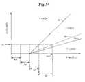
- FIG. 2is a schematic graph that describes the relationship between RF power to tissue (P), flow rate of saline (Q), and tissue temperature (T) when heat conduction to adjacent tissue is considered;
- FIG. 2Ais a schematic graph that describes the relationship between RF power to tissue (P), flow rate of saline (Q), and tissue temperature (T) when the heat required to warm the tissue to the peak temperature (T) 68 is considered;
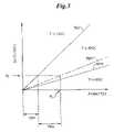
- FIG. 3is schematic graph that describes the relationship between RF power to tissue (P), flow rate of saline (Q), and tissue temperature (T) when heat conduction to adjacent tissue is neglected;
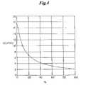
- FIG. 4is a graph showing the relationship of percentage saline boiling and saline flow rate (cc/min) for an exemplary RF generator output of 75 watts;
- FIG. 5is a schematic graph that describes the relationship of load impedance (Z, in ohms) and generator output power (P, in watts), for an exemplary generator output of 75 watts in a bipolar mode;
- FIG. 6is a schematic graph that describes the relationship of time (t, in seconds) and tissue impedance (Z, in ohms) after RF activation;
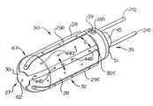
- FIG. 7is a schematic perspective view of a viewing scope with an electrosurgical device according to one embodiment of the invention.
- FIG. 8is a schematic close-up view of the distal end portion of the viewing scope of FIG. 7 bounded by circle A with an electrosurgical device according to one embodiment of the invention
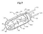
- FIG. 9is a schematic close-up front perspective view of an electrosurgical device according to one embodiment of the invention.
- FIG. 10is a schematic partially exploded close-up rear perspective view of the electrosurgical device of FIG. 9 ;
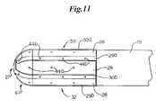
- FIG. 11is a schematic close-up side view of the electrosurgical device of FIG. 9 as part of a medical device assembly
- FIG. 12is a schematic close-up cross-sectional view of the assembly of FIG. 11 taken in accordance with line 12 - 12 of FIG. 13 ;
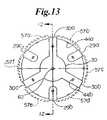
- FIG. 13is a schematic close-up front view of the electrosurgical device of FIG. 9 ;
- FIG. 14is a schematic close-up rear view of the electrosurgical device of FIG. 9 with member 51 removed;
- FIG. 15is a schematic close-up cross-sectional view of the electrosurgical device of FIG. 9 taken in accordance with line 15 - 15 of FIG. 12 ;
- FIG. 16is a schematic close-up cross-sectional view of the electrosurgical device of FIG. 9 taken in accordance with line 16 - 16 of FIG. 12 ;
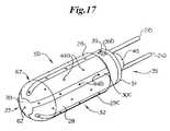
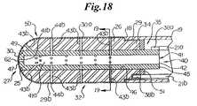
- FIG. 17is a schematic close-up front perspective view of an electrosurgical device according to another embodiment of the invention.
- FIG. 18is a schematic close-up cross-sectional view of the assembly of the electrosurgical device of FIG. 17 and tube 19 taken in accordance with line 12 - 12 of FIG. 13 ;
- FIG. 19is a schematic close-up cross-sectional view of the electrosurgical device of FIG. 17 taken in accordance with line 19 - 19 of FIG. 18 ;
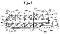
- FIG. 20is a schematic close-up front perspective view of an electrosurgical device according to another embodiment of the invention.
- FIG. 21is a schematic close-up cross-sectional view of the assembly of the electrosurgical device of FIG. 20 and tube 19 taken in accordance with line 12 - 12 of FIG. 13 ;
- FIG. 22is a schematic close-up cross-sectional view of the electrosurgical device of FIG. 20 taken in accordance with line 22 - 22 of FIG. 21 ;
- FIG. 23is a schematic close-up partial cross-sectional view of an electrosurgical device according to another embodiment of the invention taken in accordance with line 22 - 22 of FIG. 21 ;
- FIG. 24is a schematic close-up cross-sectional view of the assembly of an electrosurgical device according to another embodiment of the invention and tube 19 taken in accordance with line 12 - 12 of FIG. 13 ;
- FIG. 25is a schematic close-up partial cross-sectional view of an electrosurgical device according to another embodiment of the invention taken in accordance with line 22 - 22 of FIG. 21 ;
- FIG. 26is a schematic close-up partial cross-sectional view of an electrosurgical device according to another embodiment of the invention taken in accordance with line 22 - 22 of FIG. 21 ;
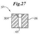
- FIG. 27is a schematic close-up partial cross-sectional view of an electrosurgical device according to another embodiment of the invention taken in accordance with line 22 - 22 of FIG. 21 ;
- FIG. 28is a schematic close-up partial cross-sectional view of an electrosurgical device according to another embodiment of the invention taken in accordance with line 22 - 22 of FIG. 21 ;
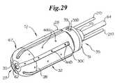
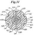
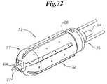
- FIG. 29is a schematic close-up front perspective view of an electrosurgical device according to another embodiment of the invention.
- FIG. 30is a schematic close-up cross-sectional view of the assembly of the electrosurgical device of FIG. 29 and tube 19 taken in accordance with line 12 - 12 of FIG. 13 ;
- FIG. 31is a schematic close-up cross-sectional view of the electrosurgical device of FIG. 29 taken in accordance with line 31 - 31 of FIG. 30 ;
- FIG. 32is a schematic close-up front perspective view of the electrosurgical device of FIG. 29 with instrument 64 extended;
- FIG. 33is a schematic close-up cross-sectional view of the assembly of FIG. 30 with instrument 64 extended;
- FIG. 34is a schematic close-up front perspective view of an electrosurgical device according to another embodiment of the invention.
- FIG. 35is a schematic close-up cross-sectional view of the assembly of the electrosurgical device of FIG. 34 and tube 19 taken in accordance with line 12 - 12 of FIG. 13 ;
- FIG. 36is a schematic close-up cross-sectional view of the electrosurgical device of FIG. 34 taken in accordance with line 36 - 36 of FIG. 35 ;
- FIG. 37is a schematic close-up front perspective view of an electrosurgical device according to another embodiment of the invention.
- FIG. 38is a schematic close-up cross-sectional view of the electrosurgical device of FIG. 37 taken in accordance with line 38 - 38 of FIG. 39 ;
- FIG. 39is a schematic close-up cross-sectional view of the assembly of the electrosurgical device of FIG. 37 with instrument 64 and tube 19 taken in accordance with line 12 - 12 of FIG. 13 ;
- FIG. 40is a schematic close-up cross-sectional view of the assembly of the electrosurgical device of FIG. 37 with instrument 73 and tube 19 taken in accordance with line 12 - 12 of FIG. 13 ;
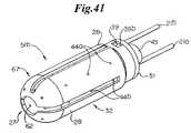
- FIG. 41is a schematic close-up front perspective view of an electrosurgical device according to another embodiment of the invention.
- FIG. 42is a schematic close-up cross-sectional view of the assembly of the electrosurgical device of FIG. 41 and tube 19 taken in accordance with line 12 - 12 of FIG. 13 ;
- FIG. 43is a schematic close-up cross-sectional view of the electrosurgical device of FIG. 42 taken in accordance with line 43 - 43 of FIG. 42 ;
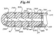
- FIG. 44is a schematic close-up front perspective view of an electrosurgical device according to another embodiment of the invention.
- FIG. 45is a schematic close-up rear perspective view of the electrosurgical device of FIG. 44 with member 51 removed;
- FIG. 46is a schematic close-up cross-sectional view of the assembly of the electrosurgical device of FIG. 44 and tube 19 taken in accordance with line 12 - 12 of FIG. 13 ;
- FIG. 47is a schematic close-up cross-sectional view of the electrosurgical device of FIG. 44 taken in accordance with line 47 - 47 of FIG. 46 ;
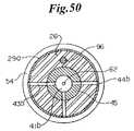
- FIG. 48is a schematic close-up front perspective view of an electrosurgical device according to another embodiment of the invention.
- FIG. 49is a schematic close-up cross-sectional view of the assembly of the electrosurgical device of FIG. 48 and tube 19 taken in accordance with line 12 - 12 of FIG. 13 ;
- FIG. 50is a schematic close-up cross-sectional view of the electrosurgical device of FIG. 48 taken in accordance with line 50 - 50 of FIG. 49 ;
- FIG. 51is a schematic close-up front perspective view of an electrosurgical device according to another embodiment of the invention.
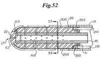
- FIG. 52is a schematic close-up cross-sectional view of the assembly of the electrosurgical device of FIG. 51 and tube 19 taken in accordance with line 12 - 12 of FIG. 13 ;
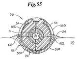
- FIG. 53is a schematic close-up cross-sectional view of the electrosurgical device of FIG. 51 taken in accordance with line 53 - 53 of FIG. 52 ;
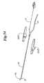
- FIG. 54is a schematic exploded perspective view of an assembly of an electrosurgical device according to another embodiment of the invention and a handle 100 ;
- FIG. 55is the schematic close-up up cross-sectional view of FIG. 53 shown with tissue 20 and with fluid 24 ;
- FIG. 56is the schematic close-up up cross-sectional view of FIG. 21 shown with tissue 20 and with fluid 24 ;
- FIG. 57is a schematic close-up front perspective view of an electrosurgical device according to another embodiment of the invention.
- FIG. 58is a schematic close-up rear perspective view of the electrosurgical device of FIG. 57 with member 51 removed;
- FIG. 59is a schematic close-up cross-sectional view of the assembly of the electrosurgical device of FIG. 57 and tube 19 taken in accordance with line 12 - 12 of FIG. 13 ;
- FIG. 60is a schematic close-up cross-sectional view of the electrosurgical device of FIG. 57 taken in accordance with line 60 - 60 of FIG. 59 ;
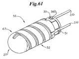
- FIG. 61is a schematic close-up front perspective view of an electrosurgical device according to another embodiment of the invention.
- FIG. 62is a schematic close-up rear perspective view of the electrosurgical device of FIG. 61 with member 51 removed;
- FIG. 63is a schematic close-up cross-sectional view of the assembly of the electrosurgical device of FIG. 61 and tube 19 taken in accordance with line 12 - 12 of FIG. 13 ;
- FIG. 64is a schematic close-up cross-sectional view of the assembly of the electrosurgical device of FIG. 61 and tube 19 taken at 90 degrees to line 12 - 12 of FIG. 13 ;
- FIG. 65is a schematic close-up cross-sectional view of the electrosurgical device of FIG. 61 taken in accordance with line 65 - 65 of FIG. 63 .
- the inventionprovides systems, devices and methods that preferably improve control of tissue temperature at a tissue treatment site during a medical procedure.
- the inventionis particularly useful during surgical procedures upon tissues of the body, where it is desirable to shrink tissue, coagulate fluids (e.g. oozing blood), and at least partially occlude lumens, vessels (e.g. lumen of blood vessels (e.g. arteries, veins), intestines (e.g. absorbent vessels)) and airways (e.g. trachea, bronchi, bronchiole)).
- tissuee.g. oozing blood
- vesselse.g. lumen of blood vessels (e.g. arteries, veins), intestines (e.g. absorbent vessels)
- airwayse.g. trachea, bronchi, bronchiole
- the inventionpreferably involves the use of electrosurgical procedures, which preferably utilize RF power and electrically conductive fluid to treat tissue.
- a desired tissue temperature rangeis achieved through adjusting parameters, such as conductive fluid flow rate, that affect the temperature at the tissue/electrode interface.
- the deviceachieves a desired tissue temperature utilizing a desired percentage boiling of the conductive solution at the tissue/electrode interface.
- the inventionprovides a control device, the device comprising a flow rate controller that receives a signal indicating power applied to the system, and adjusts the flow rate of conductive fluid from a fluid source to an electrosurgical device.
- a control systemcomprising a flow rate controller, a measurement device that measures power applied to the system, and a pump that provides fluid at a selected flow rate.
- FIG. 1shows a block diagram of one exemplary embodiment of a system of the invention.
- an electrically conductive fluidis provided from a fluid source 1 , through a fluid line 2 , to a pump 3 , which has an outlet fluid line 4 a that is connected as an input fluid line 4 b to electrosurgical device 5 .
- the outlet fluid line 4 a and the input fluid line 4 bare flexible and comprise a polymer, such as polyvinylchloride (PVC), while the conductive fluid comprises a saline solution. More preferably, the saline comprises sterile, and even more preferably, normal saline.
- PVCpolyvinylchloride
- the conductive fluidmay comprise hypertonic saline solution, hypotonic saline solution, Ringers solution (a physiologic solution of distilled water containing specified amounts of sodium chloride, calcium chloride, and potassium chloride), lactated Ringer's solution (a crystalloid electrolyte sterile solution of distilled water containing specified amounts of calcium chloride, potassium chloride, sodium chloride, and sodium lactate), Locke-Ringer's solution (a buffered isotonic solution of distilled water containing specified amounts of sodium chloride, potassium chloride, calcium chloride, sodium bicarbonate, magnesium chloride, and dextrose), or any other electrolyte solution.
- the fluidmay also comprise an electrically non-conductive fluid.
- the use of a non-conductive fluidis less preferred to that of a conductive fluid as the non-conductive fluid does not conduct electricity.
- the use of a non-conductive fluidstill provides certain advantages over the use of a dry electrode including, for example, reduced occurrence of tissue sticking to the electrode. Therefore, it is also within the scope of the invention to include the use of a non-conducting fluid, such as, for example, dionized water.
- Energy to heat tissueis provided from energy source, such as an electrical generator 6 which preferably provides RF alternating current energy via a cable 7 to energy source output measurement device, such as a power measurement device 8 that measures the RF alternating current electrical power.
- energy sourcesuch as an electrical generator 6 which preferably provides RF alternating current energy via a cable 7 to energy source output measurement device, such as a power measurement device 8 that measures the RF alternating current electrical power.
- the power measurement device 8does not turn the power off or on, or alter the power in any way.
- a power switch 15 connected to the generator 6is preferably provided by the generator manufacturer and is used to turn the generator 6 on and off.
- the power switch 15can comprise any switch to turn the power on and off, and is commonly provided in the form of a footswitch or other easily operated switch, such as a switch 15 a mounted on the electrosurgical device 5 .
- the power switch 15 or 15 amay also function as a manually activated device for increasing or decreasing the rate of energy provided from the surgical device 5 .
- internal circuitry and other components of the generator 6may be used for automatically increasing or decreasing the rate of energy provided from the surgical device 5 .
- a cable 9preferably carries RF energy from the power measurement device 8 to the electrosurgical device 5 . Power, or any other energy source output, is preferably measured before it reaches the electrosurgical device 5 .
- power Por the rate of energy delivery (e.g. joules/sec)
- I ⁇ Vcurrent times voltage
- I 2 ⁇ Rcurrent squared times resistance
- V 2 /Rvoltage squared divided by the resistance
- the current Imay be measured in amperes
- the voltage Vmay be measured in volts
- the electrical resistance Rmay be measured in ohms
- the power Pmay be measured in watts (joules/sec).
- the frequency of the RF electrical energyis preferably provided within a frequency band (i.e. a continuous range of frequencies extending between two limiting frequencies) in the range between and including about 9 kHz (kilohertz) to 300 GHz (gigahertz). More preferably, the RF energy is provided within a frequency band in the range between and including about 50 kHz (kilohertz) to 50 MHz (megahertz). Even more preferably, the RF energy is provided within a frequency band in the range between and including about 200 kHz (kilohertz) to 2 MHz (megahertz).
- RF energyis provided within a frequency band in the range between and including about 400 kHz (kilohertz) to 600 kHz (kilohertz). Further, it should also be understood that, for any frequency band identified above, the range of frequencies may be further narrowed in increments of 1 (one) hertz anywhere between the lower and upper limiting frequencies.
- the electrical energyi.e., energy made available by the flow of electric charge, typically through a conductor or by self-propagating waves
- the electrical energymay comprise any frequency of the electromagnetic spectrum (i.e. the entire range of radiation extending in frequency from 10 23 hertz to 0 hertz) and including, but not limited to, gamma rays, x-rays, ultraviolet radiation, visible light, infrared radiation, microwaves, and any combinations thereof.
- heating of the tissueis preferably performed by means of resistance heating.
- increasing the temperature of the tissue as a result of electric current flow through the tissuewith the electrical energy being absorbed from the voltage and transformed into thermal energy (i.e. heat) via accelerated movement of ions as a function of the tissue's electrical resistance.
- Heating with electrical energymay also be performed by means of dielectric heating (capacitation).
- dielectric heatingcapacitation
- Dielectric lossis the electrical energy lost as heat in the polarization process in the presence of the applied electric field.
- an alternating current fieldthe energy is absorbed from the alternating current voltage and converted to heat during the polarization of the molecules.
- energy provided to heat the tissuemay comprise surgical devices other than electrosurgical devices, energy sources other than generators, energy forms other than electrical energy and mechanisms other than resistance heating.
- energy provided to heat the tissuemay comprise surgical devices other than electrosurgical devices, energy sources other than generators, energy forms other than electrical energy and mechanisms other than resistance heating.
- Suchmay be provided, for example, to the tissue from a heated device, which heats tissue through direct contact with the energy source (conduction), heats through contact with a flowing fluid (convection), or from a remote heat source (radiation).
- providing energy to the tissuemay be provided via mechanical energy which is transformed into thermal energy via accelerated movement of the molecules, such as by mechanical vibration provided, for example, by energy source such as a transducer containing a piezoelectric substance (e.g., a quartz-crystal oscillator) that converts high-frequency electric current into vibrating ultrasonic waves which may be used by, for example, an ultrasonic surgical device.
- energy sourcesuch as a transducer containing a piezoelectric substance (e.g., a quartz-crystal oscillator) that converts high-frequency electric current into vibrating ultrasonic waves which may be used by, for example, an ultrasonic surgical device.
- providing energy to the tissuemay be provided via radiant energy (i.e. energy which is transmitted by radiation/waves) which is transformed into thermal energy via absorption of the radiant energy by the tissue.
- the radiation/wavescomprise electromagnetic radiation/waves which include, but is not limited to, radio waves, microwaves, infrared radiation, visible light radiation, ultraviolet radiation, x-rays and gamma rays. More preferably, such radiant energy comprises energy with a frequency of 3 ⁇ 10 11 hertz to 3 ⁇ 10 16 hertz (i.e. the infrared, visible, and ultraviolet frequency bands of the electromagnetic spectrum).
- the electromagnetic wavesare coherent and the electromagnetic radiation is emitted from energy source such as a laser device.
- a flow rate controller 11preferably includes a selection switch 12 that can be set to achieve desired levels of percentage fluid boiling (for example, 100%, 98%, 80% boiling).
- the flow rate controller 11receives an input signal 10 from the power measurement device 8 and calculates an appropriate mathematically predetermined fluid flow rate based on percentage boiling indicated by the selection switch 12 .
- a fluid switch 13is provided so that the fluid system can be primed (e.g. air eliminated) before turning the generator 6 on.
- the output signal 16 of the flow rate controller 11is preferably sent to the pump 3 motor to regulate the flow rate of conductive fluid, and thereby provide an appropriate fluid flow rate which corresponds to the amount of power being delivered.
- the inventioncomprises a flow rate controller that is configured and arranged to be connected to a source of RF power, and a source of fluid, for example, a source of conductive fluid.
- the device of the inventionreceives information about the level of RF power applied to an electrosurgical device, and adjusts the flow rate of the fluid to the electrosurgical device, thereby controlling temperature at the tissue treatment site.
- elements of the systemare physically included together in one electronic enclosure.
- One such embodimentis shown by enclosure within the outline box 14 of FIG. 1 .
- the pump 3 , flow rate controller 11 , and power measurement device 8are enclosed within an enclosure, and these elements are connected through electrical connections to allow signal 10 to pass from the power measurement device 8 to the flow rate controller 11 , and signal 16 to pass from the flow rate controller 11 to the pump 3 .
- Other elements of a systemcan also be included within one enclosure, depending upon such factors as the desired application of the system, and the requirements of the user.
- the pump 3can be any suitable pump used in surgical procedures to provide saline or other fluid at a desired flow rate.
- the pump 3comprises a peristaltic pump.
- a rotary peristaltic pumptypically a fluid is conveyed within the confines of a flexible tube by waves of contraction placed externally on the tube which are produced mechanically, typically by rotating rollers which squeeze the flexible tubing against a support intermittently.
- a linear peristaltic pumptypically a fluid is conveyed within the confines of a flexible tube by waves of contraction placed externally on the tube which are produced mechanically, typically by a series of compression fingers or pads which squeeze the flexible tubing against a support sequentially.
- Peristaltic pumpsare generally preferred for use as the electro-mechanical force mechanism (e.g. rollers driven by electric motor) does not make contact the fluid, thus reducing the likelihood of inadvertent contamination.
- pump 3can be a “syringe pump”, with a built-in fluid supply.
- a filled syringeis located on an electromechanical force mechanism (e.g. ram driven by electric motor) which acts on the plunger of the syringe to force delivery of the fluid contained therein.
- the syringe pumpmay comprise a double-acting syringe pump with two syringes such that they can draw saline from a reservoir, either simultaneously or intermittently.
- the pumping mechanismis generally capable of both infusion and withdrawal.
- fluidsuch as conductive fluid
- IVintravenous
- fluid from a fluid sourcesuch as an IV bag can be provided through an IV flow controller that may provide a desired flow rate by adjusting the cross sectional area of a flow orifice (e.g. lumen of the connective tubing with the electrosurgical device) while sensing the flow rate with a sensor such as an optical drop counter.
- fluid from a fluid sourcesuch as an IV bag an be provided through a manually or automatically activated device such as a flow controller, such as a roller clamp, which also adjusts the cross sectional area of a flow orifice and may be adjusted manually by, for example, the user of the device in response to their visual observation (e.g. fluid boiling) at the tissue treatment site or a pump.
- a manually or automatically activated devicesuch as a flow controller, such as a roller clamp, which also adjusts the cross sectional area of a flow orifice and may be adjusted manually by, for example, the user of the device in response to their visual observation (e.g. fluid boiling) at the tissue treatment site or a pump.
- pump 3may include other types of infusion and withdrawal pumps.
- pump 3may comprise pumps which may be categorized as piston pumps, rotary vane pumps (e.g. blower, axial impeller, centrifugal impeller), cartridge pumps and diaphragm pumps.
- the pumpcan be substituted with any type of flow controller, such as a manual roller clamp used in conjunction with an IV bag, or combined with the flow controller to allow the user to control the flow rate of conductive fluid to the device.
- a valve configurationcan be substituted for pump 3 .
- the fluid source 1 pump 3 , generator 6 , power measurement device 8 or flow rate controller 11 , or any other components of the system not expressly recited abovemay comprise a portion of the electrosurgical device 5 .
- the fluid sourcemay comprise a compartment of the electrosurgical device 5 which contains fluid, as indicated at reference character 1 a .
- the compartmentmay be detachably connected to the electrosurgical device 5 , such as a canister which may be attached via threaded engagement with the device 5 .
- the compartmentmay be configured to hold a pre-filled cartridge of fluid, rather than the fluid directly.
- energy sourcesuch as a direct current (DC) battery used in conjunction with inverter circuitry and a transformer to produce alternating current at a particular frequency
- energy sourcemay comprise a portion of the electrosurgical device 5 , as indicated at reference character 6 a .
- the battery element of the energy sourcemay comprise a rechargeable battery.
- the battery elementmay be detachably connected to the electrosurgical device 5 , such as for recharging.
- the flow rate controller 11controls the rate of flow from the fluid source 1 .
- the rate of fluid flow from the fluid source 1is based upon the amount of RF power provided from the generator 6 to the electrosurgical device 5 .
- the rate of fluid flow and the RF powermay be expressed as a direct, linear relationship.
- the flow rate of conductive fluidsuch as saline, interacts with the RF power and various modes of heat transfer away from the target tissue, as described herein.
- boiling point of salinewhen the terms “boiling point of saline”, “vaporization point of saline”, and variations thereof are used, what is intended is the boiling point of the water in the saline solution.
- FIG. 2shows a schematic graph that describes the relationship between the flow rate of saline, RF power to tissue, and regimes of boiling as detailed below.
- the peak tissue temperaturecan be estimated, and once tissue temperature is estimated, it follows directly whether it is hot enough to boil saline.
- P⁇ T/R+ ⁇ c ⁇ Q 1 ⁇ T+ ⁇ Q b h v (1)
- Pthe total RF electrical power that is converted into heat.
- RF power to tissueis represented on the X-axis as P (watts) and flow rate of saline (cc/min) is represented on the Y-axis as Q.
- Pwatts
- Qflow rate of saline
- Qflow rate of saline
- This offsetis the heat conducted to adjacent tissue. For example, using the calculation above for bipolar forceps, this offset RF power is about 10.5 watts. If the power is increased above this level with no saline flow, the peak tissue temperature can rise well above 100° C., resulting in tissue desiccation from the boiling off of water in the cells of the tissue.
- Equation (1)The second term [ ⁇ c ⁇ Q 1 ⁇ T] in equation (1) is heat used to warm up the flow of saline without boiling the saline, represented as 72 in FIG. 2 , where:
- This equationdefines the line shown in FIG. 2 as the line of onset of boiling 76 .
- the most significant factor contributing to heat transfer from a wet electrode devicecan be fractional boiling. The present invention recognizes this fact and exploits it.
- tissue desiccationAs indicated previously in the specification, using a fluid to couple energy to tissue inhibits such undesirable effects as sticking, desiccation, smoke production and char formation, and that one key factor is inhibiting tissue desiccation, which occur if the tissue temperature exceeds 100° C. and all the intracellular water boils away, leaving the tissue extremely dry and much less electrically conductive.
- one control strategy or mechanism which can be employed for the electrosurgical device 5is to adjust the power P and flow rate Q such that the power P used at a corresponding flow rate Q is equal to or less than the power P required to boil 100% of the fluid and does not exceed the power P required to boil 100% of the fluid.
- this control strategytargets not using the electrosurgical device 5 only in the region of FIG. 2 identified as T>>100° C.
- Another control strategy that can be used for the electrosurgical device 5is to operate the device 5 in the region T ⁇ 100° C., but at high enough temperature to shrink tissue containing Type I collagen (e.g., walls of blood vessels, bronchi, bile ducts, etc.), which shrinks when exposed to about 85° C. for an exposure time of 0.01 seconds, or when exposed to about 65° C. for an exposure time of 15 minutes.
- An exemplary target temperature/time for tissue shrinkageis about 75° C. with an exposure time of about 1 second.
- a determination of the high end of the scalei.e., when the fluid reaches 100° C.
- thermochromic materialsuch as a thermochromic dye (e.g., leuco dye)
- the dyecan be formulated to provide a first predetermined color to the fluid at temperatures below a threshold temperature, such as 75° C., then, upon heating above 75° C., the dye provides a second color, such as clear, thus turning the fluid clear (i.e. no color or reduction in color).
- This color changemay be gradual, incremental, or instant.
- a change in the color of the fluidfrom a first color to a second color (or lack thereof) provides a visual indication to the user of the electrosurgical device 5 as to when a threshold fluid temperature below boiling has been achieved.
- Thermochromic dyesare available, for example, from Color Change Corporation, 1740 Cortland Court, Unit A, Addison, Ill. 60101.
- the above mechanismi.e., a change in the color of the fluid due to a dye
- An exemplary target temperature/time for tissue necrosisis about 55° C. for an exposure time of about 1 second.
- control strategy which may be employed for the electrosurgical device 5is to adjust the power P and flow rate Q such that the power P used at a corresponding flow rate Q is equal to or more than the power P required to initiate boiling of the fluid, but still less than the power P required to boil 100% of the fluid.
- this control strategytargets use using the electrosurgical device 5 on or between the lines of the onset of boiling 76 and 100% boiling line 80 , and not using the electrosurgical device 5 in the regions of FIG. 2 identified as T ⁇ 100° C. and T>>100° C.
- saline flow rateit is desirable to control the saline flow rate so that it is always on a “line of constant % boiling” as, for example, the line of the onset of boiling 76 or the 100% boiling line 80 or any line of constant % boiling located in between (e.g. 50% boiling line 78 ) as shown in FIG. 2 .
- another control strategy that can be used for the electrosurgical device 5is to adjust power P and flow rate Q such that the power P used at a corresponding flow rate Q targets a line of constant % boiling.
- any line of constant % boilingis known.
- the slope of the lineis given by ( ⁇ c ⁇ ⁇ T), while the slope of the 100% boiling line 80 is given by 1/( ⁇ c ⁇ ⁇ T+ph v ).
- the slopeis given by 1/( ⁇ c ⁇ ⁇ T+ ⁇ h v 0.5).
- boiling of the fluidis not detected, such indicates that the temperature is less than 100° C. as indicated in the area of FIG. 2 , and the flow rate Q must be decreased to initiate boiling.
- the flow rate Qmay then decreased until boiling of the fluid is first detected, at which time the line of the onset of boiling 76 is transgressed and the point of transgression on the line 76 is determined. From the determination of a point on the line of the onset of boiling 76 for a particular power P and flow rate Q, and the known slope of the line 76 as outlined above (i.e. 1/ ⁇ c ⁇ ⁇ T), it is also possible to determine the heat conducted to adjacent tissue 70 .
- boiling of the fluidis detected, such indicates that the temperature is approximately equal to 100° C. as indicated in the areas of FIG. 2 , and the flow rate Q must be increased to reduce boiling until boiling stops, at which time the line of the onset of boiling 76 is transgressed and the point of transgression on the line 76 determined.
- the flow rate Qmust be increased to reduce boiling until boiling stops, at which time the line of the onset of boiling 76 is transgressed and the point of transgression on the line 76 determined.
- phase changei.e. from liquid to vapor or vice-versa
- a sensorwhich preferably senses either an absolute change (e.g. existence or non-existence of boiling with binary response such as yes or no) or a change in a physical quantity or intensity and converts the change into a useful input signal for an information-gathering system.
- the phase change associated with the onset of boilingmay be detected by a pressure sensor, such as a pressure transducer, located on the electrosurgical device 5 .
- the phase change associated with the onset of boilingmay be detected by a temperature sensor, such as a thermistor or thermocouple, located on the electrosurgical device 5 , such as adjacent to the electrode.
- the phase change associated with the onset of boilingmay be detected by a change in the electric properties of the fluid itself. For example, a change in the electrical resistance of the fluid may be detected by an ohm meter; a change in the amperage may be measured by an amp meter; as change in the voltage may be detected by a volt meter; and a change in the power may be determined by a power meter.
- Yet another control strategy which may be employed for the electrosurgical device 5is to eliminate the heat conduction term of equation (1) (i.e. ⁇ T/R). Since the amount of heat conducted away to adjacent tissue can be difficult to precisely predict, as it may vary, for example, by tissue type, it may be preferable, from a control point of view, to assume the worst case situation of zero heat conduction, and provide enough saline so that if necessary, all the RF power could be used to heat up and boil the saline, thus providing that the peak tissue temperature will not go over 100° C. a significant amount. This situation is shown in the schematic graph of FIG. 3 .
- the equation of the line for any line of constant % boilingis known.
- the 98% boiling line, 80% boiling line, etc.can be determined in response to a corresponding input from the selection switch 12 .
- the input from the selection switchpreferably may comprise any percentage of boiling.
- the percentage of boilingmay be selected in single percent increments (i.e. 100%, 99%, 98%, etc.).
- the flow rate controller 11Upon determination of the line of the onset of boiling 76 , the 100% boiling line 80 or any line of constant % boiling there between, it is generally desirable to control the flow rate Q so that it is always on a particular line of constant % boiling for consistent tissue effect. In such a situation, the flow rate controller 11 will adjust the flow rate Q of the fluid to reflect changes in power P provided by the generator 6 , as discussed in greater detail below. For such a use the flow rate controller may be set in a line of constant boiling mode, upon which the % boiling is then correspondingly selected.
- the saline flow rate Qit is desirable to control the saline flow rate Q so that it is always on a line of constant % boiling for consistent tissue effect.
- the preferred line of constant % boilingmay vary based on the type of electrosurgical device 5 . For example, if the device is a monopolar stasis device and shunting through saline is not an issue, then it can be preferable to operate close to or directly on, but not over the line of the onset of boiling, such as 76 a in FIG. 3 . This preferably keeps tissue as hot as possible without causing desiccation.
- the present inventionprovides a method of controlling boiling of fluid, such as a conductive fluid, at the tissue/electrode interface.
- thisprovides a method of treating tissue without use of tissue sensors, such as temperature or impedance sensors.
- the inventioncan control boiling of conductive fluid at the tissue/electrode interface and thereby control tissue temperature without the use of feedback loops.
- the inclusion of the heat required to warm the tissue to the peak temperature (T) in the control strategyis graphically represented at 68 in FIG. 2A .
- the effects of the heat required to warm the tissue to the peak temperature (T) 68should be taken into account before flow rate Q adjustment being undertaken to detect the location of the line of onset of boiling 76 .
- the flow rate Qshould not be decreased in response to a lack of boiling before at least a quasi-steady state has been achieved as the location of the line of onset of boiling 76 will continue to move during the transitory period.
- FIG. 4shows an exemplary graph of flow rate Q versus % boiling for a situation where the RF power P is 75 watts.
- the percent boilingis represented on the X-axis
- the saline flow rate Q (cc/min)is represented on the Y-axis.
- the most desirable predetermined saline flow rate Qis 2 cc/min.
- flow rate Q versus % boiling at the remaining points of the graftillustrates a non-linear relationship as follows:
- Typical RF generators used in the fieldhave a power selector switch to 300 watts of power, and on occasion some have been found to be selectable up to 400 watts of power.
- the calculated flow rate Qis 69.7 cc/min and with a corresponding power of 400 watts the calculated flow rate Q is 92.9 cc/min.
- a fluid flow rate Qof about 100 cc/min or less with the present invention is expected to suffice for the vast majority of applications.
- the schematic graph of FIG. 5shows the general trends of the output curve of a typical general-purpose generator, with the output power changing as load (tissue plus cables) impedance Z changes.
- Load impedance Z(in ohms) is represented on the X-axis
- generator output power P(in watts) is represented on the Y-axis.
- the electrosurgical power(RF) is set to 75 watts in a bipolar mode.
- the powerwill remain constant as it was set as long as the impedance Z stays between two cut-offs, low and high, of impedance, that is, for example, between 50 ohms and 300 ohms in the illustrated embodiment.
- the power Pwill decrease, as shown by the low impedance ramp 82 a .
- the power Pwill decrease, as shown by the high impedance ramp 82 b .
- the low impedance cut-off(low impedance ramp 82 a ), where power starts to ramp down as impedance Z drops further. This change in output is invisible to the user of the generator and not evident when the generator is in use, such as in an operating room.
- FIG. 6shows the general trend of how tissue impedance generally changes with time for saline-enhanced electrosurgery.
- the temperature coefficient of the tissue and saline in the cellsis such that the tissue impedance decreases until a steady-state temperature is reached upon which time the impedance remains constant.
- the load impedance Zdecreases, potentially approaching the impedance Z cut-off of 50 ohms. If tissue is sufficiently heated, such that the low impedance cut-off is passed, the power P decreases along the lines of the low impedance ramp 82 a of FIG. 5 .
- the control devicereceives a signal indicating the drop in actual power delivered to the tissue and adjusts the flow rate Q of saline to maintain the tissue/electrode interface at a desired temperature.
- the drop in actual power P deliveredis sensed by the power measurement device 8 (shown in FIG. 1 ), and the flow rate Q of saline is decreased by the flow rate controller 11 (also shown in FIG. 1 ).
- this reduction in saline flow rate Qallows the tissue temperature to stay as hot as possible without desiccation. If the control device was not in operation and the flow rate Q allowed to remain higher, the tissue would be over-cooled at the lower power input. This would result in decreasing the temperature of the tissue at the treatment site.
- the flow rate controller 11 of FIG. 1can be a simple “hard-wired” analog or digital device that requires no programming by the user or the manufacturer.
- the flow rate controller 11can alternatively include a processor, with or without a storage medium, in which the determination procedure is performed by software, hardware, or a combination thereof.
- the flow rate controller 11can include semi-programmable hardware configured, for example, using a hardware descriptive language, such as Verilog.
- the flow rate controller 11 of FIG. 1is a computer, microprocessor-driven controller with software embedded.
- the flow rate controller 11can include additional features, such as a delay mechanism, such as a timer, to automatically keep the saline flow on for several seconds after the RF is turned off to provide a post-coagulation cooling of the tissue or “quench,” which can increase the strength of the tissue seal. Also, in another embodiment, the flow rate controller 11 can include a delay mechanism, such as a timer, to automatically turn on the saline flow several seconds before the RF is turned on to inhibit the possibility of undesirable effects as sticking, desiccation, smoke production and char formation.
- a delay mechanismsuch as a timer
- the flow rate controller 11can include a low level flow standby mechanism, such as a valve, which continues the saline flow at a standby flow level (which prevents the flow rate from going to zero when the RF power is turned off) below the surgical flow level ordinarily encountered during use of the electrosurgical device 5 .
- a low level flow standby mechanismsuch as a valve, which continues the saline flow at a standby flow level (which prevents the flow rate from going to zero when the RF power is turned off) below the surgical flow level ordinarily encountered during use of the electrosurgical device 5 .
- FIG. 9An exemplary electrosurgical device of the present invention which may be used in conjunction with the system of the present invention is shown at reference character 5 a in FIG. 9 , and more particularly in FIGS. 7-16 . While various electrosurgical devices of the present invention are described with reference to use with the remainder of the system of the invention, it should be understood that the description of the combination is for purposes of illustrating the remainder of the system of the invention only. Consequently, it should be understood that the electrosurgical devices of the present invention can be used alone, or in conjunction with the remainder of the system of the invention, or that a wide variety of electrosurgical devices can be used in connection with the remainder of the system of the invention.
- electrosurgical device 5 ais preferably used in conjunction with a viewing scope, shown as an endoscope as illustrated at reference character 17 , during a minimally invasive procedure such flexible endoscopic gastrointestinal surgery.
- the endoscope 17preferably comprises an elongated flexible shaft portion 17 a , though device 5 a may be used with rigid shaft viewing scopes, for example, during laparoscopic surgery.
- Endoscope 17also comprises a proximal portion 17 b separated from a distal portion 17 c by shaft portion 17 a .
- Proximal portion 17 b of endoscope 17preferably comprises a control head portion 17 d .
- Control head portion 17 dpreferably comprises a tissue treatment site viewer 17 e and one or more directional control knobs 17 f and 17 g to control the movement of the flexible distal portion 17 c of flexible shaft 17 a .
- Control knob 17 fpreferably comprises a right/left angulation control knob while control knob 17 g preferably comprises an up/down angulation control knob.
- flexible shaft 17 ahouses at least one device channel 17 h through which surgical device 5 a may be passed. Also as shown, flexible shaft 17 a also preferably contains at least one viewing channel 17 i to enable viewing through the distal portion 17 c . Flexible shaft 17 a also preferably contains at least one fluid flow channel 17 j for providing liquid (e.g. water) or gas (e.g. air) to a tissue treatment site. Also preferably, electrosurgical device 5 a is configured to extend from the distal end portion 17 c , and more preferably, the distal end surface 17 k of endoscope 17 , as shown in FIG. 8 .
- liquide.g. water
- gase.g. air
- electrosurgical device 5 ais preferably assembled (e.g. mechanically connected via press-fit, mechanical connector, welded, adhesively bonded) adjacent the distal end 18 of a long, hollow, tube 19 to preferably form a medical device assembly.
- Tube 19is preferably self-supporting and flexible, and more preferably comprises a catheter which may be flexed to apply tamponade (e.g. compressive force) through the electrosurgical device 5 a to a bleeding source in the gastrointestinal tract
- Electrosurgical device 5 ain combination with a catheters, may be referred to as a catheter assembly.
- electrosurgical device 5 ais also preferably electrically connected to the conductors 38 a , 38 b of insulated electrical wires 21 a , 21 b , respectively, which have been passed through lumen 23 of tube 19 as branches of cable 9 which is connected to generator 6 .
- the tube 19may incorporate the conductors 38 a , 38 b of wires 21 a , 21 b in the tube wall (in essence creating a multi-lumen tube comprising three lumens where two of the lumens are occupied exclusively by the conductors 38 a , 38 b of wires 21 a , 21 b ) to reduce the complexity of items being passed down lumen 23 .
- electrosurgical device 5 aalong with the flexible tube 19 and wires 21 a , 21 b contained therein may enter channel entrance opening 171 of device channel 17 h and are thereafter passed through and along at least a portion of the length of device channel 17 h until exiting from channel exit opening 17 m.
- electrosurgical device 5 acomprises a probe body 26 .
- Probe body 26is preferably sized to pass from entrance 171 to the exit 17 m of device channel 17 h of scope 17 .
- Probe body 26may comprise a solid, electrically non-conductive, insulative material impervious to the flow of fluid 24 therethrough including, but not limited to, ceramic or polymer materials.
- non-conductive polymer materialsinclude, but are not limited to, polyamide (a/k/a nylon), polyphthalamide (PPA), polyamideimide (PAI), polyetherimide (PEI), polyetheretherketone (PEEK), polyphenylenesulfide (PPS), polysulfone (PSO), polyethersulfone (PES), syndiotactic polystyrene (SPS), polyimide (PI) or any other non-conductive polymer, thermoplastic or thermoset.
- Probe body 26may also comprise a liquid crystal polymer and, more particularly, an aromatic liquid crystal polyester which is reinforced with glass fiber, such as Vectra® A130 from Ticona, 90 Morris Avenue, Summit, N.J. 07901-3914.
- probe body 26may comprise a machinable ceramic material such as sold under the tradename MACOR.
- the non-conductive material of the probe body 26may be coated with a non-conductive, lubricating or non-stick coating, such as polytetrafluoroethylene (PTFE).
- PTFEpolytetrafluoroethylene
- electrosurgical device 5 ais greatly enlarged since, for example, in one exemplary embodiment the cross-sectional dimension of device 5 a , specifically its diameter, is about 7 French (about 2.4 mm or 0.095 inches). In another embodiment, the cross-sectional dimension of electrosurgical device 5 a may be about 10 French (about 3.2 mm or 0.126 inches). In still other embodiments, electrosurgical device 5 a may be configured with any cross-sectional dimension suitable to pass through the working channel of a viewing scope or of a trocar (also known as a cannula) where such a device is required.
- a trocaralso known as a cannula
- electrosurgical device 5 a and, in particular, probe body 26preferably comprise a generally cylindrical shape 32 with the distal end portion of the electrosurgical device 5 a and probe body 26 preferably comprising a generally domed, hemispherical shape 67 , such as that of a semi-circle, which provides a smooth, blunt contour outer surface.
- electrosurgical device 5 apreferably comprises a fluid flow manifold 40 located within probe body 26 .
- Manifold 40preferably comprises a discrete, rectilinear, longitudinally directed, central fluid flow passage 41 , preferably located on-center about longitudinal axis 31 of electrosurgical device 5 a .
- central flow passage 41preferably extends between proximal end 35 and distal end 27 of electrosurgical device 5 a through probe body 26 and has a central flow passage fluid entrance opening 42 located adjacent the proximal end 35 of probe body 26 .
- central flow passage 41preferably extends into and is fluidly coupled with lumen 23 of flexible tube 19 .
- manifold 40preferably comprises at least one discrete, rectilinear, lateral fluid flow passage 43 which is fluidly coupled to central fluid flow passage 41 .
- manifold 40comprises a plurality of discrete, rectilinear, lateral fluid flow passages 43 a , 43 b which are defined and spaced both longitudinally along and circumferentially around the probe body 26 and central fluid flow passage 41 . More preferably the lateral fluid flow passages 43 a , 43 b are defined and spaced from proximal end 35 of electrosurgical device 5 a through probe body 26 to the distal end 27 of electrosurgical device 5 a through probe body 26 .
- lateral fluid flow passages 43 a , 43 bpreferably each have a cross-sectional dimension, more specifically diameter, and corresponding cross-sectional area, less than the portion of central fluid flow passage 41 from which fluid 24 is provided.
- the lateral fluid flow passages 43 a , 43 b which preferably extend through the cylindrical portion 32 of probe body 26are preferably formed substantially at a right angle (e.g. within about 10 degrees of a right angle) to the central fluid flow passage 41 , both longitudinally and circumferentially.
- the lateral fluid flow passages 43 a , 43 bare preferably formed substantially at a right angle to the outer tissue interacting/treating surfaces 28 , 50 of the electrosurgical device 5 a.
- lateral fluid flow passages 43 a , 43 bextend from central fluid flow passage 41 to lateral flow passage fluid exit openings 44 a , 44 b located on surfaces of electrosurgical device 5 a configured for interacting with and treating tissue.
- lateral flow passage fluid exit openings 44 a , 44 bare located on exposed outer surface 28 of probe body 26 , or an exposed outer surface 50 of electrode 29 a - c , 30 a - c , which are discussed in greater detail later in this specification.
- lateral fluid flow passages 43 a , 43 bpreferably are configured to extend from central fluid flow passage 41 to lateral flow passage fluid exit openings 44 a , 44 b located on the outer surface 28 of probe body 26 and outer surface 50 of electrodes 29 a - c , 30 a - c , respectively, such that lateral flow passages 43 a , 43 b and associated fluid exit openings 44 a , 44 b are defined and spaced both longitudinally along and circumferentially around the outer surfaces 28 an 50 of electrosurgical device 5 a , preferably between proximal end 35 of electrosurgical device 5 a and the distal end 27 of electrosurgical device 5 a and probe body 26 .
- central flow passage 41may be lined by a liner 45 , preferably comprising a non-corrosive, impervious (to fluid 24 ), metal tube (e.g. stainless steel tubing) located within a through bore 46 of probe body 26 which extends from proximal end 35 to distal end 27 of electrosurgical device 5 a and probe body 26 .
- a liner 45preferably the outer wall surface of liner 45 contacts the inner surface of bore 46 of probe body 26 and discrete lateral fluid flow passages 43 a , 43 b extend through the wall thereof.
- liner 45may comprise a cylindrical coil spring with the lateral openings provided between the coils of the spring.
- distal wall section 25 of liner 45 adjacent distal end 27 of the electrosurgical device 5 a and probe body 26partially defines the distal end of the wide proximal portion 41 a of the central flow passage 41 (with the proximal end of the distal narrow portion 41 b of the central flow passage 41 defining the remainder of the distal end of the wide portion 41 a of the central flow passage 41 in this embodiment).
- Distal wall section 25 of liner 45also narrows the central flow passage 41 from wide portion 41 a to narrow portion 41 b and defines a narrow central fluid passage exit opening 62 .
- the distal portion of the central flow passage 41comprises a counterbore configuration.
- wide portion 41 a and narrow portion 41 b of central flow passage 41preferably comprise the configuration of a counterbore adjacent the distal end 27 of electrosurgical device 5 a .
- the distal wall section 25inhibits fluid flow from wide portion 41 a through the narrow portion 41 b of the central flow passage 41 .
- distal wall 25inhibits fluid 24 from exiting from the central fluid passage exit opening 62 as compared to a situation where distal wall 25 would not be used and the central flow passage 41 only would consist of wide portion 41 a .
- at least a portion of the distal end of the central flow passage 41is defined by an occlusion (i.e. wall section 25 ) formed by a portion of the electrosurgical device 5 a.
- wall section 25substantially occludes and inhibits fluid 24 from exiting from the central flow passage exit opening 62 .
- occlusion of central flow passage 41 and the corresponding inhibiting of flow from exiting from the central fluid passage exit opening 62 of the central flow passage 41can be considered substantial when the occlusion and corresponding inhibiting of flow results in increased flow from the lateral flow passages 43 a , 43 b .
- the occlusionfunctions as a fluid flow diverter and redirects fluid coming in contact therewith from flowing parallel with the longitudinal axis 31 of central flow passage 41 to flowing radially from the longitudinal axis 31 through lateral flow passages 43 a , 43 b.
- the probe body 26has an outer surface 52 on which at least a portion of one energy providing member is located, overlies and is conneted.
- the energy providing memberpreferably comprises a pair of electrical conductors 29 , 30 which are respectively electrically connected to insulated wires 21 a , 21 b which are ultimately connected to generator 6 .
- Conductors 29 , 30preferably comprise an electrically conductive metal, which is preferably non-corrosive, such as stainless steel or titanium.
- the conductors 29 , 30are preferably configured to provide energy to tissue for hemostatic therapy and/or for tissue treatment of the wall of an anatomical tube.
- Each conductor 29 , 30may be branched into, for example, additional sub-conductors, such as comprising three elongated longitudinally directed strip electrodes 29 a , 29 b , 29 c and 30 a , 30 b , 30 c which will provide energy to treat tissue.
- the electrodesmay be aligned generally parallel with the longitudinal axis 31 on the peripheral surface of the probe body 26 (comprising exposed probe body surfaces 28 and covered probe body surfaces 52 ) and are preferably angularly uniformly distributed, in this embodiment at angular intervals of 60 degrees.
- the electrodes 29 a - c , 30 a - c of conductors 29 and 30are respectively successively spaced from each other by gaps, G.
- the gaps Gare generally at least about twice the widths W of the electrodes at the cylindrical portion 32 of the probe body 26 .
- the gaps Gare about 0.8 mm and the widths W are about 0.4 mm.
- the wider the gap G between the electrodesthe deeper the effect on tissue being treated.
- the electrodes 29 a - c , 30 a - care provided alternating electrical current, so that the electrodes alternate polarity between positive and negative charges, and adjacent electrodes comprises opposite polarities at any given time to create an electrical field with current flow from the positive to negative charge.
- electrodes 29 a - ccomprise a first polarity (e.g. positive)
- electrodes 30 a - ccomprise a second opposite polarity (e.g. negative).
- the plurality of uniformly distributed opposite electrode pairs formed around the longitudinal axis 31create one or more bipolar electrical circuits, with the number of electrode poles generally equal to the number of circuits.
- an electrical arraywhich extends circumferentially around longitudinal axis 31 and device 5 a comprising six bipolar circuits is created between adjacent successive poles as shown by electrical field lines 57 a - f in FIG. 13 .
- Conductors 29 , 30including electrodes 29 a - c , 30 a - c may comprise preformed metal which is then placed on probe body 26 , or formed-in-place metal which comprises a metallic compound which is formed-in-place on the probe body 26 , typically via painting or spraying.
- conductors 29 , 30 and electrodes 29 a - c , 30 a - cmay be formed by first applying metal completely to the outer surfaces 28 and 52 of probe body 26 (such as by dip coating the outer surface in a liquid metal bath) then removing metal in excess of the conductors 29 , 30 and electrodes 29 a - c , 30 a - c from the surface 28 to define the conductors 29 , 30 and electrodes 29 a - c , 30 a - c , such as by the use of a laser.
- Electrodes 5 apreferably at least three sets of opposite electrode poles are provided.
- at least bipolar, and frequently greater, polar tissue contact and electrocoagulationcan be achieved substantially independent of the orientation of the probe body 26 relative to the tissue treatment site.
- front end usee.g. domed portion 67
- sideways usee.g. cylindrical portion 32
- oblique usee.g. combination of domed portion 67 and cylindrical portion 32
- electrodes 29 a - c of conductor 29are preferably electrically coupled to each other at the proximal end 35 of the probe body 26 .
- electrodes 29 a - c of conductor 29are electrically coupled via a conductor 29 which comprises an electrically conductive radial band, preferably located on a radially recessed shoulder 34 of probe body 26 located at the proximal end 35 of probe body 26 .
- the electrical coupling between electrodes 29 a - c and conductor 29is preferably made via radially displaced localized conductive tabs 36 a - c .
- conductor 38 b of insulated wire 21 bis preferably connected to band preferably in a notch 37 formed in the band and in shoulder 34 , where notch 37 is sized to receive conductor 38 b of wire 21 b .
- Conductor 38 b of insulated wire 21 bis preferably connected to a surface 39 of notch 37 via an electrical connector comprising solder (e.g. silver) from soldering.
- electrodes 30 a - c of conductor 30are preferably electrically coupled to each other at the distal end 27 of the electrosurgical device 5 a and probe body 26 .
- electrodes 30 a - c of conductor 30are electrically coupled via a conductor 30 comprising an electrically conductive hub preferably located at the distal end 27 of the electrosurgical device 5 a and probe body 26 .
- a wall section 47 of the conductor 30 overlying wall section 25 of liner 45may also function an occlusion which either partially defines the distal portion of the central flow passage 41 (i.e.
- central flow passage 41comprises a narrow portion 41 b and a central fluid passage exit opening 62 ) or completely defines the distal end of the central flow passage 41 (i.e. where the central flow passage does not continue through the wall section 47 of conductor 30 ), particularly when liner 45 is not occluded at its distal end (i.e. does not include wall section 25 ).
- Conductor 30is preferably electrically coupled to hollow conductive metal liner 45 to which, in turn, conductor 38 a of insulated wire 21 a is preferably connected to a surface of hollow metal liner 45 at the proximal end 35 of probe body 26 via an electrical connector comprising solder (e.g. silver) from soldering.
- an electrical connectorcomprising solder (e.g. silver) from soldering.
- conductor 38 a of insulated wire 21 amay be connected to an inner surface 49 of conductor 30 .
- the plurality of lateral flow passages 43 awhich extend through probe body 26 to fluid exit openings 44 a are defined and spaced along the outer surface 28 of probe body 26 between at least one pair of adjacent electrodes.
- the plurality of lateral flow passage fluid exit openings 44 aare configured to form both longitudinal and circumferential straight rows, and are preferably uniformly spaced relative to one another.
- preferably lateral flow passages 43 aare configured to distribute fluid flow exiting from fluid exit openings 44 a substantially uniformly.
- Lateral flow passages 43 a of this exemplary embodimentpreferably have a cross-sectional dimension (e.g. diameter) in the range between and including about 0.11 mm to 2 mm and more preferably have a diameter in the range between and including about 0.15 mm to 0.2 mm.
- the plurality of lateral flow passages 43 bwhich extend through probe body 26 and at least one electrode 29 a - c , 30 a - c to fluid exit openings 44 b are defined and spaced along the outer surface 50 of electrodes 29 a - c , 30 a - c .
- the plurality of lateral flow passage fluid exit openings 44 bare configured to form both longitudinal and circumferential straight rows, and are preferably uniformly spaced relative to one another.
- preferably lateral flow passages 43 bare configured to distribute fluid flow exiting from fluid exit openings 44 b substantially uniformly.
- Lateral flow passages 44 b of this exemplary embodimentpreferably have a cross-sectional dimension (e.g. diameter) in the range between and including about 0.1 mm to 2 mm and more preferably have a diameter in the range between and including about 0.15 mm to 0.2 mm.
- a cross-sectional dimensione.g. diameter
- electrical device 5 apreferably further comprises a member 51 which comprises a gasket portion 51 a configured to electrically insulate conductors 38 a , 38 b from one another and inhibit a short circuit (i.e. a low resistance, alternate path through which current will flow, often resulting in damage, rather than through the load circuit) from forming between conductors of different electrical potential (e.g. conductors 29 / 38 b with conductors 30 / 38 a ) in the presence of electrically conductive fluid, which would cause electrical current to flow between conductors (e.g.
- Member 51preferably comprises an insulative flexible polymer material, such as an elastomer and, in this embodiment, preferably comprises the geometry of a thin, flat circular member, such as that of a washer. As shown in FIG. 10 , gasket portion 51 a surrounds aperture 51 b through which wire 21 b extends. Thereafter, gasket portion 51 a preferably forms a gasket with the insulator of wire 21 b to inhibits fluid 24 from lumen 23 of tube 19 from contacting conductors 38 b and 29 .
- Member 51also preferably includes a second gasket portion 51 c which surrounds aperture 51 d through which liner 45 extends and thereafter forms a gasket with the outer surface of liner 45 to also inhibit fluid 24 from lumen 23 of tube 19 from contacting conductor 38 b or 29 .
- electrical device 5 amay further comprise a sensor, such as probe body 26 itself, for sensing, for example, temperature, pressure or saline impedance sensor for sensing the phase change associated with the onset of boiling, or which may be located in or on probe body 26 , adjacent an electrode and/or the tissue.
- a sensorsuch as probe body 26 itself, for sensing, for example, temperature, pressure or saline impedance sensor for sensing the phase change associated with the onset of boiling, or which may be located in or on probe body 26 , adjacent an electrode and/or the tissue.
- probe body 26preferably comprises a circular shape with a uniform diameter along the longitudinal length of the cylindrical portion 32 .
- the outer surface 50 of at least a portion of at least one of the electrodes 29 a - c , 30 a - cis stepped up or otherwise protruding relative to an adjacent exposed outer surface 28 of the probe body 26 by the thickness of the electrodes, preferably in a thickness range between and including about 0.01 mm to 2.0 mm and, more preferably, in the range between and including about 0.1 mm to 0.5 mm.
- the outer surface 50 of all of the electrodes 29 a - c , 30 a - cis stepped up relative to an adjacent exposed outer surface 28 of the probe body 26 by the thickness of the electrodes.
- FIG. 17Another exemplary electrosurgical device of the present invention which may be used in conjunction with the system of the present invention is shown at reference character 5 b in FIG. 17 , and more particularly in FIGS. 17-19 .
- at least a portion of at least one of the electrodes 29 a - c , 30 a - cis located in a recess such that the outer surface 50 of the electrodes is flush relative to an adjacent exposed outer surface 28 of the probe body 26 .
- FIG. 19Another exemplary electrosurgical device of the present invention which may be used in conjunction with the system of the present invention is shown at reference character 5 b in FIG. 17 , and more particularly in FIGS. 17-19 .
- FIG. 19at least a portion of at least one of the electrodes 29 a - c , 30 a - c is located in a recess such that the outer surface 50 of the electrodes is flush relative to an adjacent exposed outer surface 28 of the probe body 26 .
- all the electrodes 29 a - c , 30 a - care located in recesses 53 with the depth of the recesses 53 equal to the thickness of the electrodes such that the outer surface 50 of the electrodes 29 a - c , 30 a - c is flush relative to an adjacent exposed outer surface 28 of the probe body 26 .
- device 5 bmay tend to move along the surface of the tissue more easily than 5 a as the surface roughness associated with protruding electrodes is eliminated.
- FIG. 20Another exemplary electrosurgical device of the present invention which may be used in conjunction with the system of the present invention is shown at reference character 5 c in FIG. 20 , and more particularly in FIGS. 20-22 .
- recess 53provides, at least in part, at least one elongated fluid flow channel 54 for fluid 24 .
- preferably at least a portion of at least one of the electrodes 29 a - c , 30 a - cis located in the recess 53 , and preferably such that the outer surface 50 of the electrodes is stepped down or otherwise recessed relative to an adjacent exposed outer surface 28 of the probe body 26 .
- FIG. 22Another exemplary electrosurgical device of the present invention which may be used in conjunction with the system of the present invention is shown at reference character 5 c in FIG. 20 , and more particularly in FIGS. 20-22 .
- recess 53provides, at least in part, at least one elongated fluid flow channel 54 for fluid 24 .
- all the electrodes 29 a - c , 30 a - care located in recesses 53 , with the depth of the recesses 53 greater than the thickness of the electrodes such that the outer surface 50 of the electrodes 29 a - c , 30 a - c is stepped down relative to an adjacent exposed outer surface 28 of the probe body 26 .
- the fluid flow channel 54is preferably provided in the portion of the recess 53 overlying the outer surface 50 of the electrodes 29 a - c , 30 a - c.
- the configuration of the fluid flow channel 54as provided by geometry (e.g. width, depth), the material and/or surface treatment of the probe body 26 , and/or the material and/or surface treatment of the electrodes 29 a - c , 30 a - c , and may be arranged such that surface tension will act to retain fluid collected in the channel 54 where the force of gravity is acting to remove the fluid from the channel 54 .
- the surface tensionmust be balanced against the inhibition of fluid flow from lateral flow passages 43 b . While partial inhibition from lateral flow passages 43 b is acceptable, fluid flow channel 54 should not be configured and arranged such that surface tension will act to completely inhibit or prevent fluid from flowing out of lateral flow passages 43 b.
- fluid flow channel 54provides a distribution conduit for distributing fluid contained therein, which has passed through lateral fluid flow passages 43 b from central flow passage 41 , more uniformly on the outer surface 50 of the electrodes 29 a - c , 30 a - c as compared to the situation where fluid flow channel 54 is not used.
- the use of fluid flow channel 54will generally increase the surface area 50 of the electrodes 29 a - c , 30 a - c covered with fluid from lateral fluid flow passages 43 b as compared to the situation where fluid flow channel 54 is not used.
- fluid flow channel 54also provides a distribution conduit for distributing fluid contained therein, which has passed through lateral fluid flow passages 43 b from central flow passage 41 , more uniformly on the adjacent exposed outer surfaces 28 of the probe body 26 as compared to the situation where fluid flow channel 54 is not used.
- the use of fluid flow channel 54will generally increase the surface area 28 of the probe body 26 covered with fluid from lateral fluid flow passages 43 b as a result of fluid overflowing out of the channel 54 along the longitudinal length of the channel 54 and flowing over the surface 28 of the probe body 26 as compared to the situation where fluid flow channel 54 is not used.
- fluid from channel 54may still be expelled from the electrosurgical device 5 c after flowing longitudinally in the channel 54 to a remote location, typically at distal end 27 of electrosurgical device 5 c and probe body 26 , where the channel 54 is unoccluded and uninhibited to fluid flow exiting therefrom.
- fluid flow channel 54may be occluded by tissue 20 completely along its longitudinal length, thus completely inhibiting fluid flow from exiting through opening 55 .
- at least a portion of probe body 26may comprise a material pervious to the passage of fluid 24 , therethrough, such as a porous material.
- the wall 56 of channel 54 , as well as exposed outer surface 28 of probe body 26are porous and connected by a plurality of tortuous paths 59 in the porous material.
- the fluidmay exit indirectly from the flow channel 54 by first flowing through tortuous paths 59 of probe body 26 from side walls 56 of the channel and then exit the probe body 26 from surface 28 , which may be in unoccluded by tissue 20 .
- the fluidmay continue to flow through tortuous paths 59 of probe body 26 and exit the probe body 26 from a surface 48 of a remote flow channel 54 or surface 28 , 50 , which may be in unoccluded by tissue 20 .
- At least one of the electrodes 29 a , 30 a - cmay also comprise a porous material. Consequently, fluid flowing through the tortuous paths 59 of the probe body 26 may exit from surface 52 of the probe body 26 covered by an electrode 29 a - c , 30 a - c , flow though the tortuous paths 60 of the electrode 29 a - c , 30 a - c and then exit from outer surface 50 of the electrode 29 a - c , 30 a - c to provide similar advantages as the porous probe body 26 .
- the discrete, rectilinear lateral fluid flow passages 43 a , 43 bmay be either supplemented with or replaced by the plurality of tortuous, interconnected passages 59 and/or 60 formed in the porous material with a porous surface 28 and/or 50 to more evenly distribute fluid flow and allow infusion of the conductive solution to the tissue treatment site.
- the lateral fluid flow passages 43 a , 43 bmay extend towards surfaces 28 and/or 50 , but terminate prior to surfaces 28 and/or 50 and not extend thereto, with passages 59 and/or 60 in fluid communication with lateral flow passages 43 a , 43 b thereafter providing fluid 24 to surfaces 28 and/or 50 .
- the conductors 38 a , 38 b and corresponding electrodes 29 a - c , 30 a - cmay still be further insulated from one another to reduce power losses associated with any short circuit which may develop through the probe body 26 and, more particularly, through the conductive fluid flowing through the tortuous paths 59 of the probe body 26 .
- a water resistant or water proof coating 58may be located between surfaces of probe body 26 adjoining portions of the electrical circuit (e.g.
- porous electrodes 29 a - c , 30 a - c porous sintered metalis available in many materials (such as, for example, 316 L stainless steel, titanium, Ni-Chrome) and shapes from companies such as Porvair, located in Henderson, N.C.
- Porous metal componentscan be formed by a sintered metal powder process or by injection molding a two-part combination of metal and a material that can be burned off to form pores that connect (open cell) to each other.
- sinteringtypically solid particles of material are placed in a mold under heat and pressure such that the outer surface of the particles soften and bond to one another with the pores comprising the interstices between the particles.
- porosityis formed by burning off material, it is not the interstice between the particles which provides the porosity as with sintering, but rather a partial evisceration of the material generally provided by the removal of a component with a lower melt temperature than the burn off temperature.
- porous polymers and ceramicscan be used to replace non-porous polymers and ceramics, respectively.
- Suitable polymer materialsinclude high temperature open cell silicone foam and porous polycarbonates, among others. Different from sintering or evisceration of material, formation of porosity in open cell polymer foams is typically accomplished by the introduction of gas bubbles, either chemically or physically, into the polymer during its formation or melt phase which form a cellular structure. However, sintering or evisceration of material may also be used with polymer materials. While the porous polymers themselves are generally non-conductive, they may also be used to conduct the RF energy through the porous polymer thickness and surface to the tissue to be treated by virtue of conductive fluid contained within the plurality of interconnected tortuous passages.
- Porous ceramicsalso generally fall into the category of being non-conductive, since they could distribute conductive fluid flow, withstand high temperatures and be machinable or moldable for manufacturing purposes.
- the material usedtransmits both fluid flow and electrical energy; thus, materials with properties between high-electrical conductivity metals and low electrical conductivity polymers are also contemplated, such as porous carbon-filled polymers.
- conductive fluid flowis distributed along the length of the electrodes, where porous material is used to fabricate the electrodes. All or a portion of the electrodes can be porous according to the invention.
- the tortuous passages 59 and 60 in the porous materialshave a pore size (cross-sectional dimension) in the range between and including about 2.5 micrometers (0.0025 mm) to 500 micrometers (0.5 mm) and more preferably has pore size in the range between and including about 10 micrometers (0.01 mm) to 120 micrometers (0.12 mm). Even more preferably, the porous material has a pore size in the range between and including about 20 micrometers (0.02 mm) to 80 micrometers (0.08 mm).
- the porous materialsalso provides other advantages. For example, lateral fluid flow passages 43 a , 43 b are difficult to mold or machine below a size of 0.276 millimeters (0.007 inches). Conversely, the porous material may provide passages of a smaller dimension. Furthermore, in addition to providing smaller fluid passages, when the probe surface 28 and/or electrode surface 50 in contact with tissue 20 are porous and dissipate fluid, tissue 20 is less apt to stick to the surfaces 28 and/or 50 as compared to the situation where the surfaces 28 and/or 50 are not porous. In addition, by providing fluid to surfaces 28 through tortuous paths 59 , heated and/or electrified fluid can now be provided more uniformly to surface 28 , which results in a wider tissue treatment region as compared to when the surfaces 28 is not porous.
- the porous materialprovides for the wicking (i.e. drawing in of fluid by capillary action or capillarity) of the fluid into the pores of the porous material.
- the porous materialalso comprises a hydrophilic material, which may be provided, for example, by the porous material itself with or without post treating (e.g. plasma surface treatment such as hypercleaning, etching or micro-roughening, plasma surface modification of the molecular structure, surface chemical activation or crosslinking), or by a coating provided thereto, such as a surfactant.
- recess 53comprises a rectangular cross section formed in part by a first side wall, a second opposing side wall and a bottom wall.
- electrodes 29 a - c , 30 a - calso comprise a rectangular cross-sections, and lateral flow passages 43 b extend through the electrodes.
- recess 53 and electrodes 29 a - c , 30 a - cmay comprises features and cross-sectional shapes other than that of a rectangle.
- embodiments 5 e - 5 hfocuses on one particular electrode of the group 29 a - c , 30 a - c , recess 53 , flow channel 54 and lateral flow passage 43 , as the case may be. However, it should be understood that the features discussed for each embodiment 5 e - 5 h may equally apply to all the electrodes of the group 29 a - c , 30 a - c , recesses 53 , flow channels 54 and lateral flow passages 43 of the respective embodiment.
- an occlusionmay completely define the distal end of the central flow passage 41 .
- distal wall section 25 of liner 45completely defines the end of the central flow passage 41 .
- central flow passage 41only comprises wide portion 41 a and does not comprise narrow portion 41 b or a central fluid passage exit opening 62 .
- the distal end of the central flow passage 41comprises a blind end.
- the central flow passage 41does not continue through electrosurgical device 5 e .
- the distal end of the central flow passageterminates within the confines of the electrosurgical device 5 e and is closed by a portion of the electrosurgical device structure, in this embodiment wall section 25 of liner 45 , forming the distal end of the central flow passage 41 .
- electrode 30 a of electrosurgical device 5 fcomprises a circular cross-sectional shape, preferably with a constant diameter. More particularly, preferably wire conductor 38 a of wire 21 a comprises electrode 30 a . In this manner, conductor 38 a and electrode 30 a comprise a unitarily formed piece which reduces complexity. In this embodiment, it should be understood that the thickness of the electrode is equal to the width of the electrode, with both equal to the diameter of the electrode. Furthermore, electrosurgical device 5 f comprises a number of important distinctions from embodiments 5 a - 5 e disclosed thus far.
- lateral flow passage 43does not extend through electrode 30 a , and does not have to extend through electrode 30 a before having fluid communication with fluid flow channel 54 , which reduces complexity. As shown, lateral flow passage 43 is located directly beneath fluid flow channel 54 , rather than having electrode 30 c in between. Also as shown, lateral flow passage 43 is at least partially located beneath overlying electrode 30 c with a portion of fluid flow channel 54 located in between.
- fluid flow channel 54in addition to a portion of fluid flow channel 54 overlying a portion of the electrode 30 a in recess 53 , at least a portion of fluid flow channel 54 underlies a portion of the electrode 30 a and at least a portion of fluid flow channel 54 is located on at least one longitudinal side of a portion of the electrode 30 a in recess 53 . More particularly, as shown in FIG. 25 , a portion of fluid flow channel 54 is located on two longitudinal sides of the electrode 30 a in recess 53 .
- fluid flow channel 54is not limited to only overlying electrode 30 a , but rather can take on a number of different localities within recess 53 , depending on the application.
- electrode 30 a of electrosurgical device 5 galso comprises a circular cross-sectional shape, preferably with a constant diameter. Similar to electrosurgical device 5 f , preferably wire conductor 38 a of wire 21 a also comprises electrode 30 a . However, in contrast to electrosurgical device 5 f , lateral flow passage 43 of device 5 g extends through electrode 30 a . In order to better facilitate the formation of lateral flow passage 43 through electrode 30 a , preferably recess 53 is configured to receive and properly seat electrode 30 a therein substantially without any side-to-side movement and prior to the formation of lateral flow passage 43 .
- the seat for electrode 30 a in recess 53comprises a semi-circle of substantially the same width, more specifically diameter, as that of electrode 30 a .
- electrode 30 ais first seated in recess 53 without lateral flow passage 43 formed therein, then, once seated, lateral flow passage 43 is formed through electrode 30 a and probe body 26 and liner 45 simultaneously.
- lateral flow passage 43is formed by a laser acting directed at the outer surface of the electrode 30 a.
- electrode 30 a and recess 53 of electrosurgical device 5 hcomprises a semi-circular cross-sectional shape and no fluid flow channel 54 is present.
- the seating of electrode 30 a and the formation of lateral flow passage 43is preformed similarly to that disclosed for electrosurgical device 5 g.
- electrode 30 a and recess 53 of electrosurgical device 5 icomprises a triangular cross-sectional shape and, similar to electrosurgical device 5 h , no fluid flow channel 54 is present.
- the seating of electrode 30 a and the formation of lateral flow passage 43is preformed similarly to that disclosed for electrosurgical device 5 g .
- the seating portion of recess 53comprises substantially the same size and shape as the seating portion of the electrode 30 a.
- FIG. 29Another exemplary electrosurgical device of the present invention which may be used in conjunction with the system of the present invention is shown at reference character 5 j in FIG. 29 , and more particularly in FIGS. 29-31 .
- the occlusion defining at least a portion of the distal end of the central flow passage 41may comprise a wall section 77 of a separately formed plug 61 .
- wall section 77 of plug 61 adjacent distal end 27 of the electrosurgical device 5 j and probe body 26partially defines the distal end of the wide proximal portion 41 a of the central flow passage 41 (with the proximal end of the distal narrow portion 41 b of the central flow passage 41 defining the remainder of the distal end of the wide portion 41 a of the central flow passage 41 in this embodiment).
- Wall section 77 of plug 61also narrows the central flow passage 41 from wide portion 41 a to narrow portion 41 b and defines a narrow central fluid passage exit opening 62 . In the above manner, the wall section 77 inhibits fluid flow from wide portion 41 a through the narrow portion 41 b of the central flow passage 41 .
- wall section 77inhibits the amount of fluid 24 exiting from the central fluid passage exit opening 62 as compared to a situation where wall section 77 would not be used and the central flow passage 41 only would consist of wide portion 41 a .
- at least a portion of the distal end of the central flow passage 41is defined by an occlusion (i.e. wall section 77 ) formed by a portion of the electrosurgical device 5 j.
- plug 61may occlude the distal portion of the liner 45 adjacent distal end 27 of the electrosurgical device 5 j and probe body 26 by being at least partially contained within the liner 45 at the distal end 27 of the electrosurgical device 5 j and probe body 26 .
- Plug 61may be fixed relative to probe body 26 and within liner 45 as a result of being mechanically connected, preferably interference fit (e.g. with compression of the plug 61 ) or otherwise fastened (e.g. adhesively bonded) against the wall surface 33 of the liner 45 .
- Plug 61preferably comprises an insulative deformable polymer material, such as a flexible elastomer and, in this embodiment, preferably comprises the geometry of a thin, flat, circular member.
- narrowed portion 41 bmay also be configured for the passage an instrument 64 configured to treat tissue (e.g. injection needle, biopsy forceps, polypectomy snare).
- instrument 64is contained within the wide portion 41 a of the central flow passage 41 within probe body 26 and thereafter, with use, the instrument 64 is extended from the distal end 27 of the electrosurgical device 5 j and probe body 26 when the instrument 64 is extended distally.
- the instrument 64(shown as a hollow needle with an open, pointed tip) may be configured to penetrate tissue and enable injection therapy to tissue, such as the administration of a vasoconstrictor sclerotic or topical anesthetic through the lumen of a needle.
- instrument 64comprises a hollow needle
- the needleextends proximally in the lumen of tube 45 and the lumen 23 of tube 19 , towards the proximal end of tube 19 and exits the tube 19 through the sidewall thereof prior to the proximal end where it is then attached to an actuator assembly.
- Other instrumentssuch as the biopsy forceps, may be configured to retrieve tissue samples, such as for biopsy.
- wall section 77 plug 61may be configured to deform to facilitate penetration of the plug 61 by the instrument 64 and, as a result, narrow portion 41 b of central flow passage 41 may be configured to correspondingly increase its cross-sectional size of the through increasing diameter from a first cross-sectional area to a second cross-sectional-area.
- a surface of the wall section 77 of the plug 61may be configured to correspondingly at least partially seal narrow portion 41 b and central fluid passage exit opening 62 against the outer wall surface of the instrument 64 .
- wall section 77 of plug 61may be configured to return substantially to its pre-deformation configuration, and with the cross-sectional size of the narrow portion 41 b of the central flow passage 41 returning substantially to its pre-deformation cross-sectional size.
- FIG. 34Another exemplary electrosurgical device of the present invention which may be used in conjunction with the system of the present invention is shown at reference character 5 k in FIG. 34 , and more particularly in FIGS. 34-36 .
- the occlusion defining at least a portion of the distal end of the central flow passage 41may comprise a wall section 77 of a separately formed plug 61 .
- an occlusionmay completely define the distal end of the central flow passage 41 .
- wall section 77 of plug 61completely defines the end of the central flow passage 41 .
- central flow passage 41only comprises wide portion 41 a and does not comprise narrow portion 41 b or a central fluid passage exit opening 62 . In this manner, the central flow passage 41 is completely closed by a portion of the electrosurgical device structure forming the distal end of the central flow passage 41 .
- an opening comprising narrow portion 41 b and a central fluid passage exit opening 62may be configured to be formed in plug 61 by the instrument 64 during extension of the instrument 64 through the plug 61 .
- plug 61may be configured to be penetrated (e.g. pierced) by the instrument 64 when the instrument 64 extends distally to form an opening therein for the instrument 64 to extend and retract therethrough.
- the specific area of the plug 61 configured for penetrationmay include an area of mechanical weakness, such as an area of reduced thickness 65 , to promote tearing and opening in a predetermined area.
- the area of reduced thickness 65comprises a convex shaped recess formed in the proximal side of the plug 61 .
- the configuration of electosurgical devices 5 j and 5 kprovide that the devices may be used either simultaneously or independently with instrument 64 .
- instrument 64such as a hollow hypodermic needle with an open, pointed tip, penetrates plug 61 and extends distally from the distal end 27 of the electrosurgical devices 5 j or 5 k , as indicated above, a surface of the opening in the plug 61 penetrated by the needle, either formed prior or simultaneously with the use of the instrument 64 , preferably seals against the perimeter outer wall surface of the needle to provide a gasket.
- electrical power and fluid used with electrosurgical devices 5 j and 5 k from lumen 23 of tube 19 and central and lateral fluid flow passages 41 , 43may be provided simultaneously to tissue with fluid from the lumen of instrument 64 (e.g. therapeutic hypodermic medication).
- instrument 64e.g. therapeutic hypodermic medication
- the electrical power to electrosurgical devices 5 j and 5 k , or both the electrical power and the conductive fluid to electrosurgical devices 5 j and 5 kmay be switched off when medication from instrument 64 is administered.
- instrument 64can function as an electrode extended distally from probe body 26 .
- instrument 64comprises an electrode
- the electrodecomprises the same alternating electrical charge as electrodes 30 a - c connected to conductor 30 .
- An electrode which extends distally from probe body 26such as instrument 64 is particularly useful to aid in treating tissue located distally end-on or oblique relative to probe body 26 .
- instrument 64comprises an electrode of the same alternating electrical charge as electrodes 30 a - c connected to conductor 30 , in addition to the electrical array which extends radially around longitudinal axis 31 between adjacent successive poles, an electrical array extends longitudinally between the instrument 64 comprising an electrode and electrodes 29 a - c.
- the instrument 64 comprising an electrodemay alternatively be used in a monopolar configuration (without electrodes 29 a - c , 30 a - c ) with the second electrode located on the patient being treated.
- one of the wires going to the bipolar devicewould instead go to a ground pad dispersive electrode located on the patient's back or other suitable anatomical location.
- FIG. 37Another exemplary electrosurgical device of the present invention which may be used in conjunction with the system of the present invention is shown at reference character 51 in FIG. 37 , and more particularly in FIGS. 37-40 .
- the occlusion defining at least a portion of the distal end of the central flow passage 41may comprise a wall section 22 of the probe body 26 .
- liner 45has been eliminated.
- distal wall section 22 of probe body 26 adjacent distal end 27 of the electrosurgical device 5 kpartially defines the distal end of the wide proximal portion 41 a of the central flow passage 41 .
- Distal wall section 22 of probe body 26also narrows the central flow passage 41 from wide portion 41 a to narrow portion 41 b and defines a narrow central fluid passage exit opening 62 . In the above manner, the distal wall section 22 inhibits fluid flow from wide portion 41 a through the narrow portion 41 b of the central flow passage 41 .
- distal wall 22inhibits the amount of fluid 24 exiting from the central fluid passage exit opening 62 as compared to a situation where distal wall 22 would not be used and the central flow passage 41 only would consist of wide portion 41 a .
- at least a portion of the distal end of the central flow passage 41is defined by an occlusion (i.e. wall section 22 ) formed by a portion of the electrosurgical device 51 .
- electrosurgical device 51may be configured to receive and instrument 64 therein.
- instrument 64may comprise a hollow hypodermic needle with an open, pointed tip, may be configured to treat tissue when extended distally from the distal end 27 of the electrosurgical device 51 and probe body 26 . More specifically, the instrument 64 may be configured to penetrate tissue and provide injection therapy to tissue.
- instrument 64is configured to pass distally through the narrow portion 41 b of central flow passage 41 of device 51 .
- narrow portion 41 b and central fluid passage exit opening 62 of device 51is formed prior to the use of the instrument 64 .
- a surface of narrow portion 41 b of central flow passage 41 formed by wall section 77 of plug 61preferably seals against the outer wall surface of the instrument 64
- a surface of wall section 22 of probe 26 of device 51does not seal against the outer side wall surface 66 of portion 94 of instrument 64 . In this manner, fluid 24 may still exit from central fluid passage exit opening 62 during the use of instrument 64 .
- lateral narrow portion 41 b of this exemplary embodimentpreferably has a cross-sectional dimension (e.g. diameter) in the range between and including about 0.1 mm to 2 mm (to accommodate hypodermic needles in the range of 12 to 36 gauge) and more preferably has a diameter in the range between and including about 0.45 mm to 0.51 mm (to accommodate a hypodermic needle of 25 gauge).
- a cross-sectional dimensione.g. diameter
- the central flow passage 41 of device 51is at least partially occluded distally by an occlusion.
- the central flow passage 41is at least partially occluded distally by wall section 25 of liner 45 , wall section 77 of plug 61 or wall section 22 of probe body 26 , with all three wall sections 25 , 77 and 22 comprise a portion of their respective electrosurgical devices, Furthermore, all three wall sections form at least a portion of and define at least a portion of the distal end of the central flow passage 41 .
- the narrow portion 41 b of the central flow passage 41 of device 51is occluded by an occlusion provided by a portion 94 of a separate instrument 64 .
- fluid 24may still exit from central fluid passage exit opening 62 during the use of instrument 64 while for devices 5 i and 5 j preferably it does not.
- fluid 24may be provided to device 51 from means other than lumen 23 of tube 19 .
- instrument 64comprises a hypodermic needle
- the electrosurgical function of device 51is used independently of the function of instrument 64 .
- instrument 64may be removed from the central flow passage 41 of electrosurgical device 51 by being withdrawn from electrosurgical device 51 proximally through lumen 23 of tube 19 .
- narrowed portion 41 b of central flow passage 41 located at the distal end 27 of the device 51may then be at least partially occluded by the distal portion 88 of a second instrument 73 inserted into electrosurgical device 51 through lumen 23 of tube 19 .
- second instrument 73also comprises a hollow tube with a lumen therein.
- the distal portion of wide portion 41 acomprises a narrowing transition portion over the length of which the cross-sectional dimension and area of the central flow channel 41 decreases from that of the wide portion 41 a to that of narrow portion 41 b .
- the diameter and corresponding cross-sectional area of wide portion 41 a of central fluid flow passage 41narrows to the diameter and corresponding cross-sectional area of narrowed portion 41 b over the length of tapered portion 79 which, more particularly comprises a tapered concave conical surface 75 .
- the distal portion 88preferably comprises at least one fluid flow restriction portion which is configured to occlude narrowed portion 41 b of central flow passage 41 when second instrument 73 is used in conjunction with electrosurgical device 51 , particularly probe body 26 .
- distal portion 88 of second instrument 73comprises a fluid flow restriction portion 81 which, more particularly comprises a tapered convex conical surface 69 .
- the surface 69 of tapered portion 81 of instrument 73cooperates with the surface 75 of tapered portion 79 of probe body 26 , preferably via at least partial contact, to at least partially occlude flow therebetween and the corresponding inhibit flow from central flow passage exit opening 62 .
- the distal portion 88 of second instrument 73preferably further comprises a second flow restriction portion 83 extending distally from fluid flow restriction portion 81 and configured to extend into narrowed portion 41 b of central flow passage 41 .
- second flow restriction portion 83comprises a cylindrical portion configured to restrict fluid flow through narrowed portion 41 b when the outer surface 84 of the second flow restriction portion 83 cooperates, preferably via at least partial contact, with the wall surface 85 of narrowed portion 41 b to at least partially occlude flow therebetween and the corresponding inhibit flow from central flow passage exit opening 62 .
- the distal portion 88 of second instrument 73also preferably comprises a guide portion 86 which extends distally from second flow restriction portion 83 .
- Guide portion 86is preferably configured to guide the distal portion 88 of the second instrument 73 into the wide portion 41 a of the central flow passage 41 , but more particularly configured to guide the distal portion 88 of the second instrument 73 into narrowed portion 41 b of the central flow passage 41 .
- guide portion 86upon entering narrowed portion 41 b , guide portion 86 is configured to position tapered portion 81 of second instrument 73 with tapered portion 79 of probe body 26 of electrosurgical device 17 e in juxtaposed orientation relative to one another.
- surface 69 of tapered portion 81 of second instrument 73 and surface 75 tapered portion 79 of probe body 26comprise non-parallel surfaces such that the two surfaces, when in contact, contact and seal on a point.
- guide portion 86preferably comprises a generally cylindrical shape with the distal end 87 of the guide portion 86 preferably having a smooth, blunt contour surface, and preferably comprising a generally domed, hemispherical shape such as that of a semicircle.
- the tapered concave conical surface 75 of taper portion 79 of the probe body 26also functions as a guide portion when it cooperates with guide portion 86 of second instrument 73 to guide the distal portion 88 of the second instrument 73 from the wide portion 41 a of the central flow passage 41 into the narrowed portion 41 b of central flow passage 41 .
- second instrument 73in addition to the distal end 88 of the second instrument 73 preferably being occluded and providing for occluding narrowed portion 41 b as outlined above, second instrument 73 also preferably comprises at least one fluid outlet passage 95 through the side wall 89 thereof. As shown, second instrument 73 comprises a plurality of fluid outlet passages 95 configured to provide fluid 24 to central flow passage 41 from lumen 71 of second instrument 73 .
- central flow passage 41preferably comprises a chamber.
- the outer side wall surface 92 of the second instrument 73cooperates, preferably via at least partial contact, with the sidewall surface portion 51 e of member 51 to at least partially occlude flow and provide a seal therebetween and corresponding inhibit flow from central flow passage 41 back into lumen 23 of tube 19 .
- gasket portion 51 cwhich surrounds aperture 51 d through which second instrument 73 extends to preferably form a gasket with the outer sidewall surface 92 .
- member 51comprises a tapered portion 51 f which, more particularly comprises a tapered concave conical surface. Tapered portion 51 f of member 51 particularly cooperates with guide portion 86 of second instrument 73 to guide the distal portion 88 of the second instrument 73 from the lumen 23 of tube 19 into the wide portion 41 a of central flow passage 41 .
- the cross-sectional dimension (e.g. diameter) of the lumen 23 of tube 19may be less than or equal to the cross-section dimension of the entrance opening to central flow passage 41 thus eliminating the need for tapered portion 51 f.
- central flow passage 41fills at least partially, and more preferably completely, with fluid 24 prior to expelling fluid 24 to the lateral fluid flow passages 43 . Consequently, it may be desirable to inhibit fluid exiting fluid outlet passages 95 from entering any lateral fluid flow passages 43 directly as a result of the fluid exit openings 90 of fluid outlet passages 95 being aligned with the fluid entrance openings 91 of lateral fluid flow passages 43 .
- the fluid exit openings 90 of fluid outlet passages 95are at least partially offset (i.e.
- preferably electric connection between conductor 38 a of wire 21 a and electrodes 30 a - cis preferably made via a conductor 93 which comprises a longitudinally directed portion 96 and a laterally directed portion 97 located with connected blind holes 98 and 99 , respectively.
- Conductor 93preferably comprises a wire conductor and is preferably connected at its proximal end to conductor 38 a of wire 21 a and at its distal end to one of the electrodes 30 a - c joined by conductor 30 .
- the electrosurgical devicemay comprise less or more than six electrodes.
- the conductors 29 , 30are preferably branched into sub-conductors with each comprising two elongated longitudinally directed strip electrodes 29 a , 29 b , and 30 a , 30 b , which will provide energy to treat tissue.
- the electrodesare preferably aligned generally parallel with the longitudinal axis 31 on the peripheral surface of the probe body 26 (comprising exposed probe body surfaces 28 and covered probe body surfaces 52 ) and are preferably angularly uniformly distributed, in this embodiment at angular intervals of 90 degrees.
- the conductors 29 , 30are not branched into an additional number of sub-conductors to provide energy to treat tissue, but rather the strip electrodes 29 a , 29 b are circumferentially directed and extend around the perimeter of the probe body 26 in a spiral configuration.
- the circumferentially directed electrodes for device 5 nextend around the perimeter of the probe body 26 they also simultaneously advance longitudinally on the probe body 26 .
- liner 45has been eliminated, as well as narrow portion 41 b of central flow passage 41 and central flow passage exit opening 62 .
- Electrodes 29 a , 29 b of embodiment 5 oare circumferentially directed and extending around the perimeter of the probe body 26 in a closed circular hoop configuration. In other words, as the circumferentially directed electrodes for device 5 o extend around the perimeter of the probe body 26 they do not advance longitudinally on the probe body 26 .
- the electrode configurationcomprises a combination of longitudinally directed electrodes and circumferentially directed electrodes. Furthermore, section 25 has been eliminated from liner 45 .
- each circular hoop configurationcomprises a circular length corresponding to about 140 degrees around longitudinal axis 31 .
- the circular hoop configurationmay comprise a circular length corresponding to about 10 degrees to 170 degrees around longitudinal axis 31 .
- the circular hoop configurationcomprise a circular length corresponding to at least 80 degrees around longitudinal axis 31 .
- electrodes 29 d - 29 g and 30 d - 30 gextend from electrodes 29 a , 29 b at substantially at right angle and on the outer tissue interacting surfaces 28 of the electrosurgical device 5 p and terminate prior to intersection with the opposite longitudinally directed electrode.
- the circumferentially directed electrodesextend circumferentially around the probe body 26 from both opposing longitudinal sides of a longitudinally directed electrode. Furthermore, preferably the circumferentially directed electrodes on each side of the longitudinally directed electrode are aligned along the longitudinal length of the longitudinal electrode. For example, electrodes 30 d and 30 e extend circumferentially around the probe body 26 from both opposing longitudinal sides of a longitudinally directed electrode 30 a . Furthermore, electrodes 30 d and 30 e are aligned along the longitudinal length of longitudinal electrode 30 a.
- a single circular hoop configurationcomprising a circular length double to the circular length of electrodes 30 d and 30 e individually is formed.
- the circular length of electrodes 30 d and 30 e combinedcorresponds to about 300 degrees around longitudinal axis 31 is formed.
- circular hoop configurationmay comprise a circular length corresponding to about 20 degrees to 340 degrees around longitudinal axis 31 .
- the circular hoop configurationcomprise a circular length corresponding to at least 160 degrees around longitudinal axis 31 .
- electrosurgical device 5 qis connected adjacent the distal end 18 of a rigid, self-supporting, hollow tube 19 (as opposed to the flexible tube of earlier disclosed embodiments) which form a shaft.
- Device 5 qmay comprise any of the electrosurgical devices (e.g. 5 a - 5 p ) disclosed herein.
- tube 19is in turn connected to a proximal handle, preferably comprising two mating portions 100 a , 100 b .
- Handle 100 a , 100 bis preferably made of a sterilizable, rigid, and non-conductive material, such as a polymer (e.g. polycarbonate).
- a input fluid line 4 b and a power source, preferably comprising generator 6 preferably providing RF power via cable 9are preferably fluidly and electrically coupled, respectively, to the electrosurgical device 5 q.
- fluid 24 from the fluid source 1 for use with electrosurgical device 5 qpreferably is communicated from fluid source 1 through a flexible, polyvinylchloride (PVC) outlet fluid line 4 a to a flexible, polyvinylchloride (PVC) inlet fluid line 4 b connected to the electrosurgical device 5 q .
- the outlet fluid line 4 and the inlet fluid lineare preferably connected via a male and female mechanical fastener configuration, preferably comprising a Luer-Lok® connection from Becton, Dickinson and Company.
- the lumen of the inlet lineis then preferably interference fit over the outside diameter of the tube 19 to provide a press fit seal there between. Additionally an adhesive may be disposed there between to strengthen the seal. Fluid is then communicated down the lumen 23 of the tube 19 .
- electrosurgical device 5 qis preferably connected to the conductors 38 a , 38 b of insulated electrical wires 21 a , 21 b , respectively, which have been passed through lumen 23 of tube 19 after being spliced into the lumen of the polyvinylchloride (PVC) inlet fluid line as branches from cable 9 which is connected to generator 6 .
- PVCpolyvinylchloride
- the longitudinal axis 31 of electrosurgical device 5 qis preferably configured at an angle relative to the longitudinal axis of tube 19 .
- the longitudinal axis 31 of electrosurgical device 5 qis configured at an angle of about 5 degrees to 90 degrees relative to the longitudinal axis of tube 19 .
- the longitudinal axis 31 of electrosurgical device 5 qis configured at an angle of about 8 degrees to 45 degrees relative to the longitudinal axis of tube 19 .
- the preferred electrosurgical device of the present inventionmay vary with application and use.
- embodiments of devices with circumferentially directed fluid flow channelse.g. 5 n - 5 p
- device 5 pis being used in a substantially horizontal orientation with cylindrical portion 32 the device 5 p shown adjacent tissue 20 in a semi-circular tissue well 101 , as shown encompassing about 180 degrees of the electrosurgical device 5 p .
- the semi-circular tissue well 101may encompass more or less than 180 degrees of the electrosurgical device.
- a thin film of fluid 24is provided from electrosurgical device 5 p and exists between electrosurgical device 5 p and tissue surface 102 near the bottom of well 101 .
- tissue 20overlies and occludes the portion 55 a of the opening 55 of fluid flow channel 54 located within the well 101 adjacent tissue 20 , while the fluid flow channel 54 itself remains unoccluded. Consequently, while tissue 20 inhibits fluid 24 from exiting fluid flow channel 54 , it does not prevent fluid 24 in channel 54 from flowing within the confines of the channel 54 .
- fluid 24may then exit the fluid flow channel 54 at the tissue surface 102 adjacent the well 101 .
- embodiments of devices with longitudinally directed fluid flow channelsare generally preferred over embodiments predominately comprising circumferentially directed fluid flow channels (e.g. 5 o ) when the longitudinal axis 31 of the devices are used in a substantially vertical orientation.
- device 5 cis being used in a substantially vertical orientation with cylindrical portion 32 the device 5 c shown adjacent tissue 20 in circular tissue well 102 .
- tissue 20overlies and occludes the portion 55 a of the opening 55 of fluid flow channel 54 located within the circular well 103 adjacent tissue 20 , while the fluid flow channel 54 itself remains unoccluded. Consequently, while tissue 20 inhibits fluid from exiting fluid flow channel 54 , it does not prevent fluid 24 in channel 54 from flowing within the confines of the channel 54 .
- fluid 24may then exit the fluid flow channel 54 at the tissue surface 104 adjacent the well 103 .
- the electrosurgical devices of the present inventionwill potentially be used in both horizontal orientations and vertical orientations, as well as any orientation in between, during their use, the electrosurgical devices of embodiments 5 n and 5 p may be preferable to certain of the other embodiments disclosed herein.
- FIG. 57Another exemplary electrosurgical device of the present invention which may be used in conjunction with the system of the present invention is shown at reference character 5 r in FIG. 57 , and more particularly in FIGS. 57-60 .
- device 5 ris used in conjunction with instrument 64 .
- instrument 64is contained within the central flow passage 41 within probe body 26 and thereafter, with use, the instrument 64 is extended from the distal end 27 of the electrosurgical device 5 r and probe body 26 when the instrument 64 is extended distally.
- the instrument 64may be configured to penetrate tissue and enable injection therapy to tissue, such as the administration of a vasoconstrictor sclerotic or topical anesthetic through the lumen of a needle.
- central flow passage 41comprises a lumen of substantially uniform cross-sectional area and diameter along its length.
- instrument 64 for device 5 rit serves as an occlusion for occluding central flow passage 41 while a portion of instrument 64 is contained therein.
- central flow passage 41 of device 5 rpreferably does not provide fluid 24 from lumen 23 of tube 19 to lateral flow passage 43 a , 43 b . Rather, fluid 24 from lumen 23 of tube 19 is provided to lateral flow passages 43 a , 43 b through at least one off-center longitudinally directed passage 104 parallel with the longitudinal axis 31 and central flow passage 41 .
- passage 104comprises a plurality of passages 104 angularly uniformly distributed about the longitudinal axis 31 and central flow passage 41 .
- fluid 24 provided from lumen 23 of tube 19enters longitudinal flow passage fluid entrance opening 105 after the fluid flow is substantially inhibited from entering and flowing through central flow passage 41 due to the presence of instrument 64 .
- tissue treatment siteit may be necessary to irrigate a tissue treatment site with a large volume of fluid either before, during or after tissue treatment with the electrosurgical device 5 r .
- instrument 64may be retracted proximally from central flow passage 41 , thus leaving central flow passage unoccluded by instrument 64 . Consequently, in seeking the path of least resistance, fluid 24 from lumen 23 now predominately flows through central flow passage 41 and may be used, for example, to clean a tissue treatment site.
- FIG. 61Another exemplary electrosurgical device of the present invention which may be used in conjunction with the system of the present invention is shown at reference character 5 s in FIG. 61 , and more particularly in FIGS. 61-65 .
- FIGS. 63-65central flow passage 41 and lateral flow passages 43 a , 43 b have been eliminated.
- fluid 24 from lumen 23 of tube 19flows directly into fluid flow channel 54 .
- fluid flow channel 54is in direct fluid communication with lumen 23 of tube 19 .
- fluid flow channels 54 and the electrodes 29 a , 30 a in recesses 53are substantially coextensive. In other words, they substantially coincide or are equally extensive in location and boundaries on electrosurgical device 5 s .
- fluid flow channels 54 of device 5 tare initiated within the confines of tube 19 . In other words, within the lumen 23 of tube 19 proximal to distal end 18 .
- fluid flow channels 54 and electrodes 29 a , 30 aare initiated at remote locations.
- conductors 29 / 38 b and 30 / 38 aare configured to remain electrically insulated from one another (and inhibit a short circuit from there between in the presence of an electrically conductive fluid 24 ) by member 51 and the inner surface of the tube 19 which is preferably press fit against shoulder 34 .
- the relationship between the material for the probe body, electrodes and fluid throughout the various embodimentsshould be such that the fluid wets the surface of the probe body, plugs and/or electrodes to form a continuous thin coating thereon and does not form isolated rivulets or beads.
- Contact angle, ⁇is a quantitative measure of the wetting of a solid by a liquid. It is defined geometrically as the angle formed by a liquid at the three phase boundary where a liquid, gas and solid intersect.
- a switchis provided on the control device or custom generator to allow the user to select a “pulse” mode of the RF power.
- the RF power system in this embodimentis further controlled by software.
- a heat exchangeris provided for the outgoing saline flow to either beat or chill the saline.
- the heat exchangermay be provided as part of the electrosurgical device or as part of another part of the system, such as within the enclosure 14 .
- Pre-heating the saline to a predetermined level below boilingreduces the transient warm-up time of the device as RF is initially turned on, thereby reducing the time to cause coagulation of tissue.
- pre-chilling the salineis useful when the surgeon desires to protect certain tissues at the electrode/tissue interface and treat only deeper tissue.
- One exemplary application of this embodimentis the treatment of varicose veins, where it is desirable to avoid thermal damage to the surface of the skin. At the same time, treatment is provided to shrink underlying blood vessels using thermal coagulation. The temperature of the conductive fluid prior to release from the surgical device can therefore be controlled, to provide the desired treatment effect.
- the flow rate controlleris modified to provide for a saline flow rate that results in greater than 100% boiling at the tissue treatment site.
- the selection switch 12 of the flow rate controller 11can include settings that correspond to 110%, 120% and greater percentages of boiling. These higher settings can be of value to a surgeon in such situations as when encountering thick tissue, wherein the thickness of the tissue can increase conduction away from the electrode jaws. Since the basic control strategy neglects-heat conduction, setting for 100% boiling can result in 80% of 90% boiling, depending upon the amount of conduction. Given the teachings herein, the switch of the flow rate controller can accommodate any desirable flow rate settings, to achieve the desired saline boiling at the tissue treatment site.
- the inventioncan, in some embodiments, deliver fast treatment of tissue without using a temperature sensor built into the device or a custom special-purpose generator.
- a temperature sensor built into the device or a custom special-purpose generatorIn a preferred embodiment, there is no built-in temperature sensor or other type of tissue sensor, nor is there any custom generator.
- the inventionprovides a means for controlling the flow rate to the device such that the device and flow rate controller can be used with a wide variety of general-purpose generators. Any general-purpose generator is useable in connection with the fluid delivery system and flow rate controller to provide the desired power; the flow rate controller will accept the power and constantly adjust the saline flow rate according to the control strategy.
- the generatoris not actively controlled by the invention, so that standard generators are useable according to the invention
- the control of saline flow rateis not dependent on feedback, but rather the measurement of the RF power going out to the device.
- tissueincludes, but is not limited to, organs (e.g. liver, lung, spleen, gallbladder), highly vascular tissues (e.g. liver, spleen), soft and hard tissues (e.g.
- adiposeareolar, bone, bronchus-associated lymphoid, cancellous, chondroid, chordal, chromaffin, cicatricial, connective, elastic, embryonic, endothelial, epithelial, erectile, fatty, fibrous, gelatiginous, glandular, granulation, homologous, indifferent, interstitial, lymphadenoid, lymphoid, mesenchymal, mucosa-associated lymphoid, mucous, muscular, myeloid, nerve, osseous, reticular, scar, sclerous, skeletal, splenic, subcutaneous), tissue masses (e.g. tumors), etc.
Landscapes
- Health & Medical Sciences (AREA)
- Life Sciences & Earth Sciences (AREA)
- Surgery (AREA)
- Engineering & Computer Science (AREA)
- Plasma & Fusion (AREA)
- Medical Informatics (AREA)
- Otolaryngology (AREA)
- Physics & Mathematics (AREA)
- Cardiology (AREA)
- Biomedical Technology (AREA)
- Heart & Thoracic Surgery (AREA)
- Nuclear Medicine, Radiotherapy & Molecular Imaging (AREA)
- Molecular Biology (AREA)
- Animal Behavior & Ethology (AREA)
- General Health & Medical Sciences (AREA)
- Public Health (AREA)
- Veterinary Medicine (AREA)
- Surgical Instruments (AREA)
Abstract
Description
P=ΔT/R+ρcρQ1ΔT+ρQbhv (1)
where P=the total RF electrical power that is converted into heat.
- ΔT=(T−T∞) the difference in temperature between the peak tissue temperature (T) and the normal temperature (T∞) of the body tissue (° C.). Normal temperature of the body tissue is generally 37° C.; and
- R=Thermal resistance of surrounding tissue, the ratio of the temperature difference to the heat flow (° C./watt).
R=ΔT/P=(320−37)/50=5.7≈6°C./watt
- p=Density of the saline fluid that gets hot but does not boil (approximately
- 1.0 gm/cm3);
- cρ=Specific heat of the saline (approximately 4.1 watt-sec/gm-° C.);
- Q1=Flow rate of the saline that is heated (cm3/sec); and
- ΔT=Temperature rise of the saline. Assuming that the saline is heated to body temperature before it gets to the electrode, and that the peak saline temperature is similar to the peak tissue temperature, this is the same ΔT as for the conduction calculation above.
Q1=[P−ΔT/R]/ρcρΔT (2)
- QbFlow rate of saline that boils (cm3/sec); and
- hv=Heat of vaporization of saline (approximately 2,000 watt-sec/gm).
Q1=K×P (4)
P=ΔT/R+ρcρQ1ΔT+ρQbhv+ρcρVΔT/Δt (6)
- where ρcρVΔT/Δt represents the heat required to warm the tissue to the peak temperature (T)68 and where:
- ρ=Density of the saline fluid that gets hot but does not boil (approximately 1.0 gm/cm3);
- cρ=Specific heat of the saline (approximately 4.1 watt-sec/gm-° C.);
- V=Volume of treated tissue
- ΔT=(T−T∞) the difference in temperature between the peak tissue temperature (T) and the normal temperature (T∞) of the body tissue (° C.). Normal temperature of the body tissue is generally 37° C.; and
- Δt=(t−t∞) the difference in time to achieve peak tissue temperature (T) and the normal temperature (T∞) of the body tissue (° C.).
| TABLE 1 |
| % Boiling and Flow Rate Q (cc/min) at RF Power P of 75 |
| 0% | 17.4 | ||
| 10% | 9.8 | ||
| 20% | 6.8 | ||
| 30% | 5.2 | ||
| 40% | 4.3 | ||
| 50% | 3.6 | ||
| 60% | 3.1 | ||
| 70% | 2.7 | ||
| 80% | 2.4 | ||
| 90% | 2.2 | ||
| 100% | 2.0 | ||
Claims (20)
Priority Applications (2)
| Application Number | Priority Date | Filing Date | Title |
|---|---|---|---|
| US10/494,597US7311708B2 (en) | 2001-12-12 | 2002-12-11 | Fluid-assisted medical devices, systems and methods |
| US11/963,209US7537595B2 (en) | 2001-12-12 | 2007-12-21 | Fluid-assisted medical devices, systems and methods |
Applications Claiming Priority (3)
| Application Number | Priority Date | Filing Date | Title |
|---|---|---|---|
| US34042901P | 2001-12-12 | 2001-12-12 | |
| PCT/US2002/039701WO2003049631A1 (en) | 2001-12-12 | 2002-12-11 | Fluid-assisted medical devices, systems and methods |
| US10/494,597US7311708B2 (en) | 2001-12-12 | 2002-12-11 | Fluid-assisted medical devices, systems and methods |
Related Child Applications (1)
| Application Number | Title | Priority Date | Filing Date |
|---|---|---|---|
| US11/963,209ContinuationUS7537595B2 (en) | 2001-12-12 | 2007-12-21 | Fluid-assisted medical devices, systems and methods |
Publications (2)
| Publication Number | Publication Date |
|---|---|
| US20050070894A1 US20050070894A1 (en) | 2005-03-31 |
| US7311708B2true US7311708B2 (en) | 2007-12-25 |
Family
ID=23333310
Family Applications (2)
| Application Number | Title | Priority Date | Filing Date |
|---|---|---|---|
| US10/494,597Expired - LifetimeUS7311708B2 (en) | 2001-12-12 | 2002-12-11 | Fluid-assisted medical devices, systems and methods |
| US11/963,209Expired - Fee RelatedUS7537595B2 (en) | 2001-12-12 | 2007-12-21 | Fluid-assisted medical devices, systems and methods |
Family Applications After (1)
| Application Number | Title | Priority Date | Filing Date |
|---|---|---|---|
| US11/963,209Expired - Fee RelatedUS7537595B2 (en) | 2001-12-12 | 2007-12-21 | Fluid-assisted medical devices, systems and methods |
Country Status (3)
| Country | Link |
|---|---|
| US (2) | US7311708B2 (en) |
| AU (1) | AU2002357166A1 (en) |
| WO (1) | WO2003049631A1 (en) |
Cited By (94)
| Publication number | Priority date | Publication date | Assignee | Title |
|---|---|---|---|---|
| US20080045943A1 (en)* | 2003-10-29 | 2008-02-21 | Frederik Henricus Wittkampf | Catheter and Method, in Particular for Ablation and Like Technique |
| US20080071262A1 (en)* | 2006-09-14 | 2008-03-20 | Larry Azure | Tissue ablation and removal |
| US20090076499A1 (en)* | 2007-09-14 | 2009-03-19 | Lazure Technologies, Llc. | Multi-layer electrode ablation probe and related methods |
| US20090093811A1 (en)* | 2007-10-09 | 2009-04-09 | Josef Koblish | Cooled ablation catheter devices and methods of use |
| US20090125009A1 (en)* | 2004-09-09 | 2009-05-14 | Zikorus Arthur W | Methods and apparatus for treatment of hollow anatomical structures |
| US7537595B2 (en) | 2001-12-12 | 2009-05-26 | Tissuelink Medical, Inc. | Fluid-assisted medical devices, systems and methods |
| US7604635B2 (en) | 2000-03-06 | 2009-10-20 | Salient Surgical Technologies, Inc. | Fluid-assisted medical devices, systems and methods |
| US20090306474A1 (en)* | 2008-06-09 | 2009-12-10 | Capso Vision, Inc. | In vivo camera with multiple sources to illuminate tissue at different distances |
| US7645277B2 (en) | 2000-09-22 | 2010-01-12 | Salient Surgical Technologies, Inc. | Fluid-assisted medical device |
| US20100114095A1 (en)* | 2004-06-17 | 2010-05-06 | Bioform Medical, Inc. | Ablation Apparatus and System to Limit Nerve Conduction |
| US7727232B1 (en) | 2004-02-04 | 2010-06-01 | Salient Surgical Technologies, Inc. | Fluid-assisted medical devices and methods |
| US20100168728A1 (en)* | 2008-12-31 | 2010-07-01 | St. Jude Medical, Atrial Fibrillation Division, Inc. | Irrigated ablation catheter and method of assembly |
| US7811282B2 (en) | 2000-03-06 | 2010-10-12 | Salient Surgical Technologies, Inc. | Fluid-assisted electrosurgical devices, electrosurgical unit with pump and methods of use thereof |
| US7815634B2 (en) | 2000-03-06 | 2010-10-19 | Salient Surgical Technologies, Inc. | Fluid delivery system and controller for electrosurgical devices |
| US20110077628A1 (en)* | 2006-01-10 | 2011-03-31 | Tsunami Medtech, Llc | Medical system and method of use |
| US7951148B2 (en) | 2001-03-08 | 2011-05-31 | Salient Surgical Technologies, Inc. | Electrosurgical device having a tissue reduction sensor |
| US20110160648A1 (en)* | 2009-12-30 | 2011-06-30 | Tsunami Medtech, Llc | Medical system and method of use |
| US7998140B2 (en) | 2002-02-12 | 2011-08-16 | Salient Surgical Technologies, Inc. | Fluid-assisted medical devices, systems and methods |
| US8083736B2 (en) | 2000-03-06 | 2011-12-27 | Salient Surgical Technologies, Inc. | Fluid-assisted medical devices, systems and methods |
| US8251995B2 (en) | 1999-10-05 | 2012-08-28 | Covidien Ag | Articulating ionizable gas coagulator |
| US8475455B2 (en) | 2002-10-29 | 2013-07-02 | Medtronic Advanced Energy Llc | Fluid-assisted electrosurgical scissors and methods |
| US8480696B2 (en)* | 2004-06-16 | 2013-07-09 | Medtronic, Inc. | Minimally invasive coring vein harvester |
| US8579892B2 (en) | 2003-10-07 | 2013-11-12 | Tsunami Medtech, Llc | Medical system and method of use |
| US8632533B2 (en) | 2009-02-23 | 2014-01-21 | Medtronic Advanced Energy Llc | Fluid-assisted electrosurgical device |
| US8668687B2 (en) | 2010-07-29 | 2014-03-11 | Covidien Lp | System and method for removing medical implants |
| US8728139B2 (en) | 2009-04-16 | 2014-05-20 | Lazure Technologies, Llc | System and method for energy delivery to a tissue using an electrode array |
| US8740900B2 (en) | 2009-06-30 | 2014-06-03 | Boston Scientific Scimed, Inc. | Mapping and ablation irrigated hybrid catheter |
| US8858549B2 (en) | 1998-03-27 | 2014-10-14 | Tsunami Medtech, Llc | Medical instruments and techniques for treating pulmonary disorders |
| US8870864B2 (en) | 2011-10-28 | 2014-10-28 | Medtronic Advanced Energy Llc | Single instrument electrosurgery apparatus and its method of use |
| US8880195B2 (en) | 2007-09-14 | 2014-11-04 | Lazure Technologies, Llc | Transurethral systems and methods for ablation treatment of prostate tissue |
| US8882756B2 (en) | 2007-12-28 | 2014-11-11 | Medtronic Advanced Energy Llc | Fluid-assisted electrosurgical devices, methods and systems |
| US8900223B2 (en) | 2009-11-06 | 2014-12-02 | Tsunami Medtech, Llc | Tissue ablation systems and methods of use |
| US8906012B2 (en) | 2010-06-30 | 2014-12-09 | Medtronic Advanced Energy Llc | Electrosurgical devices with wire electrode |
| US8920417B2 (en) | 2010-06-30 | 2014-12-30 | Medtronic Advanced Energy Llc | Electrosurgical devices and methods of use thereof |
| US8994270B2 (en) | 2008-05-30 | 2015-03-31 | Colorado State University Research Foundation | System and methods for plasma application |
| US20150094717A1 (en)* | 2013-09-27 | 2015-04-02 | Cook Medical Technologies Llc | Dome-shaped bipolar electrode assembly |
| US9023040B2 (en) | 2010-10-26 | 2015-05-05 | Medtronic Advanced Energy Llc | Electrosurgical cutting devices |
| US9028656B2 (en) | 2008-05-30 | 2015-05-12 | Colorado State University Research Foundation | Liquid-gas interface plasma device |
| US9113944B2 (en) | 2003-01-18 | 2015-08-25 | Tsunami Medtech, Llc | Method for performing lung volume reduction |
| US9138289B2 (en) | 2010-06-28 | 2015-09-22 | Medtronic Advanced Energy Llc | Electrode sheath for electrosurgical device |
| US9179968B2 (en) | 2010-05-10 | 2015-11-10 | St. Jude Medical Luxembourg Holding S.À.R.L. | Irrigated finned ablation head |
| US9226792B2 (en) | 2012-06-12 | 2016-01-05 | Medtronic Advanced Energy Llc | Debridement device and method |
| US9254168B2 (en) | 2009-02-02 | 2016-02-09 | Medtronic Advanced Energy Llc | Electro-thermotherapy of tissue using penetrating microelectrode array |
| US9272359B2 (en) | 2008-05-30 | 2016-03-01 | Colorado State University Research Foundation | Liquid-gas interface plasma device |
| US9333027B2 (en)* | 2010-05-28 | 2016-05-10 | Medtronic Advanced Energy Llc | Method of producing an electrosurgical device |
| US9345541B2 (en) | 2009-09-08 | 2016-05-24 | Medtronic Advanced Energy Llc | Cartridge assembly for electrosurgical devices, electrosurgical unit and methods of use thereof |
| US20160184008A1 (en)* | 2014-12-30 | 2016-06-30 | Biosense Webster (Israel) Ltd. | Catheter with irrigated tip electrode with porous substrate and high density surface micro-electrodes |
| WO2016134156A1 (en) | 2015-02-18 | 2016-08-25 | Medtronic Xomed, Inc. | Rf energy enabled tissue debridement device |
| US9427281B2 (en) | 2011-03-11 | 2016-08-30 | Medtronic Advanced Energy Llc | Bronchoscope-compatible catheter provided with electrosurgical device |
| US9433457B2 (en) | 2000-12-09 | 2016-09-06 | Tsunami Medtech, Llc | Medical instruments and techniques for thermally-mediated therapies |
| US9526911B1 (en) | 2010-04-27 | 2016-12-27 | Lazure Scientific, Inc. | Immune mediated cancer cell destruction, systems and methods |
| US9532826B2 (en) | 2013-03-06 | 2017-01-03 | Covidien Lp | System and method for sinus surgery |
| US9555145B2 (en) | 2013-03-13 | 2017-01-31 | Covidien Lp | System and method for biofilm remediation |
| US9592090B2 (en) | 2010-03-11 | 2017-03-14 | Medtronic Advanced Energy Llc | Bipolar electrosurgical cutter with position insensitive return electrode contact |
| US20170143401A1 (en)* | 2015-11-25 | 2017-05-25 | Smith & Nephew, Inc. | System and methods of controlling temperature related to electrosurgical procedures |
| US20170143414A1 (en)* | 2015-11-20 | 2017-05-25 | St. Jude Medical, Cardiology Division, Inc. | Multi-electrode ablator tip having dual-mode, omni-directional feedback capabilities |
| US9750565B2 (en) | 2011-09-30 | 2017-09-05 | Medtronic Advanced Energy Llc | Electrosurgical balloons |
| US20180078305A1 (en)* | 2015-10-29 | 2018-03-22 | Innoblative Designs, Inc. | Screen sphere tissue ablation devices and methods |
| US9924992B2 (en) | 2008-02-20 | 2018-03-27 | Tsunami Medtech, Llc | Medical system and method of use |
| US9943353B2 (en) | 2013-03-15 | 2018-04-17 | Tsunami Medtech, Llc | Medical system and method of use |
| US9974599B2 (en) | 2014-08-15 | 2018-05-22 | Medtronic Ps Medical, Inc. | Multipurpose electrosurgical device |
| US10179019B2 (en) | 2014-05-22 | 2019-01-15 | Aegea Medical Inc. | Integrity testing method and apparatus for delivering vapor to the uterus |
| US10188456B2 (en) | 2015-02-18 | 2019-01-29 | Medtronic Xomed, Inc. | Electrode assembly for RF energy enabled tissue debridement device |
| US10238446B2 (en) | 2010-11-09 | 2019-03-26 | Aegea Medical Inc. | Positioning method and apparatus for delivering vapor to the uterus |
| US10299856B2 (en) | 2014-05-22 | 2019-05-28 | Aegea Medical Inc. | Systems and methods for performing endometrial ablation |
| US10314647B2 (en) | 2013-12-23 | 2019-06-11 | Medtronic Advanced Energy Llc | Electrosurgical cutting instrument |
| US10376302B2 (en) | 2015-02-18 | 2019-08-13 | Medtronic Xomed, Inc. | Rotating electrical connector for RF energy enabled tissue debridement device |
| US10493220B2 (en) | 2015-07-02 | 2019-12-03 | Northgate Technologies Inc. | Gas recirculation system and method |
| US10548653B2 (en) | 2008-09-09 | 2020-02-04 | Tsunami Medtech, Llc | Methods for delivering energy into a target tissue of a body |
| US10631914B2 (en) | 2013-09-30 | 2020-04-28 | Covidien Lp | Bipolar electrosurgical instrument with movable electrode and related systems and methods |
| US10716612B2 (en) | 2015-12-18 | 2020-07-21 | Medtronic Advanced Energy Llc | Electrosurgical device with multiple monopolar electrode assembly |
| US10758292B2 (en) | 2007-08-23 | 2020-09-01 | Aegea Medical Inc. | Uterine therapy device and method |
| US10813686B2 (en) | 2014-02-26 | 2020-10-27 | Medtronic Advanced Energy Llc | Electrosurgical cutting instrument |
| US20200390491A1 (en)* | 2019-06-14 | 2020-12-17 | Eric Lee | Cannulas for radio frequency ablation |
| US10881442B2 (en) | 2011-10-07 | 2021-01-05 | Aegea Medical Inc. | Integrity testing method and apparatus for delivering vapor to the uterus |
| US20210015542A1 (en)* | 2015-11-25 | 2021-01-21 | Gyrus Acmi, Inc. D/B/A Olympus Surgical Technologies America | Thermal control devices for electrosurgical instruments |
| US11051875B2 (en) | 2015-08-24 | 2021-07-06 | Medtronic Advanced Energy Llc | Multipurpose electrosurgical device |
| US11071849B2 (en) | 2015-08-18 | 2021-07-27 | B. Braun Melsungen Ag | Catheter devices with valves and related methods |
| US11083519B2 (en) | 2016-10-17 | 2021-08-10 | Innoblative Designs, Inc. | Treatment devices and methods |
| US11234760B2 (en) | 2012-10-05 | 2022-02-01 | Medtronic Advanced Energy Llc | Electrosurgical device for cutting and removing tissue |
| US11246644B2 (en)* | 2018-04-05 | 2022-02-15 | Covidien Lp | Surface ablation using bipolar RF electrode |
| US11284931B2 (en) | 2009-02-03 | 2022-03-29 | Tsunami Medtech, Llc | Medical systems and methods for ablating and absorbing tissue |
| US11331037B2 (en) | 2016-02-19 | 2022-05-17 | Aegea Medical Inc. | Methods and apparatus for determining the integrity of a bodily cavity |
| US11389227B2 (en) | 2015-08-20 | 2022-07-19 | Medtronic Advanced Energy Llc | Electrosurgical device with multivariate control |
| US11478300B2 (en)* | 2006-05-16 | 2022-10-25 | St. Jude Medical, Atrial Fibrillation Division, Inc. | Ablation electrode assembly and methods for improved control of temperature and minimization of coagulation and tissue damage |
| US20220338927A1 (en)* | 2021-04-26 | 2022-10-27 | Innoblative Designs, Inc. | System for minimally invasive tissue ablation and sealing |
| US11786297B2 (en) | 2017-07-26 | 2023-10-17 | Innoblative Designs, Inc. | Minimally invasive articulating assembly having ablation capabilities |
| US11786295B2 (en) | 2016-11-08 | 2023-10-17 | Innoblative Designs, Inc. | Electrosurgical tissue and vessel sealing device |
| US11850377B2 (en) | 2018-12-17 | 2023-12-26 | B. Braun Melsungen Ag | Catheter assemblies and related methods |
| WO2024009194A1 (en) | 2022-07-05 | 2024-01-11 | Medtronic, Inc. | Electrosurgical energy harvesting |
| WO2024127291A1 (en) | 2022-12-16 | 2024-06-20 | Medtronic Advanced Energy Llc | Resistance level communication protocol |
| US12023082B2 (en) | 2017-10-06 | 2024-07-02 | Medtronic Advanced Energy Llc | Hemostatic thermal sealer |
| US12127778B2 (en) | 2018-02-21 | 2024-10-29 | Medtronic, Inc. | Focal pulsed field ablation devices and methods |
| US12207863B2 (en) | 2015-10-29 | 2025-01-28 | Innoblative Designs, Inc. | Screen sphere tissue ablation devices and methods |
Families Citing this family (107)
| Publication number | Priority date | Publication date | Assignee | Title |
|---|---|---|---|---|
| US6616660B1 (en) | 1999-10-05 | 2003-09-09 | Sherwood Services Ag | Multi-port side-fire coagulator |
| EP1542587B1 (en) | 2002-08-24 | 2011-04-27 | St. Jude Medical, Atrial Fibrillation Division, Inc. | Method and apparatus for locating the fossa ovalis and performing transseptal puncture |
| US7628787B2 (en)* | 2004-02-03 | 2009-12-08 | Covidien Ag | Self contained, gas-enhanced surgical instrument |
| US8226643B2 (en)* | 2004-02-03 | 2012-07-24 | Covidien Ag | Gas-enhanced surgical instrument with pressure safety feature |
| US8157795B2 (en)* | 2004-02-03 | 2012-04-17 | Covidien Ag | Portable argon system |
| US7572255B2 (en)* | 2004-02-03 | 2009-08-11 | Covidien Ag | Gas-enhanced surgical instrument |
| US7833222B2 (en)* | 2004-02-03 | 2010-11-16 | Covidien Ag | Gas-enhanced surgical instrument with pressure safety feature |
| US7819822B2 (en)* | 2004-03-06 | 2010-10-26 | Roche Diagnostics Operations, Inc. | Body fluid sampling device |
| PT1722670E (en) | 2004-03-06 | 2013-11-27 | Hoffmann La Roche | Body fluid sampling device |
| US7824408B2 (en) | 2004-08-05 | 2010-11-02 | Tyco Healthcare Group, Lp | Methods and apparatus for coagulating and/or constricting hollow anatomical structures |
| US7556627B2 (en)* | 2004-09-13 | 2009-07-07 | Ethicon Endo-Surgery, Inc. | Mucosal ablation device |
| US7842076B2 (en) | 2004-12-20 | 2010-11-30 | Tyco Healthcare Group, Lp | Systems and methods for treating a hollow anatomical structure |
| US7625372B2 (en)* | 2005-02-23 | 2009-12-01 | Vnus Medical Technologies, Inc. | Methods and apparatus for coagulating and/or constricting hollow anatomical structures |
| US8128621B2 (en)* | 2005-05-16 | 2012-03-06 | St. Jude Medical, Atrial Fibrillation Division, Inc. | Irrigated ablation electrode assembly and method for control of temperature |
| WO2007002304A2 (en) | 2005-06-22 | 2007-01-04 | Vnus Medical Technologies, Inc. | Methods and apparatus for introducing tumescent fluid to body tissue |
| US7879030B2 (en)* | 2005-07-27 | 2011-02-01 | St. Jude Medical, Atrial Fibrillation Division, Inc. | Multipolar, virtual-electrode catheter with at least one surface electrode and method for ablation |
| US7575565B2 (en)* | 2005-08-19 | 2009-08-18 | Cannuflow, Inc. | Extravasation minimization device |
| US7691102B2 (en)* | 2006-03-03 | 2010-04-06 | Covidien Ag | Manifold for gas enhanced surgical instruments |
| US7648503B2 (en)* | 2006-03-08 | 2010-01-19 | Covidien Ag | Tissue coagulation method and device using inert gas |
| US8628520B2 (en)* | 2006-05-02 | 2014-01-14 | Biosense Webster, Inc. | Catheter with omni-directional optical lesion evaluation |
| US8986298B2 (en) | 2006-11-17 | 2015-03-24 | Biosense Webster, Inc. | Catheter with omni-directional optical tip having isolated optical paths |
| US8690870B2 (en)* | 2006-12-28 | 2014-04-08 | St. Jude Medical, Atrial Fibrillation Division, Inc. | Irrigated ablation catheter system with pulsatile flow to prevent thrombus |
| CN101677812B (en) | 2007-03-23 | 2013-06-12 | 显著外科技术公司 | Surgical device and method of use thereof |
| US8517999B2 (en) | 2007-04-04 | 2013-08-27 | St. Jude Medical, Atrial Fibrillation Division, Inc. | Irrigated catheter with improved fluid flow |
| US8187267B2 (en)* | 2007-05-23 | 2012-05-29 | St. Jude Medical, Atrial Fibrillation Division, Inc. | Ablation catheter with flexible tip and methods of making the same |
| US8764742B2 (en) | 2007-04-04 | 2014-07-01 | St. Jude Medical, Atrial Fibrillation Division, Inc. | Irrigated catheter |
| US8979837B2 (en) | 2007-04-04 | 2015-03-17 | St. Jude Medical, Atrial Fibrillation Division, Inc. | Flexible tip catheter with extended fluid lumen |
| US10220187B2 (en)* | 2010-06-16 | 2019-03-05 | St. Jude Medical, Llc | Ablation catheter having flexible tip with multiple flexible electrode segments |
| US11395694B2 (en) | 2009-05-07 | 2022-07-26 | St. Jude Medical, Llc | Irrigated ablation catheter with multiple segmented ablation electrodes |
| US8734440B2 (en)* | 2007-07-03 | 2014-05-27 | St. Jude Medical, Atrial Fibrillation Division, Inc. | Magnetically guided catheter |
| US8974454B2 (en) | 2009-12-31 | 2015-03-10 | St. Jude Medical, Atrial Fibrillation Division, Inc. | Kit for non-invasive electrophysiology procedures and method of its use |
| EP2173426B1 (en) | 2007-07-03 | 2016-04-20 | Irvine Biomedical, Inc. | Magnetically guided catheter |
| US20090076505A1 (en)* | 2007-09-13 | 2009-03-19 | Arts Gene H | Electrosurgical instrument |
| US8500730B2 (en)* | 2007-11-16 | 2013-08-06 | Biosense Webster, Inc. | Catheter with omni-directional optical tip having isolated optical paths |
| CN102112063A (en)* | 2008-06-06 | 2011-06-29 | 瓦里克斯医疗公司 | Vein therapy device and method |
| US8394088B2 (en)* | 2008-07-10 | 2013-03-12 | Hs West Investments, Llc | Electrosurgical instrument with an ablation mode and a coagulation mode |
| US8361065B2 (en) | 2008-07-10 | 2013-01-29 | HS West Investements, LLC | Electrosurgical instrument with an ablation mode and a coagulation mode |
| US8882761B2 (en) | 2008-07-15 | 2014-11-11 | Catheffects, Inc. | Catheter and method for improved ablation |
| US8771170B2 (en)* | 2008-08-01 | 2014-07-08 | Microaccess, Inc. | Methods and apparatus for transesophageal microaccess surgery |
| US20100042088A1 (en)* | 2008-08-14 | 2010-02-18 | Arts Gene H | Surgical Gas Plasma Ignition Apparatus and Method |
| US8226642B2 (en)* | 2008-08-14 | 2012-07-24 | Tyco Healthcare Group Lp | Surgical gas plasma ignition apparatus and method |
| WO2010028059A1 (en)* | 2008-09-02 | 2010-03-11 | Medtronic Ablation Frontiers Llc | Irrigated ablation catheter system and methods |
| AU2009316747A1 (en)* | 2008-11-18 | 2011-06-30 | Veniti, Inc. | Hot tip vein therapy device |
| US8600472B2 (en)* | 2008-12-30 | 2013-12-03 | Biosense Webster (Israel), Ltd. | Dual-purpose lasso catheter with irrigation using circumferentially arranged ring bump electrodes |
| US8475450B2 (en) | 2008-12-30 | 2013-07-02 | Biosense Webster, Inc. | Dual-purpose lasso catheter with irrigation |
| US20100198209A1 (en)* | 2009-01-30 | 2010-08-05 | Tartaglia Joseph M | Hemorrhoid Therapy and Method |
| WO2010093603A1 (en) | 2009-02-11 | 2010-08-19 | Boston Scientific Scimed, Inc. | Insulated ablation catheter devices and methods of use |
| US8286339B2 (en)* | 2009-02-18 | 2012-10-16 | Tyco Healthcare Group Lp | Two piece tube for suction coagulator |
| EP2453821A1 (en)* | 2009-07-13 | 2012-05-23 | Boston Scientific Scimed, Inc. | Open-irrigated ablation catheter with turbulent flow |
| US20110022041A1 (en)* | 2009-07-24 | 2011-01-27 | Frank Ingle | Systems and methods for titrating rf ablation |
| US8442613B2 (en) | 2009-07-29 | 2013-05-14 | Boston Scientific Scimed, Inc | Mapping probe assembly with skived tube body frame |
| US8920415B2 (en) | 2009-12-16 | 2014-12-30 | Biosense Webster (Israel) Ltd. | Catheter with helical electrode |
| US8608735B2 (en) | 2009-12-30 | 2013-12-17 | Biosense Webster (Israel) Ltd. | Catheter with arcuate end section |
| US9616246B2 (en)* | 2010-01-04 | 2017-04-11 | Covidien Lp | Apparatus and methods for treating hollow anatomical structures |
| US8740898B2 (en)* | 2010-03-22 | 2014-06-03 | Covidien Lp | Surgical forceps |
| EP2563256B1 (en)* | 2010-04-26 | 2019-08-28 | Medtronic Holding Company Sàrl | Electrosurgical device |
| US12076074B2 (en) | 2010-04-26 | 2024-09-03 | Medtronic Holding Company Sàrl | Electrosurgical device and methods |
| US8814857B2 (en)* | 2010-12-17 | 2014-08-26 | St. Jude Medical, Atrial Filbrillation Division, Inc. | Irrigated ablation electrode assemblies |
| US9220433B2 (en) | 2011-06-30 | 2015-12-29 | Biosense Webster (Israel), Ltd. | Catheter with variable arcuate distal section |
| US9662169B2 (en) | 2011-07-30 | 2017-05-30 | Biosense Webster (Israel) Ltd. | Catheter with flow balancing valve |
| US9603659B2 (en) | 2011-09-14 | 2017-03-28 | Boston Scientific Scimed Inc. | Ablation device with ionically conductive balloon |
| WO2013040201A2 (en) | 2011-09-14 | 2013-03-21 | Boston Scientific Scimed, Inc. | Ablation device with multiple ablation modes |
| GB201117274D0 (en)* | 2011-10-06 | 2011-11-16 | Gyrus Medical Ltd | Electrosurgical apparatus and system |
| US9131980B2 (en) | 2011-12-19 | 2015-09-15 | Medtronic Advanced Energy Llc | Electrosurgical devices |
| US8956353B2 (en)* | 2011-12-29 | 2015-02-17 | Biosense Webster (Israel) Ltd. | Electrode irrigation using micro-jets |
| JP2015506234A (en) | 2012-01-10 | 2015-03-02 | ボストン サイエンティフィック サイムド,インコーポレイテッドBoston Scientific Scimed,Inc. | Electrophysiology system |
| EP2809253B8 (en) | 2012-01-31 | 2016-09-21 | Boston Scientific Scimed, Inc. | Ablation probe with fluid-based acoustic coupling for ultrasonic tissue imaging |
| US10004877B2 (en) | 2012-05-07 | 2018-06-26 | St. Jude Medical, Atrial Fibrillation Division, Inc. | Deflectable catheter shaft section, catheter incorporating same, and method of manufacturing same |
| US9861738B2 (en) | 2012-05-07 | 2018-01-09 | St. Jude Medical, Cardiology Division, Inc. | Flex tip fluid lumen assembly with termination tube |
| US10898705B2 (en) | 2012-09-11 | 2021-01-26 | G&H Technologies, Llc | Electrical discharge irrigator apparatus and method |
| CA2884145C (en)* | 2012-09-11 | 2017-03-14 | American Eagle Instruments, Inc. | Electrical discharge irrigator apparatus and method |
| US9370329B2 (en) | 2012-09-18 | 2016-06-21 | Boston Scientific Scimed, Inc. | Map and ablate closed-loop cooled ablation catheter |
| US10028764B2 (en) | 2013-02-21 | 2018-07-24 | Boston Scientific Scimed, Inc. | Ablation catheter with wireless temperature sensor |
| US10195467B2 (en) | 2013-02-21 | 2019-02-05 | Boston Scientific Scimed, Inc. | Ablation catheter system with wireless radio frequency temperature sensor |
| US9877707B2 (en) | 2013-03-07 | 2018-01-30 | Kyphon SÀRL | Systems and methods for track coagulation |
| US9456760B2 (en) | 2013-03-14 | 2016-10-04 | C. R. Bard, Inc. | Closed catheter tip including electrically conductive pathway |
| US9700224B2 (en) | 2013-03-14 | 2017-07-11 | C. R. Bard, Inc. | Electrically conductive pathway in a closed-ended catheter |
| WO2014144312A1 (en)* | 2013-03-15 | 2014-09-18 | St. Jude Medical, Cardiology Division, Inc. | Flex tip fluid lumen assembly with termination tube |
| CN105377128B (en) | 2013-03-15 | 2019-02-22 | 9234438加拿大股份有限公司 | Electrosurgical mapping tools and methods |
| US9775665B2 (en)* | 2013-03-15 | 2017-10-03 | Alan G Ellman | Fixed position RF electrode |
| EP3417821B1 (en)* | 2013-10-28 | 2021-06-30 | St. Jude Medical, Cardiology Division, Inc. | Ablation catheter designs with enhanced diagnostic capabilities |
| DE102014004290A1 (en)* | 2014-03-26 | 2015-10-01 | Olympus Winter & Ibe Gmbh | Urological instrument |
| CN110711026B (en) | 2014-09-05 | 2023-02-28 | 埃派克斯医疗公司 | Electrosurgical snare device |
| JP2017529169A (en) | 2014-10-13 | 2017-10-05 | ボストン サイエンティフィック サイムド,インコーポレイテッドBoston Scientific Scimed,Inc. | Tissue diagnosis and treatment using mini-electrodes |
| WO2016065337A1 (en) | 2014-10-24 | 2016-04-28 | Boston Scientific Scimed Inc. | Medical devices with a flexible electrode assembly coupled to an ablation tip |
| US9724154B2 (en)* | 2014-11-24 | 2017-08-08 | Biosense Webster (Israel) Ltd. | Irrigated ablation catheter with multiple sensors |
| US9743854B2 (en) | 2014-12-18 | 2017-08-29 | Boston Scientific Scimed, Inc. | Real-time morphology analysis for lesion assessment |
| EP3777745B1 (en)* | 2015-03-31 | 2024-06-05 | St. Jude Medical, Cardiology Division, Inc. | Device for delivering pulsed rf energy during catheter ablation |
| WO2017014333A1 (en)* | 2015-07-21 | 2017-01-26 | 주식회사 스타메드 | Bipolar electrode for radio frequency ablation |
| US10441339B2 (en) | 2015-11-17 | 2019-10-15 | Medtronic Holding Company Sárl | Spinal tissue ablation apparatus, system, and method |
| US10321952B2 (en)* | 2016-01-26 | 2019-06-18 | Boston Scientific Scimed, Inc. | Medical device capable of injection, cutting and coagulation |
| WO2017136261A1 (en) | 2016-02-02 | 2017-08-10 | Innoblative Designs, Inc. | Cavitary tissue ablation system |
| WO2017151431A1 (en) | 2016-03-01 | 2017-09-08 | Innoblative Designs, Inc. | Resecting and coagulating tissue |
| GB2547941A (en)* | 2016-03-04 | 2017-09-06 | Creo Medical Ltd | Electrosurgical instrument |
| CN105832409A (en)* | 2016-06-08 | 2016-08-10 | 深圳半岛医疗有限公司 | Radio-frequency electrode treatment catheter and radio-frequency electrode treatment device |
| US10952785B2 (en)* | 2016-08-01 | 2021-03-23 | Medtronic Advanced Energy, Llc | Device for medical lead extraction |
| JP6718557B2 (en) | 2016-10-04 | 2020-07-08 | セント・ジュード・メディカル,カーディオロジー・ディヴィジョン,インコーポレイテッド | Ablation catheter tip |
| US11284939B2 (en)* | 2017-07-06 | 2022-03-29 | Biosense Webster (Israel) Ltd. | Irrigated catheter with improved ablation tip electrode fluid distribution |
| WO2019060833A1 (en) | 2017-09-25 | 2019-03-28 | Sirona Medical Technologies, Inc. | Catheter and method for improved irrigation |
| US12144601B2 (en)* | 2017-12-15 | 2024-11-19 | C. R. Bard, Inc. | Impedance measuring probe and biopsy apparatus |
| EP3927266A1 (en)* | 2019-04-10 | 2021-12-29 | St. Jude Medical International Holding S.à r.l. | Ablation catheter tip with flexible electronic circuitry |
| CN114206247A (en)* | 2019-08-05 | 2022-03-18 | 波士顿科学国际有限公司 | Devices, systems and methods for controlled volume ablation |
| US11771488B2 (en) | 2019-10-21 | 2023-10-03 | Biosense Webster (Israel) Ltd. | Ablation of lesions of low-medium depths using ultrahigh radiofrequency (RF) power for ultrashort durations |
| UY39020A (en)* | 2020-01-23 | 2021-08-31 | Yae Llc | MINIMALLY INVASIVE DEVICE AND A METHOD FOR TENSIONING FAMILY SKIN THROUGH LINEAR TENSIONING AND THE STIMULATION OF COLLAGEN PRODUCTION, WHERE ANESTHESIA, HEAT AND THE INDUCTION OF ADDITIONAL COLLAGEN OR MISCELLANEOUS ANTI-INFLAMMATORY MISCELLANEOUS MISCELLANEOUS FLUIDS IN THE MIXED-APPLICATED MISCELLANEOUS MISCELLANEOUS FLUIDS. |
| GB2596067A (en)* | 2020-06-15 | 2021-12-22 | Gyrus Medical Ltd | Electrosurgical instrument with improved sealing |
| WO2024186958A1 (en)* | 2023-03-07 | 2024-09-12 | Mott Corporation | Liquid handling probe assembly with porous and solid features |
| CN119423954B (en)* | 2023-08-03 | 2025-05-16 | 邦士医疗科技股份有限公司 | Thyroid gland ablation needle |
Citations (7)
| Publication number | Priority date | Publication date | Assignee | Title |
|---|---|---|---|---|
| US4532924A (en) | 1980-05-13 | 1985-08-06 | American Hospital Supply Corporation | Multipolar electrosurgical device and method |
| US5431168A (en)* | 1993-08-23 | 1995-07-11 | Cordis-Webster, Inc. | Steerable open-lumen catheter |
| US5522815A (en) | 1993-03-29 | 1996-06-04 | Durgin, Jr.; Russell F. | Integrated catheter for diverse in situ tissue therapy |
| US5921982A (en)* | 1993-07-30 | 1999-07-13 | Lesh; Michael D. | Systems and methods for ablating body tissue |
| US6017338A (en) | 1993-12-21 | 2000-01-25 | Angeion Corporation | Fluid cooled and perfused tip for a catheter |
| US6171275B1 (en)* | 1998-12-03 | 2001-01-09 | Cordis Webster, Inc. | Irrigated split tip electrode catheter |
| US20020193851A1 (en) | 2001-06-14 | 2002-12-19 | Silverman David E. | Energy treatment apparatus for treating gastrointestinal tract and method for using same |
Family Cites Families (712)
| Publication number | Priority date | Publication date | Assignee | Title |
|---|---|---|---|---|
| US623022A (en) | 1899-04-11 | johnson | ||
| US1735271A (en) | 1928-03-14 | 1929-11-12 | Sutten H Groff | Diathermy knife |
| US1814791A (en) | 1928-05-04 | 1931-07-14 | Frank M Ende | Diathermy |
| US2031682A (en)* | 1932-11-18 | 1936-02-25 | Wappler Frederick Charles | Method and means for electrosurgical severance of adhesions |
| US2002594A (en) | 1933-03-24 | 1935-05-28 | Wappler Frederick Charles | Instrument for electro-surgical treatment of tissue |
| US2102270A (en) | 1935-11-29 | 1937-12-14 | Mortimer N Hyams | Electrosurgical device |
| US2275167A (en) | 1939-04-26 | 1942-03-03 | Bierman William | Electrosurgical instrument |
| DE1007960B (en) | 1953-09-19 | 1957-05-09 | Richard Wolf | Coagulation electrode for endoscopes |
| US2888928A (en) | 1957-04-15 | 1959-06-02 | Seiger Harry Wright | Coagulating surgical instrument |
| US3163166A (en) | 1961-04-28 | 1964-12-29 | Colgate Palmolive Co | Iontophoresis apparatus |
| US3682130A (en) | 1965-03-19 | 1972-08-08 | Jeffers & Bailey Inc | Fusible temperature responsive trigger device |
| US6726683B1 (en) | 1967-11-09 | 2004-04-27 | Robert F. Shaw | Electrically heated surgical cutting instrument |
| US3750650A (en) | 1970-12-15 | 1973-08-07 | Hewlett Packard Gmbh | Double spiral electrode for intra-cavity attachment |
| US3901241A (en) | 1973-05-31 | 1975-08-26 | Al Corp Du | Disposable cryosurgical instrument |
| FR2235669A1 (en) | 1973-07-07 | 1975-01-31 | Lunacek Boris | Gynaecological sterilisation instrument - has hollow electrode protruding from the end of a curved ended tube |
| DE2521719C2 (en) | 1975-05-15 | 1985-06-20 | Delma, Elektro- Und Medizinische Apparatebaugesellschaft Mbh, 7200 Tuttlingen | Electrosurgical device |
| US4037590A (en) | 1975-11-17 | 1977-07-26 | Dohring Albert A | Point pressure therapy device |
| US4060088A (en) | 1976-01-16 | 1977-11-29 | Valleylab, Inc. | Electrosurgical method and apparatus for establishing an electrical discharge in an inert gas flow |
| DE2646229A1 (en)* | 1976-10-13 | 1978-04-20 | Erbe Elektromedizin | HIGH FREQUENCY SURGICAL EQUIPMENT |
| US6603988B2 (en) | 2001-04-13 | 2003-08-05 | Kelsey, Inc. | Apparatus and method for delivering ablative laser energy and determining the volume of tumor mass destroyed |
| US4321931A (en) | 1978-04-10 | 1982-03-30 | Hon Edward D | Electrode structure and applicator therefor |
| US4326529A (en) | 1978-05-26 | 1982-04-27 | The United States Of America As Represented By The United States Department Of Energy | Corneal-shaping electrode |
| US4276874A (en) | 1978-11-15 | 1981-07-07 | Datascope Corp. | Elongatable balloon catheter |
| US4307720A (en) | 1979-07-26 | 1981-12-29 | Weber Jr Jaroy | Electrocautery apparatus and method and means for cleaning the same |
| US4342218A (en) | 1980-01-16 | 1982-08-03 | Forrest Fox | Method and apparatus for zeroing and calibrating an invasive blood pressure monitoring system |
| US4301802A (en) | 1980-03-17 | 1981-11-24 | Stanley Poler | Cauterizing tool for ophthalmological surgery |
| US4355642A (en) | 1980-11-14 | 1982-10-26 | Physio-Control Corporation | Multipolar electrode for body tissue |
| US4674499A (en) | 1980-12-08 | 1987-06-23 | Pao David S C | Coaxial bipolar probe |
| JPS57117843U (en) | 1981-01-16 | 1982-07-21 | ||
| US4381007A (en) | 1981-04-30 | 1983-04-26 | The United States Of America As Represented By The United States Department Of Energy | Multipolar corneal-shaping electrode with flexible removable skirt |
| US4548207A (en) | 1982-11-17 | 1985-10-22 | Mentor O & O, Inc. | Disposable coagulator |
| JPS6036041A (en)* | 1983-08-09 | 1985-02-25 | 太田 富雄 | Dual electrode electric coagulating tweezers used in operation |
| US4671274A (en) | 1984-01-30 | 1987-06-09 | Kharkovsky Nauchno-Issledovatelsky Institut Obschei I | Bipolar electrosurgical instrument |
| EP0175595B1 (en) | 1984-07-24 | 1987-11-19 | Institut National De La Sante Et De La Recherche Medicale (Inserm) | Autostatic visceral probe with a helicoidal cover |
| US4602628A (en) | 1985-01-17 | 1986-07-29 | Allen Jr Robert E | Cryogenic extractor and filler |
| US4943290A (en) | 1987-06-23 | 1990-07-24 | Concept Inc. | Electrolyte purging electrode tip |
| US4950232A (en) | 1987-08-11 | 1990-08-21 | Surelab Superior Research Laboratories | Cerebrospinal fluid shunt system |
| US4931047A (en) | 1987-09-30 | 1990-06-05 | Cavitron, Inc. | Method and apparatus for providing enhanced tissue fragmentation and/or hemostasis |
| US4998933A (en) | 1988-06-10 | 1991-03-12 | Advanced Angioplasty Products, Inc. | Thermal angioplasty catheter and method |
| US4920982A (en) | 1988-06-27 | 1990-05-01 | Vastech Medical Products Inc. | Percutaneous vasectomy method |
| GB8822492D0 (en) | 1988-09-24 | 1988-10-26 | Considine J | Apparatus for removing tumours from hollow organs of body |
| US4932952A (en) | 1988-12-20 | 1990-06-12 | Alto Development Corporation | Antishock, anticlog suction coagulator |
| US4976711A (en) | 1989-04-13 | 1990-12-11 | Everest Medical Corporation | Ablation catheter with selectively deployable electrodes |
| US5125928A (en) | 1989-04-13 | 1992-06-30 | Everest Medical Corporation | Ablation catheter with selectively deployable electrodes |
| DE3917328A1 (en)* | 1989-05-27 | 1990-11-29 | Wolf Gmbh Richard | BIPOLAR COAGULATION INSTRUMENT |
| FR2647683B1 (en) | 1989-05-31 | 1993-02-12 | Kyocera Corp | BLOOD WATERPROOFING / COAGULATION DEVICE OUTSIDE BLOOD VESSELS |
| US5009656A (en) | 1989-08-17 | 1991-04-23 | Mentor O&O Inc. | Bipolar electrosurgical instrument |
| US5364394A (en) | 1989-12-21 | 1994-11-15 | Mehl Thomas L | Method of removing hair from the body and inhibiting future growth |
| US5035696A (en) | 1990-02-02 | 1991-07-30 | Everest Medical Corporation | Electrosurgical instrument for conducting endoscopic retrograde sphincterotomy |
| US5013312A (en) | 1990-03-19 | 1991-05-07 | Everest Medical Corporation | Bipolar scalpel for harvesting internal mammary artery |
| US5071419A (en) | 1990-04-30 | 1991-12-10 | Everest Medical Corporation | Percutaneous laparoscopic cholecystectomy instrument |
| US5171311A (en) | 1990-04-30 | 1992-12-15 | Everest Medical Corporation | Percutaneous laparoscopic cholecystectomy instrument |
| US5080660A (en)* | 1990-05-11 | 1992-01-14 | Applied Urology, Inc. | Electrosurgical electrode |
| JPH0734805B2 (en) | 1990-05-16 | 1995-04-19 | アロカ株式会社 | Blood coagulator |
| US5282799A (en)* | 1990-08-24 | 1994-02-01 | Everest Medical Corporation | Bipolar electrosurgical scalpel with paired loop electrodes |
| DE4032471C2 (en) | 1990-10-12 | 1997-02-06 | Delma Elektro Med App | Electrosurgical device |
| US5190541A (en) | 1990-10-17 | 1993-03-02 | Boston Scientific Corporation | Surgical instrument and method |
| US5122138A (en) | 1990-11-28 | 1992-06-16 | Manwaring Kim H | Tissue vaporizing accessory and method for an endoscope |
| JPH06505654A (en) | 1991-02-06 | 1994-06-30 | ラパロームド コーポレイション | electrosurgical device |
| US5156613A (en) | 1991-02-13 | 1992-10-20 | Interface Biomedical Laboratories Corp. | Collagen welding rod material for use in tissue welding |
| US5147357A (en) | 1991-03-18 | 1992-09-15 | Rose Anthony T | Medical instrument |
| US5217460A (en) | 1991-03-22 | 1993-06-08 | Knoepfler Dennis J | Multiple purpose forceps |
| JP3115902B2 (en) | 1991-03-22 | 2000-12-11 | オリンパス光学工業株式会社 | Surgical handpiece |
| US5300087A (en) | 1991-03-22 | 1994-04-05 | Knoepfler Dennis J | Multiple purpose forceps |
| US5542928A (en) | 1991-05-17 | 1996-08-06 | Innerdyne, Inc. | Method and device for thermal ablation having improved heat transfer |
| WO1992020290A1 (en) | 1991-05-17 | 1992-11-26 | Innerdyne Medical, Inc. | Method and device for thermal ablation |
| US5195959A (en) | 1991-05-31 | 1993-03-23 | Paul C. Smith | Electrosurgical device with suction and irrigation |
| US5472443A (en) | 1991-06-07 | 1995-12-05 | Hemostatic Surgery Corporation | Electrosurgical apparatus employing constant voltage and methods of use |
| US5633578A (en) | 1991-06-07 | 1997-05-27 | Hemostatic Surgery Corporation | Electrosurgical generator adaptors |
| US5234428A (en) | 1991-06-11 | 1993-08-10 | Kaufman David I | Disposable electrocautery/cutting instrument with integral continuous smoke evacuation |
| US5490819A (en)* | 1991-08-05 | 1996-02-13 | United States Surgical Corporation | Articulating endoscopic surgical apparatus |
| EP0598780B1 (en) | 1991-08-12 | 1999-03-03 | Karl Storz GmbH & Co. | Surgical high-frequency generator for cutting tissues |
| DE4126608A1 (en)* | 1991-08-12 | 1993-02-18 | Fastenmeier Karl | ARRANGEMENT FOR CUTTING ORGANIC TISSUE WITH HIGH-FREQUENCY CURRENT |
| US5242442A (en) | 1991-09-18 | 1993-09-07 | Hirschfeld Jack J | Smoke aspirating electrosurgical device |
| US5697909A (en) | 1992-01-07 | 1997-12-16 | Arthrocare Corporation | Methods and apparatus for surgical cutting |
| US5697281A (en) | 1991-10-09 | 1997-12-16 | Arthrocare Corporation | System and method for electrosurgical cutting and ablation |
| US6231591B1 (en) | 1991-10-18 | 2001-05-15 | 2000 Injectx, Inc. | Method of localized fluid therapy |
| US5861002A (en)* | 1991-10-18 | 1999-01-19 | Desai; Ashvin H. | Endoscopic surgical instrument |
| US5562703A (en) | 1994-06-14 | 1996-10-08 | Desai; Ashvin H. | Endoscopic surgical instrument |
| US6730081B1 (en) | 1991-10-18 | 2004-05-04 | Ashvin H. Desai | Endoscopic surgical instrument |
| US5322503A (en) | 1991-10-18 | 1994-06-21 | Desai Ashvin H | Endoscopic surgical instrument |
| US5395312A (en) | 1991-10-18 | 1995-03-07 | Desai; Ashvin | Surgical tool |
| US5713896A (en)* | 1991-11-01 | 1998-02-03 | Medical Scientific, Inc. | Impedance feedback electrosurgical system |
| US5383874A (en)* | 1991-11-08 | 1995-01-24 | Ep Technologies, Inc. | Systems for identifying catheters and monitoring their use |
| CA2106410C (en) | 1991-11-08 | 2004-07-06 | Stuart D. Edwards | Ablation electrode with insulated temperature sensing elements |
| US5197964A (en) | 1991-11-12 | 1993-03-30 | Everest Medical Corporation | Bipolar instrument utilizing one stationary electrode and one movable electrode |
| DE4138115A1 (en)* | 1991-11-19 | 1993-05-27 | Delma Elektro Med App | MEDICAL HIGH FREQUENCY COAGULATION INSTRUMENT |
| US5197963A (en) | 1991-12-02 | 1993-03-30 | Everest Medical Corporation | Electrosurgical instrument with extendable sheath for irrigation and aspiration |
| US6210402B1 (en) | 1995-11-22 | 2001-04-03 | Arthrocare Corporation | Methods for electrosurgical dermatological treatment |
| US6190381B1 (en)* | 1995-06-07 | 2001-02-20 | Arthrocare Corporation | Methods for tissue resection, ablation and aspiration |
| US6086585A (en) | 1995-06-07 | 2000-07-11 | Arthrocare Corporation | System and methods for electrosurgical treatment of sleep obstructive disorders |
| US6053172A (en) | 1995-06-07 | 2000-04-25 | Arthrocare Corporation | Systems and methods for electrosurgical sinus surgery |
| US5681282A (en) | 1992-01-07 | 1997-10-28 | Arthrocare Corporation | Methods and apparatus for ablation of luminal tissues |
| US6355032B1 (en) | 1995-06-07 | 2002-03-12 | Arthrocare Corporation | Systems and methods for selective electrosurgical treatment of body structures |
| US6109268A (en) | 1995-06-07 | 2000-08-29 | Arthrocare Corporation | Systems and methods for electrosurgical endoscopic sinus surgery |
| US6179824B1 (en)* | 1993-05-10 | 2001-01-30 | Arthrocare Corporation | System and methods for electrosurgical restenosis of body lumens |
| US5683366A (en)* | 1992-01-07 | 1997-11-04 | Arthrocare Corporation | System and method for electrosurgical tissue canalization |
| US6770071B2 (en) | 1995-06-07 | 2004-08-03 | Arthrocare Corporation | Bladed electrosurgical probe |
| US5902272A (en) | 1992-01-07 | 1999-05-11 | Arthrocare Corporation | Planar ablation probe and method for electrosurgical cutting and ablation |
| US6024733A (en)* | 1995-06-07 | 2000-02-15 | Arthrocare Corporation | System and method for epidermal tissue ablation |
| US5843019A (en) | 1992-01-07 | 1998-12-01 | Arthrocare Corporation | Shaped electrodes and methods for electrosurgical cutting and ablation |
| US5891095A (en) | 1993-05-10 | 1999-04-06 | Arthrocare Corporation | Electrosurgical treatment of tissue in electrically conductive fluid |
| US5697882A (en) | 1992-01-07 | 1997-12-16 | Arthrocare Corporation | System and method for electrosurgical cutting and ablation |
| US6974453B2 (en) | 1993-05-10 | 2005-12-13 | Arthrocare Corporation | Dual mode electrosurgical clamping probe and related methods |
| US6102046A (en) | 1995-11-22 | 2000-08-15 | Arthrocare Corporation | Systems and methods for electrosurgical tissue revascularization |
| US6296638B1 (en) | 1993-05-10 | 2001-10-02 | Arthrocare Corporation | Systems for tissue ablation and aspiration |
| US6142992A (en) | 1993-05-10 | 2000-11-07 | Arthrocare Corporation | Power supply for limiting power in electrosurgery |
| US6063079A (en) | 1995-06-07 | 2000-05-16 | Arthrocare Corporation | Methods for electrosurgical treatment of turbinates |
| US7297145B2 (en) | 1997-10-23 | 2007-11-20 | Arthrocare Corporation | Bipolar electrosurgical clamp for removing and modifying tissue |
| US6183469B1 (en)* | 1997-08-27 | 2001-02-06 | Arthrocare Corporation | Electrosurgical systems and methods for the removal of pacemaker leads |
| US6159194A (en) | 1992-01-07 | 2000-12-12 | Arthrocare Corporation | System and method for electrosurgical tissue contraction |
| US5242441A (en) | 1992-02-24 | 1993-09-07 | Boaz Avitall | Deflectable catheter with rotatable tip electrode |
| US5281216A (en)* | 1992-03-31 | 1994-01-25 | Valleylab, Inc. | Electrosurgical bipolar treating apparatus |
| US5573533A (en) | 1992-04-10 | 1996-11-12 | Medtronic Cardiorhythm | Method and system for radiofrequency ablation of cardiac tissue |
| US5318589A (en) | 1992-04-15 | 1994-06-07 | Microsurge, Inc. | Surgical instrument for endoscopic surgery |
| US5281215A (en)* | 1992-04-16 | 1994-01-25 | Implemed, Inc. | Cryogenic catheter |
| US5269781A (en) | 1992-06-10 | 1993-12-14 | Hewell Iii Todd S | Suction-assisted electrocautery unit |
| US5330521A (en) | 1992-06-29 | 1994-07-19 | Cohen Donald M | Low resistance implantable electrical leads |
| WO1994002077A2 (en) | 1992-07-15 | 1994-02-03 | Angelase, Inc. | Ablation catheter system |
| AU4854393A (en)* | 1992-09-11 | 1994-04-12 | Advanced Surgical, Inc. | Self-introducing infusion catheter |
| US5313943A (en) | 1992-09-25 | 1994-05-24 | Ep Technologies, Inc. | Catheters and methods for performing cardiac diagnosis and treatment |
| US5401272A (en) | 1992-09-25 | 1995-03-28 | Envision Surgical Systems, Inc. | Multimodality probe with extendable bipolar electrodes |
| US6059781A (en) | 1992-10-27 | 2000-05-09 | Yamanashi; William S. | Electroconvergent cautery system |
| US5334193A (en) | 1992-11-13 | 1994-08-02 | American Cardiac Ablation Co., Inc. | Fluid cooled ablation catheter |
| US6068653A (en) | 1992-11-13 | 2000-05-30 | Scimed Life Systems, Inc. | Electrophysiology catheter device |
| US5676693A (en) | 1992-11-13 | 1997-10-14 | Scimed Life Systems, Inc. | Electrophysiology device |
| EP0719113A1 (en)* | 1992-11-13 | 1996-07-03 | American Cardiac Ablation Co., Inc. | Fluid cooled electrosurgical probe |
| US6923805B1 (en) | 1992-11-13 | 2005-08-02 | Scimed Life Systems, Inc. | Electrophysiology energy treatment devices and methods of use |
| US5342357A (en) | 1992-11-13 | 1994-08-30 | American Cardiac Ablation Co., Inc. | Fluid cooled electrosurgical cauterization system |
| DE4338758C2 (en) | 1992-11-13 | 2001-08-09 | Scimed Life Systems Inc | Catheter assembly |
| WO1994010922A1 (en) | 1992-11-13 | 1994-05-26 | Ep Technologies, Inc. | Cardial ablation systems using temperature monitoring |
| US5348554A (en) | 1992-12-01 | 1994-09-20 | Cardiac Pathways Corporation | Catheter for RF ablation with cooled electrode |
| US5403312A (en) | 1993-07-22 | 1995-04-04 | Ethicon, Inc. | Electrosurgical hemostatic device |
| US5807393A (en) | 1992-12-22 | 1998-09-15 | Ethicon Endo-Surgery, Inc. | Surgical tissue treating device with locking mechanism |
| US5558671A (en) | 1993-07-22 | 1996-09-24 | Yates; David C. | Impedance feedback monitor for electrosurgical instrument |
| US5706809A (en) | 1993-01-29 | 1998-01-13 | Cardima, Inc. | Method and system for using multiple intravascular sensing devices to detect electrical activity |
| US5342359A (en) | 1993-02-05 | 1994-08-30 | Everest Medical Corporation | Bipolar coagulation device |
| US5797960A (en) | 1993-02-22 | 1998-08-25 | Stevens; John H. | Method and apparatus for thoracoscopic intracardiac procedures |
| US5445638B1 (en) | 1993-03-08 | 1998-05-05 | Everest Medical Corp | Bipolar coagulation and cutting forceps |
| US5403311A (en) | 1993-03-29 | 1995-04-04 | Boston Scientific Corporation | Electro-coagulation and ablation and other electrotherapeutic treatments of body tissue |
| US6235020B1 (en) | 1993-05-10 | 2001-05-22 | Arthrocare Corporation | Power supply and methods for fluid delivery in electrosurgery |
| US6254600B1 (en) | 1993-05-10 | 2001-07-03 | Arthrocare Corporation | Systems for tissue ablation and aspiration |
| US6391025B1 (en) | 1993-05-10 | 2002-05-21 | Arthrocare Corporation | Electrosurgical scalpel and methods for tissue cutting |
| US6915806B2 (en) | 1993-05-10 | 2005-07-12 | Arthrocare Corporation | Method for harvesting graft vessel |
| US6749604B1 (en) | 1993-05-10 | 2004-06-15 | Arthrocare Corporation | Electrosurgical instrument with axially-spaced electrodes |
| US6832996B2 (en) | 1995-06-07 | 2004-12-21 | Arthrocare Corporation | Electrosurgical systems and methods for treating tissue |
| US6117109A (en) | 1995-11-22 | 2000-09-12 | Arthrocare Corporation | Systems and methods for electrosurgical incisions on external skin surfaces |
| US6896674B1 (en) | 1993-05-10 | 2005-05-24 | Arthrocare Corporation | Electrosurgical apparatus having digestion electrode and methods related thereto |
| US6814714B1 (en) | 1993-06-15 | 2004-11-09 | Storz Endoskop Gmbh | Instrument that can be inserted into the human body |
| JP2541760B2 (en) | 1993-06-29 | 1996-10-09 | 瑞穂医科工業株式会社 | Surgical suction tube |
| US5395363A (en) | 1993-06-29 | 1995-03-07 | Utah Medical Products | Diathermy coagulation and ablation apparatus and method |
| US5860974A (en)* | 1993-07-01 | 1999-01-19 | Boston Scientific Corporation | Heart ablation catheter with expandable electrode and method of coupling energy to an electrode on a catheter shaft |
| US5569243A (en) | 1993-07-13 | 1996-10-29 | Symbiosis Corporation | Double acting endoscopic scissors with bipolar cautery capability |
| US5688270A (en) | 1993-07-22 | 1997-11-18 | Ethicon Endo-Surgery,Inc. | Electrosurgical hemostatic device with recessed and/or offset electrodes |
| US5817093A (en) | 1993-07-22 | 1998-10-06 | Ethicon Endo-Surgery, Inc. | Impedance feedback monitor with query electrode for electrosurgical instrument |
| US5810811A (en) | 1993-07-22 | 1998-09-22 | Ethicon Endo-Surgery, Inc. | Electrosurgical hemostatic device |
| US5709680A (en)* | 1993-07-22 | 1998-01-20 | Ethicon Endo-Surgery, Inc. | Electrosurgical hemostatic device |
| WO1995005212A2 (en)* | 1993-08-11 | 1995-02-23 | Electro-Catheter Corporation | Improved ablation electrode |
| US5405322A (en) | 1993-08-12 | 1995-04-11 | Boston Scientific Corporation | Method for treating aneurysms with a thermal source |
| US5980516A (en) | 1993-08-27 | 1999-11-09 | Medtronic, Inc. | Method and apparatus for R-F ablation |
| US5807395A (en) | 1993-08-27 | 1998-09-15 | Medtronic, Inc. | Method and apparatus for RF ablation and hyperthermia |
| US5405376A (en) | 1993-08-27 | 1995-04-11 | Medtronic, Inc. | Method and apparatus for ablation |
| US5431649A (en)* | 1993-08-27 | 1995-07-11 | Medtronic, Inc. | Method and apparatus for R-F ablation |
| US5490521A (en)* | 1993-08-31 | 1996-02-13 | Medtronic, Inc. | Ultrasound biopsy needle |
| US5718703A (en)* | 1993-09-17 | 1998-02-17 | Origin Medsystems, Inc. | Method and apparatus for small needle electrocautery |
| US5405344A (en) | 1993-09-30 | 1995-04-11 | Ethicon, Inc. | Articulable socket joint assembly for an endoscopic instrument for surgical fastner track therefor |
| US5417672A (en) | 1993-10-04 | 1995-05-23 | Baxter International Inc. | Connector for coupling an ultrasound transducer to an ultrasound catheter |
| US5575810A (en) | 1993-10-15 | 1996-11-19 | Ep Technologies, Inc. | Composite structures and methods for ablating tissue to form complex lesion patterns in the treatment of cardiac conditions and the like |
| US5722400A (en) | 1995-02-16 | 1998-03-03 | Daig Corporation | Guiding introducers for use in the treatment of left ventricular tachycardia |
| US5564440A (en) | 1993-11-03 | 1996-10-15 | Daig Corporation | Method for mopping and/or ablation of anomalous conduction pathways |
| US5640955A (en) | 1995-02-14 | 1997-06-24 | Daig Corporation | Guiding introducers for use in the treatment of accessory pathways around the mitral valve using a retrograde approach |
| US5846223A (en) | 1993-11-03 | 1998-12-08 | Daig Corporation | Diagnosis and treatment of atrial flutter in the right atrium |
| US5458597A (en) | 1993-11-08 | 1995-10-17 | Zomed International | Device for treating cancer and non-malignant tumors and methods |
| US6071280A (en) | 1993-11-08 | 2000-06-06 | Rita Medical Systems, Inc. | Multiple electrode ablation apparatus |
| US5683384A (en) | 1993-11-08 | 1997-11-04 | Zomed | Multiple antenna ablation apparatus |
| US5599346A (en) | 1993-11-08 | 1997-02-04 | Zomed International, Inc. | RF treatment system |
| US6641580B1 (en) | 1993-11-08 | 2003-11-04 | Rita Medical Systems, Inc. | Infusion array ablation apparatus |
| US5536267A (en) | 1993-11-08 | 1996-07-16 | Zomed International | Multiple electrode ablation apparatus |
| US5472441A (en) | 1993-11-08 | 1995-12-05 | Zomed International | Device for treating cancer and non-malignant tumors and methods |
| EP0651974B1 (en) | 1993-11-10 | 2000-05-03 | Xomed, Inc. | Bipolar electrosurgical instrument and method for making the instrument |
| US5458598A (en) | 1993-12-02 | 1995-10-17 | Cabot Technology Corporation | Cutting and coagulating forceps |
| US5730127A (en) | 1993-12-03 | 1998-03-24 | Avitall; Boaz | Mapping and ablation catheter system |
| US5487385A (en)* | 1993-12-03 | 1996-01-30 | Avitall; Boaz | Atrial mapping and ablation catheter system |
| CA2138076A1 (en) | 1993-12-17 | 1995-06-18 | Philip E. Eggers | Monopolar electrosurgical instruments |
| US5437664A (en) | 1994-01-18 | 1995-08-01 | Endovascular, Inc. | Apparatus and method for venous ligation |
| US5441498A (en) | 1994-02-16 | 1995-08-15 | Envision Surgical Systems, Inc. | Method of using a multimodality probe with extendable bipolar electrodes |
| US6165169A (en) | 1994-03-04 | 2000-12-26 | Ep Technologies, Inc. | Systems and methods for identifying the physical, mechanical, and functional attributes of multiple electrode arrays |
| US5417709A (en) | 1994-04-12 | 1995-05-23 | Symbiosis Corporation | Endoscopic instrument with end effectors forming suction and/or irrigation lumens |
| US5540562A (en) | 1994-04-28 | 1996-07-30 | Ashirus Technologies, Inc. | Single-piston, multi-mode fluid displacement pump |
| US20050187599A1 (en) | 1994-05-06 | 2005-08-25 | Hugh Sharkey | Method and apparatus for controlled contraction of soft tissue |
| US5458596A (en) | 1994-05-06 | 1995-10-17 | Dorsal Orthopedic Corporation | Method and apparatus for controlled contraction of soft tissue |
| US5843021A (en) | 1994-05-09 | 1998-12-01 | Somnus Medical Technologies, Inc. | Cell necrosis apparatus |
| GB9409625D0 (en) | 1994-05-13 | 1994-07-06 | Univ London | Surgical cutting tool |
| US5575788A (en) | 1994-06-24 | 1996-11-19 | Stuart D. Edwards | Thin layer ablation apparatus |
| US6056744A (en) | 1994-06-24 | 2000-05-02 | Conway Stuart Medical, Inc. | Sphincter treatment apparatus |
| US5735846A (en) | 1994-06-27 | 1998-04-07 | Ep Technologies, Inc. | Systems and methods for ablating body tissue using predicted maximum tissue temperature |
| WO1996000040A1 (en) | 1994-06-27 | 1996-01-04 | Ep Technologies, Inc. | Tissue ablation systems using temperature curve control |
| GB9413070D0 (en) | 1994-06-29 | 1994-08-17 | Gyrus Medical Ltd | Electrosurgical apparatus |
| US5797905A (en) | 1994-08-08 | 1998-08-25 | E. P. Technologies Inc. | Flexible tissue ablation elements for making long lesions |
| US5876398A (en) | 1994-09-08 | 1999-03-02 | Medtronic, Inc. | Method and apparatus for R-F ablation |
| US5456684A (en) | 1994-09-08 | 1995-10-10 | Hutchinson Technology Incorporated | Multifunctional minimally invasive surgical instrument |
| US5609151A (en) | 1994-09-08 | 1997-03-11 | Medtronic, Inc. | Method for R-F ablation |
| US5785705A (en) | 1994-10-11 | 1998-07-28 | Oratec Interventions, Inc. | RF method for controlled depth ablation of soft tissue |
| US5514130A (en) | 1994-10-11 | 1996-05-07 | Dorsal Med International | RF apparatus for controlled depth ablation of soft tissue |
| US5746739A (en) | 1994-11-10 | 1998-05-05 | Select Medizin-Technik Hermann Sutter Gmbh | Bipolar coagulation forceps with rinsing tube |
| US5562503A (en) | 1994-12-05 | 1996-10-08 | Ellman; Alan G. | Bipolar adaptor for electrosurgical instrument |
| US6447511B1 (en) | 1994-12-13 | 2002-09-10 | Symbiosis Corporation | Bipolar endoscopic surgical scissor blades and instrument incorporating the same |
| EP0957795B1 (en) | 1995-01-30 | 2005-10-19 | Boston Scientific Corporation | Electro-surgical tissue removal |
| US5637110A (en) | 1995-01-31 | 1997-06-10 | Stryker Corporation | Electrocautery surgical tool with relatively pivoted tissue engaging jaws |
| US5573424A (en) | 1995-02-09 | 1996-11-12 | Everest Medical Corporation | Apparatus for interfacing a bipolar electrosurgical instrument to a monopolar generator |
| US6409722B1 (en) | 1998-07-07 | 2002-06-25 | Medtronic, Inc. | Apparatus and method for creating, maintaining, and controlling a virtual electrode used for the ablation of tissue |
| US5897553A (en) | 1995-11-02 | 1999-04-27 | Medtronic, Inc. | Ball point fluid-assisted electrocautery device |
| US6063081A (en)* | 1995-02-22 | 2000-05-16 | Medtronic, Inc. | Fluid-assisted electrocautery device |
| US6544264B2 (en) | 1995-03-10 | 2003-04-08 | Seedling Enterprises, Llc | Electrosurgery with cooled electrodes |
| US5647871A (en) | 1995-03-10 | 1997-07-15 | Microsurge, Inc. | Electrosurgery with cooled electrodes |
| US6503248B1 (en) | 2000-10-30 | 2003-01-07 | Seedling Enterprises, Llc | Cooled, non-sticking electrosurgical devices |
| US5676662A (en) | 1995-03-17 | 1997-10-14 | Daig Corporation | Ablation catheter |
| US5599350A (en)* | 1995-04-03 | 1997-02-04 | Ethicon Endo-Surgery, Inc. | Electrosurgical clamping device with coagulation feedback |
| US6159208A (en) | 1995-06-07 | 2000-12-12 | Arthocare Corporation | System and methods for electrosurgical treatment of obstructive sleep disorders |
| US6602248B1 (en) | 1995-06-07 | 2003-08-05 | Arthro Care Corp. | Methods for repairing damaged intervertebral discs |
| US6203542B1 (en) | 1995-06-07 | 2001-03-20 | Arthrocare Corporation | Method for electrosurgical treatment of submucosal tissue |
| US6264650B1 (en) | 1995-06-07 | 2001-07-24 | Arthrocare Corporation | Methods for electrosurgical treatment of intervertebral discs |
| US6030379A (en)* | 1995-05-01 | 2000-02-29 | Ep Technologies, Inc. | Systems and methods for seeking sub-surface temperature conditions during tissue ablation |
| US6053912A (en) | 1995-05-01 | 2000-04-25 | Ep Techonologies, Inc. | Systems and methods for sensing sub-surface temperatures in body tissue during ablation with actively cooled electrodes |
| WO1996034570A1 (en) | 1995-05-01 | 1996-11-07 | Ep Technologies, Inc. | Systems and methods for obtaining desired lesion characteristics while ablating body tissue |
| US6575969B1 (en) | 1995-05-04 | 2003-06-10 | Sherwood Services Ag | Cool-tip radiofrequency thermosurgery electrode system for tumor ablation |
| DE69635423T2 (en)* | 1995-05-04 | 2006-06-08 | Sherwood Services Ag | THERMAL SURGERY SYSTEM WITH COLD ELECTRIC TIP |
| US6241753B1 (en) | 1995-05-05 | 2001-06-05 | Thermage, Inc. | Method for scar collagen formation and contraction |
| US5755753A (en) | 1995-05-05 | 1998-05-26 | Thermage, Inc. | Method for controlled contraction of collagen tissue |
| US5660836A (en) | 1995-05-05 | 1997-08-26 | Knowlton; Edward W. | Method and apparatus for controlled contraction of collagen tissue |
| US5895355A (en) | 1995-05-23 | 1999-04-20 | Cardima, Inc. | Over-the-wire EP catheter |
| US5718241A (en)* | 1995-06-07 | 1998-02-17 | Biosense, Inc. | Apparatus and method for treating cardiac arrhythmias with no discrete target |
| US6772012B2 (en) | 1995-06-07 | 2004-08-03 | Arthrocare Corporation | Methods for electrosurgical treatment of spinal tissue |
| US6238391B1 (en) | 1995-06-07 | 2001-05-29 | Arthrocare Corporation | Systems for tissue resection, ablation and aspiration |
| US7179255B2 (en) | 1995-06-07 | 2007-02-20 | Arthrocare Corporation | Methods for targeted electrosurgery on contained herniated discs |
| US6363937B1 (en) | 1995-06-07 | 2002-04-02 | Arthrocare Corporation | System and methods for electrosurgical treatment of the digestive system |
| US5693045A (en) | 1995-06-07 | 1997-12-02 | Hemostatic Surgery Corporation | Electrosurgical generator cable |
| US6837888B2 (en) | 1995-06-07 | 2005-01-04 | Arthrocare Corporation | Electrosurgical probe with movable return electrode and methods related thereto |
| US20050004634A1 (en) | 1995-06-07 | 2005-01-06 | Arthrocare Corporation | Methods for electrosurgical treatment of spinal tissue |
| US6149620A (en) | 1995-11-22 | 2000-11-21 | Arthrocare Corporation | System and methods for electrosurgical tissue treatment in the presence of electrically conductive fluid |
| WO2003024506A2 (en)* | 2001-09-14 | 2003-03-27 | Arthrocare Corporation | Methods and apparatus for treating intervertebral discs |
| US6293942B1 (en) | 1995-06-23 | 2001-09-25 | Gyrus Medical Limited | Electrosurgical generator method |
| EP1025807B1 (en) | 1995-06-23 | 2004-12-08 | Gyrus Medical Limited | An electrosurgical instrument |
| KR19990028365A (en)* | 1995-06-23 | 1999-04-15 | 니겔 마크 고블 | Electrosurgical surgical instruments |
| US6780180B1 (en) | 1995-06-23 | 2004-08-24 | Gyrus Medical Limited | Electrosurgical instrument |
| US6019757A (en)* | 1995-07-07 | 2000-02-01 | Target Therapeutics, Inc. | Endoluminal electro-occlusion detection apparatus and method |
| US6023638A (en) | 1995-07-28 | 2000-02-08 | Scimed Life Systems, Inc. | System and method for conducting electrophysiological testing using high-voltage energy pulses to stun tissue |
| WO1997005829A1 (en) | 1995-08-07 | 1997-02-20 | Cabot Technology Corporation | Cutting and coagulating forceps |
| US5741247A (en) | 1995-08-31 | 1998-04-21 | Biolase Technology, Inc. | Atomized fluid particles for electromagnetically induced cutting |
| US5653692A (en) | 1995-09-07 | 1997-08-05 | Innerdyne Medical, Inc. | Method and system for direct heating of fluid solution in a hollow body organ |
| US6887240B1 (en) | 1995-09-19 | 2005-05-03 | Sherwood Services Ag | Vessel sealing wave jaw |
| US5827271A (en) | 1995-09-19 | 1998-10-27 | Valleylab | Energy delivery system for vessel sealing |
| US6095149A (en) | 1996-08-13 | 2000-08-01 | Oratec Interventions, Inc. | Method for treating intervertebral disc degeneration |
| US6007570A (en) | 1996-08-13 | 1999-12-28 | Oratec Interventions, Inc. | Apparatus with functional element for performing function upon intervertebral discs |
| US6461350B1 (en) | 1995-11-22 | 2002-10-08 | Arthrocare Corporation | Systems and methods for electrosurgical-assisted lipectomy |
| US7186234B2 (en) | 1995-11-22 | 2007-03-06 | Arthrocare Corporation | Electrosurgical apparatus and methods for treatment and removal of tissue |
| US6228082B1 (en) | 1995-11-22 | 2001-05-08 | Arthrocare Corporation | Systems and methods for electrosurgical treatment of vascular disorders |
| US6228078B1 (en) | 1995-11-22 | 2001-05-08 | Arthrocare Corporation | Methods for electrosurgical dermatological treatment |
| US6896672B1 (en) | 1995-11-22 | 2005-05-24 | Arthrocare Corporation | Methods for electrosurgical incisions on external skin surfaces |
| US7115123B2 (en) | 1996-01-05 | 2006-10-03 | Thermage, Inc. | Handpiece with electrode and non-volatile memory |
| US5827281A (en) | 1996-01-05 | 1998-10-27 | Levin; John M. | Insulated surgical scissors |
| US7267675B2 (en) | 1996-01-05 | 2007-09-11 | Thermage, Inc. | RF device with thermo-electric cooler |
| US6350276B1 (en) | 1996-01-05 | 2002-02-26 | Thermage, Inc. | Tissue remodeling apparatus containing cooling fluid |
| US5755717A (en) | 1996-01-16 | 1998-05-26 | Ethicon Endo-Surgery, Inc. | Electrosurgical clamping device with improved coagulation feedback |
| US5904711A (en) | 1996-02-08 | 1999-05-18 | Heartport, Inc. | Expandable thoracoscopic defibrillation catheter system and method |
| US5810805A (en) | 1996-02-09 | 1998-09-22 | Conmed Corporation | Bipolar surgical devices and surgical methods |
| IL125755A (en) | 1996-02-15 | 2003-05-29 | Biosense Inc | Catheter calibration and usage monitoring system |
| US6682501B1 (en)* | 1996-02-23 | 2004-01-27 | Gyrus Ent, L.L.C. | Submucosal tonsillectomy apparatus and method |
| WO1997032532A1 (en) | 1996-03-05 | 1997-09-12 | Vnus Medical Technologies, Inc. | Vascular catheter-based system for heating tissue |
| US6036687A (en) | 1996-03-05 | 2000-03-14 | Vnus Medical Technologies, Inc. | Method and apparatus for treating venous insufficiency |
| US5800482A (en) | 1996-03-06 | 1998-09-01 | Cardiac Pathways Corporation | Apparatus and method for linear lesion ablation |
| US6015407A (en)* | 1996-03-06 | 2000-01-18 | Cardiac Pathways Corporation | Combination linear ablation and cooled tip RF catheters |
| US6032077A (en)* | 1996-03-06 | 2000-02-29 | Cardiac Pathways Corporation | Ablation catheter with electrical coupling via foam drenched with a conductive fluid |
| US5895417A (en) | 1996-03-06 | 1999-04-20 | Cardiac Pathways Corporation | Deflectable loop design for a linear lesion ablation apparatus |
| US6813520B2 (en) | 1996-04-12 | 2004-11-02 | Novacept | Method for ablating and/or coagulating tissue using moisture transport |
| US7604633B2 (en) | 1996-04-12 | 2009-10-20 | Cytyc Corporation | Moisture transport system for contact electrocoagulation |
| US6066139A (en) | 1996-05-14 | 2000-05-23 | Sherwood Services Ag | Apparatus and method for sterilization and embolization |
| DE19623840A1 (en) | 1996-06-14 | 1997-12-18 | Berchtold Gmbh & Co Geb | High frequency electrosurgical generator |
| US5861021A (en)* | 1996-06-17 | 1999-01-19 | Urologix Inc | Microwave thermal therapy of cardiac tissue |
| GB9612993D0 (en) | 1996-06-20 | 1996-08-21 | Gyrus Medical Ltd | Electrosurgical instrument |
| US6743197B1 (en) | 1996-07-10 | 2004-06-01 | Novasys Medical, Inc. | Treatment of discrete tissues in respiratory, urinary, circulatory, reproductive and digestive systems |
| US7104986B2 (en) | 1996-07-16 | 2006-09-12 | Arthrocare Corporation | Intervertebral disc replacement method |
| US6726684B1 (en) | 1996-07-16 | 2004-04-27 | Arthrocare Corporation | Methods for electrosurgical spine surgery |
| US6468274B1 (en) | 1996-07-16 | 2002-10-22 | Arthrocare Corporation | Systems and methods for treating spinal pain |
| US6620155B2 (en) | 1996-07-16 | 2003-09-16 | Arthrocare Corp. | System and methods for electrosurgical tissue contraction within the spine |
| US6726685B2 (en) | 2001-06-06 | 2004-04-27 | Oratec Interventions, Inc. | Intervertebral disc device employing looped probe |
| US6126682A (en) | 1996-08-13 | 2000-10-03 | Oratec Interventions, Inc. | Method for treating annular fissures in intervertebral discs |
| US6461357B1 (en) | 1997-02-12 | 2002-10-08 | Oratec Interventions, Inc. | Electrode for electrosurgical ablation of tissue |
| US6733496B2 (en) | 2001-06-06 | 2004-05-11 | Oratec Interventions, Inc. | Intervertebral disc device employing flexible probe |
| US6832997B2 (en) | 2001-06-06 | 2004-12-21 | Oratec Interventions, Inc. | Electromagnetic energy delivery intervertebral disc treatment devices |
| US5836943A (en) | 1996-08-23 | 1998-11-17 | Team Medical, L.L.C. | Electrosurgical generator |
| US5836909A (en) | 1996-09-13 | 1998-11-17 | Cosmescu; Ioan | Automatic fluid control system for use in open and laparoscopic laser surgery and electrosurgery and method therefor |
| US6355034B2 (en) | 1996-09-20 | 2002-03-12 | Ioan Cosmescu | Multifunctional telescopic monopolar/bipolar surgical device and method therefor |
| US7112199B2 (en) | 1996-09-20 | 2006-09-26 | Ioan Cosmescu | Multifunctional telescopic monopolar/bipolar surgical device and method therefore |
| US6840936B2 (en) | 1996-10-22 | 2005-01-11 | Epicor Medical, Inc. | Methods and devices for ablation |
| US7052493B2 (en) | 1996-10-22 | 2006-05-30 | Epicor Medical, Inc. | Methods and devices for ablation |
| US5893848A (en) | 1996-10-24 | 1999-04-13 | Plc Medical Systems, Inc. | Gauging system for monitoring channel depth in percutaneous endocardial revascularization |
| US6312430B1 (en) | 1996-10-28 | 2001-11-06 | Endoscopic Concepts, Inc. | Bipolar electrosurgical end effectors |
| US6371956B1 (en) | 1996-10-28 | 2002-04-16 | Endoscopic Concepts, Inc. | Monopolar electrosurgical end effectors |
| US5827268A (en) | 1996-10-30 | 1998-10-27 | Hearten Medical, Inc. | Device for the treatment of patent ductus arteriosus and method of using the device |
| US6091995A (en) | 1996-11-08 | 2000-07-18 | Surx, Inc. | Devices, methods, and systems for shrinking tissues |
| US6081749A (en) | 1997-08-13 | 2000-06-27 | Surx, Inc. | Noninvasive devices, methods, and systems for shrinking of tissues |
| US6035238A (en) | 1997-08-13 | 2000-03-07 | Surx, Inc. | Noninvasive devices, methods, and systems for shrinking of tissues |
| US5785706A (en) | 1996-11-18 | 1998-07-28 | Daig Corporation | Nonsurgical mapping and treatment of cardiac arrhythmia using a catheter contained within a guiding introducer containing openings |
| US6221069B1 (en) | 1996-11-26 | 2001-04-24 | S.L.T. Japan Co., Ltd. | Apparatus for medical treatment |
| US5891142A (en) | 1996-12-06 | 1999-04-06 | Eggers & Associates, Inc. | Electrosurgical forceps |
| WO1998025530A1 (en) | 1996-12-12 | 1998-06-18 | Erbe Elektromedizin Gmbh | Coagulation device for coagulating biological tissues |
| US5951549A (en) | 1996-12-20 | 1999-09-14 | Enable Medical Corporation | Bipolar electrosurgical scissors |
| GB9626512D0 (en) | 1996-12-20 | 1997-02-05 | Gyrus Medical Ltd | An improved electrosurgical generator and system |
| US6113596A (en) | 1996-12-30 | 2000-09-05 | Enable Medical Corporation | Combination monopolar-bipolar electrosurgical instrument system, instrument and cable |
| US5913854A (en) | 1997-02-04 | 1999-06-22 | Medtronic, Inc. | Fluid cooled ablation catheter and method for making |
| US6699244B2 (en) | 1997-02-12 | 2004-03-02 | Oratec Interventions, Inc. | Electrosurgical instrument having a chamber to volatize a liquid |
| JP2002515801A (en) | 1997-02-12 | 2002-05-28 | オーレイテック インターヴェンションズ インコーポレイテッド | Concave tip for arthroscopic surgery |
| US5954716A (en) | 1997-02-19 | 1999-09-21 | Oratec Interventions, Inc | Method for modifying the length of a ligament |
| US6626901B1 (en) | 1997-03-05 | 2003-09-30 | The Trustees Of Columbia University In The City Of New York | Electrothermal instrument for sealing and joining or cutting tissue |
| WO1998038932A1 (en) | 1997-03-07 | 1998-09-11 | Advanced Closure Systems, Inc. | Resectoscope electrode assembly with simultaneous cutting and coagulation |
| US5972026A (en) | 1997-04-07 | 1999-10-26 | Broncus Technologies, Inc. | Bronchial stenter having diametrically adjustable electrodes |
| US6273907B1 (en) | 1997-04-07 | 2001-08-14 | Broncus Technologies, Inc. | Bronchial stenter |
| US6283988B1 (en) | 1997-04-07 | 2001-09-04 | Broncus Technologies, Inc. | Bronchial stenter having expandable electrodes |
| ES2353846T3 (en) | 1997-04-11 | 2011-03-07 | United States Surgical Corporation | APPLIANCE FOR RF ABLATION AND CONTROLLER OF THE SAME. |
| US5971983A (en) | 1997-05-09 | 1999-10-26 | The Regents Of The University Of California | Tissue ablation device and method of use |
| US5921983A (en) | 1997-05-13 | 1999-07-13 | Shannon, Jr.; Malcolm L. | Electrosurgical device for uvulopalatoplasty |
| USH1904H (en) | 1997-05-14 | 2000-10-03 | Ethicon Endo-Surgery, Inc. | Electrosurgical hemostatic method and device |
| USH2037H1 (en) | 1997-05-14 | 2002-07-02 | David C. Yates | Electrosurgical hemostatic device including an anvil |
| US5792140A (en) | 1997-05-15 | 1998-08-11 | Irvine Biomedical, Inc. | Catheter having cooled multiple-needle electrode |
| US6217576B1 (en) | 1997-05-19 | 2001-04-17 | Irvine Biomedical Inc. | Catheter probe for treating focal atrial fibrillation in pulmonary veins |
| US5843152A (en) | 1997-06-02 | 1998-12-01 | Irvine Biomedical, Inc. | Catheter system having a ball electrode |
| US5993412A (en) | 1997-05-19 | 1999-11-30 | Bioject, Inc. | Injection apparatus |
| US5913856A (en) | 1997-05-19 | 1999-06-22 | Irvine Biomedical, Inc. | Catheter system having a porous shaft and fluid irrigation capabilities |
| US6226554B1 (en) | 1997-06-02 | 2001-05-01 | Hosheng Tu | Catheter system having a ball electrode and methods thereof |
| US5782900A (en) | 1997-06-23 | 1998-07-21 | Irvine Biomedical, Inc. | Catheter system having safety means |
| US5843078A (en) | 1997-07-01 | 1998-12-01 | Sharkey; Hugh R. | Radio frequency device for resurfacing skin and method |
| US5957919A (en) | 1997-07-02 | 1999-09-28 | Laufer; Michael D. | Bleb reducer |
| GB9900964D0 (en)* | 1999-01-15 | 1999-03-10 | Gyrus Medical Ltd | An electrosurgical system |
| US6923803B2 (en) | 1999-01-15 | 2005-08-02 | Gyrus Medical Limited | Electrosurgical system and method |
| US6096037A (en) | 1997-07-29 | 2000-08-01 | Medtronic, Inc. | Tissue sealing electrosurgery device and methods of sealing tissue |
| US7278994B2 (en) | 1997-07-18 | 2007-10-09 | Gyrus Medical Limited | Electrosurgical instrument |
| US6010500A (en)* | 1997-07-21 | 2000-01-04 | Cardiac Pathways Corporation | Telescoping apparatus and method for linear lesion ablation |
| US6080151A (en) | 1997-07-21 | 2000-06-27 | Daig Corporation | Ablation catheter |
| US6056747A (en) | 1997-08-04 | 2000-05-02 | Gynecare, Inc. | Apparatus and method for treatment of body tissues |
| JP2001514921A (en) | 1997-08-13 | 2001-09-18 | サークス, インコーポレイテッド | Non-invasive devices, methods, and systems for tissue contraction |
| US5891141A (en) | 1997-09-02 | 1999-04-06 | Everest Medical Corporation | Bipolar electrosurgical instrument for cutting and sealing tubular tissue structures |
| US6267761B1 (en)* | 1997-09-09 | 2001-07-31 | Sherwood Services Ag | Apparatus and method for sealing and cutting tissue |
| US6358246B1 (en) | 1999-06-25 | 2002-03-19 | Radiotherapeutics Corporation | Method and system for heating solid tissue |
| US7094215B2 (en) | 1997-10-02 | 2006-08-22 | Arthrocare Corporation | Systems and methods for electrosurgical tissue contraction |
| US6579288B1 (en) | 1997-10-10 | 2003-06-17 | Scimed Life Systems, Inc. | Fluid cooled apparatus for supporting diagnostic and therapeutic elements in contact with tissue |
| US6176857B1 (en)* | 1997-10-22 | 2001-01-23 | Oratec Interventions, Inc. | Method and apparatus for applying thermal energy to tissue asymmetrically |
| US6352536B1 (en) | 2000-02-11 | 2002-03-05 | Sherwood Services Ag | Bipolar electrosurgical instrument for sealing vessels |
| US6726686B2 (en) | 1997-11-12 | 2004-04-27 | Sherwood Services Ag | Bipolar electrosurgical instrument for sealing vessels |
| US7435249B2 (en)* | 1997-11-12 | 2008-10-14 | Covidien Ag | Electrosurgical instruments which reduces collateral damage to adjacent tissue |
| US6228083B1 (en) | 1997-11-14 | 2001-05-08 | Sherwood Services Ag | Laparoscopic bipolar electrosurgical instrument |
| US6068627A (en) | 1997-12-10 | 2000-05-30 | Valleylab, Inc. | Smart recognition apparatus and method |
| CA2317410A1 (en) | 1998-01-14 | 1999-07-22 | Surx, Inc. | Ribbed electrodes and methods for their use |
| WO1999035986A1 (en) | 1998-01-14 | 1999-07-22 | Conway-Stuart Medical, Inc. | Electrosurgical apparatus for treating gastroesophageal reflux disease (gerd) and method |
| US6165175A (en) | 1999-02-02 | 2000-12-26 | Ethicon Endo-Surgery, Inc. | RF bipolar mesentery takedown device including improved bipolar end effector |
| US6296640B1 (en) | 1998-02-06 | 2001-10-02 | Ethicon Endo-Surgery, Inc. | RF bipolar end effector for use in electrosurgical instruments |
| US6258087B1 (en) | 1998-02-19 | 2001-07-10 | Curon Medical, Inc. | Expandable electrode assemblies for forming lesions to treat dysfunction in sphincters and adjoining tissue regions |
| US6358245B1 (en) | 1998-02-19 | 2002-03-19 | Curon Medical, Inc. | Graphical user interface for association with an electrode structure deployed in contact with a tissue region |
| US6402744B2 (en) | 1998-02-19 | 2002-06-11 | Curon Medical, Inc. | Systems and methods for forming composite lesions to treat dysfunction in sphincters and adjoining tissue regions |
| US6045532A (en) | 1998-02-20 | 2000-04-04 | Arthrocare Corporation | Systems and methods for electrosurgical treatment of tissue in the brain and spinal cord |
| US6169926B1 (en) | 1998-02-27 | 2001-01-02 | James A. Baker | RF electrode array for low-rate collagen shrinkage in capsular shift procedures and methods of use |
| US6864686B2 (en) | 1998-03-12 | 2005-03-08 | Storz Endoskop Gmbh | High-frequency surgical device and operation monitoring device for a high-frequency surgical device |
| EP1063931A2 (en) | 1998-03-19 | 2001-01-03 | Oratec Interventions, Inc. | Catheter for delivery of energy to a surgical site |
| US7674259B2 (en) | 2000-12-09 | 2010-03-09 | Tsunami Medtech | Medical instruments and techniques for thermally-mediated therapies |
| US6047700A (en) | 1998-03-30 | 2000-04-11 | Arthrocare Corporation | Systems and methods for electrosurgical removal of calcified deposits |
| JPH11285502A (en)* | 1998-04-03 | 1999-10-19 | Asahi Optical Co Ltd | High frequency treatment tool for endoscope |
| US5989248A (en) | 1998-04-07 | 1999-11-23 | Tu; Hosheng | Medical device and methods for treating tissues |
| US6432104B1 (en) | 1998-04-15 | 2002-08-13 | Scimed Life Systems, Inc. | Electro-cautery catherer |
| US6003517A (en) | 1998-04-30 | 1999-12-21 | Ethicon Endo-Surgery, Inc. | Method for using an electrosurgical device on lung tissue |
| US6327505B1 (en) | 1998-05-07 | 2001-12-04 | Medtronic, Inc. | Method and apparatus for rf intraluminal reduction and occlusion |
| US6493589B1 (en) | 1998-05-07 | 2002-12-10 | Medtronic, Inc. | Methods and apparatus for treatment of pulmonary conditions |
| US6508815B1 (en) | 1998-05-08 | 2003-01-21 | Novacept | Radio-frequency generator for powering an ablation device |
| DE19820995A1 (en) | 1998-05-11 | 1999-11-18 | Berchtold Gmbh & Co Geb | High frequency surgery instrument with a fluid delivery channel |
| JP4021049B2 (en) | 1998-05-13 | 2007-12-12 | オリンパス株式会社 | Shochu hemostasis device |
| US6740082B2 (en) | 1998-12-29 | 2004-05-25 | John H. Shadduck | Surgical instruments for treating gastro-esophageal reflux |
| US6802841B2 (en) | 1998-06-04 | 2004-10-12 | Curon Medical, Inc. | Systems and methods for applying a selected treatment agent into contact with tissue to treat sphincter dysfunction |
| GB9813042D0 (en) | 1998-06-17 | 1998-08-12 | Nuvotek Ltd | Electrosurgical cutting tool |
| US6679882B1 (en)* | 1998-06-22 | 2004-01-20 | Lina Medical Aps | Electrosurgical device for coagulating and for making incisions, a method of severing blood vessels and a method of coagulating and for making incisions in or severing tissue |
| DK1089664T3 (en) | 1998-06-22 | 2006-02-13 | Lina Medical Aps | Electrosurgical device for coagulation and for incision |
| US6322559B1 (en) | 1998-07-06 | 2001-11-27 | Vnus Medical Technologies, Inc. | Electrode catheter having coil structure |
| US6537272B2 (en) | 1998-07-07 | 2003-03-25 | Medtronic, Inc. | Apparatus and method for creating, maintaining, and controlling a virtual electrode used for the ablation of tissue |
| US6238393B1 (en) | 1998-07-07 | 2001-05-29 | Medtronic, Inc. | Method and apparatus for creating a bi-polar virtual electrode used for the ablation of tissue |
| US6302903B1 (en) | 1998-07-07 | 2001-10-16 | Medtronic, Inc. | Straight needle apparatus for creating a virtual electrode used for the ablation of tissue |
| US6494902B2 (en) | 1998-07-07 | 2002-12-17 | Medtronic, Inc. | Method for creating a virtual electrode for the ablation of tissue and for selected protection of tissue during an ablation |
| US6706039B2 (en) | 1998-07-07 | 2004-03-16 | Medtronic, Inc. | Method and apparatus for creating a bi-polar virtual electrode used for the ablation of tissue |
| US6537248B2 (en) | 1998-07-07 | 2003-03-25 | Medtronic, Inc. | Helical needle apparatus for creating a virtual electrode used for the ablation of tissue |
| US6315777B1 (en) | 1998-07-07 | 2001-11-13 | Medtronic, Inc. | Method and apparatus for creating a virtual electrode used for the ablation of tissue |
| US6156060A (en) | 1998-07-31 | 2000-12-05 | Surx, Inc. | Static devices and methods to shrink tissues for incontinence |
| US6236891B1 (en) | 1998-07-31 | 2001-05-22 | Surx, Inc. | Limited heat transfer devices and methods to shrink tissues |
| US7276063B2 (en) | 1998-08-11 | 2007-10-02 | Arthrocare Corporation | Instrument for electrosurgical tissue treatment |
| US6086586A (en) | 1998-09-14 | 2000-07-11 | Enable Medical Corporation | Bipolar tissue grasping apparatus and tissue welding method |
| US6391026B1 (en) | 1998-09-18 | 2002-05-21 | Pro Duct Health, Inc. | Methods and systems for treating breast tissue |
| US6402748B1 (en) | 1998-09-23 | 2002-06-11 | Sherwood Services Ag | Electrosurgical device having a dielectrical seal |
| US6015391A (en)* | 1998-10-06 | 2000-01-18 | Medsol, Corp. | Biopsy needle structure |
| US6845264B1 (en)* | 1998-10-08 | 2005-01-18 | Victor Skladnev | Apparatus for recognizing tissue types |
| US6083237A (en) | 1998-10-23 | 2000-07-04 | Ethico Endo-Surgery, Inc. | Biopsy instrument with tissue penetrating spiral |
| US20040249374A1 (en) | 1998-10-23 | 2004-12-09 | Tetzlaff Philip M. | Vessel sealing instrument |
| US7364577B2 (en) | 2002-02-11 | 2008-04-29 | Sherwood Services Ag | Vessel sealing system |
| JP4164235B2 (en)* | 1998-10-23 | 2008-10-15 | コビディエン アクチェンゲゼルシャフト | Endoscopic bipolar electrosurgical forceps |
| US20040167508A1 (en) | 2002-02-11 | 2004-08-26 | Robert Wham | Vessel sealing system |
| US6796981B2 (en)* | 1999-09-30 | 2004-09-28 | Sherwood Services Ag | Vessel sealing system |
| US7582087B2 (en) | 1998-10-23 | 2009-09-01 | Covidien Ag | Vessel sealing instrument |
| US7901400B2 (en) | 1998-10-23 | 2011-03-08 | Covidien Ag | Method and system for controlling output of RF medical generator |
| US7137980B2 (en)* | 1998-10-23 | 2006-11-21 | Sherwood Services Ag | Method and system for controlling output of RF medical generator |
| US6221039B1 (en) | 1998-10-26 | 2001-04-24 | Scimed Life Systems, Inc. | Multi-function surgical instrument |
| US6328735B1 (en) | 1998-10-30 | 2001-12-11 | E.P., Limited | Thermal ablation system |
| AU1727400A (en)* | 1998-11-16 | 2000-06-05 | United States Surgical Corporation | Apparatus for thermal treatment of tissue |
| EP2206475A3 (en) | 1998-12-18 | 2010-11-17 | Celon AG Medical Instruments | Electrode assembly for a surgical instrument for carrying out an electrothermal coagulation of tissue |
| US6224593B1 (en) | 1999-01-13 | 2001-05-01 | Sherwood Services Ag | Tissue sealing using microwaves |
| US7001380B2 (en) | 1999-01-15 | 2006-02-21 | Gyrus Medical Limited | Electrosurgical system and method |
| US20040030333A1 (en) | 1999-01-15 | 2004-02-12 | Gyrus Medical Ltd. | Electrosurgical system and method |
| US6174309B1 (en)* | 1999-02-11 | 2001-01-16 | Medical Scientific, Inc. | Seal & cut electrosurgical instrument |
| US6193715B1 (en)* | 1999-03-19 | 2001-02-27 | Medical Scientific, Inc. | Device for converting a mechanical cutting device to an electrosurgical cutting device |
| US6251110B1 (en) | 1999-03-31 | 2001-06-26 | Ethicon Endo-Surgery, Inc. | Combined radio frequency and ultrasonic surgical device |
| US6409723B1 (en) | 1999-04-02 | 2002-06-25 | Stuart D. Edwards | Treating body tissue by applying energy and substances |
| US6425877B1 (en) | 1999-04-02 | 2002-07-30 | Novasys Medical, Inc. | Treatment of tissue in the digestive circulatory respiratory urinary and reproductive systems |
| US6577902B1 (en) | 1999-04-16 | 2003-06-10 | Tony R. Brown | Device for shaping infarcted heart tissue and method of using the device |
| US6352533B1 (en) | 1999-05-03 | 2002-03-05 | Alan G. Ellman | Electrosurgical handpiece for treating tissue |
| US6478793B1 (en) | 1999-06-11 | 2002-11-12 | Sherwood Services Ag | Ablation treatment of bone metastases |
| JP2003502105A (en) | 1999-06-18 | 2003-01-21 | ソムナス メディカル テクノロジーズ インコーポレイテッド | Submucosal high frequency tonsillectomy device |
| US6626899B2 (en) | 1999-06-25 | 2003-09-30 | Nidus Medical, Llc | Apparatus and methods for treating tissue |
| WO2003053266A2 (en) | 1999-06-30 | 2003-07-03 | Thermage, Inc. | Liquid cooled rf handpiece |
| EP1207788A4 (en) | 1999-07-19 | 2009-12-09 | St Jude Medical Atrial Fibrill | Apparatus and method for ablating tissue |
| US6692489B1 (en) | 1999-07-21 | 2004-02-17 | Team Medical, Llc | Electrosurgical mode conversion system |
| US6852120B1 (en) | 1999-08-10 | 2005-02-08 | Biosense Webster, Inc | Irrigation probe for ablation during open heart surgery |
| EP1372505B1 (en) | 1999-09-01 | 2006-06-21 | Sherwood Services AG | Electrosurgical instrument reducing thermal spread |
| US6419675B1 (en) | 1999-09-03 | 2002-07-16 | Conmed Corporation | Electrosurgical coagulating and cutting instrument |
| AU7352500A (en) | 1999-09-08 | 2001-04-10 | Curon Medical, Inc. | Systems and methods for monitoring and controlling use of medical devices |
| US6616660B1 (en)* | 1999-10-05 | 2003-09-09 | Sherwood Services Ag | Multi-port side-fire coagulator |
| US6379350B1 (en) | 1999-10-05 | 2002-04-30 | Oratec Interventions, Inc. | Surgical instrument for ablation and aspiration |
| US20040034340A1 (en) | 1999-10-13 | 2004-02-19 | Spineco, Inc., An Ohio Corporation | Smart dissector |
| DK1150616T3 (en) | 1999-10-15 | 2006-02-13 | Lina Medical Aps | Surgical device for coagulation and for incision, a method for cutting blood vessels and a method for coagulating and for incision in wounds or for cutting wounds |
| US7887535B2 (en) | 1999-10-18 | 2011-02-15 | Covidien Ag | Vessel sealing wave jaw |
| ITCE990004A1 (en) | 1999-10-25 | 2000-01-25 | Mario Immacolato Paternuosto | VALVE FOR BIOPSY FORCEPS IN DIGESTIVE ENDOSCOPY |
| EP1095627A1 (en) | 1999-10-27 | 2001-05-02 | Everest Medical Corporation | Electrosurgical probe for surface treatment |
| JP4216501B2 (en) | 1999-11-10 | 2009-01-28 | サイティック・サージカル・プロダクツ | Device for detecting perforations in body cavities |
| US20040215235A1 (en) | 1999-11-16 | 2004-10-28 | Barrx, Inc. | Methods and systems for determining physiologic characteristics for treatment of the esophagus |
| US20040215296A1 (en) | 1999-11-16 | 2004-10-28 | Barrx, Inc. | System and method for treating abnormal epithelium in an esophagus |
| GB9927338D0 (en) | 1999-11-18 | 2000-01-12 | Gyrus Medical Ltd | Electrosurgical system |
| WO2001045579A1 (en)* | 1999-12-21 | 2001-06-28 | Sherwood Services Ag | Apparatus for thermal treatment of an intervertebral disc |
| US7041101B2 (en) | 1999-12-27 | 2006-05-09 | Neothermia Corporation | Electrosurgical accessing of tissue with controlled collateral thermal phenomena |
| US6451017B1 (en) | 2000-01-10 | 2002-09-17 | Hydrocision, Inc. | Surgical instruments with integrated electrocautery |
| US6974452B1 (en) | 2000-01-12 | 2005-12-13 | Clinicon Corporation | Cutting and cauterizing surgical tools |
| DE10003020C2 (en) | 2000-01-25 | 2001-12-06 | Aesculap Ag & Co Kg | Bipolar barrel instrument |
| EP1255500B1 (en) | 2000-02-03 | 2007-05-30 | Baylor College of Medicine | Devices for intraosseous nerve ablation |
| US20040068307A1 (en) | 2000-02-08 | 2004-04-08 | Gyrus Medical Limited | Surgical instrument |
| US20040181219A1 (en) | 2000-02-08 | 2004-09-16 | Gyrus Medical Limited | Electrosurgical instrument and an electrosugery system including such an instrument |
| US6758846B2 (en) | 2000-02-08 | 2004-07-06 | Gyrus Medical Limited | Electrosurgical instrument and an electrosurgery system including such an instrument |
| US8215314B2 (en) | 2000-02-11 | 2012-07-10 | The General Hospital Corporation | Photochemical tissue bonding |
| US7335199B2 (en) | 2000-02-22 | 2008-02-26 | Rhytec Limited | Tissue resurfacing |
| US6953461B2 (en) | 2002-05-16 | 2005-10-11 | Tissuelink Medical, Inc. | Fluid-assisted medical devices, systems and methods |
| US6689131B2 (en) | 2001-03-08 | 2004-02-10 | Tissuelink Medical, Inc. | Electrosurgical device having a tissue reduction sensor |
| US6293945B1 (en) | 2000-03-06 | 2001-09-25 | Everest Medical Corporation | Electrosurgical instrument with suction capability |
| ES2306706T3 (en) | 2000-03-06 | 2008-11-16 | Salient Surgical Technologies, Inc. | FLUID SUPPLY SYSTEM AND CONTROLLER FOR ELECTROCHURGICAL DEVICES. |
| US8048070B2 (en)* | 2000-03-06 | 2011-11-01 | Salient Surgical Technologies, Inc. | Fluid-assisted medical devices, systems and methods |
| US6558385B1 (en) | 2000-09-22 | 2003-05-06 | Tissuelink Medical, Inc. | Fluid-assisted medical device |
| US7811282B2 (en) | 2000-03-06 | 2010-10-12 | Salient Surgical Technologies, Inc. | Fluid-assisted electrosurgical devices, electrosurgical unit with pump and methods of use thereof |
| US6770070B1 (en) | 2000-03-17 | 2004-08-03 | Rita Medical Systems, Inc. | Lung treatment apparatus and method |
| JP4723156B2 (en) | 2000-03-31 | 2011-07-13 | アンジオ ダイナミクス インコーポレイテッド | Tissue biopsy and treatment equipment |
| US6458123B1 (en) | 2000-04-27 | 2002-10-01 | Biosense Webster, Inc. | Ablation catheter with positional sensor |
| US6546935B2 (en) | 2000-04-27 | 2003-04-15 | Atricure, Inc. | Method for transmural ablation |
| US6488680B1 (en) | 2000-04-27 | 2002-12-03 | Medtronic, Inc. | Variable length electrodes for delivery of irrigated ablation |
| DE60111517T2 (en) | 2000-04-27 | 2006-05-11 | Medtronic, Inc., Minneapolis | VIBRATION-SENSITIVE ABLATION DEVICE |
| DE20009426U1 (en) | 2000-05-26 | 2001-10-31 | Desinger, Kai, Dr., 12157 Berlin | Surgical instrument |
| US6991631B2 (en)* | 2000-06-09 | 2006-01-31 | Arthrocare Corporation | Electrosurgical probe having circular electrode array for ablating joint tissue and systems related thereto |
| US7744595B2 (en) | 2000-08-01 | 2010-06-29 | Arqos Surgical, Inc. | Voltage threshold ablation apparatus |
| US7070596B1 (en) | 2000-08-09 | 2006-07-04 | Arthrocare Corporation | Electrosurgical apparatus having a curved distal section |
| US6840935B2 (en) | 2000-08-09 | 2005-01-11 | Bekl Corporation | Gynecological ablation procedure and system using an ablation needle |
| US6669692B1 (en) | 2000-08-21 | 2003-12-30 | Biosense Webster, Inc. | Ablation catheter with cooled linear electrode |
| US6942661B2 (en) | 2000-08-30 | 2005-09-13 | Boston Scientific Scimed, Inc. | Fluid cooled apparatus for supporting diagnostic and therapeutic elements in contact with tissue |
| EP1315463B1 (en)* | 2000-09-07 | 2005-05-11 | Sherwood Services AG | Apparatus for the treatment of the intervertebral disc |
| WO2002021992A2 (en) | 2000-09-12 | 2002-03-21 | A.T.C.T Advanced Thermal Chips Technologies Ltd. | Surgical cauterizing instrument particularly useful as a cauterizing scalpel |
| US6893435B2 (en) | 2000-10-31 | 2005-05-17 | Gyrus Medical Limited | Electrosurgical system |
| US6843789B2 (en)* | 2000-10-31 | 2005-01-18 | Gyrus Medical Limited | Electrosurgical system |
| US6530924B1 (en) | 2000-11-03 | 2003-03-11 | Alan G. Ellman | Electrosurgical tonsilar and adenoid electrode |
| WO2002047577A2 (en) | 2000-12-15 | 2002-06-20 | Alsius Corporation | Radio frequency patient heating system |
| CA2420663C (en) | 2000-12-15 | 2011-06-07 | Sherwood Services Ag | Electrosurgical electrode shroud |
| EP1363700A4 (en) | 2001-01-11 | 2005-11-09 | Rita Medical Systems Inc | Bone-treatment instrument and method |
| DE10102254A1 (en) | 2001-01-19 | 2002-08-08 | Celon Ag Medical Instruments | Device for the electrothermal treatment of the human or animal body |
| US6458128B1 (en) | 2001-01-24 | 2002-10-01 | Ethicon, Inc. | Electrosurgical instrument with a longitudinal element for conducting RF energy and moving a cutting element |
| WO2002067798A1 (en) | 2001-02-26 | 2002-09-06 | Ntero Surgical, Inc. | System and method for reducing post-surgical complications |
| GB0104982D0 (en)* | 2001-02-28 | 2001-04-18 | Gill Steven | Electrode |
| ES2257539T3 (en) | 2001-02-28 | 2006-08-01 | Rex Medical, L.P. | APPLIANCE TO SUPPLY ABLATIVE FLUID FOR THE TREATMENT OF INJURIES. |
| US7422586B2 (en) | 2001-02-28 | 2008-09-09 | Angiodynamics, Inc. | Tissue surface treatment apparatus and method |
| US7008421B2 (en) | 2002-08-21 | 2006-03-07 | Resect Medical, Inc. | Apparatus and method for tissue resection |
| US6666862B2 (en) | 2001-03-01 | 2003-12-23 | Cardiac Pacemakers, Inc. | Radio frequency ablation system and method linking energy delivery with fluid flow |
| WO2002069821A1 (en) | 2001-03-06 | 2002-09-12 | Thermemed Corp. | Vaporous delivery of thermal energy to tissue sites |
| US6682527B2 (en)* | 2001-03-13 | 2004-01-27 | Perfect Surgical Techniques, Inc. | Method and system for heating tissue with a bipolar instrument |
| GB0107669D0 (en) | 2001-03-27 | 2001-05-16 | Habib Nagy A | Improvements relating to liver surgery |
| US7044950B2 (en) | 2001-03-30 | 2006-05-16 | Olympus Corporation | High-frequency coagulation apparatus |
| US6497704B2 (en) | 2001-04-04 | 2002-12-24 | Moshe Ein-Gal | Electrosurgical apparatus |
| US7090673B2 (en) | 2001-04-06 | 2006-08-15 | Sherwood Services Ag | Vessel sealer and divider |
| US7118587B2 (en) | 2001-04-06 | 2006-10-10 | Sherwood Services Ag | Vessel sealer and divider |
| US7101372B2 (en) | 2001-04-06 | 2006-09-05 | Sherwood Sevices Ag | Vessel sealer and divider |
| ES2262639T3 (en) | 2001-04-06 | 2006-12-01 | Sherwood Services Ag | SHUTTER AND DIVIDER OF GLASSES WITH BUMPER MEMBERS N OCONDUCTIVES. |
| US7033348B2 (en) | 2001-04-10 | 2006-04-25 | The Research Foundation Of The City University Of New York | Gelatin based on Power-gel™ as solders for Cr4+laser tissue welding and sealing of lung air leak and fistulas in organs |
| US6699240B2 (en) | 2001-04-26 | 2004-03-02 | Medtronic, Inc. | Method and apparatus for tissue ablation |
| US6827725B2 (en) | 2001-05-10 | 2004-12-07 | Gyrus Medical Limited | Surgical instrument |
| US7066932B1 (en) | 2001-05-26 | 2006-06-27 | Map Technologies Llc | Biologically enhanced irrigants |
| US6921398B2 (en) | 2001-06-04 | 2005-07-26 | Electrosurgery Associates, Llc | Vibrating electrosurgical ablator |
| WO2002098313A1 (en)* | 2001-06-05 | 2002-12-12 | Erbe Elektromedizin Gmbh | Bipolar clamp |
| US6740058B2 (en) | 2001-06-08 | 2004-05-25 | Wisconsin Alumni Research Foundation | Surgical tool with integrated pressure and flow sensors |
| US6923804B2 (en) | 2001-07-12 | 2005-08-02 | Neothermia Corporation | Electrosurgical generator |
| US6740079B1 (en) | 2001-07-12 | 2004-05-25 | Neothermia Corporation | Electrosurgical generator |
| US20040078034A1 (en) | 2001-07-16 | 2004-04-22 | Acker David E | Coagulator and spinal disk surgery |
| US6766817B2 (en) | 2001-07-25 | 2004-07-27 | Tubarc Technologies, Llc | Fluid conduction utilizing a reversible unsaturated siphon with tubarc porosity action |
| EP1287788B1 (en)* | 2001-08-27 | 2011-04-20 | Gyrus Medical Limited | Electrosurgical system |
| US6929641B2 (en) | 2001-08-27 | 2005-08-16 | Gyrus Medical Limited | Electrosurgical system |
| US6966907B2 (en) | 2001-08-27 | 2005-11-22 | Gyrus Medical Limited | Electrosurgical generator and system |
| US6808525B2 (en) | 2001-08-27 | 2004-10-26 | Gyrus Medical, Inc. | Bipolar electrosurgical hook probe for cutting and coagulating tissue |
| US7344532B2 (en) | 2001-08-27 | 2008-03-18 | Gyrus Medical Limited | Electrosurgical generator and system |
| US7282048B2 (en) | 2001-08-27 | 2007-10-16 | Gyrus Medical Limited | Electrosurgical generator and system |
| EP1420702B1 (en) | 2001-08-31 | 2005-04-20 | Boston Scientific Limited | Percutaneous pringle occlusion device |
| EP1435867B1 (en) | 2001-09-05 | 2010-11-17 | Salient Surgical Technologies, Inc. | Fluid-assisted medical devices and systems |
| AU2002339884A1 (en) | 2001-09-05 | 2003-03-18 | Tissuelink Medical, Inc. | Fluid assisted medical devices, fluid delivery systems and controllers for such devices, and methods |
| US6761718B2 (en) | 2001-09-06 | 2004-07-13 | Children's Medical Center Corp. | Direction-oriented and spatially controlled bipolar coagulator for in-situ cauterization of adherent cranial tissue occluding a ventricular catheter previously implanted in-vivo |
| US6802843B2 (en) | 2001-09-13 | 2004-10-12 | Csaba Truckai | Electrosurgical working end with resistive gradient electrodes |
| US6652514B2 (en) | 2001-09-13 | 2003-11-25 | Alan G. Ellman | Intelligent selection system for electrosurgical instrument |
| AU2002336575A1 (en) | 2001-09-14 | 2003-04-01 | Arthrocare Corporation | Electrosurgical apparatus and methods for tissue treatment and removal |
| GB2379878B (en) | 2001-09-21 | 2004-11-10 | Gyrus Medical Ltd | Electrosurgical system and method |
| US6616661B2 (en) | 2001-09-28 | 2003-09-09 | Ethicon, Inc. | Surgical device for clamping, ligating, and severing tissue |
| US6740102B2 (en) | 2001-09-28 | 2004-05-25 | Ethicon, Inc. | Vessel harvesting retractor with bilateral electrosurgical ligation |
| US6572615B2 (en) | 2001-09-28 | 2003-06-03 | Ethicon, Inc. | Surgical device for applying radio frequency energy to a portion of a captured vessel |
| EP1437977B1 (en) | 2001-10-02 | 2014-05-21 | ArthroCare Corporation | Apparatus for electrosurgical removal and digestion of tissue |
| US6855145B2 (en) | 2001-10-09 | 2005-02-15 | Ethicon, Inc. | Self-wetting, dry-field bipolar electrodes for endoscopic surgery |
| US6929644B2 (en) | 2001-10-22 | 2005-08-16 | Surgrx Inc. | Electrosurgical jaw structure for controlled energy delivery |
| US7070597B2 (en) | 2001-10-18 | 2006-07-04 | Surgrx, Inc. | Electrosurgical working end for controlled energy delivery |
| US7189233B2 (en) | 2001-10-22 | 2007-03-13 | Surgrx, Inc. | Electrosurgical instrument |
| US6770072B1 (en) | 2001-10-22 | 2004-08-03 | Surgrx, Inc. | Electrosurgical jaw structure for controlled energy delivery |
| US6905497B2 (en) | 2001-10-22 | 2005-06-14 | Surgrx, Inc. | Jaw structure for electrosurgical instrument |
| US7041102B2 (en) | 2001-10-22 | 2006-05-09 | Surgrx, Inc. | Electrosurgical working end with replaceable cartridges |
| US6926716B2 (en) | 2001-11-09 | 2005-08-09 | Surgrx Inc. | Electrosurgical instrument |
| US7517349B2 (en) | 2001-10-22 | 2009-04-14 | Vnus Medical Technologies, Inc. | Electrosurgical instrument and method |
| AU2002350026A1 (en) | 2001-11-01 | 2003-05-12 | Lawrence M. Boyd | System and method for the pretreatment of the endplates of an intervertebral disc |
| US6921399B2 (en) | 2001-11-02 | 2005-07-26 | Electrosurgery Associates, Llc | High efficiency electrosurgery probe |
| US7004941B2 (en) | 2001-11-08 | 2006-02-28 | Arthrocare Corporation | Systems and methods for electrosurigical treatment of obstructive sleep disorders |
| US8444636B2 (en) | 2001-12-07 | 2013-05-21 | Tsunami Medtech, Llc | Medical instrument and method of use |
| AU2002357166A1 (en) | 2001-12-12 | 2003-06-23 | Tissuelink Medical, Inc. | Fluid-assisted medical devices, systems and methods |
| US6740084B2 (en) | 2001-12-18 | 2004-05-25 | Ethicon, Inc. | Method and device to enhance RF electrode performance |
| US6942662B2 (en) | 2001-12-27 | 2005-09-13 | Gyrus Group Plc | Surgical Instrument |
| GB0425842D0 (en) | 2004-11-24 | 2004-12-29 | Gyrus Group Plc | An electrosurgical instrument |
| US20060264929A1 (en) | 2001-12-27 | 2006-11-23 | Gyrus Group Plc | Surgical system |
| US6602252B2 (en) | 2002-01-03 | 2003-08-05 | Starion Instruments Corporation | Combined dissecting, cauterizing, and stapling device |
| US7048756B2 (en) | 2002-01-18 | 2006-05-23 | Apasara Medical Corporation | System, method and apparatus for evaluating tissue temperature |
| US6676660B2 (en)* | 2002-01-23 | 2004-01-13 | Ethicon Endo-Surgery, Inc. | Feedback light apparatus and method for use with an electrosurgical instrument |
| US6863669B2 (en) | 2002-01-23 | 2005-03-08 | Daniel E. Spitzer | Double irrigating bipolar surgery forceps |
| US6757565B2 (en) | 2002-02-08 | 2004-06-29 | Oratec Interventions, Inc. | Electrosurgical instrument having a predetermined heat profile |
| JP2005516714A (en) | 2002-02-13 | 2005-06-09 | アプライド メディカル リソーシーズ コーポレイション | Tissue melting / welding apparatus and method |
| US6733498B2 (en) | 2002-02-19 | 2004-05-11 | Live Tissue Connect, Inc. | System and method for control of tissue welding |
| US6685704B2 (en) | 2002-02-26 | 2004-02-03 | Megadyne Medical Products, Inc. | Utilization of an active catalyst in a surface coating of an electrosurgical instrument |
| US7819869B2 (en) | 2004-11-15 | 2010-10-26 | Kimberly-Clark Inc. | Methods of treating the sacroilac region of a patient's body |
| US20050177209A1 (en) | 2002-03-05 | 2005-08-11 | Baylis Medical Company Inc. | Bipolar tissue treatment system |
| US20040176759A1 (en) | 2003-03-07 | 2004-09-09 | Subashini Krishnamurthy | Radiopaque electrical needle |
| US7306596B2 (en) | 2004-05-26 | 2007-12-11 | Baylis Medical Company Inc. | Multifunctional electrosurgical apparatus |
| US6695837B2 (en) | 2002-03-13 | 2004-02-24 | Starion Instruments Corporation | Power supply for identification and control of electrical surgical tools |
| GB0206208D0 (en) | 2002-03-15 | 2002-05-01 | Gyrus Medical Ltd | A surgical instrument |
| US6882885B2 (en) | 2002-03-19 | 2005-04-19 | Solarant Medical, Inc. | Heating method for tissue contraction |
| US20040030330A1 (en) | 2002-04-18 | 2004-02-12 | Brassell James L. | Electrosurgery systems |
| US20030204185A1 (en) | 2002-04-26 | 2003-10-30 | Sherman Marshall L. | System and method for monitoring use of disposable catheters |
| AU2003230359B2 (en) | 2002-05-10 | 2008-11-13 | Covidien Lp | Electrosurgical stapling apparatus |
| US6814731B2 (en) | 2002-05-20 | 2004-11-09 | Scimed Life Systems, Inc. | Methods for RF ablation using jet injection of conductive fluid |
| US20040015216A1 (en)* | 2002-05-30 | 2004-01-22 | Desisto Stephen R. | Self-evacuating electrocautery device |
| US6893442B2 (en)* | 2002-06-14 | 2005-05-17 | Ablatrics, Inc. | Vacuum coagulation probe for atrial fibrillation treatment |
| US6951559B1 (en) | 2002-06-21 | 2005-10-04 | Megadyne Medical Products, Inc. | Utilization of a hybrid material in a surface coating of an electrosurgical instrument |
| US6929642B2 (en) | 2002-06-28 | 2005-08-16 | Ethicon, Inc. | RF device for treating the uterus |
| US7033356B2 (en) | 2002-07-02 | 2006-04-25 | Gyrus Medical, Inc. | Bipolar electrosurgical instrument for cutting desiccating and sealing tissue |
| DE10231369B4 (en) | 2002-07-11 | 2004-05-19 | Select Medizin-Technik Hermann Sutter Gmbh | Koagulationsklemme |
| CA2493356A1 (en) | 2002-07-13 | 2004-01-22 | Stryker Corporation | System and method for performing irrigated nose and throat surgery |
| US6926706B1 (en) | 2002-07-19 | 2005-08-09 | Repro-Med Systems, Inc. | Mechanical variable rate flow control for a constant pressure IV delivery system |
| US6887237B2 (en) | 2002-07-22 | 2005-05-03 | Medtronic, Inc. | Method for treating tissue with a wet electrode and apparatus for using same |
| US6749610B2 (en) | 2002-08-15 | 2004-06-15 | Kirwan Surgical Products, Inc. | Electro-surgical forceps having fully plated tines and process for manufacturing same |
| US7341586B2 (en) | 2002-08-21 | 2008-03-11 | Resect Medical, Inc. | Thermal coagulation of tissue during tissue resection |
| US8986297B2 (en) | 2002-08-21 | 2015-03-24 | Resect Medical, Inc. | Thermal hemostasis and/or coagulation of tissue |
| US20040044341A1 (en) | 2002-08-27 | 2004-03-04 | Csaba Truckai | Electrosurgical device and method of use |
| US6780177B2 (en) | 2002-08-27 | 2004-08-24 | Board Of Trustees Of The University Of Arkansas | Conductive interstitial thermal therapy device |
| US7125406B2 (en) | 2002-09-13 | 2006-10-24 | Given Kenna S | Electrocautery instrument |
| GB0221707D0 (en) | 2002-09-18 | 2002-10-30 | Gyrus Medical Ltd | Electrical system |
| US6827716B2 (en) | 2002-09-30 | 2004-12-07 | Depuy Spine, Inc. | Method of identifying and treating a pathologic region of an intervertebral disc |
| US6907884B2 (en) | 2002-09-30 | 2005-06-21 | Depay Acromed, Inc. | Method of straddling an intraosseous nerve |
| US7258690B2 (en) | 2003-03-28 | 2007-08-21 | Relievant Medsystems, Inc. | Windowed thermal ablation probe |
| SE524441C2 (en) | 2002-10-04 | 2004-08-10 | Plasma Surgical Invest Ltd | Plasma surgical device for reducing bleeding in living tissue by means of a gas plasma |
| US7070604B1 (en) | 2002-10-07 | 2006-07-04 | Garito Jon C | RF electrosurgically-activated cutter |
| US7041096B2 (en) | 2002-10-24 | 2006-05-09 | Synergetics Usa, Inc. | Electrosurgical generator apparatus |
| WO2004039416A2 (en) | 2002-10-29 | 2004-05-13 | Tissuelink Medical, Inc. | Fluid-assisted electrosurgical scissors and methods |
| US7083620B2 (en) | 2002-10-30 | 2006-08-01 | Medtronic, Inc. | Electrosurgical hemostat |
| US7799026B2 (en) | 2002-11-14 | 2010-09-21 | Covidien Ag | Compressible jaw configuration with bipolar RF output electrodes for soft tissue fusion |
| US7914529B2 (en)* | 2002-11-26 | 2011-03-29 | Thermal Corp. | Cooling element for electrosurgery |
| US6905499B1 (en) | 2002-11-26 | 2005-06-14 | Thermal Corp. | Heat pipe for cautery surgical Instrument |
| US6800077B1 (en) | 2002-11-26 | 2004-10-05 | Thermal Corp. | Heat pipe for cautery surgical instrument |
| AU2003297691A1 (en) | 2002-12-03 | 2004-06-23 | Arthrocare Corporation | Devices and methods for selective orientation of electrosurgical devices |
| DE10258730A1 (en) | 2002-12-06 | 2004-07-15 | Karl Storz Gmbh & Co. Kg | Bipolar medical instrument and electrosurgical system with such an instrument |
| US7033354B2 (en) | 2002-12-10 | 2006-04-25 | Sherwood Services Ag | Electrosurgical electrode having a non-conductive porous ceramic coating |
| AU2003297459A1 (en) | 2002-12-20 | 2004-07-22 | Manoa Medical, Inc. | Systems and methods for cutting tissue |
| US7131445B2 (en) | 2002-12-23 | 2006-11-07 | Gyrus Medical Limited | Electrosurgical method and apparatus |
| CN1323649C (en) | 2003-01-09 | 2007-07-04 | 盖拉斯医疗有限公司 | electrosurgical generator |
| US7195627B2 (en) | 2003-01-09 | 2007-03-27 | Gyrus Medical Limited | Electrosurgical generator |
| US6926717B1 (en) | 2003-01-14 | 2005-08-09 | Jon C. Garito | Electrosurgical breast electrode |
| US7087051B2 (en) | 2003-01-15 | 2006-08-08 | Boston Scientific Scimed, Inc. | Articulating radio frequency probe handle |
| US6960207B2 (en) | 2003-01-21 | 2005-11-01 | St Jude Medical, Daig Division, Inc. | Ablation catheter having a virtual electrode comprising portholes and a porous conductor |
| US7150747B1 (en) | 2003-01-22 | 2006-12-19 | Smith & Nephew, Inc. | Electrosurgical cutter |
| JP4262489B2 (en) | 2003-01-29 | 2009-05-13 | オリンパス株式会社 | Electric scalpel device |
| US7297143B2 (en) | 2003-02-05 | 2007-11-20 | Arthrocare Corporation | Temperature indicating electrosurgical apparatus and methods |
| US6929645B2 (en) | 2003-02-06 | 2005-08-16 | Codman & Shurtleff, Inc. | Electro-surgical bipolar forceps |
| US6860882B2 (en) | 2003-02-06 | 2005-03-01 | Codman & Shurtleff, Inc. | Electro-surgical bipolar forceps |
| US7481817B2 (en) | 2003-02-13 | 2009-01-27 | Lsi Soultions, Inc. | Instrument for surgically cutting tissue and method of use |
| US20040193211A1 (en) | 2003-02-14 | 2004-09-30 | Voegele James W. | Fingertip surgical instruments |
| CA2516321A1 (en) | 2003-02-20 | 2004-09-02 | Kenneth M. Adams | Surgical elongate blade assembly with interchangeable inner member, kit and method relating thereto |
| US20040176760A1 (en) | 2003-03-05 | 2004-09-09 | Qiu Xue Hua | Electrosurgical apparatus with cooling device |
| WO2004080278A2 (en)* | 2003-03-06 | 2004-09-23 | Tissuelink Medical, Inc. | Fluid -assisted medical devices, systems and methods |
| US20040206365A1 (en) | 2003-03-31 | 2004-10-21 | Knowlton Edward Wells | Method for treatment of tissue |
| US9149322B2 (en) | 2003-03-31 | 2015-10-06 | Edward Wells Knowlton | Method for treatment of tissue |
| US20040243163A1 (en) | 2003-04-02 | 2004-12-02 | Gyrus Ent L.L.C | Surgical instrument |
| US6964661B2 (en) | 2003-04-02 | 2005-11-15 | Boston Scientific Scimed, Inc. | Endovenous ablation mechanism with feedback control |
| KR100466866B1 (en) | 2003-04-24 | 2005-01-24 | 전명기 | Electrode for radiofrequency tissue ablation |
| US20040215181A1 (en) | 2003-04-25 | 2004-10-28 | Medtronic, Inc. | Delivery of fluid during transurethral prostate treatment |
| US7101387B2 (en) | 2003-04-30 | 2006-09-05 | Scimed Life Systems, Inc. | Radio frequency ablation cooling shield |
| US7402754B2 (en) | 2003-04-30 | 2008-07-22 | Kirwan Surgical Products, Inc. | Integral electrically conducting cord and lumen |
| WO2004098382A2 (en) | 2003-05-01 | 2004-11-18 | Sherwood Services Ag | Suction coagulator with dissecting probe |
| CA2523675C (en) | 2003-05-01 | 2016-04-26 | Sherwood Services Ag | Electrosurgical instrument which reduces thermal damage to adjacent tissue |
| US7160299B2 (en)* | 2003-05-01 | 2007-01-09 | Sherwood Services Ag | Method of fusing biomaterials with radiofrequency energy |
| JP5137230B2 (en) | 2003-05-15 | 2013-02-06 | コヴィディエン・アクチェンゲゼルシャフト | Tissue sealer with non-conductive variable stop member and method for sealing tissue |
| CA2526507A1 (en) | 2003-05-30 | 2004-12-16 | George P. Teitelbaum | Methods and devices for transpedicular discectomy |
| ITVI20030111A1 (en) | 2003-06-06 | 2004-12-07 | Telea Electronic Eng Srl | ELECTRONIC SCALPEL FOR COAGULATION. |
| US7842034B2 (en)* | 2003-06-10 | 2010-11-30 | Neomedix Corporation | Electrosurgical devices and methods for selective cutting of tissue |
| CA2532815A1 (en) | 2003-07-11 | 2005-01-27 | Steven A. Daniel | Thermal ablation of biological tissue |
| WO2005009213A2 (en) | 2003-07-16 | 2005-02-03 | Arthrocare Corporation | Rotary electrosurgical apparatus and methods thereof |
| US7195630B2 (en) | 2003-08-21 | 2007-03-27 | Ethicon, Inc. | Converting cutting and coagulating electrosurgical device and method |
| US7104989B2 (en) | 2003-09-05 | 2006-09-12 | Medtronic, Inc. | RF ablation catheter including a virtual electrode assembly |
| US7156843B2 (en) | 2003-09-08 | 2007-01-02 | Medtronic, Inc. | Irrigated focal ablation tip |
| GB0322766D0 (en) | 2003-09-29 | 2003-10-29 | Emcision Ltd | Surgical resection device |
| US7172592B2 (en) | 2003-09-29 | 2007-02-06 | Desisto Stephen R | Self-evacuating electrocautery device |
| US7549990B2 (en) | 2003-10-07 | 2009-06-23 | Jerome Canady | Surgical scissors with argon plasma coagulation capability |
| US20050080410A1 (en) | 2003-10-14 | 2005-04-14 | Scimed Life Systems, Inc. | Liquid infusion apparatus for radiofrequency tissue ablation |
| US6979332B2 (en) | 2003-11-04 | 2005-12-27 | Medtronic, Inc. | Surgical micro-resecting instrument with electrocautery and continuous aspiration features |
| EA200600951A1 (en) | 2003-11-10 | 2007-10-26 | Серджинетикс, Инк. | ELECTRO SURGICAL TOOL |
| WO2005049097A2 (en) | 2003-11-13 | 2005-06-02 | Jerome Canady | Bipolar surgical forceps with argon plasma coagulation capability |
| US6958064B2 (en) | 2003-11-14 | 2005-10-25 | Boston Scientific Scimed, Inc. | Systems and methods for performing simultaneous ablation |
| US7232440B2 (en) | 2003-11-17 | 2007-06-19 | Sherwood Services Ag | Bipolar forceps having monopolar extension |
| US7367976B2 (en) | 2003-11-17 | 2008-05-06 | Sherwood Services Ag | Bipolar forceps having monopolar extension |
| US20050107779A1 (en) | 2003-11-19 | 2005-05-19 | Ellman Alan G. | Electrosurgical electrode for treating tissue |
| US7252667B2 (en) | 2003-11-19 | 2007-08-07 | Sherwood Services Ag | Open vessel sealing instrument with cutting mechanism and distal lockout |
| US7879033B2 (en) | 2003-11-20 | 2011-02-01 | Covidien Ag | Electrosurgical pencil with advanced ES controls |
| GB2408936B (en) | 2003-12-09 | 2007-07-18 | Gyrus Group Plc | A surgical instrument |
| US7613523B2 (en) | 2003-12-11 | 2009-11-03 | Apsara Medical Corporation | Aesthetic thermal sculpting of skin |
| US7150745B2 (en) | 2004-01-09 | 2006-12-19 | Barrx Medical, Inc. | Devices and methods for treatment of luminal tissue |
| US20050267467A1 (en) | 2004-01-16 | 2005-12-01 | Saurav Paul | Bipolar conforming electrode catheter and methods for ablation |
| US7326205B2 (en) | 2004-01-16 | 2008-02-05 | St. Jude Medical, Atrial Fibrillation Division, Inc. | Surgical device with brush electrode and methods for electrosurgical treatment |
| US7326204B2 (en) | 2004-01-16 | 2008-02-05 | St. Jude Medical, Atrial Fibrillation Division, Inc. | Brush electrode and method for ablation |
| US7147635B2 (en) | 2004-01-29 | 2006-12-12 | Ethicon, Inc. | Bipolar electrosurgical snare |
| US7251531B2 (en) | 2004-01-30 | 2007-07-31 | Ams Research Corporation | Heating method for tissue contraction |
| US7204835B2 (en) | 2004-02-02 | 2007-04-17 | Gyrus Medical, Inc. | Surgical instrument |
| US7282051B2 (en) | 2004-02-04 | 2007-10-16 | Boston Scientific Scimed, Inc. | Ablation probe for delivering fluid through porous structure |
| US20060064101A1 (en) | 2004-02-12 | 2006-03-23 | Arthrocare Corporation | Bone access system |
| DE202004004306U1 (en) | 2004-03-19 | 2004-05-19 | Select Medizin-Technik Hermann Sutter Gmbh | Bipolar coagulation electrode |
| DE102004013530B4 (en) | 2004-03-19 | 2011-02-17 | Sutter Medizintechnik Gmbh | Bipolar coagulation forceps |
| US7645255B2 (en) | 2004-03-22 | 2010-01-12 | Alcon, Inc. | Method of controlling a surgical system based on irrigation flow |
| DE102004015667B3 (en) | 2004-03-31 | 2006-01-19 | Sutter Medizintechnik Gmbh | Bipolar double jointed instrument |
| US7377918B2 (en) | 2004-04-28 | 2008-05-27 | Gyrus Medical Limited | Electrosurgical method and apparatus |
| US20050245923A1 (en) | 2004-04-29 | 2005-11-03 | Medtronic, Inc. | Biopolar virtual electrode for transurethral needle ablation |
| US7704249B2 (en) | 2004-05-07 | 2010-04-27 | Arthrocare Corporation | Apparatus and methods for electrosurgical ablation and resection of target tissue |
| US7445617B2 (en) | 2004-05-10 | 2008-11-04 | Salient Surgical Technologies, Inc. | Temperature indicating devices and methods of use |
| GB2414185A (en) | 2004-05-20 | 2005-11-23 | Gyrus Medical Ltd | Morcellating device using cutting electrodes on end-face of tube |
| US7087053B2 (en) | 2004-05-27 | 2006-08-08 | St. Jude Medical, Atrial Fibrillation Division, Inc. | Catheter with bifurcated, collapsible tip for sensing and ablating |
| US20050273092A1 (en) | 2004-06-02 | 2005-12-08 | G Antonio M | Method and apparatus for shrinking tissue |
| US6964274B1 (en) | 2004-06-07 | 2005-11-15 | Ethicon, Inc. | Tubal sterilization device having expanding electrodes and method for performing sterilization using the same |
| US7066936B2 (en) | 2004-06-07 | 2006-06-27 | Ethicon, Inc. | Surgical cutting and tissue vaporizing instrument |
| US20050283149A1 (en) | 2004-06-08 | 2005-12-22 | Thorne Jonathan O | Electrosurgical cutting instrument |
| US7244256B2 (en) | 2004-06-10 | 2007-07-17 | Linvatec Corporation | Electrosurgical device with adhesive-free insulating piece and method of making same |
| US7150746B2 (en) | 2004-06-10 | 2006-12-19 | Linvatec Corporation | Electrosurgical ablator with integrated aspirator lumen and method of making same |
| WO2005122938A1 (en) | 2004-06-10 | 2005-12-29 | Arthrocare Corporation | Electrosurgical method and apparatus for removing tissue within a bone body |
| US7101370B2 (en) | 2004-06-14 | 2006-09-05 | Garito Jon C | Disposable electrosurgical handpiece for treating tissue |
| US20050283147A1 (en) | 2004-06-17 | 2005-12-22 | Chie Yachi | Surgical treatment device and surgical treatment system |
| US20050283148A1 (en) | 2004-06-17 | 2005-12-22 | Janssen William M | Ablation apparatus and system to limit nerve conduction |
| GB2415140A (en) | 2004-06-18 | 2005-12-21 | Gyrus Medical Ltd | A surgical instrument |
| US7892230B2 (en) | 2004-06-24 | 2011-02-22 | Arthrocare Corporation | Electrosurgical device having planar vertical electrode and related methods |
| US7608073B2 (en) | 2004-07-09 | 2009-10-27 | Tyco Healthcare Group Lp | Energy based partial circumferential hemorrhoid repair device |
| US8206448B2 (en) | 2004-10-29 | 2012-06-26 | Spinal Restoration, Inc. | Injection of fibrin sealant using reconstituted components in spinal applications |
| US8357154B2 (en) | 2004-07-20 | 2013-01-22 | Microline Surgical, Inc. | Multielectrode electrosurgical instrument |
| US20060025765A1 (en) | 2004-07-30 | 2006-02-02 | Jaime Landman | Electrosurgical systems and methods |
| US7322974B2 (en)* | 2004-08-10 | 2008-01-29 | Medtronic, Inc. | TUNA device with integrated saline reservoir |
| US7578817B2 (en) | 2004-08-11 | 2009-08-25 | Jerome Canady | Combination argon plasma coagulation and electrocautery device and method |
| US7540872B2 (en) | 2004-09-21 | 2009-06-02 | Covidien Ag | Articulating bipolar electrosurgical instrument |
| US20060095031A1 (en) | 2004-09-22 | 2006-05-04 | Arthrocare Corporation | Selectively controlled active electrodes for electrosurgical probe |
| US7771419B2 (en) | 2004-10-05 | 2010-08-10 | Granite Advisory Services, Inc. | Biomedical dispersive electrode |
| US20060079872A1 (en) | 2004-10-08 | 2006-04-13 | Eggleston Jeffrey L | Devices for detecting heating under a patient return electrode |
| US7753907B2 (en) | 2004-10-29 | 2010-07-13 | Boston Scientific Scimed, Inc. | Medical device systems and methods |
| US7137982B2 (en) | 2004-11-01 | 2006-11-21 | Garito Jon C | RF intervertebral electrosurgical probe |
| DE102004055866B4 (en) | 2004-11-19 | 2009-04-09 | Söring GmbH | Device for destruction of tumor tissue |
| US7182763B2 (en) | 2004-11-23 | 2007-02-27 | Instrasurgical, Llc | Wound closure device |
| GB0425843D0 (en) | 2004-11-24 | 2004-12-29 | Gyrus Group Plc | An electrosurgical instrument |
| EP2397109B1 (en) | 2004-12-06 | 2015-06-10 | Dfine Inc. | Bone treatment systems and methods |
| EP1838229B1 (en) | 2005-01-20 | 2009-08-26 | Wilson-Cook Medical Inc. | Biopsy forceps |
| US7481225B2 (en) | 2005-01-26 | 2009-01-27 | Ethicon Endo-Surgery, Inc. | Medical instrument including an end effector having a medical-treatment electrode |
| US20060178668A1 (en) | 2005-02-07 | 2006-08-10 | Albritton Ford D Iv | Electrode tip apparatus for electrosurgery with protective insulation arrangement |
| US7625372B2 (en) | 2005-02-23 | 2009-12-01 | Vnus Medical Technologies, Inc. | Methods and apparatus for coagulating and/or constricting hollow anatomical structures |
| US7862562B2 (en) | 2005-02-25 | 2011-01-04 | Boston Scientific Scimed, Inc. | Wrap based lesion formation apparatus and methods configured to protect non-target tissue |
| US7699846B2 (en) | 2005-03-04 | 2010-04-20 | Gyrus Ent L.L.C. | Surgical instrument and method |
| US7674263B2 (en) | 2005-03-04 | 2010-03-09 | Gyrus Ent, L.L.C. | Surgical instrument and method |
| US7670336B2 (en) | 2005-03-25 | 2010-03-02 | Boston Scientific Scimed, Inc. | Ablation probe with heat sink |
| US7674261B2 (en) | 2005-03-28 | 2010-03-09 | Elliquence, Llc | Electrosurgical instrument with enhanced capability |
| EP2438877B1 (en) | 2005-03-28 | 2016-02-17 | Vessix Vascular, Inc. | Intraluminal electrical tissue characterization and tuned RF energy for selective treatment of atheroma and other target tissues |
| JP4391440B2 (en) | 2005-04-05 | 2009-12-24 | ジョンソン・エンド・ジョンソン株式会社 | Bipolar tweezers |
| US8267934B2 (en) | 2005-04-13 | 2012-09-18 | Stryker Corporation | Electrosurgical tool |
| US7674260B2 (en) | 2005-04-28 | 2010-03-09 | Cytyc Corporation | Emergency hemostasis device utilizing energy |
| US7871423B2 (en) | 2005-04-29 | 2011-01-18 | Bovie Medical Corporation | Forceps for performing endoscopic or arthroscopic surgery |
| US7147634B2 (en) | 2005-05-12 | 2006-12-12 | Orion Industries, Ltd. | Electrosurgical electrode and method of manufacturing same |
| US7837683B2 (en) | 2005-05-13 | 2010-11-23 | Electrosurgery Associates, Llc | Electrosurgical ablation electrode with aspiration and method for using same |
| US20060259025A1 (en) | 2005-05-16 | 2006-11-16 | Arthrocare Corporation | Conductive fluid bridge electrosurgical apparatus |
| US20060271042A1 (en) | 2005-05-26 | 2006-11-30 | Gyrus Medical, Inc. | Cutting and coagulating electrosurgical forceps having cam controlled jaw closure |
| US20060271033A1 (en) | 2005-05-31 | 2006-11-30 | Moxhe Ein-Gal | Tissue ablation with jet injection of conductive fluid |
| US20070000501A1 (en)* | 2005-07-01 | 2007-01-04 | Wert Lindsay T | Surgical procedure supplemental accessory controller and method utilizing turn-on and turn-off time delays |
| US20080066752A1 (en) | 2006-09-20 | 2008-03-20 | Nellcor Puritan Bennett Inc. | Method and system for circulatory delay compensation in closed-loop control of a medical device |
- 2002
- 2002-12-11AUAU2002357166Apatent/AU2002357166A1/ennot_activeAbandoned
- 2002-12-11WOPCT/US2002/039701patent/WO2003049631A1/ennot_activeApplication Discontinuation
- 2002-12-11USUS10/494,597patent/US7311708B2/ennot_activeExpired - Lifetime
- 2007
- 2007-12-21USUS11/963,209patent/US7537595B2/ennot_activeExpired - Fee Related
Patent Citations (7)
| Publication number | Priority date | Publication date | Assignee | Title |
|---|---|---|---|---|
| US4532924A (en) | 1980-05-13 | 1985-08-06 | American Hospital Supply Corporation | Multipolar electrosurgical device and method |
| US5522815A (en) | 1993-03-29 | 1996-06-04 | Durgin, Jr.; Russell F. | Integrated catheter for diverse in situ tissue therapy |
| US5921982A (en)* | 1993-07-30 | 1999-07-13 | Lesh; Michael D. | Systems and methods for ablating body tissue |
| US5431168A (en)* | 1993-08-23 | 1995-07-11 | Cordis-Webster, Inc. | Steerable open-lumen catheter |
| US6017338A (en) | 1993-12-21 | 2000-01-25 | Angeion Corporation | Fluid cooled and perfused tip for a catheter |
| US6171275B1 (en)* | 1998-12-03 | 2001-01-09 | Cordis Webster, Inc. | Irrigated split tip electrode catheter |
| US20020193851A1 (en) | 2001-06-14 | 2002-12-19 | Silverman David E. | Energy treatment apparatus for treating gastrointestinal tract and method for using same |
Cited By (191)
| Publication number | Priority date | Publication date | Assignee | Title |
|---|---|---|---|---|
| US8858549B2 (en) | 1998-03-27 | 2014-10-14 | Tsunami Medtech, Llc | Medical instruments and techniques for treating pulmonary disorders |
| US9204889B2 (en) | 1998-03-27 | 2015-12-08 | Tsunami Medtech, Llc | Medical instrument and method of use |
| US8251995B2 (en) | 1999-10-05 | 2012-08-28 | Covidien Ag | Articulating ionizable gas coagulator |
| US7815634B2 (en) | 2000-03-06 | 2010-10-19 | Salient Surgical Technologies, Inc. | Fluid delivery system and controller for electrosurgical devices |
| US8048070B2 (en) | 2000-03-06 | 2011-11-01 | Salient Surgical Technologies, Inc. | Fluid-assisted medical devices, systems and methods |
| US8083736B2 (en) | 2000-03-06 | 2011-12-27 | Salient Surgical Technologies, Inc. | Fluid-assisted medical devices, systems and methods |
| US9381061B2 (en) | 2000-03-06 | 2016-07-05 | Medtronic Advanced Energy Llc | Fluid-assisted medical devices, systems and methods |
| US7811282B2 (en) | 2000-03-06 | 2010-10-12 | Salient Surgical Technologies, Inc. | Fluid-assisted electrosurgical devices, electrosurgical unit with pump and methods of use thereof |
| US7604635B2 (en) | 2000-03-06 | 2009-10-20 | Salient Surgical Technologies, Inc. | Fluid-assisted medical devices, systems and methods |
| US8361068B2 (en) | 2000-03-06 | 2013-01-29 | Medtronic Advanced Energy Llc | Fluid-assisted electrosurgical devices, electrosurgical unit with pump and methods of use thereof |
| US10856935B2 (en) | 2000-03-06 | 2020-12-08 | Medtronic Advanced Energy Llc | Fluid-assisted medical devices, systems and methods |
| US10492853B2 (en) | 2000-03-06 | 2019-12-03 | Medtronic Advanced Energy Llc | Fluid-assisted medical devices, systems and methods |
| US8038670B2 (en) | 2000-03-06 | 2011-10-18 | Salient Surgical Technologies, Inc. | Fluid-assisted medical devices, systems and methods |
| US8568409B2 (en) | 2000-03-06 | 2013-10-29 | Medtronic Advanced Energy Llc | Fluid-assisted medical devices, systems and methods |
| US7651494B2 (en) | 2000-09-22 | 2010-01-26 | Salient Surgical Technologies, Inc. | Fluid-assisted medical device |
| US7645277B2 (en) | 2000-09-22 | 2010-01-12 | Salient Surgical Technologies, Inc. | Fluid-assisted medical device |
| US10524847B2 (en) | 2000-12-09 | 2020-01-07 | Tsunami Medtech, Llc | Medical instruments and techniques for thermally-mediated therapies |
| US9615875B2 (en) | 2000-12-09 | 2017-04-11 | Tsunami Med Tech, LLC | Medical instruments and techniques for thermally-mediated therapies |
| US9433457B2 (en) | 2000-12-09 | 2016-09-06 | Tsunami Medtech, Llc | Medical instruments and techniques for thermally-mediated therapies |
| US7951148B2 (en) | 2001-03-08 | 2011-05-31 | Salient Surgical Technologies, Inc. | Electrosurgical device having a tissue reduction sensor |
| US7537595B2 (en) | 2001-12-12 | 2009-05-26 | Tissuelink Medical, Inc. | Fluid-assisted medical devices, systems and methods |
| US7998140B2 (en) | 2002-02-12 | 2011-08-16 | Salient Surgical Technologies, Inc. | Fluid-assisted medical devices, systems and methods |
| US8475455B2 (en) | 2002-10-29 | 2013-07-02 | Medtronic Advanced Energy Llc | Fluid-assisted electrosurgical scissors and methods |
| US9113944B2 (en) | 2003-01-18 | 2015-08-25 | Tsunami Medtech, Llc | Method for performing lung volume reduction |
| US9907599B2 (en) | 2003-10-07 | 2018-03-06 | Tsunami Medtech, Llc | Medical system and method of use |
| US8579892B2 (en) | 2003-10-07 | 2013-11-12 | Tsunami Medtech, Llc | Medical system and method of use |
| US20110022046A1 (en)* | 2003-10-29 | 2011-01-27 | Frederik Henricus Wittkampf | Irrigated catheter and method, in particular for ablation and like techniques |
| US8287533B2 (en) | 2003-10-29 | 2012-10-16 | University Medical Center Utrecht | Irrigated catheter and method, in particular for ablation and like techniques |
| US20080045943A1 (en)* | 2003-10-29 | 2008-02-21 | Frederik Henricus Wittkampf | Catheter and Method, in Particular for Ablation and Like Technique |
| US7998141B2 (en) | 2003-10-29 | 2011-08-16 | University Medical Center Utrecht | Irrigated catheter and method, in particular for ablation and like techniques |
| US7815635B2 (en)* | 2003-10-29 | 2010-10-19 | University Medical Center Utrecht | Catheter and method, in particular for ablation and like technique |
| US7727232B1 (en) | 2004-02-04 | 2010-06-01 | Salient Surgical Technologies, Inc. | Fluid-assisted medical devices and methods |
| US8075557B2 (en) | 2004-02-04 | 2011-12-13 | Salient Surgical Technologies, Inc. | Fluid-assisted medical devices and methods |
| US8480696B2 (en)* | 2004-06-16 | 2013-07-09 | Medtronic, Inc. | Minimally invasive coring vein harvester |
| US20100114095A1 (en)* | 2004-06-17 | 2010-05-06 | Bioform Medical, Inc. | Ablation Apparatus and System to Limit Nerve Conduction |
| US9283031B2 (en) | 2004-06-17 | 2016-03-15 | Serene Medical, Inc. | Ablation apparatus and system to limit nerve conduction |
| US20090125009A1 (en)* | 2004-09-09 | 2009-05-14 | Zikorus Arthur W | Methods and apparatus for treatment of hollow anatomical structures |
| US8715276B2 (en) | 2004-09-09 | 2014-05-06 | Covidien Lp | Methods and apparatus for treatment of hollow anatomical structures |
| US20110077628A1 (en)* | 2006-01-10 | 2011-03-31 | Tsunami Medtech, Llc | Medical system and method of use |
| US11478300B2 (en)* | 2006-05-16 | 2022-10-25 | St. Jude Medical, Atrial Fibrillation Division, Inc. | Ablation electrode assembly and methods for improved control of temperature and minimization of coagulation and tissue damage |
| US7722606B2 (en) | 2006-09-14 | 2010-05-25 | LaZúre Technologies, LLC | Device and method for destruction of cancer cells |
| US8915911B2 (en) | 2006-09-14 | 2014-12-23 | Lazure Technologies, Llc | Device and method for destruction of cancer cells |
| US20080071262A1 (en)* | 2006-09-14 | 2008-03-20 | Larry Azure | Tissue ablation and removal |
| US20080071264A1 (en)* | 2006-09-14 | 2008-03-20 | Larry Azure | Ablation probe with deployable electrodes |
| US9308039B2 (en) | 2006-09-14 | 2016-04-12 | Lazure Scientific, Inc. | Ablation probe with deployable electrodes |
| US8109926B2 (en) | 2006-09-14 | 2012-02-07 | Lazure Scientific, Inc. | Ablation probe with deployable electrodes |
| US20080071265A1 (en)* | 2006-09-14 | 2008-03-20 | Larry Azure | Device and method for destruction of cancer cells |
| US7680543B2 (en) | 2006-09-14 | 2010-03-16 | Lazure Technologies, Llc | Tissue ablation and removal |
| US11207118B2 (en) | 2007-07-06 | 2021-12-28 | Tsunami Medtech, Llc | Medical system and method of use |
| US11213338B2 (en) | 2007-08-23 | 2022-01-04 | Aegea Medical Inc. | Uterine therapy device and method |
| US10758292B2 (en) | 2007-08-23 | 2020-09-01 | Aegea Medical Inc. | Uterine therapy device and method |
| US9603654B2 (en) | 2007-09-14 | 2017-03-28 | Lazure Technologies, Llc. | Multi-layer electrode ablation probe and related methods |
| US20090076499A1 (en)* | 2007-09-14 | 2009-03-19 | Lazure Technologies, Llc. | Multi-layer electrode ablation probe and related methods |
| US8880195B2 (en) | 2007-09-14 | 2014-11-04 | Lazure Technologies, Llc | Transurethral systems and methods for ablation treatment of prostate tissue |
| US8562602B2 (en) | 2007-09-14 | 2013-10-22 | Lazure Technologies, Llc | Multi-layer electrode ablation probe and related methods |
| US20090093811A1 (en)* | 2007-10-09 | 2009-04-09 | Josef Koblish | Cooled ablation catheter devices and methods of use |
| US10813687B2 (en) | 2007-10-09 | 2020-10-27 | Boston Scientific Scimed Inc | Cooled ablation catheter devices and methods of use |
| US9023030B2 (en)* | 2007-10-09 | 2015-05-05 | Boston Scientific Scimed, Inc. | Cooled ablation catheter devices and methods of use |
| US8882756B2 (en) | 2007-12-28 | 2014-11-11 | Medtronic Advanced Energy Llc | Fluid-assisted electrosurgical devices, methods and systems |
| US10595925B2 (en) | 2008-02-20 | 2020-03-24 | Tsunami Medtech, Llc | Medical system and method of use |
| US9924992B2 (en) | 2008-02-20 | 2018-03-27 | Tsunami Medtech, Llc | Medical system and method of use |
| US8994270B2 (en) | 2008-05-30 | 2015-03-31 | Colorado State University Research Foundation | System and methods for plasma application |
| US9028656B2 (en) | 2008-05-30 | 2015-05-12 | Colorado State University Research Foundation | Liquid-gas interface plasma device |
| US9287091B2 (en) | 2008-05-30 | 2016-03-15 | Colorado State University Research Foundation | System and methods for plasma application |
| US9272359B2 (en) | 2008-05-30 | 2016-03-01 | Colorado State University Research Foundation | Liquid-gas interface plasma device |
| US11141210B2 (en) | 2008-05-31 | 2021-10-12 | Tsunami Medtech, Llc | Systems and methods for delivering energy into a target tissue of a body |
| US11478291B2 (en) | 2008-05-31 | 2022-10-25 | Tsunami Medtech, Llc | Methods for delivering energy into a target tissue of a body |
| US11284932B2 (en) | 2008-05-31 | 2022-03-29 | Tsunami Medtech, Llc | Methods for delivering energy into a target tissue of a body |
| US11179187B2 (en) | 2008-05-31 | 2021-11-23 | Tsunami Medtech, Llc | Methods for delivering energy into a target tissue of a body |
| US11129664B2 (en) | 2008-05-31 | 2021-09-28 | Tsunami Medtech, Llc | Systems and methods for delivering energy into a target tissue of a body |
| US11103129B2 (en) | 2008-06-09 | 2021-08-31 | Capsovision Inc. | In vivo camera with multiple sources to illuminate tissue at different distances |
| US10244929B2 (en) | 2008-06-09 | 2019-04-02 | Capso Vision, Inc. | In vivo camera with multiple sources to illuminate tissue at different distances |
| US8636653B2 (en) | 2008-06-09 | 2014-01-28 | Capso Vision, Inc. | In vivo camera with multiple sources to illuminate tissue at different distances |
| WO2009151992A1 (en)* | 2008-06-09 | 2009-12-17 | Capso Vision, Inc. | In vivo camera with multiple sources to illuminate tissue at different distances |
| US20090306474A1 (en)* | 2008-06-09 | 2009-12-10 | Capso Vision, Inc. | In vivo camera with multiple sources to illuminate tissue at different distances |
| US8956281B2 (en) | 2008-06-09 | 2015-02-17 | Capso Vision, Inc. | In vivo camera with multiple sources to illuminate tissue at different distances |
| US10548653B2 (en) | 2008-09-09 | 2020-02-04 | Tsunami Medtech, Llc | Methods for delivering energy into a target tissue of a body |
| US8348937B2 (en)* | 2008-12-31 | 2013-01-08 | St. Jude Medical, Atrial Fibrillation Division, Inc. | Irrigated ablation catheter |
| US20100168728A1 (en)* | 2008-12-31 | 2010-07-01 | St. Jude Medical, Atrial Fibrillation Division, Inc. | Irrigated ablation catheter and method of assembly |
| US9254168B2 (en) | 2009-02-02 | 2016-02-09 | Medtronic Advanced Energy Llc | Electro-thermotherapy of tissue using penetrating microelectrode array |
| US11284931B2 (en) | 2009-02-03 | 2022-03-29 | Tsunami Medtech, Llc | Medical systems and methods for ablating and absorbing tissue |
| US8632533B2 (en) | 2009-02-23 | 2014-01-21 | Medtronic Advanced Energy Llc | Fluid-assisted electrosurgical device |
| US9486283B2 (en) | 2009-02-23 | 2016-11-08 | Medtronic Advanced Energy Llc | Fluid-assisted electrosurgical device |
| US8728139B2 (en) | 2009-04-16 | 2014-05-20 | Lazure Technologies, Llc | System and method for energy delivery to a tissue using an electrode array |
| US9393072B2 (en) | 2009-06-30 | 2016-07-19 | Boston Scientific Scimed, Inc. | Map and ablate open irrigated hybrid catheter |
| US8740900B2 (en) | 2009-06-30 | 2014-06-03 | Boston Scientific Scimed, Inc. | Mapping and ablation irrigated hybrid catheter |
| US9345541B2 (en) | 2009-09-08 | 2016-05-24 | Medtronic Advanced Energy Llc | Cartridge assembly for electrosurgical devices, electrosurgical unit and methods of use thereof |
| US11751942B2 (en) | 2009-09-08 | 2023-09-12 | Medtronic Advanced Energy Llc | Surgical device |
| US8900223B2 (en) | 2009-11-06 | 2014-12-02 | Tsunami Medtech, Llc | Tissue ablation systems and methods of use |
| US20110160648A1 (en)* | 2009-12-30 | 2011-06-30 | Tsunami Medtech, Llc | Medical system and method of use |
| US9161801B2 (en)* | 2009-12-30 | 2015-10-20 | Tsunami Medtech, Llc | Medical system and method of use |
| US9592090B2 (en) | 2010-03-11 | 2017-03-14 | Medtronic Advanced Energy Llc | Bipolar electrosurgical cutter with position insensitive return electrode contact |
| US10085796B2 (en) | 2010-03-11 | 2018-10-02 | Medtronic Advanced Energy Llc | Bipolar electrosurgical cutter with position insensitive return electrode contact |
| US9526911B1 (en) | 2010-04-27 | 2016-12-27 | Lazure Scientific, Inc. | Immune mediated cancer cell destruction, systems and methods |
| US9179968B2 (en) | 2010-05-10 | 2015-11-10 | St. Jude Medical Luxembourg Holding S.À.R.L. | Irrigated finned ablation head |
| US10631926B2 (en) | 2010-05-10 | 2020-04-28 | St. Jude Medical International Holding S.À R.L. | Irrigated finned ablation head |
| US9333027B2 (en)* | 2010-05-28 | 2016-05-10 | Medtronic Advanced Energy Llc | Method of producing an electrosurgical device |
| US9895191B2 (en) | 2010-06-28 | 2018-02-20 | Medtronic Advanced Energy Llc | Electrode sheath for electrosurgical device |
| US9138289B2 (en) | 2010-06-28 | 2015-09-22 | Medtronic Advanced Energy Llc | Electrode sheath for electrosurgical device |
| US8920417B2 (en) | 2010-06-30 | 2014-12-30 | Medtronic Advanced Energy Llc | Electrosurgical devices and methods of use thereof |
| US8906012B2 (en) | 2010-06-30 | 2014-12-09 | Medtronic Advanced Energy Llc | Electrosurgical devices with wire electrode |
| US9445858B2 (en) | 2010-06-30 | 2016-09-20 | Medtronic Advanced Energy Llc | Bipolar electrosurgical device |
| US8668687B2 (en) | 2010-07-29 | 2014-03-11 | Covidien Lp | System and method for removing medical implants |
| US11457969B2 (en) | 2010-08-13 | 2022-10-04 | Tsunami Medtech, Llc | Medical system and method of use |
| US10499973B2 (en) | 2010-08-13 | 2019-12-10 | Tsunami Medtech, Llc | Medical system and method of use |
| US9023040B2 (en) | 2010-10-26 | 2015-05-05 | Medtronic Advanced Energy Llc | Electrosurgical cutting devices |
| US12279802B2 (en) | 2010-11-09 | 2025-04-22 | Coopersurgical, Inc. | Positioning method and apparatus for delivering vapor to the uterus |
| US10238446B2 (en) | 2010-11-09 | 2019-03-26 | Aegea Medical Inc. | Positioning method and apparatus for delivering vapor to the uterus |
| US11160597B2 (en) | 2010-11-09 | 2021-11-02 | Aegea Medical Inc. | Positioning method and apparatus for delivering vapor to the uterus |
| US9427281B2 (en) | 2011-03-11 | 2016-08-30 | Medtronic Advanced Energy Llc | Bronchoscope-compatible catheter provided with electrosurgical device |
| US10517671B2 (en) | 2011-03-11 | 2019-12-31 | Medtronic Advanced Engery LLC | Broncoscope-compatible catheter provided with electrosurgical device |
| US10154878B2 (en) | 2011-09-30 | 2018-12-18 | Medtronic Advanced Energy Llc | Electrosurgical balloons |
| US9750565B2 (en) | 2011-09-30 | 2017-09-05 | Medtronic Advanced Energy Llc | Electrosurgical balloons |
| US10881442B2 (en) | 2011-10-07 | 2021-01-05 | Aegea Medical Inc. | Integrity testing method and apparatus for delivering vapor to the uterus |
| US8870864B2 (en) | 2011-10-28 | 2014-10-28 | Medtronic Advanced Energy Llc | Single instrument electrosurgery apparatus and its method of use |
| US12329443B2 (en) | 2012-06-12 | 2025-06-17 | Medtronic Advanced Energy Llc | Debridement device and method |
| US9226792B2 (en) | 2012-06-12 | 2016-01-05 | Medtronic Advanced Energy Llc | Debridement device and method |
| US10653478B2 (en) | 2012-06-12 | 2020-05-19 | Medtronic Advanced Energy, Llc | Debridement device and method |
| US11737812B2 (en) | 2012-06-12 | 2023-08-29 | Medtronic Advanced Energy Llc | Debridement device and method |
| US11234760B2 (en) | 2012-10-05 | 2022-02-01 | Medtronic Advanced Energy Llc | Electrosurgical device for cutting and removing tissue |
| US9532826B2 (en) | 2013-03-06 | 2017-01-03 | Covidien Lp | System and method for sinus surgery |
| US10524848B2 (en) | 2013-03-06 | 2020-01-07 | Covidien Lp | System and method for sinus surgery |
| US9555145B2 (en) | 2013-03-13 | 2017-01-31 | Covidien Lp | System and method for biofilm remediation |
| US11413086B2 (en) | 2013-03-15 | 2022-08-16 | Tsunami Medtech, Llc | Medical system and method of use |
| US9943353B2 (en) | 2013-03-15 | 2018-04-17 | Tsunami Medtech, Llc | Medical system and method of use |
| US12114909B2 (en) | 2013-03-15 | 2024-10-15 | Tsunami Medtech, Llc | Medical system and method of use |
| US11672584B2 (en) | 2013-03-15 | 2023-06-13 | Tsunami Medtech, Llc | Medical system and method of use |
| US20150094717A1 (en)* | 2013-09-27 | 2015-04-02 | Cook Medical Technologies Llc | Dome-shaped bipolar electrode assembly |
| US12357369B2 (en) | 2013-09-30 | 2025-07-15 | Covidien Lp | Bipolar electrosurgical instrument with movable electrode and related systems and methods |
| US10631914B2 (en) | 2013-09-30 | 2020-04-28 | Covidien Lp | Bipolar electrosurgical instrument with movable electrode and related systems and methods |
| US11241272B2 (en) | 2013-09-30 | 2022-02-08 | Covidien Lp | Bipolar electrosurgical instrument with movable electrode and related systems and methods |
| US10314647B2 (en) | 2013-12-23 | 2019-06-11 | Medtronic Advanced Energy Llc | Electrosurgical cutting instrument |
| US12343070B2 (en) | 2014-02-26 | 2025-07-01 | Medtronic Advanced Energy Llc | Electrosurgical cutting instrument |
| US10813686B2 (en) | 2014-02-26 | 2020-10-27 | Medtronic Advanced Energy Llc | Electrosurgical cutting instrument |
| US11864824B2 (en) | 2014-02-26 | 2024-01-09 | Medtronic Advanced Energy Llc | Electrosurgical cutting instrument |
| US10299856B2 (en) | 2014-05-22 | 2019-05-28 | Aegea Medical Inc. | Systems and methods for performing endometrial ablation |
| US10179019B2 (en) | 2014-05-22 | 2019-01-15 | Aegea Medical Inc. | Integrity testing method and apparatus for delivering vapor to the uterus |
| US11219479B2 (en) | 2014-05-22 | 2022-01-11 | Aegea Medical Inc. | Integrity testing method and apparatus for delivering vapor to the uterus |
| US10575898B2 (en) | 2014-05-22 | 2020-03-03 | Aegea Medical Inc. | Systems and methods for performing endometrial ablation |
| US9974599B2 (en) | 2014-08-15 | 2018-05-22 | Medtronic Ps Medical, Inc. | Multipurpose electrosurgical device |
| US12064169B2 (en) | 2014-12-30 | 2024-08-20 | Biosense Webster (Israel) Ltd. | Catheter with irrigated tip electrode with porous substrate and high density surface micro-electrodes |
| US10034707B2 (en)* | 2014-12-30 | 2018-07-31 | Biosense Webster (Israel) Ltd. | Catheter with irrigated tip electrode with porous substrate and high density surface micro-electrodes |
| US10390880B2 (en) | 2014-12-30 | 2019-08-27 | Biosense Webster (Israel) Ltd. | Catheter with irrigated tip electrode with porous substrate and high density surface micro-electrodes |
| US20160184008A1 (en)* | 2014-12-30 | 2016-06-30 | Biosense Webster (Israel) Ltd. | Catheter with irrigated tip electrode with porous substrate and high density surface micro-electrodes |
| US10925668B2 (en) | 2014-12-30 | 2021-02-23 | Biosense Webster (Israel) Ltd. | Catheter with irrigated tip electrode with porous substrate and high density surface micro-electrodes |
| US12108978B2 (en) | 2015-02-18 | 2024-10-08 | Medtronic Xomed, Inc. | Rotating electrical connector for RF energy enabled tissue debridement device |
| WO2016134156A1 (en) | 2015-02-18 | 2016-08-25 | Medtronic Xomed, Inc. | Rf energy enabled tissue debridement device |
| US11197714B2 (en) | 2015-02-18 | 2021-12-14 | Medtronic Xomed, Inc. | Electrode assembly for RF energy enabled tissue debridement device |
| US11207130B2 (en) | 2015-02-18 | 2021-12-28 | Medtronic Xomed, Inc. | RF energy enabled tissue debridement device |
| US10376302B2 (en) | 2015-02-18 | 2019-08-13 | Medtronic Xomed, Inc. | Rotating electrical connector for RF energy enabled tissue debridement device |
| US10188456B2 (en) | 2015-02-18 | 2019-01-29 | Medtronic Xomed, Inc. | Electrode assembly for RF energy enabled tissue debridement device |
| US11583641B2 (en) | 2015-07-02 | 2023-02-21 | Northgate Technologies Inc. | Gas recirculation system and method |
| US10493220B2 (en) | 2015-07-02 | 2019-12-03 | Northgate Technologies Inc. | Gas recirculation system and method |
| US11071849B2 (en) | 2015-08-18 | 2021-07-27 | B. Braun Melsungen Ag | Catheter devices with valves and related methods |
| US11883614B2 (en) | 2015-08-18 | 2024-01-30 | B. Braun Melsungen Ag | Catheter devices with valves and related methods |
| US11957850B2 (en) | 2015-08-18 | 2024-04-16 | B. Braun Melsungen Ag | Catheter devices with valves and related methods |
| US11141569B2 (en) | 2015-08-18 | 2021-10-12 | B. Braun Melsungen Ag | Catheter devices with valves and related methods |
| US11684757B2 (en) | 2015-08-18 | 2023-06-27 | B. Braun Melsungen Ag | Valved catheter assemblies and related methods |
| US11389227B2 (en) | 2015-08-20 | 2022-07-19 | Medtronic Advanced Energy Llc | Electrosurgical device with multivariate control |
| US11051875B2 (en) | 2015-08-24 | 2021-07-06 | Medtronic Advanced Energy Llc | Multipurpose electrosurgical device |
| US12082871B2 (en) | 2015-08-24 | 2024-09-10 | Medtronic Advanced Energy Llc | Multipurpose electrosurgical device |
| US12207863B2 (en) | 2015-10-29 | 2025-01-28 | Innoblative Designs, Inc. | Screen sphere tissue ablation devices and methods |
| US11013550B2 (en)* | 2015-10-29 | 2021-05-25 | Innoblative Designs, Inc. | Screen sphere tissue ablation devices and methods |
| US20180078305A1 (en)* | 2015-10-29 | 2018-03-22 | Innoblative Designs, Inc. | Screen sphere tissue ablation devices and methods |
| US20210275244A1 (en)* | 2015-10-29 | 2021-09-09 | Innoblative Designs, Inc. | Screen sphere tissue ablation devices and methods |
| US20170143414A1 (en)* | 2015-11-20 | 2017-05-25 | St. Jude Medical, Cardiology Division, Inc. | Multi-electrode ablator tip having dual-mode, omni-directional feedback capabilities |
| US10980598B2 (en)* | 2015-11-20 | 2021-04-20 | St. Jude Medical, Cardiology Division, Inc. | Multi-electrode ablator tip having dual-mode, omni-directional feedback capabilities |
| US20210267671A1 (en)* | 2015-11-20 | 2021-09-02 | St. Jude Medical, Cardiology Division, Inc. | Multi-electrode ablator tip having dual-mode, omni-directional feedback capabilities |
| WO2017087740A1 (en)* | 2015-11-20 | 2017-05-26 | St. Jude Medical, Cardiology Division, Inc. | Multi-electrode ablator tip having dual-mode, omni-directional feedback capabilities |
| US20170143401A1 (en)* | 2015-11-25 | 2017-05-25 | Smith & Nephew, Inc. | System and methods of controlling temperature related to electrosurgical procedures |
| US20200261139A1 (en)* | 2015-11-25 | 2020-08-20 | Smith & Nephew. Inc. | System and methods of controlling temperature related to electrosurgical procedures |
| US20210015542A1 (en)* | 2015-11-25 | 2021-01-21 | Gyrus Acmi, Inc. D/B/A Olympus Surgical Technologies America | Thermal control devices for electrosurgical instruments |
| US11684411B2 (en)* | 2015-11-25 | 2023-06-27 | Gyrus Acmi, Inc. | Thermal control devices for electrosurgical instruments |
| US11992253B2 (en)* | 2015-11-25 | 2024-05-28 | Smith & Nephew, Inc. | System and methods of controlling temperature related to electrosurgical procedures |
| US10675080B2 (en)* | 2015-11-25 | 2020-06-09 | Smith & Nephew, Inc. | System and methods of controlling temperature related to electrosurgical procedures |
| US10716612B2 (en) | 2015-12-18 | 2020-07-21 | Medtronic Advanced Energy Llc | Electrosurgical device with multiple monopolar electrode assembly |
| US11331037B2 (en) | 2016-02-19 | 2022-05-17 | Aegea Medical Inc. | Methods and apparatus for determining the integrity of a bodily cavity |
| US12011283B2 (en) | 2016-02-19 | 2024-06-18 | Aegea Medical Inc. | Methods and apparatus for determining the integrity of a bodily cavity |
| US11083519B2 (en) | 2016-10-17 | 2021-08-10 | Innoblative Designs, Inc. | Treatment devices and methods |
| US11786295B2 (en) | 2016-11-08 | 2023-10-17 | Innoblative Designs, Inc. | Electrosurgical tissue and vessel sealing device |
| US11786297B2 (en) | 2017-07-26 | 2023-10-17 | Innoblative Designs, Inc. | Minimally invasive articulating assembly having ablation capabilities |
| US12023082B2 (en) | 2017-10-06 | 2024-07-02 | Medtronic Advanced Energy Llc | Hemostatic thermal sealer |
| US12127778B2 (en) | 2018-02-21 | 2024-10-29 | Medtronic, Inc. | Focal pulsed field ablation devices and methods |
| US11246644B2 (en)* | 2018-04-05 | 2022-02-15 | Covidien Lp | Surface ablation using bipolar RF electrode |
| US11850377B2 (en) | 2018-12-17 | 2023-12-26 | B. Braun Melsungen Ag | Catheter assemblies and related methods |
| US20200390491A1 (en)* | 2019-06-14 | 2020-12-17 | Eric Lee | Cannulas for radio frequency ablation |
| US11832873B2 (en)* | 2019-06-14 | 2023-12-05 | Eric Lee | Cannulas for radio frequency ablation |
| US20220338927A1 (en)* | 2021-04-26 | 2022-10-27 | Innoblative Designs, Inc. | System for minimally invasive tissue ablation and sealing |
| WO2024009194A1 (en) | 2022-07-05 | 2024-01-11 | Medtronic, Inc. | Electrosurgical energy harvesting |
| WO2024127291A1 (en) | 2022-12-16 | 2024-06-20 | Medtronic Advanced Energy Llc | Resistance level communication protocol |
| US12438438B2 (en) | 2022-12-16 | 2025-10-07 | Medtronic Advanced Energy Llc | Resistance level communication protocol |
Also Published As
| Publication number | Publication date |
|---|---|
| WO2003049631A1 (en) | 2003-06-19 |
| US7537595B2 (en) | 2009-05-26 |
| US20080097429A1 (en) | 2008-04-24 |
| US20050070894A1 (en) | 2005-03-31 |
| AU2002357166A1 (en) | 2003-06-23 |
Similar Documents
| Publication | Publication Date | Title |
|---|---|---|
| US7311708B2 (en) | Fluid-assisted medical devices, systems and methods | |
| US8048070B2 (en) | Fluid-assisted medical devices, systems and methods | |
| US6953461B2 (en) | Fluid-assisted medical devices, systems and methods | |
| US10492853B2 (en) | Fluid-assisted medical devices, systems and methods | |
| US7115139B2 (en) | Fluid-assisted medical devices, fluid delivery systems and controllers for such devices, and methods | |
| US20050033278A1 (en) | Fluid assisted medical devices, fluid delivery systems and controllers for such devices, and methods | |
| US6228082B1 (en) | Systems and methods for electrosurgical treatment of vascular disorders | |
| US8906012B2 (en) | Electrosurgical devices with wire electrode | |
| US9486283B2 (en) | Fluid-assisted electrosurgical device | |
| EP2143394B1 (en) | Applicator device for ablation by radiofrequency of biological tissues | |
| US20020177846A1 (en) | Vaporous delivery of thermal energy to tissue sites | |
| Nguyen-Lee | Thermal Methods to Control Gastrointestinal | |
| ES2355872T3 (en) | MEDICAL DEVICES AND SYSTEMS ASSISTED WITH FLUID. | |
| HK1150738A (en) | Fluid-assisted medical devices, systems and methods |
Legal Events
| Date | Code | Title | Description |
|---|---|---|---|
| AS | Assignment | Owner name:TISSUELINK MEDICAL, INC., NEW HAMPSHIRE Free format text:ASSIGNMENT OF ASSIGNORS INTEREST;ASSIGNOR:MCCLURKEN, MICHAEL E.;REEL/FRAME:014069/0365 Effective date:20030219 | |
| AS | Assignment | Owner name:TISSUELINK MEDICAL, INC., NEW HAMPSHIRE Free format text:ASSIGNMENT OF ASSIGNORS INTEREST;ASSIGNOR:MCCLURKEN, MICHAEL E.;REEL/FRAME:015823/0671 Effective date:20040507 | |
| AS | Assignment | Owner name:HORIZON TECHNOLOGY FUNDING COMPANY LLC,CONNECTICUT Free format text:SECURITY AGREEMENT;ASSIGNOR:TISSUELINK MEDICAL, INC.;REEL/FRAME:016674/0674 Effective date:20050524 Owner name:HORIZON TECHNOLOGY FUNDING COMPANY LLC, CONNECTICU Free format text:SECURITY AGREEMENT;ASSIGNOR:TISSUELINK MEDICAL, INC.;REEL/FRAME:016674/0674 Effective date:20050524 | |
| AS | Assignment | Owner name:RIVERVEST VENTURE PARTNERS I, LLC,MISSOURI Free format text:SECURITY AGREEMENT;ASSIGNOR:TISSUELINK MEDICAL, INC.;REEL/FRAME:018207/0252 Effective date:20060905 Owner name:RIVERVEST VENTURE PARTNERS I, LLC, MISSOURI Free format text:SECURITY AGREEMENT;ASSIGNOR:TISSUELINK MEDICAL, INC.;REEL/FRAME:018207/0252 Effective date:20060905 | |
| AS | Assignment | Owner name:TISSUELINK MEDICAL, INC.,NEW HAMPSHIRE Free format text:RELEASE BY SECURED PARTY;ASSIGNOR:RIVERVEST VENTURE PARTNERS I, LLC;REEL/FRAME:019407/0213 Effective date:20070212 Owner name:TISSUELINK MEDICAL, INC., NEW HAMPSHIRE Free format text:RELEASE BY SECURED PARTY;ASSIGNOR:RIVERVEST VENTURE PARTNERS I, LLC;REEL/FRAME:019407/0213 Effective date:20070212 | |
| AS | Assignment | Owner name:HORIZON TECHNOLOGY FUNDING COMPANY LLC, CONNECTICU Free format text:RELEASE BY SECURED PARTY;ASSIGNOR:TISSUELINK MEDICAL, INC.;REEL/FRAME:020072/0770 Effective date:20071022 Owner name:HORIZON TECHNOLOGY FUNDING COMPANY LLC,CONNECTICUT Free format text:RELEASE BY SECURED PARTY;ASSIGNOR:TISSUELINK MEDICAL, INC.;REEL/FRAME:020072/0770 Effective date:20071022 | |
| STCF | Information on status: patent grant | Free format text:PATENTED CASE | |
| AS | Assignment | Owner name:GENERAL ELECTRIC CAPITAL CORPORATION, CONNECTICUT Free format text:SECURITY AGREEMENT;ASSIGNORS:SALIENT SURGICAL TECHNOLOGIES, INC.;SALIENT, INC.;REEL/FRAME:022668/0220 Effective date:20090508 Owner name:GENERAL ELECTRIC CAPITAL CORPORATION,CONNECTICUT Free format text:SECURITY AGREEMENT;ASSIGNORS:SALIENT SURGICAL TECHNOLOGIES, INC.;SALIENT, INC.;REEL/FRAME:022668/0220 Effective date:20090508 | |
| FEPP | Fee payment procedure | Free format text:PAT HOLDER CLAIMS SMALL ENTITY STATUS, ENTITY STATUS SET TO SMALL (ORIGINAL EVENT CODE: LTOS); ENTITY STATUS OF PATENT OWNER: LARGE ENTITY | |
| AS | Assignment | Owner name:SALIENT SURGICAL TECHNOLOGIES, INC., NEW HAMPSHIRE Free format text:CHANGE OF NAME;ASSIGNOR:TISSUELINK MEDICAL, INC.;REEL/FRAME:025787/0959 Effective date:20080311 | |
| FPAY | Fee payment | Year of fee payment:4 | |
| AS | Assignment | Owner name:SALIENT SURGICAL TECHNOLOGIES, INC., NEW HAMPSHIRE Free format text:RELEASE BY SECURED PARTY;ASSIGNOR:GENERAL ELECTRIC CAPITAL CORPORATION;REEL/FRAME:026866/0790 Effective date:20110831 Owner name:SALIENT, INC., NEW HAMPSHIRE Free format text:RELEASE BY SECURED PARTY;ASSIGNOR:GENERAL ELECTRIC CAPITAL CORPORATION;REEL/FRAME:026866/0790 Effective date:20110831 | |
| AS | Assignment | Owner name:MEDTRONIC ADVANCED ENERGY LLC, MINNESOTA Free format text:CHANGE OF NAME;ASSIGNOR:SALIENT SURGICAL TECHNOLOGIES, INC.;REEL/FRAME:030480/0339 Effective date:20120119 | |
| FEPP | Fee payment procedure | Free format text:PAT HOLDER NO LONGER CLAIMS SMALL ENTITY STATUS, ENTITY STATUS SET TO UNDISCOUNTED (ORIGINAL EVENT CODE: STOL); ENTITY STATUS OF PATENT OWNER: LARGE ENTITY | |
| FPAY | Fee payment | Year of fee payment:8 | |
| MAFP | Maintenance fee payment | Free format text:PAYMENT OF MAINTENANCE FEE, 12TH YEAR, LARGE ENTITY (ORIGINAL EVENT CODE: M1553); ENTITY STATUS OF PATENT OWNER: LARGE ENTITY Year of fee payment:12 |