US7311555B1 - Flippable seal member coaxial cable connector and terminal - Google Patents
Flippable seal member coaxial cable connector and terminalDownload PDFInfo
- Publication number
- US7311555B1 US7311555B1US11/607,759US60775906AUS7311555B1US 7311555 B1US7311555 B1US 7311555B1US 60775906 AUS60775906 AUS 60775906AUS 7311555 B1US7311555 B1US 7311555B1
- Authority
- US
- United States
- Prior art keywords
- seal member
- section
- resting state
- axial end
- terminal
- Prior art date
- Legal status (The legal status is an assumption and is not a legal conclusion. Google has not performed a legal analysis and makes no representation as to the accuracy of the status listed.)
- Active
Links
- 230000000284resting effectEffects0.000claimsabstractdescription61
- 239000011248coating agentSubstances0.000claimsdescription7
- 238000000576coating methodMethods0.000claimsdescription7
- 230000008878couplingEffects0.000description13
- 238000010168coupling processMethods0.000description13
- 238000005859coupling reactionMethods0.000description13
- 238000009434installationMethods0.000description10
- 239000000463materialSubstances0.000description6
- 238000007789sealingMethods0.000description4
- 239000004568cementSubstances0.000description3
- 229920001971elastomerPolymers0.000description3
- 238000002360preparation methodMethods0.000description3
- 229920002943EPDM rubberPolymers0.000description2
- 239000004020conductorSubstances0.000description2
- 230000002939deleterious effectEffects0.000description2
- 238000012986modificationMethods0.000description2
- 230000004048modificationEffects0.000description2
- 125000000391vinyl groupChemical group[H]C([*])=C([H])[H]0.000description2
- 229920002554vinyl polymerPolymers0.000description2
- 239000003086colorantSubstances0.000description1
- 238000000034methodMethods0.000description1
- 229920003023plasticPolymers0.000description1
- 239000004033plasticSubstances0.000description1
- 239000000565sealantSubstances0.000description1
- 239000000126substanceSubstances0.000description1
- 230000003245working effectEffects0.000description1
Images


Classifications
- H—ELECTRICITY
- H01—ELECTRIC ELEMENTS
- H01R—ELECTRICALLY-CONDUCTIVE CONNECTIONS; STRUCTURAL ASSOCIATIONS OF A PLURALITY OF MUTUALLY-INSULATED ELECTRICAL CONNECTING ELEMENTS; COUPLING DEVICES; CURRENT COLLECTORS
- H01R13/00—Details of coupling devices of the kinds covered by groups H01R12/70 or H01R24/00 - H01R33/00
- H01R13/46—Bases; Cases
- H01R13/52—Dustproof, splashproof, drip-proof, waterproof, or flameproof cases
- H01R13/5219—Sealing means between coupling parts, e.g. interfacial seal
- H—ELECTRICITY
- H01—ELECTRIC ELEMENTS
- H01R—ELECTRICALLY-CONDUCTIVE CONNECTIONS; STRUCTURAL ASSOCIATIONS OF A PLURALITY OF MUTUALLY-INSULATED ELECTRICAL CONNECTING ELEMENTS; COUPLING DEVICES; CURRENT COLLECTORS
- H01R24/00—Two-part coupling devices, or either of their cooperating parts, characterised by their overall structure
- H01R24/38—Two-part coupling devices, or either of their cooperating parts, characterised by their overall structure having concentrically or coaxially arranged contacts
- H01R24/40—Two-part coupling devices, or either of their cooperating parts, characterised by their overall structure having concentrically or coaxially arranged contacts specially adapted for high frequency
- H01R24/52—Two-part coupling devices, or either of their cooperating parts, characterised by their overall structure having concentrically or coaxially arranged contacts specially adapted for high frequency mounted in or to a panel or structure
- H—ELECTRICITY
- H01—ELECTRIC ELEMENTS
- H01R—ELECTRICALLY-CONDUCTIVE CONNECTIONS; STRUCTURAL ASSOCIATIONS OF A PLURALITY OF MUTUALLY-INSULATED ELECTRICAL CONNECTING ELEMENTS; COUPLING DEVICES; CURRENT COLLECTORS
- H01R9/00—Structural associations of a plurality of mutually-insulated electrical connecting elements, e.g. terminal strips or terminal blocks; Terminals or binding posts mounted upon a base or in a case; Bases therefor
- H01R9/03—Connectors arranged to contact a plurality of the conductors of a multiconductor cable, e.g. tapping connections
- H01R9/05—Connectors arranged to contact a plurality of the conductors of a multiconductor cable, e.g. tapping connections for coaxial cables
Definitions
- the present inventionrelates generally to seals for coaxial cable connectors, and particularly to seals for sealing gaps at interfaces between coaxial cable connectors and terminals.
- Coaxial cable connectorssuch as F-connectors are used to attach a coaxial cable to another object such as an appliance or junction having a terminal adapted to engage the coaxial cable connector.
- an appliance or junctionhaving a terminal adapted to engage the coaxial cable connector.
- Various connectorsare commercially available for outdoor applications and generally prevent moisture from entering the connector/cable junction.
- Such connectorsmust be attached to a coaxial cable using various cable preparation techniques and installation tools. Cable preparation typically requires removal of portion of the cable jacket, braid, outer conductor and core to expose the cable center conductor. Another portion of the cable jacket is removed to expose the cable braid. Cable preparation is often completed by folding of the cable braid structure back against the remaining cable jacket.
- the cableis then inserted into the connector, after which the connector is activated to secure the connector to the coaxial cable.
- the connectoris generally sealed to the cable either by the internal workings of the connector or by the use of an external sealant, heat shrinkable tubing, rubber cement, fusing tape or rubberized boot.
- sealing componentssuch as externally applied flexible boots and/or grommets again results in internal voids where moisture can collect.
- Installation of tight fitting seal ringsis difficult and therefore many times is avoided.
- Subsequent removal of tight fitting seal rings after a lengthy period of servicecan be even more difficult than installation and oftentimes requires the use of a knife or similar instrument to cut the seal ring off of the appliance junction. This can likely result in damage to the junction threads and is not desirable.
- existing seal ringsare limited in use by the length of terminal port on which they are installed. A specific length seal ring must be matched with and installed on a terminal port of compatible length, thereby requiring the technician to recognize various port lengths and have a correct assortment of seal rings on hand.
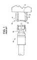
- FIG. 1One example of a known seal ring is illustrated in FIG. 1 .
- a seal ring 10typically has a smooth outer surface 12 and a first internal bore 14 that is slightly smaller than the diameter of the threaded section 16 of terminal 18 .
- Terminal 18projects out from a wall surface, for example the exterior surface of an electrical or electronic device.
- This seal ring 10also has a second internal bore 20 that has a diameter slightly smaller than the coupling nut 22 associated with coaxial cable connector 24 . In this manner, a tight seal may be achieved by the tight fit between the seal ring 10 and, at each end, the coupling nut 22 and the threaded section 16 of terminal 18 .
- a flippable seal memberfor use with a coaxial cable connector and a terminal to seal an interface between the coaxial cable connector and the terminal
- the flippable seal memberincludes a seal body comprising a first section having a first outer surface and a second section having a second outer surface, wherein the first section is capable of being flipped toward the second section such that at least a portion of the first outer surface contacts the second outer surface.
- the flippable seal membercan be deployed as a flip-up seal member or a flip-down seal member.
- the seal memberhas a first resting state and a second resting state, and in the second resting state, at least a portion of the first outer surface is perpendicular to at least a portion of the second outer surface.
- the seal bodyhas a hinge portion disposed between the first and second sections and in other embodiments the seal body has a flexure region.
- a flippable seal member seal memberfor use with a coaxial cable connector and a terminal to seal an interface between the coaxial cable connector and the terminal, the flippable seal member including a seal body comprising a first section having a first outer surface and a second section having a second outer surface, wherein, in a first resting state, the first outer surface and the second outer surfaces face radially outwardly; and wherein, in a second resting state, at least a portion of the first outer surface contacts the second outer surface.
- FIG. 1illustrates in partial cross section a prior art seal installed on a terminal with a coaxial cable connector positioned to be connected to the terminal;
- FIG. 2is a cutaway view of the flippable seal member of one embodiment of flippable seal member as disclosed herein in a first resting state;
- FIG. 3illustrates a cutaway view of one embodiment of flippable seal member of FIG. 2 prior to installation onto a coaxial cable connector and a terminal;
- FIG. 4is a cutaway view of the flippable seal member of FIG. 2 installed on a terminal;
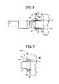
- FIG. 5is a cutaway view of the flippable seal member of FIG. 2 partially installed on a terminal in a second resting state;
- FIG. 6is a cutaway view of the flippable seal member of FIG. 2 fully installed on a terminal;
- FIG. 7is a partial side cutaway view of the flippable member of FIGS. 2-6 with the coaxial cable connector installed on the terminal;
- FIG. 8is a partial side cutaway view of the flippable member of FIGS. 2-7 fully installed to seal the interface of the coaxial cable connector and the terminal;
- FIG. 9is a cutaway view of the flippable seal member of FIG. 2 partially installed on an alternative terminal and in the second resting state;
- FIG. 10a cutaway view of another embodiment of flippable seal member as disclosed herein;
- FIG. 10Ais an alternative embodiment of the flippable seal member of FIG. 10 ;
- FIG. 11is an elevational view of the flippable seal member of FIG. 10 ;
- FIG. 12is a cutaway view of the flippable seal member of FIG. 10 installed on a coaxial cable connector, the seal member in a second resting state;
- FIG. 13is a partial side cutaway view of the flippable seal member of FIG. 10 with the coaxial cable connector installed on the terminal;
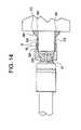
- FIG. 14is partial side cutaway view of the flippable seal member of FIG. 10 fully installed to seal the interface of the coaxial cable connector and the terminal;
- FIG. 15is an elevational view of a flippable seal member in another second resting position.
- the seal member 100comprises a generally tubular seal body 102 that has a first section 104 and a second section 106 .
- the seal body 102has an internal surface 108 defining an opening 110 between a first end 112 and a second end 114 .
- generally tubularwe mean that the internal surface 108 and/or the external surface of the seal body can have one or a plurality of diameters and/or cross-sectional shapes.
- Opening 110preferably has an enlarged portion 116 adjacent first end 112 , the enlarged portion 116 of opening 110 also preferably includes a forward facing annular face 118 .
- the seal body 102Adjacent second end 114 , the seal body 102 preferably has a rearward facing internal chamfered portion 120 to assist with inserting a connector.
- the first section 104 of seal body 102has a first outer surface 122 and the second section 106 of seal body 102 has a second outer surface 124 .
- the end 112has a diameter and tubular wall thickness that is larger than the diameter and thickness at the second end 114 .
- the first end 112has a first axial end surface 126 and second end 114 has a second axial end surface 128 .
- Disposed between the first section 104 and the second section 106is a hinge portion 130 .
- the hinge portion 130preferably has a reduced tubular wall thickness preferably with an outer diameter that is smaller than the outer diameter of the seal body 102 at both the first and second ends 112 , 114 .
- the seal member 100is illustrated in FIG. 2 as being in a first resting state. That is, the seal member 100 will remain as illustrated in FIG. 2 unless it is acted upon by some outside force, i.e., a user or an installer.
- first section 104 and the second section 106are generally parallel to one another, as are the first and second axial end surfaces 126 , 128 .
- the first and second outer surfaces 122 , 124face radially outward.
- the seal member 100is preferably molded from a rubber-like material such as EPDM, vinyl, or a like material. It is also preferably treated to resist the deleterious effects of ultraviolet light so that it maintains resiliency after being outside for extended periods of time.
- the opening 110 at second end 114is preferably slightly smaller than the terminal 18 on which it is to be installed. As illustrated in FIG. 3 , the second end 114 will engage the terminal 18 , while first end 112 will engage the coaxial cable connector 24 and, in particular, the coupler such as coupling nut 22 . Similarly, the diameter of the enlarged portion 116 of opening 110 adjacent first end 112 is preferably smaller than an outermost diameter of the coupling nut 22 .
- seal member 100As noted above, second end 114 is aligned with the threaded section 16 of terminal 18 .
- the rearward facing internal chamfer portion 120assists in directing the threaded section 16 of terminal 18 into the opening 110 of seal body 102 .
- the seal member 100As the opening 110 is slightly smaller in diameter at the second end 114 than the diameter of the threaded section 16 , the seal member 100 is stretched slightly to accommodate the larger diameter of the threaded section 16 and to sealingly engage the seal member 100 to the terminal 18 .
- the enlarged diameter of the body member 102 at first end 112which provides for an increased thickness at the first section 104 , and the first axial end surface 126 also provides an adequate surface area for leverage for the user to grip and to install the seal member 100 on the terminal 18 .
- the usercan, as illustrated in FIG. 5 , flip the first end 112 about hinge portion 126 towards the second end 114 , i.e. the seal member 100 is flipped up from a first resting state to a second resting state.
- the seal member 100In this second resting state, at least a portion of the first outer surface 122 of the first section 104 touches the second outer surface 124 of the second section 106 .
- seal member 100will remain in the second resting state until again acted upon by an outside force, e.g., a user or an installer, i.e. until flipped down.
- an outside forcee.g., a user or an installer
- the internal surface 108is exposed in the second resting state but does not touch the first or second outer surfaces 122 , 124 .
- the first axial end surface 126is now directed radially outward.
- the exposed internal surface 108 as well as the enlarged portion 116provide a surface against which a user may push the seal member 100 further along terminal 18 as illustrated in FIG. 6 thereby increasing the torque available to twist and/or slide the seal member 100 onto the terminal.
- the seal member 100sealingly engages the terminal 18 as well as the threaded section 16 .
- a portion of the threaded section 16is visible and available to the coaxial cable connector 24 .
- the coaxial cable connector 24may be easily threaded onto the threaded section 16 without interference or contact from the seal member 100 .
- the usermay flip the first section 104 back from the second resting state to the first resting state as illustrated in FIG. 8 .
- the outer surface of the second sectionis exposed, i.e. not covered by the first section, so as to provide sufficient space A between the exterior surface or wall of a device or other object from which the terminal 18 extends and the first end 112 to allow a user to insert a tool or fingers to flip the first section 104 back to the first resting state.
- the first section 104engages the coupling nut 22 of the coaxial cable connector 24 . More specifically, the enlarged portion 116 of the opening 110 engages the coupling nut 22 . It should be noted, however, that seal member 100 need not have a large portion 116 of opening 110 adjacent the first end 112 of seal body 102 . Since a seal member 100 is preferably molded from a rubber-like material, seal member 100 preferably generally conforms to the configuration of the coaxial cable connector 24 , and more particularly, the coupling nut 22 .
- seal member 100may conform to a terminal 18 ′ that has an enlarged portion 16 ′ adjacent the threaded portion 16 . Since seal member 100 is deformable, the second section 106 will accommodate the enlarged portion 16 ′.
- Seal member 200comprises a seal body 202 and has a first section 204 and a second section 206 .
- the seal body 202has an internal surface 208 defining an opening 210 between a first end 212 and a second end 214 .
- Opening 210preferably has an enlarged tubular wall thickness portion 216 adjacent the second end 214 , the enlarged portion 216 of opening 210 also preferably includes a forward facing annular face 218 .
- Adjacent first end 212 , the seal body 202preferably has a rearward facing internal chamfer portion 220 to assist with inserting a connector.
- the first section 204 of seal body 202has a first outer surface 222 and the second section 206 of seal body 202 has second outer surface 224 .
- the first end 212has an outer diameter and a tubular wall thickness that are larger than at the second end 214 .
- the first end 212has a first axial end surface 226 and second end 214 has a second axial end surface 228 .
- Disposed between the first section 204 and the second section 206is a hinge portion 230 .
- the hinge portion 230preferably has a reduced outer diameter, an outer diameter that is smaller than the outer diameter of the seal body 202 at both the first and second ends 214 , 216 .
- seal member 200is illustrated in FIG. 10 as being in a first resting state. That is, the seal member 200 will remain as illustrated in FIG. 10 unless it is acted upon by some outside force, i.e., a user or an installer.
- first section 204 in the second section 206are generally parallel to one another, as are the first and second axial end surfaces 226 , 228 .
- the first and second outer surfaces 222 , 224face radially outward.
- the seal member 200is preferably molded from a rubber-like material such as EPDM, vinyl, or a like material. It is also preferably treated to resist the deleterious effects of ultraviolet light so that it maintains resiliency after being outside for extended periods of time.
- FIG. 10AAnother embodiment of a seal member 200 ′ is illustrated in FIG. 10A .
- Seal member 200 ′is similar to seal member 200 , but has the hinge portion 230 ′ in the internal surface 208 ′ of seal member 200 ′.
- Hinge portion 230 ′is illustrated as being a sharp groove, but it could also be more rounded and smooth.
- the seal member 200 ′preferably has a reduced tubular wall thickness at hinge portion 230 ′.
- An internal hinge portionlike hinge portion 230 ′, may also be used in seal member 100 , rather than the hinge portion 130 as discussed above.
- Seal member 200 ′also preferably includes indicia, a reflective surface, and/or contrasting colors to allow an installer to quickly, as well as from a distance, determine the position or resting state of the seal members.
- seal member 200 ′(or any of the other embodiments disclosed herein) may have the indicia 232 ′ on the axial end surfaces, which is illustrated in FIG. 10A as a reflective coating or a different seal body color that is highly visible relative to the remainder of the seal member 200 ′.
- the indicia 232 ′may also be on internal surface 208 ′, particularly at the first section 204 ′, although it may cover any portion of the internal surface 208 ′, including the entirety of the internal surface 208 ′.
- the axial end surface (e.g., 226 ′) and a portion of the internal surface (e.g., 208 ′)will face radially outward (see, e.g., FIGS. 9 and 12 ) allowing the installer to view the indicia 232 ′, particularly if a strong light is shone on it.
- the indicia 232 ′is not readily visible due to contact of the seal member with the terminal or the connector (see, e.g., FIGS. 8 & 14 ).
- the indicia 232 ′although illustrated in FIG.
- the first sectionhas a first inner surface, wherein the first inner surface is visually distinguishable from the first outer surface by a visually detectable difference in color, shading, coating, or finish between the first inner surface and the first outer surface.
- the first sectionhas a first end surface, wherein the first end surface is visually distinguishable from one or both of the first outer surface and the first inner surface by a detectable difference in color, shading, coating, or finish.
- the first sectionfurther comprises a first inner surface and a first end surface
- the second sectionfurther comprises a second inner surface and a second end surface
- the first inner surfaceis visually distinguishable from at least one of the group consisting of the first outer surface, the first end surface, the second outer surface, the second inner surface, and the second end surface, by a detectable difference in color, shading, coating, or finish.
- either the first end surfaceis visually distinguishable from other surfaces such as the first outer surface or the first inner surface or the or the second outer surface or the second inner surface or the second end surface by a detectable difference in color, shading, coating, or finish.
- Seal member 200has an opening 210 is preferably slightly smaller than the coaxial cable connector 24 on which is to be installed. As illustrated in FIGS. 11 and 12 , the seal member 200 is preferably installed on the coupling nut 22 of the coaxial cable connector 24 rather than on the threaded section 16 of terminal 18 . Similarly, the second end 214 of the seal number 200 is disposed over the coupling nut 22 . The enlarged portion 216 of opening 210 adjacent the second end 214 , which is slightly smaller in diameter than the coupling nut 22 , snugly engages coupling nut 22 to prevent moisture from entering therebetween. After seal member 200 is pushed on to coaxial cable connector 24 , the first end 212 is flipped about hinge portion 230 towards the second end 214 .
- the larger diameter and thickness of the first outer surface 222allows the flipping of the first end 212 towards the second end 214 with relative ease.
- the seal member 200is illustrated in the FIGS. 11 and 12 in the second resting state. In the second resting state, at least a portion of the first outer surface 222 is in contact with a portion of second outer surface 224 . It is also true that the second outer surface 224 is pointing radially outward while at least a portion of the first outer surface 222 is pointing radially inward. Also in this position, at least a portion of internal surface 208 is directed radially outward and presents an increased diameter grasping surface for a user thereby allowing greater ease of applying torque for twisting seal member 200 or ease of sliding the seal member 200 .
- the combination of the coaxial cable connector 24 in the seal member 200are then installed on the threaded portion 16 of terminal 18 as illustrated in FIG. 13 . Because the internal surface 208 presents an enhanced grasping surface for the user, the user can simply rotate the coupling nut 22 along with the seal member 200 until the coaxial cable connector 24 is fully installed on the terminal 18 .
- the usercan then, as illustrated by the arrows in FIG. 13 , flip the first end 212 back about the hinge portion 226 to cover and engage the exposed threaded portion 16 of terminal 18 .
- the first end 212engages terminal 18 and a portion of internal surface 208 engages the threaded portion 16 to keep the moisture from entering therein.
- the first end 212does not need to be flipped back as far as illustrated in FIGS. 11 and 12 , but might only need to be flipped back partially, as illustrated in FIG. 15 .
- the flippable seal membercan provide terminal/connector junction sealing and can be easily installed, and can be made to cover a range of terminal port lengths; the seal member can allow easier turning of the connector coupler during installation yet can provide resistance to coupler rotation after the installation is complete.
Landscapes
- Connector Housings Or Holding Contact Members (AREA)
Abstract
Description
Claims (33)
Priority Applications (3)
| Application Number | Priority Date | Filing Date | Title |
|---|---|---|---|
| US11/607,759US7311555B1 (en) | 2006-12-01 | 2006-12-01 | Flippable seal member coaxial cable connector and terminal |
| PCT/US2007/024592WO2008069952A2 (en) | 2006-12-01 | 2007-11-29 | Seal member for coaxial cable connector and terminal |
| TW096145831ATWI360929B (en) | 2006-12-01 | 2007-11-30 | Seal member for coaxial cable connector and termin |
Applications Claiming Priority (1)
| Application Number | Priority Date | Filing Date | Title |
|---|---|---|---|
| US11/607,759US7311555B1 (en) | 2006-12-01 | 2006-12-01 | Flippable seal member coaxial cable connector and terminal |
Publications (1)
| Publication Number | Publication Date |
|---|---|
| US7311555B1true US7311555B1 (en) | 2007-12-25 |
Family
ID=38863232
Family Applications (1)
| Application Number | Title | Priority Date | Filing Date |
|---|---|---|---|
| US11/607,759ActiveUS7311555B1 (en) | 2006-12-01 | 2006-12-01 | Flippable seal member coaxial cable connector and terminal |
Country Status (3)
| Country | Link |
|---|---|
| US (1) | US7311555B1 (en) |
| TW (1) | TWI360929B (en) |
| WO (1) | WO2008069952A2 (en) |
Cited By (39)
| Publication number | Priority date | Publication date | Assignee | Title |
|---|---|---|---|---|
| US20080311789A1 (en)* | 2007-06-15 | 2008-12-18 | Donald Andrew Burris | Seals and methods for sealing coaxial cable connectors and terminals |
| WO2008157783A1 (en)* | 2007-06-20 | 2008-12-24 | Amphenol Corporation | Connector assembly with gripping sleeve |
| US7544094B1 (en) | 2007-12-20 | 2009-06-09 | Amphenol Corporation | Connector assembly with gripping sleeve |
| US20090291580A1 (en)* | 2008-05-20 | 2009-11-26 | Donald Andrew Burris | Seal member for coaxial cable connector and terminal |
| US20100022120A1 (en)* | 2008-07-27 | 2010-01-28 | Bradley Edward Joseph | Coaxial cable connector nut rotation aid |
| US20100233902A1 (en)* | 2009-03-13 | 2010-09-16 | Youtsey Timothy L | Jumper sleeve for connecting and disconnecting male f connector to and from female f connector |
| US20120196464A1 (en)* | 2011-01-31 | 2012-08-02 | Yueh Chiung Lu | Water seal connector |
| US20120244744A1 (en)* | 2011-03-21 | 2012-09-27 | Ching-Kun Huang | Structure of connector |
| US8480428B1 (en)* | 2012-01-09 | 2013-07-09 | Devin Sper | Waterproof BNC connector |
| US8579658B2 (en) | 2010-08-20 | 2013-11-12 | Timothy L. Youtsey | Coaxial cable connectors with washers for preventing separation of mated connectors |
| USD695695S1 (en) | 2012-10-25 | 2013-12-17 | Perfectvision Manufacturing, Inc. | Sealing connector boot with mandrel grip |
| WO2014135156A1 (en)* | 2013-03-07 | 2014-09-12 | Harting Electric Gmbh & Co. Kg | Surface-optimised plug connector |
| US8882520B2 (en) | 2010-05-21 | 2014-11-11 | Pct International, Inc. | Connector with a locking mechanism and a movable collet |
| US9028276B2 (en) | 2011-12-06 | 2015-05-12 | Pct International, Inc. | Coaxial cable continuity device |
| US9240636B2 (en) | 2011-05-19 | 2016-01-19 | Pct International, Inc. | Coaxial cable connector having a coupling nut and a conductive insert with a flange |
| US9407016B2 (en) | 2012-02-22 | 2016-08-02 | Corning Optical Communications Rf Llc | Coaxial cable connector with integral continuity contacting portion |
| US9484645B2 (en) | 2012-01-05 | 2016-11-01 | Corning Optical Communications Rf Llc | Quick mount connector for a coaxial cable |
| US9525220B1 (en) | 2015-11-25 | 2016-12-20 | Corning Optical Communications LLC | Coaxial cable connector |
| US9548557B2 (en) | 2013-06-26 | 2017-01-17 | Corning Optical Communications LLC | Connector assemblies and methods of manufacture |
| US9548572B2 (en) | 2014-11-03 | 2017-01-17 | Corning Optical Communications LLC | Coaxial cable connector having a coupler and a post with a contacting portion and a shoulder |
| US9590287B2 (en) | 2015-02-20 | 2017-03-07 | Corning Optical Communications Rf Llc | Surge protected coaxial termination |
| US9722363B2 (en) | 2012-10-16 | 2017-08-01 | Corning Optical Communications Rf Llc | Coaxial cable connector with integral RFI protection |
| US9762008B2 (en) | 2013-05-20 | 2017-09-12 | Corning Optical Communications Rf Llc | Coaxial cable connector with integral RFI protection |
| US9837777B1 (en) | 2016-08-30 | 2017-12-05 | Steren Electronics International, Llc | Expandable cable connector torque adapter |
| US9859631B2 (en) | 2011-09-15 | 2018-01-02 | Corning Optical Communications Rf Llc | Coaxial cable connector with integral radio frequency interference and grounding shield |
| US9905959B2 (en) | 2010-04-13 | 2018-02-27 | Corning Optical Communication RF LLC | Coaxial connector with inhibited ingress and improved grounding |
| US9929498B2 (en) | 2016-09-01 | 2018-03-27 | Times Fiber Communications, Inc. | Connector assembly with torque sleeve |
| US9929499B2 (en) | 2016-09-01 | 2018-03-27 | Amphenol Corporation | Connector assembly with torque sleeve |
| USD815046S1 (en) | 2016-08-30 | 2018-04-10 | Steren Electronics International, Llc | Sleeve for cable connector |
| US10033122B2 (en) | 2015-02-20 | 2018-07-24 | Corning Optical Communications Rf Llc | Cable or conduit connector with jacket retention feature |
| US10211547B2 (en) | 2015-09-03 | 2019-02-19 | Corning Optical Communications Rf Llc | Coaxial cable connector |
| US10290958B2 (en) | 2013-04-29 | 2019-05-14 | Corning Optical Communications Rf Llc | Coaxial cable connector with integral RFI protection and biasing ring |
| US10439302B2 (en) | 2017-06-08 | 2019-10-08 | Pct International, Inc. | Connecting device for connecting and grounding coaxial cable connectors |
| CN110534937A (en)* | 2019-09-27 | 2019-12-03 | 广州番禺电缆集团有限公司 | A kind of water proof type connecting terminal |
| US10756455B2 (en) | 2005-01-25 | 2020-08-25 | Corning Optical Communications Rf Llc | Electrical connector with grounding member |
| WO2021022260A1 (en)* | 2019-08-01 | 2021-02-04 | Ppc Broadband, Inc. | Coupler seal for coaxial cable system components |
| JP2021026969A (en)* | 2019-08-08 | 2021-02-22 | 株式会社日本ビデオシステム | Coaxial connector |
| WO2024096860A1 (en)* | 2022-10-31 | 2024-05-10 | ADB SAFEGATE Americas, LLC | Electrical connector |
| US12034264B2 (en) | 2021-03-31 | 2024-07-09 | Corning Optical Communications Rf Llc | Coaxial cable connector assemblies with outer conductor engagement features and methods for using the same |
Families Citing this family (1)
| Publication number | Priority date | Publication date | Assignee | Title |
|---|---|---|---|---|
| CN103326174A (en)* | 2013-06-25 | 2013-09-25 | 苏州华旃航天电器有限公司 | Waterproof cable clamp of connector |
Citations (9)
| Publication number | Priority date | Publication date | Assignee | Title |
|---|---|---|---|---|
| US4410162A (en)* | 1980-08-16 | 1983-10-18 | Dyckerhoff & Widmann Aktiengesellschaft | Recoverable form part for use in the region where a tendon is anchored in a prestressed concrete component |
| US5342218A (en)* | 1991-03-22 | 1994-08-30 | Raychem Corporation | Coaxial cable connector with mandrel spacer and method of preparing coaxial cable |
| US5467848A (en)* | 1993-08-18 | 1995-11-21 | Aeromatics Automotive, Inc. | Slider assembly for automotive brake caliper |
| US20020009922A1 (en)* | 1999-03-09 | 2002-01-24 | Sumitomo Wiring Systems, Ltd. | Waterproof connector with sealing member |
| US6787701B2 (en) | 2000-10-06 | 2004-09-07 | Tyco Electronics, Amp, K.K. | Waterproof grommet |
| US7097500B2 (en)* | 2004-06-25 | 2006-08-29 | John Mezzalingua Associates, Inc. | Nut seal assembly for coaxial cable system components |
| US7118416B2 (en)* | 2004-02-18 | 2006-10-10 | John Mezzalingua Associates, Inc. | Cable connector with elastomeric band |
| US7179100B2 (en)* | 2005-05-06 | 2007-02-20 | John Mezzalingua Associates Inc. | Security shield integral with tap faceplate |
| US7186127B2 (en)* | 2004-06-25 | 2007-03-06 | John Mezzalingua Associates, Inc. | Nut seal assembly for coaxial connector |
Family Cites Families (7)
| Publication number | Priority date | Publication date | Assignee | Title |
|---|---|---|---|---|
| DE7149556U (en)* | Rheinstahl Huettenwerke Ag | Socket pipe seal | ||
| DE924300C (en)* | 1952-02-07 | 1955-02-28 | Franz Clouth Rheinische Gummiw | Rubber roll seal |
| CH376732A (en)* | 1959-11-21 | 1964-04-15 | Muenster Fa | Detachable pipe coupling with airtight seal, especially for vacuum cleaners |
| FR1595762A (en)* | 1968-11-26 | 1970-06-15 | ||
| US4717355A (en)* | 1986-10-24 | 1988-01-05 | Raychem Corp. | Coaxial connector moisture seal |
| US5605468A (en)* | 1995-11-22 | 1997-02-25 | Tescorp Seismic Products, Inc. | Electrical connector assembly having replaceable sleeve seal |
| US5866849A (en)* | 1996-08-08 | 1999-02-02 | Antec Corporation | Connector sealing sleeve |
- 2006
- 2006-12-01USUS11/607,759patent/US7311555B1/enactiveActive
- 2007
- 2007-11-29WOPCT/US2007/024592patent/WO2008069952A2/enactiveApplication Filing
- 2007-11-30TWTW096145831Apatent/TWI360929B/ennot_activeIP Right Cessation
Patent Citations (10)
| Publication number | Priority date | Publication date | Assignee | Title |
|---|---|---|---|---|
| US4410162A (en)* | 1980-08-16 | 1983-10-18 | Dyckerhoff & Widmann Aktiengesellschaft | Recoverable form part for use in the region where a tendon is anchored in a prestressed concrete component |
| US5342218A (en)* | 1991-03-22 | 1994-08-30 | Raychem Corporation | Coaxial cable connector with mandrel spacer and method of preparing coaxial cable |
| US5467848A (en)* | 1993-08-18 | 1995-11-21 | Aeromatics Automotive, Inc. | Slider assembly for automotive brake caliper |
| US20020009922A1 (en)* | 1999-03-09 | 2002-01-24 | Sumitomo Wiring Systems, Ltd. | Waterproof connector with sealing member |
| US6787701B2 (en) | 2000-10-06 | 2004-09-07 | Tyco Electronics, Amp, K.K. | Waterproof grommet |
| US7118416B2 (en)* | 2004-02-18 | 2006-10-10 | John Mezzalingua Associates, Inc. | Cable connector with elastomeric band |
| US7097500B2 (en)* | 2004-06-25 | 2006-08-29 | John Mezzalingua Associates, Inc. | Nut seal assembly for coaxial cable system components |
| US7186127B2 (en)* | 2004-06-25 | 2007-03-06 | John Mezzalingua Associates, Inc. | Nut seal assembly for coaxial connector |
| US20070134967A1 (en)* | 2004-06-25 | 2007-06-14 | John Mezzalingua Associates, Inc. | Nut seal assembly for coaxial connector |
| US7179100B2 (en)* | 2005-05-06 | 2007-02-20 | John Mezzalingua Associates Inc. | Security shield integral with tap faceplate |
Cited By (63)
| Publication number | Priority date | Publication date | Assignee | Title |
|---|---|---|---|---|
| US10756455B2 (en) | 2005-01-25 | 2020-08-25 | Corning Optical Communications Rf Llc | Electrical connector with grounding member |
| US7938662B2 (en) | 2007-06-15 | 2011-05-10 | Corning Gilbert Inc. | Seals and methods for sealing coaxial cable connectors and terminals |
| WO2008156564A1 (en)* | 2007-06-15 | 2008-12-24 | Corning Gilbert Inc. | Seals and methods for sealing coaxial cable connectors and terminals |
| US20080311789A1 (en)* | 2007-06-15 | 2008-12-18 | Donald Andrew Burris | Seals and methods for sealing coaxial cable connectors and terminals |
| WO2008157783A1 (en)* | 2007-06-20 | 2008-12-24 | Amphenol Corporation | Connector assembly with gripping sleeve |
| US20080318469A1 (en)* | 2007-06-20 | 2008-12-25 | Amphenol Corporation | Connector assembly with gripping sleeve |
| US7618276B2 (en) | 2007-06-20 | 2009-11-17 | Amphenol Corporation | Connector assembly with gripping sleeve |
| US7544094B1 (en) | 2007-12-20 | 2009-06-09 | Amphenol Corporation | Connector assembly with gripping sleeve |
| US20090163076A1 (en)* | 2007-12-20 | 2009-06-25 | Amphenol Corporation | Connector assembly with gripping sleeve |
| US20090291580A1 (en)* | 2008-05-20 | 2009-11-26 | Donald Andrew Burris | Seal member for coaxial cable connector and terminal |
| US20100022120A1 (en)* | 2008-07-27 | 2010-01-28 | Bradley Edward Joseph | Coaxial cable connector nut rotation aid |
| US7946199B2 (en) | 2008-07-27 | 2011-05-24 | The Jumper Shop, Llc | Coaxial cable connector nut rotation aid |
| US7837501B2 (en)* | 2009-03-13 | 2010-11-23 | Phoenix Communications Technologies International | Jumper sleeve for connecting and disconnecting male F connector to and from female F connector |
| US20100233902A1 (en)* | 2009-03-13 | 2010-09-16 | Youtsey Timothy L | Jumper sleeve for connecting and disconnecting male f connector to and from female f connector |
| US9905959B2 (en) | 2010-04-13 | 2018-02-27 | Corning Optical Communication RF LLC | Coaxial connector with inhibited ingress and improved grounding |
| US10312629B2 (en) | 2010-04-13 | 2019-06-04 | Corning Optical Communications Rf Llc | Coaxial connector with inhibited ingress and improved grounding |
| US8882520B2 (en) | 2010-05-21 | 2014-11-11 | Pct International, Inc. | Connector with a locking mechanism and a movable collet |
| US8579658B2 (en) | 2010-08-20 | 2013-11-12 | Timothy L. Youtsey | Coaxial cable connectors with washers for preventing separation of mated connectors |
| US20120196464A1 (en)* | 2011-01-31 | 2012-08-02 | Yueh Chiung Lu | Water seal connector |
| US20120244744A1 (en)* | 2011-03-21 | 2012-09-27 | Ching-Kun Huang | Structure of connector |
| US9240636B2 (en) | 2011-05-19 | 2016-01-19 | Pct International, Inc. | Coaxial cable connector having a coupling nut and a conductive insert with a flange |
| US9859631B2 (en) | 2011-09-15 | 2018-01-02 | Corning Optical Communications Rf Llc | Coaxial cable connector with integral radio frequency interference and grounding shield |
| US9028276B2 (en) | 2011-12-06 | 2015-05-12 | Pct International, Inc. | Coaxial cable continuity device |
| US9577391B2 (en) | 2011-12-06 | 2017-02-21 | Pct International, Inc. | Coaxial cable continuity device |
| US9768566B2 (en) | 2011-12-06 | 2017-09-19 | Pct International, Inc. | Coaxial cable continuity device |
| US9484645B2 (en) | 2012-01-05 | 2016-11-01 | Corning Optical Communications Rf Llc | Quick mount connector for a coaxial cable |
| US9768565B2 (en) | 2012-01-05 | 2017-09-19 | Corning Optical Communications Rf Llc | Quick mount connector for a coaxial cable |
| US8480428B1 (en)* | 2012-01-09 | 2013-07-09 | Devin Sper | Waterproof BNC connector |
| US9407016B2 (en) | 2012-02-22 | 2016-08-02 | Corning Optical Communications Rf Llc | Coaxial cable connector with integral continuity contacting portion |
| US10236636B2 (en) | 2012-10-16 | 2019-03-19 | Corning Optical Communications Rf Llc | Coaxial cable connector with integral RFI protection |
| US9912105B2 (en) | 2012-10-16 | 2018-03-06 | Corning Optical Communications Rf Llc | Coaxial cable connector with integral RFI protection |
| US9722363B2 (en) | 2012-10-16 | 2017-08-01 | Corning Optical Communications Rf Llc | Coaxial cable connector with integral RFI protection |
| USD695695S1 (en) | 2012-10-25 | 2013-12-17 | Perfectvision Manufacturing, Inc. | Sealing connector boot with mandrel grip |
| RU2616184C2 (en)* | 2013-03-07 | 2017-04-13 | Хартинг Электрик Гмбх Унд Ко. Кг | Surface optimized plug connector |
| WO2014135156A1 (en)* | 2013-03-07 | 2014-09-12 | Harting Electric Gmbh & Co. Kg | Surface-optimised plug connector |
| US9543701B2 (en) | 2013-03-07 | 2017-01-10 | Harting Electric Gmbh & Co. Kg | Surface-optimised plug-in connector |
| JP2016509355A (en)* | 2013-03-07 | 2016-03-24 | ハルティング エレクトリック ゲゼルシャフト ミット ベシュレンクテル ハフツング ウント コンパニー コマンディートゲゼルシャフトHARTING Electric GmbH & Co. KG | Surface-optimized connector |
| US10290958B2 (en) | 2013-04-29 | 2019-05-14 | Corning Optical Communications Rf Llc | Coaxial cable connector with integral RFI protection and biasing ring |
| US10396508B2 (en) | 2013-05-20 | 2019-08-27 | Corning Optical Communications Rf Llc | Coaxial cable connector with integral RFI protection |
| US9762008B2 (en) | 2013-05-20 | 2017-09-12 | Corning Optical Communications Rf Llc | Coaxial cable connector with integral RFI protection |
| US9548557B2 (en) | 2013-06-26 | 2017-01-17 | Corning Optical Communications LLC | Connector assemblies and methods of manufacture |
| US9548572B2 (en) | 2014-11-03 | 2017-01-17 | Corning Optical Communications LLC | Coaxial cable connector having a coupler and a post with a contacting portion and a shoulder |
| US9991651B2 (en) | 2014-11-03 | 2018-06-05 | Corning Optical Communications Rf Llc | Coaxial cable connector with post including radially expanding tabs |
| US10033122B2 (en) | 2015-02-20 | 2018-07-24 | Corning Optical Communications Rf Llc | Cable or conduit connector with jacket retention feature |
| US9590287B2 (en) | 2015-02-20 | 2017-03-07 | Corning Optical Communications Rf Llc | Surge protected coaxial termination |
| US10211547B2 (en) | 2015-09-03 | 2019-02-19 | Corning Optical Communications Rf Llc | Coaxial cable connector |
| US9525220B1 (en) | 2015-11-25 | 2016-12-20 | Corning Optical Communications LLC | Coaxial cable connector |
| US9882320B2 (en) | 2015-11-25 | 2018-01-30 | Corning Optical Communications Rf Llc | Coaxial cable connector |
| US10938174B2 (en) | 2016-08-30 | 2021-03-02 | Steren Electronics International, Llc | Expandable cable connector torque adapter |
| US9837777B1 (en) | 2016-08-30 | 2017-12-05 | Steren Electronics International, Llc | Expandable cable connector torque adapter |
| USD815046S1 (en) | 2016-08-30 | 2018-04-10 | Steren Electronics International, Llc | Sleeve for cable connector |
| US9929498B2 (en) | 2016-09-01 | 2018-03-27 | Times Fiber Communications, Inc. | Connector assembly with torque sleeve |
| US9929499B2 (en) | 2016-09-01 | 2018-03-27 | Amphenol Corporation | Connector assembly with torque sleeve |
| US10270206B2 (en) | 2016-09-01 | 2019-04-23 | Amphenol Corporation | Connector assembly with torque sleeve |
| US9991630B1 (en) | 2016-09-01 | 2018-06-05 | Amphenol Corporation | Connector assembly with torque sleeve |
| US10439302B2 (en) | 2017-06-08 | 2019-10-08 | Pct International, Inc. | Connecting device for connecting and grounding coaxial cable connectors |
| US10855003B2 (en) | 2017-06-08 | 2020-12-01 | Pct International, Inc. | Connecting device for connecting and grounding coaxial cable connectors |
| WO2021022260A1 (en)* | 2019-08-01 | 2021-02-04 | Ppc Broadband, Inc. | Coupler seal for coaxial cable system components |
| US11742611B2 (en) | 2019-08-01 | 2023-08-29 | Ppc Broadband, Inc. | Coupler seal for coaxial cable system components |
| JP2021026969A (en)* | 2019-08-08 | 2021-02-22 | 株式会社日本ビデオシステム | Coaxial connector |
| CN110534937A (en)* | 2019-09-27 | 2019-12-03 | 广州番禺电缆集团有限公司 | A kind of water proof type connecting terminal |
| US12034264B2 (en) | 2021-03-31 | 2024-07-09 | Corning Optical Communications Rf Llc | Coaxial cable connector assemblies with outer conductor engagement features and methods for using the same |
| WO2024096860A1 (en)* | 2022-10-31 | 2024-05-10 | ADB SAFEGATE Americas, LLC | Electrical connector |
Also Published As
| Publication number | Publication date |
|---|---|
| WO2008069952A2 (en) | 2008-06-12 |
| TWI360929B (en) | 2012-03-21 |
| TW200845508A (en) | 2008-11-16 |
| WO2008069952A3 (en) | 2008-11-06 |
Similar Documents
| Publication | Publication Date | Title |
|---|---|---|
| US7311555B1 (en) | Flippable seal member coaxial cable connector and terminal | |
| CN101836335B (en) | Seals and methods for sealing coaxial cable connectors and terminals | |
| US9106003B2 (en) | Cover for cable connectors | |
| US7118416B2 (en) | Cable connector with elastomeric band | |
| KR101044272B1 (en) | Nut Seal Assembly for Coaxial Connectors | |
| US7014501B2 (en) | Environmentally protected and tamper resistant CATV drop connector and method | |
| US10847925B2 (en) | Cable connector cover | |
| US20080139028A1 (en) | Compression seal for coaxial cable connector and terminal | |
| RU2198455C2 (en) | Insertion box for hose-type cables such as those used for mines | |
| US20080171466A1 (en) | Cable connector with bushing that permits visual verification | |
| US20070042642A1 (en) | Coaxial cable compression connector | |
| EP0618655A1 (en) | Cable gland | |
| US20080299818A1 (en) | Jacket sleeve with grippable tabs for a cable connector | |
| US20090291580A1 (en) | Seal member for coaxial cable connector and terminal | |
| KR200401178Y1 (en) | Sleeve for water-proof and insulating | |
| EP0694225B1 (en) | Cable sealing and locking device | |
| EP3427358B1 (en) | Cable gland device for the electric interconnection of electric cables | |
| WO1996020516A1 (en) | Coaxial cable connector | |
| JP2004158427A (en) | Waterproof connector | |
| AU725764B2 (en) | Coaxial cable connector for CATV systems | |
| AU3009200A (en) | Electrical connector assembly |
Legal Events
| Date | Code | Title | Description |
|---|---|---|---|
| AS | Assignment | Owner name:CORNING GILBERT, INC., NEW YORK Free format text:ASSIGNMENT OF ASSIGNORS INTEREST;ASSIGNORS:BURRIS, DONALD ANDREW;LUTZ, WILLIAM BERNARD;WOOD, KENNETH STEVEN;REEL/FRAME:020051/0266;SIGNING DATES FROM 20071022 TO 20071023 | |
| STCF | Information on status: patent grant | Free format text:PATENTED CASE | |
| FPAY | Fee payment | Year of fee payment:4 | |
| FPAY | Fee payment | Year of fee payment:8 | |
| AS | Assignment | Owner name:CORNING OPTICAL COMMUNICATIONS RF LLC, ARIZONA Free format text:CHANGE OF NAME;ASSIGNOR:CORNING GILBERT, INC.;REEL/FRAME:036687/0562 Effective date:20140122 | |
| MAFP | Maintenance fee payment | Free format text:PAYMENT OF MAINTENANCE FEE, 12TH YEAR, LARGE ENTITY (ORIGINAL EVENT CODE: M1553); ENTITY STATUS OF PATENT OWNER: LARGE ENTITY Year of fee payment:12 | |
| AS | Assignment | Owner name:CORNING OPTICAL COMMUNICATIONS RF LLC, ARIZONA Free format text:CORRECTIVE ASSIGNMENT TO CORRECT THE PROPERTY LISTED IN THE ORIGINAL COVER SHEET PREVIOUSLY RECORDED AT REEL: 036687 FRAME: 0562. ASSIGNOR(S) HEREBY CONFIRMS THE ASSIGNMENT;ASSIGNOR:CORNING GILBERT, INC.;REEL/FRAME:058300/0843 Effective date:20140122 | |
| AS | Assignment | Owner name:PPC BROADBAND, INC., NEW YORK Free format text:ASSIGNMENT OF ASSIGNORS INTEREST;ASSIGNOR:CORNING OPTICAL COMMUNICATIONS RF LLC;REEL/FRAME:058220/0154 Effective date:20210426 |