US7310443B1 - Automatic red eye detection and correction in digital images - Google Patents
Automatic red eye detection and correction in digital imagesDownload PDFInfo
- Publication number
- US7310443B1 US7310443B1US10/665,849US66584903AUS7310443B1US 7310443 B1US7310443 B1US 7310443B1US 66584903 AUS66584903 AUS 66584903AUS 7310443 B1US7310443 B1US 7310443B1
- Authority
- US
- United States
- Prior art keywords
- red
- color
- areas
- hard
- pixels
- Prior art date
- Legal status (The legal status is an assumption and is not a legal conclusion. Google has not performed a legal analysis and makes no representation as to the accuracy of the status listed.)
- Expired - Fee Related, expires
Links
Images


Classifications
- G—PHYSICS
- G06—COMPUTING OR CALCULATING; COUNTING
- G06V—IMAGE OR VIDEO RECOGNITION OR UNDERSTANDING
- G06V40/00—Recognition of biometric, human-related or animal-related patterns in image or video data
- G06V40/10—Human or animal bodies, e.g. vehicle occupants or pedestrians; Body parts, e.g. hands
- G06V40/18—Eye characteristics, e.g. of the iris
- G06V40/193—Preprocessing; Feature extraction
Definitions
- the present inventionrelates generally to digital image processing and editing, and more specifically, to methods for automatic detection and removal of red eye effect in digital images.
- red eyeTaking photographs of people and using flash often results in an artifact in the photograph commonly known as “red eye.”
- the artifactcan be present in an image taken from either a traditional film camera with flash, or a digital camera with flash.
- the artifactis generally manifested as an apparent red coloration of the iris of the eye, instead of the natural eye coloration, and is also referred to as “flash effect.”
- Red eyeis generally caused by the reflection of the intense light of a flash from the blood vessels of the retinas of a person's eyes.
- the degree of dilation of a subject's eyesvaries the apparent size of the red eye area. Because increased eye dilation results in a corresponding increase in red eye, it is common for attempts to reduce red eye to include measures to decrease eye dilation such as increasing ambient lighting, having a subject stare into a bright light just prior to taking a picture using flash, and so forth.
- FIG. 1Ais a diagram of an eye 10 illustrating a typical red eye effect as it might appear in a photographic image.
- Outer iris area 12may or may not be rendered with apparently normal coloration (e.g., blue, green, brown, etc.).
- Pupil area 14typically exhibits the redness that is known as red eye, and a small region 16 within pupil area 14 typically includes a bright white flash reflection.
- FIG. 1Bshows the eye 10 image of FIG. 1A with a typical digital image editing tool set of a computer program such as a photo editing application of a computer system implemented for red eye correction.
- Eye 10 imageincludes outer iris area 12 , pupil area 14 , and small region 16 within pupil area 14 having bright white flash reflection.
- a selection box 18may be defined around the general area of the red eye effect to be corrected.
- a user or operatorusually defines the selection box 18 around the area desired to be corrected.
- a computer user or operatormust identify an area or region in a digital image, which is stored as electrical signals in a computer system and displayed on a computer display output, and in some manner effect a selection or identification of the area for correction.
- a simple selection box 18is sufficient to identify the area. If the photo editing application includes some measure of semi-automatic correction, the defining of the selection box 18 may be all that is required of the user or operator prior to indicating an acceptance or rejection of the semi-automatic red eye correction within the selected or identified area. In some applications, a computer user or operator must scale the digital image to achieve as large an image as possible, or desired, and then must correct the color within the pupil region 14 of the eye 10 one pixel at a time until the desired color correction is effected.
- a pointer 20which may be in the shape of an arrow as illustrated, or in the shape of a paintbrush, a fountain pen, a sprayer, and so forth depending on the specific editing application, is used to select each pixel within the effected area, one at a time, and then each selected pixel is changed to a desired color.
- the pointer 20is typically used to define, size, and position the selection box 18 over the area to be corrected.
- the present inventionfills these needs by providing a method and system for automatically identifying and correcting red eye effect in digital images.
- the present inventioncan be implemented in numerous ways, including as a process, an apparatus, a system, a device, a method, or a computer readable media. Several embodiments of the present invention are described below.
- a method for performing red eye correction in an imageincludes providing a digital image, and identifying a red eye region in the digital image. A color correction is then applied to each pixel in the identified red eye region.
- the method for performing red eye correction in an imageis automatic and requires no input from a user to define the red eye region, or to apply the color correction.
- a method for performing red eye correction in a digital imageincludes identifying red areas in the digital image, and filtering out non-red eye red areas from the identified red areas.
- the filteringincludes the disregarding of areas too large for red eye effect, areas of an inappropriate shape to have red eye; areas of insufficient color intensity; areas of insufficient brightness dispersion, and areas failing to match a pre-determined spectral criteria.
- the methodfurther includes defining a region having red eye effect, and applying a color correction to the defined region. The method is performed automatically and without user input to define or to correct the region having red eye effect.
- computer readable mediahaving program instructions for removal of red eye effect in a digital image.
- the computer readable mediaincludes program instructions for automatically defining a region of the digital image having red eye effect, and for automatically applying a color correction to the defined region.
- User inputis not required to define the region of the digital image having red eye effect, and user input is not required to apply the color correction to the defined region.
- One notable benefit and advantage of the inventionis that the identification and correction of red eye is automatic. A user need not open an image editing program or function to produce quality images that have been corrected for red eye.
- FIG. 1Ais a diagram of an eye illustrating a typical red eye effect as it might appear in a digital image.
- FIG. 1Bshows the eye image of FIG. 1A with a typical digital image editing tool set implemented for red eye correction.
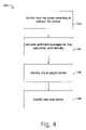
- FIG. 2is a high-level flowchart diagram illustrating method operations for automatic red eye removal in accordance with one embodiment of the present invention.
- FIG. 3Ashows the hue segments as defined, in accordance with one embodiment of the invention.
- FIG. 3Bis a plot of saturation verses intensity in the HSI color space in accordance with one embodiment of the present invention.
- FIG. 4illustrates more detailed operations performed in operation 102 of the flowchart diagram shown in FIG. 2 .
- FIG. 5illustrates the identifying of same color areas in accordance with one embodiment of the present invention.
- FIG. 6Ashows a plot of intensity verses saturation used for color correction according to one embodiment of the invention.
- FIG. 6Bshows another plot of intensity verses saturation used for color correction according to one embodiment of the invention.
- FIG. 6Cshows another plot of intensity verses saturation used for color correction, according to one embodiment of the invention.
- a method for the automatic identification and correction of red eyeincludes the automatic defining and identifying of hard red areas, the application of a plurality of filters, and the application of a plurality of algorithms to automatically correct identified red eye.
- FIG. 2is a high-level flowchart diagram 100 illustrating method operations for automatic red eye removal in accordance with one embodiment of the present invention.
- Flowchart diagram 100is used to provide an overview of embodiments of the present invention, and further detail is provided in following illustrations and text.
- a hard red areaalso known as a “strict” red area
- a hard red areais any area or region in a digital image in which the pixels meet a defined criterion or set of criteria for hue interval (see FIG. 3A ) and the polygon that interrelates saturation and intensity (see FIG. 3B ).
- a defined criterion or set of criteria for hue intervalsee FIG. 3A
- the polygon that interrelates saturation and intensitysee FIG. 3B .
- the methodcontinues with operation 104 in which a first filter is performed of the detected hard red areas.
- the first filter of operation 104is a size filter to filter out very large hard red areas.
- the size filter of operation 104may filter out every detected hard red area if the width, the height, or both the width and the height of an area-surrounding rectangle defined around the detected area exceeds a predefined value.
- the pre-defined length or width of the area-surrounding rectangleis 50 pixels.
- same color areasare identified.
- same color areasoriginate from existing hard red areas and are built around real color centers of the detected hard red areas.
- a real color centeris defined as a point in the detected hard red area with the closest HSI value to that of the averages for the detected hard red area.
- the same color areais the area that consists of a continuous set of pixels built around a real color center and having a color that is similar, also referred to as a “same color,” to that of the real color center.
- the same color areas, plus the subset of filtered hard red areascomprise a new set of final red areas that are subject to further filtering.
- the methodthen provides for performing a final filter in operation 108 .
- the final filtering of operation 108consists of a series of filters designed to discard the areas that cannot be considered part of red eye.
- the series of filtersdescribed in greater detail below, include filters for size, shape, color weight, brightness dispersion, and spectral criteria.
- red eye color correctionis applied.
- a color correction algorithmor plurality of color correction algorithms, is applied to every red area that remains after the final filtering of operation 108 .
- a color correction algorithmapplies a defined mathematical color conversion to every pixel in the area-surrounding rectangle.
- the color correction algorithmchanges “color” by manipulating saturation and intensity only, and without manipulating hue.
- the color correction algorithm or algorithmschange color by matching all identified red pixels in the identified red area to the natural eye color. Further, the algorithm preserves the colors close to those of human skin if an area containing such color is incorrectly defined. Upon application of color correction, the method is done.
- Embodiments of the present inventionuse a hue-saturation-intensity (HSI) color space because an HSI color space is believed to most closely represent human color perception.
- HSIhue-saturation-intensity
- all color manipulationsuch as like color comparisons and color distance calculations are done in the HSI color space.
- Each dimension (H, S, I)is scaled to a [0.0; 1.0] segment.
- hue segmentsto define a hard red area.
- the hue segments within the defined [0.0; 1.0] spectrumare defined by the coordinates [0.0; 0.1377] and [0.8321; 1.0].
- the coordinates [0.0; 0.0694] and [0.9167; 1.0] within the [0.0; 1.0] spectrumdefine the hue segments.
- FIG. 3Ashows the hue segments as defined, in accordance with one embodiment of the invention.
- the identified hue segments, illustrated in FIG. 3Aare used to define and identify hard red areas.
- FIG. 3Bis a plot 130 of saturation verses intensity in the HSI color space in accordance with one embodiment of the present invention.
- Plot 130is also used to define and identify hard red areas, and shows saturation along the horizontal axis 132 , and intensity along the vertical axis 134 .
- a poly-line 136is defined by the points A at [0.0; 1.0], B at [0.5; 1.0], C at [0.55; 0.34], and D at [1.0; 0.3], and defines the relationship between saturation and intensity for the hard red areas.
- Poly-line 136divides both saturation along 132 and intensity along 134 to define a generally upper quadrant region 138 , also referred to has defining a polygon 138 , having high intensity, also referred to as high brightness, and high saturation colors.
- the generally upper quadrant region 138combined with the hue segments described above in reference to FIG. 3A , define the hard red areas or regions to be detected in a digital image.
- FIG. 4illustrates more detailed operations performed in operation 102 of flowchart diagram 100 shown in FIG. 2 .
- the identifying of any hard red areas in a digital image of operation 102includes identifying hard red areas according to defined HSI criteria in operation 142 , calculating arithmetic averages for hue, saturation, and intensity in operation 144 , identifying the virtual weight center in operation 146 , and identifying the real color center in operation 148 .
- FIGS. 3A and 3Bdescribe the identification of the hard red areas according to defined HSI criteria. For every hard red area identified in operation 142 , arithmetic averages for hue, saturation, and intensity are calculated as shown in operation 144 .
- a virtual weight centeris identified (operation 146 ), and a real color center is identified (operation 148 ).
- the real color centeris defined as the point in the hard red area with the closest HSI to the averages for the identified area.
- the coordinates for the virtual weight centerare determined for the identified hard red area by summing the X-value of each X-Y coordinate defining a pixel within the identified hard red area and dividing the result by the number of pixels in the identified area, and summing the Y-value of each X-Y coordinate defining a pixel within the identified hard red area and dividing the result by the number of pixels in the identified area. The resulting X-Y coordinates define the virtual center of the identified hard red area.
- Color_DistABS(H A ⁇ H p ) + 0.3 * ABS((S a + I a ) ⁇ (S p + I p ))
- S aaverage saturation
- S ppoint's saturation I a - average intensity
- I ppoint's intensity
- the color distancein one embodiment, describes a similarity of color between pixels. The closer the similarity of color between two pixels, the shorter the color distance between the two pixels will be.
- the above formulais the mathematical expression of color distance, or color similarity.
- operation 104calls for performing a first filter of the identified hard red areas.
- the first filteris a size filter to discard those areas pre-defined to be too large to be red eye effect.
- the size filterfilters out every area in which an area-surrounding rectangle defined around the identified hard red area has a width or height exceeding a pre-defined value.
- the pre-defined valueis 50 pixels.
- the pre-defined valueincludes a width or height of the area-surrounding rectangle exceeding 7% of the image dimension.
- embodiments of the present inventionprovide for identifying same color areas around the real color center of the identified hard red area in operation 106 of FIG. 2 .
- the real color centerwas identified for each of the identified hard red areas.
- same color areasare next identified.
- identifying hard red areasyields only one, or a few pixels of a red eye area or region. The identifying of same color areas around the real color center results in more precisely defining a red eye area.
- the identified hard red areais part of a larger red area of the digital image. In these cases, identified same color areas will likely be quite large, and will therefore be filtered out in later filtering. In one embodiment of the invention, the following formulae are used to identify same color areas around the identified real color center:
- the hue of a pixeldiffers from the hue of the real color center by less than 0.2, and the pixel's saturation/intensity coordinates lie within the circle having a radius of 0.45 about the real color center, then the pixel is defined to be in the same color area. Additional embodiments are described in the above formulae.
- FIG. 5illustrates the identifying of same color areas in accordance with one embodiment of the present invention.
- FIG. 5shows a plot 150 of saturation verses intensity. Saturation is identified as the horizontal axis 152 , and intensity is identified as the vertical axis 154 .
- each circlerepresents the SI_Radius defined by HueDiff.
- the smallest (inner most) circle at 156represents an SI_Radius 2 ⁇ 0.12 defined by HueDiff ⁇ 0.045.
- the middle circle at 157represents SI_Radius 2 ⁇ 0.32 defined by HueDiff ⁇ 0.035.
- the largest (outer most) circle at 158represents SI_Radius 2 ⁇ 0.452 defined by HueDiff ⁇ 0.02.
- the same color areasare added to the identified hard red areas that survived the initial filtering of operation 104 , to constitute a new set of final red areas subject to more filtering.
- a final filteringis performed on the set of final red areas.
- the final filteringincludes a plurality of filters designed to discard those areas of a digital image that are not, or have been so defined that they essentially cannot be, areas or regions of red eye effect, according to defined filtering criteria.
- all surviving red areasare subjected to a plurality of filters and, for any red area that fails to pass the criterion or criteria of any filter, the red area is discarded from the set of red areas.
- the plurality of filtersincludes the six filters illustrated in Table 1 below.
- the Size Filteris the same filter applied in the first filtering of operation 104 in flowchart diagram 100 illustrated in FIG. 2 .
- the Size Filteris the only filter, in one embodiment, that is applied more than one time to identified red areas.
- the CircleLikeFilteralso requires that the virtual weight center of the identified red area does not deviate from the geometric center of the area-surrounding rectangle by more than 37.5% in either the horizontal or vertical orientation.
- the StripesFilteruses an area-surrounding rectangle in addition to the values of the longest area dimension and the shortest area dimension.
- the StripesFilterfilters out any area having a significant dif- ference between the longest area dimension and the shortest area dimension.
- the smaller the longest area dimensionis (in pixels), the softer or weaker the requirement for the proportion between the dimensions.
- WeightFilterRequires the red pixels within the area-surrounding rectangle to have reasonable weight. In other words, the red pixels must represent a rea- sonable percentage of the total pixels.
- the WeightFilteralso uses an area-surrounding rectangle, and the longest/shortest area dimensions. In one embodiment, the smaller the longest area dimension is (in pixels), the softer or weaker the requirement for the weight of the red pixels.
- the SimpleBrightnessDispersionFiltercalculates the deviation between the most bright and the least bright pixels in the identified red area, and then filters out the area if the proportion is less than 2.
- red eye color correctionincludes manipulation of saturation and intensity only, and does not include hue modification. In other words, those areas determined to be red eye areas or regions are darkened, but the hue of the pixels is not changed.
- red eye color correctionincludes manipulation of hue, saturation, and intensity in which the pixels of the red eye areas or regions are matched to the pixels of the natural or true eye color.
- red eye color correctionincludes processing those areas determined to be red eye effect areas using a plurality of correction algorithms.
- the red eye areashaving an average for hue, saturation, and intensity already calculated (see operation 104 , flowchart 102 , FIG. 4 above), and since the HSI and coordinates (X, Y) are always known for every pixel on the image, color correction typically involves manipulation of the saturation and intensity values as follows.
- the following formulaeare applied to pixels having a saturation below about 0.5:
- FIG. 6Aillustrates this color correction algorithm, showing a plot 170 of intensity verses saturation according to one embodiment of the invention.
- saturationis along the horizontal axis 172
- intensityruns along the vertical axis 174 .
- the line, I1 ⁇ S, is shown at 176 .
- the coordinates for the original saturation and intensity (S, I)are shown at point 178
- the coordinates for the new saturation and intensity (S n , I n )are shown at point 180 .
- the formula described and illustrated at FIG. 6Ais particularly useful if an area of human skin is captured in an identified red eye area.
- the algorithm(formulae) essentially softens the changes on the low saturated human skin areas. In one embodiment, the changes effected with the above illustrated and described algorithm are almost invisible, and particularly useful if skin is captured in the red eye effect area.
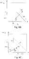
- the following formulaeare applied to pixels having a saturation value of about 0.5 or greater:
- FIG. 6Billustrates this color correction algorithm, showing a plot 190 of intensity verses saturation according to one embodiment of the invention.
- saturationis along the horizontal axis 192
- intensityruns along the vertical axis 194 .
- the line, I1 ⁇ S, is shown at 196 .
- the coordinates for the original saturation and intensity (S, I)are shown at point 198
- the coordinates for the new saturation and intensity (S n , I n )are shown at point 200 .
- the illustrated algorithmsresult in stronger darkening for more saturated areas.
- the corrected pixelis identified as remaining hard red.
- the vector ([0; 0]; [S n ; I n ])is shortened by approximately 30%.
- FIG. 6Cillustrates this color correction algorithm, showing a plot 210 of intensity verses saturation according to one embodiment of the invention.
- saturationis along the horizontal axis 212
- intensityruns along the vertical axis 214 .
- the vector, ([0; 0]; [S n ; I n ]),is shown at 216 .
- the line 1.01 ⁇ Sis shown at 224 .
- the coordinates for the original saturation and intensity (S, I)are shown at point 218
- the coordinates for the new saturation and intensity (Sn, In)are shown at point 220 .
- the illustrated algorithmsresult in dark red pixels to appear as virtually black pixels.
- the present inventionmay employ various computer-implemented operations involving data stored in computer systems. These operations are those requiring physical manipulation of physical quantities. Usually, though not necessarily, these quantities take the form of electrical or magnetic signals capable of being stored, transferred, combined, compared, and otherwise manipulated. Further, the manipulations performed are often referred to in terms, such as producing, identifying, determining, or comparing.
- the inventionalso relates to a device or an apparatus for performing these operations.
- the apparatusmay be specially constructed for the required purposes, or it may be a general-purpose computer selectively activated or configured by a computer program stored in the computer.
- various general-purpose machinesmay be used with computer programs written in accordance with the teachings herein, or it may be more convenient to construct a more specialized apparatus to perform the required operations.
- the inventioncan also be embodied as computer readable code on a computer readable medium.
- the computer readable mediumis any data storage device that can store data, which can thereafter be read by a computer system. Examples of the computer readable medium include read-only memory, random-access memory, CD-ROMs, CD-Rs, CD-RWs, DVD-ROM, DVD-R/RW, DVD-RAM, DVD+R/+RW, magnetic tapes, and other optical data storage devices.
- the computer readable mediumcan also be distributed over network coupled computer systems so that the computer readable code is stored and executed in a distributed fashion.
- the present inventionprovides a method and system for the automatic detection and correction of red eye effect in digital images.
- digital image use and distributionbecome more popular and commonplace, so too should the ease of processing and manipulation of digital images be for the average consumer.
- Embodiments of the present inventionprovide the automation to realize more user-friendly implementations.
- the inventionhas been described herein in terms of several exemplary embodiments. Other embodiments of the invention will be apparent to those skilled in the art from consideration of the specification and practice of the invention.
- the embodiments and preferred features described aboveshould be considered exemplary, with the invention being defined by the appended claims and equivalents thereof.
Landscapes
- Engineering & Computer Science (AREA)
- Computer Vision & Pattern Recognition (AREA)
- Health & Medical Sciences (AREA)
- General Health & Medical Sciences (AREA)
- Ophthalmology & Optometry (AREA)
- Human Computer Interaction (AREA)
- Physics & Mathematics (AREA)
- General Physics & Mathematics (AREA)
- Multimedia (AREA)
- Theoretical Computer Science (AREA)
- Image Processing (AREA)
Abstract
Description
- average for hue
- average for saturation
- average for intensity
- virtual weight center
- the real color center, which is defined as the point in the hard red area with the closest hue-saturation-intensity (HSI) value to the averages for the detected area
| Color_Dist = ABS(HA− Hp) + 0.3 * ABS((Sa+ Ia) − (Sp+ Ip)) | ||
| Ha = average hue | ||
| Hp = point's hue | ||
| Sa= average saturation | ||
| Sp= point's saturation | ||
| Ia- average intensity | ||
| Ip= point's intensity | ||
| If HueDuff = ABS(Hc− Hp) and SI_Radius2= (Sc− Sp)2+ (Ic− Ip)2then |
| (HueDuff < 0.02) | and | SI_Radius2< 0.452 | ||
| (HueDuff < 0.035) | and | SI_Radius2< 0.32 | ||
| (HueDiff < 0.045) | and | SI_Radius2< 0.12 | ||
| HueDiff = hue difference | ||||
| SI_Radius = saturation/intensity radius | ||||
| Hc = real color center hue | ||||
| Hp = point's hue | ||||
| Sc = real color center saturation | ||||
| Sp = point's saturation | ||||
| Ic = real color center intensity | ||||
| Ip = point's intensity | ||||
| TABLE 1 | |
| Filter | Use |
| SizeFilter | Filters out very large areas. In one |
| embodiment, filers out every area | |
| having an area-surrounding rectangle | |
| with a width or height exceeding a | |
| pre-defined value. In one embodi- | |
| ment, the pre-defined value is | |
| 50 pixels. | |
| CircleLikeFilter | Requires the identified red area to |
| have a circle-like shape. | |
| CircieLikeFilter uses an area- | |
| surrounding rectangle to further de- | |
| fine an identified circle-like shape. In | |
| one embodiment, requires that the | |
| longest dimension of the area- | |
| surrounding rectangle, either the | |
| length or height, is not more | |
| than 30% longer than the shorter | |
| dimension. In one embodiment, | |
| the CircleLikeFilter also requires | |
| that the virtual weight center of the | |
| identified red area does not deviate | |
| from the geometric center of the | |
| area-surrounding rectangle by more | |
| than 37.5% in either the horizontal | |
| or vertical orientation. | |
| StripesFilter | Filters out very oblong areas. The |
| StripesFilter uses an area-surrounding | |
| rectangle in addition to the values of | |
| the longest area dimension and the | |
| shortest area dimension. In one | |
| embodiment, the StripesFilter filters | |
| out any area having a significant dif- | |
| ference between the longest area | |
| dimension and the shortest area | |
| dimension. In one embodiment, | |
| the smaller the longest area | |
| dimension is (in pixels), the | |
| softer or weaker the requirement | |
| for the proportion between the | |
| dimensions. The following table | |
| summarizes values in accordance | |
| with one embodiment: | |
| Size | Proportion | |
| (pixels) | (shortest:longest) | |
| Less than 18 | More than 33% | |
| Less than 36 | More than 50% | |
| More than 35 | More than 75% |
| WeightFilter | Requires the red pixels within the |
| area-surrounding rectangle to have | |
| reasonable weight. In other words, | |
| the red pixels must represent a rea- | |
| sonable percentage of the total | |
| pixels. The WeightFilter also uses | |
| an area-surrounding rectangle, and | |
| the longest/shortest area dimensions. | |
| In one embodiment, the smaller the | |
| longest area dimension is (in pixels), | |
| the softer or weaker the requirement | |
| for the weight of the red pixels. The | |
| following table summarizes values in | |
| accordance with one embodiment: |
| Size | Red Pixels:Total | |
| (pixels) | Pixels | |
| Less than 18 | More than 33% | |
| Less than 36 | More than 40% | |
| More than 35 | More than 55% |
| SimpleBrightnessDispersionFilter | Filters out areas having insufficient |
| brightness dispersion. The | |
| SimpleBrightnessDispersionFilter | |
| calculates the deviation between the | |
| most bright and the least bright pixels | |
| in the identified red area, and then | |
| filters out the area if the proportion is | |
| less than 2. | |
| SpectralFilter | Filters out areas not matching pre- |
| defined spectral criteria. By way of | |
| example, the SpectralFilter will filter | |
| out identified red areas that are | |
| surrounded by pixels having color | |
| that are unlikely to be found on a hu- | |
| man face (e.g., bright, lime green). | |
| Sn= (3 + S − 3 * I)/4 | ||
| In= (3 + I − 3 * S)/4 | ||
| S = Original saturation | ||
| I = Original intensity | ||
| Sn= New saturation | ||
| Im= New intensity | ||
| Sn= 1 − I | ||
| In= 1 − S | ||
| S = Original saturation | ||
| I = Original intensity | ||
| Sn= New saturation | ||
| In= New intensity | ||
| Sn= (2 * S + 0.25)/3 | ||
| In= (2 * I + 0.25)/3 | ||
| S = Original saturation | ||
| I = Original intensity | ||
| Sn= New saturation | ||
| In= New intensity | ||
Claims (12)
Priority Applications (1)
| Application Number | Priority Date | Filing Date | Title |
|---|---|---|---|
| US10/665,849US7310443B1 (en) | 2003-09-17 | 2003-09-17 | Automatic red eye detection and correction in digital images |
Applications Claiming Priority (1)
| Application Number | Priority Date | Filing Date | Title |
|---|---|---|---|
| US10/665,849US7310443B1 (en) | 2003-09-17 | 2003-09-17 | Automatic red eye detection and correction in digital images |
Publications (1)
| Publication Number | Publication Date |
|---|---|
| US7310443B1true US7310443B1 (en) | 2007-12-18 |
Family
ID=38825980
Family Applications (1)
| Application Number | Title | Priority Date | Filing Date |
|---|---|---|---|
| US10/665,849Expired - Fee RelatedUS7310443B1 (en) | 2003-09-17 | 2003-09-17 | Automatic red eye detection and correction in digital images |
Country Status (1)
| Country | Link |
|---|---|
| US (1) | US7310443B1 (en) |
Cited By (43)
| Publication number | Priority date | Publication date | Assignee | Title |
|---|---|---|---|---|
| US20050117173A1 (en)* | 2003-10-27 | 2005-06-02 | Koichi Kugo | Image processing method and appparatus for red eye correction |
| US20050246637A1 (en)* | 2004-04-30 | 2005-11-03 | Microsoft Corporation | Rich end-user data views |
| US20060008173A1 (en)* | 2004-06-29 | 2006-01-12 | Canon Kabushiki Kaisha | Device and method for correcting image including person area |
| US20060008169A1 (en)* | 2004-06-30 | 2006-01-12 | Deer Anna Y | Red eye reduction apparatus and method |
| US7536036B2 (en)* | 2004-10-28 | 2009-05-19 | Fotonation Vision Limited | Method and apparatus for red-eye detection in an acquired digital image |
| US20090185049A1 (en)* | 2008-01-17 | 2009-07-23 | Canon Kabushiki Kaisha | Image processing apparatus and image processing method and image capturing apparatus |
| US7587085B2 (en) | 2004-10-28 | 2009-09-08 | Fotonation Vision Limited | Method and apparatus for red-eye detection in an acquired digital image |
| US7599577B2 (en) | 2005-11-18 | 2009-10-06 | Fotonation Vision Limited | Method and apparatus of correcting hybrid flash artifacts in digital images |
| US7599524B2 (en)* | 2003-04-04 | 2009-10-06 | Sarnoff Corporation | Method and apparatus for providing a robust object finder |
| US7630006B2 (en) | 1997-10-09 | 2009-12-08 | Fotonation Ireland Limited | Detecting red eye filter and apparatus using meta-data |
| US7689009B2 (en) | 2005-11-18 | 2010-03-30 | Fotonation Vision Ltd. | Two stage detection for photographic eye artifacts |
| US7738015B2 (en) | 1997-10-09 | 2010-06-15 | Fotonation Vision Limited | Red-eye filter method and apparatus |
| US20100172575A1 (en)* | 2009-01-07 | 2010-07-08 | Rastislav Lukac | Method Of Detecting Red-Eye Objects In Digital Images Using Color, Structural, And Geometric Characteristics |
| US7916190B1 (en) | 1997-10-09 | 2011-03-29 | Tessera Technologies Ireland Limited | Red-eye filter method and apparatus |
| US7920723B2 (en) | 2005-11-18 | 2011-04-05 | Tessera Technologies Ireland Limited | Two stage detection for photographic eye artifacts |
| US7962629B2 (en) | 2005-06-17 | 2011-06-14 | Tessera Technologies Ireland Limited | Method for establishing a paired connection between media devices |
| US7965875B2 (en) | 2006-06-12 | 2011-06-21 | Tessera Technologies Ireland Limited | Advances in extending the AAM techniques from grayscale to color images |
| US7970182B2 (en) | 2005-11-18 | 2011-06-28 | Tessera Technologies Ireland Limited | Two stage detection for photographic eye artifacts |
| US7995804B2 (en) | 2007-03-05 | 2011-08-09 | Tessera Technologies Ireland Limited | Red eye false positive filtering using face location and orientation |
| US8000526B2 (en) | 2007-11-08 | 2011-08-16 | Tessera Technologies Ireland Limited | Detecting redeye defects in digital images |
| US8036460B2 (en) | 2004-10-28 | 2011-10-11 | DigitalOptics Corporation Europe Limited | Analyzing partial face regions for red-eye detection in acquired digital images |
| US8055067B2 (en) | 2007-01-18 | 2011-11-08 | DigitalOptics Corporation Europe Limited | Color segmentation |
| US8081254B2 (en) | 2008-08-14 | 2011-12-20 | DigitalOptics Corporation Europe Limited | In-camera based method of detecting defect eye with high accuracy |
| US8126208B2 (en) | 2003-06-26 | 2012-02-28 | DigitalOptics Corporation Europe Limited | Digital image processing using face detection information |
| US8170294B2 (en) | 2006-11-10 | 2012-05-01 | DigitalOptics Corporation Europe Limited | Method of detecting redeye in a digital image |
| US8170302B1 (en)* | 2005-09-30 | 2012-05-01 | Ut-Battelle, Llc | System and method for generating motion corrected tomographic images |
| US8184900B2 (en) | 2006-02-14 | 2012-05-22 | DigitalOptics Corporation Europe Limited | Automatic detection and correction of non-red eye flash defects |
| US8212864B2 (en) | 2008-01-30 | 2012-07-03 | DigitalOptics Corporation Europe Limited | Methods and apparatuses for using image acquisition data to detect and correct image defects |
| US20120224081A1 (en)* | 2011-03-01 | 2012-09-06 | Hon Hai Precision Industry Co., Ltd. | Camera device and method for automatic red-eye avoidance of digital images |
| CN102893292A (en)* | 2010-04-30 | 2013-01-23 | 诺基亚公司 | Method, device and computer program product for compensating eye color defects |
| US8427721B2 (en) | 2007-08-17 | 2013-04-23 | Koninklijke Philips Electronics N.V. | Device and method for dynamically changing color |
| CN103069435A (en)* | 2010-06-28 | 2013-04-24 | 诺基亚公司 | Method, apparatus and computer program product for compensating eye color defects |
| US8503818B2 (en) | 2007-09-25 | 2013-08-06 | DigitalOptics Corporation Europe Limited | Eye defect detection in international standards organization images |
| US8520093B2 (en) | 2003-08-05 | 2013-08-27 | DigitalOptics Corporation Europe Limited | Face tracker and partial face tracker for red-eye filter method and apparatus |
| US8810640B2 (en) | 2011-05-16 | 2014-08-19 | Ut-Battelle, Llc | Intrinsic feature-based pose measurement for imaging motion compensation |
| US9412007B2 (en) | 2003-08-05 | 2016-08-09 | Fotonation Limited | Partial face detector red-eye filter method and apparatus |
| US10366296B2 (en) | 2016-03-31 | 2019-07-30 | Princeton Identity, Inc. | Biometric enrollment systems and methods |
| US10373008B2 (en) | 2016-03-31 | 2019-08-06 | Princeton Identity, Inc. | Systems and methods of biometric analysis with adaptive trigger |
| US10425814B2 (en) | 2014-09-24 | 2019-09-24 | Princeton Identity, Inc. | Control of wireless communication device capability in a mobile device with a biometric key |
| US10452936B2 (en) | 2016-01-12 | 2019-10-22 | Princeton Identity | Systems and methods of biometric analysis with a spectral discriminator |
| US10484584B2 (en) | 2014-12-03 | 2019-11-19 | Princeton Identity, Inc. | System and method for mobile device biometric add-on |
| US10607096B2 (en) | 2017-04-04 | 2020-03-31 | Princeton Identity, Inc. | Z-dimension user feedback biometric system |
| US10902104B2 (en) | 2017-07-26 | 2021-01-26 | Princeton Identity, Inc. | Biometric security systems and methods |
Citations (10)
| Publication number | Priority date | Publication date | Assignee | Title |
|---|---|---|---|---|
| US5432863A (en)* | 1993-07-19 | 1995-07-11 | Eastman Kodak Company | Automated detection and correction of eye color defects due to flash illumination |
| US5990973A (en)* | 1996-05-29 | 1999-11-23 | Nec Corporation | Red-eye detection/retouch apparatus |
| US6204858B1 (en)* | 1997-05-30 | 2001-03-20 | Adobe Systems Incorporated | System and method for adjusting color data of pixels in a digital image |
| US6407777B1 (en)* | 1997-10-09 | 2002-06-18 | Deluca Michael Joseph | Red-eye filter method and apparatus |
| US6631208B1 (en)* | 1998-05-29 | 2003-10-07 | Fuji Photo Film Co., Ltd. | Image processing method |
| US6665434B1 (en)* | 1999-03-11 | 2003-12-16 | Fuji Photo Film Co., Ltd. | Device, method, and recordium for correcting color imbalance of an image |
| US6728401B1 (en)* | 2000-08-17 | 2004-04-27 | Viewahead Technology | Red-eye removal using color image processing |
| US6798903B2 (en)* | 1999-12-24 | 2004-09-28 | Fuji Photo Film Co., Ltd. | Image processing method, image processing device, recording medium, and transmission medium |
| US6868178B1 (en)* | 1998-06-25 | 2005-03-15 | Cgk Computer Gesellschaft Konstanz Mbh | Method for processing image data |
| US6895112B2 (en)* | 2001-02-13 | 2005-05-17 | Microsoft Corporation | Red-eye detection based on red region detection with eye confirmation |
- 2003
- 2003-09-17USUS10/665,849patent/US7310443B1/ennot_activeExpired - Fee Related
Patent Citations (10)
| Publication number | Priority date | Publication date | Assignee | Title |
|---|---|---|---|---|
| US5432863A (en)* | 1993-07-19 | 1995-07-11 | Eastman Kodak Company | Automated detection and correction of eye color defects due to flash illumination |
| US5990973A (en)* | 1996-05-29 | 1999-11-23 | Nec Corporation | Red-eye detection/retouch apparatus |
| US6204858B1 (en)* | 1997-05-30 | 2001-03-20 | Adobe Systems Incorporated | System and method for adjusting color data of pixels in a digital image |
| US6407777B1 (en)* | 1997-10-09 | 2002-06-18 | Deluca Michael Joseph | Red-eye filter method and apparatus |
| US6631208B1 (en)* | 1998-05-29 | 2003-10-07 | Fuji Photo Film Co., Ltd. | Image processing method |
| US6868178B1 (en)* | 1998-06-25 | 2005-03-15 | Cgk Computer Gesellschaft Konstanz Mbh | Method for processing image data |
| US6665434B1 (en)* | 1999-03-11 | 2003-12-16 | Fuji Photo Film Co., Ltd. | Device, method, and recordium for correcting color imbalance of an image |
| US6798903B2 (en)* | 1999-12-24 | 2004-09-28 | Fuji Photo Film Co., Ltd. | Image processing method, image processing device, recording medium, and transmission medium |
| US6728401B1 (en)* | 2000-08-17 | 2004-04-27 | Viewahead Technology | Red-eye removal using color image processing |
| US6895112B2 (en)* | 2001-02-13 | 2005-05-17 | Microsoft Corporation | Red-eye detection based on red region detection with eye confirmation |
Cited By (78)
| Publication number | Priority date | Publication date | Assignee | Title |
|---|---|---|---|---|
| US7847840B2 (en) | 1997-10-09 | 2010-12-07 | Fotonation Vision Limited | Detecting red eye filter and apparatus using meta-data |
| US7738015B2 (en) | 1997-10-09 | 2010-06-15 | Fotonation Vision Limited | Red-eye filter method and apparatus |
| US7787022B2 (en) | 1997-10-09 | 2010-08-31 | Fotonation Vision Limited | Red-eye filter method and apparatus |
| US8203621B2 (en) | 1997-10-09 | 2012-06-19 | DigitalOptics Corporation Europe Limited | Red-eye filter method and apparatus |
| US7746385B2 (en) | 1997-10-09 | 2010-06-29 | Fotonation Vision Limited | Red-eye filter method and apparatus |
| US7804531B2 (en) | 1997-10-09 | 2010-09-28 | Fotonation Vision Limited | Detecting red eye filter and apparatus using meta-data |
| US7630006B2 (en) | 1997-10-09 | 2009-12-08 | Fotonation Ireland Limited | Detecting red eye filter and apparatus using meta-data |
| US7916190B1 (en) | 1997-10-09 | 2011-03-29 | Tessera Technologies Ireland Limited | Red-eye filter method and apparatus |
| US8264575B1 (en) | 1997-10-09 | 2012-09-11 | DigitalOptics Corporation Europe Limited | Red eye filter method and apparatus |
| US7847839B2 (en) | 1997-10-09 | 2010-12-07 | Fotonation Vision Limited | Detecting red eye filter and apparatus using meta-data |
| US7852384B2 (en) | 1997-10-09 | 2010-12-14 | Fotonation Vision Limited | Detecting red eye filter and apparatus using meta-data |
| US7599524B2 (en)* | 2003-04-04 | 2009-10-06 | Sarnoff Corporation | Method and apparatus for providing a robust object finder |
| US8126208B2 (en) | 2003-06-26 | 2012-02-28 | DigitalOptics Corporation Europe Limited | Digital image processing using face detection information |
| US8131016B2 (en) | 2003-06-26 | 2012-03-06 | DigitalOptics Corporation Europe Limited | Digital image processing using face detection information |
| US8224108B2 (en) | 2003-06-26 | 2012-07-17 | DigitalOptics Corporation Europe Limited | Digital image processing using face detection information |
| US9412007B2 (en) | 2003-08-05 | 2016-08-09 | Fotonation Limited | Partial face detector red-eye filter method and apparatus |
| US8520093B2 (en) | 2003-08-05 | 2013-08-27 | DigitalOptics Corporation Europe Limited | Face tracker and partial face tracker for red-eye filter method and apparatus |
| US20050117173A1 (en)* | 2003-10-27 | 2005-06-02 | Koichi Kugo | Image processing method and appparatus for red eye correction |
| US7486317B2 (en)* | 2003-10-27 | 2009-02-03 | Noritsu Koki, Co., Ltd. | Image processing method and apparatus for red eye correction |
| US20050246637A1 (en)* | 2004-04-30 | 2005-11-03 | Microsoft Corporation | Rich end-user data views |
| US8051406B2 (en)* | 2004-04-30 | 2011-11-01 | Microsoft Corporation | Rich end-user data views |
| US7580587B2 (en)* | 2004-06-29 | 2009-08-25 | Canon Kabushiki Kaisha | Device and method for correcting image including person area |
| US20060008173A1 (en)* | 2004-06-29 | 2006-01-12 | Canon Kabushiki Kaisha | Device and method for correcting image including person area |
| US20060008169A1 (en)* | 2004-06-30 | 2006-01-12 | Deer Anna Y | Red eye reduction apparatus and method |
| US7587085B2 (en) | 2004-10-28 | 2009-09-08 | Fotonation Vision Limited | Method and apparatus for red-eye detection in an acquired digital image |
| US7536036B2 (en)* | 2004-10-28 | 2009-05-19 | Fotonation Vision Limited | Method and apparatus for red-eye detection in an acquired digital image |
| US8265388B2 (en) | 2004-10-28 | 2012-09-11 | DigitalOptics Corporation Europe Limited | Analyzing partial face regions for red-eye detection in acquired digital images |
| US8036460B2 (en) | 2004-10-28 | 2011-10-11 | DigitalOptics Corporation Europe Limited | Analyzing partial face regions for red-eye detection in acquired digital images |
| US7962629B2 (en) | 2005-06-17 | 2011-06-14 | Tessera Technologies Ireland Limited | Method for establishing a paired connection between media devices |
| US8170302B1 (en)* | 2005-09-30 | 2012-05-01 | Ut-Battelle, Llc | System and method for generating motion corrected tomographic images |
| US7953252B2 (en)* | 2005-11-18 | 2011-05-31 | Tessera Technologies Ireland Limited | Two stage detection for photographic eye artifacts |
| US8126217B2 (en) | 2005-11-18 | 2012-02-28 | DigitalOptics Corporation Europe Limited | Two stage detection for photographic eye artifacts |
| US7970184B2 (en) | 2005-11-18 | 2011-06-28 | Tessera Technologies Ireland Limited | Two stage detection for photographic eye artifacts |
| US7970183B2 (en) | 2005-11-18 | 2011-06-28 | Tessera Technologies Ireland Limited | Two stage detection for photographic eye artifacts |
| US7599577B2 (en) | 2005-11-18 | 2009-10-06 | Fotonation Vision Limited | Method and apparatus of correcting hybrid flash artifacts in digital images |
| US8175342B2 (en) | 2005-11-18 | 2012-05-08 | DigitalOptics Corporation Europe Limited | Two stage detection for photographic eye artifacts |
| US7689009B2 (en) | 2005-11-18 | 2010-03-30 | Fotonation Vision Ltd. | Two stage detection for photographic eye artifacts |
| US8180115B2 (en) | 2005-11-18 | 2012-05-15 | DigitalOptics Corporation Europe Limited | Two stage detection for photographic eye artifacts |
| US7920723B2 (en) | 2005-11-18 | 2011-04-05 | Tessera Technologies Ireland Limited | Two stage detection for photographic eye artifacts |
| US7970182B2 (en) | 2005-11-18 | 2011-06-28 | Tessera Technologies Ireland Limited | Two stage detection for photographic eye artifacts |
| US7869628B2 (en) | 2005-11-18 | 2011-01-11 | Tessera Technologies Ireland Limited | Two stage detection for photographic eye artifacts |
| US8126218B2 (en) | 2005-11-18 | 2012-02-28 | DigitalOptics Corporation Europe Limited | Two stage detection for photographic eye artifacts |
| US7865036B2 (en) | 2005-11-18 | 2011-01-04 | Tessera Technologies Ireland Limited | Method and apparatus of correcting hybrid flash artifacts in digital images |
| US8131021B2 (en) | 2005-11-18 | 2012-03-06 | DigitalOptics Corporation Europe Limited | Two stage detection for photographic eye artifacts |
| US8160308B2 (en) | 2005-11-18 | 2012-04-17 | DigitalOptics Corporation Europe Limited | Two stage detection for photographic eye artifacts |
| US8184900B2 (en) | 2006-02-14 | 2012-05-22 | DigitalOptics Corporation Europe Limited | Automatic detection and correction of non-red eye flash defects |
| US7965875B2 (en) | 2006-06-12 | 2011-06-21 | Tessera Technologies Ireland Limited | Advances in extending the AAM techniques from grayscale to color images |
| US8170294B2 (en) | 2006-11-10 | 2012-05-01 | DigitalOptics Corporation Europe Limited | Method of detecting redeye in a digital image |
| US8055067B2 (en) | 2007-01-18 | 2011-11-08 | DigitalOptics Corporation Europe Limited | Color segmentation |
| US8233674B2 (en) | 2007-03-05 | 2012-07-31 | DigitalOptics Corporation Europe Limited | Red eye false positive filtering using face location and orientation |
| US7995804B2 (en) | 2007-03-05 | 2011-08-09 | Tessera Technologies Ireland Limited | Red eye false positive filtering using face location and orientation |
| US8427721B2 (en) | 2007-08-17 | 2013-04-23 | Koninklijke Philips Electronics N.V. | Device and method for dynamically changing color |
| US8503818B2 (en) | 2007-09-25 | 2013-08-06 | DigitalOptics Corporation Europe Limited | Eye defect detection in international standards organization images |
| US8036458B2 (en) | 2007-11-08 | 2011-10-11 | DigitalOptics Corporation Europe Limited | Detecting redeye defects in digital images |
| US8000526B2 (en) | 2007-11-08 | 2011-08-16 | Tessera Technologies Ireland Limited | Detecting redeye defects in digital images |
| US8106958B2 (en)* | 2008-01-17 | 2012-01-31 | Canon Kabushiki Kaisha | Image processing apparatus and image processing method and image capturing apparatus |
| US20090185049A1 (en)* | 2008-01-17 | 2009-07-23 | Canon Kabushiki Kaisha | Image processing apparatus and image processing method and image capturing apparatus |
| US8212864B2 (en) | 2008-01-30 | 2012-07-03 | DigitalOptics Corporation Europe Limited | Methods and apparatuses for using image acquisition data to detect and correct image defects |
| US8081254B2 (en) | 2008-08-14 | 2011-12-20 | DigitalOptics Corporation Europe Limited | In-camera based method of detecting defect eye with high accuracy |
| US20100172575A1 (en)* | 2009-01-07 | 2010-07-08 | Rastislav Lukac | Method Of Detecting Red-Eye Objects In Digital Images Using Color, Structural, And Geometric Characteristics |
| US8295593B2 (en) | 2009-01-07 | 2012-10-23 | Seiko Epson Corporation | Method of detecting red-eye objects in digital images using color, structural, and geometric characteristics |
| CN102893292B (en)* | 2010-04-30 | 2016-02-10 | 诺基亚技术有限公司 | Method and device for compensating eye color defects |
| CN102893292A (en)* | 2010-04-30 | 2013-01-23 | 诺基亚公司 | Method, device and computer program product for compensating eye color defects |
| CN103069435A (en)* | 2010-06-28 | 2013-04-24 | 诺基亚公司 | Method, apparatus and computer program product for compensating eye color defects |
| US9355456B2 (en) | 2010-06-28 | 2016-05-31 | Nokia Technologies Oy | Method, apparatus and computer program product for compensating eye color defects |
| US20120224081A1 (en)* | 2011-03-01 | 2012-09-06 | Hon Hai Precision Industry Co., Ltd. | Camera device and method for automatic red-eye avoidance of digital images |
| US8810640B2 (en) | 2011-05-16 | 2014-08-19 | Ut-Battelle, Llc | Intrinsic feature-based pose measurement for imaging motion compensation |
| US10425814B2 (en) | 2014-09-24 | 2019-09-24 | Princeton Identity, Inc. | Control of wireless communication device capability in a mobile device with a biometric key |
| US10484584B2 (en) | 2014-12-03 | 2019-11-19 | Princeton Identity, Inc. | System and method for mobile device biometric add-on |
| US10452936B2 (en) | 2016-01-12 | 2019-10-22 | Princeton Identity | Systems and methods of biometric analysis with a spectral discriminator |
| US10643087B2 (en) | 2016-01-12 | 2020-05-05 | Princeton Identity, Inc. | Systems and methods of biometric analysis to determine a live subject |
| US10643088B2 (en) | 2016-01-12 | 2020-05-05 | Princeton Identity, Inc. | Systems and methods of biometric analysis with a specularity characteristic |
| US10762367B2 (en) | 2016-01-12 | 2020-09-01 | Princeton Identity | Systems and methods of biometric analysis to determine natural reflectivity |
| US10943138B2 (en) | 2016-01-12 | 2021-03-09 | Princeton Identity, Inc. | Systems and methods of biometric analysis to determine lack of three-dimensionality |
| US10373008B2 (en) | 2016-03-31 | 2019-08-06 | Princeton Identity, Inc. | Systems and methods of biometric analysis with adaptive trigger |
| US10366296B2 (en) | 2016-03-31 | 2019-07-30 | Princeton Identity, Inc. | Biometric enrollment systems and methods |
| US10607096B2 (en) | 2017-04-04 | 2020-03-31 | Princeton Identity, Inc. | Z-dimension user feedback biometric system |
| US10902104B2 (en) | 2017-07-26 | 2021-01-26 | Princeton Identity, Inc. | Biometric security systems and methods |
Similar Documents
| Publication | Publication Date | Title |
|---|---|---|
| US7310443B1 (en) | Automatic red eye detection and correction in digital images | |
| US7224850B2 (en) | Modification of red-eye-effect in digital image | |
| Gaubatz et al. | Automatic red-eye detection and correction | |
| EP1810245B1 (en) | Detecting irises and pupils in human images | |
| US6728401B1 (en) | Red-eye removal using color image processing | |
| JP4019049B2 (en) | Detection and correction of red-eye features in digital images | |
| US7590284B2 (en) | Pupil color estimating device | |
| EP1721296B1 (en) | Correction of redeye in images of humans | |
| US7853048B2 (en) | Pupil color correction device and program | |
| EP1499110A2 (en) | Detecting and correcting red-eye in a digital-image | |
| WO2012124142A1 (en) | Image processing device and image processing method | |
| CN101390128B (en) | Detecting method and detecting system for positions of face parts | |
| WO2012124146A1 (en) | Image processing device and image processing method | |
| US20070122034A1 (en) | Face detection in digital images | |
| US8559668B2 (en) | Red-eye reduction using facial detection | |
| GB2453891A (en) | Pupil color correction device and program | |
| WO2005055143A1 (en) | Person head top detection method, head top detection system, and head top detection program | |
| Lecca et al. | An image contrast measure based on Retinex principles | |
| JP3510040B2 (en) | Image processing method | |
| JP2004240622A (en) | Image processing method, image processor and image processing program | |
| JP6098133B2 (en) | Face component extraction device, face component extraction method and program | |
| JP4530173B2 (en) | Method and system for detecting the position of a facial part | |
| KR101315464B1 (en) | Image processing method | |
| WO2005055144A1 (en) | Person face jaw detection method, jaw detection system, and jaw detection program | |
| JP3709656B2 (en) | Image processing device |
Legal Events
| Date | Code | Title | Description |
|---|---|---|---|
| AS | Assignment | Owner name:ROXIO, INC., CALIFORNIA Free format text:ASSIGNMENT OF ASSIGNORS INTEREST;ASSIGNORS:KRIS, MARK;MIRONOV, MIKHAIL;REEL/FRAME:014534/0099 Effective date:20030916 | |
| AS | Assignment | Owner name:SONIC SOLUTIONS, CALIFORNIA Free format text:ASSIGNMENT OF ASSIGNORS INTEREST;ASSIGNOR:ROXIO, INC.;REEL/FRAME:015499/0843 Effective date:20041217 Owner name:SONIC SOLUTIONS,CALIFORNIA Free format text:ASSIGNMENT OF ASSIGNORS INTEREST;ASSIGNOR:ROXIO, INC.;REEL/FRAME:015499/0843 Effective date:20041217 | |
| AS | Assignment | Owner name:JPMORGAN CHASE BANK, N.A., AS COLLATERAL AGENT, NE Free format text:SECURITY AGREEMENT;ASSIGNORS:ALL MEDIA GUIDE, LLC;DIVX, LLC;SONIC SOLUTIONS LLC;REEL/FRAME:026026/0111 Effective date:20110325 | |
| AS | Assignment | Owner name:SONIC SOLUTIONS LLC, CALIFORNIA Free format text:MERGER;ASSIGNOR:SPARTA ACQUISITION SUB, INC;REEL/FRAME:026533/0400 Effective date:20110218 | |
| REMI | Maintenance fee reminder mailed | ||
| FPAY | Fee payment | Year of fee payment:4 | |
| SULP | Surcharge for late payment | ||
| AS | Assignment | Owner name:COREL CORPORATION, CANADA Free format text:ASSIGNMENT OF ASSIGNORS INTEREST;ASSIGNOR:SONIC SOLUTIONS LLC;REEL/FRAME:027904/0924 Effective date:20100201 | |
| AS | Assignment | Owner name:VECTOR CC HOLDINGS IV, SRL, BARBADOS Free format text:ASSIGNMENT OF ASSIGNORS INTEREST;ASSIGNOR:COREL CORPORATION;REEL/FRAME:030427/0331 Effective date:20130507 Owner name:VECTOR CC HOLDINGS, SRL, BARBADOS Free format text:ASSIGNMENT OF ASSIGNORS INTEREST;ASSIGNOR:COREL CORPORATION;REEL/FRAME:030427/0331 Effective date:20130507 Owner name:VECTOR CC HOLDINGS III, SRL, BARBADOS Free format text:ASSIGNMENT OF ASSIGNORS INTEREST;ASSIGNOR:COREL CORPORATION;REEL/FRAME:030427/0331 Effective date:20130507 | |
| AS | Assignment | Owner name:8324450 CANADA INC., CANADA Free format text:ASSIGNMENT OF ASSIGNORS INTEREST;ASSIGNORS:VECTOR CC HOLDINGS, SRL;VECTOR CC HOLDINGS III, SRL;VECTOR CC HOLDINGS IV, SRL;REEL/FRAME:030427/0403 Effective date:20130507 | |
| AS | Assignment | Owner name:SONIC SOLUTIONS LLC, CALIFORNIA Free format text:RELEASE BY SECURED PARTY;ASSIGNOR:JPMORGAN CHASE BANK, N.A., AS COLLATERAL AGENT;REEL/FRAME:030591/0534 Effective date:20130607 Owner name:ALL MEDIA GUDE, LLC, CALIFORNIA Free format text:RELEASE BY SECURED PARTY;ASSIGNOR:JPMORGAN CHASE BANK, N.A., AS COLLATERAL AGENT;REEL/FRAME:030591/0534 Effective date:20130607 Owner name:DIVX, LLC, CALIFORNIA Free format text:RELEASE BY SECURED PARTY;ASSIGNOR:JPMORGAN CHASE BANK, N.A., AS COLLATERAL AGENT;REEL/FRAME:030591/0534 Effective date:20130607 | |
| AS | Assignment | Owner name:8324450 CANADA INC., CANADA Free format text:CORRECTIVE ASSIGNMENT TO CORRECT THE ASSIGNEE, AND REPLACE THE ASSIGNMENT PREVIOUSLY RECORDED ON REEL 030427 FRAME 0331. ASSIGNOR(S) HEREBY CONFIRMS THE ASSIGNMENT TO 8324450 CANADA INC;ASSIGNOR:COREL CORPORATION;REEL/FRAME:030986/0268 Effective date:20130725 | |
| AS | Assignment | Owner name:ALL MEDIA GUIDE, LLC, CALIFORNIA Free format text:PATENT RELEASE;ASSIGNOR:JPMORGAN CHASE BANK N.A., AS COLLATERAL AGENT;REEL/FRAME:033378/0685 Effective date:20140702 Owner name:DIVX, LLC, CALIFORNIA Free format text:PATENT RELEASE;ASSIGNOR:JPMORGAN CHASE BANK N.A., AS COLLATERAL AGENT;REEL/FRAME:033378/0685 Effective date:20140702 Owner name:SONIC SOLUTIONS LLC, CALIFORNIA Free format text:PATENT RELEASE;ASSIGNOR:JPMORGAN CHASE BANK N.A., AS COLLATERAL AGENT;REEL/FRAME:033378/0685 Effective date:20140702 | |
| AS | Assignment | Owner name:8324450 DELAWARE LLC, DELAWARE Free format text:ENTITY DOMICILE CHANGE;ASSIGNOR:8324450 CANADA INC.;REEL/FRAME:034651/0817 Effective date:20130927 | |
| REMI | Maintenance fee reminder mailed | ||
| LAPS | Lapse for failure to pay maintenance fees | ||
| STCH | Information on status: patent discontinuation | Free format text:PATENT EXPIRED DUE TO NONPAYMENT OF MAINTENANCE FEES UNDER 37 CFR 1.362 | |
| FP | Lapsed due to failure to pay maintenance fee | Effective date:20151218 | |
| AS | Assignment | Owner name:COREL SOFTWARE LLC, DELAWARE Free format text:CHANGE OF NAME;ASSIGNOR:8324450 CANADA INC.;REEL/FRAME:047675/0950 Effective date:20131022 | |
| AS | Assignment | Owner name:COREL CORPORATION, CANADA Free format text:ASSIGNMENT OF ASSIGNORS INTEREST;ASSIGNOR:COREL SOFTWARE LLC;REEL/FRAME:048067/0586 Effective date:20180905 |