US7309345B2 - Method and system for delivering an implant utilizing a lumen reducing member - Google Patents
Method and system for delivering an implant utilizing a lumen reducing memberDownload PDFInfo
- Publication number
- US7309345B2 US7309345B2US10/627,024US62702403AUS7309345B2US 7309345 B2US7309345 B2US 7309345B2US 62702403 AUS62702403 AUS 62702403AUS 7309345 B2US7309345 B2US 7309345B2
- Authority
- US
- United States
- Prior art keywords
- implant
- cavity
- vascular
- guide
- catheter
- Prior art date
- Legal status (The legal status is an assumption and is not a legal conclusion. Google has not performed a legal analysis and makes no representation as to the accuracy of the status listed.)
- Expired - Fee Related, expires
Links
- 239000007943implantSubstances0.000titleclaimsabstractdescription137
- 238000000034methodMethods0.000titleclaimsabstractdescription37
- 230000002792vascularEffects0.000claimsabstractdescription93
- 206010002329AneurysmDiseases0.000claimsabstractdescription72
- 230000003073embolic effectEffects0.000abstractdescription21
- 206010028980NeoplasmDiseases0.000abstractdescription5
- 208000009443Vascular MalformationsDiseases0.000abstractdescription4
- 239000000463materialSubstances0.000description17
- 210000004204blood vesselAnatomy0.000description10
- BASFCYQUMIYNBI-UHFFFAOYSA-NplatinumChemical compound[Pt]BASFCYQUMIYNBI-UHFFFAOYSA-N0.000description10
- 229920000642polymerPolymers0.000description9
- 230000006378damageEffects0.000description7
- 238000006073displacement reactionMethods0.000description7
- 230000000717retained effectEffects0.000description6
- 238000000576coating methodMethods0.000description5
- 208000007536ThrombosisDiseases0.000description4
- 239000011248coating agentSubstances0.000description4
- 102000004169proteins and genesHuman genes0.000description4
- 108090000623proteins and genesProteins0.000description4
- 238000011282treatmentMethods0.000description4
- 108010035532CollagenProteins0.000description3
- 102000008186CollagenHuman genes0.000description3
- 108010073385FibrinProteins0.000description3
- 102000009123FibrinHuman genes0.000description3
- BWGVNKXGVNDBDI-UHFFFAOYSA-NFibrin monomerChemical compoundCNC(=O)CNC(=O)CNBWGVNKXGVNDBDI-UHFFFAOYSA-N0.000description3
- 201000008450Intracranial aneurysmDiseases0.000description3
- 208000027418Wounds and injuryDiseases0.000description3
- 230000000740bleeding effectEffects0.000description3
- 230000017531blood circulationEffects0.000description3
- 229920001436collagenPolymers0.000description3
- 229950003499fibrinDrugs0.000description3
- 150000004676glycansChemical class0.000description3
- 239000000203mixtureSubstances0.000description3
- 239000002121nanofiberSubstances0.000description3
- 229910052697platinumInorganic materials0.000description3
- 229920001282polysaccharidePolymers0.000description3
- 239000005017polysaccharideSubstances0.000description3
- 210000001519tissueAnatomy0.000description3
- 206010053567CoagulopathiesDiseases0.000description2
- KDLHZDBZIXYQEI-UHFFFAOYSA-NPalladiumChemical compound[Pd]KDLHZDBZIXYQEI-UHFFFAOYSA-N0.000description2
- -1PolypropylenePolymers0.000description2
- 229910001260Pt alloyInorganic materials0.000description2
- 229910001080W alloyInorganic materials0.000description2
- TZCXTZWJZNENPQ-UHFFFAOYSA-Lbarium sulfateChemical compound[Ba+2].[O-]S([O-])(=O)=OTZCXTZWJZNENPQ-UHFFFAOYSA-L0.000description2
- 239000008280bloodSubstances0.000description2
- 210000004369bloodAnatomy0.000description2
- 230000035602clottingEffects0.000description2
- 208000014674injuryDiseases0.000description2
- 238000003780insertionMethods0.000description2
- 230000037431insertionEffects0.000description2
- 239000007788liquidSubstances0.000description2
- 229910052751metalInorganic materials0.000description2
- 239000002184metalSubstances0.000description2
- 150000002739metalsChemical class0.000description2
- 230000002093peripheral effectEffects0.000description2
- WFKWXMTUELFFGS-UHFFFAOYSA-NtungstenChemical compound[W]WFKWXMTUELFFGS-UHFFFAOYSA-N0.000description2
- 229910052721tungstenInorganic materials0.000description2
- 239000010937tungstenSubstances0.000description2
- KIUKXJAPPMFGSW-DNGZLQJQSA-N(2S,3S,4S,5R,6R)-6-[(2S,3R,4R,5S,6R)-3-Acetamido-2-[(2S,3S,4R,5R,6R)-6-[(2R,3R,4R,5S,6R)-3-acetamido-2,5-dihydroxy-6-(hydroxymethyl)oxan-4-yl]oxy-2-carboxy-4,5-dihydroxyoxan-3-yl]oxy-5-hydroxy-6-(hydroxymethyl)oxan-4-yl]oxy-3,4,5-trihydroxyoxane-2-carboxylic acidChemical compoundCC(=O)N[C@H]1[C@H](O)O[C@H](CO)[C@@H](O)[C@@H]1O[C@H]1[C@H](O)[C@@H](O)[C@H](O[C@H]2[C@@H]([C@@H](O[C@H]3[C@@H]([C@@H](O)[C@H](O)[C@H](O3)C(O)=O)O)[C@H](O)[C@@H](CO)O2)NC(C)=O)[C@@H](C(O)=O)O1KIUKXJAPPMFGSW-DNGZLQJQSA-N0.000description1
- SQDAZGGFXASXDW-UHFFFAOYSA-N5-bromo-2-(trifluoromethoxy)pyridineChemical compoundFC(F)(F)OC1=CC=C(Br)C=N1SQDAZGGFXASXDW-UHFFFAOYSA-N0.000description1
- FHVDTGUDJYJELY-UHFFFAOYSA-N6-{[2-carboxy-4,5-dihydroxy-6-(phosphanyloxy)oxan-3-yl]oxy}-4,5-dihydroxy-3-phosphanyloxane-2-carboxylic acidChemical compoundO1C(C(O)=O)C(P)C(O)C(O)C1OC1C(C(O)=O)OC(OP)C(O)C1OFHVDTGUDJYJELY-UHFFFAOYSA-N0.000description1
- 229910000014Bismuth subcarbonateInorganic materials0.000description1
- 229920000049Carbon (fiber)Polymers0.000description1
- 229920002101ChitinPolymers0.000description1
- 229920001661ChitosanPolymers0.000description1
- 229920001287Chondroitin sulfatePolymers0.000description1
- 108010014258ElastinProteins0.000description1
- 102000016942ElastinHuman genes0.000description1
- 108010049003FibrinogenProteins0.000description1
- 102000008946FibrinogenHuman genes0.000description1
- 108010067306FibronectinsProteins0.000description1
- 102000016359FibronectinsHuman genes0.000description1
- 108010010803GelatinProteins0.000description1
- 102000007547LamininHuman genes0.000description1
- 108010085895LamininProteins0.000description1
- 241001465754MetazoaSpecies0.000description1
- 229920002732PolyanhydridePolymers0.000description1
- 229920002614Polyether block amidePolymers0.000description1
- 229920000954PolyglycolidePolymers0.000description1
- 229920000331PolyhydroxybutyratePolymers0.000description1
- 239000004743PolypropyleneSubstances0.000description1
- BQCADISMDOOEFD-UHFFFAOYSA-NSilverChemical compound[Ag]BQCADISMDOOEFD-UHFFFAOYSA-N0.000description1
- 241000219793TrifoliumSpecies0.000description1
- 108010031318VitronectinProteins0.000description1
- 102100035140VitronectinHuman genes0.000description1
- 206010052428WoundDiseases0.000description1
- 229940072056alginateDrugs0.000description1
- 229920000615alginic acidPolymers0.000description1
- 235000010443alginic acidNutrition0.000description1
- 229910045601alloyInorganic materials0.000description1
- 239000000956alloySubstances0.000description1
- 230000004075alterationEffects0.000description1
- 210000001367arteryAnatomy0.000description1
- 229920000249biocompatible polymerPolymers0.000description1
- 230000015572biosynthetic processEffects0.000description1
- 229910000416bismuth oxideInorganic materials0.000description1
- MGLUJXPJRXTKJM-UHFFFAOYSA-Lbismuth subcarbonateChemical compoundO=[Bi]OC(=O)O[Bi]=OMGLUJXPJRXTKJM-UHFFFAOYSA-L0.000description1
- 229940036358bismuth subcarbonateDrugs0.000description1
- 230000036770blood supplyEffects0.000description1
- 210000001124body fluidAnatomy0.000description1
- 208000021138brain aneurysmDiseases0.000description1
- 210000005013brain tissueAnatomy0.000description1
- 239000004917carbon fiberSubstances0.000description1
- 210000001715carotid arteryAnatomy0.000description1
- 210000004027cellAnatomy0.000description1
- 229920002678cellulosePolymers0.000description1
- 239000001913celluloseSubstances0.000description1
- 230000002490cerebral effectEffects0.000description1
- 229940059329chondroitin sulfateDrugs0.000description1
- 229920001577copolymerPolymers0.000description1
- 238000013461designMethods0.000description1
- TYIXMATWDRGMPF-UHFFFAOYSA-Ndibismuth;oxygen(2-)Chemical compound[O-2].[O-2].[O-2].[Bi+3].[Bi+3]TYIXMATWDRGMPF-UHFFFAOYSA-N0.000description1
- 229920002549elastinPolymers0.000description1
- 238000005868electrolysis reactionMethods0.000description1
- 210000003038endotheliumAnatomy0.000description1
- 238000005516engineering processMethods0.000description1
- 210000001105femoral arteryAnatomy0.000description1
- 239000000835fiberSubstances0.000description1
- 229940012952fibrinogenDrugs0.000description1
- 210000002950fibroblastAnatomy0.000description1
- 239000002657fibrous materialSubstances0.000description1
- 239000012530fluidSubstances0.000description1
- 238000002594fluoroscopyMethods0.000description1
- 229920000159gelatinPolymers0.000description1
- 239000008273gelatinSubstances0.000description1
- 235000019322gelatineNutrition0.000description1
- 235000011852gelatine dessertsNutrition0.000description1
- PCHJSUWPFVWCPO-UHFFFAOYSA-NgoldChemical compound[Au]PCHJSUWPFVWCPO-UHFFFAOYSA-N0.000description1
- 229910052737goldInorganic materials0.000description1
- 239000010931goldSubstances0.000description1
- 230000035876healingEffects0.000description1
- 230000000004hemodynamic effectEffects0.000description1
- 229920002674hyaluronanPolymers0.000description1
- 229960003160hyaluronic acidDrugs0.000description1
- 238000011065in-situ storageMethods0.000description1
- 238000013508migrationMethods0.000description1
- 230000005012migrationEffects0.000description1
- 238000012986modificationMethods0.000description1
- 230000004048modificationEffects0.000description1
- 230000001537neural effectEffects0.000description1
- 229910001000nickel titaniumInorganic materials0.000description1
- 229920001778nylonPolymers0.000description1
- 229910052763palladiumInorganic materials0.000description1
- 229920001308poly(aminoacid)Polymers0.000description1
- 239000005014poly(hydroxyalkanoate)Substances0.000description1
- 239000005015poly(hydroxybutyrate)Substances0.000description1
- 229920000218poly(hydroxyvalerate)Polymers0.000description1
- 229920000747poly(lactic acid)Polymers0.000description1
- 229920002463poly(p-dioxanone) polymerPolymers0.000description1
- 229920001230polyarylatePolymers0.000description1
- 229920001610polycaprolactonePolymers0.000description1
- 239000004632polycaprolactoneSubstances0.000description1
- 229920000515polycarbonatePolymers0.000description1
- 239000004417polycarbonateSubstances0.000description1
- 239000000622polydioxanoneSubstances0.000description1
- 229920000728polyesterPolymers0.000description1
- 239000004633polyglycolic acidSubstances0.000description1
- 229920000903polyhydroxyalkanoatePolymers0.000description1
- 239000004626polylactic acidSubstances0.000description1
- 229920001155polypropylenePolymers0.000description1
- 230000000541pulsatile effectEffects0.000description1
- 210000002321radial arteryAnatomy0.000description1
- 238000002601radiographyMethods0.000description1
- 229910052702rheniumInorganic materials0.000description1
- WUAPFZMCVAUBPE-UHFFFAOYSA-Nrhenium atomChemical compound[Re]WUAPFZMCVAUBPE-UHFFFAOYSA-N0.000description1
- 229910052703rhodiumInorganic materials0.000description1
- 239000010948rhodiumSubstances0.000description1
- MHOVAHRLVXNVSD-UHFFFAOYSA-Nrhodium atomChemical compound[Rh]MHOVAHRLVXNVSD-UHFFFAOYSA-N0.000description1
- 229910052709silverInorganic materials0.000description1
- 239000004332silverSubstances0.000description1
- 239000010935stainless steelSubstances0.000description1
- 229910001220stainless steelInorganic materials0.000description1
- 238000006467substitution reactionMethods0.000description1
- 239000000758substrateSubstances0.000description1
- 229920001059synthetic polymerPolymers0.000description1
- 229910052715tantalumInorganic materials0.000description1
- GUVRBAGPIYLISA-UHFFFAOYSA-Ntantalum atomChemical compound[Ta]GUVRBAGPIYLISA-UHFFFAOYSA-N0.000description1
- 230000002885thrombogenetic effectEffects0.000description1
- 150000003673urethanesChemical class0.000description1
- 210000003462veinAnatomy0.000description1
- 230000029663wound healingEffects0.000description1
Images


Classifications
- A—HUMAN NECESSITIES
- A61—MEDICAL OR VETERINARY SCIENCE; HYGIENE
- A61B—DIAGNOSIS; SURGERY; IDENTIFICATION
- A61B17/00—Surgical instruments, devices or methods
- A61B17/12—Surgical instruments, devices or methods for ligaturing or otherwise compressing tubular parts of the body, e.g. blood vessels or umbilical cord
- A61B17/12022—Occluding by internal devices, e.g. balloons or releasable wires
- A61B17/12099—Occluding by internal devices, e.g. balloons or releasable wires characterised by the location of the occluder
- A61B17/12109—Occluding by internal devices, e.g. balloons or releasable wires characterised by the location of the occluder in a blood vessel
- A61B17/12113—Occluding by internal devices, e.g. balloons or releasable wires characterised by the location of the occluder in a blood vessel within an aneurysm
- A—HUMAN NECESSITIES
- A61—MEDICAL OR VETERINARY SCIENCE; HYGIENE
- A61B—DIAGNOSIS; SURGERY; IDENTIFICATION
- A61B17/00—Surgical instruments, devices or methods
- A61B17/12—Surgical instruments, devices or methods for ligaturing or otherwise compressing tubular parts of the body, e.g. blood vessels or umbilical cord
- A61B17/12022—Occluding by internal devices, e.g. balloons or releasable wires
- A61B17/12099—Occluding by internal devices, e.g. balloons or releasable wires characterised by the location of the occluder
- A61B17/12109—Occluding by internal devices, e.g. balloons or releasable wires characterised by the location of the occluder in a blood vessel
- A—HUMAN NECESSITIES
- A61—MEDICAL OR VETERINARY SCIENCE; HYGIENE
- A61B—DIAGNOSIS; SURGERY; IDENTIFICATION
- A61B17/00—Surgical instruments, devices or methods
- A61B17/12—Surgical instruments, devices or methods for ligaturing or otherwise compressing tubular parts of the body, e.g. blood vessels or umbilical cord
- A61B17/12022—Occluding by internal devices, e.g. balloons or releasable wires
- A61B17/12131—Occluding by internal devices, e.g. balloons or releasable wires characterised by the type of occluding device
- A61B17/1214—Coils or wires
- A61B17/12145—Coils or wires having a pre-set deployed three-dimensional shape
- A—HUMAN NECESSITIES
- A61—MEDICAL OR VETERINARY SCIENCE; HYGIENE
- A61F—FILTERS IMPLANTABLE INTO BLOOD VESSELS; PROSTHESES; DEVICES PROVIDING PATENCY TO, OR PREVENTING COLLAPSING OF, TUBULAR STRUCTURES OF THE BODY, e.g. STENTS; ORTHOPAEDIC, NURSING OR CONTRACEPTIVE DEVICES; FOMENTATION; TREATMENT OR PROTECTION OF EYES OR EARS; BANDAGES, DRESSINGS OR ABSORBENT PADS; FIRST-AID KITS
- A61F2/00—Filters implantable into blood vessels; Prostheses, i.e. artificial substitutes or replacements for parts of the body; Appliances for connecting them with the body; Devices providing patency to, or preventing collapsing of, tubular structures of the body, e.g. stents
- A61F2/95—Instruments specially adapted for placement or removal of stents or stent-grafts
- A61F2/962—Instruments specially adapted for placement or removal of stents or stent-grafts having an outer sleeve
- A61F2/966—Instruments specially adapted for placement or removal of stents or stent-grafts having an outer sleeve with relative longitudinal movement between outer sleeve and prosthesis, e.g. using a push rod
- A—HUMAN NECESSITIES
- A61—MEDICAL OR VETERINARY SCIENCE; HYGIENE
- A61B—DIAGNOSIS; SURGERY; IDENTIFICATION
- A61B17/00—Surgical instruments, devices or methods
- A61B17/12—Surgical instruments, devices or methods for ligaturing or otherwise compressing tubular parts of the body, e.g. blood vessels or umbilical cord
- A61B17/12022—Occluding by internal devices, e.g. balloons or releasable wires
- A61B2017/1205—Introduction devices
- A61B2017/12054—Details concerning the detachment of the occluding device from the introduction device
- A61B2017/12063—Details concerning the detachment of the occluding device from the introduction device electrolytically detachable
Definitions
- the field of the inventionrelates to implantable devices, and more particularly, to a method and system for inserting a delivery sheath or catheter through a vascular body using a lumen-reducing catheter and delivering an implantable device through the delivery catheter or the lumen-reducing catheter.
- Intracranial aneurysmsmay rupture causing significant bleeding. The significant bleeding may permanently damage the surrounding brain tissue, possibly causing serious injury and death. Intracranial aneurysms may be particularly difficult to access and treat when they are formed in remote cerebral blood vessels. If left untreated, hemodynamic forces of normal pulsatile blood flow can rupture fragile tissue in the area of the aneurysm causing a stroke.
- vaso-occlusive devicesare surgical implants that are delivered through a catheter in a blood vessel or vascular cavity and placed within aneurysm to form a thrombus and occlude the aneurysm.
- a guide wireis inserted through a vascular cavity.
- An outer catheter or sheathis guided by the wire and inserted through the vascular cavity, and the implant is pushed or otherwise forced through the interior of the catheter to an aneurysm site.
- the applications and treatments using conventional sheathsmay be limited since it may not be possible to insert the sheath through narrow or curved vascular cavity sections to an aneurysm site. Consequently, the aneurysm or containment site can be left untreated or can be treated while causing damage to other blood vessel sections, in the process possibly leading to more serious injury, stroke and death. These problems are amplified with smaller vessels and vessels having sharp turns and when larger implants are utilized.
- implantsmay not be properly retained within an aneurysm as a result of the width or the aneurysm neck. For example, an implant may be improperly secured or inadvertently released from the aneurysm as a result of slipping through a wide aneurysm neck.
- an implantsuch as a vaso-occlusive implant or an embolic containment implant that facilitates delivery of a vaso-occlusive implant
- an implantsuch as a vaso-occlusive implant
- a guidea first member having a distal end and a proximal end and defining a first cavity
- a second memberhaving a distal end and a proximal end and defining a second cavity are advanced along the guide and through the vascular space to the vascular site.
- the second memberis inserted through the first member.
- the first membercan be a first annular catheter defining the first cavity
- the second membercan be a second annular catheter defining the second cavity.
- the first annular catheterhas an outer diameter of about 0.66 mm to about 1.3 mm
- the first cavityhas a diameter of about 0.5 mm to about 1.25 mm
- the second annular catheterhas an outer diameter of about 0.45 mm to about 1.20 mm
- the second cavityhaving a diameter of about 0.35 mm to about 1.0 mm.
- the second memberreduces radial movement of the first member relative to the guide, and the guide is confined to the second cavity when the first and second members are inserted through the vascular space. Further, the distal ends of the first and second members can be generally aligned when the are advanced along the guide.
- a first memberhas a distal end and a proximal end and defines a first cavity.
- a second memberhas a distal end and a proximal end and defines a second cavity. The second member is insertable within the first cavity. The distal ends of the first and second members are advanced along a guide and through the vascular space to the vascular site, thereby advancing the first implant to the vascular site.
- the first implantcan be advanced by the distal end of the first member, the distal end of the second member, or the distal ends of both members. Further, the distal ends of the first and second members can be generally aligned when they are advanced along the guide.
- a second implantsuch as a vaso-occlusive implant, can also be inserted through the second cavity of the second member into the vascular site.
- the second implantis contained within the vascular site by the first implant.
- the second memberreduces the radial movement of the first member relative to the guide, and the guide is confined to the second cavity when the first and second members are inserted through the vascular space.
- the first membercan be a first annular catheter defining the first cavity
- the second membercan be a second annular catheter defining the second cavity.
- the first annular catheterhas an outer diameter of about 0.66 mm to about 1.3 mm
- the first cavityhas a diameter of about 0.5 mm to about 1.25 mm
- the second annular catheterhas an outer diameter of about 0.45 mm to about 1.20 mm
- the second cavityhaving a diameter of about 0.35 mm to about 1.0 mm.
- FIG. 1Ais a front view and FIG. 1B is a partial cross-sectional view of a system having a cavity-reducing or lumen-reducing sheath according to the present invention
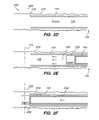
- FIGS. 2A-Jare partial cross-sectional views showing the manner in which an implant is inserted through a vascular space to a vascular site using an outer or delivery sheath, a lumen reducing sheath and guide wire;
- FIGS. 3A-Fshow how an embolic containment implant is delivered to a neck of an aneurysm and a second implant is then inserted into and retained within an aneurysm using a system and a method according to the present invention.
- a system or assembly 100 of the present inventionincludes a first or delivery member 110 , such as an outer, annular catheter or sheath, a second or reducing member 120 , such as an inner, annular catheter or sheath, and a guide 130 , such as a guide wire.
- the system 100is used to deliver an implant (not shown) through a vascular space to a vascular site, such as an aneurysm, tumor, a site for capturing embolic debris, or other vascular malformation (generally vascular site).
- the present inventionis suitable for delivering or advancing various devices or implants into the body of a patient for different applications.
- the present inventioncan be used to deliver a vaso-occlusive implant, such as a coil and a liquid, to treat or occlude an aneurysm.
- the present inventioncan be used to deliver an embolic containment implant which facilitates delivery of a vaso-occlusive implant by, for example, reducing the size of the aperture formed by a neck of an aneurysm to contain the vaso-occlusive device in the aneurysm without risk of embolic migration.
- an embolic containment implantwould be positioned slightly inside the neck of the aneurysm.
- the present inventioncan be used to deliver a stent to ensure that a vessel remains open or unblocked.
- the stentcan also be used to help contain subsequent delivery of embolic materials (liquids, coils) into the aneurysm, similar to an embolic containment implant. Unlike the embolic containment system, however, the stent is placed outside the neck of the aneurysm or into the parent vessel.
- An “implant” in this specificationrefers to the various types of implants that can be delivered with the present invention.
- the implantcan be delivered into the body through various entry points, e.g., percutaneously through a peripheral vessel, such as a femoral, carotid, or radial artery, or other vein, artery or vascular space, to treat various vascular sites.
- a peripheral vesselsuch as a femoral, carotid, or radial artery, or other vein, artery or vascular space
- the present inventioncan be used to treat humans and animals.
- This specificationdescribes and illustrates a system and method related to treating a vascular cranial aneurysm sites with various implants for purposes of explanation and illustration, but the invention is not so limited.
- Various guides 130can be used with the system 100 of the present invention.
- One exemplary guideis a guide wire, such as a 1014 to GC18 guide wire, having diameters from about 0.01′′ to about 0.018′′.
- the guide wirecan also have a rounded or modified tip, such as a “J hook” or a smoothed or rounded tip that allows the guide wire to be inserted through a vascular space more smoothly.
- Other exemplary guidesinclude a guiding catheter or other guide rail.
- the particular guide 130 that is utilizedmay depend on the particular application. Thus, the invention is not limited to using a particular guide 130 , but this specification refers to and illustrates a guide wire for purposes of explanation and illustration.
- the outer, first or delivery catheter or sheath(“delivery catheter 110 ”) may be a micro-catheter or other elongated delivery device.
- the size of the delivery catheter 110can vary depending on the particular patient, treatment, and implant to be delivered to the aneurysm site. For example, when accessing a brain aneurysm in a small vessel, an appropriately sized delivery catheter 110 can be quite small and flexible.
- Exemplary delivery catheters 110 for treating cranial aneurismsare 3.0 F to 3.8 F catheters having an outer diameter (OD) 112 from about 1.0 mm to about 1.3 mm.
- the inner diameter (ID) 114 of the lumen or cavity 116 of the delivery catheter 110can be from about 0.8 mm to about 1.1 mm.
- Different delivery catheters 110 with different IDs 114 and ODs 112can be utilized depending on the particular application and size of the implant. .
- the ID 114 of the delivery catheter 110should be made large enough to accommodate a second or cavity-reducing or lumen-reducing catheter (“reducing catheter 120 ”) and the implant.
- the delivery catheter 110can be made of different materials and have various coating to facilitate insertion through a vascular space.
- Exemplary delivery catheter 110 materialsinclude Polypropylene, PE, Urethanes, Nylons, and Pebax.
- One exemplary coating applied to the outer surface of the delivery catheter 110is a hydrophilic coating. Persons of ordinary skill in the art will recognize that various delivery catheter 110 sizes, materials, and coatings can be utilized depending on the particular application and treatment.
- the second or reducing catheter 120is inserted within the cavity or lumen 116 defined by the delivery catheter 110 .
- the Outer Diameter (OD) 122 of the reducing catheter 120should be smaller than the ID 114 of the delivery catheter 110 so that the reducing catheter 120 can be inserted through the lumen 116 of the delivery catheter 110 .
- the delivery catheter 110defines a lumen 116 with an ID 114 from about 0.5 mm to about 0.8 mm, then the OD 122 of the reducing catheter 120 can be from about 0.66 mm to about 1.0 mm.
- the delivery catheter 110defines a cavity having an ID 114 of about 0.033′′
- the reducing catheter 120defines a reduced cavity or lumen 126 having an ID 124 from about 0.012′′ to about 0.021′′.
- radial movemente.g., up-down, side-to-side
- the amount of movement or play between the guide wire 130 and the delivery catheter 110is reduced so that the delivery catheter 110 can be inserted through a vascular space more easily and efficiently.
- the area of the first lumen 120is reduced by about 35% to about 75%.
- Persons of ordinary skill in the artwill recognize that different sizes and thickness of the catheters 110 and 120 can produce reduced cavities 126 of different sizes. Further, the gap between the catheters 110 and 120 can be adjusted as needed.
- the delivery and reducing catheters 110 and 120are positioned in a vessel so that the distal ends 118 and 128 of the catheters 110 and 120 are advanced over or otherwise in conjunction with a guide wire 130 to a vascular site.
- the distal ends 118 and 128 of the delivery and reducing catheters 110 and 120may be generally aligned with each other when being advanced through the vascular space over the guide wire 130 .
- the lumen-reducing catheter 120can also extend somewhat ahead of the delivery catheter 110 if necessary.
- vaso-occlusive implantIf a vaso-occlusive implant is being delivered to an aneurysm site, the reducing catheter 120 and the guide wire 130 are removed after they are properly positioned at the vascular site.
- a displacement membersuch as a pusher wire, advances the implant through the delivery catheter 110 .
- Various other displacement memberscan be utilized, such as a plunger that is attached to the guide wire 130 to advance the implant or fluid pressure through the delivery catheter 110 .
- vaso-occlusive implants 230When vaso-occlusive implants 230 are placed within or at a neck an of aneurysm 220 , they tend to induce the formation of fibrin network (clot or thrombus).
- the thrombusprovides a high-surface-area substrate on which the cells responsible for wound healing (such as fibroblasts) migrate and proliferate as they deposit collagen to replace the clot with more stable collagenous fibrous tissue.
- the containment implantIn cases involving a first implant being delivered to an aneurysm site to retain or contain a second implant within an aneurysm site, the containment implant is inserted through a vessel together with the delivery and lumen-reducing catheters to a neck of the aneurysm.
- the containment implantreduces the width of a neck of an aneurysm.
- a second implantsuch as a vaso-occlusive implant, is delivered through the reducing catheter to the aneurysm site and is secured or retained within the aneurysm by the previously deployed containment implant.
- FIGS. 2A-Iillustrate a method 200 and components of the system 100 at different stages showing in further detail how the system 100 is used to advance an implant, such as a stent, a coil, a filter or an implant that removes part of a vessel clot, to an aneurysm site.
- an implantsuch as a stent, a coil, a filter or an implant that removes part of a vessel clot, to an aneurysm site.
- the guide wire 130is inserted and fed through a vascular cavity or space 210 .
- the delivery catheter 110 and the reducing catheter 120are advanced over the guide wire 130 .
- the delivery and lumen-reducing catheters 110 and 120can be advanced together over the guide wire 130 , and the catheters 110 and 120 can be generally aligned with each other as they are advanced over the guide wire 130 .
- the reducing catheter 120can also extend somewhat ahead of the delivery catheter if necessary.
- the distal ends 118 and 128 of the delivery and reducing catheters 110 and 120are positioned at or near the vascular site 220 (shown generally as a dotted line.)
- the site 220is then said to be catheterized.
- the reducing catheter 120 and the guide wire 130are retracted from the site 220 after the outer catheter 110 is positioned and, as shown in FIG. 2D , removed or pulled from the cavity 116 of the delivery catheter 110 .
- the delivery catheter 110remains inserted within the vascular cavity 210 at the vascular site 220 , and the lumen 116 of the delivery catheter 110 is empty.
- the guide wire 130is re-inserted (or a different guide wire is inserted) into the lumen or cavity 116 of the delivery catheter 110 .
- An implant 230such as a vaso-occlusive coil, a stent, a filter, or an implant that removes part of a vessel clot is inserted into the proximate end 119 of the delivery catheter 110 .
- An insertion or displacement device 240advances the implant 230 along the guide wire 130 and through the cavity 116 of the delivery catheter 110 until the implant 230 exits or reaches the distal end 118 of the outer catheter 110 , as shown in FIG. 2F .
- the implant 230is pushed by the displacement device 240 through the cavity 116 of the delivery catheter 110 without a guide wire 130 , however, a guide wire that directs the implant 230 to the site 220 is shown for purposes of illustration.
- the displacement device 240is detached or released from the implant 230 (if necessary), and the displacement device 240 and the guide wire 130 are removed from the lumen 116 of the delivery catheter 110 .
- the implant 230remains at the vascular site 220 .
- the delivery catheter 110may be removed from the vascular space 210 , leaving the implant 230 at the site 220 .
- the implante.g., a filter
- FIGS. 3A-Fillustrate an alternative embodiment of the present invention directed to delivering an embolic containment implant and a second implant, such as a vaso-occlusive implant, utilizing a lumen-reducing catheter.
- a containment implantcan be delivered to the aneurysm neck to reduce the width of the neck, and a vaso-occlusive coil can then be delivered through the lumen reducing catheter into the aneurysm.
- the containment implantreduces the width of the neck to contain the coil within the aneurysm and retains the coil in the aneurysm while reducing the possibility that the coil will be inadvertently released from the aneurysm through the neck.
- an embolic containment device 300such as containment implants 300 a and 300 b (generally 300 ), are advanced together with the delivery and lumen-reducing catheters 110 and 120 and guided through a vessel 210 by a guide wire 130 .
- an aneurysm 310includes a sack or body 315 and a neck 320 with a width W 1 .
- the delivery systemis advanced further through the vessel 210 so that the containment implants 300 are inserted into the aneurysm neck 320 .
- FIG. 3Aan embolic containment device 300 , such as containment implants 300 a and 300 b (generally 300 ) are advanced together with the delivery and lumen-reducing catheters 110 and 120 and guided through a vessel 210 by a guide wire 130 .
- an aneurysm 310includes a sack or body 315 and a neck 320 with a width W 1 .
- the delivery systemis advanced further through the vessel 210 so that the containment implants 300 are inserted into the aneurys
- the containment implants 300are arranged so that they are placed within the aneurysm sack 315 and over part of the neck 320 .
- the containment device 300reduces the original width W 1 of the neck 320 to a smaller width W 2 .
- the containment device 300can expand to fill in the neck 320 and lower part of the aneurysm 310 in, for example, a disc-like shape or other shapes, depending on the site to be occluded.
- a vaso-occlusive device 330such as a coil, is inserted through the lumen-reducing catheter 120 until, as shown in FIG. 3E , the distal end 332 of the coil 330 exits the distal end of the lumen reducing catheter 120 and is inserted into the sack 315 of the aneurysm 310 through or between the containment implants 300 .
- the coil 330is inserted into the aneurysm sack 315 and retained by the containment implants 300 .
- the delivery catheter 110 , the lumen-reducing catheter 120 , and the guide wire 130can then be removed from the vessel 210 , leaving the coil 330 and containment implants 300 behind at the aneurysm 310 .
- the coil 330can then assist in forming a thrombus to occlude the aneurysm 310 .
- the implantcan be solely a vaso-occlusive implant, solely a containment implant that contains a vaso-occlusive implant, or serve as both a vaso-occlusive and a containment implant.
- one exemplary vaso-occlusive implant 230is a vaso-occlusive coil that occludes the interior or sack of an aneurysm, such as a Guglielmi Electrolyctically Detachable Coil (GDC).
- GDCGuglielmi Electrolyctically Detachable Coil
- a coilcan assume a linear helical configuration when stretched and a folded convoluted configuration when relaxed.
- the coilhas a stretched configuration when placed in the delivery catheter 110 , which is used in placement of the coil at the desired aneurysm site , and assumes the convoluted configuration when the coil is ejected from the delivery catheter 110 and the coil relaxes.
- Other shapessuch as “flower” shapes, double vortices, and random shapes can also be used.
- Vaso-occlusive coils having more complex, three-dimensional structures in a relaxed configurationcan also be utilized.
- the coilsmay be deployed in the approximate shape of a sphere, an ovoid, a clover, a box-like structure or other distorted spherical shape.
- Vaso-occlusive coilsmay also be made of various other biocompatible polymers or of carbon fibers.
- the vaso-occlusive implantmay be covered or connected with fibrous materials tied to the outside of the coil or braided onto the outer cover of the coil as desired.
- coilswill typically be made of 1 mil to 5 mil diameter wire (e.g., platinum or platinum/tungsten alloy) that may be wound to have an inner diameter of 5 mils to 60 mils with a minimum pitch. The outer diameter is then typically between 0.007 and 0.700 inch.
- the length of the coil 230will normally be in the range of 0.5 to 60 cm, preferably 0.5 to 40 cm.
- the coilsmay also be formed in such a way that they are essentially linear as they pass through the delivery catheter 110 and yet assume a randomly oriented relaxed condition after they are released from the end 118 of the delivery catheter 110 .
- a further exemplary implant 230is a vaso-occlusive implant that includes an inner core wire covered with a polymer.
- the polymeric materialincludes protein based polymers, absorbable polymers, non-protein based polymers, and combinations thereof. The polymer facilitates forming of emboli to occlude a body cavity.
- exemplary vaso-occlusive implants 230include multiple vaso-occlusive members with electrolytically disintegratible links between the members.
- a linkmay be relatively more susceptible to electrolysis in an ionic solution such as blood or most other bodily fluids than is a vaso-occlusive member.
- the linkmay also be tapered or otherwise modified, or coated with an insulative polymer and scored to limit the area of electrolytic disintegration of the link to a more discrete region or point.
- the implant 230can also have a fibrous structure carried by the core member.
- One exemplary fibrous structureincludes one or more nano-scale fibers or nanofibers having diameters ranging from, for example, 50 to 10000 nm.
- the nanofibersmay provide or enhance thrombogenic properties of the vaso-occlusive device.
- the core memberis preferably made of a biodegradable material. Biodegradable or absorbable materials suitable for the core member may include, but are not limited to, synthetic polymers, polysaccharides, and proteins.
- Suitable polymersmay include, for example, polyglycolic acid, polylactic acid, polycaprolactone, polyhydroxybutyrate, polyhydroxyvalerate, polydioxanone, polycarbonates, polyanhydrides, polyhydroxyalkanoates, polyarylates, polysaccharides, polyamino acids, and copolymers thereof.
- proteinsmay be used, such as collagen, elastin, fibrin, fibrinogen, fibronectin, vitronectin, laminin, silk, and/or gelatin.
- polysaccharidesmay be used, such as chitin, chitosan, cellulose, alginate, hyaluronic acid, and chondroitin sulfate.
- Fibrin-containing compositionsare commercially available, for example from Baxter.
- Collagen-containing compositionsare commercially available, for example, from Cohesion Technologies, Inc., of Palo Alto, Calif.
- Absorbable materialsmay be used alone or in any combination with each other.
- the absorbable materialmay also be a mono-filament or multi-filament strands.
- the implant 230can also be a device that disrupts an endothelium of a well of the aneurysm in this matter reduces the risk of the aneurysm wall expanding, thinning and/or rupturing.
- a further exemplary implant 230is an embolic containment device.
- the embolic containment deviceis used to contain or secure a second implant, such as a vaso-occlusive implant, within an aneurysm by reducing the size of the aneurysm neck.
- a second implantsuch as a vaso-occlusive implant
- One exemplary embolic containment deviceexpands or opens in a “disc” like shape to fill the lower portion of the aneurysm sack, the neck of the aneurysm.
- the devicecan also extend down into the blood vessel to capture embolic debris.
- Exemplary embolic containment implant materialsinclude, but are not limited to, braided polyester, nanofibers, and various mesh materials.
- the embolic containment devicecan also assist with healing the aneurysm since it serves as a scaffold across the aneurysm neck, thereby reducing blood flow and facilitating clotting.
- a further exemplary implant 230is a stent.
- a stentcan serve as an embolic containment implant or a vaso-occlusive implant.
- a stentcan be used to reduce the size of the aneurysm neck, and a vaso-occlusive coil is inserted between stent sections into an aneurysm.
- a stentcan also be covered or coated with materials that facilitate clotting so that the stent can be inserted into the aneurysm and occlude the aneurysm.
- a self-expanding stentcan be attached to the distal end of the pusher member 240 as they are advanced through the outer catheter 110 and then be released upon reaching the aneurysm site.
- stentthat can be delivered with the present invention is a self expanding stent, e.g., a NiTi self expanding stent.
- a balloon expandable stentsuch as a polymer or stainless steel expandable stent, can also be utilized.
- Other exemplary stentsinclude coated or non-coated stents, covered or partially covered stents, high density braid stents, and stents covered in-situ.
- implants suitable for use with the present inventioninclude blood filters and clot grabbers or implants that secure a segment of a clot in a vessel. These implants, however, may be removed from the vessel instead of being detached or released into an aneurysm or vascular site.
- radiopaque materialsinclude, but are not limited to, metals (e.g. tantalum, gold, silver, tungsten, rhenium, palladium, rhodium, or platinum), barium sulfate, bismuth oxide, bismuth subcarbonate, and the like.
- metalse.g. tantalum, gold, silver, tungsten, rhenium, palladium, rhodium, or platinum
- barium sulfatee.g., 8% tungsten and the remainder platinum.
- These metalshave significant radiopacity and in their alloys may be tailored to accomplish an appropriate blend of flexibility and stiffness. They are also largely biocompatible.
- Certain polymersare also suitable as vaso-occlusive member material either alone or in conjunction with metallic markers to provide radiopacity. These materials are chosen so that the procedure of locating the vaso-occlusive member within the vessel may be viewed using radiography.
- an implant 230 that can be delivered with the lumen reducing catheter system 100 of the present inventioncan be selected based on various factors, such as the particular application, treatment, and patient.
- the system and method of the present inventionare advantageous compared to conventional systems since the present invention allows a delivery catheter to be inserted at a vascular site more effectively, while reducing or minimizing damage to surrounding vascular tissue and walls.
- the gap between the guide wire and the outer catheteris effectively minimized or reduced with the reducing catheter, allowing the distal ends of the delivery and reducing catheters to be maneuvered along the guide wire through sharper turns, “Y” sections and other divisions in blood vessels by limiting radial movement of the distal ends of the assembly.
- the delivery catheteris less likely to scrape against vessel walls or impact middle portions of “Y” sections or other divisions of vascular bodies, while following the guide wire through sharper turns, curves or blood vessel divisions compared to conventional systems.
- the present inventionallows a vaso-occlusive implant, such as a coil, to be inserted within an aneurysm and to be retained in the aneurysm by a containment implant that effectively reduces the width of a neck of an aneurysm.
- a vaso-occlusive implantsuch as a coil
- the present inventionreduces the likelihood that a coil will be improperly secured or inadvertently released from the aneurysm as a result of slipping through a wide aneurysm neck.
- Various types and sizes of implantscan then be inserted through the positioned outer or delivery catheter.
- the system and methodcan be modified in various ways to reduce the effective diameter or size of a delivery catheter lumen or cavity.
- other delivery and reducing catheters with different sizes and proportionscan be utilized.
- various types and sizes of implantscan be utilized including vaso-occlusive implants, such as a coil, an embolic containment device that facilitates delivery of a vaso-occlusive device, a stent and a filter.
Landscapes
- Health & Medical Sciences (AREA)
- Life Sciences & Earth Sciences (AREA)
- Engineering & Computer Science (AREA)
- Biomedical Technology (AREA)
- Surgery (AREA)
- Public Health (AREA)
- Veterinary Medicine (AREA)
- Heart & Thoracic Surgery (AREA)
- Vascular Medicine (AREA)
- Animal Behavior & Ethology (AREA)
- General Health & Medical Sciences (AREA)
- Nuclear Medicine, Radiotherapy & Molecular Imaging (AREA)
- Reproductive Health (AREA)
- Medical Informatics (AREA)
- Molecular Biology (AREA)
- Transplantation (AREA)
- Oral & Maxillofacial Surgery (AREA)
- Cardiology (AREA)
- Neurosurgery (AREA)
- Surgical Instruments (AREA)
- Media Introduction/Drainage Providing Device (AREA)
Abstract
Description
Claims (21)
Priority Applications (3)
| Application Number | Priority Date | Filing Date | Title |
|---|---|---|---|
| US10/627,024US7309345B2 (en) | 2003-07-25 | 2003-07-25 | Method and system for delivering an implant utilizing a lumen reducing member |
| PCT/US2004/016966WO2005016186A1 (en) | 2003-07-25 | 2004-05-27 | System for delivering an implant utilizing a lumen reducing member |
| US11/934,603US20080058724A1 (en) | 2003-07-25 | 2007-11-02 | Method and system for delivering an implant utilizing a lumen reducing member |
Applications Claiming Priority (1)
| Application Number | Priority Date | Filing Date | Title |
|---|---|---|---|
| US10/627,024US7309345B2 (en) | 2003-07-25 | 2003-07-25 | Method and system for delivering an implant utilizing a lumen reducing member |
Related Child Applications (1)
| Application Number | Title | Priority Date | Filing Date |
|---|---|---|---|
| US11/934,603ContinuationUS20080058724A1 (en) | 2003-07-25 | 2007-11-02 | Method and system for delivering an implant utilizing a lumen reducing member |
Publications (2)
| Publication Number | Publication Date |
|---|---|
| US20050021072A1 US20050021072A1 (en) | 2005-01-27 |
| US7309345B2true US7309345B2 (en) | 2007-12-18 |
Family
ID=34080545
Family Applications (2)
| Application Number | Title | Priority Date | Filing Date |
|---|---|---|---|
| US10/627,024Expired - Fee RelatedUS7309345B2 (en) | 2003-07-25 | 2003-07-25 | Method and system for delivering an implant utilizing a lumen reducing member |
| US11/934,603AbandonedUS20080058724A1 (en) | 2003-07-25 | 2007-11-02 | Method and system for delivering an implant utilizing a lumen reducing member |
Family Applications After (1)
| Application Number | Title | Priority Date | Filing Date |
|---|---|---|---|
| US11/934,603AbandonedUS20080058724A1 (en) | 2003-07-25 | 2007-11-02 | Method and system for delivering an implant utilizing a lumen reducing member |
Country Status (2)
| Country | Link |
|---|---|
| US (2) | US7309345B2 (en) |
| WO (1) | WO2005016186A1 (en) |
Cited By (42)
| Publication number | Priority date | Publication date | Assignee | Title |
|---|---|---|---|---|
| US20070078480A1 (en)* | 2005-10-04 | 2007-04-05 | Boston Scientific Scimed, Inc. | Self-expanding biodegradable or water-soluble vaso-occlusive devices |
| US20080009062A1 (en)* | 2004-12-22 | 2008-01-10 | Kyungpook National University Industry-Acdemic Cooperation Foundation | Nanofiber Mesh For Cell Culture |
| US20090163986A1 (en)* | 2007-12-21 | 2009-06-25 | Microvention, Inc | System And Method Of Detecting Implant Detachment |
| US20100280594A1 (en)* | 2009-05-01 | 2010-11-04 | Medi-Solve, Llc | Antithrombotic Neurovascular Device Containing a Glycoprotein IIB/IIIA Receptor Inhibitor for The Treatment of Brain Aneurysms and/or Acute Ischemic Stroke, and Methods Related Thereto |
| US20110245861A1 (en)* | 2010-04-05 | 2011-10-06 | Boston Scientific Scimed, Inc. | Vaso-occlusive devices |
| US8066757B2 (en) | 2007-10-17 | 2011-11-29 | Mindframe, Inc. | Blood flow restoration and thrombus management methods |
| US8088140B2 (en) | 2008-05-19 | 2012-01-03 | Mindframe, Inc. | Blood flow restorative and embolus removal methods |
| US20130211442A1 (en)* | 2010-01-08 | 2013-08-15 | Neurosurj Research & Development, LLC | Method and apparatus for cutting embolic coils |
| US8545514B2 (en) | 2008-04-11 | 2013-10-01 | Covidien Lp | Monorail neuro-microcatheter for delivery of medical devices to treat stroke, processes and products thereby |
| US8585713B2 (en) | 2007-10-17 | 2013-11-19 | Covidien Lp | Expandable tip assembly for thrombus management |
| US8679142B2 (en) | 2008-02-22 | 2014-03-25 | Covidien Lp | Methods and apparatus for flow restoration |
| US8926680B2 (en) | 2007-11-12 | 2015-01-06 | Covidien Lp | Aneurysm neck bridging processes with revascularization systems methods and products thereby |
| US9198687B2 (en) | 2007-10-17 | 2015-12-01 | Covidien Lp | Acute stroke revascularization/recanalization systems processes and products thereby |
| US9220522B2 (en) | 2007-10-17 | 2015-12-29 | Covidien Lp | Embolus removal systems with baskets |
| US9242070B2 (en) | 2007-12-21 | 2016-01-26 | MicronVention, Inc. | System and method for locating detachment zone of a detachable implant |
| US9987015B2 (en) | 2014-07-25 | 2018-06-05 | Incumedx, Inc. | Covered embolic coils |
| US10123803B2 (en) | 2007-10-17 | 2018-11-13 | Covidien Lp | Methods of managing neurovascular obstructions |
| US10722255B2 (en) | 2008-12-23 | 2020-07-28 | Covidien Lp | Systems and methods for removing obstructive matter from body lumens and treating vascular defects |
| US10905430B2 (en) | 2018-01-24 | 2021-02-02 | DePuy Synthes Products, Inc. | Aneurysm device and delivery system |
| US10939915B2 (en) | 2018-05-31 | 2021-03-09 | DePuy Synthes Products, Inc. | Aneurysm device and delivery system |
| US11058430B2 (en) | 2018-05-25 | 2021-07-13 | DePuy Synthes Products, Inc. | Aneurysm device and delivery system |
| US11076861B2 (en) | 2018-10-12 | 2021-08-03 | DePuy Synthes Products, Inc. | Folded aneurysm treatment device and delivery method |
| US11076860B2 (en) | 2014-03-31 | 2021-08-03 | DePuy Synthes Products, Inc. | Aneurysm occlusion device |
| US11123077B2 (en) | 2018-09-25 | 2021-09-21 | DePuy Synthes Products, Inc. | Intrasaccular device positioning and deployment system |
| US11134953B2 (en) | 2019-02-06 | 2021-10-05 | DePuy Synthes Products, Inc. | Adhesive cover occluding device for aneurysm treatment |
| US11154302B2 (en) | 2014-03-31 | 2021-10-26 | DePuy Synthes Products, Inc. | Aneurysm occlusion device |
| US11272939B2 (en) | 2018-12-18 | 2022-03-15 | DePuy Synthes Products, Inc. | Intrasaccular flow diverter for treating cerebral aneurysms |
| US11278292B2 (en) | 2019-05-21 | 2022-03-22 | DePuy Synthes Products, Inc. | Inverting braided aneurysm treatment system and method |
| US11337714B2 (en) | 2007-10-17 | 2022-05-24 | Covidien Lp | Restoring blood flow and clot removal during acute ischemic stroke |
| US11337706B2 (en) | 2019-03-27 | 2022-05-24 | DePuy Synthes Products, Inc. | Aneurysm treatment device |
| US11406392B2 (en) | 2018-12-12 | 2022-08-09 | DePuy Synthes Products, Inc. | Aneurysm occluding device for use with coagulating agents |
| US11413046B2 (en) | 2019-05-21 | 2022-08-16 | DePuy Synthes Products, Inc. | Layered braided aneurysm treatment device |
| US11457926B2 (en) | 2019-12-18 | 2022-10-04 | DePuy Synthes Products, Inc. | Implant having an intrasaccular section and intravascular section |
| US11497504B2 (en) | 2019-05-21 | 2022-11-15 | DePuy Synthes Products, Inc. | Aneurysm treatment with pushable implanted braid |
| US11583282B2 (en) | 2019-05-21 | 2023-02-21 | DePuy Synthes Products, Inc. | Layered braided aneurysm treatment device |
| US11583288B2 (en) | 2018-08-08 | 2023-02-21 | DePuy Synthes Products, Inc. | Delivery of embolic braid |
| US11596412B2 (en) | 2018-05-25 | 2023-03-07 | DePuy Synthes Products, Inc. | Aneurysm device and delivery system |
| US11602350B2 (en) | 2019-12-05 | 2023-03-14 | DePuy Synthes Products, Inc. | Intrasaccular inverting braid with highly flexible fill material |
| US11607226B2 (en) | 2019-05-21 | 2023-03-21 | DePuy Synthes Products, Inc. | Layered braided aneurysm treatment device with corrugations |
| US11672542B2 (en) | 2019-05-21 | 2023-06-13 | DePuy Synthes Products, Inc. | Aneurysm treatment with pushable ball segment |
| US11672543B2 (en) | 2017-02-23 | 2023-06-13 | DePuy Synthes Products, Inc. | Aneurysm method and system |
| US12114863B2 (en) | 2018-12-05 | 2024-10-15 | Microvention, Inc. | Implant delivery system |
Families Citing this family (5)
| Publication number | Priority date | Publication date | Assignee | Title |
|---|---|---|---|---|
| US7589822B2 (en)* | 2004-02-02 | 2009-09-15 | Nikon Corporation | Stage drive method and stage unit, exposure apparatus, and device manufacturing method |
| DE102006040301A1 (en)* | 2005-12-06 | 2008-03-06 | Düring, Klaus, Dr. | Device for splinting a cavity, organ path and / or vessel |
| US20080119867A1 (en)* | 2006-10-31 | 2008-05-22 | Cook Incorporated | Puncture and abrasion resistant sheath |
| US20100174309A1 (en)* | 2008-05-19 | 2010-07-08 | Mindframe, Inc. | Recanalization/revascularization and embolus addressing systems including expandable tip neuro-microcatheter |
| US12127743B2 (en) | 2020-09-23 | 2024-10-29 | DePuy Synthes Products, Inc. | Inverting braided aneurysm implant with dome feature |
Citations (32)
| Publication number | Priority date | Publication date | Assignee | Title |
|---|---|---|---|---|
| US5370660A (en) | 1993-11-01 | 1994-12-06 | Cordis Corporation | Apparatus and method for delivering a vessel plug into the body of a patient |
| US5795331A (en) | 1994-01-24 | 1998-08-18 | Micro Therapeutics, Inc. | Balloon catheter for occluding aneurysms of branch vessels |
| US5814062A (en)* | 1994-12-22 | 1998-09-29 | Target Therapeutics, Inc. | Implant delivery assembly with expandable coupling/decoupling mechanism |
| US5893868A (en)* | 1997-03-05 | 1999-04-13 | Scimed Life Systems, Inc. | Catheter with removable balloon protector and stent delivery system with removable stent protector |
| US5916235A (en) | 1997-08-13 | 1999-06-29 | The Regents Of The University Of California | Apparatus and method for the use of detachable coils in vascular aneurysms and body cavities |
| US5928260A (en) | 1997-07-10 | 1999-07-27 | Scimed Life Systems, Inc. | Removable occlusion system for aneurysm neck |
| US5951599A (en) | 1997-07-09 | 1999-09-14 | Scimed Life Systems, Inc. | Occlusion system for endovascular treatment of an aneurysm |
| US5968069A (en)* | 1996-08-23 | 1999-10-19 | Scimed Life Systems, Inc. | Stent delivery system having stent securement apparatus |
| US6007543A (en)* | 1996-08-23 | 1999-12-28 | Scimed Life Systems, Inc. | Stent delivery system with stent securement means |
| US6036723A (en)* | 1996-05-02 | 2000-03-14 | B. Braun Celsa | Surgically anastomosable transcutaneous vascular prothesis and set comprising the same |
| US6074407A (en) | 1997-10-14 | 2000-06-13 | Target Therapeutics, Inc. | Delivery catheter for occlusive implants |
| US6077260A (en)* | 1998-02-19 | 2000-06-20 | Target Therapeutics, Inc. | Assembly containing an electrolytically severable joint for endovascular embolic devices |
| US6093199A (en) | 1998-08-05 | 2000-07-25 | Endovascular Technologies, Inc. | Intra-luminal device for treatment of body cavities and lumens and method of use |
| US6152944A (en)* | 1997-03-05 | 2000-11-28 | Scimed Life Systems, Inc. | Catheter with removable balloon protector and stent delivery system with removable stent protector |
| WO2001056501A1 (en) | 2000-02-07 | 2001-08-09 | S & G Biotech Inc. | Blood vessel graft and graft introducer |
| US20010029362A1 (en) | 1991-05-15 | 2001-10-11 | Motasim M. Sirhan | Catheter shaft with an oblong transverse cross-section |
| US6315790B1 (en)* | 1999-06-07 | 2001-11-13 | Scimed Life Systems, Inc. | Radiopaque marker bands |
| US20020013599A1 (en) | 1996-07-15 | 2002-01-31 | Limon Timothy A. | Self-expanding stent delivery system |
| US6344041B1 (en) | 1996-07-26 | 2002-02-05 | David Kupiecki | Aneurysm closure device assembly |
| US6375668B1 (en) | 1999-06-02 | 2002-04-23 | Hanson S. Gifford | Devices and methods for treating vascular malformations |
| US20020072763A1 (en) | 2000-12-07 | 2002-06-13 | Scimed Life Systems, Inc. | Intravascular balloon catheter for embolic coil delivery |
| US20020095203A1 (en) | 2001-01-18 | 2002-07-18 | Intra Therapeutics, Inc. | Catheter system with spacer member |
| US6440097B1 (en) | 1995-10-06 | 2002-08-27 | Target Therapeutics, Inc. | Balloon catheter with delivery side holes |
| US20020120297A1 (en)* | 2001-02-26 | 2002-08-29 | Shadduck John H. | Vaso-occlusive implants for interventional neuroradiology |
| US20020151953A1 (en) | 2001-04-11 | 2002-10-17 | Trivascular, Inc. | Delivery system and method for bifurcated endovascular graft |
| US20020169473A1 (en) | 1999-06-02 | 2002-11-14 | Concentric Medical, Inc. | Devices and methods for treating vascular malformations |
| US20030093106A1 (en) | 2001-06-27 | 2003-05-15 | Eamon Brady | Catheter |
| US20030163192A1 (en)* | 2000-11-15 | 2003-08-28 | George Wallace | Methods for vascular reconstruction of diseased arteries |
| US6613074B1 (en) | 1999-03-10 | 2003-09-02 | Cordis Corporation | Endovascular aneurysm embolization device |
| US20030204246A1 (en)* | 2002-04-25 | 2003-10-30 | Jack Chu | Aneurysm treatment system and method |
| US20030204168A1 (en)* | 2002-04-30 | 2003-10-30 | Gjalt Bosma | Coated vascular devices |
| US6663607B2 (en)* | 1999-07-12 | 2003-12-16 | Scimed Life Systems, Inc. | Bioactive aneurysm closure device assembly and kit |
Family Cites Families (1)
| Publication number | Priority date | Publication date | Assignee | Title |
|---|---|---|---|---|
| US6508252B1 (en)* | 1998-11-06 | 2003-01-21 | St. Jude Medical Atg, Inc. | Medical grafting methods and apparatus |
- 2003
- 2003-07-25USUS10/627,024patent/US7309345B2/ennot_activeExpired - Fee Related
- 2004
- 2004-05-27WOPCT/US2004/016966patent/WO2005016186A1/enactiveApplication Filing
- 2007
- 2007-11-02USUS11/934,603patent/US20080058724A1/ennot_activeAbandoned
Patent Citations (42)
| Publication number | Priority date | Publication date | Assignee | Title |
|---|---|---|---|---|
| US20010029362A1 (en) | 1991-05-15 | 2001-10-11 | Motasim M. Sirhan | Catheter shaft with an oblong transverse cross-section |
| US5370660A (en) | 1993-11-01 | 1994-12-06 | Cordis Corporation | Apparatus and method for delivering a vessel plug into the body of a patient |
| US5795331A (en) | 1994-01-24 | 1998-08-18 | Micro Therapeutics, Inc. | Balloon catheter for occluding aneurysms of branch vessels |
| US6849081B2 (en)* | 1994-12-22 | 2005-02-01 | Scimed Life Systems, Inc. | Implant delivery assembly with expandable coupling/decoupling mechanism |
| US6238415B1 (en)* | 1994-12-22 | 2001-05-29 | Target Therapeutics, Inc | Implant delivery assembly with expandable coupling/decoupling mechanism |
| US5814062A (en)* | 1994-12-22 | 1998-09-29 | Target Therapeutics, Inc. | Implant delivery assembly with expandable coupling/decoupling mechanism |
| US20010002438A1 (en)* | 1994-12-22 | 2001-05-31 | Ivan Sepetka | Implant delivery assembly with expandable coupling/decoupling mechanism |
| US6440097B1 (en) | 1995-10-06 | 2002-08-27 | Target Therapeutics, Inc. | Balloon catheter with delivery side holes |
| US20030004461A1 (en) | 1995-10-06 | 2003-01-02 | Target Therapeutics, Inc. | Balloon catheter with delivery side holes |
| US6036723A (en)* | 1996-05-02 | 2000-03-14 | B. Braun Celsa | Surgically anastomosable transcutaneous vascular prothesis and set comprising the same |
| US20020013599A1 (en) | 1996-07-15 | 2002-01-31 | Limon Timothy A. | Self-expanding stent delivery system |
| US6344041B1 (en) | 1996-07-26 | 2002-02-05 | David Kupiecki | Aneurysm closure device assembly |
| US6007543A (en)* | 1996-08-23 | 1999-12-28 | Scimed Life Systems, Inc. | Stent delivery system with stent securement means |
| US5968069A (en)* | 1996-08-23 | 1999-10-19 | Scimed Life Systems, Inc. | Stent delivery system having stent securement apparatus |
| US6663660B2 (en)* | 1996-08-23 | 2003-12-16 | Scimed Life Systems, Inc. | Stent delivery system having stent securement apparatus |
| US6132450A (en)* | 1997-03-05 | 2000-10-17 | Scimed Life Systems, Inc. | Catheter with removable balloon protector |
| US6152944A (en)* | 1997-03-05 | 2000-11-28 | Scimed Life Systems, Inc. | Catheter with removable balloon protector and stent delivery system with removable stent protector |
| US5893868A (en)* | 1997-03-05 | 1999-04-13 | Scimed Life Systems, Inc. | Catheter with removable balloon protector and stent delivery system with removable stent protector |
| US6416529B1 (en)* | 1997-03-05 | 2002-07-09 | Scimed Life Systems, Inc. | Catheter with removable balloon protector and stent delivery system with removable stent protector |
| US6991639B2 (en)* | 1997-03-05 | 2006-01-31 | Boston Scientific Scimed, Inc. | Catheter with removable balloon protector and stent delivery system with removable stent protector |
| US5951599A (en) | 1997-07-09 | 1999-09-14 | Scimed Life Systems, Inc. | Occlusion system for endovascular treatment of an aneurysm |
| US6344048B1 (en) | 1997-07-10 | 2002-02-05 | Scimed Life Systems, Inc. | Removable occlusion system for aneurysm neck |
| US5928260A (en) | 1997-07-10 | 1999-07-27 | Scimed Life Systems, Inc. | Removable occlusion system for aneurysm neck |
| US5916235A (en) | 1997-08-13 | 1999-06-29 | The Regents Of The University Of California | Apparatus and method for the use of detachable coils in vascular aneurysms and body cavities |
| US6074407A (en) | 1997-10-14 | 2000-06-13 | Target Therapeutics, Inc. | Delivery catheter for occlusive implants |
| US6077260A (en)* | 1998-02-19 | 2000-06-20 | Target Therapeutics, Inc. | Assembly containing an electrolytically severable joint for endovascular embolic devices |
| US6093199A (en) | 1998-08-05 | 2000-07-25 | Endovascular Technologies, Inc. | Intra-luminal device for treatment of body cavities and lumens and method of use |
| US6613074B1 (en) | 1999-03-10 | 2003-09-02 | Cordis Corporation | Endovascular aneurysm embolization device |
| US6375668B1 (en) | 1999-06-02 | 2002-04-23 | Hanson S. Gifford | Devices and methods for treating vascular malformations |
| US20020169473A1 (en) | 1999-06-02 | 2002-11-14 | Concentric Medical, Inc. | Devices and methods for treating vascular malformations |
| US6315790B1 (en)* | 1999-06-07 | 2001-11-13 | Scimed Life Systems, Inc. | Radiopaque marker bands |
| US6663607B2 (en)* | 1999-07-12 | 2003-12-16 | Scimed Life Systems, Inc. | Bioactive aneurysm closure device assembly and kit |
| WO2001056501A1 (en) | 2000-02-07 | 2001-08-09 | S & G Biotech Inc. | Blood vessel graft and graft introducer |
| US20030163192A1 (en)* | 2000-11-15 | 2003-08-28 | George Wallace | Methods for vascular reconstruction of diseased arteries |
| US20020072763A1 (en) | 2000-12-07 | 2002-06-13 | Scimed Life Systems, Inc. | Intravascular balloon catheter for embolic coil delivery |
| US6527790B2 (en) | 2000-12-07 | 2003-03-04 | Scimed Life Systems, Inc. | Intravascular balloon catheter for embolic coil delivery |
| US20020095203A1 (en) | 2001-01-18 | 2002-07-18 | Intra Therapeutics, Inc. | Catheter system with spacer member |
| US20020120297A1 (en)* | 2001-02-26 | 2002-08-29 | Shadduck John H. | Vaso-occlusive implants for interventional neuroradiology |
| US20020151953A1 (en) | 2001-04-11 | 2002-10-17 | Trivascular, Inc. | Delivery system and method for bifurcated endovascular graft |
| US20030093106A1 (en) | 2001-06-27 | 2003-05-15 | Eamon Brady | Catheter |
| US20030204246A1 (en)* | 2002-04-25 | 2003-10-30 | Jack Chu | Aneurysm treatment system and method |
| US20030204168A1 (en)* | 2002-04-30 | 2003-10-30 | Gjalt Bosma | Coated vascular devices |
Non-Patent Citations (2)
| Title |
|---|
| PCT International Search Report for PCT/US2004/016966, Applicant: Scimed Life Systems, Inc., Forms PCT/ISA/210 and 220, dated Dec. 2, 2004 (9 pages). |
| PCT Written Opinion of the International Search Authority for PCT/US2004/016966, Applicant: Scimed Life Systems, Inc., Form PCT/ISA/237, dated Dec. 2, 2004 (7 pages). |
Cited By (65)
| Publication number | Priority date | Publication date | Assignee | Title |
|---|---|---|---|---|
| US8071382B2 (en)* | 2004-12-22 | 2011-12-06 | Kyungpook National University Industry-Academic Cooperation Foundation | Porous nanofiber mesh for three-dimensional cell culture |
| US20080009062A1 (en)* | 2004-12-22 | 2008-01-10 | Kyungpook National University Industry-Acdemic Cooperation Foundation | Nanofiber Mesh For Cell Culture |
| US20070078480A1 (en)* | 2005-10-04 | 2007-04-05 | Boston Scientific Scimed, Inc. | Self-expanding biodegradable or water-soluble vaso-occlusive devices |
| US8070791B2 (en) | 2007-10-17 | 2011-12-06 | Mindframe, Inc. | Multiple layer embolus removal |
| US8945143B2 (en) | 2007-10-17 | 2015-02-03 | Covidien Lp | Expandable tip assembly for thrombus management |
| US8066757B2 (en) | 2007-10-17 | 2011-11-29 | Mindframe, Inc. | Blood flow restoration and thrombus management methods |
| US9387098B2 (en) | 2007-10-17 | 2016-07-12 | Covidien Lp | Revascularization devices |
| US11786254B2 (en) | 2007-10-17 | 2023-10-17 | Covidien Lp | Methods of managing neurovascular obstructions |
| US10835257B2 (en) | 2007-10-17 | 2020-11-17 | Covidien Lp | Methods of managing neurovascular obstructions |
| US9320532B2 (en) | 2007-10-17 | 2016-04-26 | Covidien Lp | Expandable tip assembly for thrombus management |
| US8197493B2 (en) | 2007-10-17 | 2012-06-12 | Mindframe, Inc. | Method for providing progressive therapy for thrombus management |
| US9220522B2 (en) | 2007-10-17 | 2015-12-29 | Covidien Lp | Embolus removal systems with baskets |
| US9198687B2 (en) | 2007-10-17 | 2015-12-01 | Covidien Lp | Acute stroke revascularization/recanalization systems processes and products thereby |
| US10413310B2 (en) | 2007-10-17 | 2019-09-17 | Covidien Lp | Restoring blood flow and clot removal during acute ischemic stroke |
| US8574262B2 (en) | 2007-10-17 | 2013-11-05 | Covidien Lp | Revascularization devices |
| US8585713B2 (en) | 2007-10-17 | 2013-11-19 | Covidien Lp | Expandable tip assembly for thrombus management |
| US10016211B2 (en) | 2007-10-17 | 2018-07-10 | Covidien Lp | Expandable tip assembly for thrombus management |
| US8945172B2 (en) | 2007-10-17 | 2015-02-03 | Covidien Lp | Devices for restoring blood flow and clot removal during acute ischemic stroke |
| US10123803B2 (en) | 2007-10-17 | 2018-11-13 | Covidien Lp | Methods of managing neurovascular obstructions |
| US11337714B2 (en) | 2007-10-17 | 2022-05-24 | Covidien Lp | Restoring blood flow and clot removal during acute ischemic stroke |
| US8926680B2 (en) | 2007-11-12 | 2015-01-06 | Covidien Lp | Aneurysm neck bridging processes with revascularization systems methods and products thereby |
| US10299755B2 (en) | 2007-12-21 | 2019-05-28 | Microvention, Inc. | System and method for locating detachment zone of a detachable implant |
| US20090163986A1 (en)* | 2007-12-21 | 2009-06-25 | Microvention, Inc | System And Method Of Detecting Implant Detachment |
| US8460332B2 (en) | 2007-12-21 | 2013-06-11 | Microvention, Inc. | System and method of detecting implant detachment |
| US9242070B2 (en) | 2007-12-21 | 2016-01-26 | MicronVention, Inc. | System and method for locating detachment zone of a detachable implant |
| US8192480B2 (en) | 2007-12-21 | 2012-06-05 | Microvention, Inc. | System and method of detecting implant detachment |
| US10456151B2 (en) | 2008-02-22 | 2019-10-29 | Covidien Lp | Methods and apparatus for flow restoration |
| US9161766B2 (en) | 2008-02-22 | 2015-10-20 | Covidien Lp | Methods and apparatus for flow restoration |
| US8940003B2 (en) | 2008-02-22 | 2015-01-27 | Covidien Lp | Methods and apparatus for flow restoration |
| US8679142B2 (en) | 2008-02-22 | 2014-03-25 | Covidien Lp | Methods and apparatus for flow restoration |
| US11529156B2 (en) | 2008-02-22 | 2022-12-20 | Covidien Lp | Methods and apparatus for flow restoration |
| US8545514B2 (en) | 2008-04-11 | 2013-10-01 | Covidien Lp | Monorail neuro-microcatheter for delivery of medical devices to treat stroke, processes and products thereby |
| US8088140B2 (en) | 2008-05-19 | 2012-01-03 | Mindframe, Inc. | Blood flow restorative and embolus removal methods |
| US10722255B2 (en) | 2008-12-23 | 2020-07-28 | Covidien Lp | Systems and methods for removing obstructive matter from body lumens and treating vascular defects |
| US20100280594A1 (en)* | 2009-05-01 | 2010-11-04 | Medi-Solve, Llc | Antithrombotic Neurovascular Device Containing a Glycoprotein IIB/IIIA Receptor Inhibitor for The Treatment of Brain Aneurysms and/or Acute Ischemic Stroke, and Methods Related Thereto |
| US20130211442A1 (en)* | 2010-01-08 | 2013-08-15 | Neurosurj Research & Development, LLC | Method and apparatus for cutting embolic coils |
| US20110245861A1 (en)* | 2010-04-05 | 2011-10-06 | Boston Scientific Scimed, Inc. | Vaso-occlusive devices |
| US11076860B2 (en) | 2014-03-31 | 2021-08-03 | DePuy Synthes Products, Inc. | Aneurysm occlusion device |
| US11154302B2 (en) | 2014-03-31 | 2021-10-26 | DePuy Synthes Products, Inc. | Aneurysm occlusion device |
| US9987015B2 (en) | 2014-07-25 | 2018-06-05 | Incumedx, Inc. | Covered embolic coils |
| US11890020B2 (en) | 2017-02-23 | 2024-02-06 | DePuy Synthes Products, Inc. | Intrasaccular aneurysm treatment device with varying coatings |
| US11672543B2 (en) | 2017-02-23 | 2023-06-13 | DePuy Synthes Products, Inc. | Aneurysm method and system |
| US11672540B2 (en) | 2018-01-24 | 2023-06-13 | DePuy Synthes Products, Inc. | Aneurysm device and delivery system |
| US10905430B2 (en) | 2018-01-24 | 2021-02-02 | DePuy Synthes Products, Inc. | Aneurysm device and delivery system |
| US11596412B2 (en) | 2018-05-25 | 2023-03-07 | DePuy Synthes Products, Inc. | Aneurysm device and delivery system |
| US11058430B2 (en) | 2018-05-25 | 2021-07-13 | DePuy Synthes Products, Inc. | Aneurysm device and delivery system |
| US10939915B2 (en) | 2018-05-31 | 2021-03-09 | DePuy Synthes Products, Inc. | Aneurysm device and delivery system |
| US12150650B2 (en) | 2018-08-08 | 2024-11-26 | DePuy Synthes Products, Inc. | Delivery of embolic braid |
| US11583288B2 (en) | 2018-08-08 | 2023-02-21 | DePuy Synthes Products, Inc. | Delivery of embolic braid |
| US11123077B2 (en) | 2018-09-25 | 2021-09-21 | DePuy Synthes Products, Inc. | Intrasaccular device positioning and deployment system |
| US11633191B2 (en) | 2018-10-12 | 2023-04-25 | DePuy Synthes Products, Inc. | Folded aneurysm treatment device and delivery method |
| US11076861B2 (en) | 2018-10-12 | 2021-08-03 | DePuy Synthes Products, Inc. | Folded aneurysm treatment device and delivery method |
| US12114863B2 (en) | 2018-12-05 | 2024-10-15 | Microvention, Inc. | Implant delivery system |
| US11406392B2 (en) | 2018-12-12 | 2022-08-09 | DePuy Synthes Products, Inc. | Aneurysm occluding device for use with coagulating agents |
| US11272939B2 (en) | 2018-12-18 | 2022-03-15 | DePuy Synthes Products, Inc. | Intrasaccular flow diverter for treating cerebral aneurysms |
| US11134953B2 (en) | 2019-02-06 | 2021-10-05 | DePuy Synthes Products, Inc. | Adhesive cover occluding device for aneurysm treatment |
| US11337706B2 (en) | 2019-03-27 | 2022-05-24 | DePuy Synthes Products, Inc. | Aneurysm treatment device |
| US11497504B2 (en) | 2019-05-21 | 2022-11-15 | DePuy Synthes Products, Inc. | Aneurysm treatment with pushable implanted braid |
| US11672542B2 (en) | 2019-05-21 | 2023-06-13 | DePuy Synthes Products, Inc. | Aneurysm treatment with pushable ball segment |
| US11607226B2 (en) | 2019-05-21 | 2023-03-21 | DePuy Synthes Products, Inc. | Layered braided aneurysm treatment device with corrugations |
| US11583282B2 (en) | 2019-05-21 | 2023-02-21 | DePuy Synthes Products, Inc. | Layered braided aneurysm treatment device |
| US11278292B2 (en) | 2019-05-21 | 2022-03-22 | DePuy Synthes Products, Inc. | Inverting braided aneurysm treatment system and method |
| US11413046B2 (en) | 2019-05-21 | 2022-08-16 | DePuy Synthes Products, Inc. | Layered braided aneurysm treatment device |
| US11602350B2 (en) | 2019-12-05 | 2023-03-14 | DePuy Synthes Products, Inc. | Intrasaccular inverting braid with highly flexible fill material |
| US11457926B2 (en) | 2019-12-18 | 2022-10-04 | DePuy Synthes Products, Inc. | Implant having an intrasaccular section and intravascular section |
Also Published As
| Publication number | Publication date |
|---|---|
| US20050021072A1 (en) | 2005-01-27 |
| US20080058724A1 (en) | 2008-03-06 |
| WO2005016186A1 (en) | 2005-02-24 |
Similar Documents
| Publication | Publication Date | Title |
|---|---|---|
| US7309345B2 (en) | Method and system for delivering an implant utilizing a lumen reducing member | |
| US12226102B2 (en) | Devices for therapeutic vascular procedures | |
| US12082819B2 (en) | Filamentary devices for treatment of vascular defects | |
| US11291453B2 (en) | Filamentary devices having a flexible joint for treatment of vascular defects | |
| US10813645B2 (en) | Filamentary devices for treatment of vascular defects | |
| US12023034B2 (en) | Devices for treatment of vascular defects | |
| US6156061A (en) | Fast-detaching electrically insulated implant | |
| US8444668B2 (en) | Expandable vascular occlusion device | |
| US9055948B2 (en) | Vaso-occlusive devices comprising complex-shape proximal portion and smaller diameter distal portion | |
| EP3622901A1 (en) | Aneurysm occlusion device | |
| US12408925B2 (en) | Multiple layer devices for treatment of vascular defects | |
| US20180317933A1 (en) | Devices and Methods for Treatment of Endovascular and Non-Endovascular Defects in Humans | |
| US20180221030A1 (en) | Devices and Methods for Treatment of Endovascular and Non-Endovascular Defects in Humans Using Tandem Embolization Devices | |
| JP5754736B2 (en) | Vascular occlusion device with textured surface | |
| US12070220B2 (en) | Devices having multiple permeable shells for treatment of vascular defects | |
| JP2005296657A (en) | Physiologically-active type blood vessel blocking system which can be activated | |
| EP1843710B1 (en) | Vaso-occlusive devices including non-biodegradable biomaterials |
Legal Events
| Date | Code | Title | Description |
|---|---|---|---|
| AS | Assignment | Owner name:SCIMED LIFE SYSTEMS INC., MINNESOTA Free format text:ASSIGNMENT OF ASSIGNORS INTEREST;ASSIGNOR:WALLACE, MICHAEL P.;REEL/FRAME:014368/0489 Effective date:20030723 | |
| FEPP | Fee payment procedure | Free format text:PAYOR NUMBER ASSIGNED (ORIGINAL EVENT CODE: ASPN); ENTITY STATUS OF PATENT OWNER: LARGE ENTITY | |
| AS | Assignment | Owner name:BOSTON SCIENTIFIC SCIMED, INC., MINNESOTA Free format text:CHANGE OF NAME;ASSIGNOR:SCIMED LIFE SYSTEMS, INC.;REEL/FRAME:018505/0868 Effective date:20050101 Owner name:BOSTON SCIENTIFIC SCIMED, INC.,MINNESOTA Free format text:CHANGE OF NAME;ASSIGNOR:SCIMED LIFE SYSTEMS, INC.;REEL/FRAME:018505/0868 Effective date:20050101 | |
| FEPP | Fee payment procedure | Free format text:PAYER NUMBER DE-ASSIGNED (ORIGINAL EVENT CODE: RMPN); ENTITY STATUS OF PATENT OWNER: LARGE ENTITY Free format text:PAYOR NUMBER ASSIGNED (ORIGINAL EVENT CODE: ASPN); ENTITY STATUS OF PATENT OWNER: LARGE ENTITY | |
| AS | Assignment | Owner name:STRYKER CORPORATION, MICHIGAN Free format text:ASSIGNMENT OF ASSIGNORS INTEREST;ASSIGNOR:BOSTON SCIENTIFIC SCIMED, INC.;REEL/FRAME:025969/0841 Effective date:20110103 Owner name:STRYKER NV OPERATIONS LIMITED, IRELAND Free format text:ASSIGNMENT OF ASSIGNORS INTEREST;ASSIGNOR:BOSTON SCIENTIFIC SCIMED, INC.;REEL/FRAME:025969/0841 Effective date:20110103 | |
| FPAY | Fee payment | Year of fee payment:4 | |
| REMI | Maintenance fee reminder mailed | ||
| AS | Assignment | Owner name:STRYKER EUROPEAN HOLDINGS I, LLC, MICHIGAN Free format text:NUNC PRO TUNC ASSIGNMENT;ASSIGNOR:STRYKER MEDTECH LIMITED;REEL/FRAME:037153/0241 Effective date:20151013 Owner name:STRYKER MEDTECH LIMITED, MALTA Free format text:NUNC PRO TUNC ASSIGNMENT;ASSIGNOR:STRYKER NV OPERATIONS LIMITED;REEL/FRAME:037153/0034 Effective date:20151013 | |
| LAPS | Lapse for failure to pay maintenance fees | ||
| STCH | Information on status: patent discontinuation | Free format text:PATENT EXPIRED DUE TO NONPAYMENT OF MAINTENANCE FEES UNDER 37 CFR 1.362 | |
| FP | Lapsed due to failure to pay maintenance fee | Effective date:20151218 | |
| AS | Assignment | Owner name:STRYKER EUROPEAN HOLDINGS I, LLC, MICHIGAN Free format text:CORRECTIVE ASSIGNMENT TO CORRECT THE INCORRECT LISTED SERIAL NOS. 09/905,670 AND 07/092,079 PREVIOUSLY RECORDED AT REEL: 037153 FRAME: 0241. ASSIGNOR(S) HEREBY CONFIRMS THE NUNC PRO TUNC ASSIGNMENT EFFECTIVE DATE 9/29/2014;ASSIGNOR:STRYKER MEDTECH LIMITED;REEL/FRAME:038043/0011 Effective date:20151013 Owner name:STRYKER MEDTECH LIMITED, MALTA Free format text:CORRECTIVE ASSIGNMENT TO CORRECT THE INCORRECT SERIAL # 09/905,670 AND 07/092,079 PREVIOUSLY RECORDED AT REEL: 037153 FRAME: 0034. ASSIGNOR(S) HEREBY CONFIRMS THE NUNC PRO TUNC ASSIGNMENT;ASSIGNOR:STRYKER NV OPERATIONS LIMITED;REEL/FRAME:038039/0001 Effective date:20151013 | |
| AS | Assignment | Owner name:STRYKER EUROPEAN OPERATIONS HOLDINGS LLC, MICHIGAN Free format text:CHANGE OF NAME;ASSIGNOR:STRYKER EUROPEAN HOLDINGS III, LLC;REEL/FRAME:052860/0716 Effective date:20190226 Owner name:STRYKER EUROPEAN HOLDINGS III, LLC, DELAWARE Free format text:NUNC PRO TUNC ASSIGNMENT;ASSIGNOR:STRYKER EUROPEAN HOLDINGS I, LLC;REEL/FRAME:052861/0001 Effective date:20200519 |