US7309336B2 - Catheter for delivery of energy to a surgical site - Google Patents
Catheter for delivery of energy to a surgical siteDownload PDFInfo
- Publication number
- US7309336B2 US7309336B2US10/898,671US89867104AUS7309336B2US 7309336 B2US7309336 B2US 7309336B2US 89867104 AUS89867104 AUS 89867104AUS 7309336 B2US7309336 B2US 7309336B2
- Authority
- US
- United States
- Prior art keywords
- probe
- catheter
- disc
- energy
- intervertebral disc
- Prior art date
- Legal status (The legal status is an assumption and is not a legal conclusion. Google has not performed a legal analysis and makes no representation as to the accuracy of the status listed.)
- Expired - Lifetime, expires
Links
- 239000000523sampleSubstances0.000claimsabstractdescription167
- 230000004913activationEffects0.000claimsabstractdescription16
- 238000005452bendingMethods0.000claimsdescription27
- 238000013459approachMethods0.000claimsdescription7
- 239000000463materialSubstances0.000abstractdescription82
- 238000010438heat treatmentMethods0.000abstractdescription39
- 238000000034methodMethods0.000abstractdescription38
- 238000012546transferMethods0.000abstractdescription11
- 230000007704transitionEffects0.000abstractdescription11
- 239000000758substrateSubstances0.000abstractdescription8
- 238000001259photo etchingMethods0.000abstractdescription2
- 206010016654FibrosisDiseases0.000description26
- 230000004761fibrosisEffects0.000description23
- 208000002193PainDiseases0.000description17
- 230000036407painEffects0.000description17
- 230000006870functionEffects0.000description16
- 239000002245particleSubstances0.000description14
- 206010061246Intervertebral disc degenerationDiseases0.000description13
- 102000008186CollagenHuman genes0.000description11
- 108010035532CollagenProteins0.000description11
- 229920001436collagenPolymers0.000description11
- 210000001519tissueAnatomy0.000description11
- 229910052751metalInorganic materials0.000description9
- 239000002184metalSubstances0.000description9
- 210000005036nerveAnatomy0.000description9
- 230000004927fusionEffects0.000description8
- 230000001965increasing effectEffects0.000description8
- 230000033001locomotionEffects0.000description8
- 238000011282treatmentMethods0.000description8
- 230000009286beneficial effectEffects0.000description7
- 238000001962electrophoresisMethods0.000description7
- 230000008569processEffects0.000description7
- 208000003618Intervertebral Disc DisplacementDiseases0.000description6
- 230000003412degenerative effectEffects0.000description6
- 230000000694effectsEffects0.000description6
- 239000012530fluidSubstances0.000description6
- 239000000499gelSubstances0.000description6
- 238000003780insertionMethods0.000description6
- 230000037431insertionEffects0.000description6
- BASFCYQUMIYNBI-UHFFFAOYSA-NplatinumChemical compound[Pt]BASFCYQUMIYNBI-UHFFFAOYSA-N0.000description6
- XLYOFNOQVPJJNP-UHFFFAOYSA-NwaterSubstancesOXLYOFNOQVPJJNP-UHFFFAOYSA-N0.000description6
- 108090000790EnzymesProteins0.000description5
- 102000004190EnzymesHuman genes0.000description5
- 230000005856abnormalityEffects0.000description5
- 230000008602contractionEffects0.000description5
- 230000008878couplingEffects0.000description5
- 238000010168coupling processMethods0.000description5
- 238000005859coupling reactionMethods0.000description5
- 230000001419dependent effectEffects0.000description5
- 238000001125extrusionMethods0.000description5
- 239000010408filmSubstances0.000description5
- 210000000929nociceptorAnatomy0.000description5
- 239000007787solidSubstances0.000description5
- 210000001032spinal nerveAnatomy0.000description5
- 239000000126substanceSubstances0.000description5
- 230000008901benefitEffects0.000description4
- 230000008859changeEffects0.000description4
- 239000002858neurotransmitter agentSubstances0.000description4
- 230000008439repair processEffects0.000description4
- 239000012858resilient materialSubstances0.000description4
- 238000001356surgical procedureMethods0.000description4
- 230000001225therapeutic effectEffects0.000description4
- 206010063560Excessive granulation tissueDiseases0.000description3
- 229910000831SteelInorganic materials0.000description3
- 238000002679ablationMethods0.000description3
- 238000005520cutting processMethods0.000description3
- 230000007423decreaseEffects0.000description3
- 208000037265diseases, disorders, signs and symptomsDiseases0.000description3
- 239000002657fibrous materialSubstances0.000description3
- 210000001126granulation tissueAnatomy0.000description3
- 238000003384imaging methodMethods0.000description3
- 208000014674injuryDiseases0.000description3
- 239000012528membraneSubstances0.000description3
- 150000002739metalsChemical class0.000description3
- 230000005012migrationEffects0.000description3
- 238000013508migrationMethods0.000description3
- 230000004048modificationEffects0.000description3
- 238000012986modificationMethods0.000description3
- 230000001537neural effectEffects0.000description3
- 239000013307optical fiberSubstances0.000description3
- 229910052697platinumInorganic materials0.000description3
- 108090000765processed proteins & peptidesProteins0.000description3
- 230000009467reductionEffects0.000description3
- 229910001220stainless steelInorganic materials0.000description3
- 239000010935stainless steelSubstances0.000description3
- 239000010959steelSubstances0.000description3
- 230000035882stressEffects0.000description3
- 238000011477surgical interventionMethods0.000description3
- 208000008035Back PainDiseases0.000description2
- RYGMFSIKBFXOCR-UHFFFAOYSA-NCopperChemical compound[Cu]RYGMFSIKBFXOCR-UHFFFAOYSA-N0.000description2
- 206010018852HaematomaDiseases0.000description2
- VLHUSFYMPUDOEL-WZTVWXICSA-NIothalamate meglumineChemical compoundCNC[C@H](O)[C@@H](O)[C@H](O)[C@H](O)CO.CNC(=O)C1=C(I)C(NC(C)=O)=C(I)C(C(O)=O)=C1IVLHUSFYMPUDOEL-WZTVWXICSA-N0.000description2
- 206010061310Nerve root injuryDiseases0.000description2
- PXHVJJICTQNCMI-UHFFFAOYSA-NNickelChemical compound[Ni]PXHVJJICTQNCMI-UHFFFAOYSA-N0.000description2
- 102400001112NocistatinHuman genes0.000description2
- 101800004812NocistatinProteins0.000description2
- 230000009471actionEffects0.000description2
- 238000007792additionMethods0.000description2
- 230000032683agingEffects0.000description2
- 229910045601alloyInorganic materials0.000description2
- 239000000956alloySubstances0.000description2
- 230000004075alterationEffects0.000description2
- 210000003484anatomyAnatomy0.000description2
- TZCXTZWJZNENPQ-UHFFFAOYSA-Lbarium sulfateChemical compound[Ba+2].[O-]S([O-])(=O)=OTZCXTZWJZNENPQ-UHFFFAOYSA-L0.000description2
- 230000015572biosynthetic processEffects0.000description2
- 210000000988bone and boneAnatomy0.000description2
- 239000004568cementSubstances0.000description2
- 239000003795chemical substances by applicationSubstances0.000description2
- 230000001427coherent effectEffects0.000description2
- 238000010276constructionMethods0.000description2
- 239000002872contrast mediaSubstances0.000description2
- 229940039231contrast mediaDrugs0.000description2
- 229910052802copperInorganic materials0.000description2
- 239000010949copperSubstances0.000description2
- 230000006378damageEffects0.000description2
- 230000005786degenerative changesEffects0.000description2
- 208000018180degenerative disc diseaseDiseases0.000description2
- 239000000645desinfectantSubstances0.000description2
- 230000001066destructive effectEffects0.000description2
- 238000003745diagnosisMethods0.000description2
- 208000035475disorderDiseases0.000description2
- 238000006073displacement reactionMethods0.000description2
- 230000009977dual effectEffects0.000description2
- 239000008151electrolyte solutionSubstances0.000description2
- PCHJSUWPFVWCPO-UHFFFAOYSA-NgoldChemical compound[Au]PCHJSUWPFVWCPO-UHFFFAOYSA-N0.000description2
- 229910052737goldInorganic materials0.000description2
- 239000010931goldSubstances0.000description2
- 230000006872improvementEffects0.000description2
- 208000015181infectious diseaseDiseases0.000description2
- 208000021600intervertebral disc degenerative diseaseDiseases0.000description2
- 230000002262irrigationEffects0.000description2
- 238000003973irrigationMethods0.000description2
- 239000007788liquidSubstances0.000description2
- 210000004446longitudinal ligamentAnatomy0.000description2
- 210000004705lumbosacral regionAnatomy0.000description2
- 238000005259measurementMethods0.000description2
- 230000008722morphological abnormalityEffects0.000description2
- 229910001000nickel titaniumInorganic materials0.000description2
- 108091008700nociceptorsProteins0.000description2
- 230000007903penetration abilityEffects0.000description2
- 239000008177pharmaceutical agentSubstances0.000description2
- 239000004033plasticSubstances0.000description2
- 229920003023plasticPolymers0.000description2
- 102000004196processed proteins & peptidesHuman genes0.000description2
- 102000004169proteins and genesHuman genes0.000description2
- 108090000623proteins and genesProteins0.000description2
- 230000008707rearrangementEffects0.000description2
- 210000000278spinal cordAnatomy0.000description2
- 238000002560therapeutic procedureMethods0.000description2
- 210000000115thoracic cavityAnatomy0.000description2
- 230000008733traumaEffects0.000description2
- 238000002604ultrasonographyMethods0.000description2
- VYZAMTAEIAYCRO-UHFFFAOYSA-NChromiumChemical compound[Cr]VYZAMTAEIAYCRO-UHFFFAOYSA-N0.000description1
- 208000018650Intervertebral disc diseaseDiseases0.000description1
- 206010050296Intervertebral disc protrusionDiseases0.000description1
- 102100037611LysophospholipaseHuman genes0.000description1
- 241001465754MetazoaSpecies0.000description1
- 208000031264Nerve root compressionDiseases0.000description1
- 108090000622NociceptinProteins0.000description1
- 208000008558OsteophyteDiseases0.000description1
- 206010033372Pain and discomfortDiseases0.000description1
- 108010058864Phospholipases A2Proteins0.000description1
- 206010037779RadiculopathyDiseases0.000description1
- FAPWRFPIFSIZLT-UHFFFAOYSA-MSodium chlorideChemical compound[Na+].[Cl-]FAPWRFPIFSIZLT-UHFFFAOYSA-M0.000description1
- 206010041591Spinal osteoarthritisDiseases0.000description1
- 206010072005Spinal painDiseases0.000description1
- 208000027418Wounds and injuryDiseases0.000description1
- 230000001154acute effectEffects0.000description1
- 210000001367arteryAnatomy0.000description1
- 230000005540biological transmissionEffects0.000description1
- 238000001574biopsyMethods0.000description1
- 210000004556brainAnatomy0.000description1
- 210000000170cell membraneAnatomy0.000description1
- 230000001684chronic effectEffects0.000description1
- 150000001875compoundsChemical class0.000description1
- 230000001010compromised effectEffects0.000description1
- 239000004020conductorSubstances0.000description1
- 210000002808connective tissueAnatomy0.000description1
- 238000001816coolingMethods0.000description1
- 239000012809cooling fluidSubstances0.000description1
- 239000013078crystalSubstances0.000description1
- 230000006837decompressionEffects0.000description1
- 230000003247decreasing effectEffects0.000description1
- 230000006735deficitEffects0.000description1
- 230000002638denervationEffects0.000description1
- 238000000151depositionMethods0.000description1
- 239000000032diagnostic agentSubstances0.000description1
- 229940039227diagnostic agentDrugs0.000description1
- 230000026058directional locomotionEffects0.000description1
- 201000010099diseaseDiseases0.000description1
- 239000003814drugSubstances0.000description1
- 230000005611electricityEffects0.000description1
- 238000005516engineering processMethods0.000description1
- 230000006355external stressEffects0.000description1
- 230000002349favourable effectEffects0.000description1
- 239000000835fiberSubstances0.000description1
- 239000000945fillerSubstances0.000description1
- 238000011049fillingMethods0.000description1
- 238000002594fluoroscopyMethods0.000description1
- 239000012634fragmentSubstances0.000description1
- 230000020169heat generationEffects0.000description1
- 230000001976improved effectEffects0.000description1
- 230000001939inductive effectEffects0.000description1
- 238000011221initial treatmentMethods0.000description1
- 238000002347injectionMethods0.000description1
- 239000007924injectionSubstances0.000description1
- 150000002500ionsChemical class0.000description1
- 230000003902lesionEffects0.000description1
- 238000004519manufacturing processMethods0.000description1
- 208000030159metabolic diseaseDiseases0.000description1
- 229910001092metal group alloyInorganic materials0.000description1
- 239000011140metalized polyesterSubstances0.000description1
- 238000012544monitoring processMethods0.000description1
- 230000000877morphologic effectEffects0.000description1
- 230000004660morphological changeEffects0.000description1
- 229940035363muscle relaxantsDrugs0.000description1
- 239000003158myorelaxant agentSubstances0.000description1
- 208000015122neurodegenerative diseaseDiseases0.000description1
- 229910052759nickelInorganic materials0.000description1
- HLXZNVUGXRDIFK-UHFFFAOYSA-Nnickel titaniumChemical compound[Ti].[Ti].[Ti].[Ti].[Ti].[Ti].[Ti].[Ti].[Ti].[Ti].[Ti].[Ni].[Ni].[Ni].[Ni].[Ni].[Ni].[Ni].[Ni].[Ni].[Ni].[Ni].[Ni].[Ni].[Ni]HLXZNVUGXRDIFK-UHFFFAOYSA-N0.000description1
- 229940124583pain medicationDrugs0.000description1
- 230000037324pain perceptionEffects0.000description1
- 230000035515penetrationEffects0.000description1
- 238000000554physical therapyMethods0.000description1
- 229920006267polyester filmPolymers0.000description1
- 229920002635polyurethanePolymers0.000description1
- 239000004814polyurethaneSubstances0.000description1
- 238000004382pottingMethods0.000description1
- 230000005180public healthEffects0.000description1
- 230000003716rejuvenationEffects0.000description1
- 230000002040relaxant effectEffects0.000description1
- 230000003252repetitive effectEffects0.000description1
- 206010041232sneezingDiseases0.000description1
- 239000000243solutionSubstances0.000description1
- 150000003431steroidsChemical class0.000description1
- 230000007853structural degenerationEffects0.000description1
- 238000006467substitution reactionMethods0.000description1
- 239000013589supplementSubstances0.000description1
- 208000024891symptomDiseases0.000description1
- 208000011580syndromic diseaseDiseases0.000description1
- 229910052715tantalumInorganic materials0.000description1
- GUVRBAGPIYLISA-UHFFFAOYSA-Ntantalum atomChemical compound[Ta]GUVRBAGPIYLISA-UHFFFAOYSA-N0.000description1
- 229940124597therapeutic agentDrugs0.000description1
- 230000008719thickeningEffects0.000description1
- 239000010409thin filmSubstances0.000description1
- 238000009834vaporizationMethods0.000description1
- 230000008016vaporizationEffects0.000description1
- 210000003462veinAnatomy0.000description1
- 239000002699waste materialSubstances0.000description1
Images


Classifications
- A—HUMAN NECESSITIES
- A61—MEDICAL OR VETERINARY SCIENCE; HYGIENE
- A61B—DIAGNOSIS; SURGERY; IDENTIFICATION
- A61B18/00—Surgical instruments, devices or methods for transferring non-mechanical forms of energy to or from the body
- A61B18/04—Surgical instruments, devices or methods for transferring non-mechanical forms of energy to or from the body by heating
- A61B18/08—Surgical instruments, devices or methods for transferring non-mechanical forms of energy to or from the body by heating by means of electrically-heated probes
- A61B18/082—Probes or electrodes therefor
- A—HUMAN NECESSITIES
- A61—MEDICAL OR VETERINARY SCIENCE; HYGIENE
- A61B—DIAGNOSIS; SURGERY; IDENTIFICATION
- A61B17/00—Surgical instruments, devices or methods
- A61B17/16—Instruments for performing osteoclasis; Drills or chisels for bones; Trepans
- A61B17/1662—Instruments for performing osteoclasis; Drills or chisels for bones; Trepans for particular parts of the body
- A61B17/1671—Instruments for performing osteoclasis; Drills or chisels for bones; Trepans for particular parts of the body for the spine
- A—HUMAN NECESSITIES
- A61—MEDICAL OR VETERINARY SCIENCE; HYGIENE
- A61B—DIAGNOSIS; SURGERY; IDENTIFICATION
- A61B17/00—Surgical instruments, devices or methods
- A61B17/32—Surgical cutting instruments
- A61B17/320016—Endoscopic cutting instruments, e.g. arthroscopes, resectoscopes
- A—HUMAN NECESSITIES
- A61—MEDICAL OR VETERINARY SCIENCE; HYGIENE
- A61B—DIAGNOSIS; SURGERY; IDENTIFICATION
- A61B18/00—Surgical instruments, devices or methods for transferring non-mechanical forms of energy to or from the body
- A—HUMAN NECESSITIES
- A61—MEDICAL OR VETERINARY SCIENCE; HYGIENE
- A61B—DIAGNOSIS; SURGERY; IDENTIFICATION
- A61B18/00—Surgical instruments, devices or methods for transferring non-mechanical forms of energy to or from the body
- A61B18/04—Surgical instruments, devices or methods for transferring non-mechanical forms of energy to or from the body by heating
- A61B18/12—Surgical instruments, devices or methods for transferring non-mechanical forms of energy to or from the body by heating by passing a current through the tissue to be heated, e.g. high-frequency current
- A61B18/14—Probes or electrodes therefor
- A61B18/148—Probes or electrodes therefor having a short, rigid shaft for accessing the inner body transcutaneously, e.g. for neurosurgery or arthroscopy
- A—HUMAN NECESSITIES
- A61—MEDICAL OR VETERINARY SCIENCE; HYGIENE
- A61B—DIAGNOSIS; SURGERY; IDENTIFICATION
- A61B18/00—Surgical instruments, devices or methods for transferring non-mechanical forms of energy to or from the body
- A61B18/04—Surgical instruments, devices or methods for transferring non-mechanical forms of energy to or from the body by heating
- A61B18/12—Surgical instruments, devices or methods for transferring non-mechanical forms of energy to or from the body by heating by passing a current through the tissue to be heated, e.g. high-frequency current
- A61B18/14—Probes or electrodes therefor
- A61B18/1482—Probes or electrodes therefor having a long rigid shaft for accessing the inner body transcutaneously in minimal invasive surgery, e.g. laparoscopy
- A—HUMAN NECESSITIES
- A61—MEDICAL OR VETERINARY SCIENCE; HYGIENE
- A61B—DIAGNOSIS; SURGERY; IDENTIFICATION
- A61B18/00—Surgical instruments, devices or methods for transferring non-mechanical forms of energy to or from the body
- A61B18/04—Surgical instruments, devices or methods for transferring non-mechanical forms of energy to or from the body by heating
- A61B18/12—Surgical instruments, devices or methods for transferring non-mechanical forms of energy to or from the body by heating by passing a current through the tissue to be heated, e.g. high-frequency current
- A61B18/14—Probes or electrodes therefor
- A61B18/1485—Probes or electrodes therefor having a short rigid shaft for accessing the inner body through natural openings
- A—HUMAN NECESSITIES
- A61—MEDICAL OR VETERINARY SCIENCE; HYGIENE
- A61B—DIAGNOSIS; SURGERY; IDENTIFICATION
- A61B18/00—Surgical instruments, devices or methods for transferring non-mechanical forms of energy to or from the body
- A61B18/04—Surgical instruments, devices or methods for transferring non-mechanical forms of energy to or from the body by heating
- A61B18/12—Surgical instruments, devices or methods for transferring non-mechanical forms of energy to or from the body by heating by passing a current through the tissue to be heated, e.g. high-frequency current
- A61B18/14—Probes or electrodes therefor
- A61B18/1492—Probes or electrodes therefor having a flexible, catheter-like structure, e.g. for heart ablation
- A—HUMAN NECESSITIES
- A61—MEDICAL OR VETERINARY SCIENCE; HYGIENE
- A61N—ELECTROTHERAPY; MAGNETOTHERAPY; RADIATION THERAPY; ULTRASOUND THERAPY
- A61N1/00—Electrotherapy; Circuits therefor
- A61N1/02—Details
- A61N1/04—Electrodes
- A61N1/06—Electrodes for high-frequency therapy
- A—HUMAN NECESSITIES
- A61—MEDICAL OR VETERINARY SCIENCE; HYGIENE
- A61N—ELECTROTHERAPY; MAGNETOTHERAPY; RADIATION THERAPY; ULTRASOUND THERAPY
- A61N1/00—Electrotherapy; Circuits therefor
- A61N1/40—Applying electric fields by inductive or capacitive coupling ; Applying radio-frequency signals
- A—HUMAN NECESSITIES
- A61—MEDICAL OR VETERINARY SCIENCE; HYGIENE
- A61B—DIAGNOSIS; SURGERY; IDENTIFICATION
- A61B10/00—Instruments for taking body samples for diagnostic purposes; Other methods or instruments for diagnosis, e.g. for vaccination diagnosis, sex determination or ovulation-period determination; Throat striking implements
- A61B10/02—Instruments for taking cell samples or for biopsy
- A—HUMAN NECESSITIES
- A61—MEDICAL OR VETERINARY SCIENCE; HYGIENE
- A61B—DIAGNOSIS; SURGERY; IDENTIFICATION
- A61B17/00—Surgical instruments, devices or methods
- A61B17/00491—Surgical glue applicators
- A—HUMAN NECESSITIES
- A61—MEDICAL OR VETERINARY SCIENCE; HYGIENE
- A61B—DIAGNOSIS; SURGERY; IDENTIFICATION
- A61B17/00—Surgical instruments, devices or methods
- A61B17/28—Surgical forceps
- A61B17/29—Forceps for use in minimally invasive surgery
- A—HUMAN NECESSITIES
- A61—MEDICAL OR VETERINARY SCIENCE; HYGIENE
- A61B—DIAGNOSIS; SURGERY; IDENTIFICATION
- A61B17/00—Surgical instruments, devices or methods
- A61B17/32—Surgical cutting instruments
- A61B17/3203—Fluid jet cutting instruments
- A—HUMAN NECESSITIES
- A61—MEDICAL OR VETERINARY SCIENCE; HYGIENE
- A61B—DIAGNOSIS; SURGERY; IDENTIFICATION
- A61B17/00—Surgical instruments, devices or methods
- A61B17/34—Trocars; Puncturing needles
- A61B17/3417—Details of tips or shafts, e.g. grooves, expandable, bendable; Multiple coaxial sliding cannulas, e.g. for dilating
- A61B17/3421—Cannulas
- A—HUMAN NECESSITIES
- A61—MEDICAL OR VETERINARY SCIENCE; HYGIENE
- A61B—DIAGNOSIS; SURGERY; IDENTIFICATION
- A61B17/00—Surgical instruments, devices or methods
- A61B17/34—Trocars; Puncturing needles
- A61B17/3494—Trocars; Puncturing needles with safety means for protection against accidental cutting or pricking, e.g. limiting insertion depth, pressure sensors
- A61B17/3496—Protecting sleeves or inner probes; Retractable tips
- A—HUMAN NECESSITIES
- A61—MEDICAL OR VETERINARY SCIENCE; HYGIENE
- A61B—DIAGNOSIS; SURGERY; IDENTIFICATION
- A61B18/00—Surgical instruments, devices or methods for transferring non-mechanical forms of energy to or from the body
- A61B18/04—Surgical instruments, devices or methods for transferring non-mechanical forms of energy to or from the body by heating
- A61B18/12—Surgical instruments, devices or methods for transferring non-mechanical forms of energy to or from the body by heating by passing a current through the tissue to be heated, e.g. high-frequency current
- A61B18/14—Probes or electrodes therefor
- A—HUMAN NECESSITIES
- A61—MEDICAL OR VETERINARY SCIENCE; HYGIENE
- A61B—DIAGNOSIS; SURGERY; IDENTIFICATION
- A61B18/00—Surgical instruments, devices or methods for transferring non-mechanical forms of energy to or from the body
- A61B18/18—Surgical instruments, devices or methods for transferring non-mechanical forms of energy to or from the body by applying electromagnetic radiation, e.g. microwaves
- A61B18/20—Surgical instruments, devices or methods for transferring non-mechanical forms of energy to or from the body by applying electromagnetic radiation, e.g. microwaves using laser
- A61B18/22—Surgical instruments, devices or methods for transferring non-mechanical forms of energy to or from the body by applying electromagnetic radiation, e.g. microwaves using laser the beam being directed along or through a flexible conduit, e.g. an optical fibre; Couplings or hand-pieces therefor
- A61B18/24—Surgical instruments, devices or methods for transferring non-mechanical forms of energy to or from the body by applying electromagnetic radiation, e.g. microwaves using laser the beam being directed along or through a flexible conduit, e.g. an optical fibre; Couplings or hand-pieces therefor with a catheter
- A—HUMAN NECESSITIES
- A61—MEDICAL OR VETERINARY SCIENCE; HYGIENE
- A61B—DIAGNOSIS; SURGERY; IDENTIFICATION
- A61B17/00—Surgical instruments, devices or methods
- A61B2017/00017—Electrical control of surgical instruments
- A61B2017/00022—Sensing or detecting at the treatment site
- A—HUMAN NECESSITIES
- A61—MEDICAL OR VETERINARY SCIENCE; HYGIENE
- A61B—DIAGNOSIS; SURGERY; IDENTIFICATION
- A61B17/00—Surgical instruments, devices or methods
- A61B2017/00017—Electrical control of surgical instruments
- A61B2017/00022—Sensing or detecting at the treatment site
- A61B2017/00084—Temperature
- A—HUMAN NECESSITIES
- A61—MEDICAL OR VETERINARY SCIENCE; HYGIENE
- A61B—DIAGNOSIS; SURGERY; IDENTIFICATION
- A61B17/00—Surgical instruments, devices or methods
- A61B2017/00017—Electrical control of surgical instruments
- A61B2017/00022—Sensing or detecting at the treatment site
- A61B2017/00106—Sensing or detecting at the treatment site ultrasonic
- A61B2017/0011—Sensing or detecting at the treatment site ultrasonic piezoelectric
- A—HUMAN NECESSITIES
- A61—MEDICAL OR VETERINARY SCIENCE; HYGIENE
- A61B—DIAGNOSIS; SURGERY; IDENTIFICATION
- A61B17/00—Surgical instruments, devices or methods
- A61B2017/00017—Electrical control of surgical instruments
- A61B2017/00115—Electrical control of surgical instruments with audible or visual output
- A61B2017/00119—Electrical control of surgical instruments with audible or visual output alarm; indicating an abnormal situation
- A—HUMAN NECESSITIES
- A61—MEDICAL OR VETERINARY SCIENCE; HYGIENE
- A61B—DIAGNOSIS; SURGERY; IDENTIFICATION
- A61B17/00—Surgical instruments, devices or methods
- A61B17/00234—Surgical instruments, devices or methods for minimally invasive surgery
- A61B2017/00238—Type of minimally invasive operation
- A61B2017/00261—Discectomy
- A—HUMAN NECESSITIES
- A61—MEDICAL OR VETERINARY SCIENCE; HYGIENE
- A61B—DIAGNOSIS; SURGERY; IDENTIFICATION
- A61B17/00—Surgical instruments, devices or methods
- A61B17/00234—Surgical instruments, devices or methods for minimally invasive surgery
- A61B2017/00238—Type of minimally invasive operation
- A61B2017/00274—Prostate operation, e.g. prostatectomy, turp, bhp treatment
- A—HUMAN NECESSITIES
- A61—MEDICAL OR VETERINARY SCIENCE; HYGIENE
- A61B—DIAGNOSIS; SURGERY; IDENTIFICATION
- A61B17/00—Surgical instruments, devices or methods
- A61B17/00234—Surgical instruments, devices or methods for minimally invasive surgery
- A61B2017/00292—Surgical instruments, devices or methods for minimally invasive surgery mounted on or guided by flexible, e.g. catheter-like, means
- A61B2017/003—Steerable
- A—HUMAN NECESSITIES
- A61—MEDICAL OR VETERINARY SCIENCE; HYGIENE
- A61B—DIAGNOSIS; SURGERY; IDENTIFICATION
- A61B17/00—Surgical instruments, devices or methods
- A61B17/00234—Surgical instruments, devices or methods for minimally invasive surgery
- A61B2017/00292—Surgical instruments, devices or methods for minimally invasive surgery mounted on or guided by flexible, e.g. catheter-like, means
- A61B2017/00336—Surgical instruments, devices or methods for minimally invasive surgery mounted on or guided by flexible, e.g. catheter-like, means with a protective sleeve, e.g. retractable or slidable
- A—HUMAN NECESSITIES
- A61—MEDICAL OR VETERINARY SCIENCE; HYGIENE
- A61B—DIAGNOSIS; SURGERY; IDENTIFICATION
- A61B17/00—Surgical instruments, devices or methods
- A61B2017/0042—Surgical instruments, devices or methods with special provisions for gripping
- A61B2017/00455—Orientation indicators, e.g. recess on the handle
- A—HUMAN NECESSITIES
- A61—MEDICAL OR VETERINARY SCIENCE; HYGIENE
- A61B—DIAGNOSIS; SURGERY; IDENTIFICATION
- A61B17/00—Surgical instruments, devices or methods
- A61B2017/00831—Material properties
- A61B2017/00867—Material properties shape memory effect
- A—HUMAN NECESSITIES
- A61—MEDICAL OR VETERINARY SCIENCE; HYGIENE
- A61B—DIAGNOSIS; SURGERY; IDENTIFICATION
- A61B17/00—Surgical instruments, devices or methods
- A61B17/22—Implements for squeezing-off ulcers or the like on inner organs of the body; Implements for scraping-out cavities of body organs, e.g. bones; for invasive removal or destruction of calculus using mechanical vibrations; for removing obstructions in blood vessels, not otherwise provided for
- A61B2017/22038—Implements for squeezing-off ulcers or the like on inner organs of the body; Implements for scraping-out cavities of body organs, e.g. bones; for invasive removal or destruction of calculus using mechanical vibrations; for removing obstructions in blood vessels, not otherwise provided for with a guide wire
- A61B2017/22042—Details of the tip of the guide wire
- A61B2017/22044—Details of the tip of the guide wire with a pointed tip
- A—HUMAN NECESSITIES
- A61—MEDICAL OR VETERINARY SCIENCE; HYGIENE
- A61B—DIAGNOSIS; SURGERY; IDENTIFICATION
- A61B17/00—Surgical instruments, devices or methods
- A61B17/22—Implements for squeezing-off ulcers or the like on inner organs of the body; Implements for scraping-out cavities of body organs, e.g. bones; for invasive removal or destruction of calculus using mechanical vibrations; for removing obstructions in blood vessels, not otherwise provided for
- A61B2017/22038—Implements for squeezing-off ulcers or the like on inner organs of the body; Implements for scraping-out cavities of body organs, e.g. bones; for invasive removal or destruction of calculus using mechanical vibrations; for removing obstructions in blood vessels, not otherwise provided for with a guide wire
- A61B2017/22049—Means for locking the guide wire in the catheter
- A—HUMAN NECESSITIES
- A61—MEDICAL OR VETERINARY SCIENCE; HYGIENE
- A61B—DIAGNOSIS; SURGERY; IDENTIFICATION
- A61B17/00—Surgical instruments, devices or methods
- A61B17/22—Implements for squeezing-off ulcers or the like on inner organs of the body; Implements for scraping-out cavities of body organs, e.g. bones; for invasive removal or destruction of calculus using mechanical vibrations; for removing obstructions in blood vessels, not otherwise provided for
- A61B2017/22082—Implements for squeezing-off ulcers or the like on inner organs of the body; Implements for scraping-out cavities of body organs, e.g. bones; for invasive removal or destruction of calculus using mechanical vibrations; for removing obstructions in blood vessels, not otherwise provided for after introduction of a substance
- A61B2017/22087—Implements for squeezing-off ulcers or the like on inner organs of the body; Implements for scraping-out cavities of body organs, e.g. bones; for invasive removal or destruction of calculus using mechanical vibrations; for removing obstructions in blood vessels, not otherwise provided for after introduction of a substance photodynamic
- A—HUMAN NECESSITIES
- A61—MEDICAL OR VETERINARY SCIENCE; HYGIENE
- A61B—DIAGNOSIS; SURGERY; IDENTIFICATION
- A61B17/00—Surgical instruments, devices or methods
- A61B17/28—Surgical forceps
- A61B17/29—Forceps for use in minimally invasive surgery
- A61B2017/2901—Details of shaft
- A61B2017/2905—Details of shaft flexible
- A—HUMAN NECESSITIES
- A61—MEDICAL OR VETERINARY SCIENCE; HYGIENE
- A61B—DIAGNOSIS; SURGERY; IDENTIFICATION
- A61B17/00—Surgical instruments, devices or methods
- A61B17/28—Surgical forceps
- A61B17/29—Forceps for use in minimally invasive surgery
- A61B2017/2926—Details of heads or jaws
- A61B2017/2927—Details of heads or jaws the angular position of the head being adjustable with respect to the shaft
- A—HUMAN NECESSITIES
- A61—MEDICAL OR VETERINARY SCIENCE; HYGIENE
- A61B—DIAGNOSIS; SURGERY; IDENTIFICATION
- A61B17/00—Surgical instruments, devices or methods
- A61B17/32—Surgical cutting instruments
- A61B2017/320004—Surgical cutting instruments abrasive
- A61B2017/320008—Scrapers
- A—HUMAN NECESSITIES
- A61—MEDICAL OR VETERINARY SCIENCE; HYGIENE
- A61B—DIAGNOSIS; SURGERY; IDENTIFICATION
- A61B17/00—Surgical instruments, devices or methods
- A61B17/32—Surgical cutting instruments
- A61B2017/320044—Blunt dissectors
- A—HUMAN NECESSITIES
- A61—MEDICAL OR VETERINARY SCIENCE; HYGIENE
- A61B—DIAGNOSIS; SURGERY; IDENTIFICATION
- A61B17/00—Surgical instruments, devices or methods
- A61B17/32—Surgical cutting instruments
- A61B17/3209—Incision instruments
- A61B17/3211—Surgical scalpels, knives; Accessories therefor
- A61B2017/32113—Surgical scalpels, knives; Accessories therefor with extendable or retractable guard or blade
- A—HUMAN NECESSITIES
- A61—MEDICAL OR VETERINARY SCIENCE; HYGIENE
- A61B—DIAGNOSIS; SURGERY; IDENTIFICATION
- A61B17/00—Surgical instruments, devices or methods
- A61B17/34—Trocars; Puncturing needles
- A61B17/3417—Details of tips or shafts, e.g. grooves, expandable, bendable; Multiple coaxial sliding cannulas, e.g. for dilating
- A61B17/3421—Cannulas
- A61B2017/3445—Cannulas used as instrument channel for multiple instruments
- A—HUMAN NECESSITIES
- A61—MEDICAL OR VETERINARY SCIENCE; HYGIENE
- A61B—DIAGNOSIS; SURGERY; IDENTIFICATION
- A61B17/00—Surgical instruments, devices or methods
- A61B17/34—Trocars; Puncturing needles
- A61B2017/348—Means for supporting the trocar against the body or retaining the trocar inside the body
- A61B2017/3482—Means for supporting the trocar against the body or retaining the trocar inside the body inside
- A61B2017/3484—Anchoring means, e.g. spreading-out umbrella-like structure
- A61B2017/3488—Fixation to inner organ or inner body tissue
- A—HUMAN NECESSITIES
- A61—MEDICAL OR VETERINARY SCIENCE; HYGIENE
- A61B—DIAGNOSIS; SURGERY; IDENTIFICATION
- A61B18/00—Surgical instruments, devices or methods for transferring non-mechanical forms of energy to or from the body
- A61B2018/00005—Cooling or heating of the probe or tissue immediately surrounding the probe
- A61B2018/00011—Cooling or heating of the probe or tissue immediately surrounding the probe with fluids
- A—HUMAN NECESSITIES
- A61—MEDICAL OR VETERINARY SCIENCE; HYGIENE
- A61B—DIAGNOSIS; SURGERY; IDENTIFICATION
- A61B18/00—Surgical instruments, devices or methods for transferring non-mechanical forms of energy to or from the body
- A61B2018/00053—Mechanical features of the instrument of device
- A61B2018/00214—Expandable means emitting energy, e.g. by elements carried thereon
- A61B2018/00267—Expandable means emitting energy, e.g. by elements carried thereon having a basket shaped structure
- A—HUMAN NECESSITIES
- A61—MEDICAL OR VETERINARY SCIENCE; HYGIENE
- A61B—DIAGNOSIS; SURGERY; IDENTIFICATION
- A61B18/00—Surgical instruments, devices or methods for transferring non-mechanical forms of energy to or from the body
- A61B2018/00315—Surgical instruments, devices or methods for transferring non-mechanical forms of energy to or from the body for treatment of particular body parts
- A61B2018/00434—Neural system
- A61B2018/0044—Spinal cord
- A—HUMAN NECESSITIES
- A61—MEDICAL OR VETERINARY SCIENCE; HYGIENE
- A61B—DIAGNOSIS; SURGERY; IDENTIFICATION
- A61B18/00—Surgical instruments, devices or methods for transferring non-mechanical forms of energy to or from the body
- A61B2018/00315—Surgical instruments, devices or methods for transferring non-mechanical forms of energy to or from the body for treatment of particular body parts
- A61B2018/00547—Prostate
- A—HUMAN NECESSITIES
- A61—MEDICAL OR VETERINARY SCIENCE; HYGIENE
- A61B—DIAGNOSIS; SURGERY; IDENTIFICATION
- A61B18/00—Surgical instruments, devices or methods for transferring non-mechanical forms of energy to or from the body
- A61B2018/00571—Surgical instruments, devices or methods for transferring non-mechanical forms of energy to or from the body for achieving a particular surgical effect
- A61B2018/00625—Vaporization
- A—HUMAN NECESSITIES
- A61—MEDICAL OR VETERINARY SCIENCE; HYGIENE
- A61B—DIAGNOSIS; SURGERY; IDENTIFICATION
- A61B18/00—Surgical instruments, devices or methods for transferring non-mechanical forms of energy to or from the body
- A61B2018/00636—Sensing and controlling the application of energy
- A61B2018/00642—Sensing and controlling the application of energy with feedback, i.e. closed loop control
- A61B2018/00654—Sensing and controlling the application of energy with feedback, i.e. closed loop control with individual control of each of a plurality of energy emitting elements
- A—HUMAN NECESSITIES
- A61—MEDICAL OR VETERINARY SCIENCE; HYGIENE
- A61B—DIAGNOSIS; SURGERY; IDENTIFICATION
- A61B18/00—Surgical instruments, devices or methods for transferring non-mechanical forms of energy to or from the body
- A61B2018/00636—Sensing and controlling the application of energy
- A61B2018/00696—Controlled or regulated parameters
- A61B2018/00702—Power or energy
- A—HUMAN NECESSITIES
- A61—MEDICAL OR VETERINARY SCIENCE; HYGIENE
- A61B—DIAGNOSIS; SURGERY; IDENTIFICATION
- A61B18/00—Surgical instruments, devices or methods for transferring non-mechanical forms of energy to or from the body
- A61B2018/00636—Sensing and controlling the application of energy
- A61B2018/00773—Sensed parameters
- A61B2018/00791—Temperature
- A61B2018/00797—Temperature measured by multiple temperature sensors
- A—HUMAN NECESSITIES
- A61—MEDICAL OR VETERINARY SCIENCE; HYGIENE
- A61B—DIAGNOSIS; SURGERY; IDENTIFICATION
- A61B18/00—Surgical instruments, devices or methods for transferring non-mechanical forms of energy to or from the body
- A61B18/04—Surgical instruments, devices or methods for transferring non-mechanical forms of energy to or from the body by heating
- A61B2018/044—Surgical instruments, devices or methods for transferring non-mechanical forms of energy to or from the body by heating the surgical action being effected by a circulating hot fluid
- A61B2018/046—Surgical instruments, devices or methods for transferring non-mechanical forms of energy to or from the body by heating the surgical action being effected by a circulating hot fluid in liquid form
- A—HUMAN NECESSITIES
- A61—MEDICAL OR VETERINARY SCIENCE; HYGIENE
- A61B—DIAGNOSIS; SURGERY; IDENTIFICATION
- A61B18/00—Surgical instruments, devices or methods for transferring non-mechanical forms of energy to or from the body
- A61B18/04—Surgical instruments, devices or methods for transferring non-mechanical forms of energy to or from the body by heating
- A61B18/12—Surgical instruments, devices or methods for transferring non-mechanical forms of energy to or from the body by heating by passing a current through the tissue to be heated, e.g. high-frequency current
- A61B18/1206—Generators therefor
- A61B2018/1266—Generators therefor with DC current output
- A—HUMAN NECESSITIES
- A61—MEDICAL OR VETERINARY SCIENCE; HYGIENE
- A61B—DIAGNOSIS; SURGERY; IDENTIFICATION
- A61B18/00—Surgical instruments, devices or methods for transferring non-mechanical forms of energy to or from the body
- A61B18/04—Surgical instruments, devices or methods for transferring non-mechanical forms of energy to or from the body by heating
- A61B18/12—Surgical instruments, devices or methods for transferring non-mechanical forms of energy to or from the body by heating by passing a current through the tissue to be heated, e.g. high-frequency current
- A61B18/14—Probes or electrodes therefor
- A61B2018/1405—Electrodes having a specific shape
- A61B2018/1407—Loop
- A—HUMAN NECESSITIES
- A61—MEDICAL OR VETERINARY SCIENCE; HYGIENE
- A61B—DIAGNOSIS; SURGERY; IDENTIFICATION
- A61B18/00—Surgical instruments, devices or methods for transferring non-mechanical forms of energy to or from the body
- A61B18/04—Surgical instruments, devices or methods for transferring non-mechanical forms of energy to or from the body by heating
- A61B18/12—Surgical instruments, devices or methods for transferring non-mechanical forms of energy to or from the body by heating by passing a current through the tissue to be heated, e.g. high-frequency current
- A61B18/14—Probes or electrodes therefor
- A61B2018/1405—Electrodes having a specific shape
- A61B2018/1412—Blade
- A—HUMAN NECESSITIES
- A61—MEDICAL OR VETERINARY SCIENCE; HYGIENE
- A61B—DIAGNOSIS; SURGERY; IDENTIFICATION
- A61B18/00—Surgical instruments, devices or methods for transferring non-mechanical forms of energy to or from the body
- A61B18/04—Surgical instruments, devices or methods for transferring non-mechanical forms of energy to or from the body by heating
- A61B18/12—Surgical instruments, devices or methods for transferring non-mechanical forms of energy to or from the body by heating by passing a current through the tissue to be heated, e.g. high-frequency current
- A61B18/14—Probes or electrodes therefor
- A61B2018/1405—Electrodes having a specific shape
- A61B2018/1425—Needle
- A—HUMAN NECESSITIES
- A61—MEDICAL OR VETERINARY SCIENCE; HYGIENE
- A61B—DIAGNOSIS; SURGERY; IDENTIFICATION
- A61B18/00—Surgical instruments, devices or methods for transferring non-mechanical forms of energy to or from the body
- A61B18/04—Surgical instruments, devices or methods for transferring non-mechanical forms of energy to or from the body by heating
- A61B18/12—Surgical instruments, devices or methods for transferring non-mechanical forms of energy to or from the body by heating by passing a current through the tissue to be heated, e.g. high-frequency current
- A61B18/14—Probes or electrodes therefor
- A61B2018/1405—Electrodes having a specific shape
- A61B2018/1435—Spiral
- A—HUMAN NECESSITIES
- A61—MEDICAL OR VETERINARY SCIENCE; HYGIENE
- A61B—DIAGNOSIS; SURGERY; IDENTIFICATION
- A61B18/00—Surgical instruments, devices or methods for transferring non-mechanical forms of energy to or from the body
- A61B18/04—Surgical instruments, devices or methods for transferring non-mechanical forms of energy to or from the body by heating
- A61B18/12—Surgical instruments, devices or methods for transferring non-mechanical forms of energy to or from the body by heating by passing a current through the tissue to be heated, e.g. high-frequency current
- A61B18/14—Probes or electrodes therefor
- A61B18/1442—Probes having pivoting end effectors, e.g. forceps
- A61B2018/1452—Probes having pivoting end effectors, e.g. forceps including means for cutting
- A61B2018/1455—Probes having pivoting end effectors, e.g. forceps including means for cutting having a moving blade for cutting tissue grasped by the jaws
- A—HUMAN NECESSITIES
- A61—MEDICAL OR VETERINARY SCIENCE; HYGIENE
- A61B—DIAGNOSIS; SURGERY; IDENTIFICATION
- A61B18/00—Surgical instruments, devices or methods for transferring non-mechanical forms of energy to or from the body
- A61B18/04—Surgical instruments, devices or methods for transferring non-mechanical forms of energy to or from the body by heating
- A61B18/12—Surgical instruments, devices or methods for transferring non-mechanical forms of energy to or from the body by heating by passing a current through the tissue to be heated, e.g. high-frequency current
- A61B18/14—Probes or electrodes therefor
- A61B2018/1472—Probes or electrodes therefor for use with liquid electrolyte, e.g. virtual electrodes
- A—HUMAN NECESSITIES
- A61—MEDICAL OR VETERINARY SCIENCE; HYGIENE
- A61B—DIAGNOSIS; SURGERY; IDENTIFICATION
- A61B18/00—Surgical instruments, devices or methods for transferring non-mechanical forms of energy to or from the body
- A61B18/18—Surgical instruments, devices or methods for transferring non-mechanical forms of energy to or from the body by applying electromagnetic radiation, e.g. microwaves
- A61B2018/1807—Surgical instruments, devices or methods for transferring non-mechanical forms of energy to or from the body by applying electromagnetic radiation, e.g. microwaves using light other than laser radiation
- A—HUMAN NECESSITIES
- A61—MEDICAL OR VETERINARY SCIENCE; HYGIENE
- A61B—DIAGNOSIS; SURGERY; IDENTIFICATION
- A61B90/00—Instruments, implements or accessories specially adapted for surgery or diagnosis and not covered by any of the groups A61B1/00 - A61B50/00, e.g. for luxation treatment or for protecting wound edges
- A61B90/04—Protection of tissue around surgical sites against effects of non-mechanical surgery, e.g. laser surgery
- A61B2090/0409—Specification of type of protection measures
- A61B2090/0436—Shielding
- A61B2090/0454—Shielding by reflection
- A—HUMAN NECESSITIES
- A61—MEDICAL OR VETERINARY SCIENCE; HYGIENE
- A61B—DIAGNOSIS; SURGERY; IDENTIFICATION
- A61B90/00—Instruments, implements or accessories specially adapted for surgery or diagnosis and not covered by any of the groups A61B1/00 - A61B50/00, e.g. for luxation treatment or for protecting wound edges
- A61B90/06—Measuring instruments not otherwise provided for
- A61B2090/061—Measuring instruments not otherwise provided for for measuring dimensions, e.g. length
- A—HUMAN NECESSITIES
- A61—MEDICAL OR VETERINARY SCIENCE; HYGIENE
- A61B—DIAGNOSIS; SURGERY; IDENTIFICATION
- A61B90/00—Instruments, implements or accessories specially adapted for surgery or diagnosis and not covered by any of the groups A61B1/00 - A61B50/00, e.g. for luxation treatment or for protecting wound edges
- A61B90/06—Measuring instruments not otherwise provided for
- A61B2090/064—Measuring instruments not otherwise provided for for measuring force, pressure or mechanical tension
- A—HUMAN NECESSITIES
- A61—MEDICAL OR VETERINARY SCIENCE; HYGIENE
- A61B—DIAGNOSIS; SURGERY; IDENTIFICATION
- A61B90/00—Instruments, implements or accessories specially adapted for surgery or diagnosis and not covered by any of the groups A61B1/00 - A61B50/00, e.g. for luxation treatment or for protecting wound edges
- A61B90/39—Markers, e.g. radio-opaque or breast lesions markers
- A61B2090/3937—Visible markers
- A—HUMAN NECESSITIES
- A61—MEDICAL OR VETERINARY SCIENCE; HYGIENE
- A61B—DIAGNOSIS; SURGERY; IDENTIFICATION
- A61B2217/00—General characteristics of surgical instruments
- A61B2217/002—Auxiliary appliance
- A61B2217/005—Auxiliary appliance with suction drainage system
- A—HUMAN NECESSITIES
- A61—MEDICAL OR VETERINARY SCIENCE; HYGIENE
- A61B—DIAGNOSIS; SURGERY; IDENTIFICATION
- A61B2217/00—General characteristics of surgical instruments
- A61B2217/002—Auxiliary appliance
- A61B2217/007—Auxiliary appliance with irrigation system
- A—HUMAN NECESSITIES
- A61—MEDICAL OR VETERINARY SCIENCE; HYGIENE
- A61B—DIAGNOSIS; SURGERY; IDENTIFICATION
- A61B2218/00—Details of surgical instruments, devices or methods for transferring non-mechanical forms of energy to or from the body
- A61B2218/001—Details of surgical instruments, devices or methods for transferring non-mechanical forms of energy to or from the body having means for irrigation and/or aspiration of substances to and/or from the surgical site
- A61B2218/002—Irrigation
- A—HUMAN NECESSITIES
- A61—MEDICAL OR VETERINARY SCIENCE; HYGIENE
- A61B—DIAGNOSIS; SURGERY; IDENTIFICATION
- A61B2218/00—Details of surgical instruments, devices or methods for transferring non-mechanical forms of energy to or from the body
- A61B2218/001—Details of surgical instruments, devices or methods for transferring non-mechanical forms of energy to or from the body having means for irrigation and/or aspiration of substances to and/or from the surgical site
- A61B2218/007—Aspiration
- A—HUMAN NECESSITIES
- A61—MEDICAL OR VETERINARY SCIENCE; HYGIENE
- A61B—DIAGNOSIS; SURGERY; IDENTIFICATION
- A61B34/00—Computer-aided surgery; Manipulators or robots specially adapted for use in surgery
- A61B34/20—Surgical navigation systems; Devices for tracking or guiding surgical instruments, e.g. for frameless stereotaxis
- A—HUMAN NECESSITIES
- A61—MEDICAL OR VETERINARY SCIENCE; HYGIENE
- A61F—FILTERS IMPLANTABLE INTO BLOOD VESSELS; PROSTHESES; DEVICES PROVIDING PATENCY TO, OR PREVENTING COLLAPSING OF, TUBULAR STRUCTURES OF THE BODY, e.g. STENTS; ORTHOPAEDIC, NURSING OR CONTRACEPTIVE DEVICES; FOMENTATION; TREATMENT OR PROTECTION OF EYES OR EARS; BANDAGES, DRESSINGS OR ABSORBENT PADS; FIRST-AID KITS
- A61F2/00—Filters implantable into blood vessels; Prostheses, i.e. artificial substitutes or replacements for parts of the body; Appliances for connecting them with the body; Devices providing patency to, or preventing collapsing of, tubular structures of the body, e.g. stents
- A61F2/02—Prostheses implantable into the body
- A61F2/30—Joints
- A61F2/44—Joints for the spine, e.g. vertebrae, spinal discs
- A61F2/442—Intervertebral or spinal discs, e.g. resilient
- A—HUMAN NECESSITIES
- A61—MEDICAL OR VETERINARY SCIENCE; HYGIENE
- A61F—FILTERS IMPLANTABLE INTO BLOOD VESSELS; PROSTHESES; DEVICES PROVIDING PATENCY TO, OR PREVENTING COLLAPSING OF, TUBULAR STRUCTURES OF THE BODY, e.g. STENTS; ORTHOPAEDIC, NURSING OR CONTRACEPTIVE DEVICES; FOMENTATION; TREATMENT OR PROTECTION OF EYES OR EARS; BANDAGES, DRESSINGS OR ABSORBENT PADS; FIRST-AID KITS
- A61F2/00—Filters implantable into blood vessels; Prostheses, i.e. artificial substitutes or replacements for parts of the body; Appliances for connecting them with the body; Devices providing patency to, or preventing collapsing of, tubular structures of the body, e.g. stents
- A61F2/02—Prostheses implantable into the body
- A61F2/30—Joints
- A61F2002/30001—Additional features of subject-matter classified in A61F2/28, A61F2/30 and subgroups thereof
- A61F2002/30667—Features concerning an interaction with the environment or a particular use of the prosthesis
- A61F2002/30677—Means for introducing or releasing pharmaceutical products, e.g. antibiotics, into the body
- A—HUMAN NECESSITIES
- A61—MEDICAL OR VETERINARY SCIENCE; HYGIENE
- A61F—FILTERS IMPLANTABLE INTO BLOOD VESSELS; PROSTHESES; DEVICES PROVIDING PATENCY TO, OR PREVENTING COLLAPSING OF, TUBULAR STRUCTURES OF THE BODY, e.g. STENTS; ORTHOPAEDIC, NURSING OR CONTRACEPTIVE DEVICES; FOMENTATION; TREATMENT OR PROTECTION OF EYES OR EARS; BANDAGES, DRESSINGS OR ABSORBENT PADS; FIRST-AID KITS
- A61F7/00—Heating or cooling appliances for medical or therapeutic treatment of the human body
- A61F7/02—Compresses or poultices for effecting heating or cooling
- A61F2007/0295—Compresses or poultices for effecting heating or cooling for heating or cooling or use at more than one temperature
- A61F2007/0298—Compresses or poultices for effecting heating or cooling for heating or cooling or use at more than one temperature with a section for heating and a section for cooling
- A—HUMAN NECESSITIES
- A61—MEDICAL OR VETERINARY SCIENCE; HYGIENE
- A61M—DEVICES FOR INTRODUCING MEDIA INTO, OR ONTO, THE BODY; DEVICES FOR TRANSDUCING BODY MEDIA OR FOR TAKING MEDIA FROM THE BODY; DEVICES FOR PRODUCING OR ENDING SLEEP OR STUPOR
- A61M25/00—Catheters; Hollow probes
- A61M25/0043—Catheters; Hollow probes characterised by structural features
- A61M2025/0063—Catheters; Hollow probes characterised by structural features having means, e.g. stylets, mandrils, rods or wires to reinforce or adjust temporarily the stiffness, column strength or pushability of catheters which are already inserted into the human body
- A61M2025/0064—Catheters; Hollow probes characterised by structural features having means, e.g. stylets, mandrils, rods or wires to reinforce or adjust temporarily the stiffness, column strength or pushability of catheters which are already inserted into the human body which become stiffer or softer when heated
- A—HUMAN NECESSITIES
- A61—MEDICAL OR VETERINARY SCIENCE; HYGIENE
- A61M—DEVICES FOR INTRODUCING MEDIA INTO, OR ONTO, THE BODY; DEVICES FOR TRANSDUCING BODY MEDIA OR FOR TAKING MEDIA FROM THE BODY; DEVICES FOR PRODUCING OR ENDING SLEEP OR STUPOR
- A61M25/00—Catheters; Hollow probes
- A61M25/01—Introducing, guiding, advancing, emplacing or holding catheters
- A61M25/0105—Steering means as part of the catheter or advancing means; Markers for positioning
- A61M25/0133—Tip steering devices
- A61M2025/0163—Looped catheters
- A—HUMAN NECESSITIES
- A61—MEDICAL OR VETERINARY SCIENCE; HYGIENE
- A61M—DEVICES FOR INTRODUCING MEDIA INTO, OR ONTO, THE BODY; DEVICES FOR TRANSDUCING BODY MEDIA OR FOR TAKING MEDIA FROM THE BODY; DEVICES FOR PRODUCING OR ENDING SLEEP OR STUPOR
- A61M25/00—Catheters; Hollow probes
- A61M25/01—Introducing, guiding, advancing, emplacing or holding catheters
- A61M25/0105—Steering means as part of the catheter or advancing means; Markers for positioning
- A61M25/0133—Tip steering devices
- A61M25/0144—Tip steering devices having flexible regions as a result of inner reinforcement means, e.g. struts or rods
- A—HUMAN NECESSITIES
- A61—MEDICAL OR VETERINARY SCIENCE; HYGIENE
- A61M—DEVICES FOR INTRODUCING MEDIA INTO, OR ONTO, THE BODY; DEVICES FOR TRANSDUCING BODY MEDIA OR FOR TAKING MEDIA FROM THE BODY; DEVICES FOR PRODUCING OR ENDING SLEEP OR STUPOR
- A61M25/00—Catheters; Hollow probes
- A61M25/01—Introducing, guiding, advancing, emplacing or holding catheters
- A61M25/0105—Steering means as part of the catheter or advancing means; Markers for positioning
- A61M25/0133—Tip steering devices
- A61M25/0155—Tip steering devices with hydraulic or pneumatic means, e.g. balloons or inflatable compartments
- A—HUMAN NECESSITIES
- A61—MEDICAL OR VETERINARY SCIENCE; HYGIENE
- A61M—DEVICES FOR INTRODUCING MEDIA INTO, OR ONTO, THE BODY; DEVICES FOR TRANSDUCING BODY MEDIA OR FOR TAKING MEDIA FROM THE BODY; DEVICES FOR PRODUCING OR ENDING SLEEP OR STUPOR
- A61M25/00—Catheters; Hollow probes
- A61M25/01—Introducing, guiding, advancing, emplacing or holding catheters
- A61M25/0105—Steering means as part of the catheter or advancing means; Markers for positioning
- A61M25/0133—Tip steering devices
- A61M25/0158—Tip steering devices with magnetic or electrical means, e.g. by using piezo materials, electroactive polymers, magnetic materials or by heating of shape memory materials
Definitions
- Application Serial Nos. 09/776,231, 09/272,806, 08/881,525, 08/881,692, 08/881,693, 08/881,694, 60/045,941, 60/078,545 and 60/029,734are each hereby incorporated by reference as if fully set forth herein.
- This inventionrelates to methods and apparatuses to treat intervertebral disc problems and/or for modifying intervertebral disc tissue. More particularly this invention relates to percutaneous techniques to avoid major surgical intervention. In one embodiment, annular fissures are treated by radio frequency (RF) heating of intervertebral disc tissue.
- RFradio frequency
- Intervertebral disc abnormalitiese.g., morphologic
- Disc abnormalitiesmay be the result of trauma, repetitive use, metabolic disorders and the aging process and include such disorders but are not limited to degenerative discs (i) localized tears or fissures in the annulus fibrosus, (ii) localized disc herniations with contained or escaped extrusions, and (iii) chronic, circumferential bulging disc.
- Disc fissuresoccur rather easily after structural degeneration (a part of the aging process that may be accelerated by trauma) of fibrous components of the annulus fibrosus. Sneezing, bending or just attrition can tear these degenerated annulus fibers, creating a fissure.
- the fissuremay or may not be accompanied by extrusion of nucleus pulposus material into or beyond the annulus fibrosus.
- the fissureitself may be the sole morphological change, above and beyond generalized degenerative changes in the connective tissue of the disc. Even if there is no visible extrusion, biochemicals within the disc may still irritate surrounding structures.
- Disc fissurescan be debilitatingly painful. Initial treatment is symptomatic, including bed rest, pain killers and muscle relaxants. More recently spinal fusion with cages has been performed when conservative treatment did not relieve the pain. The fissure may also be associated with a herniation of that portion of the annulus.
- Another disc problemoccurs when the disc bulges outward circumferentially in all directions and not just in one location. Over time, the disc weakens and takes on a “roll” shape or circumferential bulge. Mechanical stiffness of the joint is reduced and the joint may become unstable. One vertebra may settle on top of another. This problem continues as the body ages, and accounts for shortened stature in old age. With the increasing life expectancy of the population, such degenerative disc disease and impairment of nerve function are becoming major public health problems. As the disc “roll” extends beyond the normal circumference, the disc height may be compromised, and foramina with nerve roots are compressed. In addition, osteophytes may form on the outer surface of the disc roll and further encroach on the spinal canal and foramina through which nerves pass. This condition is called lumbar spondylosis.
- Nuclectomycan be performed by removing some of the nucleus to reduce pressure on the annulus.
- complicationsinclude disc space infection, nerve root injury, hematoma formation, and instability of adjacent vertebrae.
- FIGS. 1A and 1Billustrate a cross-sectional anatomical view of a vertebra and associated disc and a lateral view of a portion of a lumbar and thoracic spine, respectively. Structures of a typical cervical vertebra (superior aspect) are shown in FIG.
- 104lamina
- 106spinal cord
- 108distal root of spinal nerve
- 114ventral root of spinal nerve
- 116posterior longitudinal ligament
- 118intervertebral disc
- 120nocleus pulposus
- 122annulus fibrosus
- 124anterior longitudinal ligament
- 126verebral body
- 128pedicle
- 130verebral artery
- 132verebral veins
- 134superior articular facet
- 136posterior lateral portion of the annulus
- 138posterior medial portion of the annulus
- 142spikenous process.
- FIG. 1Aone side of the intervertebral disc 118 is not shown so that the anterior vertebral body 126 can be seen.
- FIG. 1Bis a lateral aspect of the lower portion of a typical spinal column showing the entire lumbar region and part of the thoracic region and displaying the following structures: 118 —intervertebral disc; 126 —vertebral body; 142 —spinous process; 170 —inferior vertebral notch; 172 —spinal nerve; 174 —superior articular process; 176 —lumbar curvature; and 180 —sacrum.
- FIG. 1Dlooks down on an instrument introduced by the posterior lateral approach.
- U.S. Pat. No. 5,433,739discloses placement of an RF electrode in an interior region of the disc approximately at the center of the disc. RF power is applied, and heat then putatively spreads out globally throughout the disc.
- the '739 patentteaches the use of a rigid shaft which includes a sharpened distal end that penetrates through the annulus fibrosus and into the nucleus pulposus.
- the shafthas to be rigid enough to permit the distal end of the RF electrode to pierce the annulus fibrosus, and the ability to maneuver its distal end within the nucleus pulposus is limited.
- a somewhat more flexible shaftis disclosed.
- neither embodiment of the devices of the '739 patentpermits access to the posterior, posterior lateral and posterior medial region of the disc, nor do they provide for focal delivery of therapy to a selected local region within the disc or precise temperature control at the annulus.
- the '739 patentteaches the relief of pain by globally heating the disc. There is no disclosure of treating an annular tear or fissure.
- U.S. Pat. No. 5,201,729discloses the use of an optical fiber that is introduced into a nucleus pulposus.
- the distal end of a stiff optical fiber shaftextends in a lateral direction relative to a longitudinal axis of an introducer. This prevents delivery of coherent energy into the nucleus pulposus in the direction of the longitudinal axis of the introducer.
- the device of the '729 patentis unable to gain close proximity to selected portion(s) of the annulus (i.e., posterior, posterior medial and central posterior) requiring treatment or to precisely control the temperature at the annulus. No use in treating an annular fissure is disclosed.
- FIG. 1Ais a superior cross-sectional anatomical view of a cervical disc and vertebra.
- FIG. 1Bis a lateral anatomical view of a portion of a lumbar spine.
- FIG. 1Cis a posterior-lateral anatomical view of two lumbar vertebrae and an illustration of the triangular working zone, representing an embodiment of the present invention.
- FIG. 1Dis a superior cross-sectional view of the required posterior
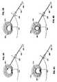
- FIG. 2Ais a plan view of an introducer and an instrument of the invention in which solid lines illustrate the position of the instrument in the absence of bending forces and dotted lines indicate the position the distal portion of the instrument would assume under bending forces applied to the intradiscal section of the instrument, representing an embodiment of the present invention.
- FIG. 2Bis an end view of the handle of the embodiment shown in FIG. 2A .
- FIG. 2Cis an alternative cross-sectional view.
- FIG. 2Dis another alternative cross-sectional view.
- FIG. 3is a side view of a catheter with a elastically deformed end section with an arcuate shape.
- FIGS. 4A-Dshow the surgical steps connected with the insertion of the catheter of FIG. 3 into a surgical site.
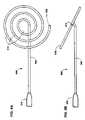
- FIG. 5is a side view of a catheter with a elastically deformed end section with an inward spiral shape.
- FIG. 6A-6Bis a side view of a catheter with a elastically deformed end section with an outward spiral shape.
- FIG. 7is a side view of a catheter with a elastically deformed end section with an “eggbeater” shape.
- FIGS. 8A-Fare isometric views of an alternate embodiment of the invention in which the probe of the catheter performs an electrophoretic function.
- FIGS. 9A-Dshow the surgical steps connected with the insertion of the catheter of FIGS. 7-8 into a surgical site.
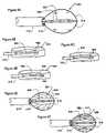
- FIGS. 10A-Bshow catheters with thermal energy delivery sources.
- FIG. 11shows a thermal delivery element for a catheter.
- FIGS. 12A-Cshow a catheter probe with a knife, lumen, and energy delivery element.
- FIG. 13shows a catheter connector including fluid delivery coupling.
- FIG. 14shows another connector with fluid delivery coupling.
- disc abnormalitiessuch as disc degeneration at locations previously not accessible via percutaneous approaches and without major surgical intervention or substantial destruction to the disc. It would be further desirable to treat disc abnormalities via controlled high-energy input available through radio frequency energy. It would be further desirable to provide such RF energy to the nucleus pulposus at the posterior, posterior lateral and the posterior medial regions of the inner wall of the annulus fibrosis, without heating other regions of the nucleus, as would occur with prior art heating elements. It would further be desirable to be able to administer materials to, or remove materials from, a precise, selected location within the disc, particularly to the location of the annular fissure.
- a primary object of the inventionis to provide a minimally invasive method and apparatus for diagnosing and treating fissures of discs at selected locations within the disc.
- Another object of the inventionis to provide a minimally invasive method and apparatus for treating morphological abnormalities of discs at selected locations within the disc via radio frequency electrodes.
- Another object of the inventionis to provide a device which has a distal end that is inserted into the disc and accesses the posterior, posterior lateral and the posterior medial regions of the inner wall of the annulus fibrosis for application of RF energy at such location.
- Another object of the inventionis to provide an apparatus which is advanceable and navigable at the inner wall of the annulus fibrosus to provide localized heating at the site of the annular fissure.
- Another object of the inventioninclude providing apparatus and methods for diagnosing an abnormality and/or adding or removing a material at a preselected location of a disc via a functional element.
- Another object of the inventionis to provide a device which has a distal end that is inserted into the disc and accesses the posterior, posterior lateral and the posterior medial regions of the inner wall of the annulus fibrosus in order to repair or shrink an annular fissure at such a location.
- Another object of the inventionis to provide a non-destructive method and apparatus for treating morphologic abnormalities of discs.
- Another object of the inventionis to provide a method and apparatus to treat degenerative intervertebral discs by delivering thermal energy to denervate selective nerves embedded in the walls of the disc.
- Another objective of the inventionis to provide a method and apparatus to treat degenerative intervertebral discs by delivering thermal energy to cauterize granulation tissue that is ingrown in the wall of the disc.
- Another object of the inventionis to provide a method and apparatus to treat degenerative intervertebral discs by delivering thermal energy to break down selected enzyme systems and neurotransmitters that generate pain within the disc.
- Another object of the inventionis to provide a method and apparatus to treat degenerative intervertebral discs by shrinking a selected amount of collagen in the annulus fibrosis of the disc and remove a redundancy in the disc roll.
- Another object of the inventionis to provide a method and apparatus to treat degenerative intervertebral discs by delivering thermal energy to at least a portion of the nucleus pulposus to reduce water content of the nucleus pulposus and shrink the nucleus pulposus without creating a contained herniated disc.
- Another object of the inventionis to provide a method and apparatus to treat degenerative intervertebral discs by supplying sufficient thermal energy to shrink the nucleus pulposus and tighten the disc.
- Another object of the inventionis to provide an apparatus to treat degenerative intervertebral discs which is advanceable and navigational adjacent to an inner wall of the annulus fibrosis.
- Another object of the inventionis to provide a thermal energy delivery device which has a distal end that is inserted into the nucleus pulposus and accesses the posterior, posterior lateral and the posterior central regions of the inner wall of the nucleus fibrosis.
- the inventionprovides an intervertebral disc apparatus that includes an introducer with an introducer lumen and a catheter.
- the catheteris at least partially positioned in the introducer lumen and includes a probe section and an energy delivery device coupled to the intradiscal section.
- the intradiscal sectionis configured to be advanceable through a nucleus pulposus of the intervertebral disc and positionable adjacent to a selected site of an inner wall of an annulus fibrosis.
- the energy delivery deviceis configured to deliver sufficient energy to heat at least a portion of the intervertebral disc without substantially removing intervertebral disc material positioned adjacent to the energy delivery device.
- the inventionalso includes providing an externally guidable intervertebral disc apparatus for manipulation of disc tissue present at a preselected location of an intervertebral disc, the disc having a nucleus pulposus, an annulus fibrosis, and an inner wall of the annulus fibrosis, the nucleus pulposus having a first diameter and a disc playing between opposing sections of the inner wall, proximity to the nucleus being provided by an introducer comprising an internal introducer lumen with an opening at a terminus of the introducer, comprising a catheter having a distal end and a proximal end having a longitudinal access, the catheter being adapted to slidably advance through the introducer lumen, the catheter having an intradiscal section at the distal end of the catheter, the intradiscal section being extendable through the opening of the introducer and having sufficient rigidity to be advanceable through the nucleus pulposus of the disc and around the inner wall of the annulus fibrosis under a force applied longitudinally to the
- An embodiment of the inventionis based on a catheter for delivering energy to a surgical site.
- the catheterincludes at a proximal end a handle and at a distal end a probe.
- the catheterincludes at least one energy delivery device and an activation element.
- the at least one energy deviceis located at the distal end of the catheter to deliver energy to portions of the surgical site.
- the activation elementis located at the distal end of the catheter, to transition the probe from a linear to a multi-dimensional shape, within the surgical site.
- the catheterincludes a substrate and a heating element.
- the substrateis located at the distal end of the catheter.
- the heating elementis fabricated on the substrate by photo-etching to deliver thermal energy to portions of the surgical site.
- the catheterin another embodiment of the invention includes a first probe section, at least one energy delivery element, a tip and a blade.
- the first probe sectiondefines along a length thereof a first lumen.
- the at least one energy delivery elementis located at the distal end of the catheter to deliver energy to portions of the intervertebral disc.
- the tipis coupled to the first probe section at a terminus thereof.
- the tipdefines on an exterior face a second lumen substantially concentric with said first lumen.
- the bladeis positioned within the first lumen and is extensible from a first position within said first probe section, to a second position extending through the second lumen and beyond the tip, to cut selected portions within the intervertebral disc.
- a catheterin another embodiment, includes an energy delivery element, a material transfer element, and at least one interface on the handle thereof.
- the energy delivery elementis located at the distal end of the catheter to deliver energy to portions of the intervertebral disc.
- the material transfer elementis located at the distal end of the catheter to transfer material to and from the intervertebral disc.
- the at least one interface on the handlecouples the energy delivery element and the material transfer element to external devices for energy and material transfer to and from the intervertebral disc.
- a method for deploying a probe portion of a catheter in a multi-dimensional shape within a surgical siteincludes the steps of: configuring the probe of the catheter in a substantially linear configuration; applying a sufficient force to advance the probe of the catheter through the nucleus pulposus, which force is insufficient to puncture the annulus fibrosus; deploying the probe in a substantially arcuate configuration within the inner wall of the annulus fibrosus, and delivering energy from the probe to portions of the intervertebral disc.
- a catheter for treating an intervertebral discin another embodiment, includes an electrophoretic element located at the distal end of the catheter to alter the milieu within the intervertebral disc.
- the present inventionprovides a method and apparatus for treating intervertebral disc disorders by the application of controlled heating to a localized region of an intervertebral disc.
- Such disordersinclude but are not limited to (i) degenerative discs which have tears or fissures in the annulus fibrosis, particularly fissures of the annulus fibrosis, which may or may not be accompanied with contained or escaped extrusions, (ii) contained disc herniations with focal protrusions, and (iii) bulging discs.
- Electromagnetic energyis delivered to a selected section of the disc in an amount which does not create a destructive lesion to the disc, other than at most a change in the water content of the nucleus pulposus. In one embodiment, there is no removal and/or vaporization of disc material positioned adjacent to an energy delivery device positioned in a nucleus pulposus. Sufficient electromechanical energy is delivered to the disc to change its biochemical, neurophysiologic and/or biomechanical properties. Neurophysiologic modifications include denervation of nociceptores in a tear or fissure in the annulus fibrosis.
- Degenerative intervertebral discs with fissuresare treated by denervating selected nerves that are embedded in the interior wall of the annulus fibrosis as well as nerves outside of the interior wall including those on the surface of the wall. Electromagnetic energy is used to cauterize granulation tissue which are pain sensitive areas and formed in the annulus fibrosis wall. Electromagnetic energy is also used to break down selected enzyme systems and neurotransmitters that generate pain within the disc. Generally, these enzymes and neurotransmitters only work within a small bandwidth of both pH and temperature.
- Electromagnetic energyis applied to shrink collagen in the annulus fibrosis and/or nucleus pulposus. This reduces the redundancy in the disc roll that is created in a degenerative disc. Delivery of electromagnetic energy to the nucleus pulposus removes some water and permits the nucleus pulposus to withdraw. This reduces a “pushing out” effect that created a contained herniation. Combinations of shrinking the disc, shrinking of the nucleus pulposus by reducing water content, as well as tightening up the annulus fibrosis wall creates a rejuvenation of the disc. Reducing the pressure in the disc and tightening the annulus fibrosis produces a favorable biomechanical effect. Application of electromagnetic energy locally increases the stiffness of the disc.
- the annulus fibrosisis comprised primarily of fibrosis-like material and the nucleus pulposus is comprised primarily of an amorphous colloidal gel.
- the distinction between the annulus fibrosis and the nucleus pulposusbecomes more difficult to distinguish when a patient is 30 years old or greater. There is often a transition zone between the annulus fibrosis and the nucleus pulposus made of fibrosis-like material and amorphous colloidal gel.
- the inner wall of the annulus fibrosisincludes the young wall comprised primarily of fibrosis-like material as well as the transition zone which includes both fibrous-like material and amorphous colloidal gels (hereinafter collectively referred to as “inner wall of the annulus fibrosis”).
- an apparatus of the inventionis in the form of an externally guidable intervertebral disc apparatus for accessing and manipulating disc tissue present at a selected location of an intervertebral disc having a nucleus pulposus and an annulus fibrosus, the annulus having an inner wall.
- a temperature-controlled energy delivery elementcombined with the navigational control of the inventive catheter, provides preferential, localized heating to treat the fissure.
- the nucleus pulposuscan be considered as having a given diameter in a disc plane between opposing sections of the inner wall. This nucleus pulposus diameter measurement allows instrument sizes (and parts of instruments) designed for one size disc to be readily converted to sizes suitable for an instrument designed for a different size of disc.
- the operational portion of the apparatus of the inventionis brought to a location in or near the disc's fissure using techniques and apparatuses typical of percutaneous interventions.
- the term “introducer”is used to describe this aid to the method.
- An introducerhas an internal introducer lumen with a distal opening at a terminus of the introducer to allow insertion (and manipulation) of the operational parts of the apparatus into (and in) the interior of a disc.
- the operational part of the apparatuscomprises an elongated element referred to as a catheter, various parts of which are located by reference to a distal end and a proximal end at opposite ends of its longitudinal axis.
- the proximal endis the end closest to the external environment surrounding the body being operated upon (which may still be inside the body in some embodiments if the catheter is attached to a handle insertable into the introducer).
- the distal end of the catheteris intended to be located inside the disc under conditions of use.
- the catheteris not necessarily a traditional medical catheter (i.e., an elongate hollow tube for admission or removal of fluids from an internal body cavity) but is a defined term for the purposes of this specification.
- Catheterhas been selected as the operant word to describe this part of the apparatus, as the inventive apparatus is a long, flexible tube which transmits energy and/or material from a location external to the body to a location internal to the disc being accessed upon, such as a collagen solution and heat to the annular fissure.
- materialcan be transported in the other direction to remove material from the disc, such as removing material by aspiration to decrease pressure which is keeping the fissure open and aggravating the symptoms due to the fissure.
- the catheteris adapted to slidably advance through the introducer lumen, the catheter having an probe section at the distal end of the catheter, the probe section being extendible through the distal opening at the terminus of the introducer into the disc.
- a typical distance of extensionis at least one-half the diameter of the nucleus pulposus, preferably in the range of one-half to one and one-half times the circumference of the nucleus.
- the probe portion of the catheteris manufactured with sufficient rigidity to avoid collapsing upon itself while being advanced through the nucleus pulposus and navigated around the inner wall of the annulus fibrosus.
- the probe portionhas insufficient rigidity to puncture the annulus fibrosus under the same force used to advance the catheter through the nucleus pulposus and around the inner wall of the annulus fibrosus.
- Absolute penetration abilitywill vary with sharpness and stiffness of the tip of the catheter, but in all cases a catheter of the present invention will advance more readily through the nucleus pulposus than through the annulus fibrosus.
- the probe section of the catheterfurther has differential bending ability in two orthogonal directions at right angles to the longitudinal axis. This causes the catheter to bend along a desired plane (instead of at random). Also when a torsional (twisting) force is applied to the proximal end of the catheter to re-orient the distal end of the catheter, controlled advancement of the catheter in the desired plane is possible.
- a further component of the catheteris a functional element located in the probe section for diagnosis or for adding energy and adding and/or removing material at the selected location of the disc where the annular tear is to be treated.
- the apparatusallows the functional element to be controllably guided by manipulation of the proximal end of the catheter into a selected location for localized treatment of the annular fissure.
- the method of the inventionwhich involves manipulating disc tissue at the annular fissure, is easily carried out with an apparatus of the invention.
- An introduceris provided that is located in a patient's body so that its proximal end is external to the body and the distal opening of its lumen is internal to the body and (1) internal to the annulus fibrosus or (2) adjacent to an annular opening leading to the nucleus pulposus, such as an annular tear or trocar puncture that communicates with the nucleus pulposus.
- the catheteris then slid into position in and through the introducer lumen so that the functional element in the catheter is positioned at the selected location of the disc by advancing or retracting the catheter in the introducer lumen and optionally twisting the proximal end of the catheter to precisely navigate the catheter.
- the distal portion of the catheterwill curve along the inner wall of the annulus fibrosus as it is navigated and is selectively guided to an annular tear at selected location(s) in the disc. Energy is applied and/or material is added or removed at the selected location of the disc via the functional element.
- the annulus fibrosusis comprised primarily of tough fibrous material, while the nucleus pulposus is comprised primarily of an amorphous colloidal gel. There is a transition zone between the annulus fibrosus and the nucleus pulposus made of both fibrous-like material and amorphous colloidal gel. The border between the annulus fibrosus and the nucleus pulposus becomes more difficult to distinguish as a patient ages, due to degenerative changes. This process may begin as early as 30 years of age.
- the inner wall of the annulus fibrosuscan include the young wall comprised primarily of fibrous material as well as the transition zone which includes both fibrous material and amorphous colloidal gels (hereafter collectively referred to as the “inner wall of the annulus fibrosus”). Functionally, that location at which there is an increase in resistance to catheter penetration and which is sufficient to cause bending of the distal portion of the catheter into a radius less than that of the internal wall of the annulus fibrosus is considered to be the “inner wall of the annulus fibrosus.”
- stages 1-5degenerative disc disease
- Adams et al.“The Stages of Disc Degeneration as Revealed by Discograms,” J. Bone and Joint Surgery, 68, 36-41 (1986).
- the methods of instrument navigation described hereinwould probably not be able to distinguish between the nucleus and the annulus in degenerative disease of grade 5.
- most treatmentis expected to be performed in discs in stages 3 and 4, as stages 1 and 2 are asymptomatic in most patients, and stage 5 may require disc removal and fusion.
- FIGS. 2A and 2Billustrate one embodiment of a catheter 200 of the invention as it would appear inserted into the lumen 214 of an introducer 210 .
- the apparatus shownis not to scale, as an exemplary apparatus (as will be clear from the device dimensions below) would be relatively longer and thinner; the proportions used in FIG. 2A were selected for easier viewing by the reader.
- the catheter 200includes handle 206 , stem 208 , probe section 216 and a tip 220 .
- the handle 206 at the proximal end of the catheteris coupled via the stem 208 to the probe section 216 , which is located proximate the distal end of the device.
- the tip 220At the terminus of the probe, i.e., the distal end of the device, is the tip 220 .
- the tipmay be axially displaced from the probe section.
- Functional elements 222 for delivery or energy or material to or from the sitemay be placed within the probe. These may, via connections within the probe, stem and handle, be coupled to either an energy delivery device 202 or a material transfer device 204 . Therefore no limitation should be placed on the types of energy, force, or material transporting elements present in the catheter. These are merely some of the possible alternative functional elements that can be included in the probe portion of the catheter.
- the flexible, movable catheter 200is at least partially positionable in the introducer lumen 214 , to bring the probe section, which is designed to be the portion of the catheter that will be pushed out of the introducer lumen and into the nucleus pulposus and into the selected location(s) with regard to the annular tear. Dashed lines are used to illustrate bending of the probe portion of the catheter as it might appear under use, as discussed in detail later in the specification.
- FIG. 2Bshows an axial cross-section of stem 208 at the proximal end of the catheter.
- the stemhas an oval shape, as does the lumen 214 thus allowing the rotational orientation of the probe to be fixed with respect to the introducer.
- Other sections and properties of catheter 200are described later.
- the outer diameter of catheter 200is in the range of 0.2 to 5 mm
- the total length of catheter 200(including the portion inside the introducer) is in the range of 10 to 60 cm
- the length of introducer 210is in the range of 5 to 50 cm.
- the catheterhas a diameter of 1 mm, an overall length of 30 cm, and an introduced length of 15 cm (for the probe section). With an instrument of this size, a physician can insert the catheter for a distance sufficient to reach selected location(s) in the nucleus of a human intervertebral disc.
- Any device in which bending of the tip of a catheter of the invention is at least partially controlled by the physicianis “actively steerable.”
- a mandrelmay facilitate the active steering of a catheter.
- a guiding mandrel 232can be included both to add rigidity to the catheter and to inhibit movement of probe section 216 of the catheter 200 along an inferior axis 242 while allowing it along a superior axis 240 while positioned and aligned in the disc plane of a nucleus pulpous 120 . This aids the functions of preventing undesired contact with a vertebra and facilitating navigation.
- the mandrelcan be flattened to encourage bending in a plane (the “plane of the bend”) orthogonal to the “flat” side of the mandrel. “Flat” here is a relative term, as the mandrel can have a D-shaped cross-section ( FIG.
- the minimum ratiois 1.25:1(“thickest” to “thinnest” cross-sectional dimensions along at least a portion of the probe section).
- the maximum ratiois 20:1, with the preferred ration being between 1.5:1 and 16:3, more preferably between 2:1 and 3.5:1.
- a catheter of the present inventionis designed with sufficient torsional strength (resistance to twisting) to prevent undesired directional movement of the catheter.
- Mandrels formed from materials having tensile strengths in the range set forth in the examples of this specificationprovide a portion of the desired torsional strength. Other materials can be substituted so long as they provide the operational functions described in the examples and desired operating parameters.
- the mandrelcan provide a significant portion of the column strength, selective flexibility, and torsional strength of a catheter
- other structural elements of the catheteralso contribute to these characteristics. Accordingly, it must be kept in mind that it is the characteristics of the overall catheter that determine suitability of a particular catheter for use in the methods of the invention.
- components inside the cathetersuch as a heating element or potting compound, can be used to strengthen the catheter or provide directional flexibility at the locations of these elements along the catheter.
- the guiding mandrel 232be flattened along its entire length. Different mandrels can be designed for different sized discs, both because of variations in disc sizes from individual to individual and because of variations in size from disc to disc in one patient.
- the bendable portion of the mandrelis preferably sufficient to allow probe section 216 of the catheter to navigate at least partially around the circumference of the inner wall of the annulus fibrosus (so that the operational functions of the catheter can be carried out at desired location(s) along the inner wall of the annulus fibrosus). Shorter bendable sections are acceptable for specialized instruments. In most cases, a flattened distal portion of the mandrel of at least 10 mm, preferably 25 mm, is satisfactory. The flattened portion can extend as much as the entire length of the mandrel, with some embodiments being flattened for less than 15 cm, in other cases for less than 10 cm, of the distal end of the guide mandrel.
- the guide mandrel or other differential bending control elementis maintained in a readily determinable orientation by a control element located at the proximal end of the catheter.
- the orientation of the direction of bending and its amountcan be readily observed and controlled by the physician.
- One possible control elementis simply a portion of the mandrel that extends out of the proximal end of the introducer and can be grasped by the physician, with a shape being provided that enables the physician to determine the orientation of the distal portion by orientation of the portion in the hand.
- a flattened shapecan be provided that mimics the shape at the distal end (optionally made larger to allow better control in the gloved hand of the physician, as in the handle 206 of FIG. 2A ).
- More complex proximal control elementscapable of grasping the proximal end of the mandrel or other bending control element can be used if desired, including but not limited to electronic, mechanical, and hydraulic controls for actuation by the physician.
- the guide mandrelcan also provide the function of differential flexibility by varying the thickness in one or more dimensions (for example, the “thin” dimension, the “thick” dimension, or both) along the length of the mandrel.
- a guide mandrel that tapers (becomes gradually thinner) toward the distal tip of the mandrelwill be more flexible and easier to bend at the tip than it is at other locations along the mandrel.
- a guide mandrel that has a thicker or more rounded tip than more proximal portions of the mandrelwill resist bending at the tip but aid bending at more proximal locations. Thickening (or thinning) can also occur in other locations along the mandrel.
- Control of the direction of bendingcan be accomplished by making the mandrel more round, i.e., closer to having 1:1 diameter ratios; flatter in different sections of the mandrel; or by varying the absolute dimensions (increasing or decreasing the diameter).
- Such control over flexibilityallows instruments to be designed that minimize bending in some desired locations (such as the location of a connector of an electrical element to avoid disruption of the connection) while encouraging bending in other locations (e.g., between sensitive functional elements).
- a catheter that is uniformly flexible along its entire lengthis variably flexible along its entire length, or has alternating more flexible and less flexible segment(s), is readily obtained simply by manufacturing the guide mandrel with appropriate thickness at different distances and in different orientations along the length of the mandrel.
- Such a catheterwill have two or more different radii of curvature in different segments of the catheter under the same bending force.
- the most distal 3 to 40 mm of a guide mandrelis thinner relative to central portions of the probe section to provide greater flexibility, with the proximal 10 to 40 mm of the probe section being thicker and less flexible to add column strength and facilitate navigation.
- the actual dimensions of the guide mandrelwill vary with the stiffness and tensile strength of the material used to form the mandrel.
- the mandrelwill be formed from a metal (elemental or an alloy) or plastic that will be selected so that the resulting catheter will have characteristics of stiffness and bending that fall within the stated limits. Additional examples of ways to vary the stiffness and tensile strength include transverse breaks in a material, advance of the material so that it “doubles up,” additional layers of the same or different material, tensioning or relaxing tension on the catheter, and applying electricity to a memory metal.
- Catheters which are actively steerablemay include additionally the capability of deploying into planar substantially two dimensional shapes or three dimensional shapes which conform to the surgical site. These multi-dimensional deployment capabilities, reduce operating time, improve operational accuracy and increase the utility of surgical intervention.
- FIGS. 3-9show apparatus and methods for transitioning a probe from a linear to a multi-dimensional shape.
- the transition of the probe from a linear to an arcuate shapemay be brought about by any of a group of activation elements including, but not limited to, the following.
- the probemay include a resilient material, e.g. a heat treated metal or spring metal, which will assume a linear shape only by virtue of the guiding force of the lumen portion of the introducer and will resume its original arcuate shape, upon introduction to the surgical site and by extension beyond the confines of the introducer.
- the resilient spring-like materialis arcuate in the absence of external stress but, under selected stress conditions (for example, while the catheter is inside the introducer), is linear.
- Such a biased distal portioncan be manufactured from either spring metal or superelastic memory material (such as Tinel® nickel-titanium alloy, Raychem Corp., Menlo Park Calif.).
- the introducer(at least in the case of a spring-like material for forming the catheter) is sufficiently strong to resist the bending action of the bent tip and maintain the biased distal portion in alignment as it passes through the introducer.
- a catheter with a biased probeencourages advancement of the probe substantially in the direction of the bend relative to other lateral directions. Biasing the catheter tip also further decreases likelihood that the tip will be forced through the annulus fibrosus under the pressure used to advance the catheter.
- an introducer in combination with the resilient materialis necessary in order to introduce the probe in a linear or lay flat configuration to the surgical site.
- an introducermay also be used with any of the following activation elements it is not necessary to bring about the transition from a linear to an arcuate shape.
- the probemay include at least two materials with a different coefficient of thermal expansion joined to one another along their length, such that at one temperature, e.g., room temperature they are linear while at an elevated temperature, the differential expansion of one with respect to the other induces an arcuate bending of both.
- Bi-metallic stripssuch as copper and steel might serve this function. Any other two metals with different coefficients of expansion could be substituted for copper and steel. The greater the differential of the coefficients of expansion between the two metals the smaller the radius(s) of the arcuate shape formed thereby at any given temperature differential.
- Other materials besides metals with different coefficients of expansioncould also be used.
- the temperature differential of the at least two materials at room temperature and at the surgical sitemay be increased by energy delivered to the probe, e.g., RF or resistive heating.
- energy delivered to the probee.g., RF or resistive heating.
- electrical powermay be applied directly to one or both of the at least two materials provided they are electrically resistive such that the application of power will result in heat generation.
- the arcuate shapemay be brought about by use of materials with temperature dependent shape memory such as the metal alloy Nitinol.
- the probeis fabricated to be linear at room temperature and arcuate at the temperature of the surgical site.
- the temperature differential of the Nitenol at room temperature and at the surgical sitemay be increased by energy delivered to the probe, e.g. RF or resistive heating.
- the electrical powermay be directly applied directly to the Nitenol which is itself a resistive element.
- the arcuate shapemay be induced using electrical activated expansion and contraction of materials within the probe.
- Piezoelectric crystals positioned on either the exterior or interior radius of the arcmay be used in this manner to respectively expand or contract against a surface of a mandrel within the probe, to induce an arcuate shape.
- the alteration of shape from linear to arcuatemay be produced by mechanical means such as the combination of a draw wire and mandrel, coupled at the tip of the device and extending the length of the catheter, such that tension of the draw wire induces tension on a side of the mandrel inducing it to assume an arcuate shape.
- mechanical meanssuch as the combination of a draw wire and mandrel, coupled at the tip of the device and extending the length of the catheter, such that tension of the draw wire induces tension on a side of the mandrel inducing it to assume an arcuate shape.
- Numerous combinations of material and energy, either thermal or electricalcan be used to create a deformable tip.
- An advantageous feature of all the probes set forth in the current inventionis that their shape can be configured to conform to the interior shape of the surgical site to which they are introduced, thus placing functional elements on the probe into proximity with all portions of the surgical site without the need for a point-by-point navigation of the probe tip about the surgical site.
- FIG. 3shows an embodiment of a surgical catheter with a shape shifting probe portion portion.
- the catheter 300includes handle 306 , stem 308 , probe section 316 , and tip 320 .
- the handle 306 at the proximal end of the catheteris coupled via the stem 308 to the probe section 316 , which is located proximate the distal end of the device.
- the tip 320At the terminus of the probe, i.e., the distal end of the device, is the tip 320 .
- the probeis fabricated from a resilient material thus requiring an introducer to effect its transition from a linear to an arcuate shape.
- any of the other activation elements described abovecould be utilized to effect a transition of the probe section from a linear to a multi-dimensional shape.
- FIGS. 4A-Dshow the sequence of operations associated with the insertion of the probe section 316 of the catheter 300 shown in FIG. 3 into the nucleus pulposus 120 of a spinal disc.
- the terminus of lumen 214(See FIG. 2A ) has been introduced into the nucleus pulposus of the disc substantially tangent to the interior sidewall of the disc.
- FIG. 4Bhandle and stem, respectively, 306 - 308 of the catheter are inserted further into the introducer 210 so that the tip 320 of the probe section begins to extrude into the intradiscal space.
- the insertioncontinues with the probe section 316 positioned to reside along at least about a half-circumference of the intervertebral disc and continues until the probe section 316 has formed a complete circle, with the tip 320 adjacent to the lumen 214 of the introducer 210 .
- the plane defined by the arcuate probeis coplanar with the intradiscal plane defined by the intervertebral disc.
- the functional elementmay include a lumen for the introduction and/or removal of material into the surgical site.
- the probe tipmay include a surgical knife, either alone or in combination with a lumen. (See FIGS. 12A-C ).
- a radiographically opaque marking devicecan be included in the distal portion of the catheter (such as in the tip or at spaced locations throughout the probe portion) so that advancement and positioning of the probe section can be directly observed by radiographic imaging. Such radiographically opaque markings are preferred when the probe section is not clearly visible by radiographic imaging, such as when the majority of the catheter is made of plastic instead of metal.
- a radiographically opaque markingcan be any of the known (or newly discovered) materials or devices with significant opacity.
- Examplesinclude but are not limited to a steel mandrel sufficiently thick to be visible on fluoroscopy, a tantalum/polyurethane tip, a gold-plated tip, bands of platinum, stainless steel or gold, soldered spots of gold and polymeric materials with radiographically opaque filler such as barium sulfate.
- a resistive heating element or an RF electrode(s)may provide sufficient radio-opacity in some embodiments to serve as a marking device.
- FIG. 5shows an alternate embodiment of the catheter with an inward spiraling probe portion.
- the catheter 500has a handle 306 coupled via stem 308 to the spiral probe section 516 .
- the spiral probe sectionterminates at the distal end of the catheter in a tip 520 .
- the cathetermay be caused to attain a spiral shape by numerous activation elements including the use of materials which are: resilient or bi-metallic, which exhibit temperature dependent shape memory, by materials in which electrical expansion and contraction may be induced, and by mechanical means.
- materialswhich are: resilient or bi-metallic, which exhibit temperature dependent shape memory, by materials in which electrical expansion and contraction may be induced, and by mechanical means.
- a possible advantage of the inward spiraling shapeis that material may be swept during deployment of the probe radially inward/outward.
- FIG. 6A-Bshow respectively elevation and side views of an alternate embodiment of a catheter with a catheter 600 with an outward spiraling probe.
- Probe section 616is coupled via stem 308 to handle 306 .
- Tip 620is at the terminus of the Probe 616 at the distal end of the catheter 600 .
- the stem 308intersects at an acute angle the plane defined by the spiral probe section 616 . Such alteration of the plane of the probe with respect to the stem may result in improved conformity of the probe with the intradiscal cavity or other joint into which the probe may be introduced.
- the cathetermay be caused to attain a spiral shape by numerous activation elements including the use of materials which are: resilient or bi-metallic, which exhibit temperature dependent shape memory, by materials in which electrical expansion and contraction may be induced, and by mechanical means.
- materialswhich are: resilient or bi-metallic, which exhibit temperature dependent shape memory, by materials in which electrical expansion and contraction may be induced, and by mechanical means.
- a possible advantage of the outward spiraling shapeis that material may be swept during deployment of the probe radially inward/outward.
- the catheter 700 shown in FIG. 7-8may be fabricated to deploy into either a planar two dimensional shape or into a three dimensional “eggbeater” shape which conforms to the surgical site.
- the catheterincludes a handle 706 , a stem 708 , a probe 702 and an introducer 210 .
- the handle 706includes a push/pull member 704 .
- the stem 708includes a draw member 730 .
- the introducer 210includes an internal lumen 214 .
- the probe 702includes side members 716 and a core member 732 .
- One or more of the side members 716are arranged radially about core member 732 .
- the coreextends axially and is attached at a distal end of the probe 702 to the distal ends of the side members by tip 720 .
- the corejoins with the draw member 730 as an axial extension thereof.
- the proximal ends of the side members 716are slidably affixed to the draw member. Axially induced movement of the proximal ends of the side members along that draw member and toward the core member 732 results in an arcuate deflection of the side members from a collapsed position adjacent to the axial core to an expanded position radially displaced about the axial core.
- the draw member 730extends axially the full length of the stem 708 and of the handle 706 to a point of attachment at the push/pull member 704 of the handle.
- the draw memberis slidable axially within the stem.
- the push/pull member 704 of the handle 706is slidable axially with respect to the handle 706 .
- the side members 716are brought into a lay-flat condition against the axial core prior to introduction into the introducer. This situation is brought about by the positioning of push-pull member adjacent to the handle 706 . This causes the maximal extension of the draw member from a distal end of the stem 708 .
- the lay-flat membersare tension springs, which in the relaxed position lay flat against the axial core. In this linear configuration, the tip 720 of the probe is placed into the introducer 210 . When the probe 702 is extended beyond the introducer and into the surgical site, the draw member is gradually retracted into the handle by a displacement of the push-pull member 704 away from the base portion of the handle 706 .
- the side members in a relaxed positionassume an arcuate shape radially displaced about the axial core.
- the cathetermay be caused to attain the “eggbeater” or other shapes by numerous activation elements including the use of materials which are: resilient or bi-metallic, which exhibit temperature dependent shape memory, by materials in which electrical expansion and contraction may be induced, and by mechanical means.
- Electrophoresiscan be defined as the movement of charged particles or substances through a medium in which they are dispersed as a result of changes in electrical potential.
- electrophoretic methodsare useful in separating various molecular particles depending upon the size and shape of the particle, the charge carried, the applied current and the resistance of the medium.
- the chemical milieu of a surgical sitee.g., the nucleus pulposus, can be altered by electrophoretic methods, with beneficial therapeutic effects such as pain reduction or intradiscal repair.
- ions or free radicalsmay be found in high concentrations in chronically inflamed states of surgical sites such as the intradiscal cavity of the spine.
- Disco-genic painmay for example be associated with higher than normal concentrations of enzymes such as phospholipase A-2 in the spinal disc wall, or the nucleus pulposus for example.
- enzymessuch as phospholipase A-2 in the spinal disc wall, or the nucleus pulposus for example.
- a recently discovered short proteinbinds to cell membranes in the brain and spinal cord and may be affected and controlled by electrophoretic methods. The peptide, nocistatin, seemed to block pain or the transmission of pain to the nociceptors or pain receptors when injected into animals.
- Nocistatinappears to interact with the peptide nociceptin in a manner which may either amplify or reduce pain depending on the relative concentrations of the two peptides. Control of the these two peptides by electrophoresis may prove beneficial in the treatment of back pain.
- a probeBy inserting a probe into the site with a functional element capable of performing an electrophoretic function, it may be possible to reduce the concentrations of the charged particles: e.g. enzymes, neurotransmitters, proteins, individual molecules, or free radicals to achieve one or more beneficial therapeutic effects including but not limited to pain reduction, intradiscal reshaping or repair.
- a functional elementcapable of performing an electrophoretic function
- the concentrationsmay be reduced by migration of the charged particles from perimeter regions of the surgical site toward the core of the site, by means of an appropriately configured probe, with electrodes positioned at the perimeter and core of the surgical site, which electrodes are charged in a manner designed to encourage whichever of a radially outward or inward migration of the charged particles is therapeutically beneficial.
- FIGS. 8A-Fshow multi-dimensional probes with side and core members deployed into a multi-dimensional configuration at the surgical site.
- the side and core membersmay perform an electrophoretic function by means of electrical stimulus of opposite polarity applied to each.
- the electrical stimulusmay be pure DC or rectified AC at frequencies including the radio frequency range.
- side members 816naturally assume an arcuate configuration radially displaced about core 832 . They may be compressed against the core as is the case when they are within the lumen 214 within the introducer 210 . As they collectively extended through the lumen and into the surgical site their internal spring tension causes them to assume an arcuate configuration radially displaced about the core. At the completion of the surgery they may be withdrawn into the lumen, and in so doing, collapse against the core.
- central core 832provides structural support to the tip of the probe. Additionally, central core 832 is surrounded by membrane 833 which serves as a central collector region for the electrophoresis. In another embodiment of the invention the membrane 833 may itself serve as an electrode.
- the cathetermay be caused to attain the “eggbeater” or other shapes by numerous activation elements including the use of materials which are: resilient or bimetallic, which exhibit temperature dependent shape memory, by materials in which electrical expansion and contraction may be induced, and by mechanical means.
- the side members 816 and core 832may perform as electrodes.
- the side members and core memberare coupled to electrical power to serve as respectively either anodes-cathode or cathodes-anode to one another.
- the electrical connectionscouple the electrodes to a source of power which may be located in the catheter or be externally coupled to the electrodes through a coupling on the handle of the catheter. (See FIGS. 13-14 ). This arrangement may have certain surgical benefits.
- the coreBy allowing the side members and core to serve as respectively perimeter and core electrodes the core can be charged providing an electrical gradient for electrophoresis to pull charged particles from a perimeter region in the disc to the core.
- the charge of the core 832 electrodemay be continuously maintained during collapse of the side members and retraction of the probe from the surgical site, to remove the charged particles from the surgical site, e.g. the nucleus pulposus. This would effect a change to the nucleus pulposus and reduce the electrical potential on the nociceptors, i.e. pain receptors, thereby reducing pain perception as well as removing material from the disc.
- electrically charged particlesmay be introduced into the intradiscal cavity by means of membrane 833 .
- membrane 833Upon deployment of the side members at the surgical site, and appropriate charging of the side and perimeter members the charged particles may be encouraged to migrate toward the side members thereby affecting a change of the chemical milieu of the site.
- FIGS. 8B-Dshows demonstratively alternate functional embodiments of the probe 820 deployed in relation to the intradiscal cavity which contains the nucleus pulposus 120 .
- FIG. 8Bshows one functional embodiment of the invention where side structural members serve as a cathode 826 while central core serves as an anode 842 . Under application of direct current, the negatively charged particles are drawn toward anode 842 .
- FIG. 8Cshows probe 820 where side structural members serve as anode 842 while the core serves as cathode 826 .
- FIG. 8Dshows another embodiment where the core 832 is not an electrode and side structural members serve as individual electrodes. Side structural members are each charged differently with one structural member serving as anode 842 and the other side structural member serving as cathode 826 .
- FIG. 8Eshows an alternative embodiment of the functional aspect of probe 820 with additional intermediate side members 835 .
- Intermediate side members 835are, in a deployed state, located radially between the core and an associated one of the side members.
- Intermediate side members 835are each electrically coupled to a corresponding one of side members 816 by means of electrical connectors/ribs 825 .
- the ribscreate a greater electrical potential by increasing the electrode region.
- the individual ribs 825may be constructed of the same material as intermediate side members 835 or any other electrically conductive material.
- the “fishrib” or fan-shaped structure of probe 820 in this embodimentcreates a greater driving force for changing the chemical milieu of the intradiscal cavity by electrophoretic means.
- FIG. 8Fis an embodiment whereby the greater electrical potential is created by increasing the surface area of the electrode region by use of a film 822 with an electrically conductive layer, e.g. vacuum metalized polyester.
- the conductive layermay be continuous or patterned.
- Opposing sides of the filmare affixed to respective ones of intermediate side members 837 and side members 816 .
- As the tip is deployed and expands to form an arcuate shape the filmis deployed to expose the electrically conductive layer.
- the electrical gradient createdis similar to FIG. 8E where a greater driving force pushes the negatively charged particles towards the central anode.
- the electrophoretic probemay be implemented utilizing a probe which, unlike the probes disclosed above, is substantially linear in shape.
- electrophoretic functionalityis achieved by axially displaced electrodes on the probe which are energized to opposing polarity to effect a migration of charged particles from one electrode to the other, to achieve a beneficial therapeutic effect.
- FIGS. 9A-Dshow the insertion stages of the catheter at a surgical joint, in this case the intervertebral disc and specifically the nucleus pulposus 120 thereof.
- the device being insertedis the catheter 700 shown in FIG. 7 .
- FIG. 9Ashows the introducer 210 positioned so that the lumen at its distal end is within the intradiscal cavity.
- the stem 708connects the handle 706 to the probe 702 .
- the push-pull member 704 of the handle 706is in the inserted position proximate to the handle. In that position the draw member 730 (not shown) is fully extended and the collapsible side members 716 lay flat against the axial core member 732 within the intradiscal cavity.
- FIGS. 9B-Dshow various stages of the expansion of collapsible side members 716 radially about axial core member 732 . This deployment is brought about by the retraction of the draw member 730 (not shown) through stem 708 by means of the displacement of the push-pull member 704 away from the handle 706 .
- a purpose of the inventive catheteris to repair tears or fissures in a disc by operation of the instrument at the tear location adjacent to or inside the disc, a functional element is provided in or on the catheter to carry out that purpose.
- Non-limiting examples of functional elementsinclude any element capable of aiding diagnosis, delivering energy, or delivering or removing a material from a location adjacent the element's location in the catheter, such as an opening in the catheter for delivery of a fluid (e.g., dissolved collagen to seal the fissure) or for suction, a thermal energy delivery device (heat source), a mechanical grasping tool for removing or depositing a solid, a cutting tool (which includes all similar operations, such as puncturing), a sensor for measurement of a function (such as electrical resistance, temperature, or mechanical strength), or a functional element having a combination of these functions.
- a fluide.g., dissolved collagen to seal the fissure
- a thermal energy delivery deviceheat source
- a mechanical grasping toolfor removing or depositing a solid
- a cutting toolwhich includes all similar operations, such as puncturing
- a sensor for measurement of a functionsuch as electrical resistance, temperature, or mechanical strength
- the functional elementcan be at varied locations in the probe portion of the catheter, depending on its intended use. Multiple functional elements can be present, such as multiple functional elements of different types (e.g., a heat source and a temperature sensor) or multiple functional elements of the same type (e.g., multiple heat sources spaced along the probe portion).
- multiple functional elements of different typese.g., a heat source and a temperature sensor
- multiple functional elements of the same typee.g., multiple heat sources spaced along the probe portion.
- thermal energy delivery deviceOne of the possible functional elements present on probe section 216 is a thermal energy delivery device.
- thermal energy delivery deviceis positioned proximal to the distal portion of probe section 216 so that there is no substantial delivery of energy at the distal portion, which can then perform other functions without being constrained by being required to provide energy (or resist the resulting heat).
- the energy directing deviceis configured to limit thermal and/or electromagnetic energy delivery to a selected site of the disc and to leave other sections of the disc substantially unaffected.
- the energycan be directed to the walls of the fissure to cauterize granulation tissue and to shrink the collagen component of the annulus, while the nucleus is shielded from excess heat.
- catheter probe section 216 and/or tip 220are positionable to selected site(s) around and/or adjacent to inner wall of an annulus fibrosus for the delivery of therapeutic and/or diagnostic agents including but not limited to, electromagnetic energy, electrolytic solutions, contrast media, pharmaceutical agents, disinfectants, collagens, cements, chemonucleolytic agents, and thermal energy.
- Probe section 216is navigational and can reach the posterior, the posterior lateral, the posterior medial, anterior lateral, and anterior medial regions of the annulus fibrosus, as well as selected section(s) on or adjacent to the inner wall of the nucleus pulposus 120 .
- FIGS. 10A-B , 11 , and 12 A-Cembodiments of the catheter are shown in which the probe delivers thermal energy to reduce pain without ablation or removal of any disc material adjacent to and with or without removal of water vapor from the disc but without charring the nucleus.
- the probe sectionalso can heat the collagen components of the annulus, thereby shrinking the annulus, with or without desiccating local tissue.
- FIGS. 10A-Bshow alternate embodiments of a probe and tip, which include functional elements with the capability of delivering energy to the surgical site.
- the functional elementsexhibits combined resistive and radio frequency energy delivery capability.
- the deviceincludes dual resistive heating capability.
- FIG. 10Athe distal portion of a probe 1000 is shown.
- the probeis tubular with an interior wall 1006 .
- a tip 1002is affixed to the probe.
- Within the interior of the probea resistive heating coil 1012 is positioned.
- the resistive heating coilis coupled via wires 1014 extending through the stem and handle to an energy delivery device 202 (see FIG. 2A ).
- the probeitself is electrically conductive, thus allowing for the delivery of R.F. power to tip 1002 at the terminus of the probe 1000 .
- the tipin combination with a return pad (not shown) affixed to the patient, provides monopolar R.F. delivery to the surgical site. To prevent R.F.
- an outer sheath 1004which is electrically insulating, is provided to surround all except the terminus of probe 1000 .
- a temperature sensing device 1018is positioned inside the tip. That device is coupled via wires 1020 which extend the length of the stem to the handle to external controls for monitoring energy to the surgical site.
- Heating coil 1012may be powered by a direct current source (and less preferably a source of alternating current).
- Heating coil 1012is made of a material that acts as a resistor. Suitable materials include but are not limited to stainless steel, nickel/chrome alloys, platinum, and the like.
- the heating elementis inside the probe.
- the resistive materialis electrically insulated and substantially no current escapes into the body. With increasing levels of current, the coils heat to greater temperature levels. In one embodiment, 2 watts pass through heating element 46 to produce a temperature of about 55° C. in a selected target such as fissure, 3 watts produces 65° C., 4 watts produces 75° C., and so on.
- FIG. 10Bshows an alternate embodiment of the energy delivery element.
- dual resistive/radio-frequency heat deliveryis provided.
- the probe 1050defines an interior lumen portion in which tip 1052 is placed.
- Short and long heating elements, respectively 1062 - 1068are positioned around the exterior of the probe, and are electrically connected using wires (not shown) to energy delivery device 202 (see FIG. 2A ).
- thermo-couples 1070 and 1072are provided to monitor the temperature of each of the coils.
- radio frequency energyis delivered to the heating elements.
- coils 1062 , 1068are positioned on the exterior of probe 1050 and serve as RF electrodes powered by an RF generator.
- the electrodesare made of suitable materials including but not limited to stainless steel or platinum. Increasing levels of current conducted into disc tissue heat that tissue to greater temperature levels.
- a circuitcan be completed substantially entirely at probe section 16 (bipolar device) or by use of a second electrode attached to another portion of the patient's body (monopolar device). In either case, a controllable delivery of RF energy is achieved.
- sufficient energyis delivered to the intervertebral disc to heat and shrink the collagen component of the annulus but not ablate tissue adjacent to catheter 14 .
- the amount of thermal energy delivered to the tissueis a function of (i) the amount of current passing through the heating element, (ii) the length, shape, and/or size of the heating element, (iii) the resistive properties of the heating element, (iv) the gauge of the heating element, and (v) the use of cooling fluid to control temperature. All of these factors can be varied individually or in combination to provide the desired level of heat.
- Energy delivery device 202 associated with the heating elementmay be battery based.
- the catheterscan be sterilized and may be disposable.
- FIG. 11shows an alternate embodiment for the construction of resistive heating coils.
- a thin film resistive elementgenerally 1100 , fabricated using technology derived from printed circuit boards, is provided.
- the resistive wire 1106is fabricated as part of a substrate or film 1108 , using photo-etch/engraving techniques.
- the substratemight for example be a polyester film.
- the wiremay be internal to or deposited on a surface of the substrate.
- the coilcan be fabricated on one side only of the substrate of film 1108 , thus allowing for asymmetric delivery of heat.
- the corecan be positioned in the interior of the probe or heat shrunk around the exterior of the probe.
- FIGS. 12A-Cshow an alternate embodiment of the invention in which a number of functional elements are provided including a retractable blade, a lumen and a resistive heating element.
- FIG. 12Ashows an exterior side view of probe 1200 .
- FIG. 12Bshows a cross-sectional side view of the probe 1200 .
- FIG. 12Cshows a cross-sectional axial view from the probe interior facing the tip end of the probe.
- FIG. 12Ashows the probe 1200 , generally tubular in shape, with an exterior tubular portion 1202 .
- a tip 1204is affixed.
- the tipdefines in its face, a lumen opening 1206 in which the cutting tip of a retractable blade 1208 is shown in the retracted position.
- the exterior dimensions of the retractable bladeare sufficiently less than the interior dimensions of the lumen 1206 so as to allow for not only the retraction and extension of the blade, but also for either the removal by suction or introduction by pressure of material from or to the surgical site.
- FIG. 12Bshows the cross-sectional view of the probe shown in FIG. 12A .
- the deviceis seen to include resistive heating coils 1210 contained within a spacing between the exterior tubular portion 1202 and an interior tubular portion 1212 of the probe 1200 .
- the retractable bladeis in turn slidably positioned within the interior tubular portion.
- FIG. 12Cshows a cross-sectional view facing toward the end of probe 1200 .
- the exterior tubular portion 1202 and the interior tubular portion 1212 of the probe 1200are shown. In the spacing between them the resistive heating coils 1210 are shown.
- the blade 1208is axially positioned within the inner tubular wall 1212 .
- the lumen 1206may be configured to transport a variety of different mediums including but not limited to electrolytic solutions (such as normal saline), contrast media (such as Conray meglumine iothalamate), pharmaceutical agents, disinfectants, filling or binding materials such as collagens or cements, chemonucleolytic agents and the like, from the material delivery/removal device 204 (see FIG. 2A ) to a desired location within the interior of a disc (i.e., the fissure). Further, the lumen can be used to remove nucleus material or excess liquid or gas (naturally present, present as the result of a liquefying operation, or present because of prior introduction) from the interior of a disc.
- electrolytic solutionssuch as normal saline
- contrast mediasuch as Conray meglumine iothalamate
- pharmaceutical agentssuch as disinfectants, filling or binding materials such as collagens or cements, chemonucleolytic agents and the like
- the lumencan be used to remove nucleus material or excess
- the lumenWhen used to transport a fluid for irrigation of the location within the disc where some action is taking place (such as ablation, which generates waste materials), the lumen is sometimes referred to as an irrigation lumen.
- the lumencan be coupled to the material delivery/removal device 204 through the catheter.
- other instrumentscan be delivered through the lumen including but not limited to: graspers, drill and biopsy needle.
- FIG. 13shows a split interface generally 1300 for providing connections on the handle of the catheter to join energy delivery and material transfer elements within the probe 216 (See FIG. 2A ) of the catheter to material delivery/removal device 204 and energy delivery device 202 (see FIG. 2A ).
- An electrical interface 1302a luer interface 1306 for fluids and an auxiliary interface 1304 are shown.
- the auxiliary interfacecould be utilized for a needle syringe, graspers or an optical fiber for viewing a surgical site.
- the probemay be configured for any one or all of these functional elements.
- FIG. 14shows an integrated interface 1400 for providing connections on the handle of the catheter to join energy delivery and material transfer elements within the probe 216 (See FIG. 2A ) of the catheter to material delivery/removal device 204 and energy delivery device 202 (see FIG. 2A ).
- Electrical interfaces generally 1402 and a luer interface 1404 for the introduction or removal of material to the surgical siteare shown.
- External threads 1406are shown for coupling the interface to material and energy delivery devices.
- the individual componentsneed not be formed in the disclosed shapes, or assembled in the disclosed configuration, but could be provided in virtually any shape, and assembled in virtually any configuration. Further, the individual components need not be fabricated from the disclosed materials, but could be fabricated from virtually any suitable materials. Furthermore, all the disclosed elements and features of each disclosed embodiment can be combined with, or substituted for, the disclosed elements and features of every other disclosed embodiment except where such elements or features are mutually exclusive.
Landscapes
- Health & Medical Sciences (AREA)
- Life Sciences & Earth Sciences (AREA)
- Surgery (AREA)
- Engineering & Computer Science (AREA)
- Public Health (AREA)
- Animal Behavior & Ethology (AREA)
- Nuclear Medicine, Radiotherapy & Molecular Imaging (AREA)
- Veterinary Medicine (AREA)
- Biomedical Technology (AREA)
- General Health & Medical Sciences (AREA)
- Medical Informatics (AREA)
- Heart & Thoracic Surgery (AREA)
- Molecular Biology (AREA)
- Otolaryngology (AREA)
- Physics & Mathematics (AREA)
- Plasma & Fusion (AREA)
- Orthopedic Medicine & Surgery (AREA)
- Radiology & Medical Imaging (AREA)
- Dentistry (AREA)
- Cardiology (AREA)
- Oral & Maxillofacial Surgery (AREA)
- Neurology (AREA)
- Neurosurgery (AREA)
- Surgical Instruments (AREA)
- Prostheses (AREA)
- Materials For Medical Uses (AREA)
- Radiation-Therapy Devices (AREA)
- Electrotherapy Devices (AREA)
Abstract
Description
Claims (18)
Priority Applications (21)
| Application Number | Priority Date | Filing Date | Title |
|---|---|---|---|
| US08/881,692US6073051A (en) | 1996-08-13 | 1997-06-24 | Apparatus for treating intervertebal discs with electromagnetic energy |
| US08/881,527US5980504A (en) | 1996-08-13 | 1997-06-24 | Method for manipulating tissue of an intervertebral disc |
| US08/881,694US6095149A (en) | 1996-08-13 | 1997-06-24 | Method for treating intervertebral disc degeneration |
| US08/881,693US6007570A (en) | 1996-08-13 | 1997-06-24 | Apparatus with functional element for performing function upon intervertebral discs |
| US08/881,525US6122549A (en) | 1996-08-13 | 1997-06-24 | Apparatus for treating intervertebral discs with resistive energy |
| US09/153,552US6126682A (en) | 1996-08-13 | 1998-09-15 | Method for treating annular fissures in intervertebral discs |
| US09/162,704US6099514A (en) | 1996-08-13 | 1998-09-29 | Method and apparatus for delivering or removing material from the interior of an intervertebral disc |
| US09/236,816US6290715B1 (en) | 1996-08-13 | 1999-01-25 | Method for delivering energy adjacent the inner wall of an intervertebral disc |
| US09/363,894US6261311B1 (en) | 1996-08-13 | 1999-07-30 | Method and apparatus for treating intervertebral discs |
| US09/706,244US6517568B1 (en) | 1996-08-13 | 2000-11-03 | Method and apparatus for treating intervertebral discs |
| US09/707,627US6547810B1 (en) | 1996-08-13 | 2000-11-06 | Method for treating intervertebral discs |
| US10/388,609US6997941B2 (en) | 1996-08-13 | 2003-03-17 | Method and apparatus for treating annular fissures in intervertebral discs |
| US10/712,006US7400930B2 (en) | 1996-08-13 | 2003-11-14 | Method for treating intervertebral discs |
| US10/712,063US7267683B2 (en) | 1996-08-13 | 2003-11-14 | Method for treating intervertebral discs |
| US10/712,007US7282061B2 (en) | 1996-08-13 | 2003-11-14 | Method of treating intervertebral disc |
| US10/898,671US7309336B2 (en) | 1996-10-23 | 2004-07-26 | Catheter for delivery of energy to a surgical site |
| US11/872,470US8187312B2 (en) | 1996-08-13 | 2007-10-15 | Method for treating intervertebral disc |
| US11/929,644US8128619B2 (en) | 1996-08-13 | 2007-10-30 | Method for treating intervertebral discs |
| US11/930,783US8082043B2 (en) | 1996-08-13 | 2007-10-31 | Method for treating intervertebral disc degeneration |
| US11/930,731US7896909B2 (en) | 1996-08-13 | 2007-10-31 | Method for treating intervertebral discs |
| US11/931,057US20080058707A1 (en) | 1996-10-23 | 2007-10-31 | Catheter for delivery of energy to a surgical site |
Applications Claiming Priority (20)
| Application Number | Priority Date | Filing Date | Title |
|---|---|---|---|
| US2973496P | 1996-10-23 | 1996-10-23 | |
| US2960296P | 1996-10-23 | 1996-10-23 | |
| US2973596P | 1996-10-23 | 1996-10-23 | |
| US2960096P | 1996-10-23 | 1996-10-23 | |
| US4594197P | 1997-05-08 | 1997-05-08 | |
| US4781897P | 1997-05-28 | 1997-05-28 | |
| US4784897P | 1997-05-28 | 1997-05-28 | |
| US4784197P | 1997-05-28 | 1997-05-28 | |
| US4782097P | 1997-05-28 | 1997-05-28 | |
| US08/881,694US6095149A (en) | 1996-08-13 | 1997-06-24 | Method for treating intervertebral disc degeneration |
| US08/881,692US6073051A (en) | 1996-08-13 | 1997-06-24 | Apparatus for treating intervertebal discs with electromagnetic energy |
| US08/881,693US6007570A (en) | 1996-08-13 | 1997-06-24 | Apparatus with functional element for performing function upon intervertebral discs |
| US08/881,527US5980504A (en) | 1996-08-13 | 1997-06-24 | Method for manipulating tissue of an intervertebral disc |
| US08/881,525US6122549A (en) | 1996-08-13 | 1997-06-24 | Apparatus for treating intervertebral discs with resistive energy |
| US7854598P | 1998-03-19 | 1998-03-19 | |
| PCT/US1999/006092WO1999047058A2 (en) | 1998-03-19 | 1999-03-19 | Catheter for delivery of energy to a surgical site |
| USPCTUS99/06092 | 1999-03-19 | ||
| US09/272,806US6258086B1 (en) | 1996-10-23 | 1999-03-19 | Catheter for delivery of energy to a surgical site |
| US09/776,231US6767347B2 (en) | 1996-10-23 | 2001-02-01 | Catheter for delivery of energy to a surgical site |
| US10/898,671US7309336B2 (en) | 1996-10-23 | 2004-07-26 | Catheter for delivery of energy to a surgical site |
Related Parent Applications (1)
| Application Number | Title | Priority Date | Filing Date |
|---|---|---|---|
| US09/776,231ContinuationUS6767347B2 (en) | 1996-08-13 | 2001-02-01 | Catheter for delivery of energy to a surgical site |
Related Child Applications (3)
| Application Number | Title | Priority Date | Filing Date |
|---|---|---|---|
| US69605196AContinuation | 1994-05-06 | 1996-08-13 | |
| US11/930,783ContinuationUS8082043B2 (en) | 1996-08-13 | 2007-10-31 | Method for treating intervertebral disc degeneration |
| US11/931,057ContinuationUS20080058707A1 (en) | 1996-10-23 | 2007-10-31 | Catheter for delivery of energy to a surgical site |
Publications (2)
| Publication Number | Publication Date |
|---|---|
| US20050149011A1 US20050149011A1 (en) | 2005-07-07 |
| US7309336B2true US7309336B2 (en) | 2007-12-18 |
Family
ID=22144721
Family Applications (6)
| Application Number | Title | Priority Date | Filing Date |
|---|---|---|---|
| US09/272,806Expired - LifetimeUS6258086B1 (en) | 1996-08-13 | 1999-03-19 | Catheter for delivery of energy to a surgical site |
| US09/776,186Expired - LifetimeUS6749605B2 (en) | 1996-08-13 | 2001-02-01 | Catheter for delivery of energy to a surgical site |
| US09/776,231Expired - LifetimeUS6767347B2 (en) | 1996-08-13 | 2001-02-01 | Catheter for delivery of energy to a surgical site |
| US10/898,671Expired - LifetimeUS7309336B2 (en) | 1996-08-13 | 2004-07-26 | Catheter for delivery of energy to a surgical site |
| US11/931,057AbandonedUS20080058707A1 (en) | 1996-10-23 | 2007-10-31 | Catheter for delivery of energy to a surgical site |
| US11/930,731Expired - Fee RelatedUS7896909B2 (en) | 1996-08-13 | 2007-10-31 | Method for treating intervertebral discs |
Family Applications Before (3)
| Application Number | Title | Priority Date | Filing Date |
|---|---|---|---|
| US09/272,806Expired - LifetimeUS6258086B1 (en) | 1996-08-13 | 1999-03-19 | Catheter for delivery of energy to a surgical site |
| US09/776,186Expired - LifetimeUS6749605B2 (en) | 1996-08-13 | 2001-02-01 | Catheter for delivery of energy to a surgical site |
| US09/776,231Expired - LifetimeUS6767347B2 (en) | 1996-08-13 | 2001-02-01 | Catheter for delivery of energy to a surgical site |
Family Applications After (2)
| Application Number | Title | Priority Date | Filing Date |
|---|---|---|---|
| US11/931,057AbandonedUS20080058707A1 (en) | 1996-10-23 | 2007-10-31 | Catheter for delivery of energy to a surgical site |
| US11/930,731Expired - Fee RelatedUS7896909B2 (en) | 1996-08-13 | 2007-10-31 | Method for treating intervertebral discs |
Country Status (5)
| Country | Link |
|---|---|
| US (6) | US6258086B1 (en) |
| EP (1) | EP1063931A2 (en) |
| JP (1) | JP2002506672A (en) |
| AU (1) | AU3104999A (en) |
| WO (1) | WO1999047058A2 (en) |
Cited By (41)
| Publication number | Priority date | Publication date | Assignee | Title |
|---|---|---|---|---|
| US20060217704A1 (en)* | 2005-02-04 | 2006-09-28 | Instrumedical Ltd. | Electro-surgical needle apparatus |
| US20070138915A1 (en)* | 2005-12-16 | 2007-06-21 | Maureen Mulvihill | Piezoelectric micro-device for blockage removal |
| US20080108940A1 (en)* | 1996-08-13 | 2008-05-08 | Oratec Interventions, Inc. | Method for treating intervertebral disc degeneration |
| US20080319434A1 (en)* | 2007-06-20 | 2008-12-25 | Rick Kyle R | Reflective power monitoring for microwave applications |
| US20090036883A1 (en)* | 2007-07-30 | 2009-02-05 | Robert Behnke | Electrosurgical systems and printed circuit boards for use therewith |
| US7527623B2 (en) | 2001-11-02 | 2009-05-05 | Vivant Medical, Inc. | High-strength microwave antenna assemblies |
| WO2009089038A1 (en)* | 2008-01-11 | 2009-07-16 | Joseph Michael Thielen | Closable loop access guide catheter |
| US20100076422A1 (en)* | 2008-09-24 | 2010-03-25 | Tyco Healthcare Group Lp | Thermal Treatment of Nucleus Pulposus |
| US7799019B2 (en) | 2005-05-10 | 2010-09-21 | Vivant Medical, Inc. | Reinforced high strength microwave antenna |
| US20100331834A1 (en)* | 2009-06-29 | 2010-12-30 | Vivant Medical,Inc. | Ablation Probe Fixation |
| US7862559B2 (en) | 2001-11-02 | 2011-01-04 | Vivant Medical, Inc. | High-strength microwave antenna assemblies and methods of use |
| US7875024B2 (en) | 2003-07-18 | 2011-01-25 | Vivant Medical, Inc. | Devices and methods for cooling microwave antennas |
| US7998139B2 (en) | 2007-04-25 | 2011-08-16 | Vivant Medical, Inc. | Cooled helical antenna for microwave ablation |
| US8043287B2 (en) | 2002-03-05 | 2011-10-25 | Kimberly-Clark Inc. | Method of treating biological tissue |
| US20120089141A1 (en)* | 2009-06-09 | 2012-04-12 | Korea University Research And Business Foundation | Direction-controllable electrode body for selectively removing bodily tissue, and guide pipe |
| US8262703B2 (en) | 2008-01-31 | 2012-09-11 | Vivant Medical, Inc. | Medical device including member that deploys in a spiral-like configuration and method |
| US8353901B2 (en) | 2007-05-22 | 2013-01-15 | Vivant Medical, Inc. | Energy delivery conduits for use with electrosurgical devices |
| US8470043B2 (en) | 2008-12-23 | 2013-06-25 | Benvenue Medical, Inc. | Tissue removal tools and methods of use |
| US8518036B2 (en) | 2002-03-05 | 2013-08-27 | Kimberly-Clark Inc. | Electrosurgical tissue treatment method |
| US20140171941A1 (en)* | 2004-09-27 | 2014-06-19 | Covidien Lp | Systems and methods for treating a hollow anatomical structure |
| US8852243B2 (en) | 2011-03-10 | 2014-10-07 | Interventional Spine, Inc. | Method and apparatus for minimally invasive insertion of intervertebral implants |
| US8852242B2 (en) | 2011-03-10 | 2014-10-07 | Interventional Spine, Inc. | Method and apparatus for minimally invasive insertion of intervertebral implants |
| US8882755B2 (en) | 2002-03-05 | 2014-11-11 | Kimberly-Clark Inc. | Electrosurgical device for treatment of tissue |
| US8992413B2 (en) | 2011-05-31 | 2015-03-31 | Covidien Lp | Modified wet tip antenna design |
| US9144459B2 (en) | 2012-07-19 | 2015-09-29 | Cook Medical Technologies Llc | Endoscopic ultrasound ablation needle |
| US9161773B2 (en) | 2008-12-23 | 2015-10-20 | Benvenue Medical, Inc. | Tissue removal tools and methods of use |
| US9277928B2 (en) | 2013-03-11 | 2016-03-08 | Interventional Spine, Inc. | Method and apparatus for minimally invasive insertion of intervertebral implants |
| US9414879B2 (en) | 2013-03-12 | 2016-08-16 | Cook Medical Technologies Llc | Catalyzed exothermic ablation device |
| US9474573B2 (en) | 2002-03-05 | 2016-10-25 | Avent, Inc. | Electrosurgical tissue treatment device |
| US9486275B2 (en) | 2010-12-30 | 2016-11-08 | Avent, Inc. | Electrosurgical apparatus having a sensor |
| US9486243B2 (en) | 2011-11-08 | 2016-11-08 | Covidien Lp | Systems and methods for treatment of premenstrual dysphoric disorders |
| US9649146B2 (en) | 2012-10-02 | 2017-05-16 | Covidien Lp | Electro-thermal device |
| US9883951B2 (en) | 2012-08-30 | 2018-02-06 | Interventional Spine, Inc. | Artificial disc |
| US9918786B2 (en) | 2013-10-06 | 2018-03-20 | Hongkui WANG | Spinal disk herniation repositioning and radiofrequency ablation (RFA) device and method for treating vertebral disc herniation |
| US9993353B2 (en) | 2013-03-14 | 2018-06-12 | DePuy Synthes Products, Inc. | Method and apparatus for minimally invasive insertion of intervertebral implants |
| US10314605B2 (en) | 2014-07-08 | 2019-06-11 | Benvenue Medical, Inc. | Apparatus and methods for disrupting intervertebral disc tissue |
| US11471145B2 (en) | 2018-03-16 | 2022-10-18 | Spinal Elements, Inc. | Articulated instrumentation and methods of using the same |
| US11564811B2 (en) | 2015-02-06 | 2023-01-31 | Spinal Elements, Inc. | Graft material injector system and method |
| US11583327B2 (en) | 2018-01-29 | 2023-02-21 | Spinal Elements, Inc. | Minimally invasive interbody fusion |
| US11771483B2 (en) | 2017-03-22 | 2023-10-03 | Spinal Elements, Inc. | Minimal impact access system to disc space |
| USRE49994E1 (en) | 2013-03-14 | 2024-06-04 | Spinal Elements, Inc. | Spinal fusion implants and devices and methods for deploying such implants |
Families Citing this family (259)
| Publication number | Priority date | Publication date | Assignee | Title |
|---|---|---|---|---|
| US6063079A (en) | 1995-06-07 | 2000-05-16 | Arthrocare Corporation | Methods for electrosurgical treatment of turbinates |
| US6602248B1 (en) | 1995-06-07 | 2003-08-05 | Arthro Care Corp. | Methods for repairing damaged intervertebral discs |
| US7393351B2 (en) | 1995-06-07 | 2008-07-01 | Arthrocare Corporation | Apparatus and methods for treating cervical inter-vertebral discs |
| WO2003024506A2 (en) | 2001-09-14 | 2003-03-27 | Arthrocare Corporation | Methods and apparatus for treating intervertebral discs |
| US7179255B2 (en)* | 1995-06-07 | 2007-02-20 | Arthrocare Corporation | Methods for targeted electrosurgery on contained herniated discs |
| US20050004634A1 (en) | 1995-06-07 | 2005-01-06 | Arthrocare Corporation | Methods for electrosurgical treatment of spinal tissue |
| US6620155B2 (en) | 1996-07-16 | 2003-09-16 | Arthrocare Corp. | System and methods for electrosurgical tissue contraction within the spine |
| US7357798B2 (en) | 1996-07-16 | 2008-04-15 | Arthrocare Corporation | Systems and methods for electrosurgical prevention of disc herniations |
| US6726684B1 (en) | 1996-07-16 | 2004-04-27 | Arthrocare Corporation | Methods for electrosurgical spine surgery |
| US7104986B2 (en) | 1996-07-16 | 2006-09-12 | Arthrocare Corporation | Intervertebral disc replacement method |
| US7069087B2 (en) | 2000-02-25 | 2006-06-27 | Oratec Interventions, Inc. | Apparatus and method for accessing and performing a function within an intervertebral disc |
| US6126682A (en)* | 1996-08-13 | 2000-10-03 | Oratec Interventions, Inc. | Method for treating annular fissures in intervertebral discs |
| US6726685B2 (en)* | 2001-06-06 | 2004-04-27 | Oratec Interventions, Inc. | Intervertebral disc device employing looped probe |
| US6733496B2 (en) | 2001-06-06 | 2004-05-11 | Oratec Interventions, Inc. | Intervertebral disc device employing flexible probe |
| US6832997B2 (en) | 2001-06-06 | 2004-12-21 | Oratec Interventions, Inc. | Electromagnetic energy delivery intervertebral disc treatment devices |
| US6699244B2 (en) | 1997-02-12 | 2004-03-02 | Oratec Interventions, Inc. | Electrosurgical instrument having a chamber to volatize a liquid |
| US7027869B2 (en) | 1998-01-07 | 2006-04-11 | Asthmatx, Inc. | Method for treating an asthma attack |
| US7992572B2 (en) | 1998-06-10 | 2011-08-09 | Asthmatx, Inc. | Methods of evaluating individuals having reversible obstructive pulmonary disease |
| US6634363B1 (en) | 1997-04-07 | 2003-10-21 | Broncus Technologies, Inc. | Methods of treating lungs having reversible obstructive pulmonary disease |
| US7921855B2 (en) | 1998-01-07 | 2011-04-12 | Asthmatx, Inc. | Method for treating an asthma attack |
| EP1063931A2 (en) | 1998-03-19 | 2001-01-03 | Oratec Interventions, Inc. | Catheter for delivery of energy to a surgical site |
| US7198635B2 (en) | 2000-10-17 | 2007-04-03 | Asthmatx, Inc. | Modification of airways by application of energy |
| US8181656B2 (en) | 1998-06-10 | 2012-05-22 | Asthmatx, Inc. | Methods for treating airways |
| US7449019B2 (en) | 1999-01-25 | 2008-11-11 | Smith & Nephew, Inc. | Intervertebral decompression |
| US20060247665A1 (en) | 1999-05-28 | 2006-11-02 | Ferree Bret A | Methods and apparatus for treating disc herniation and preventing the extrusion of interbody bone graft |
| US20070038231A1 (en) | 1999-05-28 | 2007-02-15 | Ferree Bret A | Methods and apparatus for treating disc herniation and preventing the extrusion of interbody bone graft |
| US7273497B2 (en) | 1999-05-28 | 2007-09-25 | Anova Corp. | Methods for treating a defect in the annulus fibrosis |
| EP1624832A4 (en) | 1999-08-18 | 2008-12-24 | Intrinsic Therapeutics Inc | Devices and method for augmenting a vertebral disc nucleus |
| US7553329B2 (en) | 1999-08-18 | 2009-06-30 | Intrinsic Therapeutics, Inc. | Stabilized intervertebral disc barrier |
| US8323341B2 (en) | 2007-09-07 | 2012-12-04 | Intrinsic Therapeutics, Inc. | Impaction grafting for vertebral fusion |
| US7972337B2 (en) | 2005-12-28 | 2011-07-05 | Intrinsic Therapeutics, Inc. | Devices and methods for bone anchoring |
| US7717961B2 (en)* | 1999-08-18 | 2010-05-18 | Intrinsic Therapeutics, Inc. | Apparatus delivery in an intervertebral disc |
| US7094258B2 (en) | 1999-08-18 | 2006-08-22 | Intrinsic Therapeutics, Inc. | Methods of reinforcing an annulus fibrosis |
| CA2425951C (en) | 1999-08-18 | 2008-09-16 | Intrinsic Therapeutics, Inc. | Devices and method for nucleus pulposus augmentation and retention |
| US20040010317A1 (en) | 1999-08-18 | 2004-01-15 | Gregory Lambrecht | Devices and method for augmenting a vertebral disc |
| US7998213B2 (en) | 1999-08-18 | 2011-08-16 | Intrinsic Therapeutics, Inc. | Intervertebral disc herniation repair |
| US6613062B1 (en)* | 1999-10-29 | 2003-09-02 | Medtronic, Inc. | Method and apparatus for providing intra-pericardial access |
| US7758521B2 (en)* | 1999-10-29 | 2010-07-20 | Medtronic, Inc. | Methods and systems for accessing the pericardial space |
| EP1255500B1 (en)* | 2000-02-03 | 2007-05-30 | Baylor College of Medicine | Devices for intraosseous nerve ablation |
| US7811282B2 (en) | 2000-03-06 | 2010-10-12 | Salient Surgical Technologies, Inc. | Fluid-assisted electrosurgical devices, electrosurgical unit with pump and methods of use thereof |
| US6558385B1 (en) | 2000-09-22 | 2003-05-06 | Tissuelink Medical, Inc. | Fluid-assisted medical device |
| US8048070B2 (en) | 2000-03-06 | 2011-11-01 | Salient Surgical Technologies, Inc. | Fluid-assisted medical devices, systems and methods |
| US6953461B2 (en) | 2002-05-16 | 2005-10-11 | Tissuelink Medical, Inc. | Fluid-assisted medical devices, systems and methods |
| ES2306706T3 (en) | 2000-03-06 | 2008-11-16 | Salient Surgical Technologies, Inc. | FLUID SUPPLY SYSTEM AND CONTROLLER FOR ELECTROCHURGICAL DEVICES. |
| US6689131B2 (en) | 2001-03-08 | 2004-02-10 | Tissuelink Medical, Inc. | Electrosurgical device having a tissue reduction sensor |
| US8251070B2 (en) | 2000-03-27 | 2012-08-28 | Asthmatx, Inc. | Methods for treating airways |
| US6402750B1 (en)* | 2000-04-04 | 2002-06-11 | Spinlabs, Llc | Devices and methods for the treatment of spinal disorders |
| US6623501B2 (en)* | 2000-04-05 | 2003-09-23 | Therasense, Inc. | Reusable ceramic skin-piercing device |
| US6503269B2 (en)* | 2000-06-12 | 2003-01-07 | Scott A. Nield | Method of treating intervertebral discs using optical energy and optical temperature feedback |
| US6562028B2 (en)* | 2000-06-12 | 2003-05-13 | Indigo Medical, Incorporated | Method of treating intervertebral discs by inserting a diffuser directly into the annulus |
| US6921532B1 (en) | 2000-06-22 | 2005-07-26 | Spinal Restoration, Inc. | Biological Bioadhesive composition and methods of preparation and use |
| US7588554B2 (en)* | 2000-06-26 | 2009-09-15 | Boston Scientific Scimed, Inc. | Method and apparatus for treating ischemic tissue |
| SE518764C2 (en)* | 2000-07-17 | 2002-11-19 | Ultrazonix Dnt Ab | Device for mini-invasive ultrasound treatment of disk disease |
| US7070596B1 (en)* | 2000-08-09 | 2006-07-04 | Arthrocare Corporation | Electrosurgical apparatus having a curved distal section |
| EP1315463B1 (en) | 2000-09-07 | 2005-05-11 | Sherwood Services AG | Apparatus for the treatment of the intervertebral disc |
| US20030158545A1 (en) | 2000-09-28 | 2003-08-21 | Arthrocare Corporation | Methods and apparatus for treating back pain |
| US7104987B2 (en) | 2000-10-17 | 2006-09-12 | Asthmatx, Inc. | Control system and process for application of energy to airway walls and other mediums |
| IT1315053B1 (en)* | 2000-11-10 | 2003-01-27 | Thermo Med 2000 Kft | NEEDLE-ELECTRODE WITH RADIOFREQUENCY ACTIVE FILAMENT |
| US20040083002A1 (en)* | 2001-04-06 | 2004-04-29 | Belef William Martin | Methods for treating spinal discs |
| US6562033B2 (en) | 2001-04-09 | 2003-05-13 | Baylis Medical Co. | Intradiscal lesioning apparatus |
| US6638276B2 (en)* | 2001-06-06 | 2003-10-28 | Oratec Interventions, Inc. | Intervertebral disc device employing prebent sheath |
| US6837884B2 (en) | 2001-06-18 | 2005-01-04 | Arthrocare Corporation | Electrosurgical apparatus having compound return electrode |
| US20030069569A1 (en) | 2001-08-29 | 2003-04-10 | Burdette Everette C. | Ultrasound device for treatment of intervertebral disc tissue |
| US7338441B2 (en)* | 2001-09-06 | 2008-03-04 | Houser Russell A | Superelastic/shape memory tissue stabilizers and surgical instruments |
| US20030130738A1 (en)* | 2001-11-08 | 2003-07-10 | Arthrocare Corporation | System and method for repairing a damaged intervertebral disc |
| AU2002357166A1 (en) | 2001-12-12 | 2003-06-23 | Tissuelink Medical, Inc. | Fluid-assisted medical devices, systems and methods |
| US8123801B2 (en)* | 2001-12-21 | 2012-02-28 | QuickRing Medical Technologies, Ltd. | Implantation system for annuloplasty rings |
| EP1465555B1 (en)* | 2001-12-21 | 2015-05-06 | QuickRing Medical Technologies Ltd. | Implantation system for annuloplasty rings |
| US6757565B2 (en) | 2002-02-08 | 2004-06-29 | Oratec Interventions, Inc. | Electrosurgical instrument having a predetermined heat profile |
| CA2475901A1 (en) | 2002-02-12 | 2003-08-21 | Oratec Interventions, Inc. | Radiofrequency arthroscopic ablation device |
| US20050177209A1 (en)* | 2002-03-05 | 2005-08-11 | Baylis Medical Company Inc. | Bipolar tissue treatment system |
| US7294127B2 (en)* | 2002-03-05 | 2007-11-13 | Baylis Medical Company Inc. | Electrosurgical tissue treatment method |
| US6736835B2 (en)* | 2002-03-21 | 2004-05-18 | Depuy Acromed, Inc. | Early intervention spinal treatment methods and devices for use therein |
| US20040030330A1 (en)* | 2002-04-18 | 2004-02-12 | Brassell James L. | Electrosurgery systems |
| US20040015202A1 (en)* | 2002-06-14 | 2004-01-22 | Chandler Gilbert S. | Combination epidural infusion/stimulation method and system |
| US20040034339A1 (en)* | 2002-08-16 | 2004-02-19 | The Regents Of The University Of California | Device for improved visualization of operative sites during surgery |
| US20060167445A1 (en)* | 2002-08-27 | 2006-07-27 | Gal Shafirstein | Selective conductive interstitial thermal therapy device |
| US6780177B2 (en)* | 2002-08-27 | 2004-08-24 | Board Of Trustees Of The University Of Arkansas | Conductive interstitial thermal therapy device |
| US8808284B2 (en) | 2008-09-26 | 2014-08-19 | Relievant Medsystems, Inc. | Systems for navigating an instrument through bone |
| US7258690B2 (en) | 2003-03-28 | 2007-08-21 | Relievant Medsystems, Inc. | Windowed thermal ablation probe |
| US6907884B2 (en) | 2002-09-30 | 2005-06-21 | Depay Acromed, Inc. | Method of straddling an intraosseous nerve |
| US8613744B2 (en) | 2002-09-30 | 2013-12-24 | Relievant Medsystems, Inc. | Systems and methods for navigating an instrument through bone |
| US8361067B2 (en) | 2002-09-30 | 2013-01-29 | Relievant Medsystems, Inc. | Methods of therapeutically heating a vertebral body to treat back pain |
| EP2335601A3 (en)* | 2002-10-04 | 2011-10-19 | Tyco Healthcare Group LP | Endoscopic retractor |
| WO2004039416A2 (en) | 2002-10-29 | 2004-05-13 | Tissuelink Medical, Inc. | Fluid-assisted electrosurgical scissors and methods |
| US7069083B2 (en) | 2002-12-13 | 2006-06-27 | Advanced Neuromodulation Systems, Inc. | System and method for electrical stimulation of the intervertebral disc |
| US8066700B2 (en)* | 2003-01-31 | 2011-11-29 | Smith & Nephew, Inc. | Cartilage treatment probe |
| DE602004012232T2 (en) | 2003-01-31 | 2009-03-12 | Smith & Nephew, Inc., Andover | CARTILAGE TREATMENT PROBE |
| US9446229B2 (en) | 2003-04-08 | 2016-09-20 | Omar Omar-Pasha | Catheter |
| US20040226556A1 (en) | 2003-05-13 | 2004-11-18 | Deem Mark E. | Apparatus for treating asthma using neurotoxin |
| US7794456B2 (en) | 2003-05-13 | 2010-09-14 | Arthrocare Corporation | Systems and methods for electrosurgical intervertebral disc replacement |
| CA2526507A1 (en)* | 2003-05-30 | 2004-12-16 | George P. Teitelbaum | Methods and devices for transpedicular discectomy |
| JP2007515988A (en) | 2003-06-20 | 2007-06-21 | イントリンジック セラピューティックス インコーポレイテッド | Device and method for delivering an implant from an annular defect of an intervertebral disc |
| US20040260300A1 (en)* | 2003-06-20 | 2004-12-23 | Bogomir Gorensek | Method of delivering an implant through an annular defect in an intervertebral disc |
| US7081113B2 (en)* | 2003-06-26 | 2006-07-25 | Depuy Acromed, Inc. | Helical probe |
| US7708733B2 (en) | 2003-10-20 | 2010-05-04 | Arthrocare Corporation | Electrosurgical method and apparatus for removing tissue within a bone body |
| US7182761B2 (en)* | 2003-12-11 | 2007-02-27 | Scimed Life Systems, Inc. | Ablation probe with temperature sensitive electrode array |
| US7182762B2 (en)* | 2003-12-30 | 2007-02-27 | Smith & Nephew, Inc. | Electrosurgical device |
| US7727232B1 (en) | 2004-02-04 | 2010-06-01 | Salient Surgical Technologies, Inc. | Fluid-assisted medical devices and methods |
| US7151157B2 (en)* | 2004-03-04 | 2006-12-19 | University Of Connecticut | Mechanically activated shape memory device |
| US7491200B2 (en) | 2004-03-26 | 2009-02-17 | Arthrocare Corporation | Method for treating obstructive sleep disorder includes removing tissue from base of tongue |
| US7452351B2 (en)* | 2004-04-16 | 2008-11-18 | Kyphon Sarl | Spinal diagnostic methods and apparatus |
| US7824390B2 (en) | 2004-04-16 | 2010-11-02 | Kyphon SÀRL | Spinal diagnostic methods and apparatus |
| WO2005102433A2 (en)* | 2004-04-23 | 2005-11-03 | Leonard Edward Forrest | Device for treatment or evacuation of intervertebral disc |
| US8257311B2 (en)* | 2004-04-23 | 2012-09-04 | Leonard Edward Forrest | Method and device for treatment of the spine |
| US8292931B2 (en)* | 2004-04-23 | 2012-10-23 | Leonard Edward Forrest | Method and device for placing materials in the spine |
| US20050273093A1 (en)* | 2004-06-04 | 2005-12-08 | Scimed Life Systems, Inc. | Method of treating herniated intervertebral discs using cooled ablation |
| WO2005122938A1 (en)* | 2004-06-10 | 2005-12-29 | Arthrocare Corporation | Electrosurgical method and apparatus for removing tissue within a bone body |
| US7416534B2 (en)* | 2004-06-22 | 2008-08-26 | Boston Scientific Scimed, Inc. | Medical device including actuator |
| US7892230B2 (en) | 2004-06-24 | 2011-02-22 | Arthrocare Corporation | Electrosurgical device having planar vertical electrode and related methods |
| US7597687B2 (en)* | 2004-10-29 | 2009-10-06 | Spinal Restoration, Inc. | Injection of fibrin sealant including an anesthetic in spinal applications |
| US8419722B2 (en)* | 2004-10-29 | 2013-04-16 | Spinal Restoration, Inc. | Apparatus and method for injection of fibrin sealant in spinal applications |
| US8124075B2 (en)* | 2004-07-16 | 2012-02-28 | Spinal Restoration, Inc. | Enhanced biological autologous tissue adhesive composition and methods of preparation and use |
| US8206448B2 (en) | 2004-10-29 | 2012-06-26 | Spinal Restoration, Inc. | Injection of fibrin sealant using reconstituted components in spinal applications |
| US8403923B2 (en)* | 2004-10-29 | 2013-03-26 | Spinal Restoration, Inc. | Injection of fibrin sealant in the absence of corticosteroids in spinal applications |
| US20060041295A1 (en)* | 2004-08-17 | 2006-02-23 | Osypka Thomas P | Positive fixation percutaneous epidural neurostimulation lead |
| US20060224219A1 (en)* | 2005-03-31 | 2006-10-05 | Sherwood Services Ag | Method of using neural stimulation during nucleoplasty procedures |
| US20060064145A1 (en)* | 2004-09-21 | 2006-03-23 | Podhajsky Ronald J | Method for treatment of an intervertebral disc |
| US20100145424A1 (en)* | 2004-09-21 | 2010-06-10 | Covidien Ag | Method for Treatment of an Intervertebral Disc |
| US20110213464A1 (en)* | 2004-10-29 | 2011-09-01 | Whitlock Steven I | Injection of fibrin sealant in the absence of corticosteroids in spinal applications |
| WO2006052940A2 (en) | 2004-11-05 | 2006-05-18 | Asthmatx, Inc. | Medical device with procedure improvement features |
| US7949407B2 (en) | 2004-11-05 | 2011-05-24 | Asthmatx, Inc. | Energy delivery devices and methods |
| US20070093802A1 (en) | 2005-10-21 | 2007-04-26 | Danek Christopher J | Energy delivery devices and methods |
| US20060206178A1 (en)* | 2005-03-11 | 2006-09-14 | Kim Daniel H | Percutaneous endoscopic access tools for the spinal epidural space and related methods of treatment |
| US20060241566A1 (en)* | 2005-04-11 | 2006-10-26 | Orthox, Llc | Nucleus Extraction from Spine Intervertebral Disc |
| US7837683B2 (en)* | 2005-05-13 | 2010-11-23 | Electrosurgery Associates, Llc | Electrosurgical ablation electrode with aspiration and method for using same |
| US20070016273A1 (en)* | 2005-05-26 | 2007-01-18 | Smith & Nephew, Inc. | Electrothermal intervertebral disc treatment |
| US8262713B2 (en) | 2005-09-26 | 2012-09-11 | Depuy Spine, Inc. | Red light implant for treating osteoporosis |
| US7465313B2 (en)* | 2005-09-26 | 2008-12-16 | Depuy Spine, Inc. | Red light implant for treating degenerative disc disease |
| US20070088412A1 (en)* | 2005-10-13 | 2007-04-19 | Intelifuse, Inc., A Corporation Of The State Of Delaware | System and device for heating or cooling shape memory surgical devices |
| KR100778142B1 (en) | 2005-11-09 | 2007-11-29 | 황창모 | Radio frequency ablation electrode for selected tissue removal |
| US8425506B2 (en)* | 2005-12-13 | 2013-04-23 | Arthrex, Inc. | Aspirating electrosurgical probe with aspiration through electrode face |
| US7949402B2 (en)* | 2005-12-27 | 2011-05-24 | Neuropoint Medical, Inc. | Neuro-stimulation and ablation system |
| US20080249515A1 (en)* | 2006-01-27 | 2008-10-09 | The Spectranetics Corporation | Interventional Devices and Methods For Laser Ablation |
| US7879034B2 (en) | 2006-03-02 | 2011-02-01 | Arthrocare Corporation | Internally located return electrode electrosurgical apparatus, system and method |
| US20070213583A1 (en)* | 2006-03-10 | 2007-09-13 | Kim Daniel H | Percutaneous access and visualization of the spine |
| US20070213584A1 (en)* | 2006-03-10 | 2007-09-13 | Kim Daniel H | Percutaneous access and visualization of the spine |
| US7662177B2 (en) | 2006-04-12 | 2010-02-16 | Bacoustics, Llc | Apparatus and methods for pain relief using ultrasound waves in combination with cryogenic energy |
| US8135476B2 (en)* | 2006-04-27 | 2012-03-13 | Medtronic, Inc. | Implantable medical electrical stimulation lead fixation method and apparatus |
| US20070265633A1 (en)* | 2006-05-11 | 2007-11-15 | Moon Jon K | Implement and method to extract nucleus from spine intervertebral disc |
| US8834496B2 (en) | 2006-06-13 | 2014-09-16 | Bret A. Ferree | Soft tissue repair methods and apparatus |
| US9232938B2 (en) | 2006-06-13 | 2016-01-12 | Anova Corp. | Method and apparatus for closing fissures in the annulus fibrosus |
| US8273080B2 (en) | 2006-10-16 | 2012-09-25 | Syneron Medical Ltd. | Methods and devices for treating tissue |
| US7931647B2 (en) | 2006-10-20 | 2011-04-26 | Asthmatx, Inc. | Method of delivering energy to a lung airway using markers |
| US8152796B2 (en)* | 2006-12-12 | 2012-04-10 | Mcmillan Marion R | Method and apparatus for performing percutaneous laser disc decompression with vaporization monitoring by fluid displacement |
| US20080208196A1 (en)* | 2007-02-26 | 2008-08-28 | Team-At-Work, Inc. | Method and device for restoring spinal disc function |
| US20080269754A1 (en)* | 2007-03-06 | 2008-10-30 | Orthobond, Inc. | Preparation Tools and Methods of Using the Same |
| US20080243036A1 (en)* | 2007-03-27 | 2008-10-02 | Dan Voic | Spinal treatment method and associated apparatus |
| US10183183B2 (en) | 2007-04-13 | 2019-01-22 | Acoustic Medsystems, Inc. | Acoustic applicators for controlled thermal modification of tissue |
| US8202269B2 (en)* | 2007-05-25 | 2012-06-19 | The Regents Of The Universtiy Of Michigan | Electrical cautery device |
| US8226619B2 (en)* | 2007-06-15 | 2012-07-24 | Kyphon Sarl | Systems and methods for needle access to an intervertebral disc |
| US8128592B2 (en) | 2007-07-11 | 2012-03-06 | Apollo Endosurgery, Inc. | Methods and systems for performing submucosal medical procedures |
| US20100217151A1 (en)* | 2007-07-11 | 2010-08-26 | Zach Gostout | Methods and Systems for Performing Submucosal Medical Procedures |
| US8929988B2 (en) | 2007-07-11 | 2015-01-06 | Apollo Endosurgery, Inc. | Methods and systems for submucosal implantation of a device for diagnosis and treatment of a body |
| US8317771B2 (en)* | 2007-07-11 | 2012-11-27 | Apollo Endosurgery, Inc. | Methods and systems for performing submucosal medical procedures |
| US8066689B2 (en) | 2007-07-11 | 2011-11-29 | Apollo Endosurgery, Inc. | Methods and systems for submucosal implantation of a device for diagnosis and treatment with a therapeutic agent |
| US8235983B2 (en) | 2007-07-12 | 2012-08-07 | Asthmatx, Inc. | Systems and methods for delivering energy to passageways in a patient |
| US8066731B2 (en) | 2007-08-20 | 2011-11-29 | Olympus Medical Systems Corp. | Treatment device |
| WO2009029639A1 (en)* | 2007-08-27 | 2009-03-05 | Spine View, Inc. | Balloon cannula system for accessing and visualizing spine and related methods |
| US20110196492A1 (en) | 2007-09-07 | 2011-08-11 | Intrinsic Therapeutics, Inc. | Bone anchoring systems |
| US20090156958A1 (en)* | 2007-12-12 | 2009-06-18 | Mehta Bankim H | Devices and methods for percutaneous energy delivery |
| US8249696B2 (en)* | 2007-12-19 | 2012-08-21 | Depuy Spine, Inc. | Smart pedicle tool |
| US8483831B1 (en) | 2008-02-15 | 2013-07-09 | Holaira, Inc. | System and method for bronchial dilation |
| JP5309210B2 (en)* | 2008-04-29 | 2013-10-09 | カーディアック ペースメイカーズ, インコーポレイテッド | Stimulus delivery system for delivering spinal cord stimulation |
| JP5374582B2 (en) | 2008-04-29 | 2013-12-25 | カーディアック ペースメイカーズ, インコーポレイテッド | System for selectively stimulating nerve roots |
| JP2011519699A (en) | 2008-05-09 | 2011-07-14 | インノブアトイブエ プルモナルイ ソルウトイオンス,インコーポレイティッド | Systems, assemblies and methods for treatment of bronchial trees |
| US20090287045A1 (en) | 2008-05-15 | 2009-11-19 | Vladimir Mitelberg | Access Systems and Methods of Intra-Abdominal Surgery |
| CA2737374C (en)* | 2008-09-26 | 2017-03-28 | Relievant Medsystems, Inc. | Systems and methods for navigating an instrument through bone |
| US10028753B2 (en) | 2008-09-26 | 2018-07-24 | Relievant Medsystems, Inc. | Spine treatment kits |
| US20100160906A1 (en)* | 2008-12-23 | 2010-06-24 | Asthmatx, Inc. | Expandable energy delivery devices having flexible conductive elements and associated systems and methods |
| US9351845B1 (en)* | 2009-04-16 | 2016-05-31 | Nuvasive, Inc. | Method and apparatus for performing spine surgery |
| US10842642B2 (en) | 2009-04-16 | 2020-11-24 | Nuvasive, Inc. | Methods and apparatus of performing spine surgery |
| US20100274236A1 (en)* | 2009-04-23 | 2010-10-28 | Krimsky William S | Apparatuses and methods for applying a cryogenic effect to tissue and cutting tissue |
| US20100298832A1 (en) | 2009-05-20 | 2010-11-25 | Osseon Therapeutics, Inc. | Steerable curvable vertebroplasty drill |
| WO2010135602A1 (en)* | 2009-05-20 | 2010-11-25 | Osseon Therapeutics, Inc. | Steerable curvable ablation catheter for vertebroplasty |
| WO2010148380A1 (en) | 2009-06-19 | 2010-12-23 | Medtronic, Inc. | Arcuate introducer |
| WO2011016510A1 (en)* | 2009-08-06 | 2011-02-10 | テルモ株式会社 | Electric stimulator |
| US10172669B2 (en) | 2009-10-09 | 2019-01-08 | Ethicon Llc | Surgical instrument comprising an energy trigger lockout |
| WO2011056684A2 (en) | 2009-10-27 | 2011-05-12 | Innovative Pulmonary Solutions, Inc. | Delivery devices with coolable energy emitting assemblies |
| US9113950B2 (en) | 2009-11-04 | 2015-08-25 | Regenerative Sciences, Llc | Therapeutic delivery device |
| WO2011060200A1 (en) | 2009-11-11 | 2011-05-19 | Innovative Pulmonary Solutions, Inc. | Systems, apparatuses, and methods for treating tissue and controlling stenosis |
| US8911439B2 (en) | 2009-11-11 | 2014-12-16 | Holaira, Inc. | Non-invasive and minimally invasive denervation methods and systems for performing the same |
| WO2011133767A1 (en) | 2010-04-22 | 2011-10-27 | Electromedical Associates, Llc | Flexible electrosurgical ablation and aspiration electrode with beveled active surface |
| US9643255B2 (en) | 2010-04-22 | 2017-05-09 | Electromedical Associates, Llc | Flexible electrosurgical ablation and aspiration electrode with beveled active surface |
| US8992521B2 (en) | 2010-04-22 | 2015-03-31 | Electromedical Associates, Llc | Flexible electrosurgical ablation and aspiration electrode with beveled active surface |
| EP2563256B1 (en) | 2010-04-26 | 2019-08-28 | Medtronic Holding Company Sàrl | Electrosurgical device |
| US12076074B2 (en) | 2010-04-26 | 2024-09-03 | Medtronic Holding Company Sàrl | Electrosurgical device and methods |
| US9125671B2 (en) | 2010-04-29 | 2015-09-08 | Dfine, Inc. | System for use in treatment of vertebral fractures |
| JP2013526343A (en) | 2010-05-11 | 2013-06-24 | エレクトロメディカル・アソシエイツ・リミテッド・ライアビリティ・カンパニー | Brazing electrosurgical device |
| JP5890828B2 (en) | 2010-05-14 | 2016-03-22 | ニユーラクシス・エルエルシー | Method and apparatus for cooling spinal tissue |
| GB2480498A (en) | 2010-05-21 | 2011-11-23 | Ethicon Endo Surgery Inc | Medical device comprising RF circuitry |
| US8979838B2 (en) | 2010-05-24 | 2015-03-17 | Arthrocare Corporation | Symmetric switching electrode method and related system |
| US10448992B2 (en) | 2010-10-22 | 2019-10-22 | Arthrocare Corporation | Electrosurgical system with device specific operational parameters |
| JP5631716B2 (en)* | 2010-12-14 | 2014-11-26 | オリンパス株式会社 | Therapeutic treatment device |
| US9345537B2 (en) | 2010-12-30 | 2016-05-24 | Avent, Inc. | Electrosurgical tissue treatment method |
| US8747401B2 (en) | 2011-01-20 | 2014-06-10 | Arthrocare Corporation | Systems and methods for turbinate reduction |
| US9271784B2 (en) | 2011-02-09 | 2016-03-01 | Arthrocare Corporation | Fine dissection electrosurgical device |
| US9168082B2 (en) | 2011-02-09 | 2015-10-27 | Arthrocare Corporation | Fine dissection electrosurgical device |
| US9011428B2 (en) | 2011-03-02 | 2015-04-21 | Arthrocare Corporation | Electrosurgical device with internal digestor electrode |
| WO2013003595A1 (en) | 2011-06-29 | 2013-01-03 | Biorestorative Therapies, Inc. | Brown fat cell compositions and methods |
| US9788882B2 (en) | 2011-09-08 | 2017-10-17 | Arthrocare Corporation | Plasma bipolar forceps |
| US9333025B2 (en) | 2011-10-24 | 2016-05-10 | Ethicon Endo-Surgery, Llc | Battery initialization clip |
| AU2012362524B2 (en) | 2011-12-30 | 2018-12-13 | Relievant Medsystems, Inc. | Systems and methods for treating back pain |
| WO2013184319A1 (en) | 2012-06-04 | 2013-12-12 | Boston Scientific Scimed, Inc. | Systems and methods for treating tissue of a passageway within a body |
| EP3593740B1 (en)* | 2012-06-20 | 2021-10-06 | Stryker Corporation | System for off-axis tissue manipulation |
| US9592086B2 (en) | 2012-07-24 | 2017-03-14 | Boston Scientific Scimed, Inc. | Electrodes for tissue treatment |
| US9888954B2 (en) | 2012-08-10 | 2018-02-13 | Cook Medical Technologies Llc | Plasma resection electrode |
| WO2014028770A1 (en) | 2012-08-15 | 2014-02-20 | Burdette Everette C | Mri compatible ablation catheter system incorporating directional high-intensity ultrasound for treatment |
| US10588691B2 (en) | 2012-09-12 | 2020-03-17 | Relievant Medsystems, Inc. | Radiofrequency ablation of tissue within a vertebral body |
| US9272132B2 (en) | 2012-11-02 | 2016-03-01 | Boston Scientific Scimed, Inc. | Medical device for treating airways and related methods of use |
| WO2014071161A1 (en) | 2012-11-05 | 2014-05-08 | Relievant Medsystems, Inc. | System and methods for creating curved paths through bone and modulating nerves within the bone |
| WO2014071372A1 (en) | 2012-11-05 | 2014-05-08 | Boston Scientific Scimed, Inc. | Devices for delivering energy to body lumens |
| US9398933B2 (en) | 2012-12-27 | 2016-07-26 | Holaira, Inc. | Methods for improving drug efficacy including a combination of drug administration and nerve modulation |
| US9254166B2 (en) | 2013-01-17 | 2016-02-09 | Arthrocare Corporation | Systems and methods for turbinate reduction |
| US8721642B1 (en) | 2013-01-28 | 2014-05-13 | Neuraxis, Llc | Tissue cooling clamps and related methods |
| US9877707B2 (en) | 2013-03-07 | 2018-01-30 | Kyphon SÀRL | Systems and methods for track coagulation |
| CN105377128B (en) | 2013-03-15 | 2019-02-22 | 9234438加拿大股份有限公司 | Electrosurgical mapping tools and methods |
| US9814618B2 (en) | 2013-06-06 | 2017-11-14 | Boston Scientific Scimed, Inc. | Devices for delivering energy and related methods of use |
| US9724151B2 (en) | 2013-08-08 | 2017-08-08 | Relievant Medsystems, Inc. | Modulating nerves within bone using bone fasteners |
| EP3335658B1 (en) | 2013-08-09 | 2020-04-22 | Boston Scientific Scimed, Inc. | Expandable catheter |
| US9308123B2 (en) | 2013-09-16 | 2016-04-12 | Neuraxis, Llc | Methods and devices for applying localized thermal therapy |
| US8911486B1 (en) | 2013-09-16 | 2014-12-16 | Neuraxis, Llc | Implantable devices for thermal therapy and related methods |
| US10390874B2 (en)* | 2013-11-14 | 2019-08-27 | Rm2 Technology Llc | Methods, systems, and apparatuses for tissue ablation using electrolysis and permeabilization |
| US11096736B2 (en) | 2013-12-09 | 2021-08-24 | Biosense Webster (Israel) Ltd. | Pericardial catheter with temperature sensing array |
| WO2015139031A1 (en)* | 2014-03-14 | 2015-09-17 | Cardiac Assist, Inc. | Image-guided transseptal puncture device |
| US10159524B2 (en) | 2014-12-22 | 2018-12-25 | Ethicon Llc | High power battery powered RF amplifier topology |
| US10314638B2 (en) | 2015-04-07 | 2019-06-11 | Ethicon Llc | Articulating radio frequency (RF) tissue seal with articulating state sensing |
| US10939949B2 (en) | 2015-05-01 | 2021-03-09 | Inter Science Gmbh | Methods, systems, and apparatuses for tissue ablation using pulse shape designs |
| US10959771B2 (en) | 2015-10-16 | 2021-03-30 | Ethicon Llc | Suction and irrigation sealing grasper |
| US10441339B2 (en) | 2015-11-17 | 2019-10-15 | Medtronic Holding Company Sárl | Spinal tissue ablation apparatus, system, and method |
| US10959806B2 (en) | 2015-12-30 | 2021-03-30 | Ethicon Llc | Energized medical device with reusable handle |
| US10856934B2 (en) | 2016-04-29 | 2020-12-08 | Ethicon Llc | Electrosurgical instrument with electrically conductive gap setting and tissue engaging members |
| US10987156B2 (en) | 2016-04-29 | 2021-04-27 | Ethicon Llc | Electrosurgical instrument with electrically conductive gap setting member and electrically insulative tissue engaging members |
| US11291491B2 (en) | 2016-05-05 | 2022-04-05 | I.C. Medical, Inc. | Electrosurgery blade and electrosurgery blade assembly |
| US10751117B2 (en) | 2016-09-23 | 2020-08-25 | Ethicon Llc | Electrosurgical instrument with fluid diverter |
| JP2019534130A (en) | 2016-10-27 | 2019-11-28 | ディーファイン,インコーポレイティド | Articulated osteotome with cement delivery channel |
| CA3041114A1 (en) | 2016-11-28 | 2018-05-31 | Dfine, Inc. | Tumor ablation devices and related methods |
| US10470781B2 (en) | 2016-12-09 | 2019-11-12 | Dfine, Inc. | Medical devices for treating hard tissues and related methods |
| US10660656B2 (en) | 2017-01-06 | 2020-05-26 | Dfine, Inc. | Osteotome with a distal portion for simultaneous advancement and articulation |
| US11033325B2 (en) | 2017-02-16 | 2021-06-15 | Cilag Gmbh International | Electrosurgical instrument with telescoping suction port and debris cleaner |
| US10799284B2 (en) | 2017-03-15 | 2020-10-13 | Ethicon Llc | Electrosurgical instrument with textured jaws |
| US11497546B2 (en) | 2017-03-31 | 2022-11-15 | Cilag Gmbh International | Area ratios of patterned coatings on RF electrodes to reduce sticking |
| US10603117B2 (en) | 2017-06-28 | 2020-03-31 | Ethicon Llc | Articulation state detection mechanisms |
| US11484358B2 (en) | 2017-09-29 | 2022-11-01 | Cilag Gmbh International | Flexible electrosurgical instrument |
| US11490951B2 (en) | 2017-09-29 | 2022-11-08 | Cilag Gmbh International | Saline contact with electrodes |
| US11033323B2 (en) | 2017-09-29 | 2021-06-15 | Cilag Gmbh International | Systems and methods for managing fluid and suction in electrosurgical systems |
| CN111278497B (en)* | 2017-11-28 | 2024-01-12 | 圣犹达医疗用品心脏病学部门有限公司 | Lumen control catheter |
| MX2020006275A (en)* | 2017-12-28 | 2020-09-14 | Avent Inc | Over the needle catheter with an openable and closable distal tip. |
| WO2020051241A1 (en) | 2018-09-04 | 2020-03-12 | Inter Science Gmbh | Methods, systems, and apparatuses for tissue ablation using a modulated exponential decay pulse |
| US11937864B2 (en) | 2018-11-08 | 2024-03-26 | Dfine, Inc. | Ablation systems with parameter-based modulation and related devices and methods |
| JP7546928B2 (en) | 2019-02-01 | 2024-09-09 | ディスクキャス・エルエルシー | Medical Delivery Devices |
| US20200390496A1 (en)* | 2019-06-14 | 2020-12-17 | Avolt, Llc | Electromagnetic radiation ablation tips made of magnetic materials |
| AU2020346827A1 (en) | 2019-09-12 | 2022-03-31 | Relievant Medsystems, Inc. | Systems and methods for tissue modulation |
| US11986229B2 (en) | 2019-09-18 | 2024-05-21 | Merit Medical Systems, Inc. | Osteotome with inflatable portion and multiwire articulation |
| US12082876B1 (en) | 2020-09-28 | 2024-09-10 | Relievant Medsystems, Inc. | Introducer drill |
| EP4268150A4 (en) | 2020-12-22 | 2024-12-18 | Relievant Medsystems, Inc. | PREDICTION OF CANDIDATES FOR SPINAL NEUROMODULATION |
| US11957342B2 (en) | 2021-11-01 | 2024-04-16 | Cilag Gmbh International | Devices, systems, and methods for detecting tissue and foreign objects during a surgical operation |
| US12433668B1 (en) | 2021-11-08 | 2025-10-07 | Relievant Medsystems, Inc. | Impedance stoppage mitigation during radiofrequency tissue ablation procedures |
| CN116212227B (en)* | 2022-12-28 | 2024-03-08 | 心擎医疗(苏州)股份有限公司 | Ventricular assist catheter pump |
Citations (225)
| Publication number | Priority date | Publication date | Assignee | Title |
|---|---|---|---|---|
| US2090923A (en) | 1937-08-24 | Electrodic endoscopic instrtjment | ||
| FR1122634A (en) | 1955-02-25 | 1956-09-11 | Improvements to joint prostheses | |
| US3178728A (en) | 1962-10-22 | 1965-04-20 | Robert W Christensen | Surgical prosthesis for the temporomandibular joint |
| US3579643A (en) | 1968-12-12 | 1971-05-25 | Douglas H Morgan | Artificial articular eminence for the mandibular joint |
| US3776230A (en) | 1973-04-18 | 1973-12-04 | C Neefe | Method of rapidly reshaping the cornea to eliminate refractive errors |
| GB1340451A (en) | 1971-12-30 | 1973-12-12 | Ts Nii Travmatologii I Ortoped | Endoprosthesis of shoulder joint |
| US3856015A (en) | 1972-01-21 | 1974-12-24 | J Iglesias | Stabilized cutting loop for resectoscope |
| US3867728A (en) | 1971-12-30 | 1975-02-25 | Cutter Lab | Prosthesis for spinal repair |
| US3879767A (en) | 1972-01-26 | 1975-04-29 | Cutter Lab | Prosthesis for articulating body structures |
| US3886600A (en) | 1971-07-15 | 1975-06-03 | Cutter Lab | Joint prosthesis |
| US3938198A (en) | 1970-08-04 | 1976-02-17 | Cutter Laboratories, Inc. | Hip joint prosthesis |
| US3945375A (en) | 1972-04-04 | 1976-03-23 | Surgical Design Corporation | Rotatable surgical instrument |
| US3987499A (en) | 1973-08-10 | 1976-10-26 | Sybron Corporation | Surgical implant and method for its production |
| US3992725A (en) | 1973-11-16 | 1976-11-23 | Homsy Charles A | Implantable material and appliances and method of stabilizing body implants |
| US4043342A (en) | 1974-08-28 | 1977-08-23 | Valleylab, Inc. | Electrosurgical devices having sesquipolar electrode structures incorporated therein |
| US4074718A (en) | 1976-03-17 | 1978-02-21 | Valleylab, Inc. | Electrosurgical instrument |
| US4085466A (en) | 1974-11-18 | 1978-04-25 | National Research Development Corporation | Prosthetic joint device |
| US4129470A (en) | 1974-10-17 | 1978-12-12 | Homsy Charles A | Method of preparing a porous implantable material from polytetrafluoroethylene and carbon fibers |
| SU637118A1 (en) | 1977-02-07 | 1978-12-15 | Предприятие П/Я В-2481 | Endoprosthesis of bones of the wrist |
| US4134406A (en) | 1976-10-19 | 1979-01-16 | Iglesias Jose J | Cutting loop for suction resectoscopes |
| US4224696A (en) | 1978-09-08 | 1980-09-30 | Hexcel Corporation | Prosthetic knee |
| US4224697A (en) | 1978-09-08 | 1980-09-30 | Hexcel Corporation | Constrained prosthetic knee |
| US4326529A (en) | 1978-05-26 | 1982-04-27 | The United States Of America As Represented By The United States Department Of Energy | Corneal-shaping electrode |
| WO1982002488A1 (en) | 1981-01-23 | 1982-08-05 | William S Walker | Electrosurgery instrument |
| US4344193A (en) | 1980-11-28 | 1982-08-17 | Kenny Charles H | Meniscus prosthesis |
| US4362160A (en) | 1979-07-24 | 1982-12-07 | Richard Wolf Gmbh | Endoscopes |
| US4375220A (en) | 1980-05-09 | 1983-03-01 | Matvias Fredrick M | Microwave applicator with cooling mechanism for intracavitary treatment of cancer |
| US4381007A (en) | 1981-04-30 | 1983-04-26 | The United States Of America As Represented By The United States Department Of Energy | Multipolar corneal-shaping electrode with flexible removable skirt |
| US4397314A (en) | 1981-08-03 | 1983-08-09 | Clini-Therm Corporation | Method and apparatus for controlling and optimizing the heating pattern for a hyperthermia system |
| US4476862A (en) | 1980-12-08 | 1984-10-16 | Pao David S C | Method of scleral marking |
| US4483338A (en) | 1981-06-12 | 1984-11-20 | Raychem Corporation | Bi-Polar electrocautery needle |
| US4517965A (en) | 1983-06-27 | 1985-05-21 | Ellison Arthur E | Tissue retractor |
| US4517975A (en) | 1983-06-06 | 1985-05-21 | Garito Jon C | Electrosurgical electrode for matrisectomy |
| WO1985002762A1 (en) | 1983-12-21 | 1985-07-04 | Kharkovsky Nauchno-Issledovatelsky Institut Obsche | Bipolar electrocoagulator |
| US4590934A (en) | 1983-05-18 | 1986-05-27 | Jerry L. Malis | Bipolar cutter/coagulator |
| US4593691A (en) | 1983-07-13 | 1986-06-10 | Concept, Inc. | Electrosurgery electrode |
| US4597379A (en) | 1979-05-16 | 1986-07-01 | Cabot Medical Corporation | Method of coagulating muscle tissue |
| US4601705A (en) | 1983-10-31 | 1986-07-22 | Mccoy William C | Steerable and aimable catheter |
| DE3511107A1 (en) | 1985-03-27 | 1986-10-02 | Fischer MET GmbH, 7800 Freiburg | DEVICE FOR BIPOLAR HIGH-FREQUENCY COAGULATION OF BIOLOGICAL TISSUE |
| US4651734A (en) | 1985-02-08 | 1987-03-24 | The United States Of America As Represented By The United States Department Of Energy | Electrosurgical device for both mechanical cutting and coagulation of bleeding |
| DE3632197A1 (en) | 1986-09-23 | 1988-03-31 | Rainer Dr Hofmann | Punching or cutting biopsy cannula |
| GB2164473B (en) | 1984-09-10 | 1988-06-29 | Bard Inc C R | Electrosurgical generator |
| EP0274705A1 (en) | 1986-12-18 | 1988-07-20 | Frimberger, Erintrud | Probe for introduction into the human or animal body, in particular papillotome |
| US4811733A (en) | 1985-03-14 | 1989-03-14 | Baxter Travenol Laboratories, Inc. | Electrosurgical device |
| US4815462A (en) | 1987-04-06 | 1989-03-28 | Clark Vickie J | Lipectomy device |
| US4838859A (en) | 1987-05-19 | 1989-06-13 | Steve Strassmann | Steerable catheter |
| US4873976A (en) | 1984-02-28 | 1989-10-17 | Schreiber Saul N | Surgical fasteners and method |
| US4894063A (en) | 1983-05-24 | 1990-01-16 | Baxter International Inc. | Barrier layer for implantable tendons and ligaments |
| US4895148A (en) | 1986-05-20 | 1990-01-23 | Concept, Inc. | Method of joining torn parts of bodily tissue in vivo with a biodegradable tack member |
| US4907585A (en) | 1987-12-03 | 1990-03-13 | Schachar Ronald A | Method for improving farsightedness |
| US4907589A (en) | 1988-04-29 | 1990-03-13 | Cosman Eric R | Automatic over-temperature control apparatus for a therapeutic heating device |
| US4924865A (en) | 1986-05-20 | 1990-05-15 | Concept, Inc. | Repair tack for bodily tissue |
| US4944727A (en) | 1986-06-05 | 1990-07-31 | Catheter Research, Inc. | Variable shape guide apparatus |
| US4950234A (en) | 1987-05-26 | 1990-08-21 | Sumitomo Pharmaceuticals Company, Limited | Device for administering solid preparations |
| US4950267A (en) | 1987-11-27 | 1990-08-21 | Olympus Optical Co., Ltd. | Laser beam treatment device for an endoscope |
| US4955882A (en) | 1988-03-30 | 1990-09-11 | Hakky Said I | Laser resectoscope with mechanical and laser cutting means |
| FR2645008A1 (en) | 1989-03-28 | 1990-10-05 | Technomed Int Sa | Apparatus for resection of soft or hard tissues, which can be used in particular for the resection of the prostate, having a rotating loop, and resection means |
| US4966597A (en) | 1988-11-04 | 1990-10-30 | Cosman Eric R | Thermometric cardiac tissue ablation electrode with ultra-sensitive temperature detection |
| US4976709A (en) | 1988-12-15 | 1990-12-11 | Sand Bruce J | Method for collagen treatment |
| US4998933A (en) | 1988-06-10 | 1991-03-12 | Advanced Angioplasty Products, Inc. | Thermal angioplasty catheter and method |
| US5007908A (en) | 1989-09-29 | 1991-04-16 | Everest Medical Corporation | Electrosurgical instrument having needle cutting electrode and spot-coag electrode |
| US5009656A (en) | 1989-08-17 | 1991-04-23 | Mentor O&O Inc. | Bipolar electrosurgical instrument |
| US5084043A (en) | 1990-01-12 | 1992-01-28 | Laserscope | Method for performing a percutaneous diskectomy using a laser |
| US5085657A (en) | 1983-03-14 | 1992-02-04 | Ben Simhon Haim | Electrosurgical instrument |
| US5085659A (en) | 1990-11-21 | 1992-02-04 | Everest Medical Corporation | Biopsy device with bipolar coagulation capability |
| US5098430A (en) | 1990-03-16 | 1992-03-24 | Beacon Laboratories, Inc. | Dual mode electrosurgical pencil |
| US5100402A (en) | 1990-10-05 | 1992-03-31 | Megadyne Medical Products, Inc. | Electrosurgical laparoscopic cauterization electrode |
| US5103804A (en) | 1990-07-03 | 1992-04-14 | Boston Scientific Corporation | Expandable tip hemostatic probes and the like |
| WO1992005828A1 (en) | 1990-10-09 | 1992-04-16 | Raychem Corporation | Device or apparatus for manipulating matter |
| US5114402A (en) | 1983-10-31 | 1992-05-19 | Catheter Research, Inc. | Spring-biased tip assembly |
| WO1992010142A1 (en) | 1990-12-10 | 1992-06-25 | Howmedica Inc. | A device and method for interstitial laser energy delivery |
| US5152748A (en) | 1991-03-04 | 1992-10-06 | Philippe Chastagner | Medical catheters thermally manipulated by fiber optic bundles |
| US5178620A (en) | 1988-06-10 | 1993-01-12 | Advanced Angioplasty Products, Inc. | Thermal dilatation catheter and method |
| WO1993001774A1 (en) | 1991-07-15 | 1993-02-04 | Boeckmann Alfred | Hyperthermy device |
| US5186181A (en) | 1990-07-27 | 1993-02-16 | Cafiero Franconi | Radio frequency thermotherapy |
| DE3918316C2 (en) | 1988-09-16 | 1993-03-04 | Olympus Optical Co., Ltd., Tokio/Tokyo, Jp | |
| US5191883A (en) | 1988-10-28 | 1993-03-09 | Prutech Research And Development Partnership Ii | Device for heating tissue in a patient's body |
| US5192267A (en) | 1989-01-23 | 1993-03-09 | Nadiv Shapira | Vortex smoke remover for electrosurgical devices |
| EP0257116B1 (en) | 1985-04-11 | 1993-03-31 | Telectronics N.V. | Apparatus and method for adjusting heart/pacer rate relative to ejection time to obtain a required cardiac output |
| US5201731A (en) | 1988-03-30 | 1993-04-13 | Hakky Said I | Laser resectoscope with ultransonic imaging means |
| US5201729A (en) | 1990-01-12 | 1993-04-13 | Laserscope | Method for performing percutaneous diskectomy using a laser |
| US5201730A (en) | 1989-10-24 | 1993-04-13 | Surgical Technologies, Inc. | Tissue manipulator for use in vitreous surgery combining a fiber optic endoilluminator with an infusion/aspiration system |
| EP0542412A1 (en) | 1991-11-12 | 1993-05-19 | Everest Medical Corporation | Bipolar electrosurgical handpiece with one sliding electrode |
| US5213097A (en) | 1989-10-24 | 1993-05-25 | Zewa Ag | Apparatus for the treatment of diseases of the walls of opening or cavities of the body |
| US5230334A (en) | 1992-01-22 | 1993-07-27 | Summit Technology, Inc. | Method and apparatus for generating localized hyperthermia |
| WO1993016648A1 (en) | 1992-02-24 | 1993-09-02 | Kensey Nash Corporation | Electrosurgical catheter instrument with impacting working head |
| US5242441A (en) | 1992-02-24 | 1993-09-07 | Boaz Avitall | Deflectable catheter with rotatable tip electrode |
| US5242439A (en) | 1990-01-12 | 1993-09-07 | Laserscope | Means for inserting instrumentation for a percutaneous diskectomy using a laser |
| JPH0542166Y2 (en) | 1986-06-27 | 1993-10-25 | ||
| WO1993020984A1 (en) | 1992-04-10 | 1993-10-28 | Zhi Hui Lin | Meat slicing apparatus |
| US5261906A (en) | 1991-12-09 | 1993-11-16 | Ralph Pennino | Electro-surgical dissecting and cauterizing instrument |
| EP0572131A1 (en) | 1992-05-21 | 1993-12-01 | Everest Medical Corporation | Surgical scissors with bipolar coagulation feature |
| US5267994A (en) | 1992-02-10 | 1993-12-07 | Conmed Corporation | Electrosurgical probe |
| US5275151A (en) | 1991-12-11 | 1994-01-04 | Clarus Medical Systems, Inc. | Handle for deflectable catheter |
| US5279559A (en) | 1992-03-06 | 1994-01-18 | Aai Corporation | Remote steering system for medical catheter |
| US5284479A (en) | 1989-08-30 | 1994-02-08 | N.V. Nederlandsche Apparatenfabriek Nedap | Implanter |
| US5304169A (en) | 1985-09-27 | 1994-04-19 | Laser Biotech, Inc. | Method for collagen shrinkage |
| US5308311A (en) | 1992-05-01 | 1994-05-03 | Robert F. Shaw | Electrically heated surgical blade and methods of making |
| US5311858A (en) | 1992-06-15 | 1994-05-17 | Adair Edwin Lloyd | Imaging tissue or stone removal basket |
| US5320115A (en) | 1991-01-16 | 1994-06-14 | Applied Biological Concepts | Method and apparatus for arthroscopic knee surgery |
| US5323778A (en) | 1991-11-05 | 1994-06-28 | Brigham & Women's Hospital | Method and apparatus for magnetic resonance imaging and heating tissues |
| US5334193A (en) | 1992-11-13 | 1994-08-02 | American Cardiac Ablation Co., Inc. | Fluid cooled ablation catheter |
| US5342357A (en) | 1992-11-13 | 1994-08-30 | American Cardiac Ablation Co., Inc. | Fluid cooled electrosurgical cauterization system |
| US5348554A (en) | 1992-12-01 | 1994-09-20 | Cardiac Pathways Corporation | Catheter for RF ablation with cooled electrode |
| US5352868A (en) | 1992-05-01 | 1994-10-04 | Hemostatic Surgery Corporation | Resistance feedback controlled power supply |
| US5354331A (en) | 1992-07-15 | 1994-10-11 | Schachar Ronald A | Treatment of presbyopia and other eye disorders |
| US5364395A (en) | 1993-05-14 | 1994-11-15 | West Jr Hugh S | Arthroscopic surgical instrument with cauterizing capability |
| US5366443A (en) | 1992-01-07 | 1994-11-22 | Thapliyal And Eggers Partners | Method and apparatus for advancing catheters through occluded body lumens |
| US5366490A (en) | 1992-08-12 | 1994-11-22 | Vidamed, Inc. | Medical probe device and method |
| US5382247A (en) | 1994-01-21 | 1995-01-17 | Valleylab Inc. | Technique for electrosurgical tips and method of manufacture and use |
| WO1995001814A1 (en) | 1993-07-08 | 1995-01-19 | Urologix, Inc. | Benign prostatic hyperplasia catheter with urethral cooling |
| US5397304A (en)* | 1992-04-10 | 1995-03-14 | Medtronic Cardiorhythm | Shapable handle for steerable electrode catheter |
| US5401272A (en) | 1992-09-25 | 1995-03-28 | Envision Surgical Systems, Inc. | Multimodality probe with extendable bipolar electrodes |
| WO1995010981A1 (en) | 1993-10-13 | 1995-04-27 | Kresch Arnold J | Method and device for tissue resection |
| US5415633A (en) | 1993-07-28 | 1995-05-16 | Active Control Experts, Inc. | Remotely steered catheterization device |
| US5423806A (en) | 1993-10-01 | 1995-06-13 | Medtronic, Inc. | Laser extractor for an implanted object |
| WO1995013113B1 (en) | 1994-11-08 | 1995-06-29 | Device for treating cancer and non-maligant tumors and methods | |
| WO1995018575A1 (en) | 1994-01-06 | 1995-07-13 | Vidamed, Inc. | Medical probe apparatus with enhanced rf, resistance heating, and microwave ablation capabilities |
| US5433739A (en)* | 1993-11-02 | 1995-07-18 | Sluijter; Menno E. | Method and apparatus for heating an intervertebral disc for relief of back pain |
| US5437661A (en) | 1994-03-23 | 1995-08-01 | Rieser; Bernhard | Method for removal of prolapsed nucleus pulposus material on an intervertebral disc using a laser |
| WO1995020360A1 (en) | 1994-01-31 | 1995-08-03 | Valleylab, Inc. | Telescoping bipolar electrode for non-invasive medical procedures |
| US5451223A (en) | 1983-03-14 | 1995-09-19 | Ben-Simhon; Haim | Electrosurgical instrument |
| US5458596A (en) | 1994-05-06 | 1995-10-17 | Dorsal Orthopedic Corporation | Method and apparatus for controlled contraction of soft tissue |
| WO1995025471A3 (en) | 1994-03-23 | 1995-10-19 | Valleylab Inc | Monopolar/bipolar electrosurgical handpiece for minimally invasive surgery |
| US5464023A (en) | 1994-01-31 | 1995-11-07 | Cordis Corporation | Magnetic exchange device for catheters |
| US5465737A (en) | 1992-07-15 | 1995-11-14 | Schachar; Ronald A. | Treatment of presbyopia and other eye disorders |
| EP0682910A1 (en) | 1994-05-19 | 1995-11-22 | Friedrich Tieber | Instrument for the percutaneous treatment of organic tissue |
| US5472426A (en) | 1991-09-12 | 1995-12-05 | B.E.I. Medical | Cervical discectomy instruments |
| WO1995034259A1 (en) | 1994-06-14 | 1995-12-21 | Desai Ashvin H | Endoscopic surgical instrument |
| US5484432A (en) | 1985-09-27 | 1996-01-16 | Laser Biotech, Inc. | Collagen treatment apparatus |
| US5484403A (en) | 1994-04-05 | 1996-01-16 | Avid Marketing, Inc. | Hypodermic syringe for implanting solid objects |
| US5484435A (en) | 1992-01-15 | 1996-01-16 | Conmed Corporation | Bipolar electrosurgical instrument for use in minimally invasive internal surgical procedures |
| US5487757A (en) | 1993-07-20 | 1996-01-30 | Medtronic Cardiorhythm | Multicurve deflectable catheter |
| US5498258A (en) | 1994-09-13 | 1996-03-12 | Hakky; Said I. | Laser resectoscope with laser induced mechanical cutting means |
| US5500012A (en) | 1992-07-15 | 1996-03-19 | Angeion Corporation | Ablation catheter system |
| US5507812A (en) | 1992-12-28 | 1996-04-16 | Moore; David E. | Modular prosthetic ligament |
| WO1996011638A1 (en) | 1994-10-13 | 1996-04-25 | Femrx | Method and device for tissue resection |
| US5514130A (en) | 1994-10-11 | 1996-05-07 | Dorsal Med International | RF apparatus for controlled depth ablation of soft tissue |
| US5520645A (en) | 1994-10-28 | 1996-05-28 | Intelliwire, Inc. | Low profile angioplasty catheter and/or guide wire and method |
| US5524338A (en) | 1991-10-22 | 1996-06-11 | Pi Medical Corporation | Method of making implantable microelectrode |
| US5542920A (en) | 1994-09-12 | 1996-08-06 | Delab | Needle-less parenteral introduction device |
| US5545193A (en) | 1993-10-15 | 1996-08-13 | Ep Technologies, Inc. | Helically wound radio-frequency emitting electrodes for creating lesions in body tissue |
| EP0729730A1 (en) | 1995-03-01 | 1996-09-04 | Gilbert M. Dr. Aust | Surgical instrument |
| EP0737487A2 (en) | 1992-04-10 | 1996-10-16 | Cardiorhythm | Steerable electrode catheter |
| WO1996032051A1 (en) | 1995-04-11 | 1996-10-17 | Arthrocare Corporation | Methods and apparatus for ablation of luminal tissues |
| WO1996032885A1 (en) | 1995-04-20 | 1996-10-24 | Desai Jawahar M | Apparatus for cardiac ablation |
| WO1996034571A1 (en) | 1995-05-04 | 1996-11-07 | Cosman Eric R | Cool-tip electrode thermosurgery system |
| WO1996034559A1 (en) | 1995-05-01 | 1996-11-07 | Cordis Webster, Inc. | Unique electrode configurations for cardiovascular electrode catheter with built-in deflection method and central puller wire |
| WO1996034568A1 (en) | 1995-05-05 | 1996-11-07 | Knowlton Edward W | Apparatus for skin resurfacing |
| US5582609A (en) | 1993-10-14 | 1996-12-10 | Ep Technologies, Inc. | Systems and methods for forming large lesions in body tissue using curvilinear electrode elements |
| WO1996039914A1 (en) | 1995-06-07 | 1996-12-19 | Arthrocare Corporation | System and method for electrosurgical cutting and ablation |
| US5599346A (en) | 1993-11-08 | 1997-02-04 | Zomed International, Inc. | RF treatment system |
| EP0566450B1 (en) | 1992-04-08 | 1997-02-19 | Institut National De La Sante Et De La Recherche Medicale (Inserm) | Micro-waves device inducing hyperthermia in a body |
| EP0558297B1 (en) | 1992-02-25 | 1997-04-16 | Japan Crescent Inc. | Heated balloon catheter |
| US5630839A (en) | 1991-10-22 | 1997-05-20 | Pi Medical Corporation | Multi-electrode cochlear implant and method of manufacturing the same |
| US5673707A (en) | 1994-09-23 | 1997-10-07 | Boston Scientific Corporation | Enhanced performance guidewire |
| US5680860A (en)* | 1994-07-07 | 1997-10-28 | Cardiac Pathways Corporation | Mapping and/or ablation catheter with coilable distal extremity and method for using same |
| US5683366A (en) | 1992-01-07 | 1997-11-04 | Arthrocare Corporation | System and method for electrosurgical tissue canalization |
| US5688270A (en) | 1993-07-22 | 1997-11-18 | Ethicon Endo-Surgery,Inc. | Electrosurgical hemostatic device with recessed and/or offset electrodes |
| US5697909A (en) | 1992-01-07 | 1997-12-16 | Arthrocare Corporation | Methods and apparatus for surgical cutting |
| US5697882A (en) | 1992-01-07 | 1997-12-16 | Arthrocare Corporation | System and method for electrosurgical cutting and ablation |
| US5718702A (en) | 1992-08-12 | 1998-02-17 | Somnus Medical Technologies, Inc. | Uvula, tonsil, adenoid and sinus tissue treatment device and method |
| WO1998007468A1 (en) | 1996-08-20 | 1998-02-26 | Oratec Interventions, Inc. | Apparatus for treating chondromalicia |
| WO1998011944A1 (en) | 1996-09-17 | 1998-03-26 | Oratec Interventions, Inc. | Method and apparatus for controlled contraction of soft tissue |
| US5735792A (en) | 1992-11-25 | 1998-04-07 | Clarus Medical Systems, Inc. | Surgical instrument including viewing optics and an atraumatic probe |
| US5782795A (en) | 1995-06-30 | 1998-07-21 | Xomed Surgical Products, Inc. | Surgical suction cutting instrument with internal irrigation |
| US5785705A (en) | 1994-10-11 | 1998-07-28 | Oratec Interventions, Inc. | RF method for controlled depth ablation of soft tissue |
| WO1997006855A3 (en) | 1995-08-15 | 1998-08-06 | Edward J Gough | Apparatus for ablation of a selected mass |
| US5807306A (en) | 1992-11-09 | 1998-09-15 | Cortrak Medical, Inc. | Polymer matrix drug delivery apparatus |
| US5810809A (en) | 1997-01-13 | 1998-09-22 | Enhanced Orthopaedic Technologies, Inc. | Arthroscopic shaver incorporating electrocautery |
| US5810802A (en) | 1994-08-08 | 1998-09-22 | E.P. Technologies, Inc. | Systems and methods for controlling tissue ablation using multiple temperature sensing elements |
| US5836947A (en) | 1994-10-07 | 1998-11-17 | Ep Technologies, Inc. | Flexible structures having movable splines for supporting electrode elements |
| US5836892A (en) | 1995-10-30 | 1998-11-17 | Cordis Corporation | Guidewire with radiopaque markers |
| US5857961A (en) | 1995-06-07 | 1999-01-12 | Clarus Medical Systems, Inc. | Surgical instrument for use with a viewing system |
| US5871501A (en) | 1994-01-18 | 1999-02-16 | Datascope Investment Corp. | Guide wire with releasable barb anchor |
| US5882346A (en) | 1996-07-15 | 1999-03-16 | Cardiac Pathways Corporation | Shapable catheter using exchangeable core and method of use |
| US5885278A (en) | 1994-10-07 | 1999-03-23 | E.P. Technologies, Inc. | Structures for deploying movable electrode elements |
| US5885217A (en) | 1995-01-20 | 1999-03-23 | Tyco Group S.A.R.L. | Catheter introducer |
| WO1998017190A8 (en) | 1996-10-23 | 1999-04-22 | Oratec Interventions Inc | Method and apparatus for treating intervertebral discs |
| EP0521595B1 (en) | 1991-02-15 | 1999-05-12 | Ingemar H. Lundquist | Torquable catheter |
| US5910129A (en) | 1996-12-19 | 1999-06-08 | Ep Technologies, Inc. | Catheter distal assembly with pull wires |
| WO1999018878A3 (en) | 1997-10-10 | 1999-06-17 | Scimed Life Systems Inc | Soft tissue coagulation probe |
| US5916166A (en) | 1996-11-19 | 1999-06-29 | Interventional Technologies, Inc. | Medical guidewire with fully hardened core |
| US5980471A (en) | 1997-10-10 | 1999-11-09 | Advanced Cardiovascular System, Inc. | Guidewire with tubular connector |
| US5980504A (en) | 1996-08-13 | 1999-11-09 | Oratec Interventions, Inc. | Method for manipulating tissue of an intervertebral disc |
| WO1999047058A3 (en) | 1998-03-19 | 1999-11-11 | Oratec Interventions Inc | Catheter for delivery of energy to a surgical site |
| US5991650A (en) | 1993-10-15 | 1999-11-23 | Ep Technologies, Inc. | Surface coatings for catheters, direct contacting diagnostic and therapeutic devices |
| US5993424A (en) | 1996-08-05 | 1999-11-30 | Cordis Corporation | Guidewire having a distal tip that can change its shape within a vessel |
| US6004319A (en) | 1995-06-23 | 1999-12-21 | Gyrus Medical Limited | Electrosurgical instrument |
| US6007570A (en)* | 1996-08-13 | 1999-12-28 | Oratec Interventions, Inc. | Apparatus with functional element for performing function upon intervertebral discs |
| US6010532A (en) | 1996-11-25 | 2000-01-04 | St. Croix Medical, Inc. | Dual path implantable hearing assistance device |
| US6010493A (en) | 1992-07-06 | 2000-01-04 | Catheter Imaging Systems | Method of epidural surgery |
| US6014579A (en) | 1997-07-21 | 2000-01-11 | Cardiac Pathways Corp. | Endocardial mapping catheter with movable electrode |
| US6023638A (en) | 1995-07-28 | 2000-02-08 | Scimed Life Systems, Inc. | System and method for conducting electrophysiological testing using high-voltage energy pulses to stun tissue |
| US6033397A (en) | 1996-03-05 | 2000-03-07 | Vnus Medical Technologies, Inc. | Method and apparatus for treating esophageal varices |
| US6048329A (en) | 1996-12-19 | 2000-04-11 | Ep Technologies, Inc. | Catheter distal assembly with pull wires |
| US6056744A (en) | 1994-06-24 | 2000-05-02 | Conway Stuart Medical, Inc. | Sphincter treatment apparatus |
| EP0783903B1 (en) | 1996-01-12 | 2000-06-07 | Bruker Sa | Probe, particularly urethral probe, heating tissues by means of microwaves and radiometric temperature measuring |
| US6099514A (en) | 1996-08-13 | 2000-08-08 | Oratec Interventions, Inc. | Method and apparatus for delivering or removing material from the interior of an intervertebral disc |
| US6106522A (en) | 1993-10-14 | 2000-08-22 | Ep Technologies, Inc. | Systems and methods for forming elongated lesion patterns in body tissue using straight or curvilinear electrode elements |
| US6135999A (en) | 1997-02-12 | 2000-10-24 | Oratec Internationals, Inc. | Concave probe for arthroscopic surgery |
| US6165139A (en) | 1993-03-01 | 2000-12-26 | Fonar Corporation | Remotely steerable guide wire with external control wires |
| US6203525B1 (en) | 1996-12-19 | 2001-03-20 | Ep Technologies, Inc. | Catheterdistal assembly with pull wires |
| US6217528B1 (en) | 1999-02-11 | 2001-04-17 | Scimed Life Systems, Inc. | Loop structure having improved tissue contact capability |
| US6241754B1 (en) | 1993-10-15 | 2001-06-05 | Ep Technologies, Inc. | Composite structures and methods for ablating tissue to form complex lesion patterns in the treatment of cardiac conditions and the like |
| US6245061B1 (en) | 1995-06-07 | 2001-06-12 | Ep Technologies, Inc. | Tissue heating and ablation systems and methods using self-heated electrodes |
| US6264650B1 (en) | 1995-06-07 | 2001-07-24 | Arthrocare Corporation | Methods for electrosurgical treatment of intervertebral discs |
| US6270476B1 (en) | 1999-04-23 | 2001-08-07 | Cryocath Technologies, Inc. | Catheter |
| US6273886B1 (en) | 1998-02-19 | 2001-08-14 | Curon Medical, Inc. | Integrated tissue heating and cooling apparatus |
| US6283960B1 (en) | 1995-10-24 | 2001-09-04 | Oratec Interventions, Inc. | Apparatus for delivery of energy to a surgical site |
| US6287306B1 (en) | 1998-06-22 | 2001-09-11 | Daig Corporation | Even temperature linear lesion ablation catheter |
| US6308091B1 (en) | 1993-12-03 | 2001-10-23 | Boaz Avitall | Mapping and ablation catheter system |
| US6332880B1 (en) | 1996-12-19 | 2001-12-25 | Ep Technologies, Inc. | Loop structures for supporting multiple electrode elements |
| US20010056278A1 (en) | 2000-06-12 | 2001-12-27 | Nield Scott A. | Method of treating intervertebral discs by inserting a diffuser directly into the annulus |
| US20020019626A1 (en) | 2000-02-25 | 2002-02-14 | Sharkey Hugh R. | Apparatus and method for accessing and performing a function within an intervertebral disc |
| US6355032B1 (en) | 1995-06-07 | 2002-03-12 | Arthrocare Corporation | Systems and methods for selective electrosurgical treatment of body structures |
| US20020065541A1 (en) | 2000-09-07 | 2002-05-30 | Raymond Fredricks | Apparatus and method for treatment of an intervertebral disc |
| US6428512B1 (en) | 2000-10-10 | 2002-08-06 | Advanced Cardiovascular Systems, Inc. | Guidewire with improved lesion measurement |
| US6440127B2 (en) | 1998-02-11 | 2002-08-27 | Cosman Company, Inc. | Method for performing intraurethral radio-frequency urethral enlargement |
| US6440129B1 (en) | 1998-05-05 | 2002-08-27 | Cardiac Pacemakers, Inc. | Electrode having non-joined thermocouple for providing multiple temperature-sensitive junctions |
| US20020120259A1 (en) | 1995-06-07 | 2002-08-29 | Lettice John J. | Methods for targeted electrosurgery on contained herniated discs |
| US20020188291A1 (en) | 2001-06-06 | 2002-12-12 | Andy Uchida | Electromagnetic energy delivery intervertebral disc treatment devices |
| US20020188284A1 (en) | 2001-06-06 | 2002-12-12 | Kevin To | Intervertebral disc device employing looped probe |
| US20020188290A1 (en) | 2001-06-06 | 2002-12-12 | Hugh Sharkey | Intervertebral disc device employing prebent sheath |
| US20020188292A1 (en) | 2001-06-06 | 2002-12-12 | Hugh Sharkey | Intervertebral disc device employing flexible probe |
Family Cites Families (4)
| Publication number | Priority date | Publication date | Assignee | Title |
|---|---|---|---|---|
| US5458597A (en) | 1993-11-08 | 1995-10-17 | Zomed International | Device for treating cancer and non-malignant tumors and methods |
| DE19530879A1 (en)* | 1995-08-10 | 1997-02-13 | Schuelke & Mayr Gmbh | Device for applying medicinal liquid to mucous membranes in body cavities |
| US6017361A (en)* | 1997-03-13 | 2000-01-25 | Endo Care, Inc. | Urethral warming catheter |
| US8477710B2 (en) | 2004-07-21 | 2013-07-02 | Qualcomm Incorporated | Method of providing a gap indication during a sticky assignment |
- 1999
- 1999-03-19EPEP99912741Apatent/EP1063931A2/ennot_activeWithdrawn
- 1999-03-19JPJP2000536302Apatent/JP2002506672A/enactivePending
- 1999-03-19AUAU31049/99Apatent/AU3104999A/ennot_activeAbandoned
- 1999-03-19WOPCT/US1999/006092patent/WO1999047058A2/ennot_activeApplication Discontinuation
- 1999-03-19USUS09/272,806patent/US6258086B1/ennot_activeExpired - Lifetime
- 2001
- 2001-02-01USUS09/776,186patent/US6749605B2/ennot_activeExpired - Lifetime
- 2001-02-01USUS09/776,231patent/US6767347B2/ennot_activeExpired - Lifetime
- 2004
- 2004-07-26USUS10/898,671patent/US7309336B2/ennot_activeExpired - Lifetime
- 2007
- 2007-10-31USUS11/931,057patent/US20080058707A1/ennot_activeAbandoned
- 2007-10-31USUS11/930,731patent/US7896909B2/ennot_activeExpired - Fee Related
Patent Citations (252)
| Publication number | Priority date | Publication date | Assignee | Title |
|---|---|---|---|---|
| US2090923A (en) | 1937-08-24 | Electrodic endoscopic instrtjment | ||
| FR1122634A (en) | 1955-02-25 | 1956-09-11 | Improvements to joint prostheses | |
| US3178728A (en) | 1962-10-22 | 1965-04-20 | Robert W Christensen | Surgical prosthesis for the temporomandibular joint |
| US3579643A (en) | 1968-12-12 | 1971-05-25 | Douglas H Morgan | Artificial articular eminence for the mandibular joint |
| US3938198A (en) | 1970-08-04 | 1976-02-17 | Cutter Laboratories, Inc. | Hip joint prosthesis |
| US3886600A (en) | 1971-07-15 | 1975-06-03 | Cutter Lab | Joint prosthesis |
| GB1340451A (en) | 1971-12-30 | 1973-12-12 | Ts Nii Travmatologii I Ortoped | Endoprosthesis of shoulder joint |
| US3867728A (en) | 1971-12-30 | 1975-02-25 | Cutter Lab | Prosthesis for spinal repair |
| US3856015A (en) | 1972-01-21 | 1974-12-24 | J Iglesias | Stabilized cutting loop for resectoscope |
| US3879767A (en) | 1972-01-26 | 1975-04-29 | Cutter Lab | Prosthesis for articulating body structures |
| US3945375A (en) | 1972-04-04 | 1976-03-23 | Surgical Design Corporation | Rotatable surgical instrument |
| US3776230A (en) | 1973-04-18 | 1973-12-04 | C Neefe | Method of rapidly reshaping the cornea to eliminate refractive errors |
| US3987499A (en) | 1973-08-10 | 1976-10-26 | Sybron Corporation | Surgical implant and method for its production |
| US3992725A (en) | 1973-11-16 | 1976-11-23 | Homsy Charles A | Implantable material and appliances and method of stabilizing body implants |
| US4043342A (en) | 1974-08-28 | 1977-08-23 | Valleylab, Inc. | Electrosurgical devices having sesquipolar electrode structures incorporated therein |
| US4129470A (en) | 1974-10-17 | 1978-12-12 | Homsy Charles A | Method of preparing a porous implantable material from polytetrafluoroethylene and carbon fibers |
| US4085466A (en) | 1974-11-18 | 1978-04-25 | National Research Development Corporation | Prosthetic joint device |
| US4074718A (en) | 1976-03-17 | 1978-02-21 | Valleylab, Inc. | Electrosurgical instrument |
| US4134406A (en) | 1976-10-19 | 1979-01-16 | Iglesias Jose J | Cutting loop for suction resectoscopes |
| SU637118A1 (en) | 1977-02-07 | 1978-12-15 | Предприятие П/Я В-2481 | Endoprosthesis of bones of the wrist |
| US4326529A (en) | 1978-05-26 | 1982-04-27 | The United States Of America As Represented By The United States Department Of Energy | Corneal-shaping electrode |
| US4224697A (en) | 1978-09-08 | 1980-09-30 | Hexcel Corporation | Constrained prosthetic knee |
| US4224696A (en) | 1978-09-08 | 1980-09-30 | Hexcel Corporation | Prosthetic knee |
| US4597379A (en) | 1979-05-16 | 1986-07-01 | Cabot Medical Corporation | Method of coagulating muscle tissue |
| US4362160A (en) | 1979-07-24 | 1982-12-07 | Richard Wolf Gmbh | Endoscopes |
| US4375220A (en) | 1980-05-09 | 1983-03-01 | Matvias Fredrick M | Microwave applicator with cooling mechanism for intracavitary treatment of cancer |
| US4344193A (en) | 1980-11-28 | 1982-08-17 | Kenny Charles H | Meniscus prosthesis |
| US4476862A (en) | 1980-12-08 | 1984-10-16 | Pao David S C | Method of scleral marking |
| WO1982002488A1 (en) | 1981-01-23 | 1982-08-05 | William S Walker | Electrosurgery instrument |
| US4381007A (en) | 1981-04-30 | 1983-04-26 | The United States Of America As Represented By The United States Department Of Energy | Multipolar corneal-shaping electrode with flexible removable skirt |
| US4483338A (en) | 1981-06-12 | 1984-11-20 | Raychem Corporation | Bi-Polar electrocautery needle |
| US4397314A (en) | 1981-08-03 | 1983-08-09 | Clini-Therm Corporation | Method and apparatus for controlling and optimizing the heating pattern for a hyperthermia system |
| US5451223A (en) | 1983-03-14 | 1995-09-19 | Ben-Simhon; Haim | Electrosurgical instrument |
| US5085657A (en) | 1983-03-14 | 1992-02-04 | Ben Simhon Haim | Electrosurgical instrument |
| US5451223B1 (en) | 1983-03-14 | 1998-11-03 | Ben Simhon Haim | Electrosurgical instrument |
| US4590934A (en) | 1983-05-18 | 1986-05-27 | Jerry L. Malis | Bipolar cutter/coagulator |
| US4894063A (en) | 1983-05-24 | 1990-01-16 | Baxter International Inc. | Barrier layer for implantable tendons and ligaments |
| US4517975A (en) | 1983-06-06 | 1985-05-21 | Garito Jon C | Electrosurgical electrode for matrisectomy |
| US4517965A (en) | 1983-06-27 | 1985-05-21 | Ellison Arthur E | Tissue retractor |
| US4593691A (en) | 1983-07-13 | 1986-06-10 | Concept, Inc. | Electrosurgery electrode |
| US4601705A (en) | 1983-10-31 | 1986-07-22 | Mccoy William C | Steerable and aimable catheter |
| US5114402A (en) | 1983-10-31 | 1992-05-19 | Catheter Research, Inc. | Spring-biased tip assembly |
| WO1985002762A1 (en) | 1983-12-21 | 1985-07-04 | Kharkovsky Nauchno-Issledovatelsky Institut Obsche | Bipolar electrocoagulator |
| US4873976A (en) | 1984-02-28 | 1989-10-17 | Schreiber Saul N | Surgical fasteners and method |
| GB2164473B (en) | 1984-09-10 | 1988-06-29 | Bard Inc C R | Electrosurgical generator |
| US4651734A (en) | 1985-02-08 | 1987-03-24 | The United States Of America As Represented By The United States Department Of Energy | Electrosurgical device for both mechanical cutting and coagulation of bleeding |
| US4811733A (en) | 1985-03-14 | 1989-03-14 | Baxter Travenol Laboratories, Inc. | Electrosurgical device |
| DE3511107A1 (en) | 1985-03-27 | 1986-10-02 | Fischer MET GmbH, 7800 Freiburg | DEVICE FOR BIPOLAR HIGH-FREQUENCY COAGULATION OF BIOLOGICAL TISSUE |
| EP0257116B1 (en) | 1985-04-11 | 1993-03-31 | Telectronics N.V. | Apparatus and method for adjusting heart/pacer rate relative to ejection time to obtain a required cardiac output |
| US5484432A (en) | 1985-09-27 | 1996-01-16 | Laser Biotech, Inc. | Collagen treatment apparatus |
| US5304169A (en) | 1985-09-27 | 1994-04-19 | Laser Biotech, Inc. | Method for collagen shrinkage |
| US4924865A (en) | 1986-05-20 | 1990-05-15 | Concept, Inc. | Repair tack for bodily tissue |
| US4895148A (en) | 1986-05-20 | 1990-01-23 | Concept, Inc. | Method of joining torn parts of bodily tissue in vivo with a biodegradable tack member |
| US4976715A (en) | 1986-05-20 | 1990-12-11 | Concept, Inc. | Repair tack for bodily tissue |
| US4944727A (en) | 1986-06-05 | 1990-07-31 | Catheter Research, Inc. | Variable shape guide apparatus |
| JPH0542166Y2 (en) | 1986-06-27 | 1993-10-25 | ||
| DE3632197A1 (en) | 1986-09-23 | 1988-03-31 | Rainer Dr Hofmann | Punching or cutting biopsy cannula |
| US4846175A (en) | 1986-12-18 | 1989-07-11 | Erintrud Frimberger | Probe for introduction into the human or animal body, in particular a papillotome |
| EP0274705A1 (en) | 1986-12-18 | 1988-07-20 | Frimberger, Erintrud | Probe for introduction into the human or animal body, in particular papillotome |
| US4815462A (en) | 1987-04-06 | 1989-03-28 | Clark Vickie J | Lipectomy device |
| US4838859A (en) | 1987-05-19 | 1989-06-13 | Steve Strassmann | Steerable catheter |
| US4950234A (en) | 1987-05-26 | 1990-08-21 | Sumitomo Pharmaceuticals Company, Limited | Device for administering solid preparations |
| US4950267A (en) | 1987-11-27 | 1990-08-21 | Olympus Optical Co., Ltd. | Laser beam treatment device for an endoscope |
| US4907585A (en) | 1987-12-03 | 1990-03-13 | Schachar Ronald A | Method for improving farsightedness |
| US5201731A (en) | 1988-03-30 | 1993-04-13 | Hakky Said I | Laser resectoscope with ultransonic imaging means |
| US4955882A (en) | 1988-03-30 | 1990-09-11 | Hakky Said I | Laser resectoscope with mechanical and laser cutting means |
| US4907589A (en) | 1988-04-29 | 1990-03-13 | Cosman Eric R | Automatic over-temperature control apparatus for a therapeutic heating device |
| US4998933A (en) | 1988-06-10 | 1991-03-12 | Advanced Angioplasty Products, Inc. | Thermal angioplasty catheter and method |
| US5178620A (en) | 1988-06-10 | 1993-01-12 | Advanced Angioplasty Products, Inc. | Thermal dilatation catheter and method |
| DE3918316C2 (en) | 1988-09-16 | 1993-03-04 | Olympus Optical Co., Ltd., Tokio/Tokyo, Jp | |
| US5191883A (en) | 1988-10-28 | 1993-03-09 | Prutech Research And Development Partnership Ii | Device for heating tissue in a patient's body |
| US4966597A (en) | 1988-11-04 | 1990-10-30 | Cosman Eric R | Thermometric cardiac tissue ablation electrode with ultra-sensitive temperature detection |
| US4976709A (en) | 1988-12-15 | 1990-12-11 | Sand Bruce J | Method for collagen treatment |
| US5192267A (en) | 1989-01-23 | 1993-03-09 | Nadiv Shapira | Vortex smoke remover for electrosurgical devices |
| FR2645008A1 (en) | 1989-03-28 | 1990-10-05 | Technomed Int Sa | Apparatus for resection of soft or hard tissues, which can be used in particular for the resection of the prostate, having a rotating loop, and resection means |
| US5009656A (en) | 1989-08-17 | 1991-04-23 | Mentor O&O Inc. | Bipolar electrosurgical instrument |
| US5284479A (en) | 1989-08-30 | 1994-02-08 | N.V. Nederlandsche Apparatenfabriek Nedap | Implanter |
| US5007908A (en) | 1989-09-29 | 1991-04-16 | Everest Medical Corporation | Electrosurgical instrument having needle cutting electrode and spot-coag electrode |
| US5213097A (en) | 1989-10-24 | 1993-05-25 | Zewa Ag | Apparatus for the treatment of diseases of the walls of opening or cavities of the body |
| US5201730A (en) | 1989-10-24 | 1993-04-13 | Surgical Technologies, Inc. | Tissue manipulator for use in vitreous surgery combining a fiber optic endoilluminator with an infusion/aspiration system |
| US5084043A (en) | 1990-01-12 | 1992-01-28 | Laserscope | Method for performing a percutaneous diskectomy using a laser |
| US5242439A (en) | 1990-01-12 | 1993-09-07 | Laserscope | Means for inserting instrumentation for a percutaneous diskectomy using a laser |
| US5201729A (en) | 1990-01-12 | 1993-04-13 | Laserscope | Method for performing percutaneous diskectomy using a laser |
| US5098430A (en) | 1990-03-16 | 1992-03-24 | Beacon Laboratories, Inc. | Dual mode electrosurgical pencil |
| US5103804A (en) | 1990-07-03 | 1992-04-14 | Boston Scientific Corporation | Expandable tip hemostatic probes and the like |
| US5186181A (en) | 1990-07-27 | 1993-02-16 | Cafiero Franconi | Radio frequency thermotherapy |
| EP0479482B1 (en) | 1990-10-05 | 1996-05-01 | Megadyne Medical Products, Inc. | Electrosurgical laparoscopic cauterisation electrode |
| EP0479482A1 (en) | 1990-10-05 | 1992-04-08 | Megadyne Medical Products, Inc. | Electrosurgical laparoscopic cauterisation electrode |
| US5100402A (en) | 1990-10-05 | 1992-03-31 | Megadyne Medical Products, Inc. | Electrosurgical laparoscopic cauterization electrode |
| WO1992005828A1 (en) | 1990-10-09 | 1992-04-16 | Raychem Corporation | Device or apparatus for manipulating matter |
| US5085659A (en) | 1990-11-21 | 1992-02-04 | Everest Medical Corporation | Biopsy device with bipolar coagulation capability |
| WO1992010142A1 (en) | 1990-12-10 | 1992-06-25 | Howmedica Inc. | A device and method for interstitial laser energy delivery |
| US5320115A (en) | 1991-01-16 | 1994-06-14 | Applied Biological Concepts | Method and apparatus for arthroscopic knee surgery |
| EP0521595B1 (en) | 1991-02-15 | 1999-05-12 | Ingemar H. Lundquist | Torquable catheter |
| US5152748A (en) | 1991-03-04 | 1992-10-06 | Philippe Chastagner | Medical catheters thermally manipulated by fiber optic bundles |
| WO1993001774A1 (en) | 1991-07-15 | 1993-02-04 | Boeckmann Alfred | Hyperthermy device |
| US5472426A (en) | 1991-09-12 | 1995-12-05 | B.E.I. Medical | Cervical discectomy instruments |
| US5697281A (en) | 1991-10-09 | 1997-12-16 | Arthrocare Corporation | System and method for electrosurgical cutting and ablation |
| US5630839A (en) | 1991-10-22 | 1997-05-20 | Pi Medical Corporation | Multi-electrode cochlear implant and method of manufacturing the same |
| US5524338A (en) | 1991-10-22 | 1996-06-11 | Pi Medical Corporation | Method of making implantable microelectrode |
| US5323778A (en) | 1991-11-05 | 1994-06-28 | Brigham & Women's Hospital | Method and apparatus for magnetic resonance imaging and heating tissues |
| EP0542412A1 (en) | 1991-11-12 | 1993-05-19 | Everest Medical Corporation | Bipolar electrosurgical handpiece with one sliding electrode |
| US5261906A (en) | 1991-12-09 | 1993-11-16 | Ralph Pennino | Electro-surgical dissecting and cauterizing instrument |
| US5275151A (en) | 1991-12-11 | 1994-01-04 | Clarus Medical Systems, Inc. | Handle for deflectable catheter |
| US5683366A (en) | 1992-01-07 | 1997-11-04 | Arthrocare Corporation | System and method for electrosurgical tissue canalization |
| US5697882A (en) | 1992-01-07 | 1997-12-16 | Arthrocare Corporation | System and method for electrosurgical cutting and ablation |
| US5871469A (en) | 1992-01-07 | 1999-02-16 | Arthro Care Corporation | System and method for electrosurgical cutting and ablation |
| US5681282A (en) | 1992-01-07 | 1997-10-28 | Arthrocare Corporation | Methods and apparatus for ablation of luminal tissues |
| US5697909A (en) | 1992-01-07 | 1997-12-16 | Arthrocare Corporation | Methods and apparatus for surgical cutting |
| US6224592B1 (en) | 1992-01-07 | 2001-05-01 | Arthrocare Corporation | Systems and methods for electrosurgical tissue treatment in conductive fluid |
| US5697536A (en) | 1992-01-07 | 1997-12-16 | Arthrocare Corporation | System and method for electrosurgical cutting and ablation |
| US5366443A (en) | 1992-01-07 | 1994-11-22 | Thapliyal And Eggers Partners | Method and apparatus for advancing catheters through occluded body lumens |
| US5484435A (en) | 1992-01-15 | 1996-01-16 | Conmed Corporation | Bipolar electrosurgical instrument for use in minimally invasive internal surgical procedures |
| US5230334A (en) | 1992-01-22 | 1993-07-27 | Summit Technology, Inc. | Method and apparatus for generating localized hyperthermia |
| US5267994A (en) | 1992-02-10 | 1993-12-07 | Conmed Corporation | Electrosurgical probe |
| US5242441A (en) | 1992-02-24 | 1993-09-07 | Boaz Avitall | Deflectable catheter with rotatable tip electrode |
| WO1993016648A1 (en) | 1992-02-24 | 1993-09-02 | Kensey Nash Corporation | Electrosurgical catheter instrument with impacting working head |
| EP0558297B1 (en) | 1992-02-25 | 1997-04-16 | Japan Crescent Inc. | Heated balloon catheter |
| US5279559A (en) | 1992-03-06 | 1994-01-18 | Aai Corporation | Remote steering system for medical catheter |
| EP0566450B1 (en) | 1992-04-08 | 1997-02-19 | Institut National De La Sante Et De La Recherche Medicale (Inserm) | Micro-waves device inducing hyperthermia in a body |
| US5397304A (en)* | 1992-04-10 | 1995-03-14 | Medtronic Cardiorhythm | Shapable handle for steerable electrode catheter |
| WO1993020984A1 (en) | 1992-04-10 | 1993-10-28 | Zhi Hui Lin | Meat slicing apparatus |
| EP0737487A2 (en) | 1992-04-10 | 1996-10-16 | Cardiorhythm | Steerable electrode catheter |
| US5352868A (en) | 1992-05-01 | 1994-10-04 | Hemostatic Surgery Corporation | Resistance feedback controlled power supply |
| US5308311A (en) | 1992-05-01 | 1994-05-03 | Robert F. Shaw | Electrically heated surgical blade and methods of making |
| EP0572131A1 (en) | 1992-05-21 | 1993-12-01 | Everest Medical Corporation | Surgical scissors with bipolar coagulation feature |
| US5311858A (en) | 1992-06-15 | 1994-05-17 | Adair Edwin Lloyd | Imaging tissue or stone removal basket |
| US6010493A (en) | 1992-07-06 | 2000-01-04 | Catheter Imaging Systems | Method of epidural surgery |
| US5500012A (en) | 1992-07-15 | 1996-03-19 | Angeion Corporation | Ablation catheter system |
| US5465737A (en) | 1992-07-15 | 1995-11-14 | Schachar; Ronald A. | Treatment of presbyopia and other eye disorders |
| US5354331A (en) | 1992-07-15 | 1994-10-11 | Schachar Ronald A | Treatment of presbyopia and other eye disorders |
| US5366490A (en) | 1992-08-12 | 1994-11-22 | Vidamed, Inc. | Medical probe device and method |
| US5718702A (en) | 1992-08-12 | 1998-02-17 | Somnus Medical Technologies, Inc. | Uvula, tonsil, adenoid and sinus tissue treatment device and method |
| US5401272A (en) | 1992-09-25 | 1995-03-28 | Envision Surgical Systems, Inc. | Multimodality probe with extendable bipolar electrodes |
| US5807306A (en) | 1992-11-09 | 1998-09-15 | Cortrak Medical, Inc. | Polymer matrix drug delivery apparatus |
| US5437662A (en) | 1992-11-13 | 1995-08-01 | American Cardiac Ablation Co., Inc. | Fluid cooled electrosurgical cauterization system |
| US5342357A (en) | 1992-11-13 | 1994-08-30 | American Cardiac Ablation Co., Inc. | Fluid cooled electrosurgical cauterization system |
| US5334193A (en) | 1992-11-13 | 1994-08-02 | American Cardiac Ablation Co., Inc. | Fluid cooled ablation catheter |
| US5735792A (en) | 1992-11-25 | 1998-04-07 | Clarus Medical Systems, Inc. | Surgical instrument including viewing optics and an atraumatic probe |
| US5348554A (en) | 1992-12-01 | 1994-09-20 | Cardiac Pathways Corporation | Catheter for RF ablation with cooled electrode |
| US5507812A (en) | 1992-12-28 | 1996-04-16 | Moore; David E. | Modular prosthetic ligament |
| US6165139A (en) | 1993-03-01 | 2000-12-26 | Fonar Corporation | Remotely steerable guide wire with external control wires |
| US6416508B1 (en) | 1993-05-10 | 2002-07-09 | Arthrocare Corporation | Methods for electrosurgical tissue treatment in conductive fluid |
| US5364395A (en) | 1993-05-14 | 1994-11-15 | West Jr Hugh S | Arthroscopic surgical instrument with cauterizing capability |
| WO1995001814A1 (en) | 1993-07-08 | 1995-01-19 | Urologix, Inc. | Benign prostatic hyperplasia catheter with urethral cooling |
| US5487757A (en) | 1993-07-20 | 1996-01-30 | Medtronic Cardiorhythm | Multicurve deflectable catheter |
| US5688270A (en) | 1993-07-22 | 1997-11-18 | Ethicon Endo-Surgery,Inc. | Electrosurgical hemostatic device with recessed and/or offset electrodes |
| US5415633A (en) | 1993-07-28 | 1995-05-16 | Active Control Experts, Inc. | Remotely steered catheterization device |
| US5423806A (en) | 1993-10-01 | 1995-06-13 | Medtronic, Inc. | Laser extractor for an implanted object |
| US5527331A (en) | 1993-10-13 | 1996-06-18 | Femrx | Method for prostatic tissue resection |
| WO1995010981A1 (en) | 1993-10-13 | 1995-04-27 | Kresch Arnold J | Method and device for tissue resection |
| US5582609A (en) | 1993-10-14 | 1996-12-10 | Ep Technologies, Inc. | Systems and methods for forming large lesions in body tissue using curvilinear electrode elements |
| US6106522A (en) | 1993-10-14 | 2000-08-22 | Ep Technologies, Inc. | Systems and methods for forming elongated lesion patterns in body tissue using straight or curvilinear electrode elements |
| US6241754B1 (en) | 1993-10-15 | 2001-06-05 | Ep Technologies, Inc. | Composite structures and methods for ablating tissue to form complex lesion patterns in the treatment of cardiac conditions and the like |
| US5545193A (en) | 1993-10-15 | 1996-08-13 | Ep Technologies, Inc. | Helically wound radio-frequency emitting electrodes for creating lesions in body tissue |
| US5991650A (en) | 1993-10-15 | 1999-11-23 | Ep Technologies, Inc. | Surface coatings for catheters, direct contacting diagnostic and therapeutic devices |
| US5433739A (en)* | 1993-11-02 | 1995-07-18 | Sluijter; Menno E. | Method and apparatus for heating an intervertebral disc for relief of back pain |
| US5599346A (en) | 1993-11-08 | 1997-02-04 | Zomed International, Inc. | RF treatment system |
| US6308091B1 (en) | 1993-12-03 | 2001-10-23 | Boaz Avitall | Mapping and ablation catheter system |
| WO1995018575A1 (en) | 1994-01-06 | 1995-07-13 | Vidamed, Inc. | Medical probe apparatus with enhanced rf, resistance heating, and microwave ablation capabilities |
| US5871501A (en) | 1994-01-18 | 1999-02-16 | Datascope Investment Corp. | Guide wire with releasable barb anchor |
| US5382247A (en) | 1994-01-21 | 1995-01-17 | Valleylab Inc. | Technique for electrosurgical tips and method of manufacture and use |
| WO1995020360A1 (en) | 1994-01-31 | 1995-08-03 | Valleylab, Inc. | Telescoping bipolar electrode for non-invasive medical procedures |
| US5464023A (en) | 1994-01-31 | 1995-11-07 | Cordis Corporation | Magnetic exchange device for catheters |
| WO1995025471A3 (en) | 1994-03-23 | 1995-10-19 | Valleylab Inc | Monopolar/bipolar electrosurgical handpiece for minimally invasive surgery |
| US5437661A (en) | 1994-03-23 | 1995-08-01 | Rieser; Bernhard | Method for removal of prolapsed nucleus pulposus material on an intervertebral disc using a laser |
| US5484403A (en) | 1994-04-05 | 1996-01-16 | Avid Marketing, Inc. | Hypodermic syringe for implanting solid objects |
| US5569242A (en) | 1994-05-06 | 1996-10-29 | Lax; Ronald G. | Method and apparatus for controlled contraction of soft tissue |
| US5458596A (en) | 1994-05-06 | 1995-10-17 | Dorsal Orthopedic Corporation | Method and apparatus for controlled contraction of soft tissue |
| CA2188668C (en) | 1994-05-06 | 1999-01-19 | Ronald G. Lax | Method and apparatus for controlled contraction of soft tissue |
| WO1995030373A1 (en) | 1994-05-06 | 1995-11-16 | Oratec Interventions, Inc. | Method and apparatus for controlled contraction of soft tissue |
| EP0682910A1 (en) | 1994-05-19 | 1995-11-22 | Friedrich Tieber | Instrument for the percutaneous treatment of organic tissue |
| WO1995034259A1 (en) | 1994-06-14 | 1995-12-21 | Desai Ashvin H | Endoscopic surgical instrument |
| US6056744A (en) | 1994-06-24 | 2000-05-02 | Conway Stuart Medical, Inc. | Sphincter treatment apparatus |
| US5680860A (en)* | 1994-07-07 | 1997-10-28 | Cardiac Pathways Corporation | Mapping and/or ablation catheter with coilable distal extremity and method for using same |
| US5810802A (en) | 1994-08-08 | 1998-09-22 | E.P. Technologies, Inc. | Systems and methods for controlling tissue ablation using multiple temperature sensing elements |
| US5542920A (en) | 1994-09-12 | 1996-08-06 | Delab | Needle-less parenteral introduction device |
| US5498258A (en) | 1994-09-13 | 1996-03-12 | Hakky; Said I. | Laser resectoscope with laser induced mechanical cutting means |
| US5673707A (en) | 1994-09-23 | 1997-10-07 | Boston Scientific Corporation | Enhanced performance guidewire |
| US5885278A (en) | 1994-10-07 | 1999-03-23 | E.P. Technologies, Inc. | Structures for deploying movable electrode elements |
| US5836947A (en) | 1994-10-07 | 1998-11-17 | Ep Technologies, Inc. | Flexible structures having movable splines for supporting electrode elements |
| US5785705A (en) | 1994-10-11 | 1998-07-28 | Oratec Interventions, Inc. | RF method for controlled depth ablation of soft tissue |
| US5514130A (en) | 1994-10-11 | 1996-05-07 | Dorsal Med International | RF apparatus for controlled depth ablation of soft tissue |
| WO1996011638A1 (en) | 1994-10-13 | 1996-04-25 | Femrx | Method and device for tissue resection |
| US5520645A (en) | 1994-10-28 | 1996-05-28 | Intelliwire, Inc. | Low profile angioplasty catheter and/or guide wire and method |
| WO1995013113B1 (en) | 1994-11-08 | 1995-06-29 | Device for treating cancer and non-maligant tumors and methods | |
| US5885217A (en) | 1995-01-20 | 1999-03-23 | Tyco Group S.A.R.L. | Catheter introducer |
| EP0729730A1 (en) | 1995-03-01 | 1996-09-04 | Gilbert M. Dr. Aust | Surgical instrument |
| WO1996032051A1 (en) | 1995-04-11 | 1996-10-17 | Arthrocare Corporation | Methods and apparatus for ablation of luminal tissues |
| WO1996032885A1 (en) | 1995-04-20 | 1996-10-24 | Desai Jawahar M | Apparatus for cardiac ablation |
| WO1996034559A1 (en) | 1995-05-01 | 1996-11-07 | Cordis Webster, Inc. | Unique electrode configurations for cardiovascular electrode catheter with built-in deflection method and central puller wire |
| WO1996034571A1 (en) | 1995-05-04 | 1996-11-07 | Cosman Eric R | Cool-tip electrode thermosurgery system |
| WO1996034568A1 (en) | 1995-05-05 | 1996-11-07 | Knowlton Edward W | Apparatus for skin resurfacing |
| US5857961A (en) | 1995-06-07 | 1999-01-12 | Clarus Medical Systems, Inc. | Surgical instrument for use with a viewing system |
| US6264650B1 (en) | 1995-06-07 | 2001-07-24 | Arthrocare Corporation | Methods for electrosurgical treatment of intervertebral discs |
| US6245061B1 (en) | 1995-06-07 | 2001-06-12 | Ep Technologies, Inc. | Tissue heating and ablation systems and methods using self-heated electrodes |
| US6355032B1 (en) | 1995-06-07 | 2002-03-12 | Arthrocare Corporation | Systems and methods for selective electrosurgical treatment of body structures |
| US20020120259A1 (en) | 1995-06-07 | 2002-08-29 | Lettice John J. | Methods for targeted electrosurgery on contained herniated discs |
| WO1996039914A1 (en) | 1995-06-07 | 1996-12-19 | Arthrocare Corporation | System and method for electrosurgical cutting and ablation |
| US6004319A (en) | 1995-06-23 | 1999-12-21 | Gyrus Medical Limited | Electrosurgical instrument |
| US5782795A (en) | 1995-06-30 | 1998-07-21 | Xomed Surgical Products, Inc. | Surgical suction cutting instrument with internal irrigation |
| US6023638A (en) | 1995-07-28 | 2000-02-08 | Scimed Life Systems, Inc. | System and method for conducting electrophysiological testing using high-voltage energy pulses to stun tissue |
| WO1997006855A3 (en) | 1995-08-15 | 1998-08-06 | Edward J Gough | Apparatus for ablation of a selected mass |
| US6283960B1 (en) | 1995-10-24 | 2001-09-04 | Oratec Interventions, Inc. | Apparatus for delivery of energy to a surgical site |
| US5836892A (en) | 1995-10-30 | 1998-11-17 | Cordis Corporation | Guidewire with radiopaque markers |
| EP0783903B1 (en) | 1996-01-12 | 2000-06-07 | Bruker Sa | Probe, particularly urethral probe, heating tissues by means of microwaves and radiometric temperature measuring |
| US6033397A (en) | 1996-03-05 | 2000-03-07 | Vnus Medical Technologies, Inc. | Method and apparatus for treating esophageal varices |
| US5882346A (en) | 1996-07-15 | 1999-03-16 | Cardiac Pathways Corporation | Shapable catheter using exchangeable core and method of use |
| US5993424A (en) | 1996-08-05 | 1999-11-30 | Cordis Corporation | Guidewire having a distal tip that can change its shape within a vessel |
| US5980504A (en) | 1996-08-13 | 1999-11-09 | Oratec Interventions, Inc. | Method for manipulating tissue of an intervertebral disc |
| US6073051A (en)* | 1996-08-13 | 2000-06-06 | Oratec Interventions, Inc. | Apparatus for treating intervertebal discs with electromagnetic energy |
| US6261311B1 (en) | 1996-08-13 | 2001-07-17 | Oratec Interventions, Inc. | Method and apparatus for treating intervertebral discs |
| US6095149A (en) | 1996-08-13 | 2000-08-01 | Oratec Interventions, Inc. | Method for treating intervertebral disc degeneration |
| US6099514A (en) | 1996-08-13 | 2000-08-08 | Oratec Interventions, Inc. | Method and apparatus for delivering or removing material from the interior of an intervertebral disc |
| US6122549A (en)* | 1996-08-13 | 2000-09-19 | Oratec Interventions, Inc. | Apparatus for treating intervertebral discs with resistive energy |
| US6126682A (en) | 1996-08-13 | 2000-10-03 | Oratec Interventions, Inc. | Method for treating annular fissures in intervertebral discs |
| US6290715B1 (en) | 1996-08-13 | 2001-09-18 | Oratec Interventions, Inc. | Method for delivering energy adjacent the inner wall of an intervertebral disc |
| US6007570A (en)* | 1996-08-13 | 1999-12-28 | Oratec Interventions, Inc. | Apparatus with functional element for performing function upon intervertebral discs |
| WO1998007468A1 (en) | 1996-08-20 | 1998-02-26 | Oratec Interventions, Inc. | Apparatus for treating chondromalicia |
| WO1998011944A1 (en) | 1996-09-17 | 1998-03-26 | Oratec Interventions, Inc. | Method and apparatus for controlled contraction of soft tissue |
| US6258086B1 (en)* | 1996-10-23 | 2001-07-10 | Oratec Interventions, Inc. | Catheter for delivery of energy to a surgical site |
| US20010031963A1 (en) | 1996-10-23 | 2001-10-18 | Sharkey Hugh R. | Catheter for delivery of energy to a surgical site |
| US20010023348A1 (en) | 1996-10-23 | 2001-09-20 | Ashley John E. | Catheter for delivery of energy to a surgical site |
| WO1998017190A8 (en) | 1996-10-23 | 1999-04-22 | Oratec Interventions Inc | Method and apparatus for treating intervertebral discs |
| US5916166A (en) | 1996-11-19 | 1999-06-29 | Interventional Technologies, Inc. | Medical guidewire with fully hardened core |
| US6010532A (en) | 1996-11-25 | 2000-01-04 | St. Croix Medical, Inc. | Dual path implantable hearing assistance device |
| US6203525B1 (en) | 1996-12-19 | 2001-03-20 | Ep Technologies, Inc. | Catheterdistal assembly with pull wires |
| US6332880B1 (en) | 1996-12-19 | 2001-12-25 | Ep Technologies, Inc. | Loop structures for supporting multiple electrode elements |
| US6048329A (en) | 1996-12-19 | 2000-04-11 | Ep Technologies, Inc. | Catheter distal assembly with pull wires |
| US5910129A (en) | 1996-12-19 | 1999-06-08 | Ep Technologies, Inc. | Catheter distal assembly with pull wires |
| US5810809A (en) | 1997-01-13 | 1998-09-22 | Enhanced Orthopaedic Technologies, Inc. | Arthroscopic shaver incorporating electrocautery |
| US6135999A (en) | 1997-02-12 | 2000-10-24 | Oratec Internationals, Inc. | Concave probe for arthroscopic surgery |
| US6014579A (en) | 1997-07-21 | 2000-01-11 | Cardiac Pathways Corp. | Endocardial mapping catheter with movable electrode |
| WO1999018878A3 (en) | 1997-10-10 | 1999-06-17 | Scimed Life Systems Inc | Soft tissue coagulation probe |
| US5980471A (en) | 1997-10-10 | 1999-11-09 | Advanced Cardiovascular System, Inc. | Guidewire with tubular connector |
| US6440127B2 (en) | 1998-02-11 | 2002-08-27 | Cosman Company, Inc. | Method for performing intraurethral radio-frequency urethral enlargement |
| US6273886B1 (en) | 1998-02-19 | 2001-08-14 | Curon Medical, Inc. | Integrated tissue heating and cooling apparatus |
| WO1999047058A3 (en) | 1998-03-19 | 1999-11-11 | Oratec Interventions Inc | Catheter for delivery of energy to a surgical site |
| US6440129B1 (en) | 1998-05-05 | 2002-08-27 | Cardiac Pacemakers, Inc. | Electrode having non-joined thermocouple for providing multiple temperature-sensitive junctions |
| US6287306B1 (en) | 1998-06-22 | 2001-09-11 | Daig Corporation | Even temperature linear lesion ablation catheter |
| US6217528B1 (en) | 1999-02-11 | 2001-04-17 | Scimed Life Systems, Inc. | Loop structure having improved tissue contact capability |
| US6270476B1 (en) | 1999-04-23 | 2001-08-07 | Cryocath Technologies, Inc. | Catheter |
| US20020019626A1 (en) | 2000-02-25 | 2002-02-14 | Sharkey Hugh R. | Apparatus and method for accessing and performing a function within an intervertebral disc |
| US20020022830A1 (en) | 2000-02-25 | 2002-02-21 | Sharkey Hugh R. | Apparatus and method for accessing and performing a function within an intervertebral disc |
| US20010056278A1 (en) | 2000-06-12 | 2001-12-27 | Nield Scott A. | Method of treating intervertebral discs by inserting a diffuser directly into the annulus |
| US20020065541A1 (en) | 2000-09-07 | 2002-05-30 | Raymond Fredricks | Apparatus and method for treatment of an intervertebral disc |
| US6428512B1 (en) | 2000-10-10 | 2002-08-06 | Advanced Cardiovascular Systems, Inc. | Guidewire with improved lesion measurement |
| US20020188291A1 (en) | 2001-06-06 | 2002-12-12 | Andy Uchida | Electromagnetic energy delivery intervertebral disc treatment devices |
| US20020188284A1 (en) | 2001-06-06 | 2002-12-12 | Kevin To | Intervertebral disc device employing looped probe |
| US20020188290A1 (en) | 2001-06-06 | 2002-12-12 | Hugh Sharkey | Intervertebral disc device employing prebent sheath |
| US20020188292A1 (en) | 2001-06-06 | 2002-12-12 | Hugh Sharkey | Intervertebral disc device employing flexible probe |
| US6638276B2 (en) | 2001-06-06 | 2003-10-28 | Oratec Interventions, Inc. | Intervertebral disc device employing prebent sheath |
Non-Patent Citations (48)
| Title |
|---|
| "LASE Patient Information", Clarus medical, reprinted from http://www.clarus-medical.com/lase.htm, 5 pages, Nov. 9, 1999. |
| "Lase(R) . . . The Next Step in Conservative Therapy for Patients with Contained Herniated Discs," Clarus Medical, reprint from http://www.clarus-medical.com/lase.htm, 5 pages, Dec. 25, 2002 or before. |
| "The Less-Invasive Laser Advantage," Product Brochure, Trimedyne, Mar. 23, 1999 or before. |
| "Two Physicians Perform First Outpatient Cervical Disc Procedure Using Laser Technonology," Laser Centers of America Press Release dated Dec. 12, 1994, 3 pages. |
| "What's New in Office Electrosurgery? Radiosurgery!," Ellman International Manufacturing, Inc., product brochure, 9 pages, Mar. 28, 2003 or before. |
| "Lase® . . . The Next Step in Conservative Therapy for Patients with Contained Herniated Discs," Clarus Medical, reprint from http://www.clarus-medical.com/lase.htm, 5 pages, Dec. 25, 2002 or before. |
| Attachment I: Competitive Literature on Generators with Bipolar Capabilities, brochures from Valleylab, Concept, and Zimmer, Aug. 31, 1998 or before. |
| Attachment II: Competitive Literature on Generators with Bipolar Forcepts and Footswtich Controls, brochures from Weck Electrosurgery, Bard Electro Medical Systems and Valleylab, Aug. 31, 1998 or before. |
| Beadling, L., " Bi-Polar Electrosurgical Devices: Sculpting the Future of Arthroscopy," Orthopedics Today, vol. 7, No. 1, 4 pages, Jan. 1997. |
| Bosacco, S.J., et al., "Functional Rsults of Percutaneous Laser Discectomy," The American Journal of Orthopedics, Dec. 1996, pp. 825-828. |
| Bromm, B., and Treede, R.-D., "Nerve Fibre Discharges, Cerebral Potentials and Sensations Induced by CO<SUB>2 </SUB>Laser Stimulation," Human Neurobiology, vol. 3, No. 1, 1984, pp. 33-40. |
| Bromm, B., and Treede, R.-D., "Nerve Fibre Discharges, Cerebral Potentials and Sensations Induced by CO2 Laser Stimulation," Human Neurobiology, vol. 3, No. 1, 1984, pp. 33-40. |
| Buchelt, M., et al., "Erb: YAG and Hol: YAG Laser Ablation of Meniscus and Intervertebral Discs," Lasers in Surgery and Medicine, vol. 12, No. 4, 1992, pp. 375-381. |
| Buchelt, M., et al., "Fluorescence Guided Excimer Laser Ablation of Intervertebral Discs In Vitro," Lasers in Surgery and Medicine, vol. 11, 1991, pp. 280-286. |
| Choy, D.S.J., et al., "Percutaneous Laser Disc Decompression: A New Therapeutic Modality," SPINE, vol. 17, No. 8, 1992, pp. 949-956. |
| Christian, C.A., and Indelicato, P.A., "Allograft Anterior Cruciate Ligament Reconstruction with Patellar Tendon: An Endoscopic Technique," Operative Techniques in Sports Medicine, Vo. 1, No. 1, Jan. 1993, pp. 50-57. |
| Cosman, E.R., and Cosman, B.J., "Methods of Making Nervous System Lesions," Neurosurgery, R.H. Wilkins and S.S. Rengachary, eds., Chapter 337, pp. 2490-2499, 1985. |
| Cosman, E.R., et al., "Theoretical Aspects of Radiofrequency Lesions in the Dorsal Root Entry Zone," Neurosurgery, Vo. 15, No. 6, 1984, pp. 945-950. |
| Cosset, J.M., "Resistive Radiofrequency (Low Frequency) Interstitial heating (RF Technique)," Interstitial Hypothermia, Dec. 6, 1993, pp. 3-5 and 37-41. |
| Davis, J. K., "Early Experience with Laser Disc Decompression A Percutaneous Method," Journal of the Florida Medical Association, Inc., vol. 79, No. 1, Jan. 1992, pp. 37-39. |
| Gehring, W.J., "Exploring the Homeobox," Gene, vol. 135, 1993, pp. 215-221. |
| Gerber, B.E., et al., "Offene Laserchirurgie am Bewegungsapparat," Orthopäde (1996) 25, pp. 56-63. |
| Gottlob, C., et al., "Holmium: YAG Laser Ablationof Human Intervertebral Disc: Preliminary Evaluation," Lasers in Surgery and Medicine, vol. 12, 1992, pp. 86-91. |
| Houpt, J.C., et al., "Experimental Study of Temperature Distributions and Thermal Transport During Radiofrequency Current Therapy of the Intervertebral Disc," SPINE, vol. 21, No. 15, pp. 1808-1813, Aug. 1, 1996. |
| Kelly, L.E., "Purification and Properties of a 23 kDa Ca<SUP>2+</SUP>-binding Protein from Drosophila melanogaster," Biochem J., vol. 271, 1990, pp. 661-666. |
| Kelly, L.E., "Purification and Properties of a 23 kDa Ca2+-binding Protein from Drosophila melanogaster," Biochem J., vol. 271, 1990, pp. 661-666. |
| Kola{circumflex over (r)}ik, J., et al., "Photonucleolysis of Intervertebral Disc and Its Herniation," Zentralblatt Für Neurochirurgie, vol. 51, No. 2, 1990, pp. 69-71. |
| Kolarik, J., et al., "Photonucleolysis of Intervertebral Disc and Its Herniation," Zentralblatt Für Neurochirurgie, vol. 51, No. 2, 1990, pp. 69-71. |
| Leu, H. and Schreiber, A., "Endoskopie der Wirbelsäule: Minimal-Invasive Therapie," Orthopäde, vol. 21, No. 4, Aug. 1992, pp. 267-272. |
| Mayer, H.M., et al., "Lasers in Percutaneous Disc Surgery," Acta Orthopaedica Scandinavica Supplementum 251, vol. 64, 1993, pp. 38-44. |
| McCulloch, J.A., and Organ, L. W., "Percutaneous Radiofrequency Lumbar Rhizolysis (Rhizotomy)," Canadian Medical Association Journal, vol. 116, No. 1, Jan. 8, 1977, pp. 30-33. |
| Mehta, M. and Sluijter, M.E., "The Treatment of Chronic Back Pain," Anaesthesia, vol. 34, No. 8, Sep. 1979, pp. 768-775. |
| Patil, A.A., et al., "Percutaneous Discectomy Using the Electromagnetic Field Focusin Probe. A Feasibility Study," International Surgery, vol. 76, 1991, pp. 30-32. |
| Phillips, J.J., et al., "MR Imaging of Ho: YAG Laser Diskectomy with Histologic Correlation," Journal of Magnetic Resonance Imaging, Vo. 3, No. 3, May/Jun. 1993, pp. 515-520. |
| Quigley, M.R., et al., "Laser Discectomy Comparison of Systems," SPINE, vol. 19, No. 3, Feb. 1, 1994, pp. 319-322. |
| Savitz, M.H., "Same-Day Microsurgical Arthoscopic Lateral-Approach Laser-Assisted (SMALL) Fluoroscopic Discectomy," Neurosurgery, vol. 80, Jun. 1994, pp. 1039-1045. |
| Schatz, S. W., and Talalla, A., "Preliminary Experience with Percutaneous Laser Disc Decompression in the Treatment of Sciatica," CJS.JCC, vol. 38, No. 5, Oct. 1995, pp. 432-436. |
| Schatz, S. W., and Talalla, A., "Preliminary Experience with Percutaneous Laser Disc Decompression in the Treatment of Sciatica," CJS•JCC, vol. 38, No. 5, Oct. 1995, pp. 432-436. |
| Sluijter, M.E., "The Use of Radiofrequency Lesions for Pain Relief in Failed Back Patients," Int Disabil Studies, vol. 10, Sep. 4, 1996, pp. 37-43. |
| Sluijter, M.E., and Mehta, M., "Treatment of Chronic Back and Neck Pain by Percutaneous Thermal Lesions," Persistent Pain: Modern Methods of Treatment, Vol. 3, Chapter 8, pp. 141-178, S. Lipton and J. Miles, eds., 1981. |
| Sluyter, M.E., "Radiofrequency Lesions in the Treatment of Cervical Pain Syndromes," Radionics, pp. 1-24, 1980. |
| Sminia, P., et al., "Effects of 434 MHz Microwave Hypothermia Applied to the Rat in the Region of the Cervical Spinal Cord," Int. J. Hyperthermia, Vo. 3, No. 5, 1987, pp. 441-452. |
| Troussier B., et al., "Percutaneous Intradiscal Radio-Frequency Thermocogulation: A Cadaveric Study," SPINE, Vo. 20, No. 15, Aug. 1, 1995, pp. 1713-1718. |
| U.S. Appl. No. 09/792,628, filed Feb. 22, 2001, by Hugh R. Sharkey et al., entitled "Apparatus and Method For Accessing and Performing a Function Within an Intervertebral Disc". |
| U.S. Appl. No. 09/884,859, filed Jun. 18, 2001, by Hugh R. Sharkey et al., entitled "Method of Treating Intervertebral Disc Tissue Employing Attachment Mechanism". |
| Vorwerk, V.D., et al., "Laserablation des Nucleus Pulposus: Optische Eigenshaften von Dengeriertem Bandscheibengewebe im Wellenlängenberich von 200 bis 2200 nm," RÖFÖ, vol. 151, No. 6, Dec. 1989, pp. 647-790. |
| Wolgin, M., et al., "Excimer Ablation of Human Intervertebral Disc at 308 Nanometers" Lasers in Surgery and Medicine, vol. 9, No. 2, 1989, pp. 124-131. |
| Yonezawa T., et al., "The System and Procedures of Percutaneous Intradiscal Laser Nucleotomy," SPINE (Japanese Edition), vol. 15, No. 11, 1990, pp. 1175-1185. |
Cited By (107)
| Publication number | Priority date | Publication date | Assignee | Title |
|---|---|---|---|---|
| US20080108940A1 (en)* | 1996-08-13 | 2008-05-08 | Oratec Interventions, Inc. | Method for treating intervertebral disc degeneration |
| US8082043B2 (en)* | 1996-08-13 | 2011-12-20 | Neurotherm, Inc. | Method for treating intervertebral disc degeneration |
| US7862559B2 (en) | 2001-11-02 | 2011-01-04 | Vivant Medical, Inc. | High-strength microwave antenna assemblies and methods of use |
| US9579152B2 (en) | 2001-11-02 | 2017-02-28 | Covidien Lp | High-strength microwave antenna assemblies |
| US9549779B2 (en) | 2001-11-02 | 2017-01-24 | Covidien Lp | High-strength microwave antenna assemblies |
| US10154880B2 (en) | 2001-11-02 | 2018-12-18 | Covidien Lp | High-strength microwave antenna assemblies |
| US7527623B2 (en) | 2001-11-02 | 2009-05-05 | Vivant Medical, Inc. | High-strength microwave antenna assemblies |
| US8643561B2 (en) | 2001-11-02 | 2014-02-04 | Covidien Lp | High-strength microwave antenna assemblies |
| US7594313B2 (en) | 2001-11-02 | 2009-09-29 | Vivant Medical, Inc. | Method of manufacturing a microwave antenna assembly |
| US9041616B2 (en) | 2001-11-02 | 2015-05-26 | Covidien Lp | High-strength microwave antenna assemblies |
| US8035570B2 (en) | 2001-11-02 | 2011-10-11 | Vivant Medical, Inc. | High-strength microwave antenna assemblies |
| US10610297B2 (en) | 2002-03-05 | 2020-04-07 | Avent, Inc. | Electrosurgical tissue treatment device |
| US8043287B2 (en) | 2002-03-05 | 2011-10-25 | Kimberly-Clark Inc. | Method of treating biological tissue |
| US8740897B2 (en) | 2002-03-05 | 2014-06-03 | Kimberly-Clark, Inc. | Electrosurgical tissue treatment method and device |
| US8882755B2 (en) | 2002-03-05 | 2014-11-11 | Kimberly-Clark Inc. | Electrosurgical device for treatment of tissue |
| US8518036B2 (en) | 2002-03-05 | 2013-08-27 | Kimberly-Clark Inc. | Electrosurgical tissue treatment method |
| US9474573B2 (en) | 2002-03-05 | 2016-10-25 | Avent, Inc. | Electrosurgical tissue treatment device |
| US9480528B2 (en) | 2003-07-18 | 2016-11-01 | Covidien Lp | Devices and methods for cooling microwave antennas |
| US9468499B2 (en) | 2003-07-18 | 2016-10-18 | Covidien Lp | Devices and methods for cooling microwave antennas |
| US9820814B2 (en) | 2003-07-18 | 2017-11-21 | Covidien Lp | Devices and methods for cooling microwave antennas |
| US10405921B2 (en) | 2003-07-18 | 2019-09-10 | Covidien Lp | Devices and methods for cooling microwave antennas |
| US7875024B2 (en) | 2003-07-18 | 2011-01-25 | Vivant Medical, Inc. | Devices and methods for cooling microwave antennas |
| US20140171941A1 (en)* | 2004-09-27 | 2014-06-19 | Covidien Lp | Systems and methods for treating a hollow anatomical structure |
| US7875025B2 (en)* | 2005-02-04 | 2011-01-25 | Instrumedical Ltd. | Electro-surgical needle apparatus |
| US20060217704A1 (en)* | 2005-02-04 | 2006-09-28 | Instrumedical Ltd. | Electro-surgical needle apparatus |
| US8096957B2 (en) | 2005-03-11 | 2012-01-17 | Kimberly-Clark Inc. | Method for removing material from a patient's body |
| US8201563B2 (en) | 2005-03-11 | 2012-06-19 | Kimberly-Clark, Inc. | Method for introducing materials into a body |
| US8505545B2 (en) | 2005-03-11 | 2013-08-13 | Kimberly-Clark, Inc. | Method of and device for introducing materials into a body |
| US8012148B2 (en) | 2005-05-10 | 2011-09-06 | Vivant Medical, Inc. | Reinforced high strength microwave antenna |
| US10537386B2 (en) | 2005-05-10 | 2020-01-21 | Covidien Lp | Reinforced high strength microwave antenna |
| US9186216B2 (en) | 2005-05-10 | 2015-11-17 | Covidien Lp | Reinforced high strength microwave antenna |
| US8663213B2 (en) | 2005-05-10 | 2014-03-04 | Covidien Lp | Reinforced high strength microwave antenna |
| US7799019B2 (en) | 2005-05-10 | 2010-09-21 | Vivant Medical, Inc. | Reinforced high strength microwave antenna |
| US8974452B2 (en) | 2005-05-10 | 2015-03-10 | Covidien Lp | Reinforced high strength microwave antenna |
| US11717347B2 (en) | 2005-05-10 | 2023-08-08 | Covidien Lp | Reinforced high strength microwave antenna |
| US8192423B2 (en) | 2005-05-10 | 2012-06-05 | Vivant Medical, Inc. | Reinforced high strength microwave antenna |
| US20070138915A1 (en)* | 2005-12-16 | 2007-06-21 | Maureen Mulvihill | Piezoelectric micro-device for blockage removal |
| US7998139B2 (en) | 2007-04-25 | 2011-08-16 | Vivant Medical, Inc. | Cooled helical antenna for microwave ablation |
| US8353901B2 (en) | 2007-05-22 | 2013-01-15 | Vivant Medical, Inc. | Energy delivery conduits for use with electrosurgical devices |
| US10271903B2 (en) | 2007-05-22 | 2019-04-30 | Covidien Lp | Energy delivery conduits for use with electrosurgical devices |
| US8628523B2 (en) | 2007-05-22 | 2014-01-14 | Covidien Lp | Energy delivery conduits for use with electrosurgical devices |
| US9808313B2 (en) | 2007-05-22 | 2017-11-07 | Covidien Lp | Energy delivery conduits for use with electrosurgical devices |
| US9301802B2 (en) | 2007-05-22 | 2016-04-05 | Covidien Lp | Energy delivery conduits for use with electrosurgical devices |
| US10987165B2 (en) | 2007-06-20 | 2021-04-27 | Covidien Lp | Reflective power monitoring for microwave applications |
| US9827043B2 (en) | 2007-06-20 | 2017-11-28 | Covidien Lp | Reflective power monitoring for microwave applications |
| US9023024B2 (en) | 2007-06-20 | 2015-05-05 | Covidien Lp | Reflective power monitoring for microwave applications |
| US20080319434A1 (en)* | 2007-06-20 | 2008-12-25 | Rick Kyle R | Reflective power monitoring for microwave applications |
| US9190704B2 (en) | 2007-07-30 | 2015-11-17 | Covidien Lp | Electrosurgical systems and printed circuit boards for use therewith |
| US20090036883A1 (en)* | 2007-07-30 | 2009-02-05 | Robert Behnke | Electrosurgical systems and printed circuit boards for use therewith |
| US8152800B2 (en) | 2007-07-30 | 2012-04-10 | Vivant Medical, Inc. | Electrosurgical systems and printed circuit boards for use therewith |
| WO2009089038A1 (en)* | 2008-01-11 | 2009-07-16 | Joseph Michael Thielen | Closable loop access guide catheter |
| US8262703B2 (en) | 2008-01-31 | 2012-09-11 | Vivant Medical, Inc. | Medical device including member that deploys in a spiral-like configuration and method |
| US20100076422A1 (en)* | 2008-09-24 | 2010-03-25 | Tyco Healthcare Group Lp | Thermal Treatment of Nucleus Pulposus |
| US9161773B2 (en) | 2008-12-23 | 2015-10-20 | Benvenue Medical, Inc. | Tissue removal tools and methods of use |
| US8470043B2 (en) | 2008-12-23 | 2013-06-25 | Benvenue Medical, Inc. | Tissue removal tools and methods of use |
| US20120089141A1 (en)* | 2009-06-09 | 2012-04-12 | Korea University Research And Business Foundation | Direction-controllable electrode body for selectively removing bodily tissue, and guide pipe |
| US20100331834A1 (en)* | 2009-06-29 | 2010-12-30 | Vivant Medical,Inc. | Ablation Probe Fixation |
| US10327839B2 (en) | 2010-12-30 | 2019-06-25 | Avent, Inc. | Electrosurgical apparatus having a sensor |
| US9486275B2 (en) | 2010-12-30 | 2016-11-08 | Avent, Inc. | Electrosurgical apparatus having a sensor |
| US9486149B2 (en) | 2011-03-10 | 2016-11-08 | Interventional Spine, Inc. | Method and apparatus for minimally invasive insertion of intervertebral implants |
| US11484418B2 (en) | 2011-03-10 | 2022-11-01 | DePuy Synthes Products, Inc. | Method and apparatus for minimally invasive insertion of intervertebral implants |
| US8852243B2 (en) | 2011-03-10 | 2014-10-07 | Interventional Spine, Inc. | Method and apparatus for minimally invasive insertion of intervertebral implants |
| US10743914B2 (en) | 2011-03-10 | 2020-08-18 | DePuy Snythes Products, Inc. | Method and apparatus for minimally invasive insertion of intervertebral implants |
| US11547443B2 (en) | 2011-03-10 | 2023-01-10 | DePuy Synthes Products, Inc. | Method and apparatus for minimally invasive insertion of intervertebral implants |
| US11547442B2 (en) | 2011-03-10 | 2023-01-10 | DePuy Synthes Products, Inc. | Method and apparatus for minimally invasive insertion of intervertebral implants |
| US10111759B2 (en) | 2011-03-10 | 2018-10-30 | DePuy Synthes Products, Inc. | Method and apparatus for minimally invasive insertion of intervertebral implants |
| US9492194B2 (en) | 2011-03-10 | 2016-11-15 | Interventional Spine, Inc. | Method and apparatus for minimally invasive insertion of intervertebral implants |
| US10182842B2 (en) | 2011-03-10 | 2019-01-22 | DePuy Synthes Products, Inc. | Method and apparatus for minimally invasive insertion of intervertebral implants |
| US10744004B2 (en) | 2011-03-10 | 2020-08-18 | DePuy Synthes Products, Inc. | Method and apparatus for minimally invasive insertion of intervertebral implants |
| US11484420B2 (en) | 2011-03-10 | 2022-11-01 | DePuy Synthes Products, Inc. | Method and apparatus for minimally invasive insertion of intervertebral implants |
| US8852242B2 (en) | 2011-03-10 | 2014-10-07 | Interventional Spine, Inc. | Method and apparatus for minimally invasive insertion of intervertebral implants |
| US10743915B2 (en) | 2011-03-10 | 2020-08-18 | DePuy Synthes Products, Inc. | Method and apparatus for minimally invasive insertion of intervertebral implants |
| US10743913B2 (en) | 2011-03-10 | 2020-08-18 | DePuy Synthes Products, Inc. | Method and apparatus for minimally invasive insertion of intervertebral implants |
| US11484419B2 (en) | 2011-03-10 | 2022-11-01 | DePuy Synthes Products, Inc. | Method and apparatus for minimally invasive insertion of intervertebral implants |
| US10736661B2 (en) | 2011-03-10 | 2020-08-11 | DePuy Synthes Products, Inc. | Method and apparatus for minimally invasive insertion of intervertebral implants |
| US10729462B2 (en) | 2011-03-10 | 2020-08-04 | DePuy Synthes Products, Inc. | Method and apparatus for minimally invasive insertion of intervertebral implants |
| US8992413B2 (en) | 2011-05-31 | 2015-03-31 | Covidien Lp | Modified wet tip antenna design |
| US10588693B2 (en) | 2011-05-31 | 2020-03-17 | Covidien Lp | Modified wet tip antenna design |
| US9486243B2 (en) | 2011-11-08 | 2016-11-08 | Covidien Lp | Systems and methods for treatment of premenstrual dysphoric disorders |
| US9144459B2 (en) | 2012-07-19 | 2015-09-29 | Cook Medical Technologies Llc | Endoscopic ultrasound ablation needle |
| US9883951B2 (en) | 2012-08-30 | 2018-02-06 | Interventional Spine, Inc. | Artificial disc |
| US9649146B2 (en) | 2012-10-02 | 2017-05-16 | Covidien Lp | Electro-thermal device |
| US9277928B2 (en) | 2013-03-11 | 2016-03-08 | Interventional Spine, Inc. | Method and apparatus for minimally invasive insertion of intervertebral implants |
| US9855058B2 (en) | 2013-03-11 | 2018-01-02 | DePuy Synthes Products, Inc. | Method and apparatus for minimally invasive insertion of intervertebral implants |
| US10898341B2 (en) | 2013-03-11 | 2021-01-26 | DePuy Synthes Products, Inc. | Method and apparatus for minimally invasive insertion of intervertebral implants |
| US10918495B2 (en) | 2013-03-11 | 2021-02-16 | DePuy Synthes Products, Inc. | Method and apparatus for minimally invasive insertion of intervertebral implants |
| US10813772B2 (en) | 2013-03-11 | 2020-10-27 | DePuy Synthes Products, Inc. | Method and apparatus for minimally invasive insertion of intervertebral implants |
| US12004960B2 (en) | 2013-03-11 | 2024-06-11 | DePuy Synthes Products, Inc. | Method and apparatus for minimally invasive insertion of intervertebral implants |
| US11759329B2 (en) | 2013-03-11 | 2023-09-19 | DePuy Synthes Products, Inc. | Method and apparatus for minimally invasive insertion of intervertebral implants |
| US10898342B2 (en) | 2013-03-11 | 2021-01-26 | DePuy Synthes Products, Inc. | Method and apparatus for minimally invasive insertion of intervertebral implants |
| US9414879B2 (en) | 2013-03-12 | 2016-08-16 | Cook Medical Technologies Llc | Catalyzed exothermic ablation device |
| US10537443B2 (en) | 2013-03-14 | 2020-01-21 | DePuy Synthes Products, Inc. | Method and apparatus for minimally invasive insertion of intervertebral implants |
| US9993353B2 (en) | 2013-03-14 | 2018-06-12 | DePuy Synthes Products, Inc. | Method and apparatus for minimally invasive insertion of intervertebral implants |
| US11590002B2 (en) | 2013-03-14 | 2023-02-28 | DePuy Synthes Products, Inc. | Method and apparatus for minimally invasive insertion of intervertebral implants |
| US12285342B2 (en) | 2013-03-14 | 2025-04-29 | DePuy Synthes Products, Inc. | Method and apparatus for minimally invasive insertion of intervertebral implants |
| USRE49994E1 (en) | 2013-03-14 | 2024-06-04 | Spinal Elements, Inc. | Spinal fusion implants and devices and methods for deploying such implants |
| US9918786B2 (en) | 2013-10-06 | 2018-03-20 | Hongkui WANG | Spinal disk herniation repositioning and radiofrequency ablation (RFA) device and method for treating vertebral disc herniation |
| US10314605B2 (en) | 2014-07-08 | 2019-06-11 | Benvenue Medical, Inc. | Apparatus and methods for disrupting intervertebral disc tissue |
| US11224453B2 (en) | 2014-07-08 | 2022-01-18 | Spinal Elements, Inc. | Apparatus and methods for disrupting intervertebral disc tissue |
| US12053196B2 (en) | 2014-07-08 | 2024-08-06 | Spinal Elements, Inc. | Apparatus and methods for disrupting inter vertebral disc tissue |
| US12121456B2 (en) | 2015-02-06 | 2024-10-22 | Spinal Elements, Inc. | Graft material injector system and method |
| US11564811B2 (en) | 2015-02-06 | 2023-01-31 | Spinal Elements, Inc. | Graft material injector system and method |
| US11771483B2 (en) | 2017-03-22 | 2023-10-03 | Spinal Elements, Inc. | Minimal impact access system to disc space |
| US11583327B2 (en) | 2018-01-29 | 2023-02-21 | Spinal Elements, Inc. | Minimally invasive interbody fusion |
| US12207856B2 (en) | 2018-01-29 | 2025-01-28 | Spinal Elements, Inc. | Minimally invasive interbody fusion |
| US11471145B2 (en) | 2018-03-16 | 2022-10-18 | Spinal Elements, Inc. | Articulated instrumentation and methods of using the same |
| US12357291B2 (en) | 2018-03-16 | 2025-07-15 | Spinal Elements, Inc. | Articulated instrumentation and methods of using the same |
Also Published As
| Publication number | Publication date |
|---|---|
| US20010031963A1 (en) | 2001-10-18 |
| US6749605B2 (en) | 2004-06-15 |
| US20080058707A1 (en) | 2008-03-06 |
| US20010023348A1 (en) | 2001-09-20 |
| EP1063931A2 (en) | 2001-01-03 |
| US20050149011A1 (en) | 2005-07-07 |
| WO1999047058A3 (en) | 1999-11-11 |
| US7896909B2 (en) | 2011-03-01 |
| JP2002506672A (en) | 2002-03-05 |
| US6258086B1 (en) | 2001-07-10 |
| US6767347B2 (en) | 2004-07-27 |
| WO1999047058A2 (en) | 1999-09-23 |
| AU3104999A (en) | 1999-10-11 |
| US20080114332A1 (en) | 2008-05-15 |
Similar Documents
| Publication | Publication Date | Title |
|---|---|---|
| US7309336B2 (en) | Catheter for delivery of energy to a surgical site | |
| US6073051A (en) | Apparatus for treating intervertebal discs with electromagnetic energy | |
| US6726685B2 (en) | Intervertebral disc device employing looped probe | |
| US6638276B2 (en) | Intervertebral disc device employing prebent sheath | |
| US6733496B2 (en) | Intervertebral disc device employing flexible probe | |
| EP1395188B1 (en) | Electromagnetic energy delivery intervertebral disc treatment devices | |
| WO1998017190A9 (en) | Method and apparatus for treating intervertebral discs | |
| WO1998017190A2 (en) | Method and apparatus for treating intervertebral discs | |
| CA2269282A1 (en) | Method and apparatus for treating intervertebral discs | |
| US9918786B2 (en) | Spinal disk herniation repositioning and radiofrequency ablation (RFA) device and method for treating vertebral disc herniation | |
| AU2002312263A1 (en) | Intervertebral disc device employing flexible probe | |
| AU2002305800A1 (en) | Intervertebral disc device employing looped probe | |
| AU2002310284A1 (en) | Intervertebral disc device employing prebent sheth | |
| AU2002303958A1 (en) | Electromagnetic energy delivery intervertebral disc treatment devices |
Legal Events
| Date | Code | Title | Description |
|---|---|---|---|
| AS | Assignment | Owner name:ORATEC INTERVENTIONS, INC., CALIFORNIA Free format text:ASSIGNMENT OF ASSIGNORS INTEREST;ASSIGNORS:SHARKEY, HUGH R.;SAAL, JOEL;ASHLEY, JOHN E.;AND OTHERS;REEL/FRAME:016383/0273;SIGNING DATES FROM 20010501 TO 20010507 | |
| STCF | Information on status: patent grant | Free format text:PATENTED CASE | |
| AS | Assignment | Owner name:NEUROTHERM, INC.,MASSACHUSETTS Free format text:ASSIGNMENT OF ASSIGNORS INTEREST;ASSIGNOR:ORATEC INTERVENTIONS, INC.;REEL/FRAME:024358/0917 Effective date:20100407 Owner name:NEUROTHERM, INC., MASSACHUSETTS Free format text:ASSIGNMENT OF ASSIGNORS INTEREST;ASSIGNOR:ORATEC INTERVENTIONS, INC.;REEL/FRAME:024358/0917 Effective date:20100407 | |
| AS | Assignment | Owner name:RBS CITIZENS, N.A., MASSACHUSETTS Free format text:SECURITY INTEREST;ASSIGNOR:NEUROTHERM, INC.;REEL/FRAME:025749/0177 Effective date:20100514 | |
| AS | Assignment | Owner name:MADISON CAPITAL FUNDING LLC, AS AGENT, ILLINOIS Free format text:SECURITY AGREEMENT;ASSIGNOR:NEUROTHERM, INC.;REEL/FRAME:025736/0482 Effective date:20110202 | |
| FPAY | Fee payment | Year of fee payment:4 | |
| AS | Assignment | Owner name:NEUROTHERM, INC., MASSACHUSETTS Free format text:RELEASE OF SECURITY INTEREST;ASSIGNOR:MADISON CAPITAL FUNDING LLC, AS ADMINISTRATIVE AGENT;REEL/FRAME:033483/0265 Effective date:20140806 | |
| FPAY | Fee payment | Year of fee payment:8 | |
| MAFP | Maintenance fee payment | Free format text:PAYMENT OF MAINTENANCE FEE, 12TH YEAR, LARGE ENTITY (ORIGINAL EVENT CODE: M1553); ENTITY STATUS OF PATENT OWNER: LARGE ENTITY Year of fee payment:12 |