US7309152B2 - Light source structure of backlight module - Google Patents
Light source structure of backlight moduleDownload PDFInfo
- Publication number
- US7309152B2 US7309152B2US11/284,824US28482405AUS7309152B2US 7309152 B2US7309152 B2US 7309152B2US 28482405 AUS28482405 AUS 28482405AUS 7309152 B2US7309152 B2US 7309152B2
- Authority
- US
- United States
- Prior art keywords
- light emitting
- emitting diodes
- light source
- bar
- luminous intensity
- Prior art date
- Legal status (The legal status is an assumption and is not a legal conclusion. Google has not performed a legal analysis and makes no representation as to the accuracy of the status listed.)
- Active, expires
Links
Images


Classifications
- G—PHYSICS
- G02—OPTICS
- G02B—OPTICAL ELEMENTS, SYSTEMS OR APPARATUS
- G02B6/00—Light guides; Structural details of arrangements comprising light guides and other optical elements, e.g. couplings
- G02B6/0001—Light guides; Structural details of arrangements comprising light guides and other optical elements, e.g. couplings specially adapted for lighting devices or systems
- G02B6/0011—Light guides; Structural details of arrangements comprising light guides and other optical elements, e.g. couplings specially adapted for lighting devices or systems the light guides being planar or of plate-like form
- G02B6/0066—Light guides; Structural details of arrangements comprising light guides and other optical elements, e.g. couplings specially adapted for lighting devices or systems the light guides being planar or of plate-like form characterised by the light source being coupled to the light guide
- G02B6/0068—Arrangements of plural sources, e.g. multi-colour light sources
- G—PHYSICS
- G02—OPTICS
- G02B—OPTICAL ELEMENTS, SYSTEMS OR APPARATUS
- G02B6/00—Light guides; Structural details of arrangements comprising light guides and other optical elements, e.g. couplings
- G02B6/0001—Light guides; Structural details of arrangements comprising light guides and other optical elements, e.g. couplings specially adapted for lighting devices or systems
- G02B6/0011—Light guides; Structural details of arrangements comprising light guides and other optical elements, e.g. couplings specially adapted for lighting devices or systems the light guides being planar or of plate-like form
- G02B6/0033—Means for improving the coupling-out of light from the light guide
- G02B6/0035—Means for improving the coupling-out of light from the light guide provided on the surface of the light guide or in the bulk of it
- G02B6/0045—Means for improving the coupling-out of light from the light guide provided on the surface of the light guide or in the bulk of it by shaping at least a portion of the light guide
- G02B6/0046—Tapered light guide, e.g. wedge-shaped light guide
Definitions
- the present inventionrelates a light source structure of a backlight module that avoids single-color bright point on edges, and more particular to a light source structure that is applicable to flat panel monitors, liquid crystal monitors, or the likes.
- Backlight modulesare widely applied to flat panel monitors.
- the backlight modulesare key components of liquid crystal display (LCD) panels.
- the backlight modulesare designed for providing light sources with sufficient brightness and uniform distribution since the liquid crystals are not luminaries.
- the backlight modulesare classified into direct-type backlight modules and side-edge backlight modules.
- the direct-type backlight modulerequires larger mounting space since a lamp is mounted under the module directly.
- two or more lampscan be applied to the direct-type backlight module for providing good uniformity and high brightness.
- the thickness and the weight of the direct-type backlight moduleare increased correspondingly.
- the utilization of more lampsconsumes more power. Accordingly, the direct-type backlight module is more suitable to monitors or TVs, which require comparatively less portability and have enough mounting space.
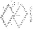
- the side-edge backlight moduleIn the side-edge backlight module, a unilateral or L-shaped light source is usually used. As shown in FIG. 3 , the side-edge backlight module is composed of a base box A, a light guide plate B, a L-shaped light source C, and a control circuit D.
- the L-shaped light source Cis composed of an array of red, blue, and green light emitting diodes (LEDs).
- the L-shaped light source Cis mounted on the edge of the light guide plate B, and the L-shaped light source C and the light guide plate B are mounted in the base box A together, wherein the L-shaped light source C is further connected the control circuit D such that the L-shaped light source C can utilize the light guide plate B for controlling the progress direction of the light.
- a major drawback of the side-edge backlight moduleconsists in that since the L-shaped light source C is located adjacent to the edges of the base box A, bright points, individual colors, and non-uniform mixing of lights on the edges are caused by the physical phenomenon of total reflection on the box's edges after the side-edge backlight module is electrified.
- the present inventormakes diligent studies in providing consumers with a light source structure of a backlight module that avoids the non-uniform mixing of lights on edges according to the motive of the present invention.
- a light source structure of a backlight modulecomprises: a bar-shaped light source; and a group of complementary color light emitting diodes mounted at both ends of the bar-shaped light source.
- the bar-shaped light sourceis composed of a plurality of light emitting diodes having complementary light colors.
- the luminous intensity of outermost light emitting diodes of the bar-shaped light sourceis 30 to 70% of average luminous intensity of other equal color light emitting diodes.
- the complementary color light emitting diodeshave light colors complementary to that of the outermost light emitting diodes of the bar-shaped light source.
- the luminous intensity of the complementary color light emitting diodesis 10 to 50% of average luminous intensity of the other equal color light emitting diodes of the bar-shaped light source. Consequently, the non-uniform mixing of lights on the edges of the backlight module can be avoided.
- FIG. 1is a decomposed view showing a preferred embodiment of the present invention.
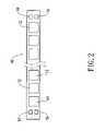
- FIG. 2is a top view showing a light source structure of the present invention.
- FIG. 3is a decomposed view showing a conventional side-edge backlight module.
- a backlight module 1 of the present inventioncomprises a box 40 , wherein a light guide plate 20 is mounted in the box 40 .
- a bar-shaped light source 10is mounted on one side of the light guide plate 20 , and the bar-shaped light source 10 is connected to a control circuit 30 .
- the bar-shaped light source 10is composed of a plurality light emitting diodes, which have complementary light colors. An exemplification will now be given with reference to FIG. 2 , where green, blue, and red LEDs 11 , 12 , and 13 are utilized in this preferred embodiment.
- the bar-shaped light source 10is composed of a plurality of green, blue, and red LEDs 11 , 12 , and 13 , which are spaced at equal intervals, wherein the luminous intensity of the outermost LEDs mounted respectively at both ends of the bar-shaped light source 10 is 30 to 70% of average luminous intensity of other equal color LEDs.
- two light sources with light colors complementary to that of the outermost LEDare mounted on upper and lower proper portions beside this outermost LED, wherein the luminous intensity of these light sources is 10 to 50% of average luminous intensity of the other equal color LEDs.
- the outermost LEDis a green LED 11
- a red LED 14 and a blue LED 15 with 10 to 50% of average luminous intensity of the other equal color LEDsare mounted on upper and lower proper portions beside this green LED 11 .
- a red LED 14 and a green LED 16 with 10 to 50% of average luminous intensity of the other equal color LEDsare mounted on upper and lower proper portions beside this blue LED 12 .
- the light sourcesred LED 14 /blue LED 15 and red LED 14 /green LED 16 ) with light colors complementary to that of the outermost LEDs, respectively, are mounted on upper and lower proper portions beside these outermost LEDs, wherein the luminous intensity of these light sources is 10 to 50% of average luminous intensity of the other equal color LEDs, whereby mirrorlike edges of the box 40 are prevented from the occurrence of total reflection phenomenon, which causes defects including non-uniform mixing of lights.
- the light source structure of the backlight module of the present inventionavoids the producing of the individual colors at both ends, which occur in the conventional side-edge backlight module. Accordingly, the present invention satisfies patentability and is submitted for a patent.
Landscapes
- Physics & Mathematics (AREA)
- General Physics & Mathematics (AREA)
- Optics & Photonics (AREA)
- Planar Illumination Modules (AREA)
- Liquid Crystal (AREA)
Abstract
Description
Claims (1)
Priority Applications (1)
| Application Number | Priority Date | Filing Date | Title |
|---|---|---|---|
| US11/284,824US7309152B2 (en) | 2005-11-23 | 2005-11-23 | Light source structure of backlight module |
Applications Claiming Priority (1)
| Application Number | Priority Date | Filing Date | Title |
|---|---|---|---|
| US11/284,824US7309152B2 (en) | 2005-11-23 | 2005-11-23 | Light source structure of backlight module |
Publications (2)
| Publication Number | Publication Date |
|---|---|
| US20070115648A1 US20070115648A1 (en) | 2007-05-24 |
| US7309152B2true US7309152B2 (en) | 2007-12-18 |
Family
ID=38053240
Family Applications (1)
| Application Number | Title | Priority Date | Filing Date |
|---|---|---|---|
| US11/284,824Active2025-12-15US7309152B2 (en) | 2005-11-23 | 2005-11-23 | Light source structure of backlight module |
Country Status (1)
| Country | Link |
|---|---|
| US (1) | US7309152B2 (en) |
Cited By (11)
| Publication number | Priority date | Publication date | Assignee | Title |
|---|---|---|---|---|
| US20080074902A1 (en)* | 2006-09-25 | 2008-03-27 | Samsung Electronics Co., Ltd. | Lcd backlight assembly with leds |
| US20080232134A1 (en)* | 2007-03-23 | 2008-09-25 | Promate Electronic Co., Ltd. | Replaceable LED light source device used in backlight module |
| USD585847S1 (en)* | 2006-09-08 | 2009-02-03 | Cree, Inc. | LED lighting tile |
| US20090213589A1 (en)* | 2008-02-15 | 2009-08-27 | Led Forward, Inc. | Led light fixture |
| US20100085762A1 (en)* | 2008-10-03 | 2010-04-08 | Peifer Donald A | Optimized spatial power distribution for solid state light fixtures |
| US20100110658A1 (en)* | 2008-10-08 | 2010-05-06 | Peifer Donald A | Semi-direct solid state lighting fixture and distribution |
| USD642578S1 (en)* | 2009-09-30 | 2011-08-02 | Sony Corporation | Memory card adapter |
| US20110273873A1 (en)* | 2010-05-06 | 2011-11-10 | Funai Electric Co., Ltd. | Light source unit |
| WO2017152494A1 (en)* | 2016-03-08 | 2017-09-14 | 武汉华星光电技术有限公司 | Backlight source structure of liquid crystal display and liquid crystal display |
| USD929031S1 (en) | 2018-07-16 | 2021-08-24 | Abl Ip Holding Llc | Lighting fixture |
| USD948777S1 (en) | 2018-07-16 | 2022-04-12 | Abl Ip Holding Llc | Lighting fixture |
Families Citing this family (4)
| Publication number | Priority date | Publication date | Assignee | Title |
|---|---|---|---|---|
| GB2467664B (en)* | 2007-10-23 | 2011-06-15 | Lg Display Co Ltd | Backlight assembly |
| KR101294849B1 (en)* | 2007-10-23 | 2013-08-08 | 엘지디스플레이 주식회사 | Backlight assemlby |
| TWI402571B (en)* | 2009-04-22 | 2013-07-21 | Advanced Optoelectronic Tech | Backlight module with complementary color zone |
| CN105093580B (en)* | 2015-08-06 | 2020-12-01 | 京东方科技集团股份有限公司 | An anti-peeping structure, a display panel, a backlight module and a display device |
Citations (10)
| Publication number | Priority date | Publication date | Assignee | Title |
|---|---|---|---|---|
| US6431728B1 (en)* | 2000-07-05 | 2002-08-13 | Whelen Engineering Company, Inc. | Multi-array LED warning lights |
| US20030012035A1 (en)* | 2001-07-12 | 2003-01-16 | Bernard Edwin I. | Programmable multi-color backlight for a liquid crystal display |
| US6608614B1 (en)* | 2000-06-22 | 2003-08-19 | Rockwell Collins, Inc. | Led-based LCD backlight with extended color space |
| US20030156416A1 (en)* | 2002-02-21 | 2003-08-21 | Whelen Engineering Company, Inc. | Led light assembly |
| US20040206964A1 (en)* | 2001-09-03 | 2004-10-21 | Toyoda Gosei Co., Ltd. | LED device and manufacturing method thereof |
| US20040218388A1 (en)* | 2003-03-31 | 2004-11-04 | Fujitsu Display Technologies Corporation | Surface lighting device and liquid crystal display device using the same |
| US6882111B2 (en)* | 2003-07-09 | 2005-04-19 | Tir Systems Ltd. | Strip lighting system incorporating light emitting devices |
| US20050276053A1 (en)* | 2003-12-11 | 2005-12-15 | Color Kinetics, Incorporated | Thermal management methods and apparatus for lighting devices |
| US20060104090A1 (en)* | 2004-11-12 | 2006-05-18 | Harris Corporation | LED light engine for backlighting a liquid crystal display |
| US20060221637A1 (en)* | 2005-03-31 | 2006-10-05 | Sharp Kabushiki Kaisha | Light source module, backlight unit, and liquid crystal display device |
- 2005
- 2005-11-23USUS11/284,824patent/US7309152B2/enactiveActive
Patent Citations (10)
| Publication number | Priority date | Publication date | Assignee | Title |
|---|---|---|---|---|
| US6608614B1 (en)* | 2000-06-22 | 2003-08-19 | Rockwell Collins, Inc. | Led-based LCD backlight with extended color space |
| US6431728B1 (en)* | 2000-07-05 | 2002-08-13 | Whelen Engineering Company, Inc. | Multi-array LED warning lights |
| US20030012035A1 (en)* | 2001-07-12 | 2003-01-16 | Bernard Edwin I. | Programmable multi-color backlight for a liquid crystal display |
| US20040206964A1 (en)* | 2001-09-03 | 2004-10-21 | Toyoda Gosei Co., Ltd. | LED device and manufacturing method thereof |
| US20030156416A1 (en)* | 2002-02-21 | 2003-08-21 | Whelen Engineering Company, Inc. | Led light assembly |
| US20040218388A1 (en)* | 2003-03-31 | 2004-11-04 | Fujitsu Display Technologies Corporation | Surface lighting device and liquid crystal display device using the same |
| US6882111B2 (en)* | 2003-07-09 | 2005-04-19 | Tir Systems Ltd. | Strip lighting system incorporating light emitting devices |
| US20050276053A1 (en)* | 2003-12-11 | 2005-12-15 | Color Kinetics, Incorporated | Thermal management methods and apparatus for lighting devices |
| US20060104090A1 (en)* | 2004-11-12 | 2006-05-18 | Harris Corporation | LED light engine for backlighting a liquid crystal display |
| US20060221637A1 (en)* | 2005-03-31 | 2006-10-05 | Sharp Kabushiki Kaisha | Light source module, backlight unit, and liquid crystal display device |
Cited By (17)
| Publication number | Priority date | Publication date | Assignee | Title |
|---|---|---|---|---|
| USD585847S1 (en)* | 2006-09-08 | 2009-02-03 | Cree, Inc. | LED lighting tile |
| US20080074902A1 (en)* | 2006-09-25 | 2008-03-27 | Samsung Electronics Co., Ltd. | Lcd backlight assembly with leds |
| US20080232134A1 (en)* | 2007-03-23 | 2008-09-25 | Promate Electronic Co., Ltd. | Replaceable LED light source device used in backlight module |
| US7914193B2 (en) | 2008-02-15 | 2011-03-29 | Lunera Lighting, Inc. | LED light fixture |
| US20090213589A1 (en)* | 2008-02-15 | 2009-08-27 | Led Forward, Inc. | Led light fixture |
| US7918598B2 (en) | 2008-02-15 | 2011-04-05 | Lunera Lighting, Inc. | LED light fixture |
| US7766536B2 (en) | 2008-02-15 | 2010-08-03 | Lunera Lighting, Inc. | LED light fixture |
| US20100277910A1 (en)* | 2008-02-15 | 2010-11-04 | Donald Allen Peifer | Led light fixture |
| US20100085762A1 (en)* | 2008-10-03 | 2010-04-08 | Peifer Donald A | Optimized spatial power distribution for solid state light fixtures |
| US20100110658A1 (en)* | 2008-10-08 | 2010-05-06 | Peifer Donald A | Semi-direct solid state lighting fixture and distribution |
| USD642578S1 (en)* | 2009-09-30 | 2011-08-02 | Sony Corporation | Memory card adapter |
| USD658185S1 (en) | 2009-09-30 | 2012-04-24 | Sony Corporation | Memory card adapter |
| US20110273873A1 (en)* | 2010-05-06 | 2011-11-10 | Funai Electric Co., Ltd. | Light source unit |
| US8608338B2 (en)* | 2010-05-06 | 2013-12-17 | Funai Electric Co., Ltd. | Light source unit |
| WO2017152494A1 (en)* | 2016-03-08 | 2017-09-14 | 武汉华星光电技术有限公司 | Backlight source structure of liquid crystal display and liquid crystal display |
| USD929031S1 (en) | 2018-07-16 | 2021-08-24 | Abl Ip Holding Llc | Lighting fixture |
| USD948777S1 (en) | 2018-07-16 | 2022-04-12 | Abl Ip Holding Llc | Lighting fixture |
Also Published As
| Publication number | Publication date |
|---|---|
| US20070115648A1 (en) | 2007-05-24 |
Similar Documents
| Publication | Publication Date | Title |
|---|---|---|
| US8104945B2 (en) | Backlight unit implementing local dimming for liquid crystal display device | |
| US7309152B2 (en) | Light source structure of backlight module | |
| US9176274B2 (en) | Backlight unit for liquid crystal display device | |
| CN100529899C (en) | Back lighting device | |
| US7872705B2 (en) | LED backlight system for LCD displays | |
| KR100691191B1 (en) | Surface light source using LED and LCD backlight unit having same | |
| US7270461B2 (en) | Backlight unit and liquid crystal display utilizing the same | |
| US7052152B2 (en) | LCD backlight using two-dimensional array LEDs | |
| US7630028B2 (en) | Color liquid crystal display having a blue light source and fluorescent wavelength conversion areas | |
| CN101349385B (en) | Backlight unit | |
| RU2502916C2 (en) | Lighting device, display device and television set | |
| JP5220381B2 (en) | Surface lighting device | |
| JPWO2008136359A1 (en) | Light emitting element and liquid crystal display device | |
| KR20070108736A (en) | LED backlight driving system | |
| CN103310739B (en) | direct type liquid crystal display device and driving method thereof | |
| US7740391B2 (en) | Backlight module | |
| KR100949194B1 (en) | LED lighting | |
| US20060203484A1 (en) | Light emitting diode, light emitting diode module, and related backlight system | |
| CN102252221A (en) | Luminaire | |
| US20100225848A1 (en) | Backlight device, and liquid crystal display using the same | |
| CN101320165B (en) | Colour liquid crystal display module group and its color displaying method | |
| US8045096B2 (en) | Lighting unit including alternately arrange first and second light sources, backlight unit, liquid crystal display device | |
| US20100201919A1 (en) | Liquid crystal display device | |
| WO2012058829A1 (en) | Light source module and backlight device | |
| US20090033688A1 (en) | Brightness adjusting method and device for an led-based display panel |
Legal Events
| Date | Code | Title | Description |
|---|---|---|---|
| AS | Assignment | Owner name:UNITY OPTO TECHNOLOGY CO., LTD., TAIWAN Free format text:ASSIGNMENT OF ASSIGNORS INTEREST;ASSIGNOR:HUANG, TAI-HO;REEL/FRAME:017268/0791 Effective date:20051108 | |
| STCF | Information on status: patent grant | Free format text:PATENTED CASE | |
| FEPP | Fee payment procedure | Free format text:PAT HOLDER NO LONGER CLAIMS SMALL ENTITY STATUS, ENTITY STATUS SET TO UNDISCOUNTED (ORIGINAL EVENT CODE: STOL); ENTITY STATUS OF PATENT OWNER: LARGE ENTITY | |
| REFU | Refund | Free format text:REFUND - SURCHARGE, PETITION TO ACCEPT PYMT AFTER EXP, UNINTENTIONAL (ORIGINAL EVENT CODE: R2551); ENTITY STATUS OF PATENT OWNER: LARGE ENTITY | |
| FPAY | Fee payment | Year of fee payment:4 | |
| FPAY | Fee payment | Year of fee payment:8 | |
| MAFP | Maintenance fee payment | Free format text:PAYMENT OF MAINTENANCE FEE, 12TH YEAR, LARGE ENTITY (ORIGINAL EVENT CODE: M1553); ENTITY STATUS OF PATENT OWNER: LARGE ENTITY Year of fee payment:12 | |
| AS | Assignment | Owner name:EPISTAR CORPORATION, TAIWAN Free format text:SECURITY INTEREST;ASSIGNOR:UNITY OPTO TECHNOLOGY CO., LTD.;REEL/FRAME:052291/0387 Effective date:20200212 | |
| AS | Assignment | Owner name:UNITY OPTO TECHNOLOGY CO., LTD.,, TAIWAN Free format text:RELEASE BY SECURED PARTY;ASSIGNOR:EPISTAR CORPORATION;REEL/FRAME:060250/0674 Effective date:20220309 Owner name:EPISTAR CORPORATION, TAIWAN Free format text:ASSIGNMENT OF ASSIGNORS INTEREST;ASSIGNOR:UNITY OPTO TECHNOLOGY CO., LTD.;REEL/FRAME:059496/0205 Effective date:20220309 |