US7308270B2 - Method and apparatus for high throughput multiple radio sectorized wireless cell - Google Patents
Method and apparatus for high throughput multiple radio sectorized wireless cellDownload PDFInfo
- Publication number
- US7308270B2 US7308270B2US11/160,549US16054905AUS7308270B2US 7308270 B2US7308270 B2US 7308270B2US 16054905 AUS16054905 AUS 16054905AUS 7308270 B2US7308270 B2US 7308270B2
- Authority
- US
- United States
- Prior art keywords
- antenna
- client
- wireless
- wireless cell
- antennas
- Prior art date
- Legal status (The legal status is an assumption and is not a legal conclusion. Google has not performed a legal analysis and makes no representation as to the accuracy of the status listed.)
- Expired - Fee Related
Links
- 238000000034methodMethods0.000titleclaimsabstractdescription68
- 238000004891communicationMethods0.000claimsdescription34
- 238000003860storageMethods0.000claimsdescription26
- 230000006866deteriorationEffects0.000claimsdescription2
- 230000002452interceptive effectEffects0.000abstractdescription13
- 238000010586diagramMethods0.000description62
- 230000008859changeEffects0.000description24
- 230000005540biological transmissionEffects0.000description20
- 230000007423decreaseEffects0.000description16
- 239000000463materialSubstances0.000description10
- 230000006870functionEffects0.000description9
- 238000013459approachMethods0.000description8
- 230000003068static effectEffects0.000description8
- 230000000694effectsEffects0.000description7
- 230000007613environmental effectEffects0.000description7
- 230000008569processEffects0.000description7
- 230000003044adaptive effectEffects0.000description6
- 238000004422calculation algorithmMethods0.000description6
- 230000008901benefitEffects0.000description5
- 230000010354integrationEffects0.000description5
- 10171008312950S ribosomal protein L10, chloroplasticProteins0.000description4
- 10171011476250S ribosomal protein L11, chloroplasticProteins0.000description4
- 238000003491arrayMethods0.000description4
- 239000002184metalSubstances0.000description4
- 229910052751metalInorganic materials0.000description4
- 10171014963650S ribosomal protein L18, chloroplasticProteins0.000description3
- 230000002238attenuated effectEffects0.000description3
- 238000011161developmentMethods0.000description3
- 230000000670limiting effectEffects0.000description3
- 239000004033plasticSubstances0.000description3
- 238000012545processingMethods0.000description3
- 238000012546transferMethods0.000description3
- 10171008241450S ribosomal protein L12, chloroplasticProteins0.000description2
- 10171016499450S ribosomal protein L13, chloroplasticProteins0.000description2
- 10171012569050S ribosomal protein L17, chloroplasticProteins0.000description2
- OKTJSMMVPCPJKN-UHFFFAOYSA-NCarbonChemical compound[C]OKTJSMMVPCPJKN-UHFFFAOYSA-N0.000description2
- 238000004590computer programMethods0.000description2
- 230000003247decreasing effectEffects0.000description2
- 239000011521glassSubstances0.000description2
- 230000001771impaired effectEffects0.000description2
- 230000003287optical effectEffects0.000description2
- 238000005457optimizationMethods0.000description2
- 230000008520organizationEffects0.000description2
- 230000002829reductive effectEffects0.000description2
- 230000035945sensitivityEffects0.000description2
- XLYOFNOQVPJJNP-UHFFFAOYSA-NwaterSubstancesOXLYOFNOQVPJJNP-UHFFFAOYSA-N0.000description2
- 240000004282Grewia occidentalisSpecies0.000description1
- VVQNEPGJFQJSBK-UHFFFAOYSA-NMethyl methacrylateChemical compoundCOC(=O)C(C)=CVVQNEPGJFQJSBK-UHFFFAOYSA-N0.000description1
- 240000000022Silene vulgarisSpecies0.000description1
- 235000011312Silene vulgarisNutrition0.000description1
- 239000011358absorbing materialSubstances0.000description1
- 230000009471actionEffects0.000description1
- 238000004364calculation methodMethods0.000description1
- 229910052799carbonInorganic materials0.000description1
- 239000000919ceramicSubstances0.000description1
- 239000002131composite materialSubstances0.000description1
- 230000008878couplingEffects0.000description1
- 238000010168coupling processMethods0.000description1
- 238000005859coupling reactionMethods0.000description1
- 238000005520cutting processMethods0.000description1
- 238000001514detection methodMethods0.000description1
- 239000004744fabricSubstances0.000description1
- 239000010439graphiteSubstances0.000description1
- 229910002804graphiteInorganic materials0.000description1
- 230000006872improvementEffects0.000description1
- 239000002648laminated materialSubstances0.000description1
- 238000004519manufacturing processMethods0.000description1
- 239000007769metal materialSubstances0.000description1
- 238000012544monitoring processMethods0.000description1
- 230000006855networkingEffects0.000description1
- 230000010287polarizationEffects0.000description1
- 230000009467reductionEffects0.000description1
- 230000004044responseEffects0.000description1
- 238000005070samplingMethods0.000description1
- 239000007787solidSubstances0.000description1
- 239000000126substanceSubstances0.000description1
- 230000001629suppressionEffects0.000description1
- 238000012360testing methodMethods0.000description1
Images


Classifications
- H—ELECTRICITY
- H04—ELECTRIC COMMUNICATION TECHNIQUE
- H04W—WIRELESS COMMUNICATION NETWORKS
- H04W16/00—Network planning, e.g. coverage or traffic planning tools; Network deployment, e.g. resource partitioning or cells structures
- H04W16/02—Resource partitioning among network components, e.g. reuse partitioning
- H04W16/12—Fixed resource partitioning
- H—ELECTRICITY
- H01—ELECTRIC ELEMENTS
- H01Q—ANTENNAS, i.e. RADIO AERIALS
- H01Q3/00—Arrangements for changing or varying the orientation or the shape of the directional pattern of the waves radiated from an antenna or antenna system
- H01Q3/26—Arrangements for changing or varying the orientation or the shape of the directional pattern of the waves radiated from an antenna or antenna system varying the relative phase or relative amplitude of energisation between two or more active radiating elements; varying the distribution of energy across a radiating aperture
- H01Q3/2605—Array of radiating elements provided with a feedback control over the element weights, e.g. adaptive arrays
- H—ELECTRICITY
- H04—ELECTRIC COMMUNICATION TECHNIQUE
- H04B—TRANSMISSION
- H04B17/00—Monitoring; Testing
- H04B17/30—Monitoring; Testing of propagation channels
- H04B17/382—Monitoring; Testing of propagation channels for resource allocation, admission control or handover
- H—ELECTRICITY
- H04—ELECTRIC COMMUNICATION TECHNIQUE
- H04B—TRANSMISSION
- H04B7/00—Radio transmission systems, i.e. using radiation field
- H04B7/02—Diversity systems; Multi-antenna system, i.e. transmission or reception using multiple antennas
- H04B7/022—Site diversity; Macro-diversity
- H—ELECTRICITY
- H04—ELECTRIC COMMUNICATION TECHNIQUE
- H04B—TRANSMISSION
- H04B7/00—Radio transmission systems, i.e. using radiation field
- H04B7/02—Diversity systems; Multi-antenna system, i.e. transmission or reception using multiple antennas
- H04B7/04—Diversity systems; Multi-antenna system, i.e. transmission or reception using multiple antennas using two or more spaced independent antennas
- H04B7/0408—Diversity systems; Multi-antenna system, i.e. transmission or reception using multiple antennas using two or more spaced independent antennas using two or more beams, i.e. beam diversity
- H—ELECTRICITY
- H04—ELECTRIC COMMUNICATION TECHNIQUE
- H04B—TRANSMISSION
- H04B7/00—Radio transmission systems, i.e. using radiation field
- H04B7/02—Diversity systems; Multi-antenna system, i.e. transmission or reception using multiple antennas
- H04B7/04—Diversity systems; Multi-antenna system, i.e. transmission or reception using multiple antennas using two or more spaced independent antennas
- H04B7/0491—Diversity systems; Multi-antenna system, i.e. transmission or reception using multiple antennas using two or more spaced independent antennas using two or more sectors, i.e. sector diversity
- H04B7/0495—Diversity systems; Multi-antenna system, i.e. transmission or reception using multiple antennas using two or more spaced independent antennas using two or more sectors, i.e. sector diversity using overlapping sectors in the same base station to implement MIMO for antennas
- H—ELECTRICITY
- H04—ELECTRIC COMMUNICATION TECHNIQUE
- H04W—WIRELESS COMMUNICATION NETWORKS
- H04W16/00—Network planning, e.g. coverage or traffic planning tools; Network deployment, e.g. resource partitioning or cells structures
- H—ELECTRICITY
- H04—ELECTRIC COMMUNICATION TECHNIQUE
- H04W—WIRELESS COMMUNICATION NETWORKS
- H04W16/00—Network planning, e.g. coverage or traffic planning tools; Network deployment, e.g. resource partitioning or cells structures
- H04W16/02—Resource partitioning among network components, e.g. reuse partitioning
- H—ELECTRICITY
- H04—ELECTRIC COMMUNICATION TECHNIQUE
- H04W—WIRELESS COMMUNICATION NETWORKS
- H04W16/00—Network planning, e.g. coverage or traffic planning tools; Network deployment, e.g. resource partitioning or cells structures
- H04W16/14—Spectrum sharing arrangements between different networks
- H—ELECTRICITY
- H04—ELECTRIC COMMUNICATION TECHNIQUE
- H04W—WIRELESS COMMUNICATION NETWORKS
- H04W16/00—Network planning, e.g. coverage or traffic planning tools; Network deployment, e.g. resource partitioning or cells structures
- H04W16/24—Cell structures
- H—ELECTRICITY
- H04—ELECTRIC COMMUNICATION TECHNIQUE
- H04W—WIRELESS COMMUNICATION NETWORKS
- H04W28/00—Network traffic management; Network resource management
- H04W28/16—Central resource management; Negotiation of resources or communication parameters, e.g. negotiating bandwidth or QoS [Quality of Service]
- H—ELECTRICITY
- H04—ELECTRIC COMMUNICATION TECHNIQUE
- H04W—WIRELESS COMMUNICATION NETWORKS
- H04W40/00—Communication routing or communication path finding
- H04W40/02—Communication route or path selection, e.g. power-based or shortest path routing
- H—ELECTRICITY
- H04—ELECTRIC COMMUNICATION TECHNIQUE
- H04W—WIRELESS COMMUNICATION NETWORKS
- H04W74/00—Wireless channel access
- H04W74/04—Scheduled access
- H04W74/06—Scheduled access using polling
- H—ELECTRICITY
- H04—ELECTRIC COMMUNICATION TECHNIQUE
- H04W—WIRELESS COMMUNICATION NETWORKS
- H04W88/00—Devices specially adapted for wireless communication networks, e.g. terminals, base stations or access point devices
- H04W88/02—Terminal devices
- H04W88/06—Terminal devices adapted for operation in multiple networks or having at least two operational modes, e.g. multi-mode terminals
- Y—GENERAL TAGGING OF NEW TECHNOLOGICAL DEVELOPMENTS; GENERAL TAGGING OF CROSS-SECTIONAL TECHNOLOGIES SPANNING OVER SEVERAL SECTIONS OF THE IPC; TECHNICAL SUBJECTS COVERED BY FORMER USPC CROSS-REFERENCE ART COLLECTIONS [XRACs] AND DIGESTS
- Y02—TECHNOLOGIES OR APPLICATIONS FOR MITIGATION OR ADAPTATION AGAINST CLIMATE CHANGE
- Y02D—CLIMATE CHANGE MITIGATION TECHNOLOGIES IN INFORMATION AND COMMUNICATION TECHNOLOGIES [ICT], I.E. INFORMATION AND COMMUNICATION TECHNOLOGIES AIMING AT THE REDUCTION OF THEIR OWN ENERGY USE
- Y02D30/00—Reducing energy consumption in communication networks
- Y02D30/70—Reducing energy consumption in communication networks in wireless communication networks
Definitions
- This inventiongenerally relates to wireless communications, and more particularly, to systems and methods for wireless cells, access points, and clients.
- the enhanced antenna systemincludes at least one of sectorized coverage, attenuation, overlapping or non-overlapping antenna physical sector arrangements, and minimally interfering radio channels to enable multiple antennas and multiple radios to substantially simultaneously operate in a single wireless cell and to provide increased throughput, while minimizing the interference with foreign wireless systems.
- a hornmay also enable any antenna type to function as a directional antenna and to provide either overlapping or non-overlapping antenna physical sector arrangements, while at least one of reducing interference from behind the antenna, interference between adjacent antennas, and multi-path interference.
- the inventionmay also include inexpensive, off-the-shelf radios with diversity switches to automatically select between directional antennas used in an enhanced antenna system where the physical sectors of the two antennas connected to a single radio may be oriented about 180 degrees opposed to each other.
- the enhanced antenna systemmay also be used on apparatus that function as clients to a wireless cell.
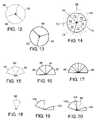
- FIG. 1is a diagram of an exemplary area of coverage of an omni-directional antenna.
- FIG. 2is a diagram of an exemplary area of coverage, or physical sector, of a directional antenna.
- FIG. 3is a diagram of three exemplary adjacent physical sectors.
- FIG. 4is a diagram of two exemplary overlapping physical sectors forming an exemplary virtual sector.
- FIG. 5is a diagram of two exemplary adjacent and one exemplary overlapping physical sectors forming two exemplary virtual sectors.
- FIG. 6is an exemplary diagram of optimal and absolute maximum coverage distance and areas.
- FIG. 7is an exemplary diagram of the maximum transmit physical sector size when the radio is at maximum power.
- FIG. 8is a diagram of an exemplary physical sector size when the radio is at less than maximum power.
- FIG. 9is a diagram of an exemplary maximum receive physical sector size when the attenuator provides no attenuation.
- FIG. 10is a diagram of an exemplary physical sector size when the attenuator attenuates.
- FIG. 11is a diagram of an exemplary maximum transmit physical sector overlaid on a non-maximum receive physical sector.
- FIG. 12is a diagram of three exemplary adjacent, non-overlapping physical sectors providing about 360-degree coverage.
- FIG. 13is a diagram of three exemplary adjacent, non-overlapping physical sectors providing about 360-degree coverage with orientation different than physical sectors of FIG. 12 .
- FIG. 14is a diagram of six exemplary overlapping physical sectors forming six virtual sectors and providing about 360-degree coverage.
- FIG. 15is a diagram of three exemplary adjacent, non-overlapping physical sectors.
- FIG. 16is a diagram of four exemplary adjacent, non-overlapping physical sectors with orientation different than the physical sectors of FIG. 15 .
- FIG. 17is a diagram of seven exemplary overlapping physical sectors forming six virtual sectors and providing about 180-degree coverage.
- FIG. 18is a diagram of an exemplary physical sector of a single directional antenna.
- FIG. 19is a diagram of two exemplary non-overlapping, non-adjacent physical sectors.
- FIG. 20is a diagram of three exemplary physical sectors wherein two physical sectors overlap and form a virtual sector.
- FIG. 21is a diagram of exemplary wireless cells, or access points, in individual apartments.
- FIG. 22is a block diagram of an exemplary six antenna, three-radio wireless cell.
- FIG. 23is a block diagram of an exemplary six antenna, three-radio wireless cell with an attenuator in each radio receive path.
- FIG. 24is a block diagram of an exemplary six antenna, three-radio wireless cell with an attenuator in each antenna path.
- FIG. 25is a block diagram of an exemplary four antenna, two-radio wireless cell.
- FIG. 26is a block diagram of an exemplary four antenna, two-radio wireless cell with an attenuator in each radio receive path.
- FIG. 27is a block diagram of an exemplary four antenna, two-radio wireless cell with an attenuator in each antenna path.
- FIG. 28is a block diagram of an exemplary two-antenna, client enhanced antenna system.
- FIG. 29is a block diagram of an exemplary four-antenna, client enhanced antenna system.
- FIG. 30is a block diagram of an exemplary two-antenna, client enhanced antenna system with an attenuator in the radio receive path.
- FIG. 31is a block diagram of an exemplary four-antenna, client enhanced antenna system with an attenuator in the radio receive path.
- FIG. 32is a diagram of an exemplary coverage pattern for two, non-overlapping directional antennas providing about 360-degree coverage.
- FIG. 33is a diagram of an exemplary coverage pattern of two, non-overlapping directional antennas providing about 360-degree coverage with orientation different than the coverage pattern of FIG. 32 .
- FIG. 34is a diagram of an exemplary coverage of four overlapping physical sectors providing about 360-degree coverage and forming four virtual sectors.
- FIG. 35is a diagram of an exemplary horn.
- FIG. 36is a diagram of an exemplary antenna positioned in a horn to reduce angle of coverage.
- FIG. 37is a diagram of an exemplary antenna positioned in a horn to increase angle of coverage.
- FIG. 38is a diagram of an exemplary omni-directional antenna positioned in a horn to provide directional coverage.
- FIG. 39is a diagram of an exemplary group of horns positioned to provide about 360-degree overlapping or non-overlapping coverage.
- FIG. 40is a diagram of an exemplary channel assignment using three channels for three, adjacent, non-overlapping physical sectors providing about 360-degree coverage.
- FIG. 41is a diagram of an exemplary channel assignment using two channels for six, adjacent, non-overlapping physical sectors providing about 360-degree coverage.
- FIG. 42is a diagram of an exemplary channel assignment using three channels for six, adjacent, non-overlapping physical sectors providing about 360-degree coverage.
- FIG. 43is a diagram of an exemplary channel assignment using six channels for six, adjacent, non-overlapping physical sectors providing about 360-degree coverage.
- FIG. 44is a diagram of an exemplary channel assignment using two channels for four, adjacent, non-overlapping physical sectors providing about 180-degree coverage.
- FIG. 45is a diagram of an exemplary channel assignment using three channels for four, adjacent, non-overlapping physical sectors providing about 180-degree coverage.
- FIG. 46is a diagram of an exemplary channel assignment using four channels for four, adjacent, non-overlapping physical sectors providing about 180-degree coverage.
- FIG. 47is a diagram of an exemplary channel assignment using two channels for three, adjacent, non-overlapping physical sectors.
- FIG. 48is a diagram of an exemplary channel assignment using three channels for three, adjacent, non-overlapping physical sectors.
- FIG. 49is a diagram of an exemplary channel assignment using one channel for two, non-adjacent, non-overlapping physical sectors.
- FIG. 50is a diagram of an exemplary channel assignment using one channel for one physical sector.
- FIG. 51is a diagram of an exemplary wireless cell formed using three, adjacent, non-overlapping physical sectors providing about 360-degree coverage and having a channel assigned to each physical sector.
- FIG. 52is a diagram of an exemplary wireless cell formed using three, adjacent, non-overlapping physical sectors providing about 360-degree coverage with orientation different than the wireless cell shown in FIG. 51 and having a channel assigned to each physical sector.
- FIG. 53is a diagram of an exemplary wireless cell formed using six overlapping physical sectors that form six virtual sectors and provides about 360-degree coverage.
- FIG. 54is a diagram of an exemplary wireless cell formed using four, adjacent, non-overlapping physical sectors providing about 180-degree coverage and having a channel assigned to each physical sector.
- FIG. 55is a diagram of an exemplary wireless cell formed using three, adjacent, non-overlapping physical sectors providing about 180-degree coverage with orientation different than the wireless cell shown in FIG. 54 and having a channel assigned to each physical sector.
- FIG. 56is a diagram of an exemplary wireless cell formed using seven overlapping physical sectors that form six virtual sectors.
- FIG. 57is a diagram of an exemplary wireless cell with four non-overlapping physical sectors providing about 180-degree coverage and servicing clients.
- FIG. 58is a diagram of an exemplary wireless cell with six overlapping physical sectors providing about 360-degree coverage and servicing clients.
- FIG. 59is a diagram of an exemplary client using a two-antenna, client enhanced antenna system placed in an environment of three foreign wireless cells.
- FIG. 60is a diagram of an exemplary client using a four-antenna, client enhanced antenna system placed in an environment of three foreign wireless cells.
- FIG. 61is a flow chart of a method for performing an exemplary active scan.
- FIG. 62is a flow chart of a method for performing an exemplary power on initialization.
- FIG. 63is a flow chart of a method for performing an exemplary background loop.
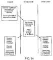
- FIG. 64is a flow chart of an exemplary method for a client to inform the wireless cell that the throughput of the assigned channel is insufficient.
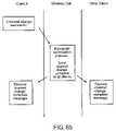
- FIG. 65is a flow chart of an exemplary method for advising the wireless cell that the channel change was successful.
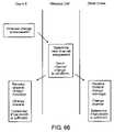
- FIG. 66is a flow chart of an exemplary method for advising the wireless cell that the new channel does not provide sufficient throughput.
- FIG. 67is a flow chart of an exemplary method for advising the wireless cell that a channel change has impaired performance.
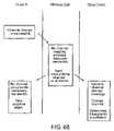
- FIG. 68is a flow chart of an exemplary method for the wireless cell to advise the client that no channel may provide sufficient throughput.
- the present inventionmay be embodied as a customization of an existing system, an add-on product, upgraded software, a stand alone system, a distributed system, a method, a data processing system, a device for data processing, and/or a computer program product. Accordingly, the present invention may take the form of an entirely software embodiment, an entirely hardware embodiment, or an embodiment combining aspects of both software and hardware. Furthermore, the present invention may take the form of a computer program product on a computer-readable storage medium having computer-readable program code means embodied in the storage medium. Any suitable computer-readable storage medium may be utilized, including hard disks, CD-ROM, optical storage devices, magnetic storage devices, and/or the like.
- An omni-directional antenna 10sends and receives radio signals in substantially all directions.
- the ideal area of coverage 12ignoring any null areas, of the omni-directional antenna 10 in FIG. 1 is substantially circular because it is shown on paper in two dimensions, but in reality, the ideal area of coverage of an omni-directional antenna is similar to a sphere.
- the ideal area of coverage 16ignoring any back-lobes, of the directional antenna 14 in FIG. 2 is shown in two dimensions as a part of a circle; however, in reality, the ideal area of coverage of a directional antenna is an angular fraction of a sphere.
- the arc 18indicates the angle of coverage of directional antenna 14 and area of coverage 16 .
- the angle of coverage of a directional antennaranges from a fraction more than 0 degrees to a fraction less than about 360 degrees.
- the operational center of directional antenna 14is the center of its angular area of coverage. For example, the angle of coverage of antenna 14 is about 20 degrees, but its operational center is at about 10 degrees.
- the line depicting the antenna area of coveragedoes not necessarily indicate the maximum range of the radio attached to the antenna.
- the circle labeled 12 in FIG. 1does not necessarily mean that the radio attached to omni-directional antenna 10 cannot transmit farther than area of coverage 12 .
- Circle 12may depict the absolute transmission or reception limit, but it may also represent the distance at which most radio signals decrease to a predetermined signal strength while the maximum limits may extend beyond circle 12 .
- the same conceptapplies to the area of coverage of a directional antenna; however, the angle of coverage 18 may not change appreciably.
- the distance 328 from directional antenna 14 in FIG. 6 to the outer edge of area of coverage 330represents the absolute maximum distance that a signal of detectable strength may be transmitted or received by the radio attached to antenna 14 .
- the distance 326 and the dash area of coverage 324represent the extent of usable signal strength coverage for reliable transmission.
- a client position inside area of coverage 324may receive the minimum usable radio signal strength.
- a client outside area of coverage 324may still be detected by antenna 14 , but the client may receive signals with less than usable signal strength.
- the angle of coveragedoes not change appreciably between optimal area of coverage 324 and absolute maximum area of coverage 330 because directional antennas attenuate signals at the edge of their angle of coverage.
- any area of coverage drawndoes not necessarily represent the maximum limits of transmission and reception 330 , but rather, the area represents the usable signal level area of coverage 324 . Therefore, two adjacent areas of coverage may interfere with each other to some extent even though their drawn areas of coverage are not shown to overlap. Referring to FIG. 21 , the drawn areas of coverage of the directional antennas of room 112 do not overlap with the areas of coverage of the directional antennas of rooms 106 or 114 ; however, if the maximum extent of all the antennas were shown, they may interfere with each other.
- the area of coverage 16 of directional antenna 14is also referred to as a physical sector.
- Three adjacent physical sectors, 16 , 22 , and 28 , of antennas 14 , 20 , and 26are shown in FIG. 3 .
- antennas 14 , 20 , and 26are directional, the radio signals along their contiguous side may be attenuated. Therefore, adjacent physical sectors that use the same radio channel (frequency) may interfere with each other, but the amount of interference may be controlled, in one embodiment, through selecting directional antennas with high attenuation at the edges of their physical sector, by placing the directional antennas with extra angular spacing between them, or by using a horn as described below.
- each antenna 14 , 20 , and 26has an angle of coverage of 20 degrees. If antennas 14 , 20 , and 26 are positioned so that their combined angle of coverage is 60 degrees (i.e., 20 degrees each), then they do not overlap.
- the area of overlap of physical sectors 16 and 22 in FIG. 4may be referred to as a virtual sector 24 .
- the size of virtual sector 24is the amount of overlap between physical sectors 16 and 22 .
- Virtual sectorsmay range in size from a small fraction of a physical sector to the entire sector if the physical sectors completely overlap. Overlapping physical sectors do not need to be of similar size and the amount of overlap is not fixed.
- the physical sectors 16 , 22 , and 28 in FIG. 5are all similar in size. Physical sector 16 overlaps half of physical sector 22 and forms virtual sector 30 , which is about half the size of either physical sector 16 or 22 .
- Physical sectors 22 and 28also overlap by about half their angular width and form virtual sector 32 .
- physical sector 22overlaps 50% each of adjacent physical sectors 16 and 28 .
- the area of coverage within a virtual sectormay receive antenna, and therefore radio, coverage from more than one source.
- Virtual sectors 24 or 30may receive coverage from antennas 14 and 20 .
- Virtual sector 32may receive coverage from antennas 20 and 26 . If antennas 14 and 20 are attached to different radios, then the virtual sectors are serviced by two radios instead of the single radio that services either physical sector. There are no limits to how many physical sectors may overlap, which means that multiple antennas and multiple radios may service a virtual sector. The advantage of overlapping sectors will become apparent when enhanced antenna systems and wireless cells using enhanced antenna systems are described below.
- Antennasmay be connected to radios such that the radio may communicate with other apparatus.
- radiostransmit and receive information through a channel or set of channels that may be associated in some way to radio frequencies.
- Two apparatustypically use the same channel in order to communicate. Communication occurs when two apparatus use the same channel to transmit to each other or receive from each other. If two apparatus simultaneously transmit on the same channel, the transmissions may interfere with each other and may be made unintelligible.
- two apparatus set to different channelsmay interfere with each other. However, some channels interfere only minimally with each other when transmitting in the same area simultaneously. Two radios using different, minimally interfering channels interfere with each other only minimally when simultaneously transmitting.
- the 802.11 protocolsprovide minimally interfering channels that allow radios using different channels to operate simultaneously in the same physical area. Minimally interfering channels are advantageous when using overlapping or adjacent physical sectors. As discussed above, physical sectors 16 and 22 in FIG. 3 interfere with each other to some extent when they use the same channel because they are adjacent. Overlapping physical sectors, as shown in FIG. 4 and FIG. 5 , may interfere with each other even more than adjacent physical sectors if each physical sector were assigned the same channel. However, the radios do not interfere with each other even though the physical sectors are adjacent or overlapping, if the radios attached to the antennas of adjacent or overlapping physical sectors use different minimally interfering channels. The assignment of channels to overlapping and adjacent physical sectors plays an important role in enabling multiple radios to operate simultaneously in the same or nearby physical space.
- the area of coverage of an antenna and its associated radioi.e., the size of the physical sector
- An antenna, with its attached radiohas a greater area of coverage, and thereby a larger physical sector, if it transmits strong signals and detects weak signals.
- the radiomay control the strength of the transmitted signal. Adjusting the transmit power of an off-the-self radio changes the area of coverage, or size, of the antenna's physical sector.
- the physical sector 34 and distance 36 shown in FIG. 7represents the size of the physical sector when the radio transmits at maximum power. As radio transmission power decreases, physical sector size 38 and distance 40 , as shown in FIG. 8 , also decrease.
- the size of the transmit physical sectormay also be adjusted by using an attenuator in the transmit path.
- the size of the receive sectormay be adjusted using variable gain. Both transmit and receive physical sector sizes may be simultaneously adjusted if an attenuator is placed between the radio and the antenna thereby affecting both the transmit and receive paths substantially equally. Obviously, the size of the transmit and receive physical sectors may be adjusted independently.
- FIG. 11shows a maximum transmit physical sector 34 and a non-maximum receive physical sector 46 .
- the utility of independently adjustable transmit and receive physical sector sizesbecomes apparent when methods of dealing with noisy foreign clients are discussed; however, decreasing the size of the receive physical sector reduces the interference of noisy and unwanted sources.
- One of the main strategiesis to reduce the size of the receive physical sector to the point that unwanted noise is reduced without cutting off communication with desirable clients, while at the same time transmitting a strong signal to all clients within the transmit physical sector. Attenuation may also be adjusted to provide optimal data throughput between a wireless cell and a client.
- a wireless cellincludes, for example, a collection of antennas, radios, and potentially other devices (e.g., attenuators, RF switches, etc.) under the common control of a processor or multiple processors.
- An exemplary wireless cellcommunicates with other wireless cells, wireless clients, or other wireless devices.
- One embodiment of a wireless cellis an access point, which combines wireless communication with an I/O port connected to a wired network thereby allowing communication between wired and wireless devices.
- the cell's coveragemeaning the physical area serviced wirelessly, depends on the number, type, physical sector size, and arrangement of the antennas.
- the coverage of a wireless cell that uses an omni-directional antennais ideally a sphere type shape as shown in two dimensions in FIG. 1 .
- Directional antennasprovide greater flexibility in providing wireless cell coverage.
- the physical sectors from three, 120-degree, directional antennascombine to provide about 360-degree, non-overlapping wireless cell coverage as shown in FIG. 12 or FIG. 13 .
- the orientation of the antennas in FIG. 12vary from the antennas of FIG. 13 by about 60 degrees. If the antennas from FIG. 12 were combined with the antennas of FIG. 13 into the same wireless cell while preserving their orientation, the wireless cell may have the coverage shown in FIG. 14 .
- the wireless cell coverage of FIG. 14has six overlapping physical sectors: 56 , 58 , 60 , 62 , 64 , and 66 .
- Each physical sectoris similar size and overlaps about half of two adjacent physical sectors. For example, physical sector 60 overlaps about half of physical sector 66 and about half of physical sector 64 .
- Each physical sectoroverlaps two adjacent, non-overlapping physical sectors to form six virtual sectors: 68 , 70 , 72 , 74 , 76 , and 78 .
- Each virtual sectorincludes about 60-degree angle of coverage.
- FIG. 14shows physical sectors of substantially equal size, but, as mentioned earlier, the physical sectors are not limited to having substantially equal angle of coverage, nor do they need to be of substantially equal transmit or receive size. Additionally, in FIG. 14 , each virtual sector is formed by the overlap of two physical sectors, but the number of physical sectors that overlap to form a virtual sector is not limited. Wireless cell coverage depends on the characteristics of the individual physical sectors and how they combine. There are no requirements or limitations on size or method of combination; however, when providing about 360-degree wireless cell coverage, one embodiment includes physical sectors of substantially equal sizes that substantially equally overlap two non-overlapping and adjacent sectors. Wireless cell coverage does not need to be only 360 degrees.
- the three, non-overlapping, adjacent, physical sectors of FIG. 15provide wireless cell coverage that is less than about 180 degrees.
- Four non-overlapping, adjacent, physical sectors shown in FIG. 16provide about 180-degree wireless cell coverage.
- the combination of the wireless cell coverage from FIG. 15 and FIG. 16form the wireless cell coverage shown in FIG. 17 .
- physical sector 80overlaps physical sectors 86 and 88 thereby forming two virtual sectors and physical sector 84 overlaps physical sectors 90 and 92 thereby also forming two virtual sectors.
- FIG. 18shows an exemplary coverage of a wireless cell based on a single directional antenna.
- the wireless cell coverage shown in FIG. 19is formed by two, non-adjacent physical sectors of different sizes.
- the combination of the wireless cell areas of coverage of FIG. 18 and FIG. 19 into a single wireless cellresults in the wireless cell coverage shown in FIG. 20 .
- the overlap of physical sector 98 and 100form virtual sector 104 .
- wireless cell coveragemay depend on, for example, the number, type, physical sector size, and arrangement of the antennas forming the wireless cell.
- Wireless cellsmay include related and unrelated (i.e., foreign) wireless cells. Wireless cells may be related if they have some level of common control. Generally, related wireless cells form a wireless network capable of, for example, routing between wireless cells, collectively assigning channels to avoid interference, and automatic physical sector size adjustment. Foreign wireless cells are independent wireless cells with no central method of control or method of peer-to-peer control. For example, imagine each rectangular box in FIG. 21 to be an apartment in a building. Apartments 106 , 110 , 112 , 114 , and 116 have each set up wireless cells. The wireless cells in different apartments are not related. They are foreign to each other. No substantial set up or control communications takes place between the wireless cells in different apartments and no common processor coordinates them.
- the wireless cellsdo not collectively decide which channel should be assigned to each physical sector to minimize interference between apartments. If a wireless cell in one apartment assigns channels that interfere with a wireless cell in another apartment, the wireless cells do not coordinate between themselves to reduce interference because they are foreign to each other.
- An antenna-sharing deviceenables two different radio signal sources to share the same antenna.
- the ASD 148 shown in FIG. 23combines the transmit path 160 from radio 136 with the receive path 162 into a transmit/receive path connected to RF switch 130 .
- a clientmay be any type of wireless apparatus that communicates or cooperates with a wireless cell.
- a clientmay be distinguished from a wireless cell in that a client generally communicates only with a single wireless cell whereas a wireless cell communicates with many clients.
- the definitionshould not be limiting because one wireless cell may appear to be a client to another wireless cell.
- Another definition of a clientis that a client either produces or consumes data, whereas wireless cells generally only transfer data between wired or wireless sources. Some information is produced and consumed by wireless cells, but usually the information is related to the control of communications between wireless cells, or between wireless cells and clients.
- a clientis a device that associates with and uses the network services of access points.
- Clientsmay have one or more radios and one or more antennas.
- a clientmay function as a slave to a wireless cell or the client may work in conjunction with the wireless cell by transmitting control information and requests to the wireless cell in addition to data.
- Control information from a clientmay include, for example, signal quality, desired antenna, error rate, number of dropped frames, desired throughput, throughput delivered, wireless cells detected, and/or any other conceivable information.
- Client requestsmay include, for example, retransmission, channel change, throughput demands, authentication, variation in transmit power, and/or a request to modify any communication factor.
- Clientsare not limited to communicating only with wireless cells. In the ad hoc mode, clients may communicate directly with each other without the central coordination of a wireless cell. The advanced clients described in this application are not limited to communicating with wireless cells. Advanced clients are also capable of operating in the ad hoc mode.
- Advanced clientsmay communicate control information to a wireless cell. All clients may associate with a wireless cell and may send data to and receive data from a wireless cell, but advanced clients may send the wireless cell information that helps the wireless cell manage its communication with the clients it serves. An advanced client may inform the wireless cell, for example, of its desired throughput, buffer fullness, signal quality, and/or other relevant information.
- Wireless cells, access points, clients, or other devices that communicate using antennasmay use an enhanced antenna system.
- An enhanced antenna systemmay use, for example, an antenna physical sector arrangement, switching, and attenuation to increase receive sensitivity, reduce the effects of noise, provide improved coverage, provide increased transmission range, and/or to allow higher antenna density as compared to a simple antenna.
- An enhanced antenna systemmay, for example, combine antennas with other apparatus, use antenna positioning, shielding, channel assignment, intermittent use, noise sampling, operational protocols, and/or a combination of techniques to improve performance.
- An enhanced antenna systemmay include one or more antennas of various types such as, for example, omni-directional, directional, patch, parabolic, beam, yagi, MIMO, antenna arrays, adaptive antenna arrays, or similar devices.
- an antenna for an enhanced antenna systemmay be a directional antenna with about 5 to 8 dB attenuation in signal strength from the operation center to the edge of the physical sector and at least about 15 dB signal rejection from behind the antenna. The attenuation from operation center to physical sector edge may range from about 3 dB to 20 dB.
- the amount of attenuation from the operation center to the physical sector edge and the signal rejection from behind the antennamay be modified by use of a horn (as described below) or similar reflective element such as a parabolic reflector, a four-corner reflector, or any reflector capable of producing a desired area of coverage.
- a horn, or a reflective elementalso allows omni-directional and other types of antennas to be adapted to provide desired characteristics and angle of coverage.
- the desired antennamay be used with or without the horn.
- a Multiple Input Multiple Output (MIMO) antennais not a single antenna, but many antennas.
- a MIMO antenna arraymay be used as any other single antenna type may be used.
- a MIMO antenna arraymay provide a desired angle and area of coverage. For example, if four 90-degree, directional antennas provide about 360 degrees of non-overlapping coverage, each directional antenna may be replaced by a MIMO antenna array to provide similar coverage.
- the MIMO antennamay be used in both wireless cells and clients.
- MIMO antennasmay use any combination of spatial, polarization, or angle antenna diversity.
- the MIMO antenna arraymay be fixed or adaptive for either transmit, receive, or both.
- the MIMO antennaWhen receiving, the MIMO antenna may use, for example, a maximum ratio combiner, an optimal linear combiner, selection diversity, or any combination of these methods or other methods for combining the signals from multiple antennas into a single signal.
- the MIMO antennaWhen transmitting, the MIMO antenna may use any type of encoding including, for example, OFDM, space-time-codes, or weighting of the antenna signals in the array to accomplish beam steering.
- all or any subset of antennas in the MIMO arraymay be used or selection diversity may be used to limit the number of antennas used.
- Antenna diversitymay be used in the transmit path, in the receive path, or in both transmit and receive paths.
- the signal from each antenna, transmitted or received,may or may not be weighted.
- MIMO antennasare arrays of antennas, any antenna array may be used as a single antenna or a MIMO antenna may be used.
- a directional antenna with about 120-degree angle of coveragemay be replaced by an antenna array that provides similar coverage.
- the arraymay be fixed or adaptive.
- Adaptive arraysmay use adaptive array weights to transmit directional beams within the angle and area of coverage to send a stronger signal to a desired client.
- an adaptive arraymay use array weights to direct a beam substantially towards the transmitting client and substantially null out any sources of interference.
- An exemplary embodiment of an enhanced antenna systemuses multiple directional antennas arranged with overlapping physical sectors combined with attenuators only in the receive path. Six exemplary embodiments of enhanced antenna systems are discussed below; however, one skilled in the art will appreciate that enhanced antenna systems are not limited to the embodiments described.
- a first embodiment of an enhanced antenna systemuses multiple directional antennas arranged such that the antenna's physical sectors are adjacent, but non-overlapping. During communication, only one antenna is active at a time. The antenna used to communicate is selected by measuring the signal strength of the desired receive signal through each antenna. The antenna that detects the strongest receive signal is used and the other antennas are either disabled or ignored. The first embodiment of an enhanced antenna system provides increased performance by using the antenna that provides the best reception.
- One potential use of the first embodiment of an enhanced antenna systemis with a client that exclusively uses the antenna that provides the best receive signal from the wireless cell. Attenuation, as shown in the receive path in FIG. 30 and FIG. 31 , is used to further decrease interference from unwanted signals.
- Non-overlapping, adjacent antenna arrangements suitable for the enhanced antenna system first embodimentare shown in FIG. 12 , FIG. 13 , FIG. 15 , FIG. 16 , and FIG. 18 .
- Hardware capable of supporting the first embodiment of an enhanced antenna systemis shown in FIG. 28 through FIG. 31 .
- the coverage patterns of FIG. 12 , FIG. 13 , and FIG. 15include three directional antennas.
- the hardware of FIG. 29 or FIG. 31may provide the coverage pattern shown in FIG. 16 .
- the antennasare not required to have substantially equal angle of coverage or physical sector size; however, four directional antennas with about 45-degree angle of coverage may produce the coverage pattern shown in FIG. 16 .
- any of the antennas 232 , 234 , 236 , or 238may be assigned to physical sectors 86 , 88 , 90 , or 92 .
- One possible assignmentis to assign antenna 232 , 234 , 236 , and 238 to physical sectors 86 , 88 , 90 , and 92 respectively.
- antennasmay include using the antenna that receives the strongest receive signal exclusively for reception and the antenna that transmits the strongest transmit signal exclusively for transmission without requiring the transmit and receive antennas to be the same.
- the antennasmay also be arranged to be non-overlapping, but also non-adjacent.
- a second embodiment of an enhanced antenna systemuses multiple directional antennas arranged such that the antenna physical sectors overlap. Unlike the first embodiment of an enhanced antenna system, multiple antennas in the second embodiment may be simultaneously active, which may increase the desirability of the second embodiment for a wireless cell. Exemplary patterns for overlapping physical sectors are shown in FIG. 4 , FIG. 5 , FIG. 14 , FIG. 17 , and FIG. 20 .
- the exemplary antennas and hardware shown in FIG. 22 , FIG. 25 , FIG. 28 , or FIG. 29may be adapted to provide overlapping coverage and to implement the second embodiment of an enhanced antenna system. The coverage of two antennas in each virtual sector may allow the second embodiment of an enhanced antenna system to use the best antenna of two antennas to communicate with a device in the virtual sector.
- each physical sectormay be of similar size and the physical sectors may overlap two adjacent physical sectors by about 50% thereby forming virtual sectors with angle of coverage of half of the physical sector angle of coverage.
- Producing the coverage pattern of FIG. 14may include six antennas with angular physical sectors of about 120 degrees.
- the hardware of FIG. 22may be adapted to provide the coverage shown in FIG. 14 by setting the physical sectors of antennas 118 through 128 to substantially correspond to physical sectors 56 through 64 .
- the exemplary antenna arrangementmay include the operational centers of the two antennas attached to any single radio ( 136 , 138 , or 140 ) by way of an RF switch ( 130 , 132 , or 134 ) point in substantially opposite directions.
- Off-the-shelf radiosmay include built-in RF switches, known as diversity switches, and since a radio uses a single channel, assigning antennas attached to the same RF switch (diversity switch) to face substantially opposite directions enables the physical sectors to substantially conform to exemplary channel assignment techniques disclosed below.
- the operational center of physical sector 56points in the substantially opposite direction of physical sector 64 .
- Physical sectors 58 and 66 , and 60 and 62also point in substantially opposite directions.
- One exemplary antenna assignmentis to assign the physical sectors of antennas 118 , 120 , 122 , 124 , 126 , and 128 to substantially correspond to 56 , 64 , 58 , 66 , 60 , and 62 respectively.
- channel assignmentshave not yet been described, the exemplary channel assignment for a three-channel system is shown in FIG. 53 . Assigning antennas attached to the same radio to face substantially opposite directions minimizes the likelihood that adjacent physical sectors do not use the same channel.
- the exemplary hardware of FIG. 25may be adapted to provide the coverage shown in FIG. 34 .
- the physical sectors of antennas about 180 and 182may substantially correspond to physical sectors 250 and 252 in FIG. 32
- the physical sectors of antennas 184 and 186may substantially correspond to physical sectors 254 and 256 of FIG. 33 .
- Overlapping the coverage of FIG. 32 and FIG. 33produces the pattern shown in FIG. 34 .
- the angle of coverage of each antennamay be about 180 degrees. Other physical sector arrangements may also meet the opposing sector preference.
- Wireless coverage patterns like that shown in FIG. 17may not meet an exemplary physical sector assignment for an off-the-shelf radio described above because no physical sectors point in substantially opposite directions.
- antennasmay be attached to the common radio through an RF switch and arranged such that their physical sectors are not adjacent or overlapping. Possible arrangements become apparent when channel assignment is incorporated as described below.
- the hardware shown in FIG. 29does not represent a current off-the-shelf-radio because the radio through an RF switch attaches to more than two antennas.
- the antenna physical sectorsmay be arranged to provide the overlapping wireless cell coverage pattern of FIG. 34 , thereby meeting the enhanced antenna system second embodiment feature of overlapping sectors.
- Another possible antenna physical sector arrangementincludes physical sectors which overlap by about 100% thereby forming virtual sectors substantially equal in size to a physical sector.
- An example of such a schememay exist where at least two antenna physical sectors are assigned to position 62 in FIG. 13 , at least two additional antenna physical sectors are assigned to position 64 , and at least an additional two antennas to position 66 .
- the physical sectors of the antennas in each position 62 , 64 , or 66may completely overlap and form virtual sectors the size of the individual antenna physical sector.
- a third embodiment of an enhanced antenna systemis similar to the second embodiment in that it uses multiple directional antennas arranged such that the antenna physical sectors overlap; however, the third embodiment may be different in that, for example, an attenuator is placed between each antenna and its corresponding RF switch as shown in FIG. 24 and FIG. 27 .
- the third embodimenthas the advantage of virtual sectors covered by multiple antennas, along with the ability to attenuate the effects of unwanted receive signals with the attenuators.
- the level of attenuationmay be changed between transmission and reception; thereby, allowing the wireless cell to attenuate unwanted receive signals while still transmitting at substantially full strength.
- the attenuator and methods of attenuationare described in more detail below.
- the arrangement of the antenna physical sectors of the enhanced antenna system third embodimentmay be similar to the overlapping arrangements described in the second embodiment.
- the fourth embodiment of an enhanced antenna systemis the exemplary embodiment. Like the third embodiment, the fourth enhanced antenna system embodiment uses multiple directional antennas arranged such that the antenna physical sectors overlap.
- the fourth embodimentalso includes attenuators, but the attenuators of the fourth embodiment are placed only in the receive path as shown in FIG. 23 , FIG. 26 , FIG. 30 and FIG. 31 . Placing the attenuator only in the receive path, unlike the third embodiment, minimizes the effect of the transmit signals by the attenuator.
- the fourth embodimentincludes virtual sectors covered by multiple antennas, and the ability to attenuate the effects of unwanted receive signals using the attenuators without affecting the transmit signal.
- the fourth embodimentmay use the attenuators to decrease the receive noise floor while at the same time providing a strong transmit signal.
- the fifth embodiment of an enhanced antenna systemis similar to the third embodiment in that it includes attenuators placed between each antenna and its corresponding RF switch as shown in FIG. 24 and FIG. 27 ; however, the fifth embodiment may not use overlapping physical sectors. Although the fifth embodiment may not include virtual sectors, the fifth embodiment provides multiple sectors and the ability to attenuate unwanted receive signals.
- the fifth embodimentis similar to the third embodiment where the transmit signal may be attenuated by the attenuator; however, transmit and receive operations may use different attenuation values.
- An exemplary arrangement of antenna physical sectorsmay be adjacent as shown in FIG. 12 , FIG. 13 , FIG. 15 , FIG. 16 , FIG. 32 , and FIG. 33 ; however, adjacent physical sectors is not a requirement.
- the physical sector arrangement of FIG. 19is possible, or an arrangement where some physical sectors are adjacent, but not other sectors.
- the physical sectorsare not required to have the same angle of coverage or physical sector size.
- the wireless cell coveragemay range from narrow up to about 360 degrees.
- the hardware shown in FIG. 24may support the physical sector pattern shown in FIG. 42 .
- an exemplary antenna physical sector assignmentmay include the antennas that are attached to the same radio point in the substantially opposite direction.
- An exemplary assignmentmay be met by assigning antenna 118 , 120 , 122 , 124 , 126 , and 128 to substantially correspond to position 276 , 282 , 278 , 284 , 280 , and 286 , respectively, as depicted in FIG. 42 .
- Other assignments that meet the preferenceare possible.
- the hardware shown in FIG. 27may support the physical sector pattern shown in FIG. 16 .
- an exemplary antenna physical sector placementmay arrange physical sectors of antennas connected to the same radio so they are not adjacent.
- An exemplary arrangementmay be met by assigning the physical sectors of antennas about 180 , 182 , 184 , and 186 to positions 86 , 90 , 88 , and 92 , respectively. Other assignments that meet the preference are also possible. It is also possible to arrange the physical sectors attached to the same radio to adjacent locations among other suitable arrangements.
- the sixth embodiment of an enhanced antenna systemis similar to the fifth embodiment in that the physical sectors are non-overlapping, but it is also like the fourth enhanced antenna system embodiment because it has attenuators in the receive path. While the sixth embodiment may not have virtual sectors, it may attenuate unwanted receive signals without substantially affecting transmit signal strength.
- the considerations for antenna physical sector arrangementare similar to those of the fifth embodiment.
- the hardware shown in FIG. 23 , FIG. 26 , FIG. 30 , and FIG. 31may support the physical sector patterns shown in FIG. 42 , FIG. 16 , FIG. 19 , and FIG. 16 , respectively.
- current off-the-shelf radiosmay not provide an attenuator in the receive path; however, physical sector assignment for the sixth enhanced antenna system embodiment may be similar to the approach used in the fourth enhanced antenna system embodiment.
- Attenuatorsmay decrease interference from unwanted signals. Attenuating the incoming signal decreases the level of the desired signal and the undesirable noise thereby improving the desired signal's signal-to-noise ratio. Attenuation may improve the signal-to-noise ratio even when the radio uses automatic gain control (AGC) to try to acquire weaker incoming signals.
- AGCautomatic gain control
- FIG. 23 , FIG. 24 , FIG. 26 , FIG. 27 , FIG. 30 , and FIG. 31are shown as discrete devices. The attenuators may be separate components, or the attenuators may be integrated into the radio, the ASD, the RF switch, or the antenna.
- the attenuatorsmay have a fixed amount, adjustable or any varying amount of attenuation. In one embodiment, attenuator is adjustable.
- the attenuatorsmay include any suitable software and/or hardware and incorporate digital signal processing. Although some enhanced antenna system embodiments include attenuation, the embodiments are not limited to using hardware attenuators. Moreover, the level of attenuation may be different for transmission and reception.
- An exemplary horn 266is depicted in FIG. 35 .
- a hornis best described as cowbell shaped and hollow.
- the hornmay be opened at a single end; however, depending on the type of antenna used or the type of antenna coverage desired, it may be open at both ends and possible one or more sides.
- An exemplary shape of the openingis rectangular; however, it may also be oval, square, triangular, polygon, or any other shape.
- a purpose of the hornis to, for example, at least one of decrease interference between adjacent antennas, increase signal attenuation behind the antenna, enable any antenna type to function as a directional antenna, and provide control over the shape of the antenna's physical sector.
- An exemplary material for the hornis metal-coated plastic; however, a horn may be made out of metal, plastic, ceramic, semi-metals, composite materials, graphite, glass, a combination of materials, and/or laminated materials.
- a horn made from non-metallic materialsmay be coated with metal, carbon, or some other material that reflects or absorbs RF energy.
- the horn materialmay be solid, but may also be a mesh, or a coated mesh.
- the thickness of the material of the hornmay be uniform or variable.
- the cavity sizemay range from slightly larger than the antenna to many times larger than the antenna depending on the frequency of operation and the desired area of coverage.
- the antennamay be mounted to the horn and the horn to its surroundings using any systems and methods.
- the mounting methodmay be adjustable, so that the antenna position within the horn may be adjusted, but the antenna position may also be fixed.
- the horn openingmay be left uncovered, but it may also be covered partially or wholly with any type of material that does not significantly interfere with the radio waves.
- Such materialsmay include, for example cloth, plastic, glass, plexi-glass, or any similar material.
- a single antennais mounted in a horn, but multiple antennas may be mounted in a horn.
- the RF reflecting or absorbing material on the top and bottom of the hornmay be removed to allow the antenna to broadcast and receive above and below its mounted position.
- a horn with the top and bottom removedmay still provide shielding from adjacent antennas as shown in FIG. 39 .
- a single, directional antenna 268is mounted in horn 266 in FIG. 36 and FIG. 37 as viewed from the top in relation to FIG. 35 .
- the effect of antenna position in the hornis shown in FIG. 36 and FIG. 37 .
- the antennais mounted farther from the opening than in FIG. 37 .
- the angular physical sector 270 of FIG. 36is less than the angular physical sector 272 of FIG. 37 ; thereby showing that the position of the antenna in the horn influences physical sector shape and size.
- An omni-directional antenna 274is mounted in a horn 266 in FIG. 38 .
- the physical sector shape and size of FIG. 38may be substantially equivalent to the physical sector shape and size of FIG. 36 ; thereby demonstrating that the horn may enable any antenna type to function as a directional antenna.
- Multiple hornsmay be used together to shape wireless cell coverage.
- Six horns, each with one directional antenna, as shown in FIG. 39provide the non-overlapping wireless cell coverage pattern of FIG. 41 when the antennas are positioned towards the back of the horn as shown in FIG. 36 . Moving the antennas to the front of the horns shown in FIG. 37 results in the overlapping wireless cell coverage shown in FIG. 14 .
- Multiple hornsdo not need to be positioned on the same horizontal plane. Horns may be placed above or below each other to provide the desired wireless cell coverage pattern.
- Multiple hornsmay be mounted relative to each other in any shape or pattern for producing the desired wireless cell pattern. An exemplary relative positioning for about 360-degree coverage by six antennas is shown in FIG. 39 .
- the enhanced antenna systemintroduced above related briefly to the hardware shown in FIG. 22 through FIG. 31 and to physical sector coverage patterns shown in FIG. 12 through FIG. 20 , FIG. 32 through FIG. 34 , FIG. 42 , and FIG. 44 . While the enhanced antenna system considers, for example, the number of antennas, overlapping or non-overlapping antenna physical sectors, and the use and placement of attenuators, the enhanced antenna system is only part of a wireless cell. Radios are an additional, indispensable part of a wireless cell.
- Other components of a wireless cellmay include, for example, at least one of RF switches, ASDs, processors, I/O ports, storage, attenuators in addition to those used in the enhanced antenna system, packet switches, horns, base band processors, digital signal processors, and other analog or digital electronic components, or connections, and busses. No limitation is placed on the number of radios, antennas, other components, or the organization of the components in a wireless cell.
- wireless cell hardware embodimentsare presented in this application. Wherever possible, the hardware embodiments are described in terms of a previously described enhanced antenna system embodiment plus other components.
- the wireless cell hardware embodimentsare specific, non-limiting examples.
- Several hardware embodimentsuse configurations adapted for off-the-shelf radios that have an integrated RF switch known as a diversity switch. While the hardware embodiments take advantage of component configurations inexpensively available on the open market, the invention is not limited to components or component configurations available on the open market.
- the processormay control both thereby enabling the processor to adjust attenuation and the physical sector attached to the radio on a frame-by-frame basis to increase efficiency, increase performance, and/or decrease interference.
- the radiomay control the RF switch and the processor may control the attenuator, or it is possible the radio may control both. If the attenuators are not variable, neither the processor nor the radio may control them.
- Wireless cell hardware embodimentsmay be shown with an optional I/O port and local storage.
- An I/O portis a connection to a non-wireless media and a protocol which may be different than the protocol used by the wireless cell.
- an I/O port connectionmay be at least one of an Ethernet, infrared, USB, IEEE 1394, optical, or other type of connection.
- the presence of an I/O portmay enable the wireless cell to function as an access point as described above.
- Local storagemay be composed of any type of storage including, for example, at least one of RAM, ROM, flash, memory stick, hard disk drive, RW CDROM, or DVD. Local storage may save on a temporary or permanent basis any type of information including, for example, at least one of data, video, routing tables, processor code, or algorithms.
- An exemplary local storagemay be a disk drive.
- the wireless cell embodimentsmay use any protocol to communicate with other wireless cells, clients, or other wireless devices.
- Possible communication protocolsinclude, for example, at least one of 802.11a, 802.11b, 802.11g, 802.15, 802.16, Bluetooth, and ultra-wideband.
- An exemplary communication protocolis 802.11b/g.
- the first hardware embodimentincludes six antennas ( 118 , 120 , 122 , 124 , 126 , 128 ), three RF switches ( 130 , 132 , 134 ), three radios ( 136 , 138 , 140 ), and one processor 142 , as shown in FIG. 22 , and uses the second embodiment of an enhanced antenna system (overlapping physical sectors, no attenuators).
- the RF switches 130 , 132 , and 134are integrated with radios 136 , 138 , and 140 respectively; however, the radios and RF switches may be separate. Either the radio or the processor may control the RF switches.
- the processor 142sends and receives data and control information to and from each radio.
- the first hardware embodimentmay include I/O port 144 and local storage 146 .
- the first hardware embodimentmay implement the third, fourth, fifth and sixth antenna system embodiments if the attenuation is performed in the processor.
- the second hardware embodimentincludes six antennas ( 118 , 120 , 122 , 124 , 126 , 128 ), three RF switches ( 130 , 132 , 134 ), three ASDs ( 148 , 150 , 152 ), three attenuators ( 154 , 156 , 158 ), three radios ( 136 , 138 , 140 ), and one processor 142 , as shown in FIG. 23 .
- the second hardware embodimentuses the sixth embodiment of an enhanced antenna system (non-overlapping physical sectors, attenuator in the receive path).
- RF switches 130 , 132 , 134 , ASDs 148 , 150 , 152 , and attenuators 154 , 156 , 158are integrated with radios 136 , 138 , and 140 respectively; however, all the components may be separate.
- the attenuatorsmay include fixed or variable attenuation.
- the second hardware embodimentmay include I/O port 144 and local storage 146 .
- the third hardware embodimentis an exemplary wireless cell embodiment.
- the third hardware embodimentis similar to the second hardware embodiment except the third hardware embodiment, for example, uses the fourth embodiment of an enhanced antenna system (overlapping physical sectors, attenuator in the receive path).
- the third hardware embodimentmay include I/O port 144 and local storage 146 .
- the fourth hardware embodimentincludes six antennas ( 118 , 120 , 122 , 124 , 126 , 128 ), six attenuators ( 166 , 168 , 170 , 172 , 174 , 176 ), three RF switches ( 130 , 132 , 134 ), three radios ( 136 , 138 , 140 ), and one processor 142 , as shown in FIG. 24 .
- the fourth hardware embodimentuses the fifth embodiment of an enhanced antenna system (non-overlapping physical sectors, attenuator next to the antenna).
- RF switches 130 , 132 , 134are integrated with radios 136 , 138 , and 140 respectively; however, the radios and RF switches may be separate.
- the attenuatorsmay be of fix or variable attenuation.
- the fourth hardware embodimentmay include I/O port 144 and local storage 146 .
- the fifth hardware embodimentis similar to the fourth hardware embodiment except the fifth hardware embodiment, for example, uses the third embodiment of an enhanced antenna system (overlapping physical sectors, attenuator next to the antenna).
- the fifth hardware embodimentmay include I/O port 144 and local storage 146 .
- the sixth hardware embodimentincludes four antennas (about 180 , 182 , 184 , 186 ), two RF switches ( 188 , 190 ), two radios ( 192 , 194 ), and one processor 196 , as shown in FIG. 25 , and uses the second embodiment of an enhanced antenna system (overlapping physical sectors, no attenuators).
- the RF switches 188 , and 190are integrated with radios 192 and 194 , respectively; however, the radios and RF switches may be separate.
- the processor 196sends and receives data and control information to and from each radio.
- the sixth hardware embodimentmay include I/O port 198 and local storage 200 .
- the seventh hardware embodimentincludes four antennas (about 180 , 182 , 184 , 186 ), two RF switches ( 188 , 190 ), two ASDs ( 202 , 204 ), two attenuators ( 206 , 208 ), two radios ( 192 , 194 ), and one processor 196 , as shown in FIG. 26 .
- the seventh hardware embodimentuses the sixth embodiment of an enhanced antenna system (non-overlapping physical sectors, attenuator in the receive path).
- RF switches 188 , 190 , ASDs 202 , 204 , and attenuators 206 , 208are integrated with radios 192 , and 194 respectively; however, all the components may be separate.
- the attenuatorsmay be of fixed or variable attenuation.
- the seventh hardware embodimentmay include I/O port 198 and local storage 200 .
- the eighth hardware embodimentis similar to the seventh hardware embodiment except the eighth hardware embodiment, for example, uses the fourth embodiment of an enhanced antenna system (overlapping physical sectors, attenuator in the receive path).
- the eighth hardware embodimentmay include I/O port 198 and local storage 200 .
- the ninth hardware embodimenthas four antennas (about 180 , 182 , 184 , 186 ), four attenuators ( 210 , 212 , 214 , 216 ), two RF switches ( 188 , 190 ), two radios ( 192 , 194 ), and one processor 196 , as shown in FIG. 27 .
- the fourth hardware embodimentuses the fifth embodiment of an enhanced antenna system (non-overlapping physical sectors, attenuator next to the antenna).
- RF switches 188 , and 190are integrated with radios 192 and 194 , respectively; however, the radios and RF switches may be separate.
- the attenuatorsmay be of fixed or variable attenuation.
- the ninth hardware embodimentmay include I/O port 198 and local storage 200 .
- the tenth hardware embodimentis similar to the ninth hardware embodiment except the tenth hardware embodiment, for example, uses the third embodiment of an enhanced antenna system (overlapping physical sectors, attenuator next to the antenna).
- the tenth hardware embodimentmay include I/O port 198 and local storage 200 .
- Performance of any clientmay be improved by using an enhanced antenna system embodiment to reduce interference.
- a clientgenerally uses only one antenna and communicates with a single device at a time because clients generally have only one radio.
- an enhanced antenna systemmay be adapted to enable only a single antenna at a time, enhanced antenna systems do not limit a client to one radio, or to using only one antenna at a time.
- each embodiment described belowshows a single radio and assumes that only one antenna is active a time; however, the embodiments may include any number of antennas available, any number of antennas in simultaneous use, any number of radios, overlapping or non-overlapping physical sectors, physical sector positioning, and/or communication protocols used.
- the radiomay measure receive signal strength, or signal quality, through each available antenna then may use only the antenna that delivers the highest quality signal.
- the frequency of testing all antennas to determine which one provides the highest quality signalmay be accomplished, for example, periodically by fixed or random interval, after each transmission, after each frame, as commanded by the wireless cell, when the signal strength of the receive signal decreases below a predetermined threshold, or any at any other time.
- An exemplary client embodimentmay include two antennas, an off-the-shelf, cost-effective radio with an integrated RF switch (diversity switch), and uses the first embodiment of an enhanced antenna system; however, other hardware arrangements are possible.
- An exemplary clientuses the 802.11 protocols and interfaces to a wireless cell that uses the same 802.11 protocols; however, any other protocol for both client and wireless cell may be used.
- An exemplary clientalso uses extensions to the 802.11 protocols to communicate control information and requests to the wireless cell to improve data throughput, transmission signal strengths, noise suppression, and other performance factors.
- the RF switchmay be controlled by the radio (especially if the RF switch is integrated with the radio); however, selection of the antenna by the RF switch may also be controlled by, for example, the client, the wireless cell by way of command, or manually.
- the first client embodimentmay include two antennas ( 218 , 220 ), one RF switch ( 222 ), one radio ( 224 ), and the client ( 226 ) as shown in FIG. 28 .
- the first client embodimentuses the first embodiment of an enhanced antenna system.
- the first embodiment of the enhanced antenna system when used with the first client embodimentis arranged to provide about 360-degree coverage, but it is not required.
- the first client embodiment using the first embodiment of an enhanced antenna systemmay provide the coverage patterns shown in FIG. 19 , FIG. 32 , or any other pattern of two non-overlapping physical sectors.
- the RF switch 222is integrated with the radio 224 and is available as an off-the-shelf component, but integration is not required.
- the first client embodimentmay alternately use the second embodiment of an enhanced antenna system to allow overlapping physical sectors; however, only one antenna may be enabled at a time.
- the second client embodimentmay include two antennas ( 218 , 220 ), one RF switch ( 222 ), one ASD ( 228 ), one attenuator ( 230 ), one radio ( 224 ), and the client ( 226 ), as shown in FIG. 30 .
- the second client embodimentis similar to the first client embodiment except it uses the sixth embodiment of an enhanced antenna system (non-overlapping physical sectors, attenuator in the receive path).
- the sixth embodiment of an enhanced antenna systemallows the second client embodiment to attenuate the receive signal to reduce interference from unwanted sources.
- the RF switch 222 , the ASD 228 , and the attenuator 230are integrated with the radio 224 , but integration is not required.
- the attenuatormay be of fixed or variable attenuation.
- the attenuatoris variable and controlled by the client on a per frame basis; however, the attenuator may also be controlled by the radio and use any algorithm or frequency of adjustment.
- the second client embodimentmay alternately use the enhanced antenna system fourth embodiment to allow overlapping physical sectors; however, only one antenna may be enabled at a time.
- the third client embodimentis similar to the first client embodiment except, for example, the third client embodiment has four antennas instead of two.
- the third client embodimenthas four antennas ( 232 , 234 , 236 , and 238 ), one RF switch ( 240 ), one radio ( 242 ), and the client ( 244 ) as shown in FIG. 29 .
- the third client embodimentuses the enhanced antenna system first embodiment.
- the first embodiment of the enhanced antenna system when used with the third client embodimentis arranged to provide about 360-degree coverage, but it is not required.
- the third client embodiment using the enhanced antenna system of the first embodimentmay provide the coverage patterns shown in FIG. 16 , or any other pattern of four non-overlapping physical sectors. The physical sectors are not required to be adjacent.
- the RF switch 240is integrated with the radio 242 and is available as an off-the-shelf component, but integration is not required.
- the third client embodimentmay also use the enhanced antenna system second embodiment to allow overlapping physical sectors; however, only one antenna may be enabled at a time.
- the fourth client embodimentmay be similar to the second client embodiment except, for example, the fourth client embodiment has four antennas instead of two.
- the fourth client embodimenthas four antennas ( 232 , 234 , 236 , and 238 ), one RF switch ( 240 ), one ASD ( 246 ), one attenuator ( 248 ), one radio ( 242 ), and the client ( 244 ), as shown in FIG. 31 .
- the fourth client embodimentuses the enhanced antenna system sixth embodiment.
- the sixth embodiment of the enhanced antenna systemis arranged to provide about 360-degree coverage, but it is not required.
- the fourth client embodiment using the enhanced antenna system sixth embodimentmay provide the coverage pattern shown in FIG. 16 , or any other pattern of four non-overlapping physical sectors. The physical sectors are not required to be adjacent.
- the enhanced antenna system sixth embodimentalso allows the fourth client embodiment to attenuate the receive signal to reduce interference from unwanted sources.
- the RF switch 240 , the ASD 246 , and the attenuator 248are integrated with the radio 242 , but integration is not required.
- the attenuatormay be of fixed or variable attenuation. In one embodiment, the attenuator is variable and controlled by the client on a per frame basis; however, the attenuator may also be controlled by the radio and use any algorithm or frequency of adjustment.
- the fourth client embodimentmay alternately use the enhanced antenna system fourth embodiment to allow overlapping physical sectors; however, only one antenna may be enabled at a time.
- the inventionmay include off-the-shelf components to reduce cost, hasten development, speed production, and to ensure quality and reliability.
- Radios with integrated diversity switchesare readily available and processor development boards are useful for software development platforms; however, the radios, processor board, antennas, horns and any other component must be integrated together to form the wireless cell.
- An exemplary method of integrationis to develop a printed circuit board (PCB) to house the radios with any additional components such as attenuators.
- the radio boardthen couples to the processor board and to the antennas. Components such as I/O port and local memory may be incorporated into the processor board.
- the interface between the processor board and the radio PCBis generally not timing critical or sensitive to noise because the processor connects to the radios using an industry standard bus such as PCI, USB, PC Card, or IEEE 1394 depending on the radio interface bus.
- the wiring of the radio PCBis highly sensitive because multiple radios and radio frequency cables are in close proximity. Radios may be placed in shield cans. The wires from the radios to the antennas or to the horns containing the antennas may be placed away from each other to reduce cross-talk and interference. Wires between components may be shielded.
- Radiostransmit and receive through antennas using specific channels.
- a channelmay consists of, for example, specific radio frequency or frequencies, encoding and decoding schemes, modulating and demodulating schemes, and other methods to enable a channel to send and receive information.
- the transmissionsinterfere with each other.
- some channelsdo not interfere or minimally interfere with each other when used in the same physical location.
- Multi-sector wireless cellsespecially those that use overlapping physical sectors, may use minimally interfering channels to enable multiple radios to transmit and receive simultaneously in the same physical area with less interference.
- the number of channels needed to reduce interference between physical sectorsdepends on, for example, the number and arrangement of the physical sectors.
- channels used by closemay include, for example, the channels used by close, foreign wireless cells, multi-path interference, client transmit signal strength, reflected signals, signal attenuation behind the antenna, horn signal attenuation, antenna side lobes, and other factors.
- an exemplary approach to assigning channelsis to assign minimally interfering channels to adjacent, non-overlapping physical sectors and to overlapping physical sectors.
- Several channel assignmentsmay be possible for every wireless cell coverage pattern. It is also possible to use time multiplexing techniques to reduce interference between adjacent or overlapping physical sectors that for whatever reason use the same channel.
- Some options for assigning channelsare discussed for both overlapping and non-overlapping wireless cell coverage patterns. Some examples apply to the hardware and enhanced antenna system embodiments disclosed. The assignment methods disclosed are not to be construed as a limitation on methods of assigning channels to wireless cell coverage patterns.
- the diagrams showing exemplary channel assignmentsuse the alphanumeric identifiers C 1 , C 2 , etc. to represent channels.
- the identifiers C 1 , C 2 , etc.do not represent a specific channel. Any channel may be assigned to the identifier C 1 , but the same channel is assigned to every physical sector labeled C 1 . While C 1 and C 2 do not necessarily represent specific channels, C 1 represents a channel that may be different from and may be minimally interfering with the channel represented by C 2 . The same rules apply to all channel identifiers.
- FIG. 40 through FIG. 50Several exemplary wireless cell coverage patterns and possible channel assignments are shown in FIG. 40 through FIG. 50 .
- the examplesare not exhaustive, but are representative of how channels may be assigned to reduce interference.
- the channel assignment shown in FIG. 40may be used for three physical sectors, non-overlapping, about 360-degree wireless cell coverage.
- Using three channels as shown in FIG. 40allows the radios attached to the antenna physical sectors 62 , 64 , and 66 to operate independently and simultaneously with minimal interference to each other.
- Another possible channel assignmentmay be to use C 1 to provide time-multiplexed coverage of physical sectors 64 and 66 . Under such a scheme, C 2 operates continuously in physical sector 62 while C 1 may operate exclusively for some period in physical sector 64 then operates exclusively in physical sector 66 .
- C 1may also provide time-multiplexed coverage in all three sectors 62 , 64 , and 66 .
- Another potential channel assignment optionis to assign the same channel to all three physical sectors 62 , 64 , and 66 shown in FIG. 40 .
- Directional antennas or hornsform the wireless coverage pattern shown in FIG. 40 .
- directional antennasexperience some attenuation between their operational center and the edge of their physical sector; therefore, even if adjacent physical sectors use the same channel, the attenuation of the signal at the edge of the physical sector may reduce the amount of interference between adjacent sectors. Increasing the amount of attenuation from the antenna's operational center to the physical sector edge may further decrease the interference between adjacent sectors that use the same channel.
- the six physical non-overlapping sectors which form about 360-degree wireless cell coverage patterns in FIG. 41 , FIG. 42 , and FIG. 43use two, three, and six minimally interfering channels, respectively.
- Other assignments that maintain different channels for adjacent physical sectorsare possible such as modifying the channel assignments of FIG. 42 such that C 1 , C 2 , C 3 , C 2 , C 1 , and C 3 are assigned to physical sectors 282 , 284 , 286 , 276 , 278 and 280 respectively.
- time-multiplexed techniques or antenna attenuation characteristicsmay decrease the number of channels used while still reducing interference between adjacent physical sectors.
- the non-overlapping wireless cell coverage patterns shown in FIG. 44 , FIG. 45 , FIG. 46 , FIG. 47 , and FIG. 48use similar principles to assign channels to coverage patterns less than 360 degrees.
- the patterns shownmay be varied while still maintaining different channels in adjacent physical sectors. Time-multiplexing and antenna characteristics may reduce the number of channels used.
- the pattern shown in FIG. 49may use the same channel for both physical sectors because they are not adjacent and the directional antenna characteristics help reduce interference between the physical sectors. Two different channels may also be used.
- the channel assigned to an isolated physical sector, as shown in FIG. 50does not have to consider adjacent physical sectors but must still consider the other factors mentioned above such as channel assignment of foreign wireless cells, multipath interference, etc.
- An exemplary approach to assigning channels to coverage patterns that have overlapping physical sectorsis to assign different, minimally interfering, channels to adjacent physical sectors and to overlapping physical sectors.
- An example of assigning three channels to a six physical sectors, six virtual sectors, about 360-degree wireless coverage patternis shown in FIG. 51 , FIG. 52 , and FIG. 53 .
- the six physical sectorsare shown in two groups of three non-overlapping physical sectors in FIG. 51 and FIG. 52 .
- Each adjacent physical sectoris assigned a different channel to minimize interference.
- the physical sectorsare the same or similar size and oriented such that each physical sector substantially equally overlaps two adjacent physical sectors.
- FIG. 54 and FIG. 55show non-overlapping coverage patterns and channel assignments, that when superimposed, form the overlapping wireless coverage pattern shown in FIG. 56 .
- Adjacent physical and overlapping physical sectorsmay include different, minimally interfering, channels assigned while each virtual sector is covered by two radios using different channels.
- Physical sectorsmay not be limited to similar size as mentioned above and as shown in FIG. 55 .
- the channel assignments shown in FIG. 53 and FIG. 56are two embodiments of many potential channel assignments. Many combinations of channel assignments exist that produce an exemplary situation where adjacent and overlapping sectors use different channels.
- overlapping physical sectorsmay be not assigned the same channel. It may be possible to assign physical sectors 56 , 58 , and 60 of FIG. 51 to the same channel and physical sectors 62 , 64 , and 66 of FIG. 52 to a different channel and still reasonably limit interference between adjacent physical sectors through antennas characteristics and placement. Time-multiplexing techniques also allow any number of channels to provide coverage with minimal interference.
- the hardware shown in FIG. 22 , FIG. 23 , or FIG. 24may produce the wireless coverage pattern and channel assignments shown in FIG. 53 by using the second, fourth, and fifth enhanced antenna embodiments respectively.
- Each radio 136 , 138 , and 140is set to a channel.
- the antennasmay need angle of coverage of approximately 120 degrees.
- the pattern of FIG. 53may be achieved by positioning the antennas attached to a radio so that the operational centers of their physical sectors are substantially diametrically opposed.
- antennas 118 and 120may be assigned to substantially correspond to physical sectors 56 and 64 , antennas 122 and 124 to substantially correspond to physical sectors 58 and 66 , and antennas 126 and 128 to substantially correspond to physical sectors 60 and 62 .
- Other variations of radio channel assignments and antenna physical sector positioningexist.
- the hardware shown in FIG. 22 , FIG. 23 , or FIG. 24may also produce the wireless cell coverage pattern shown in FIG. 42 .
- the hardware in FIG. 23 and FIG. 24may use the sixth and fifth enhanced antennas system embodiments respectively.
- the antennasmay need an angle of coverage of approximately 60 degrees. If radio 136 , 138 , and 140 are set to channels C 1 , C 2 , and C 3 respectively, antennas 118 and 120 may be positioned to substantially correspond to physical sectors 276 and 282 , antennas 122 and 128 to substantially correspond to physical sectors 278 and 284 , and antennas 126 and 128 to substantially correspond to physical sectors 280 and 286 . Other variations of radio channel assignments and antenna physical sector positioning exist.
- FIG. 25 , FIG. 26 , or FIG. 27may produce the wireless cell coverage pattern and channel assignment of FIG. 44 .
- the hardware in FIG. 26 and FIG. 27may use the sixth and fifth enhanced antenna system embodiments, respectively.
- a hardware configuration where a radio attaches to three antennas through an RF switchmay produce the coverage and channel assignment of FIG. 41 .
- the pattern shown in FIG. 43may be produced by hardware, wherein for example, six radios may each service their own single antenna, or six radios may connect to six antennas through an RF switch.
- the wireless cell coverage patterns, channel assignments, and hardwareare merely a few examples of many possible variations.
- Signal qualityis a term used to describe radio signals wherein higher quality signals typically more accurately transmit and receive information, and provide higher data transfer rates (i.e., throughput). In contrast, lower quality signals potentially suffer losses in transmission and reception; thereby resulting in low throughput.
- Signal qualityis a measure of, for example, signal level, noise level, error rate, and other operational and environmental factors from a radio's perspective. Each radio manufacturer determines a proprietary measure of signal quality and assigns a relative number. Most manufacturers determine signal quality in a different way, so the quality numbers from different radio manufacturers often cannot be meaningfully compared to each other. The signal quality of radios from the same manufacturer may be compared to determine which radio receives the highest or lowest quality signal, wherein such signal quality may be determined for each channel available.
- a radiomay perform a signal quality scan by listening to receive signals and ranking them by their signal quality. Radios may be capable of using more than one channel scan and ranking all signals received on all channels.
- a signal quality scanmay be used by wireless cells, clients and other wireless devices to detect foreign wireless cells, access points, clients or other wireless devices.
- a wireless cellmay perform a traffic load scan by setting its radios into the receive mode and counting the number of frames or the amount of traffic sent by foreign wireless cells on all possible channels.
- a traffic scanreveals the traffic load on each channel and the signal quality of the channels used by the detected foreign wireless cells. Traffic load information may be used when assigning channels to physical sectors. In one embodiment, the channel assigned to a specific physical sector is one where the foreign wireless cell traffic load and signal quality is low.
- Wireless communicationtypically cannot take place between a wireless cell and a client until a relationship is established.
- a clientrequests to associate with a wireless cell, and if the wireless cell grants the association, a relationship is established and communication may occur.
- a clientmay not only associate with the wireless cell, but also with a specific physical sector of the wireless cell.
- Client CL 3 in FIG. 57detects radio signals from physical sectors 288 , 290 , 292 , and possibly from 294 .
- Client CL 3makes a request to associate with one of the physical sectors 288 , 290 , 292 , or 294 , generally based on the quality of the signal CL 3 receives from each sector.
- the wireless cell 296may either accepts or denies the request. If the request is denied, client CL 3 may request association with a different sector. The process may continue until client CL 3 either associates with a physical sector of wireless cell 296 or until all requests are denied.
- Wireless cell 296may track the clients serviced by each physical sector.
- the wireless cellmay deny client association with one physical sector in preference of another physical sector to balance the loading and/or to improve the data transfer rates of the clients among the physical sectors.
- Client CL 3 in FIG. 57will most likely associate with and be serviced by physical sector 290 ; however, a reflection of the signal from physical sector 294 may provide the best signal quality and client CL 3 may seek to instead associate with, for example, physical sector 294 .
- environmental conditionsmay affect the association and servicing of clients, increasing the number of physical sectors of a wireless cell generally increases the number of association and load balancing possibilities.
- Overlapping physical sectorsprovide additional association and load balancing options.
- client CL 12lies within physical sectors 64 and 58 , which is also labeled as virtual sector 72 .
- the wireless cellmay balance its load by denying client CL 12 association with physical sector 58 , but by accepting association with physical sector 64 ; thereby leaving physical sector 58 to help service clients CL 10 , and/or CL 11 .
- Wireless cell 298may spread the load of CL 10 , CL 11 , CL 17 , and CL 18 between physical sectors 58 , 62 , and 56 .
- Simple clientsmay be capable of associating. Advanced clients may send information to the wireless cell during the association process.
- An advanced clientmay report, for example, at least one of its desired minimum and maximum throughput needs, desired channel, signal quality for all channels, all detectable wireless cells and physical sectors, physical distance to all wireless cells, local storage capacity, additional available communication protocols, ability to physically move, or any other information useful to the wireless cell in servicing the client.
- Exemplary protocols for simple clientsare the 802.11 communications protocols.
- the channel used between the wireless cell and the clientmay also be established at association.
- the wireless cellmay change the channels assigned to its physical sectors in response to, for example, interference, loading, throughput demands, or other factors.
- all clients associated with the physical sectordetected, and follow to the new channel.
- Advanced clientsmay be capable of either negotiating the use of a different channel, or providing the wireless cell with signal quality information from each client's perspective to assist the wireless cell in determining the best channels to use.
- a wireless cellmay dynamically balance its load by disassociating a particular client with a particular physical sector and accepting an association with a different sector, or the wireless cell may use control commands to move an advanced client to a different physical sector and different channel without requiring the client to repeat the association process.
- a clientmay disassociate with its current physical sector and request association with another physical sector of the same wireless cell, but in one embodiment, the wireless cell approves the new association request.
- the wireless cellscans all or most channels on all or most radios and through all or most antennas.
- Active scansmay perform both signal quality and traffic load scans, and may detect all or most active, foreign wireless cells operating on any channel.
- An active scanmay disrupt transmission and reception of normal data and control information with associated clients that is in progress.
- Active scansmay be performed at initialization or when a radio is inactive for a predetermine amount of time.
- FIG. 61One method of performing an active scan is shown in FIG. 61 in which all radios are set to the same channel simultaneously and allowed to collect signal quality information. The signal quality collected from each radio may be used to determine potential channel assignments for each radio to substantially comply with throughput, or loading specifications.
- a passive scanmay not disrupt transmission and reception of normal data and control information. Passive scans are often performed on a radio between data transmission and reception and may be limited to the channel in use by the radio. Passive scans may also perform both signal quality and traffic load scans. Generally, the radio may continuously perform passive scans collecting information such as wireless cell identification numbers, frame received, and frames transmitted. As permitted by the communication protocol and loading, the processor polls the radio to read the information the radio collects during its passive scans. Passive scans also detect any newly active foreign wireless cells operating on the same channel as the scanning radio that were not detected during the most recent active scan. When using exemplary communication protocols, 802.11, new foreign access points may be detected when the new access point sends its beacon.
- the operation of a wireless cell and the method in which it services clientsmay depend on, for example, at least one of the number of radios, number of antennas, arrangement of antenna physical sectors, hardware components and organization, detectable foreign wireless cells, number of clients, client throughput demand, and a variety of other factors.
- An exemplary operating scenariois shown in FIG. 57 .
- the non-overlapping wireless cell 296 coverage pattern shown in FIG. 57is produced using the hardware shown in FIG. 26 .
- Physical sectors of antennas 180 , 182 , 184 , and 186substantially correspond to physical sector positions 288 , 292 , 290 , and 294 respectively.
- Radio 192services physical sectors 288 and 292 through antennas 180 and 182 respectively and is set to channel C 1 .
- Radio 194services physical sectors 290 and 294 through antennas 184 and 186 respectively and is set to channel C 2 .
- Clients CL 1 and CL 2are associated with and serviced by radio 192 through antenna 180 that forms physical sector 288 .
- Clients CL 4is associated with and serviced by radio 192 through antenna 182 that forms physical sector 292 .
- Client CL 3is associated with and serviced by radio 194 through antenna 184 that forms physical sector 290 .
- Clients CL 5 and CL 6are associated with and serviced by radio 194 through antenna 186 that forms physical sector 294 .
- Client CL 7is not associated with any physical sector of wireless cell 296 , but transmissions from CL 7 are detectable by the wireless cell. Assume for the example that CL 7 transmits on channel C 1 with a signal of the same quality and strength as client CL 4 .
- Radio 192may not simultaneously service physical sectors 288 and 292 .
- the samemay apply to radio 194 and physical sectors 290 and 294 . Therefore, the wireless cell 296 may simultaneously service one client from the group of clients CL 1 , CL 2 , and CL 4 and one client from the group of clients CL 3 , CL 5 , and CL 6 .
- client CL 3may transmit while CL 4 simultaneously receives.
- CL 1wants to send data to CL 2
- wireless cell 296must first receive the data from CL 1 , store it locally, and then forward it to client CL 2 .
- the communication protocol usedmay determine how data is packaged for transmission and reception. Exemplary communication protocols may use packets or frames, which allow the radios to service client demand in manageable, discrete chunks. Any algorithm may be used to control switching the radio between the sectors such as time multiplexing, past client demand, expected client demand, or throughput allocation.
- the radiospassively scan their respective physical sectors through the appropriate antenna to detect and service client communications requests.
- client CL 7in FIG. 57 , may not be associated with any physical sector or either radio 192 or 194 , transmissions from CL 7 interfere with CL 4 and possibly CL 1 and CL 2 .
- the hardware shown in FIG. 26is equipped with an attenuator in the receive path of either radio. Increasing the attenuation of attenuator 206 each time radio 192 services physical sector 292 may reduce the interference of CL 7 . Increasing the attenuation decreases the received signal strength of both CL 4 and CL 7 ; however, if CL 4 and CL 7 transmit with the same signal quality and strength, the signal from CL 7 may be attenuated more than the signal from CL 4 because CL 7 is farther away.
- the attenuatoris set to a level where CL 7 interference is negligible, yet the signal from CL 4 is still reliably received.
- the attenuatormay be controlled on a per packet or frame basis, thereby allowing the processor or the radio to increase the attenuation factor only when servicing client CL 4 in physical sector 292 .
- FIG. 58A potential operating scenario for an overlapping wireless cell is shown in FIG. 58 . Assume for this example that the overlapping wireless cell coverage pattern of FIG. 58 is produced using the hardware shown in FIG. 22 . Referring also to FIG. 53 , physical sectors of antennas 118 , 120 , 122 , 124 , 126 , and 128 substantially correspond to physical sector positions 56 , 64 , 58 , 66 , 60 , and 62 .
- radio 136uses channel C 1 and services virtual sectors 68 , 72 , 74 , and 78 .
- Radio 138uses channel C 2 and services virtual sectors 70 , 72 , 76 , and 78 .
- Radio 140uses channel C 3 and services virtual sectors 68 , 70 , 74 , and 76 .
- each clientmay potentially, depending on channel assignments, associate with one of at least two radios. If a virtual sector is formed by more than two overlapping physical sectors, a client may potentially associate with one of many radios. In the scenario of FIG. 58 and when the hardware of FIG. 22 is used, each client of wireless cell 298 may associate with one of two radios that service each virtual sector.
- the combinations of client-to-radio associationsare numerous; however, any two clients in a virtual sector may associate with and be serviced by different radios, which means that two clients in any virtual sector may be serviced simultaneously. For example, assume client CL 10 associates with radio 138 using channel C 2 while client CL 11 associates with radio 140 using channel C 3 . Because the channels are different and minimally interfering, CL 10 and CL 11 , which are in the same virtual sector, may communicate to each other or to other devices simultaneously.
- each radiomay service only one physical sector, which translates to one virtual sector, at a time. Therefore, while radio 138 services a client in virtual sector 70 , it may not be servicing clients in virtual sectors 72 , 76 , or 78 . Communications between virtual sectors may occur simultaneously if the clients are serviced by different radios, but communications between clients serviced by the same radio must occur sequentially instead of simultaneously. For example, if client CL 17 and CL 13 are both associated to radio 136 , communications between them must occur sequentially. If, at the same time, client CL 18 is associated with radio 140 , communications between CL 18 and CL 13 may occur simultaneously.
- the radiospassively scan their respective physical sectors to detect and service client communications requests.
- An exemplary communication algorithmmay include an algorithm that uses packets or frames, thereby allowing the wireless cell to efficiently manage client requests for service.
- FIG. 59shows three exemplary wireless cells 300 , 302 , and 306 , which are foreign to each other, and an exemplary two-sector client 304 .
- client 304uses the second client embodiment as shown in FIG. 30 .
- sector 308 of wireless cell 300uses channel C 1 and provides the highest quality signal possible to client 304 .
- omni-directional wireless cell 302 and a physical sector of wireless cell 306also provide strong signals on channel C 1 , but they may not be as strong as the signal from wireless cell 300 as perceived by client 304 .
- the client 304elects to use the highest quality signal it perceives and therefore associates with wireless cell 300 .
- client 304disables the antenna servicing physical sector 312 .
- the antenna servicing physical sector 310may be directional and attenuates signals from behind; therefore, disabling the antenna servicing physical sector 312 immediately reduces the effect of radio signals from wireless cell 306 on client 304 .
- the client 304may reduce the effects of interference from wireless cell 302 by increasing the amount of attenuation in its receive path.
- Increasing the attenuationdecreases the receive signal strength of the signals from both wireless cells 300 and 302 ; however, the signal from 300 is higher quality and stronger than the signal from 302 , so client 304 increases attenuation until interference from wireless cell 302 is negligible while at the same time the signal from wireless cell 300 is still intelligible.
- client 304desires to associate with exemplary cell 306 .
- exemplary cell 300provides, as in the last example, the highest quality signal.
- physical sector 312 of wireless cell 304may associate with a sector of wireless 306 even though wireless cell 300 may offer a higher quality signal.
- wireless cell 304may disable physical sector 310 to disable interference from wireless cells 300 and/or wireless cell 302 .
- the client 314is implemented using the third client embodiment as shown in FIG. 29 .
- the client 314elects to associate with wireless cell 300 because it provides the highest quality signal.
- Client 314then disables the antennas servicing physical sectors 318 , 320 , and 322 ; thereby reducing the interference from wireless cells 306 and 302 .
- Interference from wireless cell 302is reduced due to the directional characteristics of the antenna servicing physical sector 316 and not through attenuation in the client receive path.
- the increased number of sectors in client 314over client 304 , provides client 314 with more options when dealing with interference.
- Client 314may also be implemented using client embodiment four, as depicted in FIG. 31 , which may allow the client to adjust the attenuator to further cope with interference from wireless cell 302 .
- Client embodimentshave no limit on the number of antennas.
- the clientAfter the client associates with a wireless cell and disables the unused antennas, it may occasionally scan all antennas to determine if a higher quality signal has become available from another wireless cell. An elapse of time, loss, or deterioration of signal, or any other event such as a change in position of the client may also trigger scanning through the disabled antennas. If a scan reveals a higher quality signal, the client may associate with the wireless cell providing the better signal, disable the antennas not in use, and possibly readjust the attenuator. During the scan, the attenuation of the attenuator may be decreased to zero.
- Advanced clientsmay report such information as, for example, desired minimum and maximum throughput needs, desired channel, signal quality for all channels, other detected wireless cells or physical sectors, physical distance to all wireless cells, local storage capacity, additional available communication protocols, ability to move, active or passive scan results, local storage fullness levels of empty, full, high water mark or low water mark, current channel signal quality, request for channel change or other environmental, and/or operational information.
- the wireless cellmay send information or commands to advanced clients to facilitate, for example, changing channels, changing protocols, authenticating the client, requesting signal quality information from the client perspective, moving a client to another physical sector, and/or any other type of action. Communication of control or environmental information between a wireless cell and advanced clients may occur at association, during active or passive scans, or at any time allowed by the communication protocol.
- Throughput load managementmay be considered a step beyond load management described above.
- Throughput load managementattempts to assign resources according to client throughput specifications.
- the wireless celldetermines each client's desired throughput by, for example, at least one of direct user input, polling during active or passive scan, look up preprogrammed information, monitoring traffic during operation, and/or any other means.
- each clientmay provide the wireless cell with a prioritized list of optimal channels from the clients' perspective. The wireless cell then determines the optimal way to meet all client needs using the available resources.
- An exemplary division of resourcesmay assign one high throughput client per radio using its optimal channel.
- lower throughput clientsmay be assigned to the same radio as a high throughput client, but receive lower priority service.
- Another approachis to service as many low throughput clients as possible with a single radio; thereby leaving the other radios available to service high throughput clients.
- a change of conditionsinclude the wireless cell to change the channels used in any physical sector, the clients follow the channel change.
- the wireless cellmay use the passive scan or any other means to communicate with each client to ensure that each client has its throughput demands fulfilled.
- each clientincludes a local buffer and may communicate levels of buffer capacity to the wireless cell.
- the size of the bufferis dependant on the link quality, and may either be statically allocated (e.g., 500-1000 frames) or dynamically allocated, so that the buffer size grows as the link quality decreases.
- the wireless cellmay, for example, at least one of scan for channels with higher quality signal capable of providing higher throughput, poll the clients to determine if throughput needs have change, change channels to attempt improvement in data throughput, and determine how to assign resources to meet throughput specifications. Any changes in channel, association, or hardware assignments are then implemented. In the situation where a wireless cell streams video to a client with a local buffer, changing channel may not affect the video stream because the local buffer may receive a retransmission of the affected frames before they are desired for display.
- a wireless cellmay use any or all of the techniques discussed above to increase the success of streaming video in addition to servicing other clients.
- the wireless cellmay perform, for example, an active scan to determine signal quality for each channel, sources of interference, the presence of foreign wireless cells or access points, and any other potential environmental information.
- the wireless celldetermines, for example, at least one of the number of clients that want to associate, each client's throughput specifications, which physical sectors may service each client, the best channels for each client, and other client related information.
- the wireless clientmay gather any environmental, system, or performance information from each client such as, for example, at least one of channel signal quality from the perspective of the client, buffer size, desired channel, and any other information available from the client.
- the wireless cellperforms its load and throughput-load calculations, allocates resources, allows, or commands the clients to associate, then starts operation.
- the wireless cellmay continually monitor the channels, clients, and other factors, such as buffer capacity levels of each client, during operation to determine if throughput specifications are being met. If throughput needs are not being met, the steps described above may be implemented.
- Wireless cellsmay be configured to work in either a static or dynamic mode as depicted in FIG. 62 .
- a wireless cellIn the static mode, a wireless cell may be manually configured and/or load a stored configuration. The static mode function may not allow the wireless cell to change channels or configuration to adapt to changes in clients, environment, or throughput specifications.
- a wireless cell in the static modeincludes similar capabilities as a current 802.11 access point.
- the static modeloads a stored configuration, sets the channels according to the configuration, then enters the background loop.
- the wireless cellperforms an active scan to determine which channels will provide the best performance, loading, or data throughput. After the active scan, the wireless cell checks for advanced clients.
- the wireless celldetermines the optional channel for each radio, sets the channel for each radio then enters the background loop. If advanced clients are present, the radio channels are set using the data gathered during the active scan. The advanced clients may communicate with the wireless cell and request a channel change if the assigned channel does not provide the throughput the client desires.
- the background loopincludes the functions which the wireless cell continuously performs or the conditions continuously checked.
- a possible background loopis shown in FIG. 63 . Similar to the power on initialization, the background loop may operate in either a static or dynamic mode. In the static mode, a wireless cell includes similar capabilities as a current 802.11 access point. In the static mode, the wireless cell may continuously perform the housekeeping functions to service simple clients. In the dynamic mode, the wireless cell may perform passive scans to check for new clients or other wireless cells. All new clients are added and serviced. Detection of a new wireless cell may cause the background loop to assess the impact the new cell has on the radio channels in current use.
- the background loopmay reassess which channels are best. If a change in channels is needed, the appropriate radios may be set to a new channel. If a new configuration is not needed, or will not provide better performance, balance, or throughput, no change may be implemented.
- FIG. 64 through FIG. 68show some of the types of messages that may be sent between an advanced client and the wireless cell. Each figure shows the communications between Client X, the Wireless Cell, and Other Client. Other Client may represent one or more clients.
- Client Xwhen Client X discovers it is not receiving the throughput to operate, as shown in FIG. 64 , it sends a request to the Wireless Cell to get a channel that may be capable of delivering the throughput.
- the Wireless Cellreceives the optimization request message, and uses the data collected during either a passive or active scan to determine if there is a channel that has less loading or interference that may possibly deliver greater throughput to Client X. If a channel is found, a channel change message is sent to all clients. Client X and all Other Clients receive the channel change message, change to their newly assigned channels, then determine if the new channel provides the throughput for operation.
- Client XAfter Client X switches to a new channel and the channel provides the desired throughput, as shown in FIG. 65 , Client X sends a message to the Wireless Cell that the channel change was successful. The Wireless Cell terminates the throughput optimization process and sends a message to each client that the channel change sequence is done. If the new channel assigned to Client X does not provide the desired throughput, as shown in FIG. 66 , Client X sends a channel change unsuccessful message to the Wireless Cell. When the Wireless Cell receives the message, it determines the next best channel assignment to enable Client X to receive the desired throughput. The Wireless Cell sends new channel assignments to all clients. Each client sets the new radio channel, and then determines if the new channel provides the necessary throughput.
- the Other Clientsends the channel change unsuccessful message to the Wireless Cell.
- the Wireless Celldetermines the next best channel assignment and sends the new channel assignments to each client.
- Each clientchanges to the new channel, and then determines if the new channel provides the throughput necessary for proper operation.
- the channel assigned to Client Xmay still not deliver the throughput desired for proper operation, yet the Wireless Cell may have exhausted all or most available channel assignments. As shown in FIG.
- the Wireless Cellselects the best channel assignment available, sends the channel assignment to the clients, and informs each client that no channel may provide the necessary throughput.
- Client Xmay implement steps to resolve the problem.
- Some of the options for Client Xmay include, for example, at least one of transcoding to a lower bit rate, displaying a message to the user, prioritizing desired throughput for multiple clients, redistributing client load among available radios and/or antennas, or continuing to operate with degraded performance.
Landscapes
- Engineering & Computer Science (AREA)
- Computer Networks & Wireless Communication (AREA)
- Signal Processing (AREA)
- Physics & Mathematics (AREA)
- Electromagnetism (AREA)
- Mobile Radio Communication Systems (AREA)
Abstract
Description
Claims (16)
Priority Applications (1)
| Application Number | Priority Date | Filing Date | Title |
|---|---|---|---|
| US11/160,549US7308270B2 (en) | 2003-07-03 | 2005-06-28 | Method and apparatus for high throughput multiple radio sectorized wireless cell |
Applications Claiming Priority (4)
| Application Number | Priority Date | Filing Date | Title |
|---|---|---|---|
| US48480003P | 2003-07-03 | 2003-07-03 | |
| US49366303P | 2003-08-08 | 2003-08-08 | |
| US10/869,201US7302278B2 (en) | 2003-07-03 | 2004-06-15 | Method and apparatus for high throughput multiple radio sectorized wireless cell |
| US11/160,549US7308270B2 (en) | 2003-07-03 | 2005-06-28 | Method and apparatus for high throughput multiple radio sectorized wireless cell |
Related Parent Applications (1)
| Application Number | Title | Priority Date | Filing Date |
|---|---|---|---|
| US10/869,201DivisionUS7302278B2 (en) | 2003-07-03 | 2004-06-15 | Method and apparatus for high throughput multiple radio sectorized wireless cell |
Publications (2)
| Publication Number | Publication Date |
|---|---|
| US20050250453A1 US20050250453A1 (en) | 2005-11-10 |
| US7308270B2true US7308270B2 (en) | 2007-12-11 |
Family
ID=34107714
Family Applications (10)
| Application Number | Title | Priority Date | Filing Date |
|---|---|---|---|
| US10/869,201Expired - Fee RelatedUS7302278B2 (en) | 2003-07-03 | 2004-06-15 | Method and apparatus for high throughput multiple radio sectorized wireless cell |
| US10/880,387Expired - Fee RelatedUS7359675B2 (en) | 2003-07-03 | 2004-06-29 | Methods and apparatus for high throughput multiple radio wireless cells and networks |
| US11/160,550Expired - Fee RelatedUS7274944B2 (en) | 2003-07-03 | 2005-06-28 | Method and apparatus for high throughput multiple radio sectorized wireless cell |
| US11/160,549Expired - Fee RelatedUS7308270B2 (en) | 2003-07-03 | 2005-06-28 | Method and apparatus for high throughput multiple radio sectorized wireless cell |
| US11/160,551Expired - Fee RelatedUS7305246B2 (en) | 2003-07-03 | 2005-06-28 | Method and apparatus for high throughput multiple radio sectorized wireless cell |
| US11/591,391AbandonedUS20070066234A1 (en) | 2003-07-03 | 2006-10-31 | Method and apparatus for high throughput multiple radio sectorized wireless cell |
| US12/020,857AbandonedUS20080132260A1 (en) | 2003-07-03 | 2008-01-28 | Methods and Apparatus for Wireless Network Formation |
| US12/020,767AbandonedUS20080137616A1 (en) | 2003-07-03 | 2008-01-28 | Methods and apparatus for reducing interference |
| US12/020,932Expired - Fee RelatedUS7424298B2 (en) | 2003-07-03 | 2008-01-28 | Methods and apparatus for channel assignment |
| US12/134,122Expired - Fee RelatedUS7873319B2 (en) | 2003-07-03 | 2008-06-05 | Methods and apparatus for channel assignment |
Family Applications Before (3)
| Application Number | Title | Priority Date | Filing Date |
|---|---|---|---|
| US10/869,201Expired - Fee RelatedUS7302278B2 (en) | 2003-07-03 | 2004-06-15 | Method and apparatus for high throughput multiple radio sectorized wireless cell |
| US10/880,387Expired - Fee RelatedUS7359675B2 (en) | 2003-07-03 | 2004-06-29 | Methods and apparatus for high throughput multiple radio wireless cells and networks |
| US11/160,550Expired - Fee RelatedUS7274944B2 (en) | 2003-07-03 | 2005-06-28 | Method and apparatus for high throughput multiple radio sectorized wireless cell |
Family Applications After (6)
| Application Number | Title | Priority Date | Filing Date |
|---|---|---|---|
| US11/160,551Expired - Fee RelatedUS7305246B2 (en) | 2003-07-03 | 2005-06-28 | Method and apparatus for high throughput multiple radio sectorized wireless cell |
| US11/591,391AbandonedUS20070066234A1 (en) | 2003-07-03 | 2006-10-31 | Method and apparatus for high throughput multiple radio sectorized wireless cell |
| US12/020,857AbandonedUS20080132260A1 (en) | 2003-07-03 | 2008-01-28 | Methods and Apparatus for Wireless Network Formation |
| US12/020,767AbandonedUS20080137616A1 (en) | 2003-07-03 | 2008-01-28 | Methods and apparatus for reducing interference |
| US12/020,932Expired - Fee RelatedUS7424298B2 (en) | 2003-07-03 | 2008-01-28 | Methods and apparatus for channel assignment |
| US12/134,122Expired - Fee RelatedUS7873319B2 (en) | 2003-07-03 | 2008-06-05 | Methods and apparatus for channel assignment |
Country Status (3)
| Country | Link |
|---|---|
| US (10) | US7302278B2 (en) |
| EP (1) | EP1642192A4 (en) |
| WO (1) | WO2005010652A2 (en) |
Cited By (21)
| Publication number | Priority date | Publication date | Assignee | Title |
|---|---|---|---|---|
| US20070115196A1 (en)* | 2005-11-24 | 2007-05-24 | Juergen Motzer | Metallised plastic antenna funnel for a fill level radar |
| US20080117865A1 (en)* | 2006-11-17 | 2008-05-22 | Li Guoqing C | Communication in a wireless network using multiple antennae |
| US20080125047A1 (en)* | 2006-11-27 | 2008-05-29 | Li Guoqing C | Reducing interference in a wireless network via antenna selection |
| US20090003236A1 (en)* | 2005-01-12 | 2009-01-01 | Nec Corporation | User Throughput Geographical Distribution Estimating System and User Throughput Geographical Distribution Estimating Method |
| US20100135238A1 (en)* | 2005-10-26 | 2010-06-03 | Sadri Ali S | Systems for communicating using multiple frequency bands in a wireless network |
| US20100225552A1 (en)* | 2009-03-03 | 2010-09-09 | Hitachi Cable, Ltd. | Mobile communication base station antenna |
| US20100227647A1 (en)* | 2009-03-03 | 2010-09-09 | Hitachi Cable, Ltd. | Mobile communication base station antenna |
| US20110230141A1 (en)* | 2006-02-28 | 2011-09-22 | Rotani, Inc. | Methods and Apparatus for Overlapping MIMO Antenna Physical Sectors |
| US20140066077A1 (en)* | 2012-08-28 | 2014-03-06 | At&T Mobility Ii Llc | Facilitation of idle mode traffic load balancing |
| US10022277B2 (en) | 2013-03-13 | 2018-07-17 | Hill-Rom Services, Inc. | Methods and apparatus for the detection of moisture and multifunctional sensor systems |
| US10115291B2 (en) | 2016-04-26 | 2018-10-30 | Hill-Rom Services, Inc. | Location-based incontinence detection |
| US10159607B2 (en) | 2015-11-16 | 2018-12-25 | Hill-Rom Services, Inc. | Incontinence detection apparatus |
| US10193733B2 (en) | 2005-10-26 | 2019-01-29 | Intel Corporation | Wireless communication system to communicate using different beamwidths |
| US10559187B2 (en) | 2011-07-19 | 2020-02-11 | Hill-Rom Services, Inc. | Moisture detection system |
| US10653567B2 (en) | 2015-11-16 | 2020-05-19 | Hill-Rom Services, Inc. | Incontinence detection pad validation apparatus and method |
| US10716715B2 (en) | 2017-08-29 | 2020-07-21 | Hill-Rom Services, Inc. | RFID tag inlay for incontinence detection pad |
| US10945892B2 (en) | 2018-05-31 | 2021-03-16 | Hill-Rom Services, Inc. | Incontinence detection system and detectors |
| US11707387B2 (en) | 2015-11-16 | 2023-07-25 | Hill-Rom Services, Inc. | Incontinence detection method |
| US11712186B2 (en) | 2019-09-30 | 2023-08-01 | Hill-Rom Services, Inc. | Incontinence detection with real time location information |
| US11950987B2 (en) | 2019-05-21 | 2024-04-09 | Hill-Rom Services, Inc. | Manufacturing method for incontinence detection pads having wireless communication capability |
| US12048613B2 (en) | 2019-09-30 | 2024-07-30 | Hill-Rom Services, Inc. | Incontinence detection system |
Families Citing this family (159)
| Publication number | Priority date | Publication date | Assignee | Title |
|---|---|---|---|---|
| US8380143B2 (en) | 2002-05-01 | 2013-02-19 | Dali Systems Co. Ltd | Power amplifier time-delay invariant predistortion methods and apparatus |
| US8811917B2 (en) | 2002-05-01 | 2014-08-19 | Dali Systems Co. Ltd. | Digital hybrid mode power amplifier system |
| US7302278B2 (en)* | 2003-07-03 | 2007-11-27 | Rotani, Inc. | Method and apparatus for high throughput multiple radio sectorized wireless cell |
| WO2005050855A1 (en)* | 2003-10-23 | 2005-06-02 | Cellvine Ltd. | System and method for the reduction of interference in an indoor communications wireless distribution system |
| US7423989B2 (en)* | 2004-02-13 | 2008-09-09 | Broadcom Corporation | Preamble formats for MIMO wireless communications |
| US7190974B2 (en)* | 2004-03-26 | 2007-03-13 | Broadcom Corporation | Shared antenna control |
| US7599420B2 (en)* | 2004-07-30 | 2009-10-06 | Rearden, Llc | System and method for distributed input distributed output wireless communications |
| US9826537B2 (en)* | 2004-04-02 | 2017-11-21 | Rearden, Llc | System and method for managing inter-cluster handoff of clients which traverse multiple DIDO clusters |
| US8160121B2 (en)* | 2007-08-20 | 2012-04-17 | Rearden, Llc | System and method for distributed input-distributed output wireless communications |
| US7885354B2 (en)* | 2004-04-02 | 2011-02-08 | Rearden, Llc | System and method for enhancing near vertical incidence skywave (“NVIS”) communication using space-time coding |
| US7636381B2 (en)* | 2004-07-30 | 2009-12-22 | Rearden, Llc | System and method for distributed input-distributed output wireless communications |
| US8571086B2 (en)* | 2004-04-02 | 2013-10-29 | Rearden, Llc | System and method for DIDO precoding interpolation in multicarrier systems |
| US10200094B2 (en)* | 2004-04-02 | 2019-02-05 | Rearden, Llc | Interference management, handoff, power control and link adaptation in distributed-input distributed-output (DIDO) communication systems |
| US9819403B2 (en)* | 2004-04-02 | 2017-11-14 | Rearden, Llc | System and method for managing handoff of a client between different distributed-input-distributed-output (DIDO) networks based on detected velocity of the client |
| US7711030B2 (en)* | 2004-07-30 | 2010-05-04 | Rearden, Llc | System and method for spatial-multiplexed tropospheric scatter communications |
| US10985811B2 (en) | 2004-04-02 | 2021-04-20 | Rearden, Llc | System and method for distributed antenna wireless communications |
| US11394436B2 (en) | 2004-04-02 | 2022-07-19 | Rearden, Llc | System and method for distributed antenna wireless communications |
| US10425134B2 (en) | 2004-04-02 | 2019-09-24 | Rearden, Llc | System and methods for planned evolution and obsolescence of multiuser spectrum |
| US10277290B2 (en) | 2004-04-02 | 2019-04-30 | Rearden, Llc | Systems and methods to exploit areas of coherence in wireless systems |
| US8654815B1 (en) | 2004-04-02 | 2014-02-18 | Rearden, Llc | System and method for distributed antenna wireless communications |
| US10886979B2 (en)* | 2004-04-02 | 2021-01-05 | Rearden, Llc | System and method for link adaptation in DIDO multicarrier systems |
| US8542763B2 (en) | 2004-04-02 | 2013-09-24 | Rearden, Llc | Systems and methods to coordinate transmissions in distributed wireless systems via user clustering |
| US9312929B2 (en) | 2004-04-02 | 2016-04-12 | Rearden, Llc | System and methods to compensate for Doppler effects in multi-user (MU) multiple antenna systems (MAS) |
| US8170081B2 (en)* | 2004-04-02 | 2012-05-01 | Rearden, LLC. | System and method for adjusting DIDO interference cancellation based on signal strength measurements |
| US10187133B2 (en)* | 2004-04-02 | 2019-01-22 | Rearden, Llc | System and method for power control and antenna grouping in a distributed-input-distributed-output (DIDO) network |
| US7633994B2 (en) | 2004-07-30 | 2009-12-15 | Rearden, LLC. | System and method for distributed input-distributed output wireless communications |
| US11451275B2 (en) | 2004-04-02 | 2022-09-20 | Rearden, Llc | System and method for distributed antenna wireless communications |
| US11309943B2 (en) | 2004-04-02 | 2022-04-19 | Rearden, Llc | System and methods for planned evolution and obsolescence of multiuser spectrum |
| US10749582B2 (en) | 2004-04-02 | 2020-08-18 | Rearden, Llc | Systems and methods to coordinate transmissions in distributed wireless systems via user clustering |
| US7254421B2 (en)* | 2004-04-16 | 2007-08-07 | Archteck, Inc. | Configurable wireless computer communication attenuation device |
| US7366464B2 (en)* | 2004-06-04 | 2008-04-29 | Interdigital Technology Corporation | Access point operating with a smart antenna in a WLAN and associated methods |
| US20060025171A1 (en)* | 2004-07-27 | 2006-02-02 | Dell Products L.P. | Information handling system capable of switching among multiple wireless radio architectures |
| US9685997B2 (en) | 2007-08-20 | 2017-06-20 | Rearden, Llc | Systems and methods to enhance spatial diversity in distributed-input distributed-output wireless systems |
| US8031129B2 (en) | 2004-08-18 | 2011-10-04 | Ruckus Wireless, Inc. | Dual band dual polarization antenna array |
| US7880683B2 (en) | 2004-08-18 | 2011-02-01 | Ruckus Wireless, Inc. | Antennas with polarization diversity |
| US7206610B2 (en)* | 2004-10-28 | 2007-04-17 | Interdigital Technology Corporation | Method, system and components for facilitating wireless communication in a sectored service area |
| US7743406B2 (en)* | 2004-12-21 | 2010-06-22 | International Business Machines Corporation | System and method of preventing alteration of data on a wireless device |
| GB2422516B (en)* | 2005-01-21 | 2007-09-26 | Toshiba Res Europ Ltd | Wireless communications system and method |
| US7646343B2 (en)* | 2005-06-24 | 2010-01-12 | Ruckus Wireless, Inc. | Multiple-input multiple-output wireless antennas |
| US7489282B2 (en)* | 2005-01-21 | 2009-02-10 | Rotani, Inc. | Method and apparatus for an antenna module |
| KR100679028B1 (en)* | 2005-01-31 | 2007-02-05 | 삼성전자주식회사 | Channel scanning method of a multiple input multiple output communication device and a multiple input multiple output communication device |
| US8934416B2 (en)* | 2005-03-09 | 2015-01-13 | Xirrus, Inc. | System for allocating channels in a multi-radio wireless LAN array |
| US9143950B2 (en)* | 2005-05-20 | 2015-09-22 | Go Net Systems Ltd. | Method and corresponding system for spectrum management |
| JP4636321B2 (en)* | 2005-06-07 | 2011-02-23 | ソニー株式会社 | Information processing system and method, and information providing apparatus and method |
| US20070066244A1 (en)* | 2005-09-19 | 2007-03-22 | Via Technologies Inc. | Method and system for assigning a receiving antenna |
| US20070070937A1 (en)* | 2005-09-28 | 2007-03-29 | Mustafa Demirhan | Multi-radio mesh network channel selection and load balancing |
| US7446714B2 (en)* | 2005-11-15 | 2008-11-04 | Clearone Communications, Inc. | Anti-reflective interference antennas with radially-oriented elements |
| US7333068B2 (en)* | 2005-11-15 | 2008-02-19 | Clearone Communications, Inc. | Planar anti-reflective interference antennas with extra-planar element extensions |
| US7480502B2 (en)* | 2005-11-15 | 2009-01-20 | Clearone Communications, Inc. | Wireless communications device with reflective interference immunity |
| WO2007083699A1 (en)* | 2006-01-19 | 2007-07-26 | Matsushita Electric Industrial Co., Ltd. | Radio transmission device and radio transmission method |
| US7991420B2 (en)* | 2006-02-08 | 2011-08-02 | Samsung Electronics Co., Ltd. | Dynamic RS coverage in multi-hop cellular networks |
| CA2637568A1 (en)* | 2006-03-29 | 2007-11-08 | Rotani, Inc. | Methods and apparatus for resource selection using detected data throughput |
| US8072946B2 (en)* | 2006-03-30 | 2011-12-06 | Intel Corporation | Coordinated transmissions in wireless networks |
| US20070243826A1 (en)* | 2006-04-13 | 2007-10-18 | Accton Technology Corporation | Testing apparatus and method for a multi-paths simulating system |
| CN102017553B (en) | 2006-12-26 | 2014-10-15 | 大力系统有限公司 | Method and system for baseband predistortion linearization in a multi-channel broadband communication system |
| JP4445976B2 (en)* | 2007-02-22 | 2010-04-07 | Necアクセステクニカ株式会社 | Wireless communication apparatus, wireless communication system, and program |
| WO2008115115A1 (en)* | 2007-03-22 | 2008-09-25 | Telefonaktiebolaget Lm Ericsson | Increasing a sectorization order in a first sector of an antenna array |
| WO2008122073A1 (en)* | 2007-04-05 | 2008-10-16 | Keyless Technologies Pty Ltd | Portal access control system |
| US20080248802A1 (en)* | 2007-04-09 | 2008-10-09 | Tzero Technologies, Inc. | Antenna pattern selection within a wireless network |
| US9088907B2 (en)* | 2007-06-18 | 2015-07-21 | Xirrus, Inc. | Node fault identification in wireless LAN access points |
| US8243612B2 (en)* | 2007-08-01 | 2012-08-14 | Microsoft Corporation | Dynamic channel-width allocation in wireless networks |
| US8989155B2 (en) | 2007-08-20 | 2015-03-24 | Rearden, Llc | Systems and methods for wireless backhaul in distributed-input distributed-output wireless systems |
| FR2923106B1 (en)* | 2007-10-24 | 2010-01-01 | Commissariat Energie Atomique | METHOD FOR SEARCHING FREE TAPE FOR OPPORTUNISTIC TELECOMMUNICATION TERMINAL. |
| EP2223146B1 (en) | 2007-12-06 | 2016-03-16 | Telefonbuch Verlag Hans Müller Gmbh & Co. Kg | Method for wlan localization and location based service supply |
| US8306473B2 (en)* | 2008-02-15 | 2012-11-06 | Qualcomm Incorporated | Methods and apparatus for using multiple antennas having different polarization |
| US8594732B2 (en)* | 2008-03-08 | 2013-11-26 | Qualcomm Incorporated | Methods and apparatus for using polarized antennas in wireless networks including multi-sector base stations |
| US7991374B2 (en)* | 2008-03-08 | 2011-08-02 | Qualcomm Incorporated | Methods and apparatus for supporting communications using horizontal polarization and dipole antennas |
| US8594733B2 (en)* | 2008-03-08 | 2013-11-26 | Qualcomm Incorporated | Methods and apparatus for using polarized antennas in wireless networks including single sector base stations |
| CN102017688B (en)* | 2008-05-02 | 2014-07-02 | 株式会社Ntt都科摩 | Network device and radio base station |
| US8072811B2 (en)* | 2008-05-07 | 2011-12-06 | Aplus Flash Technology, Inc, | NAND based NMOS NOR flash memory cell, a NAND based NMOS NOR flash memory array, and a method of forming a NAND based NMOS NOR flash memory array |
| EP2120363A1 (en)* | 2008-05-14 | 2009-11-18 | Sequans Communications | Full frequency reuse method in a wireless communication network with sectored cells |
| JP5320859B2 (en)* | 2008-06-30 | 2013-10-23 | 富士通株式会社 | Wireless ad hoc communication system |
| CN102084694B (en)* | 2008-07-02 | 2014-01-22 | 贝莱尔网络公司 | High performance mobile network with automatic configuration |
| US8718035B2 (en)* | 2008-08-18 | 2014-05-06 | Alcatel Lucent | Method and device for realizing grouping in multi-input multi-output transmission with multiple-sector coordination |
| US8670778B2 (en)* | 2008-09-29 | 2014-03-11 | Qualcomm Incorporated | Dynamic sectors in a wireless communication system |
| KR100982401B1 (en)* | 2008-10-17 | 2010-09-14 | 숭실대학교산학협력단 | Hexagon cluster based wireless mesh network construction method |
| US8482478B2 (en)* | 2008-11-12 | 2013-07-09 | Xirrus, Inc. | MIMO antenna system |
| JP5344978B2 (en)* | 2009-04-22 | 2013-11-20 | パナソニック株式会社 | Directional pattern determination method |
| US8223072B2 (en) | 2009-04-29 | 2012-07-17 | Aruba Networks, Inc. | Multi-pattern wireless frame transmission |
| US8698675B2 (en) | 2009-05-12 | 2014-04-15 | Ruckus Wireless, Inc. | Mountable antenna elements for dual band antenna |
| US8971441B2 (en)* | 2009-06-08 | 2015-03-03 | Lawrence Livermore National Security, Llc | Transmit-reference methods in software defined radio platforms for communication in harsh propagation environments and systems thereof |
| US8600378B1 (en)* | 2009-07-17 | 2013-12-03 | Sprint Spectrum L.P. | Access probe evaluation based on air interface conditions |
| US8880103B2 (en)* | 2009-10-12 | 2014-11-04 | Qualcomm Incorporated | Method and apparatus for transmitting indoor context information |
| US8510806B2 (en)* | 2009-10-22 | 2013-08-13 | Sap Ag | System and method of controlling access to information in a virtual computing environment |
| DE102010018509B9 (en)* | 2010-04-27 | 2012-12-06 | Funkwerk Dabendorf Gmbh | Transmitting and receiving radio signals in different frequency ranges |
| WO2011138470A1 (en)* | 2010-05-06 | 2011-11-10 | Fundacion Robotiker | Method and system of associating virtual networks on a substrate consisting of mobile nodes |
| US9967726B2 (en)* | 2010-05-14 | 2018-05-08 | Koninklijke Philips N.V. | Method and device for deterministic directional discovery of wireless devices |
| US10034300B2 (en)* | 2010-06-10 | 2018-07-24 | Cisco Technology, Inc | Load based probe response scheduling |
| KR101835254B1 (en) | 2010-08-17 | 2018-03-06 | 달리 시스템즈 씨오. 엘티디. | Neutral host architecture for a distributed antenna system |
| CN103597807B (en) | 2010-09-14 | 2015-09-30 | 大理系统有限公司 | Remotely reconfigurable distributed antenna system and method |
| US9407012B2 (en) | 2010-09-21 | 2016-08-02 | Ruckus Wireless, Inc. | Antenna with dual polarization and mountable antenna elements |
| US20120218167A1 (en)* | 2010-12-22 | 2012-08-30 | Ziming He | Low cost patch antenna utilized in wireless lan applications |
| WO2012131694A1 (en)* | 2011-03-31 | 2012-10-04 | Tejas Networks Limited | A method and a system for controlling traffic congestion in a network |
| US9445332B1 (en)* | 2011-04-06 | 2016-09-13 | Sprint Spectrum L.P. | Management of idle handoff in a wireless communication system |
| US20120311173A1 (en)* | 2011-05-31 | 2012-12-06 | Broadcom Corporation | Dynamic Wireless Channel Selection And Protocol Control For Streaming Media |
| US20130010928A1 (en)* | 2011-07-08 | 2013-01-10 | General Electric Company | System for wireless communication with multiple antennas in a medical imaging system |
| US8830854B2 (en) | 2011-07-28 | 2014-09-09 | Xirrus, Inc. | System and method for managing parallel processing of network packets in a wireless access device |
| US8868002B2 (en) | 2011-08-31 | 2014-10-21 | Xirrus, Inc. | System and method for conducting wireless site surveys |
| US9055450B2 (en) | 2011-09-23 | 2015-06-09 | Xirrus, Inc. | System and method for determining the location of a station in a wireless environment |
| US8861646B2 (en)* | 2011-10-10 | 2014-10-14 | Lg Innotek Co., Ltd. | Terminal comprising multi-antennas and method of processing received frequency |
| US11564110B2 (en)* | 2011-11-07 | 2023-01-24 | Dali Wireless, Inc. | Soft hand-off and routing data in a virtualized distributed antenna system |
| EP2639970A1 (en) | 2012-03-15 | 2013-09-18 | Thomson Licensing | Method of, and apparatus for, controlling a wireless connection in a MIMO system using multi-sector directional antennas |
| CN107613413B (en)* | 2012-03-21 | 2021-05-04 | 鲍尔卡斯特公司 | Wireless sensor system, method and apparatus with switch and socket control |
| US8805423B2 (en)* | 2012-06-19 | 2014-08-12 | Qualcomm Incorporated | Adaptive passive scanning and/or active probing techniques for mobile device positioning |
| US9456357B2 (en)* | 2012-07-27 | 2016-09-27 | Aruba Networks, Inc. | Adaptive antenna pattern management for wireless local area networks |
| US9439242B2 (en) | 2012-08-13 | 2016-09-06 | Dali Systems Co., Ltd. | Time synchronized routing in a distributed antenna system |
| US9570799B2 (en) | 2012-09-07 | 2017-02-14 | Ruckus Wireless, Inc. | Multiband monopole antenna apparatus with ground plane aperture |
| US9112549B2 (en) | 2012-10-05 | 2015-08-18 | Dali Systems Co. Ltd. | DAS integrated digital off-air repeater |
| US11189917B2 (en) | 2014-04-16 | 2021-11-30 | Rearden, Llc | Systems and methods for distributing radioheads |
| US11050468B2 (en) | 2014-04-16 | 2021-06-29 | Rearden, Llc | Systems and methods for mitigating interference within actively used spectrum |
| US10194346B2 (en) | 2012-11-26 | 2019-01-29 | Rearden, Llc | Systems and methods for exploiting inter-cell multiplexing gain in wireless cellular systems via distributed input distributed output technology |
| US11190947B2 (en) | 2014-04-16 | 2021-11-30 | Rearden, Llc | Systems and methods for concurrent spectrum usage within actively used spectrum |
| GB2511732B (en)* | 2013-02-01 | 2015-11-18 | Cambridge Comm Systems Ltd | Antenna arrangement of a wireless node |
| US9923657B2 (en) | 2013-03-12 | 2018-03-20 | Rearden, Llc | Systems and methods for exploiting inter-cell multiplexing gain in wireless cellular systems via distributed input distributed output technology |
| US10488535B2 (en) | 2013-03-12 | 2019-11-26 | Rearden, Llc | Apparatus and method for capturing still images and video using diffraction coded imaging techniques |
| US9973246B2 (en) | 2013-03-12 | 2018-05-15 | Rearden, Llc | Systems and methods for exploiting inter-cell multiplexing gain in wireless cellular systems via distributed input distributed output technology |
| US10164698B2 (en) | 2013-03-12 | 2018-12-25 | Rearden, Llc | Systems and methods for exploiting inter-cell multiplexing gain in wireless cellular systems via distributed input distributed output technology |
| CN105051975B (en) | 2013-03-15 | 2019-04-19 | 艾锐势有限责任公司 | Low-frequency band reflector for double frequency-band directional aerial |
| RU2767777C2 (en) | 2013-03-15 | 2022-03-21 | Риарден, Ллк | Systems and methods of radio frequency calibration using the principle of reciprocity of channels in wireless communication with distributed input - distributed output |
| US9479938B2 (en)* | 2013-07-01 | 2016-10-25 | Airties Kablosuz Iletisim San. Ve Dis Tic. A.S. | Interface aware channel selection schemes |
| US20150024738A1 (en)* | 2013-07-16 | 2015-01-22 | Motorola Solutions, Inc | Method and system for controlling a wireless receiver |
| KR102135814B1 (en)* | 2013-08-29 | 2020-07-20 | 주식회사 케이티 | Digital signal processing apparatus for controlling interference of cell edge using active antenna system and wireless communication system, and method thereof |
| EP3058770A4 (en) | 2013-10-20 | 2017-06-14 | Arbinder Singh Pabla | Wireless system with configurable radio and antenna resources |
| CN105766067B (en) | 2013-10-23 | 2019-06-18 | 鲍尔卡斯特公司 | Automatic systems for lighting control |
| CN104640210B (en)* | 2013-11-15 | 2019-04-30 | 深圳市中兴微电子技术有限公司 | A baseband data storage control method and device |
| US10117258B2 (en)* | 2013-11-22 | 2018-10-30 | Beijing Qihoo Technology Comapny Limited | Wireless channel redistribution method and apparatus |
| US20170250927A1 (en) | 2013-12-23 | 2017-08-31 | Dali Systems Co. Ltd. | Virtual radio access network using software-defined network of remotes and digital multiplexing switches |
| US11290162B2 (en) | 2014-04-16 | 2022-03-29 | Rearden, Llc | Systems and methods for mitigating interference within actively used spectrum |
| US9769594B2 (en)* | 2015-01-30 | 2017-09-19 | Cassia Networks Inc. | Methods, devices and systems for increasing wireless communication range |
| WO2016130107A1 (en)* | 2015-02-09 | 2016-08-18 | Nokia Technologies Oy | Intra site interference mitigation |
| WO2016144219A1 (en)* | 2015-03-10 | 2016-09-15 | Telefonaktiebolaget Lm Ericsson (Publ) | Master node and a method therein for handling connections to slave devices |
| EP3272018B1 (en)* | 2015-03-16 | 2020-06-24 | Telefonaktiebolaget LM Ericsson (publ) | Multipoint transmission and reception in a radio communication network |
| US9807813B2 (en) | 2015-04-15 | 2017-10-31 | Cisco Technology, Inc. | Probe response suppression |
| CN107735920B (en) | 2015-05-04 | 2021-08-03 | 鲍尔卡斯特公司 | Automation system for lighting control |
| US20170118655A1 (en)* | 2015-10-23 | 2017-04-27 | Cisco Technology, Inc. | Method and device for same band co-located radios |
| CN105323874A (en)* | 2015-11-23 | 2016-02-10 | 张雪 | Wireless network communication base station |
| US10602409B1 (en)* | 2016-02-22 | 2020-03-24 | Sprint Spectrum L.P. | Dynamic buffer allocation based on signal degradation |
| US10976185B2 (en)* | 2016-06-30 | 2021-04-13 | Schlumberger Technology Corporation | Sensor array noise reduction |
| WO2018053291A1 (en)* | 2016-09-16 | 2018-03-22 | Altaeros Energies, Inc. | Wireless communication station |
| JP7068278B2 (en) | 2016-10-07 | 2022-05-16 | パワーキャスト コーポレイション | Automated system for lighting control |
| CN106454864B (en)* | 2016-10-25 | 2019-10-29 | 中国联合网络通信集团有限公司 | A kind of antenna covering adjustment dispositions method and ultra-wideband multimode device |
| US20180146906A1 (en) | 2016-11-29 | 2018-05-31 | Hill-Rom Services, Inc. | System and method for determining incontinence device replacement interval |
| US11191126B2 (en) | 2017-06-05 | 2021-11-30 | Everest Networks, Inc. | Antenna systems for multi-radio communications |
| US10879627B1 (en) | 2018-04-25 | 2020-12-29 | Everest Networks, Inc. | Power recycling and output decoupling selectable RF signal divider and combiner |
| US11050470B1 (en) | 2018-04-25 | 2021-06-29 | Everest Networks, Inc. | Radio using spatial streams expansion with directional antennas |
| US11005194B1 (en) | 2018-04-25 | 2021-05-11 | Everest Networks, Inc. | Radio services providing with multi-radio wireless network devices with multi-segment multi-port antenna system |
| US11089595B1 (en) | 2018-04-26 | 2021-08-10 | Everest Networks, Inc. | Interface matrix arrangement for multi-beam, multi-port antenna |
| US10824828B2 (en)* | 2018-04-29 | 2020-11-03 | Ronen Ostri | Systems and methods for facilitating a secured transaction between a mobile device and a service machine |
| USD863268S1 (en) | 2018-05-04 | 2019-10-15 | Scott R. Archer | Yagi-uda antenna with triangle loop |
| CN109039429B (en)* | 2018-08-17 | 2021-01-26 | 浙江金波电子有限公司 | Signal processing method for satellite communication |
| WO2021024559A1 (en)* | 2019-08-07 | 2021-02-11 | ソニー株式会社 | Communication device and communication method |
| US11223977B2 (en)* | 2020-01-27 | 2022-01-11 | T-Mobile Usa, Inc. | Service-based data rate control to enhance network performance |
| US11855692B2 (en) | 2020-01-28 | 2023-12-26 | Phase Sensitive Innovations, Inc. | Phased-array mapping for beamspace processing and beamspace processor |
| CN111525281B (en)* | 2020-04-07 | 2021-09-10 | 普联技术有限公司 | Intelligent antenna device |
| EP4102734A1 (en)* | 2021-06-09 | 2022-12-14 | Nokia Technologies Oy | An apparatus that supports spatial diversity, at least at reception |
| CN113472927B (en)* | 2021-07-01 | 2024-04-30 | 维沃移动通信有限公司 | Positioning method and electronic device |
| CN113745813B (en)* | 2021-07-19 | 2022-11-18 | 南京邮电大学 | General-purpose integrated antenna |
| US12176951B1 (en) | 2021-08-23 | 2024-12-24 | Phase Sensitive Innovations, Inc. | Imaging receivers and related methods of operation mapping space-division multiplexing to wavelength-division multiplexing |
| CN116405111B (en)* | 2023-06-09 | 2023-08-15 | 山东科技大学 | A Deep Reinforcement Learning-Based Method for Auxiliary Optical Data Collection of Maritime UAVs |
Citations (35)
| Publication number | Priority date | Publication date | Assignee | Title |
|---|---|---|---|---|
| US4144496A (en)* | 1976-03-17 | 1979-03-13 | Harris Corporation | Mobile communication system and method employing frequency reuse within a geographical service area |
| US5161249A (en)* | 1989-12-19 | 1992-11-03 | Northern Telecom Limited | Sectored voice channels with rear lobe protection |
| US5771449A (en) | 1994-03-17 | 1998-06-23 | Endlink, Inc. | Sectorized multi-function communication system |
| US6104935A (en) | 1997-05-05 | 2000-08-15 | Nortel Networks Corporation | Down link beam forming architecture for heavily overlapped beam configuration |
| US6229486B1 (en)* | 1998-09-10 | 2001-05-08 | David James Krile | Subscriber based smart antenna |
| US6246674B1 (en)* | 1997-01-27 | 2001-06-12 | Metawave Communications Corporation | Antenna deployment sector cell shaping system and method |
| US6272337B1 (en) | 1999-05-17 | 2001-08-07 | Nortel Networks Limited | Testing a mobile communications system |
| US6278723B1 (en) | 2000-03-08 | 2001-08-21 | Motorola, Inc. | Method and apparatus for minimizing a probability of self-interference among neighboring wireless networks |
| US6304762B1 (en) | 1996-12-23 | 2001-10-16 | Texas Instruments Incorporated | Point to multipoint communication system with subsectored upstream antennas |
| US20010046866A1 (en) | 1997-05-22 | 2001-11-29 | Li-Chun Wang | Wireless communications cellular architecture for improving communications resource allocation |
| US20020019233A1 (en) | 1998-10-19 | 2002-02-14 | At&T Corp., New York, New York | Method and apparatus for a high-capacity cellular network by improved sectorization and interleaved channel assignment |
| US6400955B1 (en) | 1998-06-01 | 2002-06-04 | Mitsubishi Denki Kabushiki Kaisha | Radio communication system |
| US6405058B2 (en) | 2000-05-16 | 2002-06-11 | Idigi Labs, Llc | Wireless high-speed internet access system allowing multiple radio base stations in close confinement |
| US20020077152A1 (en)* | 2000-12-15 | 2002-06-20 | Johnson Thomas J. | Wireless communication methods and systems using multiple overlapping sectored cells |
| US6421542B1 (en) | 1998-05-13 | 2002-07-16 | Nortel Networks Limited | Frequency reuse in millimeter-wave point-to-multipoint radio systems |
| US6463301B1 (en) | 1997-11-17 | 2002-10-08 | Nortel Networks Limited | Base stations for use in cellular communications systems |
| US6470195B1 (en) | 2000-10-31 | 2002-10-22 | Raytheon Company | Method and apparatus for modeling a smart antenna in a network planning tool |
| US20020159405A1 (en)* | 2000-06-29 | 2002-10-31 | Garrison G. Jack | Frequency re-use for point to multipoint applications |
| US6486832B1 (en) | 2000-11-10 | 2002-11-26 | Am Group | Direction-agile antenna system for wireless communications |
| US20020197984A1 (en) | 2001-06-22 | 2002-12-26 | Tadlys Ltd. | Flexible wireless local networks |
| US20030002442A1 (en) | 2001-06-27 | 2003-01-02 | Metricom, Inc. | Method and apparatus for contention management in a radio-based packet network |
| US6505045B1 (en) | 2000-04-10 | 2003-01-07 | Carnegie Mellon University | Method for configuring and assigning channels for a wireless network |
| US6531985B1 (en) | 2000-08-14 | 2003-03-11 | 3Com Corporation | Integrated laptop antenna using two or more antennas |
| US6542736B1 (en)* | 2000-04-04 | 2003-04-01 | Telefonaktiebolaget Lm Ericsson (Publ) | Efficient radio link adaptation and base station sector selection in a radio communication system |
| US6560443B1 (en) | 1999-05-28 | 2003-05-06 | Nokia Corporation | Antenna sharing switching circuitry for multi-transceiver mobile terminal and method therefor |
| US20030087645A1 (en) | 2001-11-08 | 2003-05-08 | Kim Byoung-Jo J. | Frequency assignment for multi-cell IEEE 802.11 wireless networks |
| US20030109285A1 (en) | 2001-12-12 | 2003-06-12 | Motorola, Inc. | Method and apparatus for increasing service efficacy in an ad-hoc mesh network |
| US20030125089A1 (en) | 2001-10-11 | 2003-07-03 | Erling Pedersen | Broadband communication platform and methods of network operation |
| US20030181180A1 (en) | 2002-03-25 | 2003-09-25 | Hooman Darabi | LNA gain adjustment for intermodulation interference reduction |
| US20030210665A1 (en) | 2002-05-08 | 2003-11-13 | Matti Salmenkaita | System and method for dynamic frequency allocation for packet switched services |
| US20040009791A1 (en) | 2001-07-12 | 2004-01-15 | Katsuhiko Hiramatsu | Radio communication device,radio communication method, and radio base station device |
| US6690657B1 (en) | 2000-02-25 | 2004-02-10 | Berkeley Concept Research Corporation | Multichannel distributed wireless repeater network |
| US6693510B1 (en)* | 1999-03-01 | 2004-02-17 | Kabushiki Kaisha Toshiba | Image communication terminal, image communication system, and mobile station |
| US20040106412A1 (en) | 2002-08-08 | 2004-06-03 | Rajiv Laroia | Method of creating and utilizing diversity in multiple carrier communication system |
| US20040196834A1 (en)* | 2003-04-07 | 2004-10-07 | Yoram Ofek | Directional antenna sectoring system and methodology |
Family Cites Families (160)
| Publication number | Priority date | Publication date | Assignee | Title |
|---|---|---|---|---|
| US4144411A (en)* | 1976-09-22 | 1979-03-13 | Bell Telephone Laboratories, Incorporated | Cellular radiotelephone system structured for flexible use of different cell sizes |
| US4128740A (en)* | 1977-02-14 | 1978-12-05 | Motorola, Inc. | Antenna array for a cellular RF communications system |
| US4829554A (en) | 1985-01-31 | 1989-05-09 | Harris Corporation | Cellular mobile telephone system and method |
| US4736453A (en) | 1985-12-10 | 1988-04-05 | Schloemer Gerald R | Method and apparatus for making frequency channel assignment in a cellular or non-cellular radiotelephone communications system |
| US5113525A (en) | 1989-11-06 | 1992-05-12 | Mitsubishi Denki Kabushiki Kaisha | Linear-modulation type radio transmitter |
| DE69024339T2 (en)* | 1989-12-28 | 1996-08-14 | Nippon Electric Co | Antenna system to reduce mutual interference when using the same channels |
| US5355367A (en)* | 1990-01-02 | 1994-10-11 | Motorola, Inc. | One cell re-use pattern for communication system sites |
| GB2242805B (en)* | 1990-04-06 | 1994-08-03 | Stc Plc | Handover techniques |
| US5134709A (en) | 1990-12-14 | 1992-07-28 | At&T Bell Laboratories | Process and apparatus for flexible channel assignment in cellular radiotelephone systems |
| US5276907A (en)* | 1991-01-07 | 1994-01-04 | Motorola Inc. | Method and apparatus for dynamic distribution of a communication channel load in a cellular radio communication system |
| EP0522276B1 (en) | 1991-05-29 | 2003-04-16 | Nec Corporation | Channel assignment method in mobile communication system |
| AU655360B2 (en) | 1992-05-22 | 1994-12-15 | American Telephone And Telegraph Company | Apparatus and method for non-regular channel assignment in wireless communication networks |
| JP2795072B2 (en) | 1992-07-09 | 1998-09-10 | 日本電気株式会社 | Channel assignment method for mobile communication system |
| JPH0738741B2 (en) | 1992-08-28 | 1995-04-26 | 日本電気株式会社 | Channel allocation method for mobile communication system |
| US5722043A (en) | 1993-02-05 | 1998-02-24 | The Research Foundation Of State University Of New York | Method and apparatus of assigning and sharing channels in a cellular communication system |
| JPH0744725B2 (en)* | 1993-03-17 | 1995-05-15 | 日本電気株式会社 | Channel allocation method for wireless communication system |
| US5365571A (en)* | 1993-05-24 | 1994-11-15 | Hughes Aircraft Company | Cellular system having frequency plan and cell layout with reduced co-channel interference |
| JP2518156B2 (en) | 1993-07-19 | 1996-07-24 | 日本電気株式会社 | Channel allocation method for wireless communication system |
| KR960706755A (en) | 1993-12-07 | 1996-12-09 | 티모시 가이 엔드윈 리드베터 | Channel Allocation Method in Mobile Wireless System and Cellular Radio Network (CELLULAR RADIO SYSTEM) |
| JP2586316B2 (en)* | 1993-12-22 | 1997-02-26 | 日本電気株式会社 | Sector configuration mobile communication system |
| JP2661533B2 (en)* | 1993-12-27 | 1997-10-08 | 日本電気株式会社 | Channel allocation method for mobile communication system |
| JP2636718B2 (en)* | 1993-12-27 | 1997-07-30 | 日本電気株式会社 | Mobile communication system |
| US5956643A (en) | 1994-01-13 | 1999-09-21 | Lucent Technologies Inc. | Apparatus and method for adaptive dynamic channel assignment in wireless communication networks |
| US5491837A (en) | 1994-03-07 | 1996-02-13 | Ericsson Inc. | Method and system for channel allocation using power control and mobile-assisted handover measurements |
| AU2595595A (en) | 1994-05-19 | 1995-12-18 | Airnet Communications Corporation | System for dynamically allocating channels among base stations in a wireless communication system |
| SE9402028L (en)* | 1994-06-10 | 1995-08-07 | Telia Ab | Device for repeaters in radio systems with short range |
| GB2292865B (en)* | 1994-08-04 | 1998-05-27 | Northern Telecom Ltd | Cellular communications system |
| US6091954A (en) | 1994-09-01 | 2000-07-18 | Telefonaktiebolaget Lm Ericsson | Channel assignment in enhanced fixed-plan mobile communications systems |
| US5649292A (en)* | 1994-10-31 | 1997-07-15 | Airnet Communications Corporation | Obtaining improved frequency reuse in wireless communication systems |
| US5590399A (en) | 1995-02-23 | 1996-12-31 | Nextel Communications | Up-link channel assignment scheme for cellular mobile communications systems employing multi-beam antennas with beam selection |
| JP2773677B2 (en) | 1995-03-10 | 1998-07-09 | 日本電気株式会社 | Base station allocation method for mobile communication system |
| US5655019A (en)* | 1995-03-30 | 1997-08-05 | Mckernan; Randolph W. | Identity protection method for use with wireless telephone systems |
| US5828948A (en) | 1995-04-07 | 1998-10-27 | Telefonaktiebolaget Lm Ericsson | Dynamic allocation of channels in a cellular telephone system |
| US5732353A (en) | 1995-04-07 | 1998-03-24 | Ericsson Inc. | Automatic control channel planning in adaptive channel allocation systems |
| US6047187A (en) | 1995-04-07 | 2000-04-04 | Ericsson, Inc. | Stabilized control channel planning using loosely coupled dedicated traffic channels |
| US5574977A (en) | 1995-04-17 | 1996-11-12 | Telefonaktiebolaget Lm Ericsson | System and method for providing priority access and channel assignment in a cellular telecommunication system |
| US5633915A (en) | 1995-05-16 | 1997-05-27 | Southern Methodist University | Multilayered arrangement for load sharing in a cellular communication system |
| US5726978A (en) | 1995-06-22 | 1998-03-10 | Telefonaktiebolaget L M Ericsson Publ. | Adaptive channel allocation in a frequency division multiplexed system |
| IL114366A0 (en)* | 1995-06-27 | 1995-10-31 | Powerspectrum Technology Ltd | Apparatus and method for minimizing interference in the fringe areas of communication systems |
| US5835859A (en)* | 1995-10-13 | 1998-11-10 | Airnet Communications Corporation | Method for frequency allocation and assignment in wireless communication systems |
| US5790551A (en) | 1995-11-28 | 1998-08-04 | At&T Wireless Services Inc. | Packet data transmission using dynamic channel assignment |
| CA2190045C (en)* | 1995-12-06 | 2006-12-12 | David William James Holmes | Customer activation system for cellular network |
| US5787352A (en) | 1995-12-29 | 1998-07-28 | At&T Corp. | System and method for management of neighbor-channel interference with power control and directed channel assignment |
| US6181918B1 (en) | 1995-12-29 | 2001-01-30 | At&T Corp | System and method for management of neighbor-channel interference with cellular reuse partitioning |
| US5740536A (en)* | 1995-12-29 | 1998-04-14 | At&T Corp. | System and method for managing neighbor-channel interference in channelized cellular systems |
| JP2861912B2 (en) | 1996-02-26 | 1999-02-24 | 日本電気株式会社 | Mobile communication system |
| US6112092A (en) | 1996-04-18 | 2000-08-29 | Lucent Technologies Inc. | Self-configurable channel assignment system and method |
| US5883884A (en)* | 1996-04-22 | 1999-03-16 | Roger F. Atkinson | Wireless digital communication system having hierarchical wireless repeaters with autonomous hand-off |
| US6108321A (en) | 1996-06-28 | 2000-08-22 | Lucent Technologies Inc. | Interference based dynamic channel assignment |
| US6047175A (en)* | 1996-06-28 | 2000-04-04 | Aironet Wireless Communications, Inc. | Wireless communication method and device with auxiliary receiver for selecting different channels |
| FI103467B1 (en)* | 1996-07-25 | 1999-06-30 | Nokia Telecommunications Oy | Cell expansion in a time-division cellular system |
| US5926763A (en) | 1996-08-09 | 1999-07-20 | Gte Mobile Communications Service Corporation | Cellular communication system with voice channel usage biasing |
| US6009332A (en) | 1996-08-28 | 1999-12-28 | Telefonaktiebolaget Lm Ericsson | Method and system for autonomously allocating a frequency hopping traffic channel in a private radio system |
| US5884145A (en) | 1996-08-28 | 1999-03-16 | Telefon Akmebolget Lm Ericsson | Method and system for autonomously allocating a cellular communications channel for communication between a cellular terminal and a telephone base station |
| US6047189A (en) | 1996-10-11 | 2000-04-04 | Arraycomm, Inc. | Adaptive method for channel assignment in a cellular communication system |
| US6023459A (en) | 1996-12-04 | 2000-02-08 | Northern Telecom Limited | Frequency assignment in wireless networks |
| US6069885A (en)* | 1996-12-30 | 2000-05-30 | At&T Corp | Method and apparatus for providing high speed services using a wireless communications system |
| FI102703B1 (en) | 1997-03-27 | 1999-01-29 | Nokia Telecommunications Oy | Channel allocation procedure |
| FI109514B (en) | 1997-04-25 | 2002-08-15 | Nokia Corp | Procedure for allocating channels |
| US7133380B1 (en) | 2000-01-11 | 2006-11-07 | At&T Corp. | System and method for selecting a transmission channel in a wireless communication system that includes an adaptive array |
| US6002934A (en) | 1997-05-02 | 1999-12-14 | Gte Laboratories Incorporated | Methods and apparatus for assigning frequencies in a cellular network |
| US5960349A (en)* | 1997-05-20 | 1999-09-28 | Northern Telecom | Enhanced cellular layout for CDMA networks having six-sectored cells |
| FR2764464B1 (en) | 1997-06-04 | 1999-08-13 | France Telecom | METHOD OF DYNAMIC ALLOCATION OF CHANNELS IN A CELLULAR RADIO COMMUNICATION NETWORK |
| DE19726101A1 (en) | 1997-06-19 | 1998-12-24 | Siemens Ag | Device and method for the management and allocation of radio transmission channels in mobile radio systems |
| US6388999B1 (en)* | 1997-12-17 | 2002-05-14 | Tantivy Communications, Inc. | Dynamic bandwidth allocation for multiple access communications using buffer urgency factor |
| SE9702408L (en)* | 1997-06-24 | 1998-12-25 | Ericsson Telefon Ab L M | Sectorization of a cellular CDMA system |
| US6405043B1 (en)* | 1997-07-02 | 2002-06-11 | Scoreboard, Inc. | Method to characterize the prospective or actual level of interference at a point, in a sector, and throughout a cellular system |
| EP0925706B1 (en) | 1997-07-14 | 2002-05-22 | Hughes Electronics Corporation | Immediate channel assignment in a wireless system |
| US6178328B1 (en)* | 1998-06-11 | 2001-01-23 | Nortel Networks Corporation | Method and system for solving cellular communications frequency planning problem |
| WO1999004589A1 (en)* | 1997-07-17 | 1999-01-28 | Northern Telecom Limited | Method and system for solving cellular communications frequency planning problem |
| US6055432A (en)* | 1997-08-15 | 2000-04-25 | Lucent Technologies Inc. | Dynamic channel allocation in macrocells with random exclusion for allowing underlaying autonomous microcells |
| US6507568B2 (en) | 1997-08-27 | 2003-01-14 | Lucent Technologies Inc. | Enhanced access in wireless communication systems under rapidly fluctuating fading conditions |
| US6055230A (en)* | 1997-09-05 | 2000-04-25 | Metawave Communications Corporation | Embedded digital beam switching |
| FI973837A7 (en) | 1997-09-29 | 1999-03-30 | Nokia Telecommunications Oy | Allocation of data transfer resources |
| US5974327A (en) | 1997-10-21 | 1999-10-26 | At&T Corp. | Adaptive frequency channel assignment based on battery power level in wireless access protocols |
| US6138024A (en) | 1997-10-23 | 2000-10-24 | Allen Telecom Inc. | Dynamic channel selection in a cellular communication system |
| US6118767A (en) | 1997-11-19 | 2000-09-12 | Metawave Communications Corporation | Interference control for CDMA networks using a plurality of narrow antenna beams and an estimation of the number of users/remote signals present |
| US5963865A (en) | 1997-11-24 | 1999-10-05 | Telefonaktiebolaget Lm Ericsson | Traffic channel assignment in a cellular telephone system using an uplink interference driven frequency packing method |
| US6128497A (en)* | 1997-12-03 | 2000-10-03 | Nortel Networks Limited | High capacity cell planning based on fractional frequency reuse |
| US6400697B1 (en)* | 1998-01-15 | 2002-06-04 | At&T Corp. | Method and apparatus for sector based resource allocation in a broadhand wireless communications system |
| US5880695A (en)* | 1998-02-05 | 1999-03-09 | Astron Corporation | Antenna system for wireless comunication systems |
| KR100291592B1 (en) | 1998-02-24 | 2001-07-12 | 조정남 | Channel assignment method for the multi-fa cdma mobile telecommunications system |
| US6119011A (en) | 1998-03-05 | 2000-09-12 | Lucent Technologies Inc. | Cost-function-based dynamic channel assignment for a cellular system |
| US6134442A (en) | 1998-03-05 | 2000-10-17 | Lucent Technologies Inc. | Controlling operations in a cellular system using neighbor association-based cost values |
| US6154655A (en) | 1998-03-05 | 2000-11-28 | Lucent Technologies Inc. | Flexible channel allocation for a cellular system based on a hybrid measurement-based dynamic channel assignment and a reuse-distance criterion algorithm |
| US6243584B1 (en) | 1998-03-30 | 2001-06-05 | Verizon Laboratories Inc. | System and method for increasing CDMA capacity by frequency assignment |
| US6154654A (en)* | 1998-05-07 | 2000-11-28 | Ericsson Inc. | System and method for frequency reuse in a four cell plan |
| DE19820736C1 (en) | 1998-05-08 | 1999-09-30 | Siemens Ag | Channel allocation method in radio communications system |
| EP1710932B1 (en)* | 1998-05-20 | 2011-10-26 | NTT DoCoMo, Inc. | Interference avoidance in radio communication systems |
| US6334057B1 (en) | 1998-06-30 | 2001-12-25 | Telefonaktiebolaget Lm Ericsson (Publ) | Channel allocation in a telecommunications system with asymmetric uplink and downlink traffic |
| US6496490B1 (en) | 1998-07-09 | 2002-12-17 | Lucent Technologies Inc. | Method for dynamically allocating carriers in a wireless packet network, with reuse of carriers |
| US6418316B2 (en)* | 1998-08-06 | 2002-07-09 | Harris Corporation | Increasing channel capacity of wireless local loop via polarization diversity antenna distribution scheme |
| CA2341199A1 (en) | 1998-08-20 | 2000-03-02 | Qualcomm Incorporated | System and method for priority access channel assignment in a cellular telephone system |
| US6219554B1 (en) | 1998-09-04 | 2001-04-17 | Nortel Networks Limited | System and method of integrating dynamic frequency association with channel borrowing techniques |
| US6295453B1 (en) | 1998-10-07 | 2001-09-25 | Telefonaktiebolaget Lm Ericsson (Publ) | Multi-full rate channel assignment for a cellular telephone system |
| US6542485B1 (en)* | 1998-11-25 | 2003-04-01 | Lucent Technologies Inc. | Methods and apparatus for wireless communication using time division duplex time-slotted CDMA |
| US6697626B1 (en) | 1998-11-30 | 2004-02-24 | Skyworks Solutions, Inc. | Using channel loading statistics to determine whether to search for a new channel in a wireless communication system |
| FI108588B (en)* | 1998-12-15 | 2002-02-15 | Nokia Corp | Method and radio system for transmitting a digital signal |
| US6765531B2 (en)* | 1999-01-08 | 2004-07-20 | Trueposition, Inc. | System and method for interference cancellation in a location calculation, for use in a wireless location system |
| US6497599B1 (en)* | 1999-03-01 | 2002-12-24 | Nortel Networks Limited | Channel reuse patterns in a mobile communications system |
| US6480558B1 (en)* | 1999-03-17 | 2002-11-12 | Ericsson Inc. | Synchronization and cell search methods and apparatus for wireless communications |
| US6360107B1 (en)* | 1999-04-08 | 2002-03-19 | Lucent Technologies Inc. | Apparatus, method and system for topological channel assignment for focused beam, fixed wireless telecommunications |
| US6615047B1 (en)* | 1999-04-08 | 2003-09-02 | Mitsubishi Denki Kabushiki Kaisha | Radio communications system |
| US6330429B1 (en) | 1999-04-14 | 2001-12-11 | Lucent Technologies, Inc. | Channel grouping system and method for a wireless communications system |
| JP2000308124A (en)* | 1999-04-26 | 2000-11-02 | Mitsubishi Electric Corp | Control channel allocation method |
| US6898431B1 (en)* | 1999-05-24 | 2005-05-24 | Ericsson Inc. | Dynamic channel allocation in a sectored cell of a cellular communication system |
| US6597927B1 (en) | 1999-05-27 | 2003-07-22 | Nortel Networks Limited | Narrow beam traffic channel assignment method and apparatus |
| US6459901B1 (en) | 1999-07-01 | 2002-10-01 | At&T Corp. | Wireless network resource allocation |
| US7373151B1 (en) | 1999-08-24 | 2008-05-13 | Lucent Technologies Inc. | Distributed dynamic channel allocation technique for multi-carrier CDMA cellular systems with mobile base stations |
| US7136654B1 (en) | 1999-09-20 | 2006-11-14 | Motorola, Inc. | Power based channel assignment in a wireless communication system |
| US7039441B1 (en)* | 1999-10-19 | 2006-05-02 | Kathrein-Werke Kg | High speed fixed wireless voice/data systems and methods |
| US6539203B1 (en) | 1999-11-02 | 2003-03-25 | Lucent Technologies Inc. | Method for determining cellular radio channel assignments to minimize interference due to intermodulation products |
| US6470183B1 (en) | 1999-11-02 | 2002-10-22 | Lucent Technologies Inc. | Apparatus and method for reducing the effects of intermodulation interference in a cellular radio system |
| WO2001041487A1 (en)* | 1999-12-01 | 2001-06-07 | Robert Bosch Gmbh | Method for allocating transmission channels in a telecommunications network and subscriber station |
| US6728544B1 (en) | 1999-12-15 | 2004-04-27 | Verizon Laboratories Inc. | Methods and techniques in channel assignment in a cellular network |
| US6871073B1 (en) | 1999-12-15 | 2005-03-22 | Verizon Laboratories Inc. | Methods and techniques in channel assignment in a cellular network |
| AU2756201A (en) | 2000-01-07 | 2001-07-16 | Mdiversity, Inc. | Dynamic channel allocation in multiple-access communication systems |
| JP3462826B2 (en) | 2000-02-14 | 2003-11-05 | 三洋電機株式会社 | Wireless base station and wireless telephone device |
| US6591108B1 (en) | 2000-03-06 | 2003-07-08 | Lucent Technologies Inc. | Apparatus and method to reduce the reuse factor for adaptive-dynamic channel assignment systems |
| US6940845B2 (en) | 2000-03-23 | 2005-09-06 | At & T, Corp. | Asymmetric measurement-based dynamic packet assignment system and method for wireless data services |
| US6493331B1 (en) | 2000-03-30 | 2002-12-10 | Qualcomm Incorporated | Method and apparatus for controlling transmissions of a communications systems |
| US6748218B1 (en)* | 2000-04-10 | 2004-06-08 | Remec, Inc. | Wireless communication methods and systems using multiple sectored cells |
| US7085579B2 (en) | 2000-04-17 | 2006-08-01 | Hitachi, Ltd. | Mobile communication systems, mobile stations, base station controllers and packet data service nodes |
| EP1148749B1 (en) | 2000-04-17 | 2006-05-31 | Hitachi, Ltd. | Mobile packet communication with prioritised access |
| US6654612B1 (en)* | 2000-06-30 | 2003-11-25 | Lucent Technologies Inc. | Distributed channel assignment method |
| US6487414B1 (en)* | 2000-08-10 | 2002-11-26 | Schema Ltd. | System and method for frequency planning in wireless communication networks |
| US7082314B2 (en)* | 2000-09-09 | 2006-07-25 | Vitec Group Communications Limited | Intercom system |
| JP3737353B2 (en) | 2000-09-28 | 2006-01-18 | 株式会社エヌ・ティ・ティ・ドコモ | COMMUNICATION DEVICE AND COMMUNICATION LINE ALLOCATION METHOD |
| US6795409B1 (en)* | 2000-09-29 | 2004-09-21 | Arraycomm, Inc. | Cooperative polling in a wireless data communication system having smart antenna processing |
| US6778723B1 (en)* | 2000-11-09 | 2004-08-17 | Sarnoff Corporation | Integrated optical switch |
| JP3464649B2 (en)* | 2000-12-27 | 2003-11-10 | 松下電器産業株式会社 | Transmission device, reception device, and communication method |
| US7433683B2 (en)* | 2000-12-28 | 2008-10-07 | Northstar Acquisitions, Llc | System for fast macrodiversity switching in mobile wireless networks |
| FI111599B (en) | 2000-12-28 | 2003-08-15 | Nokia Corp | Method and apparatus for mobile telecommunications |
| US20020102976A1 (en)* | 2001-01-31 | 2002-08-01 | Newbury Mark E. | System and method for performing inter-layer handoff in a hierarchical cellular system |
| US7042856B2 (en) | 2001-05-03 | 2006-05-09 | Qualcomm, Incorporation | Method and apparatus for controlling uplink transmissions of a wireless communication system |
| US6708036B2 (en)* | 2001-06-19 | 2004-03-16 | Telcordia Technologies, Inc. | Methods and systems for adjusting sectors across coverage cells |
| US7212822B1 (en) | 2001-09-21 | 2007-05-01 | Verizon Laboratories Inc. | Method and techniques for penalty-based channel assignments in a cellular network |
| US7372837B2 (en)* | 2001-10-26 | 2008-05-13 | Texas Instrument Incorporated | Incremental redundancy using two stage rate matching for automatic repeat request to obtain high speed transmission |
| JP2003284114A (en)* | 2002-03-20 | 2003-10-03 | Nec Corp | Wireless transmission apparatus, path control method used therefor, and program thereof |
| US7145880B2 (en) | 2002-04-24 | 2006-12-05 | Cingular Wireless Ii, Llc | System and method for channel assignment with adaptive modulation in wireless communications |
| US7184772B2 (en) | 2002-07-01 | 2007-02-27 | Samsung Electronics Co., Ltd. | Wireless network using multiple channel assignment messages and method of operation |
| US6928283B2 (en)* | 2002-09-20 | 2005-08-09 | Interdigitial Technology Corporation | Method and system for improved beacon acquisition performance with time slot and antenna sector reuse |
| US7010304B1 (en)* | 2002-09-23 | 2006-03-07 | Cingular Wireless Ii, Llc | Cell planning methods and apparatus, and networks configured based on same |
| KR100933155B1 (en)* | 2002-09-30 | 2009-12-21 | 삼성전자주식회사 | Device and Method for Allocating Virtual Cells in Frequency Division Multiple Access Mobile Communication System |
| US7580672B2 (en)* | 2003-06-27 | 2009-08-25 | Qualcomm Incorporated | Synthetic path diversity repeater |
| US7302278B2 (en)* | 2003-07-03 | 2007-11-27 | Rotani, Inc. | Method and apparatus for high throughput multiple radio sectorized wireless cell |
| US7200405B2 (en) | 2003-11-18 | 2007-04-03 | Interdigital Technology Corporation | Method and system for providing channel assignment information used to support uplink and downlink channels |
| US20050208949A1 (en) | 2004-02-12 | 2005-09-22 | Chiueh Tzi-Cker | Centralized channel assignment and routing algorithms for multi-channel wireless mesh networks |
| GB2411556B (en)* | 2004-02-27 | 2006-03-29 | Toshiba Res Europ Ltd | Communications system, method and device |
| US20050250507A1 (en) | 2004-05-06 | 2005-11-10 | Leung Kin K | Dynamic channel assignment in wireless local area networks |
| WO2005115022A2 (en)* | 2004-05-13 | 2005-12-01 | Widefi, Inc. | Non-frequency translating repeater with detection and media access control |
| US8014781B2 (en)* | 2004-06-08 | 2011-09-06 | Qualcomm Incorporated | Intra-cell common reuse for a wireless communications system |
| KR100594051B1 (en)* | 2004-11-26 | 2006-06-30 | 삼성전자주식회사 | Efficient Interference Signal Cancellation Apparatus and Method in Mobile Communication Systems Supporting Multiple Transceiver Antennas |
| US7428268B2 (en)* | 2004-12-07 | 2008-09-23 | Adaptix, Inc. | Cooperative MIMO in multicell wireless networks |
| US7315533B2 (en) | 2005-04-08 | 2008-01-01 | Cisco Technology, Inc. | Radio plan generator |
| US20070230391A1 (en)* | 2005-05-12 | 2007-10-04 | Ofer Harpak | Device and Method for Exchanging Information Over Terrestrial and Satellite Links |
| US7257376B2 (en) | 2005-06-30 | 2007-08-14 | Adaptix, Inc. | Systems and methods for making channel assignments to reduce interference and increase capacity of wireless networks |
| US7366178B2 (en) | 2005-09-13 | 2008-04-29 | Lucent Technologies Inc. | Method and apparatus for scheduling data packet transmission over a multihop wireless backhaul network |
| JP4847540B2 (en)* | 2005-11-29 | 2011-12-28 | テレフオンアクチーボラゲット エル エム エリクソン(パブル) | Scheduling in wireless multi-hop relay networks |
| US8761125B2 (en)* | 2006-05-01 | 2014-06-24 | The Hong Kong University Of Science And Technology | Scalable wireless mesh networks |
- 2004
- 2004-06-15USUS10/869,201patent/US7302278B2/ennot_activeExpired - Fee Related
- 2004-06-16WOPCT/US2004/019318patent/WO2005010652A2/enactiveSearch and Examination
- 2004-06-16EPEP04755471Apatent/EP1642192A4/ennot_activeWithdrawn
- 2004-06-29USUS10/880,387patent/US7359675B2/ennot_activeExpired - Fee Related
- 2005
- 2005-06-28USUS11/160,550patent/US7274944B2/ennot_activeExpired - Fee Related
- 2005-06-28USUS11/160,549patent/US7308270B2/ennot_activeExpired - Fee Related
- 2005-06-28USUS11/160,551patent/US7305246B2/ennot_activeExpired - Fee Related
- 2006
- 2006-10-31USUS11/591,391patent/US20070066234A1/ennot_activeAbandoned
- 2008
- 2008-01-28USUS12/020,857patent/US20080132260A1/ennot_activeAbandoned
- 2008-01-28USUS12/020,767patent/US20080137616A1/ennot_activeAbandoned
- 2008-01-28USUS12/020,932patent/US7424298B2/ennot_activeExpired - Fee Related
- 2008-06-05USUS12/134,122patent/US7873319B2/ennot_activeExpired - Fee Related
Patent Citations (35)
| Publication number | Priority date | Publication date | Assignee | Title |
|---|---|---|---|---|
| US4144496A (en)* | 1976-03-17 | 1979-03-13 | Harris Corporation | Mobile communication system and method employing frequency reuse within a geographical service area |
| US5161249A (en)* | 1989-12-19 | 1992-11-03 | Northern Telecom Limited | Sectored voice channels with rear lobe protection |
| US5771449A (en) | 1994-03-17 | 1998-06-23 | Endlink, Inc. | Sectorized multi-function communication system |
| US6304762B1 (en) | 1996-12-23 | 2001-10-16 | Texas Instruments Incorporated | Point to multipoint communication system with subsectored upstream antennas |
| US6246674B1 (en)* | 1997-01-27 | 2001-06-12 | Metawave Communications Corporation | Antenna deployment sector cell shaping system and method |
| US6104935A (en) | 1997-05-05 | 2000-08-15 | Nortel Networks Corporation | Down link beam forming architecture for heavily overlapped beam configuration |
| US20010046866A1 (en) | 1997-05-22 | 2001-11-29 | Li-Chun Wang | Wireless communications cellular architecture for improving communications resource allocation |
| US6463301B1 (en) | 1997-11-17 | 2002-10-08 | Nortel Networks Limited | Base stations for use in cellular communications systems |
| US6421542B1 (en) | 1998-05-13 | 2002-07-16 | Nortel Networks Limited | Frequency reuse in millimeter-wave point-to-multipoint radio systems |
| US6400955B1 (en) | 1998-06-01 | 2002-06-04 | Mitsubishi Denki Kabushiki Kaisha | Radio communication system |
| US6229486B1 (en)* | 1998-09-10 | 2001-05-08 | David James Krile | Subscriber based smart antenna |
| US20020019233A1 (en) | 1998-10-19 | 2002-02-14 | At&T Corp., New York, New York | Method and apparatus for a high-capacity cellular network by improved sectorization and interleaved channel assignment |
| US6693510B1 (en)* | 1999-03-01 | 2004-02-17 | Kabushiki Kaisha Toshiba | Image communication terminal, image communication system, and mobile station |
| US6272337B1 (en) | 1999-05-17 | 2001-08-07 | Nortel Networks Limited | Testing a mobile communications system |
| US6560443B1 (en) | 1999-05-28 | 2003-05-06 | Nokia Corporation | Antenna sharing switching circuitry for multi-transceiver mobile terminal and method therefor |
| US6690657B1 (en) | 2000-02-25 | 2004-02-10 | Berkeley Concept Research Corporation | Multichannel distributed wireless repeater network |
| US6278723B1 (en) | 2000-03-08 | 2001-08-21 | Motorola, Inc. | Method and apparatus for minimizing a probability of self-interference among neighboring wireless networks |
| US6542736B1 (en)* | 2000-04-04 | 2003-04-01 | Telefonaktiebolaget Lm Ericsson (Publ) | Efficient radio link adaptation and base station sector selection in a radio communication system |
| US6505045B1 (en) | 2000-04-10 | 2003-01-07 | Carnegie Mellon University | Method for configuring and assigning channels for a wireless network |
| US6405058B2 (en) | 2000-05-16 | 2002-06-11 | Idigi Labs, Llc | Wireless high-speed internet access system allowing multiple radio base stations in close confinement |
| US20020159405A1 (en)* | 2000-06-29 | 2002-10-31 | Garrison G. Jack | Frequency re-use for point to multipoint applications |
| US6531985B1 (en) | 2000-08-14 | 2003-03-11 | 3Com Corporation | Integrated laptop antenna using two or more antennas |
| US6470195B1 (en) | 2000-10-31 | 2002-10-22 | Raytheon Company | Method and apparatus for modeling a smart antenna in a network planning tool |
| US6486832B1 (en) | 2000-11-10 | 2002-11-26 | Am Group | Direction-agile antenna system for wireless communications |
| US20020077152A1 (en)* | 2000-12-15 | 2002-06-20 | Johnson Thomas J. | Wireless communication methods and systems using multiple overlapping sectored cells |
| US20020197984A1 (en) | 2001-06-22 | 2002-12-26 | Tadlys Ltd. | Flexible wireless local networks |
| US20030002442A1 (en) | 2001-06-27 | 2003-01-02 | Metricom, Inc. | Method and apparatus for contention management in a radio-based packet network |
| US20040009791A1 (en) | 2001-07-12 | 2004-01-15 | Katsuhiko Hiramatsu | Radio communication device,radio communication method, and radio base station device |
| US20030125089A1 (en) | 2001-10-11 | 2003-07-03 | Erling Pedersen | Broadband communication platform and methods of network operation |
| US20030087645A1 (en) | 2001-11-08 | 2003-05-08 | Kim Byoung-Jo J. | Frequency assignment for multi-cell IEEE 802.11 wireless networks |
| US20030109285A1 (en) | 2001-12-12 | 2003-06-12 | Motorola, Inc. | Method and apparatus for increasing service efficacy in an ad-hoc mesh network |
| US20030181180A1 (en) | 2002-03-25 | 2003-09-25 | Hooman Darabi | LNA gain adjustment for intermodulation interference reduction |
| US20030210665A1 (en) | 2002-05-08 | 2003-11-13 | Matti Salmenkaita | System and method for dynamic frequency allocation for packet switched services |
| US20040106412A1 (en) | 2002-08-08 | 2004-06-03 | Rajiv Laroia | Method of creating and utilizing diversity in multiple carrier communication system |
| US20040196834A1 (en)* | 2003-04-07 | 2004-10-07 | Yoram Ofek | Directional antenna sectoring system and methodology |
Cited By (57)
| Publication number | Priority date | Publication date | Assignee | Title |
|---|---|---|---|---|
| US20090003236A1 (en)* | 2005-01-12 | 2009-01-01 | Nec Corporation | User Throughput Geographical Distribution Estimating System and User Throughput Geographical Distribution Estimating Method |
| US7697474B2 (en)* | 2005-01-12 | 2010-04-13 | Nec Corporation | User throughput geographical distribution estimating system and user throughput geographical distribution estimating method |
| US10193733B2 (en) | 2005-10-26 | 2019-01-29 | Intel Corporation | Wireless communication system to communicate using different beamwidths |
| US10686638B2 (en) | 2005-10-26 | 2020-06-16 | Intel Corporation | Wireless communication system to communicate using different beamwidths |
| US20100135238A1 (en)* | 2005-10-26 | 2010-06-03 | Sadri Ali S | Systems for communicating using multiple frequency bands in a wireless network |
| US8340071B2 (en) | 2005-10-26 | 2012-12-25 | Intel Corporation | Systems for communicating using multiple frequency bands in a wireless network |
| US7872610B2 (en)* | 2005-11-24 | 2011-01-18 | Vega Grieshaber Kg | Metallised plastic antenna funnel for a fill level radar |
| US20070115196A1 (en)* | 2005-11-24 | 2007-05-24 | Juergen Motzer | Metallised plastic antenna funnel for a fill level radar |
| US20110230141A1 (en)* | 2006-02-28 | 2011-09-22 | Rotani, Inc. | Methods and Apparatus for Overlapping MIMO Antenna Physical Sectors |
| US9503163B2 (en) | 2006-02-28 | 2016-11-22 | Woodbury Wireless, LLC | Methods and apparatus for overlapping MIMO physical sectors |
| US10063297B1 (en) | 2006-02-28 | 2018-08-28 | Woodbury Wireless, LLC | MIMO methods and systems |
| US12015457B2 (en) | 2006-02-28 | 2024-06-18 | Woodbury Wireless, LLC | MIMO methods and systems |
| US10069548B2 (en) | 2006-02-28 | 2018-09-04 | Woodbury Wireless, LLC | Methods and apparatus for overlapping MIMO physical sectors |
| US10516451B2 (en) | 2006-02-28 | 2019-12-24 | Woodbury Wireless Llc | MIMO methods |
| US9584197B2 (en) | 2006-02-28 | 2017-02-28 | Woodbury Wireless, LLC | Methods and apparatus for overlapping MIMO physical sectors |
| US10211895B2 (en) | 2006-02-28 | 2019-02-19 | Woodbury Wireless Llc | MIMO methods and systems |
| US9496930B2 (en) | 2006-02-28 | 2016-11-15 | Woodbury Wireless, LLC | Methods and apparatus for overlapping MIMO physical sectors |
| US9496931B2 (en) | 2006-02-28 | 2016-11-15 | Woodbury Wireless, LLC | Methods and apparatus for overlapping MIMO physical sectors |
| US11108443B2 (en) | 2006-02-28 | 2021-08-31 | Woodbury Wireless, LLC | MIMO methods and systems |
| US9525468B2 (en) | 2006-02-28 | 2016-12-20 | Woodbury Wireless, LLC | Methods and apparatus for overlapping MIMO physical sectors |
| US20080117865A1 (en)* | 2006-11-17 | 2008-05-22 | Li Guoqing C | Communication in a wireless network using multiple antennae |
| US20080125047A1 (en)* | 2006-11-27 | 2008-05-29 | Li Guoqing C | Reducing interference in a wireless network via antenna selection |
| US7689171B2 (en)* | 2006-11-27 | 2010-03-30 | Intel Corporation | Reducing interference in a wireless network via antenna selection |
| US8798679B2 (en)* | 2009-03-03 | 2014-08-05 | Hitachi Metals, Ltd. | Mobile communication base station antenna |
| US8692730B2 (en) | 2009-03-03 | 2014-04-08 | Hitachi Metals, Ltd. | Mobile communication base station antenna |
| US20100227647A1 (en)* | 2009-03-03 | 2010-09-09 | Hitachi Cable, Ltd. | Mobile communication base station antenna |
| US20100225552A1 (en)* | 2009-03-03 | 2010-09-09 | Hitachi Cable, Ltd. | Mobile communication base station antenna |
| US10559187B2 (en) | 2011-07-19 | 2020-02-11 | Hill-Rom Services, Inc. | Moisture detection system |
| US10129790B2 (en) | 2012-08-28 | 2018-11-13 | At&T Mobility Ii Llc | Facilitation of idle mode traffic load balancing |
| US9572070B2 (en) | 2012-08-28 | 2017-02-14 | At&T Mobility Ii Llc | Facilitation of idle mode traffic load balancing |
| US8942710B2 (en)* | 2012-08-28 | 2015-01-27 | At&T Mobility Ii Llc | Facilitation of idle mode traffic load balancing |
| US20140066077A1 (en)* | 2012-08-28 | 2014-03-06 | At&T Mobility Ii Llc | Facilitation of idle mode traffic load balancing |
| US10299968B2 (en) | 2013-03-13 | 2019-05-28 | Hill-Rom Services, Inc. | Wireless incontinence detection apparatus |
| US10022277B2 (en) | 2013-03-13 | 2018-07-17 | Hill-Rom Services, Inc. | Methods and apparatus for the detection of moisture and multifunctional sensor systems |
| US11331227B2 (en) | 2013-03-13 | 2022-05-17 | Hill-Rom Services, Inc. | Apparatus for the detection of moisture |
| US10973701B2 (en) | 2013-03-13 | 2021-04-13 | Hill-Rom Services, Inc. | Apparatus for the detection of moisture |
| US10646379B2 (en) | 2013-03-13 | 2020-05-12 | Hill-Rom Services, Inc. | Incontinence detection apparatus having displacement alert |
| US12138142B2 (en) | 2013-03-13 | 2024-11-12 | Hill-Rom Services, Inc. | Apparatus for the detection of moisture |
| US10682263B2 (en) | 2013-03-13 | 2020-06-16 | Hill-Rom Services, Inc. | Apparatus for the detection of moisture |
| US11707387B2 (en) | 2015-11-16 | 2023-07-25 | Hill-Rom Services, Inc. | Incontinence detection method |
| US10350116B2 (en) | 2015-11-16 | 2019-07-16 | Hill-Rom Services, Inc. | Incontinence detection apparatus electrical architecture |
| US10159607B2 (en) | 2015-11-16 | 2018-12-25 | Hill-Rom Services, Inc. | Incontinence detection apparatus |
| US11717452B2 (en) | 2015-11-16 | 2023-08-08 | Hill-Rom Services, Inc. | Incontinence detection systems for hospital beds |
| US10653567B2 (en) | 2015-11-16 | 2020-05-19 | Hill-Rom Services, Inc. | Incontinence detection pad validation apparatus and method |
| US11147719B2 (en) | 2015-11-16 | 2021-10-19 | Hill-Rom Services, Inc. | Incontinence detection systems for hospital beds |
| US10500105B2 (en) | 2015-11-16 | 2019-12-10 | Hill-Rom Services, Inc. | Incontinence detection pad manufacturing method |
| US11364155B2 (en) | 2015-11-16 | 2022-06-21 | Hill-Rom Services, Inc. | Incontinence detection pad validation apparatus and method |
| US10115291B2 (en) | 2016-04-26 | 2018-10-30 | Hill-Rom Services, Inc. | Location-based incontinence detection |
| US11478383B2 (en) | 2017-08-29 | 2022-10-25 | Hill-Rom Services, Inc. | Incontinence detection pad having redundant electrical paths to an RFID tag |
| US11707388B2 (en) | 2017-08-29 | 2023-07-25 | Hill-Rom Services, Inc. | Method of manufacturing RFID tags |
| US11020284B2 (en) | 2017-08-29 | 2021-06-01 | Hill-Rom Services, Inc. | Incontinence detection pad with liquid filter layer |
| US10716715B2 (en) | 2017-08-29 | 2020-07-21 | Hill-Rom Services, Inc. | RFID tag inlay for incontinence detection pad |
| US10945892B2 (en) | 2018-05-31 | 2021-03-16 | Hill-Rom Services, Inc. | Incontinence detection system and detectors |
| US11950987B2 (en) | 2019-05-21 | 2024-04-09 | Hill-Rom Services, Inc. | Manufacturing method for incontinence detection pads having wireless communication capability |
| US11712186B2 (en) | 2019-09-30 | 2023-08-01 | Hill-Rom Services, Inc. | Incontinence detection with real time location information |
| US12048613B2 (en) | 2019-09-30 | 2024-07-30 | Hill-Rom Services, Inc. | Incontinence detection system |
| US12186083B2 (en) | 2019-09-30 | 2025-01-07 | Hill-Rom Services, Inc. | Patient support apparatus as communication intermediary for incontinence detection pad and patient diagnostic patch |
Also Published As
| Publication number | Publication date |
|---|---|
| WO2005010652B1 (en) | 2006-06-22 |
| US20080137616A1 (en) | 2008-06-12 |
| US20080132261A1 (en) | 2008-06-05 |
| EP1642192A2 (en) | 2006-04-05 |
| US7359675B2 (en) | 2008-04-15 |
| US20050003865A1 (en) | 2005-01-06 |
| EP1642192A4 (en) | 2008-07-30 |
| US20050250453A1 (en) | 2005-11-10 |
| US7305246B2 (en) | 2007-12-04 |
| US20050282553A1 (en) | 2005-12-22 |
| US7424298B2 (en) | 2008-09-09 |
| US20050282545A1 (en) | 2005-12-22 |
| US7274944B2 (en) | 2007-09-25 |
| WO2005010652A3 (en) | 2006-03-30 |
| US20080132260A1 (en) | 2008-06-05 |
| US20050003763A1 (en) | 2005-01-06 |
| US7873319B2 (en) | 2011-01-18 |
| US20080274748A1 (en) | 2008-11-06 |
| WO2005010652A2 (en) | 2005-02-03 |
| US7302278B2 (en) | 2007-11-27 |
| US20070066234A1 (en) | 2007-03-22 |
Similar Documents
| Publication | Publication Date | Title |
|---|---|---|
| US7308270B2 (en) | Method and apparatus for high throughput multiple radio sectorized wireless cell | |
| WO2005009054A2 (en) | Methods and apparatus for high throughput multiple radio wireless cells and networks | |
| JP4469849B2 (en) | Antenna steering for access points based on spatial diversity | |
| CA2534581C (en) | Method and apparatus for coverage and throughput enhancement in a wireless communication system | |
| US20070123263A1 (en) | Distributed multi-beam wireless system | |
| US20140029450A1 (en) | Adaptive Antenna Pattern Management for Wireless Local Area Networks | |
| JP2002536941A (en) | Antenna array system | |
| JP2003244060A (en) | Antenna device of base station in CDMA communication system and method of using antenna device | |
| JP4454642B2 (en) | Communication method | |
| JP2008529319A (en) | Wireless communication apparatus and method | |
| JP2002319894A (en) | Communication control method and apparatus in mobile communication system | |
| KR20060093710A (en) | Communication method in wireless communication network, corresponding station and network | |
| JP2000252734A (en) | Mobile communication base station antenna device | |
| JP2007184797A (en) | Multi-antenna device | |
| US7263386B2 (en) | High gain omnidirectional antenna and related method | |
| Lu et al. | Capacity enhancement by terminal originated beamforming for wireless local area networks |
Legal Events
| Date | Code | Title | Description |
|---|---|---|---|
| AS | Assignment | Owner name:ROTANI, INC., ARIZONA Free format text:ASSIGNMENT OF ASSIGNORS INTEREST;ASSIGNORS:LASTINGER, ROC;SPENIK, JOHN;WOODBURY, BRIAN C;REEL/FRAME:016197/0893 Effective date:20040610 | |
| STCF | Information on status: patent grant | Free format text:PATENTED CASE | |
| FPAY | Fee payment | Year of fee payment:4 | |
| FEPP | Fee payment procedure | Free format text:PAYOR NUMBER ASSIGNED (ORIGINAL EVENT CODE: ASPN); ENTITY STATUS OF PATENT OWNER: SMALL ENTITY | |
| AS | Assignment | Owner name:HELVETIA WIRELESS LLC, ARIZONA Free format text:ASSIGNMENT OF ASSIGNORS INTEREST;ASSIGNOR:ROTANI, INC.;REEL/FRAME:030795/0001 Effective date:20121215 | |
| AS | Assignment | Owner name:HELVETIA IP AG, SWITZERLAND Free format text:CORRECTIVE ASSIGNMENT TO CORRECT THE IDENTITY OF THE RECEIVING PARTY ON THE COVERSHEET FROM: HELVETIA WIRELESS LLC TO: HELVETIA IP AG PREVIOUSLY RECORDED ON REEL 030795 FRAME 0001. ASSIGNOR(S) HEREBY CONFIRMS THE ASSIGNEE IS HELVETIA IP AG, SO THE CORRECTION WILL MAKE THE COVERSHEET CONSISTENT WITH THE ASSIGNMENT.;ASSIGNOR:ROTANI, INC.;REEL/FRAME:030816/0198 Effective date:20121215 | |
| FPAY | Fee payment | Year of fee payment:8 | |
| AS | Assignment | Owner name:HELVETIA WIRELESS LLC, ARIZONA Free format text:ASSIGNMENT OF ASSIGNORS INTEREST;ASSIGNOR:HELVETIA IP AG;REEL/FRAME:036876/0457 Effective date:20150921 Owner name:WOODBURY WIRELESS LLC, TEXAS Free format text:ASSIGNMENT OF ASSIGNORS INTEREST;ASSIGNOR:HELVETIA WIRELESS LLC;REEL/FRAME:036876/0473 Effective date:20150925 | |
| FEPP | Fee payment procedure | Free format text:MAINTENANCE FEE REMINDER MAILED (ORIGINAL EVENT CODE: REM.); ENTITY STATUS OF PATENT OWNER: SMALL ENTITY | |
| LAPS | Lapse for failure to pay maintenance fees | Free format text:PATENT EXPIRED FOR FAILURE TO PAY MAINTENANCE FEES (ORIGINAL EVENT CODE: EXP.); ENTITY STATUS OF PATENT OWNER: SMALL ENTITY | |
| STCH | Information on status: patent discontinuation | Free format text:PATENT EXPIRED DUE TO NONPAYMENT OF MAINTENANCE FEES UNDER 37 CFR 1.362 | |
| FP | Lapsed due to failure to pay maintenance fee | Effective date:20191211 |