US7306588B2 - Devices and methods for directed, interstitial ablation of tissue - Google Patents
Devices and methods for directed, interstitial ablation of tissueDownload PDFInfo
- Publication number
- US7306588B2 US7306588B2US10/963,213US96321304AUS7306588B2US 7306588 B2US7306588 B2US 7306588B2US 96321304 AUS96321304 AUS 96321304AUS 7306588 B2US7306588 B2US 7306588B2
- Authority
- US
- United States
- Prior art keywords
- tube
- fluid
- distal end
- port
- channel
- Prior art date
- Legal status (The legal status is an assumption and is not a legal conclusion. Google has not performed a legal analysis and makes no representation as to the accuracy of the status listed.)
- Expired - Fee Related, expires
Links
- 238000000034methodMethods0.000titledescription22
- 238000002679ablationMethods0.000title1
- 239000012530fluidSubstances0.000claimsdescription145
- 239000000835fiberSubstances0.000claimsdescription25
- 238000004891communicationMethods0.000claimsdescription19
- 230000002093peripheral effectEffects0.000claimsdescription8
- 238000004140cleaningMethods0.000claimsdescription4
- 238000001816coolingMethods0.000claimsdescription4
- 239000013307optical fiberSubstances0.000abstractdescription102
- 229910052751metalInorganic materials0.000abstractdescription35
- 239000002184metalSubstances0.000abstractdescription35
- 210000001519tissueAnatomy0.000description108
- 239000004033plasticSubstances0.000description31
- 229920003023plasticPolymers0.000description31
- 230000008016vaporizationEffects0.000description30
- 238000009834vaporizationMethods0.000description29
- 239000000853adhesiveSubstances0.000description25
- 230000001070adhesive effectEffects0.000description25
- VYPSYNLAJGMNEJ-UHFFFAOYSA-Nsilicon dioxideInorganic materialsO=[Si]=OVYPSYNLAJGMNEJ-UHFFFAOYSA-N0.000description24
- 210000002307prostateAnatomy0.000description21
- 239000000463materialSubstances0.000description18
- 230000015271coagulationEffects0.000description15
- 238000005345coagulationMethods0.000description15
- 230000003511endothelial effectEffects0.000description15
- 206010028980NeoplasmDiseases0.000description13
- 229910052689HolmiumInorganic materials0.000description11
- KJZYNXUDTRRSPN-UHFFFAOYSA-Nholmium atomChemical compound[Ho]KJZYNXUDTRRSPN-UHFFFAOYSA-N0.000description11
- 210000003708urethraAnatomy0.000description10
- 210000004204blood vesselAnatomy0.000description9
- 210000005036nerveAnatomy0.000description8
- 239000010453quartzSubstances0.000description8
- 239000005350fused silica glassSubstances0.000description7
- FAPWRFPIFSIZLT-UHFFFAOYSA-MSodium chlorideChemical compound[Na+].[Cl-]FAPWRFPIFSIZLT-UHFFFAOYSA-M0.000description6
- 229920006362Teflon®Polymers0.000description6
- 235000021251pulsesNutrition0.000description6
- 239000011780sodium chlorideSubstances0.000description6
- RYGMFSIKBFXOCR-UHFFFAOYSA-NCopperChemical compound[Cu]RYGMFSIKBFXOCR-UHFFFAOYSA-N0.000description5
- 229910052802copperInorganic materials0.000description5
- 239000010949copperSubstances0.000description5
- 230000008878couplingEffects0.000description5
- 238000010168coupling processMethods0.000description5
- 238000005859coupling reactionMethods0.000description5
- PCHJSUWPFVWCPO-UHFFFAOYSA-NgoldChemical compound[Au]PCHJSUWPFVWCPO-UHFFFAOYSA-N0.000description5
- 229910052737goldInorganic materials0.000description5
- 239000010931goldSubstances0.000description5
- 229910001000nickel titaniumInorganic materials0.000description5
- XKRFYHLGVUSROY-UHFFFAOYSA-NArgonChemical compound[Ar]XKRFYHLGVUSROY-UHFFFAOYSA-N0.000description4
- -1Teflon®Chemical class0.000description4
- 230000006378damageEffects0.000description4
- 230000000694effectsEffects0.000description4
- 239000007789gasSubstances0.000description4
- 238000002695general anesthesiaMethods0.000description4
- HLXZNVUGXRDIFK-UHFFFAOYSA-Nnickel titaniumChemical compound[Ti].[Ti].[Ti].[Ti].[Ti].[Ti].[Ti].[Ti].[Ti].[Ti].[Ti].[Ni].[Ni].[Ni].[Ni].[Ni].[Ni].[Ni].[Ni].[Ni].[Ni].[Ni].[Ni].[Ni].[Ni]HLXZNVUGXRDIFK-UHFFFAOYSA-N0.000description4
- 230000035515penetrationEffects0.000description4
- 229910052709silverInorganic materials0.000description4
- 239000004332silverSubstances0.000description4
- BQCADISMDOOEFD-UHFFFAOYSA-NSilverChemical compound[Ag]BQCADISMDOOEFD-UHFFFAOYSA-N0.000description3
- 230000002411adverseEffects0.000description3
- 230000000740bleeding effectEffects0.000description3
- 238000005253claddingMethods0.000description3
- 239000012809cooling fluidSubstances0.000description3
- 210000003238esophagusAnatomy0.000description3
- 210000000056organAnatomy0.000description3
- 230000008569processEffects0.000description3
- 210000005070sphincterAnatomy0.000description3
- 239000010935stainless steelSubstances0.000description3
- 229910001220stainless steelInorganic materials0.000description3
- 230000003685thermal hair damageEffects0.000description3
- 238000012285ultrasound imagingMethods0.000description3
- 210000002700urineAnatomy0.000description3
- IJGRMHOSHXDMSA-UHFFFAOYSA-NAtomic nitrogenChemical compoundN#NIJGRMHOSHXDMSA-UHFFFAOYSA-N0.000description2
- 206010030113OedemaDiseases0.000description2
- 239000004698PolyethyleneSubstances0.000description2
- 229910052786argonInorganic materials0.000description2
- 230000005540biological transmissionEffects0.000description2
- 230000036770blood supplyEffects0.000description2
- 230000001112coagulating effectEffects0.000description2
- 229920006332epoxy adhesivePolymers0.000description2
- NBVXSUQYWXRMNV-UHFFFAOYSA-NfluoromethaneChemical compoundFCNBVXSUQYWXRMNV-UHFFFAOYSA-N0.000description2
- 125000002887hydroxy groupChemical group[H]O*0.000description2
- 238000001802infusionMethods0.000description2
- 238000003780insertionMethods0.000description2
- 230000037431insertionEffects0.000description2
- 230000002262irrigationEffects0.000description2
- 238000003973irrigationMethods0.000description2
- 238000012145laser resectionMethods0.000description2
- 238000002595magnetic resonance imagingMethods0.000description2
- 230000007246mechanismEffects0.000description2
- 238000012986modificationMethods0.000description2
- 230000004048modificationEffects0.000description2
- 229920000573polyethylenePolymers0.000description2
- 229920002635polyurethanePolymers0.000description2
- 239000004814polyurethaneSubstances0.000description2
- 238000002271resectionMethods0.000description2
- 238000001356surgical procedureMethods0.000description2
- 125000000391vinyl groupChemical group[H]C([*])=C([H])[H]0.000description2
- 229920002554vinyl polymerPolymers0.000description2
- XLYOFNOQVPJJNP-UHFFFAOYSA-NwaterSubstancesOXLYOFNOQVPJJNP-UHFFFAOYSA-N0.000description2
- 206010004446Benign prostatic hyperplasiaDiseases0.000description1
- 239000004215Carbon black (E152)Substances0.000description1
- 239000004593EpoxySubstances0.000description1
- 206010021639IncontinenceDiseases0.000description1
- 235000010627Phaseolus vulgarisNutrition0.000description1
- 244000046052Phaseolus vulgarisSpecies0.000description1
- 239000004743PolypropyleneSubstances0.000description1
- 208000004403Prostatic HyperplasiaDiseases0.000description1
- 206010051482ProstatomegalyDiseases0.000description1
- 206010038967Retrograde ejaculationDiseases0.000description1
- 206010039897SedationDiseases0.000description1
- 238000013459approachMethods0.000description1
- 210000004369bloodAnatomy0.000description1
- 239000008280bloodSubstances0.000description1
- 239000000919ceramicSubstances0.000description1
- 239000011248coating agentSubstances0.000description1
- 238000000576coating methodMethods0.000description1
- 238000002788crimpingMethods0.000description1
- 239000012153distilled waterSubstances0.000description1
- 239000003814drugSubstances0.000description1
- 206010013990dysuriaDiseases0.000description1
- 201000000475female stress incontinenceDiseases0.000description1
- 238000010304firingMethods0.000description1
- 230000004927fusionEffects0.000description1
- 239000011521glassSubstances0.000description1
- 230000035876healingEffects0.000description1
- 229930195733hydrocarbonNatural products0.000description1
- 150000002430hydrocarbonsChemical class0.000description1
- 201000001881impotenceDiseases0.000description1
- 238000011065in-situ storageMethods0.000description1
- 208000015181infectious diseaseDiseases0.000description1
- 238000009413insulationMethods0.000description1
- 239000004816latexSubstances0.000description1
- 229920000126latexPolymers0.000description1
- 239000007788liquidSubstances0.000description1
- 238000002690local anesthesiaMethods0.000description1
- 230000007257malfunctionEffects0.000description1
- 238000004519manufacturing processMethods0.000description1
- 230000027939micturitionEffects0.000description1
- 238000012544monitoring processMethods0.000description1
- 210000004877mucosaAnatomy0.000description1
- 229910052757nitrogenInorganic materials0.000description1
- 229920001155polypropylenePolymers0.000description1
- 229920001296polysiloxanePolymers0.000description1
- 239000004800polyvinyl chlorideSubstances0.000description1
- 230000037390scarringEffects0.000description1
- 230000036280sedationEffects0.000description1
- 229910001285shape-memory alloyInorganic materials0.000description1
- 239000000377silicon dioxideSubstances0.000description1
- 239000007787solidSubstances0.000description1
- 230000003319supportive effectEffects0.000description1
- 208000024891symptomDiseases0.000description1
- VCKUSRYTPJJLNI-UHFFFAOYSA-NterazosinChemical compoundN=1C(N)=C2C=C(OC)C(OC)=CC2=NC=1N(CC1)CCN1C(=O)C1CCCO1VCKUSRYTPJJLNI-UHFFFAOYSA-N0.000description1
- 229960001693terazosinDrugs0.000description1
- 238000012360testing methodMethods0.000description1
- BFKJFAAPBSQJPD-UHFFFAOYSA-NtetrafluoroetheneChemical groupFC(F)=C(F)FBFKJFAAPBSQJPD-UHFFFAOYSA-N0.000description1
- 239000002470thermal conductorSubstances0.000description1
- 230000007704transitionEffects0.000description1
- 238000002604ultrasonographyMethods0.000description1
- 238000004804windingMethods0.000description1
Images


Classifications
- A—HUMAN NECESSITIES
- A61—MEDICAL OR VETERINARY SCIENCE; HYGIENE
- A61B—DIAGNOSIS; SURGERY; IDENTIFICATION
- A61B18/00—Surgical instruments, devices or methods for transferring non-mechanical forms of energy to or from the body
- A61B18/18—Surgical instruments, devices or methods for transferring non-mechanical forms of energy to or from the body by applying electromagnetic radiation, e.g. microwaves
- A61B18/20—Surgical instruments, devices or methods for transferring non-mechanical forms of energy to or from the body by applying electromagnetic radiation, e.g. microwaves using laser
- A61B18/22—Surgical instruments, devices or methods for transferring non-mechanical forms of energy to or from the body by applying electromagnetic radiation, e.g. microwaves using laser the beam being directed along or through a flexible conduit, e.g. an optical fibre; Couplings or hand-pieces therefor
- A61B18/24—Surgical instruments, devices or methods for transferring non-mechanical forms of energy to or from the body by applying electromagnetic radiation, e.g. microwaves using laser the beam being directed along or through a flexible conduit, e.g. an optical fibre; Couplings or hand-pieces therefor with a catheter
- A—HUMAN NECESSITIES
- A61—MEDICAL OR VETERINARY SCIENCE; HYGIENE
- A61B—DIAGNOSIS; SURGERY; IDENTIFICATION
- A61B18/00—Surgical instruments, devices or methods for transferring non-mechanical forms of energy to or from the body
- A61B2018/00005—Cooling or heating of the probe or tissue immediately surrounding the probe
- A61B2018/00011—Cooling or heating of the probe or tissue immediately surrounding the probe with fluids
- A61B2018/00023—Cooling or heating of the probe or tissue immediately surrounding the probe with fluids closed, i.e. without wound contact by the fluid
- A—HUMAN NECESSITIES
- A61—MEDICAL OR VETERINARY SCIENCE; HYGIENE
- A61B—DIAGNOSIS; SURGERY; IDENTIFICATION
- A61B18/00—Surgical instruments, devices or methods for transferring non-mechanical forms of energy to or from the body
- A61B18/18—Surgical instruments, devices or methods for transferring non-mechanical forms of energy to or from the body by applying electromagnetic radiation, e.g. microwaves
- A61B18/20—Surgical instruments, devices or methods for transferring non-mechanical forms of energy to or from the body by applying electromagnetic radiation, e.g. microwaves using laser
- A61B2018/2005—Surgical instruments, devices or methods for transferring non-mechanical forms of energy to or from the body by applying electromagnetic radiation, e.g. microwaves using laser with beam delivery through an interstitially insertable device, e.g. needle
- A—HUMAN NECESSITIES
- A61—MEDICAL OR VETERINARY SCIENCE; HYGIENE
- A61B—DIAGNOSIS; SURGERY; IDENTIFICATION
- A61B18/00—Surgical instruments, devices or methods for transferring non-mechanical forms of energy to or from the body
- A61B18/18—Surgical instruments, devices or methods for transferring non-mechanical forms of energy to or from the body by applying electromagnetic radiation, e.g. microwaves
- A61B18/20—Surgical instruments, devices or methods for transferring non-mechanical forms of energy to or from the body by applying electromagnetic radiation, e.g. microwaves using laser
- A61B18/22—Surgical instruments, devices or methods for transferring non-mechanical forms of energy to or from the body by applying electromagnetic radiation, e.g. microwaves using laser the beam being directed along or through a flexible conduit, e.g. an optical fibre; Couplings or hand-pieces therefor
- A61B2018/2255—Optical elements at the distal end of probe tips
- A61B2018/2272—Optical elements at the distal end of probe tips with reflective or refractive surfaces for deflecting the beam
- A61B2018/2277—Optical elements at the distal end of probe tips with reflective or refractive surfaces for deflecting the beam with refractive surfaces
Definitions
- the inventionentails devices and methods for selectively vaporizing unwanted body tissues, such as excess tissue in the male prostate gland or a tumor, without damaging adjoining tissues.
- the long standing surgical procedure for treating BPHis transurethral resection of the prostate or TURP, in which an electrosurgical loop heated by radiofrequency (“RF”) energy is moved to and fro within the prostate to resect (cut out) troughs of prostate tissue.
- RFradiofrequency
- a TURPproduces satisfactory voiding of urine, it requires general anesthesia and an hour or more of costly operating room time and entails up to 15% impotence, 5-10% permanent incontinence and bleeding requiring a transfusion in up to 10% of the patients.
- most TURP patientssuffer from retrograde ejaculation, and up to 30% or more of TURP patients experience an infection or other adverse effect.
- RF roller ball deviceshave been introduced, which have somewhat reduced the bleeding and other adverse effects of a TURP.
- the use of RF roller ball devicesrequires general anesthesia and an hour or more of costly operating room time.
- Holmium laserscan be used for resection of the prostate, producing urine flow results equal to a TURP, while eliminating bleeding and most of the other adverse effects of the above described procedures using RF energy.
- Holmium laser resectiontypically requires one hour or more of expensive operating room time and general anesthesia.
- the patients treated with interstitial coagulating devicesexperience dysuria and discomfort for weeks after the procedure. If the tissue immediately underlying the urethra, which constitutes the exterior surface of the lobes of the prostate, is coagulated, the urethra dies, due to loss of its blood supply, leaving an open, irritating wound. The coagulated tissue then sloughs off and is excreted in the urine over a period of 3-6 weeks.
- MRImagnetic resonance imaging
- the present inventionprovides for the vaporization of unwanted tissue in a mammalian body, without producing excessive coagulation of surrounding tissues and avoiding thermal damage to a nearby mucosal surface or an adjacent, important blood vessel, duct, nerve or other structure.
- a catheter deviceadapted to deliver energy from a laser source to a body tissue
- which deviceincludes an elongate, sharp-ended hollow tube having first and second ports spaced from one another, a flexible energy conduit, adapted for connection to a laser source at its proximal end, and a fluid conduit for passing a fluid through said ports for cooling and cleaning the distal end of the energy conduit.
- the fluidcan be passed through the ports by positive pressure, and gasses can be withdrawn by vacuum, i.e., negative pressure.
- the distal end of the flexible energy conduitis adapted to emit energy to a predetermined tissue site so as to ablate or vaporize the tissue.
- energysuch as laser energy
- an optical fiberwhose distal radial end is beveled at an angle about 30° to about 50°, preferably about 39° to about 40°, into a prism-like shape, encased within a quartz or fused silica capillary tube and disposed within a metal tube with a sharp distal end, such as a syringe needle.
- Encasing the optical fiber in a capillary tubeprovides a significant difference in refractive index (air at 1.0 versus quartz or fused silica at about 1.33) at the beveled surface, which enables total internal reflection of emitted energy.
- energyis emitted from a port in the metal tube at an angle of approximately 80° to about 90° transverse to the axis of the optical fiber.
- Unique fluid channels and ports in the tubeenable fluid to be infused through one channel in the metal tube to cool the distal end portion of the optical fiber as well as the internal face of the distal end of the metal tube, cool and clean the distal closed end face of the capillary tube from which the energy is emitted.
- Negative pressure applied through the other channel in the tubemay also be used to evacuate the cooling fluid and the hot gasses from the vaporization of tissue, avoiding the excess coagulation of tissue surrounding the target area by thermal conduction.
- An outer sheath of fluorinated hydrocarbonsuch as Teflon®, a product of DuPont de Nemours of Wilmington, Del., other plastic material, or a ceramic may be employed around the sheath or tube containing the optical fiber to facilitate penetration of tissue, prevent tissue adherence and provide insulation to avoid thermal damage to tissue from heat conducted along the needle.
- the present deviceis inserted into tissue and oriented to emit laser energy in a desired pattern, away from a region or tissue to be preserved, such as the mucosa or endothelial surface of an organ or an important blood vessel, duct, nerve or other structure, to prevent thermal damage thereto.
- the devicecan be rotated in an arc while lasing, or advanced and/or withdrawn while lasing, or both.
- Such a devicecould be used to vaporize a portion of the lobes of the prostate, without damaging the sensitive urethra, or its immediately underlying, supportive tissue, or to vaporize a tumor, without damaging surrounding normal tissue or a nearby major blood vessel, duct, nerve or other structure.
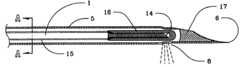
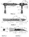
- FIG. 1is a side elevational view of a device of the present invention
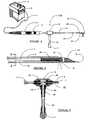
- FIG. 2is an enlarged, partial, cross-sectional, side elevational view of the distal end portion of the optical fiber and the catheter tube of the device of FIG. 1 terminating in a sharp needle end;
- FIG. 3is an enlarged, partial, cross-sectional, side elevational view of the fitting and fluid/vacuum port of the device of FIG. 1 ;
- FIG. 4( a )is an enlarged, cross-sectional view taken along plane A-A in FIG. 2 showing the manner in which a portion of the sheath is flattened to the optical fiber to create passageways between the sheath and the optical fiber;
- FIG. 4( b )is an enlarged cross-sectioned view illustrating an embodiment where the sheath is crimped to the optical fiber so as to create plural passageways;
- FIG. 5is an enlarged, partial cross-sectional, side elevational view of the distal end of the device of FIG. 2 depicting the flow of fluid therethrough;
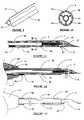
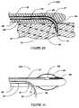
- FIG. 6is an enlarged, partial, cross-sectional, side elevational view of the distal end of the device incorporating the catheter insert of FIGS. 9 and 10 and depicting an alternate fluid flow pattern therethrough;
- FIG. 7is an enlarged, partial, cross-sectional, side elevational view of an alternate embodiment of the handpiece and fluid/vacuum coupling port of the device of the present invention.
- FIG. 8is an enlarged, partial; cross-sectional, side elevational view of another alternate embodiment of the handpiece and fluid/vacuum port of the device of the present invention.
- FIG. 9is a perspective view of a catheter insert for the tube of the device of FIG. 1 ;
- FIG. 10is an enlarged, cross-sectional, side elevational view taken along the plane B-B in FIG. 11 depicting the tubular catheter insert positioned in the interior of the tube of the device of FIG. 11 ;
- FIG. 11is an enlarged, partial, cross-sectional, side elevational view of the distal end of the device incorporating the catheter insert of FIGS. 9 and 10 and depicting one selected fluid flow pattern therethrough;
- FIG. 12is an enlarged, partial, cross-sectional, side elevational view of the device of FIG. 1 with a sleeve surrounding the tube;
- FIG. 13is an enlarged, partial, side elevational view of the device of FIG. 12 ;
- FIG. 14is a enlarged, reduced partial, cross-sectional, side elevational view of the entire device of FIG. 7 , with ports for simultaneous infusion of fluid and drawing of a vacuum operably associated with the handpiece and the fitting, respectively;
- FIG. 15is an enlarged, partial, non-sectional view of device embodying the present invention similar to FIG. 14 and provided with a plastic sheath that extends toward the distal end of the device;
- FIG. 16is an enlarged, partial, cross-sectional view of yet another device embodying the present invention similar to that shown in FIG. 14 but with a different fluid flow pattern;
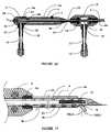
- FIG. 17is an enlarged, partial, cross-sectional, side elevational view of another alternate embodiment of the device of FIG. 1 ;
- FIG. 18is a cross sectional view of an alternate catheter insert embodiment taken along plane C-C in FIG. 19 ;
- FIG. 19is an enlarged, partial, cross-sectional, side elevational view of the distal end of the device of FIG. 1 incorporating the catheter insert embodiment of FIG. 18 ;
- FIG. 20is an enlarged, partial, cross-sectional side elevational view of yet another embodiment of the device of the present invention.
- FIG. 21is an enlarged, partial, cross-sectional, side elevational view of the distal end of the device of FIG. 20 with an inflatable balloon surrounding the distal end;
- FIG. 22is an enlarged, partial, cross-sectional, side elevational view of yet a further embodiment of the device of the present invention and depicting one flow pattern of a fluid therethrough;
- FIG. 23is an enlarged, partial, cross-sectional, side elevational view of an alternate embodiment of the device of FIG. 20 incorporating a catheter insert and depicting an alternate flow pattern of a fluid therethrough;
- FIG. 24is an enlarged, partial, cross-sectional side elevational view of yet another embodiment of the present invention.
- FIG. 25shows yet another device embodying the present invention and provided with a sheath that partially surrounds the catheter tube;
- FIG. 26is an enlarged fragmentary view of the distal end portion of the device depicted in FIG. 25 , partly in section;
- FIG. 27is an enlarged fragmentary sectional view showing a mounting detail of the device depicted in FIG. 25 .
- An apparatus aspect of the present inventionis a medical catheter device for delivering localized energy to a tissue in a patient's body in an amount sufficient to ablate or vaporize the tissue.
- the catheter deviceis suitably positioned within a patient's body by insertion through a body lumen, cavity or surgically created passageway, and advanced to a predetermined site within the body.
- the device of the present inventionis particularly suited for the vaporization of prostate tissue and involves the use of laser energy.
- FIGS. 1-3illustrate one embodiment of a catheter device 100 constructed in accordance with the present invention.
- the device 100incorporates an elongated quartz or fused silica optical fiber 1 extending from a connector 2 which optically couples the optical fiber 1 to a source of laser energy 3 through an elongate tubular handpiece 4 and a hollow elongate generally cylindrically shaped metal tube 5 which extends distally and co-axially from the handpiece 4 .
- a proximal end of tube 5extends at least partially through the handpiece 4 and is secured therein.
- the distal end of tube 5is closed ended and shaped, for example, into a sharp needle point 6 to facilitate the penetration thereof into the area of the tissue to be vaporized.
- Handpiece 4bears a tactile button 7 , located on the side of handpiece 4 opposite the direction of laser beam emission, as shown by the arrows, from a laser emission port or aperture 8 formed in the lower peripheral distal end wall portion of tube 5 .
- a hollow fixture or fitting 9Surrounding and mounted to the proximal end of tube 5 , adjacent the handpiece 4 , is a hollow fixture or fitting 9 which couples the handpiece 4 to tube 5 and, as shown in FIG. 3 , defines an interior cavity 9 a in fluid or gas flow communication with an inlet port or aperture 20 formed in a lower proximal end wall portion of tube 5 .
- the fitting 9has a hollow elongate arm or port 10 depending downwardly therefrom and terminating in a luer lock 11 adapted for connection to a source of fluid or vacuum (not shown).
- Tube 5also includes a fluid outlet port or aperture 12 ( FIG. 1 ) formed in a lower wall portion thereof and positioned approximately 30 cm proximal of the laser energy emission port or aperture 8 thereon.
- Fluid outlet port or aperture 12may be positioned on the same side of the wall of tube 5 as the laser emission port 8 ( FIG. 1 ), or on any other surface of the wall of tube 5 .
- Markings 13 ( FIG. 1 ) on tube 5indicate, for example, in 1 cm or shorter intervals, the distance from laser emission port 8 along the shaft of tube 5 .
- optical fiber 1extends generally longitudinally through the handpiece 4 , the fitting 9 , the interior of tube 5 and terminates in tube 5 at a point opposite and generally aligned vertically with the location of the laser emission port 8 such that the distal end of the fiber 1 is visible through the port 8 .
- the optical fiber 1is spaced from the interior surface of the wall forming tube 5 and thus is spaced and aligned generally parallel to the ports 8 , 12 and 20 formed in tube 5 .
- the distal radial end surface of optical fiber 1has been ground to a flat 30° to 50° angle beveled surface 14 , preferably a surface beveled at an angle of about 40°, which extends angularly inwardly and proximally in the direction of the outlet port 12 ( FIG. 1 ) and facing away from laser emission or lasing port 8 .
- the beveled surface 14allows laser energy emitted from the fiber optic 1 to be directed through the laser emission port 8 at an angle of about 80° to about 90° relative to the longitudinal axis of the fiber optic 1 and tube 5 .
- Optical fiber 1includes a top buffer coat and underlying vinyl cladding 15 which have been removed from the distal end portion thereof to define a bared distal fiber end portion.
- a quartz or fused silica capillary tube 16whose body is hollow and whose distal end is closed ended, is disposed over and surrounds the bared distal end portion of optical fiber 1 , and its proximal end may be affixed to bared optical fiber 1 by thermal fusion or to buffer coat and vinyl cladding 15 thereof by an adhesive.
- capillary tube 16prevents fluid from contacting the beveled distal end surface 14 of optical fiber 1 .
- Tube 5which may be made of medical grade stainless steel such as used in syringe needles may, as described above, have a sharp distal end terminating in the point 6 as shown in FIG. 1 , or a beveled distal end surface terminating in a point, as shown in FIG. 2 , which is common in syringe needles, to facilitate its entry into the tissue.
- the interior of the distal end of rod 5may be filled with an adhesive or other biologically compatible material 17 .
- FIG. 3illustrates the means by which fluid may be infused into the rod 5 to cool the distal end of tube 5 and capillary tube 16 and also to clean any tissue debris from the light emitting quartz or silica surface of capillary tube 16 .
- Fitting 9which includes a hollow interior or cavity 9 a is mounted for rotation about the tube 5 , adjacent the distal end of handpiece 4 . “O” rings 18 create a seal between the hollow interior 9 a and the proximal and distal ends of fitting 9 and tube 5 .
- Fitting 9has a hollow arm or elongate port 10 in fluid communication with an opening or port 19 in the lower wall of the fitting 9 which, in turn, is in fluid flow communication with the co-axially aligned inlet opening or port 20 in tube 5 .
- the arm 10terminates in the standard luer lock 11 , to which a source of fluid, such as a syringe pump, roller pump, syringe or bag of fluid (not shown) may be attached.
- a source of fluidsuch as a syringe pump, roller pump, syringe or bag of fluid (not shown) may be attached.
- a pair of flanges or couplings 21attached to and surrounding the tube 5 , and in turn surrounded by the fitting 9 , prevent fitting 9 from moving longitudinally along tube 5 .
- the “O” rings 18surround the ends of the couplings 21 and contact the interior surface of the wall of the fitting 9 .
- Port 19allows fluid to enter the space 9 a between the lumen of fitting 9 and the exterior of tube 5
- port 20allows fluid to enter the space between the lumen of tube 5 and optical fiber 1 , regardless of the axial position of fitting 9 on tube 5 .
- suctionmay be applied through the arm 10 of FIG. 3 , utilizing a vacuum pump, a syringe or other means (not shown), as known in the art. All references to fluid infusion herein also apply to the use of a vacuum or suction process.
- a plastic tube or hollow rodmay be substituted for metal tube 5 , with a short length of syringe needle attached to its distal end, to facilitate the device's penetration into tissue.
- the distal end of the syringe needleis plugged with an adhesive as described above.
- distal portion of tube 5has, in one embodiment, been flattened to the outer surface of the optical fiber 1 at the 3 o'clock and 9 o'clock positions.
- the inner surface of the wall of the tube 5is forced to contact the outer surface of the fiber 1 and to compress inwardly into an oval or elliptical shape so as to create upper and lower fluid channels or passageways 22 and 23 in the tube 5 .
- FIG. 4( b )which is a cross-section of the device of FIG. 2 , taken through plane A-A, illustrates an embodiment where tube 5 is crimped to the outer surface of fiber 1 , thereby defining a pair of upper fluid channels 22 and a pair of lower fluid channels 23 .
- tube 5is crimped generally from the proximal end of the capillary tube 16 to the proximal end of tube 5 terminating in handpiece 4 .
- channel 22is in fluid flow communication with the channel 23 and the inlet port 20 in tube 5 while the channel 23 is in fluid flow communication with the outlet port 12 in tube 5 .
- Channel 22enables fluid to flow over the distal end of capillary tube 16 so as to cool and clean capillary tube 16 as well as metal tube 5 , to flow into channel 23 and exit therefrom via outlet port 12 in metal tube 5 .
- Fluid channel 23is plugged with adhesive 24 proximal to fluid exit port 12 in the tube 5 , and fluid exit port 12 has a width or diameter greater than the laser emission port 8 in the tube 5 .
- Fluidwill take the path of least resistance in a generally oval shaped pattern, as shown by the clockwise arrows, and flow through fluid channel 22 in the direction of the distal end of the tube 5 , over the top surface of capillary tube 16 , to counter any heat build-up on the top (non-laser emitting side) of capillary tube 16 and tube 5 , then over and around the distal laser emission surface of capillary tube 16 , to cool it and wash away debris, then rearwardly thereof through the lower fluid channel 23 , and then out of the tube 5 through the fluid exit port 12 .
- Adhesive plug 24 in the portion of the channel 23 proximal to port 12prevents and blocks the further rearward flow of the fluid through the tube 5 .
- the adhesiveblocks the flow of fluid through channel 23 upon introduction of the fluid through the inlet port 20 .
- Hot gassescreated by the vaporization of tissue by the laser energy, may also enter laser emission port 8 , travel rearwardly through fluid channel 23 and exit tube 5 through fluid exit port 12 which, as described above, is located at a point remote from the tissue being treated.
- channel 22if negative pressure is applied to channel 22 , fluid is drawn into channel 23 through the port 12 and then flows in and around the capillary tube 16 in a counter-clockwise direction into channel 22 .
- FIG. 7illustrates an alternate embodiment of the handpiece 4 of the device of FIG. 1 where the arm 10 is integrally associated with handpiece 4 rather than fitting 9 ( FIG. 3 ).
- optical fiber 1is affixed to handpiece 4 by adhesive 25 and extends through the handpiece 4 and then tube 5 , whose proximal end portion is affixed to handpiece 4 by adhesive 26 and extends into and through a longitudinal generally cylindrically shaped interior cavity 4 a which extends from the distal end of the handpiece 4 into the body thereof.
- Button 7may be friction fitted into a recess 7 a found in an upper portion of the outer surface of the handpiece 4 or fixed therein by an adhesive.
- the handpiece 4includes a lower threaded aperture 4 b extending between the cavity 4 a and the lower outer surface thereof.
- the arm 10incorporates a threaded coupling 10 a for threadingly engaging threaded aperture 4 b and securing the arm 10 to the handpiece 4 .
- Tube 5is positioned inside the handpiece 4 such that the aperture 20 of tube 5 is positioned generally co-axially opposite and spaced from the aperture 4 b of handpiece 4 .
- fluidmay be infused in a manner similar to that described above with respect to FIG. 5 , through the female luer lock 11 , through arm 10 , through port 19 into cavity 4 a , through opening 20 in tube 5 and then into fluid channel 22 .
- fluidcannot enter lower fluid channel 23 , as it has been occluded distally between the opening 20 and the exit port 12 with adhesive 24 .
- negative pressuremay be applied to luer lock 11 as described above with respect to the FIG. 6 embodiment.
- fitting 9is rotatably attached to the proximal end of handpiece 4 as shown.
- the flange 27 in handpiece 4extends circumferentially outwardly from the distal end portion of handpiece 4 and defines circumferential recess 28 .
- the end portion of the fitting 9is fitted into the recess 28 in the handpiece 4 for coupling the handpiece 4 to the fitting 9 .
- the fitting 9includes a longitudinal central cavity 9 a in communication with a longitudinal central cavity 4 a in the handpiece 4 .
- the tube 5 and optical fiber 1extend through the respective cavities 4 a and 9 a.
- fluidmay be infused through female luer lock 11 , arm 10 , opening 19 in fitting 9 and opening 20 in tube 5 , and into fluid channel 22 (fluid channel 23 having been occluded by adhesive plug 24 in a manner similar to that described above).
- Tube 5is affixed to handpiece 4 by adhesive 26 .
- Gasket 29surrounds the portion of the fiber 1 extending through the proximal end of the fitting 9 and forms a fluid seal to prevent fluid egress from the space between optical fiber 1 and the cavity 9 a in fitting 9 , while permitting fitting 9 to rotate about optical fiber 1 , the proximal end of tube 5 and handpiece 4 .
- handpiece 4 and attached tube 5containing optical fiber 1
- handpiece 4 and attached tube 5can be rotated, without requiring the source of fluid or suction to be likewise rotated, reducing drag in the hand of the operator.
- suctionmay be applied to luer lock 11 .
- the device of the present inventionmay alternatively incorporate a plastic elongated tubular insert 30 , whose inside diameter is only slightly larger than the outside diameter of optical fiber 1 , and is extruded with at least two spaced apart longitudinally extending tines, splines, fins or walls 31 , preferably three tines 31 .
- the insert 30 of FIG. 9may be extruded from materials such as polyvinylchloride (PVC), polyurethane, polypropylene, polyethylene or tetrafluoroethylene, e.g., Teflon®.
- a fluid such as salinemay be infused into fluid inflow channel 22 as described above at a rate of about 1 to 10 cc per minute, preferably about 2 to 6 cc per minute.
- the tines or fins 31extend perpendicularly outwardly from the outer surface of the insert 30 and are spaced around the circumference thereof.
- the tines 31are located generally at the 10 o'clock, 2 o'clock and 6 o'clock positions of insert 30 .
- the optical fiber 1extends through the interior of the insert 30 .
- the optical fiber 1-plastic insert 30 assemblyis disposed within the lumen or interior of tube 5 , with the outer peripheral faces of the tines 31 contacting the inner surface of tube 5 , to form the fluid inflow channel or passageway 22 and two fluid outflow channels or passageways 23 .
- insert 30is positioned generally adjacent the proximal end of capillary tube 16 and aft of the emission port 8 .
- An adhesive or the like 24is used to close both fluid outflow channels 23 aft of the fluid exit port 12 , which adhesive extends rearwardly and terminates just distally of the opening 20 in tube 5 , as shown in FIG. 5 .
- the tines 31are spaced about the outer surface of insert 30 such that the combined area of the lumens of the fluid outflow channels 23 distal to fluid exit port 12 are significantly greater then the area of the lumen of fluid inflow channel 22 .
- fluid exit port 12is larger than laser emission port 8 , creating a path of least resistance for fluid flow and hot gasses flowing out through the fluid exit port 12 .
- fluid from a sourcepasses through fluid channel 22 as shown by the clockwise arrows in FIG. 5 and cools the upper face of the closed distal end portion of capillary tube 16 which encases the distal, beveled end of optical fiber 1 and tube 5 , then passes around, cools and flushes debris from the laser emitting distal end surface of capillary tube 16 , then through the two fluid channels 23 and then exits the device through fluid exit port 12 , outside the area of tissue being treated. As also described above, the fluid cannot proceed further through fluid exit channels 23 due to adhesive 24 , which is disposed therein.
- arrow 32indicates the direction of flow of hot gasses resulting from the vaporization of tissue through laser emission port 8 , into fluid exit channel 23 and then through the exit port 12 .
- the pressure of hot gasses from the vaporization of tissue by laser energyopposes fluid flow through channel 22 and does not permit a substantial amount of the cooling fluid to exit through laser emission port 8 .
- fluid exit port 12is preferably located about 3 to 30 cm, preferably about 4 to 10 cm, proximal and aft of the laser emission port 8 , a distance sufficient to place the fluid exit port 12 outside of the area of the tissue being treated (i.e., outside the body or in the lumen of a vessel, duct, organ or surgically created passage which is being cooled by fluid infused independently through an endoscope or catheter).
- channel 22If a negative pressure is applied to channel 22 , fluid is drawn into port 12 and hot gases from the vaporization of tissue are drawn through laser emission port 8 . Both exit through channel 23 and pass through the handpiece and fitting shown in FIG. 7 into a vacuum collection bottle, syringe or other means, as is known in the art.
- a thin plastic sleeve or sheath 33may be disposed over and surround all but the distal end portion of the tube 5 , to reduce friction with and prevent tissue adherence to the tube 5 .
- the distal end of sleeve 33terminates at a point aft of the laser emission port 8 .
- sleeve 33insulates the tube 5 and prevents heat, conducted along the tube 5 , from coagulating tissue along the puncture channel, causing edema and delaying healing.
- plastic sleeve 33can be fixedly attached to tube 5
- plastic sleeve 33is rotatable about tube 5 and the handpiece 4 .
- the proximal end of plastic sleeve 33has been formed and bent upwardly to form a circumferentially extending flange 34 , which is disposed and fitted within a circumferential recess 35 extending inwardly into the body of the handpiece 4 from the inner surface of the handpiece 4 defining the cavity 4 a therein.
- the flange/recess combinationallows the sleeve 33 to be rotated relative to the handpiece 4 and the tube 5 .
- a port 36 formed in the wall of the plastic sleeve 33is aligned with fluid exit port 12 of tube 5 .
- markings 37 and 38 located at the proximal end outer surfaces of the rod 5 and plastic sleeve 33 respectively,are aligned so as to align the sleeve port 36 with port 12 of tube 5 .
- FIG. 13an external, side view of the device of FIG. 12 , markings 13 on tube 5 , proximal to laser emission port 8 , can be seen through plastic sleeve 33 , enabling an operator to visually (through an endoscope) ascertain the depth to which tube 5 has been inserted into tissue.
- sleeve 33has been rotated 180° over the tube 5 , so that fluid exit port 12 is covered by the sleeve 33 .
- marking 37 on tube 5 and marking 38 on sleeve 33are no longer aligned and are located on opposite sides of the tube 5 .
- the ability to open or close exit port 12 on tube 5 by rotating sleeve 33enables fluid to be infused through fluid inflow channel 22 during all or the first portion of the lasing procedure and, after rotating the plastic sleeve 33 by 90° or more, preferably 180°, permits a vacuum to be drawn during all or the second portion of the lasing procedure and, if desired, afterwards, to collapse the tissue whose inner portion has been vaporized.
- a vacuumcan be drawn through channel 22 during all or the first portion of the lasing procedure to evacuate the hot gasses created by vaporization of tissue and, after rotation of sleeve 33 , fluid to cool the distal end of the device can be infused during all or the second portion of the laser procedure through channel 22 and, if desired, afterwards to cool the tissue.
- the device of FIG. 1may alternatively be configured such that fluid may be infused through the luer lock 11 of a first arm 10 , and suction may be simultaneously applied through a luer lock 11 ′ of a second arm 10 ′.
- the arm 10 with luer lock 11is operably and threadingly associated with the handpiece 4 in the manner as described above with respect to FIG. 8 .
- the second arm 10 ′ with luer lock 11 ′is operably associated with a fitting 9 ′ in the manner described with respect to FIG. 3 above and is mounted fore of the handpiece 4 .
- tube 5 and optical fiber 1extend first through the cavity 9 a defined in the fitting 9 and then through the cavity 4 a defined in the handpiece 4 to define a device incorporating two spaced apart arms 10 and 10 ′.
- the tube 5incorporates a first proximal port 20 in fluid flow communication with the first arm 10 including luer lock 11 and a second distal port 20 ′ in fluid flow communication with the second arm 10 ′ including luer lock 11 ′.
- the portion of the outflow channel 23 extending between the proximal port 20 and the distal port 20 ′has been blocked out or filled with an adhesive 24 .
- there is no fluid exit port in tube 5and fluid is infused in a clockwise direction through the arm 10 with luer lock 11 , then through the various ports and cavities as described above with respect to the other embodiments through the channel 22 and into and around the distal end portion of the capillary tube 16 as also described above to cool the tip.
- the fluid and hot gasses from the vaporization of tissueare then drawn into the channel 23 by a vacuum which can be applied through luer lock 11 ′ and may be deposited in a vacuum collection bottle, a syringe or other device operably associated with the luer lock 11 ′ (not shown), by means known in the art.
- vacuum plus the pressure of gasses formed by the vaporizationcombine to effect faster and more efficient removal of fluid and hot gasses from the tissue opposite laser emission port 8 .
- FIG. 15An alternate, preferred embodiment of the present invention is shown in FIG. 15 .
- the proximal end of plastic sheath 33is fixedly attached within the distal end of the fitting 9 ′ of FIG. 14 by adhesive 29 , and extends toward but stops short of lasing port 8 .
- Sheath 33has at least one port 36 near its proximal end, outside the body. Hot gasses from the vaporization of tissue enter the space 39 between sheath 33 and hollow metal tube 5 , as shown by arrow 39 ( a ), and exit through port 36 in sheath 33 into the atmosphere.
- fluidcan flow through channel 22 , as shown by arrows 31 .
- Negative pressureis applied to channel 23 , and fluid from channel 22 and hot gasses from the vaporization of tissue are drawn into lasing port 8 in metal tube 5 , as shown by arrow 39 ( b ), and pass through channel 23 , as described heretofore.
- FIG. 16A more preferred embodiment of the device of the present invention is shown in FIG. 16 , in which fitting 9 , as shown in FIG. 14 , is used to infuse fluid through channel 22 , created by the space between optical fiber 1 and the interior surface of metal tube 5 .
- adhesive plug 24 shown in FIG. 14is eliminated.
- Fitting 9 ′is rotatably disposed on metal tube 5 .
- “O” ring 18creates a fluid tight seal between fitting 9 ′ and metal tube 5 .
- the proximal end of plastic sleeve or sheath 33is fixedly attached within the distal end of fitting 9 ′ by adhesive 26 .
- Sheath 33in this embodiment, has no ports in its proximal end.
- fluidis infused through fitting 9 into channel 22 , about optical fiber 1 , at a rate of 1 to 10 ml per minute, preferably about 2 to 6 ml per minute.
- Vacuummay be applied through fitting 9 ′ to draw hot gasses from the vaporization of tissue and any fluid not vaporized by the laser energy into the space between tube 5 and the interior of sheath 33 .
- This embodimentis simpler to manufacture and more efficiently removes excess fluid and hot gasses from the vaporization of tissue from the target area.
- a reflector composed of gold, silver, copper or other highly reflective material 40is disposed within the distal end of metal tube 5 , whose distal end has been formed into a sharp point 6 , or into a beveled syringe shape as shown in FIG. 2 .
- the beveled surface 41 of reflective material 40is located opposite and spaced from the distal end of optical fiber 1 and generally above the tube emission port 8 and is inclined at an angle of approximately 35° to 55°, preferably at an angle of about 45°, opposite the end face of optical fiber 1 , to direct the laser energy through the laser emission port 8 at an angle of about 90° relative to the longitudinal axis of the fiber optic 1 and the tube 5 as shown by the dotted lines.
- Such devicesare more fully described in co-owned U.S. Pat. Nos. 5,242,437, 5,380,317 and 5,649,924, which are fully incorporated herein by reference.
- Silveris a preferred reflective material, as it is about as efficient a reflector of holmium laser energy as gold or copper, but is significantly less costly than gold and more durable than copper.
- Tube 5has been crimped to optical fiber 1 , as described in FIG. 4( a ), creating channel 22 and channel 23 .
- a fluidsuch as saline or distilled water, may be infused through channel 22 in a similar manner as described above with respect to FIGS. 3 and 5 in a clockwise direction around the distal end of the fiber optic 1 at a rate of about 1 to 10 cc per minute, preferably about 2 to 4 cc per minute, to wash any debris from the surface 41 of reflective material 40 and the tip of the optical fiber 1 .
- Channels 23enables hot gasses and steam from the vaporization of tissue and cooling fluid to escape through the exit port 12 of tube 5 .
- a vacuummay be drawn through channel 23 in the same manner as described above with respect to FIG. 6 to remove steam and hot gasses and prevent excessive coagulation of the target tissue and coagulation of tissue along the puncture channel.
- the device of FIG. 17may be constructed to incorporate any of the previously described handpiece or fitting or sheath embodiments.
- devices with a gold, silver or copper reflective material 40exhibited a transmission efficiency of approximately 95% compared to a transmission efficiency of approximately 90% for devices with an optical fiber whose distal end is beveled at an angle of about 39° to about 40° and encased in a capillary tube, as described above.
- FIG. 18is a cross-sectional view of the device of FIG. 19 , taken through plane C-C of FIG. 19 .
- the insert 30 of the device of the present inventionmay be substituted with an insert 42 which is extruded of a solid plastic material such as described with respect to the tube 30 and includes a central channel or bore 43 ( FIG. 18 ), just slightly larger in diameter than the diameter of the optical fiber 1 which extends therethrough.
- the insert 42additionally includes a separate top arcuate channel or passageway 22 which is formed in the material of the catheter 42 and is spaced from and partially surrounds the channel 43 .
- the catheter 42also includes a bottom arcuate channel or passageway 23 which is also formed in the material of the catheter 42 and also is spaced from and partially surrounds the channel 43 .
- the channel 23is larger in volume than the channel 22 and the channels 22 , 23 and 43 extend the length of the insert 42 .
- Channel 22is in fluid flow communication with a source of fluid.
- Channel 23may be used for fluid outflow as shown by the clockwise arrows or may be in communication with a vacuum or suction source (not shown) both in the same manner as described above.
- fluidflows into channel 22 , as indicated by the clockwise arrows, and flows over and around the distal end and emission surface of capillary tube 16 and into lower channel or channels 23 .
- the arrowsshow the direction of flow of hot gasses from the vaporization of tissue into port 8 , through channel or channels 23 , and then into a collection means (not shown), as described heretofore.
- Plastic insert 42may also be extruded with additional channels for these or other purposes.
- tube 5can also include a tip or distal end portion 5 a which is secured to a body portion 5 b thereof by an overlapping tongue and groove or the like structure 44 associated with the distal end of the body portion 5 b and the proximal end of the distal end portion 5 a.
- FIG. 20illustrates an alternate embodiment of the present invention.
- this embodimentemploys a guide to deflect the distal end of the device at an angle of up to 90° or more into the target tissue in a very small space.
- the device 200incorporates a plastic or metal rod 45 having a central, longitudinally extending channel 46 whose diameter is larger than the outside diameter of optical fiber 48 , which is slidably disposed therein.
- Channel 46transitions into a curved or arcuate channel 47 , which curves toward and terminates outward in an opening 52 formed in the wall of the rod 45 , at a point proximal to the distal closed arcuate end thereof.
- the buffer coating 49 of optical fiber 48terminates about 2 to 10 cm from the distal end of optical fiber 48 , preferably about 3 to 6 cm from its distal end, having been removed therefrom by means known in the art, leaving the glass cladding (not shown) about optical fiber 48 intact.
- a hollow cylinder 50preferably made of a shape memory alloy such as, for example, a superelastic nitinol, such as manufactured by Memry, Inc. of Menlo Park, Calif., which has been heat treated in a bent configuration at an angle up to 90° or more, preferably at least about 30° to 80°, is attached, by crimping or an adhesive, as known in the art, to the bared distal end portion of optical fiber 48 .
- the distal end of hollow cylinder 50may be beveled into a sharp, syringe needle configuration 51 .
- the distal end face of optical fiber 48is preferably positioned within the opening 51 of cylinder 50 .
- hollow cylinder 50While hollow cylinder 50 is confined within channel 46 of rod 45 , the cylinder 50 is constrained from its heat treated, curved shape.
- the distal end portion of hollow cylinder 50containing bared optical fiber 48 , is manually advanced into curved channel 47 and out through the opening 52 in rod 45 , by means located outside the body (not shown), cylinder 50 returns to its heat treated, curved shape, penetrates endothelial surface 53 and enters tissue 54 at a combined angle of up to 90° or more.
- Fluidmay be infused or a suction may be drawn through the space between the exterior surface of optical fiber 48 and the interior surface of hollow cylinder 50 , or the space between the exterior of cylinder 50 and the interior surfaces of channels 46 and 47 .
- a hollow sleeve 55composed of a plastic, such as Teflon®, may extend over the exterior of hollow cylinder 50 .
- Sleeve 55prevents tissue from sticking to the exterior of hollow cylinder 50 , insulates the tissue from heat conducted along cylinder 50 , and enables gasses from the vaporization of tissue to escape through the space between the exterior surface of hollow rod 50 and the interior surface of sleeve 55 , as well as between the tissue and the nonstick exterior of sleeve 55 .
- Such a devicemay be used to emit laser energy into the prostate gland without damaging the male urethra and its underlying supporting tissue, as well as the esophagus in the region of the sphincter, or the female urethra beneath the bladder, without damaging their sensitive endothelial lining.
- RFradio frequency
- the metal electrodesbecome very hot, conduct heat along their length and can damage the delicate endothelial surface of the tissue into which they were inserted, for example, the urethral surface of the prostate, the endothelial surface of the esophagus in the area of the sphincter or the endothelial surface of the female urethra below the bladder.
- Fluid channelsare needed to cool the endothelial surface and temperature sensors at the endothelial surface are needed to sense the temperature and halt the RF procedure if the damage threshold is reached.
- an expensive temperature monitoring, display and control systemis required, which also increases the risk of an electrical or computer malfunction.
- a balloon 56which may be made of a material such as latex, silicone, polyethylene or polyurethane, surrounds the distal end portion of rod 45 , distal and fore of the point at which hollow cylinder 50 , containing optical fiber 48 (not shown), exits the opening 52 in rod 45 .
- Fluidmay be infused as known in the art through an elongate fluid channel 57 formed in and extending through the body of the rod 45 to inflate balloon 56 .
- An opening 59extending between the channel 57 and the side wall of tube 45 allows for fluid communication between the channel 57 and balloon 56 .
- the portion of the channel 57 located fore of the opening 59is filled with an adhesive 58 to prevent the flow of fluid therethrough.
- Balloon 56may be inflated with a liquid such as saline, a radio opaque or ultrasound opaque fluid or a gas, such as air, CO 2 , nitrogen or the like.
- Balloon 56centers and stabilizes rod 45 within the duct, hollow organ, cavity or passageway into which the rod 45 is inserted. If the device is used through the working channel of an endoscope, the location of the balloon 56 fore of the rod opening 52 of rod 45 allows a physician to see hollow cylinder 50 as it exits opening 52 and enters the tissue. Markings 60 located on the exterior of cylinder 50 enable the physician to observe how far cylinder 50 has been inserted into the described tissue.
- While one optical fiber 48 , one hollow cylinder 50 , one channel 46 and one curved channel 47are shown in the rod 45 of FIGS. 20 and 21 , more than one of each of the above can be employed in rod 45 . Also, curved channel 47 can be eliminated, with optical fiber 48 encased in nitinol cylinder 50 exiting channel 46 directly out of the distal end of rod 45 .
- two, three, four or more optical fibers 48may each have their distal ends encased in superelastic hollow nitinol cylinders 50 and each may be manually advanced, together or separately, through channels 46 and 47 and into the target tissue at an angle of up to 90° or more from the axis of rod 45 .
- rod 45can have a diameter of about 2 to 16 mm, preferably about 3 to 12 mm.
- rod 45For use in the male urethra to vaporize tissue in the prostate, rod 45 , containing one optical fiber 48 and cylinder 50 attached thereto, can have a diameter of about 1.5 to 4 mm, preferably about 2 to 3 mm.
- rod 45For use in the female urethra below the bladder to treat female stress incontinence, rod 45 , containing one optical fiber 48 and one cylinder 50 attached thereto, can have a diameter of about 1 to 3 mm, preferably about 1.5 to 2.5 mm.
- cylinder 50may be eliminated and the distal end of optical fiber 1 may be beveled into a sharp point, to enable it to more easily penetrate tissue.
- Optical fiber 1exits curved channel 47 at an angle in the range of about 20° to about 70° from the axis of rod 45 .
- Optical fiber 1can contain markings 60 to enable an operator to ascertain the depth to which fiber 1 has been inserted into tissue. Since optical fibers are not thermal conductors, fluid need not be infused to cool the endothelial surface of the tissue into which the optical fiber 1 has been inserted during lasing.
- FIG. 22Yet another device embodiment 300 of the present invention is shown in FIG. 22 , in which an optical fiber 61 is slidingly disposed within central channel 62 formed in plastic cannula 63 , the distal end of which is beveled, like a syringe needle, to enable it to more easily penetrate tissue.
- a wire 64made preferably of nitinol, extends through central channel 62 of cannula 63 and is affixed, as by adhesive or the like, to the distal end of cannula 63 at joint 65 on the inner surface that defines channel 62 .
- the proximal end of wire 64is attached to a retractable lever or spool within a handpiece (not shown), as known in the art.
- a retractable lever or spoolwithin a handpiece (not shown), as known in the art.
- retracting or winding up wire 64the distal end portion of plastic sheath 63 may be bent or articulated, up to about 90°, as shown.
- optical fiber 61When cannula 63 is inserted into tissue 66 , laser energy can be emitted through optical fiber 61 , or optical fiber 61 can be manually advanced out of cannula 61 a desired distance.
- optical fiber 61is advanced about 2 to about 8 mm into tissue 66 , and laser energy can be emitted forwardly, as shown by the arrows.
- a fluidsuch as saline
- central channel 62may be infused into central channel 62 , as described above.
- the fluidflows, as shown by the arrows, through the space between optical fiber 61 and the inner surface of central channel 62 and cools sensitive endothelial layer 67 of tissue 66 .
- optical fiber 61extends through the central channel 62 of a plastic cannula 63 , the distal end of which has been beveled, like a syringe needle, and which also contains channels 68 and 69 similar in structure to the channels 22 and 23 , respectively, described in FIG. 14 , above.
- a fluidsuch as saline may be infused through the smaller channel 68 to cool the endothelial tissue surface 67 , and a vacuum or suction may be applied to the larger channel 69 to remove hot gasses from the vaporization of tissue, in the same manner as described above.
- wire 64extends from a retracting mechanism in a handpiece (not shown) through the larger channel 69 and is affixed to the distal end of plastic cannula 63 at point 65 on the inner surface of cannula 63 .
- the distal end of plastic cannula 63is bent or articulated as shown in FIG. 23 , enabling cannula 63 , containing optical fiber 61 to enter tissue 66 at an angle approximately perpendicular to endothelial surface 67 of tissue 66 , as described above.
- Optical fiber 61can be advanced out of cannula 63 a desired distance, up to 10 millimeters, into tissue 66 , preferably 2 to 8 millimeters
- tissue 66preferably 2 to 8 millimeters
- laser energyis emitted through the distal end of optical fiber 61 , into tissue 66 as shown by the arrows, a substantial amount of tissue may be vaporized or coagulated while the tissue underlying the endothelial surface 67 is not thermally damaged and the blood supply to the tissue underlying endothelial surface 67 is preserved.
- device 400includes metal or plastic rod 70 , whose distal end 71 is blunt or round ended and which contains inflation channel 72 , which is in fluid communication with port 73 .
- the portion of channel 72 distal to port 73is filled with an adhesive of epoxy 74 .
- the distal end portion of rod 70including port 73 defined therein, is encased within balloon 75 .
- balloon 75When fluid is infused through channel 72 , balloon 75 is inflated to center and stabilize rod 70 within a duct, blood vessel, body cavity or surgically created passageway.
- Rod 70also contains channel 76 , whose distal end portion is curved, preferably at an angle of 10° to 50° and exits rod 70 at opening or port 77 in rod 70 .
- Optical fiber 78which is disposed within metal tube 79 having a sharp distal end 83 , which is like a syringe needle.
- Metal tube 79may be made of medical grade stainless steel, but, is preferably made of a shape-memory, nickel titanium alloy, whose distal end portion has been heat treated into a curved shape, preferably at an angle of about 20° to about 90°.
- Metal tube 79is encased within a thin plastic sheath 80 which is preferably made of a lubricious material such as a fluorocarbon, e.g., a Teflon® material sheath 80 enables tube 79 to more easily penetrate tissue, insulates and prevents heat conduction into tissue and prevents tissue from sticking to metal tube 79 .
- a lubricious materialsuch as a fluorocarbon, e.g., a Teflon® material sheath 80 enables tube 79 to more easily penetrate tissue, insulates and prevents heat conduction into tissue and prevents tissue from sticking to metal tube 79 .
- Optical fiber 78disposed within tube 79 , is movably disposed within channel 76 of rod 70 .
- metal tube 79is straight, as the stiffness of rod 70 exceeds the strength of sheath's curvature.
- tube 79is no longer constrained by rod 70 and returns to its heat treated, curved shape, causing optical fiber 78 to assume the same curvature.
- optical fiber 78 , tube 79 and sheath 80entering tissue 81 at an angle of about 60° to about 110°, preferably about 70° to 90°.
- a vacuummay be drawn through space 82 between optical fiber 78 and tube 79 by connecting the proximal end of tube 79 (not shown) to a vacuum or suction source (not shown), utilizing a fitting such as fitting 9 of FIG. 3 or handpiece 24 of FIG. 16 (not shown).
- optical fiber 78may be fixedly attached within metal tube 79 and may have a flat distal end, so as to emit laser energy forwardly
- optical fiber 78is movably disposed within metal tube 79 and is shown extended distally therefrom.
- the distal end of optical fiber 78may be beveled at an angle of about 30 to 50°, preferably about 39° to about 40°.
- energyis emitted from optical fiber 78 by total internal reflection at an angle of about 70° to about 90° from the axes of optical fiber 78 , as shown by dotted lines 84 .
- optical fiber 78may be rotated to create a larger vaporization zone in tissue 81 .
- a metal or plastic band 85may be attached to the distal end of optical fiber 78 , whose diameter is slightly smaller than the inner diameter of metal tube 79 .
- Band 85when the distal end of optical fiber 78 is positioned within the distal end of metal tube 79 , prevents tissue from entering and clogging space 82 between optical fiber 78 and the interior of metal tube 79 , when metal tube 79 and optical fiber 78 are being inserted into tissue 81 .
- Markings 86 on plastic sheath 80enable the operator to ascertain the depth to which tube 79 , containing optical fiber 78 , has been inserted into tissue 81 .
- distal end of tube 79may be similarly articulated or bent by a wire attached to the distal end of tube 79 and retracted by a ratchet or worm gear mechanism (not shown), as known in the art.
- Catheter device 500includes hollow tube 105 mounted to fitting or housing 109 and extends therefrom. Proximal end of hollow tube 105 also extends through handpiece 104 and is secured therein. The distal end portion of hollow tube 105 terminates in a closed, sharp needle point 106 so as to facilitate penetration thereof into the tissue region to be vaporized. The distal end of hollow tube 105 is closed by an adhesive 117 , e.g., an epoxy adhesive.
- an adhesive 117e.g., an epoxy adhesive.
- Hollow tube 105may be made of stainless steel and defines lasing port 108 in the distal end portion thereof.
- a reflective inner surface 139( FIG. 26 ) is provided within hollow tube 105 in the region opposite lasing port 108 so as to reflect any stray emissions from optical fiber 101 through the lasing port 108 .
- Optical fiber 101having a bared distal end portion 102 is situated within hollow tube 105 .
- the distal radial end surface 114 of optical fiber 101is beveled at an angle of about 40°, the beveled surface 114 facing away from lasing port 108 .
- laser energy emitted from optical fiber 101is directed through lasing port 108 at an angle of about 80° to about 90° relative to the longitudinal axis of optical fiber 101 and hollow tube 105 .
- the bared distal end portion 102 of optical fiber 101is received within a hollow, closed-end capillary tube 116 which is transparent and usually made of quartz or fused silica. Capillary tube 116 prevents fluids from contacting the beveled surface 114 of the optical fiber 101 . An air interface or gap is maintained between surface 114 and capillary tube 116 to provide total internal reflection of the emitted laser beam.
- a relatively thin sheath 133surrounds the hollow tube 105 , particularly the distal end portion of hollow tube 105 up to about lasing port 108 .
- Sheath 133preferably is made of a fluorocarbon material, e.g., Teflon® material, or the like lubricious material to reduce friction and minimize tissue adherence to hollow tube 105 when the catheter device is used.
- Sheath 133can be rotatably or fixedly mounted to housing 109 or to hollow tube 105 .
- Sheath 133is shown in FIG. 27 adhesively secured to hollow tube 105 and to housing 109 by adhesive 190 which can be an epoxy adhesive, and the like.
- Housing 109also defines irrigation chamber 192 in communication with passageway 194 and with channel 123 via fluid port or ports such as slots 196 defined in that portion of tube 105 that traverses irrigation chamber 192 defined in housing 109 .
- Lasers which may be used with the deviceinclude argon, KTP, Nd:YAG, diode and others. However, these lasers, if fired at 60 watts for 30 seconds at each of 2, 4, 6 and 8 o'clock, create a large coagulation zone (up to 1.5 cm in depth) and little vaporization. Excimer lasers are efficient vaporizers, but are expensive and of limited power. Pulsed Alexandrite lasers, emitting at about 755 nm, modified Nd:YAG lasers emitting at about 1440 nm and holmium:YAG lasers emitting at about 2100 nm, are preferred for vaporization of tissue, with holmium:YAG being most preferred.
- the optical fibershould be made of quartz or fused silica with a low hydroxyl (—OH) content. If an excimer laser is to be used, the optical fiber should be made of quartz or fused silica with a high hydroxyl (—OH) content.
- Optical fibers which can be used in the device of the present inventioncan have a core diameter of about 200 to 1,000 microns, preferably about 300 to 600 microns.
- the devices of FIGS. 1-19 or FIGS. 24-27may be inserted into a lobe of an average sized (30 to 40 gram) prostate, with its distal end always at least 0.5 cm beneath the surface, and oriented to fire away from the urethra.
- a holmium:YAG lasergenerating 60 watts of power (3 joules per pulse at a repetition rate of 20 pulses per second) for five to sixty seconds, preferably about ten to forty seconds, may be used with constant (saline) flow of about 2 to 6 cc per minute, while rotating the tip of the device through a 90° arc at one or more points about 1 cm apart within the lobes of the prostate (from the veru montaneum to the bladder neck).
- the devicemay be rotated through a 90° arc at a rate, for example, of about 90° per second, or advanced and withdrawn while lasing within the lobe at a rate of about 1 cm per second.
- the metal tubemay be first inserted, for example, in the left lobe of the prostate at 2 o'clock and the above described lasing procedures performed. The metal tube insertion and lasing procedures would then be repeated at 4 o'clock in the same lobe, at 8 and 10 o'clock in the right lobe and, if desired, at 6 or 5 and 7 o'clock in the median lobe, if it is significantly enlarged.
- the method of use of such devicesis described in co-owned U.S. Pat. No. 5,437,660, incorporated herein by reference.
- a Holmium laserwill produce a vaporization zone in tissue of about one cm in diameter in each lasing position. If there are a total of 12 lasing positions, approximately 12 cc of tissue will be vaporized with minimal coagulation of tissue.
- Lower powerfor example 30 watts of Holmium:YAG laser energy (2 joules per pulse at a repetition rate of 15 pulses per second) may be employed for about 30 seconds to about 1 minute at each lasing position, for example with the device inserted at 2, 4, 8, 10 o'clock for an average sized prostate, and at 6 or 5 and 7 o'clock if the median lobe is enlarged.
- the devices of FIGS. 20-23may be inserted to a depth of at least 0.5 cm into a lobe of the prostate and a similar amount of laser energy may be emitted. The procedure may then be repeated at about 1 cm intervals from the earlier puncture and lasing sites.
- Excimer or holmium:YAG lasersare preferred. If it is desired to coagulate the tumor in situ, an argon, KTP, diode or Nd:YAG laser may be used.
- the side firing devices of FIGS. 1-19 and FIGS. 24-27may be inserted into the center of the tumor if it is spherical, and energy may be emitted, for example, at a given level for the same amount of time at 3, 6, 9 and 12 o'clock.
- energymay be emitted, for example at a given level of energy at 6 and 12 o'clock for 30 seconds, and at 3 and 9 o'clock for 15 seconds, producing an oval coagulation and/or vaporization zone.
- a given level of energymay be emitted for the same amount of time at 2, 4, 8 and 10 o'clock.
- the devicemay be inserted at two or more points and fired, for example, at a given amount of energy for the same or a different amount of time in directions necessary to assure complete coagulation or vaporization of the tumor.
- the devicemay be inserted between the blood vessel, duct, nerve or structure and fired away therefrom in one or more directions. In any case, if a shallower depth of vaporization or coagulation is desired, the amount of energy and/or the amount of time may be varied.
Landscapes
- Health & Medical Sciences (AREA)
- Surgery (AREA)
- Physics & Mathematics (AREA)
- Life Sciences & Earth Sciences (AREA)
- Engineering & Computer Science (AREA)
- Medical Informatics (AREA)
- Nuclear Medicine, Radiotherapy & Molecular Imaging (AREA)
- Electromagnetism (AREA)
- Optics & Photonics (AREA)
- Biomedical Technology (AREA)
- Heart & Thoracic Surgery (AREA)
- Otolaryngology (AREA)
- Molecular Biology (AREA)
- Animal Behavior & Ethology (AREA)
- General Health & Medical Sciences (AREA)
- Public Health (AREA)
- Veterinary Medicine (AREA)
- Laser Surgery Devices (AREA)
Abstract
Description
Claims (6)
Priority Applications (1)
| Application Number | Priority Date | Filing Date | Title |
|---|---|---|---|
| US10/963,213US7306588B2 (en) | 2002-04-22 | 2004-10-12 | Devices and methods for directed, interstitial ablation of tissue |
Applications Claiming Priority (2)
| Application Number | Priority Date | Filing Date | Title |
|---|---|---|---|
| US10/127,382US6802838B2 (en) | 2002-04-22 | 2002-04-22 | Devices and methods for directed, interstitial ablation of tissue |
| US10/963,213US7306588B2 (en) | 2002-04-22 | 2004-10-12 | Devices and methods for directed, interstitial ablation of tissue |
Related Parent Applications (1)
| Application Number | Title | Priority Date | Filing Date |
|---|---|---|---|
| US10/127,382Continuation-In-PartUS6802838B2 (en) | 2002-04-22 | 2002-04-22 | Devices and methods for directed, interstitial ablation of tissue |
Publications (2)
| Publication Number | Publication Date |
|---|---|
| US20050131399A1 US20050131399A1 (en) | 2005-06-16 |
| US7306588B2true US7306588B2 (en) | 2007-12-11 |
Family
ID=46303066
Family Applications (1)
| Application Number | Title | Priority Date | Filing Date |
|---|---|---|---|
| US10/963,213Expired - Fee RelatedUS7306588B2 (en) | 2002-04-22 | 2004-10-12 | Devices and methods for directed, interstitial ablation of tissue |
Country Status (1)
| Country | Link |
|---|---|
| US (1) | US7306588B2 (en) |
Cited By (61)
| Publication number | Priority date | Publication date | Assignee | Title |
|---|---|---|---|---|
| US20090287197A1 (en)* | 2008-05-19 | 2009-11-19 | Hanley Brian M | Side-firing laser fiber with internal bent fiber and related methods |
| US20090326525A1 (en)* | 2008-06-26 | 2009-12-31 | Jessica Hixon | Laser fiber capillary apparatus and method |
| US20110118715A1 (en)* | 2009-11-18 | 2011-05-19 | Zerfas Jeffrey W | Methods and apparatus related to a side-fire assembly that has an optical grating |
| WO2011085299A2 (en) | 2010-01-08 | 2011-07-14 | Ceramoptec Industries, Inc. | Device and method for underskin radiation treatment of adipose tissue |
| WO2011034938A3 (en)* | 2009-09-15 | 2011-07-14 | Ceramoptec Industries, Inc. | Ablative/coagulative urological treatment device and method |
| US20120303131A1 (en)* | 2009-12-11 | 2012-11-29 | Gursharan Singh Chana | Surgical apparatus |
| WO2013043396A1 (en)* | 2011-09-23 | 2013-03-28 | Alcon Research, Ltd. | Ophthalmic endoilluminators with directed light |
| US20130231648A1 (en)* | 2008-05-19 | 2013-09-05 | Boston Scientific Scimed, Inc. | Method and apparatus for protecting capillary of laser fiber during insertion and reducing metal cap degradation |
| ES2472542A1 (en)* | 2012-12-31 | 2014-07-01 | Universidad De Granada | Directional tissue ablation device |
| US8926502B2 (en) | 2011-03-07 | 2015-01-06 | Endochoice, Inc. | Multi camera endoscope having a side service channel |
| US8961551B2 (en) | 2006-12-22 | 2015-02-24 | The Spectranetics Corporation | Retractable separating systems and methods |
| US9028520B2 (en) | 2006-12-22 | 2015-05-12 | The Spectranetics Corporation | Tissue separating systems and methods |
| US9101287B2 (en) | 2011-03-07 | 2015-08-11 | Endochoice Innovation Center Ltd. | Multi camera endoscope assembly having multiple working channels |
| US9101268B2 (en) | 2009-06-18 | 2015-08-11 | Endochoice Innovation Center Ltd. | Multi-camera endoscope |
| US9101266B2 (en) | 2011-02-07 | 2015-08-11 | Endochoice Innovation Center Ltd. | Multi-element cover for a multi-camera endoscope |
| US9283040B2 (en) | 2013-03-13 | 2016-03-15 | The Spectranetics Corporation | Device and method of ablative cutting with helical tip |
| US9291663B2 (en) | 2013-03-13 | 2016-03-22 | The Spectranetics Corporation | Alarm for lead insulation abnormality |
| US9314147B2 (en) | 2011-12-13 | 2016-04-19 | Endochoice Innovation Center Ltd. | Rotatable connector for an endoscope |
| US9320419B2 (en) | 2010-12-09 | 2016-04-26 | Endochoice Innovation Center Ltd. | Fluid channeling component of a multi-camera endoscope |
| US9402533B2 (en) | 2011-03-07 | 2016-08-02 | Endochoice Innovation Center Ltd. | Endoscope circuit board assembly |
| US9413896B2 (en) | 2012-09-14 | 2016-08-09 | The Spectranetics Corporation | Tissue slitting methods and systems |
| USD765243S1 (en) | 2015-02-20 | 2016-08-30 | The Spectranetics Corporation | Medical device handle |
| US9456872B2 (en) | 2013-03-13 | 2016-10-04 | The Spectranetics Corporation | Laser ablation catheter |
| USD770616S1 (en) | 2015-02-20 | 2016-11-01 | The Spectranetics Corporation | Medical device handle |
| US9492063B2 (en) | 2009-06-18 | 2016-11-15 | Endochoice Innovation Center Ltd. | Multi-viewing element endoscope |
| US9554692B2 (en) | 2009-06-18 | 2017-01-31 | EndoChoice Innovation Ctr. Ltd. | Multi-camera endoscope |
| US9560954B2 (en) | 2012-07-24 | 2017-02-07 | Endochoice, Inc. | Connector for use with endoscope |
| US9560953B2 (en) | 2010-09-20 | 2017-02-07 | Endochoice, Inc. | Operational interface in a multi-viewing element endoscope |
| US9603618B2 (en) | 2013-03-15 | 2017-03-28 | The Spectranetics Corporation | Medical device for removing an implanted object |
| US9642513B2 (en) | 2009-06-18 | 2017-05-09 | Endochoice Inc. | Compact multi-viewing element endoscope system |
| US9655502B2 (en) | 2011-12-13 | 2017-05-23 | EndoChoice Innovation Center, Ltd. | Removable tip endoscope |
| US9668765B2 (en) | 2013-03-15 | 2017-06-06 | The Spectranetics Corporation | Retractable blade for lead removal device |
| US9706903B2 (en) | 2009-06-18 | 2017-07-18 | Endochoice, Inc. | Multiple viewing elements endoscope system with modular imaging units |
| US9713417B2 (en) | 2009-06-18 | 2017-07-25 | Endochoice, Inc. | Image capture assembly for use in a multi-viewing elements endoscope |
| US9814374B2 (en) | 2010-12-09 | 2017-11-14 | Endochoice Innovation Center Ltd. | Flexible electronic circuit board for a multi-camera endoscope |
| US9872609B2 (en) | 2009-06-18 | 2018-01-23 | Endochoice Innovation Center Ltd. | Multi-camera endoscope |
| US9883885B2 (en) | 2013-03-13 | 2018-02-06 | The Spectranetics Corporation | System and method of ablative cutting and pulsed vacuum aspiration |
| US9901244B2 (en) | 2009-06-18 | 2018-02-27 | Endochoice, Inc. | Circuit board assembly of a multiple viewing elements endoscope |
| US9925366B2 (en) | 2013-03-15 | 2018-03-27 | The Spectranetics Corporation | Surgical instrument for removing an implanted object |
| US9980743B2 (en) | 2013-03-15 | 2018-05-29 | The Spectranetics Corporation | Medical device for removing an implanted object using laser cut hypotubes |
| US9986899B2 (en) | 2013-03-28 | 2018-06-05 | Endochoice, Inc. | Manifold for a multiple viewing elements endoscope |
| US9993142B2 (en) | 2013-03-28 | 2018-06-12 | Endochoice, Inc. | Fluid distribution device for a multiple viewing elements endoscope |
| US10080486B2 (en) | 2010-09-20 | 2018-09-25 | Endochoice Innovation Center Ltd. | Multi-camera endoscope having fluid channels |
| US10136913B2 (en) | 2013-03-15 | 2018-11-27 | The Spectranetics Corporation | Multiple configuration surgical cutting device |
| US10165929B2 (en) | 2009-06-18 | 2019-01-01 | Endochoice, Inc. | Compact multi-viewing element endoscope system |
| US10203493B2 (en) | 2010-10-28 | 2019-02-12 | Endochoice Innovation Center Ltd. | Optical systems for multi-sensor endoscopes |
| US10383691B2 (en) | 2013-03-13 | 2019-08-20 | The Spectranetics Corporation | Last catheter with helical internal lumen |
| US10405924B2 (en) | 2014-05-30 | 2019-09-10 | The Spectranetics Corporation | System and method of ablative cutting and vacuum aspiration through primary orifice and auxiliary side port |
| US10448999B2 (en) | 2013-03-15 | 2019-10-22 | The Spectranetics Corporation | Surgical instrument for removing an implanted object |
| US10499794B2 (en) | 2013-05-09 | 2019-12-10 | Endochoice, Inc. | Operational interface in a multi-viewing element endoscope |
| US10835279B2 (en) | 2013-03-14 | 2020-11-17 | Spectranetics Llc | Distal end supported tissue slitting apparatus |
| US10842532B2 (en) | 2013-03-15 | 2020-11-24 | Spectranetics Llc | Medical device for removing an implanted object |
| US10856940B2 (en) | 2016-03-02 | 2020-12-08 | Covidien Lp | Ablation antenna including customizable reflectors |
| US11278190B2 (en) | 2009-06-18 | 2022-03-22 | Endochoice, Inc. | Multi-viewing element endoscope |
| US11547275B2 (en) | 2009-06-18 | 2023-01-10 | Endochoice, Inc. | Compact multi-viewing element endoscope system |
| US11864734B2 (en) | 2009-06-18 | 2024-01-09 | Endochoice, Inc. | Multi-camera endoscope |
| US11889986B2 (en) | 2010-12-09 | 2024-02-06 | Endochoice, Inc. | Flexible electronic circuit board for a multi-camera endoscope |
| US12053203B2 (en) | 2014-03-03 | 2024-08-06 | Spectranetics, Llc | Multiple configuration surgical cutting device |
| US12137873B2 (en) | 2009-06-18 | 2024-11-12 | Endochoice, Inc. | Compact multi-viewing element endoscope system |
| US12204087B2 (en) | 2010-10-28 | 2025-01-21 | Endochoice, Inc. | Optical systems for multi-sensor endoscopes |
| US12220105B2 (en) | 2010-06-16 | 2025-02-11 | Endochoice, Inc. | Circuit board assembly of a multiple viewing elements endoscope |
Families Citing this family (48)
| Publication number | Priority date | Publication date | Assignee | Title |
|---|---|---|---|---|
| US7588581B2 (en)* | 2002-03-26 | 2009-09-15 | Medtronic, Inc. | Placement of chronic micro-catheter device and method |
| US7270656B2 (en)* | 2003-11-07 | 2007-09-18 | Visualase, Inc. | Cooled laser fiber for improved thermal therapy |
| US8346346B1 (en) | 2005-01-24 | 2013-01-01 | The Board Of Trustees Of The Leland Stanford Junior University | Optical analysis system and approach therefor |
| CA2629440A1 (en)* | 2005-11-10 | 2007-05-18 | Allegiance Corporation | Multifunctional medical device assembly |
| AU2007212089B2 (en)* | 2006-02-07 | 2010-04-22 | Ams Research Corporation | Laparoscopic laser device and method |
| ES2469593T3 (en)* | 2006-03-13 | 2014-06-18 | Bruno Anastasie | Laser instrument, applicable to vascular occlusion particularly for intravenous treatment as well as perforation or tissue detersion |
| US20100241111A1 (en)* | 2006-07-04 | 2010-09-23 | Bracco Imaging S.P.A. | Device for localized thermal ablation of biological tissues, particularly tumoral tissues or the like |
| US12290277B2 (en) | 2007-01-02 | 2025-05-06 | Aquabeam, Llc | Tissue resection with pressure sensing |
| US9403029B2 (en) | 2007-07-18 | 2016-08-02 | Visualase, Inc. | Systems and methods for thermal therapy |
| US20090125014A1 (en)* | 2007-11-14 | 2009-05-14 | Bouthillier Robert J | Thermal Ablation System |
| WO2009108933A2 (en)* | 2008-02-28 | 2009-09-03 | Palomar Medical Technologies, Inc. | Systems and methods for treatment of soft tissue |
| ES2769535T3 (en) | 2008-03-06 | 2020-06-26 | Aquabeam Llc | Tissue ablation and cauterization with optical energy carried in a fluid stream |
| WO2010100573A1 (en)* | 2009-03-02 | 2010-09-10 | Koninklijke Philips Electronics, N.V. | Transurethral ultrasound probe for treatment of prostate |
| US8721631B2 (en)* | 2009-09-24 | 2014-05-13 | Biolite Pharma Marketing Ltd | Twister fiber optic systems and their use in medical applications |
| US8840605B2 (en) | 2011-09-02 | 2014-09-23 | Katalyst Surgical, Llc | Steerable laser probe |
| US9138350B2 (en) | 2011-10-17 | 2015-09-22 | Katalyst Surgical, Llc | Steerable laser probe |
| US9107682B2 (en) | 2011-11-03 | 2015-08-18 | Katalyst Surgical, Llc | Steerable laser probe |
| US10213260B2 (en)* | 2011-12-01 | 2019-02-26 | Joe Denton Brown | End fire fiber arrangements with improved erosion resistance |
| US8840607B2 (en) | 2011-12-23 | 2014-09-23 | Katalyst Surgical, Llc | Steerable laser probe |
| US9113995B2 (en)* | 2012-05-08 | 2015-08-25 | Katalyst Surgical, Llc | Steerable laser probe |
| US8951245B2 (en) | 2012-05-09 | 2015-02-10 | Katalyst Surgical, Llc | Steerable laser probe |
| US9770296B2 (en) | 2012-07-31 | 2017-09-26 | Katalyst Surgical, Llc | Steerable laser probe |
| US9770298B2 (en) | 2012-08-10 | 2017-09-26 | Katalyst Surgical, Llc | Steerable laser probe |
| US9216060B2 (en) | 2012-08-14 | 2015-12-22 | Katalyst Surgical, Llc | Steerable laser probe |
| US9232975B2 (en) | 2012-09-05 | 2016-01-12 | Katalyst Surgical, Llc | Steerable laser probe |
| US9226855B2 (en) | 2012-09-06 | 2016-01-05 | Katalyst Surgical, Llc | Steerable laser probe |
| US9351875B2 (en) | 2012-09-12 | 2016-05-31 | Katalyst Surgical, Llc | Steerable laser probe |
| US9226794B2 (en) | 2012-09-23 | 2016-01-05 | Katalyst Surgical, Llc | Steerable laser probe |
| US9216111B2 (en) | 2012-09-24 | 2015-12-22 | Katalyst Surgical, Llc | Steerable laser probe |
| CN103222895B (en)* | 2012-10-12 | 2016-02-03 | 上海菲捷实业有限公司 | A kind of heat abstractor for laser therapy |
| US9763830B2 (en) | 2012-10-13 | 2017-09-19 | Katalyst Surgical, Llc | Steerable laser probe |
| CN103169444A (en)* | 2013-04-02 | 2013-06-26 | 夏永强 | Laser fiber guiding and water absorption tube used for nephroscope |
| CN110420057B (en)* | 2013-10-15 | 2022-10-14 | 尼普洛株式会社 | Ablation system and ablation device |
| CN105636540B (en) | 2013-10-15 | 2019-10-18 | 尼普洛株式会社 | Ablation system and ablation equipment |
| US11399892B2 (en) | 2015-03-19 | 2022-08-02 | Boston Scientific Scimed, Inc. | Side-fire laser fiber having a molded reflective surface |
| US10695128B2 (en)* | 2015-04-16 | 2020-06-30 | Boston Scientific Scimed, Inc. | Methods and devices for targeted ablation of tissue |
| US10245182B2 (en) | 2015-11-14 | 2019-04-02 | Katalyst Surgical, Llc | Laser probe with replaceable optic fibers |
| US11172988B2 (en) | 2016-01-27 | 2021-11-16 | Optical Integrity, Inc. | End fire fiber arrangements with improved erosion resistance |
| US11172821B2 (en) | 2016-04-28 | 2021-11-16 | Medtronic Navigation, Inc. | Navigation and local thermometry |
| US10420460B2 (en) | 2016-09-09 | 2019-09-24 | Katalyst Surgical, Llc | Illumination probe |
| US10646113B2 (en) | 2016-09-09 | 2020-05-12 | Katalyst Surgical, Llc | Illuminated cannula |
| US10709504B2 (en) | 2016-09-19 | 2020-07-14 | Katalyst Surgical, Llc | Curved laser probe with single-use optic fiber |
| US10052169B2 (en)* | 2016-11-03 | 2018-08-21 | Meshil A. M. O. H. Al-Jarba | Shield for electrosurgical suction coagulator and kit including the same |
| WO2018118987A1 (en)* | 2016-12-20 | 2018-06-28 | Boston Scientific Scimed, Inc. | Fluid cooled optical fiber |
| GB2565573A (en) | 2017-08-17 | 2019-02-20 | Creo Medical Ltd | Interface joint for an electrosurgical apparatus |
| AU2019458295B2 (en)* | 2019-07-24 | 2025-02-27 | Medlogical Innovations Pty Ltd | System with cooling fluid for interstitial laser therapy |
| WO2022130362A1 (en)* | 2020-12-20 | 2022-06-23 | Lumenis Ltd | Apparatus for laser morcellation |
| WO2022181133A1 (en)* | 2021-02-25 | 2022-09-01 | 株式会社カネカ | Light irradiation device for endoscope |
Citations (4)
| Publication number | Priority date | Publication date | Assignee | Title |
|---|---|---|---|---|
| US5304171A (en)* | 1990-10-18 | 1994-04-19 | Gregory Kenton W | Catheter devices and methods for delivering |
| US5454807A (en)* | 1993-05-14 | 1995-10-03 | Boston Scientific Corporation | Medical treatment of deeply seated tissue using optical radiation |
| US5649924A (en)* | 1988-06-10 | 1997-07-22 | Trimedyne, Inc. | Medical device for irradiation of tissue |
| US6520927B1 (en)* | 2000-01-14 | 2003-02-18 | John D. Unsworth | Method and device to prevent cardiac dysrhythmias |
- 2004
- 2004-10-12USUS10/963,213patent/US7306588B2/ennot_activeExpired - Fee Related
Patent Citations (4)
| Publication number | Priority date | Publication date | Assignee | Title |
|---|---|---|---|---|
| US5649924A (en)* | 1988-06-10 | 1997-07-22 | Trimedyne, Inc. | Medical device for irradiation of tissue |
| US5304171A (en)* | 1990-10-18 | 1994-04-19 | Gregory Kenton W | Catheter devices and methods for delivering |
| US5454807A (en)* | 1993-05-14 | 1995-10-03 | Boston Scientific Corporation | Medical treatment of deeply seated tissue using optical radiation |
| US6520927B1 (en)* | 2000-01-14 | 2003-02-18 | John D. Unsworth | Method and device to prevent cardiac dysrhythmias |
Cited By (139)
| Publication number | Priority date | Publication date | Assignee | Title |
|---|---|---|---|---|
| US10537354B2 (en) | 2006-12-22 | 2020-01-21 | The Spectranetics Corporation | Retractable separating systems and methods |
| US10869687B2 (en) | 2006-12-22 | 2020-12-22 | Spectranetics Llc | Tissue separating systems and methods |
| US9808275B2 (en) | 2006-12-22 | 2017-11-07 | The Spectranetics Corporation | Retractable separating systems and methods |
| US9801650B2 (en) | 2006-12-22 | 2017-10-31 | The Spectranetics Corporation | Tissue separating systems and methods |
| US9289226B2 (en) | 2006-12-22 | 2016-03-22 | The Spectranetics Corporation | Retractable separating systems and methods |
| US9028520B2 (en) | 2006-12-22 | 2015-05-12 | The Spectranetics Corporation | Tissue separating systems and methods |
| US8961551B2 (en) | 2006-12-22 | 2015-02-24 | The Spectranetics Corporation | Retractable separating systems and methods |
| US8657812B2 (en)* | 2008-05-19 | 2014-02-25 | Boston Scientific Scimed, Inc. | Side-firing laser fiber with internal bent fiber and related methods |
| US20090287197A1 (en)* | 2008-05-19 | 2009-11-19 | Hanley Brian M | Side-firing laser fiber with internal bent fiber and related methods |
| US9050118B2 (en)* | 2008-05-19 | 2015-06-09 | Boston Scientific Scimed, Inc. | Method and apparatus for protecting capillary of laser fiber during insertion and reducing metal cap degradation |
| US20130231648A1 (en)* | 2008-05-19 | 2013-09-05 | Boston Scientific Scimed, Inc. | Method and apparatus for protecting capillary of laser fiber during insertion and reducing metal cap degradation |
| US20090326525A1 (en)* | 2008-06-26 | 2009-12-31 | Jessica Hixon | Laser fiber capillary apparatus and method |
| US9901244B2 (en) | 2009-06-18 | 2018-02-27 | Endochoice, Inc. | Circuit board assembly of a multiple viewing elements endoscope |
| US12137873B2 (en) | 2009-06-18 | 2024-11-12 | Endochoice, Inc. | Compact multi-viewing element endoscope system |
| US9872609B2 (en) | 2009-06-18 | 2018-01-23 | Endochoice Innovation Center Ltd. | Multi-camera endoscope |
| US12336686B2 (en) | 2009-06-18 | 2025-06-24 | Endochoice, Inc. | Multi-viewing element endoscope |
| US11547275B2 (en) | 2009-06-18 | 2023-01-10 | Endochoice, Inc. | Compact multi-viewing element endoscope system |
| US10638922B2 (en) | 2009-06-18 | 2020-05-05 | Endochoice, Inc. | Multi-camera endoscope |
| US10765305B2 (en) | 2009-06-18 | 2020-09-08 | Endochoice, Inc. | Circuit board assembly of a multiple viewing elements endoscope |
| US11864734B2 (en) | 2009-06-18 | 2024-01-09 | Endochoice, Inc. | Multi-camera endoscope |
| US9713417B2 (en) | 2009-06-18 | 2017-07-25 | Endochoice, Inc. | Image capture assembly for use in a multi-viewing elements endoscope |
| US11471028B2 (en) | 2009-06-18 | 2022-10-18 | Endochoice, Inc. | Circuit board assembly of a multiple viewing elements endoscope |
| US10165929B2 (en) | 2009-06-18 | 2019-01-01 | Endochoice, Inc. | Compact multi-viewing element endoscope system |
| US10791910B2 (en) | 2009-06-18 | 2020-10-06 | Endochoice, Inc. | Multiple viewing elements endoscope system with modular imaging units |
| US9101268B2 (en) | 2009-06-18 | 2015-08-11 | Endochoice Innovation Center Ltd. | Multi-camera endoscope |
| US10092167B2 (en) | 2009-06-18 | 2018-10-09 | Endochoice, Inc. | Multiple viewing elements endoscope system with modular imaging units |
| US12303106B2 (en) | 2009-06-18 | 2025-05-20 | Endochoice, Inc. | Multi-camera endoscope |
| US9706905B2 (en) | 2009-06-18 | 2017-07-18 | Endochoice Innovation Center Ltd. | Multi-camera endoscope |
| US9706903B2 (en) | 2009-06-18 | 2017-07-18 | Endochoice, Inc. | Multiple viewing elements endoscope system with modular imaging units |
| US10791909B2 (en) | 2009-06-18 | 2020-10-06 | Endochoice, Inc. | Image capture assembly for use in a multi-viewing elements endoscope |
| US11278190B2 (en) | 2009-06-18 | 2022-03-22 | Endochoice, Inc. | Multi-viewing element endoscope |
| US10799095B2 (en) | 2009-06-18 | 2020-10-13 | Endochoice, Inc. | Multi-viewing element endoscope |
| US10912445B2 (en) | 2009-06-18 | 2021-02-09 | Endochoice, Inc. | Compact multi-viewing element endoscope system |
| US9642513B2 (en) | 2009-06-18 | 2017-05-09 | Endochoice Inc. | Compact multi-viewing element endoscope system |
| US11986155B2 (en) | 2009-06-18 | 2024-05-21 | Endochoice, Inc. | Multi-viewing element endoscope |
| US10905320B2 (en) | 2009-06-18 | 2021-02-02 | Endochoice, Inc. | Multi-camera endoscope |
| US9554692B2 (en) | 2009-06-18 | 2017-01-31 | EndoChoice Innovation Ctr. Ltd. | Multi-camera endoscope |
| US11534056B2 (en) | 2009-06-18 | 2022-12-27 | Endochoice, Inc. | Multi-camera endoscope |
| US9492063B2 (en) | 2009-06-18 | 2016-11-15 | Endochoice Innovation Center Ltd. | Multi-viewing element endoscope |
| WO2011034938A3 (en)* | 2009-09-15 | 2011-07-14 | Ceramoptec Industries, Inc. | Ablative/coagulative urological treatment device and method |
| US20110196356A1 (en)* | 2009-09-15 | 2011-08-11 | Ceramoptec Industries Inc. | Ablative/coagulative urological treatment device and method |
| US20110118715A1 (en)* | 2009-11-18 | 2011-05-19 | Zerfas Jeffrey W | Methods and apparatus related to a side-fire assembly that has an optical grating |
| US9788898B2 (en) | 2009-11-18 | 2017-10-17 | Boston Scientific Scimed, Inc. | Methods and apparatus related to a side-fire assembly that has an optical grating |
| US8870858B2 (en)* | 2009-11-18 | 2014-10-28 | Boston Scientific Scimed, Inc. | Methods and apparatus related to a side-fire assembly that has an optical grating |
| US20120303131A1 (en)* | 2009-12-11 | 2012-11-29 | Gursharan Singh Chana | Surgical apparatus |
| EP2521591A4 (en)* | 2010-01-08 | 2013-05-29 | Ceramoptec Gmbh | DEVICE AND METHOD FOR TREATING ADIPOSE TISSUE THROUGH SKIN RADIATION |
| US20110172652A1 (en)* | 2010-01-08 | 2011-07-14 | Ceramoptec Industries Inc. | Method and device for underskin radiation treatment of adipose tissue |
| WO2011085299A2 (en) | 2010-01-08 | 2011-07-14 | Ceramoptec Industries, Inc. | Device and method for underskin radiation treatment of adipose tissue |
| US9788897B2 (en)* | 2010-01-08 | 2017-10-17 | Biolitec Unternehmensbeteiligungs Ii Ag | Method and device for underskin radiation treatment of adipose tissue |
| US12220105B2 (en) | 2010-06-16 | 2025-02-11 | Endochoice, Inc. | Circuit board assembly of a multiple viewing elements endoscope |
| US9986892B2 (en) | 2010-09-20 | 2018-06-05 | Endochoice, Inc. | Operational interface in a multi-viewing element endoscope |
| US10080486B2 (en) | 2010-09-20 | 2018-09-25 | Endochoice Innovation Center Ltd. | Multi-camera endoscope having fluid channels |
| US9560953B2 (en) | 2010-09-20 | 2017-02-07 | Endochoice, Inc. | Operational interface in a multi-viewing element endoscope |
| US10203493B2 (en) | 2010-10-28 | 2019-02-12 | Endochoice Innovation Center Ltd. | Optical systems for multi-sensor endoscopes |
| US11543646B2 (en) | 2010-10-28 | 2023-01-03 | Endochoice, Inc. | Optical systems for multi-sensor endoscopes |
| US12204087B2 (en) | 2010-10-28 | 2025-01-21 | Endochoice, Inc. | Optical systems for multi-sensor endoscopes |
| US10182707B2 (en) | 2010-12-09 | 2019-01-22 | Endochoice Innovation Center Ltd. | Fluid channeling component of a multi-camera endoscope |
| US9320419B2 (en) | 2010-12-09 | 2016-04-26 | Endochoice Innovation Center Ltd. | Fluid channeling component of a multi-camera endoscope |
| US11889986B2 (en) | 2010-12-09 | 2024-02-06 | Endochoice, Inc. | Flexible electronic circuit board for a multi-camera endoscope |
| US10898063B2 (en) | 2010-12-09 | 2021-01-26 | Endochoice, Inc. | Flexible electronic circuit board for a multi camera endoscope |
| US9814374B2 (en) | 2010-12-09 | 2017-11-14 | Endochoice Innovation Center Ltd. | Flexible electronic circuit board for a multi-camera endoscope |
| US11497388B2 (en) | 2010-12-09 | 2022-11-15 | Endochoice, Inc. | Flexible electronic circuit board for a multi-camera endoscope |
| US9351629B2 (en) | 2011-02-07 | 2016-05-31 | Endochoice Innovation Center Ltd. | Multi-element cover for a multi-camera endoscope |
| US9101266B2 (en) | 2011-02-07 | 2015-08-11 | Endochoice Innovation Center Ltd. | Multi-element cover for a multi-camera endoscope |
| US10070774B2 (en) | 2011-02-07 | 2018-09-11 | Endochoice Innovation Center Ltd. | Multi-element cover for a multi-camera endoscope |
| US9402533B2 (en) | 2011-03-07 | 2016-08-02 | Endochoice Innovation Center Ltd. | Endoscope circuit board assembly |
| US9854959B2 (en) | 2011-03-07 | 2018-01-02 | Endochoice Innovation Center Ltd. | Multi camera endoscope assembly having multiple working channels |
| US9713415B2 (en) | 2011-03-07 | 2017-07-25 | Endochoice Innovation Center Ltd. | Multi camera endoscope having a side service channel |
| US9101287B2 (en) | 2011-03-07 | 2015-08-11 | Endochoice Innovation Center Ltd. | Multi camera endoscope assembly having multiple working channels |
| US11026566B2 (en) | 2011-03-07 | 2021-06-08 | Endochoice, Inc. | Multi camera endoscope assembly having multiple working channels |
| US10292578B2 (en) | 2011-03-07 | 2019-05-21 | Endochoice Innovation Center Ltd. | Multi camera endoscope assembly having multiple working channels |
| US8926502B2 (en) | 2011-03-07 | 2015-01-06 | Endochoice, Inc. | Multi camera endoscope having a side service channel |
| RU2622446C2 (en)* | 2011-09-23 | 2017-06-15 | Алькон Рисерч, Лтд. | Ophthalmic endoillummators with directed light |
| CN103813760A (en)* | 2011-09-23 | 2014-05-21 | 爱尔康研究有限公司 | Ophthalmic endoilluminators with directed light |
| CN103813760B (en)* | 2011-09-23 | 2016-05-25 | 爱尔康研究有限公司 | There is the ophthalmology endo-illuminator of directional light |
| AU2012312825B2 (en)* | 2011-09-23 | 2016-12-01 | Alcon Inc. | Ophthalmic endoilluminators with directed light |
| JP2014531257A (en)* | 2011-09-23 | 2014-11-27 | アルコン リサーチ, リミテッド | Intraocular illuminator with directed light |
| US20130079598A1 (en)* | 2011-09-23 | 2013-03-28 | Jack R. Auld | Ophthalmic endoilluminators with directed light |
| WO2013043396A1 (en)* | 2011-09-23 | 2013-03-28 | Alcon Research, Ltd. | Ophthalmic endoilluminators with directed light |
| KR20140067148A (en)* | 2011-09-23 | 2014-06-03 | 알콘 리서치, 리미티드 | Ophthalmic endoilluminators with directed light |
| US9066678B2 (en)* | 2011-09-23 | 2015-06-30 | Alcon Research, Ltd. | Ophthalmic endoilluminators with directed light |
| US9655502B2 (en) | 2011-12-13 | 2017-05-23 | EndoChoice Innovation Center, Ltd. | Removable tip endoscope |
| US12290241B2 (en) | 2011-12-13 | 2025-05-06 | Endochoice, Inc. | Removable tip endoscope |
| US9314147B2 (en) | 2011-12-13 | 2016-04-19 | Endochoice Innovation Center Ltd. | Rotatable connector for an endoscope |
| US10470649B2 (en) | 2011-12-13 | 2019-11-12 | Endochoice, Inc. | Removable tip endoscope |
| US11291357B2 (en) | 2011-12-13 | 2022-04-05 | Endochoice, Inc. | Removable tip endoscope |
| US9560954B2 (en) | 2012-07-24 | 2017-02-07 | Endochoice, Inc. | Connector for use with endoscope |
| US9413896B2 (en) | 2012-09-14 | 2016-08-09 | The Spectranetics Corporation | Tissue slitting methods and systems |
| US10368900B2 (en) | 2012-09-14 | 2019-08-06 | The Spectranetics Corporation | Tissue slitting methods and systems |
| US9763692B2 (en) | 2012-09-14 | 2017-09-19 | The Spectranetics Corporation | Tissue slitting methods and systems |
| US9949753B2 (en) | 2012-09-14 | 2018-04-24 | The Spectranetics Corporation | Tissue slitting methods and systems |
| US11596435B2 (en) | 2012-09-14 | 2023-03-07 | Specrtranetics Llc | Tissue slitting methods and systems |
| US9724122B2 (en) | 2012-09-14 | 2017-08-08 | The Spectranetics Corporation | Expandable lead jacket |
| US10531891B2 (en) | 2012-09-14 | 2020-01-14 | The Spectranetics Corporation | Tissue slitting methods and systems |
| ES2472542A1 (en)* | 2012-12-31 | 2014-07-01 | Universidad De Granada | Directional tissue ablation device |
| US9291663B2 (en) | 2013-03-13 | 2016-03-22 | The Spectranetics Corporation | Alarm for lead insulation abnormality |
| US10485613B2 (en) | 2013-03-13 | 2019-11-26 | The Spectranetics Corporation | Device and method of ablative cutting with helical tip |
| US9456872B2 (en) | 2013-03-13 | 2016-10-04 | The Spectranetics Corporation | Laser ablation catheter |
| US10265520B2 (en) | 2013-03-13 | 2019-04-23 | The Spetranetics Corporation | Alarm for lead insulation abnormality |
| US9283040B2 (en) | 2013-03-13 | 2016-03-15 | The Spectranetics Corporation | Device and method of ablative cutting with helical tip |
| US10383691B2 (en) | 2013-03-13 | 2019-08-20 | The Spectranetics Corporation | Last catheter with helical internal lumen |
| US10799293B2 (en) | 2013-03-13 | 2020-10-13 | The Spectranetics Corporation | Laser ablation catheter |
| US9883885B2 (en) | 2013-03-13 | 2018-02-06 | The Spectranetics Corporation | System and method of ablative cutting and pulsed vacuum aspiration |
| US9925371B2 (en) | 2013-03-13 | 2018-03-27 | The Spectranetics Corporation | Alarm for lead insulation abnormality |
| US9937005B2 (en) | 2013-03-13 | 2018-04-10 | The Spectranetics Corporation | Device and method of ablative cutting with helical tip |
| US11925380B2 (en) | 2013-03-14 | 2024-03-12 | Spectranetics Llc | Distal end supported tissue slitting apparatus |
| US10835279B2 (en) | 2013-03-14 | 2020-11-17 | Spectranetics Llc | Distal end supported tissue slitting apparatus |
| US10136913B2 (en) | 2013-03-15 | 2018-11-27 | The Spectranetics Corporation | Multiple configuration surgical cutting device |
| US10052129B2 (en) | 2013-03-15 | 2018-08-21 | The Spectranetics Corporation | Medical device for removing an implanted object |
| US9980743B2 (en) | 2013-03-15 | 2018-05-29 | The Spectranetics Corporation | Medical device for removing an implanted object using laser cut hypotubes |
| US10448999B2 (en) | 2013-03-15 | 2019-10-22 | The Spectranetics Corporation | Surgical instrument for removing an implanted object |
| US9603618B2 (en) | 2013-03-15 | 2017-03-28 | The Spectranetics Corporation | Medical device for removing an implanted object |
| US9956399B2 (en) | 2013-03-15 | 2018-05-01 | The Spectranetics Corporation | Medical device for removing an implanted object |
| US11925334B2 (en) | 2013-03-15 | 2024-03-12 | Spectranetics Llc | Surgical instrument for removing an implanted object |
| US10524817B2 (en) | 2013-03-15 | 2020-01-07 | The Spectranetics Corporation | Surgical instrument including an inwardly deflecting cutting tip for removing an implanted object |
| US11160579B2 (en) | 2013-03-15 | 2021-11-02 | Spectranetics Llc | Multiple configuration surgical cutting device |
| US10849603B2 (en) | 2013-03-15 | 2020-12-01 | Spectranetics Llc | Surgical instrument for removing an implanted object |
| US9925366B2 (en) | 2013-03-15 | 2018-03-27 | The Spectranetics Corporation | Surgical instrument for removing an implanted object |
| US10842532B2 (en) | 2013-03-15 | 2020-11-24 | Spectranetics Llc | Medical device for removing an implanted object |
| US9918737B2 (en) | 2013-03-15 | 2018-03-20 | The Spectranetics Corporation | Medical device for removing an implanted object |
| US9668765B2 (en) | 2013-03-15 | 2017-06-06 | The Spectranetics Corporation | Retractable blade for lead removal device |
| US10314615B2 (en) | 2013-03-15 | 2019-06-11 | The Spectranetics Corporation | Medical device for removing an implanted object |
| US10219819B2 (en) | 2013-03-15 | 2019-03-05 | The Spectranetics Corporation | Retractable blade for lead removal device |
| US9986899B2 (en) | 2013-03-28 | 2018-06-05 | Endochoice, Inc. | Manifold for a multiple viewing elements endoscope |
| US11793393B2 (en) | 2013-03-28 | 2023-10-24 | Endochoice, Inc. | Manifold for a multiple viewing elements endoscope |
| US10905315B2 (en) | 2013-03-28 | 2021-02-02 | Endochoice, Inc. | Manifold for a multiple viewing elements endoscope |
| US9993142B2 (en) | 2013-03-28 | 2018-06-12 | Endochoice, Inc. | Fluid distribution device for a multiple viewing elements endoscope |
| US12232699B2 (en) | 2013-03-28 | 2025-02-25 | Endochoice, Inc. | Manifold for a multiple viewing elements endoscope |
| US11925323B2 (en) | 2013-03-28 | 2024-03-12 | Endochoice, Inc. | Fluid distribution device for a multiple viewing elements endoscope |
| US10925471B2 (en) | 2013-03-28 | 2021-02-23 | Endochoice, Inc. | Fluid distribution device for a multiple viewing elements endoscope |
| US10499794B2 (en) | 2013-05-09 | 2019-12-10 | Endochoice, Inc. | Operational interface in a multi-viewing element endoscope |
| US12053203B2 (en) | 2014-03-03 | 2024-08-06 | Spectranetics, Llc | Multiple configuration surgical cutting device |
| US10405924B2 (en) | 2014-05-30 | 2019-09-10 | The Spectranetics Corporation | System and method of ablative cutting and vacuum aspiration through primary orifice and auxiliary side port |
| USD770616S1 (en) | 2015-02-20 | 2016-11-01 | The Spectranetics Corporation | Medical device handle |
| USD819204S1 (en) | 2015-02-20 | 2018-05-29 | The Spectranetics Corporation | Medical device handle |
| USD765243S1 (en) | 2015-02-20 | 2016-08-30 | The Spectranetics Corporation | Medical device handle |
| USD854682S1 (en) | 2015-02-20 | 2019-07-23 | The Spectranetics Corporation | Medical device handle |
| USD806245S1 (en) | 2015-02-20 | 2017-12-26 | The Spectranetics Corporation | Medical device handle |
| US10856940B2 (en) | 2016-03-02 | 2020-12-08 | Covidien Lp | Ablation antenna including customizable reflectors |
Also Published As
| Publication number | Publication date |
|---|---|
| US20050131399A1 (en) | 2005-06-16 |
Similar Documents
| Publication | Publication Date | Title |
|---|---|---|
| US7306588B2 (en) | Devices and methods for directed, interstitial ablation of tissue | |
| US6802838B2 (en) | Devices and methods for directed, interstitial ablation of tissue | |
| JP7053741B2 (en) | Steam cutting system and method | |
| US20020193781A1 (en) | Devices for interstitial delivery of thermal energy into tissue and methods of use thereof | |
| US5672171A (en) | Apparatus and method for interstitial laser treatment | |
| US5437660A (en) | Tissue ablation and a lateral-lasing fiber optic device therefor | |
| JP5905397B2 (en) | Multifluid tissue resection method and device | |
| US7359601B2 (en) | Device and method for delivery of long wavelength laser energy to a tissue site | |
| US5487740A (en) | Laser device for ablation of human tissue | |
| US7524316B2 (en) | Endovenous closure of varicose veins with mid infrared laser | |
| US5542944A (en) | Surgical device and method | |
| JP5506702B2 (en) | Tissue ablation and cauterization by optical energy transmitted in fluid flow | |
| EP0628288B1 (en) | Medical probe | |
| US20080195085A1 (en) | Economical, two component, thermal energy delivery and surface cooling apparatus and its method of use | |
| US20040167503A1 (en) | Malleable surgical ablation instruments | |
| US20030187324A1 (en) | Apparatus and method for intraductal abalation | |
| EP0601025A1 (en) | Balloon-catheter | |
| JP2010512233A (en) | Laser energy device to remove soft tissue | |
| US20140088571A1 (en) | Novel devices for effective and uniform shrinkage of tissues and their unique methods of use | |
| US12290277B2 (en) | Tissue resection with pressure sensing | |
| US6090103A (en) | Interstitial laser resectoscope | |
| Okada et al. | Balloon cystoscopy with neodymium: YAG laser | |
| HK1245054A1 (en) | Method and apparatus for tissue ablation | |
| AU4717000A (en) | Device and method for causing tissue necrosis |
Legal Events
| Date | Code | Title | Description |
|---|---|---|---|
| AS | Assignment | Owner name:TRIMEDYNE, INC., CALIFORNIA Free format text:ASSIGNMENT OF ASSIGNORS INTEREST;ASSIGNOR:GRAHAM, RANDY P.;REEL/FRAME:016324/0538 Effective date:20050129 Owner name:TRIMEDYNE, INC., CALIFORNIA Free format text:ASSIGNMENT OF ASSIGNORS INTEREST;ASSIGNORS:LOEB, MARVIN P.;PERGL, JAMES W.;CRAWFORD, L. DEAN;REEL/FRAME:016324/0494;SIGNING DATES FROM 20050124 TO 20050207 | |
| STCF | Information on status: patent grant | Free format text:PATENTED CASE | |
| FEPP | Fee payment procedure | Free format text:PAYOR NUMBER ASSIGNED (ORIGINAL EVENT CODE: ASPN); ENTITY STATUS OF PATENT OWNER: LARGE ENTITY | |
| FPAY | Fee payment | Year of fee payment:4 | |
| AS | Assignment | Owner name:ARG MEDICAL SOLUTIONS LLC, TEXAS Free format text:ASSIGNMENT OF ASSIGNORS INTEREST;ASSIGNOR:TRIMEDYNE INC.;REEL/FRAME:027805/0994 Effective date:20120117 Owner name:CATHETER ABLATION SOLUTIONS LLC, TEXAS Free format text:ASSIGNMENT OF ASSIGNORS INTEREST;ASSIGNOR:ARG MEDICAL SOLUTIONS LLC;REEL/FRAME:027806/0225 Effective date:20120127 | |
| FEPP | Fee payment procedure | Free format text:PAT HOLDER NO LONGER CLAIMS SMALL ENTITY STATUS, ENTITY STATUS SET TO UNDISCOUNTED (ORIGINAL EVENT CODE: STOL); ENTITY STATUS OF PATENT OWNER: LARGE ENTITY | |
| REMI | Maintenance fee reminder mailed | ||
| FPAY | Fee payment | Year of fee payment:8 | |
| SULP | Surcharge for late payment | Year of fee payment:7 | |
| FEPP | Fee payment procedure | Free format text:MAINTENANCE FEE REMINDER MAILED (ORIGINAL EVENT CODE: REM.); ENTITY STATUS OF PATENT OWNER: LARGE ENTITY | |
| LAPS | Lapse for failure to pay maintenance fees | Free format text:PATENT EXPIRED FOR FAILURE TO PAY MAINTENANCE FEES (ORIGINAL EVENT CODE: EXP.); ENTITY STATUS OF PATENT OWNER: LARGE ENTITY | |
| STCH | Information on status: patent discontinuation | Free format text:PATENT EXPIRED DUE TO NONPAYMENT OF MAINTENANCE FEES UNDER 37 CFR 1.362 | |
| FP | Lapsed due to failure to pay maintenance fee | Effective date:20191211 |