US7306489B2 - Performance indicating electrical connector - Google Patents
Performance indicating electrical connectorDownload PDFInfo
- Publication number
- US7306489B2 US7306489B2US11/172,223US17222305AUS7306489B2US 7306489 B2US7306489 B2US 7306489B2US 17222305 AUS17222305 AUS 17222305AUS 7306489 B2US7306489 B2US 7306489B2
- Authority
- US
- United States
- Prior art keywords
- connector
- section
- electrical
- rfid
- temperature
- Prior art date
- Legal status (The legal status is an assumption and is not a legal conclusion. Google has not performed a legal analysis and makes no representation as to the accuracy of the status listed.)
- Active, expires
Links
Images


Classifications
- H—ELECTRICITY
- H01—ELECTRIC ELEMENTS
- H01R—ELECTRICALLY-CONDUCTIVE CONNECTIONS; STRUCTURAL ASSOCIATIONS OF A PLURALITY OF MUTUALLY-INSULATED ELECTRICAL CONNECTING ELEMENTS; COUPLING DEVICES; CURRENT COLLECTORS
- H01R13/00—Details of coupling devices of the kinds covered by groups H01R12/70 or H01R24/00 - H01R33/00
- H01R13/64—Means for preventing incorrect coupling
- H01R13/641—Means for preventing incorrect coupling by indicating incorrect coupling; by indicating correct or full engagement
- G—PHYSICS
- G01—MEASURING; TESTING
- G01K—MEASURING TEMPERATURE; MEASURING QUANTITY OF HEAT; THERMALLY-SENSITIVE ELEMENTS NOT OTHERWISE PROVIDED FOR
- G01K1/00—Details of thermometers not specially adapted for particular types of thermometer
- G01K1/14—Supports; Fastening devices; Arrangements for mounting thermometers in particular locations
- G—PHYSICS
- G06—COMPUTING OR CALCULATING; COUNTING
- G06K—GRAPHICAL DATA READING; PRESENTATION OF DATA; RECORD CARRIERS; HANDLING RECORD CARRIERS
- G06K19/00—Record carriers for use with machines and with at least a part designed to carry digital markings
- G06K19/06—Record carriers for use with machines and with at least a part designed to carry digital markings characterised by the kind of the digital marking, e.g. shape, nature, code
- G06K19/067—Record carriers with conductive marks, printed circuits or semiconductor circuit elements, e.g. credit or identity cards also with resonating or responding marks without active components
- G06K19/07—Record carriers with conductive marks, printed circuits or semiconductor circuit elements, e.g. credit or identity cards also with resonating or responding marks without active components with integrated circuit chips
- G06K19/0716—Record carriers with conductive marks, printed circuits or semiconductor circuit elements, e.g. credit or identity cards also with resonating or responding marks without active components with integrated circuit chips at least one of the integrated circuit chips comprising a sensor or an interface to a sensor
- G06K19/0717—Record carriers with conductive marks, printed circuits or semiconductor circuit elements, e.g. credit or identity cards also with resonating or responding marks without active components with integrated circuit chips at least one of the integrated circuit chips comprising a sensor or an interface to a sensor the sensor being capable of sensing environmental conditions such as temperature history or pressure
- H—ELECTRICITY
- H01—ELECTRIC ELEMENTS
- H01Q—ANTENNAS, i.e. RADIO AERIALS
- H01Q1/00—Details of, or arrangements associated with, antennas
- H01Q1/12—Supports; Mounting means
- H01Q1/22—Supports; Mounting means by structural association with other equipment or articles
- H01Q1/2208—Supports; Mounting means by structural association with other equipment or articles associated with components used in interrogation type services, i.e. in systems for information exchange between an interrogator/reader and a tag/transponder, e.g. in Radio Frequency Identification [RFID] systems
- H01Q1/2225—Supports; Mounting means by structural association with other equipment or articles associated with components used in interrogation type services, i.e. in systems for information exchange between an interrogator/reader and a tag/transponder, e.g. in Radio Frequency Identification [RFID] systems used in active tags, i.e. provided with its own power source or in passive tags, i.e. deriving power from RF signal
Definitions
- the inventionrelates to electrical connectors and, more particularly, to a performance indicating section on an electrical connector.
- Radio Frequency Identificationis a technology similar in theory to bar code identification. With RFID, the electromagnetic or electrostatic coupling in the RF portion of the electromagnetic spectrum is used to transmit signals.
- An RFID systemconsists of an antenna and a transceiver, which read the radio frequency and transfer the information to a processing device, and a transponder, or tag, which is an integrated circuit containing the RF circuitry and information to be transmitted.
- RFID systemscan be used for items such as clothing tags, missiles, pet tags, food; anywhere that a unique identification system is needed.
- the tagcan carry information as simple as a pet owner's name and address, or the cleaning instruction on a sweater, to as complex as instructions on how to assemble a car.
- Some auto manufacturersuse RFID systems to move cars through an assembly line. At each successive stage of production, the RFID tag tells the computers what the next step of automated assembly is.
- RFIDeliminates the need for line-of-sight reading that bar coding depends on. Also, RFID scanning can be done at greater distances than bar code scanning.
- High frequency RFID systems850 MHz to 950 MHz and 2.4 GHz to 2.5 GHz offer transmission ranges of more than 90 feet, although wavelengths in the 2.4 GHz range are absorbed by water (the human body) and therefore has limitations.
- RFIDis also called dedicated short range communication (DSRC).
- Electrical connectorsare subjected to electrical loads. As current passes through a conductor (wire and/or wire with a connector) it sees resistance and generates heat. It is common practice to measure connector performance by tracking temperature. In a laboratory environment this is usually done with a thermocouple. In the field, electrical power connectors are sometimes checked using infra-red thermal imaging devices.
- Phase change temperature indicating labels and paintsare known providing the feature of a permanent color change when a specified temperature is exceeded.
- Lakfabriek Korthals BVof Ijmuiden, The Netherlands sells Therm-O-SignalTM coatings which by a perceptible change in color indicate that a pre-selected temperature has been reached or exceeded.
- Telatemp Corporation of Fullerton, Calif.sells irreversible temperature labels which contain one or more sealed temperature sensitive chemical indicators which sense and record surface temperatures.
- an electrical connectorincluding a connector section and a connector performance indicating section.
- the connector sectionincludes a first connection section adapted to connect to a first electrical conductor and a second connection section adapted to connect to a second electrical conductor.
- the connector sectionis adapted to electrical connect the first electrical conductor to the second electrical conductor.
- the connector performance indicating sectionis connected to a portion of the connector section.
- the connector performance indicating sectionincludes a temperature sensitive indicator adapted to signal occurrence of a temperature of the portion of the connector section above a predetermined temperature.
- the temperature sensitive indicatorcomprises a Radio Frequency Identification (RFID) tag.
- RFIDRadio Frequency Identification
- an electrical connectorcomprising a connector section and a connector performance indicating section.
- the connector sectioncomprises a first connection section adapted to connect to a first electrical conductor and a second connection section adapted to connect to a second electrical conductor, wherein the connector section is adapted to electrical connect the first electrical conductor to the second electrical conductor.
- the connector performance indicating sectionis connected to a portion of the connector section, wherein the connector performance indicating section comprises a Radio Frequency Identification (RFID) section comprising at least one RFID chip.
- RFIDRadio Frequency Identification
- a method of assembling an electrical connectorcomprising providing an electrical connector section adapted to electrically and mechanically connect a first electrical conductor to a second electrical conductor; and providing a connector performance indicating section on the electrical connector section, wherein the connector performance indicating section comprises a Radio Frequency Identification (RFID) adapted to signal a condition of the electrical connector.
- RFIDRadio Frequency Identification
- a method of inspecting an electrical connectorcomprising providing the electrical connector with a connector performance indicating section comprising a Radio Frequency Identification (RFID) section; sending a first radio frequency signal to the RFID section; and transmitting a second radio frequency signal from the RFID section based upon the first radio frequency signal and a condition of the electrical connector.
- RFIDRadio Frequency Identification
- FIG. 1is a block diagram of a connector system having an electrical connector incorporating features of the invention
- FIG. 2is a block diagram of the electrical connector shown in FIG. 1 showing the connector performance indicating section;
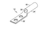
- FIG. 3is a perspective view of one embodiment of the electrical connector shown in FIG. 2 ;
- FIG. 4is a perspective view of the electrical connector shown in FIG. 3 after being subjected to a temperature above a predetermined temperature;
- FIG. 5is a perspective view of an alternate embodiment of the invention which uses a Radio-Frequency Identification (RFID) tag attached to the connector;
- RFIDRadio-Frequency Identification
- FIG. 6is a diagram showing connection of components of the electrical connector shown in FIG. 5 ;
- FIG. 7is a diagram showing use of a system incorporating features of the invention.
- FIG. 8is a diagram showing connection of components of an alternate embodiment of the invention shown in FIG. 6 ;
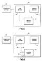
- FIG. 9is a block diagram showing another alternate embodiment of the invention.
- FIG. 10is a block diagram showing another alternate embodiment of the invention.
- FIG. 11is a block diagram showing another alternate embodiment of the invention.
- FIG. 12is a block diagram showing another alternate embodiment of the invention.
- FIG. 13is a block diagram showing another alternate embodiment of the invention.
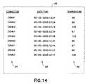
- FIG. 14is a diagram shown a possible display of data on a reader
- FIG. 15is a perspective view of one embodiment of the invention.
- FIG. 16is a perspective view of another embodiment of the invention.
- FIG. 17is a perspective view of a protective cover mounted on the connector shown in FIG. 16 .
- FIG. 1there is shown a block diagram of a connector system 10 having an electrical connector 12 incorporating features of the invention.
- a connector system 10having an electrical connector 12 incorporating features of the invention.
- the inventionwill be described with reference to the exemplary embodiments shown in the drawings, it should be understood that the invention can be embodied in many alternate forms of embodiments. In addition, any suitable size, shape or type of elements or materials could be used.
- the electrical connector 12is adapted to electrically connect a first electrical conductor 14 with a second electrical conductor 16 .
- the electrical connector 12generally comprises a connector section 18 and a connector performance indicating section 20 connected to the connector section.
- the connector section 18comprises a first connection section 22 and a second connection section 24 .
- the connector sectioncould comprise more than two connection sections.
- the connector section 18could comprise any suitable shape.
- the connector section 18could also be comprised of a one-piece member or a multi-piece member(s).
- the first connection section 22is adapted to electrically and mechanically connect to the first conductor 14 .
- the second connection section 24is adapted to electrically and mechanically connect to the second conductor 16 .
- the first connection section 22 and/or the second connection section 24could comprise any suitable type of connection sections including, for example, compression sections, press-fit sections, fastener receiving sections, etc.
- the connector performance indicating section 20is connected to the connector section in any suitable fashion.
- the connector performance indicating section 20could be painted onto the connector section 18 , or attached to the connector section such as by adhesive or epoxy, or retained to the connector section by a fastener, or retained by a deformed portion of the connector section, or received in a slot shaped receiving section of the connector section 18 .
- the connector performance indicating section 20preferably comprises a temperature sensitive chemical indicator or phase change temperature indicator adapted to signal and permanently record a temperature of a portion of the connector section above a predetermined temperature.
- the connector performance indicating section 20could comprise a phase change temperature indicating sticker, label or paint providing the feature of a permanent color change when a specified temperature is exceeded.
- a coatingwhich, by a perceptible change in color indicate that a pre-selected temperature has been reached or exceeded, such as Therm-O-SignalTM sold by Lakfabriek Korthals BV, of Ijmuiden, The Netherlands could be used as the connector performance indicating section 20 .
- the connector performance indicating section 20could be an irreversible temperature label which contains one or more sealed temperature sensitive chemical indicators which sense and record surface temperatures, such as sold by Telatemp Corporation of Fullerton, Calif. In alternate embodiments, any suitable type of temperature sensitive connector performance indicating section could be provided on the electrical connector 12 .
- This inventionprovides a connector design with a direct performance feedback for field application and maintenance.
- the phase change temperature indicating materialcould be directly applied to the electrical connector during manufacture. If the connector exceeds an allowable application temperature during service, the color on the exterior of the connector can change. This can provide direct feedback that a maintenance issue exists.
- the first applicationis for power connectors.
- any power connector exceeding an application temperaturewould have its indicator change color permanently.
- This permanent color changeprovides an advantage versus infra-red thermal imaging devices that only show temperature at a given point in time.
- infra-red thermal imaging deviceif the circuit being measured is not currently under an electrical load the infra-red thermal imaging will not detect a high resistance joint.
- the connector performance indicating section 20will record an excess temperature which can be read at a later time after the excess heat occurs.
- a connectormay not see a fault current for a long period of time.
- the connectorcan experience damage reducing future performance and safety.
- the phase change materialis used with a grounding connector, it will have the ability to show that a fault current was experienced as indicated by color change.
- a field maintenance personcan then have the opportunity to inspect the connector and other surrounding equipment for possible damage and take corrective action.
- the inventioncould be used in applications other than power and ground applications.
- the following illustrationsare offered to show one way the phase change material may be observed on a compression connector. Many variations of connectors and locations for the phase change material can be considered.
- the connector performance indicating section 20is painted onto the connector section 18 as a dot and has a general silver color. In an alternate embodiment, the connector performance indicating section 20 could have any suitable shape and any suitable natural color.
- the first connection section 22comprises a fastener connection section which is adapted to receive fasteners (not shown) to attach the first connection section to the first conductor.
- the second connection section 24comprises a tube shaped section which is adapted to receive an end of the second conductor and be crimped or compressed onto the second conductor.
- the electrical connector 12 of FIG. 3is shown after the connector has been subjected to heat above a predetermined temperature.
- the color of the connector performance indicating section 20has changed from silver to black. This provides a simple and easy to identify indication that the connector 12 has been subjected to a temperature above the predetermined temperature. This can signal or indicate that the connection with the first or second conductors by the electrical connector is having, or has had, a connector performance issue. This provides a performance feedback for the electrical connector and can signal maintenance issues with the electrical connector or the joints with the first or second electrical conductors.
- the color indicating an over-temperature conditioncould be a color other than black. For example, the color could be blue, grey, orange, white, green, etc.
- the connector performance indicating section 20could change to any suitable natural color or signaling pattern or indicium. In one type of embodiment, the paint starts as red, and changes to black at about 65° C.
- the inventioncould be combined with thermal shielding of the temperature sensitive indicator material.
- the thermal shieldingcould shield the temperature sensitive indicator material from sources of heat that are not generated by a corresponding electrical connector.
- the electrical connectorcould be located close to a heat source, such as a furnace or burner.
- the heating of one connectorcould cause the external temperature sensitive indicator material on the other connector to turn color.
- One possible shieldingis a transparent UV or heat resistant coating over the exterior surface of the temperature sensitive indicator material.
- the temperature sensitive indicator materialcould be insulated on the external side, but not the side adjacent to the connector itself. A cowl or hood could serve the same purpose.
- the inventioncould also be used by mixing a temperature sensitive indicator material, or even a non-temperature sensitive indicator material which is merely colored, with a melt material that melts at a predetermined temperature.
- the melt materialsuch as paraffin or solder or plastic, could be positioned inside of an electrical connector. If the conductive portion of the connector reaches the melting point of the melt material, the material could melt and pour out of a hole in the electrical connector or coating of the electrical connector. If provided as a paint, the paint could make the material visible for inspection purposes.
- the temperature sensitive indicator material or colored markercould be encapsulated by the melt material, which could subsequently rupture upon excessive heat above a predetermined temperature, or could be mixed with the melt material, etc.
- the inventioncan provide a compressible electrical connector that carries a performance indicator.
- a compressible electrical connectoris different from circuit breakers and fuses.
- the compressible connectorsare stamped with various numbers and symbols.
- the indicia stamped on the connectorscan smear or distort after the crimp is made. Therefore, was not obvious not include a performance indicator on a compressible connector because it did not make sense, prior to the invention, to add a component (and cost) that one skilled in the art would have known would be mangled during the crimping process.
- it has been discovered that enough of the performance indicatorcan remain on the connector after the crimping operation to provide a visual indication.
- the connector member having the indicatorcould be an electrical contact terminal which is part of an electronic device, or located on a housing of an electrical connector.
- the outer surface of the connectorcan define a dimple or recessed area that can receive the performance indicator. This can help with any surface wiping problems. Applying paint to the conductor receiving sides of a compressible connector might not be commercially viable, because the insulation of the mating wires could obscure the sides of the connector from view. This could defeat the purpose of the visual indicator. However, in some embodiments, placement of the material on the mating sides of the connector could be used.
- a heat indication sticker that is attached to the connector before or after the crimpcould also be used. These types of stickers are already commercially available. Temperature indicating paint could also be applied to the connector before or after crimping. Other optional features include a UV protective layer over the paint/sticker and/or a colored material that changes phase when exposed to heat. For example, solid to liquid, and if it cools down again, the shape of the re-solidified material would be different. Multiple indicators can also be used on a single connector. For example, each could be activated by a particular temperature range, e.g. 60-65 C, 65-70 C, etc.
- an electrical connector 30comprising a connector section 32 and a connector performance indicating section 34 .
- the connector performance indicating section 34comprises a Radio-Frequency Identification (RFID) tag 36 attached to the connector section 32 .
- the connector section 32generally comprises a first connection section 38 and a second connection section 40 . In alternate embodiments, more than two connection sections could be provided.
- the connector sectionis preferably made of electrically conductive material, or at least has an electrically conductive path between the two connection section 38 , 40 .
- the connection sections 38 , 40are tube shaped sections adapted to be crimped onto separate electrical conductors. Thus, the connector section can electrically and mechanically connect the separate electrical conductors to each other. In alternate embodiments, any suitable size and shaped connection sections could be provided.
- the RFID tag 36generally comprises an RFID chip 42 and an antenna 44 .
- the RFID chip 42comprises a transceiver which is adapted to send a signal to the antenna based upon receipt of an appropriate incoming radio frequency signal by the antenna.
- the incoming radio frequency signalpowers the RFID tag.
- the signal adapted to be sent to the antenna by the RFID chipcomprises a fixed identifier code or other fixed code stored in the RFID chip.
- a RFID tagcould be positioned on the connector in such a way that the antenna 44 and chip 42 are not destroyed by crimping of the connection sections 38 , 40 onto their respective conductors.
- the RFID tagcan function as part of the performance indicating section attached to the crimpable connector 30 . Similar to the paint/sticker embodiments described above, the RFID tag could be used to signal occurrence of a temperature of a portion of the connector section above a predetermined temperature (an over-temperature occurrence) and/or transmit heat readings via the RFID tag.
- the connector performance indicating section 34comprises a sensing device 46 .
- the sensing device 46could be any suitable type of sensing device, such as a temperature sensor, a pressure sensor, a strain sensor, a humidity sensor, etc.
- the sensing deviceis a thermocouple adapted to sense temperature of a portion of the connector section 32 .
- any suitable temperature sensorcould be provided.
- the thermocouple 46provides part of an electrical circuit between the RFID chip 42 and the antenna section 44 .
- the thermocouple 46is normally closed in an ON state to allow transmission of signals between the chip section 42 and the antenna section 44 .
- thermocouple 46if the thermocouple 46 is subjected to a temperature above a predetermined temperature, the thermocouple can open to create an OFF state. This would break the circuit path between the chip section 42 and the antenna section 44 thereby inactivating the RFID tag. This inactivation by the thermocouple is preferably permanent. However, in an alternate embodiment it could be temporary, such as by repair, replacement or resetting of the thermocouple.
- the systemcomprises a reader 52 .
- the reader 52is an RFID reader which is adapted to output a first radio frequency signal 54 which is sent by wireless transmission over the air in the direction towards the connectors 30 .
- the first signal 54can be received by the antenna sections 44 and sent to the chip sections 42 .
- the chip sections 42then respond by sending a second signal, with each of their respectively different codes, back to the antenna sections 44 for transmission as second radio frequency signals 56 ′, 56 ′′, 56 ′′′ back to the reader 52 .
- the readercan read and perhaps record the second radio frequency signals.
- the thermocouple 46 of the connector Awould open to form an OFF state. Therefore, signal 56 ′ would not be received by the reader 52 and the user would know that there was a potential problem with connector A.
- non-receipt of the signal 56 ′could be used to signal occurrence of a temperature at the connector 30 above a predetermined temperature; the temperature required to open the thermocouple 46 of the connector A.
- the usercould review the connector A and determine if it should be repaired or replaced.
- a passive temperature sensing RFID tagcan be provided as part of an electrical connector, such as attached as an adhesive tag for example.
- a readercan be taken by a user (or activated if mounted in a stationary location or on a vehicle, and request sensed data (such as temperature for example) and perhaps form a log.
- the datacan be used to alert a condition of a probably damaged connector, or indicate that a connector is near a condition where it should be service or replaced.
- the inventioncan utilized the electrically conductive portion of the connector to enhance the RF signal by forming the antenna, part of the antenna, or a second antenna.
- the inventioncan utilize a conductor/connector network as the antenna.
- the inventioncan utilize a passive tag to record and communicate connector(s) condition(s) such as temperature for example.
- the chip section 42is directly coupled to the antenna section 46
- the sensing device 46is coupled to the chip section 42 as an input on line 58 , or as part of a circuit with lines 58 and 60 , or as part of a circuit to ground 62 with lines 58 and 64 .
- the sensing deviceis a thermocouple which, similar to the embodiment described above, is adapted to be open or closed based upon sensed temperature of the connection section 32 . If the temperature of a portion of the connection section 32 exceeds a predetermined temperature (e.g., the temperature needed to open the thermocouple the chip section 42 can be prevented from sending the second radio frequency signal 56 to the reader.
- the circuitcould be adapted to turn the RFID feature ON when an over-temperature condition occurs (or other predetermined sensed condition occurs).
- a single connector 66could comprise multiple RFID tags 36 , 36 ′, 36 ′′, etc.
- Each tagcould be connected to a different sensing device 46 , 46 ′, 46 ′′, etc.
- Each tagpreferably has a different RFID code and each sensing device has a different set point for ON/OFF, such as three thermocouples having three different open/closed temperature set points for example.
- the tagscan each have their own antenna sections, or can share a common antenna as shown in FIGS. 10 and 11 .
- the sensing device(s)could be provided on or in the chip.
- the antenna section(s)could be provided integrally with the chips.
- the connector section 32 of the connectoror another electrically conductive portion of the connector) could provide the function of the antenna section. Thus, a separate member for the antenna section is not required.
- a single RFID chip 68is provided.
- the chipis coupled to the sensing device 46 and antenna 44 such as described with reference to FIGS. 6 and 8 for example.
- the chip 68has multiple RFID chip sections 70 , 72 , 74 . Each chip section has its own RFID code and may be separately coupled to different outputs or inputs of the sensing device 46 .
- the sensing device 46could be adapted to output different signals, or provide different circuit paths, to the chip 68 based upon different sensed conditions of the connector.
- the sensing devicecould be adapted to sense three pre-set different temperatures and allow use or non-use of the respective chip sections 70 - 74 based upon those temperatures.
- the chip 68could output three RFID codes, two RFID codes, one RFID code or no RFID codes based upon the maximum temperature which the sensing device has been exposed to.
- the sensing deviceis a non-permanent type of sensing device, the chip 68 could output three RFID codes, two RFID codes, one RFID code or no RFID codes based upon the actual temperature of the connector during reading with the reader 52 .
- a RFID chip 76is provided which is coupled to an antenna section 44 and a sensing device 46 , such as described with reference to FIGS. 6 and 8 for example.
- the chip 76comprises a transceiver section 78 and a code selector section 80 .
- the sensing deviceis adapted to provide a sensed condition status (such as temperature, pressure, strain, etc.) (either maximum or current state for example) of the connector to the chip 76 .
- the code selector section 80is adapted to select a code to be transmitted by the antenna to the reader based upon the sensed condition status. For example, the code could represent the actual temperature of the connector or the maximum temperature reached by the connector.
- the code selector sectioncould be adapted to send the RFID code with a base code section and an attached sensed condition code section as a combined hybrid RFID signal.
- the reader 52 shown in FIG. 7could have a display 82 which is adapted to display an identification 84 of connectors, a temperature 86 (or maximum reached temperature) of the connector, and a date/time 88 the reading was taken.
- FIG. 15shows one embodiment of the invention wherein the RFID tag 36 is part of an electrical connector 90 having a connector section 92 .
- the connector section 92comprises a first connection section 94 , a second connection section 96 , and a transition section 98 between the two connection sections 94 , 96 .
- the first connection section 94comprises a fastener connection section which is adapted to receive fasteners (not shown) to attach the first connection section to the first conductor.
- the second connection section 96comprises a tube shaped section which is adapted to receive an end of the second conductor and be crimped or compressed onto the second conductor.
- the RFID tagis connected to the transition section 98 ; perhaps with a sensing device between the RFID tag and the transition section.
- the sensing devicecould comprise electrically conductive paint of a label which is adapted to provide an electrical path between the chip and the antenna of the tag, but not provide the path when heated above a predetermined temperature (such as a permanent break in the circuit path).
- part of the electrical circuit between the RFID chip and the antennacould be comprises of an electrically conductive material which is adapted to melt at a predetermined temperature and flow way from the circuit path, thereby causing a break in the circuit path when an over-temperature condition occurs.
- the tagcould also be connected to the connector section by one or more intermediate members.
- FIG. 16shows another embodiment of the invention wherein the RFID tag 36 is part of an electrical connector 100 having a connector section 102 .
- the connector section 102comprises a first connection section 104 , a second connection section 106 , and a middle section 108 between the two connection sections 104 , 106 .
- the first connection section 104comprises a tube shaped section which is adapted to receive an end of the first conductor and be crimped or compressed onto the first conductor.
- the second connection section 106comprises a tube shaped section which is adapted to receive an end of the second conductor and be crimped or compressed onto the second conductor.
- the RFID tagis connected to the middle section 108 ; perhaps with a sensing device between the RFID tag and the transition section.
- the tag 36is located at an area space from the crimp zones of the sections 104 , 106 .
- the connector 100is shown connected to two conductors 110 , 112 .
- a protective cover 114can be mounted over the connector 100 to protect the RFID tag 36 .
- thermocouple and wire combinationexamples include use of a thermocouple and wire combination. Other temperature sensing devices could be used.
- the inventioncan utilize the features of transmitting signals through radio frequency coupled with sensing parameters such as temperature, pressure, stain, and humidity for example.
- the inventioncan be used with compression or mechanical connectors, for example, and/or with providing protecting covers to transition surfaces or non-deformed surfaces.
- the inventioncan be used to achieve performance (real time or potentially data logged) measures on an electrical connector or device of apparatus having an electrical connector.
Landscapes
- Engineering & Computer Science (AREA)
- Physics & Mathematics (AREA)
- General Physics & Mathematics (AREA)
- Computer Hardware Design (AREA)
- Microelectronics & Electronic Packaging (AREA)
- Theoretical Computer Science (AREA)
- Arrangements For Transmission Of Measured Signals (AREA)
Abstract
Description
Claims (17)
Priority Applications (5)
| Application Number | Priority Date | Filing Date | Title |
|---|---|---|---|
| US11/172,223US7306489B2 (en) | 2004-07-26 | 2005-06-29 | Performance indicating electrical connector |
| CA002573195ACA2573195A1 (en) | 2004-07-26 | 2005-07-20 | Performance indicating electrical connector |
| PCT/US2005/025590WO2006020293A1 (en) | 2004-07-26 | 2005-07-20 | Performance indicating electrical connector |
| EP05774836AEP1779477A4 (en) | 2004-07-26 | 2005-07-20 | Performance indicating electrical connector |
| CN2005800251085ACN1989662B (en) | 2004-07-26 | 2005-07-20 | Electric connector and assembling and checking method thereof |
Applications Claiming Priority (2)
| Application Number | Priority Date | Filing Date | Title |
|---|---|---|---|
| US59130704P | 2004-07-26 | 2004-07-26 | |
| US11/172,223US7306489B2 (en) | 2004-07-26 | 2005-06-29 | Performance indicating electrical connector |
Publications (2)
| Publication Number | Publication Date |
|---|---|
| US20060019540A1 US20060019540A1 (en) | 2006-01-26 |
| US7306489B2true US7306489B2 (en) | 2007-12-11 |
Family
ID=35657833
Family Applications (1)
| Application Number | Title | Priority Date | Filing Date |
|---|---|---|---|
| US11/172,223Active2026-10-17US7306489B2 (en) | 2004-07-26 | 2005-06-29 | Performance indicating electrical connector |
Country Status (5)
| Country | Link |
|---|---|
| US (1) | US7306489B2 (en) |
| EP (1) | EP1779477A4 (en) |
| CN (1) | CN1989662B (en) |
| CA (1) | CA2573195A1 (en) |
| WO (1) | WO2006020293A1 (en) |
Cited By (36)
| Publication number | Priority date | Publication date | Assignee | Title |
|---|---|---|---|---|
| US20060166546A1 (en)* | 2005-01-26 | 2006-07-27 | Minoru Ashizawa | Connector device, apparatus and method for acquiring data of electrical device using the connector device, and control system for electrical device |
| US20070197086A1 (en)* | 2004-10-28 | 2007-08-23 | Thomas Horn | Arrangement for monitoring patch fields at distribution points in data networks |
| US20080100456A1 (en)* | 2006-10-31 | 2008-05-01 | Downie John D | System for mapping connections using RFID function |
| WO2008054730A3 (en)* | 2006-10-31 | 2008-08-14 | Corning Cable Sys Llc | Radio frequency identification transponder for communicating condition of a component |
| US7547150B2 (en) | 2007-03-09 | 2009-06-16 | Corning Cable Systems, Llc | Optically addressed RFID elements |
| WO2009096814A3 (en)* | 2008-01-31 | 2009-09-24 | Khozyainov Boris Alekseevich | System for monitoring plug connections using radio-frequency labels |
| US20090258548A1 (en)* | 2008-04-09 | 2009-10-15 | Panduit Corp. | Beam clamp |
| US7667574B2 (en) | 2006-12-14 | 2010-02-23 | Corning Cable Systems, Llc | Signal-processing systems and methods for RFID-tag signals |
| US7760094B1 (en) | 2006-12-14 | 2010-07-20 | Corning Cable Systems Llc | RFID systems and methods for optical fiber network deployment and maintenance |
| US7782202B2 (en) | 2006-10-31 | 2010-08-24 | Corning Cable Systems, Llc | Radio frequency identification of component connections |
| US20100295691A1 (en)* | 2009-05-22 | 2010-11-25 | King Jr Lloyd Herbert | Intelligent wire connectors |
| US7855697B2 (en) | 2007-08-13 | 2010-12-21 | Corning Cable Systems, Llc | Antenna systems for passive RFID tags |
| US20110080057A1 (en)* | 2008-11-17 | 2011-04-07 | Rochester Institute Of Technology | Power harvesting device and method of use thereof |
| US7965186B2 (en) | 2007-03-09 | 2011-06-21 | Corning Cable Systems, Llc | Passive RFID elements having visual indicators |
| CN102346865A (en)* | 2010-07-30 | 2012-02-08 | 中国科学院微电子研究所 | Temperature sensing radio frequency tag and circuit and method for sensing temperature change by using same |
| US8172468B2 (en) | 2010-05-06 | 2012-05-08 | Corning Incorporated | Radio frequency identification (RFID) in communication connections, including fiber optic components |
| US8248208B2 (en) | 2008-07-15 | 2012-08-21 | Corning Cable Systems, Llc. | RFID-based active labeling system for telecommunication systems |
| US8264366B2 (en) | 2009-03-31 | 2012-09-11 | Corning Incorporated | Components, systems, and methods for associating sensor data with component location |
| US8264355B2 (en) | 2006-12-14 | 2012-09-11 | Corning Cable Systems Llc | RFID systems and methods for optical fiber network deployment and maintenance |
| US8731405B2 (en) | 2008-08-28 | 2014-05-20 | Corning Cable Systems Llc | RFID-based systems and methods for collecting telecommunications network information |
| US9159012B2 (en) | 2009-11-30 | 2015-10-13 | Corning Incorporated | RFID condition latching |
| US9165232B2 (en) | 2012-05-14 | 2015-10-20 | Corning Incorporated | Radio-frequency identification (RFID) tag-to-tag autoconnect discovery, and related methods, circuits, and systems |
| US9563832B2 (en) | 2012-10-08 | 2017-02-07 | Corning Incorporated | Excess radio-frequency (RF) power storage and power sharing RF identification (RFID) tags, and related connection systems and methods |
| US20170122813A1 (en)* | 2015-11-02 | 2017-05-04 | Tyco Electronics Corporation | Temperature monitoring systems and methods for electrical power distribution systems |
| US9652709B2 (en) | 2006-10-31 | 2017-05-16 | Fiber Mountain, Inc. | Communications between multiple radio frequency identification (RFID) connected tags and one or more devices, and related systems and methods |
| US9652707B2 (en) | 2006-10-31 | 2017-05-16 | Fiber Mountain, Inc. | Radio frequency identification (RFID) connected tag communications protocol and related systems and methods |
| US9652708B2 (en) | 2006-10-31 | 2017-05-16 | Fiber Mountain, Inc. | Protocol for communications between a radio frequency identification (RFID) tag and a connected device, and related systems and methods |
| US9704373B2 (en) | 2014-05-29 | 2017-07-11 | Thomas & Betts International Llc | Smart lug system |
| US10032102B2 (en) | 2006-10-31 | 2018-07-24 | Fiber Mountain, Inc. | Excess radio-frequency (RF) power storage in RF identification (RFID) tags, and related systems and methods |
| US10285301B1 (en) | 2018-04-23 | 2019-05-07 | Dell Products, L.P. | Multi-axis alignment enclosure system for wall-mounted power delivery system |
| US10345159B1 (en) | 2018-03-20 | 2019-07-09 | Klt Technology, Inc. | Visual and electronically readable temperature indicator |
| EP3372972A4 (en)* | 2016-12-30 | 2019-08-21 | Beijing Goldwind Science & Creation Windpower Equipment Co., Ltd. | ELECTRICAL CONNECTOR, FLUID STATE TESTING DEVICE, AND FLUID HEAT EXCHANGE SYSTEM |
| US10401232B2 (en) | 2016-01-25 | 2019-09-03 | Klt Technology, Inc. | Visual and electronically readable temperature indicator |
| US10784641B2 (en) | 2018-01-31 | 2020-09-22 | Abb Schweiz Ag | Crimping tool with wireless communication system |
| US20240039218A1 (en)* | 2022-07-29 | 2024-02-01 | Te Connectivity Solutions Gmbh | Apparatus and methods for monitoring the temperature of high voltage electrical cable connectors |
| DE102022133580A1 (en) | 2022-12-16 | 2024-06-27 | Bayerische Motoren Werke Aktiengesellschaft | Vehicle with on-board energy system and method for operating the vehicle |
Families Citing this family (32)
| Publication number | Priority date | Publication date | Assignee | Title |
|---|---|---|---|---|
| FI119405B (en)* | 2006-02-21 | 2008-10-31 | Abb Oy | Device for conditioning control of electrical connections |
| GB0624201D0 (en)* | 2006-12-04 | 2007-01-10 | Pilkington Automotive D Gmbh | Connector |
| US7604399B2 (en)* | 2007-05-31 | 2009-10-20 | Siemens Energy, Inc. | Temperature monitor for bus structure flex connector |
| US8149127B2 (en)* | 2007-09-24 | 2012-04-03 | John Mezzalingua Associates, Inc. | Coaxial cable connector with an internal coupler and method of use thereof |
| US8400319B2 (en)* | 2007-09-24 | 2013-03-19 | John Mezzalingua Associates, Inc. | Coaxial cable connector with an external sensor and method of use thereof |
| US8400318B2 (en)* | 2007-09-24 | 2013-03-19 | John Mezzalingua Associates, Inc. | Method for determining electrical power signal levels in a transmission system |
| US8773255B2 (en)* | 2007-09-24 | 2014-07-08 | Ppc Broadband, Inc. | Status sensing and reporting interface |
| US7733236B2 (en)* | 2007-09-24 | 2010-06-08 | John Mezzalingua Associates, Inc. | Coaxial cable connector and method of use thereof |
| US8570178B2 (en)* | 2007-09-24 | 2013-10-29 | Ppc Broadband, Inc. | Coaxial cable connector with internal floating ground circuitry and method of use thereof |
| US8419464B2 (en)* | 2008-11-17 | 2013-04-16 | Ppc Broadband, Inc. | Coaxial connector with integrated molded substrate and method of use thereof |
| US8414326B2 (en)* | 2008-11-17 | 2013-04-09 | Rochester Institute Of Technology | Internal coaxial cable connector integrated circuit and method of use thereof |
| US8303334B2 (en)* | 2008-11-17 | 2012-11-06 | John Mezzalingua Associates, Inc. | Embedded coupler device and method of use thereof |
| US8618944B2 (en)* | 2009-12-03 | 2013-12-31 | Ppc Broadband, Inc. | Coaxial cable connector parameter monitoring system |
| NO332029B1 (en) | 2010-09-30 | 2012-05-29 | Gantel Properties Ltd | Fire prevention system and method in electrical systems |
| US8604936B2 (en) | 2010-12-13 | 2013-12-10 | Ppc Broadband, Inc. | Coaxial cable connector, system and method of use thereof |
| EP2528012A1 (en)* | 2011-05-27 | 2012-11-28 | Data-Complex GmbH | Device, system and method for monitoring a number of holder devices |
| DE102011079407A1 (en)* | 2011-07-19 | 2013-01-24 | Siemens Aktiengesellschaft | Carrier with a liquid solder wettable test surface and method for its use |
| US20140015644A1 (en)* | 2011-12-27 | 2014-01-16 | The Gillette Company | Apparatus and Method for Providing Product Information |
| IN2014DN06566A (en)* | 2012-02-01 | 2015-05-22 | Corning Inc | |
| US9317726B2 (en)* | 2012-04-23 | 2016-04-19 | Avery Dennison Corporation | Radio frequency identification sensor assembly |
| NO20140862A1 (en)* | 2014-07-07 | 2015-09-14 | El Watch As | Damage prevention marking system for conductors and connection points in electrical systems with data capture |
| SE540543C2 (en)* | 2015-03-03 | 2018-09-25 | Roxtec Ab | An inspection system for cable, pipe or wire transits |
| JP6563272B2 (en)* | 2015-08-04 | 2019-08-21 | タイコエレクトロニクスジャパン合同会社 | Electrical terminal |
| US11877087B2 (en)* | 2015-08-19 | 2024-01-16 | NeoGenesys, Inc. | Methods and systems for remote monitoring of electrical equipment |
| FR3047591A1 (en)* | 2016-02-10 | 2017-08-11 | Jinnov'or | A TRACEABILITY SYSTEM FOR A GOODS COMPRISING A LABEL FOR INDICATING THAT AT LEAST ONE TEMPERATURE THRESHOLD HAS BEEN REACHED AND / OR EXCEEDED BY MEANS OF RADIO-IDENTIFICATION |
| EP3752806A4 (en)* | 2018-02-13 | 2021-09-29 | ABB Schweiz AG | BUSBAR CONNECTION, SYSTEM FOR MEASURING THE TEMPERATURE OF BUSBAR CONNECTIONS AND INTERNET OF THINGS SYSTEM |
| DE102018211698A1 (en)* | 2018-07-13 | 2020-01-16 | Volkswagen Aktiengesellschaft | Connectors |
| CN109599289A (en)* | 2018-11-20 | 2019-04-09 | 国网天津市电力公司 | 10kV disconnecting link overheat instruction detection method |
| CN109616361A (en)* | 2018-11-20 | 2019-04-12 | 国网天津市电力公司 | 10kV Knife Switch Overheating Indicator |
| US11781916B2 (en)* | 2020-01-17 | 2023-10-10 | Shenzhen Hypersynes Co., Ltd. | Tag antenna and passive temperature detection apparatus |
| CN114018420A (en)* | 2020-07-16 | 2022-02-08 | 浙江悦和科技有限公司 | Temperature measuring device for cable connector |
| US11699885B1 (en)* | 2022-11-10 | 2023-07-11 | Global Inventive Consulting, Inc. | RFID-enabled electrical connector |
Citations (23)
| Publication number | Priority date | Publication date | Assignee | Title |
|---|---|---|---|---|
| US4170190A (en) | 1978-04-04 | 1979-10-09 | Warner John H | Method for detecting and a detector for indicating excessive temperature at electrical wiring devices |
| US4470711A (en)* | 1983-03-30 | 1984-09-11 | General Electric Company | Electrical device termination high temperature indicator |
| US4891250A (en) | 1988-02-17 | 1990-01-02 | Weibe Edward W | Electronic component operating temperature indicator |
| US5036164A (en) | 1990-07-25 | 1991-07-30 | Burndy Corporation | Multiple tap ground connector |
| US5103068A (en) | 1991-02-15 | 1992-04-07 | Burndy Corporation | Connector twist tie |
| US5162615A (en) | 1991-02-15 | 1992-11-10 | Burndy Corporation | Full closure H-shaped connector |
| US5188542A (en)* | 1991-12-05 | 1993-02-23 | Gray Ballman | Electrical connector with integral strain relief and mount, and overtemperature indicator |
| US5200576A (en) | 1991-02-15 | 1993-04-06 | Burndy Corporation | Multi-point contact compression connector |
| US5552564A (en) | 1994-11-23 | 1996-09-03 | Burndy Corporation | Range enhancement for H-shaped compression connector |
| US5567175A (en)* | 1995-05-01 | 1996-10-22 | Woods Industries, Inc. | Premold insert for a transparent plug |
| US5786626A (en)* | 1996-03-25 | 1998-07-28 | Ibm Corporation | Thin radio frequency transponder with leadframe antenna structure |
| US6114941A (en) | 1997-12-08 | 2000-09-05 | Alliedsignal Inc. | Thermal switch with activation indicator |
| US6412977B1 (en)* | 1998-04-14 | 2002-07-02 | The Goodyear Tire & Rubber Company | Method for measuring temperature with an integrated circuit device |
| US6525270B1 (en) | 2000-10-13 | 2003-02-25 | Fci Usa, Inc. | Compression connector |
| US6538204B2 (en) | 2001-07-10 | 2003-03-25 | Fci Usa, Inc. | Electrical compression connector |
| US6552271B2 (en) | 2001-07-10 | 2003-04-22 | Fci Usa, Inc. | Electrical compression connector |
| DE10244304B3 (en) | 2002-09-23 | 2004-03-18 | Data-Complex E.K. | Arrangement for monitoring patch panels at distributor points in data networks has patch cables that can be plugged into connections in patch fields with plugs, each fitted with a transponder |
| US6784802B1 (en)* | 1999-11-04 | 2004-08-31 | Nordx/Cdt, Inc. | Real time monitoring of cable patch panel |
| US6818830B2 (en) | 2002-09-26 | 2004-11-16 | Panduit Corp. | H-tap compression connector |
| US6846989B2 (en) | 2002-09-26 | 2005-01-25 | Panduit Corp. | Multi-tap compression connector |
| US20050242086A1 (en) | 2004-04-28 | 2005-11-03 | Mamoru Imura | Radio frequency identification controlled heatable objects |
| US20050285735A1 (en) | 2004-04-28 | 2005-12-29 | Mamoru Imura | Tag assembly for radio frequency identification controlled heatable objects |
| US20060006987A1 (en) | 2004-07-07 | 2006-01-12 | Fujitsu Limited | Radio IC tag reader writer, radio IC tag system, and radio IC tag data writing method |
- 2005
- 2005-06-29USUS11/172,223patent/US7306489B2/enactiveActive
- 2005-07-20CNCN2005800251085Apatent/CN1989662B/ennot_activeExpired - Fee Related
- 2005-07-20CACA002573195Apatent/CA2573195A1/ennot_activeAbandoned
- 2005-07-20EPEP05774836Apatent/EP1779477A4/ennot_activeWithdrawn
- 2005-07-20WOPCT/US2005/025590patent/WO2006020293A1/enactiveApplication Filing
Patent Citations (24)
| Publication number | Priority date | Publication date | Assignee | Title |
|---|---|---|---|---|
| US4170190A (en) | 1978-04-04 | 1979-10-09 | Warner John H | Method for detecting and a detector for indicating excessive temperature at electrical wiring devices |
| US4470711A (en)* | 1983-03-30 | 1984-09-11 | General Electric Company | Electrical device termination high temperature indicator |
| US4891250A (en) | 1988-02-17 | 1990-01-02 | Weibe Edward W | Electronic component operating temperature indicator |
| US5036164A (en) | 1990-07-25 | 1991-07-30 | Burndy Corporation | Multiple tap ground connector |
| US5103068A (en) | 1991-02-15 | 1992-04-07 | Burndy Corporation | Connector twist tie |
| US5162615A (en) | 1991-02-15 | 1992-11-10 | Burndy Corporation | Full closure H-shaped connector |
| US5200576A (en) | 1991-02-15 | 1993-04-06 | Burndy Corporation | Multi-point contact compression connector |
| US5162615B1 (en) | 1991-02-15 | 1994-07-26 | Burndy Corp | Full closure h-shaped connector |
| US5188542A (en)* | 1991-12-05 | 1993-02-23 | Gray Ballman | Electrical connector with integral strain relief and mount, and overtemperature indicator |
| US5552564A (en) | 1994-11-23 | 1996-09-03 | Burndy Corporation | Range enhancement for H-shaped compression connector |
| US5567175A (en)* | 1995-05-01 | 1996-10-22 | Woods Industries, Inc. | Premold insert for a transparent plug |
| US5786626A (en)* | 1996-03-25 | 1998-07-28 | Ibm Corporation | Thin radio frequency transponder with leadframe antenna structure |
| US6114941A (en) | 1997-12-08 | 2000-09-05 | Alliedsignal Inc. | Thermal switch with activation indicator |
| US6412977B1 (en)* | 1998-04-14 | 2002-07-02 | The Goodyear Tire & Rubber Company | Method for measuring temperature with an integrated circuit device |
| US6784802B1 (en)* | 1999-11-04 | 2004-08-31 | Nordx/Cdt, Inc. | Real time monitoring of cable patch panel |
| US6525270B1 (en) | 2000-10-13 | 2003-02-25 | Fci Usa, Inc. | Compression connector |
| US6538204B2 (en) | 2001-07-10 | 2003-03-25 | Fci Usa, Inc. | Electrical compression connector |
| US6552271B2 (en) | 2001-07-10 | 2003-04-22 | Fci Usa, Inc. | Electrical compression connector |
| DE10244304B3 (en) | 2002-09-23 | 2004-03-18 | Data-Complex E.K. | Arrangement for monitoring patch panels at distributor points in data networks has patch cables that can be plugged into connections in patch fields with plugs, each fitted with a transponder |
| US6818830B2 (en) | 2002-09-26 | 2004-11-16 | Panduit Corp. | H-tap compression connector |
| US6846989B2 (en) | 2002-09-26 | 2005-01-25 | Panduit Corp. | Multi-tap compression connector |
| US20050242086A1 (en) | 2004-04-28 | 2005-11-03 | Mamoru Imura | Radio frequency identification controlled heatable objects |
| US20050285735A1 (en) | 2004-04-28 | 2005-12-29 | Mamoru Imura | Tag assembly for radio frequency identification controlled heatable objects |
| US20060006987A1 (en) | 2004-07-07 | 2006-01-12 | Fujitsu Limited | Radio IC tag reader writer, radio IC tag system, and radio IC tag data writing method |
Cited By (54)
| Publication number | Priority date | Publication date | Assignee | Title |
|---|---|---|---|---|
| US20070197086A1 (en)* | 2004-10-28 | 2007-08-23 | Thomas Horn | Arrangement for monitoring patch fields at distribution points in data networks |
| US7629893B2 (en)* | 2004-10-28 | 2009-12-08 | Data-Complex Gmbh | Arrangement for monitoring patch fields at distribution points in data networks using reader coils to detect and communicate with transponders |
| US7602289B2 (en)* | 2005-01-26 | 2009-10-13 | Hitachi, Ltd. | Connector device, apparatus and method for acquiring data of electrical device using the connector device, and control system for electrical device |
| US20060166546A1 (en)* | 2005-01-26 | 2006-07-27 | Minoru Ashizawa | Connector device, apparatus and method for acquiring data of electrical device using the connector device, and control system for electrical device |
| US7782202B2 (en) | 2006-10-31 | 2010-08-24 | Corning Cable Systems, Llc | Radio frequency identification of component connections |
| US7772975B2 (en) | 2006-10-31 | 2010-08-10 | Corning Cable Systems, Llc | System for mapping connections using RFID function |
| US8421626B2 (en) | 2006-10-31 | 2013-04-16 | Corning Cable Systems, Llc | Radio frequency identification transponder for communicating condition of a component |
| US9652708B2 (en) | 2006-10-31 | 2017-05-16 | Fiber Mountain, Inc. | Protocol for communications between a radio frequency identification (RFID) tag and a connected device, and related systems and methods |
| WO2008054730A3 (en)* | 2006-10-31 | 2008-08-14 | Corning Cable Sys Llc | Radio frequency identification transponder for communicating condition of a component |
| US9652709B2 (en) | 2006-10-31 | 2017-05-16 | Fiber Mountain, Inc. | Communications between multiple radio frequency identification (RFID) connected tags and one or more devices, and related systems and methods |
| US20080100456A1 (en)* | 2006-10-31 | 2008-05-01 | Downie John D | System for mapping connections using RFID function |
| US10032102B2 (en) | 2006-10-31 | 2018-07-24 | Fiber Mountain, Inc. | Excess radio-frequency (RF) power storage in RF identification (RFID) tags, and related systems and methods |
| US9652707B2 (en) | 2006-10-31 | 2017-05-16 | Fiber Mountain, Inc. | Radio frequency identification (RFID) connected tag communications protocol and related systems and methods |
| US8264355B2 (en) | 2006-12-14 | 2012-09-11 | Corning Cable Systems Llc | RFID systems and methods for optical fiber network deployment and maintenance |
| US7760094B1 (en) | 2006-12-14 | 2010-07-20 | Corning Cable Systems Llc | RFID systems and methods for optical fiber network deployment and maintenance |
| US7667574B2 (en) | 2006-12-14 | 2010-02-23 | Corning Cable Systems, Llc | Signal-processing systems and methods for RFID-tag signals |
| US7547150B2 (en) | 2007-03-09 | 2009-06-16 | Corning Cable Systems, Llc | Optically addressed RFID elements |
| US7965186B2 (en) | 2007-03-09 | 2011-06-21 | Corning Cable Systems, Llc | Passive RFID elements having visual indicators |
| US7855697B2 (en) | 2007-08-13 | 2010-12-21 | Corning Cable Systems, Llc | Antenna systems for passive RFID tags |
| US8618912B2 (en)* | 2008-01-31 | 2013-12-31 | Boris A. Khozyainov | System for monitoring detachable connections using RFID tags |
| WO2009096814A3 (en)* | 2008-01-31 | 2009-09-24 | Khozyainov Boris Alekseevich | System for monitoring plug connections using radio-frequency labels |
| US20110012712A1 (en)* | 2008-01-31 | 2011-01-20 | Boris Alekseevich Khozyainov | System for monitoring detachable connections using rfid tags |
| US8096816B2 (en) | 2008-04-09 | 2012-01-17 | Panduit Corp. | Beam clamp |
| US20090258548A1 (en)* | 2008-04-09 | 2009-10-15 | Panduit Corp. | Beam clamp |
| US20110223814A1 (en)* | 2008-04-09 | 2011-09-15 | Panduit Corp. | Beam clamp |
| US7988464B2 (en) | 2008-04-09 | 2011-08-02 | Panduit Corp. | Beam clamp |
| US8248208B2 (en) | 2008-07-15 | 2012-08-21 | Corning Cable Systems, Llc. | RFID-based active labeling system for telecommunication systems |
| US8731405B2 (en) | 2008-08-28 | 2014-05-20 | Corning Cable Systems Llc | RFID-based systems and methods for collecting telecommunications network information |
| US9058529B2 (en) | 2008-08-28 | 2015-06-16 | Corning Optical Communications LLC | RFID-based systems and methods for collecting telecommunications network information |
| US8376774B2 (en)* | 2008-11-17 | 2013-02-19 | Rochester Institute Of Technology | Power extracting device and method of use thereof |
| US20110080057A1 (en)* | 2008-11-17 | 2011-04-07 | Rochester Institute Of Technology | Power harvesting device and method of use thereof |
| US8264366B2 (en) | 2009-03-31 | 2012-09-11 | Corning Incorporated | Components, systems, and methods for associating sensor data with component location |
| US8552876B2 (en)* | 2009-05-22 | 2013-10-08 | The Patent Store Llc | Intelligent wire connectors |
| US20130307528A1 (en)* | 2009-05-22 | 2013-11-21 | Lloyd Herbert King, Jr. | Intelligent wire connectors |
| US20100295691A1 (en)* | 2009-05-22 | 2010-11-25 | King Jr Lloyd Herbert | Intelligent wire connectors |
| US9159012B2 (en) | 2009-11-30 | 2015-10-13 | Corning Incorporated | RFID condition latching |
| US8333518B2 (en) | 2010-05-06 | 2012-12-18 | Corning Incorporated | Radio frequency identification (RFID) in communication connections, including fiber optic components |
| US8172468B2 (en) | 2010-05-06 | 2012-05-08 | Corning Incorporated | Radio frequency identification (RFID) in communication connections, including fiber optic components |
| CN102346865A (en)* | 2010-07-30 | 2012-02-08 | 中国科学院微电子研究所 | Temperature sensing radio frequency tag and circuit and method for sensing temperature change by using same |
| CN102346865B (en)* | 2010-07-30 | 2014-02-12 | 中国科学院微电子研究所 | Temperature sensing radio frequency tag and circuit and method for sensing temperature change by using same |
| US9165232B2 (en) | 2012-05-14 | 2015-10-20 | Corning Incorporated | Radio-frequency identification (RFID) tag-to-tag autoconnect discovery, and related methods, circuits, and systems |
| US9563832B2 (en) | 2012-10-08 | 2017-02-07 | Corning Incorporated | Excess radio-frequency (RF) power storage and power sharing RF identification (RFID) tags, and related connection systems and methods |
| US9704373B2 (en) | 2014-05-29 | 2017-07-11 | Thomas & Betts International Llc | Smart lug system |
| US20170122813A1 (en)* | 2015-11-02 | 2017-05-04 | Tyco Electronics Corporation | Temperature monitoring systems and methods for electrical power distribution systems |
| US10024724B2 (en)* | 2015-11-02 | 2018-07-17 | Te Connectivity Corporation | Temperature monitoring systems and methods for electrical power distribution systems |
| US10401232B2 (en) | 2016-01-25 | 2019-09-03 | Klt Technology, Inc. | Visual and electronically readable temperature indicator |
| EP3372972A4 (en)* | 2016-12-30 | 2019-08-21 | Beijing Goldwind Science & Creation Windpower Equipment Co., Ltd. | ELECTRICAL CONNECTOR, FLUID STATE TESTING DEVICE, AND FLUID HEAT EXCHANGE SYSTEM |
| US11421916B2 (en) | 2016-12-30 | 2022-08-23 | Beijing Goldwind Science & Creation Windpower Equipment Co., Ltd. | Electrical connector, fluid state test device and fluid heat exchange system |
| US10784641B2 (en) | 2018-01-31 | 2020-09-22 | Abb Schweiz Ag | Crimping tool with wireless communication system |
| US10345159B1 (en) | 2018-03-20 | 2019-07-09 | Klt Technology, Inc. | Visual and electronically readable temperature indicator |
| US10285301B1 (en) | 2018-04-23 | 2019-05-07 | Dell Products, L.P. | Multi-axis alignment enclosure system for wall-mounted power delivery system |
| US20240039218A1 (en)* | 2022-07-29 | 2024-02-01 | Te Connectivity Solutions Gmbh | Apparatus and methods for monitoring the temperature of high voltage electrical cable connectors |
| US12021332B2 (en)* | 2022-07-29 | 2024-06-25 | Te Connectivity Solutions Gmbh Et Al. | Apparatus and methods for monitoring the temperature of high voltage electrical cable connectors |
| DE102022133580A1 (en) | 2022-12-16 | 2024-06-27 | Bayerische Motoren Werke Aktiengesellschaft | Vehicle with on-board energy system and method for operating the vehicle |
Also Published As
| Publication number | Publication date |
|---|---|
| EP1779477A1 (en) | 2007-05-02 |
| US20060019540A1 (en) | 2006-01-26 |
| CA2573195A1 (en) | 2006-02-23 |
| EP1779477A4 (en) | 2007-09-19 |
| WO2006020293A1 (en) | 2006-02-23 |
| CN1989662A (en) | 2007-06-27 |
| CN1989662B (en) | 2011-06-15 |
Similar Documents
| Publication | Publication Date | Title |
|---|---|---|
| US7306489B2 (en) | Performance indicating electrical connector | |
| KR101095589B1 (en) | Contactless programming and testing of memory elements | |
| JP4685859B2 (en) | Wireless communication fuse status indicator system and method | |
| US20060040546A1 (en) | Performance indicating electrical connector | |
| US6831561B2 (en) | Communications system and method with A/D converter | |
| US8421626B2 (en) | Radio frequency identification transponder for communicating condition of a component | |
| EP1962374A1 (en) | Identification of antennas via cables | |
| US9251682B2 (en) | System and method for fire preventing in electrical installations | |
| US20080278326A1 (en) | RFID key switch with integrated key circuitry | |
| CN101855696A (en) | Fuse state indicator systems | |
| WO2015057504A1 (en) | Apparatus and methods for monitoring electrical interconnections using rfid devices | |
| US7688217B2 (en) | System and method for detecting and monitoring shell cracks on freight containers | |
| KR101515469B1 (en) | RFID temperature sensing device using a fusible alloy | |
| EP3167461B1 (en) | Damage preventing identification system for conductors and coupling points in electrical systems with data acquisition | |
| US20210397920A1 (en) | Device and method for detecting opening of or an attempt to open a closed container | |
| WO2017110788A1 (en) | Wire harness | |
| US20150108214A1 (en) | Method and System for Detection of a Circuit Board to be Installed in an Apparatus and Apparatus | |
| Piasecki et al. | Detection of overheating in electrical systems based on passive HF RFID technology | |
| Sidén et al. | Electric and electromagnetic coupled sensor components for passive RFID | |
| Module et al. | Wireless Modules | |
| Medeiros et al. | Passive UHF RFID smart polling device | |
| Song et al. | Design and performance analysis of emulator for standard conformance test of active RFID | |
| Rezer et al. | Wireless sensor system for electrical cabinet monitoring | |
| CN118392243A (en) | Intelligent power adapter and automatic detection method thereof | |
| US20140184388A1 (en) | End of the line detection apparatus |
Legal Events
| Date | Code | Title | Description |
|---|---|---|---|
| AS | Assignment | Owner name:FCI AMERICAS TECHNOLOGY, INC., NEVADA Free format text:ASSIGNMENT OF ASSIGNORS INTEREST;ASSIGNORS:WERTHMAN, PAUL A.;SCHRADER, GARY E.;WALTZ, PETER A.;AND OTHERS;REEL/FRAME:016966/0488;SIGNING DATES FROM 20050803 TO 20050815 | |
| AS | Assignment | Owner name:BANC OF AMERICA SECURITIES LIMITED, AS SECURITY AG Free format text:SECURITY AGREEMENT;ASSIGNOR:FCI AMERICAS TECHNOLOGY, INC.;REEL/FRAME:017400/0192 Effective date:20060331 | |
| STCF | Information on status: patent grant | Free format text:PATENTED CASE | |
| AS | Assignment | Owner name:BURNDY TECHNOLOGY LLC, NEW HAMPSHIRE Free format text:ASSIGNMENT OF ASSIGNORS INTEREST;ASSIGNOR:FCI AMERICAS TECHNOLOGY, INC.;REEL/FRAME:025192/0432 Effective date:20100910 | |
| AS | Assignment | Owner name:HUBBELL INCORPORATED, CONNECTICUT Free format text:ASSIGNMENT OF ASSIGNORS INTEREST;ASSIGNOR:BURNDY TECHNOLOGY LLC;REEL/FRAME:025406/0729 Effective date:20101104 | |
| FPAY | Fee payment | Year of fee payment:4 | |
| AS | Assignment | Owner name:FCI AMERICAS TECHNOLOGY LLC (F/K/A FCI AMERICAS TE Free format text:RELEASE OF PATENT SECURITY INTEREST AT REEL/FRAME NO. 17400/0192;ASSIGNOR:BANC OF AMERICA SECURITIES LIMITED;REEL/FRAME:029377/0632 Effective date:20121026 | |
| FPAY | Fee payment | Year of fee payment:8 | |
| FEPP | Fee payment procedure | Free format text:MAINTENANCE FEE REMINDER MAILED (ORIGINAL EVENT CODE: REM.); ENTITY STATUS OF PATENT OWNER: LARGE ENTITY | |
| FEPP | Fee payment procedure | Free format text:11.5 YR SURCHARGE- LATE PMT W/IN 6 MO, LARGE ENTITY (ORIGINAL EVENT CODE: M1556); ENTITY STATUS OF PATENT OWNER: LARGE ENTITY | |
| MAFP | Maintenance fee payment | Free format text:PAYMENT OF MAINTENANCE FEE, 12TH YEAR, LARGE ENTITY (ORIGINAL EVENT CODE: M1553); ENTITY STATUS OF PATENT OWNER: LARGE ENTITY Year of fee payment:12 |