US7306156B2 - Re-configurable trigger assembly - Google Patents
Re-configurable trigger assemblyDownload PDFInfo
- Publication number
- US7306156B2 US7306156B2US11/381,558US38155806AUS7306156B2US 7306156 B2US7306156 B2US 7306156B2US 38155806 AUS38155806 AUS 38155806AUS 7306156 B2US7306156 B2US 7306156B2
- Authority
- US
- United States
- Prior art keywords
- pressure sensitive
- sensitive member
- user
- trigger
- trigger assembly
- Prior art date
- Legal status (The legal status is an assumption and is not a legal conclusion. Google has not performed a legal analysis and makes no representation as to the accuracy of the status listed.)
- Expired - Lifetime
Links
Images


Classifications
- G—PHYSICS
- G06—COMPUTING OR CALCULATING; COUNTING
- G06F—ELECTRIC DIGITAL DATA PROCESSING
- G06F3/00—Input arrangements for transferring data to be processed into a form capable of being handled by the computer; Output arrangements for transferring data from processing unit to output unit, e.g. interface arrangements
- G06F3/01—Input arrangements or combined input and output arrangements for interaction between user and computer
- G06F3/03—Arrangements for converting the position or the displacement of a member into a coded form
- G06F3/033—Pointing devices displaced or positioned by the user, e.g. mice, trackballs, pens or joysticks; Accessories therefor
- G—PHYSICS
- G06—COMPUTING OR CALCULATING; COUNTING
- G06F—ELECTRIC DIGITAL DATA PROCESSING
- G06F3/00—Input arrangements for transferring data to be processed into a form capable of being handled by the computer; Output arrangements for transferring data from processing unit to output unit, e.g. interface arrangements
- G06F3/01—Input arrangements or combined input and output arrangements for interaction between user and computer
- G06F3/02—Input arrangements using manually operated switches, e.g. using keyboards or dials
- G06F3/0202—Constructional details or processes of manufacture of the input device
- G—PHYSICS
- G06—COMPUTING OR CALCULATING; COUNTING
- G06F—ELECTRIC DIGITAL DATA PROCESSING
- G06F3/00—Input arrangements for transferring data to be processed into a form capable of being handled by the computer; Output arrangements for transferring data from processing unit to output unit, e.g. interface arrangements
- G06F3/01—Input arrangements or combined input and output arrangements for interaction between user and computer
- G06F3/03—Arrangements for converting the position or the displacement of a member into a coded form
- G06F3/033—Pointing devices displaced or positioned by the user, e.g. mice, trackballs, pens or joysticks; Accessories therefor
- G06F3/0346—Pointing devices displaced or positioned by the user, e.g. mice, trackballs, pens or joysticks; Accessories therefor with detection of the device orientation or free movement in a 3D space, e.g. 3D mice, 6-DOF [six degrees of freedom] pointers using gyroscopes, accelerometers or tilt-sensors
- G—PHYSICS
- G06—COMPUTING OR CALCULATING; COUNTING
- G06K—GRAPHICAL DATA READING; PRESENTATION OF DATA; RECORD CARRIERS; HANDLING RECORD CARRIERS
- G06K7/00—Methods or arrangements for sensing record carriers, e.g. for reading patterns
- G06K7/10—Methods or arrangements for sensing record carriers, e.g. for reading patterns by electromagnetic radiation, e.g. optical sensing; by corpuscular radiation
- G06K7/10544—Methods or arrangements for sensing record carriers, e.g. for reading patterns by electromagnetic radiation, e.g. optical sensing; by corpuscular radiation by scanning of the records by radiation in the optical part of the electromagnetic spectrum
- G06K7/10821—Methods or arrangements for sensing record carriers, e.g. for reading patterns by electromagnetic radiation, e.g. optical sensing; by corpuscular radiation by scanning of the records by radiation in the optical part of the electromagnetic spectrum further details of bar or optical code scanning devices
- G06K7/10881—Methods or arrangements for sensing record carriers, e.g. for reading patterns by electromagnetic radiation, e.g. optical sensing; by corpuscular radiation by scanning of the records by radiation in the optical part of the electromagnetic spectrum further details of bar or optical code scanning devices constructional details of hand-held scanners
- H—ELECTRICITY
- H01—ELECTRIC ELEMENTS
- H01H—ELECTRIC SWITCHES; RELAYS; SELECTORS; EMERGENCY PROTECTIVE DEVICES
- H01H13/00—Switches having rectilinearly-movable operating part or parts adapted for pushing or pulling in one direction only, e.g. push-button switch
- H01H13/70—Switches having rectilinearly-movable operating part or parts adapted for pushing or pulling in one direction only, e.g. push-button switch having a plurality of operating members associated with different sets of contacts, e.g. keyboard
- H01H13/78—Switches having rectilinearly-movable operating part or parts adapted for pushing or pulling in one direction only, e.g. push-button switch having a plurality of operating members associated with different sets of contacts, e.g. keyboard characterised by the contacts or the contact sites
- H01H13/785—Switches having rectilinearly-movable operating part or parts adapted for pushing or pulling in one direction only, e.g. push-button switch having a plurality of operating members associated with different sets of contacts, e.g. keyboard characterised by the contacts or the contact sites characterised by the material of the contacts, e.g. conductive polymers
- H—ELECTRICITY
- H01—ELECTRIC ELEMENTS
- H01H—ELECTRIC SWITCHES; RELAYS; SELECTORS; EMERGENCY PROTECTIVE DEVICES
- H01H9/00—Details of switching devices, not covered by groups H01H1/00 - H01H7/00
- H01H9/02—Bases, casings, or covers
- H01H9/06—Casing of switch constituted by a handle serving a purpose other than the actuation of the switch, e.g. by the handle of a vacuum cleaner
- H—ELECTRICITY
- H01—ELECTRIC ELEMENTS
- H01H—ELECTRIC SWITCHES; RELAYS; SELECTORS; EMERGENCY PROTECTIVE DEVICES
- H01H11/00—Apparatus or processes specially adapted for the manufacture of electric switches
- H01H2011/0081—Apparatus or processes specially adapted for the manufacture of electric switches using double shot moulding, e.g. for forming elastomeric sealing elements on form stable casing
- H—ELECTRICITY
- H01—ELECTRIC ELEMENTS
- H01H—ELECTRIC SWITCHES; RELAYS; SELECTORS; EMERGENCY PROTECTIVE DEVICES
- H01H2201/00—Contacts
- H01H2201/022—Material
- H01H2201/032—Conductive polymer; Rubber
- H01H2201/036—Variable resistance
Definitions
- Triggers or buttonsare commonly used on electronic devices. For instance, triggers are employed on mobile computing terminals, bar code scanners, cellular phones, portable digital assistants (PDAs), etc.
- the triggeris used to initiate certain functions on the device. For instance, the trigger may activate a module to capture bar code information.
- the modulemay be a laser based bar code scanner or an imager.
- the triggermay also activate a speaker module for telephonic communication, it may activate a data transfer function or it may be used to navigate through menu options on a display.
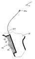
- FIG. 1shows a typical conventional trigger assembly for a mobile terminal.
- the assemblyconsists of several mechanical type components that are utilized to actuate electrical switch assembly 8 upon the depression of a trigger button 4 .
- Switch assembly 8has two switch elements 8 a and 8 b to activate two functions on the mobile terminal.
- Switch assembly 8can include contacts 5 or wires/flex that connect to circuitry within the mobile terminal.
- a trigger housing 9connects trigger button 4 with mobile terminal housing 10 .
- a trigger bezel 6connects trigger button 4 with trigger housing 9 .
- a leaf spring 3acts to restore trigger button 4 to its initial position after trigger button 4 is depressed. Sealing in terms of electrostatic discharge (ESD), water, and dust, requires the addition of gaskets to the trigger assembly.
- ESDelectrostatic discharge
- the above-described trigger assemblyhas a number of shortcomings.
- the trigger assemblyrequires a user to assert a fixed amount of force and stroke in order to activate the trigger.
- the trigger assemblymust include gaskets to environmentally seal the terminal. Even with such gaskets, water and debris may still enter the terminal.
- the trigger assemblyhas a limited number of life cycles due to wear on the various moving parts.
- the trigger assemblyrequires a relatively significant amount of labor to manufacture.
- the trigger assemblyincludes a pressure sensitive member and a trigger button.
- the pressure sensitive memberis secured to a portion of the mobile terminal.
- the trigger buttonis secured to the mobile terminal in a manner such that a force applied to the trigger button causes a resultant force to be applied on the pressure sensitive member.
- the pressure sensitive memberincludes a connector that is coupled to circuitry on the mobile terminal.
- asserting a force on the trigger buttonchanges electronic properties of the pressure sensitive member.
- asserting a force on the trigger buttoncauses a change in the electrical resistance the pressure sensitive member.
- the forcecauses a conductive layer of the pressure sensitive member to come in contact with conductive traces within the pressure sensitive member. As the force increases (within a certain range), the electrical resistance of the conductive traces decreases.
- asserting a force on the trigger buttoncauses a change in the capacitance of the pressure sensitive member.
- a piezoelectric elementis included in the pressure sensitive member wherein when pressure is applied to the pressure sensitive member there is a change in potential between the opposite sides of piezoelectric element.
- At least a portion of the pressure sensitive memberis insert molded into the mobile terminal housing, creating an integral seal.
- the triggering systemincludes a user force adjustment feature wherein a user can adjust the amount of force required to activate the trigger.
- the triggering systemincludes a user position adjustment feature, wherein a user can adjust the number of trigger positions, i.e., 1, 2, or 3 positions, for activation of several different features.
- the triggering systemincludes a pressure sensitive member that includes multiple pressure sensitive target areas which would enable a user to activate several different features by depressing different areas of the trigger.
- the triggering systemincludes a tactile or audio feedback mechanism.
- FIG. 1shows a conventional trigger assembly used in a mobile terminal
- FIG. 2shows an exemplary embodiment of a trigger assembly according to the present invention including a portion of a housing of a mobile terminal
- FIG. 3shows an exploded view of a trigger assembly of a preferred embodiment of the present invention
- FIG. 4shows a pressure sensitive member of a preferred embodiment of the present invention
- FIG. 5shows a side view of an alternative embodiment of the pressure sensitive member of the present invention
- FIG. 6shows another alternative embodiment of the pressure sensitive member of the present invention.
- FIG. 7shows a side view of an alternative embodiment of the pressure sensitive member of the present invention.
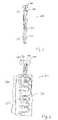
- FIG. 2shows a portion of a mobile terminal housing 10 having a triggering assembly according to the present invention.
- FIG. 3shows an exploded view of the trigger assembly.
- the triggering assemblyincludes a trigger button 14 and a pressure sensitive member 20 .
- a trigger housing 19connects trigger button 14 with mobile terminal housing 10 .
- Trigger housing 19is preferable comprised of a rubber over mold.
- Trigger button 14is secured to trigger housing 19 via an interface fit or other fastening techniques known to those of skill in the art.
- Trigger button 14includes a front section 17 for engagement with one or more of the user's fingers. Opposite front section 17 of trigger button 14 is a back section 18 .
- trigger button 14When a user engages trigger button 14 , back section 18 asserts a force on trigger housing 19 which asserts a force on a target area 22 of pressure sensitive member 20 .
- the trigger buttoncould directly assert the force on the target area of the pressure sensitive member.
- pressure sensitive member 20is insert molded into mobile terminal housing 10 .
- the techniques for molding pressure sensitive member 20 into mobile terminal housing 10are those traditionally used in the plastic molding industry.
- the molded trigger assembly of the present inventionis more environmentally sealed than traditional triggering assemblies that tend to rely on elastic gaskets. Gaskets may allow the passage of water and debris into the mobile terminal and eventually wear after repeated use.
- tooling parts to manufacture the gaskets and labor costs to install the gasketsare eliminated under the present invention.
- an adhesive materialis applied between pressure sensitive member 20 and mobile terminal housing 10 to secure the two components.
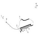
- FIG. 4shows an exemplary embodiment of pressure sensitive member 20 according to the present invention.
- Target area 22 of pressure sensitive member 20is connected to flexible tail 24 .
- Flexible tail 24is connected to a connector 26 .
- Connector 26electrically couples pressure sensitive member 20 to a circuitry on the mobile terminal.
- Connector 26includes two contacts, 31 and 32 , that interface with contacts within the mobile terminal. Electrically connected to contacts 31 and 32 within pressure sensitive member 20 are, respectively, conductive traces 35 and 36 . Within target area 22 , conductive traces 35 and 36 are arranged in a pattern that covers a substantial portion of the surface area of target area 22 . Preferably, conductive traces 35 and 36 are arranged in a zigzag pattern. One skilled in the art would recognize that the conductive traces could be configured in a number of different patterns without departing from the nature of the present invention. Conductive traces 35 and 36 terminate at a distal end of pressure sensitive member 20 .
- Pressure sensitive member 20includes a conductive layer 37 in longitudinal relation to conductive traces 35 and 36 .
- Conductive lay 37may be located either under and/or over conductive traces 35 and 36 .
- Conductive layer 37could be comprised of a number of different conductive materials.
- conductive layer 37is comprised of conductive rubber.
- Pressure sensitive member 20is configured such that when there is no pressure applied on it, no electric current (or very little current) will flow between conductive trace 35 and conductive trace 36 . As pressure is applied to pressure sensitive member 20 , conductive layer 37 comes in contact with conductive traces 35 and 36 . Thus, conductive layer 37 enables an electric current to flow between conductive trace 35 and conductive trace 36 .
- Connector 26is fastened to a terminal connector 7 within the mobile terminal.
- Circuitry within the mobile terminalmeasures the current between conductive traces 35 and 36 .
- the measured currentis compared to a threshold value. If the measured current between conductive traces 35 and 36 is more than the threshold value, a certain function of the mobile terminal is activated. For instance, if the measured current exceeds the threshold value, the mobile terminal will scan a bar code with a laser-based scanner, take an image using an imaging module, activate a microphone on a telephonic communication module or send data over a wireless network. If the measured current is less than the threshold value, the functionality of the mobile terminal will not be activated.
- different functions of the mobile terminalcan be activated depending on the amount of force a user applies to the trigger button 14 . For instance, if the measured current between conductive traces 35 and 36 is between an initial threshold and a second threshold, a first function of the mobile terminal is activated. In the event the measured current between conductive traces 35 and 36 is between the second threshold and a third threshold, a second function of the mobile terminal is activated. In a similar manner, the system could be designed to activate more than two functions of the mobile terminal.
- FIG. 7shows a side view of an alternative embodiment of pressure sensitive member 20 of the present invention.
- Pressure sensitive member 20includes a dialectic material 50 .
- First conductive layer 62 and second conductive layer 64are connected, respectively, to conductive traces 68 and 66 .
- Conductive trace 66is connected to contact 31 .
- Conductive trace 68is connected to contact 32 (not shown in FIG. 7 ).
- the capacitance measured between contacts 31 and 32changes.
- the change in capacitancecan be measured at contacts 31 and 32 to detect the amount of force asserted on pressure sensitive member 20 .
- the measured change in capacitance between contacts 31 and 32is compared to a threshold value. In a manner similar to the embodiment described above, if the measured current between contacts 31 and 32 is more than the threshold value, a certain function of the mobile terminal is activated.
- the amount of force required to activate a function of the mobile terminalis user adjustable. Preferably, this is accomplished by adjusting the threshold value necessary to activate the function of the mobile terminal.
- a user who wants to change the sensitivity of the triggercan put the mobile device in trigger adjustment mode. This may be done via a user interface, e.g., a touch screen display.
- the usersets the threshold value by putting the mobile device in the trigger adjustment mode and pressing the trigger. The amount of force the user asserts is used to set the threshold value.
- the usercan adjust the threshold value by scanning barcodes dedicated to that function.
- a user manual for the mobile terminalcould include trigger force adjustment barcodes that correspond to light force, medium force and heavy force. The user could simply scan the barcode that corresponds to the setting preferred by the user.
- the systemautomatically sets the threshold value to that user's preferred, preset threshold setting.
- the mobile terminalaccesses a database (located either remotely or locally) that matches the user identification codes to a preferred threshold setting. After the user enters his or her identification code, the system determines the correct threshold value and sets it for that particular user.
- FIG. 5shows a side view of an alternative embodiment of pressure sensitive member 20 of the present invention that includes piezoelectric components.
- Pressure sensitive member 20includes a piezoelectric component such as a piezoceramic 50 .
- a piezoelectric componentsuch as a piezoceramic 50 .
- First conductive layer 52 and second conductive layer 54are connected, respectively, to conductive traces 58 and 56 .
- Conductive trace 56is connected to contact 31 .
- Conductive trace 58is connected to contact 32 (not shown in FIG. 5 ).
- the change in potentialcan be measured at contacts 31 and 32 to detect the amount of force asserted on pressure sensitive member 20 .
- the measured change in potential between contacts 31 and 32is compared to a threshold value. In a manner similar to the embodiment described above, if the measured current between contacts 31 and 32 is more than the threshold value, a certain function of the mobile terminal is activated.
- FIG. 6shows an embodiment of pressure sensitive member 20 having two pressure sensitive target areas 22 a and 22 b .
- This embodimentis used to activate multiple functions of the mobile terminal.
- a forceis applied to target area 22 a activating a particular function of the mobile terminal.
- a forceis applied to target area 22 b activating another function of the mobile terminal.
- This embodiment of the inventionoperates in a manner similar to that described above except that there are two pairs of conductive traces, 35 a , 36 a and 35 b , 36 b , and two pairs of contacts 31 a , 32 b and 31 b and 32 b .
- a force applied to target area 22 ais detected by measuring the current between 32 a and 31 a .
- a force applied to target area 22 bis detected by measuring the current between 32 b and 31 b .
- pressure sensitive member 20could have more than two pressure sensitive target areas.
- One skilled in the artwould recognize that the multiple pressure sensitive mode described herein could also be accomplished by using piezoceramic elements with pressure sensitive member 20 in a manner similar to that described above.
- the functions activated on the mobile terminalcould be initiated depending on a combination of the user's finger assertions.
- the pressure sensitive member 20includes three target areas, T 1 , T 2 and T 3 .
- a particular functione.g., F 1 , F 2 or F 3
- F 4forces are asserted simultaneously on T 1 and T 2
- F 4the assertion of forces simultaneously on T 1 and T 3
- F 5the assertion of forces simultaneously on T 1 and T 3 could result in a fifth function, F 5 , could be initiated.
- each target areacould activate multiple functions depending upon the amount for force applied to the target area.
- the functionality of the mobile terminalcould be controlled in a manner analogous to a musical instrument. While it is recognized that it may take a great deal of practice to become proficient at applying the various combinations of forces and/or amounts of forces on the trigger button, the benefits are significant.
- the user of a mobile device that has multiple functionscan activate multiple functions in an instant with a single hand.
- the trigger assemblyincludes a tactile feedback mechanism. After the amount of force asserted on the trigger button exceeds the threshold value, the tactile feedback mechanism creates a slight movement in the trigger button to allow a user to feel that the trigger assembly was properly engaged.
- the tactile feedback in the trigger buttoncould be created by a small solenoid or spring within the trigger assembly.
- the trigger assemblyincludes an audio feedback mechanism.
- the audio feedbackcould be generated within a speaker on the mobile terminal.
- the speakeris the main speaker used in the mobile terminal.
- the systemsends an audio signal to the speaker.
- the sound from the speakeris user selectable. The user can select from a list of sounds that he or she would like the terminal to make in response to a trigger actuation.
- the trigger assemblycould be configured so that the speaker makes different sounds depending upon the function by activated.
- the embodiments described aboveare described with respect to a trigger button on a handle on a mobile terminal. It should be recognized that the trigger assembly of the present invention could be located on other areas of the mobile terminal. For instance, the trigger button could be located on the side or face of the mobile terminal.
Landscapes
- Engineering & Computer Science (AREA)
- Theoretical Computer Science (AREA)
- General Engineering & Computer Science (AREA)
- Physics & Mathematics (AREA)
- General Physics & Mathematics (AREA)
- Human Computer Interaction (AREA)
- Electromagnetism (AREA)
- Health & Medical Sciences (AREA)
- General Health & Medical Sciences (AREA)
- Toxicology (AREA)
- Artificial Intelligence (AREA)
- Computer Vision & Pattern Recognition (AREA)
- Telephone Set Structure (AREA)
- Telephone Function (AREA)
Abstract
Description
Claims (19)
Priority Applications (2)
| Application Number | Priority Date | Filing Date | Title |
|---|---|---|---|
| US11/381,558US7306156B2 (en) | 2002-06-03 | 2006-05-04 | Re-configurable trigger assembly |
| US11/950,953US7481372B2 (en) | 2002-06-03 | 2007-12-05 | Re-configurable trigger assembly |
Applications Claiming Priority (2)
| Application Number | Priority Date | Filing Date | Title |
|---|---|---|---|
| US10/160,772US7055749B2 (en) | 2002-06-03 | 2002-06-03 | Re-configurable trigger assembly |
| US11/381,558US7306156B2 (en) | 2002-06-03 | 2006-05-04 | Re-configurable trigger assembly |
Related Parent Applications (1)
| Application Number | Title | Priority Date | Filing Date |
|---|---|---|---|
| US10/160,772ContinuationUS7055749B2 (en) | 2002-06-03 | 2002-06-03 | Re-configurable trigger assembly |
Related Child Applications (1)
| Application Number | Title | Priority Date | Filing Date |
|---|---|---|---|
| US11/950,953ContinuationUS7481372B2 (en) | 2002-06-03 | 2007-12-05 | Re-configurable trigger assembly |
Publications (2)
| Publication Number | Publication Date |
|---|---|
| US20060186207A1 US20060186207A1 (en) | 2006-08-24 |
| US7306156B2true US7306156B2 (en) | 2007-12-11 |
Family
ID=29731921
Family Applications (3)
| Application Number | Title | Priority Date | Filing Date |
|---|---|---|---|
| US10/160,772Expired - LifetimeUS7055749B2 (en) | 2002-06-03 | 2002-06-03 | Re-configurable trigger assembly |
| US11/381,558Expired - LifetimeUS7306156B2 (en) | 2002-06-03 | 2006-05-04 | Re-configurable trigger assembly |
| US11/950,953Expired - LifetimeUS7481372B2 (en) | 2002-06-03 | 2007-12-05 | Re-configurable trigger assembly |
Family Applications Before (1)
| Application Number | Title | Priority Date | Filing Date |
|---|---|---|---|
| US10/160,772Expired - LifetimeUS7055749B2 (en) | 2002-06-03 | 2002-06-03 | Re-configurable trigger assembly |
Family Applications After (1)
| Application Number | Title | Priority Date | Filing Date |
|---|---|---|---|
| US11/950,953Expired - LifetimeUS7481372B2 (en) | 2002-06-03 | 2007-12-05 | Re-configurable trigger assembly |
Country Status (1)
| Country | Link |
|---|---|
| US (3) | US7055749B2 (en) |
Cited By (4)
| Publication number | Priority date | Publication date | Assignee | Title |
|---|---|---|---|---|
| US20080110737A1 (en)* | 2006-11-14 | 2008-05-15 | Chun-Hsien Chen | Trigger Device Used In A Palmtop Computer |
| US20100258631A1 (en)* | 2009-04-09 | 2010-10-14 | Metrologic Instruments, Inc. | Trigger Mechanism for Hand Held Devices |
| US8424766B2 (en) | 2009-11-04 | 2013-04-23 | Hand Held Products, Inc. | Support assembly for terminal |
| US20170092442A1 (en)* | 2015-09-29 | 2017-03-30 | Datalogic Ip Tech S.R.L. | Modular trigger assembly |
Families Citing this family (34)
| Publication number | Priority date | Publication date | Assignee | Title |
|---|---|---|---|---|
| US6999797B2 (en)* | 2002-06-11 | 2006-02-14 | Symbol Technologies, Inc. | Handle grip for a mobile terminal |
| US7080787B2 (en)* | 2003-07-03 | 2006-07-25 | Symbol Technologies, Inc. | Insert molded antenna |
| US20060208086A1 (en)* | 2005-03-15 | 2006-09-21 | Psc Scanning, Inc. | Multifunction trigger for RFID and optical readers |
| USD539294S1 (en)* | 2005-09-14 | 2007-03-27 | Symbol Technologies, Inc. | Mobile device handle |
| US7497382B2 (en)* | 2005-11-29 | 2009-03-03 | Symbol Technologies, Inc. | Method of and control switch arrangement for controlling different operational states in an electro-optical reader |
| USD558206S1 (en)* | 2006-01-09 | 2007-12-25 | Optoelectronics Co., Ltd. | Handheld scanner |
| USD540333S1 (en)* | 2006-01-17 | 2007-04-10 | Symbol Technologies, Inc. | Mobile device handle |
| USD558768S1 (en)* | 2006-03-30 | 2008-01-01 | Symbol Technologies, Inc. | Mobile device handle |
| US20080148523A1 (en)* | 2006-09-28 | 2008-06-26 | Macgregor Shane | Mobile device with handle |
| US20090108075A1 (en)* | 2007-10-31 | 2009-04-30 | Igor Vinogradov | Sealed housing with integral window and integral pressure indicator in electro-optical reader |
| CA127025S (en)* | 2008-07-25 | 2009-07-17 | Psion Teklogix Inc | Handle for hand held computer |
| US7857226B2 (en)* | 2008-07-28 | 2010-12-28 | Psion Teklogix Inc. | Actuation mechanism for a pistol grip having multiple actuation positions regions |
| USD612858S1 (en)* | 2009-05-27 | 2010-03-30 | Kevin Arnold | Hand held scanner |
| US8814049B2 (en) | 2009-06-18 | 2014-08-26 | Bluebird Soft Co., Ltd. | Mobile terminal having information recognition module |
| JP5304544B2 (en)* | 2009-08-28 | 2013-10-02 | ソニー株式会社 | Information processing apparatus, information processing method, and program |
| US20110107643A1 (en)* | 2009-11-06 | 2011-05-12 | Magpul Industries Corporation | Ergonomic Firearm Fore Grip |
| US8210437B2 (en)* | 2010-03-04 | 2012-07-03 | Symbol Technologies, Inc. | Data capture terminal with automatic focusing over a limited range of working distances |
| USD633095S1 (en)* | 2010-04-26 | 2011-02-22 | Psion Teklogix Inc | Pistol grip for handheld computer |
| US8451104B2 (en) | 2010-05-25 | 2013-05-28 | Motorola Mobility Llc | Passive user input attachment engaging compressible conductive elements and method for using the same |
| KR101107016B1 (en)* | 2010-09-02 | 2012-01-25 | (주)블루버드 소프트 | Mobile terminal |
| US8479993B2 (en) | 2011-07-29 | 2013-07-09 | Symbol Technologies, Inc. | Method for aiming imaging scanner with single trigger |
| US8910863B2 (en)* | 2013-01-05 | 2014-12-16 | Otter Products, Llc | Electronic device case for mobile point of sale |
| US9696111B2 (en) | 2014-08-26 | 2017-07-04 | Fxd, Llc | Auxiliary device mounting system for firearms |
| USD745629S1 (en) | 2014-08-29 | 2015-12-15 | Magpul Industries Corporation | Firearm fore grip |
| US9117129B1 (en) | 2015-02-05 | 2015-08-25 | Symbol Technologies, Llc | Predictive triggering in an electronic device |
| US9576173B1 (en)* | 2015-11-20 | 2017-02-21 | Symbol Technologies, Llc | Methods and systems for a bind free pivoting trigger mechanism |
| US9792478B2 (en) | 2015-11-20 | 2017-10-17 | Symbol Technologies, Llc | Methods and systems for a bind free pivoting trigger mechanism |
| USD803969S1 (en)* | 2016-02-29 | 2017-11-28 | Fxd, Llc | Angled grip |
| JP6323960B2 (en)* | 2016-08-02 | 2018-05-16 | 本田技研工業株式会社 | Input device |
| US20180068145A1 (en)* | 2016-09-07 | 2018-03-08 | Hand Held Products, Inc. | Smart scan peripheral |
| US11441870B2 (en)* | 2019-10-18 | 2022-09-13 | James Matthew Underwood | Forward brace assembly |
| USD1013818S1 (en)* | 2022-07-15 | 2024-02-06 | Colby David Parrish | Curved firearm grip |
| USD975817S1 (en)* | 2022-07-15 | 2023-01-17 | Colby David Parrish | Flat vertical firearm grip |
| USD1013820S1 (en)* | 2022-12-21 | 2024-02-06 | Colby David Parrish | Curved firearm grip |
Citations (26)
| Publication number | Priority date | Publication date | Assignee | Title |
|---|---|---|---|---|
| US4430526A (en) | 1982-01-25 | 1984-02-07 | Bell Telephone Laboratories, Incorporated | Interactive graphics transmission system employing an adaptive stylus for reduced bandwidth |
| US5369262A (en) | 1992-06-03 | 1994-11-29 | Symbol Technologies, Inc. | Electronic stylus type optical reader |
| US5600105A (en)* | 1993-12-28 | 1997-02-04 | Wacom Co., Ltd. | Position detecting device and position pointing device therefor |
| US5606614A (en)* | 1993-10-15 | 1997-02-25 | British Telecommunications Public Limited Company | Personal identification systems |
| US5610386A (en)* | 1995-07-17 | 1997-03-11 | Symbol Technologies, Inc. | Portable optical scanning system including ring having breakaway element |
| US5656805A (en)* | 1990-11-15 | 1997-08-12 | Geo Labs, Inc. | Light beam scanning pen, scan module for the device and method of utilization |
| US5689285A (en) | 1993-09-13 | 1997-11-18 | Asher; David J. | Joystick with membrane sensor |
| US5997996A (en) | 1996-03-27 | 1999-12-07 | A-Plus Corporation | Sheet-like pressure-sensitive resistance member having electrodes, method of making the same, and sheet-like pressure-sensitive resistance member |
| US6057554A (en) | 1997-05-12 | 2000-05-02 | Plesko; George A. | Reflective switch |
| US6264108B1 (en) | 1998-06-08 | 2001-07-24 | International Business Machines Corporation | Protection of sensitive information contained in integrated circuit cards |
| US20010011276A1 (en)* | 1997-05-07 | 2001-08-02 | Robert T. Durst Jr. | Scanner enhanced remote control unit and system for automatically linking to on-line resources |
| US6275138B1 (en) | 1999-06-10 | 2001-08-14 | Alps Electric Co., Ltd. | Variable resistor changing resistance value by pressing |
| US20010017592A1 (en)* | 1998-09-04 | 2001-08-30 | Armstrong Brad A. | Remote controller with analog pressure sensor (S) |
| US6313731B1 (en) | 2000-04-20 | 2001-11-06 | Telefonaktiebolaget L.M. Ericsson | Pressure sensitive direction switches |
| US20020020749A1 (en)* | 2000-08-11 | 2002-02-21 | Alps Electric Co., Ltd. | Controller capable of operating plural operation objects by switching display of operation surface of operation member |
| US6357662B1 (en) | 1996-01-02 | 2002-03-19 | Intermec Ip Corp. | Hand-held, dual-mode asset tracking reader with light-activated switch |
| US6373373B1 (en) | 1999-12-06 | 2002-04-16 | Alps Electric Co., Ltd. | Electronic pressure-sensitive device for detecting the magnitude of load as electrical resistance |
| US6388556B1 (en) | 2000-09-07 | 2002-05-14 | Fujikura Ltd. | Film pressure sensitive resistor and pressure sensitive sensor |
| US6420974B1 (en) | 1998-09-18 | 2002-07-16 | Honeywell Data Instruments Inc. | Control system for pressure-sensitive protective devices |
| US6420956B1 (en) | 2000-07-31 | 2002-07-16 | Alps Electric Co., Ltd. | Detection device in which output varies with amount by which elastically deformable contact element is pressed |
| US6446871B1 (en) | 1997-12-19 | 2002-09-10 | A.T. Cross Company | Method and apparatus for storing reference codes in a writing instrument and for retrieving information identifed by the reference codes |
| US6450046B1 (en) | 1999-10-22 | 2002-09-17 | Matsushita Electric Industrial Co., Ltd. | Pressure sensitive switch and seating detector having the same |
| US6466198B1 (en) | 1999-11-05 | 2002-10-15 | Innoventions, Inc. | View navigation and magnification of a hand-held device with a display |
| US6478225B1 (en)* | 1988-10-21 | 2002-11-12 | Symbol Technologies, Inc. | Adaptive bar code scanner |
| US6563415B2 (en) | 1996-07-05 | 2003-05-13 | Brad A. Armstrong | Analog sensor(s) with snap-through tactile feedback |
| US6878865B1 (en)* | 2003-01-31 | 2005-04-12 | Pioneer Hi-Bred International, Inc. | Inbred maize line PHB5R |
Family Cites Families (2)
| Publication number | Priority date | Publication date | Assignee | Title |
|---|---|---|---|---|
| US6677929B2 (en)* | 2001-03-21 | 2004-01-13 | Agilent Technologies, Inc. | Optical pseudo trackball controls the operation of an appliance or machine |
| JP4260406B2 (en)* | 2002-02-14 | 2009-04-30 | 富士通コンポーネント株式会社 | Pressing direction detection sensor and input device using the same |
- 2002
- 2002-06-03USUS10/160,772patent/US7055749B2/ennot_activeExpired - Lifetime
- 2006
- 2006-05-04USUS11/381,558patent/US7306156B2/ennot_activeExpired - Lifetime
- 2007
- 2007-12-05USUS11/950,953patent/US7481372B2/ennot_activeExpired - Lifetime
Patent Citations (26)
| Publication number | Priority date | Publication date | Assignee | Title |
|---|---|---|---|---|
| US4430526A (en) | 1982-01-25 | 1984-02-07 | Bell Telephone Laboratories, Incorporated | Interactive graphics transmission system employing an adaptive stylus for reduced bandwidth |
| US6478225B1 (en)* | 1988-10-21 | 2002-11-12 | Symbol Technologies, Inc. | Adaptive bar code scanner |
| US5656805A (en)* | 1990-11-15 | 1997-08-12 | Geo Labs, Inc. | Light beam scanning pen, scan module for the device and method of utilization |
| US5369262A (en) | 1992-06-03 | 1994-11-29 | Symbol Technologies, Inc. | Electronic stylus type optical reader |
| US5689285A (en) | 1993-09-13 | 1997-11-18 | Asher; David J. | Joystick with membrane sensor |
| US5606614A (en)* | 1993-10-15 | 1997-02-25 | British Telecommunications Public Limited Company | Personal identification systems |
| US5600105A (en)* | 1993-12-28 | 1997-02-04 | Wacom Co., Ltd. | Position detecting device and position pointing device therefor |
| US5610386A (en)* | 1995-07-17 | 1997-03-11 | Symbol Technologies, Inc. | Portable optical scanning system including ring having breakaway element |
| US6357662B1 (en) | 1996-01-02 | 2002-03-19 | Intermec Ip Corp. | Hand-held, dual-mode asset tracking reader with light-activated switch |
| US5997996A (en) | 1996-03-27 | 1999-12-07 | A-Plus Corporation | Sheet-like pressure-sensitive resistance member having electrodes, method of making the same, and sheet-like pressure-sensitive resistance member |
| US6563415B2 (en) | 1996-07-05 | 2003-05-13 | Brad A. Armstrong | Analog sensor(s) with snap-through tactile feedback |
| US20010011276A1 (en)* | 1997-05-07 | 2001-08-02 | Robert T. Durst Jr. | Scanner enhanced remote control unit and system for automatically linking to on-line resources |
| US6057554A (en) | 1997-05-12 | 2000-05-02 | Plesko; George A. | Reflective switch |
| US6446871B1 (en) | 1997-12-19 | 2002-09-10 | A.T. Cross Company | Method and apparatus for storing reference codes in a writing instrument and for retrieving information identifed by the reference codes |
| US6264108B1 (en) | 1998-06-08 | 2001-07-24 | International Business Machines Corporation | Protection of sensitive information contained in integrated circuit cards |
| US20010017592A1 (en)* | 1998-09-04 | 2001-08-30 | Armstrong Brad A. | Remote controller with analog pressure sensor (S) |
| US6420974B1 (en) | 1998-09-18 | 2002-07-16 | Honeywell Data Instruments Inc. | Control system for pressure-sensitive protective devices |
| US6275138B1 (en) | 1999-06-10 | 2001-08-14 | Alps Electric Co., Ltd. | Variable resistor changing resistance value by pressing |
| US6450046B1 (en) | 1999-10-22 | 2002-09-17 | Matsushita Electric Industrial Co., Ltd. | Pressure sensitive switch and seating detector having the same |
| US6466198B1 (en) | 1999-11-05 | 2002-10-15 | Innoventions, Inc. | View navigation and magnification of a hand-held device with a display |
| US6373373B1 (en) | 1999-12-06 | 2002-04-16 | Alps Electric Co., Ltd. | Electronic pressure-sensitive device for detecting the magnitude of load as electrical resistance |
| US6313731B1 (en) | 2000-04-20 | 2001-11-06 | Telefonaktiebolaget L.M. Ericsson | Pressure sensitive direction switches |
| US6420956B1 (en) | 2000-07-31 | 2002-07-16 | Alps Electric Co., Ltd. | Detection device in which output varies with amount by which elastically deformable contact element is pressed |
| US20020020749A1 (en)* | 2000-08-11 | 2002-02-21 | Alps Electric Co., Ltd. | Controller capable of operating plural operation objects by switching display of operation surface of operation member |
| US6388556B1 (en) | 2000-09-07 | 2002-05-14 | Fujikura Ltd. | Film pressure sensitive resistor and pressure sensitive sensor |
| US6878865B1 (en)* | 2003-01-31 | 2005-04-12 | Pioneer Hi-Bred International, Inc. | Inbred maize line PHB5R |
Cited By (8)
| Publication number | Priority date | Publication date | Assignee | Title |
|---|---|---|---|---|
| US20080110737A1 (en)* | 2006-11-14 | 2008-05-15 | Chun-Hsien Chen | Trigger Device Used In A Palmtop Computer |
| US8134430B2 (en)* | 2006-11-14 | 2012-03-13 | Unitech Electronics Co., Ltd. | Trigger device used in a palmtop computer |
| US20100258631A1 (en)* | 2009-04-09 | 2010-10-14 | Metrologic Instruments, Inc. | Trigger Mechanism for Hand Held Devices |
| US8424768B2 (en) | 2009-04-09 | 2013-04-23 | Metrologic Instruments, Inc. | Trigger mechanism for hand held devices |
| US9224551B2 (en) | 2009-04-09 | 2015-12-29 | Metrologic Instruments, Inc. | Trigger mechanism for hand held devices |
| US8424766B2 (en) | 2009-11-04 | 2013-04-23 | Hand Held Products, Inc. | Support assembly for terminal |
| US20170092442A1 (en)* | 2015-09-29 | 2017-03-30 | Datalogic Ip Tech S.R.L. | Modular trigger assembly |
| US10049831B2 (en)* | 2015-09-29 | 2018-08-14 | Datalogic Ip Tech S.R.L. | Modular trigger assembly |
Also Published As
| Publication number | Publication date |
|---|---|
| US20030234291A1 (en) | 2003-12-25 |
| US20060186207A1 (en) | 2006-08-24 |
| US7481372B2 (en) | 2009-01-27 |
| US20080164318A1 (en) | 2008-07-10 |
| US7055749B2 (en) | 2006-06-06 |
Similar Documents
| Publication | Publication Date | Title |
|---|---|---|
| US7306156B2 (en) | Re-configurable trigger assembly | |
| US11425480B2 (en) | User input element | |
| US6760015B2 (en) | Double-sided keyboard for use in an electronic device | |
| US6787865B2 (en) | Pressing direction sensor and input device using the same | |
| US6630925B1 (en) | Double-sided keyboard having two keymats and one activation mat | |
| CN100545977C (en) | Switching device | |
| US8674941B2 (en) | Systems and methods for implementing haptics for pressure sensitive keyboards | |
| US5357062A (en) | Pressure sensing apparatus for digitizer pen tip | |
| US20110095877A1 (en) | Apparatus and methods for mounting haptics actuation circuitry in keyboards | |
| US7952038B1 (en) | Two-stage switch apparatus | |
| EP2096521A1 (en) | Direction input device | |
| EP1877961A1 (en) | Signaling pen | |
| WO2006067911A1 (en) | Direction detection switch | |
| US6933925B1 (en) | Computer mouse with elastomeric dome switch | |
| KR101478894B1 (en) | Passive user input attachments engaging compressible conductive elements and method for the same | |
| WO2025031278A1 (en) | Switching apparatus and electronic device | |
| US7191662B2 (en) | Polymer-based sensor apparatus and method | |
| CN106452417A (en) | Static capacitance switch button and static capacitance keyboard with adjustable trigger stroke | |
| KR20150031968A (en) | Terminal | |
| JP2002157063A (en) | Multi-directional switch system for electronic equipment, and electronic equipment using the same | |
| KR102187092B1 (en) | Gesture detection device using force sensor switch | |
| JPH0448600Y2 (en) | ||
| CN120743139A (en) | Touch pressure detection module and electronic equipment | |
| CN119045766A (en) | Control method of wearable device, wearable device and control method of wearable device | |
| KR20070021632A (en) | Metal dome assembly and signal recognition method using same |
Legal Events
| Date | Code | Title | Description |
|---|---|---|---|
| AS | Assignment | Owner name:SYMBOL TECHNOLOGIES, INC., NEW YORK Free format text:ASSIGNMENT OF ASSIGNORS INTEREST;ASSIGNORS:WULFF, THOMAS;ILKHANOV, AZER;REEL/FRAME:017578/0737 Effective date:20020614 | |
| STCF | Information on status: patent grant | Free format text:PATENTED CASE | |
| FPAY | Fee payment | Year of fee payment:4 | |
| AS | Assignment | Owner name:MORGAN STANLEY SENIOR FUNDING, INC. AS THE COLLATERAL AGENT, MARYLAND Free format text:SECURITY AGREEMENT;ASSIGNORS:ZIH CORP.;LASER BAND, LLC;ZEBRA ENTERPRISE SOLUTIONS CORP.;AND OTHERS;REEL/FRAME:034114/0270 Effective date:20141027 Owner name:MORGAN STANLEY SENIOR FUNDING, INC. AS THE COLLATE Free format text:SECURITY AGREEMENT;ASSIGNORS:ZIH CORP.;LASER BAND, LLC;ZEBRA ENTERPRISE SOLUTIONS CORP.;AND OTHERS;REEL/FRAME:034114/0270 Effective date:20141027 | |
| FPAY | Fee payment | Year of fee payment:8 | |
| AS | Assignment | Owner name:SYMBOL TECHNOLOGIES, LLC, NEW YORK Free format text:CHANGE OF NAME;ASSIGNOR:SYMBOL TECHNOLOGIES, INC.;REEL/FRAME:036083/0640 Effective date:20150410 | |
| AS | Assignment | Owner name:SYMBOL TECHNOLOGIES, INC., NEW YORK Free format text:RELEASE BY SECURED PARTY;ASSIGNOR:MORGAN STANLEY SENIOR FUNDING, INC.;REEL/FRAME:036371/0738 Effective date:20150721 | |
| MAFP | Maintenance fee payment | Free format text:PAYMENT OF MAINTENANCE FEE, 12TH YEAR, LARGE ENTITY (ORIGINAL EVENT CODE: M1553); ENTITY STATUS OF PATENT OWNER: LARGE ENTITY Year of fee payment:12 |