US7305461B2 - Method and system for network management with backup status gathering - Google Patents
Method and system for network management with backup status gatheringDownload PDFInfo
- Publication number
- US7305461B2 US7305461B2US09/737,434US73743400AUS7305461B2US 7305461 B2US7305461 B2US 7305461B2US 73743400 AUS73743400 AUS 73743400AUS 7305461 B2US7305461 B2US 7305461B2
- Authority
- US
- United States
- Prior art keywords
- endpoint
- mission critical
- endpoints
- twin
- discovered
- Prior art date
- Legal status (The legal status is an assumption and is not a legal conclusion. Google has not performed a legal analysis and makes no representation as to the accuracy of the status listed.)
- Expired - Fee Related, expires
Links
- 238000000034methodMethods0.000titleclaimsabstractdescription190
- 230000009471actionEffects0.000claimsabstractdescription107
- 238000012545processingMethods0.000claimsabstractdescription29
- 238000004891communicationMethods0.000claimsabstractdescription24
- 238000004590computer programMethods0.000claimsabstractdescription7
- 238000012544monitoring processMethods0.000claimsdescription39
- 230000004044responseEffects0.000claimsdescription14
- 230000000694effectsEffects0.000abstractdescription21
- 230000008569processEffects0.000description168
- 238000007726management methodMethods0.000description109
- 238000010586diagramMethods0.000description23
- 230000003044adaptive effectEffects0.000description12
- 238000013475authorizationMethods0.000description12
- 230000006870functionEffects0.000description11
- 238000000113differential scanning calorimetryMethods0.000description10
- 230000002085persistent effectEffects0.000description9
- 230000008901benefitEffects0.000description7
- 239000003795chemical substances by applicationSubstances0.000description7
- 230000002688persistenceEffects0.000description7
- 230000008859changeEffects0.000description6
- 238000009434installationMethods0.000description6
- 230000007246mechanismEffects0.000description6
- 238000013459approachMethods0.000description4
- 238000005516engineering processMethods0.000description4
- 230000009467reductionEffects0.000description4
- 238000012423maintenanceMethods0.000description3
- 238000013507mappingMethods0.000description3
- 230000008520organizationEffects0.000description3
- 238000005192partitionMethods0.000description3
- 238000012986modificationMethods0.000description2
- 230000004048modificationEffects0.000description2
- 238000012946outsourcingMethods0.000description2
- 238000011084recoveryMethods0.000description2
- 230000003068static effectEffects0.000description2
- 238000009825accumulationMethods0.000description1
- 239000013543active substanceSubstances0.000description1
- 230000000903blocking effectEffects0.000description1
- 239000000872bufferSubstances0.000description1
- 230000015556catabolic processEffects0.000description1
- 239000000470constituentSubstances0.000description1
- 230000007423decreaseEffects0.000description1
- 238000012217deletionMethods0.000description1
- 230000037430deletionEffects0.000description1
- 230000001419dependent effectEffects0.000description1
- 238000013461designMethods0.000description1
- 238000001514detection methodMethods0.000description1
- 238000011161developmentMethods0.000description1
- 238000001914filtrationMethods0.000description1
- 238000011010flushing procedureMethods0.000description1
- 238000009413insulationMethods0.000description1
- 230000003993interactionEffects0.000description1
- 230000002452interceptive effectEffects0.000description1
- 238000000926separation methodMethods0.000description1
- 238000012795verificationMethods0.000description1
Images


Classifications
- H—ELECTRICITY
- H04—ELECTRIC COMMUNICATION TECHNIQUE
- H04L—TRANSMISSION OF DIGITAL INFORMATION, e.g. TELEGRAPHIC COMMUNICATION
- H04L41/00—Arrangements for maintenance, administration or management of data switching networks, e.g. of packet switching networks
- H04L41/12—Discovery or management of network topologies
- H—ELECTRICITY
- H04—ELECTRIC COMMUNICATION TECHNIQUE
- H04L—TRANSMISSION OF DIGITAL INFORMATION, e.g. TELEGRAPHIC COMMUNICATION
- H04L43/00—Arrangements for monitoring or testing data switching networks
- H04L43/08—Monitoring or testing based on specific metrics, e.g. QoS, energy consumption or environmental parameters
- H04L43/0805—Monitoring or testing based on specific metrics, e.g. QoS, energy consumption or environmental parameters by checking availability
- H04L43/0817—Monitoring or testing based on specific metrics, e.g. QoS, energy consumption or environmental parameters by checking availability by checking functioning
- H—ELECTRICITY
- H04—ELECTRIC COMMUNICATION TECHNIQUE
- H04L—TRANSMISSION OF DIGITAL INFORMATION, e.g. TELEGRAPHIC COMMUNICATION
- H04L41/00—Arrangements for maintenance, administration or management of data switching networks, e.g. of packet switching networks
- H04L41/06—Management of faults, events, alarms or notifications
- H—ELECTRICITY
- H04—ELECTRIC COMMUNICATION TECHNIQUE
- H04L—TRANSMISSION OF DIGITAL INFORMATION, e.g. TELEGRAPHIC COMMUNICATION
- H04L41/00—Arrangements for maintenance, administration or management of data switching networks, e.g. of packet switching networks
- H04L41/50—Network service management, e.g. ensuring proper service fulfilment according to agreements
- H04L41/5003—Managing SLA; Interaction between SLA and QoS
- H04L41/5009—Determining service level performance parameters or violations of service level contracts, e.g. violations of agreed response time or mean time between failures [MTBF]
Definitions
- the present inventionrelates to an improved data processing system and, in particular, to a method and system for multiple computer or network management. Still more particularly, the present invention provides a method and system for computer network monitoring.
- ITinformation technology
- IT solutionsnow require end-to-end management that includes network connectivity, server maintenance, and application management in order to succeed.
- the focus of IT organizationshas turned to ensuring overall service delivery and not just the “towers” of network, server, desktop, and application.
- Management systemsmust fulfill two broad goals: a flexible approach that allows rapid deployment and configuration of new services for the customer; and an ability to support rapid delivery of the management tools themselves.
- a successful management solutionfits into a heterogeneous environment, provides openness with which it can knit together management tools and other types of applications, and a consistent approach to managing all of the IT assets.
- a successful management approachwill also require attention to the needs of the staff within the IT organization to accomplish these goals: the ability of an IT team to deploy an appropriate set of management tasks to match the delegated responsibilities of the IT staff; the ability of an IT team to navigate the relationships and effects of all of their technology assets, including networks, middleware, and applications; the ability of an IT team to define their roles and responsibilities consistently and securely across the various management tasks; the ability of an IT team to define groups of customers and their services consistently across the various management tasks; and the ability of an IT team to address, partition, and reach consistently the managed devices.
- a management systemmust be very resistant to failure so that service attributes, such as response time, uptime, and throughput, are delivered in accordance with guarantees in a service level agreement.
- service attributessuch as response time, uptime, and throughput
- a service providermay attempt to support as many customers as possible within a single network management system.
- the service provider's profit marginsmay materialize from the ability to bill the usage of a common network management system to multiple customers.
- the service providermust be able to support contractual agreements on an individual basis.
- Service attributessuch as response time, uptime, and throughput, must be determinable for each customer.
- a network management systemmust provide a suite of network management tools that is able to perform device monitoring and discovery for each customer's network while integrating these abilities across a shared network backbone to gather the network management information into the service provider's distributed data processing system.
- the management systemcan replicate services, detect faults within a service, restart services, and reassign work to a replicated service.
- the management systemcan replicate services, detect faults within a service, restart services, and reassign work to a replicated service.
- the nodescan be geographically dispersed, and the overall computing environment can be managed in a distributed manner.
- the managed environmentcan be logically separated into a series of loosely connected managed regions, each with its management server for managing local resources.
- the management serverscoordinate activities across the enterprise and permit remote site management and operation. Local resources within one region can be exported for the use of other regions in a variety of manners.
- a mission critical machineshould not be used to monitor a less critical machine because the performance of the mission critical machine is reduced for a non-mission-critical action, which presumably reverses the desired priorities of the service provider.
- a service providerwould rather not burden a mission critical machine with a monitoring operation that is directed to determining the mission critical machine's own status.
- a network management systemallows an administrator to statically define a non-mission critical machine that may be used to monitor a mission critical machine so that the performance of the mission critical machine is not reduced.
- the static assignment processcan be inflexible, and the administrator then has a burden to choose the associations between non-mission-critical machines and mission critical machines.
- a method, system, apparatus, and computer program productare presented for management of a distributed data processing system.
- Resources within the distributed data processing systemare dynamically discovered, and the discovered resources are adaptively monitored using the network management framework.
- a network or system administratorconfigures some mission critical endpoints with multiple network interface cards (NICs) and specifies mission critical endpoints, non-mission critical actions, etc.
- NICsnetwork interface cards
- status collection activities associated with network or system management activitiesthe categorization of an endpoint as a mission-critical or non-mission critical endpoint affects the manner in which the status collection activity is performed.
- Applicationscan request the performance of actions at endpoints without regard to the categorization of the endpoint or without regard to the categorization of the requested action, and the network management system routes the action based on whether or not the specified endpoint is a mission critical endpoint.
- a non-mission-critical endpointis associated with a mission-critical endpoint based on the non-mission-critical endpoint's communication history with the mission critical endpoint.
- the management systemmay use the status of a non-mission-critical endpoint as a reflection of the status of a mission-critical endpoint.
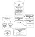
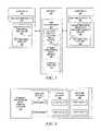
- FIG. 1is a diagram depicting a known logical configuration of software and hardware resources
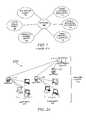
- FIG. 2Ais simplified diagram illustrating a large distributed computing enterprise environment in which the present invention is implemented
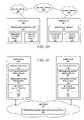
- FIG. 2Bis a block diagram of a preferred system management framework illustrating how the framework functionality is distributed across the gateway and its endpoints within a managed region;
- FIG. 2Cis a block diagram of the elements that comprise the low cost framework (LCF) client component of the system management framework;
- LCFlow cost framework
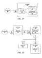
- FIG. 2Dis a diagram depicting a logical configuration of software objects residing within a hardware network similar to that shown in FIG. 2A ;
- FIG. 2Eis a diagram depicting the logical relationships between components within a system management framework that includes two endpoints and a gateway;
- FIG. 2Fis a diagram depicting the logical relationships between components within a system management framework that includes a gateway supporting two DKS-enabled applications;
- FIG. 2Gis a diagram depicting the logical relationships between components within a system management framework that includes two gateways supporting two endpoints;
- FIG. 3is a block diagram depicting components within the system management framework that provide resource leasing management functionality within a distributed computing environment such as that shown in FIGS. 2D-2E ;
- FIG. 4is a block diagram showing data stored by a the IPOP (IP Object Persistence) service
- FIG. 5Ais a block diagram showing the IPOP service in more detail
- FIG. 5Bis a network diagram depicting a set of routers that undergo a scoping process
- FIG. 5Cdepicts the IP Object Security Hierarchy
- FIG. 6is a block diagram showing a set of components that may be used to implement adaptive discovery and adaptive polling in accordance with a preferred embodiment of the present invention
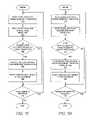
- FIG. 7Ais a flowchart depicting a portion of an initialization process in which a network management system prepares for adaptive discovery and adaptive polling in accordance with a preferred embodiment of the present invention
- FIG. 7Bis a flowchart depicting further detail of the initialization process in which the DSC objects are initially created and stored;
- FIG. 7Cis a flowchart depicting further detail of the initial DSC object creation process in which DSC objects are created and stored for an endpoint/user combination;
- FIG. 7Dis a flowchart depicting further detail of the initial DSC object creation process in which DSC objects are created and stored for an endpoint/endpoint combination;
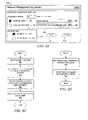
- FIG. 8Adepicts a graphical user interface window that may be used by a network or system administrator to set monitoring parameters for adaptive monitoring associated with users and endpoints in accordance with a preferred embodiment of the present invention
- FIG. 8Bis a flowchart showing a process by which the polling time parameters are set in the appropriate DSC objects after polling time parameters have been specified by an administrator;
- FIG. 8Cis a flowchart showing a process by which a polling time property is added to a DSC after polling time parameters have been specified by an administrator;
- FIG. 8Dis a flowchart showing a process for advertising newly specified polling time properties after polling time parameters have been specified by an administrator
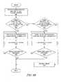
- FIG. 9Ais a flowchart showing a process used by a polling engine to monitor systems within a network after polling time parameters have been specified by an administrator;
- FIG. 9Bis a flowchart showing a process used by a polling engine to get a DSC for a user/endpoint combination
- FIG. 9Cis a flowchart showing a process used by a polling engine to get a DSC for an endpoint/endpoint combination
- FIG. 9Dis a flowchart showing a process used by a polling engine to get a DSC from the DSC manager
- FIG. 9Eis a flowchart showing a process used by a polling engine to queue a polling task.
- FIG. 9Fis a flowchart showing a process used by a polling engine to perform a polling task on an endpoint
- FIG. 10Ais a flowchart showing a process by which an administrator may configure a machine with a twin NIC through a combination of manual and programmatic steps;
- FIG. 10Bis a flowchart showing a process by which a discovery process may be adjusted to detect twin NICs
- FIG. 10Cis a flowchart showing a process by which a polling process may be adjusted when certain endpoints have been categorized as mission critical endpoints;
- FIG. 10Dis a flowchart showing a process by which an application may request an action on a DKS endpoint without regard to whether or not the application is aware of the fact that the endpoint has been categorized as a mission critical endpoint;
- FIG. 10Eis a flowchart showing a process by which the IPOP database performs a search to find an appropriate endpoint against which a requested action should be executed with consideration of whether the endpoint is a mission critical endpoint;
- FIG. 10Fdepicts a graphical user interface window that may be used by a network or system administrator to set assign an endpoint to be used as a mission critical twin endpoint for a mission critical endpoint in accordance with a preferred embodiment of the present invention
- FIGS. 11A-11Eshow some simplified pseudo-code that depicts the manner in which endpoint objects and action objects can be implemented.
- FIGS. 12A-12Bdepict a set of flowcharts that show a process by which a mission-critical-twin endpoint can be located for a mission critical endpoint in accordance with a preferred embodiment of the present invention.
- the present inventionprovides a methodology for managing a distributed data processing system. The manner in which the system management is performed is described further below in more detail after the description of the preferred embodiment of the distributed computing environment in which the present invention operates.
- FIG. 1a diagram depicts a known logical configuration of software and hardware resources.
- the softwareis organized in an object-oriented system.
- Application object 102device driver object 104 , and operating system object 106 communicate across network 108 with other objects and with hardware resources 110 - 114 .
- the objectsrequire some type of processing, input/output, or storage capability from the hardware resources.
- the objectsmay execute on the same device to which the hardware resource is connected, or the objects may be physically dispersed throughout a distributed computing environment.
- the objectsrequest access to the hardware resource in a variety of manners, e.g. operating system calls to device drivers.
- Hardware resourcesare generally available on a first-come, first-serve basis in conjunction with some type of arbitration scheme to ensure that the requests for resources are fairly handled. In some cases, priority may be given to certain requesters, but in most implementations, all requests are eventually processed.
- the present inventionis preferably implemented in a large distributed computer environment 210 comprising up to thousands of “nodes”.
- the nodeswill typically be geographically dispersed and the overall environment is “managed” in a distributed manner.
- the managed environmentis logically broken down into a series of loosely connected managed regions (MRs) 212 , each with its own management server 214 for managing local resources with the managed region.
- the networktypically will include other servers (not shown) for carrying out other distributed network functions. These include name servers, security servers, file servers, thread servers, time servers and the like.
- Multiple servers 214coordinate activities across the enterprise and permit remote management and operation.
- Each server 214serves a number of gateway machines 216 , each of which in turn support a plurality of endpoints/terminal nodes 218 .
- the server 214coordinates all activity within the managed region using a terminal node manager at server 214 .
- each gateway machine 216runs a server component 222 of a system management framework.
- the server component 222is a multi-threaded runtime process that comprises several components: an object request broker (ORB) 221 , an authorization service 223 , object location service 225 and basic object adapter (BOA) 227 .
- Server component 222also includes an object library 229 .
- ORB 221runs continuously, separate from the operating system, and it communicates with both server and client processes through separate stubs and skeletons via an interprocess communication (IPC) facility 219 .
- IPCinterprocess communication
- RPCsecure remote procedure call
- Gateway machine 216also includes operating system 215 and thread mechanism 217 .
- the system management frameworkalso termed distributed kernel services (DKS)
- DKSdistributed kernel services
- the client component 224is a low cost, low maintenance application suite that is preferably “dataless” in the sense that system management data is not cached or stored there in a persistent manner.
- Implementation of the management framework in this “client-server” mannerhas significant advantages over the prior art, and it facilitates the connectivity of personal computers into the managed environment. It should be noted, however, that an endpoint may also have an ORB for remote object-oriented operations within the distributed environment, as explained in more detail further below.
- the system management frameworkfacilitates execution of system management tasks required to manage the resources in the managed region.
- Such tasksare quite varied and include, without limitation, file and data distribution, network usage monitoring, user management, printer or other resource configuration management, and the like.
- the object-oriented frameworkincludes a Java runtime environment for well-known advantages, such as platform independence and standardized interfaces. Both gateways and endpoints operate portions of the system management tasks through cooperation between the client and server portions of the distributed kernel services.
- a server per managed regionthere is preferably one server per managed region with some number of gateways.
- a workgroup-size installatione.g., a local area network
- a single server-class machinemay be used as both a server and a gateway.
- References herein to a distinct server and one or more gateway(s)should thus not be taken by way of limitation as these elements may be combined into a single platform.
- the managed regiongrows breadth-wise, with additional gateways then being used to balance the load of the endpoints.
- the serveris the top-level authority over all gateway and endpoints.
- the servermaintains an endpoint list, which keeps track of every endpoint in a managed region. This list preferably contains all information necessary to uniquely identify and manage endpoints including, without limitation, such information as name, location, and machine type.
- the serveralso maintains the mapping between endpoints and gateways, and this mapping is preferably dynamic.
- a gatewayis a fully managed node that has been configured to operate as a gateway.
- a gatewaymay be regarded as an endpoint.
- a gatewayalways has a network interface card (NIC), so a gateway is also always an endpoint.
- NICnetwork interface card
- a gatewayusually uses itself as the first seed during a discovery process. Initially, a gateway does not have any information about endpoints. As endpoints login, the gateway builds an endpoint list for its endpoints. The gateway's duties preferably include: listening for endpoint login requests, listening for endpoint update requests, and (its main task) acting as a gateway for method invocations on endpoints.
- the endpointis a machine running the system management framework client component, which is referred to herein as a management agent.
- the management agenthas two main parts as illustrated in FIG. 2C : daemon 226 and application runtime library 228 .
- Daemon 226is responsible for endpoint login and for spawning application endpoint executables. Once an executable is spawned, daemon 226 has no further interaction with it. Each executable is linked with application runtime library 228 , which handles all further communication with the gateway.
- each computermay be a RISC System/6000TM (a reduced instruction set or so-called RISC-based workstation) running the AIX (Advanced Interactive Executive) operating system.
- RISC System/6000TMa reduced instruction set or so-called RISC-based workstation
- AIXAdvanced Interactive Executive
- other machines and/or operating systemsmay be used as well for the gateway and server machines.
- Each endpointis also a computing device.
- most of the endpointsare personal computers, e.g., desktop machines or laptops. In this architecture, the endpoints need not be high powered or complex machines or workstations.
- An endpoint computerpreferably includes a Web browser such as Netscape Navigator or Microsoft Internet Explorer. An endpoint computer thus may be connected to a gateway via the Internet, an intranet or some other computer network.
- the client-class framework running on each endpointis a low-maintenance, low-cost framework that is ready to do management tasks but consumes few machine resources because it is normally in an idle state.
- Each endpointmay be “dataless” in the sense that system management data is not stored therein before or after a particular system management task is implemented or carried out.
- FIG. 2Da diagram depicts a logical configuration of software objects residing within a hardware network similar to that shown in FIG. 2A .
- the endpoints in FIG. 2Dare similar to the endpoints shown in FIG. 2B .
- Object-oriented softwaresimilar to the collection of objects shown in FIG. 1 , executes on the endpoints.
- Endpoints 230 and 231support application action object 232 and application object 233 , device driver objects 234 - 235 , and operating system objects 236 - 237 that communicate across a network with other objects and hardware resources.
- Resourcescan be grouped together by an enterprise into managed regions representing meaningful groups. Overlaid on these regions are domains that divide resources into groups of resources that are managed by gateways.
- the gateway machinesprovide access to the resources and also perform routine operations on the resources, such as polling.
- FIG. 2Dshows that endpoints and objects can be grouped into managed regions that represent branch offices 238 and 239 of an enterprise, and certain resources are controlled by in central office 240 . Neither a branch office nor a central office is necessarily restricted to a single physical location, but each represents some of the hardware resources of the distributed application framework, such as routers, system management servers, endpoints, gateways, and critical applications, such as corporate management Web servers. Different types of gateways can allow access to different types of resources, although a single gateway can serve as a portal to resources of different types.
- FIG. 2Ea diagram depicts the logical relationships between components within a system management framework that includes two endpoints and a gateway.
- FIG. 2Eshows more detail of the relationship between components at an endpoint.
- Network 250includes gateway 251 and endpoints 252 and 253 , which contain similar components, as indicated by the similar reference numerals used in the figure.
- An endpointmay support a set of applications 254 that use services provided by the distributed kernel services 255 , which may rely upon a set of platform-specific operating system resources 256 .
- Operating system resourcesmay include TCP/IP-type resources, SNMP-type resources, and other types of resources.
- a subset of TCP/IP-type resourcesmay be a line printer (LPR) resource that allows an endpoint to receive print jobs from other endpoints.
- Applications 254may also provide self-defined sets of resources that are accessible to other endpoints.
- Network device drivers 257send and receive data through NIC hardware 258 to support communication at the endpoint.
- FIG. 2Fa diagram depicts the logical relationships between components within a system management framework that includes a gateway supporting two DKS-enabled applications.
- Gateway 260communicates with network 262 through NIC 264 .
- Gateway 260contains ORB 266 that supports DKS-enabled applications 268 and 269 .
- FIG. 2Fshows that a gateway can also support applications. In other words, a gateway should not be viewed as merely being a management platform but may also execute other types of applications.
- FIG. 2Ga diagram depicts the logical relationships between components within a system management framework that includes two gateways supporting two endpoints.
- Gateway 270communicates with network 272 through NIC 274 .
- Gateway 270contains ORB 276 that may provide a variety of services, as is explained in more detail further below.
- FIG. 2Gshows that a gateway does not necessarily connect with individual endpoints.
- Gateway 270communicates through NIC 278 and network 279 with gateway 280 and its NIC 282 .
- Gateway 280contains ORB 284 for supporting a set of services.
- Gateway 280communicates through NIC 286 and network 287 to endpoint 290 through its NIC 292 and to endpoint 294 through its NIC 296 .
- Endpoint 290contains ORB 298 while endpoint 294 does not contain an ORB.
- FIG. 2Galso shows that an endpoint does not necessarily contain an ORB. Hence, any use of endpoint 294 as a resource is performed solely through management processes at gateway 280 .
- FIGS. 2F and 2Galso depict the importance of gateways in determining routes/data paths within a highly distributed system for addressing resources within the system and for performing the actual routing of requests for resources.
- the importance of representing NICs as objects for an object-oriented routing systemis described in more detail further below.
- a resourceis a portion of a computer system's physical units, a portion of a computer system's logical units, or a portion of the computer system's functionality that is identifiable or addressable in some manner to other physical or logical units within the system.
- a networkcontains gateway 300 and endpoints 301 and 302 .
- Gateway 302runs ORB 304 .
- ORBcan support different services that are configured and run in conjunction with an ORB.
- distributed kernel servicesinclude Network Endpoint Location Service (NELS) 306 , IP Object Persistence (IPOP) service 308 , and Gateway Service 310 .
- the Gateway Serviceprocesses action objects, which are explained in more detail below, and directly communicates with endpoints or agents to perform management operations.
- the gatewayreceives events from resources and passes the events to interested parties within the distributed system.
- the NELSworks in combination with action objects and determines which gateway to use to reach a particular resource.
- a gatewayis determined by using the discovery service of the appropriate topology driver, and the gateway location may change due to load balancing or failure of primary gateways.
- Other resource level servicesmay include an SNMP (Simple Network Management Protocol) service that provides protocol stacks, polling service, and trap receiver and filtering functions.
- the SNMP Servicecan be used directly by certain components and applications when higher performance is required or the location independence provided by the gateways and action objects is not desired.
- a Metadata Servicecan also be provided to distribute information concerning the structure of SNMP agents.
- DKSThe representation of resources within DKS allows for the dynamic management and use of those resources by applications.
- DKSdoes not impose any particular representation, but it does provide an object-oriented structure for applications to model resources.
- object technologyallows models to present a unified appearance to management applications and hide the differences among the underlying physical or logical resources.
- Logical and physical resourcescan be modeled as separate objects and related to each other using relationship attributes.
- a systemmay implement an abstract concept of a router and then use this abstraction within a range of different router hardware.
- the common portionscan be placed into an abstract router class while modeling the important differences in subclasses, including representing a complex system with multiple objects.
- the management applicationsdo not have to handle many details for each managed resource.
- a routerusually has many critical parts, including a routing subsystem, memory buffers, control components, interfaces, and multiple layers of communication protocols.
- Using multiple objectshas the burden of creating multiple object identifiers (OIDs) because each object instance has its own OID.
- OIDsobject identifiers
- a first order objectcan represent the entire resource and contain references to all of the constituent parts.
- Each endpointmay support an object request broker, such as ORBs 320 and 322 , for assisting in remote object-oriented operations within the DKS environment.
- Endpoint 301contains DKS-enabled application 324 that utilizes object-oriented resources found within the distributed computing environment.
- Endpoint 302contains target resource provider object or application 326 that services the requests from DKS-enabled application 324 .
- a set of DKS services 330 and 334support each particular endpoint.
- the communication between a gateway and an action objectis asynchronous, and the action objects provide error handling and recovery. If one gateway goes down or becomes overloaded, another gateway is located for executing the action object, and communication is established again with the application from the new gateway. Once the controlling gateway of the selected endpoint has been identified, the action object will transport itself there for further processing of the command or data contained in the action object. If it is within the same ORB, it is a direct transport. If it is within another ORB, then the transport can be accomplished with a “Moveto” command or as a parameter on a method call.
- Queuing the action object on the gatewayresults in a controlled process for the sending and receiving of data from the IP devices.
- the queued action objectsare executed in the order that they arrive at the gateway.
- the action objectmay create child action objects if the collection of endpoints contains more than a single ORB ID or gateway ID.
- the parent action objectis responsible for coordinating the completion status of any of its children.
- the creation of child action objectsis transparent to the calling application.
- a gatewayprocesses incoming action objects, assigns a priority, and performs additional security challenges to prevent rogue action object attacks.
- the action objectis delivered to the gateway that must convert the information in the action object to a form suitable for the agent.
- the gatewaymanages multiple concurrent action objects targeted at one or more agents, returning the results of the operation to the calling managed object as appropriate.
- potentially leasable target resourcesare Internet protocol (IP) commands, e.g. pings, and Simple Network Management Protocol (SNMP) commands that can be executed against endpoints in a managed region.
- IPInternet protocol
- SNMPSimple Network Management Protocol
- each NIC at a gateway or an endpointmay be used to address an action object.
- Each NICis represented as an object within the IPOP database, which is described in more detail further below.
- the Action Object IP (AOIP) Classis a subclass of the Action Object Class.
- AOIP objectsare the primary vehicle that establishes a connection between an application and a designated IP endpoint using a gateway or stand-alone service.
- Action Object SNMP (AOSnmp) Classis also a subclass of the Action Object Class.
- AOSnmp objectsare the primary vehicle that establishes a connection between an application and a designated SNMP endpoint via a gateway or the Gateway Service.
- the present inventionis primarily concerned with IP endpoints.
- the AOIP classshould include the following: a constructor to initialize itself; an interface to the NELS; a mechanism by which the action object can use the ORB to transport itself to the selected gateway; a mechanism by which to communicate with the SNMP stack in a stand-alone mode; a security check verification of access rights to endpoints; a container for either data or commands to be executed at the gateway; a mechanism by which to pass commands or classes to the appropriate gateway or endpoint for completion; and public methods to facilitate the communication between objects.
- An AOIP objectcreates a logical circuit between an application and the targeted gateway or endpoint. This circuit is persistent until command completion through normal operation or until an exception is thrown.
- the AOIP objectinstantiates itself as an object and initializes any internal variables required.
- An action object IPmay be capable of running a command from inception or waiting for a future command.
- a program that creates an AOIP objectmust supply the following elements: address of endpoints; function to be performed on the endpoint, class, or object; and data arguments specific to the command to be run.
- a small part of the action objectmust contain the return end path for the object. This may identify how to communicate with the action object in case of a breakdown in normal network communications.
- An action objectcan contain either a class or object containing program information or data to be delivered eventually to an endpoint or a set of commands to be performed at the appropriate gateway. Action objects IP return back a result for each address endpoint targeted.
- the AOIP objectuses commands such as “Ping”, “Trace Route”, “Wake-On LAN”, and “Discovery”, the AOIP object performs the following services: facilitates the accumulation of metrics for the user connections; assists in the description of the topology of a connection; performs Wake-On LAN tasks using helper functions; and discovers active agents in the network environment.
- the NELS servicefinds a route (data path) to communicate between the application and the appropriate endpoint.
- the NELS serviceconverts input to protocol, network address, and gateway location for use by action objects.
- the NELS serviceis a thin service that supplies information discovered by the IPOP service.
- the primary roles of the NELS serviceare as follows: support the requests of applications for routes; maintain the gateway and endpoint caches that keep the route information; ensure the security of the requests; and perform the requests as efficiently as possible to enhance performance.
- an applicationrequires a target endpoint (target resource) to be located.
- the targetis ultimately known within the DKS space using traditional network values, i.e. a specific network address and a specific protocol identifier.
- An action objectis generated on behalf of an application to resolve the network location of an endpoint.
- the action objectasks the NELS service to resolve the network address and define the route to the endpoint in that network.
- One of the followingis passed to the action object to specify a destination endpoint: an EndpointAddress object; a fully decoded NetworkAddress object; and a string representing the IP address of the IP endpoint.
- the NELS servicedetermines which gateway to use to reach a particular resource. The appropriate gateway is determined using the discovery service of the appropriate topology driver and may change due to load balancing or failure of primary gateways.
- An “EndpointAddress” objectmust consist of a collection of at least one or more unique managed resource IDs. A managed resource ID decouples the protocol selection process from the application and allows the NELS service to have the flexibility to decide the best protocol to reach an endpoint.
- an “AddressEndpoint” objectis returned, which contains enough information to target the best place to communicate with the selected IP endpoints.
- the addressmay include protocol-dependent addresses as well as protocol-independent addresses, such as the virtual private network id and the IPOP Object ID. These additional addresses handle the case where duplicate addresses exist in the managed region.
- the NELS servicedetermines which endpoints are managed by which gateways. When the appropriate gateway is identified, a single copy of the action object is distributed to each identified gateway. The results from the endpoints are asynchronously merged back to the caller application through the appropriate gateways. Performing the actions asynchronously allows for tracking all results whether the endpoints are connected or disconnected. If the action object IP fails to execute an action object on the target gateway, NELS is consulted to identify an alternative path for the command. If an alternate path is found, the action object IP is transported to that gateway and executed. It may be assumed that the entire set of commands within one action object IP must fail before this recovery procedure is invoked.
- IPOP service database 402contains endpoint database table 404 , system database table 406 , and network database table 408 .
- Each tablecontains a set of topological (topo) objects for facilitating the leasing of resources at IP endpoints and the execution of action objects.
- Information within IPOP service database 402allows applications to generate action objects for resources previously identified as IP objects through a discovery process across the distributed computing environment.
- FIG. 4merely shows that the topo objects may be separated into a variety of categories that facilitate processing on the various objects. The separation of physical network categories facilitates the efficient querying and storage of these objects while maintaining the physical network relationships in order to produce a graphical user interface of the network topology.
- an IP driver subsystemis implemented as a collection of software components for discovering, i.e. detecting, IP “objects”, i.e. IP networks, IP systems, and IP endpoints by using physical network connections. This discovered physical network is used to create topology data that is then provided through other services via topology maps accessible through a graphical user interface (GUI) or for the manipulation of other applications.
- GUIgraphical user interface
- the IP driver systemcan also monitor objects for changes in IP topology and update databases with the new topology information.
- the IPOP serviceprovides services for other applications to access the IP object database.
- IP driver subsystem 500contains a conglomeration of components, including one or more IP drivers 502 . Every IP driver manages its own “scope”, which is described in more detail further below, and every IP driver is assigned to a topology manager within Topology Service 504 , which can serve may than one IP driver.
- Topology Service 504stores topology information obtained from discovery controller 506 . The information stored within the Topology Service may include graphs, arcs, and the relationships between nodes determined by IP mapper 508 . Users can be provided with a GUI to navigate the topology, which can be stored within a database within the Topology Service.
- IPOP service 510provides a persistent repository 512 for discovered IP objects; persistent repository 512 contains attributes of IP objects without presentation information.
- Discovery controller 506detects IP objects in Physical IP networks 514 , and monitor controller 516 monitors IP objects.
- a persistent repositorysuch as IPOP database 512 , is updated to contain information about the discovered and monitored IP objects.
- IP drivermay use temporary IP data store component 518 and IP data cache component 520 as necessary for caching IP objects or storing IP objects in persistent repository 512 , respectively.
- discovery controller 506 and monitor controller 516perform detection and monitoring functions, events can be written to network event manager application 522 to alert network administrators of certain occurrences within the network, such as the discovery of duplicate IP addresses or invalid network masks.
- External applications/users 524can be other users, such as network administrators at management consoles, or applications that use IP driver GUI interface 526 to configure IP driver 502 , manage/unmanage IP objects, and manipulate objects in persistent repository 512 .
- Configuration service 528provides configuration information to IP driver 502 .
- IP driver controller 532serves as central control of all other IP driver components.
- a network discovery engineis a distributed collection of IP drivers that are used to ensure that operations on IP objects by gateways 260 , 270 , and 280 can scale to a large installation and provide fault-tolerant operation with dynamic start/stop or reconfiguration of each IP driver.
- the IPOP Servicemanages discovered IP objects; to do so, the IPOP Service uses a distributed database in order to efficiently service query requests by a gateway to determine routing, identity, or a variety of details about an endpoint.
- the IPOP Servicealso services queries by the Topology Service in order to display a physical network or map them to a logical network, which is a subset of a physical network that is defined programmatically or by an administrator. IPOP fault tolerance is also achieved by distribution of IPOP data and the IPOP Service among many Endpoint ORBs.
- IP driverscan be deployed to provide distribution of IP discovery and promote scalability of IP driver subsystem services in large networks where a single IP driver subsystem is not sufficient to discover and monitor all IP objects.
- Each IP discovery driverperforms discovery and monitoring on a collection of IP resources within the driver's “scope”.
- a driver's scopewhich is explained in more detail below, is simply the set of IP subnets for which the driver is responsible for discovering and monitoring. Network administrators generally partition their networks into as many scopes as needed to provide distributed discovery and satisfactory performance.
- Accurately defining unique and independent scopesmay require the development of a scope configuration tool to verify the uniqueness of scope definitions.
- Routersalso pose a potential problem in that while the networks serviced by the routers will be in different scopes, a convention needs to be established to specify to which network the router “belongs”, thereby limiting the router itself to the scope of a single driver.
- Some ISPsmay have to manage private networks whose addresses may not be unique across the installation, like 10.0.0.0 network.
- the IP driverhas to be installed inside the internal networks in order to be able to discover and manage the networks.
- a private network IDhas to be assigned to the private network addresses.
- the unique name of a subnetbecomes “privateNetworkId ⁇ subnetAddress”. Those customers that do not have duplicate networks address can just ignore the private network ID; the default private network ID is 0.
- NATNetwork Address Translator
- Scope configurationis important to the proper operation of the IP drivers because IP drivers assume that there are no overlaps in the drivers' scopes. Since there should be no overlaps, every IP driver has complete control over the objects within its scope. A particular IP driver does not need to know anything about the other IP drivers because there is no synchronization of information between IP drivers.
- the Configuration Serviceprovides the services to allow the DKS components to store and retrieve configuration information for a variety of other services from anywhere in the networks. In particular, the scope configuration will be stored in the Configuration Services so that IP drivers and other applications can access the information.
- the ranges of addresses that a driver will discover and monitorare determined by associating a subnet address with a subnet mask and associating the resulting range of addresses with a subnet priority.
- An IP driveris a collection of such ranges of addresses, and the subnet priority is used to help decide the system address.
- a systemcan belong to two or more subnets, such as is commonly seen with a Gateway.
- the system addressis the address of one of the NICs that is used to make SNMP queries.
- a user interfacecan be provided, such as an administrator console, to write scope information into the Configuration Service. System administrators do not need to provide this information at all, however, as the IP drivers can use default values.
- An IP drivergets its scope configuration information from the Configuration Service, which may be stored using the following format:
- scopeIDdriverID,anchorname,subnetAddress:subnetMask[:privateNetworkId:privateNetworkName:subnetPriority][,subnetAddress:subnetMask:privateNetworkId:privateNetworkName:subnetPriority]]
- IP drivermanages only one scope.
- scopeIDand “driverID” would be the same.
- configurationcan provide for more than one scope managed by the same driver.
- Anchornameis the name in the name space in which the Topology Service will put the IP networks objects.
- an IP systemis associated with a single IP address, and the “scoping” process is a straightforward association of a driver's ID with the system's IP address.
- Routers and multi-homed systemscomplicate the discovery and monitoring process because these devices may contain interfaces that are associated with different subnets. If all subnets of routers and multi-homed systems are in the scope of the same driver, the IP driver will manage the whole system.
- the IP driver that manages the dominant interfacewill manage the router object so that the router is not being detected and monitored by multiple drivers; each interface is still managed by the IP driver determined by its scope; the IP address of the dominant interface will be assigned as the system address of the router or multi-homed system; and the smallest (lowest) IP address of any interface on the router will determine which driver includes the router object within its scope.
- the subnet prioritywill be used to determinate the dominant interface before using the lowest IP address. If the subnet priorities are the same, the lowest IP address is then used. Since the default subnet priority would be “0”, then the lowest IP address would be used by default.
- IP driver D 1will include the router in its scope because the subnet associated with that router interface is lower than the other three subnet addresses. However, each driver will still manage those interfaces inside the router in its scope.
- Drivers D 2 and D 3will monitor the devices within their respective subnets, but only driver D 1 will store information about the router itself in the IPOP database and the Topology Service database.
- driver D 1If driver D 1 's entire subnet is removed from the router, driver D 2 will become the new “owner” of the router object because the subnet address associated with driver D 2 is now the lowest address on the router. Because there is no synchronization of information between the drivers, the drivers will self-correct over time as they periodically rediscover their resources. When the old driver discovers that it no longer owns the router, it deletes the router's information from the databases. When the new driver discovers the router's lowest subnet address is now within its scope, the new driver takes ownership of the router and updates the various data bases with the router's information. If the new driver discovers the change before the old driver has deleted the object, then the router object may be briefly represented twice until the old owner deletes the original representation.
- IP endpoint in IP systemThere are two kinds of associations between IP objects.
- IP endpoint in IP networkThere are two kinds of associations between IP objects.
- IP endpoint in IP systemand the other is “IP endpoint in IP network”.
- IP endpoint in IP networkThe implementation of associations relies on the fact that an IP endpoint has the object IDs (OIDs) of the IP system and the IP network in which it is located.
- OIDsobject IDs
- an IP drivercan partition all IP networks, IP Systems, and IP endpoints into different scopes. A network and all its IP endpoints will always be assigned in the same scope.
- a routermay be assigned to an IP Driver, but some of its interfaces are assigned to different to different IP drivers.
- the IP drivers that do not manage the router but manage some of its interfaceswill have to create interfaces but not the router object. Since those IP drivers do not have a router object ID to assign to its managed interfaces, they will assign a unique system name instead of object ID in the IP endpoint object to provide a link to the system
- IP Persistence ServiceIP Persistence Service
- An IP drivermay use a Security Service to check the availability of the IP objects.
- the Security Servicerequires the users to provide a naming hierarchy as the grouping mechanism.
- FIG. 5Cshows a security naming hierarchy of IP objects.
- An IP driverhas to allow users to provide security down to the object level and to achieve high performance.
- anchoris a name in the naming space which can be used to plug in IP networks. Users can define, under the anchor, scopes that belong to the same customer or to a region. The anchor is then used by the Security Service to check if an user has access to the resource under the anchor. If users want the security group define inside a network, the unique object name is used.
- a unique object nameis in the format of:
- IP-addressBy using an IP-address, binary-tree, naming space, one can group all the IP addresses under a subnet in the same naming space that need to be checked by the Security Service.
- IP Object Security HierarchyUnder the root, there are two fixed security groups. One is “default” and the other is “all”. The name of “default” can be configured by within the Configuration Service. Users are allowed to configure which subnets are under which customer by using the Configuration Service.
- router groups and subnet groupsUnder the first level security group, there are router groups and subnet groups. Those systems that have only one interface will be placed under the subnets group. Those systems that have more than one interface will be placed under the router group; a multi-home system will be placed under the router group.
- Every IP objecthas a “securityGroup” field to store which security group it is in. The following describes how security groups are assigned.
- securityGroupWhen a subnet is created and it is not configured for any customers, its securityGroup is “/default/subnet/subnetAddress”. When a subnet is created and it is configured in the “customer1” domain, its “securityGroup” value is “/customer1/subnet/subnetAddress”.
- the subnet addressis the address of the subnet in which the IP endpoint is located.
- securityGroupvalue is “/customer1/subnet/subnetAddress”.
- the subnet addressis the address of the subnet in which the IP endpoint is located.
- the “securityGroup” valuedepends on whether all of the interfaces in the router or multi-home system are in the same customer group or not. If all of the interfaces of the router or multi-home system are in the same customer group, e.g., “customer1”, its “securityGroup” value is “/customer1/router”. If the interfaces of the router or multi-home system are in more than one domain, its “securityGroup” value is “/all/router”.
- IP driverAfter the security group is created for an object, IP driver will not change the security group unless a customer wants to change it.
- the IP Monitor Controllershown in FIG. 5A , is responsible for monitoring the changes of IP topology and objects; as such, it is a type of polling engine, which is discussed in more detail further below.
- An IP driverstores the last polling times of an IP system in memory but not in the IPOP database. The last polling time is used to calculate when the next polling time will be. Since the last polling times are not stored in the IPOP database, when an IP Driver initializes, it has no knowledge about when the last polling times occurred. If polling is configured to occur at a specific time, an IP driver will do polling at the next specific polling time; otherwise, an IP driver will spread out the polling in the polling interval.
- the IP Monitor Controlleruses SNMP polls to determine if there have been any configuration changes in an IP system. It also looks for any IP endpoints added to or deleted from an IP system. The IP Monitor Controller also monitors the statuses of IP endpoints in an IP system. In order to reduce network traffic, an IP driver will use SNMP to get the status of all IP endpoints in an IP system in one query unless an SNMP agent is not running on the IP system. Otherwise, an IP driver will use “Ping” instead of SNMP. An IP driver will use “Ping” to get the status of an IP endpoint if it is the only IP endpoint in the system since the response from “Ping” is quicker than SNMP.
- Login security subsystem 602provides a typical authentication service, which may be used to verify the identity of users during a login process.
- All-user database 604provides information about all users in the DKS system, and active user database 606 contains information about users that are currently logged into the DKS system.
- Discovery engine 608similar to discovery controller 506 in FIG. 5 , detects IP objects within an IP network.
- Polling enginesimilar to monitor controller 516 in FIG. 5 , monitors IP objects.
- a persistent repositorysuch as IPOP database 612 , is updated to contain information about the discovered and monitored IP objects.
- IPOPalso obtains the list of all users from the security subsystem which queries its all-users database 604 when initially creating a DSC. During subsequent operations to map the location of a user to an ORB, the DSC manager will query the active user database 606 .
- the DSC managerqueries IPOP for all endpoint data during the initial creation of DSCs and any additional information needed, such as decoding an ORB address to an endpoint in IPOP and back to a DSC using the IPOPOid, the ID of a network object as opposed to an address.
- an administratorwill fill out the security information with respect to access user or endpoint access and designate which users and endpoints will have a DSC. If not configured by the administrator, the default DSC will be used. While not all endpoints will have an associated DSC, IPOP endpoint data 612 , login security subsystem 602 , and security information 604 are needed in order to create the initial DSCs.
- the DSC manageracting as a DSC data consumer, explained in more detail further below, then listens on this data waiting for new endpoints or users or changes to existing ones.
- DSC configuration changesare advertised by a responsible network management application. Some configuration changes will trigger the creation of more DSCs, while others will cause DSC data in the DSC database to be merely updated.
- DSC database 618All DSCs are stored in DSC database 618 by DSC creator 616 , which also fetches DSCs upon configuration changes in order to determine whether or not a DSC already exists.
- the DSC managerprimarily fetches DSCs from DSC database 618 , but also adds runtime information, such as ORB ID, which is ultimately used to determine the manner in which the polling engine should adapt to the particular user or endpoint.
- IPOP database 612also stores information concerning mission critical endpoints 620 , mission critical endpoints with twin endpoints 622 , and twin endpoints for monitoring mission critical endpoints 624 . This information is described in more detail with respect to FIGS. 10A-10E further below.
- IPOP database 612also stores information concerning non-mission critical endpoints 626 that have communicated with the mission critical endpoints.
- the mission critical informationcan be used by mission-critical-twin endpoint locator engine 628 . This information is described in more detail with respect to FIGS. 12A-12B further below.
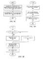
- FIG. 7Aa flowchart depicts a portion of an initialization process in which a network management system prepares for adaptive discovery and adaptive polling in accordance with a preferred embodiment of the present invention.
- the processbegins with the assumption that a network administrator has already performed configuration processes on the network such that configuration information is properly stored where necessary.
- the discovery engineperforms a discovery process to identify IP objects and stored those in the IPOP persistent storage (step 702 ).
- the DSC creator in the DSC managergenerates “initial” DSC objects and stores these within the DSC database (step 704 ).
- a source userthen performs a login on a source endpoint (step 706 ).
- An applicationmay use a resource, termed a target resource, located somewhere within the distributed system, as described above. Hence, the endpoint on which the target resource is located is termed the “target endpoint”.
- the endpoint on which the application is executingis termed the “source endpoint” to distinguish it from the “target endpoint”, and the user of the application is termed the “source user”.
- the security subsystemupdates the active user database for the ORB on which the application is executing (step 708 ).
- the initialization processis then complete.
- FIG. 7Ba flowchart depicts further detail of the initialization process in which the DSC objects are initially created and stored.
- FIG. 7Bprovides more detail for step 704 shown in FIG. 7A .
- each DSC objectprovides guidance on a one-to-one authorization mapping between two points in which a first point (source point) can be a user or an endpoint and a second point (target point) is an endpoint.
- FIG. 7Bdepicts the manner in which the DSC manager initially creates and stores the DSC objects for subsequent use.
- a user associated with an application executing on a source endpointmay request some type of network management action at a target endpoint, or a network management application may automatically perform an action at a target endpoint on behalf of a user that has logged into a source endpoint.
- the systemPrior to completing the necessary network management task, the system must check whether the source user has the proper authorization to perform the task at the target endpoint.
- Some network management applicationswill perform tasks automatically without a user being logged onto the system and using the network management application.
- an application executing on a source endpointmay automatically attempt to perform an action at a target endpoint.
- the systemPrior to completing the necessary network management task, the system must check whether the source endpoint has the proper authorization to perform the task at the target endpoint in a manner similar to the case of the source user performing an action at a target endpoint.
- the previously created and stored DSC objectscan be used to assist in the authorization process.
- the design of the systemhas required a tradeoff between time and effort invested during certain system configuration processes and time and effort invested during certain runtime processes.
- a configuration processmay require more time to complete while the DSC objects are created, but runtime authorization processes become much more efficient.
- the DSC objectsare created and stored within a distributed database during certain configuration processes throughout the system.
- a new systemusually undergoes a significant installation and configuration process.
- endpointsmay be added or deleted, and each addition or deletion generally requires some type of configuration process.
- the DSC objectscan be created or deleted as needed on an ongoing basis.
- the present inventionalso provides an additional advantage by storing the DSC objects within a highly distributed database. Because the present invention provides a network management system for an application framework over a highly distributed data processing system, the system avoids centralized bottlenecks that could occur if the authorization processes had to rely upon a centralized security database or application.
- the first DSC fetchrequires relatively more time than might be required with a centralized subsystem. However, once fetched, a DSC is cached until listeners on the configuration data signal that a change has occurred, at which point the DSC cache must be flushed.
- the process in FIG. 7Bbegins with the DSC manager fetching endpoint data from the IPOP database (step 710 ).
- the IPOP databasewas already populated with IP objects during the discovery process, as mentioned in step 702 of FIG. 7A .
- the DSC managerfetches user data from the all-user database in the security subsystem (step 712 ).
- Configuration datais also fetched from the Configuration Service database or databases (step 714 ), such as ORB IDs that are subsequently used to fetch the ORB address.
- a network administration applicationwill also use the configuration service to store information defined by the administrator.
- the DSC managerthen creates DSC objects for each user/endpoint combination (step 716 ) and for each endpoint/endpoint combination (step 718 ), and the DSC object creation process is then complete.
- FIG. 7Ca flowchart depicts further detail of the initial DSC object creation process in which DSC objects are created and stored for an endpoint/user combination.
- FIG. 7Cprovides more detail for step 716 in FIG. 7B .
- the process shown in FIG. 7Cis a loop through all users that can be identified within the all-user database. In other words, a set of user accounts or identities have already been created and stored over time. However, all users that have been authorized to use the system do not have the same authorized privileges.
- the process shown in FIG. 7 Cis one of the first steps towards storing information that will allow the system to differentiate between users so that it can adaptively monitor the system based partially on the identity of the user for which the system is performing a monitoring task.
- the process in FIG. 7Cbegins by reading scope data for a target endpoint from the IPOP database (step 720 ).
- the DSC creator within the DSC managerthen reads scope data for a source user from the IPOP database (step 722 ).
- a determinationis then made as to whether or not the source user is allowed to access the target endpoint (step 724 ). This determination can be made in the following manner.
- the source user informationis used to make an authorization call to the security subsystem as to whether or not the source user has access to the security group defined in the DSC. It may be assumed that the security system can perform this function efficiently, although the present invention does not depend on auto-generation of security names or security trees.
- the present systemadapts the polling engine per the user/endpoint combination. The present invention should not be understood as depending upon any particular implementation of security authorization.
- the processbranches to check whether another user identity should be processed. If the source user is allowed to access the target endpoint, then a DSC object is created for the current source user and current target endpoint that are being processed (step 726 ). The DSC object is then stored within the DSC database (step 728 ), and a check is made as to whether or not another source user identity requires processing (step 729 ). If so, then the process loops back to get and process another user, otherwise the process is complete.
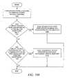
- FIG. 7Da flowchart depicts further detail of the initial DSC object creation process in which DSC objects are created and stored for an endpoint/endpoint combination.
- FIG. 7Dprovides more detail for step 718 in FIG. 7B .
- the process shown in FIG. 7Dis a loop through all endpoints that can be identified within the IPOP database; the IPOP database was already populated with IP objects during the discovery process, as mentioned in step 702 of FIG. 7A .
- an application executing on a source endpointmay attempt to perform an action at a target endpoint. However, not all endpoints within the system have access to requesting actions at all other endpoints within the system.
- the network management systemneeds to attempt to determine whether or not a source endpoint is authorized to request an action from a target endpoint.
- the process shown in FIG. 7Dis one of the first steps towards storing information that will allow the system to differentiate between endpoints so that it can adaptively monitor the system based partially on the identity of the source endpoint for which the system is performing a monitoring task.
- the process in FIG. 7Dbegins by reading scope data for a target endpoint from the IPOP database (step 730 ).
- the DSC creator within the DSC managerthen reads scope data for a source endpoint from the IPOP database (step 732 ).
- a determinationis then made as to whether or not the source endpoint is allowed to access the target endpoint (step 734 ) based on the scope defined in the DSC. For example, a simple scope of X.Y.Z.* will allow an address of X.Y.Z.Q access. If not, then the process branches to check whether another source endpoint should be processed. If the source endpoint is allowed to access the target endpoint, then a DSC object is created for the source endpoint and target endpoint that are currently being processed (step 736 ).
- the DSC objectis then stored within the DSC database (step 738 ), and a check is made as to whether or not another source endpoint requires processing (step 739 ). If so, then the process loops back to get and process another endpoint, otherwise the process is complete.
- the present inventionis applicable to variety of uses, and the previous figures described a general manner in which a device scope context can be associated with a source user or a source endpoint.
- the following figuresdescribe a particular use of the present invention in which DSCs are used to perform polling tasks associated with determining whether or not systems are up or down.
- FIG. 8Aa figure depicts a graphical user interface window that may be used by a network or system administrator to set monitoring parameters for adaptive monitoring associated with users and endpoints in accordance with a preferred embodiment of the present invention.
- Window 800shows a dialog box that is associated with a network management application.
- Input area 802allows a system or network administrator to set polling intervals and to specify whether the polling intervals are to be associated with a user or with an endpoint.
- Input field 804allows the user to input a numerical value for the polling interval, which is the length of time between polls of an endpoint.
- Radio button 805allows an administrator to associate the polling interval with a specific user as specified by drop-down menu 806 .
- Radio button 807allows an administrator to associate the polling interval with a specific endpoint as specified by drop-down menu 808 .
- Input area 810allows a system or network administrator to specify whether the user or the endpoint is to be used as a primary DSC.
- DSC objectsare created for both a user/endpoint combination and an endpoint/endpoint combination.
- Radio buttons 812 - 814allow the user to select whether the polling time intervals of associated with the user or associated with the endpoint are to be regarded as primary or controlling. If a user is logged onto to an ORB associated with an endpoint, such that it might be possible that the polling engine should poll on an interval associated with the network administrator, the selection of the primary DSC will determine whether the DSC should use the polling interval values associated with the user or the endpoint if available. Buttons 816 and 818 allow the user to set the values as necessary.
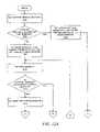
- a flowchartshows a process by which the polling time parameters are set in the appropriate DSC objects after polling time parameters have been specified by an administrator.
- the processbegins when the administrative application receives a request to set a polling interval (step 822 ), e.g., when a user enters a polling interval value in window 800 in FIG. 8A .
- a determinationis then made as to whether or not the polling interval is to be associated with a source user (step 824 ). If so, the DSC manager fetches a DSC for a specified user/endpoint combination (step 826 ), and the new polling interval is added as a property to the DSC (step 828 ).
- step 824determines whether there are other target endpoints with which the polling interval should be associated (step 830 ). If so, then the process loops back to step 826 to process another user/endpoint combination. If not, then the process is complete for all user/endpoint combinations.
- step 832If it is determined that the polling interval is to be associated with a source endpoint (step 832 ), then the DSC manager fetches a DSC for a specified endpoint/endpoint combination (step 834 ), and the new polling interval is added as a property to the DSC (step 836 ). The process then determines whether there are other target endpoints with which the polling interval should be associated (step 838 ). If so, then the process loops back to step 834 to process another endpoint/endpoint combination. If not, then the process is complete for all endpoint/endpoint combinations.
- step 840the system can log or report an error (step 840 ), and the process is complete.
- a flowchartshows a process by which a polling time property is added to a DSC after polling time parameters have been specified by an administrator.
- the DSC managergets a property vector from the DKS configuration service which has stored the values entered by the administrator in window 800 of FIG. 8A (step 850 ) and sets the user-specified polling interval in the property vector (step 852 ).
- the DSC manager and an administration applicationsuch as that shown as window 800 in FIG. 8A , communicate via properties stored by the configuration service.
- the DSC manageris then instructed to add rows to the DSC database for the new property (step 854 ).
- the new propertyis advertised to “consumers” or users of the property, as needed (step 856 ), and the process is complete.
- a flowchartshows a process for advertising newly specified polling time properties after polling time parameters have been specified by an administrator.
- the processbegins with the DSC manager determining the DSC component or DSC consumer of the newly specified property (step 860 ). The DSC consumer is then notified of the updated property (step 862 ), and the process is complete.
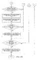
- a flowchartshows a process used by a polling engine to monitor systems within a network after polling time parameters have been specified by an administrator.
- the processbegins with the system determining the appropriate network for which the polling engine is responsible for monitoring (step 902 ). After the network is determined, then all of the systems within the network are identified (step 904 ), and all of the endpoints within those systems are identified (step 906 ). All of these data items are cached, as the polling engine will attempt to poll each of the endpoints on the appropriate intervals.
- the polling engineselects a target endpoint (step 908 ) to be polled.
- a DSC object for the source endpoint for the polling requestis obtained (step 912 ), and a DSC object for the user logged on to the source endpoint is also obtained (step 912 ).
- the polling enginerequests the DSC manager for a DSC to be used during the polling operation (step 914 ).
- the polling enginethen begins polling the target endpoint on the proper interval (step 916 ), and the process is complete.
- the polling processmay be continuous; for example, the administrator has requested that the administration application continually monitor the status of a certain set of devices. In other cases, the administrator may be performing “demand polling” on a more limited basis at the specific request of an administrator. Hence, the process shown in FIG. 9A may be part of a continuous loop through polling tasks.
- FIG. 9Ba flowchart shows a process used by a polling engine to get a DSC for a user/endpoint combination.
- FIG. 9Bprovides more detail for step 910 in FIG. 9A .
- the processbegins when the polling engine asks the ORB for a host name (step 922 ), and then the polling engine asks a domain name server for an address associated with the host name (step 924 ).
- the IPOP Serviceis requested to construct an endpoint from the address from the domain name server (step 926 ), and the DSC manager is requested to construct a DSC object from the source endpoint and the target endpoint (step 928 ).
- the process of obtaining this DSCis then complete.
- FIG. 9Ca flowchart shows a process used by a polling engine to get a DSC for an endpoint/endpoint combination.
- FIG. 9Cprovides more detail for step 912 in FIG. 9A .
- the processbegins when the polling engine asks the security authentication subsystem for the source user that is logged onto the same ORB on which the polling engine resides (step 932 ).
- the DSC manageris requested to construct a DSC object for the source user and the target endpoint (step 934 ).
- the process of obtaining this DSCis then complete.
- FIG. 9Da flowchart shows a process used by a polling engine to get a DSC from the DSC manager.
- FIG. 9Cprovides more detail for step 914 in FIG. 9A .
- the processbegins when the polling engine sends both newly constructed DSCs to the DSC manager (step 942 ), and the DSC manager searches for a DSC within the DSC database that matches one of the two newly constructed DSCs (step 944 ). While it is possible to have two matches, i.e. a user/endpoint match and an endpoint/endpoint match, the selection of a primary DSC, or similarly, the system enforcement of a default primary DSC, avoid collisions. The DSC manager then returns a matching DSC to the polling engine, if available, and the process is complete.
- FIG. 9Ea flowchart shows a process used by a polling engine to queue a polling task.
- the process shown in FIG. 9E and FIG. 9Fprovides more detail for step 916 shown in FIG. 9A .
- the processbegins when a check is made as to whether a matching DSC is available (step 950 ). If so, then the polling time interval is obtained from the DSC (step 952 ). If not, then the polling time interval is set to a default value for this or all endpoints (step 954 ). In either case, the polling engine stores the polling time interval in its cache for the endpoint (step 956 ). A task data structure for the poll action on the target endpoint is then queued (step 958 ), and the process is complete.
- a flowchartshows a process used by a polling engine to perform a polling task on an endpoint.
- the process shown in FIG. 9E and FIG. 9Fprovides more detail for step 916 shown in FIG. 9A .
- the processbegins by retrieving the next poll task from a task queue (step 960 ).
- the polling engine's main functionis to poll systems within the highly distributed network
- the polling enginemay have a component whose sole purpose is to manage the task queue as a large event loop.
- a set of execution threads within a thread poolcan be used as a set of resources; each polling task can be placed on a separate thread. The threads can then be blocked, put to sleep, etc., while the thread awaits the completion of its task.
- the time of the last poll of the target endpointis then retrieved (step 962 ).
- the last poll timeis then compared with the polling interval for the target endpoint, and a check is made as to whether or not enough time has passed since the last poll in accordance with the specified polling interval (step 964 ). If so, then a ping is sent to the target endpoint (step 966 ).
- the polling engineasks the DSC manager for a DSC by giving the DSC manager the source endpoint and the target endpoint. The DSC manager then looks for matches with the user/target endpoint DSC and the source endpoint/target endpoint DSC in the DSC database. If no DSC exists, then the default DSC is returned to the polling engine. If two DSCs exist, then the DSC manager will determine whether to use the user/endpoint or endpoint/endpoint DSC based on the primary DSC defined by the administrator, as explained above. If the polling engine receives no DSC, then the action is not authorized and the polling engine does not unnecessarily ask the gateway for an application action object.
- the polling enginereceives no DSC, then the action is not authorized and the polling engine does not unnecessarily ask the gateway for an application action object.
- the thread that is being used for the polling taskawakes (step 968 ), and a determination is made as to whether or not a good ping response has been received for the previous ping for this task (step 970 ). If so, then the polling engine can report or log that the target endpoint is operational, i.e. up (step 972 ), and the process for this poll task is complete.
- step 974a determination is made as to whether or not the ping has timed out. If so, then the polling engine can report or log that the target endpoint is not operational, i.e. down (step 976 ), and the process for this poll task is complete.
- step 974the thread again waits for the response at step 968 . If appropriate polling interval for this endpoint has not yet passed, then the endpoint should not yet be polled again, and the process branches to exit the thread (step 978 ) and process another task in the task queue.
- FIGS. 9A-9Fillustrate one particular management activity that may occur on a highly distributed data processing system, yet other management activities are possible.
- management activitieswhen management activities are performed at a particular machine, a significant amount of bandwidth may be consumed.
- a service providerattempts to minimize the reduction of bandwidth that is caused by any system management activities while also attempting to increase the reliability of the system through fault-tolerant solutions.
- One manner of increasing reliability yet also maintaining performance of the distributed systemwould include providing plentiful IP addresses, which can be accomplished in several different ways, and installing a second NIC in some machines within the distributed system, which is a viable option as the cost of NICs decreases.
- the extra NIC in a given machinemay be termed a “twin NIC”.
- Any given NICmay then be categorized as being represented by a mission critical endpoint or a non-mission critical endpoint as determined by an administrator.
- the systemmay then perform management activities, such as polling, without regard to the manner in which a given endpoint has been categorized.
- management activitiessuch as polling
- FIGS. 10A-10Bdepict processes that may be combined with the processes described above with respect to FIGS. 7A-7D
- FIG. 10Cdepicts a process that may be combined with the polling process shown in FIG. 9F
- FIGS. 10D-10Edepict examples of processes that may be used to reroute the execution of action objects in a system that implements twin endpoints.
- a flowchartdepicts a process by which an administrator may configure a machine with a twin NIC through a combination of manual and programmatic steps.
- the processbegins with the administrator identifying mission critical endpoints (step 1002 ) and identifying non-mission critical actions that may be performed (step 1004 ).
- the administratormay then place extra, or “twin”, NICs into mission critical systems (step 1006 ).
- the placement of additional NICsis a manual process, and the steps of identifying and categorizing endpoints and actions are potentially a combination of manual steps and software-assisted user selectable actions within a network/system management application.
- the administratorthen configures the IP addresses of the additional NICs via the appropriate network management applications (step 1008 ), and the administrator may optionally configure hostnames and domain name servers for the modified systems (step 1010 ).
- the administratorthen associates the newly added twin NICs with their corresponding mission critical NICs via the appropriate network management applications (step 1012 ), and the configuration process is complete.
- FIG. 10Ba flowchart depicts a process by which a discovery process may be adjusted to detect twin NICs.
- the process shown in FIG. 10Bmay occur during the discovery process depicted as step 702 in FIG. 7A .
- This portion of the discovery processbegins when the IP driver subsystem discovers a system with multiple NICs (step 1020 ). A determination is then made as to whether one of the NICs has been designated as a twin NIC that is to be used for monitoring purposes only (step 1022 ). If so, then the process branches so that the designation is saved within the IPOP database as a twin mission critical endpoint (step 1024 ), and the process is complete.
- FIG. 10Ca flowchart depicts a process by which a polling process may be adjusted when certain endpoints have been categorized as mission critical endpoints.
- a polling enginesends a “Ping” action to an endpoint, and the polling engine then receives the status returned by the requested action, after which the status of the endpoint is updated.
- the process shown within FIG. 10Cmay be combined with the polling process shown in FIG. 9F .
- the process shown in FIG. 10Chas a preliminary portion in which it is determined whether the endpoint that is to be polled has been given a special designation, a portion during which a polling action is performed, and a concluding portion in which the status of the endpoint is updated.
- the process shown in FIG. 10Ccould be combined with the process shown in FIG. 9F by performing the appropriate pre-polling steps prior to performing the polling action and then also performing the appropriate post-polling steps after performing the polling action.
- the process shown in FIG. 10Cassumes that the target endpoint is a mission critical endpoint.
- the processbegins with a determination as to whether the target endpoint is a mission critical endpoint and whether a twin endpoint exists for the target endpoint (step 1030 ). If both conditions are not true, then the polling engine polls the mission critical endpoint (step 1032 ) and updates the status of the mission critical endpoint (step 1034 ), and the process is complete. In that case, the mission critical endpoint has not been configured with a twin endpoint through which monitoring operations may be performed; hence, the bandwidth on the mission critical endpoint has not been reserved solely for mission critical actions, and the monitoring operation performed by the polling engine necessarily consumes some of the bandwidth from the mission critical endpoint.
- the polling engineperforms the polling action on the twin endpoint (step 1036 ) and updates the status of the twin endpoint when received (step 1038 ).
- a determinationis then made as to whether or not the mission critical endpoint can be polled (step 1040 ). If so, then the polling engine also polls the mission critical endpoint (step 1042 ), and the endpoint status of the mission critical endpoint is updated when the status is received (step 1044 ).
- the polling operation on the twin endpoint and the mission critical endpointmay be performing in parallel by executing the operation on separate threads.
- the mission critical endpointhas been configured with a twin endpoint through which monitoring operations may be performed, thereby preserving the bandwidth on the mission critical endpoint for mission critical actions, and the monitoring operation performed by the polling engine attempts to automatically limit the bandwidth consumed from the mission critical endpoint for monitoring operations.
- FIG. 10Da flowchart depicts a process by which an application may request an action on a DKS endpoint without regard to whether or not the application is aware of the fact that the endpoint has been categorized as a mission critical endpoint.
- the system management frameworkmay reroute the action object to a non-mission critical endpoint, and the application that has requested the action should be able to continue processing without regard to the rerouting unless it is necessary for the application to do so.
- the processbegins when an application requests that a gateway perform an action on a DKS endpoint that is not mission critical (step 1050 ).
- the DKS endpoint gatewayreceives an IPOPOid from the application (step 1052 ), and the gateway asks IPOP to decode the address in the request (step 1054 ).
- DKS IPOPreceives the IPOPOid and performs a search in the IPOP database to find the endpoint (step 1056 ).
- IPOPthen returns a fetched endpoint within an APPLICATION_ACTION_OBJECT, described in more detail further below with respect to FIG. 11B , to the gateway that passes it back to the application (step 1058 ).
- the applicationcan then perform the action within the returned object (step 1060 ), and the process is then complete.
- the applicationcan perform an action, which may be rerouted, and the application does not necessarily have to be concerned with the fact that the action has been rerouted.
- FIG. 10Ea flowchart depicts a process by which the IPOP database performs a search to find an appropriate endpoint against which a requested action should be executed with consideration of whether the endpoint is a mission critical endpoint.
- FIG. 10Eshows more detail for step 1056 in FIG. 10D .
- the process shown in FIG. 10Eshows a series of steps in which the system determines whether to use an endpoint corresponding to the IPOPOid that was originally specified by an application or whether the system should use a different endpoint based on the categorization of the endpoints, and the different endpoint would necessarily have a different IPOPOid.
- the processbegins when IPOP attempts to match the IPOPOid in the request from the gateway with an endpoint stored in the IPOP database (step 1064 ). If IPOP has found an endpoint with a matching IPOPOid, then a determination is made as to whether the matched endpoint is a mission critical endpoint and whether a twin exists for the mission critical endpoint (step 1066 ). If so, then the IPOPOid of the twin endpoint is used to fetch the endpoint object from the IPOP database (step 1068 ), and an indication is set in the returned endpoint object that a twin endpoint was used to reroute the action (step 1070 ), and the process is complete.
- the endpoint corresponding to the matched IPOPOid from the original requestis then used (step 1072 ), and the process is complete. If neither condition holds but a matching IPOPOid is found, then the corresponding endpoint is fetched from the IPOP database (step 1074 ), and the process is complete.
- FIG. 10Fa figure depicts a graphical user interface window that may be used by a network or system administrator to set assign an endpoint to be used as a mission critical twin endpoint for a mission critical endpoint in accordance with a preferred embodiment of the present invention.
- Window 1090is a dialog box or an equivalent user interface item within a network management application that allows an administrator to set a mission critical twin endpoint.
- the administratorhas already chosen the mission critical endpoint for which an assignment will be made; text field 1091 contains the address of the mission critical endpoint.
- Check boxes 1092allow the administrator to choose the manner in which the twin endpoint will be specified.
- Entry field 1093may be used to enter the MAC address of the twin endpoint.
- Entry fields 1094 and 1095may be used to enter a network address comprising a virtual private network number and an IP address, respectively.
- “Set” button 1096assigns the twin endpoint
- “Clear” button 1097clears the dialog box, or alternatively, clears the previous twin endpoint assignment for the mission critical endpoint.
- FIGS. 11A-11Esome simplified pseudo-code depicts the manner in which endpoint objects and action objects can be implemented in an object-oriented manner.
- FIG. 11Adepicts a class for implementing action objects
- FIG. 11Bdepicts a manner in which an action object class can be extended to include mission critical categories.
- FIG. 11Cdepicts a class for implementing endpoints
- FIG. 11D and FIG. 11Edepicts class for extending an endpoint class to include mission critical categories.
- the present inventiontakes advantage of the flexible polling and monitoring scheme associated with the DKS system by providing automatic associations between mission critical and non-mission critical endpoints.
- a backup status gathering machinemay be automatically determined from the manner in which the machines have communicated rather that a static association assigned by an administrator, as explained below.
- a set of flowchartsdepicts a process by which a mission-critical-twin endpoint can be located for a mission critical endpoint in accordance with a preferred embodiment of the present invention.
- the processbegins by obtaining or receiving a mission critical endpoint (step 1202 ) and then determining whether or not a twin endpoint has been designated for the mission critical endpoint (step 1204 ). If a twin endpoint has been designated for the mission critical endpoint, then a mission-critical-twin endpoint is already identifiable. Hence, the twin for the mission critical endpoint is set equal to the twin that has been designated by the administrator (step 1206 ).
- an arrayis filled or initialized with all possible endpoints that are not already twin endpoints (step 1208 ).
- a next endpointis then retrieved from the array (step 1210 ), and this endpoint is used as an endpoint that is currently being processed in the remaining steps.
- the following steps in FIGS. 12A-12Bare an execution loop for processing the remaining endpoints within the array.
- step 1212The process continues with a determination of whether or not the current endpoint is a non-mission critical endpoint (step 1212 ). If not, then the endpoint is a mission critical endpoint, which should not be used as a twin endpoint, and the process branches to step 1226 to process another endpoint from the array.
- the endpointis a non-mission critical endpoint
- the SNMP tableis retrieved from the endpoint (step 1214 ).
- a determinationis made as to whether the current endpoint has communicated with the mission critical endpoint (step 1216 ), which can be done by searching the current endpoint's SNMP table for an address that corresponds to the address for the mission critical endpoint.
- Alternative mechanismscould be employed to determine a communication link between the current endpoint and the mission critical endpoint. If the current endpoint has not communicated with the mission critical endpoint, then it has not been affiliated or associated with the mission critical endpoint, and the current endpoint should not be used as a twin for the mission critical endpoint. Hence, the process branches to step 1226 to process another endpoint from the array.
- the current endpointIf the current endpoint has communicated with the mission critical endpoint, then it is added to a storage vector of twin endpoint candidates (step 1218 ), i.e. some type of data structure for temporarily storing the endpoints other than the previously mentioned array.
- the number of times that the endpoint has communicated with the mission critical endpointcan also be stored in the storage vector as a subsequent comparison value, if available (step 1220 ). Otherwise, a default, configuration value that has been previously associated with the current endpoint may be stored with the current endpoint in the storage vector as a subsequent comparison value after retrieving the default value from the configuration service.
- the present inventionprovides a flexible polling and monitoring scheme associated with network management tasks in a highly distributed system. Backup monitoring of endpoints can be accomplished through the use of system level information.
- a non-mission-critical endpointis associated with a mission-critical endpoint based on the non-mission-critical endpoint's communication history with the mission critical endpoint.
- the management systemmay use the status of a non-mission-critical endpoint as a reflection of the status of a mission-critical endpoint.
Landscapes
- Engineering & Computer Science (AREA)
- Computer Networks & Wireless Communication (AREA)
- Signal Processing (AREA)
- Environmental & Geological Engineering (AREA)
- Computer And Data Communications (AREA)
- Data Exchanges In Wide-Area Networks (AREA)
Abstract
Description
| Subnet address | Subnet mask | ||
| 147.0.0.0 | 255.255.0.0 | ||
| 147.1.0.0 | 255.255.0.0 | ||
| 146.100.0.0 | 255.255.0.0 | ||
| 69.0.0.0 | 255.0.0.0 | ||
- IP network—privateNetworkID/binaryNetworkAddress
- IP system—privateNetworkID/binaryIPAddress/system
- IP endpoint—privateNetworkID/binaryNetworkAddress/endppoint
For example:
A network “146.84.28.0:255.255.255.0” in privateNetworkID 12 has unique name: - 12/1/0/0/1/0/0/1/0/0/1/0/1/0/1/0/0/0/0/1/1/1/0/0.
A system “146.84.28.22” in privateNetworkID 12 has unique name: - 12/1/0/0/1/0/0/1/0/0/1/0/1/0/1/0/0/0/0/0/1/1/1/0/0/0/0/0/1/0/1/1/0/system.
- An endpoint “146.84.28.22” in privateNetworkId 12 has unique name:
- 12/1/0/0/1/0/0/1/0/0/1/0/1/0/1/0/0/0/0/0/1/1/1/0/0/0/0/0/1/0/1/1/0/endpoint.
Claims (12)
Priority Applications (1)
| Application Number | Priority Date | Filing Date | Title |
|---|---|---|---|
| US09/737,434US7305461B2 (en) | 2000-12-15 | 2000-12-15 | Method and system for network management with backup status gathering |
Applications Claiming Priority (1)
| Application Number | Priority Date | Filing Date | Title |
|---|---|---|---|
| US09/737,434US7305461B2 (en) | 2000-12-15 | 2000-12-15 | Method and system for network management with backup status gathering |
Publications (2)
| Publication Number | Publication Date |
|---|---|
| US20020112039A1 US20020112039A1 (en) | 2002-08-15 |
| US7305461B2true US7305461B2 (en) | 2007-12-04 |
Family
ID=24963909
Family Applications (1)
| Application Number | Title | Priority Date | Filing Date |
|---|---|---|---|
| US09/737,434Expired - Fee RelatedUS7305461B2 (en) | 2000-12-15 | 2000-12-15 | Method and system for network management with backup status gathering |
Country Status (1)
| Country | Link |
|---|---|
| US (1) | US7305461B2 (en) |
Cited By (108)
| Publication number | Priority date | Publication date | Assignee | Title |
|---|---|---|---|---|
| US20050271047A1 (en)* | 2004-06-02 | 2005-12-08 | Huonder Russell J | Method and system for managing multiple overlapping address domains |
| US20060126534A1 (en)* | 2004-12-10 | 2006-06-15 | Huibregtse Thomas P | Method and mechanism for identifying an unmanaged switch in a network |
| US20070042780A1 (en)* | 2005-08-16 | 2007-02-22 | Qualcomm Incorporated | Methods and systems for adaptive server selection in wireless communications |
| US20080114781A1 (en)* | 2006-11-12 | 2008-05-15 | Dell Products L.P. | Methods to Model NIC Teaming and Load Balancing |
| US20100077409A1 (en)* | 2008-09-25 | 2010-03-25 | Dell Products L.P. | System integrated teaming |
| US8335842B2 (en) | 2004-03-16 | 2012-12-18 | Icontrol Networks, Inc. | Premises management networking |
| US8363604B2 (en) | 2005-02-01 | 2013-01-29 | Qualcomm Incorporated | Method and apparatus for controlling a transmission data rate based on feedback relating to channel conditions |
| US8473619B2 (en) | 2005-03-16 | 2013-06-25 | Icontrol Networks, Inc. | Security network integrated with premise security system |
| US8612591B2 (en) | 2005-03-16 | 2013-12-17 | Icontrol Networks, Inc. | Security system with networked touchscreen |
| US8713132B2 (en) | 2005-03-16 | 2014-04-29 | Icontrol Networks, Inc. | Device for data routing in networks |
| US8819178B2 (en) | 2005-03-16 | 2014-08-26 | Icontrol Networks, Inc. | Controlling data routing in integrated security systems |
| US8825871B2 (en) | 2005-03-16 | 2014-09-02 | Icontrol Networks, Inc. | Controlling data routing among networks |
| US8988221B2 (en) | 2005-03-16 | 2015-03-24 | Icontrol Networks, Inc. | Integrated security system with parallel processing architecture |
| US8996665B2 (en) | 2005-03-16 | 2015-03-31 | Icontrol Networks, Inc. | Takeover processes in security network integrated with premise security system |
| US9059863B2 (en) | 2005-03-16 | 2015-06-16 | Icontrol Networks, Inc. | Method for data routing in networks |
| US9144143B2 (en) | 2010-04-30 | 2015-09-22 | Icontrol Networks, Inc. | Power and data solution for remote low-power devices |
| US9172553B2 (en) | 2005-03-16 | 2015-10-27 | Icontrol Networks, Inc. | Security system with networked touchscreen and gateway |
| US9191228B2 (en) | 2005-03-16 | 2015-11-17 | Icontrol Networks, Inc. | Cross-client sensor user interface in an integrated security network |
| US9287727B1 (en) | 2013-03-15 | 2016-03-15 | Icontrol Networks, Inc. | Temporal voltage adaptive lithium battery charger |
| US9306809B2 (en) | 2007-06-12 | 2016-04-05 | Icontrol Networks, Inc. | Security system with networked touchscreen |
| US9349276B2 (en) | 2010-09-28 | 2016-05-24 | Icontrol Networks, Inc. | Automated reporting of account and sensor information |
| US9412248B1 (en) | 2007-02-28 | 2016-08-09 | Icontrol Networks, Inc. | Security, monitoring and automation controller access and use of legacy security control panel information |
| US9450776B2 (en) | 2005-03-16 | 2016-09-20 | Icontrol Networks, Inc. | Forming a security network including integrated security system components |
| US20160274759A1 (en) | 2008-08-25 | 2016-09-22 | Paul J. Dawes | Security system with networked touchscreen and gateway |
| US9510065B2 (en) | 2007-04-23 | 2016-11-29 | Icontrol Networks, Inc. | Method and system for automatically providing alternate network access for telecommunications |
| US9531593B2 (en) | 2007-06-12 | 2016-12-27 | Icontrol Networks, Inc. | Takeover processes in security network integrated with premise security system |
| US9609003B1 (en) | 2007-06-12 | 2017-03-28 | Icontrol Networks, Inc. | Generating risk profile using data of home monitoring and security system |
| US9621408B2 (en) | 2006-06-12 | 2017-04-11 | Icontrol Networks, Inc. | Gateway registry methods and systems |
| US9628440B2 (en) | 2008-11-12 | 2017-04-18 | Icontrol Networks, Inc. | Takeover processes in security network integrated with premise security system |
| US9729342B2 (en) | 2010-12-20 | 2017-08-08 | Icontrol Networks, Inc. | Defining and implementing sensor triggered response rules |
| US9867143B1 (en) | 2013-03-15 | 2018-01-09 | Icontrol Networks, Inc. | Adaptive Power Modulation |
| US9928975B1 (en) | 2013-03-14 | 2018-03-27 | Icontrol Networks, Inc. | Three-way switch |
| US10051078B2 (en) | 2007-06-12 | 2018-08-14 | Icontrol Networks, Inc. | WiFi-to-serial encapsulation in systems |
| US10062273B2 (en) | 2010-09-28 | 2018-08-28 | Icontrol Networks, Inc. | Integrated security system with parallel processing architecture |
| US10079839B1 (en) | 2007-06-12 | 2018-09-18 | Icontrol Networks, Inc. | Activation of gateway device |
| US10078958B2 (en) | 2010-12-17 | 2018-09-18 | Icontrol Networks, Inc. | Method and system for logging security event data |
| US10091014B2 (en) | 2005-03-16 | 2018-10-02 | Icontrol Networks, Inc. | Integrated security network with security alarm signaling system |
| US10142392B2 (en) | 2007-01-24 | 2018-11-27 | Icontrol Networks, Inc. | Methods and systems for improved system performance |
| US10156959B2 (en) | 2005-03-16 | 2018-12-18 | Icontrol Networks, Inc. | Cross-client sensor user interface in an integrated security network |
| US10200504B2 (en) | 2007-06-12 | 2019-02-05 | Icontrol Networks, Inc. | Communication protocols over internet protocol (IP) networks |
| US10237237B2 (en) | 2007-06-12 | 2019-03-19 | Icontrol Networks, Inc. | Communication protocols in integrated systems |
| US10313303B2 (en) | 2007-06-12 | 2019-06-04 | Icontrol Networks, Inc. | Forming a security network including integrated security system components and network devices |
| US10339791B2 (en) | 2007-06-12 | 2019-07-02 | Icontrol Networks, Inc. | Security network integrated with premise security system |
| US10348575B2 (en) | 2013-06-27 | 2019-07-09 | Icontrol Networks, Inc. | Control system user interface |
| US10365810B2 (en) | 2007-06-12 | 2019-07-30 | Icontrol Networks, Inc. | Control system user interface |
| US10380871B2 (en) | 2005-03-16 | 2019-08-13 | Icontrol Networks, Inc. | Control system user interface |
| US10382452B1 (en) | 2007-06-12 | 2019-08-13 | Icontrol Networks, Inc. | Communication protocols in integrated systems |
| US10389736B2 (en) | 2007-06-12 | 2019-08-20 | Icontrol Networks, Inc. | Communication protocols in integrated systems |
| US10423309B2 (en) | 2007-06-12 | 2019-09-24 | Icontrol Networks, Inc. | Device integration framework |
| US10498830B2 (en) | 2007-06-12 | 2019-12-03 | Icontrol Networks, Inc. | Wi-Fi-to-serial encapsulation in systems |
| US10522026B2 (en) | 2008-08-11 | 2019-12-31 | Icontrol Networks, Inc. | Automation system user interface with three-dimensional display |
| US10523689B2 (en) | 2007-06-12 | 2019-12-31 | Icontrol Networks, Inc. | Communication protocols over internet protocol (IP) networks |
| US10530839B2 (en) | 2008-08-11 | 2020-01-07 | Icontrol Networks, Inc. | Integrated cloud system with lightweight gateway for premises automation |
| US10559193B2 (en) | 2002-02-01 | 2020-02-11 | Comcast Cable Communications, Llc | Premises management systems |
| US10616075B2 (en) | 2007-06-12 | 2020-04-07 | Icontrol Networks, Inc. | Communication protocols in integrated systems |
| US10645347B2 (en) | 2013-08-09 | 2020-05-05 | Icn Acquisition, Llc | System, method and apparatus for remote monitoring |
| US10666523B2 (en) | 2007-06-12 | 2020-05-26 | Icontrol Networks, Inc. | Communication protocols in integrated systems |
| US10721087B2 (en) | 2005-03-16 | 2020-07-21 | Icontrol Networks, Inc. | Method for networked touchscreen with integrated interfaces |
| US10747216B2 (en) | 2007-02-28 | 2020-08-18 | Icontrol Networks, Inc. | Method and system for communicating with and controlling an alarm system from a remote server |
| US10785319B2 (en) | 2006-06-12 | 2020-09-22 | Icontrol Networks, Inc. | IP device discovery systems and methods |
| US10979389B2 (en) | 2004-03-16 | 2021-04-13 | Icontrol Networks, Inc. | Premises management configuration and control |
| US10986213B2 (en)* | 2019-01-30 | 2021-04-20 | GAVS Technologies Pvt. Ltd. | Method and system for streaming management information base data using simple network management protocol |
| US10999254B2 (en) | 2005-03-16 | 2021-05-04 | Icontrol Networks, Inc. | System for data routing in networks |
| US11089122B2 (en) | 2007-06-12 | 2021-08-10 | Icontrol Networks, Inc. | Controlling data routing among networks |
| US11113950B2 (en) | 2005-03-16 | 2021-09-07 | Icontrol Networks, Inc. | Gateway integrated with premises security system |
| US11146637B2 (en) | 2014-03-03 | 2021-10-12 | Icontrol Networks, Inc. | Media content management |
| US11182060B2 (en) | 2004-03-16 | 2021-11-23 | Icontrol Networks, Inc. | Networked touchscreen with integrated interfaces |
| US11201755B2 (en) | 2004-03-16 | 2021-12-14 | Icontrol Networks, Inc. | Premises system management using status signal |
| US11212192B2 (en) | 2007-06-12 | 2021-12-28 | Icontrol Networks, Inc. | Communication protocols in integrated systems |
| US11218878B2 (en) | 2007-06-12 | 2022-01-04 | Icontrol Networks, Inc. | Communication protocols in integrated systems |
| US11237714B2 (en) | 2007-06-12 | 2022-02-01 | Control Networks, Inc. | Control system user interface |
| US11244545B2 (en) | 2004-03-16 | 2022-02-08 | Icontrol Networks, Inc. | Cross-client sensor user interface in an integrated security network |
| US11258625B2 (en) | 2008-08-11 | 2022-02-22 | Icontrol Networks, Inc. | Mobile premises automation platform |
| US11277465B2 (en) | 2004-03-16 | 2022-03-15 | Icontrol Networks, Inc. | Generating risk profile using data of home monitoring and security system |
| US11310199B2 (en) | 2004-03-16 | 2022-04-19 | Icontrol Networks, Inc. | Premises management configuration and control |
| US11316958B2 (en) | 2008-08-11 | 2022-04-26 | Icontrol Networks, Inc. | Virtual device systems and methods |
| US11316753B2 (en) | 2007-06-12 | 2022-04-26 | Icontrol Networks, Inc. | Communication protocols in integrated systems |
| US11343380B2 (en) | 2004-03-16 | 2022-05-24 | Icontrol Networks, Inc. | Premises system automation |
| US11368327B2 (en) | 2008-08-11 | 2022-06-21 | Icontrol Networks, Inc. | Integrated cloud system for premises automation |
| US11405463B2 (en) | 2014-03-03 | 2022-08-02 | Icontrol Networks, Inc. | Media content management |
| US11424980B2 (en) | 2005-03-16 | 2022-08-23 | Icontrol Networks, Inc. | Forming a security network including integrated security system components |
| US11423756B2 (en) | 2007-06-12 | 2022-08-23 | Icontrol Networks, Inc. | Communication protocols in integrated systems |
| US11451409B2 (en) | 2005-03-16 | 2022-09-20 | Icontrol Networks, Inc. | Security network integrating security system and network devices |
| US11489812B2 (en) | 2004-03-16 | 2022-11-01 | Icontrol Networks, Inc. | Forming a security network including integrated security system components and network devices |
| US11496568B2 (en) | 2005-03-16 | 2022-11-08 | Icontrol Networks, Inc. | Security system with networked touchscreen |
| US11582065B2 (en) | 2007-06-12 | 2023-02-14 | Icontrol Networks, Inc. | Systems and methods for device communication |
| US11601810B2 (en) | 2007-06-12 | 2023-03-07 | Icontrol Networks, Inc. | Communication protocols in integrated systems |
| US11615697B2 (en) | 2005-03-16 | 2023-03-28 | Icontrol Networks, Inc. | Premise management systems and methods |
| US11646907B2 (en) | 2007-06-12 | 2023-05-09 | Icontrol Networks, Inc. | Communication protocols in integrated systems |
| US11677577B2 (en) | 2004-03-16 | 2023-06-13 | Icontrol Networks, Inc. | Premises system management using status signal |
| US11700142B2 (en) | 2005-03-16 | 2023-07-11 | Icontrol Networks, Inc. | Security network integrating security system and network devices |
| US11706045B2 (en) | 2005-03-16 | 2023-07-18 | Icontrol Networks, Inc. | Modular electronic display platform |
| US11706279B2 (en) | 2007-01-24 | 2023-07-18 | Icontrol Networks, Inc. | Methods and systems for data communication |
| US11729255B2 (en) | 2008-08-11 | 2023-08-15 | Icontrol Networks, Inc. | Integrated cloud system with lightweight gateway for premises automation |
| US11750414B2 (en) | 2010-12-16 | 2023-09-05 | Icontrol Networks, Inc. | Bidirectional security sensor communication for a premises security system |
| US11758026B2 (en) | 2008-08-11 | 2023-09-12 | Icontrol Networks, Inc. | Virtual device systems and methods |
| US11792330B2 (en) | 2005-03-16 | 2023-10-17 | Icontrol Networks, Inc. | Communication and automation in a premises management system |
| US11792036B2 (en) | 2008-08-11 | 2023-10-17 | Icontrol Networks, Inc. | Mobile premises automation platform |
| US11811845B2 (en) | 2004-03-16 | 2023-11-07 | Icontrol Networks, Inc. | Communication protocols over internet protocol (IP) networks |
| US11816323B2 (en) | 2008-06-25 | 2023-11-14 | Icontrol Networks, Inc. | Automation system user interface |
| US11831462B2 (en) | 2007-08-24 | 2023-11-28 | Icontrol Networks, Inc. | Controlling data routing in premises management systems |
| US11916928B2 (en) | 2008-01-24 | 2024-02-27 | Icontrol Networks, Inc. | Communication protocols over internet protocol (IP) networks |
| US11916870B2 (en) | 2004-03-16 | 2024-02-27 | Icontrol Networks, Inc. | Gateway registry methods and systems |
| US12003387B2 (en) | 2012-06-27 | 2024-06-04 | Comcast Cable Communications, Llc | Control system user interface |
| US12063220B2 (en) | 2004-03-16 | 2024-08-13 | Icontrol Networks, Inc. | Communication protocols in integrated systems |
| US12063221B2 (en) | 2006-06-12 | 2024-08-13 | Icontrol Networks, Inc. | Activation of gateway device |
| US12184443B2 (en) | 2007-06-12 | 2024-12-31 | Icontrol Networks, Inc. | Controlling data routing among networks |
| US12283172B2 (en) | 2007-06-12 | 2025-04-22 | Icontrol Networks, Inc. | Communication protocols in integrated systems |
Families Citing this family (13)
| Publication number | Priority date | Publication date | Assignee | Title |
|---|---|---|---|---|
| US8176137B2 (en)* | 2001-01-31 | 2012-05-08 | Accenture Global Services Limited | Remotely managing a data processing system via a communications network |
| US7389341B2 (en) | 2001-01-31 | 2008-06-17 | Accenture Llp | Remotely monitoring a data processing system via a communications network |
| US7698550B2 (en)* | 2002-11-27 | 2010-04-13 | Microsoft Corporation | Native wi-fi architecture for 802.11 networks |
| CN1965309B (en)* | 2004-01-09 | 2010-11-17 | Npx科技有限公司 | Relay device determination method and system |
| US8245284B2 (en)* | 2006-10-05 | 2012-08-14 | Microsoft Corporation | Extensible network discovery |
| US9218213B2 (en)* | 2006-10-31 | 2015-12-22 | International Business Machines Corporation | Dynamic placement of heterogeneous workloads |
| US8122149B2 (en) | 2007-12-28 | 2012-02-21 | Microsoft Corporation | Model-based datacenter management |
| US8199671B2 (en)* | 2008-06-09 | 2012-06-12 | Hewlett-Packard Development Company, L.P. | Throttling network traffic generated by a network discovery tool during a discovery scan |
| US9223632B2 (en) | 2011-05-20 | 2015-12-29 | Microsoft Technology Licensing, Llc | Cross-cloud management and troubleshooting |
| US20140241173A1 (en)* | 2012-05-16 | 2014-08-28 | Erik J. Knight | Method for routing data over a telecommunications network |
| CN104767837B (en)* | 2014-01-08 | 2018-08-24 | 阿里巴巴集团控股有限公司 | A kind of method and device of identification agent IP address |
| US9559892B2 (en)* | 2014-04-16 | 2017-01-31 | Dell Products Lp | Fast node/link failure detection using software-defined-networking |
| CN106533830B (en)* | 2016-10-28 | 2020-07-14 | 上海斐讯数据通信技术有限公司 | Device and method for improving message response time |
Citations (24)
| Publication number | Priority date | Publication date | Assignee | Title |
|---|---|---|---|---|
| US5191534A (en)* | 1990-08-21 | 1993-03-02 | International Business Machines Corporation | Engineering and manufacturing change control mechanism |
| US5790525A (en) | 1994-10-03 | 1998-08-04 | Fujitsu Limited | Information collection device and method for use with communications networks |
| US5812826A (en) | 1996-06-27 | 1998-09-22 | Mci Communications Corporation | Method and apparatus for emulating a network of state monitoring devices |
| US5826239A (en)* | 1996-12-17 | 1998-10-20 | Hewlett-Packard Company | Distributed workflow resource management system and method |
| US5862338A (en) | 1996-12-30 | 1999-01-19 | Compaq Computer Corporation | Polling system that determines the status of network ports and that stores values indicative thereof |
| US6012084A (en) | 1997-08-01 | 2000-01-04 | International Business Machines Corporation | Virtual network communication services utilizing internode message delivery task mechanisms |
| US6021437A (en)* | 1996-07-17 | 2000-02-01 | Bull S.A. | Process and system for real-time monitoring of a data processing system for its administration and maintenance support in the operating phase |
| US6049825A (en)* | 1997-03-19 | 2000-04-11 | Fujitsu Limited | Method and system for switching between duplicated network interface adapters for host computer communications |
| US6113495A (en)* | 1997-03-12 | 2000-09-05 | Walker Digital, Llc | Electronic gaming system offering premium entertainment services for enhanced player retention |
| US6151627A (en)* | 1998-03-25 | 2000-11-21 | 3Com Technologies | Monitoring of a communication link utilizing history-based compression algorithms |
| US6175866B1 (en)* | 1997-11-24 | 2001-01-16 | International Business Machines Corporation | Method and system for generating unsupported network monitoring objects |
| US6308205B1 (en)* | 1998-10-22 | 2001-10-23 | Canon Kabushiki Kaisha | Browser-based network management allowing administrators to use web browser on user's workstation to view and update configuration of network devices |
| US6405250B1 (en)* | 1999-01-25 | 2002-06-11 | Lucent Technologies Inc. | Network management system based on passive monitoring and proactive management for formulation behavior state transition models |
| US6421733B1 (en)* | 1997-03-25 | 2002-07-16 | Intel Corporation | System for dynamically transcoding data transmitted between computers |
| US6457053B1 (en)* | 1998-09-21 | 2002-09-24 | Microsoft Corporation | Multi-master unique identifier allocation |
| US6470386B1 (en)* | 1997-09-26 | 2002-10-22 | Worldcom, Inc. | Integrated proxy interface for web based telecommunications management tools |
| US20020194251A1 (en)* | 2000-03-03 | 2002-12-19 | Richter Roger K. | Systems and methods for resource usage accounting in information management environments |
| US6502132B1 (en)* | 1998-06-30 | 2002-12-31 | Fujitsu Limited | Network monitoring system, monitoring device, and monitored device |
| US6505248B1 (en)* | 1999-03-24 | 2003-01-07 | Gte Data Services Incorporated | Method and system for monitoring and dynamically reporting a status of a remote server |
| US6526442B1 (en)* | 1998-07-07 | 2003-02-25 | Compaq Information Technologies Group, L.P. | Programmable operational system for managing devices participating in a network |
| US6597689B1 (en)* | 1998-12-30 | 2003-07-22 | Nortel Networks Limited | SVC signaling system and method |
| US6668282B1 (en)* | 2000-08-02 | 2003-12-23 | International Business Machines Corporation | System and method to monitor and determine if an active IPSec tunnel has become disabled |
| US6694001B1 (en)* | 2000-11-07 | 2004-02-17 | Agilent Technologies, Inc. | Detection of carrier mis-routing in telephone systems |
| US6983317B1 (en)* | 2000-02-28 | 2006-01-03 | Microsoft Corporation | Enterprise management system |
Family Cites Families (3)
| Publication number | Priority date | Publication date | Assignee | Title |
|---|---|---|---|---|
| US7225244B2 (en)* | 2000-05-20 | 2007-05-29 | Ciena Corporation | Common command interface |
| WO2002005154A2 (en)* | 2000-07-10 | 2002-01-17 | It Masters Technologies S.A. | System and method of enterprise systems and business impact management |
| US7370364B2 (en)* | 2000-07-31 | 2008-05-06 | Ellacoya Networks, Inc. | Managing content resources |
- 2000
- 2000-12-15USUS09/737,434patent/US7305461B2/ennot_activeExpired - Fee Related
Patent Citations (24)
| Publication number | Priority date | Publication date | Assignee | Title |
|---|---|---|---|---|
| US5191534A (en)* | 1990-08-21 | 1993-03-02 | International Business Machines Corporation | Engineering and manufacturing change control mechanism |
| US5790525A (en) | 1994-10-03 | 1998-08-04 | Fujitsu Limited | Information collection device and method for use with communications networks |
| US5812826A (en) | 1996-06-27 | 1998-09-22 | Mci Communications Corporation | Method and apparatus for emulating a network of state monitoring devices |
| US6021437A (en)* | 1996-07-17 | 2000-02-01 | Bull S.A. | Process and system for real-time monitoring of a data processing system for its administration and maintenance support in the operating phase |
| US5826239A (en)* | 1996-12-17 | 1998-10-20 | Hewlett-Packard Company | Distributed workflow resource management system and method |
| US5862338A (en) | 1996-12-30 | 1999-01-19 | Compaq Computer Corporation | Polling system that determines the status of network ports and that stores values indicative thereof |
| US6113495A (en)* | 1997-03-12 | 2000-09-05 | Walker Digital, Llc | Electronic gaming system offering premium entertainment services for enhanced player retention |
| US6049825A (en)* | 1997-03-19 | 2000-04-11 | Fujitsu Limited | Method and system for switching between duplicated network interface adapters for host computer communications |
| US6421733B1 (en)* | 1997-03-25 | 2002-07-16 | Intel Corporation | System for dynamically transcoding data transmitted between computers |
| US6012084A (en) | 1997-08-01 | 2000-01-04 | International Business Machines Corporation | Virtual network communication services utilizing internode message delivery task mechanisms |
| US6470386B1 (en)* | 1997-09-26 | 2002-10-22 | Worldcom, Inc. | Integrated proxy interface for web based telecommunications management tools |
| US6175866B1 (en)* | 1997-11-24 | 2001-01-16 | International Business Machines Corporation | Method and system for generating unsupported network monitoring objects |
| US6151627A (en)* | 1998-03-25 | 2000-11-21 | 3Com Technologies | Monitoring of a communication link utilizing history-based compression algorithms |
| US6502132B1 (en)* | 1998-06-30 | 2002-12-31 | Fujitsu Limited | Network monitoring system, monitoring device, and monitored device |
| US6526442B1 (en)* | 1998-07-07 | 2003-02-25 | Compaq Information Technologies Group, L.P. | Programmable operational system for managing devices participating in a network |
| US6457053B1 (en)* | 1998-09-21 | 2002-09-24 | Microsoft Corporation | Multi-master unique identifier allocation |
| US6308205B1 (en)* | 1998-10-22 | 2001-10-23 | Canon Kabushiki Kaisha | Browser-based network management allowing administrators to use web browser on user's workstation to view and update configuration of network devices |
| US6597689B1 (en)* | 1998-12-30 | 2003-07-22 | Nortel Networks Limited | SVC signaling system and method |
| US6405250B1 (en)* | 1999-01-25 | 2002-06-11 | Lucent Technologies Inc. | Network management system based on passive monitoring and proactive management for formulation behavior state transition models |
| US6505248B1 (en)* | 1999-03-24 | 2003-01-07 | Gte Data Services Incorporated | Method and system for monitoring and dynamically reporting a status of a remote server |
| US6983317B1 (en)* | 2000-02-28 | 2006-01-03 | Microsoft Corporation | Enterprise management system |
| US20020194251A1 (en)* | 2000-03-03 | 2002-12-19 | Richter Roger K. | Systems and methods for resource usage accounting in information management environments |
| US6668282B1 (en)* | 2000-08-02 | 2003-12-23 | International Business Machines Corporation | System and method to monitor and determine if an active IPSec tunnel has become disabled |
| US6694001B1 (en)* | 2000-11-07 | 2004-02-17 | Agilent Technologies, Inc. | Detection of carrier mis-routing in telephone systems |
Non-Patent Citations (4)
| Title |
|---|
| Hierarchical performance management using OAM MIB in ATM networks; Yong-Hoon Choi; Kil-Hung Lee; Sung-Yee Chang; Choon Park; Jai-Yong Lee; Sang-Bae Lee; Global Telecommunications Conference, 1997. GLOBECOM '97., IEEE, vol. 1, Nov. 3-8, 1997.* |
| Integration of SNMP into a CORBA- and Web-based..-Aschemann, Mohr, Ruppert (1999) Integration of SNMP into a CORBA and Webbased Management www.isa.informatik.tu-darmstadt.de/VS/Publikationen/papers/kivs99-cosnmpgw.ps.g.* |
| Inter-Domain Management between CORBA and SNMP: WEB-based..-Mazumdar (1996) "Inter-Domain Management between CORBA and SNMP"Seventh IFIP/IEEE International Workshop on www.bell-labs.com/user/mazum/papers/XoJIDM/CORBASnmpExt.* |
| Policy-Based Enhancements to the SNMP Framework-Saperia, Schönwälder (2000) ; www.ibr.cs.tu-bs.de/vs/papers/polictr-00-02.ps.gz.* |
Cited By (229)
| Publication number | Priority date | Publication date | Assignee | Title |
|---|---|---|---|---|
| US10559193B2 (en) | 2002-02-01 | 2020-02-11 | Comcast Cable Communications, Llc | Premises management systems |
| US10156831B2 (en) | 2004-03-16 | 2018-12-18 | Icontrol Networks, Inc. | Automation system with mobile interface |
| US11244545B2 (en) | 2004-03-16 | 2022-02-08 | Icontrol Networks, Inc. | Cross-client sensor user interface in an integrated security network |
| US11153266B2 (en) | 2004-03-16 | 2021-10-19 | Icontrol Networks, Inc. | Gateway registry methods and systems |
| US11082395B2 (en) | 2004-03-16 | 2021-08-03 | Icontrol Networks, Inc. | Premises management configuration and control |
| US11043112B2 (en) | 2004-03-16 | 2021-06-22 | Icontrol Networks, Inc. | Integrated security system with parallel processing architecture |
| US11037433B2 (en) | 2004-03-16 | 2021-06-15 | Icontrol Networks, Inc. | Management of a security system at a premises |
| US10992784B2 (en) | 2004-03-16 | 2021-04-27 | Control Networks, Inc. | Communication protocols over internet protocol (IP) networks |
| US8335842B2 (en) | 2004-03-16 | 2012-12-18 | Icontrol Networks, Inc. | Premises management networking |
| US11159484B2 (en) | 2004-03-16 | 2021-10-26 | Icontrol Networks, Inc. | Forming a security network including integrated security system components and network devices |
| US10979389B2 (en) | 2004-03-16 | 2021-04-13 | Icontrol Networks, Inc. | Premises management configuration and control |
| US10890881B2 (en) | 2004-03-16 | 2021-01-12 | Icontrol Networks, Inc. | Premises management networking |
| US11175793B2 (en) | 2004-03-16 | 2021-11-16 | Icontrol Networks, Inc. | User interface in a premises network |
| US11184322B2 (en) | 2004-03-16 | 2021-11-23 | Icontrol Networks, Inc. | Communication protocols in integrated systems |
| US10796557B2 (en) | 2004-03-16 | 2020-10-06 | Icontrol Networks, Inc. | Automation system user interface with three-dimensional display |
| US10754304B2 (en) | 2004-03-16 | 2020-08-25 | Icontrol Networks, Inc. | Automation system with mobile interface |
| US11182060B2 (en) | 2004-03-16 | 2021-11-23 | Icontrol Networks, Inc. | Networked touchscreen with integrated interfaces |
| US10735249B2 (en) | 2004-03-16 | 2020-08-04 | Icontrol Networks, Inc. | Management of a security system at a premises |
| US10691295B2 (en) | 2004-03-16 | 2020-06-23 | Icontrol Networks, Inc. | User interface in a premises network |
| US10692356B2 (en) | 2004-03-16 | 2020-06-23 | Icontrol Networks, Inc. | Control system user interface |
| US11201755B2 (en) | 2004-03-16 | 2021-12-14 | Icontrol Networks, Inc. | Premises system management using status signal |
| US12253833B2 (en) | 2004-03-16 | 2025-03-18 | Icontrol Networks, Inc. | Automation system with mobile interface |
| US11277465B2 (en) | 2004-03-16 | 2022-03-15 | Icontrol Networks, Inc. | Generating risk profile using data of home monitoring and security system |
| US11310199B2 (en) | 2004-03-16 | 2022-04-19 | Icontrol Networks, Inc. | Premises management configuration and control |
| US11343380B2 (en) | 2004-03-16 | 2022-05-24 | Icontrol Networks, Inc. | Premises system automation |
| US11368429B2 (en) | 2004-03-16 | 2022-06-21 | Icontrol Networks, Inc. | Premises management configuration and control |
| US12063220B2 (en) | 2004-03-16 | 2024-08-13 | Icontrol Networks, Inc. | Communication protocols in integrated systems |
| US11378922B2 (en) | 2004-03-16 | 2022-07-05 | Icontrol Networks, Inc. | Automation system with mobile interface |
| US11991306B2 (en) | 2004-03-16 | 2024-05-21 | Icontrol Networks, Inc. | Premises system automation |
| US10447491B2 (en) | 2004-03-16 | 2019-10-15 | Icontrol Networks, Inc. | Premises system management using status signal |
| US11916870B2 (en) | 2004-03-16 | 2024-02-27 | Icontrol Networks, Inc. | Gateway registry methods and systems |
| US11410531B2 (en) | 2004-03-16 | 2022-08-09 | Icontrol Networks, Inc. | Automation system user interface with three-dimensional display |
| US11893874B2 (en) | 2004-03-16 | 2024-02-06 | Icontrol Networks, Inc. | Networked touchscreen with integrated interfaces |
| US11449012B2 (en) | 2004-03-16 | 2022-09-20 | Icontrol Networks, Inc. | Premises management networking |
| US11489812B2 (en) | 2004-03-16 | 2022-11-01 | Icontrol Networks, Inc. | Forming a security network including integrated security system components and network devices |
| US11811845B2 (en) | 2004-03-16 | 2023-11-07 | Icontrol Networks, Inc. | Communication protocols over internet protocol (IP) networks |
| US11537186B2 (en) | 2004-03-16 | 2022-12-27 | Icontrol Networks, Inc. | Integrated security system with parallel processing architecture |
| US11810445B2 (en) | 2004-03-16 | 2023-11-07 | Icontrol Networks, Inc. | Cross-client sensor user interface in an integrated security network |
| US11588787B2 (en) | 2004-03-16 | 2023-02-21 | Icontrol Networks, Inc. | Premises management configuration and control |
| US11626006B2 (en) | 2004-03-16 | 2023-04-11 | Icontrol Networks, Inc. | Management of a security system at a premises |
| US11757834B2 (en) | 2004-03-16 | 2023-09-12 | Icontrol Networks, Inc. | Communication protocols in integrated systems |
| US11601397B2 (en) | 2004-03-16 | 2023-03-07 | Icontrol Networks, Inc. | Premises management configuration and control |
| US11782394B2 (en) | 2004-03-16 | 2023-10-10 | Icontrol Networks, Inc. | Automation system with mobile interface |
| US11625008B2 (en) | 2004-03-16 | 2023-04-11 | Icontrol Networks, Inc. | Premises management networking |
| US10142166B2 (en) | 2004-03-16 | 2018-11-27 | Icontrol Networks, Inc. | Takeover of security network |
| US11677577B2 (en) | 2004-03-16 | 2023-06-13 | Icontrol Networks, Inc. | Premises system management using status signal |
| US11656667B2 (en) | 2004-03-16 | 2023-05-23 | Icontrol Networks, Inc. | Integrated security system with parallel processing architecture |
| US20050271047A1 (en)* | 2004-06-02 | 2005-12-08 | Huonder Russell J | Method and system for managing multiple overlapping address domains |
| US7733800B2 (en)* | 2004-12-10 | 2010-06-08 | Hewlett-Packard Development Company, L.P. | Method and mechanism for identifying an unmanaged switch in a network |
| US20060126534A1 (en)* | 2004-12-10 | 2006-06-15 | Huibregtse Thomas P | Method and mechanism for identifying an unmanaged switch in a network |
| US8363604B2 (en) | 2005-02-01 | 2013-01-29 | Qualcomm Incorporated | Method and apparatus for controlling a transmission data rate based on feedback relating to channel conditions |
| US8612591B2 (en) | 2005-03-16 | 2013-12-17 | Icontrol Networks, Inc. | Security system with networked touchscreen |
| US10721087B2 (en) | 2005-03-16 | 2020-07-21 | Icontrol Networks, Inc. | Method for networked touchscreen with integrated interfaces |
| US11706045B2 (en) | 2005-03-16 | 2023-07-18 | Icontrol Networks, Inc. | Modular electronic display platform |
| US10156959B2 (en) | 2005-03-16 | 2018-12-18 | Icontrol Networks, Inc. | Cross-client sensor user interface in an integrated security network |
| US9191228B2 (en) | 2005-03-16 | 2015-11-17 | Icontrol Networks, Inc. | Cross-client sensor user interface in an integrated security network |
| US9450776B2 (en) | 2005-03-16 | 2016-09-20 | Icontrol Networks, Inc. | Forming a security network including integrated security system components |
| US10062245B2 (en) | 2005-03-16 | 2018-08-28 | Icontrol Networks, Inc. | Cross-client sensor user interface in an integrated security network |
| US11113950B2 (en) | 2005-03-16 | 2021-09-07 | Icontrol Networks, Inc. | Gateway integrated with premises security system |
| US11615697B2 (en) | 2005-03-16 | 2023-03-28 | Icontrol Networks, Inc. | Premise management systems and methods |
| US12277853B2 (en) | 2005-03-16 | 2025-04-15 | Icontrol Networks, Inc. | Gateway integrated with premises security system |
| US11595364B2 (en) | 2005-03-16 | 2023-02-28 | Icontrol Networks, Inc. | System for data routing in networks |
| US11792330B2 (en) | 2005-03-16 | 2023-10-17 | Icontrol Networks, Inc. | Communication and automation in a premises management system |
| US10091014B2 (en) | 2005-03-16 | 2018-10-02 | Icontrol Networks, Inc. | Integrated security network with security alarm signaling system |
| US11496568B2 (en) | 2005-03-16 | 2022-11-08 | Icontrol Networks, Inc. | Security system with networked touchscreen |
| US10999254B2 (en) | 2005-03-16 | 2021-05-04 | Icontrol Networks, Inc. | System for data routing in networks |
| US11824675B2 (en) | 2005-03-16 | 2023-11-21 | Icontrol Networks, Inc. | Networked touchscreen with integrated interfaces |
| US11451409B2 (en) | 2005-03-16 | 2022-09-20 | Icontrol Networks, Inc. | Security network integrating security system and network devices |
| US10380871B2 (en) | 2005-03-16 | 2019-08-13 | Icontrol Networks, Inc. | Control system user interface |
| US11424980B2 (en) | 2005-03-16 | 2022-08-23 | Icontrol Networks, Inc. | Forming a security network including integrated security system components |
| US10127801B2 (en) | 2005-03-16 | 2018-11-13 | Icontrol Networks, Inc. | Integrated security system with parallel processing architecture |
| US10930136B2 (en) | 2005-03-16 | 2021-02-23 | Icontrol Networks, Inc. | Premise management systems and methods |
| US8473619B2 (en) | 2005-03-16 | 2013-06-25 | Icontrol Networks, Inc. | Security network integrated with premise security system |
| US10841381B2 (en) | 2005-03-16 | 2020-11-17 | Icontrol Networks, Inc. | Security system with networked touchscreen |
| US8478844B2 (en)* | 2005-03-16 | 2013-07-02 | Icontrol Networks, Inc. | Forming a security network including integrated security system components and network devices |
| US8713132B2 (en) | 2005-03-16 | 2014-04-29 | Icontrol Networks, Inc. | Device for data routing in networks |
| US11367340B2 (en) | 2005-03-16 | 2022-06-21 | Icontrol Networks, Inc. | Premise management systems and methods |
| US8819178B2 (en) | 2005-03-16 | 2014-08-26 | Icontrol Networks, Inc. | Controlling data routing in integrated security systems |
| US8825871B2 (en) | 2005-03-16 | 2014-09-02 | Icontrol Networks, Inc. | Controlling data routing among networks |
| US11700142B2 (en) | 2005-03-16 | 2023-07-11 | Icontrol Networks, Inc. | Security network integrating security system and network devices |
| US8988221B2 (en) | 2005-03-16 | 2015-03-24 | Icontrol Networks, Inc. | Integrated security system with parallel processing architecture |
| US8996665B2 (en) | 2005-03-16 | 2015-03-31 | Icontrol Networks, Inc. | Takeover processes in security network integrated with premise security system |
| US9172553B2 (en) | 2005-03-16 | 2015-10-27 | Icontrol Networks, Inc. | Security system with networked touchscreen and gateway |
| US9059863B2 (en) | 2005-03-16 | 2015-06-16 | Icontrol Networks, Inc. | Method for data routing in networks |
| US20070042780A1 (en)* | 2005-08-16 | 2007-02-22 | Qualcomm Incorporated | Methods and systems for adaptive server selection in wireless communications |
| US8406774B2 (en)* | 2005-08-16 | 2013-03-26 | Qualcomm, Incorporated | Methods and systems for server selection during feedback channel impairment in wireless communications |
| US20070042781A1 (en)* | 2005-08-16 | 2007-02-22 | Qualcomm Incorporated | Methods and systems for server selection during feedback channel impairment in wireless communications |
| US8385923B2 (en)* | 2005-08-16 | 2013-02-26 | Qualcomm Incorporated | Methods and systems for adaptive server selection in wireless communications |
| US10785319B2 (en) | 2006-06-12 | 2020-09-22 | Icontrol Networks, Inc. | IP device discovery systems and methods |
| US10616244B2 (en) | 2006-06-12 | 2020-04-07 | Icontrol Networks, Inc. | Activation of gateway device |
| US12063221B2 (en) | 2006-06-12 | 2024-08-13 | Icontrol Networks, Inc. | Activation of gateway device |
| US9621408B2 (en) | 2006-06-12 | 2017-04-11 | Icontrol Networks, Inc. | Gateway registry methods and systems |
| US11418518B2 (en) | 2006-06-12 | 2022-08-16 | Icontrol Networks, Inc. | Activation of gateway device |
| US7899848B2 (en)* | 2006-11-12 | 2011-03-01 | Dell Products L.P. | Methods to model NIC teaming and load balancing |
| US20080114781A1 (en)* | 2006-11-12 | 2008-05-15 | Dell Products L.P. | Methods to Model NIC Teaming and Load Balancing |
| US12120171B2 (en) | 2007-01-24 | 2024-10-15 | Icontrol Networks, Inc. | Methods and systems for data communication |
| US11706279B2 (en) | 2007-01-24 | 2023-07-18 | Icontrol Networks, Inc. | Methods and systems for data communication |
| US11418572B2 (en) | 2007-01-24 | 2022-08-16 | Icontrol Networks, Inc. | Methods and systems for improved system performance |
| US10142392B2 (en) | 2007-01-24 | 2018-11-27 | Icontrol Networks, Inc. | Methods and systems for improved system performance |
| US11412027B2 (en) | 2007-01-24 | 2022-08-09 | Icontrol Networks, Inc. | Methods and systems for data communication |
| US10225314B2 (en) | 2007-01-24 | 2019-03-05 | Icontrol Networks, Inc. | Methods and systems for improved system performance |
| US11809174B2 (en) | 2007-02-28 | 2023-11-07 | Icontrol Networks, Inc. | Method and system for managing communication connectivity |
| US11194320B2 (en) | 2007-02-28 | 2021-12-07 | Icontrol Networks, Inc. | Method and system for managing communication connectivity |
| US9412248B1 (en) | 2007-02-28 | 2016-08-09 | Icontrol Networks, Inc. | Security, monitoring and automation controller access and use of legacy security control panel information |
| US10747216B2 (en) | 2007-02-28 | 2020-08-18 | Icontrol Networks, Inc. | Method and system for communicating with and controlling an alarm system from a remote server |
| US10657794B1 (en) | 2007-02-28 | 2020-05-19 | Icontrol Networks, Inc. | Security, monitoring and automation controller access and use of legacy security control panel information |
| US9510065B2 (en) | 2007-04-23 | 2016-11-29 | Icontrol Networks, Inc. | Method and system for automatically providing alternate network access for telecommunications |
| US11132888B2 (en) | 2007-04-23 | 2021-09-28 | Icontrol Networks, Inc. | Method and system for providing alternate network access |
| US10140840B2 (en) | 2007-04-23 | 2018-11-27 | Icontrol Networks, Inc. | Method and system for providing alternate network access |
| US11663902B2 (en) | 2007-04-23 | 2023-05-30 | Icontrol Networks, Inc. | Method and system for providing alternate network access |
| US10672254B2 (en) | 2007-04-23 | 2020-06-02 | Icontrol Networks, Inc. | Method and system for providing alternate network access |
| US10200504B2 (en) | 2007-06-12 | 2019-02-05 | Icontrol Networks, Inc. | Communication protocols over internet protocol (IP) networks |
| US11646907B2 (en) | 2007-06-12 | 2023-05-09 | Icontrol Networks, Inc. | Communication protocols in integrated systems |
| US12284057B2 (en) | 2007-06-12 | 2025-04-22 | Icontrol Networks, Inc. | Systems and methods for device communication |
| US11089122B2 (en) | 2007-06-12 | 2021-08-10 | Icontrol Networks, Inc. | Controlling data routing among networks |
| US12283172B2 (en) | 2007-06-12 | 2025-04-22 | Icontrol Networks, Inc. | Communication protocols in integrated systems |
| US12250547B2 (en) | 2007-06-12 | 2025-03-11 | Icontrol Networks, Inc. | Communication protocols in integrated systems |
| US12184443B2 (en) | 2007-06-12 | 2024-12-31 | Icontrol Networks, Inc. | Controlling data routing among networks |
| US9306809B2 (en) | 2007-06-12 | 2016-04-05 | Icontrol Networks, Inc. | Security system with networked touchscreen |
| US9531593B2 (en) | 2007-06-12 | 2016-12-27 | Icontrol Networks, Inc. | Takeover processes in security network integrated with premise security system |
| US11894986B2 (en) | 2007-06-12 | 2024-02-06 | Icontrol Networks, Inc. | Communication protocols in integrated systems |
| US10666523B2 (en) | 2007-06-12 | 2020-05-26 | Icontrol Networks, Inc. | Communication protocols in integrated systems |
| US11212192B2 (en) | 2007-06-12 | 2021-12-28 | Icontrol Networks, Inc. | Communication protocols in integrated systems |
| US11218878B2 (en) | 2007-06-12 | 2022-01-04 | Icontrol Networks, Inc. | Communication protocols in integrated systems |
| US9609003B1 (en) | 2007-06-12 | 2017-03-28 | Icontrol Networks, Inc. | Generating risk profile using data of home monitoring and security system |
| US11237714B2 (en) | 2007-06-12 | 2022-02-01 | Control Networks, Inc. | Control system user interface |
| US10382452B1 (en) | 2007-06-12 | 2019-08-13 | Icontrol Networks, Inc. | Communication protocols in integrated systems |
| US10051078B2 (en) | 2007-06-12 | 2018-08-14 | Icontrol Networks, Inc. | WiFi-to-serial encapsulation in systems |
| US11722896B2 (en) | 2007-06-12 | 2023-08-08 | Icontrol Networks, Inc. | Communication protocols in integrated systems |
| US10079839B1 (en) | 2007-06-12 | 2018-09-18 | Icontrol Networks, Inc. | Activation of gateway device |
| US11423756B2 (en) | 2007-06-12 | 2022-08-23 | Icontrol Networks, Inc. | Communication protocols in integrated systems |
| US11632308B2 (en) | 2007-06-12 | 2023-04-18 | Icontrol Networks, Inc. | Communication protocols in integrated systems |
| US10616075B2 (en) | 2007-06-12 | 2020-04-07 | Icontrol Networks, Inc. | Communication protocols in integrated systems |
| US10142394B2 (en) | 2007-06-12 | 2018-11-27 | Icontrol Networks, Inc. | Generating risk profile using data of home monitoring and security system |
| US11316753B2 (en) | 2007-06-12 | 2022-04-26 | Icontrol Networks, Inc. | Communication protocols in integrated systems |
| US11625161B2 (en) | 2007-06-12 | 2023-04-11 | Icontrol Networks, Inc. | Control system user interface |
| US11611568B2 (en) | 2007-06-12 | 2023-03-21 | Icontrol Networks, Inc. | Communication protocols over internet protocol (IP) networks |
| US11601810B2 (en) | 2007-06-12 | 2023-03-07 | Icontrol Networks, Inc. | Communication protocols in integrated systems |
| US10237237B2 (en) | 2007-06-12 | 2019-03-19 | Icontrol Networks, Inc. | Communication protocols in integrated systems |
| US10523689B2 (en) | 2007-06-12 | 2019-12-31 | Icontrol Networks, Inc. | Communication protocols over internet protocol (IP) networks |
| US10313303B2 (en) | 2007-06-12 | 2019-06-04 | Icontrol Networks, Inc. | Forming a security network including integrated security system components and network devices |
| US11582065B2 (en) | 2007-06-12 | 2023-02-14 | Icontrol Networks, Inc. | Systems and methods for device communication |
| US10339791B2 (en) | 2007-06-12 | 2019-07-02 | Icontrol Networks, Inc. | Security network integrated with premise security system |
| US10365810B2 (en) | 2007-06-12 | 2019-07-30 | Icontrol Networks, Inc. | Control system user interface |
| US10498830B2 (en) | 2007-06-12 | 2019-12-03 | Icontrol Networks, Inc. | Wi-Fi-to-serial encapsulation in systems |
| US10444964B2 (en) | 2007-06-12 | 2019-10-15 | Icontrol Networks, Inc. | Control system user interface |
| US10423309B2 (en) | 2007-06-12 | 2019-09-24 | Icontrol Networks, Inc. | Device integration framework |
| US10389736B2 (en) | 2007-06-12 | 2019-08-20 | Icontrol Networks, Inc. | Communication protocols in integrated systems |
| US11815969B2 (en) | 2007-08-10 | 2023-11-14 | Icontrol Networks, Inc. | Integrated security system with parallel processing architecture |
| US11831462B2 (en) | 2007-08-24 | 2023-11-28 | Icontrol Networks, Inc. | Controlling data routing in premises management systems |
| US12301379B2 (en) | 2007-08-24 | 2025-05-13 | Icontrol Networks, Inc. | Controlling data routing in premises management systems |
| US11916928B2 (en) | 2008-01-24 | 2024-02-27 | Icontrol Networks, Inc. | Communication protocols over internet protocol (IP) networks |
| US11816323B2 (en) | 2008-06-25 | 2023-11-14 | Icontrol Networks, Inc. | Automation system user interface |
| US11316958B2 (en) | 2008-08-11 | 2022-04-26 | Icontrol Networks, Inc. | Virtual device systems and methods |
| US11258625B2 (en) | 2008-08-11 | 2022-02-22 | Icontrol Networks, Inc. | Mobile premises automation platform |
| US12267385B2 (en) | 2008-08-11 | 2025-04-01 | Icontrol Networks, Inc. | Integrated cloud system with lightweight gateway for premises automation |
| US11792036B2 (en) | 2008-08-11 | 2023-10-17 | Icontrol Networks, Inc. | Mobile premises automation platform |
| US11962672B2 (en) | 2008-08-11 | 2024-04-16 | Icontrol Networks, Inc. | Virtual device systems and methods |
| US12341865B2 (en) | 2008-08-11 | 2025-06-24 | Icontrol Networks, Inc. | Virtual device systems and methods |
| US10522026B2 (en) | 2008-08-11 | 2019-12-31 | Icontrol Networks, Inc. | Automation system user interface with three-dimensional display |
| US11368327B2 (en) | 2008-08-11 | 2022-06-21 | Icontrol Networks, Inc. | Integrated cloud system for premises automation |
| US11758026B2 (en) | 2008-08-11 | 2023-09-12 | Icontrol Networks, Inc. | Virtual device systems and methods |
| US10530839B2 (en) | 2008-08-11 | 2020-01-07 | Icontrol Networks, Inc. | Integrated cloud system with lightweight gateway for premises automation |
| US11729255B2 (en) | 2008-08-11 | 2023-08-15 | Icontrol Networks, Inc. | Integrated cloud system with lightweight gateway for premises automation |
| US11641391B2 (en) | 2008-08-11 | 2023-05-02 | Icontrol Networks Inc. | Integrated cloud system with lightweight gateway for premises automation |
| US12244663B2 (en) | 2008-08-11 | 2025-03-04 | Icontrol Networks, Inc. | Integrated cloud system with lightweight gateway for premises automation |
| US11616659B2 (en) | 2008-08-11 | 2023-03-28 | Icontrol Networks, Inc. | Integrated cloud system for premises automation |
| US11711234B2 (en) | 2008-08-11 | 2023-07-25 | Icontrol Networks, Inc. | Integrated cloud system for premises automation |
| US11190578B2 (en) | 2008-08-11 | 2021-11-30 | Icontrol Networks, Inc. | Integrated cloud system with lightweight gateway for premises automation |
| US20160274759A1 (en) | 2008-08-25 | 2016-09-22 | Paul J. Dawes | Security system with networked touchscreen and gateway |
| US10375253B2 (en) | 2008-08-25 | 2019-08-06 | Icontrol Networks, Inc. | Security system with networked touchscreen and gateway |
| US9740640B2 (en)* | 2008-09-25 | 2017-08-22 | Dell Products L.P. | System integrated teaming |
| US20100077409A1 (en)* | 2008-09-25 | 2010-03-25 | Dell Products L.P. | System integrated teaming |
| US9628440B2 (en) | 2008-11-12 | 2017-04-18 | Icontrol Networks, Inc. | Takeover processes in security network integrated with premise security system |
| US11601865B2 (en) | 2009-04-30 | 2023-03-07 | Icontrol Networks, Inc. | Server-based notification of alarm event subsequent to communication failure with armed security system |
| US11665617B2 (en) | 2009-04-30 | 2023-05-30 | Icontrol Networks, Inc. | Server-based notification of alarm event subsequent to communication failure with armed security system |
| US11284331B2 (en) | 2009-04-30 | 2022-03-22 | Icontrol Networks, Inc. | Server-based notification of alarm event subsequent to communication failure with armed security system |
| US9426720B2 (en) | 2009-04-30 | 2016-08-23 | Icontrol Networks, Inc. | Controller and interface for home security, monitoring and automation having customizable audio alerts for SMA events |
| US12127095B2 (en) | 2009-04-30 | 2024-10-22 | Icontrol Networks, Inc. | Custom content for premises management |
| US10813034B2 (en) | 2009-04-30 | 2020-10-20 | Icontrol Networks, Inc. | Method, system and apparatus for management of applications for an SMA controller |
| US10674428B2 (en) | 2009-04-30 | 2020-06-02 | Icontrol Networks, Inc. | Hardware configurable security, monitoring and automation controller having modular communication protocol interfaces |
| US10237806B2 (en) | 2009-04-30 | 2019-03-19 | Icontrol Networks, Inc. | Activation of a home automation controller |
| US11856502B2 (en) | 2009-04-30 | 2023-12-26 | Icontrol Networks, Inc. | Method, system and apparatus for automated inventory reporting of security, monitoring and automation hardware and software at customer premises |
| US11356926B2 (en) | 2009-04-30 | 2022-06-07 | Icontrol Networks, Inc. | Hardware configurable security, monitoring and automation controller having modular communication protocol interfaces |
| US11997584B2 (en) | 2009-04-30 | 2024-05-28 | Icontrol Networks, Inc. | Activation of a home automation controller |
| US11129084B2 (en) | 2009-04-30 | 2021-09-21 | Icontrol Networks, Inc. | Notification of event subsequent to communication failure with security system |
| US10275999B2 (en) | 2009-04-30 | 2019-04-30 | Icontrol Networks, Inc. | Server-based notification of alarm event subsequent to communication failure with armed security system |
| US11223998B2 (en) | 2009-04-30 | 2022-01-11 | Icontrol Networks, Inc. | Security, monitoring and automation controller access and use of legacy security control panel information |
| US11778534B2 (en) | 2009-04-30 | 2023-10-03 | Icontrol Networks, Inc. | Hardware configurable security, monitoring and automation controller having modular communication protocol interfaces |
| US11553399B2 (en) | 2009-04-30 | 2023-01-10 | Icontrol Networks, Inc. | Custom content for premises management |
| US12245131B2 (en) | 2009-04-30 | 2025-03-04 | Icontrol Networks, Inc. | Security, monitoring and automation controller access and use of legacy security control panel information |
| US10332363B2 (en) | 2009-04-30 | 2019-06-25 | Icontrol Networks, Inc. | Controller and interface for home security, monitoring and automation having customizable audio alerts for SMA events |
| US10574060B2 (en) | 2010-04-30 | 2020-02-25 | Icontrol Networks, Inc. | Intelligent power supply and transformation for user devices |
| US10056761B2 (en) | 2010-04-30 | 2018-08-21 | Icontrol Networks, Inc. | Power and data solution for remote low-power devices |
| US9144143B2 (en) | 2010-04-30 | 2015-09-22 | Icontrol Networks, Inc. | Power and data solution for remote low-power devices |
| US9349276B2 (en) | 2010-09-28 | 2016-05-24 | Icontrol Networks, Inc. | Automated reporting of account and sensor information |
| US11398147B2 (en) | 2010-09-28 | 2022-07-26 | Icontrol Networks, Inc. | Method, system and apparatus for automated reporting of account and sensor zone information to a central station |
| US10223903B2 (en) | 2010-09-28 | 2019-03-05 | Icontrol Networks, Inc. | Integrated security system with parallel processing architecture |
| US10127802B2 (en) | 2010-09-28 | 2018-11-13 | Icontrol Networks, Inc. | Integrated security system with parallel processing architecture |
| US10062273B2 (en) | 2010-09-28 | 2018-08-28 | Icontrol Networks, Inc. | Integrated security system with parallel processing architecture |
| US11900790B2 (en) | 2010-09-28 | 2024-02-13 | Icontrol Networks, Inc. | Method, system and apparatus for automated reporting of account and sensor zone information to a central station |
| US12088425B2 (en) | 2010-12-16 | 2024-09-10 | Icontrol Networks, Inc. | Bidirectional security sensor communication for a premises security system |
| US11750414B2 (en) | 2010-12-16 | 2023-09-05 | Icontrol Networks, Inc. | Bidirectional security sensor communication for a premises security system |
| US10741057B2 (en) | 2010-12-17 | 2020-08-11 | Icontrol Networks, Inc. | Method and system for processing security event data |
| US12100287B2 (en) | 2010-12-17 | 2024-09-24 | Icontrol Networks, Inc. | Method and system for processing security event data |
| US10078958B2 (en) | 2010-12-17 | 2018-09-18 | Icontrol Networks, Inc. | Method and system for logging security event data |
| US11341840B2 (en) | 2010-12-17 | 2022-05-24 | Icontrol Networks, Inc. | Method and system for processing security event data |
| US11240059B2 (en) | 2010-12-20 | 2022-02-01 | Icontrol Networks, Inc. | Defining and implementing sensor triggered response rules |
| US12021649B2 (en) | 2010-12-20 | 2024-06-25 | Icontrol Networks, Inc. | Defining and implementing sensor triggered response rules |
| US9729342B2 (en) | 2010-12-20 | 2017-08-08 | Icontrol Networks, Inc. | Defining and implementing sensor triggered response rules |
| US12003387B2 (en) | 2012-06-27 | 2024-06-04 | Comcast Cable Communications, Llc | Control system user interface |
| US11553579B2 (en) | 2013-03-14 | 2023-01-10 | Icontrol Networks, Inc. | Three-way switch |
| US9928975B1 (en) | 2013-03-14 | 2018-03-27 | Icontrol Networks, Inc. | Three-way switch |
| US9867143B1 (en) | 2013-03-15 | 2018-01-09 | Icontrol Networks, Inc. | Adaptive Power Modulation |
| US10659179B2 (en) | 2013-03-15 | 2020-05-19 | Icontrol Networks, Inc. | Adaptive power modulation |
| US9287727B1 (en) | 2013-03-15 | 2016-03-15 | Icontrol Networks, Inc. | Temporal voltage adaptive lithium battery charger |
| US10117191B2 (en) | 2013-03-15 | 2018-10-30 | Icontrol Networks, Inc. | Adaptive power modulation |
| US11296950B2 (en) | 2013-06-27 | 2022-04-05 | Icontrol Networks, Inc. | Control system user interface |
| US10348575B2 (en) | 2013-06-27 | 2019-07-09 | Icontrol Networks, Inc. | Control system user interface |
| US11722806B2 (en) | 2013-08-09 | 2023-08-08 | Icn Acquisition, Llc | System, method and apparatus for remote monitoring |
| US12219307B2 (en) | 2013-08-09 | 2025-02-04 | Icn Acquisition, Llc | System, method and apparatus for remote monitoring |
| US11432055B2 (en) | 2013-08-09 | 2022-08-30 | Icn Acquisition, Llc | System, method and apparatus for remote monitoring |
| US10841668B2 (en) | 2013-08-09 | 2020-11-17 | Icn Acquisition, Llc | System, method and apparatus for remote monitoring |
| US10645347B2 (en) | 2013-08-09 | 2020-05-05 | Icn Acquisition, Llc | System, method and apparatus for remote monitoring |
| US11438553B1 (en) | 2013-08-09 | 2022-09-06 | Icn Acquisition, Llc | System, method and apparatus for remote monitoring |
| US11943301B2 (en) | 2014-03-03 | 2024-03-26 | Icontrol Networks, Inc. | Media content management |
| US11146637B2 (en) | 2014-03-03 | 2021-10-12 | Icontrol Networks, Inc. | Media content management |
| US11405463B2 (en) | 2014-03-03 | 2022-08-02 | Icontrol Networks, Inc. | Media content management |
| US10986213B2 (en)* | 2019-01-30 | 2021-04-20 | GAVS Technologies Pvt. Ltd. | Method and system for streaming management information base data using simple network management protocol |
Also Published As
| Publication number | Publication date |
|---|---|
| US20020112039A1 (en) | 2002-08-15 |
Similar Documents
| Publication | Publication Date | Title |
|---|---|---|
| US7305461B2 (en) | Method and system for network management with backup status gathering | |
| US7480713B2 (en) | Method and system for network management with redundant monitoring and categorization of endpoints | |
| US7337473B2 (en) | Method and system for network management with adaptive monitoring and discovery of computer systems based on user login | |
| US7418513B2 (en) | Method and system for network management with platform-independent protocol interface for discovery and monitoring processes | |
| US7305485B2 (en) | Method and system for network management with per-endpoint adaptive data communication based on application life cycle | |
| US20030009552A1 (en) | Method and system for network management with topology system providing historical topological views | |
| US8200803B2 (en) | Method and system for a network management framework with redundant failover methodology | |
| US7562132B2 (en) | Method and system for restricting and enhancing topology displays for multi-customer logical networks within a network management system | |
| US20030009553A1 (en) | Method and system for network management with adaptive queue management | |
| US20030009540A1 (en) | Method and system for presentation and specification of distributed multi-customer configuration management within a network management framework | |
| US6950874B2 (en) | Method and system for management of resource leases in an application framework system | |
| US7415038B2 (en) | Method and system for network management providing access to application bandwidth usage calculations | |
| US20030041238A1 (en) | Method and system for managing resources using geographic location information within a network management framework | |
| US20030041167A1 (en) | Method and system for managing secure geographic boundary resources within a network management framework | |
| US20020112040A1 (en) | Method and system for network management with per-endpoint monitoring based on application life cycle | |
| US6877066B2 (en) | Method and system for adaptive caching in a network management framework using skeleton caches | |
| US7657620B2 (en) | Dynamic intelligent discovery applied to topographic networks | |
| US20030009657A1 (en) | Method and system for booting of a target device in a network management system | |
| US7269647B2 (en) | Simplified network packet analyzer for distributed packet snooper | |
| US8204972B2 (en) | Management of logical networks for multiple customers within a network management framework | |
| US20020124066A1 (en) | Method and system for unambiguous addressability in a distributed application framework in which duplicate network addresses exist across multiple customer networks | |
| US20020174362A1 (en) | Method and system for network management capable of identifying sources of small packets | |
| US6883024B2 (en) | Method and apparatus for defining application scope and for ensuring finite growth of scaled distributed applications | |
| US20020144143A1 (en) | Method and system for network management capable of restricting consumption of resources along endpoint-to-endpoint routes throughout a network | |
| Sahai et al. | The Mobile Agent Enhanced Thin Client Approach to Network |
Legal Events
| Date | Code | Title | Description |
|---|---|---|---|
| AS | Assignment | Owner name:INTERNATIONAL BUSINESS MACHINES CORPORATION, NEW Y Free format text:ASSIGNMENT OF ASSIGNORS INTEREST;ASSIGNOR:ULLMAN, LORIN EVAN;REEL/FRAME:011394/0565 Effective date:20001214 | |
| FEPP | Fee payment procedure | Free format text:PAYOR NUMBER ASSIGNED (ORIGINAL EVENT CODE: ASPN); ENTITY STATUS OF PATENT OWNER: LARGE ENTITY | |
| FPAY | Fee payment | Year of fee payment:4 | |
| AS | Assignment | Owner name:GOOGLE INC., CALIFORNIA Free format text:ASSIGNMENT OF ASSIGNORS INTEREST;ASSIGNOR:INTERNATIONAL BUSINESS MACHINES CORPORATION;REEL/FRAME:026664/0866 Effective date:20110503 | |
| REMI | Maintenance fee reminder mailed | ||
| LAPS | Lapse for failure to pay maintenance fees | ||
| STCH | Information on status: patent discontinuation | Free format text:PATENT EXPIRED DUE TO NONPAYMENT OF MAINTENANCE FEES UNDER 37 CFR 1.362 | |
| FP | Lapsed due to failure to pay maintenance fee | Effective date:20151204 | |
| AS | Assignment | Owner name:GOOGLE LLC, CALIFORNIA Free format text:CHANGE OF NAME;ASSIGNOR:GOOGLE INC.;REEL/FRAME:044144/0001 Effective date:20170929 | |
| AS | Assignment | Owner name:GOOGLE LLC, CALIFORNIA Free format text:CORRECTIVE ASSIGNMENT TO CORRECT THE THE REMOVAL OF THE INCORRECTLY RECORDED APPLICATION NUMBERS 14/149802 AND 15/419313 PREVIOUSLY RECORDED AT REEL: 44144 FRAME: 1. ASSIGNOR(S) HEREBY CONFIRMS THE CHANGE OF NAME;ASSIGNOR:GOOGLE INC.;REEL/FRAME:068092/0502 Effective date:20170929 |