US7305263B2 - Magnetic navigation system and magnet system therefor - Google Patents
Magnetic navigation system and magnet system thereforDownload PDFInfo
- Publication number
- US7305263B2 US7305263B2US10/801,062US80106204AUS7305263B2US 7305263 B2US7305263 B2US 7305263B2US 80106204 AUS80106204 AUS 80106204AUS 7305263 B2US7305263 B2US 7305263B2
- Authority
- US
- United States
- Prior art keywords
- magnets
- imaging
- operating region
- magnet
- arm
- Prior art date
- Legal status (The legal status is an assumption and is not a legal conclusion. Google has not performed a legal analysis and makes no representation as to the accuracy of the status listed.)
- Expired - Lifetime, expires
Links
Images


Classifications
- A—HUMAN NECESSITIES
- A61—MEDICAL OR VETERINARY SCIENCE; HYGIENE
- A61B—DIAGNOSIS; SURGERY; IDENTIFICATION
- A61B90/00—Instruments, implements or accessories specially adapted for surgery or diagnosis and not covered by any of the groups A61B1/00 - A61B50/00, e.g. for luxation treatment or for protecting wound edges
- A61B90/10—Instruments, implements or accessories specially adapted for surgery or diagnosis and not covered by any of the groups A61B1/00 - A61B50/00, e.g. for luxation treatment or for protecting wound edges for stereotaxic surgery, e.g. frame-based stereotaxis
- A—HUMAN NECESSITIES
- A61—MEDICAL OR VETERINARY SCIENCE; HYGIENE
- A61B—DIAGNOSIS; SURGERY; IDENTIFICATION
- A61B34/00—Computer-aided surgery; Manipulators or robots specially adapted for use in surgery
- A61B34/70—Manipulators specially adapted for use in surgery
- A61B34/73—Manipulators for magnetic surgery
- A61B2034/731—Arrangement of the coils or magnets
- A61B2034/732—Arrangement of the coils or magnets arranged around the patient, e.g. in a gantry
- A—HUMAN NECESSITIES
- A61—MEDICAL OR VETERINARY SCIENCE; HYGIENE
- A61B—DIAGNOSIS; SURGERY; IDENTIFICATION
- A61B90/00—Instruments, implements or accessories specially adapted for surgery or diagnosis and not covered by any of the groups A61B1/00 - A61B50/00, e.g. for luxation treatment or for protecting wound edges
- A61B90/36—Image-producing devices or illumination devices not otherwise provided for
- A61B90/361—Image-producing devices, e.g. surgical cameras
Definitions
- This inventionrelates to a magnetic navigation system for applying a navigating magnetic field to an operating region inside a subject while simultaneously imaging the operating region.
- Magnetic navigation systemshave been developed which apply a navigating magnetic field in a selected direction to an operating region in a subject to change the direction of a magnetically responsive medical device in the operating region. Examples of such systems are disclosed in U.S. Pat. No. 6,241,671, issued Jun. 5, 2001, for Open Field System for Magnetic Surgery; and U.S. Pat. No. 6,630,879, issued Oct. 7, 2003, An Efficient Magnet System for Magnetically-Assisted Surgery, the disclosures of which are incorporated herein by reference. However for many procedures it is desirable to provide simultaneous or near simultaneous images of the operating region either to confirm the position and orientation of the medical device, or to otherwise control the medical procedure being conducted with the medical device.
- Imagingcan be conveniently provided with a C-arm mounted x-ray imaging system, employing an imaging beam source and detector disposed on opposite sides of the operating region.
- the magnet systems employed in magnetic navigation systemstypically must be positioned in close proximity to the subject in order to provide magnetic field of sufficient strength to be useful in navigation.
- the magnet systemscreate an exclusion zone around the subject into which the imaging system cannot impinge, and this exclusion zone restricts the orientations at which the C-arm can be positioned for imaging.
- a magnet navigation system for magnetically navigating within an operating regionin which a C-arm based imaging system can pivot at least about 60° around the operating region, and more preferably at least about 75°, still more preferably at least about 80°, and in some embodiments as much as 120°.
- a preferred embodiment of a magnetic navigation system in accordance with the principles of this inventionis adapted to orient a magnetically responsive medical device in a selected direction within an operating region in a subject's body.
- the systemgenerally comprises a support for supporting the subject, a magnet system for applying a magnetic field to an operating region in the subject, and an imaging system for imaging the operating region.
- the magnet systempreferably comprise at least two magnets disposed on opposite sides of the operating region for applying a magnetic field of sufficient navigating strength in any selected direction in the operating region by a change of the position and/or orientation of the magnets within separate exclusion zones.
- the imaging systempreferably comprises an imaging beam source and an imaging beam detector disposed on opposite sides of the operating region.
- the source and the detectorare carried on a conventional C-arm which can pivot about an axis generally parallel to the longitudinal axis of the subject to change the angular position of the source and the detector, and thus the angle at which the operating region is imaged.
- the magnets of the magnet systemare configured and positioned so that the C-arm can pivot through at least about 60° without impinging upon the exclusion zones of the magnets.
- the magnetscan be sized and shaped, and the imaging system carried on the C-arm can be selected so that pivoting ranges of as much as about 120° can be achieved.
- the at least two magnetsare directly opposed at 180° apart, and in other embodiments the at least two magnets are oriented at angles of between about 163° to about and about 178°.
- the at least two magnetscan rotate around the operating zone (preferably in fixed relation to each other) to thereby move their exclusion zones to increase the pivot range of the C-arm.
- the systems of the present inventionprovide magnet navigation of magnetically responsive devices in the body, while achieving an extended range of imaging angles of the operating region, to provide better information about the operating region for use in navigating medical devices and/or using medical devices in the operating region.
- FIG. 1is a schematic view of the arrangement of a first embodiment of a magnet system constructed according to the principles of this invention, showing a 60° range of motion for an imaging C-arm carrying a 30 cm ⁇ 30 cm receiver plate;
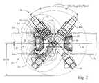
- FIG. 2is a schematic view of the first embodiment of the magnet system shown in FIG. 1 , showing a 80° range of motion for an imaging C-arm carrying a 20 cm receiver;
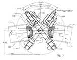
- FIG. 3is a schematic view of a second embodiment of a magnet system constructed according to the principles of this invention, showing a 75° range of motion for a C-arm carrying a 30 cm receiver;
- FIG. 4Ais a schematic view of an alternate implementation of the second embodiment in which the magnets can rotate about the operating region, showing a 120° range of motion for a C-arm carrying a 20 cm receiver, with the magnets rotated 22.5° in one direction from its normal position;
- FIG. 4Ais a schematic view of an alternate implementation of the second embodiment in which the magnets can rotate about the operating region, showing a 120° range of motion for a C-arm carrying a 20 cm receiver, with the magnets rotated 22.5° in the opposite direction from its normal position;
- FIG. 5is a perspective view of the magnet and its exclusion zone
- FIG. 6is an enlarged view of the magnet.
- FIG. 1A first embodiment of a magnetic navigation system constructed according to the principles of this invention is shown schematically in FIG. 1 .
- the magnetic navigation systemis adapted for orienting a magnetically responsive medical device in a selected direction within an operating region in a subject's body.
- the first embodiment of the systemcomprises a support 22 for supporting the subject, a magnet system 24 for applying a magnetic field to the operating region 26 , and an imaging system 28 for imaging the operating region 26 .
- the subject support 22is preferably a generally horizontal surface for supporting a subject in a generally horizontal position so that the operating region of the system is positioned within the subject's body.
- the magnet system 24comprises at least two magnets 30 and 32 disposed on opposite sides of the operating region 26 for applying a magnetic field sufficient for magnetic navigation in any selected direction within the operating region.
- Magnet 30is shown in FIG. 1 with its magnetic field lines, but for clarity, magnet 32 is shown without its magnetic field lines).
- Magnets 30 and 32are preferably identical in construction.
- the strength of the field required for magnetic navigationdepends in part upon the magnetic responsiveness of the device that is in the operating region 26 , which is typically provided with a magnetically responsive element, such as a permeable or permanent magnet, or an electromagnetic device.
- the magnets 30 and 32preferably can provide a navigating field of at least about 0.08 Tesla in any selected direction in the operating region, however in other embodiments the magnets 30 and 32 might be designed to provide a magnetic field of at least about 0.06 Tesla, or even lower as advances are made in improving the magnetic responsiveness of the medical devices deployed in the operating region 26 .
- the magnets 30 and 32are shaped and configured so that a change of the position and/or orientation of the magnets within an exclusion zone 34 permits the magnets to apply a magnetic field of the desired strength in the operating region 26 in any selected direction.
- a mechanism, not shown,is provided for repositioning and reorienting the magnets 30 and 32 as required to provide the desired field in the operating region.
- An example of one possible deviceis disclosed in U.S. patent application Ser. No. 10/347,525, for Magnetic Navigation System, incorporated herein by reference.
- Each of the magnetsis preferably made up of a plurality of blocks of magnetic material each of which is magnetized in one of a plurality of predetermined magnetization directions to maximize the magnet field in a particular direction at an operating point spaced from the front face of the magnet. It has been empirically determined that increments of 30° in magnetization direction are usually adequate, and any gains in field strength by obtained by smaller increments are usually not cost-effective. Details of the construction of such magnets are disclosed in U.S. Pat. No. 6,630,879, issued Oct. 7, 2003, An Efficient Magnet System for Magnetically-Assisted Surgery, and in U.S. patent application Ser. No. 10/056,227 for Rotating And Pivoting Magnet For Magnetic Navigation, the disclosures of which are incorporated herein by reference.
- Each of the magnets 30 and 32is sized and shaped to so that by translating the magnet along a first axis A extending radially from the operating region 26 , pivoting of the magnet about a second axis B perpendicular to the first axis A and extending substantially through the center of mass of the magnet, and rotation of the magnet about the first axis A, permits the magnets 30 and 32 to apply a magnetic field to the operating region 26 in any selected direction.
- the translation, pivoting, and rotation of the magnets required to achieve the desired range of directions in the operating regiondefine the exclusion zone 34 into which the imaging system 28 must not impinge so as to not interfere with the proper operation of the magnet system 24 .
- the magnetIn general the magnet is translated and pivoted to follow a line of constant magnetic field strength, e.g. the 0.08 Tesla line, at the operating point in the operating region.
- the rotation of the magnetallows the direction of the field to be changed. Pivoting the magnets at or near their centers of mass helps reduce the size of the exclusion zones 34 , and also allows for more compact and less expensive mechanisms for pivoting the magnets.
- the exclusion zone 34is generally cylindrical, with a frustoconical front face oriented toward the operating region 26 .
- the exclusion zoneis preferably contained within a protective shell, which protects the mechanism for moving the magnet, and hides the movement from view.
- the imaging system 28comprises an imaging beam source 36 and an imaging beam detector 38 disposed on opposite sides of the operating region 26 .
- the source 36 and the detector 38are carried on a C-arm 40 which can pivot about an axis generally parallel to the longitudinal axis of the subject on the support 22 , to change the imaging angle of the operating region 26 .
- Two C-armsare shown in FIG. 1 in order to illustrate the range of motion of the C-arm, but there is preferably only one C-arm used for imaging the operating region 26 ).
- the detector 38is preferably a solid state amorphous silicon x-ray receiving plate 42 , which is substantially unaffected by the magnetic fields created by the magnet system 24 .
- These solid state receiving platesare presently available in 20 cm ⁇ 20 cm and 30 cm ⁇ 30 cm sizes, with the 30 cm ⁇ 30 cm size being shown in FIG. 1 . Of course some other size imaging plate could be used.
- the imaging plateis disposed in a cover 44 , so that the width of the imaging zone extends 15 cm on either side of the centerline between the imaging source 36 and the imaging receiver 38 for a 20 cm ⁇ 20 cm plate, and so that the width of the imaging zone extends 20 cm on either side of the centerline between the imaging source 36 and the imaging receiver 38 for a 30 cm ⁇ 30 cm plate.
- the receiving plate 42is preferably mounted for translation toward and away from the operating region 26 , in order to change the resolution of the images of the operating region.
- the movement of the receiving plate 42 and cover 44define an imaging zone 46 extending generally from the operating region 26 , centered along the line between the source 36 and the receiver 38 through the center of the operating region 26 .
- the magnet system, and in particular the exclusion zones of the magnet systempreferably does not impinge upon this imaging zone 46 .
- the magnets 30 and 32are configured and positioned so that the C-arm 40 can pivot through at least about 60° without impinging upon the exclusion zone of the magnets, and more specifically, so that the magnets 30 and 32 and their exclusions zones 34 don't impinge upon the C-arm 40 , the imaging beam source 36 and detector 38 , or the imaging zone 46 .
- the C-arm 40 , the imaging beam source 36 and detector 38 , and the imaging zone 46do not impinge upon the magnets 30 and 32 and their exclusions zones.
- the magnets 30 and 32and more particularly the first axes A of the magnets 30 and 32 intersect at an angle of 178°.
- This additional 2°permits the C-arm 40 to travel a full 60°.
- this travelis preferably symmetric about the mid-sagittal plane, so that the imaging system can provide left anterior oblique and right anterior oblique images at 30° from the mid-sagittal plane.
- the magnets 30 and 32can be mounted for movement (preferably in fixed relationship to each other) about the operating region, to provide greater clearance for the imaging system to thereby extend the pivot range of the C-arm 40 .
- the imaging systemcan alternatively be provided with a 20 cm ⁇ 20 cm imaging plate.
- the smaller imaging plate 42results in a smaller imaging zone 46 , and thus permits a broader range of pivoting of the C-arm.
- the C-arm 40can pivot over a range of 80°, preferably centered on the mid-sagittal plane.
- FIG. 3A second embodiment of a magnetic navigation system constructed according to the principles of this invention is shown schematically in FIG. 3 .
- the magnetic navigation systemis adapted for orienting a magnetically responsive medical device in a selected direction within an operating region in a subject's body.
- the second embodiment of the systemcomprises a support 122 for supporting the subject, a magnet system 124 for applying a magnetic field to the operating region 126 , and an imaging system 128 for imaging the operating region 126 .
- the subject support 122is preferably a generally horizontal surface for supporting a subject in a generally horizontal position so that the operating region of the system is positioned within the subject's body.
- the magnet system 124comprises at least two magnets 130 and 132 disposed on opposite sides of the operating region 126 for applying a magnetic field sufficient for magnetic navigation in any selected direction within the operating region.
- Magnets 130 and 132are preferably identical in construction.
- the strength of the field required for magnetic navigationdepends in part upon the magnetic responsiveness of the device that is in the operating region 126 , which is typically provided with a magnetically responsive element, such as a permeable or permanent magnet, or an electromagnetic device.
- the magnets 130 and 132preferably can provide a navigating field of at least about 0.08 Tesla in any selected direction in the operating region, however in other embodiments the magnets 130 and 132 might be designed to provide a magnetic field of at least about 0.06 Tesla, or even lower as advances are made in improving the magnetic responsiveness of the medical devices deployed in the operating region 126 .
- the magnets 130 and 132are shaped and configured so that a change of the position and/or orientation of the magnets within an exclusion zone 134 permits the magnets to apply a magnetic field of the desired strength in the operating region 126 in any selected direction.
- a mechanism, not shown,is provided for repositioning and reorienting the magnets 130 and 132 as required to provide the desired field in the operating region.
- An example of one possible deviceis disclosed in U.S. patent application Ser. No. 10/347,525, for Magnetic Navigation System, incorporated herein by reference.
- Each of the magnetsis preferably made up of a plurality of blocks of magnetic material each of which is magnetized in one of a plurality of predetermined magnetization directions to maximize the magnet field in a particular direction at an operating point spaced from the front face of the magnet. It has been empirically determined that increments of 30° in magnetization direction are usually adequate, and any gains in field strength by obtained by smaller increments are usually not cost-effective. Details of the construction of such magnets are disclosed in U.S. Pat. No. 6,630,879, issued Oct. 7, 2003, An Efficient Magnet System for Magnetically-Assisted Surgery, and in U.S. patent application Ser. No. 10/056,227 for Rotating And Pivoting Magnet For Magnetic Navigation, the disclosures of which are incorporated herein by reference.
- Each of the magnets 130 and 132is sized and shaped to so that by translating the magnet along a first axis A extending radially from the operating region 26 , pivoting of the magnet about a second axis B perpendicular to the first axis A and extending substantially through the center of mass of the magnet, and rotation of the magnet about the first axis A, permits the magnets 130 and 132 to apply a magnetic field to the operating region 126 in any selected direction.
- the translation, pivoting, and rotation of the magnets required to achieve the desired range of directions in the operating regiondefine the exclusion zone 134 into which the imaging system 128 must not impinge so as to not interfere with the proper operation of the magnet system 124 . Pivoting the magnets at or near their centers of mass helps reduce the size of the exclusion zones 134 , and also allows for more compact and less expensive mechanisms for pivoting the magnets.
- the exclusion zone 134is generally cylindrical, with a frustoconical front face oriented toward the operating region 126 .
- the exclusion zoneis preferably contained within a protective shell, which protects the mechanism for moving the magnet, and hides the movement from view.
- the imaging system 128comprises an imaging beam source 136 and an imaging beam detector 138 disposed on opposite sides of the operating region 126 .
- the source 136 and the detector 38are carried on a C-arm 140 which can pivot about an axis generally parallel to the longitudinal axis of the subject on the support 122 , to change the imaging angle of the operating region 126 .
- Two C-armsare shown in FIG. 3 in order to illustrate the range of motion of the C-arm, but there is preferably only one C-arm used for imaging the operating region 126 ).
- the detector 138is preferably a solid state amorphous silicon x-ray receiving plate 142 , which is substantially unaffected by the magnetic fields created by the magnet system 124 .
- These solid state receiving platesare presently available in 20 cm ⁇ 20 cm and 30 cm ⁇ 30 cm sizes, with the 30 cm ⁇ 30 cm size being shown in FIG. 3 .
- the imaging plateis disposed in a cover 144 , so that the width of the imaging zone extends 15 cm on either side of the centerline between the imaging source 36 and the imaging receiver 138 for a 20 cm ⁇ 20 cm plate, and so that the width of the imaging zone extends 20 cm on either side of the centerline between the imaging source 136 and the imaging receiver 38 for a 30 cm ⁇ 30 cm plate.
- the receiving plate 142is preferably mounted for translation toward and away from the operating region 126 , in order to change the resolution of the images of the operating region.
- the movement of the receiving plate 142 and cover 144define an imaging zone 146 extending generally from the operating region 126 , centered along the line between the source 136 and the receiver 138 through the center of the operating region 126 .
- the magnet system, and in particular the exclusion zones of the magnet systempreferably does not impinge upon this imaging zone 146 .
- the magnets 130 and 132are configured and positioned so that the C-arm 140 can pivot through at least about 60° without impinging upon the exclusion zone of the magnets, and more specifically, so that the magnets 130 and 132 and their exclusions zones 134 don't impinge upon the C-arm 140 , the imaging beam source 136 and detector 138 , or the imaging zone 146 . Similarly, the C-arm 140 , the imaging beam source 136 and detector 138 , and the imaging zone 146 do not impinge upon the magnets 130 and 132 and their exclusions zones.
- the magnets 130 and 132and more particularly the first axes A of the magnets 130 and 132 intersect at an angle of 163°.
- This additional 17°permits the C-arm 140 to travel a full 75°.
- this travelis preferably symmetric about the mid-sagittal plane, so that the imaging system can provide left anterior oblique and right anterior oblique images at 30° from the mid-sagittal plane.
- the magnets 130 and 132can be mounted for movement (preferably in fixed relationship to each other) about the operating region, to provide greater clearance for the imaging system to thereby extend the pivot range of the C-arm 40 .
- the imaging systemcan alternatively be provided with a 20 cm ⁇ 20 cm imaging plate.
- the smaller imaging plate 142results in a smaller imaging zone 146 , and thus permits a broader range of pivoting of the C-arm.
- FIGS. 4A and 4Bby permitting the magnets 130 and 132 to rotate (preferably in fixed relationship to each other) +/ ⁇ 22.5° about the operating region 126 , the C-arm 40 can pivot over a range of 120°, preferably centered on the mid-sagittal plane.
- FIGS. 4A and 4Bonly show the magnet 130 , it being understood that magnet 132 moves in fixed relationship with magnet 130 , so that the angle between their respective A axes remains 163°.
- Magnet 30is shown in more detail in FIG. 5 .
- the magnetcomprised of a plurality of sections or layers each having a different magnetization direction than the adjacent layers.
- the magnet 30has five layers 206 , 208 , 210 , 212 , and 214 , each having a magnetization direction varying by 30° from its adjacent layers.
- the layers 206 , 208 , 210 , 212 , and 214extend parallel to the axis B, which extends through the center of mass 202 of the magnet 30 .
- the magnethas a flat, generally circular front face 200 , surrounded by a generally conical surface 204 .
- the sides of the magnet 30have a plurality of flat faces to save the weight of material that does not contribute significantly to the field strength of the magnet.
- the magnetization direction of the layers 206 , 208 , 210 , 212 , and 214varies in a plane perpendicular to the axis B.
- the section 206is magnetized in a direction downwardly and rearwardly as shown in FIG. 6 , at an angle of 60° with respect to vertical.
- the section 208is magnetized in a direction downwardly and rearwardly as shown in FIG. 6 , at an angle of 30° with respect to vertical.
- the section 210is magnetized in a direction downwardly as shown in FIG. 1 , at an angle of 0° with respect to vertical.
- the section 212is magnetized in a direction downwardly and forwardly as shown in FIG. 6 , at an angle of 30° with respect to vertical.
- the section 214is magnetized in a direction downwardly and forwardly as shown in FIG. 6 , at an angle of 60° with respect to vertical.
- FIGS. 5 and 6is an idealized design, and in actual practice the magnet of substantially the desired shape could be built up from smaller blocks of magnetic material approximating the shape of the idealized design, as is known.
Landscapes
- Health & Medical Sciences (AREA)
- Surgery (AREA)
- Life Sciences & Earth Sciences (AREA)
- Engineering & Computer Science (AREA)
- Heart & Thoracic Surgery (AREA)
- Animal Behavior & Ethology (AREA)
- Veterinary Medicine (AREA)
- Biomedical Technology (AREA)
- Nuclear Medicine, Radiotherapy & Molecular Imaging (AREA)
- Medical Informatics (AREA)
- Molecular Biology (AREA)
- Public Health (AREA)
- General Health & Medical Sciences (AREA)
- Pathology (AREA)
- Oral & Maxillofacial Surgery (AREA)
- Robotics (AREA)
- Apparatus For Radiation Diagnosis (AREA)
- Magnetic Resonance Imaging Apparatus (AREA)
Abstract
Description
Claims (30)
Priority Applications (1)
| Application Number | Priority Date | Filing Date | Title |
|---|---|---|---|
| US10/801,062US7305263B2 (en) | 2003-03-13 | 2004-03-15 | Magnetic navigation system and magnet system therefor |
Applications Claiming Priority (2)
| Application Number | Priority Date | Filing Date | Title |
|---|---|---|---|
| US45441003P | 2003-03-13 | 2003-03-13 | |
| US10/801,062US7305263B2 (en) | 2003-03-13 | 2004-03-15 | Magnetic navigation system and magnet system therefor |
Publications (2)
| Publication Number | Publication Date |
|---|---|
| US20040249263A1 US20040249263A1 (en) | 2004-12-09 |
| US7305263B2true US7305263B2 (en) | 2007-12-04 |
Family
ID=33493087
Family Applications (1)
| Application Number | Title | Priority Date | Filing Date |
|---|---|---|---|
| US10/801,062Expired - LifetimeUS7305263B2 (en) | 2003-03-13 | 2004-03-15 | Magnetic navigation system and magnet system therefor |
Country Status (1)
| Country | Link |
|---|---|
| US (1) | US7305263B2 (en) |
Cited By (15)
| Publication number | Priority date | Publication date | Assignee | Title |
|---|---|---|---|---|
| US7772950B2 (en) | 2005-08-10 | 2010-08-10 | Stereotaxis, Inc. | Method and apparatus for dynamic magnetic field control using multiple magnets |
| US7961926B2 (en) | 2005-02-07 | 2011-06-14 | Stereotaxis, Inc. | Registration of three-dimensional image data to 2D-image-derived data |
| US8024024B2 (en) | 2007-06-27 | 2011-09-20 | Stereotaxis, Inc. | Remote control of medical devices using real time location data |
| DE102010051684A1 (en) | 2010-11-17 | 2012-05-24 | Follak Matthias | Device for controlling movements of catheter-like tool within blood vessel of patient for treatment of e.g. cerebral stroke, has electromagnet and catheter whose spatial orientations are controlled using synchronizing control |
| US8231618B2 (en) | 2007-11-05 | 2012-07-31 | Stereotaxis, Inc. | Magnetically guided energy delivery apparatus |
| US8308628B2 (en) | 2009-11-02 | 2012-11-13 | Pulse Therapeutics, Inc. | Magnetic-based systems for treating occluded vessels |
| US8369934B2 (en) | 2004-12-20 | 2013-02-05 | Stereotaxis, Inc. | Contact over-torque with three-dimensional anatomical data |
| US20130138117A1 (en)* | 2010-02-17 | 2013-05-30 | The University Of Utah Research Foundation | Cochlear implant insertion method and system |
| US20130139832A1 (en)* | 2009-02-25 | 2013-06-06 | Benjamin Shapiro | Devices, systems and methods for magnetic-assisted therapeutic agent delivery |
| US9314222B2 (en) | 2005-07-07 | 2016-04-19 | Stereotaxis, Inc. | Operation of a remote medical navigation system using ultrasound image |
| US9883878B2 (en) | 2012-05-15 | 2018-02-06 | Pulse Therapeutics, Inc. | Magnetic-based systems and methods for manipulation of magnetic particles |
| US10537713B2 (en) | 2009-05-25 | 2020-01-21 | Stereotaxis, Inc. | Remote manipulator device |
| US11890226B2 (en) | 2009-02-25 | 2024-02-06 | University Of Maryland, College Park | Device and methods for directing agents into an eye |
| US11918315B2 (en) | 2018-05-03 | 2024-03-05 | Pulse Therapeutics, Inc. | Determination of structure and traversal of occlusions using magnetic particles |
| US12171443B1 (en) | 2021-03-09 | 2024-12-24 | Pulse Therapeutics, Inc. | Magnetically controlled flow generation |
Families Citing this family (48)
| Publication number | Priority date | Publication date | Assignee | Title |
|---|---|---|---|---|
| US6703418B2 (en)* | 1991-02-26 | 2004-03-09 | Unimed Pharmaceuticals, Inc. | Appetite stimulation and induction of weight gain in patients suffering from symptomatic HIV infection |
| US7066924B1 (en)* | 1997-11-12 | 2006-06-27 | Stereotaxis, Inc. | Method of and apparatus for navigating medical devices in body lumens by a guide wire with a magnetic tip |
| US7313429B2 (en)* | 2002-01-23 | 2007-12-25 | Stereotaxis, Inc. | Rotating and pivoting magnet for magnetic navigation |
| US6702804B1 (en) | 1999-10-04 | 2004-03-09 | Stereotaxis, Inc. | Method for safely and efficiently navigating magnetic devices in the body |
| US6401723B1 (en)* | 2000-02-16 | 2002-06-11 | Stereotaxis, Inc. | Magnetic medical devices with changeable magnetic moments and method of navigating magnetic medical devices with changeable magnetic moments |
| US7766856B2 (en) | 2001-05-06 | 2010-08-03 | Stereotaxis, Inc. | System and methods for advancing a catheter |
| DK1389958T3 (en) | 2001-05-06 | 2009-01-12 | Stereotaxis Inc | Catheter delivery system |
| US7635342B2 (en)* | 2001-05-06 | 2009-12-22 | Stereotaxis, Inc. | System and methods for medical device advancement and rotation |
| US7248914B2 (en) | 2002-06-28 | 2007-07-24 | Stereotaxis, Inc. | Method of navigating medical devices in the presence of radiopaque material |
| WO2004045387A2 (en) | 2002-11-18 | 2004-06-03 | Stereotaxis, Inc. | Magnetically navigable balloon catheters |
| US7389778B2 (en) | 2003-05-02 | 2008-06-24 | Stereotaxis, Inc. | Variable magnetic moment MR navigation |
| US6980843B2 (en)* | 2003-05-21 | 2005-12-27 | Stereotaxis, Inc. | Electrophysiology catheter |
| US20060025679A1 (en) | 2004-06-04 | 2006-02-02 | Viswanathan Raju R | User interface for remote control of medical devices |
| US20060036163A1 (en)* | 2004-07-19 | 2006-02-16 | Viswanathan Raju R | Method of, and apparatus for, controlling medical navigation systems |
| US20060144407A1 (en)* | 2004-07-20 | 2006-07-06 | Anthony Aliberto | Magnetic navigation manipulation apparatus |
| US20080006280A1 (en)* | 2004-07-20 | 2008-01-10 | Anthony Aliberto | Magnetic navigation maneuvering sheath |
| US20060144408A1 (en)* | 2004-07-23 | 2006-07-06 | Ferry Steven J | Micro-catheter device and method of using same |
| US7627361B2 (en)* | 2004-08-24 | 2009-12-01 | Stereotaxis, Inc. | Methods and apparatus for steering medical device in body lumens |
| US7831294B2 (en) | 2004-10-07 | 2010-11-09 | Stereotaxis, Inc. | System and method of surgical imagining with anatomical overlay for navigation of surgical devices |
| WO2006076394A2 (en) | 2005-01-11 | 2006-07-20 | Stereotaxis, Inc. | Navigation using sensed physiological data as feedback |
| WO2006121974A2 (en)* | 2005-05-06 | 2006-11-16 | Stereotaxis, Inc. | User interfaces and navigation methods for vascular navigation |
| US7742803B2 (en)* | 2005-05-06 | 2010-06-22 | Stereotaxis, Inc. | Voice controlled user interface for remote navigation systems |
| US8027714B2 (en)* | 2005-05-27 | 2011-09-27 | Magnetecs, Inc. | Apparatus and method for shaped magnetic field control for catheter, guidance, control, and imaging |
| US20070060992A1 (en)* | 2005-06-02 | 2007-03-15 | Carlo Pappone | Methods and devices for mapping the ventricle for pacing lead placement and therapy delivery |
| US20070038065A1 (en)* | 2005-07-07 | 2007-02-15 | Creighton Francis M Iv | Operation of a remote medical navigation system using ultrasound image |
| US20070021744A1 (en)* | 2005-07-07 | 2007-01-25 | Creighton Francis M Iv | Apparatus and method for performing ablation with imaging feedback |
| US7603905B2 (en)* | 2005-07-08 | 2009-10-20 | Stereotaxis, Inc. | Magnetic navigation and imaging system |
| US7769444B2 (en) | 2005-07-11 | 2010-08-03 | Stereotaxis, Inc. | Method of treating cardiac arrhythmias |
| US7690619B2 (en)* | 2005-07-12 | 2010-04-06 | Stereotaxis, Inc. | Apparatus for pivotally orienting a projection device |
| US7416335B2 (en)* | 2005-07-15 | 2008-08-26 | Sterotaxis, Inc. | Magnetically shielded x-ray tube |
| US8192374B2 (en)* | 2005-07-18 | 2012-06-05 | Stereotaxis, Inc. | Estimation of contact force by a medical device |
| US7818076B2 (en) | 2005-07-26 | 2010-10-19 | Stereotaxis, Inc. | Method and apparatus for multi-system remote surgical navigation from a single control center |
| US20070043455A1 (en)* | 2005-07-26 | 2007-02-22 | Viswanathan Raju R | Apparatus and methods for automated sequential movement control for operation of a remote navigation system |
| US20070040670A1 (en)* | 2005-07-26 | 2007-02-22 | Viswanathan Raju R | System and network for remote medical procedures |
| US20070055124A1 (en)* | 2005-09-01 | 2007-03-08 | Viswanathan Raju R | Method and system for optimizing left-heart lead placement |
| DE102006000709A1 (en)* | 2006-01-03 | 2007-07-12 | Siemens Ag | Navigation device comprising a magnetic field generating device for generating a magnetic field for moving a medical instrument, in particular a catheter |
| US20080015427A1 (en)* | 2006-06-30 | 2008-01-17 | Nathan Kastelein | System and network for remote medical procedures |
| WO2008007771A1 (en)* | 2006-07-13 | 2008-01-17 | Hitachi Metals, Ltd. | Magnetic field control method and magnetic field generator |
| US7961924B2 (en) | 2006-08-21 | 2011-06-14 | Stereotaxis, Inc. | Method of three-dimensional device localization using single-plane imaging |
| US7567233B2 (en) | 2006-09-06 | 2009-07-28 | Stereotaxis, Inc. | Global input device for multiple computer-controlled medical systems |
| US7747960B2 (en) | 2006-09-06 | 2010-06-29 | Stereotaxis, Inc. | Control for, and method of, operating at least two medical systems |
| US8242972B2 (en) | 2006-09-06 | 2012-08-14 | Stereotaxis, Inc. | System state driven display for medical procedures |
| US8244824B2 (en) | 2006-09-06 | 2012-08-14 | Stereotaxis, Inc. | Coordinated control for multiple computer-controlled medical systems |
| US8273081B2 (en) | 2006-09-08 | 2012-09-25 | Stereotaxis, Inc. | Impedance-based cardiac therapy planning method with a remote surgical navigation system |
| WO2008033829A2 (en) | 2006-09-11 | 2008-03-20 | Stereotaxis, Inc. | Automated mapping of anatomical features of heart chambers |
| US8135185B2 (en) | 2006-10-20 | 2012-03-13 | Stereotaxis, Inc. | Location and display of occluded portions of vessels on 3-D angiographic images |
| WO2009009497A1 (en) | 2007-07-06 | 2009-01-15 | Stereotaxis, Inc. | Management of live remote medical display |
| US20110112396A1 (en) | 2009-11-09 | 2011-05-12 | Magnetecs, Inc. | System and method for targeting catheter electrodes |
Citations (8)
| Publication number | Priority date | Publication date | Assignee | Title |
|---|---|---|---|---|
| US6241671B1 (en)* | 1998-11-03 | 2001-06-05 | Stereotaxis, Inc. | Open field system for magnetic surgery |
| US20030137380A1 (en) | 2002-01-23 | 2003-07-24 | Creighton Francis M. | Rotating and pivoting magnet for magnetic navigation |
| US6630879B1 (en)* | 1999-02-04 | 2003-10-07 | Stereotaxis, Inc. | Efficient magnet system for magnetically-assisted surgery |
| US20040030324A1 (en) | 2002-01-23 | 2004-02-12 | Creighton Francis M. | Magnetic navigation system |
| US20040158972A1 (en) | 2002-11-07 | 2004-08-19 | Creighton Francis M. | Method of making a compound magnet |
| US20040199074A1 (en)* | 1999-10-04 | 2004-10-07 | Ritter Rogers C. | Method for safely and efficiently navigating magnetic devices in the body |
| US20070038064A1 (en)* | 2005-07-08 | 2007-02-15 | Creighton Francis M Iv | Magnetic navigation and imaging system |
| US20070146106A1 (en)* | 1999-10-04 | 2007-06-28 | Creighton Francis M Iv | Rotating and pivoting magnet for magnetic navigation |
Family Cites Families (1)
| Publication number | Priority date | Publication date | Assignee | Title |
|---|---|---|---|---|
| US6769907B2 (en)* | 2001-12-19 | 2004-08-03 | Kevin Eugene Doud | Open fire display apparatus with thermal expansion feature |
- 2004
- 2004-03-15USUS10/801,062patent/US7305263B2/ennot_activeExpired - Lifetime
Patent Citations (11)
| Publication number | Priority date | Publication date | Assignee | Title |
|---|---|---|---|---|
| US6241671B1 (en)* | 1998-11-03 | 2001-06-05 | Stereotaxis, Inc. | Open field system for magnetic surgery |
| US20010038683A1 (en)* | 1998-11-03 | 2001-11-08 | Ritter Rogers C. | Open field system for magnetic surgery |
| US6630879B1 (en)* | 1999-02-04 | 2003-10-07 | Stereotaxis, Inc. | Efficient magnet system for magnetically-assisted surgery |
| US20040199074A1 (en)* | 1999-10-04 | 2004-10-07 | Ritter Rogers C. | Method for safely and efficiently navigating magnetic devices in the body |
| US20070146106A1 (en)* | 1999-10-04 | 2007-06-28 | Creighton Francis M Iv | Rotating and pivoting magnet for magnetic navigation |
| US20030137380A1 (en) | 2002-01-23 | 2003-07-24 | Creighton Francis M. | Rotating and pivoting magnet for magnetic navigation |
| US20040030324A1 (en) | 2002-01-23 | 2004-02-12 | Creighton Francis M. | Magnetic navigation system |
| US6975197B2 (en)* | 2002-01-23 | 2005-12-13 | Stereotaxis, Inc. | Rotating and pivoting magnet for magnetic navigation |
| US7019610B2 (en)* | 2002-01-23 | 2006-03-28 | Stereotaxis, Inc. | Magnetic navigation system |
| US20040158972A1 (en) | 2002-11-07 | 2004-08-19 | Creighton Francis M. | Method of making a compound magnet |
| US20070038064A1 (en)* | 2005-07-08 | 2007-02-15 | Creighton Francis M Iv | Magnetic navigation and imaging system |
Cited By (30)
| Publication number | Priority date | Publication date | Assignee | Title |
|---|---|---|---|---|
| US8369934B2 (en) | 2004-12-20 | 2013-02-05 | Stereotaxis, Inc. | Contact over-torque with three-dimensional anatomical data |
| US7961926B2 (en) | 2005-02-07 | 2011-06-14 | Stereotaxis, Inc. | Registration of three-dimensional image data to 2D-image-derived data |
| US9314222B2 (en) | 2005-07-07 | 2016-04-19 | Stereotaxis, Inc. | Operation of a remote medical navigation system using ultrasound image |
| US7772950B2 (en) | 2005-08-10 | 2010-08-10 | Stereotaxis, Inc. | Method and apparatus for dynamic magnetic field control using multiple magnets |
| US8024024B2 (en) | 2007-06-27 | 2011-09-20 | Stereotaxis, Inc. | Remote control of medical devices using real time location data |
| US8231618B2 (en) | 2007-11-05 | 2012-07-31 | Stereotaxis, Inc. | Magnetically guided energy delivery apparatus |
| US11890226B2 (en) | 2009-02-25 | 2024-02-06 | University Of Maryland, College Park | Device and methods for directing agents into an eye |
| US10688292B2 (en)* | 2009-02-25 | 2020-06-23 | University Of Maryland | Devices, systems and methods for magnetic-assisted therapeutic agent delivery |
| US20130139832A1 (en)* | 2009-02-25 | 2013-06-06 | Benjamin Shapiro | Devices, systems and methods for magnetic-assisted therapeutic agent delivery |
| US10537713B2 (en) | 2009-05-25 | 2020-01-21 | Stereotaxis, Inc. | Remote manipulator device |
| US9339664B2 (en) | 2009-11-02 | 2016-05-17 | Pulse Therapetics, Inc. | Control of magnetic rotors to treat therapeutic targets |
| US10159734B2 (en) | 2009-11-02 | 2018-12-25 | Pulse Therapeutics, Inc. | Magnetic particle control and visualization |
| US8926491B2 (en) | 2009-11-02 | 2015-01-06 | Pulse Therapeutics, Inc. | Controlling magnetic nanoparticles to increase vascular flow |
| US8529428B2 (en) | 2009-11-02 | 2013-09-10 | Pulse Therapeutics, Inc. | Methods of controlling magnetic nanoparticles to improve vascular flow |
| US12370259B2 (en) | 2009-11-02 | 2025-07-29 | Pulse Therapeutics, Inc. | Magnetic particle control and visualization |
| US9345498B2 (en) | 2009-11-02 | 2016-05-24 | Pulse Therapeutics, Inc. | Methods of controlling magnetic nanoparticles to improve vascular flow |
| US11612655B2 (en) | 2009-11-02 | 2023-03-28 | Pulse Therapeutics, Inc. | Magnetic particle control and visualization |
| US11000589B2 (en) | 2009-11-02 | 2021-05-11 | Pulse Therapeutics, Inc. | Magnetic particle control and visualization |
| US10029008B2 (en) | 2009-11-02 | 2018-07-24 | Pulse Therapeutics, Inc. | Therapeutic magnetic control systems and contrast agents |
| US8715150B2 (en) | 2009-11-02 | 2014-05-06 | Pulse Therapeutics, Inc. | Devices for controlling magnetic nanoparticles to treat fluid obstructions |
| US8313422B2 (en) | 2009-11-02 | 2012-11-20 | Pulse Therapeutics, Inc. | Magnetic-based methods for treating vessel obstructions |
| US10813997B2 (en) | 2009-11-02 | 2020-10-27 | Pulse Therapeutics, Inc. | Devices for controlling magnetic nanoparticles to treat fluid obstructions |
| US8308628B2 (en) | 2009-11-02 | 2012-11-13 | Pulse Therapeutics, Inc. | Magnetic-based systems for treating occluded vessels |
| US9656058B2 (en)* | 2010-02-17 | 2017-05-23 | University Of Utah Research Foundation | Cochlear implant insertion method and system |
| US20130138117A1 (en)* | 2010-02-17 | 2013-05-30 | The University Of Utah Research Foundation | Cochlear implant insertion method and system |
| DE102010051684A1 (en) | 2010-11-17 | 2012-05-24 | Follak Matthias | Device for controlling movements of catheter-like tool within blood vessel of patient for treatment of e.g. cerebral stroke, has electromagnet and catheter whose spatial orientations are controlled using synchronizing control |
| US10646241B2 (en) | 2012-05-15 | 2020-05-12 | Pulse Therapeutics, Inc. | Detection of fluidic current generated by rotating magnetic particles |
| US9883878B2 (en) | 2012-05-15 | 2018-02-06 | Pulse Therapeutics, Inc. | Magnetic-based systems and methods for manipulation of magnetic particles |
| US11918315B2 (en) | 2018-05-03 | 2024-03-05 | Pulse Therapeutics, Inc. | Determination of structure and traversal of occlusions using magnetic particles |
| US12171443B1 (en) | 2021-03-09 | 2024-12-24 | Pulse Therapeutics, Inc. | Magnetically controlled flow generation |
Also Published As
| Publication number | Publication date |
|---|---|
| US20040249263A1 (en) | 2004-12-09 |
Similar Documents
| Publication | Publication Date | Title |
|---|---|---|
| US7305263B2 (en) | Magnetic navigation system and magnet system therefor | |
| US6975197B2 (en) | Rotating and pivoting magnet for magnetic navigation | |
| US7161453B2 (en) | Rotating and pivoting magnet for magnetic navigation | |
| US10702132B2 (en) | System and method for using a capsule device | |
| US6537196B1 (en) | Magnet assembly with variable field directions and methods of magnetically navigating medical objects | |
| US6630879B1 (en) | Efficient magnet system for magnetically-assisted surgery | |
| US10478135B2 (en) | Urology table with tiltable X-ray tube | |
| US20180084975A1 (en) | SYSTEM and METHOD FOR USING A CAPSULE DEVICE | |
| US3670163A (en) | Radiological examination apparatus | |
| JP2003503095A (en) | Digital X-ray scanner | |
| JPH09103426A (en) | Portable c-type arm device for x-ray diagnostic device | |
| JP2002538885A (en) | Method and system for controlling magnetic elements in a body using a gapped toroid magnet | |
| JP2001522623A (en) | Movable magnetic guidance system and device and method of using same for magnetic assisted surgery | |
| CN111134701B (en) | Portable medical imaging systems and methods | |
| EP1578273B1 (en) | Digital imaging method and apparatus for mammography | |
| AU769606B2 (en) | Method and device for determining access to a subsurface target | |
| WO2001060256A1 (en) | Method for imaging the head area | |
| US20030091151A1 (en) | Universal radiography system | |
| US5911655A (en) | Device for supporting a patient for stereotactic on-target radiation treatment | |
| JPH04501669A (en) | Lithotripter with two stereotactic devices in a concentric system | |
| US7616983B2 (en) | Device for guiding a magnetic element | |
| JP2816730B2 (en) | Radiology equipment with conformable points that can move in space | |
| EP1488431B1 (en) | Rotating and pivoting magnet for magnetic navigation | |
| JPS5931600A (en) | X-ray collimator used for head x-ray photographing | |
| JPH05111483A (en) | Cranium fixing device for medical purpose |
Legal Events
| Date | Code | Title | Description |
|---|---|---|---|
| AS | Assignment | Owner name:STEREOTAXIS, INC., MISSOURI Free format text:ASSIGNMENT OF ASSIGNORS INTEREST;ASSIGNOR:CREIGHTON, IV, FRANCIS M;REEL/FRAME:014923/0185 Effective date:20040719 | |
| STCF | Information on status: patent grant | Free format text:PATENTED CASE | |
| CC | Certificate of correction | ||
| FPAY | Fee payment | Year of fee payment:4 | |
| AS | Assignment | Owner name:SILICON VALLEY BANK, ILLINOIS Free format text:SECURITY AGREEMENT;ASSIGNOR:STEREOTAXIS, INC.;REEL/FRAME:027332/0178 Effective date:20111130 | |
| AS | Assignment | Owner name:COWEN HEALTHCARE ROYALTY PARTNERS II, L.P., AS LENDER, CONNECTICUT Free format text:SECURITY AGREEMENT;ASSIGNOR:STEREOTAXIS, INC.;REEL/FRAME:027346/0001 Effective date:20111205 Owner name:COWEN HEALTHCARE ROYALTY PARTNERS II, L.P., AS LEN Free format text:SECURITY AGREEMENT;ASSIGNOR:STEREOTAXIS, INC.;REEL/FRAME:027346/0001 Effective date:20111205 | |
| FEPP | Fee payment procedure | Free format text:PAT HOLDER CLAIMS SMALL ENTITY STATUS, ENTITY STATUS SET TO SMALL (ORIGINAL EVENT CODE: LTOS); ENTITY STATUS OF PATENT OWNER: SMALL ENTITY | |
| REMI | Maintenance fee reminder mailed | ||
| FPAY | Fee payment | Year of fee payment:8 | |
| SULP | Surcharge for late payment | Year of fee payment:7 | |
| AS | Assignment | Owner name:COWEN HEALTHCARE ROYALTY PARTNERS II, L.P., CONNECTICUT Free format text:RELEASE BY SECURED PARTY;ASSIGNOR:STEREOTAXIS, INC.;REEL/FRAME:043733/0376 Effective date:20170828 Owner name:COWEN HEALTHCARE ROYALTY PARTNERS II, L.P., CONNEC Free format text:RELEASE BY SECURED PARTY;ASSIGNOR:STEREOTAXIS, INC.;REEL/FRAME:043733/0376 Effective date:20170828 | |
| AS | Assignment | Owner name:SILICON VALLEY BANK, CALIFORNIA Free format text:SECURITY INTEREST;ASSIGNORS:STEREOTAXIS, INC.;STEREOTAXIS INTERNATIONAL, INC.;REEL/FRAME:044452/0073 Effective date:20171107 | |
| AS | Assignment | Owner name:STEREOTAXIS, INC., MISSOURI Free format text:CORRECTIVE ASSIGNMENT TO CORRECT THE REVERSAL OF ASSIGNOR AND ASSIGNEE PREVIOUSLY RECORDED ON REEL 043733 FRAME 0376. ASSIGNOR(S) HEREBY CONFIRMS THE RELEASE OF SECURITY INTEREST;ASSIGNOR:COWEN HEALTHCARE ROYALTY PARTNERS II, L.P.;REEL/FRAME:044269/0282 Effective date:20170828 | |
| MAFP | Maintenance fee payment | Free format text:PAYMENT OF MAINTENANCE FEE, 12TH YR, SMALL ENTITY (ORIGINAL EVENT CODE: M2553); ENTITY STATUS OF PATENT OWNER: SMALL ENTITY Year of fee payment:12 |