US7305043B2 - Method and apparatus for formatting signals for digital audio broadcasting transmission and reception - Google Patents
Method and apparatus for formatting signals for digital audio broadcasting transmission and receptionDownload PDFInfo
- Publication number
- US7305043B2 US7305043B2US10/465,443US46544303AUS7305043B2US 7305043 B2US7305043 B2US 7305043B2US 46544303 AUS46544303 AUS 46544303AUS 7305043 B2US7305043 B2US 7305043B2
- Authority
- US
- United States
- Prior art keywords
- bits
- data units
- protocol data
- digital audio
- audio broadcasting
- Prior art date
- Legal status (The legal status is an assumption and is not a legal conclusion. Google has not performed a legal analysis and makes no representation as to the accuracy of the status listed.)
- Expired - Lifetime, expires
Links
Images


Classifications
- H—ELECTRICITY
- H04—ELECTRIC COMMUNICATION TECHNIQUE
- H04L—TRANSMISSION OF DIGITAL INFORMATION, e.g. TELEGRAPHIC COMMUNICATION
- H04L27/00—Modulated-carrier systems
- H04L27/02—Amplitude-modulated carrier systems, e.g. using on-off keying; Single sideband or vestigial sideband modulation
- H04L27/04—Modulator circuits; Transmitter circuits
- H—ELECTRICITY
- H04—ELECTRIC COMMUNICATION TECHNIQUE
- H04L—TRANSMISSION OF DIGITAL INFORMATION, e.g. TELEGRAPHIC COMMUNICATION
- H04L25/00—Baseband systems
- H04L25/02—Details ; arrangements for supplying electrical power along data transmission lines
- H04L25/03—Shaping networks in transmitter or receiver, e.g. adaptive shaping networks
- H04L25/03828—Arrangements for spectral shaping; Arrangements for providing signals with specified spectral properties
- H04L25/03866—Arrangements for spectral shaping; Arrangements for providing signals with specified spectral properties using scrambling
- H—ELECTRICITY
- H04—ELECTRIC COMMUNICATION TECHNIQUE
- H04B—TRANSMISSION
- H04B15/00—Suppression or limitation of noise or interference
- H—ELECTRICITY
- H04—ELECTRIC COMMUNICATION TECHNIQUE
- H04H—BROADCAST COMMUNICATION
- H04H20/00—Arrangements for broadcast or for distribution combined with broadcast
- H04H20/28—Arrangements for simultaneous broadcast of plural pieces of information
- H04H20/30—Arrangements for simultaneous broadcast of plural pieces of information by a single channel
- H—ELECTRICITY
- H04—ELECTRIC COMMUNICATION TECHNIQUE
- H04H—BROADCAST COMMUNICATION
- H04H20/00—Arrangements for broadcast or for distribution combined with broadcast
- H04H20/86—Arrangements characterised by the broadcast information itself
- H04H20/95—Arrangements characterised by the broadcast information itself characterised by a specific format, e.g. an encoded audio stream
- H—ELECTRICITY
- H04—ELECTRIC COMMUNICATION TECHNIQUE
- H04H—BROADCAST COMMUNICATION
- H04H2201/00—Aspects of broadcast communication
- H04H2201/10—Aspects of broadcast communication characterised by the type of broadcast system
- H04H2201/18—Aspects of broadcast communication characterised by the type of broadcast system in band on channel [IBOC]
- H04H2201/183—FM digital or hybrid
- H—ELECTRICITY
- H04—ELECTRIC COMMUNICATION TECHNIQUE
- H04H—BROADCAST COMMUNICATION
- H04H2201/00—Aspects of broadcast communication
- H04H2201/10—Aspects of broadcast communication characterised by the type of broadcast system
- H04H2201/20—Aspects of broadcast communication characterised by the type of broadcast system digital audio broadcasting [DAB]
- H—ELECTRICITY
- H04—ELECTRIC COMMUNICATION TECHNIQUE
- H04L—TRANSMISSION OF DIGITAL INFORMATION, e.g. TELEGRAPHIC COMMUNICATION
- H04L27/00—Modulated-carrier systems
- H04L27/26—Systems using multi-frequency codes
- H04L27/2601—Multicarrier modulation systems
Definitions
- the plurality of bitscan be interleaved, assigned to partitions, and mapped to frequency partitions.
- the inventionencompasses a method for receiving a digital audio broadcasting signal, the method comprising the steps of: receiving a digital audio broadcasting signal comprising a plurality of carriers modulated by a plurality of protocol data units, each of the plurality of protocol data units comprising a plurality of data bits and a plurality of header bits at spaced locations within the protocol data units; and producing an output signal in response to the digital audio broadcasting signal.
- Receivers that operate in accordance with the methodare also included.
- FIG. 2is a schematic representation of a hybrid FM IBOC waveform.
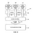
- FIG. 6is a functional block diagram that illustrates the relationship between protocol layers for both transmit and receive systems.
- FIG. 11is a functional block diagram of a DAB modulator.
- FIG. 13is a schematic representation of various transport frames used in the DAB system.
- FIG. 17is a schematic representation of another frame of data used in a DAB system.
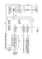
- FIG. 1is a functional block diagram of a transmitter 10 for use in a digital audio broadcasting system.
- the transmitterincludes an input 12 for receiving a main program service audio signal, an input 14 for receiving station identification service data, and an input 16 for receiving main program service data, supplemental program service data, and auxiliary application service data.
- the analog version of the main program service audio signalis delayed as shown by block 18 to produce a delayed analog audio signal on line 20 .
- An audio subsystem 22encodes and compresses the main program service audio signal to produce an encoded compressed digital signal on line 24 .
- the systememploys coding to reduce the sampled audio signal bit rate and baseband signal processing and to increase the robustness of the signal in the transmission channel. This allows a high quality audio signal plus ancillary data to be transmitted in band segments and at low levels which do not interfere with the existing analog signals.
- IBOC DAB signalscan be transmitted in a hybrid format including an analog modulated carrier in combination with a plurality of digitally modulated carriers or in an all-digital format wherein the analog modulated carrier is not used.
- Convolutional encodingcan be used. Convolutional encoding is a form of forward-error-correction channel encoding that inserts coding bits into a continuous stream of information bits to form a predictable structure. Unlike a block encoder, a convolutional encoder has memory, and its output is a function of current and previous inputs.
- the digital signalis transmitted in primary main sidebands on either side of the analog FM signal, as shown in FIG. 2 .
- Each primary main sidebandis comprised of ten frequency partitions, which are allocated among subcarriers 356 through 545, or ⁇ 356 through ⁇ 545.
- Subcarriers 546 and ⁇ 546, also included in the primary main sidebands,are additional reference subcarriers.
- the amplitude of each subcarriercan be scaled by an amplitude scale factor.
- Each secondary sidebandalso supports a small Secondary Protected (SP) region 90 , 92 including 12 OFDM subcarriers and reference subcarriers 279 and ⁇ 279.
- the sidebandsare referred to as “protected” because they are located in the area of spectrum least likely to be affected by analog or digital interference.
- An additional reference subcarrieris placed at the center of the channel (0). Frequency partition ordering of the SP region does not apply since the SP region does not contain frequency partitions.
- the AM and FM systemsshare a common system protocol stack, but differ primarily in the Layer 1 (L1) physical design.
- the upper layersare common to both the AM and FM systems.
- a control systemmanages the transfer and processing of the data streams from the application encoders.
- the following descriptionshows how information and data flow within the protocol stack from the perspective of both broadcast and receiver applications.
- FIG. 7is a functional block diagram of a portion of a transmitter showing components that perform the Layer 1 signal processing, including a scrambler 300 , a channel encoder 302 , an interleaver 304 , OFDM mapping 306 , OFDM signal generating 308 , a transmission subsystem 310 , and a system control processor 312 .
- the transmitter system control processor 312receives a system control signal on line 314 .
- the analog audio signal and SCA carriersare delivered to the transmission subsystem, on line 316 .
- the output signal from the RF Transmission Subsystemis then amplified by amplifier and matching circuit 318 and sent to an antenna 320 for broadcast.
- Scramblingrandomizes the digital data in each logical channel to “whiten” and mitigate signal periodicities when the waveform is demodulated in a conventional analog FM demodulator.
- the bits in each logical channelare scrambled to randomize the time-domain data and aid in receiver synchronization.
- the inputs to the scramblersare the active logical channels from the L1 SAP, as selected by the service mode.
- the outputs of the scramblersare transfer frames of scrambled bits for each of the active logical channels.
- the scramblergenerates a pseudorandom code which is modulo-2 summed with the input data vectors.
- the code generatoris a linear feedback shift register.
- Channel codingcomprises the functions of scrambling, channel encoding, and interleaving shown in FIG. 10 .
- Each logical channelis scrambled and encoded separately and in parallel. All parallel scramblers are identical, but operate at different rates, depending on the active service mode.
- Each scramblergenerates a maximal-length scrambling sequence using a linear feedback shift register with primitive polynomial.
- a given bit of a scrambled transfer frameis generated by modulo-2 adding the associated input bit with the corresponding bit of the scrambling sequence.
- FIG. 10is a functional block diagram of the signal constellation mapping 306 .
- a signal constellation mapper 346receives signals from a plurality of interleavers and produces signals that are scaled by scaler 348 and mapped to OFDM subcarriers by OFDM subcarrier mapper 350 .
- Interleavingis applied to the logical channels in the RF/Transmission subsystem. Interleaving comprises six parallel interleaving processes (IPs) designated as: PM, PX, SM, SX, SP, and SB.
- An IPcan contain one or more interleavers, and, in some cases, a transfer frame multiplexer.
- the service modedetermines which inputs and IPs are active at any given time.
- a P3IS control bit obtained from layer L2determines whether a long or short interleaver is employed.
- the universe of inputs for interleavingare the channel-encoded transfer frames from the primary logical channels P1 through P3 and PIDS, and the secondary logical channels S1 through S5 and SIDS.
- the interleaver outputsare matrices.
- the P3 logical channelmay utilize either a short or a long interleaver depth (time span).
- the long interleaver depthis more robust than the short interleaver depth.
- the long interleaver(about 1.48 seconds) results in a long decode time which affects receiver tuning time before audio can be heard. This long tuning time is unacceptable in some cases, so a short interleaver is used.
- Long or short interleaversare relative terms with regard to the PDU length.
- a short interleaverencapsulates an amount of bits of a single PDU, while a long interleaver can encapsulate bits from several consecutive PDUs.
- the length of the long interleaveris a parameter.
- robustness and content availability delayIf delay is considered, at a given time by a specific user for a specific case, to be the more important factor, then a short interleaver may be selected, resulting in limited robustness. If robustness is considered, under a given time and content combination, to be the more important factor, then a long interleaver may be selected.
- the system control channelbypasses the channel coding.
- System Control Processingassembles and differentially encodes a sequence of bits (system control data sequence) destined for each reference subcarrier.
- system control data sequencea sequence of bits (system control data sequence) destined for each reference subcarrier.
- OFDM Subcarrier Mappingassigns interleaver partitions to frequency partitions. For each active interleaver matrix, OFDM Subcarrier Mapping assigns a row of bits from each interleaver partition to its respective frequency partition in a complex output vector X. In addition, system control data sequence bits from a row of matrix R, the matrix of system control data sequences, are mapped to the active reference subcarrier locations in X. The service mode dictates which interleaver matrices and which elements of R are active.
- FIG. 10shows the inputs, output, and component functions of OFDM Subcarrier Mapping.
- the inputs to OFDM Subcarrier Mapping for each symbolare a row of bits from each active interleaver matrix and a row of bits from R, the matrix of system control data sequences.
- the output from OFDM Subcarrier Mapping for each OFDM symbolcan be a single complex vector, X, of length 1093.
- the interleaver matrices carrying the user audio and data(PM, PX1, . . . SB) are mapped to QPSK constellation points and to specific subcarriers.
- the R matrixis mapped to BPSK constellation points and the reference subcarriers.
- These phasorsare then scaled in amplitude and mapped to their assigned OFDM subcarriers. This process results in a vector, X, of phasors which are output to the OFDM signal generation function.
- the input to OFDM Signal Generation for the n th symbolis a complex vector X n of length L, representing the complex constellation values for each OFDM subcarrier in OFDM symbol n.
- the output of OFDM Subcarrier Mapping described abovedid not use the subscript n. Rather, it referred to the vector X as representing a single OFDM symbol.
- the subscriptis appended to X because of the significance of n to OFDM Signal Generation.
- the OFDM symbolis transformed to the time domain by a discreet Fourier transform and shaped to create one time domain symbol, y n (t).
- the output of OFDM Signal Generationis a complex, baseband, time-domain pulse y n (t), representing the digital portion of the FM IBOC signal for OFDM symbol n.
- FIG. 11is a functional block diagram of a DAB modulator.
- the plurality of OFDM signalsare supplied on line 352 and are subjected to concatenation as shown in block 354 .
- the concatenated signalsare upconverted as shown in block 356 to produce the plurality of digitally modulated subcarriers on line 358 .
- the analog program signalis supplied on line 360 and optional SCA subcarriers can be supplied on line 362 .
- the analog program signal and the optional SCA subcarriersare modulated by the analog FM modulator 364 .
- the modulated analog carrier, and SCA if present, and the digitally modulated subcarriersare combined in combiner 366 to produce the DAB waveform on line 368 .
- L2Layer 2
- FIG. 12is a functional block diagram that illustrates the relationship between protocol Layer 2 and higher protocol layers for both the transmit and receive systems.
- Service access points 400 , 402 and 404 in the transmitterreceive IBOC data service, main program and radio link signals.
- the signalsare processed as illustrated in IDS transport block 406 , MPA transport block 408 and RLS block 410 to produce IDS, MPA and RLS PDU's as illustrated by lines 412 , 413 and 414 .
- the transport functionsalso produce IDS, MPA and RLS SDU's, on lines 415 , 416 and 417 , which are delivered to service access point 418 of transmitter Layer 2.
- the transmitter Layer 2processes these signals as illustrated in block 0420 to produce Layer 2 PDU's, as illustrated by line 421 , which are transmitted to Layer 2 of the receiver and processed as shown in block 422 to produce SDU's that are sent to the higher protocol layers of the receiver through service access point 424 .
- IDS, MPA and RLS transport functions 426 , 428 and 430 in the higher layers of the receiverfurther process the signals to produce output signals at service data points 432 , 434 and 436 .
- a special transport/data linkcan be used for transmitting SIS data on PIDS and SIDS Layer 1 logical channels.
- Layer 2does not perform a multiplexing function, but rather just passes the transport PDUs directly into the Layer 1 PIDS or SIDS logical channel.
- the IDS transport PDUis the only PDU contained within the PIDS or SIDS Layer 1 logical channel.
- the PIDS and SIDS channelsare not multiplexed because SIS information must be transmitted in a known channel. This implies that the PIDS will not contain other types of transport information. In addition, the PIDS is too small to warrant the header bits required to allow for multiplexing.
- Layer 2allows these transports to be active within any active Layer 1 logical channel (with the exception of PIDS and SIDS).
- the structure of the Layer 2allows a transport that serves the multiplexing needs.
- An L2 PDUis equivalent to a Layer 1 (L1) PDU or transfer frame.
- Layer 1does not provide additional formatting or PCI information within its L1 PDU before it performs physical modem processing of the input L2 PDU.
- all PCI information added by Layer 1(designated as the system control data sequence) can be included in an independent channel dedicated to L1 PCI (the reference subcarriers) and would not require bandwidth from the Layer 1 payload.
- PCI information and synchronization informationare combined into one reference channel.
- the systemis extremely flexible and supports various configurations with respect to Layer 1. Based on the Layer 1 service mode, the system provides multiple Layer 1 logical channels. The number of active Layer 1 logical channels and the characteristics defining them vary for each service mode. The defining characteristics of each Layer 1 logical channel are:
- Layer 2is a slave to the Layer 1 service mode and configuration.
- the L2 PDU size and L2 PDU exchange rateare controlled by Layer 1.
- the total PDU size Layer 2delivers to the RLS and NPA PDU transports on the receive side is the Layer 1 frame size minus the L2 PCI overhead.
- FIG. 12illustrates Layer 2 processing from both transmit and receive perspectives.
- Layer 2requires the following operational parameters for each active Layer 1 logical channel (with the exception of PIDS and SIDS):
- Layer 1For each active Layer 1 logical channel, Layer 1 indicates to Layer 2 that it requires an L2 PDU. Based on the parameters defined above, L2 signals the MPA transport and/or the RLS to provide their respective PDU's (MPA Transport PDU, Fixed RLS PDU data) that are to be transmitted within the L2 PDU for that specific Layer 1 logical channel.
- MPA Transport PDUFixed RLS PDU data
- Layer 2When Layer 2 receives the NPA transport PDU, it determines if there is opportunistic bandwidth available. Opportunistic data is defined as the unused capacity of a Layer 1 channel in which a fixed allocation of bytes has been assigned to the MPA encoder but not fully utilized. This capacity is time-varying and is available for data transport. If so, Layer 2 indicates this to the RLS and the RLS provides an opportunistic RLS PDU to be included in the Layer 2 PDU.
- Layer 1For a PIDS or SIDS Layer 1 logical channel, Layer 1 indicates to Layer 2 that it requires a L2 PDU. Layer 2 indicates to the IDS Transport to provide its respective PDU. Layer 2 forwards the PIDS PDU directly to Layer 1.
- a receiverreceives an L2 PDU from L1 for each active logical channel, and extracts and decodes the L2 PCI Bits. Based on the L2 PCI, the receiver can route the entire L2 PDU to the appropriate destination, i.e. MPA Transport and or RLS (fixed and opportunistic).
- MPA Transportand or RLS (fixed and opportunistic).
- the receivercan route the received L2 PDU to the IDS Transport.
- the systemprovides SIS to all applications and services.
- the PIDS and SIDS logical channelsare dedicated to transporting SIS information that must be acquired quickly for scanning applications.
- IDS transportthat creates the PIDS/SIDS PDU for a PIDS/SIDS Layer 1 logical channel.
- Layer 2routes the PIDS and SIDS PDUs to Layer 1 directly.
- Layer 2routes the PIDS and SIDS PDUs to the IDS transport.
- PCIparses the payload.
- the headerprovides one of the following five indications corresponding to the PDU structures:
- FIG. 13schematically illustrates the five types of headers 440, 442, 444, 446 and 448.
- L2 PDU contentis audio-oriented (MPA Transport)
- opportunistic datacan still be inserted into the payload (Opp RLS), and additional signaling is provided by RLS such that the boundaries of the Opportunistic RLS PDU can be found and processed by the RLS.
- RLSadditional signaling
- the entire payloadis associated with the main program audio (MPA Transport) and is handled as such, due to signaling contained within the audio payload.
- MPA Transportmain program audio
- Such signalingenables the audio processing (NPA Transport) and RLS processing to use the payload properly.
- L2 PDUcontains a Fixed RLS PDU
- an extended header 444is deployed within the RLS.
- the mixed content PDUrequires additional indications.
- a delimiteris provided by RLS, indicating the payload parts associated with each type of service.
- the signalingis per transfer frame (PDU) and does not require any knowledge of previous or future transfer frames.
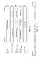
- a generic transfer frameas shown in FIG. 14 , includes the payload and the header PCI.
- the payload headerin one example consists of 24 bits, spread over the transfer frame.
- the headerincludes one of eight cyclic permutations, CW 0 through CW 7 , of a 24 bit sequence.
- the header sequences and the corresponding indication typeare described in Table 1.
- L2 on the transmit sideselects the appropriate sequence, based on the SCI obtained from the layers above.
- the contents of a selected CWare designated as [h 0 , h 1 , . . . , h 22 , h 23 ].
- the header lengthis 23 bits, h 23 is not used. If the header length is 22 bits, h 22 and h 23 are not used.
- the L2 PDUis received after being decoded by a Viterbi decoder at L1. Errors (if they occur) appear in bursts at the output of the decoder. Without spreading, a very small burst of L1 errors, that may corrupt an unspread sequence, may therefore prevent the use of a nearly perfect PDU. Spreading the sequence eliminates the problem.
- the headeris offset to avoid any damage that might occur if the preceding decoding at L1 is not optimal, resulting in errors on the edges of the PDU.
- the receiverupon receiving a transfer frame from L1, L2, processes the frame and determines the following,
- the IDS transport PDUis contained within either the PIDS or SIDS L1 channel frame.
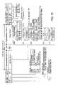
- the PIDS PDUis 80 bits in length as shown in FIG. 15 . The most significant bit of each field is shown on the left. Layer 2 and Layer 1 process bits MSB first—i.e. bit 0 is the first bit interleaved by L1.
- the PDU contentsare defined by several control fields within the PDU. The Type bit is normally set to zero. If this bit is a one, the remainder of the PDU contents may be different. This provides an option for future use.
- the PDU formatattempts to guarantee the ability to broadcast the advanced ALFN, while consuming negligible capacity, yet maintaining robustness.
- Some broadcastersmay want to send short call letters, while others may want to send long call letters. This system supports both. There is a tradeoff in that the long station names will take longer to be received and displayed to the user at the receiver. Each message serves a different target group and a different set of variables. Short content would use message 1, and long content would use both message 1 and message 2.
- ALFNincrements every L1 frame period coincident with the start of L1 block 0.
- the ALFN that is sentcorresponds to the actual frame number at the time it is broadcast over the air. If bit 65 of a PDU (regardless of MSG ID 1 or MSG ID 2) is set to one, the ALFN is locked to GPS time.
- the Station Location (MSG ID 0100) fieldindicates the absolute three-dimensional location of the feedpoint of the broadcast antenna. Such location information may be used by the receiver for position determination. Position information is split into two messages—a high and a low portion. Altitude is in units of (meters ⁇ 16) (i.e. the LSB is equal to 16 meters). Latitude and longitude are both in the same fractional formats. The LSB is equal to 1/8192 degrees. The MSB is the sign bit, which indicates the hemisphere. Positive longitude values represent positions north of the equator. Positive longitudes are in the eastern hemisphere. Longitude ranges are from ⁇ 180 to +180, while permissible latitude values are between ⁇ 90 and +90. Anything outside of these ranges is invalid. FIG. 16 shows the format of the station location information.
- Each PDUis terminated with a 12-bit cyclic redundancy check (CRC).
- CRCis computed based on all 68 bits of the other fields in the PDU, including unused message payload bits, which are always set to zero.
- the PIDS Transportallocates two bits to broadcast the absolute L1 frame number in a serial fashion.
- the formatis different for AM and FM as outlined in the following description. In both cases, the value of ALFN to be transmitted over the PIDS channel is updated coincident with L1 block 0 of each L1 frame.
- the 32 bitsare subdivided into two 16-bit groups, one labeled d16 through d31 (16 LSBs) and one labeled d0 through d15 (16 MSBs).
- ALFN bits d16:31are further subdivided into pairs and mapped to the two-bit Adv ALFN field of each PIDS block starting with block 0.
- ALFN bits d30:31are broadcast at block 0 of each frame, ALFN bits d28:29 are broadcast at block 1 of each frame and ALFN bits d16:17 are broadcast at block 7 of each frame.
- the processingsorts and sends, over time, the ALFN bits.
- the sorting methodconsumes negligible capacity, but allows the receiver to reliably recover and maintain the station ALFN, even when the PDU is impaired and the cyclic redundancy check (CRC) fails.
- CRCcyclic redundancy check
- ALFN bits d0:15are further subdivided into pairs and mapped to the Adv ALFN field in blocks 8 through 15 as shown.
- Layer 1 of the protocol stackdoes not handle ALFN directly, in regard to broadcasting the frame number.
- the frame numberis part of the PIDS logical channel, which is handled by L1.
- the relevant portion of the ALFN being sentapplies to the actual frame number at the time it is broadcast.
Landscapes
- Engineering & Computer Science (AREA)
- Signal Processing (AREA)
- Computer Networks & Wireless Communication (AREA)
- Multimedia (AREA)
- Physics & Mathematics (AREA)
- Spectroscopy & Molecular Physics (AREA)
- Power Engineering (AREA)
- Detection And Prevention Of Errors In Transmission (AREA)
- Circuits Of Receivers In General (AREA)
- Error Detection And Correction (AREA)
- Time-Division Multiplex Systems (AREA)
Abstract
Description
- 1. Main Program Service Audio Transport
- 2. Radio Link Service Transport
- 3. IDS Transport
Unused flags have been included to allow for additional transports in the future.
- Transfer Frame size
- Transfer Frame rate
- Robustness
- Latency
- A flag that indicates that each L2 PDU contains a Main Program Audio (MPA) Transport PDU
- A maximum size allocated for MPA transport PDU
- A flag that indicates that each L2 PDU contains Fixed RLS PDU(s)
- A maximum size allocated for RLS PDU(s)
- 1. Creating
Layer 2 PCI flags based on content and encoding - 2. Spreading
Layer 2 PCI flags across L2 PDU - 3. Inserting MPA and RLS PDUs into
Layer 2 PDU around the spread PCI
- 1. Creating
- The payload is audio oriented (MPA Transport PDU)
- The payload is data oriented (RLS Transport)
- A mixed content payload, containing MPA transport and opportunistic RLS transport PDUs
- A mixed content payload, containing MPA transport and fixed RLS transport PDUs
- A mixed content payload, containing MPA transport, opportunistic RLS transport, and fixed RLS PDUs
| TABLE 1 |
| Generic Header Sequence Indications |
| Fixed | Opp. | ||||
| Hexadecimal | MPA Transport | RLS | RLS | ||
| Sequence | Binary Header Sequence | Equivalent | PDU | PDU | PDU |
| CW0 | [110010110001101100011100] | 0xCB1B1C | Yes | No | No |
| CW1 | [001011000110110001110011] | 0x2C6C73 | Yes | No | Yes |
| CW2 | [001100101100011011000111] | 0x32C6C7 | Yes | Yes | No |
| CW3 | [110011001011000110110001] | 0xCCB1B1 | Yes | Yes | Yes |
| CW4 | [011100110010110001101100] | 0x732C6C | No | Yes | No |
| CW5 | [101100011100110010110001] | 0xB1CCB1 | Reserved | TBD | TBD |
| CW6 | [000111001100101100011011] | 0x1CCB1B | Reserved | TBD | TBD |
| CW7 | [110001110011001011000110] | 0xC732C6 | Reserved | TBD | TBD |
| TABLE 2 |
| Header Spread Parameters |
| L1 PDU | Header | |||
| Length, L | Nstart | Noffset | Length | |
| (Bits) | (L MOD 8) = | (Bits) | (Bits) | (Bits) |
| <72000 | 0 | 120 | INT[(L-Nstart)/24] − 1 | 24 |
| 7 | 120 | INT[(L-Nstart)/23] − 1 | 23 | |
| 1-6 | 120 | INT[(L-Nstart)/22] − 1 | 22 | |
| ≧72000 | 0 | L-30000 | INT[(L-Nstart)/24] − 1 | 24 |
| 7 | L-30000 | INT[(L-Nstart)/23] − 1 | 23 | |
| 1-6 | L-30000 | INT[(L-Nstart)/22] − 1 | 22 | |
- frame content
- boundaries of extended content, if such boundaries exist
- frame integrity management
- handling exceptions
Using the spread parameters for a given logical channel in a given L1 service mode, the L2 header bits are collected and put into a continuous 24 (or 22) bit structure, marked as Srcv. A correlation process of the received sequence with each possible expected sequence, can then take place.
Claims (48)
Priority Applications (13)
| Application Number | Priority Date | Filing Date | Title |
|---|---|---|---|
| US10/465,443US7305043B2 (en) | 2002-10-17 | 2003-06-19 | Method and apparatus for formatting signals for digital audio broadcasting transmission and reception |
| TW092128555ATWI282671B (en) | 2002-10-17 | 2003-10-15 | Method and apparatus for formatting signals for digital audio broadcasting transmission and reception |
| JP2005501448AJP4440209B2 (en) | 2002-10-17 | 2003-10-16 | Method and apparatus for formatting a signal for transmitting and receiving digital audio broadcasts |
| BR0315226-0ABR0315226A (en) | 2002-10-17 | 2003-10-16 | Digital audio broadcasting method, digital audio broadcasting transmitter, method for receiving a digital audio broadcasting signal, and receiver for receiving a digital audio broadcasting signal |
| RU2005114913/09ARU2321961C2 (en) | 2002-10-17 | 2003-10-16 | Method and device for formatting signals for transmitting and receiving digital audio radio broadcasting |
| EP03809103AEP1552630A4 (en) | 2002-10-17 | 2003-10-16 | Method and apparatus for formatting signals for digital audio broadcasting transmission and reception |
| PCT/US2003/032917WO2004036795A2 (en) | 2002-10-17 | 2003-10-16 | Method and apparatus for formatting signals for digital audio broadcasting transmission and reception |
| ARP030103770AAR041640A1 (en) | 2002-10-17 | 2003-10-16 | METHOD AND APPARATUS FOR FORMAT SIGNALS FOR DIGITAL AUDIO BROADCASTING AND RECEIVING |
| AU2003301494AAU2003301494B2 (en) | 2002-10-17 | 2003-10-16 | Method and apparatus for formatting signals for digital audio broadcasting transmission and reception |
| CN2003801015343ACN1706163B (en) | 2002-10-17 | 2003-10-16 | Method and apparatus for formatting signals for digital audio broadcasting transmission and reception |
| CA2500341ACA2500341C (en) | 2002-10-17 | 2003-10-16 | Method and apparatus for formatting signals for digital audio broadcasting transmission and reception |
| KR1020057006460AKR100955547B1 (en) | 2002-10-17 | 2003-10-16 | Digital audio broadcast transmission method, digital audio broadcast transmitter, digital audio broadcast reception method and receiver for receiving digital audio broadcast signal |
| MXPA05003465AMXPA05003465A (en) | 2002-10-17 | 2003-10-16 | Method and apparatus for formatting signals for digital audio broadcasting transmission and reception. |
Applications Claiming Priority (2)
| Application Number | Priority Date | Filing Date | Title |
|---|---|---|---|
| US41925902P | 2002-10-17 | 2002-10-17 | |
| US10/465,443US7305043B2 (en) | 2002-10-17 | 2003-06-19 | Method and apparatus for formatting signals for digital audio broadcasting transmission and reception |
Publications (2)
| Publication Number | Publication Date |
|---|---|
| US20040076188A1 US20040076188A1 (en) | 2004-04-22 |
| US7305043B2true US7305043B2 (en) | 2007-12-04 |
Family
ID=32096283
Family Applications (1)
| Application Number | Title | Priority Date | Filing Date |
|---|---|---|---|
| US10/465,443Expired - LifetimeUS7305043B2 (en) | 2002-10-17 | 2003-06-19 | Method and apparatus for formatting signals for digital audio broadcasting transmission and reception |
Country Status (13)
| Country | Link |
|---|---|
| US (1) | US7305043B2 (en) |
| EP (1) | EP1552630A4 (en) |
| JP (1) | JP4440209B2 (en) |
| KR (1) | KR100955547B1 (en) |
| CN (1) | CN1706163B (en) |
| AR (1) | AR041640A1 (en) |
| AU (1) | AU2003301494B2 (en) |
| BR (1) | BR0315226A (en) |
| CA (1) | CA2500341C (en) |
| MX (1) | MXPA05003465A (en) |
| RU (1) | RU2321961C2 (en) |
| TW (1) | TWI282671B (en) |
| WO (1) | WO2004036795A2 (en) |
Cited By (18)
| Publication number | Priority date | Publication date | Assignee | Title |
|---|---|---|---|---|
| US20060274715A1 (en)* | 2005-06-01 | 2006-12-07 | Hahm Mark D | Wireless terminal baseband processor high speed turbo decoding module supporting MAC header splitting |
| US20090157412A1 (en)* | 2007-12-18 | 2009-06-18 | Ibiquity Digital Corporation | Method For Streaming Through A Data Service Over A Radio Link Subsystem |
| US20090163137A1 (en)* | 2007-12-21 | 2009-06-25 | Ibiquity Digital Corporation | Systems and methods for communicating and rendering electronic program guide information via digital radio broadcast transmission |
| US20090259925A1 (en)* | 2008-04-10 | 2009-10-15 | Ibiquity Digital Corporation | Broadcast Equipment Communication Protocol |
| US20100265398A1 (en)* | 2009-04-15 | 2010-10-21 | Ibiquity Digital Corporation | Systems and methods for transmitting media content via digital radio broadcast transmission for synchronized rendering by a receiver |
| WO2011044349A1 (en)* | 2009-10-07 | 2011-04-14 | Ibiquity Digital Corporation | Systems and methods for transmitting media content via digital radio broadcast transmission for synchronized rendering by a receiver |
| US20110090897A1 (en)* | 2009-04-15 | 2011-04-21 | Ibiquity Digital Corporation | Systems and methods for transmitting media content via digital radio broadcast transmission for synchronized rendering by a receiver |
| US20110110283A1 (en)* | 2009-11-06 | 2011-05-12 | Yuh-Ren Tsai | Transmitter, receiver, multi-class multimedia broadcast/multicast service system and modulation method thereof |
| US8595748B1 (en) | 2007-12-21 | 2013-11-26 | Ibiquity Digital Corporation | Systems and methods for transmitting and receiving large objects via digital radio broadcast |
| US8660128B2 (en) | 2009-04-15 | 2014-02-25 | Ibiquity Digital Corporation | Systems and methods for a multiport synchronous-asynchronous client for scheduling and delivering content for digital radio broadcast transmission |
| US20140085098A1 (en)* | 2011-05-27 | 2014-03-27 | Halliburton Energy Services, Inc. | Downhole communication applications |
| US8792594B2 (en) | 2012-12-03 | 2014-07-29 | Digital PowerRadio, LLC | Systems and methods for advanced iterative decoding and channel estimation of concatenated coding systems |
| US9136874B2 (en) | 2013-03-15 | 2015-09-15 | Ibiquity Digital Corporation | Method and apparatus for transmission and reception of in-band on-channel radio signals including complementary low density parity check coding |
| US9778389B2 (en) | 2011-05-27 | 2017-10-03 | Halliburton Energy Services, Inc. | Communication applications |
| US9819480B2 (en) | 2015-08-04 | 2017-11-14 | Ibiquity Digital Corporation | System and method for synchronous processing of analog and digital pathways in a digital radio receiver |
| US10248496B2 (en) | 2013-05-03 | 2019-04-02 | Ibiquity Digital Corporation | Iterative forward error correction decoding for FM In-Band On-Channel radio broadcasting systems |
| US20190349132A1 (en)* | 2018-05-08 | 2019-11-14 | Ibiquity Digital Corporation | Lumb service modes for fm hd radio broadcasts |
| US12341712B2 (en) | 2004-05-01 | 2025-06-24 | Intellectual Ventures Ii Llc | Methods and apparatus for multi-carrier communications with variable channel bandwidth |
Families Citing this family (29)
| Publication number | Priority date | Publication date | Assignee | Title |
|---|---|---|---|---|
| US7305043B2 (en) | 2002-10-17 | 2007-12-04 | Ibiquity Digital Corporation | Method and apparatus for formatting signals for digital audio broadcasting transmission and reception |
| FR2855685B1 (en)* | 2003-05-27 | 2007-08-31 | Telediffusion De France Tdf | METHOD AND BROADCAST TRANSMITTER EMPLOYING PRE-FILTERING AND CORRESPONDING SIGNAL |
| US7474707B2 (en) | 2004-09-09 | 2009-01-06 | Ibiquity Digital Corporation | Bandwidth reduction of an FM broadcast signal using a baseband precompensation technique |
| CN101116274B (en)* | 2004-12-27 | 2011-07-06 | Lg电子株式会社 | Method for Sending Feedback Information Using Extended Subheader |
| US8027419B2 (en)* | 2005-04-08 | 2011-09-27 | Ibiquity Digital Corporation | Method for alignment of analog and digital audio in a hybrid radio waveform |
| CN100531398C (en)* | 2006-08-23 | 2009-08-19 | 中兴通讯股份有限公司 | Method for realizing multiple audio tracks in mobile multimedia broadcast system |
| CN1964485B (en)* | 2006-09-05 | 2012-05-09 | 中兴通讯股份有限公司 | Method for quickly playing multimedia broadcast channel |
| US8041292B2 (en)* | 2006-12-04 | 2011-10-18 | Ibiquity Digital Corporation | Network radio receiver |
| US8346230B2 (en)* | 2007-03-06 | 2013-01-01 | Capitol Broadcasting Company, Inc. | System and method for delivering geographically restricted content, such as over-air broadcast programming, to a recipient over a network, namely the internet |
| US8555148B2 (en)* | 2007-09-18 | 2013-10-08 | Samsung Electronics Co., Ltd. | Methods and apparatus to generate multiple CRCs |
| KR20090050994A (en) | 2007-11-16 | 2009-05-20 | 엘지전자 주식회사 | Digital broadcasting system and data processing method |
| US8521079B2 (en)* | 2007-12-21 | 2013-08-27 | Ibiquity Digital Corporation | Radio service registry |
| US20090165032A1 (en)* | 2007-12-21 | 2009-06-25 | Ibiquity Digital Corporation | Method And Apparatus For Managing Broadcasting Services Using Broadcast Tokens |
| US8111716B2 (en)* | 2008-02-15 | 2012-02-07 | Ibiquity Digital Corporation | Method and apparatus for formatting data signals in a digital audio broadcasting system |
| ES2431337T3 (en)* | 2008-06-04 | 2013-11-26 | Sony Corporation | New frame structure for multiple carrier systems |
| WO2011035328A1 (en)* | 2009-09-21 | 2011-03-24 | Jesse Caulfield | Improved operation of a cognitive radio resource coordinator |
| RU2557164C2 (en) | 2009-10-01 | 2015-07-20 | Интердиджитал Пэйтент Холдингз, Инк. | Uplink control data transmission |
| KR101288548B1 (en)* | 2009-12-15 | 2013-07-22 | 한국전자통신연구원 | Interleaving apparatus for improving transmission efficiency and interleaving method thereof |
| KR101521001B1 (en) | 2010-01-08 | 2015-05-15 | 인터디지탈 패튼 홀딩스, 인크 | Channel state information transmission for multiple carriers |
| RU2441321C1 (en)* | 2010-07-26 | 2012-01-27 | Федеральное государственное унитарное предприятие "Главный радиочастотный центр" (ФГУП "ГРЧЦ") | Method of mobile narrow-band digital multimedia broadcasting |
| UA107771C2 (en)* | 2011-09-29 | 2015-02-10 | Dolby Int Ab | Prediction-based fm stereo radio noise reduction |
| US9219573B2 (en)* | 2013-03-15 | 2015-12-22 | Ibiquity Digital Corporation | System and method for recovering audio PDU transport elements in digital radio broadcast receiver |
| US10121483B2 (en) | 2013-11-27 | 2018-11-06 | Telefonaktiebolaget Lm Ericsson (Publ) | Hybrid RTP payload format |
| KR102197468B1 (en)* | 2014-10-29 | 2020-12-31 | 한국전자통신연구원 | Method and apparatus for channel coding for fast advanced information processing in near field wireless communication |
| CN108123775B (en)* | 2016-11-29 | 2020-09-29 | 华为技术有限公司 | Method and device for transmitting data packets |
| US10878879B2 (en)* | 2017-06-21 | 2020-12-29 | Mediatek Inc. | Refresh control method for memory system to perform refresh action on all memory banks of the memory system within refresh window |
| US10484115B2 (en)* | 2018-02-09 | 2019-11-19 | Ibiquity Digital Corporation | Analog and digital audio alignment in the HD radio exciter engine (exgine) |
| CN113489568B (en) | 2018-02-14 | 2022-05-13 | 华为技术有限公司 | Method and device for transmitting audio data at high speed |
| CN110138695A (en)* | 2019-05-13 | 2019-08-16 | 深圳市华星光电技术有限公司 | Data scrambling method, de-scrambling method, relevant apparatus and storage medium |
Citations (5)
| Publication number | Priority date | Publication date | Assignee | Title |
|---|---|---|---|---|
| US6075789A (en) | 1995-07-06 | 2000-06-13 | Nokia Telecommunications Oy | System for connecting a packet data network to a digital radio network |
| US6188717B1 (en) | 1996-11-19 | 2001-02-13 | Deutsche Forschungsanstalt Fur Luft-Und Raumfahrt E.V. | Method of simultaneous radio transmission of digital data between a plurality of subscriber stations and a base station |
| US6289000B1 (en) | 2000-05-19 | 2001-09-11 | Intellon Corporation | Frame control encoder/decoder for robust OFDM frame transmissions |
| US20030092376A1 (en)* | 2001-10-26 | 2003-05-15 | Majid Syed | System and method for a push-pull gateway-directed digital receiver |
| US6788690B2 (en)* | 2002-06-27 | 2004-09-07 | Nokia Corporation | Packet identifier search filtering |
Family Cites Families (22)
| Publication number | Priority date | Publication date | Assignee | Title |
|---|---|---|---|---|
| US5315583A (en)* | 1991-04-11 | 1994-05-24 | Usa Digital Radio | Method and apparatus for digital audio broadcasting and reception |
| US5278844A (en)* | 1991-04-11 | 1994-01-11 | Usa Digital Radio | Method and apparatus for digital audio broadcasting and reception |
| US5278826A (en)* | 1991-04-11 | 1994-01-11 | Usa Digital Radio | Method and apparatus for digital audio broadcasting and reception |
| RU2019041C1 (en)* | 1991-04-26 | 1994-08-30 | Борис Иванович Волков | System of digital stereo broadcasting |
| RU2048704C1 (en)* | 1992-09-07 | 1995-11-20 | Борис Иванович Волков | Digital radio broadcasting system |
| US5465396A (en)* | 1993-01-12 | 1995-11-07 | Usa Digital Radio Partners, L.P. | In-band on-channel digital broadcasting |
| US5588022A (en)* | 1994-03-07 | 1996-12-24 | Xetron Corp. | Method and apparatus for AM compatible digital broadcasting |
| FI105754B (en)* | 1995-06-12 | 2000-09-29 | Nokia Oy Ab | Transfer protocol for transferring files on the DAB system |
| US5949796A (en)* | 1996-06-19 | 1999-09-07 | Kumar; Derek D. | In-band on-channel digital broadcasting method and system |
| JP3604264B2 (en)* | 1997-10-06 | 2004-12-22 | 株式会社東芝 | Caller terminal device, network system, and call information monitoring method |
| US6201798B1 (en)* | 1997-11-14 | 2001-03-13 | Worldspace Management Corporation | Signaling protocol for satellite direct radio broadcast system |
| US6134243A (en)* | 1998-01-15 | 2000-10-17 | Apple Computer, Inc. | Method and apparatus for media data transmission |
| US6108810A (en)* | 1998-03-27 | 2000-08-22 | Usa Digital Radio, Inc. | Digital audio broadcasting method using puncturable convolutional code |
| US6243424B1 (en)* | 1998-03-27 | 2001-06-05 | Ibiguity Digital Corporation | Method and apparatus for AM digital broadcasting |
| US6148007A (en)* | 1998-03-27 | 2000-11-14 | Usa Digital Radio Partners, L.P. | Method for data transmission in a digital audio broadcasting system |
| US6357029B1 (en)* | 1999-01-27 | 2002-03-12 | Agere Systems Guardian Corp. | Joint multiple program error concealment for digital audio broadcasting and other applications |
| US6556639B1 (en)* | 1999-06-24 | 2003-04-29 | Ibiquity Digital Corporation | Method and apparatus for determining transmission mode and synchronization for a digital audio broadcasting signal |
| US6549544B1 (en)* | 1999-11-10 | 2003-04-15 | Ibiquity Digital Corporation | Method and apparatus for transmission and reception of FM in-band on-channel digital audio broadcasting |
| US6587826B1 (en)* | 1999-12-15 | 2003-07-01 | Agere Systems Inc. | Channel code configurations for digital audio broadcasting systems and other types of communication systems |
| JP4240184B2 (en)* | 2000-11-06 | 2009-03-18 | ソニー株式会社 | Digital audio broadcast receiver |
| US20020144209A1 (en)* | 2001-02-20 | 2002-10-03 | Cute Ltd. | System for enhanced error correction in trellis decoding |
| US7305043B2 (en) | 2002-10-17 | 2007-12-04 | Ibiquity Digital Corporation | Method and apparatus for formatting signals for digital audio broadcasting transmission and reception |
- 2003
- 2003-06-19USUS10/465,443patent/US7305043B2/ennot_activeExpired - Lifetime
- 2003-10-15TWTW092128555Apatent/TWI282671B/ennot_activeIP Right Cessation
- 2003-10-16CACA2500341Apatent/CA2500341C/ennot_activeExpired - Lifetime
- 2003-10-16KRKR1020057006460Apatent/KR100955547B1/ennot_activeExpired - Lifetime
- 2003-10-16ARARP030103770Apatent/AR041640A1/enunknown
- 2003-10-16RURU2005114913/09Apatent/RU2321961C2/enactive
- 2003-10-16AUAU2003301494Apatent/AU2003301494B2/ennot_activeCeased
- 2003-10-16CNCN2003801015343Apatent/CN1706163B/ennot_activeExpired - Fee Related
- 2003-10-16JPJP2005501448Apatent/JP4440209B2/ennot_activeExpired - Lifetime
- 2003-10-16BRBR0315226-0Apatent/BR0315226A/ennot_activeApplication Discontinuation
- 2003-10-16EPEP03809103Apatent/EP1552630A4/ennot_activeWithdrawn
- 2003-10-16MXMXPA05003465Apatent/MXPA05003465A/enactiveIP Right Grant
- 2003-10-16WOPCT/US2003/032917patent/WO2004036795A2/enactiveSearch and Examination
Patent Citations (5)
| Publication number | Priority date | Publication date | Assignee | Title |
|---|---|---|---|---|
| US6075789A (en) | 1995-07-06 | 2000-06-13 | Nokia Telecommunications Oy | System for connecting a packet data network to a digital radio network |
| US6188717B1 (en) | 1996-11-19 | 2001-02-13 | Deutsche Forschungsanstalt Fur Luft-Und Raumfahrt E.V. | Method of simultaneous radio transmission of digital data between a plurality of subscriber stations and a base station |
| US6289000B1 (en) | 2000-05-19 | 2001-09-11 | Intellon Corporation | Frame control encoder/decoder for robust OFDM frame transmissions |
| US20030092376A1 (en)* | 2001-10-26 | 2003-05-15 | Majid Syed | System and method for a push-pull gateway-directed digital receiver |
| US6788690B2 (en)* | 2002-06-27 | 2004-09-07 | Nokia Corporation | Packet identifier search filtering |
Non-Patent Citations (1)
| Title |
|---|
| U.S. Appl. No. 09/382,716, filed Aug. 24, 1999, Kroeger et al. |
Cited By (36)
| Publication number | Priority date | Publication date | Assignee | Title |
|---|---|---|---|---|
| US12341712B2 (en) | 2004-05-01 | 2025-06-24 | Intellectual Ventures Ii Llc | Methods and apparatus for multi-carrier communications with variable channel bandwidth |
| US7532638B2 (en)* | 2005-06-01 | 2009-05-12 | Broadcom Corporation | Wireless terminal baseband processor high speed turbo decoding module supporting MAC header splitting |
| US20060274715A1 (en)* | 2005-06-01 | 2006-12-07 | Hahm Mark D | Wireless terminal baseband processor high speed turbo decoding module supporting MAC header splitting |
| US20090157412A1 (en)* | 2007-12-18 | 2009-06-18 | Ibiquity Digital Corporation | Method For Streaming Through A Data Service Over A Radio Link Subsystem |
| US9872066B2 (en) | 2007-12-18 | 2018-01-16 | Ibiquity Digital Corporation | Method for streaming through a data service over a radio link subsystem |
| US8595748B1 (en) | 2007-12-21 | 2013-11-26 | Ibiquity Digital Corporation | Systems and methods for transmitting and receiving large objects via digital radio broadcast |
| US20090163137A1 (en)* | 2007-12-21 | 2009-06-25 | Ibiquity Digital Corporation | Systems and methods for communicating and rendering electronic program guide information via digital radio broadcast transmission |
| US9350471B1 (en) | 2007-12-21 | 2016-05-24 | Ibiquity Digital Corporation | Systems and methods for transmitting and receiving large objects via digital radio broadcast |
| US8983365B2 (en) | 2007-12-21 | 2015-03-17 | Ibiquity Digital Corporation | Systems and methods for communicating and rendering electronic program guide information via digital radio broadcast transmission |
| US20090259925A1 (en)* | 2008-04-10 | 2009-10-15 | Ibiquity Digital Corporation | Broadcast Equipment Communication Protocol |
| US9118430B2 (en) | 2008-04-10 | 2015-08-25 | Ibiquity Digital Corporation | Broadcast equipment communication protocol |
| US8144612B2 (en) | 2009-04-15 | 2012-03-27 | Ibiquity Digital Corporation | Systems and methods for transmitting media content via digital radio broadcast transmission for synchronized rendering by a receiver |
| US8451868B2 (en) | 2009-04-15 | 2013-05-28 | Ibiquity Digital Corporation | Systems and methods for transmitting media content via digital radio broadcast transmission for synchronized rendering by a receiver |
| US8660128B2 (en) | 2009-04-15 | 2014-02-25 | Ibiquity Digital Corporation | Systems and methods for a multiport synchronous-asynchronous client for scheduling and delivering content for digital radio broadcast transmission |
| US20100265398A1 (en)* | 2009-04-15 | 2010-10-21 | Ibiquity Digital Corporation | Systems and methods for transmitting media content via digital radio broadcast transmission for synchronized rendering by a receiver |
| US8804037B2 (en) | 2009-04-15 | 2014-08-12 | Ibiquity Digital Corporation | Systems and methods for transmitting media content via digital radio broadcast transmission for synchronized rendering by a receiver |
| US20110090897A1 (en)* | 2009-04-15 | 2011-04-21 | Ibiquity Digital Corporation | Systems and methods for transmitting media content via digital radio broadcast transmission for synchronized rendering by a receiver |
| WO2011044349A1 (en)* | 2009-10-07 | 2011-04-14 | Ibiquity Digital Corporation | Systems and methods for transmitting media content via digital radio broadcast transmission for synchronized rendering by a receiver |
| US20110110283A1 (en)* | 2009-11-06 | 2011-05-12 | Yuh-Ren Tsai | Transmitter, receiver, multi-class multimedia broadcast/multicast service system and modulation method thereof |
| US8300568B2 (en)* | 2009-11-06 | 2012-10-30 | National Tsing Hua University | Transmitter, receiver, multi-class multimedia broadcast/multicast service system and modulation method thereof |
| US9625603B2 (en)* | 2011-05-27 | 2017-04-18 | Halliburton Energy Services, Inc. | Downhole communication applications |
| US20140085098A1 (en)* | 2011-05-27 | 2014-03-27 | Halliburton Energy Services, Inc. | Downhole communication applications |
| US9778389B2 (en) | 2011-05-27 | 2017-10-03 | Halliburton Energy Services, Inc. | Communication applications |
| US9455861B2 (en) | 2012-12-03 | 2016-09-27 | Ln2 Db, Llc | Systems and methods for advanced iterative decoding and channel estimation of concatenated coding systems |
| US9461863B2 (en) | 2012-12-03 | 2016-10-04 | Ln2 Db, Llc | Systems and methods for advanced iterative decoding and channel estimation of concatenated coding systems |
| US9391643B2 (en) | 2012-12-03 | 2016-07-12 | Digital PowerRadio, LLC | Systems and methods for advanced iterative decoding and channel estimation of concatenated coding systems |
| US9838154B2 (en) | 2012-12-03 | 2017-12-05 | Ln2 Db, Llc | Systems and methods for advanced iterative decoding and channel estimation of concatenated coding systems |
| US8792594B2 (en) | 2012-12-03 | 2014-07-29 | Digital PowerRadio, LLC | Systems and methods for advanced iterative decoding and channel estimation of concatenated coding systems |
| US10135567B2 (en) | 2012-12-03 | 2018-11-20 | Ln2 Db, Llc | Systems and methods for advanced iterative decoding and channel estimation of concatenated coding systems |
| US9191256B2 (en) | 2012-12-03 | 2015-11-17 | Digital PowerRadio, LLC | Systems and methods for advanced iterative decoding and channel estimation of concatenated coding systems |
| US9479197B2 (en) | 2013-03-15 | 2016-10-25 | Ibiquity Digital Corporation | Method and apparatus for transmission and reception of in-band on-channel radio signals including complementary low density parity check coding |
| US9136874B2 (en) | 2013-03-15 | 2015-09-15 | Ibiquity Digital Corporation | Method and apparatus for transmission and reception of in-band on-channel radio signals including complementary low density parity check coding |
| US10248496B2 (en) | 2013-05-03 | 2019-04-02 | Ibiquity Digital Corporation | Iterative forward error correction decoding for FM In-Band On-Channel radio broadcasting systems |
| US9819480B2 (en) | 2015-08-04 | 2017-11-14 | Ibiquity Digital Corporation | System and method for synchronous processing of analog and digital pathways in a digital radio receiver |
| US20190349132A1 (en)* | 2018-05-08 | 2019-11-14 | Ibiquity Digital Corporation | Lumb service modes for fm hd radio broadcasts |
| US10727980B2 (en)* | 2018-05-08 | 2020-07-28 | Ibiquity Digital Corporation | Lumb service modes for FM HD radio broadcasts |
Also Published As
| Publication number | Publication date |
|---|---|
| WO2004036795A3 (en) | 2004-08-05 |
| US20040076188A1 (en) | 2004-04-22 |
| KR20050070055A (en) | 2005-07-05 |
| KR100955547B1 (en) | 2010-04-30 |
| AU2003301494A1 (en) | 2004-05-04 |
| CA2500341C (en) | 2011-01-04 |
| WO2004036795A2 (en) | 2004-04-29 |
| EP1552630A4 (en) | 2010-11-03 |
| MXPA05003465A (en) | 2005-09-30 |
| CA2500341A1 (en) | 2004-04-29 |
| RU2005114913A (en) | 2005-11-10 |
| RU2321961C2 (en) | 2008-04-10 |
| JP2006503523A (en) | 2006-01-26 |
| TW200421764A (en) | 2004-10-16 |
| CN1706163A (en) | 2005-12-07 |
| EP1552630A2 (en) | 2005-07-13 |
| TWI282671B (en) | 2007-06-11 |
| CN1706163B (en) | 2010-07-14 |
| BR0315226A (en) | 2005-08-23 |
| AU2003301494B2 (en) | 2008-10-23 |
| AR041640A1 (en) | 2005-05-26 |
| JP4440209B2 (en) | 2010-03-24 |
Similar Documents
| Publication | Publication Date | Title |
|---|---|---|
| US7305043B2 (en) | Method and apparatus for formatting signals for digital audio broadcasting transmission and reception | |
| US7352817B2 (en) | Method and apparatus for interleaving signal bits in a digital audio broadcasting system | |
| US8111716B2 (en) | Method and apparatus for formatting data signals in a digital audio broadcasting system | |
| CN113395136B (en) | Broadcast transmitter, broadcast receiver and method for processing broadcast signal | |
| RU2251812C2 (en) | Method and device for transmitting and receiving compressed sound signal frames with priority messages for digital sound broadcasting | |
| JP4527864B2 (en) | Digital signal transmission / reception method in digital audio broadcasting (DAB) system | |
| CA2910573C (en) | Iterative forward error correction decoding for fm in-band on-channel radio broadcasting systems | |
| JP6333983B2 (en) | Method and apparatus for transmitting and receiving broadcast signals including a robust header compressed packet stream | |
| CN112491770A (en) | Broadcast signal transmitting and receiving apparatus and method | |
| US10727980B2 (en) | Lumb service modes for FM HD radio broadcasts | |
| US6307890B1 (en) | High density FM subcarrier modulation with standardized network layer |
Legal Events
| Date | Code | Title | Description |
|---|---|---|---|
| AS | Assignment | Owner name:IBIQUITY DIGITAL CORPORATION, MARYLAND Free format text:ASSIGNMENT OF ASSIGNORS INTEREST;ASSIGNORS:MILBAR, MAREK;STEKAS, JAMES C.;REEL/FRAME:014073/0697 Effective date:20030616 Owner name:IBIQUITY DIGITAL CORPORATION, MARYLAND Free format text:ASSIGNMENT OF ASSIGNORS INTEREST;ASSIGNORS:MILBAR, MAREK;STEKAS, JAMES C.;REEL/FRAME:014209/0047 Effective date:20030616 | |
| AS | Assignment | Owner name:IBIQUITY DIGITAL CORPORATION, MARYLAND Free format text:ASSIGNMENT OF ASSIGNORS INTEREST;ASSIGNORS:MILBAR, MAREK;STEKAS, JAMES C.;REEL/FRAME:014077/0691 Effective date:20030616 | |
| AS | Assignment | Owner name:COLUMBIA PARTNERS, L.L.C. INVESTMENT MANAGEMENT, D Free format text:INTELLECTUAL PROPERTY SECURITY AGMT.;ASSIGNOR:IBIQUITY DIGITAL CORPORAION;REEL/FRAME:015780/0545 Effective date:20050208 Owner name:COLUMBIA PARTNERS, L.L.C. INVESTMENT MANAGEMENT,DI Free format text:INTELLECTUAL PROPERTY SECURITY AGMT;ASSIGNOR:IBIQUITY DIGITAL CORPORAION;REEL/FRAME:015780/0545 Effective date:20050208 | |
| AS | Assignment | Owner name:IBIQUITY DIGITAL CORPORATION,MARYLAND Free format text:TERMINATION OF PATENT SECURITY INTEREST;ASSIGNOR:COLUMBIA PARTNERS, L.L.C. INVESTMENT MANAGEMENT, AS INVESTMENT MANAGER AND AGENT FOR LENDER;REEL/FRAME:018573/0111 Effective date:20061130 Owner name:IBIQUITY DIGITAL CORPORATION, MARYLAND Free format text:TERMINATION OF PATENT SECURITY INTEREST;ASSIGNOR:COLUMBIA PARTNERS, L.L.C. INVESTMENT MANAGEMENT, AS INVESTMENT MANAGER AND AGENT FOR LENDER;REEL/FRAME:018573/0111 Effective date:20061130 | |
| AS | Assignment | Owner name:MERRILL LYNCH CREDIT PRODUCTS, LLC, AS ADMINISTRAT Free format text:PATENT SECURITY AGREEMENT;ASSIGNOR:IBIQUITY DIGITAL CORPORATION;REEL/FRAME:018606/0578 Effective date:20061201 | |
| STCF | Information on status: patent grant | Free format text:PATENTED CASE | |
| AS | Assignment | Owner name:MERRILL LYNCH CREDIT PRODUCTS, LLC, AS COLLATERAL Free format text:PATENT SECURITY AGREEMENT SUPPLEMENT;ASSIGNOR:IBIQUITY DIGITAL CORPORATION;REEL/FRAME:020593/0215 Effective date:20080303 | |
| CC | Certificate of correction | ||
| AS | Assignment | Owner name:MERRILL LYNCH CREDIT PRODUCTS, LLC, AS COLLATERAL Free format text:CORRECTIVE ASSIGNMENT TO CORRECT THE PATENT APPLICATION INADVERTENTLY RECORDED IN THIS DOCUMENT. 12/033,323 SHOULD NOT HAVE BEEN RECORDED IN THIS DOCUMENT, PREVIOUSLY RECORDED ON REEL 020593 FRAME 0215;ASSIGNOR:IBIQUITYDIGITAL CORPORATION;REEL/FRAME:022951/0789 Effective date:20080303 Owner name:MERRILL LYNCH CREDIT PRODUCTS, LLC, AS COLLATERAL Free format text:CORRECTIVE ASSIGNMENT TO CORRECT THE PATENT APPLICATION INADVERTENTLY RECORDED IN THIS DOCUMENT. 12/033,323 SHOULD NOT HAVE BEEN RECORDED IN THIS DOCUMENT, PREVIOUSLY RECORDED ON REEL 020593 FRAME 0215. ASSIGNOR(S) HEREBY CONFIRMS THE PATENT SECURITY AGREEMENT SUPPLEMENT.;ASSIGNOR:IBIQUITYDIGITAL CORPORATION;REEL/FRAME:022951/0789 Effective date:20080303 | |
| AS | Assignment | Owner name:MERRILL LYNCH CREDIT PRODUCTS, LLC, AS COLLATERAL Free format text:CORRECTIVE ASSIGNMENT TO CORRECT THE PATENT APPLICATION, 12/033,323,WHICH WAS INADVERTENTLY INCLUDED IN THIS DOCUMENT, SN SHOULD NOT BE ICLUDED IN DOCUMENT, PREVIOUSLY RECORDED ON REEL 020593 FRAME 215.;ASSIGNOR:IBIQUITY DIGITAL CORPORATION;REEL/FRAME:023003/0124 Effective date:20080303 Owner name:MERRILL LYNCH CREDIT PRODUCTS, LLC, AS COLLATERAL Free format text:CORRECTIVE ASSIGNMENT TO CORRECT THE PATENT APPLICATION, 12/033,323,WHICH WAS INADVERTENTLY INCLUDED IN THIS DOCUMENT, SN SHOULD NOT BE ICLUDED IN DOCUMENT, PREVIOUSLY RECORDED ON REEL 020593 FRAME 215. ASSIGNOR(S) HEREBY CONFIRMS THE PATENT SECURITY AGREEMENT SUPPLEMENT.;ASSIGNOR:IBIQUITY DIGITAL CORPORATION;REEL/FRAME:023003/0124 Effective date:20080303 | |
| FPAY | Fee payment | Year of fee payment:4 | |
| FPAY | Fee payment | Year of fee payment:8 | |
| AS | Assignment | Owner name:IBIQUITY DIGITAL CORPORATION, MARYLAND Free format text:RELEASE BY SECURED PARTY;ASSIGNOR:MERRILL LYNCH CREDIT PRODUCTS, LLC;REEL/FRAME:036877/0146 Effective date:20151001 | |
| AS | Assignment | Owner name:WELLS FARGO BANK, NATIONAL ASSOCIATION, AS ADMINIS Free format text:SECURITY INTEREST;ASSIGNOR:IBIQUITY DIGITAL CORPORATION;REEL/FRAME:037069/0153 Effective date:20151001 | |
| AS | Assignment | Owner name:ROYAL BANK OF CANADA, AS COLLATERAL AGENT, CANADA Free format text:SECURITY INTEREST;ASSIGNORS:INVENSAS CORPORATION;TESSERA, INC.;TESSERA ADVANCED TECHNOLOGIES, INC.;AND OTHERS;REEL/FRAME:040797/0001 Effective date:20161201 | |
| AS | Assignment | Owner name:IBIQUITY DIGITAL CORPORATION, MARYLAND Free format text:RELEASE BY SECURED PARTY;ASSIGNOR:WELLS FARGO BANK, NATIONAL ASSOCIATION;REEL/FRAME:040821/0108 Effective date:20161201 | |
| MAFP | Maintenance fee payment | Free format text:PAYMENT OF MAINTENANCE FEE, 12TH YEAR, LARGE ENTITY (ORIGINAL EVENT CODE: M1553); ENTITY STATUS OF PATENT OWNER: LARGE ENTITY Year of fee payment:12 | |
| AS | Assignment | Owner name:BANK OF AMERICA, N.A., NORTH CAROLINA Free format text:SECURITY INTEREST;ASSIGNORS:ROVI SOLUTIONS CORPORATION;ROVI TECHNOLOGIES CORPORATION;ROVI GUIDES, INC.;AND OTHERS;REEL/FRAME:053468/0001 Effective date:20200601 | |
| AS | Assignment | Owner name:INVENSAS BONDING TECHNOLOGIES, INC. (F/K/A ZIPTRONIX, INC.), CALIFORNIA Free format text:RELEASE BY SECURED PARTY;ASSIGNOR:ROYAL BANK OF CANADA;REEL/FRAME:052920/0001 Effective date:20200601 Owner name:INVENSAS CORPORATION, CALIFORNIA Free format text:RELEASE BY SECURED PARTY;ASSIGNOR:ROYAL BANK OF CANADA;REEL/FRAME:052920/0001 Effective date:20200601 Owner name:FOTONATION CORPORATION (F/K/A DIGITALOPTICS CORPORATION AND F/K/A DIGITALOPTICS CORPORATION MEMS), CALIFORNIA Free format text:RELEASE BY SECURED PARTY;ASSIGNOR:ROYAL BANK OF CANADA;REEL/FRAME:052920/0001 Effective date:20200601 Owner name:TESSERA, INC., CALIFORNIA Free format text:RELEASE BY SECURED PARTY;ASSIGNOR:ROYAL BANK OF CANADA;REEL/FRAME:052920/0001 Effective date:20200601 Owner name:DTS LLC, CALIFORNIA Free format text:RELEASE BY SECURED PARTY;ASSIGNOR:ROYAL BANK OF CANADA;REEL/FRAME:052920/0001 Effective date:20200601 Owner name:TESSERA ADVANCED TECHNOLOGIES, INC, CALIFORNIA Free format text:RELEASE BY SECURED PARTY;ASSIGNOR:ROYAL BANK OF CANADA;REEL/FRAME:052920/0001 Effective date:20200601 Owner name:PHORUS, INC., CALIFORNIA Free format text:RELEASE BY SECURED PARTY;ASSIGNOR:ROYAL BANK OF CANADA;REEL/FRAME:052920/0001 Effective date:20200601 Owner name:DTS, INC., CALIFORNIA Free format text:RELEASE BY SECURED PARTY;ASSIGNOR:ROYAL BANK OF CANADA;REEL/FRAME:052920/0001 Effective date:20200601 Owner name:IBIQUITY DIGITAL CORPORATION, MARYLAND Free format text:RELEASE BY SECURED PARTY;ASSIGNOR:ROYAL BANK OF CANADA;REEL/FRAME:052920/0001 Effective date:20200601 | |
| AS | Assignment | Owner name:IBIQUITY DIGITAL CORPORATION, CALIFORNIA Free format text:PARTIAL RELEASE OF SECURITY INTEREST IN PATENTS;ASSIGNOR:BANK OF AMERICA, N.A., AS COLLATERAL AGENT;REEL/FRAME:061786/0675 Effective date:20221025 Owner name:PHORUS, INC., CALIFORNIA Free format text:PARTIAL RELEASE OF SECURITY INTEREST IN PATENTS;ASSIGNOR:BANK OF AMERICA, N.A., AS COLLATERAL AGENT;REEL/FRAME:061786/0675 Effective date:20221025 Owner name:DTS, INC., CALIFORNIA Free format text:PARTIAL RELEASE OF SECURITY INTEREST IN PATENTS;ASSIGNOR:BANK OF AMERICA, N.A., AS COLLATERAL AGENT;REEL/FRAME:061786/0675 Effective date:20221025 Owner name:VEVEO LLC (F.K.A. VEVEO, INC.), CALIFORNIA Free format text:PARTIAL RELEASE OF SECURITY INTEREST IN PATENTS;ASSIGNOR:BANK OF AMERICA, N.A., AS COLLATERAL AGENT;REEL/FRAME:061786/0675 Effective date:20221025 |