US7304875B1 - Content addressable memory (CAM) devices that support background BIST and BISR operations and methods of operating same - Google Patents
Content addressable memory (CAM) devices that support background BIST and BISR operations and methods of operating sameDownload PDFInfo
- Publication number
- US7304875B1 US7304875B1US11/184,414US18441405AUS7304875B1US 7304875 B1US7304875 B1US 7304875B1US 18441405 AUS18441405 AUS 18441405AUS 7304875 B1US7304875 B1US 7304875B1
- Authority
- US
- United States
- Prior art keywords
- cam
- cam array
- array blocks
- operations
- error
- Prior art date
- Legal status (The legal status is an assumption and is not a legal conclusion. Google has not performed a legal analysis and makes no representation as to the accuracy of the status listed.)
- Expired - Lifetime, expires
Links
Images


Classifications
- G—PHYSICS
- G11—INFORMATION STORAGE
- G11C—STATIC STORES
- G11C15/00—Digital stores in which information comprising one or more characteristic parts is written into the store and in which information is read-out by searching for one or more of these characteristic parts, i.e. associative or content-addressed stores
- G—PHYSICS
- G06—COMPUTING OR CALCULATING; COUNTING
- G06F—ELECTRIC DIGITAL DATA PROCESSING
- G06F11/00—Error detection; Error correction; Monitoring
- G06F11/07—Responding to the occurrence of a fault, e.g. fault tolerance
- G06F11/08—Error detection or correction by redundancy in data representation, e.g. by using checking codes
- G06F11/10—Adding special bits or symbols to the coded information, e.g. parity check, casting out 9's or 11's
- G06F11/1008—Adding special bits or symbols to the coded information, e.g. parity check, casting out 9's or 11's in individual solid state devices
- G06F11/1064—Adding special bits or symbols to the coded information, e.g. parity check, casting out 9's or 11's in individual solid state devices in cache or content addressable memories
- G—PHYSICS
- G11—INFORMATION STORAGE
- G11C—STATIC STORES
- G11C29/00—Checking stores for correct operation ; Subsequent repair; Testing stores during standby or offline operation
- G11C29/04—Detection or location of defective memory elements, e.g. cell constructio details, timing of test signals
- G11C29/08—Functional testing, e.g. testing during refresh, power-on self testing [POST] or distributed testing
- G11C29/12—Built-in arrangements for testing, e.g. built-in self testing [BIST] or interconnection details
- G11C29/38—Response verification devices
- G11C29/42—Response verification devices using error correcting codes [ECC] or parity check
- G—PHYSICS
- G11—INFORMATION STORAGE
- G11C—STATIC STORES
- G11C29/00—Checking stores for correct operation ; Subsequent repair; Testing stores during standby or offline operation
- G11C29/04—Detection or location of defective memory elements, e.g. cell constructio details, timing of test signals
- G11C29/08—Functional testing, e.g. testing during refresh, power-on self testing [POST] or distributed testing
- G11C29/12—Built-in arrangements for testing, e.g. built-in self testing [BIST] or interconnection details
- G11C29/44—Indication or identification of errors, e.g. for repair
- G11C29/4401—Indication or identification of errors, e.g. for repair for self repair
- G—PHYSICS
- G11—INFORMATION STORAGE
- G11C—STATIC STORES
- G11C29/00—Checking stores for correct operation ; Subsequent repair; Testing stores during standby or offline operation
- G11C29/70—Masking faults in memories by using spares or by reconfiguring
- G11C29/78—Masking faults in memories by using spares or by reconfiguring using programmable devices
- G11C29/80—Masking faults in memories by using spares or by reconfiguring using programmable devices with improved layout
- G11C29/816—Masking faults in memories by using spares or by reconfiguring using programmable devices with improved layout for an application-specific layout
- G—PHYSICS
- G11—INFORMATION STORAGE
- G11C—STATIC STORES
- G11C29/00—Checking stores for correct operation ; Subsequent repair; Testing stores during standby or offline operation
- G11C29/04—Detection or location of defective memory elements, e.g. cell constructio details, timing of test signals
- G11C29/08—Functional testing, e.g. testing during refresh, power-on self testing [POST] or distributed testing
- G11C29/12—Built-in arrangements for testing, e.g. built-in self testing [BIST] or interconnection details
- G11C2029/1208—Error catch memory
Definitions
- the present inventionrelates to integrated circuit memory devices and, more particularly, to content addressable memory (CAM) devices and methods of operating same.
- CAMcontent addressable memory
- RAMrandom access memory
- datais typically accessed by supplying an address to an array of memory cells and then reading data from the memory cells that reside at the supplied address.
- datae.g., search words
- data within a CAM arrayis not accessed by initially supplying an address, but rather by initially applying data (e.g., search words) to the array and then performing a search operation to identify one or more entries within the CAM array that contain data equivalent to the applied data and thereby represent a “match” condition. In this manner, data is accessed according to its content rather than its address.
- the identified location(s) containing the equivalent datais typically encoded to provide an address (e.g., block address+row address within a block) at which the matching entry is located.
- an addresse.g., block address+row address within a block
- local priority encoding operationsmay be performed to identify a location of a best or highest priority matching entry. Such priority encoding operations frequently utilize the relative physical locations of multiple matching entries within the CAM array to identify a highest priority matching entry.
- An exemplary CAM device that utilizes a priority encoder to identify a highest priority matching entryis disclosed in commonly assigned U.S. Pat. No.
- CAM cellsare frequently configured as binary CAM cells that store only data bits (as “1” or “0” logic values) or as ternary (or quaternary) CAM cells that store data bits and mask bits.
- ternary CAM cellswhen a mask bit within a ternary CAM cell is inactive (e.g., set to a logic 1 value), the ternary CAM cell may operate as a conventional binary CAM cell storing an “unmasked” data bit.
- the ternary CAM cellWhen the mask bit is active (e.g., set to a logic 0 value), the ternary CAM cell is treated as storing a “don't care” (X) value, which means that all compare operations performed on the actively masked ternary CAM cell will result in a cell match condition.
- Xdon't care
- a compare operationwill yield one or more match conditions whenever all the unmasked data bits of an entry in the ternary CAM array are identical to the corresponding data bits of the applied search word.
- the applied search wordequals ⁇ 1011 ⁇
- the following entrieswill result in a match condition in a CAM comprising ternary CAM cells: ⁇ 1011 ⁇ , ⁇ X011 ⁇ , ⁇ 1X11 ⁇ , ⁇ 10X1 ⁇ , ⁇ 101X ⁇ , ⁇ XX11 ⁇ , ⁇ 1XX1 ⁇ , . . .
- CAM devicesmay also use coding techniques to detect and correct one-bit soft errors in entries within a CAM array.
- One such CAM device that uses a parity comparator to detect errorsis described in U.S. Pat. No. 6,067,656 to Rusu et al., entitled “Method and Apparatus for Detecting Soft Errors in Content Addressable Memory Arrays.”
- Another such CAM device that uses dynamic content addressable memory (DCAM) cellsis disclosed in U.S. Pat. No.
- U.S. Pat. No. 6,597,595 to Ichiriu et al.discloses a CAM device that performs error detection signaling operations. These error detection signaling operations are described as background error checking operations that consume little if any compare bandwidth. This is because any operation to read an entry from a CAM array for error checking purposes may be performed concurrently with the performance of compare operations on the same CAM array.
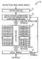
- FIG. 1which is a reproduction of FIG. 10 from the '595 patent, a CAM array 321 is provided with multiple storage blocks 325 (shown as Blocks 1 -K).
- parity-based error detectorIn response to a read operation from a check address 155 (CADDR) within the CAM array 321 , data, parity and validity values (shown as DPV 1 through DPV K ) are passed through a read/write circuit 322 into a parity-based error detector 323 .
- This parity-based error detectoris illustrated as including a plurality of error detection circuits 329 .
- This check address 155may be supplied by a check address generator (see, e.g., Block 124 in FIG. 2 of the '595 patent).
- Each of these error detection circuits 329performs a parity-based error detection operation on a corresponding data word and generates a respective block parity error signal 330 (BLOCK ERROR).
- These block parity error signals 330may be logically ORed by an OR gate 331 into a global parity error signal 335 (GLOBAL ERROR).
- the global parity error signal 335is provided as a load input to an error address register 337 and as a set input to an S-R flip-flop 339 .
- the resulting global parity error signal 335is used to load the check address 155 into the error address register 337 and to set the S-R flip-flop 339 .
- the S-R flip-flop 339can be reset by driving a reset signal 153 (RESET) high.
- the error address register 337is also illustrated as receiving a read signal 151 (READ) and a clock signal 104 (CLK).
- the error address register 337 and the S-R flip-flop 339are configured to output an error address 131 (ERROR ADDR) and an error flag (EFLAG) 132 .
- the error detector 323may also include circuitry (not shown) to store a value indicative of which of the error detection circuits has signaled a block error. This value, referred to as a block identifier, may be stored along with the check address 155 in the error address register 337 . The block identifier may then be output from the error address register 337 (as part of the error address) to thereby enable a host or other circuitry within the CAM device to identify the block or blocks within the CAM array 321 that produced the error indication.
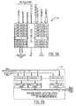
- FIG. 2which is a reproduction of FIG. 16 from the '595 patent, an alternative error detector 501 is illustrated.
- This error detector 501is an error detector/corrector that uses a more complex error correction code instead of parity bit(s).
- a CAM entryis illustrated as including a data word 503 , shown as data D[M-1,0], an error correction code word 505 (e.g., Hamming code word) and a validity bit 506 (V).
- This CAM entryresides at the error address 536 (EADDR) specified by an ECC address generator 535 .
- This error address 536may be provided to an address selector (see, e.g., Block 125 in FIG.
- the error correction code word 505in order to enable one bit error correction within a data word having a length of M bits, the error correction code word 505 should have a length equal to “c” bits, where the length “c” meets the following relationship: 2 c ⁇ M+c+1 ⁇ 2 c ⁇ 1 .
- the data word 503 and error correction code word 505are provided to a syndrome generator 507 , which generates a syndrome 508 (i.e., parity check vector).
- the bits of the syndrome 508are logically ORed using an OR gate 511 to generate a result signal that indicates whether an error is present in the CAM entry.
- An error correction circuit 509is also provided. The error correction circuit 509 receives the data word 503 and syndrome 508 . If the error represents a single bit error that can be corrected, then the error correction circuit 509 generates a C-bit signal 512 (C-BIT), which indicates whether a correction has taken place, and a corrected CAM word 510 (data word and error correction code word).
- C-BITC-bit signal
- the error address 536(EADDR), corrected CAM word 510 (CDATA), error signal 514 (E) and C-bit signal 512 (C) are stored within an error address register 517 , which is responsive to a clock signal 104 .
- the error signals 514 and error addresses 536 that are stored within the error address register 517may be used to generate an error flag 532 (EFLAG) and error address 531 (EADDR), which may be used to support background self-invalidation operations (see, e.g., FIG. 14 of the '595 patent).
- a write data multiplexer 540which is responsive to a path select signal 541 , is also provided so that a corrected CAM word (CDATA 0 -CDATA X ⁇ 1 ) may be written back into a CAM array at an address specified by the corresponding error address (EADDR 0 -EADDR X ⁇ 1 ).
- Search engine devicesinclude a content addressable memory (CAM) core having a plurality of CAM array blocks therein and a control circuit that is electrically coupled to the CAM core.
- the control circuitmay include, among other things, an instruction FIFO, instruction loading and execution logic and check bit generation and error correction logic.
- the instruction loading and execution logicmay perform instruction pipelining operations that eliminate the need for an instruction FIFO, or the instruction loading and execution logic may be configured to support no-op cycle generation even when the instruction FIFO is partially full.
- the control circuitis configured to support internal error detection and correction operations that can operate without significant impact on the compare bandwidth of the search engine device, even when operations to read entries from the CAM core are performed as foreground operations that may block concurrent search operations.
- the control circuitmay perform the error detection and correction operations by issuing multiple read instructions. These instructions include a first instruction (e.g., error check instruction) to read at least a first entry within the CAM core for the purpose of error detection and then, in response to detecting the first entry as erroneous, issuing a second instruction to read the first entry from the CAM core.
- a first instructione.g., error check instruction
- the first read operationmay be performed as a “high bandwidth” error checking operation that causes many CAM entries to be read in parallel from a plurality of CAM array blocks and checked in parallel for parity errors.
- the second read operation(or sequence of read operations) is a much more selective operation because it is directed at only those entries that have already been detected as erroneous. In many instances, the second read operation will not need to be performed because many of the first “high bandwidth” read operations will result in the detection of no errors in a group of CAM entries.
- an erroneous entryis transferred to the error correction logic within the control circuit.
- the error correction logicmay operate to detect the presence of one or more errors (e.g, 2-4 errors) within the entry and, if possible, correct the entry.
- the error correction logicmay be configured to detect as many as four errors within an entry and correct one error within the entry. If two or more errors are present and cannot be corrected, then the search engine device may notify a command host of the erroneous entry and the corresponding entry may be invalidated within the CAM core. This notification operation may also include notification of all entries detected as erroneous, even if they are subject to correction within the search engine device.
- the ability to detect a high number of errors within an entry and also correct the entry without requiring a check word having an excessive number of check bitsis achieved using a modified Hamming code word that combines parity and non-parity check bits.
- the Hamming code wordmay consist of P parity bits and H non-parity bits, where H is a positive integer greater than one and P is a positive even integer greater than two and the following relationship is met: 2 (H+1/2P) ⁇ N+H+1 ⁇ 2P+1 ⁇ 2 (H+1/2P ⁇ 1) , where N is a length of the data word (including validity bit, etc.).
- Further embodiments of the present inventioninclude methods of operating a CAM-based search engine device. These methods include issuing a parity check instruction and a multi-block row address to a CAM core within a search engine device. This instruction may be issued in response to detecting a presence of a no-op cycle within an instruction pipeline within the search engine device. In response to this instruction, a plurality of entries may be read in parallel from a plurality of CAM array blocks within the CAM core. A local parity check operation is then performed on the plurality of entries in order to detect a presence of at least a first entry in the plurality of entries that is erroneous. This operation may also include the generation of an error indication word at a read data port of the CAM core. The error indication word may be encoded so that each bit of the word indicates whether or not a corresponding one of the plurality of entries is erroneous.
- an internally generated instructionis issued to read the first entry from the CAM core.
- This instructioncauses a “second” reading of the first entry from the CAM core into error correction logic within the search engine device.
- the first entryis then corrected within the search engine device using an error correction code that is held by the first entry. Once corrected, the first entry is rewritten into the CAM core. The latter operations are repeated until all entries that have been detected as erroneous are corrected. Once all erroneous entries have been corrected, the multi-block row address is incremented and another parity-check instruction is issued to the CAM core to repeat the error checking and correcting operations.
- Still further embodiments of the inventioninclude an integrated search engine device containing a content addressable memory (CAM) core.
- This CAM coreincludes control and other core logic and a plurality of CAM array blocks therein.
- a control circuitwhich includes the control logic, is electrically coupled to the plurality of CAM array blocks.
- the control circuitis configured to perform built-in self repair of hard memory defects and/or compare logic defects in the plurality of CAM array blocks concurrently with operations to search entries in the plurality of CAM array blocks.
- the control circuitmay be configured to repair a hard memory error and/or a compare logic defect in a first one of the plurality of CAM array blocks concurrently with searching entries associated with the first one of the plurality of CAM array blocks.
- These entries associated with the first one of the plurality of CAM array blocksmay be entries copied from the first one of the plurality of CAM array blocks to a temporary CAM array block.
- the repair of a hard memory error or a compare logic defectmay include replacing a defective row or column of CAM cells in the first one of the plurality of CAM array blocks.
- These embodiments of the inventionmay also result in a search engine device configured to support built-in self test (BIST) operations and built-in self repair (BISR) of hard memory errors as background operations that are performed concurrently with foreground search operations.
- BISTbuilt-in self test
- BISRbuilt-in self repair
- FIG. 1is a block diagram of a conventional content addressable memory (CAM) device having parity-based error detection circuits therein.
- CAMcontent addressable memory
- FIG. 2is a block diagram of a conventional content addressable memory (CAM) device having an error correction circuit therein.
- CAMcontent addressable memory
- FIG. 3is a block diagram of a search engine device according to embodiments of the present invention.
- FIG. 4Aillustrates a CAM array blocking having a pair of CAM arrays therein, according to embodiments of the present invention.
- FIG. 4Billustrates the arrangement of modified Hamming code bits and data bits within a CAM entry, according to embodiments of the present invention.
- FIG. 5Ais a block diagram of a CAM core according to embodiments of the present invention.
- FIG. 5Bis a block diagram of a CAM core having error detection logic therein, according to embodiments of the present invention.
- FIG. 5Cillustrates the arrangement of data within an encoded error indication word that may be generated by the CAM core of FIG. 5B when an error check instruction is issued to the CAM core.
- FIG. 5Dis a block diagram of circuit elements within an error correction logic circuit, according to embodiments of the present invention.
- FIG. 6is a flow diagram of operations that illustrate methods of performing error detection and correction operations within a search engine device, according to embodiments of the present invention.
- FIG. 7is a flow diagram of CAM maintenance operations according to embodiments of the present invention.
- FIG. 3is a block diagram of a search engine device 10 according to a first embodiment of the present invention.
- This search engine device 10is illustrated as including an instruction buffer 12 , which may be configured as a first-in first-out (FIFO) memory device, however, other conventional logic may be used to incorporate received instructions into an instruction pipeline.
- the instruction buffer 12is configured to receive instructions (e.g., read, write and search) that are compatible with operations performed by a content addressable memory (CAM) core 16 .
- CAM core 16is illustrated as including 32 CAM array blocks and CAM core logic.
- each CAM array block 20may include a pair of CAM arrays that are separated by a priority encoder. These CAM arrays are shown as having a capacity of 2048 ⁇ 80 bits for a CAM core having a capacity of 10 Meg.
- Each 80 bit entry 21may be configured as illustrated by FIG. 4B .
- the instructions provided to the instruction buffer 12may be generated by a command host (not shown), such as a network processing unit (NPU), and received by an instruction mapped interface (not shown) of the search engine device 10 .
- the search engine device 10is also illustrated as including an instruction execution module 14 having instruction loading and execution logic therein.
- This instruction execution module 14performs operations of a finite state machine (FSM), including, among other things, instruction scheduling and arbitration.
- FSMfinite state machine
- the instruction execution module 14may issue instructions to the CAM core 16 via an instruction interface.
- the CAM core 16performs operations and generates results that are provided to a result module 18 via a CAM core result interface.
- resultsmay be processed by the result module 18 and passed to results mailboxes (not shown), for subsequent reporting to the command host, or passed to a results bus for immediate reporting. Other results may be fed back to the instruction execution module 14 , as illustrated.
- a detailed description of operations performed by the instruction buffer 12 , instruction execution module 14 and result module 18is also provided in commonly assigned U.S. application Ser. No. 10/721,036, filed Nov. 21, 2003, the disclosure of which is hereby incorporated herein by reference.
- These devices 12 , 14 , 18 and the CAM core logicwhich are electrically coupled to the CAM core 16 and the CAM array blocks, collectively define a control circuit as described more fully herein.
- the instruction execution module 14is illustrated as including check bit generation and error correction logic therein.
- the check bit generation logicmay be configured to generate check bits that support error detection and error correction operations, which may be performed independently inside and outside the CAM core 16 .
- the check bit generation logicmay be configured to generate a modified Hamming code word for each entry that is written into the CAM core 16 .
- This modified Hamming code wordmay be attached to each entry when it is written into the CAM core 16 or stored in a separate check bit memory (not shown) that maps to each entry within the CAM core 16 .
- the use of separate check bit memoryis described more fully in commonly assigned U.S. application Ser. No. 10/619,635, filed Jul. 15, 2003.
- the modified Hamming codesupports limited 4-bit error detection and 1-bit error correction operations. In particular, a maximum of four errors may be detected so long as the four errors are distributed over the Xe, Xo, Ye and Yo bits of an entry, as described below.
- the 80-bit wide CAM entry 21 of FIG. 4Bis illustrated as including 80 ternary CAM (TCAM) cells, which support 160 bits of data in the form of 80 X-bits and 80 Y-bits. These TCAM cells may be configured as lateral XY CAM cells that are each coupled to two pairs of bit lines and one pair of data lines.
- TCAMternary CAM
- the layout, electrical configuration and operation of such XY CAM cellsare more fully described in commonly assigned U.S. application Ser. No. 10/609,756, filed Jun. 20, 2003, and U.S. application Ser. No. 10/386,400, filed Mar. 11, 2003, the disclosures of which are hereby incorporated herein by reference.
- the CAM entry 21is also illustrated as including an entry valid bit (EV) and a force no-hit bit (FNH).
- the entry valid bit (EV)is a searchable bit that may be set low to represent an invalid entry or set high to represent a valid entry.
- the force no-hit bit (FNH)may be set to force a corresponding entry to register a miss condition whenever a search operation is performed on the entry.
- An active FNH bitwill also operate to cause all lower priority matching entries within the same CAM segment, if any, to register a miss condition(s).
- the entry valid bit (EV) and force no-hit bit (FNH)may be stored within binary CAM cells.
- Both of these bitscan be used in the parity bit calculation, which means any operations to change these bits within an entry in the CAM core 16 may need to be accompanied by or followed by operations to correct the check bit information in the entry. Accordingly, if an EV bit is switched from a valid value to an invalid value to thereby age out a corresponding entry during CAM aging operations, for example, the check bits associated with the entry will also need to be updated. This will prevent a formerly aged out entry from subsequently being detected as erroneous and then corrected (i.e., reborn) by switching back the value of the EV bit.
- This correction of the check bit information when switching the EV bit to an invalid statecan be achieved by writing a default entry with generic data and FNH values (e.g., all 0's), an invalid EV bit and check bits that are properly determined for these values.
- Operations to perform aging on CAM core entriesis more fully illustrated and described in U.S. application Ser. No. 10/714,680, filed Nov. 14, 2003, the disclosure of which is hereby incorporated herein by reference.
- the entry 21 of FIG. 4Bis also illustrated as including ten (10) check bits that constitute a modified Hamming code word. These ten check bits include six standard Hamming code bits, shown as H 2 -H 7 , and four parity bits, shown as Xe, Ye, Xo and Yo, where “e” and “o” represent “even” and “odd”, respectively.
- the 160 data bits within the entry 21include 40 even X-bits (X 0 , X 2 , X 4 , . . . , and X 78 ), 40 even Y-bits (Y 0 , Y 2 , Y 4 , . . .
- the CAM core instruction interfaceis configured to support communication of various instructions to the CAM core 16 . These instructions are illustrated as search, write, read and parity check. Other instructions (not shown) may also be provided (e.g., learn, search and learn (SNL), clear valid, etc.).
- the incoming data port to the CAM coreis accompanied by an address port, which may pass a write address (e.g., block and row addresses) to the CAM core during write operations.
- the CAM core 16is also responsive to various enable signals.
- the CAM core result interfaceis configured to generate one or more hit signals, which indicate the presence of matching entries within the CAM core 16 during search operations, and index data that identifies addresses of matching entries.
- the result interfaceis also configured with a read data port, as shown. As described more fully hereinbelow, this read data port may be used as a multi-function port that is active during parity check operations.
- the CAM core logic within the CAM core 16 of FIG. 5Acombines parity check logic circuits that are associated with each CAM array block.
- a read operationis performed in parallel from the CAM array blocks. If the CAM core 16 is configured in a 1/1 parity check mode, then this read operation will be performed in parallel from all of the 32 blocks.
- programming the CAM core 16 to support a 1 ⁇ 2 or 1 ⁇ 4 parity check modewill cause the parity check read operation to be performed in parallel from 16 or 8 of the 32 CAM array blocks, respectively. For purposes of discussion herein, only the 1/1 parity check mode will be considered.
- Each parity check logic circuit in the illustrated CAM core 16 of FIG. 5Bgenerates two parity result bits. One of these is for the left side CAM array within a corresponding CAM array block and the other of these is for the right side CAM array within the corresponding CAM array block. Different CAM array blocks having only one or more than two CAM arrays therein can be used to generate a different number of parity result bits.
- the parallel read operationmay cause only one entry to be read from either the left side CAM array or right side CAM array within the group of CAM array blocks.
- the read address accompanying the parallel read operationmay specify either the right CAM array or left CAM array, along with a row address.
- the two bits of parity result that are generated from an entrywill indicate whether the error is in the X bits, Y bits, or both X and Y bits. This indication of X bit or Y bit error may be useful when reporting erroneous entries to the command host.
- these parity result bitsare encoded into a 64-bit error indication word, which is passed to a read data port of the CAM core 16 .
- the encoded error indication word of FIG. 5Cwhich is provided as an example, indicates the presence of parity errors in two entries within the 32 CAM array blocks (from the designated row address). These entries include an entry from the left side of CAM block 4 and an entry from the right side of CAM block 20 .
- the encoded error indication word of FIG. 5Cmay indicate an X-bit error in an entry from CAM block 4 and a Y-bit error in an entry from CAM block 20 .
- this encoded error indication wordis passed to the result module 18 and then fed back to the instruction execution module 14 where it is decoded.
- FIG. 5Dwhich illustrates a portion of the logic within the instruction execution module 14
- the encoded error indication wordis received by a block address decoder 15 .
- This block address decoderlooks for active bits within the encoded error indication word and generates the block addresses of the CAM array blocks having erroneous entries therein.
- these block addressesmay include an array address, which identifies whether a left or right CAM array within a block contains an erroneous entry.
- These addressesare combined with the multi-block row address that was previously generated when the parity check instruction was issued by the instruction execution module 14 , to thereby generate a row address of each erroneous entry within a corresponding CAM array (left or right).
- These row addressesare stored within an error address memory device 17 , which is illustrated as a FIFO memory device.
- this FIFO memory devicemay be a searchable memory device that can be used to prevent conflicts when write operations are performed to addresses containing erroneous entries.
- the encoded error indication wordmay be stored in a register (not shown) and then checked and updated for the presence of any remaining erroneous addresses. (See, e.g., Block 606 in FIG. 6 , where the check of an error address FIFO may be replaced by a check of the register).
- the error detection and correction operations 600 performed by the search engine device 10 of FIGS. 3-4 and 5 A- 5 Dinclude a check by the instruction execution module 14 to determine whether an incoming instruction pipeline has an opening therein that can support the insertion of a CAM core instruction. This check is made at Block 602 in FIG. 6 . When this check results in an affirmative answer, control is passed to Block 604 . At Block 604 , a check is made to determine whether any corrected entry is pending in the instruction execution module for insertion into the CAM core 16 . If this check results in a negative answer, control is passed to Block 606 . At Block 606 , a check is made as to whether the error address FIFO 17 within the instruction execution module is empty. If this check results in an affirmative answer, then a multi-block row address counter (not shown) within the instruction execution module 14 , is incremented, Block 608 . Upon reset of the search engine device, this counter may be reset to a zero count.
- a parity check instruction and the counter value (row address)are forwarded to the CAM core 16 .
- a plurality of entriesare read in parallel from the CAM array blocks into the parity check logic that is embedded within the CAM core 16 , Block 612 .
- this parity check read operationresults in the parallel transfer of 64 entries 21 into the parity check logic. (See, e.g., FIG. 5B ).
- the plurality of entriesare checked for parity errors and the parity results are passed as an encoded error indication word to the read data port. The encoded error indication word is then forwarded from the result module 18 to the instruction execution module, Block 616 .
- the error indication wordindicates the presence of one or more parity errors when it is initially processed by the block address decoder 15 , Block 618 , then it is decoded into one or more corresponding addresses. The addresses of the erroneous entries are then added to the error address FIFO 17 , Block 620 , and control is returned to Block 602 . If the error indication word does not indicate at least one error at Block 618 , then control is returned directly to Block 602 without any further processing of the error indication word.
- Block 604a check is made to determine whether there are any corrected entries pending in the instruction execution module, Block 604 . If the answer is no, then a check is made at Block 606 to determine whether the error address FIFO 17 is empty. Assuming the two entry errors illustrated by FIG. 5C were detected when Block 618 was originally encountered, then this check at Block 606 will result in a negative conclusion and control will be passed to Block 622 . At Block 622 , the next available error address within error address FIFO 17 is designated as the current error address. This error address and read instruction are then passed to the CAM core, Block 624 .
- this read instructionmay constitute a “read-set-invalid” instruction that results in a read of the entry and simultaneously causes the valid bit in the entry to be set to an invalid value. This will remove the invalid entry from the search path within the CAM core 16 until it is subsequently corrected and rewritten.
- the read instructionmay be treated as a multi-cycle instruction, which includes a set-invalid operation to invalidate the entry and then a subsequent read operation to read the erroneous entry and pass it to the read port. The performance of the set-invalid operation before the read operation operates to remove the erroneous entry from the search path as soon as practical.
- the erroneous entryis then forwarded by the result module 18 to the instruction execution module 14 , Block 628 .
- the erroneous entryis further evaluated for the presence of errors and corrected by the error correction logic within the instruction execution module 14 , if possible. If correction is not possible (e.g., because of the presence of a multi-bit error), then this condition and possibly the error address are communicated to a host processor, which may undertake to replace the defective entry.
- These error correction operations identified by Block 630may be performed as background operations without impacting the compare bandwidth of the search engine device 10 .
- the corrected entryis stored in a buffer memory (not shown) in the instruction execution logic 14 pending rewriting into the CAM core 16 .
- the four bits of parity associated with each entry in the CAM core 16support the detection of as many as four parity errors.
- Each of these parity bits, Xe, Ye, Xo and Yois a function of the data bits and at least some of the Hamming code bits H 2 -H 7 .
- the parity bit Xeis a function of the even X bits, the FNH bit and Hamming code bit H 4 , as illustrated above.
- the parity bit Yois a function of the odd Y bits and Hamming code bits H 3 and H 7 .
- parity bits and Hamming code bitsmay also be combined as a check word to support the correction of a single bit error within the entry. If desired, a greater number of check bits can be used in some embodiments to support correction of a greater number of errors.
- the parity checking operationindicates the presence of two or as many as four errors within the entry 21 that cannot be corrected, then the entry 21 and its address within the CAM core 16 may be reported to the command host for further processing and the entry 21 may be invalidated within the CAM core 16 .
- These reporting operationsmay also apply to erroneous entries that are subject to correction. These reporting operations may be facilitated by the use of an error FIFO that retains the erroneous entries and/or their addresses. This error FIFO may be subject to periodic reading operations by the command host.
- Block 630control is passed back to Blocks 602 and 604 . Accordingly, upon detection of an opening (e.g., no-op cycle) within the instruction pipeline, the check of whether a corrected entry is pending results in an affirmative answer, Block 604 , and control is passed to Block 632 .
- the corrected entry, corresponding address and a write instructionare then passed to the CAM core 16 .
- the corrected entryis written over the corresponding erroneous entry in the designated CAM array block, Block 634 . Operations (not shown) may also be performed to compare each incoming write address (e.g., those issued by a command host) against the entries of the error address FIFO 17 to detect a match.
- the externally generated write instructionis submitted to the CAM core 16 and the matching address within the error address FIFO 17 is removed so that no overwrite operation to correct an “erroneous” entry is performed on a newly written entry.
- the error address FIFO 17operates as a searchable cache memory. Similar compare operations may also be performed with respect to an incoming read address. In the event a match is detected, the corresponding read operation may be suspended until such time as the erroneous entry has been corrected. Alternatively, the read operation may be marked so that any read result will be accompanied by a flag or other indication that the entry is erroneous.
- a checkcan be made to confirm whether the newly written “corrected” entry is again erroneous because of the presence of a hard error in the entry, Blocks 636 and 638 .
- This checkcan be performed by reading and passing the newly written “corrected” entry to the result module 18 and then to the instruction execution module 14 for further error checking and, if necessary, error correction. If the instruction execution module 14 detects the presence of a “hard” error in the entry, then the entry is again corrected and written into a redundant row in the selected CAM array block. The defective row of CAM cells containing the hard error is then disabled and removed from the search path, Block 640 .
- the current error address of the “corrected” entryis also removed from the error address FIFO 17 before control is passed to Block 602 and the sequence of operations illustrated by FIG. 6 is repeated. In particular, control is again passed through Blocks 602 , 604 and 606 and the next error address in the FIFO is set as the current error address, Block 622 . The operations associated with Blocks 624 - 630 are then performed. If the error address FIFO is empty, Block 606 , then control is passed to Block 608 where the multi-block row address counter is incremented before performing the next parity check operation and repeating the above described operations in sequence for all of the rows (e.g., 2048 rows in FIG. 4A ) within the CAM array blocks.
- the multi-block row address counteris incremented before performing the next parity check operation and repeating the above described operations in sequence for all of the rows (e.g., 2048 rows in FIG. 4A ) within the CAM array blocks.
- the operations illustrated by FIG. 6reflect an embodiment of CAM maintenance operations, whereby soft errors are automatically detected and corrected and some hard errors are detected and corrected using, among other things, built-in self repair (BISR) techniques supported by row redundancy. Other BISR techniques may also be used to correct hard errors.
- BISRbuilt-in self repair
- the control circuits described hereinmay be further configured to perform extensive background maintenance operations (e.g., built-in self test (BIST) and built-in self repair (BISR)) concurrently with foreground search operations.
- BISTbuilt-in self test
- BISRbuilt-in self repair
- FIG. 7illustrates additional CAM maintenance operations 700 performed by the control circuitry described herein.
- This control circuitrywhich may surround and extend within the CAM core 16 , is electrically coupled to the plurality of CAM array blocks (shown as CAM BLOCK 0 -CAM BLOCK 31 ).
- This control circuitryis configured to perform built-in self repair of memory and/or compare logic defects in the plurality of CAM array blocks concurrently with operations to search entries within the CAM core 16 so that the search bandwidth (a/k/a compare bandwidth) of the search engine device 10 is not reduced by the performance of the CAM maintenance operations 700 .
- the control circuitryis also configured to perform built-in self repair of memory and/or compare logic defects in the plurality of CAM array blocks concurrently with operations to write entries into the CAM core 16 .
- the entrymay be written into a temporary buffer and then subsequently transferred to the addressed block after it has undergone test and repair.
- Operations performed by the control circuitry described hereinmay also be applied to other types of memory devices, including SRAM and DRAM devices, for example.
- These CAM maintenance operations 700which may be performed in a sequential manner through each of the CAM array blocks at a programmed maintenance frequency, include copying all entries in a selected CAM array block (e.g., CAM Block 0 ) to a “temporary” CAM array block (e.g., CAM Block 28 ) that is used to support the maintenance operations, Block 702 . These copying operations may be performed concurrently with search operations within the selected CAM array block.
- the previously assigned soft priority of the selected CAM array block(e.g., CAM Block 0 ) is also assigned to the temporary CAM array block, Block 704 . This assignment of soft priority is performed so that all the entries in the temporary CAM array block have the appropriate priority when these entries are searched.
- the selected CAM array blockUpon completion of the entry copying and priority assignment operations, the selected CAM array block is removed from the search path of the search engine device 10 and the temporary CAM array block is added to the search path, Block 706 .
- These operationsessentially take the selected CAM array block “off-line” so that background BIST operations and BISR operations, if necessary, can be performed on the selected CAM array block without interrupting operations to search the entries originally stored in the selected CAM array block, but which have been transferred to the temporary CAM array block.
- Background BIST operationsare performed on the selected CAM array block (now off-line with respect to search operations) to identify the presence of any row, column or memory cell defects therein.
- Block 710If at least one defect is detected, Block 710 , a check is made to determine whether the detected defect(s) can be corrected using a BISR technique, Block 712 . If not, control is passed to Block 722 . Otherwise, the defect is corrected using a redundant row or column of CAM cells within the selected CAM array block, Block 714 . Techniques for correcting memory cell defects using redundant rows or columns of memory cells are known to those skilled in the art and need not be described further herein.
- Blocks 716 and 718a BIST operation is then performed on the compare logic within the selected CAM array block to identify the presence of any search path errors therein (e.g., the presence of any defects relating to the compare logic within each CAM cell). If the detected search path error(s) can be corrected, Block 720 , then it is repaired, Block 724 .
- any search path errorse.g., the presence of any defects relating to the compare logic within each CAM cell.
- the correction of all detected memory and search path defects within the selected CAM array blockprepares the selected CAM array block for return to the search path of the search engine device 10 .
- the entries from the temporary CAM array blockare copied back to the selected CAM array block and then the selected CAM array block is added to the search path, Block 728 .
- the temporary CAM array blockremains in the search path of the search engine device 10 and an unused “redundant” CAM array block (e.g., CAM Block 29 ) is established by the control circuitry (e.g., CAM core logic) as the new temporary CAM array block for purposes of performing background error detection and correction, Block 722 .
- the CAM maintenance operations 700are then repeated on the next active CAM array block within the CAM core 16 .
Landscapes
- Engineering & Computer Science (AREA)
- Theoretical Computer Science (AREA)
- Quality & Reliability (AREA)
- Physics & Mathematics (AREA)
- General Engineering & Computer Science (AREA)
- General Physics & Mathematics (AREA)
- Techniques For Improving Reliability Of Storages (AREA)
Abstract
Description
H2=XOR(X[0,1,4-7,10,11,14,15,18-21,24-27,30,31,34,35,38-41,44-47,50,51,54,55,58-61,64-67,70,71,74,75,78,79],Y[0,1,4-7,10,11,14,15,18-21,24-27,30,31,34,35,38-41,44-47,50,51,54,55,58-61,64-67,70,71,74,75,78,79],FNH];
H3=XOR(X[2-5,8-11,16-19,22-25,28-31,36-39,42-45,48-51,56-59,62-65,68-71,76-79],Y[2-5,8-11,16-19,22-25,28-31,36-39,42-45,48-51,56-59,62-65,68-71,76-79],EV);
H4=XOR(X[0-5,12-25,32-45,52-65,72-79],Y[0-5,12-25,32-45,52-65,72-79]);
H5=XOR(X[6-19,26-39,46-59,66-79],Y[6-19,26-39,46-59,66-79]);
H6=XOR(X[20-39,60-79],Y[20-39,60-79]);
H7=XOR(X[40-79],Y[40-79]);
Xe=XOR(H4,X[0,2,4,6,8,10,12, . . . ,78],FNH);
Ye=XOR(H5,Y[0,2,4,6,8,10,12, . . . ,78]);
Xo=XOR(H2,H6,X[1,3,5,7,9,11,13, . . . ,79],EV); and
Yo=XOR(H3,H7,Y[1,3,5,7,9,11,13, . . . ,79]).
PARITY RESULT=OR(XP0,XP1,YP0,YP1);
XP0=XOR(H4,Xe,X0,X2,X4,X6, . . . ,X78,FNH);
XP1=XOR(H2,H6,Xo,X1,X3,X5,X7, . . . ,X79,EV);
YP0=XOR(H5,Ye,Y0,Y2,Y4,Y6, . . . ,Y78); and
YP1=XOR(H3,H7,Yo,Y1,Y3,Y5,Y7, . . . ,Y79).
Each parity check logic circuit in the illustrated
PARITY RESULT=(OR(XP0,XP1),OR(YP0,YP1)).
In this manner, the two bits of parity result that are generated from an entry will indicate whether the error is in the X bits, Y bits, or both X and Y bits. This indication of X bit or Y bit error may be useful when reporting erroneous entries to the command host.
Claims (8)
Priority Applications (1)
| Application Number | Priority Date | Filing Date | Title |
|---|---|---|---|
| US11/184,414US7304875B1 (en) | 2003-12-17 | 2005-07-19 | Content addressable memory (CAM) devices that support background BIST and BISR operations and methods of operating same |
Applications Claiming Priority (2)
| Application Number | Priority Date | Filing Date | Title |
|---|---|---|---|
| US10/738,264US6987684B1 (en) | 2003-07-15 | 2003-12-17 | Content addressable memory (CAM) devices having multi-block error detection logic and entry selective error correction logic therein |
| US11/184,414US7304875B1 (en) | 2003-12-17 | 2005-07-19 | Content addressable memory (CAM) devices that support background BIST and BISR operations and methods of operating same |
Related Parent Applications (1)
| Application Number | Title | Priority Date | Filing Date |
|---|---|---|---|
| US10/738,264Continuation-In-PartUS6987684B1 (en) | 2003-07-15 | 2003-12-17 | Content addressable memory (CAM) devices having multi-block error detection logic and entry selective error correction logic therein |
Publications (1)
| Publication Number | Publication Date |
|---|---|
| US7304875B1true US7304875B1 (en) | 2007-12-04 |
Family
ID=38775462
Family Applications (1)
| Application Number | Title | Priority Date | Filing Date |
|---|---|---|---|
| US11/184,414Expired - LifetimeUS7304875B1 (en) | 2003-12-17 | 2005-07-19 | Content addressable memory (CAM) devices that support background BIST and BISR operations and methods of operating same |
Country Status (1)
| Country | Link |
|---|---|
| US (1) | US7304875B1 (en) |
Cited By (32)
| Publication number | Priority date | Publication date | Assignee | Title |
|---|---|---|---|---|
| US20070271482A1 (en)* | 2006-03-02 | 2007-11-22 | Ramesha Doddamane | Programmable address space built-in self test (BIST) device and method for fault detection |
| US20080266945A1 (en)* | 2007-04-30 | 2008-10-30 | Spansion Llc | Adaptive detection of threshold levels in memory |
| US20100058144A1 (en)* | 2006-11-21 | 2010-03-04 | Freescale Semiconductor, Inc | Memory system with ecc-unit and further processing arrangement |
| US7844867B1 (en) | 2007-12-19 | 2010-11-30 | Netlogic Microsystems, Inc. | Combined processor access and built in self test in hierarchical memory systems |
| US20130173970A1 (en)* | 2012-01-01 | 2013-07-04 | Mosys, Inc. | Memory device with background built-in self-testing and background built-in self-repair |
| US20130326267A1 (en)* | 2012-06-04 | 2013-12-05 | SK Hynix Inc. | Semiconductor device and operating method thereof |
| US20140245092A1 (en)* | 2013-02-26 | 2014-08-28 | Oracle International Corporation | Cam bit error recovery |
| CN104412327A (en)* | 2013-01-02 | 2015-03-11 | 默思股份有限公司 | Built in self-testing and repair device and method |
| US20150106673A1 (en)* | 2013-10-16 | 2015-04-16 | Taiwan Semiconductor Manufacturing Company Ltd. | Method and apparatus for on-the-fly memory channel built-in-self-test |
| US20150109840A1 (en)* | 2013-10-21 | 2015-04-23 | SK Hynix Inc. | Semiconductor device and method for operating the same |
| US9170880B1 (en)* | 2013-10-08 | 2015-10-27 | Qlogic, Corporation | Method and system for data integrity in TCAMS |
| US9208024B2 (en)* | 2014-01-10 | 2015-12-08 | Freescale Semiconductor, Inc. | Memory ECC with hard and soft error detection and management |
| KR20150145694A (en)* | 2014-06-20 | 2015-12-30 | 에이알엠 리미티드 | Memory built-in self-test for a data processing apparatus |
| US20170133106A1 (en)* | 2015-11-09 | 2017-05-11 | Texas Instruments Incorporated | Background memory test apparatus and methods |
| US10311963B2 (en)* | 2017-04-19 | 2019-06-04 | Arm Limited | Data processing |
| US10593420B2 (en) | 2016-10-20 | 2020-03-17 | International Business Machines Corporation | Testing content addressable memory and random access memory |
| US20200194093A1 (en)* | 2018-12-17 | 2020-06-18 | Arm Limited | Memory Testing Techniques |
| US10971242B2 (en) | 2019-09-11 | 2021-04-06 | International Business Machines Corporation | Sequential error capture during memory test |
| US10998075B2 (en)* | 2019-09-11 | 2021-05-04 | International Business Machines Corporation | Built-in self-test for bit-write enabled memory arrays |
| US20210158851A1 (en)* | 2019-08-22 | 2021-05-27 | Micron Technology, Inc. | Apparatuses, systems, and methods for analog row access rate determination |
| US11417413B2 (en)* | 2019-07-05 | 2022-08-16 | Winbond Electronics Corp. | Semiconductor memory apparatus and method for reading the same |
| US11521669B2 (en) | 2019-03-19 | 2022-12-06 | Micron Technology, Inc. | Semiconductor device having cam that stores address signals |
| US11600326B2 (en) | 2019-05-14 | 2023-03-07 | Micron Technology, Inc. | Apparatuses, systems, and methods for a content addressable memory cell and associated comparison operation |
| US11664063B2 (en) | 2021-08-12 | 2023-05-30 | Micron Technology, Inc. | Apparatuses and methods for countering memory attacks |
| US11688451B2 (en) | 2021-11-29 | 2023-06-27 | Micron Technology, Inc. | Apparatuses, systems, and methods for main sketch and slim sketch circuit for row address tracking |
| US11694738B2 (en) | 2018-06-19 | 2023-07-04 | Micron Technology, Inc. | Apparatuses and methods for multiple row hammer refresh address sequences |
| US11699476B2 (en) | 2019-07-01 | 2023-07-11 | Micron Technology, Inc. | Apparatuses and methods for monitoring word line accesses |
| US11854618B2 (en) | 2019-06-11 | 2023-12-26 | Micron Technology, Inc. | Apparatuses, systems, and methods for determining extremum numerical values |
| US11984148B2 (en) | 2019-05-31 | 2024-05-14 | Micron Technology, Inc. | Apparatuses and methods for tracking victim rows |
| US12165687B2 (en) | 2021-12-29 | 2024-12-10 | Micron Technology, Inc. | Apparatuses and methods for row hammer counter mat |
| US12217813B2 (en) | 2020-11-23 | 2025-02-04 | Lodestar Licensing Group Llc | Apparatuses and methods for tracking word line accesses |
| US12406717B2 (en) | 2021-01-20 | 2025-09-02 | Micron Technology, Inc. | Apparatuses and methods for dynamically allocated aggressor detection |
Citations (98)
| Publication number | Priority date | Publication date | Assignee | Title |
|---|---|---|---|---|
| US3665422A (en) | 1970-01-26 | 1972-05-23 | Electronic Arrays | Integrated circuit,random access memory |
| US4112502A (en) | 1976-10-18 | 1978-09-05 | Sperry Rand Corporation | Conditional bypass of error correction for dual memory access time selection |
| US4747080A (en) | 1985-11-12 | 1988-05-24 | Nippon Telegraph & Telephone Corporation | Semiconductor memory having self correction function |
| US4779226A (en) | 1985-05-10 | 1988-10-18 | Haraszti Tegze P | Complementary high performance cam cell |
| US4791606A (en) | 1987-09-01 | 1988-12-13 | Triad Semiconductors International Bv | High density CMOS dynamic CAM cell |
| US4903268A (en) | 1985-09-26 | 1990-02-20 | Mitsubishi Denki Kabushiki Kaisha | Semiconductor memory device having on-chip error check and correction functions |
| US4958352A (en) | 1987-10-05 | 1990-09-18 | Mitsubishi Denki Kabushiki Kaisha | Semiconductor memory device with error check and correcting function |
| US4991136A (en) | 1988-01-29 | 1991-02-05 | Mitsubishi Denki Kabushiki Kaisha | Semiconductor associative memory device with memory refresh during match and read operations |
| US5046046A (en) | 1978-03-10 | 1991-09-03 | Intel Corporation | Redundancy CAM using word line from memory |
| US5127014A (en) | 1990-02-13 | 1992-06-30 | Hewlett-Packard Company | Dram on-chip error correction/detection |
| US5184325A (en) | 1989-03-10 | 1993-02-02 | Board Of Regents, The University Of Texas System | Dynamic associative memory with logic-in-refresh |
| US5233614A (en) | 1991-01-07 | 1993-08-03 | International Business Machines Corporation | Fault mapping apparatus for memory |
| US5278839A (en) | 1990-04-18 | 1994-01-11 | Hitachi, Ltd. | Semiconductor integrated circuit having self-check and self-repair capabilities |
| US5319589A (en) | 1992-04-17 | 1994-06-07 | Mitsubishi Denki Kabushiki Kaisha | Dynamic content addressable memory device and a method of operating thereof |
| US5448165A (en) | 1993-01-08 | 1995-09-05 | Integrated Device Technology, Inc. | Electrically tested and burned-in semiconductor die and method for producing same |
| US5450424A (en) | 1992-07-27 | 1995-09-12 | Mitsubishi Denki Kabushiki Kaisha | Semiconductor memory device with error checking and correcting function |
| US5455834A (en) | 1993-06-14 | 1995-10-03 | Hal Computer Systems, Inc. | Fault tolerant address translation method and system |
| US5469450A (en) | 1992-07-30 | 1995-11-21 | Samsung Electronics Co., Ltd. | Nonvolatile memory device including multi-ECC circuit |
| US5491703A (en) | 1992-06-30 | 1996-02-13 | Sgs-Thomson Microelectronics Ltd. | Cam with additional row cells connected to match line |
| US5561429A (en) | 1986-04-16 | 1996-10-01 | Raytheon Company | Content limit addressable memory |
| US5570377A (en) | 1992-11-30 | 1996-10-29 | Alcatel N.V. | Method and device for detection and correction of errors in ATM cell headers |
| US5572460A (en) | 1993-10-26 | 1996-11-05 | Integrated Device Technology, Inc. | Static random-access memory cell with capacitive coupling to reduce sensitivity to radiation |
| US5604753A (en) | 1994-01-04 | 1997-02-18 | Intel Corporation | Method and apparatus for performing error correction on data from an external memory |
| US5629950A (en) | 1992-04-24 | 1997-05-13 | Digital Equipment Corporation | Fault management scheme for a cache memory |
| US5642320A (en) | 1994-07-11 | 1997-06-24 | Hyundai Electronics Industries Co., Ltd. | Self-refreshable dual port dynamic CAM cell and dynamic CAM cell array refreshing circuit |
| US5644583A (en) | 1992-09-22 | 1997-07-01 | International Business Machines Corporation | Soft error correction technique and system for odd weight row error correction codes |
| US5682394A (en) | 1989-03-10 | 1997-10-28 | International Business Machines Corporation | Fault tolerant computer memory systems and components employing dual level error correction and detection with disablement feature |
| US5699369A (en) | 1995-03-29 | 1997-12-16 | Network Systems Corporation | Adaptive forward error correction system and method |
| US5727003A (en) | 1995-07-03 | 1998-03-10 | Cirrus Logic, Inc. | Method and apparatus for flash burst error correction |
| US5761222A (en) | 1994-09-30 | 1998-06-02 | Sgs-Thomson Microelectronics, S.R.L. | Memory device having error detection and correction function, and methods for reading, writing and erasing the memory device |
| US5796758A (en) | 1996-10-08 | 1998-08-18 | International Business Machines Corporation | Self-checking content-addressable memory and method of operation for detecting multiple selected word lines |
| US5796671A (en) | 1996-03-01 | 1998-08-18 | Wahlstrom; Sven E. | Dynamic random access memory |
| US5872802A (en) | 1996-05-03 | 1999-02-16 | Cypress Semiconductor Corp. | Parity generation and check circuit and method in read data path |
| US5920515A (en) | 1997-09-26 | 1999-07-06 | Advanced Micro Devices, Inc. | Register-based redundancy circuit and method for built-in self-repair in a semiconductor memory device |
| US5961653A (en) | 1997-02-19 | 1999-10-05 | International Business Machines Corporation | Processor based BIST for an embedded memory |
| US6009548A (en) | 1997-12-03 | 1999-12-28 | International Business Machines Corporation | Error correcting code retrofit method and apparatus for multiple memory configurations |
| US6032214A (en) | 1990-04-18 | 2000-02-29 | Rambus Inc. | Method of operating a synchronous memory device having a variable data output length |
| US6058500A (en) | 1998-01-20 | 2000-05-02 | 3Com Corporation | High-speed syndrome calculation |
| US6065134A (en) | 1996-02-07 | 2000-05-16 | Lsi Logic Corporation | Method for repairing an ASIC memory with redundancy row and input/output lines |
| US6067656A (en) | 1997-12-05 | 2000-05-23 | Intel Corporation | Method and apparatus for detecting soft errors in content addressable memory arrays |
| US6091649A (en) | 1998-02-06 | 2000-07-18 | Samsung Electronics Co., Ltd. | Integrated circuit memory devices having built-in self test based redundancy and methods of operation thereof |
| US6134631A (en) | 1996-08-19 | 2000-10-17 | Hyundai Electronics America, Inc. | Non-volatile memory with embedded programmable controller |
| US6137707A (en) | 1999-03-26 | 2000-10-24 | Netlogic Microsystems | Method and apparatus for simultaneously performing a plurality of compare operations in content addressable memory device |
| US6141779A (en) | 1998-10-19 | 2000-10-31 | Hewlett-Packard Company | Method for automatically programming a redundancy map for a redundant circuit |
| US6151247A (en) | 1997-03-31 | 2000-11-21 | Lexar Media, Inc. | Method and apparatus for decreasing block write operation times performed on nonvolatile memory |
| US6154384A (en) | 1999-11-12 | 2000-11-28 | Netlogic Microsystems, Inc. | Ternary content addressable memory cell |
| US6188629B1 (en) | 1999-11-05 | 2001-02-13 | Cecil H. Kaplinsky | Low power, static content addressable memory |
| US6199140B1 (en) | 1997-10-30 | 2001-03-06 | Netlogic Microsystems, Inc. | Multiport content addressable memory device and timing signals |
| US6216246B1 (en) | 1996-05-24 | 2001-04-10 | Jeng-Jye Shau | Methods to make DRAM fully compatible with SRAM using error correction code (ECC) mechanism |
| US6233717B1 (en) | 1997-12-31 | 2001-05-15 | Samsung Electronics Co., Ltd. | Multi-bit memory device having error check and correction circuit and method for checking and correcting data errors therein |
| US6243281B1 (en) | 2000-06-14 | 2001-06-05 | Netlogic Microsystems, Inc. | Method and apparatus for accessing a segment of CAM cells in an intra-row configurable CAM system |
| US6249475B1 (en) | 1999-04-05 | 2001-06-19 | Madrone Solutions, Inc. | Method for designing a tiled memory |
| US6259637B1 (en) | 2000-12-01 | 2001-07-10 | Advanced Micro Devices, Inc. | Method and apparatus for built-in self-repair of memory storage arrays |
| US6272056B1 (en) | 1999-03-30 | 2001-08-07 | Mitsubishi Denki Kabushiki Kaisha | Semiconductor memory device capable of implementing redundancy-based repair efficiently in relation to layout and operating speed and semiconductor integrated circuit device having such semiconductor memory device |
| US6289471B1 (en) | 1991-09-27 | 2001-09-11 | Emc Corporation | Storage device array architecture with solid-state redundancy unit |
| US6324087B1 (en) | 2000-06-08 | 2001-11-27 | Netlogic Microsystems, Inc. | Method and apparatus for partitioning a content addressable memory device |
| US6343366B1 (en) | 1998-07-15 | 2002-01-29 | Mitsubishi Denki Kabushiki Kaisha | BIST circuit for LSI memory |
| US6362990B1 (en) | 1999-09-10 | 2002-03-26 | Sibercore Technologies | Three port content addressable memory device and methods for implementing the same |
| US6374325B1 (en) | 1998-02-17 | 2002-04-16 | Texas Instruments Incorporated | Content addressable memory (CAM) |
| US6381191B2 (en) | 1995-07-03 | 2002-04-30 | Mitsubishi Denki Kabushiki Kaisha | Fast accessible dynamic type semiconductor memory device |
| US6388929B1 (en) | 2000-07-26 | 2002-05-14 | Mitsubishi Denki Kabushiki Kaisha | Semiconductor memory device performing redundancy repair based on operation test and semiconductor integrated circuit device having the same |
| US6397290B1 (en) | 1999-07-22 | 2002-05-28 | Micron Technology, Inc. | Reconfigurable memory with selectable error correction storage |
| US6396760B1 (en) | 2001-03-16 | 2002-05-28 | Virage Logic Corporation | Memory having a redundancy scheme to allow one fuse to blow per faulty memory column |
| US20020067632A1 (en) | 2000-12-06 | 2002-06-06 | Batson Kevin A. | Dram cam cell with hidden refresh |
| US6408417B1 (en) | 1999-08-17 | 2002-06-18 | Sun Microsystems, Inc. | Method and apparatus for correcting soft errors in digital data |
| US20020075714A1 (en) | 2000-06-08 | 2002-06-20 | Pereira Jose P. | Content addressable memory with configurable class-based storage partition |
| US6421265B1 (en) | 2001-03-22 | 2002-07-16 | Integrated Devices Technology, Inc. | DRAM-based CAM cell using 3T or 4T DRAM cells |
| US6421286B1 (en) | 2001-02-14 | 2002-07-16 | Mitsubishi Denki Kabushiki Kaisha | Semiconductor integrated circuit device capable of self-analyzing redundancy replacement adapting to capacities of plural memory circuits integrated therein |
| US6434033B1 (en) | 2000-11-30 | 2002-08-13 | Pien Chien | DRAM module and method of using SRAM to replace damaged DRAM cell |
| US6438046B1 (en) | 2001-07-17 | 2002-08-20 | Lsi Logic Corporation | System and method for providing row redundancy with no timing penalty for built-in-self-repair (BISR) in high density memories |
| US6438044B2 (en) | 2000-03-21 | 2002-08-20 | Kabushiki Kaisha Toshiba | Semiconductor memory device and method of testing the same |
| US6445628B1 (en) | 1999-10-18 | 2002-09-03 | Netlogic Microsystems, Inc. | Row redundancy in a content addressable memory |
| US20020159320A1 (en) | 2001-02-08 | 2002-10-31 | Integrated Device Technology, Inc. | CAM circuit with radiation resistance |
| US6477615B1 (en) | 1999-02-01 | 2002-11-05 | International Business Machines Corporation | Detecting circuit and detecting method of idle word for content addressable memory |
| US20030007408A1 (en) | 2001-02-08 | 2003-01-09 | Integrated Device Technology, Inc. | Cam circuit with error correction |
| US6519202B1 (en) | 2001-06-29 | 2003-02-11 | Virage Logic Corporation | Method and apparatus to change the amount of redundant memory column and fuses associated with a memory device |
| US6538911B1 (en) | 2001-08-24 | 2003-03-25 | Sibercore Technologies, Inc. | Content addressable memory with block select for power management |
| US20030074630A1 (en) | 2001-10-16 | 2003-04-17 | Batson Kevin A. | Method for combining refresh operation with parity validation in a DRAM-based content addressable memory (CAM) |
| US6553510B1 (en) | 1999-09-02 | 2003-04-22 | Micron Technology, Inc. | Memory device including redundancy routine for correcting random errors |
| US6556490B2 (en) | 1999-12-06 | 2003-04-29 | Virage Logic Corp. | System and method for redundancy implementation in a semiconductor device |
| US20030081464A1 (en) | 2001-10-31 | 2003-05-01 | Peter Vlasenko | Column redundancy for content addressable memory |
| US6563754B1 (en) | 2001-02-08 | 2003-05-13 | Integrated Device Technology, Inc. | DRAM circuit with separate refresh memory |
| US6597595B1 (en) | 2001-08-03 | 2003-07-22 | Netlogic Microsystems, Inc. | Content addressable memory with error detection signaling |
| US6603691B2 (en) | 2000-10-18 | 2003-08-05 | Samsung Electronics Co., Ltd. | Semiconductor device including built-in redundancy analysis circuit for simultaneously testing and analyzing failure of a plurality of memories and method for analyzing the failure of the plurality of memories |
| US6618281B1 (en) | 2002-05-15 | 2003-09-09 | International Business Machines Corporation | Content addressable memory (CAM) with error checking and correction (ECC) capability |
| US6631086B1 (en) | 2002-07-22 | 2003-10-07 | Advanced Micro Devices, Inc. | On-chip repair of defective address of core flash memory cells |
| US6661687B1 (en) | 2002-06-06 | 2003-12-09 | Integrated Device Technology, Inc. | Cam circuit with separate memory and logic operating voltages |
| US6711703B2 (en) | 2000-01-26 | 2004-03-23 | Hewlett-Packard Development Company, L.P. | Hard/soft error detection |
| US6714466B2 (en)* | 2001-02-27 | 2004-03-30 | Hynix Semiconductor Inc. | System of performing a repair analysis for a semiconductor memory device having a redundant architecture |
| US6741253B2 (en) | 2001-10-09 | 2004-05-25 | Micron Technology, Inc. | Embedded memory system and method including data error correction |
| US6754093B2 (en) | 2002-06-06 | 2004-06-22 | Integrated Device Technology, Inc. | CAM circuit with radiation resistance |
| US6771549B1 (en)* | 2003-02-26 | 2004-08-03 | Broadcom Corporation | Row-column repair technique for semiconductor memory arrays |
| US6775168B1 (en) | 2002-04-10 | 2004-08-10 | Integrated Device Technology, Inc. | Content addressable memory (CAM) devices having adjustable match line precharge circuits therein |
| US6845472B2 (en) | 2000-01-25 | 2005-01-18 | Hewlett-Packard Development Company, L.P. | Memory sub-system error cleansing |
| US6870749B1 (en) | 2003-07-15 | 2005-03-22 | Integrated Device Technology, Inc. | Content addressable memory (CAM) devices with dual-function check bit cells that support column redundancy and check bit cells with reduced susceptibility to soft errors |
| US6888732B2 (en) | 2002-03-08 | 2005-05-03 | Micron Technology, Inc. | Static content addressable memory cell |
| US6920525B2 (en)* | 2002-07-19 | 2005-07-19 | International Business Machines Corporation | Method and apparatus of local word-line redundancy in CAM |
| US6970971B1 (en)* | 2002-01-08 | 2005-11-29 | Cisco Technology, Inc. | Method and apparatus for mapping prefixes and values of a hierarchical space to other representations |
- 2005
- 2005-07-19USUS11/184,414patent/US7304875B1/ennot_activeExpired - Lifetime
Patent Citations (112)
| Publication number | Priority date | Publication date | Assignee | Title |
|---|---|---|---|---|
| US3665422A (en) | 1970-01-26 | 1972-05-23 | Electronic Arrays | Integrated circuit,random access memory |
| US4112502A (en) | 1976-10-18 | 1978-09-05 | Sperry Rand Corporation | Conditional bypass of error correction for dual memory access time selection |
| US5046046A (en) | 1978-03-10 | 1991-09-03 | Intel Corporation | Redundancy CAM using word line from memory |
| US4779226A (en) | 1985-05-10 | 1988-10-18 | Haraszti Tegze P | Complementary high performance cam cell |
| US4903268A (en) | 1985-09-26 | 1990-02-20 | Mitsubishi Denki Kabushiki Kaisha | Semiconductor memory device having on-chip error check and correction functions |
| US4747080A (en) | 1985-11-12 | 1988-05-24 | Nippon Telegraph & Telephone Corporation | Semiconductor memory having self correction function |
| US5561429A (en) | 1986-04-16 | 1996-10-01 | Raytheon Company | Content limit addressable memory |
| US4791606A (en) | 1987-09-01 | 1988-12-13 | Triad Semiconductors International Bv | High density CMOS dynamic CAM cell |
| US4958352A (en) | 1987-10-05 | 1990-09-18 | Mitsubishi Denki Kabushiki Kaisha | Semiconductor memory device with error check and correcting function |
| US4991136A (en) | 1988-01-29 | 1991-02-05 | Mitsubishi Denki Kabushiki Kaisha | Semiconductor associative memory device with memory refresh during match and read operations |
| US5184325A (en) | 1989-03-10 | 1993-02-02 | Board Of Regents, The University Of Texas System | Dynamic associative memory with logic-in-refresh |
| US5682394A (en) | 1989-03-10 | 1997-10-28 | International Business Machines Corporation | Fault tolerant computer memory systems and components employing dual level error correction and detection with disablement feature |
| US5127014A (en) | 1990-02-13 | 1992-06-30 | Hewlett-Packard Company | Dram on-chip error correction/detection |
| US5278839A (en) | 1990-04-18 | 1994-01-11 | Hitachi, Ltd. | Semiconductor integrated circuit having self-check and self-repair capabilities |
| US6032214A (en) | 1990-04-18 | 2000-02-29 | Rambus Inc. | Method of operating a synchronous memory device having a variable data output length |
| US5233614A (en) | 1991-01-07 | 1993-08-03 | International Business Machines Corporation | Fault mapping apparatus for memory |
| US6289471B1 (en) | 1991-09-27 | 2001-09-11 | Emc Corporation | Storage device array architecture with solid-state redundancy unit |
| US5319589A (en) | 1992-04-17 | 1994-06-07 | Mitsubishi Denki Kabushiki Kaisha | Dynamic content addressable memory device and a method of operating thereof |
| US5629950A (en) | 1992-04-24 | 1997-05-13 | Digital Equipment Corporation | Fault management scheme for a cache memory |
| US5491703A (en) | 1992-06-30 | 1996-02-13 | Sgs-Thomson Microelectronics Ltd. | Cam with additional row cells connected to match line |
| US5450424A (en) | 1992-07-27 | 1995-09-12 | Mitsubishi Denki Kabushiki Kaisha | Semiconductor memory device with error checking and correcting function |
| US5469450A (en) | 1992-07-30 | 1995-11-21 | Samsung Electronics Co., Ltd. | Nonvolatile memory device including multi-ECC circuit |
| US5644583A (en) | 1992-09-22 | 1997-07-01 | International Business Machines Corporation | Soft error correction technique and system for odd weight row error correction codes |
| US5570377A (en) | 1992-11-30 | 1996-10-29 | Alcatel N.V. | Method and device for detection and correction of errors in ATM cell headers |
| US5448165A (en) | 1993-01-08 | 1995-09-05 | Integrated Device Technology, Inc. | Electrically tested and burned-in semiconductor die and method for producing same |
| US5455834A (en) | 1993-06-14 | 1995-10-03 | Hal Computer Systems, Inc. | Fault tolerant address translation method and system |
| US5572460A (en) | 1993-10-26 | 1996-11-05 | Integrated Device Technology, Inc. | Static random-access memory cell with capacitive coupling to reduce sensitivity to radiation |
| US5604753A (en) | 1994-01-04 | 1997-02-18 | Intel Corporation | Method and apparatus for performing error correction on data from an external memory |
| US5642320A (en) | 1994-07-11 | 1997-06-24 | Hyundai Electronics Industries Co., Ltd. | Self-refreshable dual port dynamic CAM cell and dynamic CAM cell array refreshing circuit |
| US5724296A (en) | 1994-07-11 | 1998-03-03 | Hyundai Electronics Industries Co., Ltd. | Self-refreshable dual port dynamic CAM cell and dynamic CAM cell array refreshing circuit |
| US5761222A (en) | 1994-09-30 | 1998-06-02 | Sgs-Thomson Microelectronics, S.R.L. | Memory device having error detection and correction function, and methods for reading, writing and erasing the memory device |
| US5699369A (en) | 1995-03-29 | 1997-12-16 | Network Systems Corporation | Adaptive forward error correction system and method |
| US5727003A (en) | 1995-07-03 | 1998-03-10 | Cirrus Logic, Inc. | Method and apparatus for flash burst error correction |
| US6381191B2 (en) | 1995-07-03 | 2002-04-30 | Mitsubishi Denki Kabushiki Kaisha | Fast accessible dynamic type semiconductor memory device |
| US6065134A (en) | 1996-02-07 | 2000-05-16 | Lsi Logic Corporation | Method for repairing an ASIC memory with redundancy row and input/output lines |
| US5796671A (en) | 1996-03-01 | 1998-08-18 | Wahlstrom; Sven E. | Dynamic random access memory |
| US5872802A (en) | 1996-05-03 | 1999-02-16 | Cypress Semiconductor Corp. | Parity generation and check circuit and method in read data path |
| US6216246B1 (en) | 1996-05-24 | 2001-04-10 | Jeng-Jye Shau | Methods to make DRAM fully compatible with SRAM using error correction code (ECC) mechanism |
| US6134631A (en) | 1996-08-19 | 2000-10-17 | Hyundai Electronics America, Inc. | Non-volatile memory with embedded programmable controller |
| US5796758A (en) | 1996-10-08 | 1998-08-18 | International Business Machines Corporation | Self-checking content-addressable memory and method of operation for detecting multiple selected word lines |
| US5961653A (en) | 1997-02-19 | 1999-10-05 | International Business Machines Corporation | Processor based BIST for an embedded memory |
| US6151247A (en) | 1997-03-31 | 2000-11-21 | Lexar Media, Inc. | Method and apparatus for decreasing block write operation times performed on nonvolatile memory |
| US5920515A (en) | 1997-09-26 | 1999-07-06 | Advanced Micro Devices, Inc. | Register-based redundancy circuit and method for built-in self-repair in a semiconductor memory device |
| US6199140B1 (en) | 1997-10-30 | 2001-03-06 | Netlogic Microsystems, Inc. | Multiport content addressable memory device and timing signals |
| US6009548A (en) | 1997-12-03 | 1999-12-28 | International Business Machines Corporation | Error correcting code retrofit method and apparatus for multiple memory configurations |
| US6067656A (en) | 1997-12-05 | 2000-05-23 | Intel Corporation | Method and apparatus for detecting soft errors in content addressable memory arrays |
| US6233717B1 (en) | 1997-12-31 | 2001-05-15 | Samsung Electronics Co., Ltd. | Multi-bit memory device having error check and correction circuit and method for checking and correcting data errors therein |
| US6219815B1 (en) | 1998-01-20 | 2001-04-17 | 3Com Corporation | High-speed syndrome calculation |
| US6058500A (en) | 1998-01-20 | 2000-05-02 | 3Com Corporation | High-speed syndrome calculation |
| US6091649A (en) | 1998-02-06 | 2000-07-18 | Samsung Electronics Co., Ltd. | Integrated circuit memory devices having built-in self test based redundancy and methods of operation thereof |
| US6374325B1 (en) | 1998-02-17 | 2002-04-16 | Texas Instruments Incorporated | Content addressable memory (CAM) |
| US6343366B1 (en) | 1998-07-15 | 2002-01-29 | Mitsubishi Denki Kabushiki Kaisha | BIST circuit for LSI memory |
| US6141779A (en) | 1998-10-19 | 2000-10-31 | Hewlett-Packard Company | Method for automatically programming a redundancy map for a redundant circuit |
| US6477615B1 (en) | 1999-02-01 | 2002-11-05 | International Business Machines Corporation | Detecting circuit and detecting method of idle word for content addressable memory |
| US6137707A (en) | 1999-03-26 | 2000-10-24 | Netlogic Microsystems | Method and apparatus for simultaneously performing a plurality of compare operations in content addressable memory device |
| US6272056B1 (en) | 1999-03-30 | 2001-08-07 | Mitsubishi Denki Kabushiki Kaisha | Semiconductor memory device capable of implementing redundancy-based repair efficiently in relation to layout and operating speed and semiconductor integrated circuit device having such semiconductor memory device |
| US6249475B1 (en) | 1999-04-05 | 2001-06-19 | Madrone Solutions, Inc. | Method for designing a tiled memory |
| US6397290B1 (en) | 1999-07-22 | 2002-05-28 | Micron Technology, Inc. | Reconfigurable memory with selectable error correction storage |
| US6408417B1 (en) | 1999-08-17 | 2002-06-18 | Sun Microsystems, Inc. | Method and apparatus for correcting soft errors in digital data |
| US6553510B1 (en) | 1999-09-02 | 2003-04-22 | Micron Technology, Inc. | Memory device including redundancy routine for correcting random errors |
| US6362990B1 (en) | 1999-09-10 | 2002-03-26 | Sibercore Technologies | Three port content addressable memory device and methods for implementing the same |
| US6445628B1 (en) | 1999-10-18 | 2002-09-03 | Netlogic Microsystems, Inc. | Row redundancy in a content addressable memory |
| US6188629B1 (en) | 1999-11-05 | 2001-02-13 | Cecil H. Kaplinsky | Low power, static content addressable memory |
| US6154384A (en) | 1999-11-12 | 2000-11-28 | Netlogic Microsystems, Inc. | Ternary content addressable memory cell |
| US6556490B2 (en) | 1999-12-06 | 2003-04-29 | Virage Logic Corp. | System and method for redundancy implementation in a semiconductor device |
| US6845472B2 (en) | 2000-01-25 | 2005-01-18 | Hewlett-Packard Development Company, L.P. | Memory sub-system error cleansing |
| US6715116B2 (en) | 2000-01-26 | 2004-03-30 | Hewlett-Packard Company, L.P. | Memory data verify operation |
| US6711703B2 (en) | 2000-01-26 | 2004-03-23 | Hewlett-Packard Development Company, L.P. | Hard/soft error detection |
| US6438044B2 (en) | 2000-03-21 | 2002-08-20 | Kabushiki Kaisha Toshiba | Semiconductor memory device and method of testing the same |
| US6542391B2 (en) | 2000-06-08 | 2003-04-01 | Netlogic Microsystems, Inc. | Content addressable memory with configurable class-based storage partition |
| US20020075714A1 (en) | 2000-06-08 | 2002-06-20 | Pereira Jose P. | Content addressable memory with configurable class-based storage partition |
| US6324087B1 (en) | 2000-06-08 | 2001-11-27 | Netlogic Microsystems, Inc. | Method and apparatus for partitioning a content addressable memory device |
| US6243281B1 (en) | 2000-06-14 | 2001-06-05 | Netlogic Microsystems, Inc. | Method and apparatus for accessing a segment of CAM cells in an intra-row configurable CAM system |
| US6388929B1 (en) | 2000-07-26 | 2002-05-14 | Mitsubishi Denki Kabushiki Kaisha | Semiconductor memory device performing redundancy repair based on operation test and semiconductor integrated circuit device having the same |
| US6603691B2 (en) | 2000-10-18 | 2003-08-05 | Samsung Electronics Co., Ltd. | Semiconductor device including built-in redundancy analysis circuit for simultaneously testing and analyzing failure of a plurality of memories and method for analyzing the failure of the plurality of memories |
| US6434033B1 (en) | 2000-11-30 | 2002-08-13 | Pien Chien | DRAM module and method of using SRAM to replace damaged DRAM cell |
| US6259637B1 (en) | 2000-12-01 | 2001-07-10 | Advanced Micro Devices, Inc. | Method and apparatus for built-in self-repair of memory storage arrays |
| US6430073B1 (en) | 2000-12-06 | 2002-08-06 | International Business Machines Corporation | Dram CAM cell with hidden refresh |
| US20020067632A1 (en) | 2000-12-06 | 2002-06-06 | Batson Kevin A. | Dram cam cell with hidden refresh |
| US6700827B2 (en) | 2001-02-08 | 2004-03-02 | Integrated Device Technology, Inc. | Cam circuit with error correction |
| US6879504B1 (en)* | 2001-02-08 | 2005-04-12 | Integrated Device Technology, Inc. | Content addressable memory (CAM) devices having error detection and correction control circuits therein and methods of operating same |
| US20020159320A1 (en) | 2001-02-08 | 2002-10-31 | Integrated Device Technology, Inc. | CAM circuit with radiation resistance |
| US6560156B2 (en) | 2001-02-08 | 2003-05-06 | Integrated Device Technology, Inc. | CAM circuit with radiation resistance |
| US6563754B1 (en) | 2001-02-08 | 2003-05-13 | Integrated Device Technology, Inc. | DRAM circuit with separate refresh memory |
| US20030007408A1 (en) | 2001-02-08 | 2003-01-09 | Integrated Device Technology, Inc. | Cam circuit with error correction |
| US6421286B1 (en) | 2001-02-14 | 2002-07-16 | Mitsubishi Denki Kabushiki Kaisha | Semiconductor integrated circuit device capable of self-analyzing redundancy replacement adapting to capacities of plural memory circuits integrated therein |
| US6714466B2 (en)* | 2001-02-27 | 2004-03-30 | Hynix Semiconductor Inc. | System of performing a repair analysis for a semiconductor memory device having a redundant architecture |
| US6396760B1 (en) | 2001-03-16 | 2002-05-28 | Virage Logic Corporation | Memory having a redundancy scheme to allow one fuse to blow per faulty memory column |
| US6421265B1 (en) | 2001-03-22 | 2002-07-16 | Integrated Devices Technology, Inc. | DRAM-based CAM cell using 3T or 4T DRAM cells |
| US6519202B1 (en) | 2001-06-29 | 2003-02-11 | Virage Logic Corporation | Method and apparatus to change the amount of redundant memory column and fuses associated with a memory device |
| US6646933B1 (en) | 2001-06-29 | 2003-11-11 | Virage Logic Corporation | Method and apparatus to reduce the amount of redundant memory column and fuses associated with a memory device |
| US6438046B1 (en) | 2001-07-17 | 2002-08-20 | Lsi Logic Corporation | System and method for providing row redundancy with no timing penalty for built-in-self-repair (BISR) in high density memories |
| US6707693B1 (en) | 2001-08-03 | 2004-03-16 | Netlogic Microsystems, Inc. | Content addressable memory with simultaneous write and compare function |
| US6597595B1 (en) | 2001-08-03 | 2003-07-22 | Netlogic Microsystems, Inc. | Content addressable memory with error detection signaling |
| US6690595B1 (en) | 2001-08-03 | 2004-02-10 | Netlogic Microsystems, Inc. | Content addressable memory with selective error logging |
| US6728124B1 (en) | 2001-08-03 | 2004-04-27 | Netlogic Microsystems, Inc. | Content addressable memory with error detection signaling |
| US6700810B1 (en) | 2001-08-03 | 2004-03-02 | Netlogic Microsystems, Inc. | Content addressable memory with error detection signaling |
| US6538911B1 (en) | 2001-08-24 | 2003-03-25 | Sibercore Technologies, Inc. | Content addressable memory with block select for power management |
| US6741253B2 (en) | 2001-10-09 | 2004-05-25 | Micron Technology, Inc. | Embedded memory system and method including data error correction |
| US20030074630A1 (en) | 2001-10-16 | 2003-04-17 | Batson Kevin A. | Method for combining refresh operation with parity validation in a DRAM-based content addressable memory (CAM) |
| US6760881B2 (en) | 2001-10-16 | 2004-07-06 | International Business Machines Corporation | Method for combining refresh operation with parity validation in a DRAM-based content addressable memory (CAM) |
| US20030081464A1 (en) | 2001-10-31 | 2003-05-01 | Peter Vlasenko | Column redundancy for content addressable memory |
| US6970971B1 (en)* | 2002-01-08 | 2005-11-29 | Cisco Technology, Inc. | Method and apparatus for mapping prefixes and values of a hierarchical space to other representations |
| US6888732B2 (en) | 2002-03-08 | 2005-05-03 | Micron Technology, Inc. | Static content addressable memory cell |
| US6775168B1 (en) | 2002-04-10 | 2004-08-10 | Integrated Device Technology, Inc. | Content addressable memory (CAM) devices having adjustable match line precharge circuits therein |
| US6618281B1 (en) | 2002-05-15 | 2003-09-09 | International Business Machines Corporation | Content addressable memory (CAM) with error checking and correction (ECC) capability |
| US6754093B2 (en) | 2002-06-06 | 2004-06-22 | Integrated Device Technology, Inc. | CAM circuit with radiation resistance |
| US6661687B1 (en) | 2002-06-06 | 2003-12-09 | Integrated Device Technology, Inc. | Cam circuit with separate memory and logic operating voltages |
| US6920525B2 (en)* | 2002-07-19 | 2005-07-19 | International Business Machines Corporation | Method and apparatus of local word-line redundancy in CAM |
| US6631086B1 (en) | 2002-07-22 | 2003-10-07 | Advanced Micro Devices, Inc. | On-chip repair of defective address of core flash memory cells |
| US6771549B1 (en)* | 2003-02-26 | 2004-08-03 | Broadcom Corporation | Row-column repair technique for semiconductor memory arrays |
| US6870749B1 (en) | 2003-07-15 | 2005-03-22 | Integrated Device Technology, Inc. | Content addressable memory (CAM) devices with dual-function check bit cells that support column redundancy and check bit cells with reduced susceptibility to soft errors |
Non-Patent Citations (1)
| Title |
|---|
| Kalter et al., "A 50-ns 16-Mb DRAM with a 10-ns Data Rate and On-Chip ECC," IEEE Journal of Solid-State Circuits, vol. 25, No. 5, Oct. 1990, pp. 1118-1127. |
Cited By (49)
| Publication number | Priority date | Publication date | Assignee | Title |
|---|---|---|---|---|
| US7945823B2 (en) | 2006-03-02 | 2011-05-17 | Netlogic Microsystems, Inc. | Programmable address space built-in self test (BIST) device and method for fault detection |
| US20070271482A1 (en)* | 2006-03-02 | 2007-11-22 | Ramesha Doddamane | Programmable address space built-in self test (BIST) device and method for fault detection |
| US8812931B2 (en)* | 2006-11-21 | 2014-08-19 | Freescale Semiconductor, Inc. | Memory system with ECC-unit and further processing arrangement |
| US20100058144A1 (en)* | 2006-11-21 | 2010-03-04 | Freescale Semiconductor, Inc | Memory system with ecc-unit and further processing arrangement |
| US7672161B2 (en)* | 2007-04-30 | 2010-03-02 | Spansion Llc | Adaptive detection of threshold levels in memory |
| US20080266945A1 (en)* | 2007-04-30 | 2008-10-30 | Spansion Llc | Adaptive detection of threshold levels in memory |
| US7844867B1 (en) | 2007-12-19 | 2010-11-30 | Netlogic Microsystems, Inc. | Combined processor access and built in self test in hierarchical memory systems |
| US20130173970A1 (en)* | 2012-01-01 | 2013-07-04 | Mosys, Inc. | Memory device with background built-in self-testing and background built-in self-repair |
| WO2013102230A1 (en)* | 2012-01-01 | 2013-07-04 | Bendik Kleveland | Built in self-testing and repair device and method |
| US9037928B2 (en)* | 2012-01-01 | 2015-05-19 | Mosys, Inc. | Memory device with background built-in self-testing and background built-in self-repair |
| US9361196B2 (en)* | 2012-01-01 | 2016-06-07 | Mosys, Inc. | Memory device with background built-in self-repair using background built-in self-testing |
| US20140317460A1 (en)* | 2012-01-01 | 2014-10-23 | Mosys, Inc. | Memory device with background built-in self-repair using background built-in self-testing |
| EP2798639A4 (en)* | 2012-01-01 | 2016-01-06 | Mosys Inc | Built in self-testing and repair device and method |
| US20130326267A1 (en)* | 2012-06-04 | 2013-12-05 | SK Hynix Inc. | Semiconductor device and operating method thereof |
| US9304854B2 (en)* | 2012-06-04 | 2016-04-05 | SK Hynix Inc. | Semiconductor device and operating method thereof |
| CN104412327A (en)* | 2013-01-02 | 2015-03-11 | 默思股份有限公司 | Built in self-testing and repair device and method |
| CN104412327B (en)* | 2013-01-02 | 2019-02-12 | 默思股份有限公司 | Built-in self-test and repair device and method |
| US9069705B2 (en)* | 2013-02-26 | 2015-06-30 | Oracle International Corporation | CAM bit error recovery |
| US20140245092A1 (en)* | 2013-02-26 | 2014-08-28 | Oracle International Corporation | Cam bit error recovery |
| US9170880B1 (en)* | 2013-10-08 | 2015-10-27 | Qlogic, Corporation | Method and system for data integrity in TCAMS |
| US20150106673A1 (en)* | 2013-10-16 | 2015-04-16 | Taiwan Semiconductor Manufacturing Company Ltd. | Method and apparatus for on-the-fly memory channel built-in-self-test |
| CN104575615A (en)* | 2013-10-16 | 2015-04-29 | 创意电子股份有限公司 | A device and method for built-in self-test memory |
| US20150109840A1 (en)* | 2013-10-21 | 2015-04-23 | SK Hynix Inc. | Semiconductor device and method for operating the same |
| US9230650B2 (en)* | 2013-10-21 | 2016-01-05 | SK Hynix Inc. | Semiconductor device and method for operating the same |
| US9208024B2 (en)* | 2014-01-10 | 2015-12-08 | Freescale Semiconductor, Inc. | Memory ECC with hard and soft error detection and management |
| US9449717B2 (en)* | 2014-06-20 | 2016-09-20 | Arm Limited | Memory built-in self-test for a data processing apparatus |
| KR20150145694A (en)* | 2014-06-20 | 2015-12-30 | 에이알엠 리미티드 | Memory built-in self-test for a data processing apparatus |
| US20170133106A1 (en)* | 2015-11-09 | 2017-05-11 | Texas Instruments Incorporated | Background memory test apparatus and methods |
| US10062451B2 (en)* | 2015-11-09 | 2018-08-28 | Texas Instruments Incorporated | Background memory test apparatus and methods |
| US10593420B2 (en) | 2016-10-20 | 2020-03-17 | International Business Machines Corporation | Testing content addressable memory and random access memory |
| US10311963B2 (en)* | 2017-04-19 | 2019-06-04 | Arm Limited | Data processing |
| US11694738B2 (en) | 2018-06-19 | 2023-07-04 | Micron Technology, Inc. | Apparatuses and methods for multiple row hammer refresh address sequences |
| US20200194093A1 (en)* | 2018-12-17 | 2020-06-18 | Arm Limited | Memory Testing Techniques |
| US11862271B2 (en)* | 2018-12-17 | 2024-01-02 | Arm Limited | Memory testing techniques |
| US11521669B2 (en) | 2019-03-19 | 2022-12-06 | Micron Technology, Inc. | Semiconductor device having cam that stores address signals |
| US11600326B2 (en) | 2019-05-14 | 2023-03-07 | Micron Technology, Inc. | Apparatuses, systems, and methods for a content addressable memory cell and associated comparison operation |
| US11984148B2 (en) | 2019-05-31 | 2024-05-14 | Micron Technology, Inc. | Apparatuses and methods for tracking victim rows |
| US11854618B2 (en) | 2019-06-11 | 2023-12-26 | Micron Technology, Inc. | Apparatuses, systems, and methods for determining extremum numerical values |
| US11699476B2 (en) | 2019-07-01 | 2023-07-11 | Micron Technology, Inc. | Apparatuses and methods for monitoring word line accesses |
| US11417413B2 (en)* | 2019-07-05 | 2022-08-16 | Winbond Electronics Corp. | Semiconductor memory apparatus and method for reading the same |
| US20210158851A1 (en)* | 2019-08-22 | 2021-05-27 | Micron Technology, Inc. | Apparatuses, systems, and methods for analog row access rate determination |
| US11568918B2 (en)* | 2019-08-22 | 2023-01-31 | Micron Technology, Inc. | Apparatuses, systems, and methods for analog accumulator for determining row access rate and target row address used for refresh operation |
| US10971242B2 (en) | 2019-09-11 | 2021-04-06 | International Business Machines Corporation | Sequential error capture during memory test |
| US10998075B2 (en)* | 2019-09-11 | 2021-05-04 | International Business Machines Corporation | Built-in self-test for bit-write enabled memory arrays |
| US12217813B2 (en) | 2020-11-23 | 2025-02-04 | Lodestar Licensing Group Llc | Apparatuses and methods for tracking word line accesses |
| US12406717B2 (en) | 2021-01-20 | 2025-09-02 | Micron Technology, Inc. | Apparatuses and methods for dynamically allocated aggressor detection |
| US11664063B2 (en) | 2021-08-12 | 2023-05-30 | Micron Technology, Inc. | Apparatuses and methods for countering memory attacks |
| US11688451B2 (en) | 2021-11-29 | 2023-06-27 | Micron Technology, Inc. | Apparatuses, systems, and methods for main sketch and slim sketch circuit for row address tracking |
| US12165687B2 (en) | 2021-12-29 | 2024-12-10 | Micron Technology, Inc. | Apparatuses and methods for row hammer counter mat |
Similar Documents
| Publication | Publication Date | Title |
|---|---|---|
| US7304875B1 (en) | Content addressable memory (CAM) devices that support background BIST and BISR operations and methods of operating same | |
| US6987684B1 (en) | Content addressable memory (CAM) devices having multi-block error detection logic and entry selective error correction logic therein | |
| US6879504B1 (en) | Content addressable memory (CAM) devices having error detection and correction control circuits therein and methods of operating same | |
| US7266747B2 (en) | Error correction scheme for memory | |
| US6978343B1 (en) | Error-correcting content addressable memory | |
| US5267242A (en) | Method and apparatus for substituting spare memory chip for malfunctioning memory chip with scrubbing | |
| US6249467B1 (en) | Row redundancy in a content addressable memory | |
| US7911872B2 (en) | Column/row redundancy architecture using latches programmed from a look up table | |
| KR101495049B1 (en) | Method and apparatus for using cache memory in a system that supports a low power state | |
| US6870749B1 (en) | Content addressable memory (CAM) devices with dual-function check bit cells that support column redundancy and check bit cells with reduced susceptibility to soft errors | |
| US6917548B2 (en) | Self-repairing built-in self test for linked list memories | |
| US4506364A (en) | Memory address permutation apparatus | |
| US7490274B2 (en) | Method and apparatus for masking known fails during memory tests readouts | |
| US5925138A (en) | Method for allowing data transfers with a memory having defective storage locations | |
| US6119251A (en) | Self-test of a memory device | |
| JPH04277848A (en) | Memory-fault mapping device, detection-error mapping method and multipath-memory-fault mapping device | |
| AU2203997A (en) | A modular mirrored cache memory battery backup system | |
| TW201901690A (en) | Repair circuit for repair operation and memory device including repair circuit | |
| CN113963739B (en) | Fuse circuit with reduced footprint | |
| US10636511B2 (en) | Memory repair scheme | |
| US7231582B2 (en) | Method and system to encode and decode wide data words | |
| US20110078521A1 (en) | Transition fault testing for a von-volatile memory | |
| US20040015651A1 (en) | Method and apparatus of local word-line redundancy in CAM | |
| US7193876B1 (en) | Content addressable memory (CAM) arrays having memory cells therein with different susceptibilities to soft errors | |
| US6791855B2 (en) | Redundant array architecture for word replacement in CAM |
Legal Events
| Date | Code | Title | Description |
|---|---|---|---|
| AS | Assignment | Owner name:INTEGRATED DEVICE TECHNOLOGY, INC., CALIFORNIA Free format text:ASSIGNMENT OF ASSIGNORS INTEREST;ASSIGNORS:LIEN, CHUEN-DER;MILLER, MICHAEL;WU, CHAU-CHIN;AND OTHERS;REEL/FRAME:016640/0059;SIGNING DATES FROM 20050711 TO 20050718 | |
| STCF | Information on status: patent grant | Free format text:PATENTED CASE | |
| FEPP | Fee payment procedure | Free format text:PAYOR NUMBER ASSIGNED (ORIGINAL EVENT CODE: ASPN); ENTITY STATUS OF PATENT OWNER: LARGE ENTITY | |
| CC | Certificate of correction | ||
| AS | Assignment | Owner name:SILICON VALLEY BANK, CALIFORNIA Free format text:SECURITY AGREEMENT;ASSIGNORS:NETLOGIC MICROSYSTEMS, INC.;NETLOGIC MICROSYSTEMS INTERNATIONAL LIMITED;NETLOGIC MICROSYSTEMS CAYMANS LIMITED;REEL/FRAME:022973/0710 Effective date:20090717 Owner name:SILICON VALLEY BANK,CALIFORNIA Free format text:SECURITY AGREEMENT;ASSIGNORS:NETLOGIC MICROSYSTEMS, INC.;NETLOGIC MICROSYSTEMS INTERNATIONAL LIMITED;NETLOGIC MICROSYSTEMS CAYMANS LIMITED;REEL/FRAME:022973/0710 Effective date:20090717 | |
| AS | Assignment | Owner name:NETLOGIC MICROSYSTEMS, INC., CALIFORNIA Free format text:ASSIGNMENT OF ASSIGNORS INTEREST;ASSIGNOR:INTEGRATED DEVICE TECHNOLOGY, INC.;REEL/FRAME:022980/0624 Effective date:20090717 | |
| FEPP | Fee payment procedure | Free format text:PAYER NUMBER DE-ASSIGNED (ORIGINAL EVENT CODE: RMPN); ENTITY STATUS OF PATENT OWNER: LARGE ENTITY Free format text:PAYOR NUMBER ASSIGNED (ORIGINAL EVENT CODE: ASPN); ENTITY STATUS OF PATENT OWNER: LARGE ENTITY | |
| FPAY | Fee payment | Year of fee payment:4 | |
| AS | Assignment | Owner name:NETLOGIC MICROSYSTEMS, INC., CALIFORNIA Free format text:RELEASE BY SECURED PARTY;ASSIGNOR:SILICON VALLEY BANK;REEL/FRAME:026830/0141 Effective date:20110826 Owner name:NETLOGIC MICROSYSTEMS INTERNATIONAL LIMITED, CALIF Free format text:RELEASE BY SECURED PARTY;ASSIGNOR:SILICON VALLEY BANK;REEL/FRAME:026830/0141 Effective date:20110826 Owner name:NETLOGIC MICROSYSTEMS CAYMANS LIMITED, CALIFORNIA Free format text:RELEASE BY SECURED PARTY;ASSIGNOR:SILICON VALLEY BANK;REEL/FRAME:026830/0141 Effective date:20110826 | |
| AS | Assignment | Owner name:BROADCOM CORPORATION, CALIFORNIA Free format text:ASSIGNMENT OF ASSIGNORS INTEREST;ASSIGNOR:NETLOGIC I LLC;REEL/FRAME:035443/0763 Effective date:20150327 Owner name:NETLOGIC I LLC, DELAWARE Free format text:CHANGE OF NAME;ASSIGNOR:NETLOGIC MICROSYSTEMS, INC.;REEL/FRAME:035443/0824 Effective date:20130123 | |
| FPAY | Fee payment | Year of fee payment:8 | |
| AS | Assignment | Owner name:BANK OF AMERICA, N.A., AS COLLATERAL AGENT, NORTH CAROLINA Free format text:PATENT SECURITY AGREEMENT;ASSIGNOR:BROADCOM CORPORATION;REEL/FRAME:037806/0001 Effective date:20160201 Owner name:BANK OF AMERICA, N.A., AS COLLATERAL AGENT, NORTH Free format text:PATENT SECURITY AGREEMENT;ASSIGNOR:BROADCOM CORPORATION;REEL/FRAME:037806/0001 Effective date:20160201 | |
| AS | Assignment | Owner name:AVAGO TECHNOLOGIES GENERAL IP (SINGAPORE) PTE. LTD., SINGAPORE Free format text:ASSIGNMENT OF ASSIGNORS INTEREST;ASSIGNOR:BROADCOM CORPORATION;REEL/FRAME:041706/0001 Effective date:20170120 Owner name:AVAGO TECHNOLOGIES GENERAL IP (SINGAPORE) PTE. LTD Free format text:ASSIGNMENT OF ASSIGNORS INTEREST;ASSIGNOR:BROADCOM CORPORATION;REEL/FRAME:041706/0001 Effective date:20170120 | |
| AS | Assignment | Owner name:BROADCOM CORPORATION, CALIFORNIA Free format text:TERMINATION AND RELEASE OF SECURITY INTEREST IN PATENTS;ASSIGNOR:BANK OF AMERICA, N.A., AS COLLATERAL AGENT;REEL/FRAME:041712/0001 Effective date:20170119 | |
| AS | Assignment | Owner name:AVAGO TECHNOLOGIES INTERNATIONAL SALES PTE. LIMITE Free format text:MERGER;ASSIGNOR:AVAGO TECHNOLOGIES GENERAL IP (SINGAPORE) PTE. LTD.;REEL/FRAME:047195/0658 Effective date:20180509 | |
| AS | Assignment | Owner name:AVAGO TECHNOLOGIES INTERNATIONAL SALES PTE. LIMITE Free format text:CORRECTIVE ASSIGNMENT TO CORRECT THE EFFECTIVE DATE OF MERGER PREVIOUSLY RECORDED ON REEL 047195 FRAME 0658. ASSIGNOR(S) HEREBY CONFIRMS THE THE EFFECTIVE DATE IS 09/05/2018;ASSIGNOR:AVAGO TECHNOLOGIES GENERAL IP (SINGAPORE) PTE. LTD.;REEL/FRAME:047357/0302 Effective date:20180905 | |
| AS | Assignment | Owner name:AVAGO TECHNOLOGIES INTERNATIONAL SALES PTE. LIMITE Free format text:CORRECTIVE ASSIGNMENT TO CORRECT THE ERROR IN RECORDING THE MERGER PREVIOUSLY RECORDED AT REEL: 047357 FRAME: 0302. ASSIGNOR(S) HEREBY CONFIRMS THE ASSIGNMENT;ASSIGNOR:AVAGO TECHNOLOGIES GENERAL IP (SINGAPORE) PTE. LTD.;REEL/FRAME:048674/0834 Effective date:20180905 | |
| MAFP | Maintenance fee payment | Free format text:PAYMENT OF MAINTENANCE FEE, 12TH YEAR, LARGE ENTITY (ORIGINAL EVENT CODE: M1553); ENTITY STATUS OF PATENT OWNER: LARGE ENTITY Year of fee payment:12 |