US7304263B2 - Systems and methods utilizing an aperture with a reactive atom plasma torch - Google Patents
Systems and methods utilizing an aperture with a reactive atom plasma torchDownload PDFInfo
- Publication number
- US7304263B2 US7304263B2US10/911,821US91182104AUS7304263B2US 7304263 B2US7304263 B2US 7304263B2US 91182104 AUS91182104 AUS 91182104AUS 7304263 B2US7304263 B2US 7304263B2
- Authority
- US
- United States
- Prior art keywords
- aperture
- plasma
- workpiece
- footprint
- torch
- Prior art date
- Legal status (The legal status is an assumption and is not a legal conclusion. Google has not performed a legal analysis and makes no representation as to the accuracy of the status listed.)
- Expired - Fee Related
Links
- 238000000034methodMethods0.000titleclaimsdescription58
- 239000000463materialSubstances0.000claimsabstractdescription36
- 238000012545processingMethods0.000claimsabstractdescription10
- 239000012713reactive precursorSubstances0.000claimsdescription17
- 239000007788liquidSubstances0.000claimsdescription12
- 239000000919ceramicSubstances0.000claimsdescription6
- 238000012986modificationMethods0.000claimsdescription5
- 230000004048modificationEffects0.000claimsdescription4
- 238000013519translationMethods0.000claimsdescription4
- XLYOFNOQVPJJNP-UHFFFAOYSA-NwaterSubstancesOXLYOFNOQVPJJNP-UHFFFAOYSA-N0.000claimsdescription4
- 239000000446fuelSubstances0.000claimsdescription3
- 229910052751metalInorganic materials0.000claimsdescription3
- 239000002184metalSubstances0.000claimsdescription3
- 238000005498polishingMethods0.000claimsdescription3
- 230000001788irregularEffects0.000claimsdescription2
- 150000002739metalsChemical class0.000claims2
- 239000002826coolantSubstances0.000abstractdescription2
- 210000002381plasmaAnatomy0.000description66
- 239000007789gasSubstances0.000description42
- 230000008569processEffects0.000description18
- 238000009616inductively coupled plasmaMethods0.000description9
- XKRFYHLGVUSROY-UHFFFAOYSA-NArgonChemical compound[Ar]XKRFYHLGVUSROY-UHFFFAOYSA-N0.000description8
- 239000002243precursorSubstances0.000description8
- 230000008901benefitEffects0.000description6
- BASFCYQUMIYNBI-UHFFFAOYSA-NplatinumChemical compound[Pt]BASFCYQUMIYNBI-UHFFFAOYSA-N0.000description6
- VYPSYNLAJGMNEJ-UHFFFAOYSA-NSilicium dioxideChemical compoundO=[Si]=OVYPSYNLAJGMNEJ-UHFFFAOYSA-N0.000description5
- 238000013461designMethods0.000description5
- 238000010586diagramMethods0.000description5
- 229910052786argonInorganic materials0.000description4
- 239000000460chlorineSubstances0.000description4
- 229910052801chlorineInorganic materials0.000description4
- 238000001816coolingMethods0.000description4
- 230000003993interactionEffects0.000description4
- 229910052760oxygenInorganic materials0.000description4
- 239000010453quartzSubstances0.000description4
- 238000004140cleaningMethods0.000description3
- 238000004891communicationMethods0.000description3
- 230000005284excitationEffects0.000description3
- 238000003754machiningMethods0.000description3
- 239000001301oxygenSubstances0.000description3
- 229910052697platinumInorganic materials0.000description3
- 239000000047productSubstances0.000description3
- 239000007787solidSubstances0.000description3
- 239000000126substanceSubstances0.000description3
- IJGRMHOSHXDMSA-UHFFFAOYSA-NAtomic nitrogenChemical compoundN#NIJGRMHOSHXDMSA-UHFFFAOYSA-N0.000description2
- CURLTUGMZLYLDI-UHFFFAOYSA-NCarbon dioxideChemical compoundO=C=OCURLTUGMZLYLDI-UHFFFAOYSA-N0.000description2
- ZAMOUSCENKQFHK-UHFFFAOYSA-NChlorine atomChemical compound[Cl]ZAMOUSCENKQFHK-UHFFFAOYSA-N0.000description2
- 238000013459approachMethods0.000description2
- QVGXLLKOCUKJST-UHFFFAOYSA-Natomic oxygenChemical compound[O]QVGXLLKOCUKJST-UHFFFAOYSA-N0.000description2
- 239000007795chemical reaction productSubstances0.000description2
- 239000000356contaminantSubstances0.000description2
- 238000011109contaminationMethods0.000description2
- 230000003628erosive effectEffects0.000description2
- 238000005530etchingMethods0.000description2
- 239000012634fragmentSubstances0.000description2
- 238000010438heat treatmentMethods0.000description2
- 230000006698inductionEffects0.000description2
- 230000007246mechanismEffects0.000description2
- 238000002844meltingMethods0.000description2
- 230000008018meltingEffects0.000description2
- 238000002156mixingMethods0.000description2
- 239000000203mixtureSubstances0.000description2
- 230000003287optical effectEffects0.000description2
- 239000007800oxidant agentSubstances0.000description2
- 238000001020plasma etchingMethods0.000description2
- 230000006798recombinationEffects0.000description2
- 238000005215recombinationMethods0.000description2
- 230000009467reductionEffects0.000description2
- 239000004065semiconductorSubstances0.000description2
- 238000007493shaping processMethods0.000description2
- 229910001220stainless steelInorganic materials0.000description2
- 239000010935stainless steelSubstances0.000description2
- 239000000758substrateSubstances0.000description2
- 238000006557surface reactionMethods0.000description2
- RYGMFSIKBFXOCR-UHFFFAOYSA-NCopperChemical compound[Cu]RYGMFSIKBFXOCR-UHFFFAOYSA-N0.000description1
- 238000000889atomisationMethods0.000description1
- 239000006227byproductSubstances0.000description1
- 239000001569carbon dioxideSubstances0.000description1
- 229910002092carbon dioxideInorganic materials0.000description1
- 230000008859changeEffects0.000description1
- 239000012707chemical precursorSubstances0.000description1
- 238000006243chemical reactionMethods0.000description1
- 230000000295complement effectEffects0.000description1
- 239000004020conductorSubstances0.000description1
- 229910052802copperInorganic materials0.000description1
- 239000010949copperSubstances0.000description1
- 230000008878couplingEffects0.000description1
- 238000010168coupling processMethods0.000description1
- 238000005859coupling reactionMethods0.000description1
- 238000000354decomposition reactionMethods0.000description1
- 230000001419dependent effectEffects0.000description1
- 230000008021depositionEffects0.000description1
- 238000005553drillingMethods0.000description1
- 229910052731fluorineInorganic materials0.000description1
- 230000004907fluxEffects0.000description1
- 239000003517fumeSubstances0.000description1
- -1gasesChemical compound0.000description1
- 238000007511glassblowingMethods0.000description1
- 238000009499grossingMethods0.000description1
- 239000001307heliumSubstances0.000description1
- 229910052734heliumInorganic materials0.000description1
- SWQJXJOGLNCZEY-UHFFFAOYSA-Nhelium atomChemical compound[He]SWQJXJOGLNCZEY-UHFFFAOYSA-N0.000description1
- 238000002955isolationMethods0.000description1
- 229910052757nitrogenInorganic materials0.000description1
- 230000001590oxidative effectEffects0.000description1
- 239000000843powderSubstances0.000description1
- 230000001681protective effectEffects0.000description1
- 230000005855radiationEffects0.000description1
- 238000000926separation methodMethods0.000description1
- 230000035939shockEffects0.000description1
- 239000011343solid materialSubstances0.000description1
- 238000012546transferMethods0.000description1
Images


Classifications
- H—ELECTRICITY
- H05—ELECTRIC TECHNIQUES NOT OTHERWISE PROVIDED FOR
- H05H—PLASMA TECHNIQUE; PRODUCTION OF ACCELERATED ELECTRICALLY-CHARGED PARTICLES OR OF NEUTRONS; PRODUCTION OR ACCELERATION OF NEUTRAL MOLECULAR OR ATOMIC BEAMS
- H05H1/00—Generating plasma; Handling plasma
- H05H1/24—Generating plasma
- H05H1/26—Plasma torches
- H05H1/30—Plasma torches using applied electromagnetic fields, e.g. high frequency or microwave energy
Definitions
- the field of the inventionrelates to the selective modification or removal of material from a surface.
- a plasma etching processdiffers from its mechanical counterpart by the mechanism in which material is removed.
- Traditional machine toolsuse mechanical parts to physically cut away material from a workpiece.
- Plasma etching processesrely upon chemical reactions to transform the solid material of the workpiece into a volatile or otherwise labile byproduct.
- Plasmasoffer advantages such as the contact-free removal of material, in which little to no force is extered on the workpiece. Reliance upon a chemical means of material removal introduces a whole new set of factors to consider when treating a material.
- a RAP torchcan be used to determinalistically shape and polish surfaces using a plasma or a flame.
- the discharge emitted from the RAP torchcan remove material for the surface of a workpiece, somewhat analogous to the end mill used in traditional machining.
- the footprint of a typical RAP torch toolis roughly Gaussian in shape, and has a size that can be determined by the inside diameter of the outer tube that contains and directs the plasma host gas or non-reactive species.
- FIG. 1is a diagram of an ICP RAP torch system that can be used in accordance with one embodiment of the present invention.
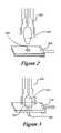
- FIG. 2is a diagram showing the shape and footprint of a plasma discharge from a RAP torch such as that shown in FIG. 1 .
- FIG. 3is a diagram showing the shape and footprint of the plasma discharge of FIG. 2 while passing the discharge through an aperture in accordance with one embodiment of the present invention.
- FIG. 4is a top view of a liquid-cooled aperture device that can be used with the torch of FIG. 1 .
- FIG. 5is a perspective view of a trench that can be formed in a substrate using the torch of FIG. 2 .
- FIG. 6is a perspective view of a trench that can be formed in a substrate by the torch and aperture combination of FIG. 3 .
- FIG. 7is a top view showing a multi-aperture device that can be used with the torch of FIG. 1 .
- FIGS. 8( a ) and 8 ( b )are diagrams of a plasma torch that can be used in place of the ICP RAP torch of FIG. 1 .
- FIG. 9is a diagram of an MIP torch system that can be used in accordance with another embodiment of the present invention.
- FIG. 10is a flowchart showing a process that can be used with the system of FIG. 2 .
- FIG. 2shows the shape of a plasma discharge 200 from a RAP torch 202 , without the discharge passing through an aperture 204 of an aperture device 206 .
- FIG. 3shows the same plasma discharge 200 being passed through the aperture 204 .
- the portion 208 of the plasma passing through the aperturehas a smaller effective diameter, measured horizontally in the Figure, resulting in a smaller active footprint.
- the aperture devicecan be any appropriate device, such as a high temperature metal or ceramic device having an opening that can allow passage of at least a portion of an impinging RAP plasma or RAP flame.
- the size of the aperturecan vary, and different apertures can be used with the same RAP torch to produce different footprints.
- the differing aperturescan be in the same aperture device, necessitating only a shift or rotation in the aperture device relative to the RAP torch in order to switch apertures.
- the differing aperturescan also be in separate aperture devices, requiring that the devices be switched out in order to change apertures.
- a number of torchescan be used, with each torch having an aperture device with a differently-sized aperture.
- Any appropriate devicecan be used to position the aperture device(s), such as a pneumatic, solenoid or stepper motor driven actuator in combination with a control mechanism.
- variable-diameter aperturescan be used. The use of a variable aperture can allow for “on-the-fly” adjustment of the torch footprint size and shape, as well as reduction of the heat load on the workpiece.
- FIG. 10An exemplary process that can take advantage of differently sized apertures is shown in the flowchart of FIG. 10 .
- an annular plasmais struck on a RAP torch, 900 .
- a flow of reactive speciesis injected into the center of the annular plasma 902 , the reactive species being selected as being capable of chemically reacting with the surface material of the workpiece being processed.
- the appropriate footprint size to be used in processing the workpiececan be determined 904 , such as by using a footprint calculation program or algorithm.
- An aperture of appropriate sizecan be selected, in an aperture device of an appropriate material 906 .
- the material of the aperture devicecan be selected based on, for example, the heat capacity and reactive nature of the material.
- the aperture devicecan be positioned such that the aperture is between the plasma and the workpiece, with the aperture being positioned such that the impinging plasma has the appropriate footprint 908 .
- the footprintcan be determined, for example, at the point along the primary axis of the plasma (vertical in FIG. 1 ) at which the proper amount of heat will be applied to the workpiece, such that the torch can be moved an appropriate distance from the workpiece.
- reactive atom plasma processingcan be used to modify the surface of the workpiece 910 , such as to etch, smooth, polish, clean, and/or deposit material onto the workpiece.
- the torch and/or workpiececan be moved relative to each other in order to process the necessary portion(s) of the workpiece.
- the movementcan be any appropriate movement, such as along a predetermined path, along a raster or “fixed” pattern, or can be determined dynamically be measuring the surface to be modified.
- an aperture devicecan be electrically isolated.
- the electric isolationcan occur in one embodiment by suspending the aperture device from an insulating rod, such as a ceramic rod, having a high melting point.
- an aperture devicecan be constructed of an appropriate material, such as stainless steel, platinum, or a high-temperature ceramic.
- a temperature-reducing devicesuch as an electrically-isolated water chiller can be used to liquid cool the aperture. Such a device is shown in FIG. 4 .
- a channel 304 in the aperture device 300allows a flow of liquid or gas to circulate about the aperture 302 in order to remove heat from the area about the aperture. If liquid is circulated through the channel 304 , for example, the liquid can be cooled in order to further reduce or remove heat from the aperture device 300 .
- the flamecan be physically confined while passing through the aperture, depending upon the shape and size of the aperture compared to that portion of the flame passing through the aperture.
- the only lower limit on the size of the resulting tool footprintis the size at which a hole or opening can be created, such as by drilling, in the chosen aperture material.
- a variety of different tool shapescan also be obtained through the use of differently shaped apertures.
- An apertureitself can take on a variety of shapes and sizes, such as multiple holes, non-circular openings, irregular shapes, and slits tailored to the specific application at hand.
- Plasma torchestypically have Gaussian discharges, such that a trench formed in a workpiece using such a torch will have a Gaussian cross-section regardless of the size of the footprint.
- FIG. 5shows a trench 402 that could be formed in a workpiece 400 using a standard RAP torch such as that shown in FIG. 2 .
- FIG. 6shows another trench 502 that could be formed in a workpiece 500 .
- the trenches in FIGS. 5 and 6have different widths in cross-section, due to the use of an aperture in one instance, but still retain the basic Gaussian shape.
- An added benefit of using an aperture with such a systemis the reduction of the overall heat flux into the work piece.
- An aperturecan absorb some of the heat, and can also act to deflect some of the incident plasma/heat away from the workpiece. The ability of an aperture to deflect heat allows a RAP process to be applied to heat sensitive materials.
- the central part of a plasmacan contain the highest concentration of reactive species, but a lower heat concentration. In the case of annular plasmas, the largest amount of heat can be in the outermost region of the discharge. For such a configuration, a centrally positioned aperture of the proper diameter can allow for a desirable combination of high etch rate and low heat load.
- a non-reactive precursor for use as a reactive atomcan cause a certain amount of energy to be supplied to the plasma, typically in the form of heat.
- the bulk of the heatcan be contained in the outer sheath of argon gas.
- the use of an apertureeffectively deflects a substantial portion of the gas and its concomitant energy away from the workpiece. With the correct range of aperture sizes, a suitable amount of argon remains to act as a protective sheath, blanketing the part and keeping the native atmosphere from the reactive species. The separation of these two zones improves the process by limiting the amount of reactive species lost through recombination and by reducing the post-process interaction of the reaction products with the residual gas in the work chamber.
- An apertureshould typically be constructed of a material that is capable of handling the high temperatures generated by the plasma or flame with which the aperture is to be used. Simple apertures in materials such as stainless steel, platinum, and ceramics can be sufficient for short exposure times. For longer exposure times, it can be necessary to apply active cooling to material surrounding the aperture. As discussed above, liquid cooling can be used wherein channels are fashioned in the material surrounding the aperture in order to allow rapid flow of water or another desired coolant.
- FIG. 7Another embodiment in accordance with the invention utilizes a configuration in which several apertures are situated in a circular arrangement on a rotary turret, such as that shown in FIG. 7 .
- seven apertures 602 , 604 , 606 , 608 , 610 , 612 , and 614are included in the rotary turret, with each fixed aperture having a different diameter.
- a variable aperture 616is also shown in the turret 600 .
- the variable aperturecan be sized such that the effective diameter of the aperture varies from a completely closed configuration to a completely open configuration that allows the plasma to pass without contacting the aperture. Having a completely closed configuration provides a position on the turret where no heat or plasma will be applied to the workpiece.
- variable aperturecan be of any appropriate design known to vary the size of an aperture, such as those used in camera applications.
- the turretitself can be made of any appropriate material, such as those mentioned above with respect to aperture devices. Such a turret allows individual apertures to be rotated into the plasma flame and quickly replaced. While apertures of different sizes allow for rapid changing of the tool footprint size, the use of identical apertures on a turret can circumvent problems arising from excessive heating of a single aperture. Active cooling of each aperture, such as that described with respect to FIG. 4 , can be utilized to further lengthen the service time of a single aperture in a multiple aperture system. Plasma temperatures are relatively high, but the heat capacity is not necessarily high, such that a number of materials can be used without a problem of sputter.
- RAP processesthat can be used in accordance with embodiments of the present invention include those described in pending U.S. patent application Ser. Nos. 10/008,236, 10/383,478, and 10/384,506, which are incorporated herein by reference above.
- FIG. 1shows a reactive atom plasma (RAP) system that can be used in accordance with embodiments of the present invention.
- FIG. 1shows a plasma torch in a plasma box 106 .
- the torchconsists of an inner tube 134 , an outer tube 138 , and an intermediate tube 136 .
- the inner tube 134has a gas inlet 100 for receiving a stream of reactive precursor gas 142 from a mass flow controller 118 .
- the torchcan utilize different precursor gases during different processing steps. For instance, the torch might utilize a precursor adapted to clean a particular contaminant off a surface in a first step, while utilizing a precursor for redistributing material on the surface of the workpiece during a second step.
- the intermediate tube 136has a gas inlet 102 that can be used to, for example, receive an auxiliary gas from the flow controller 118 .
- the outer tube 138has a gas inlet 104 that can be used to receive plasma gas from the mass flow controller 118 .
- the mass flow controller 118can receive the necessary gases from a number of gas supplies 120 , 122 , 124 , 126 , and can control the amount and rate of gases passed to the respective tube of the torch.
- the torch assemblycan generate and sustain plasma discharge 108 , which can be used to clean then shape or polish a workpiece 110 located on a chuck 112 , which can be located in a workpiece box 114 .
- a workpiece box 114can have an exhaust 132 for carrying away any process gases or products resulting from, for example, the interaction of the plasma discharge 108 and the workpiece 110 .
- the chuck 112 in this embodimentis in communication with a translation stage 116 , which is adapted to translate and/or rotate a workpiece 110 on the chuck 112 with respect to the plasma discharge 108 .
- the translation stage 116is in communication with a computer control system 130 , such as may be programmed to provide the necessary information or control to the translation stage 116 to allow the workpiece 110 to be moved along a proper path to achieve a desired cleaning, shaping, and/or polishing of the workpiece.
- the computer control system 130is in communication with an RF power supply 128 , which supplies power to the torch.
- the computer control system 130also provides the necessary information to the mass flow controller 118 .
- An induction coil 140surrounds the outer tube 138 of the torch near the plasma discharge 108 . Current from the RF power supply 128 flows through the coil 140 around the end of the torch. This energy is coupled into the plasma.
- RAP systemthat can be used in accordance with embodiments of the present invention can utilize a simple flame, such as a hydrogen-oxygen (H 2 /O 2 ) flame that is adjusted to burn with an excess of oxygen.
- a simple flamesuch as a hydrogen-oxygen (H 2 /O 2 ) flame that is adjusted to burn with an excess of oxygen.
- H 2 /O 2hydrogen-oxygen
- a device using such a simple flamecan be cheaper, easier to develop and maintain, and significantly more flexible than an ICP device.
- Existing H 2 /O 2 torchesare principally used for quartz glass blowing and by jewelers for melting platinum. Such torches can also have significantly smaller footprints than ICP devices.
- a flame torch 700can be designed in several ways.
- a reactive precursor gascan be mixed with either the fuel or the oxidizer gas before being injected into the torch through the fuel input 702 or the oxidizer input 704 .
- a standard torchcould be used to inject the precursor into the flame 706 .
- the torch headmight have to be made with specific materials. For example, mixing chlorine or chlorine-containing molecules into an H 2 /O 2 torch can produce reactive chlorine radicals.
- the slightly more complex exemplary design of FIG. 8( b )can introduce the reactive precursor gas into the flame 706 using a small tube 708 in the center of the torch 700 orifice.
- the flame 706in this case is usually chemically balanced and is neither a reducing nor oxidizing flame.
- gases, liquids, or solidscan be introduced coaxially into the flame to produce reactive components.
- the torch in this embodimentcan produce, for example, O, Cl, and F radicals from solid, liquid, and gaseous precursors.
- a stream of hot, reactive speciescan be produced that can chemically combine with the surface of a part or workpiece.
- a gasis produced that can leave the surface.
- a RAP systemcan operate over a wide range of pressures. Its most useful implementation can involve operation at or near atmospheric pressure, facilitating the treatment of large workpieces that cannot easily be placed in a vacuum chamber. The ability to work without a vacuum chamber can greatly increase throughput and reduce the cost of the tool that embodies the process.
- the flame systemcan easily be used with a multi-nozzle burner or multi-head torch to quickly cover large areas of the surface. For other applications, a small flame can be produced that affects an area on the surface as small as about 0.2 mm full width-half maximum (FWHM) for a Gaussian- or nearly Gaussian-shaped tool. Another advantage of the flame system is that it does not require an expensive RF power generator nor shielding from RF radiation. In fact, it can be a hand-held device, provided that adequate exhaust handing equipment and user safety devices are utilized. Further, a flame torch is not limited to a H 2 —O 2 flame torch. Any flame torch that is capable of accepting a source of reactive species, and fragmenting the reactive species into atomic radicals that can react with the surface, can be appropriate.
- FIG. 9another RAP system that can be used in accordance with the present invention utilizes a microwave-induced plasma (MIP) source.
- MIPmicrowave-induced plasma
- a MIP sourcehas proven to have a number of attributes that complement, or even surpass in some applications, the use of an ICP tool or a flame as an atomization source.
- the plasmacan be contained in a quartz torch 800 , which is distinguished from a standard ICP by the use of two concentric tubes instead of three. With a large enough bore, a torroidal plasma can be generated and the precursor injected into the center of the torch in a manner analogous to the ICP.
- a helical insert 808can be placed between the outer tube 802 and the inner tube 804 of the torch 800 to control tube concentricity, as well as to increase the tangential velocity of gas.
- the vortex flowcan help stabilize the system, and the high velocity can aid in cooling the quartz tubes 802 , 804 .
- the main portion of the microwave cavity 812can be any appropriate shape, such as a circular or cylindrical chamber, and can be machined from a highly conductive material, such as copper.
- the energy from a 2.45 GHz (or other appropriate) power supply 830can be coupled into the cavity 812 through a connector 814 on one edge of the cavity.
- the cavity 812can be tuned in one embodiment by moving a hollow cylindrical plunger 806 , or tuning device, into or out of the cavity 812 .
- the quartz torch 800is contained in the center of the tuning device 806 but does not move while the system is being tuned.
- An external gas sheath 820can be used to shield the plasma 820 from the atmosphere.
- the sheath 820confines and can contribute to the longevity of the reactive species in the plasma, and can keep the atmospheric recombination products as low as practically possible.
- the end of the sheath 820is approximately coplanar with the open end, or tip, of the torch 800 .
- the sheath 820can be extended beyond the tip of the torch 800 by installing an extension tube 822 using a threaded flange at the outlet of the sheath 820 .
- the sheath itselfcan be threadably attached 818 to the main cavity 812 , which can allow a fine adjustment on height to be made by screwing the sheath either toward or away from the cavity 812 .
- the sheath 820 or the extension tube 822can include an aperture in order to control the tool footprint. Apertures could then be changed simply by replacing the extension tube or sheath with an extension tube or sheath having a different size aperture, for example.
- a supply of process gas 828can provide process gas to both tubes 802 , 804 of the torch 800 .
- this process gasis primarily composed of argon or helium, but can also include carbon dioxide, oxygen or nitrogen, as well as other gases, if the chemistry of the situation permits. Gas flows in this embodiment can be between about one and about ten liters per minute.
- the gases introduced to the torchcan vary on the application.
- Reactive precursor gas(es)can be introduced to clean a surface, followed by a different precursor gas(es) to shape or otherwise modify the surface of the workpiece. This allows a workpiece to be cleaned and processed in a single chamber without a need to transfer the workpiece to different devices to accomplish each objective.
- a reactive atom plasma process in accordance with embodiments of the present inventionis based, at least in part, on the reactive chemistry of atomic radicals and reactive fragments formed by the interaction of a non-reactive precursor chemical with a plasma.
- the atomic radicals formed by the decomposition of a non-reactive precursorinteract with material of the surface of the part being modified.
- the surface materialis transformed to a gaseous reaction product and leaves the surface.
- a variety of materialscan be processed using different chemical precursors and different plasma compositions.
- the products of the surface reaction in this processmust be a gas under the conditions of the plasma exposure. If not, a surface reaction residue can build up on the surface which will impede further etching.
- the reactive precursor chemicalcan be introduced as a gas.
- a reactive precursorcould also be introduced to the plasma in either liquid or solid form.
- Liquidscan be aspirated into the plasma and fine powders can be nebulized by mixing with a gas before introduction to the plasma.
- RAP processingcan be used at atmospheric pressure.
- RAPcan be used as a sub-aperture tool to precisely clean and shape surfaces.
- a standard, commercially-available two- or three-tube torchcan be used.
- the outer tubecan handle the bulk of the plasma gas, while the inner tube can be used to inject the reactive precursor.
- Energycan be coupled into the discharge in an annular region inside the torch. As a result of this coupling zone and the ensuing temperature gradient, a simple way to introduce the reactive gas, or a material to be deposited, is through the center.
- the reactive gascan also be mixed directly with the plasma gas, although the quartz tube can erode under this configuration and the system loses the benefit of the inert outer gas sheath.
- Injecting the reactive precursor into the center of the excitation zonehas several important advantages over other techniques.
- Some atmospheric plasma jet systemssuch as ADP, mix the precursor gas in with the plasma gas, creating a uniform plume of reactive species. This exposes the electrodes or plasma tubes to the reactive species, leading to erosion and contamination of the plasma.
- the reactive precursoris introduced around the edge of the excitation zone, which also leads to direct exposure of the electrodes and plasma contamination.
- the reactive species in the RAP systemare enveloped by a sheath of argon, which not only reduces the plasma torch erosion but also reduces interactions between the reactive species and the atmosphere.
- the inner diameter of the outer tubecan be used to control the size of the discharge. On a standard torch, this can be on the order of about 18 to about 24 mm. The size can be somewhat frequency-dependent, with larger sizes being required by lower frequencies. In an attempt to shrink such a system, torches of a two tube design can be constructed that have an inner diameter of, for example, about 14 mm. Smaller inner diameters may be used with microwave excitation, or higher frequency, sources.
Landscapes
- Physics & Mathematics (AREA)
- Engineering & Computer Science (AREA)
- Plasma & Fusion (AREA)
- Electromagnetism (AREA)
- Spectroscopy & Molecular Physics (AREA)
- Plasma Technology (AREA)
Abstract
Description
Claims (45)
Priority Applications (3)
| Application Number | Priority Date | Filing Date | Title |
|---|---|---|---|
| US10/911,821US7304263B2 (en) | 2003-08-14 | 2004-08-05 | Systems and methods utilizing an aperture with a reactive atom plasma torch |
| PCT/US2004/025410WO2005020646A2 (en) | 2003-08-14 | 2004-08-06 | Reactive atom plasma torch aperture system |
| US11/875,787US20080035612A1 (en) | 2003-08-14 | 2007-10-19 | Systems and Methods Utilizing an Aperture with a Reactive Atom Plasma Torch |
Applications Claiming Priority (2)
| Application Number | Priority Date | Filing Date | Title |
|---|---|---|---|
| US49517603P | 2003-08-14 | 2003-08-14 | |
| US10/911,821US7304263B2 (en) | 2003-08-14 | 2004-08-05 | Systems and methods utilizing an aperture with a reactive atom plasma torch |
Related Child Applications (1)
| Application Number | Title | Priority Date | Filing Date |
|---|---|---|---|
| US11/875,787ContinuationUS20080035612A1 (en) | 2003-08-14 | 2007-10-19 | Systems and Methods Utilizing an Aperture with a Reactive Atom Plasma Torch |
Publications (2)
| Publication Number | Publication Date |
|---|---|
| US20050061782A1 US20050061782A1 (en) | 2005-03-24 |
| US7304263B2true US7304263B2 (en) | 2007-12-04 |
Family
ID=34221377
Family Applications (2)
| Application Number | Title | Priority Date | Filing Date |
|---|---|---|---|
| US10/911,821Expired - Fee RelatedUS7304263B2 (en) | 2003-08-14 | 2004-08-05 | Systems and methods utilizing an aperture with a reactive atom plasma torch |
| US11/875,787AbandonedUS20080035612A1 (en) | 2003-08-14 | 2007-10-19 | Systems and Methods Utilizing an Aperture with a Reactive Atom Plasma Torch |
Family Applications After (1)
| Application Number | Title | Priority Date | Filing Date |
|---|---|---|---|
| US11/875,787AbandonedUS20080035612A1 (en) | 2003-08-14 | 2007-10-19 | Systems and Methods Utilizing an Aperture with a Reactive Atom Plasma Torch |
Country Status (2)
| Country | Link |
|---|---|
| US (2) | US7304263B2 (en) |
| WO (1) | WO2005020646A2 (en) |
Cited By (11)
| Publication number | Priority date | Publication date | Assignee | Title |
|---|---|---|---|---|
| US20020148560A1 (en)* | 2001-01-30 | 2002-10-17 | Carr Jeffrey W. | Apparatus and method for atmospheric pressure reactive atom plasma processing for shaping of damage free surfaces |
| US20070261383A1 (en)* | 2004-09-27 | 2007-11-15 | Siemens Aktiengesellschaft | Method and Device For Influencing Combustion Processes, In Particular During the Operation of a Gas Turbine |
| US7591957B2 (en) | 2001-01-30 | 2009-09-22 | Rapt Industries, Inc. | Method for atmospheric pressure reactive atom plasma processing for surface modification |
| US7955513B2 (en) | 2001-11-07 | 2011-06-07 | Rapt Industries, Inc. | Apparatus and method for reactive atom plasma processing for material deposition |
| US20140073138A1 (en)* | 2012-09-12 | 2014-03-13 | Ming-Yu Huang | Method for plasma etching and plasma etching apparatus thereof |
| US8721906B2 (en) | 2008-06-09 | 2014-05-13 | Poco Graphite, Inc. | Method to increase yield and reduce down time in semiconductor fabrication units by preconditioning components using sub-aperture reactive atom etch |
| US9574268B1 (en)* | 2011-10-28 | 2017-02-21 | Asm America, Inc. | Pulsed valve manifold for atomic layer deposition |
| US10662527B2 (en) | 2016-06-01 | 2020-05-26 | Asm Ip Holding B.V. | Manifolds for uniform vapor deposition |
| US11208722B2 (en) | 2011-12-27 | 2021-12-28 | Asm Ip Holding B.V. | Vapor flow control apparatus for atomic layer deposition |
| US11492701B2 (en) | 2019-03-19 | 2022-11-08 | Asm Ip Holding B.V. | Reactor manifolds |
| US11830731B2 (en) | 2019-10-22 | 2023-11-28 | Asm Ip Holding B.V. | Semiconductor deposition reactor manifolds |
Families Citing this family (13)
| Publication number | Priority date | Publication date | Assignee | Title |
|---|---|---|---|---|
| SG96665A1 (en)* | 2001-11-21 | 2003-06-16 | Environmental Technology Inst | An apparatus and method for cleaning glass substrates using a cool hydrogen flame |
| US7297892B2 (en)* | 2003-08-14 | 2007-11-20 | Rapt Industries, Inc. | Systems and methods for laser-assisted plasma processing |
| US20060128165A1 (en)* | 2004-12-13 | 2006-06-15 | 3M Innovative Properties Company | Method for patterning surface modification |
| US7996987B2 (en)* | 2006-10-17 | 2011-08-16 | Broadcom Corporation | Single footprint family of integrated power modules |
| EP2566650B1 (en)* | 2010-05-05 | 2019-10-02 | PerkinElmer Health Sciences, Inc. | Inductive devices and low flow plasmas using them |
| US8669521B2 (en)* | 2010-09-24 | 2014-03-11 | Wisconsin Alumni Research Foundation | Microwave cavity detector for mass spectrometry |
| CN103227092A (en)* | 2013-05-14 | 2013-07-31 | 哈尔滨工业大学 | Atmospheric plasma processing method of free-form surface microstructure optical parts |
| CN103273180B (en)* | 2013-05-14 | 2015-11-25 | 哈尔滨工业大学 | The atmosphere plasma numerical-control processing method of freeform optics part |
| CN103212774B (en)* | 2013-05-14 | 2015-07-01 | 哈尔滨工业大学 | Device for atmospheric plasma digital control processing of free curved surface optical parts |
| US20160135277A1 (en)* | 2014-11-11 | 2016-05-12 | Agilent Technologies, Inc. | Reduction of ambient gas entrainment and ion current noise in plasma based spectrometry |
| WO2023203386A2 (en)* | 2022-04-22 | 2023-10-26 | Standard Biotools Canada Inc. | Sealed plasma torch |
| AT526238B1 (en)* | 2022-08-09 | 2024-01-15 | Thermal Proc Solutions Gmbh | Device for providing a plasma |
| AT526239B1 (en)* | 2022-08-09 | 2024-01-15 | Thermal Proc Solutions Gmbh | Device for providing a plasma |
Citations (10)
| Publication number | Priority date | Publication date | Assignee | Title |
|---|---|---|---|---|
| US4532199A (en) | 1983-03-01 | 1985-07-30 | Tokyo Shibaura Denki Kabushiki Kaisha | Method of forming amorphous silicon film |
| EP0546842A1 (en) | 1991-12-13 | 1993-06-16 | Hughes Aircraft Company | Methods and apparatus for confinement of a plasma etch region for precision shaping of surfaces of substances |
| US5256205A (en) | 1990-05-09 | 1993-10-26 | Jet Process Corporation | Microwave plasma assisted supersonic gas jet deposition of thin film materials |
| US5468955A (en)* | 1994-12-20 | 1995-11-21 | International Business Machines Corporation | Neutral beam apparatus for in-situ production of reactants and kinetic energy transfer |
| US5629054A (en)* | 1990-11-20 | 1997-05-13 | Canon Kabushiki Kaisha | Method for continuously forming a functional deposit film of large area by micro-wave plasma CVD method |
| US5683548A (en) | 1996-02-22 | 1997-11-04 | Motorola, Inc. | Inductively coupled plasma reactor and process |
| DE19925790A1 (en)* | 1999-06-05 | 2000-12-07 | Inst Oberflaechenmodifizierung | High rate processing of material surfaces especially in optical applications, microelectronics or in microsystems comprises using a plasma beam source |
| WO2002061171A1 (en) | 2001-02-02 | 2002-08-08 | Robert Bosch Gmbh | Method for the production of a functional coating by means of a high-frequency icp plasma beam source |
| US6660177B2 (en)* | 2001-11-07 | 2003-12-09 | Rapt Industries Inc. | Apparatus and method for reactive atom plasma processing for material deposition |
| US6663231B2 (en)* | 2000-02-24 | 2003-12-16 | Samsung Electronics Co., Ltd. | Monolithic nozzle assembly formed with mono-crystalline silicon wafer and method for manufacturing the same |
Family Cites Families (95)
| Publication number | Priority date | Publication date | Assignee | Title |
|---|---|---|---|---|
| US3264508A (en)* | 1962-06-27 | 1966-08-02 | Lai William | Plasma torch |
| BE795891A (en)* | 1972-02-23 | 1973-06-18 | Electricity Council | PLASMA TORCH IMPROVEMENTS |
| US4035604A (en)* | 1973-01-17 | 1977-07-12 | Rolls-Royce (1971) Limited | Methods and apparatus for finishing articles |
| FR2224991A5 (en)* | 1973-04-05 | 1974-10-31 | France Etat | |
| BE806181A (en)* | 1973-10-17 | 1974-02-15 | Soudure Autogene Elect | PROCESS FOR PRIMING A COLUMN OF PLASMA INSIDE AN ENCLOSURE AND ROD-ELECTRODE FOR THE EXECUTION OF THE SAID PROCESS |
| JPS5673539A (en)* | 1979-11-22 | 1981-06-18 | Toshiba Corp | Surface treating apparatus of microwave plasma |
| US4431898A (en)* | 1981-09-01 | 1984-02-14 | The Perkin-Elmer Corporation | Inductively coupled discharge for plasma etching and resist stripping |
| US4439463A (en)* | 1982-02-18 | 1984-03-27 | Atlantic Richfield Company | Plasma assisted deposition system |
| US4440558A (en)* | 1982-06-14 | 1984-04-03 | International Telephone And Telegraph Corporation | Fabrication of optical preforms by axial chemical vapor deposition |
| US4440556A (en)* | 1982-06-23 | 1984-04-03 | International Telephone And Telegraph Corporation | Optical fiber drawing using plasma torch |
| US4431901A (en)* | 1982-07-02 | 1984-02-14 | The United States Of America As Represented By The United States Department Of Energy | Induction plasma tube |
| US4689467A (en)* | 1982-12-17 | 1987-08-25 | Inoue-Japax Research Incorporated | Laser machining apparatus |
| US4668366A (en)* | 1984-08-02 | 1987-05-26 | The Perkin-Elmer Corporation | Optical figuring by plasma assisted chemical transport and etching apparatus therefor |
| US4674683A (en)* | 1986-05-06 | 1987-06-23 | The Perkin-Elmer Corporation | Plasma flame spray gun method and apparatus with adjustable ratio of radial and tangential plasma gas flow |
| US4897282A (en)* | 1986-09-08 | 1990-01-30 | Iowa State University Reserach Foundation, Inc. | Thin film coating process using an inductively coupled plasma |
| US4739147A (en)* | 1987-01-30 | 1988-04-19 | The Dow Chemical Company | Pre-aligned demountable plasma torch |
| FR2616614B1 (en)* | 1987-06-10 | 1989-10-20 | Air Liquide | MICROWAVE PLASMA TORCH, DEVICE COMPRISING SUCH A TORCH AND METHOD FOR MANUFACTURING POWDER USING THE SAME |
| US5007771A (en)* | 1988-02-01 | 1991-04-16 | Keystone Environmental Resources, Inc. | Method for treating contaminated soil by biological degradation on a sloped surface |
| JP2805009B2 (en)* | 1988-05-11 | 1998-09-30 | 株式会社日立製作所 | Plasma generator and plasma element analyzer |
| US5106827A (en)* | 1989-09-18 | 1992-04-21 | The Perkin Elmer Corporation | Plasma assisted oxidation of perovskites for forming high temperature superconductors using inductively coupled discharges |
| US6068784A (en)* | 1989-10-03 | 2000-05-30 | Applied Materials, Inc. | Process used in an RF coupled plasma reactor |
| US5000771A (en)* | 1989-12-29 | 1991-03-19 | At&T Bell Laboratories | Method for manufacturing an article comprising a refractory dielectric body |
| CA2037660C (en)* | 1990-03-07 | 1997-08-19 | Tadashi Kamimura | Methods of modifying surface qualities of metallic articles and apparatuses therefor |
| US5095189A (en)* | 1990-09-26 | 1992-03-10 | General Electric Company | Method for reducing plasma constriction by intermediate injection of hydrogen in RF plasma gun |
| US5200595A (en)* | 1991-04-12 | 1993-04-06 | Universite De Sherbrooke | High performance induction plasma torch with a water-cooled ceramic confinement tube |
| US5291415A (en)* | 1991-12-13 | 1994-03-01 | Hughes Aircraft Company | Method to determine tool paths for thinning and correcting errors in thickness profiles of films |
| US5290382A (en)* | 1991-12-13 | 1994-03-01 | Hughes Aircraft Company | Methods and apparatus for generating a plasma for "downstream" rapid shaping of surfaces of substrates and films |
| US5206471A (en)* | 1991-12-26 | 1993-04-27 | Applied Science And Technology, Inc. | Microwave activated gas generator |
| US5280154A (en)* | 1992-01-30 | 1994-01-18 | International Business Machines Corporation | Radio frequency induction plasma processing system utilizing a uniform field coil |
| US5302237A (en)* | 1992-02-13 | 1994-04-12 | The United States Of America As Represented By The Secretary Of Commerce | Localized plasma processing |
| US5238532A (en)* | 1992-02-27 | 1993-08-24 | Hughes Aircraft Company | Method and apparatus for removal of subsurface damage in semiconductor materials by plasma etching |
| US5292400A (en)* | 1992-03-23 | 1994-03-08 | Hughes Aircraft Company | Method and apparatus for producing variable spatial frequency control in plasma assisted chemical etching |
| EP0595159B1 (en)* | 1992-10-26 | 1997-12-29 | Schott Glaswerke | Process and apparatus for interior coating of strongly curved, essentially dome-shaped substrates by CVD |
| US5429730A (en)* | 1992-11-02 | 1995-07-04 | Kabushiki Kaisha Toshiba | Method of repairing defect of structure |
| US5346578A (en)* | 1992-11-04 | 1994-09-13 | Novellus Systems, Inc. | Induction plasma source |
| CA2084281C (en)* | 1992-12-01 | 1999-07-06 | Roberto Nunes Szente | Plasma torch for central injection depositing |
| US5386119A (en)* | 1993-03-25 | 1995-01-31 | Hughes Aircraft Company | Apparatus and method for thick wafer measurement |
| US5430355A (en)* | 1993-07-30 | 1995-07-04 | Texas Instruments Incorporated | RF induction plasma source for plasma processing |
| US5419803A (en)* | 1993-11-17 | 1995-05-30 | Hughes Aircraft Company | Method of planarizing microstructures |
| US5591068A (en)* | 1995-03-13 | 1997-01-07 | Regents Of The University Of California | Precision non-contact polishing tool |
| US6821500B2 (en)* | 1995-03-14 | 2004-11-23 | Bechtel Bwxt Idaho, Llc | Thermal synthesis apparatus and process |
| US5795493A (en)* | 1995-05-01 | 1998-08-18 | Motorola, Inc. | Laser assisted plasma chemical etching method |
| US5650032A (en)* | 1995-06-06 | 1997-07-22 | International Business Machines Corporation | Apparatus for producing an inductive plasma for plasma processes |
| JPH0964321A (en)* | 1995-08-24 | 1997-03-07 | Komatsu Electron Metals Co Ltd | Manufacture of soi substrate |
| US6017221A (en)* | 1995-12-04 | 2000-01-25 | Flamm; Daniel L. | Process depending on plasma discharges sustained by inductive coupling |
| JPH09251935A (en)* | 1996-03-18 | 1997-09-22 | Applied Materials Inc | Plasma ignition device, semiconductor manufacturing apparatus using plasma, and plasma ignition method for semiconductor device |
| JP3620554B2 (en)* | 1996-03-25 | 2005-02-16 | 信越半導体株式会社 | Semiconductor wafer manufacturing method |
| US5932293A (en)* | 1996-03-29 | 1999-08-03 | Metalspray U.S.A., Inc. | Thermal spray systems |
| US6245202B1 (en)* | 1996-04-12 | 2001-06-12 | Hitachi, Ltd. | Plasma treatment device |
| US5928527A (en)* | 1996-04-15 | 1999-07-27 | The Boeing Company | Surface modification using an atmospheric pressure glow discharge plasma source |
| KR20000016136A (en)* | 1996-05-31 | 2000-03-25 | 피터 무몰라 | Method for treating articles with a plasma jet |
| US6105534A (en)* | 1996-05-31 | 2000-08-22 | Ipec Precision, Inc. | Apparatus for plasma jet treatment of substrates |
| KR20000016138A (en)* | 1996-05-31 | 2000-03-25 | 피터 무몰라 | Apparatus for generating and deflecting a plasma jet |
| US6209480B1 (en)* | 1996-07-10 | 2001-04-03 | Mehrdad M. Moslehi | Hermetically-sealed inductively-coupled plasma source structure and method of use |
| US6170428B1 (en)* | 1996-07-15 | 2001-01-09 | Applied Materials, Inc. | Symmetric tunable inductively coupled HDP-CVD reactor |
| US5897712A (en)* | 1996-07-16 | 1999-04-27 | Applied Materials, Inc. | Plasma uniformity control for an inductive plasma source |
| US6056848A (en)* | 1996-09-11 | 2000-05-02 | Ctp, Inc. | Thin film electrostatic shield for inductive plasma processing |
| US5767627A (en)* | 1997-01-09 | 1998-06-16 | Trusi Technologies, Llc | Plasma generation and plasma processing of materials |
| US5955383A (en)* | 1997-01-22 | 1999-09-21 | Taiwan Semiconductor Manufacturing Company Ltd. | Method for controlling etch rate when using consumable electrodes during plasma etching |
| US5800621A (en)* | 1997-02-10 | 1998-09-01 | Applied Materials, Inc. | Plasma source for HDP-CVD chamber |
| FR2764163B1 (en)* | 1997-05-30 | 1999-08-13 | Centre Nat Rech Scient | INDUCTIVE PLASMA TORCH WITH REAGENT INJECTOR |
| US5877471A (en)* | 1997-06-11 | 1999-03-02 | The Regents Of The University Of California | Plasma torch having a cooled shield assembly |
| DE19734278C1 (en)* | 1997-08-07 | 1999-02-25 | Bosch Gmbh Robert | Device for anisotropic etching of substrates |
| US5925266A (en)* | 1997-10-15 | 1999-07-20 | The Perkin-Elmer Corporation | Mounting apparatus for induction coupled plasma torch |
| US6194036B1 (en)* | 1997-10-20 | 2001-02-27 | The Regents Of The University Of California | Deposition of coatings using an atmospheric pressure plasma jet |
| US6093655A (en)* | 1998-02-12 | 2000-07-25 | Micron Technology, Inc. | Plasma etching methods |
| US6230719B1 (en)* | 1998-02-27 | 2001-05-15 | Micron Technology, Inc. | Apparatus for removing contaminants on electronic devices |
| US6085688A (en)* | 1998-03-27 | 2000-07-11 | Applied Materials, Inc. | Method and apparatus for improving processing and reducing charge damage in an inductively coupled plasma reactor |
| DE19814812C2 (en)* | 1998-04-02 | 2000-05-11 | Mut Mikrowellen Umwelt Technol | Plasma torch with a microwave transmitter |
| US6074947A (en)* | 1998-07-10 | 2000-06-13 | Plasma Sil, Llc | Process for improving uniform thickness of semiconductor substrates using plasma assisted chemical etching |
| US6218640B1 (en)* | 1999-07-19 | 2001-04-17 | Timedomain Cvd, Inc. | Atmospheric pressure inductive plasma apparatus |
| US6041623A (en)* | 1998-08-27 | 2000-03-28 | Lucent Technologies Inc. | Process for fabricating article comprising refractory dielectric body |
| US6406590B1 (en)* | 1998-09-08 | 2002-06-18 | Sharp Kaubushiki Kaisha | Method and apparatus for surface treatment using plasma |
| KR100277833B1 (en)* | 1998-10-09 | 2001-01-15 | 정선종 | Radio Wave Induced Plasma Source Generator |
| DE69929271T2 (en)* | 1998-10-26 | 2006-09-21 | Matsushita Electric Works, Ltd., Kadoma | Apparatus and method for plasma treatment |
| US6028286A (en)* | 1998-12-30 | 2000-02-22 | Lam Research Corporation | Method for igniting a plasma inside a plasma processing reactor |
| US6579805B1 (en)* | 1999-01-05 | 2003-06-17 | Ronal Systems Corp. | In situ chemical generator and method |
| US6262523B1 (en)* | 1999-04-21 | 2001-07-17 | The Regents Of The University Of California | Large area atmospheric-pressure plasma jet |
| US6239553B1 (en)* | 1999-04-22 | 2001-05-29 | Applied Materials, Inc. | RF plasma source for material processing |
| US6228330B1 (en)* | 1999-06-08 | 2001-05-08 | The Regents Of The University Of California | Atmospheric-pressure plasma decontamination/sterilization chamber |
| US6200908B1 (en)* | 1999-08-04 | 2001-03-13 | Memc Electronic Materials, Inc. | Process for reducing waviness in semiconductor wafers |
| US6229111B1 (en)* | 1999-10-13 | 2001-05-08 | The University Of Tennessee Research Corporation | Method for laser/plasma surface alloying |
| US6203661B1 (en)* | 1999-12-07 | 2001-03-20 | Trusi Technologies, Llc | Brim and gas escape for non-contact wafer holder |
| US6468833B2 (en)* | 2000-03-31 | 2002-10-22 | American Air Liquide, Inc. | Systems and methods for application of substantially dry atmospheric plasma surface treatment to various electronic component packaging and assembly methods |
| AUPQ861500A0 (en)* | 2000-07-06 | 2000-08-03 | Varian Australia Pty Ltd | Plasma source for spectrometry |
| US20020038689A1 (en)* | 2000-08-31 | 2002-04-04 | Rudolf Bayer | Reduced and atmospheric pressure process capable epitaxial chamber |
| US7351449B2 (en)* | 2000-09-22 | 2008-04-01 | N Gimat Co. | Chemical vapor deposition methods for making powders and coatings, and coatings made using these methods |
| US6534921B1 (en)* | 2000-11-09 | 2003-03-18 | Samsung Electronics Co., Ltd. | Method for removing residual metal-containing polymer material and ion implanted photoresist in atmospheric downstream plasma jet system |
| US7591957B2 (en)* | 2001-01-30 | 2009-09-22 | Rapt Industries, Inc. | Method for atmospheric pressure reactive atom plasma processing for surface modification |
| US6849306B2 (en)* | 2001-08-23 | 2005-02-01 | Konica Corporation | Plasma treatment method at atmospheric pressure |
| US20040118348A1 (en)* | 2002-03-07 | 2004-06-24 | Mills Randell L.. | Microwave power cell, chemical reactor, and power converter |
| FI121123B (en)* | 2002-03-14 | 2010-07-15 | Metso Paper Inc | A method for coating a continuous web surface with a dry coating powder |
| US20050018199A1 (en)* | 2003-07-24 | 2005-01-27 | Leblanc Philip R. | Fiber array interferometer for inspecting glass sheets |
| US7297892B2 (en)* | 2003-08-14 | 2007-11-20 | Rapt Industries, Inc. | Systems and methods for laser-assisted plasma processing |
| US20050061774A1 (en)* | 2003-08-14 | 2005-03-24 | Rapt Industries, Inc. | Apparatus and method for non-contact shaping and smoothing of damage-free glass substrates |
- 2004
- 2004-08-05USUS10/911,821patent/US7304263B2/ennot_activeExpired - Fee Related
- 2004-08-06WOPCT/US2004/025410patent/WO2005020646A2/enactiveApplication Filing
- 2007
- 2007-10-19USUS11/875,787patent/US20080035612A1/ennot_activeAbandoned
Patent Citations (10)
| Publication number | Priority date | Publication date | Assignee | Title |
|---|---|---|---|---|
| US4532199A (en) | 1983-03-01 | 1985-07-30 | Tokyo Shibaura Denki Kabushiki Kaisha | Method of forming amorphous silicon film |
| US5256205A (en) | 1990-05-09 | 1993-10-26 | Jet Process Corporation | Microwave plasma assisted supersonic gas jet deposition of thin film materials |
| US5629054A (en)* | 1990-11-20 | 1997-05-13 | Canon Kabushiki Kaisha | Method for continuously forming a functional deposit film of large area by micro-wave plasma CVD method |
| EP0546842A1 (en) | 1991-12-13 | 1993-06-16 | Hughes Aircraft Company | Methods and apparatus for confinement of a plasma etch region for precision shaping of surfaces of substances |
| US5468955A (en)* | 1994-12-20 | 1995-11-21 | International Business Machines Corporation | Neutral beam apparatus for in-situ production of reactants and kinetic energy transfer |
| US5683548A (en) | 1996-02-22 | 1997-11-04 | Motorola, Inc. | Inductively coupled plasma reactor and process |
| DE19925790A1 (en)* | 1999-06-05 | 2000-12-07 | Inst Oberflaechenmodifizierung | High rate processing of material surfaces especially in optical applications, microelectronics or in microsystems comprises using a plasma beam source |
| US6663231B2 (en)* | 2000-02-24 | 2003-12-16 | Samsung Electronics Co., Ltd. | Monolithic nozzle assembly formed with mono-crystalline silicon wafer and method for manufacturing the same |
| WO2002061171A1 (en) | 2001-02-02 | 2002-08-08 | Robert Bosch Gmbh | Method for the production of a functional coating by means of a high-frequency icp plasma beam source |
| US6660177B2 (en)* | 2001-11-07 | 2003-12-09 | Rapt Industries Inc. | Apparatus and method for reactive atom plasma processing for material deposition |
Non-Patent Citations (1)
| Title |
|---|
| International Search Report Mailed Oct. 31, 2005, PCT. |
Cited By (16)
| Publication number | Priority date | Publication date | Assignee | Title |
|---|---|---|---|---|
| US7510664B2 (en) | 2001-01-30 | 2009-03-31 | Rapt Industries, Inc. | Apparatus and method for atmospheric pressure reactive atom plasma processing for shaping of damage free surfaces |
| US7591957B2 (en) | 2001-01-30 | 2009-09-22 | Rapt Industries, Inc. | Method for atmospheric pressure reactive atom plasma processing for surface modification |
| US20020148560A1 (en)* | 2001-01-30 | 2002-10-17 | Carr Jeffrey W. | Apparatus and method for atmospheric pressure reactive atom plasma processing for shaping of damage free surfaces |
| US7955513B2 (en) | 2001-11-07 | 2011-06-07 | Rapt Industries, Inc. | Apparatus and method for reactive atom plasma processing for material deposition |
| US20070261383A1 (en)* | 2004-09-27 | 2007-11-15 | Siemens Aktiengesellschaft | Method and Device For Influencing Combustion Processes, In Particular During the Operation of a Gas Turbine |
| US8721906B2 (en) | 2008-06-09 | 2014-05-13 | Poco Graphite, Inc. | Method to increase yield and reduce down time in semiconductor fabrication units by preconditioning components using sub-aperture reactive atom etch |
| US20170121818A1 (en) | 2011-10-28 | 2017-05-04 | Asm America, Inc. | Pulsed valve manifold for atomic layer deposition |
| US9574268B1 (en)* | 2011-10-28 | 2017-02-21 | Asm America, Inc. | Pulsed valve manifold for atomic layer deposition |
| US10370761B2 (en) | 2011-10-28 | 2019-08-06 | Asm America, Inc. | Pulsed valve manifold for atomic layer deposition |
| US11208722B2 (en) | 2011-12-27 | 2021-12-28 | Asm Ip Holding B.V. | Vapor flow control apparatus for atomic layer deposition |
| US20140073138A1 (en)* | 2012-09-12 | 2014-03-13 | Ming-Yu Huang | Method for plasma etching and plasma etching apparatus thereof |
| US10662527B2 (en) | 2016-06-01 | 2020-05-26 | Asm Ip Holding B.V. | Manifolds for uniform vapor deposition |
| US11377737B2 (en) | 2016-06-01 | 2022-07-05 | Asm Ip Holding B.V. | Manifolds for uniform vapor deposition |
| US12416081B2 (en) | 2016-06-01 | 2025-09-16 | Asm Ip Holding B.V. | Manifolds for uniform vapor deposition |
| US11492701B2 (en) | 2019-03-19 | 2022-11-08 | Asm Ip Holding B.V. | Reactor manifolds |
| US11830731B2 (en) | 2019-10-22 | 2023-11-28 | Asm Ip Holding B.V. | Semiconductor deposition reactor manifolds |
Also Published As
| Publication number | Publication date |
|---|---|
| WO2005020646A3 (en) | 2009-04-02 |
| US20080035612A1 (en) | 2008-02-14 |
| WO2005020646A2 (en) | 2005-03-03 |
| US20050061782A1 (en) | 2005-03-24 |
Similar Documents
| Publication | Publication Date | Title |
|---|---|---|
| US20080035612A1 (en) | Systems and Methods Utilizing an Aperture with a Reactive Atom Plasma Torch | |
| US7297892B2 (en) | Systems and methods for laser-assisted plasma processing | |
| US7371992B2 (en) | Method for non-contact cleaning of a surface | |
| EP1366508B1 (en) | Method of and system for atmospheric pressure reactive atom plasma processing for surface modification | |
| US7955513B2 (en) | Apparatus and method for reactive atom plasma processing for material deposition | |
| Ichiki et al. | Localized and ultrahigh-rate etching of silicon wafers using atmospheric-pressure microplasma jets | |
| JP6295439B2 (en) | Plasma processing apparatus and method, and electronic device manufacturing method | |
| US7442271B2 (en) | Miniature microwave plasma torch application and method of use thereof | |
| US20040173316A1 (en) | Apparatus and method using a microwave source for reactive atom plasma processing | |
| KR102714917B1 (en) | Apparatus for treating substrate and method for treating substrate | |
| JP6465442B2 (en) | Plasma processing equipment | |
| KR101745131B1 (en) | Plasma processing apparatus, plasma processing method, and method for manufacturing electronic device | |
| JP6379355B2 (en) | Plasma processing apparatus and method, and electronic device manufacturing method | |
| KR102615846B1 (en) | Apparatus for cleaning component and method for cleaing component | |
| HU179994B (en) | Equipment for high temperature surface treating dielectric work pieces of straight generatrix | |
| JP2017182966A (en) | Plasma processing apparatus, plasma processing method, and electronic device manufacturing method | |
| JP2016062716A (en) | Device and method for plasma processing, and manufacturing method of electronic device | |
| JP2016225190A (en) | Plasma processing apparatus and method, and electronic device manufacturing method |
Legal Events
| Date | Code | Title | Description |
|---|---|---|---|
| AS | Assignment | Owner name:RAPT INDUSTRIES, INC., CALIFORNIA Free format text:ASSIGNMENT OF ASSIGNORS INTEREST;ASSIGNORS:CHANG, ANDREW;CARR, JEFFREY W.;KELLEY, JUDE;AND OTHERS;REEL/FRAME:016051/0464;SIGNING DATES FROM 20041123 TO 20041129 | |
| STCF | Information on status: patent grant | Free format text:PATENTED CASE | |
| AS | Assignment | Owner name:VENCORE SOLUTIONS, OREGON Free format text:SECURITY AGREEMENT;ASSIGNOR:RAPT INDUSTRIES INC., A CALIFORNIA CORPORATION;REEL/FRAME:022408/0040 Effective date:20081215 | |
| FEPP | Fee payment procedure | Free format text:PAT HOLDER NO LONGER CLAIMS SMALL ENTITY STATUS, ENTITY STATUS SET TO UNDISCOUNTED (ORIGINAL EVENT CODE: STOL); ENTITY STATUS OF PATENT OWNER: LARGE ENTITY | |
| REFU | Refund | Free format text:REFUND - SURCHARGE, PETITION TO ACCEPT PYMT AFTER EXP, UNINTENTIONAL (ORIGINAL EVENT CODE: R2551); ENTITY STATUS OF PATENT OWNER: LARGE ENTITY | |
| FPAY | Fee payment | Year of fee payment:4 | |
| AS | Assignment | Owner name:IMREAL ENTERPRISES, LLC, CALIFORNIA Free format text:ASSIGNMENT AND PURCHASE;ASSIGNOR:VENCORE SOLUTIONS LLC;REEL/FRAME:028920/0429 Effective date:20120904 | |
| AS | Assignment | Owner name:IMREAL ENTERPRISES, LLC, CALIFORNIA Free format text:ASSIGNMENT OF ASSIGNORS INTEREST;ASSIGNOR:RAPT INDUSTRIES, INC.;REEL/FRAME:029174/0420 Effective date:20121011 | |
| FPAY | Fee payment | Year of fee payment:8 | |
| FEPP | Fee payment procedure | Free format text:MAINTENANCE FEE REMINDER MAILED (ORIGINAL EVENT CODE: REM.); ENTITY STATUS OF PATENT OWNER: LARGE ENTITY | |
| LAPS | Lapse for failure to pay maintenance fees | Free format text:PATENT EXPIRED FOR FAILURE TO PAY MAINTENANCE FEES (ORIGINAL EVENT CODE: EXP.); ENTITY STATUS OF PATENT OWNER: LARGE ENTITY | |
| STCH | Information on status: patent discontinuation | Free format text:PATENT EXPIRED DUE TO NONPAYMENT OF MAINTENANCE FEES UNDER 37 CFR 1.362 | |
| FP | Lapsed due to failure to pay maintenance fee | Effective date:20191204 |