US7303126B2 - System and method for sensing ambient light in an optical code reader - Google Patents
System and method for sensing ambient light in an optical code readerDownload PDFInfo
- Publication number
- US7303126B2 US7303126B2US10/803,669US80366904AUS7303126B2US 7303126 B2US7303126 B2US 7303126B2US 80366904 AUS80366904 AUS 80366904AUS 7303126 B2US7303126 B2US 7303126B2
- Authority
- US
- United States
- Prior art keywords
- ambient light
- processing
- circuitry
- optical code
- sensing
- Prior art date
- Legal status (The legal status is an assumption and is not a legal conclusion. Google has not performed a legal analysis and makes no representation as to the accuracy of the status listed.)
- Expired - Lifetime, expires
Links
Images


Classifications
- G—PHYSICS
- G06—COMPUTING OR CALCULATING; COUNTING
- G06K—GRAPHICAL DATA READING; PRESENTATION OF DATA; RECORD CARRIERS; HANDLING RECORD CARRIERS
- G06K7/00—Methods or arrangements for sensing record carriers, e.g. for reading patterns
- G06K7/10—Methods or arrangements for sensing record carriers, e.g. for reading patterns by electromagnetic radiation, e.g. optical sensing; by corpuscular radiation
- G06K7/10544—Methods or arrangements for sensing record carriers, e.g. for reading patterns by electromagnetic radiation, e.g. optical sensing; by corpuscular radiation by scanning of the records by radiation in the optical part of the electromagnetic spectrum
- G06K7/10712—Fixed beam scanning
- G06K7/10722—Photodetector array or CCD scanning
- G06K7/10752—Exposure time control
- G—PHYSICS
- G06—COMPUTING OR CALCULATING; COUNTING
- G06K—GRAPHICAL DATA READING; PRESENTATION OF DATA; RECORD CARRIERS; HANDLING RECORD CARRIERS
- G06K7/00—Methods or arrangements for sensing record carriers, e.g. for reading patterns
- G06K7/10—Methods or arrangements for sensing record carriers, e.g. for reading patterns by electromagnetic radiation, e.g. optical sensing; by corpuscular radiation
- G06K7/10544—Methods or arrangements for sensing record carriers, e.g. for reading patterns by electromagnetic radiation, e.g. optical sensing; by corpuscular radiation by scanning of the records by radiation in the optical part of the electromagnetic spectrum
- G06K7/10712—Fixed beam scanning
- G06K7/10722—Photodetector array or CCD scanning
- G06K7/10732—Light sources
Definitions
- This inventionrelates to optical code readers.
- this inventionrelates to a system and method for sensing ambient light in an optical code reader.
- Optical code scanner systemshave been developed heretofore for reading optical codes such as bar code symbols appearing on a label or on a surface of an article.
- the symbolitself is a coded pattern of indicia comprised of, for example, a series of bars of various widths spaced apart from one another to bound spaces of various widths, where the bars and spaces having different light reflecting characteristics.
- the scanners in scanning systemselectro-optically transform the graphic indicia into electrical signals, which are decoded into alphanumeric characters that are intended to be descriptive of the article or some characteristic thereof. Such characters are typically represented in digital form and utilized as an input to a data processing system for applications in point-of-sale processing, inventory control and the like.
- optical code scannersare used in both fixed and portable installations in many diverse environments, such as in stores for check-out services, in manufacturing locations for work flow and inventory control, and in transport vehicles for tracking package handling.
- the optical codecan be used as a rapid, generalized means of data entry, for example, by scanning a target barcode from a printed listing of many barcodes.
- the optical code scanneris connected to a portable data processing device or a data collection and transmission device.
- the optical code scanneris a handheld scanner including a handheld sensor which is manually directed at a target code.
- an individual scanneris a component of a much larger system including other scanners, computers, cabling, data terminals, etc.
- Such systemsare frequently designed and constructed on the basis of mechanical and optical specifications for the scanning engine, sometimes called “form factors”.
- One such form factoris the SE1200 form factor designed by Symbol Technologies, Inc.
- One type of optical code scanneris an array optical imager scanner, which includes an image sensor having a two-dimensional array of cells or photo sensors, such as an area charge coupled device (CCD), for imaging a target, including sensing light reflected of a target being imaged and generating a plurality of electrical signals corresponding to the sensing which are then processed and provided to decode circuitry for decoding the processed electrical signals.
- the imager sensorincludes associated circuitry for generating and processing the electrical signals, which correspond to a two-dimensional array of pixel information describing the field of view of the scanner.
- the image sensoris further coupled to a lens assembly for focusing light incident on the image sensor.
- the quality of the information obtained from the sensing by the photo detectorsis affected by ambient light conditions.
- Optimal informationcan be obtained by selecting appropriate settings in accordance with the ambient light conditions, including setting exposure (i.e., integration) time and/or adjusting gain settings for gain processing of the plurality of electrical signals.
- the process of selecting the settingsis a time consuming and processing resources consuming process, including selecting arbitrary settings, imaging a target and determining if the settings need adjustment, making the adjustments and imaging the target with the adjusted settings.
- the time delay incurred by the adjusting and setting process until a successful decode operation is performedmay be perceived by the user as a lack of aggressiveness.
- an optical code scanner systemfor imaging a target.
- the optical code scanner systemincludes an ambient light sensor having at least one photo sensor for sensing ambient light conditions and generating at least one first electrical signal corresponding to the sensing of the ambient light conditions, and a photo sensor array having a plurality of photo sensors for sensing light reflected from the target being imaged and generating a plurality of second electrical signals corresponding the sensing of the reflected light.
- the optical code scannerfurther includes at least one of exposure circuitry for controlling exposure during the sensing of the reflected light, gain circuitry for processing gain of at least a portion of the plurality of second electrical signals, and an illumination assembly for providing illumination for illuminating the target; and a processing circuitry for processing at least a portion of the at least one first electrical signal and controlling at least one of the exposure circuitry, the gain circuitry and the illumination assembly in accordance with the processing of the at least a portion of the at least one first electrical signal.
- a methodfor scanning an optical code.
- the methodincludes the steps of sensing ambient light conditions and generating at least one first electrical signal corresponding to the sensing of the ambient light conditions; sensing light reflected from the target being imaged and generating a plurality of second electrical signals corresponding the sensing of the reflected light; processing at least a portion of the at least one first electrical signal; and controlling at least one of exposure during the sensing of the reflected light, gain processing of at least a portion of the plurality of second electrical signals and illumination of the target in accordance with the processing.
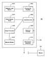
- FIG. 1is a front view of an embodiment of an optical code imaging system in accordance with the present invention
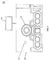
- FIG. 2is an exploded view of an embodiment of a scanner of the optical code imaging system shown in FIG. 1 ;
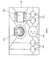
- FIG. 3is a back view of the scanner shown in FIG. 2 ;
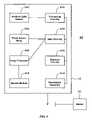
- FIG. 4is a block diagram of the optical code imaging system shown in FIG. 1 ;
- FIG. 5Ais a front view of an illumination assembly of the scanner shown in FIG. 2 ;
- FIG. 5Bis a side view of the illumination assembly shown in FIG. 5A .
- FIG. 1a front view of an exemplary optical code imaging system 10 is shown having a scanner 12 having first and second apertures 14 , 16 .
- the first aperture 14is associated with an ambient light sensor (not shown) described below with respect to FIGS. 2-6 .
- the second aperture 16is associated with a photo sensor array (not shown), described below with respect to FIGS. 2-3 .
- the scanner 12may be in wired or wireless communication with at least one device 20 , such as host terminal, other scanners, peripheral devices, etc.
- FIGS. 2 and 3show respective back and exploded views of the scanner 12 , where the scanner 12 is shown to further include an ambient light sensor 202 , a photo sensor array 204 , imaging optics 206 , and optionally an aiming assembly 208 for providing assistance in aiming the scanner 12 , and an illumination assembly 210 for providing illumination when performing an imaging operation.
- the ambient light sensor 202includes one or more photo sensors for sparsely sampling ambient light conditions.
- the photo sensors of the ambient light sensor 202sense light including the reflected light transmitted through the first aperture 14 .
- Optics, including one or more lenses,may optionally be provided for focusing ambient light transmitted through the first aperture 14 onto the ambient light sensor 202 .
- the photo sensors of the ambient light sensor 202are capable of sensing a range of light intensities and generating the at least one first electrical signal, which corresponds to the sensing and is indicative of the ambient light intensity.
- the ambient light sensor 202it is preferable for the ambient light sensor 202 to include a minimal number of sensors for minimizing processing, use of processing resources and processing time. Accordingly, it is preferable that the first electrical signal(s) is insufficient for generating a decodable image (i.e., an image that has sufficient information for being decoded by a decoding module for decoding optical codes).
- the first electrical signal(s)is processed for generating ambient light information in accordance with the sparse sampling, where the processing of the first electrical signal(s) for providing ambient lighting conditions may be performed entirely by analog components.
- the number of photo sensors in the ambient light sensorcorresponds to the number of samples acquired for sampling the ambient lighting conditions.
- the photo sensor array 204includes an array of photo sensors capable of sensing light reflected from objects lying within the field of view (FOV) of the scanner 400 , and of generating the plurality of second electrical signals which correspond to the sensing, where the FOV of the photo sensor array 204 defines the FOV of the scanner 200 .
- the photo sensors of the photo sensor array 204sense light, including the reflected light, transmitted through the second aperture 16 .
- the imaging optics 206includes one or more lenses for focusing the light transmitted through the second aperture 16 onto the photo sensor array 204 .
- the number of photo sensors in the photo sensor array 204corresponds to the number of pixels of information which describe the image generated by the scanning operation, which determines the resolution of the image. An ample number of photo sensors are provided for generating enough pixels for generation of a decodable image.
- the plurality of second electrical signalsare digitized for generating the image and for decoding thereof.
- the photo sensor array 204may be a CCD or other similar device.
- the illumination assembly 210includes one or more light sources, such as light emitting diodes (LEDs), xenon tubes or laser sources, for providing illumination during sensing by the photo sensor array 204 .
- the light sourcespreferably LEDs, are activated during a scan operation (i.e., image capture, including sensing and decode attempt), but preferably are not activated prior thereto, so as not to affect the ambient lighting conditions being sensed by the ambient light sensor 202 .
- the illumination assembly 210further includes circuitry for determining the intensity of the illumination provided, and duration of the illumination provided, such as in accordance with illumination settings, as described further below.
- the circuitry for determining the intensitymay include, for example, circuitry for selecting light source(s) that are enabled during an illumination operation from the at least one light source, and/or circuitry for determining the amount of current input to the one or more light sources.
- the circuitry for determining the durationmay include, for example, a counter and/or a timer.
- the FOV of the ambient light sensor 202may or may not coincide or overlay the FOV of the photo sensor array 204 .
- the relationship between the size of the ambient light sensor 202 , the size of the first aperture 14 , and the effective focal distance for the ambient light sensor 202is selected for optimizing coincidence of the FOV of the photo sensor array 204 and the ambient light sensor 202 .
- the optimizationis for avoiding saturation of the ambient light sensor at an extreme high illumination level while providing adequate sensitivity for light sensing at a low level of illumination.
- the ambient light sensor 202is included in photo sensor array 204 , where the photo sensor array 204 includes one or more photo sensors of the ambient light sensor 202 .
- the ambient light sensor 202 and the photo array sensor 204may be provided on the same circuit board.
- at least one of the photo sensors of at least one of the ambient light sensor 202 and/or the photo array sensor 204may be disabled when photo sensors of the other of the ambient light sensor 202 and the photo array sensor 204 are enabled.
- the number of photo sensors included in ambient light sensor 202is significantly less than the number of photo sensors included in the array of photo sensor array 204 .
- the photo sensors of the photo sensor array 204 that are not included in the ambient light sensor 202are “closed” (i.e., disabled) when a scan operation is not being performed.
- the sensorsmay be “closed”, such as by physically blocking light from striking the sensors, or by electronically blocking generation of electrical signals by the blocked sensors, transfer of the electrical signals, or processing of the electrical signals, such as digitizing, image processing and/or decoding thereof.
- the photo sensors included in the ambient light sensor 202may be dedicated to sensing ambient light only, and may be “closed” when a scan operation is being performed, or alternatively may be used for ambient light sensing as well as scan operations, or a combination thereof (where a portion of the photo sensors included in the ambient light sensor 202 are dedicated).
- the photo sensors included in the ambient light sensor 202may be distributed among the sensors of the photo sensor array 204 or may be positioned as a group, or a combination thereof. Furthermore, only one aperture may be provided for transmitting light to the ambient light sensor 202 and the photo array sensor 204 .
- FIG. 4a block diagram of the optical code imaging system 10 is shown, including the ambient light sensor 202 , the photo sensor array 204 , processing circuitry 402 , gain circuitry 404 , exposure circuitry 406 , the illumination assembly 210 , image processor 408 and decode module 410 .
- the components shown in FIG. 4are supported within a housing of the scanner 12 , such as a handheld scanner.
- the scanner 12may be in wired or wireless communication with device(s) 20 .
- the processing circuitry 402includes at least one of one or more analog components and at least one digital processor, such as a microprocessor.
- the digital processormay share some or all of its resources with the image processor 408 and/or the decode module 410 .
- the processing circuitry 402includes one or more analog comparators 412 for comparing a setting voltage of the at least one first electrical signal (individually or in combination) to a reference voltage and outputting a control signal indicative of the results of the compare operation.
- the control signalis provided to the gain circuitry 404 , the exposure circuitry 406 , and/or the illumination assembly 210 for controlling the respective parameter settings, i.e., the gain setting, the exposure setting (i.e., exposure time), and/or illumination setting (i.e., illumination intensity and/or illumination duration).
- the control signalis provided directly to the gain circuitry 404 , exposure circuitry 406 and/or illumination assembly 210 .
- the control signalmay be provided to the digital processor for processing thereof and outputting further control signals to the gain circuitry 404 , the exposure/circuitry 406 and/or the illumination assembly 210 .
- the at least one first electrical signalmay be digitized and processed by the digital processor for outputting the control signal to the gain circuitry 404 , the exposure circuitry 406 , and/or the illumination assembly 210 .
- the digital processormay be used for outputting the control signal to the gain circuitry 404 , the exposure circuitry 406 , and/or the illumination assembly 210 .
- a combination of the aforementioned methodsmay be used.
- the control signal output by the processing circuitryhas a frequency that corresponds to the level of light sensed by the ambient light sensor 202 .
- the processing circuitry 402processes the at least one first electrical signal to determine what level of ambient light has been sensed from at least two possible levels, and generates the control signal so that the frequency of the output control signal is selected to correspond to a frequency that is indicative of (i.e., assigned to correspond to, where a predetermined frequency is assigned to correspond to each possible level) the determined level.
- the gain circuitry 404includes circuitry such as gain amplifiers, as known in the art, for processing gain of signals provided.
- the gain circuitry 404may be integrated with the photo sensor array 204 or may be external to the photo sensor array 204 .
- the gain circuitry 404processes at least a portion of the plurality of second electronic signals generated by the photo sensor array 204 for processing gain thereof in accordance with the gain setting.
- the plurality of second electronic signalsare processed by other circuitry (not shown), such as for buffering, filtering and/or digitizing the plurality of second electronic signals for preparing the received plurality of second electronic signals for image processing by the image processor 408 and/or decoding by the decode module 410 .
- the other circuitrymay be provided for processing the plurality of second electronic signals before and/or after the gain circuitry 404 performs gain processing on the plurality of second electronic signals.
- the exposure circuitry 406controls the exposure time (i.e., integration time), and may include an electronic shutter and/or circuitry for controlling a mechanical shutter.
- the exposure circuitry 406may be integrated with the photo sensor array 204 or may be external to the photo sensor array 204 .
- the exposure circuitry 406controls opening of the shutter (electrical or mechanical) for an amount of time in accordance with the exposure setting, such as where the amount of time corresponds to a magnitude (such as voltage) of the received control signal.
- the image processor 408includes at least one processor for at least a portion of the plurality of second electronic signals, such as for generating a corresponding image, locating the optical code in the image and/or extracting data corresponding to the optical code.
- the decode module 410includes at least one processor for decoding the data corresponding to the optical code and generating decoded information.
- decoded information generated by the decode module 410is provided (e.g., displayed) to the user and/or provided to a host processor for further processing thereof, such as for processing a transaction, updating a database (e.g., inventory), etc.
- the at least one processor of the decode module 410 , the image processor 408 and the digital processor of the processing circuitry 402may partially or completely share the same resources.
- first and second apertures 14 , 16 and associated lensesare housed in one chassis.
- first and second apertures 14 , 16 and the at least one lensare housed in at least a first and second chassis. It is envisioned that the second aperture 16 and associated lens(es) is housed in the second chassis, and wherein the second chassis is removable from the first chassis. It is further envisioned that a scanner 12 having only a photo sensor array 204 may be outfitted with an additional chassis housing the ambient light sensor 202 , associated second aperture 16 and optionally associated lens(es).
- the scanner 12is provided with connections from the ambient light sensor 202 to the processing circuitry, and from the processing circuitry 402 to at least one of the gain circuitry 404 , the exposure circuitry 406 and the illumination assembly 210 for control thereof.
- the processing circuitry 402is updated with appropriate software, firmware and/or hardware to incorporate processing of the second ambient light signals and generation of the desired control signals.
- ambient lightenters the scanner via the first aperture 14 .
- the ambient lightis sensed by the ambient light sensor 202 , which generates one or more first electrical signals corresponding to the sensing and which is indicative of ambient lighting conditions (intensity).
- the first electrical signalis processed by processing circuitry 402 , which determines, in accordance with the processing, a desired setting for controlling at least one of the gain circuitry 404 , the exposure circuitry 406 , and the illumination assembly 210 .
- the first electrical signalcorresponds to a sampling of ambient light conditions associated with one or more points in the FOV of the ambient light sensor 202 .
- the processing circuitry 402controls at least one of the gain circuitry 404 , the exposure circuitry 406 , and the illumination assembly 210 for setting parameters such as gain of the gain circuitry 404 , exposure time (integration time) of the exposure circuitry 406 , illumination intensity of illumination generated by the illumination assembly 210 and/or duration of illumination generated by the illumination assembly 210 in accordance with the corresponding desired settings.
- a scan operationis performed where the illumination assembly 210 is activated for providing illumination in accordance with the illumination intensity and/or illumination duration settings, light reflected from objects within the FOV of the scanner (e.g., a target being imaged) is exposed to the photo sensor array 204 and sensed by the photo sensor array 204 , wherein the exposing is performed in accordance with exposure time setting for the exposure circuitry 406 .
- the photo sensor array 204generates a plurality (an array) of second electrical signals corresponding to the sensing, which further correspond to a two-dimensional array of pixel information for forming an image.
- At least a portion of the plurality of second electrical signalsare processed for preparing them for digital processing, including amplification thereof with the gain circuitry 404 in accordance with the gain setting, and digitization thereof. At least a portion of the digitized signals are then processed by the image processor 408 and/or the decode module 410 for generating an image and decoding the optical code in the image.
- the imageincludes sufficient data for processing by the decoder module 410 , so that when the optical code is properly imaged the decoder module 410 can successfully decode the image.
- the ambient light sensor 202operates continuously, where the first electric signal is processed continually, and the gain circuitry 404 , the exposure circuitry 406 , and/or the illumination assembly 210 is controlled continuously (in real time) in accordance with the continually processed first electric signal. Accordingly, the gain, exposure time, illumination intensity and/or illumination duration are set in accordance with the ambient light conditions at any given time, so that when a scan operation is commenced the appropriate gain, exposure time, illumination intensity and/or illumination duration settings are used.
- Processing time and resourcesare minimized for processing of the first electrical signal generated by the ambient light sensor 202 for adjusting the appropriate gain, exposure, and/or illumination settings.
- the processing time for the aboveis under 1 msec. On the contrary, it takes on the order of tens of milliseconds (typically 33 milliseconds) to process the plurality of second electrical signals generated by the photo array sensor 204 .
- the gain circuitry 404 , the exposure circuitry 406 , and/or the illumination assembly 210are set in accordance with the first electric signal upon commencing a scan operation, such as upon activation of a trigger by a user. Accordingly, the gain circuitry 404 , the exposure circuitry 406 , and/or the illumination assembly 210 are adjusted only upon activation of a scan operation with settings that were already determined during the continual processing of the plurality of second electrical signals.
- the ambient light sensor 202by using the ambient light sensor 202 and processing the first electrical signals for determining the ambient light conditions for setting the gain, exposure and/or illumination settings, a significant amount of processing resources and time are saved, as opposed to the amount of processing resources and time that is commonly used for determining the ambient light conditions from the plurality of second signals generated by the photo array sensor 204 .
- the ambient light sensor 202is positioned in the same plane as light sources (e.g., LEDs) 502 of the illumination assembly 210 , so that the ambient light sensor 202 has substantially the same view of the object being imaged as the illumination assembly and for obtaining a precise measurement to the ambient light incident on the object.
- Photo sensors 504 of the ambient light sensor 202are shown mounted on a support 506 for the LEDs 502 of the illumination assembly, so that the photo sensors 504 are positioned in the same plane as the LEDs 502 .
Landscapes
- Physics & Mathematics (AREA)
- Electromagnetism (AREA)
- Engineering & Computer Science (AREA)
- Health & Medical Sciences (AREA)
- General Health & Medical Sciences (AREA)
- Toxicology (AREA)
- Artificial Intelligence (AREA)
- Computer Vision & Pattern Recognition (AREA)
- General Physics & Mathematics (AREA)
- Theoretical Computer Science (AREA)
- Image Input (AREA)
- Facsimile Scanning Arrangements (AREA)
Abstract
Description
Claims (35)
Priority Applications (1)
| Application Number | Priority Date | Filing Date | Title |
|---|---|---|---|
| US10/803,669US7303126B2 (en) | 2004-03-18 | 2004-03-18 | System and method for sensing ambient light in an optical code reader |
Applications Claiming Priority (1)
| Application Number | Priority Date | Filing Date | Title |
|---|---|---|---|
| US10/803,669US7303126B2 (en) | 2004-03-18 | 2004-03-18 | System and method for sensing ambient light in an optical code reader |
Publications (2)
| Publication Number | Publication Date |
|---|---|
| US20050205677A1 US20050205677A1 (en) | 2005-09-22 |
| US7303126B2true US7303126B2 (en) | 2007-12-04 |
Family
ID=34985190
Family Applications (1)
| Application Number | Title | Priority Date | Filing Date |
|---|---|---|---|
| US10/803,669Expired - LifetimeUS7303126B2 (en) | 2004-03-18 | 2004-03-18 | System and method for sensing ambient light in an optical code reader |
Country Status (1)
| Country | Link |
|---|---|
| US (1) | US7303126B2 (en) |
Cited By (35)
| Publication number | Priority date | Publication date | Assignee | Title |
|---|---|---|---|---|
| US20060256197A1 (en)* | 2005-05-11 | 2006-11-16 | Fultz William W | Method of operation for a vision-based occupant sensing system |
| US20070051812A1 (en)* | 2005-08-24 | 2007-03-08 | Intermec Ip Corp. | Method and apparatus employing imaging and/or scanning for reading machine-readable symbols such as barcode symbols |
| US20070199998A1 (en)* | 2003-11-13 | 2007-08-30 | Anatoly Kotlarsky | Method of dynamically controlling illumination and image capturing operations in a digital image capture and processing system |
| US20070210166A1 (en)* | 2000-11-24 | 2007-09-13 | Knowles C H | Omni-directional digital image capturing and processing system comprising coplanar illumination and imaging stations automatically detecting object motion and velocity and adjusting exposure and/or illumination control parameters therewithin |
| US20080283608A1 (en)* | 2003-11-13 | 2008-11-20 | Metrologic Instruments, Inc. | Method of illuminating objects on a countertop surface using an automatically-triggered digital image capture and processing system which maintains illumination rays substantially within the field of view (FOV) of said system, above which the field of view (FOV) of human operator and spectating customers are positioned |
| US20080283611A1 (en)* | 2000-11-24 | 2008-11-20 | Metrologic Instruments, Inc. | Digital image capture and processing systems for supporting 3D imaging volumes in retail point-of-sale environments |
| US7503498B2 (en) | 2003-11-13 | 2009-03-17 | Metrologic Instruments, Inc. | Hand-supportable digital image capturing and processing system employing an area-type image sensing array exposed to illumination from an LED-based illumination array only when all sensor elements in said image-sensing array are activated and in a state of integration |
| US20090072038A1 (en)* | 2007-06-04 | 2009-03-19 | Hand Held Products, Inc. | Indicia reading terminal having multiple setting imaging lens |
| US7568628B2 (en) | 2005-03-11 | 2009-08-04 | Hand Held Products, Inc. | Bar code reading device with global electronic shutter control |
| US7594609B2 (en) | 2003-11-13 | 2009-09-29 | Metrologic Instruments, Inc. | Automatic digital video image capture and processing system supporting image-processing based code symbol reading during a pass-through mode of system operation at a retail point of sale (POS) station |
| US7611060B2 (en) | 2005-03-11 | 2009-11-03 | Hand Held Products, Inc. | System and method to automatically focus an image reader |
| US7735731B2 (en) | 2007-01-17 | 2010-06-15 | Metrologic Instruments, Inc. | Web-enabled mobile image capturing and processing (MICAP) cell-phone |
| US20100155486A1 (en)* | 2008-12-18 | 2010-06-24 | Symbol Technologies, Inc. | Adaptive optimizations for signal processing in imaging readers |
| US7770799B2 (en) | 2005-06-03 | 2010-08-10 | Hand Held Products, Inc. | Optical reader having reduced specular reflection read failures |
| US7780089B2 (en) | 2005-06-03 | 2010-08-24 | Hand Held Products, Inc. | Digital picture taking optical reader having hybrid monochrome and color image sensor array |
| WO2012093963A1 (en)* | 2011-01-04 | 2012-07-12 | Piqx Imaging Pte Ltd | Scanning method and apparatus |
| US8387881B2 (en) | 2010-12-01 | 2013-03-05 | Hand Held Products, Inc. | Terminal with screen reading mode |
| US8537245B2 (en) | 2011-03-04 | 2013-09-17 | Hand Held Products, Inc. | Imaging and decoding device with quantum dot imager |
| US8561903B2 (en) | 2011-01-31 | 2013-10-22 | Hand Held Products, Inc. | System operative to adaptively select an image sensor for decodable indicia reading |
| US8596542B2 (en) | 2002-06-04 | 2013-12-03 | Hand Held Products, Inc. | Apparatus operative for capture of image data |
| US8608071B2 (en) | 2011-10-17 | 2013-12-17 | Honeywell Scanning And Mobility | Optical indicia reading terminal with two image sensors |
| US8628013B2 (en) | 2011-12-13 | 2014-01-14 | Honeywell International Inc. | Apparatus comprising image sensor array and illumination control |
| US8629926B2 (en) | 2011-11-04 | 2014-01-14 | Honeywell International, Inc. | Imaging apparatus comprising image sensor array having shared global shutter circuitry |
| US8636215B2 (en) | 2011-06-27 | 2014-01-28 | Hand Held Products, Inc. | Decodable indicia reading terminal with optical filter |
| US8640958B2 (en) | 2010-01-21 | 2014-02-04 | Honeywell International, Inc. | Indicia reading terminal including optical filter |
| US8640960B2 (en) | 2011-06-27 | 2014-02-04 | Honeywell International Inc. | Optical filter for image and barcode scanning |
| US8646692B2 (en) | 2011-09-30 | 2014-02-11 | Hand Held Products, Inc. | Devices and methods employing dual target auto exposure |
| US20140183263A1 (en)* | 2013-01-03 | 2014-07-03 | Symbol Technologies, Inc. | Method of controlling illumination pulses to increase dynamic range in bioptic imager barcode scanner |
| US8777108B2 (en) | 2012-03-23 | 2014-07-15 | Honeywell International, Inc. | Cell phone reading mode using image timer |
| US8881983B2 (en) | 2011-12-13 | 2014-11-11 | Honeywell International Inc. | Optical readers and methods employing polarization sensing of light from decodable indicia |
| US8978981B2 (en) | 2012-06-27 | 2015-03-17 | Honeywell International Inc. | Imaging apparatus having imaging lens |
| US8985459B2 (en) | 2011-06-30 | 2015-03-24 | Metrologic Instruments, Inc. | Decodable indicia reading terminal with combined illumination |
| US9361502B2 (en) | 2014-07-31 | 2016-06-07 | Symbol Technologies, Llc | System for, and method of, controlling target illumination for an imaging reader |
| US9418270B2 (en) | 2011-01-31 | 2016-08-16 | Hand Held Products, Inc. | Terminal with flicker-corrected aimer and alternating illumination |
| US10311424B2 (en) | 2010-12-09 | 2019-06-04 | Hand Held Products, Inc. | Indicia encoding system with integrated purchase and payment information |
Families Citing this family (10)
| Publication number | Priority date | Publication date | Assignee | Title |
|---|---|---|---|---|
| US20050249390A1 (en)* | 2004-04-29 | 2005-11-10 | Mcclurg George W | Method and apparatus for discriminating ambient light in a fingerprint scanner |
| US7490770B2 (en)* | 2004-08-12 | 2009-02-17 | Datalogic Scanning, Inc. | System and method of optical reading with enhanced depth of field collection |
| US7380721B2 (en)* | 2006-08-22 | 2008-06-03 | Honeywell International Inc. | Low-cost compact bar code sensor |
| US7978477B2 (en)* | 2008-05-09 | 2011-07-12 | Avago Technologies Ecbu Ip (Singapore) Pte. Ltd. | Dual-channel optical navigation device |
| US8408464B2 (en)* | 2011-02-03 | 2013-04-02 | Metrologic Instruments, Inc. | Auto-exposure method using continuous video frames under controlled illumination |
| US9521331B2 (en)* | 2015-04-21 | 2016-12-13 | Hand Held Products, Inc. | Capturing a graphic information presentation |
| FR3069685B1 (en) | 2017-07-26 | 2019-08-16 | Jes Labs | INSTALLATION AND METHOD FOR MANAGING PRODUCT DATA |
| EP3529785B1 (en)* | 2016-10-20 | 2023-11-29 | Jes | System for identifying or assisting the identification of a product or set of products |
| US11829982B2 (en)* | 2019-04-15 | 2023-11-28 | Jes Labs | System for identifying or assisting the identification of a product or set of products |
| JP7408300B2 (en)* | 2019-06-04 | 2024-01-05 | 東芝テック株式会社 | Store management device, electronic receipt system and control program |
Citations (14)
| Publication number | Priority date | Publication date | Assignee | Title |
|---|---|---|---|---|
| US4818856A (en)* | 1985-11-06 | 1989-04-04 | Nippondenso Co., Ltd. | Optical information reading apparatus |
| US5189464A (en)* | 1991-12-18 | 1993-02-23 | Polaroid Corporation | Supplemental lens positioning system for a fixed focus lens camera |
| US5672858A (en)* | 1994-06-30 | 1997-09-30 | Symbol Technologies Inc. | Apparatus and method for reading indicia using charge coupled device and scanning laser beam technology |
| US5742340A (en)* | 1995-06-06 | 1998-04-21 | Hughes Missile Systems Company | Ambient light automatic gain control for electronic imaging cameras and the like |
| US5801371A (en) | 1995-03-20 | 1998-09-01 | Symbol Technologies, Inc. | Optical reader with independent triggering and graphical user interface |
| US5955720A (en) | 1996-03-21 | 1999-09-21 | Symbol Technologies, Inc. | Semi-retroreflective scanners |
| US6340114B1 (en) | 1998-06-12 | 2002-01-22 | Symbol Technologies, Inc. | Imaging engine and method for code readers |
| US6385352B1 (en)* | 1994-10-26 | 2002-05-07 | Symbol Technologies, Inc. | System and method for reading and comparing two-dimensional images |
| US6634558B1 (en) | 1998-08-12 | 2003-10-21 | Symbol Technologies, Inc. | Optical code reader with hand mounted imager |
| US6685092B2 (en) | 2001-06-15 | 2004-02-03 | Symbol Technologies, Inc. | Molded imager optical package and miniaturized linear sensor-based code reading engines |
| US6695209B1 (en)* | 1999-10-04 | 2004-02-24 | Psc Scanning, Inc. | Triggerless optical reader with signal enhancement features |
| US6708883B2 (en)* | 1994-06-30 | 2004-03-23 | Symbol Technologies, Inc. | Apparatus and method for reading indicia using charge coupled device and scanning laser beam technology |
| US6729546B2 (en)* | 1994-10-26 | 2004-05-04 | Symbol Technologies, Inc. | System for reading two-dimensional images using ambient and/or projected light |
| US7021542B2 (en)* | 2003-08-01 | 2006-04-04 | Symbol Technologies, Inc. | Imaging and illumination engine for an optical code reader |
Family Cites Families (1)
| Publication number | Priority date | Publication date | Assignee | Title |
|---|---|---|---|---|
| JPH07183618A (en)* | 1993-12-22 | 1995-07-21 | Ricoh Co Ltd | Semiconductor laser device, semiconductor laser device manufacturing method, and integrated semiconductor laser device |
- 2004
- 2004-03-18USUS10/803,669patent/US7303126B2/ennot_activeExpired - Lifetime
Patent Citations (15)
| Publication number | Priority date | Publication date | Assignee | Title |
|---|---|---|---|---|
| US4818856A (en)* | 1985-11-06 | 1989-04-04 | Nippondenso Co., Ltd. | Optical information reading apparatus |
| US5189464A (en)* | 1991-12-18 | 1993-02-23 | Polaroid Corporation | Supplemental lens positioning system for a fixed focus lens camera |
| US6708883B2 (en)* | 1994-06-30 | 2004-03-23 | Symbol Technologies, Inc. | Apparatus and method for reading indicia using charge coupled device and scanning laser beam technology |
| US5672858A (en)* | 1994-06-30 | 1997-09-30 | Symbol Technologies Inc. | Apparatus and method for reading indicia using charge coupled device and scanning laser beam technology |
| US6398112B1 (en)* | 1994-06-30 | 2002-06-04 | Symbol Technologies, Inc. | Apparatus and method for reading indicia using charge coupled device and scanning laser beam technology |
| US6385352B1 (en)* | 1994-10-26 | 2002-05-07 | Symbol Technologies, Inc. | System and method for reading and comparing two-dimensional images |
| US6729546B2 (en)* | 1994-10-26 | 2004-05-04 | Symbol Technologies, Inc. | System for reading two-dimensional images using ambient and/or projected light |
| US5801371A (en) | 1995-03-20 | 1998-09-01 | Symbol Technologies, Inc. | Optical reader with independent triggering and graphical user interface |
| US5742340A (en)* | 1995-06-06 | 1998-04-21 | Hughes Missile Systems Company | Ambient light automatic gain control for electronic imaging cameras and the like |
| US5955720A (en) | 1996-03-21 | 1999-09-21 | Symbol Technologies, Inc. | Semi-retroreflective scanners |
| US6340114B1 (en) | 1998-06-12 | 2002-01-22 | Symbol Technologies, Inc. | Imaging engine and method for code readers |
| US6634558B1 (en) | 1998-08-12 | 2003-10-21 | Symbol Technologies, Inc. | Optical code reader with hand mounted imager |
| US6695209B1 (en)* | 1999-10-04 | 2004-02-24 | Psc Scanning, Inc. | Triggerless optical reader with signal enhancement features |
| US6685092B2 (en) | 2001-06-15 | 2004-02-03 | Symbol Technologies, Inc. | Molded imager optical package and miniaturized linear sensor-based code reading engines |
| US7021542B2 (en)* | 2003-08-01 | 2006-04-04 | Symbol Technologies, Inc. | Imaging and illumination engine for an optical code reader |
Cited By (182)
| Publication number | Priority date | Publication date | Assignee | Title |
|---|---|---|---|---|
| US7762465B2 (en) | 2000-11-24 | 2010-07-27 | Metrologic Instruments, Inc. | Device for optically multiplexing a laser beam |
| US20070210166A1 (en)* | 2000-11-24 | 2007-09-13 | Knowles C H | Omni-directional digital image capturing and processing system comprising coplanar illumination and imaging stations automatically detecting object motion and velocity and adjusting exposure and/or illumination control parameters therewithin |
| US20070257114A1 (en)* | 2000-11-24 | 2007-11-08 | Knowles C H | Automatic omnidirectional bar code symbol reading system employing linear-type and area-type bar code symbol reading stations within the system housing |
| US20070262153A1 (en)* | 2000-11-24 | 2007-11-15 | Knowles C H | Digital image capturing and processing system for producing and projecting a complex of coplanar illumination and imaging planes into a 3D imaging volume and controlling illumination control parameters in said system using the detected motion and velocity of objects present therewithin |
| US20070262150A1 (en)* | 2000-11-24 | 2007-11-15 | Knowles C H | Digital image capturing and processing system employing a plurality of coplanar illuminating and imaging stations projecting a plurality of coplanar illumination and imaging planes into a 3D imaging volume, and controlling operations therewithin using control data derived from motion data collected from the automated detection of objects passing through said 3D imaging volume |
| US20070278308A1 (en)* | 2000-11-24 | 2007-12-06 | Metrologic Instruments, Inc. | Digital image capturing and processing system employing a plurality of coplanar illumination and imaging subsystems for digitally imaging objects in a 3D imaging volume, and a globally-deployed object motion detection subsystem for automatically detecting and analyzing the motion of object passing through said 3D imaging volume |
| US20080000982A1 (en)* | 2000-11-24 | 2008-01-03 | Knowles C H | Automatic POS-based digital image capturing and processing system employing object motion controlled area-type illumination and imaging operations |
| US20080029600A1 (en)* | 2000-11-24 | 2008-02-07 | Metrologic Instruments, Inc. | Digital-imaging based code symbol reading system employing a plurality of coplanar illumination and imaging subsystems, each having a local object motion detection subsystem for automatic detecting objects within the 3D imaging volume, and a local control subsystem for transmitting object detection state data to a global control subsystem for managing the state of operation of said coplanar illumination and imaging subsystems |
| US8172141B2 (en) | 2000-11-24 | 2012-05-08 | Metrologic Instruments, Inc. | Laser beam despeckling devices |
| US20080283611A1 (en)* | 2000-11-24 | 2008-11-20 | Metrologic Instruments, Inc. | Digital image capture and processing systems for supporting 3D imaging volumes in retail point-of-sale environments |
| US8042740B2 (en) | 2000-11-24 | 2011-10-25 | Metrologic Instruments, Inc. | Method of reading bar code symbols on objects at a point-of-sale station by passing said objects through a complex of stationary coplanar illumination and imaging planes projected into a 3D imaging volume |
| US7905413B2 (en) | 2000-11-24 | 2011-03-15 | Metrologic Instruments, Inc. | Digital image capturing and processing system employing a plurality of coplanar illumination and imaging subsystems for digitally imaging objects in a 3D imaging volume, and a globally-deployed object motion detection subsystem for automatically detecting and analyzing the motion of objects passing through said 3-D imaging volume |
| US7878407B2 (en) | 2000-11-24 | 2011-02-01 | Metrologic Instruments, Inc. | POS-based digital image capturing and processing system employing automatic object motion detection and spectral-mixing based illumination techniques |
| US7806335B2 (en) | 2000-11-24 | 2010-10-05 | Metrologic Instruments, Inc. | Digital image capturing and processing system for automatically recognizing objects in a POS environment |
| US7516898B2 (en) | 2000-11-24 | 2009-04-14 | Metrologic Instruments, Inc. | Digital image capturing and processing system for producing and projecting a complex of coplanar illumination and imaging planes into a 3D imaging volume and controlling illumination control parameters in said system using the detected motion and velocity of object |
| US7520433B2 (en) | 2000-11-24 | 2009-04-21 | Metrologic Instruments, Inc. | Method for intelligently controlling the illumination and imagine of objects as they are moved through the 3D imaging volume of a digital image capturing and processing system |
| US7527204B2 (en) | 2000-11-24 | 2009-05-05 | Metrologic Instruments, Inc. | Omni-directional digital image capturing and processing system comprising coplanar illumination and imaging stations automatically detecting object motion and velocity and adjusting exposure and/or illumination control parameters therewithin |
| US7533820B2 (en) | 2000-11-24 | 2009-05-19 | Metrologic Instruments, Inc. | Digital image capturing and processing system employing coplanar illumination and imaging stations which generate coplanar illumination and imaging planes only when and where an object is being moved within the 3D imaging volume |
| US7533823B2 (en) | 2000-11-24 | 2009-05-19 | Metrologic Instruments, Inc. | Digital image capturing and processing system employing a plurality of coplanar illuminating and imaging stations projecting a plurality of coplanar illumination and imaging planes into a 3D imaging volume, and controlling operations therewithin using control data derived from motion data collected from the automated detection of objects passing through said 3D imaging volume |
| US7537165B2 (en) | 2000-11-24 | 2009-05-26 | Metrologic Instruments, Inc. | Omni-directional digital image capturing and processing system employing coplanar illumination and imaging planes and area-type illumination and imaging zones within the system housing |
| US7540424B2 (en) | 2000-11-24 | 2009-06-02 | Metrologic Instruments, Inc. | Compact bar code symbol reading system employing a complex of coplanar illumination and imaging stations for omni-directional imaging of objects within a 3D imaging volume |
| US7806336B2 (en) | 2000-11-24 | 2010-10-05 | Metrologic Instruments, Inc. | Laser beam generation system employing a laser diode and high-frequency modulation circuitry mounted on a flexible circuit |
| US7540422B2 (en) | 2000-11-24 | 2009-06-02 | Metrologic Instruments, Inc. | Digital image capturing and processing system employing imaging window protection plate having an aperture pattern and being disposed over said imaging window and beneath which resides a plurality of coplanar illumination and imaging stations |
| US7543749B2 (en) | 2000-11-24 | 2009-06-09 | Metrologic Instruments, Inc. | Digital image capturing and processing system having a plurality of coplanar illumination and imaging subsystems, each employing a dual-type coplanar linear illumination and imaging engine that supports image-processing based object motion and velocity detection, and automatic image formation and detection along the coplanar illumination and imaging plane produced thereby |
| US7546952B2 (en) | 2000-11-24 | 2009-06-16 | Metrologic Instruments, Inc. | Method of illuminating objects during digital image capture operations by mixing visible and invisible spectral illumination energy at point of sale (POS) environments |
| US7556199B2 (en) | 2000-11-24 | 2009-07-07 | Metrologic Instruments, Inc. | Digital image capturing and processing system employing a plurality of coplanar illuminating and imaging stations projecting a complex of coplanar illumination and imaging planes into a 3D imaging volume so as to support pass-through and presentation modes of digital imaging at a point of sale (POS) environment |
| US7559474B2 (en) | 2000-11-24 | 2009-07-14 | Metrologic Instruments, Inc. | Automatic omnidirectional bar code symbol reading system employing linear-type and area-type bar code symbol reading stations within the system housing |
| US7793841B2 (en) | 2000-11-24 | 2010-09-14 | Metrologic Instruments, Inc. | Laser illumination beam generation system employing despeckling of the laser beam using high-frequency modulation of the laser diode current and optical multiplexing of the component laser beams |
| US7784695B2 (en) | 2000-11-24 | 2010-08-31 | Metrologic Instruments, Inc. | Planar laser illumination module (PLIM) employing high-frequency modulation (HFM) of the laser drive currents and optical multplexing of the output laser beams |
| US7568626B2 (en) | 2000-11-24 | 2009-08-04 | Metrologic Instruments, Inc. | Automatic POS-based digital image capturing and processing system employing a plurality of area-type illumination and imaging zones intersecting within the 3D imaging volume of the system |
| US7571858B2 (en) | 2000-11-24 | 2009-08-11 | Metrologic Instruemtns, Inc. | POS-based digital image capturing and processing system using automatic object detection, spectral-mixing based illumination and linear imaging techniques |
| US7571859B2 (en) | 2000-11-24 | 2009-08-11 | Metrologic Instruments, Inc. | Digital-imaging based code symbol reading system employing a plurality of coplanar illumination and imaging subsystems, global object motion detection subsystem for automatically detecting objects within its 3D imaging volume, and global control subsystem for managing the state of operation of said coplanar illumination and imaging substems |
| US7575169B2 (en) | 2000-11-24 | 2009-08-18 | Metrologic Instruments, Inc. | Digital image capturing and processing system for producing and projecting a plurality of coextensive area-type illumination and imaging zones into a 3D imaging volume and controlling illumination control parameters in said system using the detected motion of objects present therewithin |
| US7575170B2 (en) | 2000-11-24 | 2009-08-18 | Metrologic Instruments, Inc. | POS-based digital image capturing and processing system using automatic object detection, spectral-mixing based illumination and linear imaging techniques |
| US7578445B2 (en) | 2000-11-24 | 2009-08-25 | Metrologic Instruments, Inc. | Automatic POS-based digital image capturing and processing system employing object motion controlled area-type illumination and imaging operations |
| US7578442B2 (en) | 2000-11-24 | 2009-08-25 | Metrologic Instruments, Inc. | Method of and apparatus for identifying consumer products in a retail environment when bar code symbols on the products are not readable or have been removed from packaging |
| US7581680B2 (en) | 2000-11-24 | 2009-09-01 | Metrologic Instruments, Inc. | Omni-directional digital image capturing and processing system employing coplanar illumination and imaging stations in horizontal and vertical housing sections of the system |
| US7584892B2 (en) | 2000-11-24 | 2009-09-08 | Metrologic Instruments, Inc. | Digital-imaging based code symbol reading system employing a plurality of coplanar illumination and imaging subsystems, each having a local object motion detection subsystem for automatic detecting objects within the 3D imaging volume, and a local control subsystem for transmitting object detection state data to a global control subsystem for managing the state of operation of said coplanar illumination and imaging subsystems |
| US7588188B2 (en) | 2000-11-24 | 2009-09-15 | Metrologic Instruments, Inc. | Pos-based digital image capturing and processing system using automatic object detection, spectral-mixing based illumination and linear imaging techniques |
| US7594608B2 (en) | 2000-11-24 | 2009-09-29 | Metrologic Instruments, Inc. | Automatic omnidirectional bar code symbol reading system employing linear-type and area-type bar code symbol reading stations within the system housing |
| US7775436B2 (en) | 2000-11-24 | 2010-08-17 | Metrologic Instruments, Inc. | Method of driving a plurality of visible and invisible LEDs so as to produce an illumination beam having a dynamically managed ratio of visible to invisible (IR) spectral energy/power during object illumination and imaging operations |
| US7611062B2 (en) | 2000-11-24 | 2009-11-03 | Metrologic Instruments, Inc. | Omni-directional digital image capturing and processing system employing coplanar illumination and imaging planes and area-type illumination and imaging zones with the horizontal and vertical sections of the system housing |
| US7770796B2 (en) | 2000-11-24 | 2010-08-10 | Metrologic Instruments, Inc. | Device for producing a laser beam of reduced coherency using high-frequency modulation of the laser diode current and optical multiplexing of the output laser beam |
| US7614560B2 (en) | 2000-11-24 | 2009-11-10 | Metrologic Instruments, Inc. | Method of illuminating objects at a point of sale (POS) station by adaptively controlling the spectral composition of the wide-area illumination beam produced from an illumination subsystem within an automatic digital image capture and processing system |
| US7658330B2 (en) | 2000-11-24 | 2010-02-09 | Metrologic Instruments, Inc. | Automatic POS-based digital image capturing and processing system employing object motion controlled area-type illumination and imaging operations |
| US7661595B2 (en) | 2000-11-24 | 2010-02-16 | Metrologic Instruments, Inc. | Digital image capturing and processing system employing a plurality of area-type illuminating and imaging stations projecting a plurality of coextensive area-type illumination and imaging zones into a 3D imaging volume, and controlling operations therewithin using |
| US7661597B2 (en) | 2000-11-24 | 2010-02-16 | Metrologic Instruments, Inc. | Coplanar laser illumination and imaging subsystem employing spectral-mixing and despeckling of laser illumination |
| US7665665B2 (en) | 2000-11-24 | 2010-02-23 | Metrologic Instruments, Inc. | Digital illumination and imaging subsystem employing despeckling mechanism employing high-frequency modulation of laser diode drive current and optical beam multiplexing techniques |
| US7673802B2 (en) | 2000-11-24 | 2010-03-09 | Metrologic Instruments, Inc. | Automatic POS-based digital image capturing and processing system employing a plurality of area-type illumination and imaging zones intersecting within the 3D imaging volume of the system |
| US7731091B2 (en) | 2000-11-24 | 2010-06-08 | Metrologic Instruments, Inc. | Digital image capturing and processing system employing automatic object detection and spectral-mixing based illumination techniques |
| US9224023B2 (en) | 2002-06-04 | 2015-12-29 | Hand Held Products, Inc. | Apparatus operative for capture of image data |
| US8596542B2 (en) | 2002-06-04 | 2013-12-03 | Hand Held Products, Inc. | Apparatus operative for capture of image data |
| US8047438B2 (en) | 2003-11-13 | 2011-11-01 | Metrologic Instruments, Inc. | Digital image capture and processing system employing an image formation and detection subsystem having an area-type image detection array supporting periodic occurrance of snap-shot type image acquisition cycles at a high-repetition rate during object illumination |
| US7922089B2 (en) | 2003-11-13 | 2011-04-12 | Metrologic Instruments, Inc. | Hand-supportable digital image capture and processing system employing automatic object presence detection to control automatic generation of a linear targeting illumination beam within the field of view (FOV), and manual trigger switching to initiate illumination |
| US9104930B2 (en) | 2003-11-13 | 2015-08-11 | Metrologic Instruments, Inc. | Code symbol reading system |
| US20070199998A1 (en)* | 2003-11-13 | 2007-08-30 | Anatoly Kotlarsky | Method of dynamically controlling illumination and image capturing operations in a digital image capture and processing system |
| US8317105B2 (en) | 2003-11-13 | 2012-11-27 | Metrologic Instruments, Inc. | Optical scanning system having an extended programming mode and method of unlocking restricted extended classes of features and functionalities embodied therewithin |
| US20080283608A1 (en)* | 2003-11-13 | 2008-11-20 | Metrologic Instruments, Inc. | Method of illuminating objects on a countertop surface using an automatically-triggered digital image capture and processing system which maintains illumination rays substantially within the field of view (FOV) of said system, above which the field of view (FOV) of human operator and spectating customers are positioned |
| US8157175B2 (en) | 2003-11-13 | 2012-04-17 | Metrologic Instruments, Inc. | Digital image capture and processing system supporting a presentation mode of system operation which employs a combination of video and snapshot modes of image detection array operation during a single cycle of system operation |
| US7594609B2 (en) | 2003-11-13 | 2009-09-29 | Metrologic Instruments, Inc. | Automatic digital video image capture and processing system supporting image-processing based code symbol reading during a pass-through mode of system operation at a retail point of sale (POS) station |
| US8157174B2 (en) | 2003-11-13 | 2012-04-17 | Metrologic Instruments, Inc. | Digital image capture and processing system employing an image formation and detection system having an area-type image detection array supporting single snap-shot and periodic snap-shot modes of image acquisition during object illumination and imaging operations |
| US8132731B2 (en) | 2003-11-13 | 2012-03-13 | Metrologic Instruments, Inc. | Digital image capture and processing system having a printed circuit (PC) board with a light transmission aperture, wherein an image detection array is mounted on the rear side of said PC board, and a linear array of light emitting diodes (LEDS) is mounted on the front surface of said PC board, and aligned with an illumination-focusing lens structure integrated within said imaging window |
| US8100331B2 (en) | 2003-11-13 | 2012-01-24 | Metrologic Instruments, Inc. | Digital image capture and processing system having a printed circuit (PC) board with light transmission aperture, wherein first and second field of view (FOV) folding mirrors project the FOV of a digital image detection array on the rear surface of said PC board, through said light transmission aperture |
| US8087588B2 (en) | 2003-11-13 | 2012-01-03 | Metrologic Instruments, Inc. | Digital image capture and processing system having a single printed circuit (PC) board with a light transmission aperture, wherein a first linear array of visible light emitting diodes (LEDs) are mounted on the rear side of the PC board for producing a linear targeting illumination beam, and wherein a second linear array of visible LEDs are mounted on the front side of said PC board for producing a field of visible illumination within the field of view (FOV) of the system |
| US7559475B2 (en) | 2003-11-13 | 2009-07-14 | Metrologic Instruments, Inc. | Automatic digital-imaging based bar code symbol reading system supporting a pass-through mode of system operation using automatic object direction detection and illumination control, and video image capture and processing techniques |
| US8052057B2 (en) | 2003-11-13 | 2011-11-08 | Metrologic Instruments, Inc. | Method of programming the system configuration parameters of a digital image capture and processing system during the implementation of its communication interface with a host system without reading programming-type bar code symbols |
| US7540425B2 (en) | 2003-11-13 | 2009-06-02 | Metrologic Instruments, Inc. | Method of dynamically controlling illumination and image capturing operations in a digital image capture and processing system |
| US20080314987A1 (en)* | 2003-11-13 | 2008-12-25 | Metrologic Instruments, Inc. | Digital image capture and processing system having a printed circuit (PC) board with a light transmission aperture, wherein an image detection array is mounted on the rear side of said PC board, and a linear array of light emitting diodes (LEDS) is mounted on the front surface of said PC board, and aligned with an illumination-focusing lens structure integrated within said imaging window |
| US8011585B2 (en) | 2003-11-13 | 2011-09-06 | Metrologic Instruments, Inc. | Digital image capture and processing system employing a linear LED-based illumination array mounted behind an illumination-focusing lens component integrated within the imaging window of the system |
| US7997489B2 (en) | 2003-11-13 | 2011-08-16 | Metrologic Instruments, Inc. | Countertop-based digital image capture and processing system having an illumination subsystem employing a single array of LEDs disposed behind an illumination focusing lens structure integrated within the imaging window, for generating a field of visible illumination highly confined below the field |
| US7841533B2 (en) | 2003-11-13 | 2010-11-30 | Metrologic Instruments, Inc. | Method of capturing and processing digital images of an object within the field of view (FOV) of a hand-supportable digitial image capture and processing system |
| US7845559B2 (en) | 2003-11-13 | 2010-12-07 | Metrologic Instruments, Inc. | Hand-supportable digital image capture and processing system employing visible targeting illumination beam projected from an array of visible light sources on the rear surface of a printed circuit (PC) board having a light transmission aperture, and reflected off multiple folding mirrors and projected through the light transmission aperture into a central portion of the field of view of said system |
| US7845563B2 (en) | 2003-11-13 | 2010-12-07 | Metrologic Instruments, Inc. | Digital image capture and processing system employing an illumination subassembly mounted about a light transmission aperture, and a field of view folding mirror disposed beneath the light transmission aperture |
| US7845561B2 (en) | 2003-11-13 | 2010-12-07 | Metrologic Instruments, Inc. | Digital image capture and processing system supporting a periodic snapshot mode of operation wherein during each image acquisition cycle, the rows of image detection elements in the image detection array are exposed simultaneously to illumination |
| US7988053B2 (en) | 2003-11-13 | 2011-08-02 | Metrologic Instruments, Inc. | Digital image capture and processing system employing an image formation and detection subsystem having image formation optics providing a field of view (FOV) on an area-type image detection array, and a multi-mode illumination subsystem having near and far field LED-based illumination arrays for illuminating near and far field portions of said FOV |
| US7503498B2 (en) | 2003-11-13 | 2009-03-17 | Metrologic Instruments, Inc. | Hand-supportable digital image capturing and processing system employing an area-type image sensing array exposed to illumination from an LED-based illumination array only when all sensor elements in said image-sensing array are activated and in a state of integration |
| US7980471B2 (en) | 2003-11-13 | 2011-07-19 | Metrologic Instruments, Inc. | Method of unlocking restricted extended classes of features and functionalities embodied within a digital image capture and processing system by reading feature/functionality-unlocking type code symbols |
| US7967209B2 (en) | 2003-11-13 | 2011-06-28 | Metrologic Instruments, Inc. | Method of blocking a portion of illumination rays generated by a countertop-supported digital imaging system, and preventing illumination rays from striking the eyes of the system operator or nearby consumers during operation of said countertop-supported digital image capture and processing system installed at a retail point of sale (POS) station |
| US7900839B2 (en) | 2003-11-13 | 2011-03-08 | Metrologic Instruments, Inc. | Hand-supportable digital image capture and processing system having a printed circuit board with a light transmission aperture, through which the field of view (FOV) of the image detection array and visible targeting illumination beam are projected using a FOV-folding mirror |
| US20080314986A1 (en)* | 2003-11-13 | 2008-12-25 | Metrologic Instruments, Inc. | Digital image capture and processing system having a printed circuit (PC) board with light transmission aperture, wherein a first linear array of visible light emitting diodes (LEDS) are mounted on the rear side of the PC board for producing a linear targeting illumination beam, and wherein a second linear array of visible LEDs are mounted on the front side of said PC board for producing a field of visible illumination within the field of view (FOV) of the system |
| US8733660B2 (en) | 2005-03-11 | 2014-05-27 | Hand Held Products, Inc. | Image reader comprising CMOS based image sensor array |
| US8146820B2 (en) | 2005-03-11 | 2012-04-03 | Hand Held Products, Inc. | Image reader having image sensor array |
| US7909257B2 (en) | 2005-03-11 | 2011-03-22 | Hand Held Products, Inc. | Apparatus having coordinated exposure period and illumination period |
| US10171767B2 (en) | 2005-03-11 | 2019-01-01 | Hand Held Products, Inc. | Image reader comprising CMOS based image sensor array |
| US10721429B2 (en) | 2005-03-11 | 2020-07-21 | Hand Held Products, Inc. | Image reader comprising CMOS based image sensor array |
| US9578269B2 (en) | 2005-03-11 | 2017-02-21 | Hand Held Products, Inc. | Image reader comprising CMOS based image sensor array |
| US9576169B2 (en) | 2005-03-11 | 2017-02-21 | Hand Held Products, Inc. | Image reader having image sensor array |
| US10735684B2 (en) | 2005-03-11 | 2020-08-04 | Hand Held Products, Inc. | Image reader comprising CMOS based image sensor array |
| US9465970B2 (en) | 2005-03-11 | 2016-10-11 | Hand Held Products, Inc. | Image reader comprising CMOS based image sensor array |
| US10958863B2 (en) | 2005-03-11 | 2021-03-23 | Hand Held Products, Inc. | Image reader comprising CMOS based image sensor array |
| US9305199B2 (en) | 2005-03-11 | 2016-04-05 | Hand Held Products, Inc. | Image reader having image sensor array |
| US12075176B2 (en) | 2005-03-11 | 2024-08-27 | Hand Held Products, Inc. | Image reader comprising CMOS based image sensor array |
| US11317050B2 (en) | 2005-03-11 | 2022-04-26 | Hand Held Products, Inc. | Image reader comprising CMOS based image sensor array |
| US8720781B2 (en) | 2005-03-11 | 2014-05-13 | Hand Held Products, Inc. | Image reader having image sensor array |
| US7568628B2 (en) | 2005-03-11 | 2009-08-04 | Hand Held Products, Inc. | Bar code reading device with global electronic shutter control |
| US11323650B2 (en) | 2005-03-11 | 2022-05-03 | Hand Held Products, Inc. | Image reader comprising CMOS based image sensor array |
| US12185006B2 (en) | 2005-03-11 | 2024-12-31 | Hand Held Products, Inc. | Image reader comprising CMOS based image sensor array |
| US11323649B2 (en) | 2005-03-11 | 2022-05-03 | Hand Held Products, Inc. | Image reader comprising CMOS based image sensor array |
| US11863897B2 (en) | 2005-03-11 | 2024-01-02 | Hand Held Products, Inc. | Image reader comprising CMOS based image sensor array |
| US7611060B2 (en) | 2005-03-11 | 2009-11-03 | Hand Held Products, Inc. | System and method to automatically focus an image reader |
| US11968464B2 (en) | 2005-03-11 | 2024-04-23 | Hand Held Products, Inc. | Image reader comprising CMOS based image sensor array |
| US8978985B2 (en) | 2005-03-11 | 2015-03-17 | Hand Held Products, Inc. | Image reader comprising CMOS based image sensor array |
| US7791670B2 (en)* | 2005-05-11 | 2010-09-07 | Delphi Technologies, Inc. | Method of operation for a vision-based occupant sensing system |
| US20060256197A1 (en)* | 2005-05-11 | 2006-11-16 | Fultz William W | Method of operation for a vision-based occupant sensing system |
| US7770799B2 (en) | 2005-06-03 | 2010-08-10 | Hand Held Products, Inc. | Optical reader having reduced specular reflection read failures |
| US10949634B2 (en) | 2005-06-03 | 2021-03-16 | Hand Held Products, Inc. | Apparatus having hybrid monochrome and color image sensor array |
| US10002272B2 (en) | 2005-06-03 | 2018-06-19 | Hand Held Products, Inc. | Apparatus having hybrid monochrome and color image sensor array |
| US10691907B2 (en) | 2005-06-03 | 2020-06-23 | Hand Held Products, Inc. | Apparatus having hybrid monochrome and color image sensor array |
| US12321813B2 (en) | 2005-06-03 | 2025-06-03 | Hand Held Products, Inc. | Apparatus having hybrid monochrome and color image sensor array |
| US12321815B2 (en) | 2005-06-03 | 2025-06-03 | Hand Held Products, Inc. | Apparatus having hybrid monochrome and color image sensor array |
| US12236312B2 (en) | 2005-06-03 | 2025-02-25 | Hand Held Products, Inc. | Apparatus having hybrid monochrome and color image sensor array |
| US8002188B2 (en) | 2005-06-03 | 2011-08-23 | Hand Held Products, Inc. | Method utilizing digital picture taking optical reader having hybrid monochrome and color image sensor |
| US9454686B2 (en) | 2005-06-03 | 2016-09-27 | Hand Held Products, Inc. | Apparatus having hybrid monochrome and color image sensor array |
| US12073283B2 (en) | 2005-06-03 | 2024-08-27 | Hand Held Products, Inc. | Apparatus having hybrid monochrome and color image sensor array |
| US9438867B2 (en) | 2005-06-03 | 2016-09-06 | Hand Held Products, Inc. | Digital picture taking optical reader having hybrid monochrome and color image sensor array |
| US8720785B2 (en) | 2005-06-03 | 2014-05-13 | Hand Held Products, Inc. | Apparatus having hybrid monochrome and color image sensor array |
| US12321814B2 (en) | 2005-06-03 | 2025-06-03 | Hand Held Products, Inc. | Apparatus having hybrid monochrome and color image sensor array |
| US8720784B2 (en) | 2005-06-03 | 2014-05-13 | Hand Held Products, Inc. | Digital picture taking optical reader having hybrid monochrome and color image sensor array |
| US11238251B2 (en) | 2005-06-03 | 2022-02-01 | Hand Held Products, Inc. | Apparatus having hybrid monochrome and color image sensor array |
| US12026580B2 (en) | 2005-06-03 | 2024-07-02 | Hand Held Products, Inc. | Apparatus having hybrid monochrome and color image sensor array |
| US12020111B2 (en) | 2005-06-03 | 2024-06-25 | Hand Held Products, Inc. | Apparatus having hybrid monochrome and color image sensor array |
| US11238252B2 (en) | 2005-06-03 | 2022-02-01 | Hand Held Products, Inc. | Apparatus having hybrid monochrome and color image sensor array |
| US12001913B2 (en) | 2005-06-03 | 2024-06-04 | Hand Held Products, Inc. | Apparatus having hybrid monochrome and color image sensor array |
| US12001914B2 (en) | 2005-06-03 | 2024-06-04 | Hand Held Products, Inc. | Apparatus having hybrid monochrome and color image sensor array |
| US7780089B2 (en) | 2005-06-03 | 2010-08-24 | Hand Held Products, Inc. | Digital picture taking optical reader having hybrid monochrome and color image sensor array |
| US9092654B2 (en) | 2005-06-03 | 2015-07-28 | Hand Held Products, Inc. | Digital picture taking optical reader having hybrid monochrome and color image sensor array |
| US8196839B2 (en) | 2005-06-03 | 2012-06-12 | Hand Held Products, Inc. | Optical reader having reduced specular reflection read failures |
| US11604933B2 (en) | 2005-06-03 | 2023-03-14 | Hand Held Products, Inc. | Apparatus having hybrid monochrome and color image sensor array |
| US9058527B2 (en) | 2005-06-03 | 2015-06-16 | Hand Held Products, Inc. | Apparatus having hybrid monochrome and color image sensor array |
| US11625550B2 (en) | 2005-06-03 | 2023-04-11 | Hand Held Products, Inc. | Apparatus having hybrid monochrome and color image sensor array |
| US20070051812A1 (en)* | 2005-08-24 | 2007-03-08 | Intermec Ip Corp. | Method and apparatus employing imaging and/or scanning for reading machine-readable symbols such as barcode symbols |
| US7837105B2 (en) | 2007-01-17 | 2010-11-23 | Metrologic Instruments, Inc. | Method of and apparatus for translating shipping documents |
| US7810724B2 (en) | 2007-01-17 | 2010-10-12 | Metrologic Instruments, Inc. | Method of and apparatus for shipping, tracking, and delivering a shipment of packages employing the capture of shipping document images and recognition-processing thereof initiated from the point of shipment pickup and completed while the shipment is being transported to its first scanning point, to shorten the delivery time of packages to point of destination |
| US7753271B2 (en) | 2007-01-17 | 2010-07-13 | Metrologic Instruments, Inc. | Method of and apparatus for an internet-based network configured for facilitating re-labeling of a shipment of packages at the first scanning point employing the capture of shipping document images and recognition-processing thereof initiated from the point of shipment pickup and completed while said shipment is being transported to said first scanning point |
| US7775431B2 (en) | 2007-01-17 | 2010-08-17 | Metrologic Instruments, Inc. | Method of and apparatus for shipping, tracking and delivering a shipment of packages employing the capture of shipping document images and recognition-processing thereof initiated from the point of shipment pickup and completed while the shipment is being transported to its first scanning point to facilitate early customs clearance processing and shorten the delivery time of packages to point of destination |
| US7886972B2 (en) | 2007-01-17 | 2011-02-15 | Metrologic Instruments, Inc. | Digital color image capture and processing module |
| US7798400B2 (en) | 2007-01-17 | 2010-09-21 | Metrologic Instruments, Inc. | Method of and apparatus for shipping, tracking, and delivering a shipment of packages employing the capture of shipping document images and recognition-processing thereof initiated from the point of pickup and completed while shipment is being transported to its first scanning point so as to facilitate early billing processing for shipment delivery |
| US7735731B2 (en) | 2007-01-17 | 2010-06-15 | Metrologic Instruments, Inc. | Web-enabled mobile image capturing and processing (MICAP) cell-phone |
| US7883013B2 (en) | 2007-01-17 | 2011-02-08 | Metrologic Instruments, Inc. | Mobile image capture and processing system |
| US7870999B2 (en) | 2007-01-17 | 2011-01-18 | Metrologic Instruments, Inc. | Internet-based shipping, tracking, and delivery network supporting a plurality of mobile digital image capture and processing (MICAP) systems |
| US7766230B2 (en) | 2007-01-17 | 2010-08-03 | Metrologic Instruments, Inc. | Method of shipping, tracking, and delivering a shipment of packages over an internet-based network employing the capture of shipping document images and recognition-processing thereof initiated from the point of pickup and completed while shipment is being transported to its first scanning point in the network, so as to sort and route packages using the original shipment number assigned to the package shipment |
| US8292183B2 (en) | 2007-06-04 | 2012-10-23 | Hand Held Products, Inc. | Indicia reading terminal having multiple setting imaging lens |
| US9996720B2 (en) | 2007-06-04 | 2018-06-12 | Hand Held Products, Inc. | Indicia reading terminal processing plurality of frames of image data responsively to trigger signal activation |
| US7918398B2 (en) | 2007-06-04 | 2011-04-05 | Hand Held Products, Inc. | Indicia reading terminal having multiple setting imaging lens |
| US20090072038A1 (en)* | 2007-06-04 | 2009-03-19 | Hand Held Products, Inc. | Indicia reading terminal having multiple setting imaging lens |
| US8794526B2 (en) | 2007-06-04 | 2014-08-05 | Hand Held Products, Inc. | Indicia reading terminal processing plurality of frames of image data responsively to trigger signal activation |
| US20100155486A1 (en)* | 2008-12-18 | 2010-06-24 | Symbol Technologies, Inc. | Adaptive optimizations for signal processing in imaging readers |
| US8028917B2 (en)* | 2008-12-18 | 2011-10-04 | Symbol Technologies, Inc. | Adaptive optimizations for signal processing in imaging readers |
| US9501678B2 (en) | 2010-01-21 | 2016-11-22 | Honeywell Internations, Inc. | Indicia reading terminal including optical filter |
| US8640958B2 (en) | 2010-01-21 | 2014-02-04 | Honeywell International, Inc. | Indicia reading terminal including optical filter |
| US9292723B2 (en) | 2010-01-21 | 2016-03-22 | Honeywell International Inc. | Indicia reading terminal including optical filter |
| US8387881B2 (en) | 2010-12-01 | 2013-03-05 | Hand Held Products, Inc. | Terminal with screen reading mode |
| US10311424B2 (en) | 2010-12-09 | 2019-06-04 | Hand Held Products, Inc. | Indicia encoding system with integrated purchase and payment information |
| US8988740B2 (en) | 2011-01-04 | 2015-03-24 | Piqx Imaging Pte Ltd | Scanning method and apparatus |
| WO2012093963A1 (en)* | 2011-01-04 | 2012-07-12 | Piqx Imaging Pte Ltd | Scanning method and apparatus |
| US8561903B2 (en) | 2011-01-31 | 2013-10-22 | Hand Held Products, Inc. | System operative to adaptively select an image sensor for decodable indicia reading |
| US9418270B2 (en) | 2011-01-31 | 2016-08-16 | Hand Held Products, Inc. | Terminal with flicker-corrected aimer and alternating illumination |
| US9659199B2 (en) | 2011-01-31 | 2017-05-23 | Hand Held Products, Inc. | Terminal with flicker-corrected aimer and alternating illumination |
| US8537245B2 (en) | 2011-03-04 | 2013-09-17 | Hand Held Products, Inc. | Imaging and decoding device with quantum dot imager |
| US9489557B2 (en) | 2011-06-27 | 2016-11-08 | Hand Held Products, Inc. | Decodable indicia reading terminal with optical filter |
| US8636215B2 (en) | 2011-06-27 | 2014-01-28 | Hand Held Products, Inc. | Decodable indicia reading terminal with optical filter |
| US8640960B2 (en) | 2011-06-27 | 2014-02-04 | Honeywell International Inc. | Optical filter for image and barcode scanning |
| US9224025B2 (en) | 2011-06-27 | 2015-12-29 | Hand Held Products, Inc. | Decodable indicia reading terminal with optical filter |
| US8985459B2 (en) | 2011-06-30 | 2015-03-24 | Metrologic Instruments, Inc. | Decodable indicia reading terminal with combined illumination |
| US9734370B2 (en) | 2011-09-30 | 2017-08-15 | Hand Held Products, Inc. | Devices and methods employing dual target auto exposure |
| US8646692B2 (en) | 2011-09-30 | 2014-02-11 | Hand Held Products, Inc. | Devices and methods employing dual target auto exposure |
| US9087249B2 (en) | 2011-09-30 | 2015-07-21 | Hand Held Products, Inc. | Devices and methods employing dual target auto exposure |
| US10210365B2 (en) | 2011-09-30 | 2019-02-19 | Hand Held Products, Inc. | Devices and methods employing dual target auto exposure |
| US8608071B2 (en) | 2011-10-17 | 2013-12-17 | Honeywell Scanning And Mobility | Optical indicia reading terminal with two image sensors |
| US9407840B2 (en) | 2011-11-04 | 2016-08-02 | Honeywell International, Inc. | Imaging apparatus comprising image sensor array having shared global shutter circuitry |
| US9066032B2 (en) | 2011-11-04 | 2015-06-23 | Honeywell International Inc. | Imaging apparatus comprising image sensor array having shared global shutter circuitry |
| US8629926B2 (en) | 2011-11-04 | 2014-01-14 | Honeywell International, Inc. | Imaging apparatus comprising image sensor array having shared global shutter circuitry |
| US8881983B2 (en) | 2011-12-13 | 2014-11-11 | Honeywell International Inc. | Optical readers and methods employing polarization sensing of light from decodable indicia |
| US9262661B2 (en) | 2011-12-13 | 2016-02-16 | Honeywell International, Inc. | Optical readers and methods employing polarization sensing of light from decodable indicia |
| US9292722B2 (en) | 2011-12-13 | 2016-03-22 | Honeywell International, Inc. | Apparatus comprising image sensor array and illumination control |
| US8628013B2 (en) | 2011-12-13 | 2014-01-14 | Honeywell International Inc. | Apparatus comprising image sensor array and illumination control |
| US8777108B2 (en) | 2012-03-23 | 2014-07-15 | Honeywell International, Inc. | Cell phone reading mode using image timer |
| US9087250B2 (en) | 2012-03-23 | 2015-07-21 | Honeywell International, Inc. | Cell phone reading mode using image timer |
| US8978981B2 (en) | 2012-06-27 | 2015-03-17 | Honeywell International Inc. | Imaging apparatus having imaging lens |
| US20140183263A1 (en)* | 2013-01-03 | 2014-07-03 | Symbol Technologies, Inc. | Method of controlling illumination pulses to increase dynamic range in bioptic imager barcode scanner |
| US8998089B2 (en)* | 2013-01-03 | 2015-04-07 | Symbol Technologies, Inc. | Method of controlling illumination pulses to increase dynamic range in bioptic imager barcode scanner |
| US9361502B2 (en) | 2014-07-31 | 2016-06-07 | Symbol Technologies, Llc | System for, and method of, controlling target illumination for an imaging reader |
Also Published As
| Publication number | Publication date |
|---|---|
| US20050205677A1 (en) | 2005-09-22 |
Similar Documents
| Publication | Publication Date | Title |
|---|---|---|
| US7303126B2 (en) | System and method for sensing ambient light in an optical code reader | |
| US10311274B2 (en) | Reader for optical indicia presented under two or more imaging conditions within a single frame time | |
| US7475823B2 (en) | Hand held bar code reader with improved image capture | |
| US9773142B2 (en) | System and method for selectively reading code symbols | |
| US7044378B2 (en) | System and method for imaging and decoding optical codes using at least two different imaging settings | |
| US7097102B2 (en) | System and method for decoding optical codes read by an imager-based optical code reader | |
| US8162218B2 (en) | Using a 2D imager for rastering scanning | |
| US9210294B2 (en) | System and method to manipulate an image | |
| US8162224B2 (en) | Method of setting amount of exposure for photodetector array in barcode scanner | |
| US7837113B2 (en) | Method for updating indicia readers | |
| JPH11514461A (en) | Data form reader and method | |
| US8083147B2 (en) | Arrangement for and method of controlling image exposure in an imaging reader | |
| WO2007005146A1 (en) | Parameter settings in an image capture | |
| EP3039612B1 (en) | Method of controlling exposure on barcode imaging scanner with rolling shutter sensor | |
| US20070034696A1 (en) | Optical code reader system and method for control of illumination for aiming and exposure | |
| CN101288086A (en) | Systems and methods for reducing motion sensitivity in imager-based optical code readers | |
| US20070164112A1 (en) | Method and system for facilitating aiming of a machine-readable symbol reader, such as barcode reader | |
| EP2449504B1 (en) | Method and apparatus for defining illumination field of view of barcode reader | |
| US20190286858A1 (en) | Barcode Readers Having Multiple Image Sensors and Methods Associated Therewith | |
| US20150161428A1 (en) | Vertical Optics for an Imaging Optical Code Scanner | |
| US12361242B2 (en) | Hybrid fixed focus engine using an auto-focus engine with ranging | |
| US12430524B1 (en) | Method of compensating illuminance variation due to skew and pitched field of view from a handheld scanner |
Legal Events
| Date | Code | Title | Description |
|---|---|---|---|
| AS | Assignment | Owner name:SYMBOL TECHNOLOGIES, INC., NEW YORK Free format text:ASSIGNMENT OF ASSIGNORS INTEREST;ASSIGNORS:PATEL, MEHUL;CRAEN, PIERRE;BECKER, WILLIAM;AND OTHERS;REEL/FRAME:015121/0182;SIGNING DATES FROM 20040310 TO 20040312 | |
| STCF | Information on status: patent grant | Free format text:PATENTED CASE | |
| CC | Certificate of correction | ||
| FPAY | Fee payment | Year of fee payment:4 | |
| AS | Assignment | Owner name:MORGAN STANLEY SENIOR FUNDING, INC. AS THE COLLATERAL AGENT, MARYLAND Free format text:SECURITY AGREEMENT;ASSIGNORS:ZIH CORP.;LASER BAND, LLC;ZEBRA ENTERPRISE SOLUTIONS CORP.;AND OTHERS;REEL/FRAME:034114/0270 Effective date:20141027 Owner name:MORGAN STANLEY SENIOR FUNDING, INC. AS THE COLLATE Free format text:SECURITY AGREEMENT;ASSIGNORS:ZIH CORP.;LASER BAND, LLC;ZEBRA ENTERPRISE SOLUTIONS CORP.;AND OTHERS;REEL/FRAME:034114/0270 Effective date:20141027 | |
| FPAY | Fee payment | Year of fee payment:8 | |
| AS | Assignment | Owner name:SYMBOL TECHNOLOGIES, LLC, NEW YORK Free format text:CHANGE OF NAME;ASSIGNOR:SYMBOL TECHNOLOGIES, INC.;REEL/FRAME:036083/0640 Effective date:20150410 | |
| AS | Assignment | Owner name:SYMBOL TECHNOLOGIES, INC., NEW YORK Free format text:RELEASE BY SECURED PARTY;ASSIGNOR:MORGAN STANLEY SENIOR FUNDING, INC.;REEL/FRAME:036371/0738 Effective date:20150721 | |
| MAFP | Maintenance fee payment | Free format text:PAYMENT OF MAINTENANCE FEE, 12TH YEAR, LARGE ENTITY (ORIGINAL EVENT CODE: M1553); ENTITY STATUS OF PATENT OWNER: LARGE ENTITY Year of fee payment:12 |