US7303056B2 - Magnetorheological device and system and method for using the same - Google Patents
Magnetorheological device and system and method for using the sameDownload PDFInfo
- Publication number
- US7303056B2 US7303056B2US11/008,419US841904AUS7303056B2US 7303056 B2US7303056 B2US 7303056B2US 841904 AUS841904 AUS 841904AUS 7303056 B2US7303056 B2US 7303056B2
- Authority
- US
- United States
- Prior art keywords
- portions
- damper
- magnetic
- magnetic field
- fluid
- Prior art date
- Legal status (The legal status is an assumption and is not a legal conclusion. Google has not performed a legal analysis and makes no representation as to the accuracy of the status listed.)
- Expired - Fee Related, expires
Links
Images


Classifications
- F—MECHANICAL ENGINEERING; LIGHTING; HEATING; WEAPONS; BLASTING
- F16—ENGINEERING ELEMENTS AND UNITS; GENERAL MEASURES FOR PRODUCING AND MAINTAINING EFFECTIVE FUNCTIONING OF MACHINES OR INSTALLATIONS; THERMAL INSULATION IN GENERAL
- F16F—SPRINGS; SHOCK-ABSORBERS; MEANS FOR DAMPING VIBRATION
- F16F9/00—Springs, vibration-dampers, shock-absorbers, or similarly-constructed movement-dampers using a fluid or the equivalent as damping medium
- F16F9/32—Details
- F16F9/53—Means for adjusting damping characteristics by varying fluid viscosity, e.g. electromagnetically
- F16F9/535—Magnetorheological [MR] fluid dampers
- B—PERFORMING OPERATIONS; TRANSPORTING
- B60—VEHICLES IN GENERAL
- B60G—VEHICLE SUSPENSION ARRANGEMENTS
- B60G17/00—Resilient suspensions having means for adjusting the spring or vibration-damper characteristics, for regulating the distance between a supporting surface and a sprung part of vehicle or for locking suspension during use to meet varying vehicular or surface conditions, e.g. due to speed or load
- B60G17/015—Resilient suspensions having means for adjusting the spring or vibration-damper characteristics, for regulating the distance between a supporting surface and a sprung part of vehicle or for locking suspension during use to meet varying vehicular or surface conditions, e.g. due to speed or load the regulating means comprising electric or electronic elements
- B60G17/0152—Resilient suspensions having means for adjusting the spring or vibration-damper characteristics, for regulating the distance between a supporting surface and a sprung part of vehicle or for locking suspension during use to meet varying vehicular or surface conditions, e.g. due to speed or load the regulating means comprising electric or electronic elements characterised by the action on a particular type of suspension unit
- B—PERFORMING OPERATIONS; TRANSPORTING
- B60—VEHICLES IN GENERAL
- B60G—VEHICLE SUSPENSION ARRANGEMENTS
- B60G17/00—Resilient suspensions having means for adjusting the spring or vibration-damper characteristics, for regulating the distance between a supporting surface and a sprung part of vehicle or for locking suspension during use to meet varying vehicular or surface conditions, e.g. due to speed or load
- B60G17/06—Characteristics of dampers, e.g. mechanical dampers
- B60G17/08—Characteristics of fluid dampers
- B—PERFORMING OPERATIONS; TRANSPORTING
- B60—VEHICLES IN GENERAL
- B60G—VEHICLE SUSPENSION ARRANGEMENTS
- B60G2200/00—Indexing codes relating to suspension types
- B60G2200/10—Independent suspensions
- B60G2200/14—Independent suspensions with lateral arms
- B60G2200/142—Independent suspensions with lateral arms with a single lateral arm, e.g. MacPherson type
- B—PERFORMING OPERATIONS; TRANSPORTING
- B60—VEHICLES IN GENERAL
- B60G—VEHICLE SUSPENSION ARRANGEMENTS
- B60G2202/00—Indexing codes relating to the type of spring, damper or actuator
- B60G2202/10—Type of spring
- B60G2202/13—Torsion spring
- B60G2202/135—Stabiliser bar and/or tube
- B—PERFORMING OPERATIONS; TRANSPORTING
- B60—VEHICLES IN GENERAL
- B60G—VEHICLE SUSPENSION ARRANGEMENTS
- B60G2202/00—Indexing codes relating to the type of spring, damper or actuator
- B60G2202/30—Spring/Damper and/or actuator Units
- B60G2202/31—Spring/Damper and/or actuator Units with the spring arranged around the damper, e.g. MacPherson strut
- B60G2202/312—The spring being a wound spring
- B—PERFORMING OPERATIONS; TRANSPORTING
- B60—VEHICLES IN GENERAL
- B60G—VEHICLE SUSPENSION ARRANGEMENTS
- B60G2400/00—Indexing codes relating to detected, measured or calculated conditions or factors
- B60G2400/25—Stroke; Height; Displacement
- B60G2400/252—Stroke; Height; Displacement vertical
- B—PERFORMING OPERATIONS; TRANSPORTING
- B60—VEHICLES IN GENERAL
- B60G—VEHICLE SUSPENSION ARRANGEMENTS
- B60G2400/00—Indexing codes relating to detected, measured or calculated conditions or factors
- B60G2400/80—Exterior conditions
- B60G2400/82—Ground surface
- B60G2400/821—Uneven, rough road sensing affecting vehicle body vibration
- B—PERFORMING OPERATIONS; TRANSPORTING
- B60—VEHICLES IN GENERAL
- B60G—VEHICLE SUSPENSION ARRANGEMENTS
- B60G2500/00—Indexing codes relating to the regulated action or device
- B60G2500/10—Damping action or damper
- B—PERFORMING OPERATIONS; TRANSPORTING
- B60—VEHICLES IN GENERAL
- B60G—VEHICLE SUSPENSION ARRANGEMENTS
- B60G2800/00—Indexing codes relating to the type of movement or to the condition of the vehicle and to the end result to be achieved by the control action
- B60G2800/16—Running
- B60G2800/162—Reducing road induced vibrations
Definitions
- the present disclosurerelates generally to a magnetorheological damper, and particularly to a controllable magnetorheological damper for damping the suspension system of a vehicle, and a control system and method for using the same.
- Vehicle suspension systemsutilize damping devices or shock absorbers for controlling the vibrations of the body and wheel due to road disturbances imposed on the mass-spring system of the vehicle body, wheel and suspension springs.
- a vehicle suspension damperusually provides a resistive force proportional to the relative velocity between the body and the wheel.
- Passive dampersmay employ an oil-filled cylinder and piston arrangement
- active and controllable dampersmay employ a magnetorheological (MR) fluid-filled cylinder and piston arrangement where the viscosity of the MR fluid may be changed by the introduction of a magnetic field.
- MRmagnetorheological
- MR dampersemploy large quantities of MR fluid, such as in excess of one liter per vehicle, need special finishes on the piston rod and the inner surface of the cylinder wall, and need special seals to minimize abrasion from the MR fluid.
- Passive and active dampersmay be used in struts at the front of a vehicle and/or as shock absorbers at the rear of the vehicle.
- Embodiments of the inventioninclude a controllable magnetorheological (MR) damper having first, second and third portions.
- the first and second portionshave a translational degree of freedom therebetween, and the third portion has a rotational degree of freedom with respect to the first and second portions.
- the first and third portionsare coupled via a translation-to-rotation converter, and the second and third portions are coupled via a magnetorheological (MR) fluid.
- a bearingis disposed between the first and second portions for supporting a side load therebetween, a magnetic field generator is in field communication with the magnetorheological fluid, and a signal path is in signal communication with the magnetic field generator.
- the third portionis rotationally responsive to translational motion between the first and second portions, the shear stress characteristic of the magnetorheological fluid is responsive to the magnetic field generator, and the magnetic field generator is controllably responsive to an excitation signal from the signal path.
- FIG. 1A suspension damping system for a vehicle having a body and a wheel.
- a magnetorheological (MR) strutis connected to a suspension spring and the body of the vehicle at one end, and to a support of the vehicle wheel at an opposite end.
- An electronic control systemis responsive to a vehicle operating characteristic and is in signal communication with the MR strut.
- the MR strutis responsive to a control signal from the electronic control system for changing the damping characteristic of the MR strut.
- a magnetorheological (MR) damperis activated so as to cause an increase in the shear strength of a MR fluid at the MR damper, an opposing torque action at a magnetic rotor of the MR damper, an opposing translation-to-rotation conversion action at a translation-to-rotation converter of the MR damper, and increased damping of translational motion between a first and a second portion of the
- FIG. 1depicts an exemplary vehicle for implementing embodiments of the invention
- FIG. 2depicts an isometric view of a portion of FIG. 1 for implementing embodiments of the invention
- FIG. 3depicts a block diagram representation of magnetorheological (MR) damper in accordance with embodiments of the invention
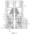
- FIG. 4depicts an expanded lower portion of the MR damper of FIG. 3 ;
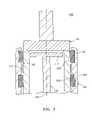
- FIG. 5depicts an expanded upper portion of the MR damper of FIG. 3 ;
- FIG. 6depicts a suspension damping system in accordance with embodiments of the invention.
- FIG. 7depicts an alternative embodiment to that depicted in FIG. 4 .
- An embodiment of the inventionutilizes controllable magnetorheological (MR) dampers in struts in the suspension system of a vehicle, thereby providing continuously controllable damping characteristics to the vehicle.
- Embodiments of the inventionmay use MR dampers in the front struts only, as replacements for the rear shock absorbers only, or for both purposes.
- an electronic control module(controller) is used with suspension relative displacement sensors (one per wheel corner), and may also be used with a vehicle lateral accelerometer, a steering angle sensor and a vehicle speed sensor, for providing an excitation signal to the MR damper to allow for continuous modification of the damping characteristics of the vehicle suspension system.
- control modulemay send a range of activation signals to the MR dampers resulting in a range of vehicle suspension damping characteristics.
- a driver-actuated switchmay work in conjunction with the controller for providing a high or low gain factor to the excitation signal depending on whether the driver prefers a stiffer ride or a smoother ride.
- FIG. 1is an exemplary embodiment of a vehicle 100 having a body 102 , a set of wheels 103 , a front suspension system 105 with a front strut 110 , and a rear suspension system 115 having a rear spring 120 and rear shock absorber 125 .
- Front strut 110includes a front spring 130 and a front shock absorber 135 .
- shock absorbers 125 and 135may separately be or may both be magnetorheological fluid (MR) dampers, such as that depicted in FIG. 3 . While FIG. 3 depicts shock absorber 135 as a MR damper, it will be appreciated that the same figure may also relate to shock absorber 125 . Accordingly, and as used herein, numeral 135 refers to a MR damper that may be utilized as a front shock absorber 135 or a rear shock absorber 125 .
- MRmagnetorheological fluid
- Embodiments of the inventionmay use any one of several different types of MR dampers 135 depending on the packaging space.
- An exemplary MR damper 135is a damper that utilizes a minimum amount of MR fluid and achieves the desired damping characteristics in response to a variable excitation signal.
- the amount of MR fluid usedis equal to or less than about 50 cc (cubic centimeters), and preferably equal to or less than about 10 cc, compared with more than 100 cc used in other MR damper type devices.
- linearly translating MR dampersthat use greater than about 50 cc of MR fluid.
- FIGS. 3-5depict a cross-section block representation of a complete MR damper 135 ( FIG. 3 ), an expanded lower portion 140 of MR damper 135 ( FIG. 4 ), and an expanded upper portion 145 of MR damper 135 ( FIG. 5 ).
- MR damper 135utilizes a magnetorheological fluid 150 dispensed in an annular space 155 between two concentric cylinders 160 , 165 made of magnetic material where it is subjected to a controllable magnetic field 170 .
- Cylinder 160is also herein referred to as a stator 160
- cylinder 165is also herein referred to as a core 165 .
- annular space 155Within annular space 155 is disposed a magnetic cylindrical rotor 175 , which is surrounded by the MR fluid 150 .
- the MR fluid 150may be easily sheared to produce little resistance to rotation of rotor 175 , whereas under a continuously variable magnetic field 170 , the MR fluid 150 exhibits a yield stress that increases as a function of magnetic field strength, thereby resisting rotation and generating a significant variable opposing torque on rotor 175 within MR fluid 150 of MR damper 135 .
- annular space 155is sized to hold equal to or less than about 50 cc of MR fluid 150 , and in another embodiment is sized to hold equal to or less than about 10 cc of MR fluid 150 .
- MR damper 135includes first 180 , second 185 and third 190 portions.
- First and second portions 180 , 185are disposed having a translational degree of freedom parallel to axis 195 and with respect to each other, and third portion 190 is disposed having a rotational degree of freedom about axis 195 and with respect to the first and second portions 180 , 185 .
- First and third portions 180 , 190are coupled via a translation-to-rotation converter 200
- second and third portions 185 , 190are coupled via MR fluid 150 within annular space 155 .
- a magnetic field generator 205 at lower portion 140is in field communication with the MR fluid 150 within the annular space 155 , and includes a core 210 and a coil 215 .
- a signal path provided by leads 220 and connector 225enables excitation signals to be received at coil 215 for producing magnetic field 170 .
- Third portion 190is rotationally responsive to translational motion between the first and second portions 180 , 185 , and the shear stress characteristic of the MR fluid 150 within annular space 155 is responsive to magnetic field generator 205 , such that a rotational damping action of third portion 190 results from field excitation at magnetic field generator 205 .
- first portion 180includes a cylindrical tube 230 having a ball nut 235
- third portion 190includes a shaft 240 having a ball screw 245 at one end and the magnetic rotor 175 at an opposing end
- second portion 185includes a cylindrical, metallic (such as magnetic steel, non-magnetic steel, aluminum, or magnesium, for example) housing 250 receptive of the first portion 180 , the third portion 190 , and the magnetic field generator 205 .
- Ball screw 245is engagingly disposed at ball nut 235 for providing rotational motion therebetween
- magnetic rotor 175is disposed within the MR fluid 150 at annular space 155 that provides fluid communication therebetween.
- first 180 and second 185 portionsDisposed between first 180 and second 185 portions, where in an embodiment each have cylindrical cross sections, are ring bearings 255 , 260 for supporting a side load between first and second portions 180 , 185 .
- Ring bearings 255 , 260are axially displaced with respect to each other to define an interspatial region 265 that may contain a lubricant 270 for reducing sliding friction between first and second portions 180 , 185 .
- the cylindrical wall of second portion 185has an interior surface that includes circumferential recesses, or channels, 275 and 280 for securely receiving and fixing ring bearings 255 , 260 .
- Ring bearings 255 , 260may be ball bearings in a bearing race, lubricious bearing material such as bronze for example, or any other bearing device or material suitable for the purposes disclosed herein.
- the bearings 255 , 260may also be secured in place by crimping the portions of the tube 250 immediately adjacent to both sides of each bearing, as depicted generally by crimp 252 in FIG. 5 . While only one crimp 252 is depicted in FIG. 5 , it will be appreciated that crimp 252 may be applied to tube 250 at both sides of each bearing 255 , 260 , thereby securing bearings 255 , 260 in place.
- first, second and third portions 180 , 185 , 190form a linear-to-rotary conversion device made up of ball screw 245 and ball nut 235 , where ball nut 235 is attached to the lower end of cylindrical tube 230 , and ball screw 245 is attached to the cylindrical magnetic rotor 175 through a non-magnetic support disc 285 .
- the upper end of second portion 185is attached to a spring cup 290 for retaining the lower end of front suspension spring 130 , best seen by referring to FIG. 2 , the lower end of second portion 185 is attached to wheel support 295 via bracket 300 , best seen by referring to FIGS.
- Ball screw 245is secured to rotate within a metallic housing 250 and non-magnetic housing end cover 305 by means of a sealed bushing 310 and a sealed thrust ball bearing 315 at one end, and by means of a ball screw end support 317 at the other end.
- Ball screw end support 317serves to maintain the axial relationship of ball screw 245 with respect to the tube 230 of first portion 180 .
- a jounce bumper 350made of an elastomeric material is disposed between first and second portions 180 , 185 for absorbing impact forces acting therebetween.
- Magnetic rotor 175is disposed between the soft magnetic cylindrical stator 160 and the soft magnetic cylindrical core 165 , which are captivated within cylindrical housing 250 .
- Core 165 and encapsulated magnetic coil 215together make up the magnetic field generator 205 .
- the annular space 155 formed between the cylindrical surface of stator 160 and the cylindrical surface of core 165is filled with the MR fluid 150 that is prevented from leaking out of MR damper 135 by dynamic O-ring seals 320 , 321 , which dynamically interface with the rotational motion of third portion 190 .
- dynamic O-ring seals 320 , 321are used, while in an alternative embodiment depicted in FIG. 7 , only a single dynamic O-ring seal 322 is used, which aids to further reduce friction and component wear.
- static O-rings 323may be used provide additional sealing for MR fluid 150 .
- cylindrical rotor 175has three cylindrical sections 325 , 330 and 335 , with first and second sections 325 , 330 being made of magnetic material, as discussed previously, and third section 335 being made of substantially non-magnetic material.
- Third section 335is radially disposed with respect to coil 215 , thereby providing the desired flux path for magnetic field 170 through the aforementioned magnetic material.
- Third section 335may be made up of substantially non-magnetic material such as stainless steel, aluminum, brass, for example, or may have a rib 340 of magnetic material having such a thickness that it prevents a significant amount of magnetic flux from being diverted away from the portion of annular space 155 closest to stator 160 .
- a magnetic field 170is produced in the radial direction with respect to axis 195 across annular space 155 between core 165 , rotor 175 and stator 160 .
- the strength of the magnetic field or flux density within MR fluid 150determines the shear stress characteristics of MR fluid 150 , thereby controlling the degree of torque that acts to resist the rotation of magnetic rotor 175 .
- the resulting magnetic flux lines 170 that traverse annular space 155are depicted in FIGS. 3 and 4 .
- the resisting torque acting on magnetic rotor 175translates to a force that resists the linear movement of ball nut 235 and attached cylindrical tube 230 .
- the pitch of ball screw 245By the appropriate selection of: the pitch of ball screw 245 ; the axial and radial dimensions of stator 160 , core 165 , and rotor 175 ; the number of turns of coil 215 ; the range of currents through coil 215 ; and an MR fluid 150 with a suitable concentration of iron particles, forces sufficient to dampen the translational movement between first and second portions 180 , 185 , and thus axial movement of strut 110 , may be generated by controlled activation of MR damper 135 .
- the above noted parametersmay be chosen in such a way as to achieve minimum force generation when the current through coil 215 is set to zero, thereby resulting in a de-coupled operation of strut 110 .
- suspension damping system 400includes a plurality of sensors 405 , 410 , 415 , 435 , a controller 420 , and at least one MR damper 135 .
- Sensors 405 , 410 , 415 , 435 and controller 420may also be herein referred to as an electronic control system 425 .
- the plurality of sensorsincludes a vehicle speed sensor 405 , a steering angle sensor 410 , four suspension relative-displacement sensors 435 (one per wheel corner for example), and/or a lateral accelerometer 415 , which are responsive to the respective operating characteristic of vehicle 100 .
- Controller 420is responsive to signals from the plurality of sensors 405 , 410 , 415 , 435 for generating an activation signal that causes an increase in the shear strength of the MR fluid 150 , an opposing torque action at rotor 175 , and an opposing translation-to-rotation conversion action at converter 200 , thereby changing the damping characteristics of strut 110 on demand. While FIG. 6 depicts two front shock absorbers 135 , but only one rear shock absorber 125 , it will be appreciated that this is for illustration purposes only, and that vehicle 100 may include a second rear shock absorber, not shown, that also functions in accordance with embodiments of the invention.
- sensors 405 , 410 , 415 , 435provide controller 420 with input signals that enable controller 420 to provide a continuous stream of control signals to MR damper 135 , thereby enabling MR damper 135 to be continually responsive to dynamic driving conditions.
- vehicle 100is equipped with a driver-actuated switch 430 that works in conjunction with controller 420 for providing a high or low gain factor to the excitation signal sent to coil 215 depending on whether the driver prefers a stiffer ride or a smoother ride. Whether switch 430 is in a stiff ride position or a smooth ride position, controller 420 is capable of providing a continuous stream of signals to MR damper 135 for continually adjusting the damping characteristics of strut 110 .
- embodiments of the inventionmay perform a method of controlling a vehicle suspension damping system 400 by, receiving at controller 420 signals from sensors 405 , 410 , 415 , 435 , analyzing the signals and generating an activation signal in response thereto, and activating MR damper 135 in response to the activation signal so as to cause an increase in the shear strength of MR fluid 175 , an opposing torque action at magnetic rotor 175 , an opposing translation-to-rotation conversion action at converter 200 , and increased damping of translational motion between first and second portions 180 , 185 of strut 110 absent the complete restraint of first portion 180 with respect to second portion 185 .
- some embodiments of the inventionmay include some of the following advantages: a low cost automotive suspension damping system with side load withstand capability absent the requirement of a hydraulic pump or hydraulic power; lower system cost as a result of small MR fluid usage; lower system cost due to the elimination of gas springs, high-pressure seals and special rod and tube finishes required to minimize abrasion in a telescopic MR damper-type shock absorber device; lower cost by eliminating the need to have a gas reservoir to accommodate fluid displacement by rod volume; improved ride comfort and quality; reduced head toss during a vehicle maneuver; utilization of an MR damper that has a fast response time on the order of 10 milliseconds; reduced package size due to the elimination of accumulator and hydraulic lines; the ability to be utilized for controlling vehicle stability in vehicle oversteering conditions; improved vehicle ride quality during straight driving; and, minimal parasitic power consumption due to the absence of high electrical or hydraulic power demand under normal driving operation.
Landscapes
- Engineering & Computer Science (AREA)
- Mechanical Engineering (AREA)
- General Engineering & Computer Science (AREA)
- Physics & Mathematics (AREA)
- Electromagnetism (AREA)
- Vehicle Body Suspensions (AREA)
- Fluid-Damping Devices (AREA)
Abstract
Description
Claims (16)
Priority Applications (3)
| Application Number | Priority Date | Filing Date | Title |
|---|---|---|---|
| US11/008,419US7303056B2 (en) | 2004-12-09 | 2004-12-09 | Magnetorheological device and system and method for using the same |
| DE102005058254.0ADE102005058254B4 (en) | 2004-12-09 | 2005-12-06 | Magnetorheological device and magnetorheological system and method of using the same |
| US11/974,133US7686143B2 (en) | 2004-12-09 | 2007-10-11 | Magnetorheological device and system and method for using the same |
Applications Claiming Priority (1)
| Application Number | Priority Date | Filing Date | Title |
|---|---|---|---|
| US11/008,419US7303056B2 (en) | 2004-12-09 | 2004-12-09 | Magnetorheological device and system and method for using the same |
Related Child Applications (1)
| Application Number | Title | Priority Date | Filing Date |
|---|---|---|---|
| US11/974,133DivisionUS7686143B2 (en) | 2004-12-09 | 2007-10-11 | Magnetorheological device and system and method for using the same |
Publications (2)
| Publication Number | Publication Date |
|---|---|
| US20060124413A1 US20060124413A1 (en) | 2006-06-15 |
| US7303056B2true US7303056B2 (en) | 2007-12-04 |
Family
ID=36500373
Family Applications (2)
| Application Number | Title | Priority Date | Filing Date |
|---|---|---|---|
| US11/008,419Expired - Fee RelatedUS7303056B2 (en) | 2004-12-09 | 2004-12-09 | Magnetorheological device and system and method for using the same |
| US11/974,133Expired - Fee RelatedUS7686143B2 (en) | 2004-12-09 | 2007-10-11 | Magnetorheological device and system and method for using the same |
Family Applications After (1)
| Application Number | Title | Priority Date | Filing Date |
|---|---|---|---|
| US11/974,133Expired - Fee RelatedUS7686143B2 (en) | 2004-12-09 | 2007-10-11 | Magnetorheological device and system and method for using the same |
Country Status (2)
| Country | Link |
|---|---|
| US (2) | US7303056B2 (en) |
| DE (1) | DE102005058254B4 (en) |
Cited By (7)
| Publication number | Priority date | Publication date | Assignee | Title |
|---|---|---|---|---|
| US20090234536A1 (en)* | 2008-03-12 | 2009-09-17 | Gm Global Technology Operations, Inc. | High bandwidth control of magnetic ride control system |
| US20110121223A1 (en)* | 2009-11-23 | 2011-05-26 | Gm Global Technology Operations, Inc. | Magnetorheological fluids and methods of making and using the same |
| US20120119123A1 (en)* | 2009-07-21 | 2012-05-17 | Inventus Engineering Gmbh | Adjustable valve with a transition region |
| US20150136548A1 (en)* | 2012-05-22 | 2015-05-21 | Kabushiki Kaisha Somic Ishikawa | Braking device |
| EP3078877A1 (en)* | 2015-04-10 | 2016-10-12 | Messier-Dowty Ltd | Hydraulic shock absorber |
| US10166832B2 (en)* | 2014-08-04 | 2019-01-01 | Firestone Industrial Products Company, Llc | Performance-variable bushings as well as gas spring and damper assemblies including same |
| US20190248203A1 (en)* | 2016-10-27 | 2019-08-15 | Schaeffler Technologies AG & Co. KG | Electromechanical chasis actuator |
Families Citing this family (52)
| Publication number | Priority date | Publication date | Assignee | Title |
|---|---|---|---|---|
| DE102008024166B4 (en)* | 2007-05-19 | 2014-11-27 | Stabilus Gmbh | Piston-cylinder assembly |
| US8424656B2 (en)* | 2007-06-15 | 2013-04-23 | Techno-Sciences, Inc. | Rotary vane magnetorheological (MR) energy absorber |
| GB0805829D0 (en)* | 2008-04-01 | 2008-04-30 | Goodrich Actuation Systems Ltd | Damping arrangement |
| US11306798B2 (en) | 2008-05-09 | 2022-04-19 | Fox Factory, Inc. | Position sensitive suspension damping with an active valve |
| US9033122B2 (en) | 2009-01-07 | 2015-05-19 | Fox Factory, Inc. | Method and apparatus for an adjustable damper |
| US20120305350A1 (en) | 2011-05-31 | 2012-12-06 | Ericksen Everet O | Methods and apparatus for position sensitive suspension damping |
| US10060499B2 (en) | 2009-01-07 | 2018-08-28 | Fox Factory, Inc. | Method and apparatus for an adjustable damper |
| US8627932B2 (en) | 2009-01-07 | 2014-01-14 | Fox Factory, Inc. | Bypass for a suspension damper |
| US9452654B2 (en) | 2009-01-07 | 2016-09-27 | Fox Factory, Inc. | Method and apparatus for an adjustable damper |
| US8857580B2 (en) | 2009-01-07 | 2014-10-14 | Fox Factory, Inc. | Remotely operated bypass for a suspension damper |
| US10047817B2 (en) | 2009-01-07 | 2018-08-14 | Fox Factory, Inc. | Method and apparatus for an adjustable damper |
| US20100170760A1 (en) | 2009-01-07 | 2010-07-08 | John Marking | Remotely Operated Bypass for a Suspension Damper |
| CN102112776B (en)* | 2008-06-02 | 2014-10-29 | 洛德公司 | Magnetorheological fluid damper with increased opening yield strength |
| US8393446B2 (en) | 2008-08-25 | 2013-03-12 | David M Haugen | Methods and apparatus for suspension lock out and signal generation |
| US9422018B2 (en) | 2008-11-25 | 2016-08-23 | Fox Factory, Inc. | Seat post |
| US10036443B2 (en) | 2009-03-19 | 2018-07-31 | Fox Factory, Inc. | Methods and apparatus for suspension adjustment |
| US9140325B2 (en) | 2009-03-19 | 2015-09-22 | Fox Factory, Inc. | Methods and apparatus for selective spring pre-load adjustment |
| US11299233B2 (en) | 2009-01-07 | 2022-04-12 | Fox Factory, Inc. | Method and apparatus for an adjustable damper |
| US10821795B2 (en) | 2009-01-07 | 2020-11-03 | Fox Factory, Inc. | Method and apparatus for an adjustable damper |
| US9038791B2 (en) | 2009-01-07 | 2015-05-26 | Fox Factory, Inc. | Compression isolator for a suspension damper |
| US12122205B2 (en) | 2009-01-07 | 2024-10-22 | Fox Factory, Inc. | Active valve for an internal bypass |
| US8936139B2 (en) | 2009-03-19 | 2015-01-20 | Fox Factory, Inc. | Methods and apparatus for suspension adjustment |
| GB2469804B (en)* | 2009-04-27 | 2013-08-21 | Messier Dowty Ltd | Bearing assembly |
| EP2312180B1 (en)* | 2009-10-13 | 2019-09-18 | Fox Factory, Inc. | Apparatus for controlling a fluid damper |
| US8672106B2 (en) | 2009-10-13 | 2014-03-18 | Fox Factory, Inc. | Self-regulating suspension |
| JP2011121534A (en)* | 2009-12-14 | 2011-06-23 | Honda Motor Co Ltd | Active noise control device |
| US10697514B2 (en) | 2010-01-20 | 2020-06-30 | Fox Factory, Inc. | Remotely operated bypass for a suspension damper |
| EP2402239B1 (en) | 2010-07-02 | 2020-09-02 | Fox Factory, Inc. | Adjustable seat post |
| DE102011105547B4 (en) | 2011-06-24 | 2023-05-11 | Volkswagen Aktiengesellschaft | Torsion bar suspension device for a vehicle and method for controlling the dynamic properties of a vehicle |
| KR101298267B1 (en)* | 2011-08-01 | 2013-08-22 | 현대자동차주식회사 | Orifice-plate for an engine-mount filled with the Magnetorheological fluid |
| EP3929459A1 (en) | 2011-09-12 | 2021-12-29 | Fox Factory, Inc. | Methods and apparatus for suspension set up |
| CN103874867B (en)* | 2011-10-19 | 2016-08-31 | Thk株式会社 | Attenuating device |
| US11279199B2 (en) | 2012-01-25 | 2022-03-22 | Fox Factory, Inc. | Suspension damper with by-pass valves |
| US10330171B2 (en) | 2012-05-10 | 2019-06-25 | Fox Factory, Inc. | Method and apparatus for an adjustable damper |
| US9109654B2 (en)* | 2012-06-12 | 2015-08-18 | Inno Vital Systems, Inc. | Failsafe magnetorheological (MR) energy absorber |
| DE102012215614A1 (en)* | 2012-09-04 | 2014-05-28 | Zf Friedrichshafen Ag | Vibration damper for use as e.g. two-pipe vibration damper, has absorbing device attached to rotationable mass, and piston rod connected with thread portion of spindle drive on which rotationable mass is axially supported on cylinder |
| US9085317B2 (en) | 2013-07-17 | 2015-07-21 | GM Global Technology Operations LLC | Systems and methods for variable steering assist |
| DE102015104927A1 (en)* | 2015-03-31 | 2016-10-06 | Inventus Engineering Gmbh | Damper for damping a relative movement |
| ES2703452T3 (en)* | 2015-09-23 | 2019-03-08 | Mag Soar Sl | Enhanced magnetic vibration damper with mechanical impedance matching |
| KR102251270B1 (en)* | 2016-01-05 | 2021-05-11 | 밀워키 일렉트릭 툴 코포레이션 | Vibration reduction system and method for power tools |
| CN105545954A (en)* | 2016-02-17 | 2016-05-04 | 张广 | Tapered roller bearing combining displacement compensation function and vibration reduction function |
| US10052928B2 (en)* | 2016-04-07 | 2018-08-21 | GM Global Technology Operations LLC | Ride height control actuator |
| US10737546B2 (en) | 2016-04-08 | 2020-08-11 | Fox Factory, Inc. | Electronic compression and rebound control |
| US10696336B2 (en)* | 2017-10-17 | 2020-06-30 | GM Global Technology Operations LLC | Actuation system having a magnetorheological damper |
| CN108980258B (en)* | 2018-07-09 | 2020-07-31 | 江苏大学 | A magnetorheological damping regulating valve |
| IT201900005722A1 (en) | 2019-04-12 | 2020-10-12 | Automobili Lamborghini Spa | SYSTEM AND METHOD FOR CHECKING THE STABILITY OF A VEHICLE EQUIPPED WITH SEMI-ACTIVE SUSPENSIONS |
| CN110219927B (en)* | 2019-07-15 | 2024-04-12 | 连云港师范高等专科学校 | Shock absorber bottom non-axial component force anti-drag device based on magnetorheological fluid |
| CN111152616B (en)* | 2020-01-08 | 2022-09-27 | 合肥工业大学 | A magnetorheological damping suspension and its measurement and control method |
| CN114368428B (en)* | 2022-01-11 | 2023-07-28 | 湖北汽车工业学院 | An electronic chip circuit board control device with a wire-controlled chassis |
| CN114810919B (en)* | 2022-03-18 | 2024-07-02 | 合肥工业大学 | A vibration reduction system with active damping control and control method thereof |
| CN114993852B (en)* | 2022-05-17 | 2024-08-09 | 重庆大学 | Magnetic sensitive intelligent material multi-physical quantity testing device under high shear rate |
| US20250276551A1 (en)* | 2024-03-01 | 2025-09-04 | Ford Global Technologies, Llc | Shock mounted linear suspension height sensor with accelerometer |
Citations (15)
| Publication number | Priority date | Publication date | Assignee | Title |
|---|---|---|---|---|
| JPS639739A (en)* | 1986-06-30 | 1988-01-16 | Sanwa Tekki Corp | Viscous damper |
| US4815575A (en) | 1988-04-04 | 1989-03-28 | General Motors Corporation | Electric, variable damping vehicle suspension |
| JPH01216138A (en)* | 1988-02-24 | 1989-08-30 | Sanwa Tekki Corp | Magnetic adjusting type vibration suppressing device |
| US5630623A (en) | 1994-08-15 | 1997-05-20 | Kelsey Hayes | Vehicle roll control system |
| JPH09264492A (en)* | 1996-03-28 | 1997-10-07 | Sanwa Tekki Corp | Vibration control device for electrical viscous fluid |
| US5878997A (en)* | 1997-09-10 | 1999-03-09 | Lucent Technologies Inc. | Compact low-inductance magnetorheological damper |
| US6279701B1 (en) | 1999-09-13 | 2001-08-28 | Delphi Technologies, Inc. | Magnetorheological fluid damper with multiple annular flow gaps |
| US6390252B1 (en) | 1999-09-13 | 2002-05-21 | Delphi Technologies, Inc. | Magnetorheological fluid damper with optimum damping |
| US6471018B1 (en)* | 1998-11-20 | 2002-10-29 | Board Of Regents Of The University And Community College System On Behalf Of The University Of Nevada-Reno, The University Of Reno | Magneto-rheological fluid device |
| KR20030004147A (en)* | 2002-09-05 | 2003-01-14 | 강성덕 | ball screw magnetorheological damper |
| US20030062214A1 (en)* | 2001-10-01 | 2003-04-03 | Delphi Technologies, Inc. | Flexible no-lash drive plate |
| US6641166B2 (en)* | 2001-05-25 | 2003-11-04 | General Motors Corporation | Extendable and retractable knee bolster system |
| US6662912B2 (en)* | 2000-11-03 | 2003-12-16 | Delphi Technologies, Inc. | Magneto-rheological steering damper |
| US6883649B2 (en)* | 2003-03-21 | 2005-04-26 | Delphi Technologies, Inc. | Closing system for a magneto-rheological damper |
| US20050121269A1 (en)* | 2003-12-08 | 2005-06-09 | Namuduri Chandra S. | Fluid damper having continuously variable damping response |
Family Cites Families (12)
| Publication number | Priority date | Publication date | Assignee | Title |
|---|---|---|---|---|
| US4630623A (en)* | 1983-03-16 | 1986-12-23 | Joseph Hadary | Toothpick holder |
| JPS611522A (en)* | 1984-06-14 | 1986-01-07 | Nissan Motor Co Ltd | Suspension controller in vehicles |
| KR930009381B1 (en)* | 1989-05-29 | 1993-10-02 | 미쓰비시덴키 가부시키가이샤 | Controller for suspension stabilizer |
| CA2138549C (en)* | 1992-06-18 | 2001-12-18 | J. David Carlson | Magnetorheological fluid devices |
| US5992582A (en)* | 1994-04-19 | 1999-11-30 | Lou; Zheng | Electrorheological rotary pure-shear damping devices |
| US6186290B1 (en)* | 1997-10-29 | 2001-02-13 | Lord Corporation | Magnetorheological brake with integrated flywheel |
| DE19940420B4 (en)* | 1998-08-26 | 2013-07-11 | Honda Giken Kogyo K.K. | Stabilizer effectiveness controller |
| KR100696934B1 (en)* | 2000-03-28 | 2007-03-21 | 주식회사 만도 | Shock absorber using magnetorheological fluid |
| GB2372794B (en)* | 2001-02-02 | 2004-07-07 | Trysome Ltd | A magnetorheological fluid damper |
| EP1510721B1 (en)* | 2002-06-06 | 2010-06-30 | Kayaba Industry Co., Ltd. | Electromagnetic shock absorber |
| US7275750B2 (en)* | 2004-05-12 | 2007-10-02 | General Motors Corporation | Roll control system, device and method for controlling vehicle stability |
| DE102004058738A1 (en) | 2004-12-06 | 2006-06-08 | Truma Gerätetechnik GmbH & Co. KG | Auxiliary drive for a trailer |
- 2004
- 2004-12-09USUS11/008,419patent/US7303056B2/ennot_activeExpired - Fee Related
- 2005
- 2005-12-06DEDE102005058254.0Apatent/DE102005058254B4/ennot_activeExpired - Fee Related
- 2007
- 2007-10-11USUS11/974,133patent/US7686143B2/ennot_activeExpired - Fee Related
Patent Citations (15)
| Publication number | Priority date | Publication date | Assignee | Title |
|---|---|---|---|---|
| JPS639739A (en)* | 1986-06-30 | 1988-01-16 | Sanwa Tekki Corp | Viscous damper |
| JPH01216138A (en)* | 1988-02-24 | 1989-08-30 | Sanwa Tekki Corp | Magnetic adjusting type vibration suppressing device |
| US4815575A (en) | 1988-04-04 | 1989-03-28 | General Motors Corporation | Electric, variable damping vehicle suspension |
| US5630623A (en) | 1994-08-15 | 1997-05-20 | Kelsey Hayes | Vehicle roll control system |
| JPH09264492A (en)* | 1996-03-28 | 1997-10-07 | Sanwa Tekki Corp | Vibration control device for electrical viscous fluid |
| US5878997A (en)* | 1997-09-10 | 1999-03-09 | Lucent Technologies Inc. | Compact low-inductance magnetorheological damper |
| US6471018B1 (en)* | 1998-11-20 | 2002-10-29 | Board Of Regents Of The University And Community College System On Behalf Of The University Of Nevada-Reno, The University Of Reno | Magneto-rheological fluid device |
| US6279701B1 (en) | 1999-09-13 | 2001-08-28 | Delphi Technologies, Inc. | Magnetorheological fluid damper with multiple annular flow gaps |
| US6390252B1 (en) | 1999-09-13 | 2002-05-21 | Delphi Technologies, Inc. | Magnetorheological fluid damper with optimum damping |
| US6662912B2 (en)* | 2000-11-03 | 2003-12-16 | Delphi Technologies, Inc. | Magneto-rheological steering damper |
| US6641166B2 (en)* | 2001-05-25 | 2003-11-04 | General Motors Corporation | Extendable and retractable knee bolster system |
| US20030062214A1 (en)* | 2001-10-01 | 2003-04-03 | Delphi Technologies, Inc. | Flexible no-lash drive plate |
| KR20030004147A (en)* | 2002-09-05 | 2003-01-14 | 강성덕 | ball screw magnetorheological damper |
| US6883649B2 (en)* | 2003-03-21 | 2005-04-26 | Delphi Technologies, Inc. | Closing system for a magneto-rheological damper |
| US20050121269A1 (en)* | 2003-12-08 | 2005-06-09 | Namuduri Chandra S. | Fluid damper having continuously variable damping response |
Cited By (12)
| Publication number | Priority date | Publication date | Assignee | Title |
|---|---|---|---|---|
| US20090234536A1 (en)* | 2008-03-12 | 2009-09-17 | Gm Global Technology Operations, Inc. | High bandwidth control of magnetic ride control system |
| US8055408B2 (en)* | 2008-03-12 | 2011-11-08 | GM Global Technology Operations LLC | High bandwidth control of magnetic ride control system |
| US20120119123A1 (en)* | 2009-07-21 | 2012-05-17 | Inventus Engineering Gmbh | Adjustable valve with a transition region |
| US8985149B2 (en)* | 2009-07-21 | 2015-03-24 | Inventus Engineering Gmbh | Adjustable valve with a transition region |
| US20110121223A1 (en)* | 2009-11-23 | 2011-05-26 | Gm Global Technology Operations, Inc. | Magnetorheological fluids and methods of making and using the same |
| US20150136548A1 (en)* | 2012-05-22 | 2015-05-21 | Kabushiki Kaisha Somic Ishikawa | Braking device |
| US9410588B2 (en)* | 2012-05-22 | 2016-08-09 | Kabushiki Kaisha Sonic Ishikawa | Braking device |
| US10166832B2 (en)* | 2014-08-04 | 2019-01-01 | Firestone Industrial Products Company, Llc | Performance-variable bushings as well as gas spring and damper assemblies including same |
| EP3078877A1 (en)* | 2015-04-10 | 2016-10-12 | Messier-Dowty Ltd | Hydraulic shock absorber |
| US10024379B2 (en) | 2015-04-10 | 2018-07-17 | Safran Landing Systems Uk Ltd | Hydraulic shock absorber |
| US20190248203A1 (en)* | 2016-10-27 | 2019-08-15 | Schaeffler Technologies AG & Co. KG | Electromechanical chasis actuator |
| US11001116B2 (en)* | 2016-10-27 | 2021-05-11 | Schaeffler Technologies Ag & Co Kg | Electromechanical chasis actuator |
Also Published As
| Publication number | Publication date |
|---|---|
| US7686143B2 (en) | 2010-03-30 |
| US20060124413A1 (en) | 2006-06-15 |
| US20080041677A1 (en) | 2008-02-21 |
| DE102005058254A1 (en) | 2006-06-14 |
| DE102005058254B4 (en) | 2014-02-13 |
Similar Documents
| Publication | Publication Date | Title |
|---|---|---|
| US7303056B2 (en) | Magnetorheological device and system and method for using the same | |
| US7232016B2 (en) | Fluid damper having continuously variable damping response | |
| US7275750B2 (en) | Roll control system, device and method for controlling vehicle stability | |
| US6547044B2 (en) | Magneto-rheological damper with ferromagnetic housing insert | |
| EP2012042B1 (en) | Damper | |
| EP1932693B1 (en) | Electromagnetic shock absorber for vehicle | |
| JP5260936B2 (en) | Electromagnetic shock absorber for vehicles | |
| US5632361A (en) | Vibration damper, in particular for motor vehicles | |
| US6032770A (en) | Low force actuator for suspension control | |
| US7950506B2 (en) | Semi third tube design | |
| US9109654B2 (en) | Failsafe magnetorheological (MR) energy absorber | |
| US7510060B2 (en) | Damper with variable damping force | |
| CN101351657B (en) | Shock absorber | |
| EP2012043A1 (en) | Damper | |
| US11280379B2 (en) | Chassis component with a rotary damper | |
| WO2004061328A1 (en) | Magnetorheological twin-tube damping device | |
| WO2019164771A1 (en) | Active damper system actuator arrangement | |
| JP2002349630A (en) | Friction control hydraulic shock absorber and suspension control device | |
| CN119289026A (en) | Suspension actuator integrating electromagnetic, oil-gas and inertia characteristics and control method thereof | |
| JP2008100539A (en) | Vehicle suspension system | |
| JPS62251220A (en) | buffer | |
| JP4329670B2 (en) | Vehicle suspension system | |
| JP2008247054A (en) | Vehicle suspension system | |
| JP4094088B2 (en) | Hydraulic shock absorber for vehicles | |
| KR20190088260A (en) | Shock Absorber |
Legal Events
| Date | Code | Title | Description |
|---|---|---|---|
| AS | Assignment | Owner name:GENERAL MOTORS CORPORATION, MICHIGAN Free format text:ASSIGNMENT OF ASSIGNORS INTEREST;ASSIGNOR:NAMUDURI, CHANDRA S.;REEL/FRAME:015694/0832 Effective date:20041117 | |
| STCF | Information on status: patent grant | Free format text:PATENTED CASE | |
| AS | Assignment | Owner name:GM GLOBAL TECHNOLOGY OPERATIONS, INC., MICHIGAN Free format text:ASSIGNMENT OF ASSIGNORS INTEREST;ASSIGNOR:GENERAL MOTORS CORPORATION;REEL/FRAME:022102/0533 Effective date:20050119 Owner name:GM GLOBAL TECHNOLOGY OPERATIONS, INC.,MICHIGAN Free format text:ASSIGNMENT OF ASSIGNORS INTEREST;ASSIGNOR:GENERAL MOTORS CORPORATION;REEL/FRAME:022102/0533 Effective date:20050119 | |
| AS | Assignment | Owner name:UNITED STATES DEPARTMENT OF THE TREASURY, DISTRICT Free format text:SECURITY AGREEMENT;ASSIGNOR:GM GLOBAL TECHNOLOGY OPERATIONS, INC.;REEL/FRAME:022201/0610 Effective date:20081231 Owner name:UNITED STATES DEPARTMENT OF THE TREASURY,DISTRICT Free format text:SECURITY AGREEMENT;ASSIGNOR:GM GLOBAL TECHNOLOGY OPERATIONS, INC.;REEL/FRAME:022201/0610 Effective date:20081231 | |
| AS | Assignment | Owner name:CITICORP USA, INC. AS AGENT FOR BANK PRIORITY SECU Free format text:SECURITY AGREEMENT;ASSIGNOR:GM GLOBAL TECHNOLOGY OPERATIONS, INC.;REEL/FRAME:022553/0446 Effective date:20090409 Owner name:CITICORP USA, INC. AS AGENT FOR HEDGE PRIORITY SEC Free format text:SECURITY AGREEMENT;ASSIGNOR:GM GLOBAL TECHNOLOGY OPERATIONS, INC.;REEL/FRAME:022553/0446 Effective date:20090409 | |
| AS | Assignment | Owner name:GM GLOBAL TECHNOLOGY OPERATIONS, INC., MICHIGAN Free format text:RELEASE BY SECURED PARTY;ASSIGNOR:UNITED STATES DEPARTMENT OF THE TREASURY;REEL/FRAME:023124/0429 Effective date:20090709 Owner name:GM GLOBAL TECHNOLOGY OPERATIONS, INC.,MICHIGAN Free format text:RELEASE BY SECURED PARTY;ASSIGNOR:UNITED STATES DEPARTMENT OF THE TREASURY;REEL/FRAME:023124/0429 Effective date:20090709 | |
| AS | Assignment | Owner name:GM GLOBAL TECHNOLOGY OPERATIONS, INC., MICHIGAN Free format text:RELEASE BY SECURED PARTY;ASSIGNORS:CITICORP USA, INC. AS AGENT FOR BANK PRIORITY SECURED PARTIES;CITICORP USA, INC. AS AGENT FOR HEDGE PRIORITY SECURED PARTIES;REEL/FRAME:023127/0468 Effective date:20090814 Owner name:GM GLOBAL TECHNOLOGY OPERATIONS, INC.,MICHIGAN Free format text:RELEASE BY SECURED PARTY;ASSIGNORS:CITICORP USA, INC. AS AGENT FOR BANK PRIORITY SECURED PARTIES;CITICORP USA, INC. AS AGENT FOR HEDGE PRIORITY SECURED PARTIES;REEL/FRAME:023127/0468 Effective date:20090814 | |
| AS | Assignment | Owner name:UNITED STATES DEPARTMENT OF THE TREASURY, DISTRICT Free format text:SECURITY AGREEMENT;ASSIGNOR:GM GLOBAL TECHNOLOGY OPERATIONS, INC.;REEL/FRAME:023156/0052 Effective date:20090710 Owner name:UNITED STATES DEPARTMENT OF THE TREASURY,DISTRICT Free format text:SECURITY AGREEMENT;ASSIGNOR:GM GLOBAL TECHNOLOGY OPERATIONS, INC.;REEL/FRAME:023156/0052 Effective date:20090710 | |
| AS | Assignment | Owner name:UAW RETIREE MEDICAL BENEFITS TRUST, MICHIGAN Free format text:SECURITY AGREEMENT;ASSIGNOR:GM GLOBAL TECHNOLOGY OPERATIONS, INC.;REEL/FRAME:023162/0001 Effective date:20090710 Owner name:UAW RETIREE MEDICAL BENEFITS TRUST,MICHIGAN Free format text:SECURITY AGREEMENT;ASSIGNOR:GM GLOBAL TECHNOLOGY OPERATIONS, INC.;REEL/FRAME:023162/0001 Effective date:20090710 | |
| AS | Assignment | Owner name:GM GLOBAL TECHNOLOGY OPERATIONS, INC., MICHIGAN Free format text:RELEASE BY SECURED PARTY;ASSIGNOR:UAW RETIREE MEDICAL BENEFITS TRUST;REEL/FRAME:025311/0770 Effective date:20101026 Owner name:GM GLOBAL TECHNOLOGY OPERATIONS, INC., MICHIGAN Free format text:RELEASE BY SECURED PARTY;ASSIGNOR:UNITED STATES DEPARTMENT OF THE TREASURY;REEL/FRAME:025245/0442 Effective date:20100420 | |
| AS | Assignment | Owner name:WILMINGTON TRUST COMPANY, DELAWARE Free format text:SECURITY AGREEMENT;ASSIGNOR:GM GLOBAL TECHNOLOGY OPERATIONS, INC.;REEL/FRAME:025327/0001 Effective date:20101027 | |
| AS | Assignment | Owner name:GM GLOBAL TECHNOLOGY OPERATIONS LLC, MICHIGAN Free format text:CHANGE OF NAME;ASSIGNOR:GM GLOBAL TECHNOLOGY OPERATIONS, INC.;REEL/FRAME:025780/0936 Effective date:20101202 | |
| FPAY | Fee payment | Year of fee payment:4 | |
| AS | Assignment | Owner name:CREDIT SUISSE AG, NEW YORK Free format text:SECURITY INTEREST;ASSIGNOR:ALCATEL-LUCENT USA INC.;REEL/FRAME:030510/0627 Effective date:20130130 | |
| AS | Assignment | Owner name:GM GLOBAL TECHNOLOGY OPERATIONS LLC, MICHIGAN Free format text:RELEASE BY SECURED PARTY;ASSIGNOR:WILMINGTON TRUST COMPANY;REEL/FRAME:034371/0676 Effective date:20141017 | |
| FPAY | Fee payment | Year of fee payment:8 | |
| FEPP | Fee payment procedure | Free format text:MAINTENANCE FEE REMINDER MAILED (ORIGINAL EVENT CODE: REM.); ENTITY STATUS OF PATENT OWNER: LARGE ENTITY | |
| LAPS | Lapse for failure to pay maintenance fees | Free format text:PATENT EXPIRED FOR FAILURE TO PAY MAINTENANCE FEES (ORIGINAL EVENT CODE: EXP.); ENTITY STATUS OF PATENT OWNER: LARGE ENTITY | |
| STCH | Information on status: patent discontinuation | Free format text:PATENT EXPIRED DUE TO NONPAYMENT OF MAINTENANCE FEES UNDER 37 CFR 1.362 | |
| FP | Expired due to failure to pay maintenance fee | Effective date:20191204 |