US7302830B2 - Flow detectors having mechanical oscillators, and use thereof in flow characterization systems - Google Patents
Flow detectors having mechanical oscillators, and use thereof in flow characterization systemsDownload PDFInfo
- Publication number
- US7302830B2 US7302830B2US10/163,064US16306402AUS7302830B2US 7302830 B2US7302830 B2US 7302830B2US 16306402 AUS16306402 AUS 16306402AUS 7302830 B2US7302830 B2US 7302830B2
- Authority
- US
- United States
- Prior art keywords
- tuning fork
- sample
- flow
- detection cell
- resonator
- Prior art date
- Legal status (The legal status is an assumption and is not a legal conclusion. Google has not performed a legal analysis and makes no representation as to the accuracy of the status listed.)
- Expired - Lifetime, expires
Links
- 238000012512characterization methodMethods0.000titleclaimsabstractdescription59
- 239000012530fluidSubstances0.000claimsabstractdescription84
- 238000000034methodMethods0.000claimsabstractdescription65
- 238000001514detection methodMethods0.000claimsdescription91
- 238000004891communicationMethods0.000claimsdescription42
- 238000013375chromatographic separationMethods0.000claimsdescription17
- 239000007788liquidSubstances0.000claimsdescription11
- 230000008569processEffects0.000claimsdescription11
- 238000005070samplingMethods0.000claimsdescription8
- 238000007599dischargingMethods0.000claimsdescription6
- 238000011144upstream manufacturingMethods0.000claimsdescription5
- 238000001914filtrationMethods0.000claimsdescription4
- 230000011664signalingEffects0.000claimsdescription4
- 239000000523sampleSubstances0.000description203
- 230000004044responseEffects0.000description62
- 229920000642polymerPolymers0.000description43
- 239000000463materialSubstances0.000description33
- 238000004587chromatography analysisMethods0.000description30
- 238000004401flow injection analysisMethods0.000description26
- 238000000926separation methodMethods0.000description25
- 238000000105evaporative light scattering detectionMethods0.000description23
- WYURNTSHIVDZCO-UHFFFAOYSA-NTetrahydrofuranChemical compoundC1CCOC1WYURNTSHIVDZCO-UHFFFAOYSA-N0.000description20
- 239000007924injectionSubstances0.000description20
- 238000002347injectionMethods0.000description20
- 239000000758substrateSubstances0.000description20
- 238000004458analytical methodMethods0.000description16
- 238000013459approachMethods0.000description16
- 239000000203mixtureSubstances0.000description15
- 230000001419dependent effectEffects0.000description14
- 238000005259measurementMethods0.000description14
- 239000004793PolystyreneSubstances0.000description13
- 238000012216screeningMethods0.000description13
- 230000035945sensitivityEffects0.000description13
- OKKJLVBELUTLKV-UHFFFAOYSA-NMethanolChemical compoundOCOKKJLVBELUTLKV-UHFFFAOYSA-N0.000description12
- 238000012544monitoring processMethods0.000description12
- 229920002223polystyrenePolymers0.000description11
- 238000004128high performance liquid chromatographyMethods0.000description10
- 238000002360preparation methodMethods0.000description10
- YLQBMQCUIZJEEH-UHFFFAOYSA-NtetrahydrofuranNatural productsC=1C=COC=1YLQBMQCUIZJEEH-UHFFFAOYSA-N0.000description10
- YXFVVABEGXRONW-UHFFFAOYSA-NTolueneChemical compoundCC1=CC=CC=C1YXFVVABEGXRONW-UHFFFAOYSA-N0.000description9
- 230000008859changeEffects0.000description9
- 238000005227gel permeation chromatographyMethods0.000description9
- 238000004811liquid chromatographyMethods0.000description9
- -1poly(hydroxyethyl methacrylate)Polymers0.000description9
- 230000005526G1 to G0 transitionEffects0.000description8
- 230000008901benefitEffects0.000description7
- 150000001875compoundsChemical class0.000description7
- 230000000875corresponding effectEffects0.000description7
- 238000011160researchMethods0.000description7
- 239000000126substanceSubstances0.000description7
- 238000000576coating methodMethods0.000description6
- 230000001276controlling effectEffects0.000description6
- 230000006870functionEffects0.000description6
- VLKZOEOYAKHREP-UHFFFAOYSA-Nn-HexaneChemical compoundCCCCCCVLKZOEOYAKHREP-UHFFFAOYSA-N0.000description6
- 238000012545processingMethods0.000description6
- CSCPPACGZOOCGX-UHFFFAOYSA-NAcetoneChemical compoundCC(C)=OCSCPPACGZOOCGX-UHFFFAOYSA-N0.000description5
- VYPSYNLAJGMNEJ-UHFFFAOYSA-NSilicium dioxideChemical compoundO=[Si]=OVYPSYNLAJGMNEJ-UHFFFAOYSA-N0.000description5
- 238000011088calibration curveMethods0.000description5
- 239000011248coating agentSubstances0.000description5
- 238000010276constructionMethods0.000description5
- 239000003480eluentSubstances0.000description5
- 238000002474experimental methodMethods0.000description5
- 238000004364calculation methodMethods0.000description4
- 238000010790dilutionMethods0.000description4
- 239000012895dilutionSubstances0.000description4
- 238000005516engineering processMethods0.000description4
- 238000004817gas chromatographyMethods0.000description4
- 229910052751metalInorganic materials0.000description4
- 239000002184metalSubstances0.000description4
- WEVYAHXRMPXWCK-UHFFFAOYSA-NAcetonitrileChemical compoundCC#NWEVYAHXRMPXWCK-UHFFFAOYSA-N0.000description3
- YMWUJEATGCHHMB-UHFFFAOYSA-NDichloromethaneChemical compoundClCClYMWUJEATGCHHMB-UHFFFAOYSA-N0.000description3
- RTZKZFJDLAIYFH-UHFFFAOYSA-NDiethyl etherChemical compoundCCOCCRTZKZFJDLAIYFH-UHFFFAOYSA-N0.000description3
- ZMXDDKWLCZADIW-UHFFFAOYSA-NN,N-DimethylformamideChemical compoundCN(C)C=OZMXDDKWLCZADIW-UHFFFAOYSA-N0.000description3
- 238000005377adsorption chromatographyMethods0.000description3
- 239000011324beadSubstances0.000description3
- 238000006243chemical reactionMethods0.000description3
- 238000013461designMethods0.000description3
- 238000002296dynamic light scatteringMethods0.000description3
- 230000000694effectsEffects0.000description3
- 238000004519manufacturing processMethods0.000description3
- 230000003287optical effectEffects0.000description3
- 238000001370static light scatteringMethods0.000description3
- 238000003786synthesis reactionMethods0.000description3
- 239000003643water by typeSubstances0.000description3
- HEDRZPFGACZZDS-UHFFFAOYSA-NChloroformChemical compoundClC(Cl)ClHEDRZPFGACZZDS-UHFFFAOYSA-N0.000description2
- TWRXJAOTZQYOKJ-UHFFFAOYSA-LMagnesium chlorideChemical compound[Mg+2].[Cl-].[Cl-]TWRXJAOTZQYOKJ-UHFFFAOYSA-L0.000description2
- 239000004696Poly ether ether ketoneSubstances0.000description2
- 238000002835absorbanceMethods0.000description2
- 230000015572biosynthetic processEffects0.000description2
- 239000000919ceramicSubstances0.000description2
- 230000002596correlated effectEffects0.000description2
- 239000013078crystalSubstances0.000description2
- 230000001186cumulative effectEffects0.000description2
- DIOQZVSQGTUSAI-UHFFFAOYSA-NdecaneChemical compoundCCCCCCCCCCDIOQZVSQGTUSAI-UHFFFAOYSA-N0.000description2
- 238000010828elutionMethods0.000description2
- 238000007306functionalization reactionMethods0.000description2
- 230000007274generation of a signal involved in cell-cell signalingEffects0.000description2
- 229910044991metal oxideInorganic materials0.000description2
- 150000004706metal oxidesChemical class0.000description2
- 239000002245particleSubstances0.000description2
- 239000004033plasticSubstances0.000description2
- 229920003023plasticPolymers0.000description2
- 229920002530polyetherether ketonePolymers0.000description2
- 229920001343polytetrafluoroethylenePolymers0.000description2
- 239000004810polytetrafluoroethyleneSubstances0.000description2
- 239000010453quartzSubstances0.000description2
- 238000004366reverse phase liquid chromatographyMethods0.000description2
- 229910052710siliconInorganic materials0.000description2
- 239000010703siliconSubstances0.000description2
- 150000003384small moleculesChemical class0.000description2
- 239000000243solutionSubstances0.000description2
- 239000002904solventSubstances0.000description2
- 229910001220stainless steelInorganic materials0.000description2
- 239000010935stainless steelSubstances0.000description2
- 238000010897surface acoustic wave methodMethods0.000description2
- 239000002699waste materialSubstances0.000description2
- XLYOFNOQVPJJNP-UHFFFAOYSA-NwaterSubstancesOXLYOFNOQVPJJNP-UHFFFAOYSA-N0.000description2
- RELMFMZEBKVZJC-UHFFFAOYSA-N1,2,3-trichlorobenzeneChemical compoundClC1=CC=CC(Cl)=C1ClRELMFMZEBKVZJC-UHFFFAOYSA-N0.000description1
- OCJBOOLMMGQPQU-UHFFFAOYSA-N1,4-dichlorobenzeneChemical compoundClC1=CC=C(Cl)C=C1OCJBOOLMMGQPQU-UHFFFAOYSA-N0.000description1
- OKTJSMMVPCPJKN-UHFFFAOYSA-NCarbonChemical compound[C]OKTJSMMVPCPJKN-UHFFFAOYSA-N0.000description1
- NHTMVDHEPJAVLT-UHFFFAOYSA-NIsooctaneChemical compoundCC(C)CC(C)(C)CNHTMVDHEPJAVLT-UHFFFAOYSA-N0.000description1
- 239000004642PolyimideSubstances0.000description1
- 239000004743PolypropyleneSubstances0.000description1
- 229910052581Si3N4Inorganic materials0.000description1
- 238000002441X-ray diffractionMethods0.000description1
- 230000001133accelerationEffects0.000description1
- 230000001154acute effectEffects0.000description1
- 230000000274adsorptive effectEffects0.000description1
- 229910052782aluminiumInorganic materials0.000description1
- XAGFODPZIPBFFR-UHFFFAOYSA-NaluminiumChemical compound[Al]XAGFODPZIPBFFR-UHFFFAOYSA-N0.000description1
- PNEYBMLMFCGWSK-UHFFFAOYSA-Naluminium oxideInorganic materials[O-2].[O-2].[O-2].[Al+3].[Al+3]PNEYBMLMFCGWSK-UHFFFAOYSA-N0.000description1
- 239000012491analyteSubstances0.000description1
- 239000012062aqueous bufferSubstances0.000description1
- 238000000149argon plasma sinteringMethods0.000description1
- 238000011021bench scale processMethods0.000description1
- 230000004071biological effectEffects0.000description1
- 229910052799carbonInorganic materials0.000description1
- 239000006229carbon blackSubstances0.000description1
- 239000007795chemical reaction productSubstances0.000description1
- 239000000084colloidal systemSubstances0.000description1
- 230000000052comparative effectEffects0.000description1
- 230000001010compromised effectEffects0.000description1
- 238000005260corrosionMethods0.000description1
- 230000007797corrosionEffects0.000description1
- 238000013016dampingMethods0.000description1
- 229940117389dichlorobenzeneDrugs0.000description1
- 229960004132diethyl etherDrugs0.000description1
- 238000009792diffusion processMethods0.000description1
- JVSWJIKNEAIKJW-UHFFFAOYSA-Ndimethyl-hexaneNatural productsCCCCCC(C)CJVSWJIKNEAIKJW-UHFFFAOYSA-N0.000description1
- 238000007598dipping methodMethods0.000description1
- 238000004090dissolutionMethods0.000description1
- 238000009826distributionMethods0.000description1
- 230000002708enhancing effectEffects0.000description1
- 238000011067equilibrationMethods0.000description1
- 239000000945fillerSubstances0.000description1
- 239000011521glassSubstances0.000description1
- 238000004019gradient elution chromatographyMethods0.000description1
- 229940088597hormoneDrugs0.000description1
- 239000005556hormoneSubstances0.000description1
- 230000002209hydrophobic effectEffects0.000description1
- 239000012535impuritySubstances0.000description1
- 230000000977initiatory effectEffects0.000description1
- 229910052500inorganic mineralInorganic materials0.000description1
- 239000001023inorganic pigmentSubstances0.000description1
- 229920000592inorganic polymerPolymers0.000description1
- 239000003446ligandSubstances0.000description1
- 229910001629magnesium chlorideInorganic materials0.000description1
- 230000014759maintenance of locationEffects0.000description1
- 238000004949mass spectrometryMethods0.000description1
- 230000007246mechanismEffects0.000description1
- 239000012528membraneSubstances0.000description1
- 229910001507metal halideInorganic materials0.000description1
- 150000005309metal halidesChemical class0.000description1
- 150000002739metalsChemical class0.000description1
- 239000011707mineralSubstances0.000description1
- 229910003455mixed metal oxideInorganic materials0.000description1
- 238000002156mixingMethods0.000description1
- 238000012986modificationMethods0.000description1
- 230000004048modificationEffects0.000description1
- 229910021421monocrystalline siliconInorganic materials0.000description1
- 238000005457optimizationMethods0.000description1
- 239000012860organic pigmentSubstances0.000description1
- 229920000620organic polymerPolymers0.000description1
- 238000004806packaging method and processMethods0.000description1
- 230000000704physical effectEffects0.000description1
- 238000011020pilot scale processMethods0.000description1
- 229920002454poly(glycidyl methacrylate) polymerPolymers0.000description1
- 229910021420polycrystalline siliconInorganic materials0.000description1
- 229920002338polyhydroxyethylmethacrylatePolymers0.000description1
- 229920001721polyimidePolymers0.000description1
- 229920001155polypropylenePolymers0.000description1
- 239000000843powderSubstances0.000description1
- 238000004886process controlMethods0.000description1
- 238000003908quality control methodMethods0.000description1
- 230000035484reaction timeEffects0.000description1
- 229920005989resinPolymers0.000description1
- 239000011347resinSubstances0.000description1
- 150000003839saltsChemical class0.000description1
- 238000011896sensitive detectionMethods0.000description1
- 229910010271silicon carbideInorganic materials0.000description1
- HBMJWWWQQXIZIP-UHFFFAOYSA-Nsilicon carbideChemical compound[Si+]#[C-]HBMJWWWQQXIZIP-UHFFFAOYSA-N0.000description1
- 239000000377silicon dioxideSubstances0.000description1
- HQVNEWCFYHHQES-UHFFFAOYSA-Nsilicon nitrideChemical compoundN12[Si]34N5[Si]62N3[Si]51N64HQVNEWCFYHHQES-UHFFFAOYSA-N0.000description1
- 238000001542size-exclusion chromatographyMethods0.000description1
- 239000007787solidSubstances0.000description1
- 238000005507sprayingMethods0.000description1
- 230000006641stabilisationEffects0.000description1
- 238000011105stabilizationMethods0.000description1
- 230000003068static effectEffects0.000description1
- 150000003431steroidsChemical class0.000description1
- 238000005406washingMethods0.000description1
- 239000010457zeoliteSubstances0.000description1
Images


Classifications
- G—PHYSICS
- G01—MEASURING; TESTING
- G01N—INVESTIGATING OR ANALYSING MATERIALS BY DETERMINING THEIR CHEMICAL OR PHYSICAL PROPERTIES
- G01N29/00—Investigating or analysing materials by the use of ultrasonic, sonic or infrasonic waves; Visualisation of the interior of objects by transmitting ultrasonic or sonic waves through the object
- G01N29/44—Processing the detected response signal, e.g. electronic circuits specially adapted therefor
- G01N29/4409—Processing the detected response signal, e.g. electronic circuits specially adapted therefor by comparison
- G01N29/4427—Processing the detected response signal, e.g. electronic circuits specially adapted therefor by comparison with stored values, e.g. threshold values
- G—PHYSICS
- G01—MEASURING; TESTING
- G01N—INVESTIGATING OR ANALYSING MATERIALS BY DETERMINING THEIR CHEMICAL OR PHYSICAL PROPERTIES
- G01N11/00—Investigating flow properties of materials, e.g. viscosity, plasticity; Analysing materials by determining flow properties
- G01N11/10—Investigating flow properties of materials, e.g. viscosity, plasticity; Analysing materials by determining flow properties by moving a body within the material
- G01N11/16—Investigating flow properties of materials, e.g. viscosity, plasticity; Analysing materials by determining flow properties by moving a body within the material by measuring damping effect upon oscillatory body
- G01N11/162—Oscillations being torsional, e.g. produced by rotating bodies
- G01N11/167—Sample holder oscillates, e.g. rotating crucible
- G—PHYSICS
- G01—MEASURING; TESTING
- G01N—INVESTIGATING OR ANALYSING MATERIALS BY DETERMINING THEIR CHEMICAL OR PHYSICAL PROPERTIES
- G01N29/00—Investigating or analysing materials by the use of ultrasonic, sonic or infrasonic waves; Visualisation of the interior of objects by transmitting ultrasonic or sonic waves through the object
- G01N29/02—Analysing fluids
- G01N29/022—Fluid sensors based on microsensors, e.g. quartz crystal-microbalance [QCM], surface acoustic wave [SAW] devices, tuning forks, cantilevers, flexural plate wave [FPW] devices
- G—PHYSICS
- G01—MEASURING; TESTING
- G01N—INVESTIGATING OR ANALYSING MATERIALS BY DETERMINING THEIR CHEMICAL OR PHYSICAL PROPERTIES
- G01N29/00—Investigating or analysing materials by the use of ultrasonic, sonic or infrasonic waves; Visualisation of the interior of objects by transmitting ultrasonic or sonic waves through the object
- G01N29/02—Analysing fluids
- G01N29/036—Analysing fluids by measuring frequency or resonance of acoustic waves
- G—PHYSICS
- G01—MEASURING; TESTING
- G01N—INVESTIGATING OR ANALYSING MATERIALS BY DETERMINING THEIR CHEMICAL OR PHYSICAL PROPERTIES
- G01N29/00—Investigating or analysing materials by the use of ultrasonic, sonic or infrasonic waves; Visualisation of the interior of objects by transmitting ultrasonic or sonic waves through the object
- G01N29/34—Generating the ultrasonic, sonic or infrasonic waves, e.g. electronic circuits specially adapted therefor
- G01N29/348—Generating the ultrasonic, sonic or infrasonic waves, e.g. electronic circuits specially adapted therefor with frequency characteristics, e.g. single frequency signals, chirp signals
- G—PHYSICS
- G01—MEASURING; TESTING
- G01N—INVESTIGATING OR ANALYSING MATERIALS BY DETERMINING THEIR CHEMICAL OR PHYSICAL PROPERTIES
- G01N29/00—Investigating or analysing materials by the use of ultrasonic, sonic or infrasonic waves; Visualisation of the interior of objects by transmitting ultrasonic or sonic waves through the object
- G01N29/44—Processing the detected response signal, e.g. electronic circuits specially adapted therefor
- G01N29/46—Processing the detected response signal, e.g. electronic circuits specially adapted therefor by spectral analysis, e.g. Fourier analysis or wavelet analysis
- G—PHYSICS
- G01—MEASURING; TESTING
- G01N—INVESTIGATING OR ANALYSING MATERIALS BY DETERMINING THEIR CHEMICAL OR PHYSICAL PROPERTIES
- G01N30/00—Investigating or analysing materials by separation into components using adsorption, absorption or similar phenomena or using ion-exchange, e.g. chromatography or field flow fractionation
- G01N30/02—Column chromatography
- G01N30/62—Detectors specially adapted therefor
- G01N30/76—Acoustical detectors
- G—PHYSICS
- G01—MEASURING; TESTING
- G01N—INVESTIGATING OR ANALYSING MATERIALS BY DETERMINING THEIR CHEMICAL OR PHYSICAL PROPERTIES
- G01N9/00—Investigating density or specific gravity of materials; Analysing materials by determining density or specific gravity
- G01N9/32—Investigating density or specific gravity of materials; Analysing materials by determining density or specific gravity by using flow properties of fluids, e.g. flow through tubes or apertures
- G—PHYSICS
- G01—MEASURING; TESTING
- G01N—INVESTIGATING OR ANALYSING MATERIALS BY DETERMINING THEIR CHEMICAL OR PHYSICAL PROPERTIES
- G01N2291/00—Indexing codes associated with group G01N29/00
- G01N2291/02—Indexing codes associated with the analysed material
- G01N2291/025—Change of phase or condition
- G01N2291/0256—Adsorption, desorption, surface mass change, e.g. on biosensors
- G—PHYSICS
- G01—MEASURING; TESTING
- G01N—INVESTIGATING OR ANALYSING MATERIALS BY DETERMINING THEIR CHEMICAL OR PHYSICAL PROPERTIES
- G01N2291/00—Indexing codes associated with group G01N29/00
- G01N2291/02—Indexing codes associated with the analysed material
- G01N2291/028—Material parameters
- G01N2291/02818—Density, viscosity
- G—PHYSICS
- G01—MEASURING; TESTING
- G01N—INVESTIGATING OR ANALYSING MATERIALS BY DETERMINING THEIR CHEMICAL OR PHYSICAL PROPERTIES
- G01N2291/00—Indexing codes associated with group G01N29/00
- G01N2291/04—Wave modes and trajectories
- G01N2291/042—Wave modes
- G01N2291/0422—Shear waves, transverse waves, horizontally polarised waves
- G—PHYSICS
- G01—MEASURING; TESTING
- G01N—INVESTIGATING OR ANALYSING MATERIALS BY DETERMINING THEIR CHEMICAL OR PHYSICAL PROPERTIES
- G01N2291/00—Indexing codes associated with group G01N29/00
- G01N2291/04—Wave modes and trajectories
- G01N2291/042—Wave modes
- G01N2291/0423—Surface waves, e.g. Rayleigh waves, Love waves
- G—PHYSICS
- G01—MEASURING; TESTING
- G01N—INVESTIGATING OR ANALYSING MATERIALS BY DETERMINING THEIR CHEMICAL OR PHYSICAL PROPERTIES
- G01N2291/00—Indexing codes associated with group G01N29/00
- G01N2291/04—Wave modes and trajectories
- G01N2291/042—Wave modes
- G01N2291/0426—Bulk waves, e.g. quartz crystal microbalance, torsional waves
- G—PHYSICS
- G01—MEASURING; TESTING
- G01N—INVESTIGATING OR ANALYSING MATERIALS BY DETERMINING THEIR CHEMICAL OR PHYSICAL PROPERTIES
- G01N2291/00—Indexing codes associated with group G01N29/00
- G01N2291/04—Wave modes and trajectories
- G01N2291/042—Wave modes
- G01N2291/0427—Flexural waves, plate waves, e.g. Lamb waves, tuning fork, cantilever
- G—PHYSICS
- G01—MEASURING; TESTING
- G01N—INVESTIGATING OR ANALYSING MATERIALS BY DETERMINING THEIR CHEMICAL OR PHYSICAL PROPERTIES
- G01N30/00—Investigating or analysing materials by separation into components using adsorption, absorption or similar phenomena or using ion-exchange, e.g. chromatography or field flow fractionation
- G01N30/02—Column chromatography
- G01N30/04—Preparation or injection of sample to be analysed
- G01N30/16—Injection
- G—PHYSICS
- G01—MEASURING; TESTING
- G01N—INVESTIGATING OR ANALYSING MATERIALS BY DETERMINING THEIR CHEMICAL OR PHYSICAL PROPERTIES
- G01N35/00—Automatic analysis not limited to methods or materials provided for in any single one of groups G01N1/00 - G01N33/00; Handling materials therefor
- G01N35/08—Automatic analysis not limited to methods or materials provided for in any single one of groups G01N1/00 - G01N33/00; Handling materials therefor using a stream of discrete samples flowing along a tube system, e.g. flow injection analysis
- G01N35/085—Flow Injection Analysis
- G—PHYSICS
- G01—MEASURING; TESTING
- G01N—INVESTIGATING OR ANALYSING MATERIALS BY DETERMINING THEIR CHEMICAL OR PHYSICAL PROPERTIES
- G01N9/00—Investigating density or specific gravity of materials; Analysing materials by determining density or specific gravity
- G01N9/002—Investigating density or specific gravity of materials; Analysing materials by determining density or specific gravity using variation of the resonant frequency of an element vibrating in contact with the material submitted to analysis
Definitions
- the present inventiongenerally relates to flow detectors suitable for applications in flow characterization systems such as high performance chromatography and flow-injection analysis systems.
- the inventionrelates, more specifically, to flow detectors effective for determining the viscosity, dielectric constant, conductivity and/or density of a fluid sample, from which other properties of the sample, such as molecular weight or concentration, can be derived.
- the inventionparticularly relates, in preferred embodiments, to flow detectors comprising one or more mechanical resonators or oscillators.
- Flow characterization systemssuch as high performance liquid chromatography systems, gas chromatography systems, and flow-injection analysis systems, are well known in the art.
- a sampleis injected into a mobile phase (e.g., a liquid mobile phase or a gaseous mobile phase) being continuously supplied through a chromatography column and a flow detector.
- a mobile phasee.g., a liquid mobile phase or a gaseous mobile phase
- One or more sample componentsare chromatographically separated from each other in the chromatography column, and one or more properties of the separated components are detected in the flow detector.
- a sampleis injected into a mobile phase being continuously supplied through a flow detector—directly, without substantial chromatographic separation thereof—and one or more properties of the samples or of components thereof are detected in the flow detector.
- flow detectorsNumerous types of flow detectors have been developed for application with liquid chromatography and/or flow-injection analysis systems, including for example, optical detectors such as refractive-index detectors, ultraviolet-visual detectors, photodiode array detectors, static-light-scattering detectors, dynamic-light-scattering detectors, and evaporative-light-scattering detectors (also known as evaporative mass detectors), and other types of detectors, such as capillary viscometer detectors, infrared detectors, fluorescence detectors, electrochemical detectors and conductivity detectors.
- optical detectorssuch as refractive-index detectors, ultraviolet-visual detectors, photodiode array detectors, static-light-scattering detectors, dynamic-light-scattering detectors, and evaporative-light-scattering detectors (also known as evaporative mass detectors)
- other types of detectorssuch as capillary viscometer detectors, infrared detectors,
- a chromatography system for characterizing a samplecomprises a chromatography column including a stationary-phase within a separation cavity, a mobile phase source in fluid communication with the chromatography column for providing a mobile phase thereto, an injection valve for injecting samples into the mobile phase, and at least one flow detector in fluid communication with the chromatography column for detecting a property of the sample or a component thereof.
- One preferred flow detector of the present inventioncomprises one or more mechanical resonators in one or more detection cavities or cells. Such resonator flow detector is adapted to allow the sample-containing-mobile phase to contact the one or more resonators during a detection period.
- a fluid sampleis injected into a mobile phase of a chromatography system, at least one sample component of the fluid sample is chromatographically separated from other sample components thereof, and a property of the fluid sample or of a component thereof is detected with a flow detector comprising a mechanical resonator.
- a flow-injection analysis system for characterizing a samplecomprises a flow conduit—optionally in fluid communication with a flow column.
- the flow conduit and optional flow columneach have an essential absence of chromatographic separation media, but can effect any such separation of sample components through non-chromatographic mechanisms, such as through differences in diffusion between sample components, filtration or another suitable technique.
- the systemalso includes a mobile phase source in fluid communication with the flow conduit and optional flow column, for providing a mobile phase thereto, an injection valve for injecting samples into the mobile phase, and at least one flow detector in fluid communication with the flow conduit and optional flow column, for detecting a property of the sample or a component thereof.
- a mobile phase sourcein fluid communication with the flow conduit and optional flow column, for providing a mobile phase thereto
- an injection valvefor injecting samples into the mobile phase
- at least one flow detectorin fluid communication with the flow conduit and optional flow column, for detecting a property of the sample or a component thereof.
- One preferred flow detectorcomprises one or more mechanical resonators in one or more detection cavities. Such resonator flow detector is adapted to allow the sample-containing mobile phase to contact the one or more resonators during a detection period.
- a fluid sampleis injected into a mobile phase of a flow-injection analysis system, the injected fluid sample is advanced to a flow detector without substantial chromatographic separation thereof, and a property of the fluid sample or of a component thereof is detected with the flow detector comprising the mechanical resonator.
- the flow detectorfor both chromatography systems and flow-injection analysis systems, and in either case, for both single-channel and parallel embodiments, can comprise, in addition to the one or more mechanical resonators, one or more circuits coupled with the one or more resonators.
- the one or more circuitscan comprise a signal generator (e.g., a variable frequency signal generator capable of generating a variable frequency input signal, a constant frequency signal generator capable of generating an input signal having substantially the same frequency over time, or a combination thereof) for generating an input signal at one or more frequencies to oscillate the resonator during a detection period in which the sample or component thereof is in flowing contact with the resonator.
- a signal generatore.g., a variable frequency signal generator capable of generating a variable frequency input signal, a constant frequency signal generator capable of generating an input signal having substantially the same frequency over time, or a combination thereof
- the one or more circuitscan also comprise a receiver for measuring the frequency response of the resonator during the detection period, such that a property of the sample or a component thereof can be determined from the measured frequency response.
- the receiver and the signal generatormay be part of a single instrument or the functions may be split among plural separate instruments.
- the mobile phase comprising the sample or a component thereofis allowed to flow past the mechanical resonator, such that the sample or a component thereof contacts the resonator during a detection period.
- An input signal at one or more input frequenciesis applied to a circuit coupled with the resonator to oscillate the resonator during the detection period, and the frequency response of the resonator is measured during the detection period.
- a property of the sample or a component thereofis then determined from the measured frequency response.
- the flow detectors of the present inventionindependently, and especially as applied in connection with chromatographic analysis systems and/or flow-injection analysis systems, offer advantages over known flow detectors. Specifically, the response of such resonator flow detectors to differences in, or to changes in, the physical and/or electrical properties of samples is unique as compared to the response of other types of detectors commonly used in chromatographic and/or flow-injection analyses. As such, the uniqueness of the resonator flow detectors can be translated into improved performance capabilities, including for example the performance of viscosity measurement—both in absolute values, and/or in comparative values, especially in connection with flow rate fluctuations during the analysis.
- resonator flow detectorscan be applied as a concentration detectors that are substantially universal (as to the type of sample being analyzed), with sensitivities comparable to or better than known universal concentration detectors (e.g. such as refractive index detectors or evaporative light scattering detectors), and with improved response linearity.
- concentration detectorse.g. such as refractive index detectors or evaporative light scattering detectors
- both molecular weight and concentration informationmay be obtainable without a separate, independent concentration detector.
- the relative small size, and capability for close-in packagingoffer unique opportunities for applications in parallel analysis systems, and in particular, in parallel microanalytical systems (e.g., microelectromechanical systems (MEMS)).
- MEMSmicroelectromechanical systems
- FIG. 1is a schematic of one preferred system of the present invention.
- FIGS. 2A-2Care different views of a flow detector in accordance with the teachings of the present invention.
- FIG. 3is a plot of signal versus time for use for detection of a sample after an illustrative chromatographic separation.
- FIGS. 4A and 4Bare plots of signal versus time obtainable in use of the present flow detector for monitoring the separation of a sample mixture.
- FIGS. FIGS. 5A and 5Bcorrespond to top regions of the peak 3 in the chromatogram of FIG. 4A .
- FIGS. 6A and 6Bare representative plots obtainable from the use of the present flow detector for sensing viscosity.
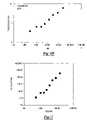
- FIG. 7is a representative plot for calculating molecular weights from a flow detector response in accordance with the present invention.
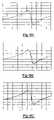
- FIGS. 8A-8Care illustrative traces for comparison that are obtainable in accordance with the present invention.
- FIGS. 9A-9Care additional illustrative traces for comparison that are obtainable in accordance with the present invention.
- the present inventioncontemplates methods, devices and systems for determining a characteristic of a sample of a material, and preferably in a rapid, high-throughput manner.
- the methods of the present inventionare premised upon a workflow that includes steps of (A) preparing the sample for analysis (which may further include a suitable dilution), (B) injecting the sample into a mobile phase of a flow characterization system (e.g., a chromatography system or a flow-injection analysis system), (C) optionally separating the sample chromatographically, (D) detecting a property of the sample or of a component thereof, and/or (E) correlating the detected property to a characterizing property of interest.
- a flow characterization systeme.g., a chromatography system or a flow-injection analysis system
- Coptionally separating the sample chromatographically
- Ddetecting a property of the sample or of a component thereof
- Ecorrelating the detected property to a characterizing property of interest.
- characterization protocolsmay be employed involving some or all of the aforementioned steps.
- a property of a samplemay be detected in a non-flow, static system either with preparation (steps A and D) or without preparation (step D).
- a property of a samplemay be detected in a flow characterization system—either with or without sample preparation and either with or without chromatographic separation.
- characterization protocols involving flow characterization systems without chromatographic separationa property of a sample may be detected in a flow-injection analysis system either with preparation (steps A, B and D) or without preparation (steps B and D).
- a property of the samplemay be detected in a chromatography system either with preparation (steps A, B, C and D) or without preparation (steps B, C and D). While the detected property from samples being screened can be compared and ranked relative to each other on the basis of their performance, they could also be analyzed for absolute values (e.g., using a reference or calibration standard).
- the devices and systems of the present inventionmay be employed in connection with performance of the above workflow.
- the devices and systems of the present inventionare predicated upon the combination of a flow injection analysis instrument or chromatographic analysis instrument with a detector comprising a mechanical resonator, more particularly a mechanical resonator that is operated at a frequency of less than about 1 MHz, more preferably up to about 500 kHz, and even still more preferably up to about 250 kHz; for example, it is operated from about 1 to about 500 kHz, and more preferably in the range of about 5 to about 250 kHz, and still more preferably in the range of about 10 to about 100 kHz (e.g., about 28 to about 32 kHz). Further details of a preferred construction are described herein, together with illustrative examples.
- a method for characterizing a fluid samplecomprising the steps of injecting a fluid sample (e.g., liquid, gas or otherwise) into a mobile phase of a chromatography system (e.g., liquid, gas or otherwise), chromatographically separating at least one sample component of the fluid sample from other sample components thereof, and detecting a property of the fluid sample or of a component thereof with a flow detector comprising a mechanical resonator, with the preferred mechanical resonator including a torsional resonator, a flexural resonator or a combination thereof, such as a tuning fork resonator, and wherein the resonator is preferably operated at a frequency of less than about 1 MHz, more preferably up to about 500 kHz, and even still more preferably up to about 250 kHz; for example, it is operated from about 1 to about 500 kHz, and more preferably in the range of about 5 to about 250 kHz, and
- Another preferred method for characterizing a fluid samplecomprises the steps of injecting a fluid sample into a mobile phase of a flow-injection analysis system, advancing the injected fluid sample to a flow detector without substantial chromatographic separation thereof, and detecting a property of the fluid sample or of a component thereof with the flow detector, with the flow detector comprising an above described preferred mechanical resonator, operated at the above frequencies.
- the property of the fluid sample or a component thereofis detected by a method that comprises allowing the mobile phase comprising the sample or a component thereof to flow past the mechanical resonator, such that the sample or a component thereof contacts the resonator during a detection period, applying an input signal at one or more input frequencies to a circuit coupled with the resonator to oscillate the resonator during the detection period, measuring the frequency response of the resonator during the detection period, and determining a property of the sample or a component thereof from the measured frequency response.
- the input signalmay be applied at a substantially constant frequency during the detection period, or at two or more frequencies during the detection period. Further, the property of the sample or component thereof may be determined from the measured frequency response by comparison to a calibration curve showing the measured frequency response at that input frequency for two or more known samples.
- the input signalmay also comprise a variable frequency input signal, and thus the method further comprises varying the frequency of the input signal over a predetermined frequency range during the detection period, such that a frequency-dependent response of the resonator can be measured.
- the predetermined frequency rangeis determined by a method that comprises determining the resonance frequency of the mechanical resonator while the resonator is in flow contact with the mobile phase.
- the methodmight further comprise varying the frequency of the input signal over a predetermined frequency range for a first frequency scan during a first portion of the detection period, such that a frequency-dependent response of the resonator can be measured during the first portion of the detection period, varying the frequency of the input signal over the predetermined frequency range for a second frequency scan during a second portion of the detection period, such that a frequency-dependent response of the resonator can be measured during the second portion of the detection period, varying the frequency of the input signal over the predetermined frequency range for a third frequency scan during a third portion of the detection period, such that a frequency-dependent response of the resonator can be measured during the third portion of the detection period, and determining a property of the sample or a component thereof from the measured frequency response during each of the first, second and third portions of the detection period.
- Frequency scan ratemay be the same or vary.
- the first, second and third frequency scansmay be effected at an overall average frequency scan rate of not less than about one, or possibly even three or more, five or more, or even ten or more frequency scans per second.
- the composition of any mobile phasemay vary or remain substantially constant over time.
- the frequency of the input signal over timemay be varied to compensate for any such variation in mobile-phase composition.
- the flow detector of the present inventionmay comprise two or more mechanical resonators, which may be the same or different relative to each other. It is thus possible that the mobile phase can be allowed to flow past each of the two or more resonators such that the sample or component thereof contacts each of the two or more resonators during the detection period.
- the input signal for each of the two or more resonatorsmay be applied at a common, constant frequency during the detection period, or at different, constant frequencies during the detection period.
- the input signal for one or more of the two or more resonatorsis a variable frequency input signal
- a preferred methodfurther comprises varying the frequencies of the input signals over a common predetermined frequency range, over different predetermined frequency ranges during the detection period, or a combination thereof, such that a frequency-dependent response can be measured for each of the two or more resonators during the detection period.
- the preferred flow detector of the present inventioncomprises a mechanical resonator placed in a fluid passageway (e.g., for defining a detection cavity), an inlet for providing fluid communication between the detection cavity and a mobile phase source, and an outlet for providing fluid communication between the detection cavity and a mobile phase sink.
- a fluid passagewaye.g., for defining a detection cavity
- an inletfor providing fluid communication between the detection cavity and a mobile phase source
- an outletfor providing fluid communication between the detection cavity and a mobile phase sink.
- the present inventioncan be employed with a flow characterization instrument (e.g., a chromatograph or flow injection analyzer) that is operated using art-disclosed serial (e.g., consecutive sequence) or parallel (e.g., simulataneous) techniques, such as for sample injection, sample separations, input signal generation, signal monitoring, or other property detection of two or more samples, using one or more detectors.
- a flow characterization instrumente.g., a chromatograph or flow injection analyzer
- art-disclosed serial (e.g., consecutive sequence) or parallel (e.g., simulataneous) techniquessuch as for sample injection, sample separations, input signal generation, signal monitoring, or other property detection of two or more samples, using one or more detectors.
- a chromatography instrumentinclude a column comprising a separation cavity, an inlet port for receiving a mobile phase and for supplying a sample to the separation cavity, an effluent port for discharging the mobile phase and the sample or separated components thereof from the separation cavity, and a stationary-phase within the separation cavity, a mobile phase source in fluid communication with the inlet port of the chromatographic column for providing a mobile phase thereto, an injection valve adapted to provide for selective fluid communication with the mobile phase for injecting samples into the mobile phase, and a resonator flow detector in fluid communication with the effluent port of the chromatographic column for detecting a property of the sample or a component thereof.
- a suitable flow injection analysis instrumentpreferably includes a flow conduit, optionally in fluid communication with a flow column, the flow conduit and optional flow column each having an essential absence of chromatographic separation media, a mobile phase source in fluid communication with the flow conduit and optional flow column, for providing a mobile phase thereto, an injection valve adapted to provide for selective fluid communication with the mobile phase for injecting samples into the mobile phase, and a resonator flow detector in fluid communication with the flow conduit and optional flow column, for detecting a property of the sample or a component thereof.
- a suitable flow injection analysis instrumentpreferably includes a flow conduit, optionally in fluid communication with a flow column, the flow conduit and optional flow column each having an essential absence of chromatographic separation media, a mobile phase source in fluid communication with the flow conduit and optional flow column, for providing a mobile phase thereto, an injection valve adapted to provide for selective fluid communication with the mobile phase for injecting samples into the mobile phase, and a resonator flow detector in fluid communication with the flow conduit and optional flow column, for detecting a property of the sample or a component thereof.
- a preferred system 100 of the present inventionincludes a resonator flow detector 102 adapted to be placed in fluid communication with the sample (or components thereof) either upstream of, downstream of, or both, any chromatography column, flow injector, or effluent port.
- a resonator flow detector 102adapted to be placed in fluid communication with the sample (or components thereof) either upstream of, downstream of, or both, any chromatography column, flow injector, or effluent port.
- FIG. 1illustrates placement of the resonator detector in a system in which an optional, suitable separation component 104 (e.g., an elongated chromatography column such as one having approximate dimensions of about 30 cm ⁇ 7 mm, or available under the designation PL-Gel Mixed-B from Polymer Laboratories) has been inserted between a flow system 106 (e.g., including a pump 108 , an auto-sampler 110 , or one or more additional or alternative components) and the flow detector 102 .
- An optional evaporative light scattering detector (ELSD) or other optional suitable detector 112is connected directly or indirectly to an outlet of the flow detector 102 .
- ELSDevaporative light scattering detector
- the flow detector 102is also preferably coupled with suitable hardware 114 for generating, receiving or a combination thereof, a signal for any resonator housed in the flow detector 102 .
- suitable hardware 114for generating, receiving or a combination thereof, a signal for any resonator housed in the flow detector 102 .
- a lock-in amplifiere.g., of a type such as an SR830 (or possibly an SR 810 or 850) DSP Lock-In Amplifier from Stanford Research Systems
- SR830or possibly an SR 810 or 850 DSP Lock-In Amplifier from Stanford Research Systems
- Any of a number of suitable hardware devicesmay be employed, as the skilled artisan with appreciate, particularly with reference to commonly-owned patent properties, including, for example, the subject matter shown in U.S. Pat. Nos.
- one or both of the resonator flow detector 102 , and any other detector 112 that might optionally be employed,are in direct or indirect signaling communication with a suitable processor 115 , such as a personal computer, and preferably one that includes software that functions for one or a combination of setting-up instrument parameters, controlling instrument parameters, running analyses, generate results, storing results, organizing results, or publishing data reports (e.g., a PC employing MILLENIUMTM data management software, such as is commercially available from Waters Corporation of Milford, Mass.).
- a suitable processor 115such as a personal computer, and preferably one that includes software that functions for one or a combination of setting-up instrument parameters, controlling instrument parameters, running analyses, generate results, storing results, organizing results, or publishing data reports (e.g., a PC employing MILLENIUMTM data management software, such as is commercially available from Waters Corporation of Milford, Mass.).
- a flow detector of the present inventionincludes an inlet portion, a detection portion (such as, for example, including a flow passageway in which the resonator is at least partially located), and an outlet portion.
- the inlet portionis adapted for fluid communication with the flow characterization system (e.g., downstream from the separation component), and the outlet portion is adapted for fluid communication with any additionally serially configured detector, a waste collection system, or the like.
- the flow detectorincludes a suitable housing or frame for enclosing or otherwise holding any electrical components or other hardware associated with the detector.
- the detector 102includes a detector head 116 having a passageway 118 defined therein for providing a sample flow path.
- the passagewayis adapted for receiving and holding a resonator 120 in sensing relation to any sample that passes through the passageway.
- the detectorwill include at least one or a combination of a suitable inlet conduit (e.g. inlet capillary) 122 , or a suitable outlet conduit (e.g. outlet capillary) 124 .
- a housing 126is optionally provided, which can be assembled together with the head 116 , such as by the use of fasteners 128 that are received in apertures 130 .
- the housing functionmight be performed by suitable structure fabricated in the detector head itself (e.g., combining the head with the housing), so as to reduce the number of overall components. It will be appreciated that even though one preferred approach is to arrange the inlet and outlet conduits generally orthogonally relative to each other, other orientations are also possible, such as directly in line with each other, parallel to each other, at an acute angle relative to each other, at an obtuse angle relative to each other, forming one or more curves relative to each other or otherwise.
- the detection cell 132may be any suitable size or shape and preferably it has an internal volume of about 1 to about 500 microliters and more preferably about 5 to about 50 microliters, e.g. about 15 microliters.
- the detection cell 132may include some or all of the passageway 118 . It is possible that the entirety of the passageway defines the detection cell 132 .
- One or a plurality of leads 134 associated with the resonator 120preferably are connected to the signaling hardware of the present invention.
- one preferred approachis for any lead 134 to penetrate a wall of the housing and then connect with suitable cables. This may be done in any suitable manner.
- one or more connectorssuch as a bayonet nut connector (BNC) 136 , are attached to the housing 126 , for affording ease of connection with additional hardware.
- BNCbayonet nut connector
- datais acquired using the lock-in amplifier, preferably in combination with a suitable network analyzer.
- a network analyzercan be used to identify the frequency of resonation of one or more resonators of the present flow detector, as well as to find a frequency that is most sensitive to the changes in the viscosity of eluent.
- an analog signalis generated by the lock-in amplifier, which is preferably tuned to a frequency below about 1 MHz, more preferably below about 500 kHz, and even still more preferably below about 250 kHz; for example, it is tuned to a frequency of from about 1 to about 500 kHz, and more preferably in the range of about 5 to about 250 kHz, and still more preferably in the range of about 10 to about 100 kHz (e.g., to a frequency of about that of the resonator, e.g., about 28.10 kHz), and even more preferably slightly above or below (e.g., within about 50% of the frequency and more preferably within about 25% of the frequency of resonance of a preferred tuning fork resonator).
- a preferred tuning for resonatoris that available commercially from Citizen Corporation tuning fork, under part number CFS308-32.768KDZFB.
- Other tuning fork resonatorsmay also be employed.
- a tuning fork resonator available from ESC(Taiwan), part # ESC-.327-8-14 may be used.
- a preferred tuning fork resonator hereinwill include two or more substantially elongated forks or tines joined at a first common end through a common member, each of the two or more forks having two primary surfaces in substantially parallel opposition to each other, two edge surfaces in substantially parallel opposition to each other, and a second free end surface substantially opposed to the first common end.
- the resonatormay be orientated in the flow detector such that the direction of bulk mobile phase flow is substantially parallel to the primary surfaces of the forks. It is also possible that the direction of bulk mobile phase flow is substantially normal to the primary surfaces of the forks. Other intermediate angular orientations are also possible.
- torsional or flexural resonator detectors, and especially tuning fork detectorsare particularly preferred for use in the present invention for a number of reasons, including for instance that tuning fork detectors are suitable for construction with relatively smaller dead volumes, as compared with a typical viscometric detector (e.g., less than about 75 microliters, more preferably less than about 50 microliters, and still more preferably less than about 20 microliters, as compared with typical volumes of about 100 uL for the most efficient viscometric detectors believed to be presently commercially available).
- the tuning fork detectorsare thus capable of and indeed produce relatively sharper peaks and higher resolution power as compared with such existing detectors.
- the preferred resonator detectors of the present inventionwill generally be operated under resonance conditions such that any acoustic wave generation from the resonator is substantially avoided for substantially the entirety of the volume of sample that is flowed over the resonator.
- the resonatoris placed in signaling communication with (e.g., connected with a short cable, or otherwise in electrical, magnetic, optical, thermal, or other communication) to an input of the lock-in amplifier, and more preferably to a high impedance input of the lock-in amplifier (e.g., of about 0.1 to about 5 megaOhm and about 1 to about 100 pF, and more preferably about 2 megaohm and 20 pF).
- signaling communication withe.g., connected with a short cable, or otherwise in electrical, magnetic, optical, thermal, or other communication
- a high impedance input of the lock-in amplifiere.g., of about 0.1 to about 5 megaOhm and about 1 to about 100 pF, and more preferably about 2 megaohm and 20 pF.
- the lock-in amplifieris preferably operated in an output offset mode and with the expansion of the output at a magnitude on the order of at least about 10 times, and more preferably about 100 times.
- a suitable amplifier output channele.g., the “R” channel output of the amplifier
- which is the amplitude of the detected signalis suitably connected (e.g., via a SAT/IN box coupled with a BusLace board) to the computer 115 , preferably equipped with the data management software discussed previously.
- the hardware of the present inventionin one aspect, is secured in a fixed location. It will be appreciated, however, that the components may be translatable relative to each other as well. It may also be possible to employ a suitable robot arm (e.g., such as that available from Tecan Systems (formerly Cavro Scientific Instruments)(San Jose, Calif.)) for translating the hardware components and sample relative to each other.
- a suitable robot arme.g., such as that available from Tecan Systems (formerly Cavro Scientific Instruments)(San Jose, Calif.)
- viscosity, density, dielectric field or another propertycan be monitored directly or derived from a measurement, such as by calculation, from the flow detector in accordance with the above by any of a number of different approaches.
- the monitoring that occursmay be monitoring the change of frequency of the resonator while maintaining the input signal to the resonator as a constant. It may alternatively employ the monitoring of the change in electrical feedback from the resonator while maintaining a constant frequency.
- the input signalis a variable frequency input signal and the monitoring includes varying the frequency of a variable frequency input signal over a predetermined frequency range to obtain a frequency-dependent resonator response of the mechanical resonator.
- the measured responsecan then be correlated with viscosity, density, dielectric field or another property using art-disclosed methods. For instance, relative sample performance might be analyzed and compared with each other. Absolute measures might also be taken, such as by measuring responses and comparing them against responses obtained from know reference or calibration standards.
- absolute valuesare obtained for a particular property such as viscosity, molecular weight, concentration or a combination thereof.
- a particular propertysuch as viscosity, molecular weight, concentration or a combination thereof.
- one preferred approachis to monitor the resonator detector response for one or a plurality of reference or calibration standards having known property values.
- the datacan be correlated for corresponding a particular detector response with a known property.
- a plotmay be prepared against which later data obtained for samples of unknown property can be compared. This can be performed manually, with a computer, by plots, calculation or otherwise.
- a suitable molecular weight dependent propertysuch as viscosity can be calculated using an equation that correlates viscosity as a function of molecular weight, such as the Mark-Houwink Equation.
- one or more propertiesmay be derived from a second detector, which is adapted for the purpose of measuring and providing data about a property.
- datamight be obtained from a mass detector (e.g., an ELSD), and such data employed in combination with data obtained from the resonator flow detector of the present invention. Accordingly, the present invention contemplates performance of any or all of the above techniques.
- measurements taken in accordance with the present inventionmay be taken continuously (e.g., as real-time), in spaced intervals, or a combination of both.
- the mobile phasepreferably is employed at a flow rate ranging from about 0.01 mL/min to about 100 mL, and more preferably about 0.1 to about 10 mL/min (e.g., about for a THF mobile phase, or the like, a flow rate of about 1 mL/min).
- a flow rateranging from about 0.01 mL/min to about 100 mL, and more preferably about 0.1 to about 10 mL/min (e.g., about for a THF mobile phase, or the like, a flow rate of about 1 mL/min).
- other operational parameterscan also be successfully employed using the teachings herein.
- it may be attractive to employ a variable flow mode or stop flow modein accordance with art-disclosed teachings such as are found in U.S. Pat. No. 6,175,409, hereby incorporated by reference.
- a particularly preferred flow characterization systemis a chromatograph (e.g., comprise, for instance, one or a plurality of injection valves or injection loops, injection ports, chromatographic columns, or effluent ports) that is preferably suitably equipped with a pump, optional solvent degasser, and optional autosampler (e.g., a robotic auto-sampler having one or a plurality of robot arms, and optional heated probes).
- a pumpoptional solvent degasser
- autosamplere.g., a robotic auto-sampler having one or a plurality of robot arms, and optional heated probes.
- One or a plurality of detectorspreferably are located upstream of the effluent port.
- Any suitable chromatograph devicemay be used, and the device may be adapted for HPLC, GPC or another form of chromatography.
- An example of one preferred commercially available device useful in the present inventionis that available from Waters Corporation of Milford, Mass., under the name AllianceTM HPLC.
- a suitable detectormay be an ELSD detector commercially available from Polymer Laboratories, such as the PL-ELS 1000 evaporative light scattering detector. It will be appreciated that other devices may also be employed.
- a mobile-phase fluidis pumped from a mobile-phase reservoir by a pump through the injection valve, chromatographic column and detector.
- the pumpcan be controlled with a microprocessor.
- the mobile phasecan be exhausted from the system via effluent port into a waste collection container.
- a sampleis loaded into an injection valve through an injection port, and the loaded sample is injected into the mobile phase of the chromatographic system.
- the injected sampleis chromatographically separated in the chromatographic column.
- a property of the sample, one or more separated components thereof, or both,is then detected while the sample resides in the detector.
- a microprocessore.g., computer
- a microprocessoris typically in electronic communication with the detector to collect, process and analyze the data obtained therefrom. While the same microprocessor can be used for the pump control and data acquisition, these functions could be effected with separate microprocessors.
- the geometry of the separation columns employed hereinmay be selected as desired.
- conventional columnsmay be employed, such as those that are relatively long and narrow (e.g., ranging from about 4-8 mm in diameter and from about 30-50 cm in length, respectively).
- the use of shorter and wider columnsis also possible.
- An example of a preferred commercially available columnis a GPC column (30 cm ⁇ 7 mm PL-Gel Mixed-B, available from Polymer Laboratories) Under any approach, one or a plurality of columns (e.g., three or four columns) may be employed in series for each separation.
- the chromatographic columntypically comprises a separation medium having a stationary-phase within a separation cavity, either with or without an inert support for the stationary phase.
- the columncan also comprise one or more fillers, frits, fittings and or other desired features appropriate for its intended application.
- the particular separation medium to be employed as the stationary-phaseis not critical.
- Typical stationary-phase mediacan be a bed of packed beads, rods or other shaped-particles, or a monolithic medium (typically greater than about 5 mm in thickness).
- a preferred stationary-phaseincludes a porous media, such as are suitable for gel permeation chromatography (GPC), or media suitable for precipitation-redissolution chromatography, adsorption chromatography, and/or reverse-phase chromatography.
- Non-porous particles or empty columns and/or capillaries with adsorptive wallscan be used as well. If beads are employed, spherical beads are preferred.
- particularly preferred stationary-phase mediamay be selected from silica, cross-linked resins, hydroxylated polyglycidyl methacrylates,(e.g., poly(2-3-dihydroxypropylmethacrylate)), poly(hydroxyethyl methacrylate), polystyrenic polymers such as poly(styrene-divinylbenzene), or the like.
- the mobile-phase fluid employedis also not generally critical, and can vary depending on the chemistry of the separation being effected.
- An exemplary mobile-phase fluidmay include one or more of tetrahydrofuran (THF), toluene, dimethylformamide, water, aqueous buffers, trichlorobenzene and dichlorobenzene.
- Exemplary mobile-phase fluids for precipitation-redissolution chromatographyinclude THF, methanol, hexane, acetone, acetonitrile and water.
- the mobile phasecan include, for example, hexane, isooctane, decane, THF, dichloromethane, chloroform, diethylether, acetone or combinations thereof.
- a flow characterization systemmight employ a separation.
- some analysis systemscan include an apparatus for non-chromatographic separations (e.g., filtration).
- a samplecan be prepared, prior to analysis, by separating one or more components of the raw sample from other components thereof using any suitable art-disclosed technique.
- the flow characterization systemscan include additional reservoirs, and additional pumps to provide more than one mobile-phase fluid, to provide a mobile-phase composition gradient or even to provide a mobile-phase phase temperature gradient.
- the type of chromatographyis not limited to the preferred embodiments shown, but that the flow detector devices of the present invention may be used in any of a number of different types of chromatography including, for example, one or a combination of art-disclosed precipitation-redissolution chromatography, size exclusion chromatography, liquid chromatography, adsorption chromatography, reverse-phase chromatography, or gel permeation chromatography techniques.
- a flow characterization system of the present inventionmay include one or more additional detectors, for use alone or in combination with the resonator flow detector of the present invention, such as a suitable flow-injection mass detector or other suitable detector (e.g., one or more of an evaporative light scatter detector, a dynamic light-scattering detector, a static light-scattering detector, an evaporative mass detector, a refractive index detector, capillary-viscometric detector, photodiode array detector, infra-red detector, fluorescence detector, electrochemical detector, conductivity detector, ultraviolet-visible absorbance detector or the like).
- the systemmay optionally be calibrated using calibration standards having known properties. “Universal” standard practices may be employed, as may “indirect calibration standards”.
- a flow detectoraccording to the present invention is particularly advantageous for the purpose of monitoring viscosity of a sample that is passed through the flow characterization system. As will also be discussed herein, it also may be suitably employed for measuring concentration, molecular weight, dielectricity, density or other related properties.
- resonatorand operation thereof for detecting various properties are described in the aforementioned Mechanical Oscillator Patents and Applications.
- a resonator flow detector in accordance with the present inventioncomprises a single mechanical resonator. It is also possible that a plurality of different resonators may be combined into a single detector, or a plurality of different resonators be separated into a plurality of detectors.
- the input signalcan be applied at a single, substantially constant frequency.
- the single, substantially constant frequencyis preferably a predetermined frequency that is the resonance frequency for the mechanical resonator under the analysis conditions (e.g., in that mobile phase, at that flow-rate, with that type of sample, etc.).
- differences in measured response frequencies and/or changes in measured response frequenciescan be used to provide meaningful information about the sample being analyzed—even if absolute values for the property are not determined.
- a property of the sample or component thereofcan be determined from a measured frequency response curve by comparing the measured frequency response to a calibration curve.
- the calibration curvecan include values of the measured frequency response at that input frequency for known samples, for example, for known samples evaluated in the same mobile phase.
- the input signalcan be applied at two or more different frequencies during the detection period.
- the input signalis preferably a variable frequency input signal.
- the frequency of the input signalcan be varied, preferably over a predetermined frequency range, during the detection period, such that a frequency-dependent response of the resonator can be measured.
- the predetermined frequency rangecan be a range of frequencies surrounding the resonance frequency of the mechanical resonator while the resonator is in flow contact with the mobile phase.
- the frequency rangecan vary, for example, as about ⁇ 20% of the resonance frequency, or preferably about ⁇ 10% of the resonance frequency.
- differences in measured response frequencies and/or changes in measured response frequenciescan be used to provide meaningful information about the sample being analyzed, including absolute values for the property being determined.
- a property of the sample or component thereofcan also be determined from a measured frequency response curve by comparing the measured frequency response to a calibration curve.
- the calibration curvecan include values of the measured frequency responses over the range of input frequencies for known samples, for example, for known samples evaluated in the same mobile phase.
- a single sample or sample component(e.g., single separated component of an HPLC system) can be evaluated by effecting multiple scans over the sample during the detection period, with each scan covering a range of frequencies. More specifically, the frequency of the input signal can be varied over a predetermined frequency range for a first frequency scan during a first portion of the detection period, such that a frequency-dependent response of the resonator can be measured during the first portion of the detection period. Thereafter, the frequency of the input signal can be varied over the predetermined frequency range for a second frequency scan during a second portion of the detection period, such that a frequency-dependent response of the resonator can be measured during the second portion of the detection period.
- the frequency of the input signalcan be varied over the predetermined frequency range for a third frequency scan during a third portion of the detection period, such that a frequency-dependent response of the resonator can be measured during the third portion of the detection period.
- the property of the sample or a component thereofis determined from the measured frequency response during each of the first, second and third and/or additional portions of the detection period.
- the rate of scanning in this embodimentis not narrowly critical, but can be described as follows.
- the first, second and third frequency scansare effected at an overall average frequency scan rate of not less than about one frequency scan per second, at an overall average frequency scan rate of not less than about three frequency scans per second, and more preferably at an overall average frequency scan rate of not less than about ten frequency scans per second.
- the size of the injected sample and the mobile phase flow ratecan be controlled such that five or more frequency scans of the sample or components thereof are effected during the detection period, and preferably, such that ten or more frequency scans of the sample or components thereof are effected during the detection period.
- a first resonator flow detectormay be employed in parallel or serially upstream or downstream of a second or additional resonator flow detector and the resonators therein operated at the same or a different frequency relative to each other.
- a first resonator flow detectormay be employed upstream of a separation column and a second or further additional resonator flow detector employed downstream of the separation column, with the resonators therein operated at the same or a different frequency relative to each other.
- the preferred resonators or oscillators for the detectors hereinare intended to include mechanical piezoelectric resonators, and particularly quartz resonators.
- a highly preferred mechanical resonator for employment hereinis a flexural resonator such as a tuning fork resonator, which offers an advantage of being able to be oscillated at a relatively low frequency range (e.g., in a preferred embodiment, it is operated in the range of less than about 1 MHz, more preferably up to about 500 kHz, still more preferably about 1 to about 100 kHz, (e.g., about 32 kHz)).
- the resonators of the present inventionare also selected so that they will not excite acoustic waves in a sample of sufficient magnitude that the measurements would be compromised.
- the present inventionis not intended to be limited to tuning fork resonators.
- Other types of resonatorscan be used, such as thickness shear mode resonators, tridents, cantilevers, torsion bars, bimorphs, membrane resonators, length extension resonators, torsion resonators, unimorphs, or various surface acoustic wave devices, or combinations thereof. More preferred resonators are selected from tuning forks (e.g., two-tine, tridents or the like), cantilevers, bimorphs, or unimorphs.
- tuning forkse.g., two-tine, tridents or the like
- cantileversbimorphs, or unimorphs.
- a plurality of the same type or different types of resonators of resonatorscan be used in combination. For example, a low frequency resonator may be employed with a high frequency resonator. In this manner, it may be possible to obtain a wider range of responses for a given sample.
- a tuning fork hereinis an excellent candidate for providing a detector for measuring small amounts of mass change in a flow characterization system.
- the resonance frequency and the damping of the tuning fork resonatordepends on the effective mass of a tine and the amount of “drag” of the tine in contact with a sample, any change in the mass on the tine mass or the amount of drag will change the resonance response of the tuning fork.
- An increase in the mass associated with the tuning forkwill therefore reduce the resonance frequency of the tuning fork in a measurable way.
- any resonator used hereinoptionally may be coated with a material to change the performance characteristics of the resonator.
- the materialcan be a coating, such as to protect the resonator from corrosion or other factors potentially affecting resonator performance.
- itmay be a specialized “functionalization” coating that changes the resonator's response if a selected substance is present in the composition being tested by the resonator. For example, adding a hydrophobic or hydrophilic functionality to a tuning fork tine allows the tine to attract or repel selected substances in the medium being analyzed, changing the mass or effective mass of the tuning fork and thereby changing its resonance frequency.
- the resonatorscan also be functionalized with a polymer layer or other selective absorbing layer to detect the presence of specific molecules in a vapor.
- the coating or functionalitycan be applied onto the resonator using any known method, such as spraying or dipping. Further, the specific material selected for the coating or functionality will depend on the specific application in which the tuning fork resonator is to be used. J. Hlavay and G. G. Guilbault described various coating and functionalization methods and materials to adapt piezoelectric crystal detectors for specific applications in “Applications of the Piezoelectric Crystal Detector in Analytical Chemistry,” Analytical Chemistry, Vol. 49, No. 13, November 1977, p. 1890, incorporated herein by reference.
- a single tuning fork resonatormay be coated or functionalized.
- multiple resonators having the same or a different structure, the same or different coatings and/or the same or different functionalitiescan be incorporated into one sensor.
- a plurality of tuning fork resonatorsmay have the same structure but have different functionalities, each functionality designed to, for example, bond with a different target molecule.
- one tuning fork resonatorcan, for example, be functionalized with a material designed to bond with a first substance while another resonator can be functionalized with a material designed to bond with second substance. The presence of either one of these substances in the sample composition being tested will cause the corresponding tuning fork resonator to change its resonance frequency.
- the flow detectorcan comprise a detector that comprises two or more mechanical resonators.
- the mechanical resonatorscan be the same or different, with respect to design and/or performance, and in some embodiments, are preferably substantially the same.
- the two or more resonatorscan be operated at one or more common, substantially constant input frequencies, or at two or more different, substantially constant input frequencies.
- one of the resonatorscan be operated at a single, substantially constant input frequency, while another of the two or more resonators are operated at two or more variable frequencies.
- both of the two or more resonatorscan be operated at variable input frequencies, over the same ranges or over different ranges of frequencies.
- the present inventionis disclosed, in one preferred aspect, as a screening technique as part of a combinatorial research program (e.g., for a polymer research or production program in which extent of dissolution must be measured, the presence or absence of targets identified or otherwise), it has other applications, including but not limited to the provision of a detector for measuring quantities (e.g., relatively small quantities) in a commercial (rather than a research) environment, such as a real time or an on-line process monitoring, process control or other quality control measure in which a flow characterization system is employed.
- quantitiese.g., relatively small quantities
- a commercial environmentsuch as a real time or an on-line process monitoring, process control or other quality control measure in which a flow characterization system is employed.
- Examples of the various applications to which the present invention is particularly suitedinclude, without limitation, detecting viscosity (e.g., intrinsic, relative, specific, or a combination thereof), molecular weight, molecular weight distribution, branching coefficient, or the like.
- methods of the present inventionalso contemplate the operation of the present systems in the latter mentioned applications.
- the present inventionlends itself particularly well for bulk property measurements, such as may be necessary, for example, for monitoring polymer properties.
- a large compositional spacee.g., of variable structures or ratios of components
- a large reaction condition spacee.g., of temperature, pressure, humidity or reaction time
- the librariesmay be synthesized or screened on a common substrate or two or more different substrates.
- the number of samples that can be analyzed as part of a combinatorial research programis not limited herein.
- the number of samplescan be 4 or more, 20 or more, 100 or more, 150 or more, 400 or more, 500 or more, 750 or more, 1,000 or more, 1,500 or more, 2,000 or more, 5,000 or more and 10,000 or more samples.
- the number of samplescan be 96*N, where N is an integer ranging from about 1 to about 100. For many applications, N can suitably range from 1 to about 20, and in some cases, from 1 to about 5.
- sample sizeis not narrowly critical, it can generally vary, depending on the particular characterization protocols and systems used to characterize the sample or components thereof. Typical sample sizes can range from about 0.1 microliter to about 1 ml, more typically from about 1 microliter to about 1000 microliters, even more typically from about 5 microliters to about 100 microliters, and still more typically from about 10 microliters to about 50 microliters.
- a generally preferred sample size for flow characterization systems and, particularly for liquid chromatographyis a sample size of about 20 microliters.
- Samples within a librarymay differ, including with regard to chemical structure, processing or synthesis history, mixtures of interacting components, post-synthesis treatment, purity, etc.
- the number of samples included within the librarycan generally be the same as the number of samples included within the plurality of samples, as discussed above. In general, however, not all of the samples within a library of samples need to be different samples.
- the librariesmay contain only one type of sample. Typically, however, for combinatorial research applications, at least two or more, preferably at least four or more, even more preferably eight or more and, in many cases most, and allowably each of the plurality of samples in a given library of samples will be different from each other.
- a different samplecan be included within at least about 50%, preferably at least 75%, preferably at least 80%, even more preferably at least 90%, still more preferably at least 95%, yet more preferably at least 98% and most preferably at least 99% of the samples included in the sample library. In some cases, all of the samples in a library of samples will be different from each other.
- the samplesare spatially separated, such that members of the library of samples are separately addressable. All samples in a library may be the same or different relative to each other. When process conditions are to be evaluated, for example, the libraries may contain only one type of sample. The use of reference standards, controls or calibration standards may also be performed, though it is not necessary.
- the samples of a librarymay be previously characterized, uncharacterized or a combination thereof, so that property information about the samples may not be known before screening.
- Combinatorial approaches for screening a librarycan include an initial, primary screening, in which material samples are rapidly evaluated to provide valuable preliminary data and, optimally, to identify several “hits”—particular candidate samples having characteristics that meet or exceed certain predetermined metrics (e.g., performance characteristics, desirable properties, unexpected and/or unusual properties, etc.).
- certain predetermined metricse.g., performance characteristics, desirable properties, unexpected and/or unusual properties, etc.
- libraries focused around the primary-screen hitsmight be further evaluated with a secondary screen—a screen designed to provide (and typically verified, based on known materials, to provide) chemical composition, sample content or process conditions that relate with a greater degree of confidence to commercially-important important processes and conditions than those applied in the primary screen.
- a secondary screena screen designed to provide (and typically verified, based on known materials, to provide) chemical composition, sample content or process conditions that relate with a greater degree of confidence to commercially-important important processes and conditions than those applied in the primary screen.
- Particular samples that surpass the predetermined metrics for the secondary screenmay then be considered to be “leads.”
- identified lead samplesmay be subsequently prepared in bulk scale or otherwise developed for commercial applications through traditional bench-scale and/or pilot scale experiments.
- the present inventionis not limited to the performance of a single characterization, but may include a plurality of different characterization steps relative to a sample of interest.
- two or more characterization systemscan be used to screen each of a plurality of samples for two or more properties of interest—one property being determined by a first detector, another property being determined by a second or additional detector.
- a first characterization systemcan be used to prescreen each of a plurality of samples for a first property of interest, and then a second characterization system can be used to rescreen certain selected samples—for the same or for a different property of interest—with the selection for the second screen being based on results from the first prescreening.
- a figure of meritis determined for the four or more samples.
- the figure of meritis preferably based, at least in part, on the first determined property of interest.
- the determined figure of merit for the four or more samplesis compared with a predetermined threshold value for the figure of merit.
- the threshold valuecan be based, for example, on results with a then-best-known system.
- Those samples of the four or more samples that favorably compare with the predetermined threshold value for the figure of meritare then screened with the second characterization system. In a preferred embodiment, only those samples that favorably compare to the predetermined figure of merit are screened with the second characterization system.
- a resonator detectoris used alone (e.g., in a flow characterization instrument with or without chromatographic separation) or in combination with one or more serially-configured, parallel-configured other detectors such as one or more of an evaporative. light scatter detector, a dynamic light-scattering detector, a static light-scattering detector, an evaporative mass detector, a refractive index detector, capillary-viscometric detector, photodiode array detector, infra-red detector, fluorescence detector, electrochemical detector, conductivity detector, ultraviolet-visible absorbance detector or the like.
- the present inventionmay also be employed by itself or in combination with other screening protocols for sample analysis.
- the present inventioninvolves measuring a first characteristic of a sample in combination with at least one or a plurality of additional other characterization steps, such as X-ray analysis, chromatography, mass spectrometry, optical screening, infrared screening, electrochemical screening, mechanical property screening, or the like.
- additional other characterization stepssuch as X-ray analysis, chromatography, mass spectrometry, optical screening, infrared screening, electrochemical screening, mechanical property screening, or the like.
- examples of other screening techniqueswhich might be combined with the analysis of the present invention, include those addressed in commonly-owned U.S. Pat. Nos.
- a property of each of the samples or of one or more components thereofis detected—serially or in a parallel, serial-parallel or hybrid parallel-serial manner—at an average sample throughput of not more than about 10 minutes per sample.
- average sample throughputrefers to the sample-number normalized total (cumulative) period of time required to detect a property of two or more polymer samples with a characterization system. The total, cumulative time period is delineated from the initiation of the characterization process for the first sample, to the detection of a property of the last sample or of a component thereof, and includes any intervening between-sample pauses in the process.
- the sample throughputis more preferably not more than about 8 minutes per sample, even more preferably not more than about 4 minutes per sample and still more preferably not more than about 2 minutes per sample.
- the average sample throughputcan be not more than about 1 minute per sample, and if desired, not more than about 30 seconds per sample, not more than about 20 seconds per sample or not more than about 10 seconds per sample, and in some applications, not more than about 5 seconds per sample and not more than about 1 second per sample. Sample-throughput values of less than 4 minutes, less than 2 minutes, less than 1 minute, less than 30 seconds, less than 20 seconds and less than 10 seconds are demonstrated in the examples.
- the average sample-throughputpreferably ranges from about 10 minutes per sample to about 10 seconds per sample, more preferably from about 8 minutes per sample to about 10 seconds per sample, even more preferably from about 4 minutes per sample to about 10 seconds per sample and, in some applications, most preferably from about 2 minutes per sample to about 10 seconds per sample.
- the average sample-throughputcan range, in preferred cases, from about 10 minutes per sample to about 8 minutes per sample, from about 8 minutes per sample to about 2 minutes per sample, from about 2 minutes per sample to about 1 minute per sample, from about 1 minute per sample to about 30 seconds per sample and from about 1 minute per sample to about 10 seconds per sample, with preferences depending on the quality of resolution required in a particular case.
- the very high sample throughputscan be effectively employed to efficiently identify a polymer sample or component thereof having a particularly desired property (e.g., such as weight-average molecular weight).
- the searchcan be accelerated for the particular property of research interest.
- the system of the present inventionis automated and makes use of a computer or other microprocessor for one or more aspects of its operation.
- one or more microprocessorscan, as noted above, be employed for controlling every aspect of the flow characterization systems, including any pump (e.g., mobile-phase flow-rate, flow-rate gradients, compositional gradients, temperature gradients, acceleration rates for such gradients); reservoir (e.g., temperature, level); auto-sampler (e.g., movements between spatial position, timing thereof, sample selection, sample preparation, sampling pump flow-rates, and other operations); injection valve (e.g., timing, selection of sample loops, etc.); column (e.g., column selection (if multiple columns and automated column-switching valves are present), column temperature); detector (e.g., data acquisition (e.g., sampling rate), data processing (e.g., correlation); the detector parameters (e.g., wavelength); and/or for controlling overall system conditions (e.g., system pressure, temperature).
- Suitable operational softwareis
- the system of the present inventionmay also be driven by suitable software for designing a library, controlling the instruments for mechanical property screening, and data acquisition, viewing and searching, such as LIBRARY STUDIO®, by Symyx Technologies, Inc. (Santa Clara, Calif.); IMPRESSIONISTTM, by Symyx Technologies, Inc. (Santa Clara, Calif.); EPOCHTM, by Symyx Technologies, Inc. (Santa Clara, Calif.); or a combination thereof.
- suitable softwarefor designing a library, controlling the instruments for mechanical property screening, and data acquisition, viewing and searching, such as LIBRARY STUDIO®, by Symyx Technologies, Inc. (Santa Clara, Calif.); IMPRESSIONISTTM, by Symyx Technologies, Inc. (Santa Clara, Calif.); EPOCHTM, by Symyx Technologies, Inc. (Santa Clara, Calif.); or a combination thereof.
- suitable softwarefor designing a library, controlling the instruments for mechanical property screening, and data acquisition, viewing and searching, such
- the softwarepreferably provides graphical user interfaces to permit users to design libraries of materials by permitting the input of data concerning the precise location on a substrate of a material (i.e., the address of the material). Upon entry, the software will execute commands for controlling activity at such individual address.
- a sampleis synthesized upon or is transferred to a substrate from which it is analyzed using the system of the present invention.
- Substrates as employed hereinmay be in any suitable form and preferably will have a rigid or semi-rigid surface on which or into which one or an array of samples can be formed or deposited.
- the substratecan be of any suitable material, and preferably consists essentially of materials that are inert with respect to the samples of interest.
- Stainless steel, silicon, including polycrystalline silicon, single-crystal silicon, sputtered silicon, and silica (SiO 2 ) in any of its forms (quartz, glass, etc.)are preferred substrate materials.
- silicon nitridesilicon carbide
- metal oxidese.g., alumina
- mixed metal oxidese.g., metal halides (e.g., magnesium chloride), minerals, zeolites, and ceramics
- Organic and inorganic polymersmay also be suitably employed in some applications of the invention.
- Exemplary polymeric materials that can be suitable as a substrate material in particular applicationsinclude polyimides such as KaptonTM, polypropylene, polytetrafluoroethylene (PTFE) and/or polyether etherketone (PEEK), among others.
- the substrate materialis also preferably selected for suitability in connection with known fabrication techniques.
- the sample containers formed in, at or on a substratecan be preferably, but are not necessarily, arranged in a substantially flat, substantially planar surface of the substrate.
- the sample containerscan be formed in a surface of the substrate as dimples, wells, raised regions, trenches, or the like.
- Non-conventional substate-based sample containerssuch as relatively flat surfaces having surface-modified regions (e.g., selectively wettable regions) can also be employed.
- the overall size and/or shape of the substrateis not limiting to the invention. The size and shape can be chosen, however, to be compatible with commercial availability, existing fabrication techniques, and/or with known or later-developed automation techniques, including automated sampling and automated substrate-handling devices.
- the substrateis also preferably sized to be portable by humans.
- the substratecan be thermally insulated, particularly for high-temperature and/or low-temperature applications.
- the substrateis designed such that the individually addressable regions of the substrate can act as reaction vessels for preparing a reaction product (possibly as well as sample containers for the two or more different samples during subsequent characterization thereof).
- Unlined or lined (e.g., glass-lined) 96-well, 384-well and 1536-well microtiter-type plates, fabricated from stainless steel, aluminum, plastic or the likeare also preferred substrates for a library of samples.
- the choice of an appropriate specific substrate material and/or form for certain applicationswill be apparent to those of skill in the art in view of the guidance provided herein.
- the present inventionfinds utility in a number of applications, and is especially useful as employed in a combinatorial polymer science research program, and/or for quality monitoring or control for industrial polymer synthesis or processing protocols.
- the inventionis not limited to use for polymer analysis.
- some aspects of the inventioncan have applications involving non-polymer samples.
- a non-polymer samplecan be a material that comprises an organic or an inorganic non-polymer element or compound. Oligomers are considered to be polymers rather than non-polymers.
- the non-polymer moleculeis, in some cases, preferably a non-biological non-polymer element or compound.
- non-biological non-polymer elements or compoundsinclude non-polymer elements or compounds other than those having a well-characterized biological activity and/or a primary commercial application for a biological field (e.g., steroids, hormones, etc.). More particularly, such non-biological, non-polymer elements or compounds can include organic or inorganic pigments, carbon powders (e.g., carbon black), metals, metal oxides or other ceramic compounds, metal salts, metal colloids, metal ligands, etc., without particular limitation.
- the present inventionmay also be employed in a flow characterization analysis pursuant to which the effective separation time is reduced by serially overlapping samples, and thus processing a given sample is being closer in time to any preceding sample, successive sample or both, thereby enhancing overall sample-throughput. More specifically, and in accordance with the teachings of U.S. Pat. No.
- a plurality of polymer samplescan be characterized by injecting a first polymer sample into a mobile phase of a liquid chromatography system, separating at least one sample component of the injected first sample from other sample components thereof in a chromatographic column, and detecting at least one property of the separated sample component of the first sample.
- the second polymer sampleis then injected into the mobile phase of the liquid chromatography system at a particuarly-controlled time, referred to for purposes herein as the successive-sample injection time.
- At least one sample component of the injected second sampleis separated from other sample components thereof, and at least one property of the separated sample component of the second sample is detected.
- the cycleis repeated for each pair of preceding/successive samples in the plurality of samples.
- at least 8 different samplesare characterized according to the method.
- non-chromatographic separationoptionally can be effected with one or more in-line filters.
- the composition of the mobile phasecan be substantially constant over time, or can vary over time—e.g., such as in composition gradient elution chromatography. Where the composition of the mobile phase varies over time, the frequency of the input signal can also be varied over time to compensate for the variation in mobile-phase composition on detector response. Similary, the temperature of the mobile phase can be substantially constant over time, or can vary over time. Where the temperature of the mobile phase varies over time, the frequency of the input signal can be varied over time to compensate for the variation in mobile-phase temperature on detector response.
- a samplein another high-temperature characterization protocol, can be characterized in a liquid chromatographic system that employs a compositional gradient to the mobile phase for selectively eluting one or more components of sample from the chromatographic column.
- a polymer samplein yet another polymer characterization protocol, can be characterized in a liquid chromatographic system that employs a temperature gradient to the mobile phase for selectively eluting one or more components of polymer sample from the chromatographic column.
- sample preparation stepsinclude preliminary, non-chromatographic separation of one or more components of a polymer sample from other components, dilution, mixing and/or redissolution (e.g., from a solid state), among other operations.
- the flow detector of the present inventionis employed as a universal concentration detector, particularly by use of conductivity, viscosity, density or even dielectric sensitivity measurements. More specifically, the flow detectors of the present invention are capable of sensing molecules carried (e.g., dissolved) in eluent by comparison of measurements for the carried sample versus measurements or known values for the pure eluent (or eluent otherwise absent the sample). The detectors of the present invention are especially sensitive to any changes in dielectric characteristics of an environment, particularly those caused by a difference in polarity of detected molecules and molecules of eluent.
- a series of tuning forkspermits for distinguishing changes in dielectric characteristics over a desired time interval (e.g., as a result of changes in mobile phase composition during gradient HPLC elution) from faster changes caused, for instance, by a zone of analyte passing through the cell. That further enhances the ability to use the flow detector of the present invention as a universal detector, especially for gradient elution HPLC.
- a plurality of tuning forkse.g., three tuning forks
- intermediate tuning forkthat is adapted to sense changes relative to the tuning fork that precedes and succeeds it.
- the systemis capable of normalizing the signal for a continuous drift of the mobile phase properties.
- the several objects of the inventionare achieved, including but not limited to the ability through the use of the present flow detector to sense viscosity at performance level comparable to or better than commercially available viscometric detectors; to detect sample (e.g., polymer sample) concentration levels approximating that of commercially available high sensitivity ELSD detectors; to improve sensitivity to flow rate fluctuations relative to typical viscometric detectors based on capillary bridges; to provide improved linearity relative to existing ELSD detectors; to offer a wider dynamic range and sensitivities relative to typical commercially available refractive index detectors; the ability to be packaged separately from other electronics and hardware in view of its compact size; the agility offered by quick response calibration; or others.
- samplee.g., polymer sample
- the flow detectoralso offers the ability to serve as a universal concentration detector of sensitivity comparable or higher than that of existing universal or group selective concentration detectors (refractive index detectors, ELSD), and possibly for use in gradient HPLC. Further, it might be possible to obtain both molecular weight and concentration information from the flow detector without another concentration detection, as required in any other case of molecular weight-sensitive detection.
- ELSDreactive index detectors
- a flow detectoris employed in accordance with the teachings of the present invention, and specifically one employing a tuning fork resonator, such as the detector shown in FIGS. 1A-1C .
- a tuning fork resonatorsuch as the detector shown in FIGS. 1A-1C .
- Similar resultsare believed possible and within the scope of the present invention for other types of resonators that are substituted for or used in combination with a tuning fork resonator, such as other mechanical flexural or torsional resonators.
- other samplesmay be analyzed with similar types of results (albeit quantitatively different) are possible in accordance with the present invention.
- the methodologies presentedare not intended to cover only the specific materials mentioned, but cover the more generic use of the methodologies.
- FIG. 3there is shown a plot of signal versus time for use of the present flow detector for detection of a polydisperse polymer after chromatographic (e.g., GPC) separation.
- a samplee.g., about 5 ⁇ L of polystyrene solution (molecular weight of approximately 200k at concentration of approximately 5 mg/mL in toluene)
- the sample of solutionis passed through a flow detector of the present invention (e.g., employing a tuning fork resonator (TFD)).
- TFDtuning fork resonator
- the sampleis also passed through a downstream ELSD.
- the chromatographic traces from both TFD and ELSD detectorsare compared in FIG. 3 .
- TFDchromatographic analysis
- TFDis sensitive also to small molecules via differences in dielectricity.
- Toluene, in which the polystyrene sample has been dissolvedgives a large peak (cut off by data acquisition board) at a retention time of about 11.5 minutes.
- FIGS. 4A and 4Bthere is shown a plot of signal versus time in use of the present flow detector for monitoring the separation of a sample (e.g., polymer sample) mixture.
- a samplee.g., polymer sample
- two mixturescorresponding respectively to that depicted in FIGS. 4A and 4B ) of narrow polystyrene standards of different molecular weights (1—7.5M, 2—2.5M, 3—840k, 4—320k, 5—150k, 6—60k, 7—30k, 8—11k, 9—3k, 10—580) are injected into a system as in Example 1 in order to compare responses of TFD and ELSD detectors as a function of molecular weight.
- TFDgives approximately +/ ⁇ 1 mV signal fluctuation on a baseline with asperities of frequency of about one per 10 second
- the smoothness of traces during the signal changesis better than that of ELSD.
- the TFD signal fluctuations, which make the TFD signal look more noisy than that of ELSDcan probably be suppressed by stabilization of the temperature around the flow detector and more perfect equilibration of the system (washing out any trace impurities).
- the electronic noise of TFD signalis about two orders of magnitude lower than the signal asperities mentioned above, primarily because of steps generated by amplifier's signal digitalization, and about the same as electronic noise of ELSD (0.02 mV).
- FIGS. 6A and 6Bthere are shown representative plots obtainable from the use of the present flow detector for sensing viscosity. It is known from theory that logarithm of intrinsic viscosity grows linearly with logarithm of molecular weight.
- Theoretical TFD responses obtained for samples (e.g., polystyrene samples) of different molecular weight in a mobile phase (such as THF, from the experiment described above)are calculated and plotted in FIG. 6A . More specifically, FIG.
- the plot of FIG. 6Bcorrelates in similar way the molecular weight with the TFD response normalized for concentration by dividing it with the ELSD response (concentration detector).
- Linearity of the TFD/ELSD responsedemonstrates clearly, that the detector of the present invention can be used as a viscosity detector in the range of molecular weight (of polystyrenes) from a few thousands to a couple of millions. Further, deviations from linearity at both low and high-MW ends can be readily explained. Molecular weights of few millions and higher can not be simply sensed because of high frequency needed to achieve a resonance of the tuning fork. Different design of the tuning fork may increase that range towards high-MW polymers further.
- TFDworks as a universal concentration detector rather than viscosity detector for molecules of MW below one thousand.
- FIG. 7there is illustrated a representative plot for calculating molecular weights from TFD response in accordance with the present invention.
- Using a simple version of the equation described aboveallows for a calibration plot as in FIG. 7 that could be used for calculation of molecular weights directly from TFD response by calibrating the system versus concentration signal.
- FIG. 8AA sample of polystyrene of MW 200k is injected into a stream of THF. Output is shown in FIG. 8A prior to sample flow through the detector, and is shown in FIG. 8C upon conclusion of the experiment.
- FIG. 8Billustrates representative output during when methanol is passed through the detector cell. The system is equipped with a filter instead of a GPC column and the flow through the detector lasts for about 40 seconds.
- the outermost trace shown in FIG. 8Bis representative of a baseline signal for a pure solvent passing through the detector (which is stored in memory and outputted for comparison as in FIG. 8B ).
- the sample output tracecorresponding with the signal of the flow detector signal during sample flow, is the trace that appears compressed in FIG. 8B .
- the frequency of resonationwas established as 28.1 kHz (the scale of the picture is from 27.0 to 29.0 kHz). As depicted in FIGS. 8A-8C , the shift along the right-left axis represents changes in viscosity.
- FIG. 9APrior to sample flow through the detector, and is shown in FIG. 9C upon conclusion of the experiment.
- FIG. 9Billustrates representative output during when methanol is passed through the detector cell.
- the systemis equipped with a filter instead of the GPC column and the flow proceeds for about 40 seconds.
- a distinct upper trace flow detector(corresponding with the detector signal during the experiment) is visible in the output of FIG. 9B , which corresponds with the flow of sample through the detector, as compared with, for instance, the baseline traces of FIG. 9A and 9C (and which is shown for comparison in FIG. 9B , being outputted from memory).
- the frequency of resonationis established as 28.1 kHz (the scale of the picture is from 27.0 to 29.0 kHz).
- the shift along the up-down axisrepresents primarily the changes in dielectricity of environment.
- the detector of the present inventionis comparable or overperforms premium commercially available viscometric detectors, based upon data that has been published (e.g., chromatographic traces shown), for example at http://www.viscotek.com for comparison. Even without temperature control, measurements using the system of the present invention demonstrate that it can reliable indicate, for a sample of approximately 0.84 M molecular weight of polystyrene with the concentration at the detection point of approximately 0.5 ⁇ g/ml (with 5 ⁇ g/ml injection for 6 sec and corresponding dilution for approximately 10 times), an intrinsic viscosity is about 5 ⁇ E-5 from the FIG. 6A , with a dynamic range of at least 100 S/N ratio for the baseline.
- the sensitivity of the systemin the range of the 5 E-7 for the [ ⁇ ] sp or 2 ⁇ E-6 mPa s. If the thermal stability is introduced the intrinsic electrical noise of the system as seen from the detection graph is at least two orders of magnitude better. Therefore the sensitivity of the detector exceeds many application requirements and is very comparable with the most sensitive ELSD detector at present.
- the intrinsic viscosity of polystyrene of 840k molecular weightis 217 mL/g, as obtained by Mark-Houwink equation ( FIG. 6A ) and the TFD response is at least 100 times of the signal-to-noise ratio (S/N) of the baseline.
- the concentration at the detection point for that polymeris approximately 0.5 mg/mL (with 5 mg/ml injection for 6 sec and corresponding dilution for approximately 10 times).
- the systemis sensitive enough to detect molecules of [ ⁇ ] in the range of 6 mL/g at concentration of 0.5 mg/mL (actual concentration in a detector cell), or polymers of [ ⁇ ] approximately 200 mL/g (like PS 0.8M) at concentration of 0.015 mg/mL.
- the sensitivity in terms of total amount of polymer (like PS 800k) possible to detect by TFDis about 0.2 ⁇ g.
- the measurable molecular weight range for polystyrenes in THF with the current TFD setupis from about 1k to about 5M, an more preferably about 3k to 3M, with the concentration limit below 1 mg/mL at regular GPC injection volumes of 10-100 ⁇ L per column.
Landscapes
- Physics & Mathematics (AREA)
- General Health & Medical Sciences (AREA)
- Immunology (AREA)
- Health & Medical Sciences (AREA)
- Life Sciences & Earth Sciences (AREA)
- Chemical & Material Sciences (AREA)
- Analytical Chemistry (AREA)
- Pathology (AREA)
- Biochemistry (AREA)
- General Physics & Mathematics (AREA)
- Engineering & Computer Science (AREA)
- Signal Processing (AREA)
- Acoustics & Sound (AREA)
- Mathematical Physics (AREA)
- Spectroscopy & Molecular Physics (AREA)
- Treatment Of Liquids With Adsorbents In General (AREA)
- Investigating Or Analysing Materials By Optical Means (AREA)
Abstract
Description
TFDR=(Constant1×Concentration)+(Constant2×Concentration×Viscosity).
Claims (25)
Priority Applications (1)
| Application Number | Priority Date | Filing Date | Title |
|---|---|---|---|
| US10/163,064US7302830B2 (en) | 2001-06-06 | 2002-06-05 | Flow detectors having mechanical oscillators, and use thereof in flow characterization systems |
Applications Claiming Priority (2)
| Application Number | Priority Date | Filing Date | Title |
|---|---|---|---|
| US29663801P | 2001-06-06 | 2001-06-06 | |
| US10/163,064US7302830B2 (en) | 2001-06-06 | 2002-06-05 | Flow detectors having mechanical oscillators, and use thereof in flow characterization systems |
Publications (2)
| Publication Number | Publication Date |
|---|---|
| US20030000291A1 US20030000291A1 (en) | 2003-01-02 |
| US7302830B2true US7302830B2 (en) | 2007-12-04 |
Family
ID=23142873
Family Applications (1)
| Application Number | Title | Priority Date | Filing Date |
|---|---|---|---|
| US10/163,064Expired - LifetimeUS7302830B2 (en) | 2001-06-06 | 2002-06-05 | Flow detectors having mechanical oscillators, and use thereof in flow characterization systems |
Country Status (2)
| Country | Link |
|---|---|
| US (1) | US7302830B2 (en) |
| WO (1) | WO2002099414A1 (en) |
Cited By (6)
| Publication number | Priority date | Publication date | Assignee | Title |
|---|---|---|---|---|
| US20090288479A1 (en)* | 2003-11-17 | 2009-11-26 | Woody Shane C | Standing wave fluidic and biological tools |
| US20130340859A1 (en)* | 2010-11-29 | 2013-12-26 | Air Products And Chemicals, Inc. | Method of and apparatus for measuring the mass flow rate of a gas |
| US8729502B1 (en) | 2010-10-28 | 2014-05-20 | The Research Foundation For The State University Of New York | Simultaneous, single-detector fluorescence detection of multiple analytes with frequency-specific lock-in detection |
| US8878548B2 (en) | 2010-06-11 | 2014-11-04 | Baker Hughes Incorporated | Method for treating and sealing piezoelectric tuning forks |
| US20150260687A1 (en)* | 2012-10-09 | 2015-09-17 | Sun-A Corporation | Fluid state identification device |
| US11187636B1 (en)* | 2018-01-26 | 2021-11-30 | Kelvin Innovations LLC | Dielectrostriction measurement with electrical excitation frequency sweep method and rheo-dielectric coefficient for process monitoring, quality examination, and material characterization |
Families Citing this family (34)
| Publication number | Priority date | Publication date | Assignee | Title |
|---|---|---|---|---|
| US6494079B1 (en) | 2001-03-07 | 2002-12-17 | Symyx Technologies, Inc. | Method and apparatus for characterizing materials by using a mechanical resonator |
| DE10123040A1 (en)* | 2001-05-11 | 2002-11-21 | Bosch Gmbh Robert | Piezoelectric fluid viscosity sensor has a piezoelectric vibrator that is coated in a dirt repelling layer so that deposition of dirt on the vibrator is largely prevented |
| US7317989B2 (en) | 2001-05-15 | 2008-01-08 | Baker Hughes Incorporated | Method and apparatus for chemometric estimations of fluid density, viscosity, dielectric constant, and resistivity from mechanical resonator data |
| US7162918B2 (en) | 2001-05-15 | 2007-01-16 | Baker Hughes Incorporated | Method and apparatus for downhole fluid characterization using flexural mechanical resonators |
| US6938470B2 (en) | 2001-05-15 | 2005-09-06 | Baker Hughes Incorporated | Method and apparatus for downhole fluid characterization using flexural mechanical resonators |
| US7302830B2 (en) | 2001-06-06 | 2007-12-04 | Symyx Technologies, Inc. | Flow detectors having mechanical oscillators, and use thereof in flow characterization systems |
| US7282329B2 (en) | 2002-08-22 | 2007-10-16 | Massachusetts Institute Of Technology | Suspended microchannel detectors |
| US7043969B2 (en)* | 2002-10-18 | 2006-05-16 | Symyx Technologies, Inc. | Machine fluid sensor and method |
| AU2003282936A1 (en)* | 2002-10-18 | 2004-05-04 | Symyx Technologies, Inc. | Environmental control system fluid sensing system and method comprising a sesnsor with a mechanical resonator |
| US7521257B2 (en)* | 2003-02-11 | 2009-04-21 | The Board Of Regents Of The Nevada System Of Higher Education On Behalf Of The University Of Nevada, Reno | Chemical sensor with oscillating cantilevered probe and mechanical stop |
| US7260980B2 (en) | 2003-03-11 | 2007-08-28 | Adams Jesse D | Liquid cell and passivated probe for atomic force microscopy and chemical sensing |
| EP1664731B1 (en)* | 2003-03-21 | 2012-02-22 | MEAS France | Resonator sensor assembly |
| US7721590B2 (en) | 2003-03-21 | 2010-05-25 | MEAS France | Resonator sensor assembly |
| US7210332B2 (en)* | 2003-03-21 | 2007-05-01 | Symyx Technologies, Inc. | Mechanical resonator |
| US6962658B2 (en)* | 2003-05-20 | 2005-11-08 | Eksigent Technologies, Llc | Variable flow rate injector |
| US20060257286A1 (en)* | 2003-10-17 | 2006-11-16 | Adams Jesse D | Self-sensing array of microcantilevers for chemical detection |
| WO2005103674A2 (en)* | 2004-04-21 | 2005-11-03 | Symyx Technologies, Inc. | Portable fluid sensing system and sensing method using a flexural resonator |
| WO2006039506A2 (en)* | 2004-10-01 | 2006-04-13 | Board Of Regents Of The Nevada System Of Higher Education, On Behalf Of The University Of Nevada, Reno | Cantilevered probe detector with piezoelectric element |
| WO2006043854A1 (en)* | 2004-10-18 | 2006-04-27 | Obshchestvo S Ogranichennoy Otvetstvennostiu 'nauchno- Proizvodstvennaya Companiya 'actel' | Correlation method for measuring total and fractional flowrates of multiphase unmixable media and device for carrying out said method |
| US7194902B1 (en) | 2004-12-23 | 2007-03-27 | Schlumberger Technology Corporation | Apparatus and method for formation evaluation |
| US7222671B2 (en) | 2004-12-23 | 2007-05-29 | Schlumberger Technology Corporation | Apparatus and method for formation evaluation |
| US7327068B2 (en)* | 2005-02-02 | 2008-02-05 | Bae Systems Information And Electronic Systems Integration Inc. | Sensors and related devices and methods |
| EP1877768A2 (en)* | 2005-04-01 | 2008-01-16 | Visyx Technologies Inc. | Monitoring by means of an on-line sensor and fluidic operations involving unit separation and reaction operations |
| US20070183928A1 (en)* | 2005-09-09 | 2007-08-09 | Eksigent Technologies, Llc | Variable flow rate system for column chromatography |
| US20090120168A1 (en)* | 2007-11-08 | 2009-05-14 | Schlumberger Technology Corporation | Microfluidic downhole density and viscosity sensor |
| KR101529169B1 (en)* | 2009-06-11 | 2015-06-16 | 삼성전자주식회사 | SAW Sensor Device |
| US20120270330A1 (en)* | 2009-09-14 | 2012-10-25 | Arizona Board Of Regents For And On Behalf Of Arizona State University | Hybrid Separation and Detection Device for Chemical Detection and Analysis |
| US11073465B2 (en)* | 2017-08-21 | 2021-07-27 | The Board Of Trustees Of The University Of Illinois | Real-time sensing of flowing nanoparticles with electro-opto-mechanics |
| WO2019241418A1 (en)* | 2018-06-12 | 2019-12-19 | Waters Technologies Corporation | Techniques for monitoring chromatographic fluid flows |
| FR3089850B1 (en)* | 2018-12-18 | 2020-12-18 | Paris Sciences Lettres Quartier Latin | System for controlled depositing of a fluid on a substrate |
| CN112050911B (en)* | 2020-08-17 | 2025-03-21 | 天信仪表集团有限公司 | Multi-meter simultaneous inspection system and control method thereof |
| CN113522076B (en)* | 2021-07-22 | 2023-10-27 | 北新建材(苏州)有限公司 | Mixing cavity system of wet material system of gypsum board production line |
| US12336851B2 (en) | 2022-04-20 | 2025-06-24 | Arion Diagnostics, Inc. | Diffractive analyzer of patient tissue |
| US12332192B2 (en)* | 2022-04-20 | 2025-06-17 | Arion Diagnostics, Inc. | Alpha diffractometer |
Citations (199)
| Publication number | Priority date | Publication date | Assignee | Title |
|---|---|---|---|---|
| US3273377A (en) | 1963-08-12 | 1966-09-20 | Phillips Petroleum Co | Fluid oscillator analyzer and method |
| US3622968A (en) | 1969-05-15 | 1971-11-23 | Amoco Prod Co | Elastic-wave holography using reflections |
| US3710275A (en) | 1967-08-24 | 1973-01-09 | Shigeru Kakubari | Low frequency oscillator employing a pair of u-shaped mechanical vibrators |
| US3718032A (en) | 1970-09-18 | 1973-02-27 | Hoffmann La Roche | Ultrasonic visualization |
| US3762197A (en) | 1970-09-14 | 1973-10-02 | Phillips Petroleum Co | Acoustical detecting apparatus |
| US3778757A (en) | 1972-09-01 | 1973-12-11 | Gen Electric | Method and apparatus for visual imaging ultrasonic echo signals utilizing multiple transmitters for reduced specular reflection effects |
| GB1385488A (en) | 1971-08-13 | 1975-02-26 | Oertling Ltd | Furnace for a thermogravimetric microbalance |
| US3902365A (en)* | 1970-04-24 | 1975-09-02 | Rotron Inc | Mass flow monitoring system and method |
| US3903732A (en) | 1974-06-17 | 1975-09-09 | Honeywell Inc | Viscosimeter and densitometer apparatus |
| US3921622A (en) | 1973-02-27 | 1975-11-25 | Edward Michael Cole | Method and apparatus for ultrasonic detection of inclusions in a flowing fluid |
| US3926271A (en) | 1975-02-03 | 1975-12-16 | Rupprecht Georg | Microbalance |
| US4103224A (en) | 1976-07-07 | 1978-07-25 | Tdk Electronics Co., Ltd. | Micro-wave hygrometer |
| US4145922A (en) | 1976-12-06 | 1979-03-27 | Westinghouse Electric Corp. | Thermal power measurement apparatus |
| US4312228A (en) | 1979-07-30 | 1982-01-26 | Henry Wohltjen | Methods of detection with surface acoustic wave and apparati therefor |
| US4342936A (en) | 1980-12-19 | 1982-08-03 | Eastman Kodak Company | High deflection bandwidth product polymeric piezoelectric flexure mode device and method of making same |
| US4349881A (en)* | 1980-07-14 | 1982-09-14 | International Telephone And Telegraph Corporation | Vibration instruments |
| US4361026A (en) | 1980-06-24 | 1982-11-30 | Muller Richard S | Method and apparatus for sensing fluids using surface acoustic waves |
| US4370662A (en) | 1980-12-02 | 1983-01-25 | Ricoh Company, Ltd. | Ink jet array ultrasonic simulation |
| US4372173A (en)* | 1980-10-20 | 1983-02-08 | Quartex, Inc. | Resonator force transducer |
| US4391338A (en) | 1980-04-04 | 1983-07-05 | Harvey Patashnick | Microbalance and method for measuring the mass of matter suspended within a fluid medium |
| JPS59126931U (en) | 1983-02-16 | 1984-08-27 | サッポロビール株式会社 | can body |
| GB2114745B (en) | 1982-02-12 | 1985-03-06 | Bestobell | Electromagnetically driven tuning fork for determining fluid properties |
| US4526480A (en) | 1983-06-21 | 1985-07-02 | Quartztronics, Inc. | Fluid density temperature measurement apparatus and method |
| US4535620A (en) | 1983-08-12 | 1985-08-20 | Internorth, Inc. | Method for automatically measuring the amount of water in a natural gas pipeline with the aid of a computer controlled gas chromatograph |
| JPS60134617U (en) | 1984-02-20 | 1985-09-07 | 土井 彦正 | Synthetic resin board with horizontal board inside |
| US4543829A (en) | 1983-01-21 | 1985-10-01 | Siemens Ag | Ultrasonic imaging system |
| US4549427A (en) | 1983-09-19 | 1985-10-29 | The United States Of America As Represented By The Secretary Of The Air Force | Electronic nerve agent detector |
| US4596697A (en) | 1984-09-04 | 1986-06-24 | The United States Of America As Represented By The Secretary Of The Army | Chemical sensor matrix |
| US4602505A (en) | 1982-12-13 | 1986-07-29 | Chichibu Cement Kabushiki Kaisha | Apparatus for measuring viscosity |
| US4624129A (en) | 1985-04-15 | 1986-11-25 | Haynes Joel E | Acoustical dry product density sensor |
| US4644803A (en) | 1983-06-21 | 1987-02-24 | Quartztronics, Inc. | Force measurement apparatus and method |
| EP0102490B1 (en) | 1982-08-04 | 1987-03-18 | Bopp & Reuther Aktiengesellschaft | Densitometer for gases |
| US4696181A (en) | 1986-04-10 | 1987-09-29 | Rupprecht & Patashnick Co., Inc. | Decoupling suspension system for an oscillating element microbalance |
| US4721874A (en) | 1986-10-06 | 1988-01-26 | Emmert Sans W | Apparatus and method for determining the viscosity of a fluid sample |
| US4729237A (en) | 1985-12-12 | 1988-03-08 | Chichibu Cement Kabushiki Kaisha | Tuning fork vibration-type viscosity measuring apparatus |
| US4734609A (en) | 1986-07-25 | 1988-03-29 | Calogic Corporation | Gas density transducer |
| US4735103A (en)* | 1985-10-10 | 1988-04-05 | Asulab S.A. | Force sensor |
| US4741200A (en) | 1986-07-11 | 1988-05-03 | Ford Motor Company | Method and apparatus for measuring viscosity in a liquid utilizing a piezoelectric sensor |
| US4760351A (en) | 1986-08-22 | 1988-07-26 | Northern Illinois University | Multiple oscillator device having plural quartz resonators in a common quartz substrate |
| US4767719A (en) | 1986-05-20 | 1988-08-30 | Amersham International Plc | Assay apparatus having piezoelectric slab generating effective diffraction grating in applied analyte-specific film |
| EP0282251A2 (en) | 1987-03-11 | 1988-09-14 | Solartron Group Limited | Fluid transducer |
| US4779451A (en) | 1986-02-17 | 1988-10-25 | Hitachi, Ltd. | System for measuring foreign materials in liquid |
| US4782332A (en) | 1987-06-29 | 1988-11-01 | Allied-Signal Inc. | Lubricant oil monitoring system, sensor for monitoring lubricant oil quality and method of manufacturing sensor for monitoring lubricant oil quality |
| US4783987A (en) | 1987-02-10 | 1988-11-15 | The Board Of Regents Of The University Of Washington | System for sustaining and monitoring the oscillation of piezoelectric elements exposed to energy-absorptive media |
| US4802384A (en) | 1986-10-01 | 1989-02-07 | Deere & Company | Procedure for shifting a transmission composed of several gear units |
| US4802370A (en) | 1986-12-29 | 1989-02-07 | Halliburton Company | Transducer and sensor apparatus and method |
| US4812698A (en) | 1986-09-29 | 1989-03-14 | Mitsubishi Chemical Industries Limited | Piezoelectric bending actuator |
| US4862384A (en) | 1987-08-03 | 1989-08-29 | Rockwell International Corporation | Method of measuring the dynamic viscosity of a viscous fluid utilizing acoustic transducer |
| US4890480A (en) | 1987-08-28 | 1990-01-02 | Thorn Emi Plc | Relating to devices for measuring fluid density |
| GB2187286B (en) | 1986-02-24 | 1990-01-04 | Hatschek Rudolf | Fluid density measuring apparatus |
| US4893496A (en) | 1988-10-14 | 1990-01-16 | Panametrics, Inc. | Torsional wave fluid sensor and system |
| US4904978A (en) | 1988-04-29 | 1990-02-27 | Solartron Electronics, Inc. | Mechanical sensor for high temperature environments |
| US4910523A (en) | 1987-11-06 | 1990-03-20 | Millitech Corporation | Micrometer wave imaging device |
| US4970492A (en) | 1990-02-08 | 1990-11-13 | Ford Motor Company | Method and apparatus for determining excessive engine oil usage |
| WO1991002975A1 (en) | 1989-08-21 | 1991-03-07 | The Board Of Regents Of The University Of Washington | Multiple-probe diagnostic sensor |
| US5006845A (en) | 1989-06-13 | 1991-04-09 | Honeywell Inc. | Gas kick detector |
| US5179028A (en) | 1990-04-20 | 1993-01-12 | Hughes Aircraft Company | Antibody coated crystal chemical sensor |
| EP0317356B1 (en) | 1987-11-18 | 1993-01-27 | Chichibu Cement Kabushiki Kaisha | Vibration-type rheometer apparatus |
| US5191791A (en) | 1989-01-10 | 1993-03-09 | Gerardi Joseph J | Piezoelectric sensor |
| US5201215A (en) | 1991-10-17 | 1993-04-13 | The United States Of America As Represented By The United States Department Of Energy | Method for simultaneous measurement of mass loading and fluid property changes using a quartz crystal microbalance |
| US5204529A (en) | 1991-01-18 | 1993-04-20 | Texaco Inc. | Method and apparatus for measuring borehole fluid density, formation density and/or borehole diameter using back-scattered gamma radiation |
| JPH05129874A (en) | 1991-11-07 | 1993-05-25 | Seiko Epson Corp | Crystal oscillator chip |
| US5224174A (en) | 1990-11-07 | 1993-06-29 | Niagara Technology Incorporated | Surface feature mapping using high resolution c-scan ultrasonography |
| US5235844A (en)* | 1991-10-23 | 1993-08-17 | Niagara Mohawk Power Corporation | Multiple gas property sensor |
| US5253530A (en) | 1991-08-12 | 1993-10-19 | Letcher Iii John H | Method and apparatus for reflective ultrasonic imaging |
| US5283037A (en) | 1988-09-29 | 1994-02-01 | Hewlett-Packard Company | Chemical sensor utilizing a surface transverse wave device |
| US5296374A (en) | 1989-10-20 | 1994-03-22 | University Of Strathclyde | Apparatus for assessing a particular property in a medium |
| US5306644A (en) | 1988-09-29 | 1994-04-26 | Hewlett-Packard Company | Mass sensor method for measuring analytes in a sample |
| US5325704A (en) | 1993-11-22 | 1994-07-05 | The United States Of America As Represented By The Secretary Of The Army | Surface acoustic wave (SAW) chemical multi-sensor array |
| US5332961A (en) | 1986-11-06 | 1994-07-26 | Ford Motor Company | Resistive oil quality sensor |
| US5334900A (en) | 1990-12-19 | 1994-08-02 | Seiko Electronic Components Ltd. | Torsional quartz crystal resonator |
| US5338416A (en) | 1993-02-05 | 1994-08-16 | Massachusetts Institute Of Technology | Electrochemical etching process |
| US5357964A (en) | 1993-02-08 | 1994-10-25 | Spivey Brett A | Doppler imaging device |
| US5361632A (en) | 1992-04-24 | 1994-11-08 | Chevron Research And Technology Company | Method and apparatus for determining multiphase holdup fractions using a gradiomanometer and a densitometer |
| US5375470A (en) | 1990-12-20 | 1994-12-27 | Fujitsu Limited | Acoustic imaging system |
| WO1995013278A1 (en) | 1993-11-10 | 1995-05-18 | Glaxo Wellcome S.P.A. | Urea derivatives |
| US5421190A (en) | 1992-06-10 | 1995-06-06 | Asea Brown Boveri Ltd. | Device for measuring gas density |
| US5434650A (en) | 1992-12-11 | 1995-07-18 | Ricoh Company, Ltd. | System for transmitting a message including user request from image forming unit to management unit |
| US5435170A (en) | 1993-12-30 | 1995-07-25 | Voelker; Paul J. | Method and apparatus for fluid quality sensing |
| US5445008A (en) | 1994-03-24 | 1995-08-29 | Martin Marietta Energy Systems, Inc. | Microbar sensor |
| US5454045A (en) | 1994-04-15 | 1995-09-26 | Battelle Memorial Institute | Apparatus and method for identification and recognition of an item with ultrasonic patterns from item subsurface micro-features |
| US5455475A (en) | 1993-11-01 | 1995-10-03 | Marquette University | Piezoelectric resonant sensor using the acoustoelectric effect |
| EP0676638A2 (en) | 1994-04-11 | 1995-10-11 | Tektronix, Inc. | Time-interleaved method for efficient operation of an acoustic wave sensor array |
| US5464509A (en) | 1994-05-20 | 1995-11-07 | Massachusetts Institute Of Technology | P-N junction etch-stop technique for electrochemical etching of semiconductors |
| US5469369A (en) | 1992-11-02 | 1995-11-21 | The United States Of America As Represented By The Secretary Of The Navy | Smart sensor system and method using a surface acoustic wave vapor sensor array and pattern recognition for selective trace organic vapor detection |
| US5477726A (en) | 1990-11-22 | 1995-12-26 | Stabinger; Hans | Apparatus for determining the density of liquids and gases from a period of an oscillator filled with a test sample |
| US5524477A (en) | 1993-11-29 | 1996-06-11 | Leybold Inficon Inc. | Quantitative determination of air present in refrigerant sample by measurement of pressure coefficient of resonance frequency |
| US5524636A (en) | 1992-12-21 | 1996-06-11 | Artann Corporation Dba Artann Laboratories | Method and apparatus for elasticity imaging |
| US5531091A (en) | 1993-09-28 | 1996-07-02 | Robert Bosch Gmbh | Sensor with quartz tuning fork |
| US5533402A (en) | 1994-05-11 | 1996-07-09 | Artann Corporation | Method and apparatus for measuring acoustic parameters in liquids using cylindrical ultrasonic standing waves |
| DE4424422C2 (en) | 1994-07-12 | 1996-08-01 | Lies Hans Dieter Prof Dr | Device for determining the concentration of a liquid mixture |
| US5571401A (en) | 1995-03-27 | 1996-11-05 | California Institute Of Technology | Sensor arrays for detecting analytes in fluids |
| US5571952A (en) | 1995-04-06 | 1996-11-05 | University Of Virginia Patent Foundation | Electronic viscometer |
| US5604441A (en) | 1995-03-14 | 1997-02-18 | Detroit Diesel Corporation | In-situ oil analyzer and methods of using same, particularly for continuous on-board analysis of diesel engine lubrication systems |
| US5622223A (en) | 1995-09-01 | 1997-04-22 | Haliburton Company | Apparatus and method for retrieving formation fluid samples utilizing differential pressure measurements |
| EP0769695A2 (en) | 1995-10-20 | 1997-04-23 | Ngk Insulators, Ltd. | Axial flow particle sensor |
| US5653939A (en) | 1991-11-19 | 1997-08-05 | Massachusetts Institute Of Technology | Optical and electrical methods and apparatus for molecule detection |
| US5670709A (en) | 1992-12-12 | 1997-09-23 | Gallagher; John G. | Transducer for the measurement of attributes of flowable media |
| US5705399A (en) | 1994-05-20 | 1998-01-06 | The Cooper Union For Advancement Of Science And Art | Sensor and method for detecting predetermined chemical species in solution |
| WO1998001739A3 (en) | 1996-06-27 | 1998-02-12 | Control Devices Inc | In situ oil quality evaluation with an acoustic sensor |
| US5734098A (en) | 1996-03-25 | 1998-03-31 | Nalco/Exxon Energy Chemicals, L.P. | Method to monitor and control chemical treatment of petroleum, petrochemical and processes with on-line quartz crystal microbalance sensors |
| US5741962A (en) | 1996-04-05 | 1998-04-21 | Halliburton Energy Services, Inc. | Apparatus and method for analyzing a retrieving formation fluid utilizing acoustic measurements |
| US5741961A (en) | 1993-08-18 | 1998-04-21 | Sandia Corporation | Quartz resonator fluid density and viscosity monitor |
| US5744902A (en) | 1995-05-16 | 1998-04-28 | The United States Of America As Represented By The Secretary Of The Army | Chemical and biological sensor based on microresonators |
| US5770038A (en) | 1994-06-29 | 1998-06-23 | Sanyo Electric Co., Ltd. | Method for detecting chemical substances |
| WO1998015501A3 (en) | 1996-10-09 | 1998-06-25 | Symyx Technologies Inc | Systems and methods for characterization of materials and combinatorial libraries with mechanical oscillators |
| US5777210A (en) | 1996-04-25 | 1998-07-07 | Voelker Sensors, Inc. | Oil quality sensor measuring bead volume |
| US5776359A (en) | 1994-10-18 | 1998-07-07 | Symyx Technologies | Giant magnetoresistive cobalt oxide compounds |
| US5789665A (en) | 1996-04-25 | 1998-08-04 | Voelker Sensors, Inc. | Oil quality sensor for use in a motor |
| US5792938A (en) | 1996-12-13 | 1998-08-11 | Panametrics, Inc. | Humidity sensor with differential thermal detection and method of sensing |
| US5796001A (en)* | 1991-09-11 | 1998-08-18 | The Charles Stark Draper Laboratory, Inc. | Monolithic micromechanical tuning fork angular rate sensor |
| WO1998037412A1 (en) | 1997-02-19 | 1998-08-27 | Fraunhofer-Gesellschaft zur Förderung der angewandten Forschung e.V. | Device for detecting material parameters of liquid media |
| US5818731A (en) | 1995-08-29 | 1998-10-06 | Mittal; Gauri S. | Method and apparatus for measuring quality of frying/cooking oil/fat |
| US5827952A (en) | 1996-03-26 | 1998-10-27 | Sandia National Laboratories | Method of and apparatus for determining deposition-point temperature |
| US5852229A (en) | 1996-05-29 | 1998-12-22 | Kimberly-Clark Worldwide, Inc. | Piezoelectric resonator chemical sensing device |
| US5885849A (en) | 1995-03-28 | 1999-03-23 | Tessera, Inc. | Methods of making microelectronic assemblies |
| US5889351A (en) | 1994-11-25 | 1999-03-30 | Ngk Insulators, Ltd. | Device for measuring viscosity and device for measuring characteristics of fluid |
| JPH1194726A (en) | 1997-09-19 | 1999-04-09 | Riken Corp | Tuning fork-type piezoelectric vibrator |
| WO1999018431A1 (en) | 1997-10-08 | 1999-04-15 | Symyx Technologies | Method and apparatus for characterizing materials by using a mechanical resonator |
| US5915499A (en) | 1995-10-18 | 1999-06-29 | Flo-Dynamics, Inc. | Apparatus for changing transmission fluid in accordance with a selected condition and method of changing using same |
| US5918354A (en)* | 1996-04-02 | 1999-07-06 | Seiko Epson Corporation | Method of making a piezoelectric element |
| US6023961A (en) | 1998-04-02 | 2000-02-15 | Reliance Electric Industrial Company | Micro-viscosity sensor and lubrication analysis system employing the same |
| US6041642A (en) | 1998-06-04 | 2000-03-28 | Lockheed Martin Energy Systems, Inc. | Method and apparatus for sensing the natural frequency of a cantilevered body |
| US6044694A (en) | 1996-08-28 | 2000-04-04 | Videojet Systems International, Inc. | Resonator sensors employing piezoelectric benders for fluid property sensing |
| US6126311A (en) | 1998-11-02 | 2000-10-03 | Claud S. Gordon Company | Dew point sensor using mems |
| WO2000058709A1 (en) | 1999-03-31 | 2000-10-05 | British Nuclear Fuels Plc | Method and apparatus for determining a physical or chemical characteristic of a liquid |
| WO2000067086A1 (en) | 1999-05-05 | 2000-11-09 | Symyx Technologies, Inc. | Synthesizing combinatorial libraries of materials |
| US6151123A (en) | 1997-07-14 | 2000-11-21 | Symyx Technologies, Inc. | Systems and methods for employing optical probes to characterize material properties |
| US6155098A (en) | 1998-11-13 | 2000-12-05 | General Electric Company | Dewpoint sensor |
| US6157449A (en) | 1998-10-19 | 2000-12-05 | Symyx Technologies | Depolarized light scattering array apparatus and method of using same |
| US6175409B1 (en) | 1999-04-02 | 2001-01-16 | Symyx Technologies, Inc. | Flow-injection analysis and variable-flow light-scattering methods and apparatus for characterizing polymers |
| US6176323B1 (en) | 1997-06-27 | 2001-01-23 | Baker Hughes Incorporated | Drilling systems with sensors for determining properties of drilling fluid downhole |
| WO1999051980A3 (en) | 1998-04-03 | 2001-03-22 | Symyx Technologies Inc | Rapid characterization of polymers |
| US6223589B1 (en) | 1996-10-26 | 2001-05-01 | Volkswagen Ag | Oil quality sensor |
| US6247354B1 (en) | 1998-05-13 | 2001-06-19 | The United States Of America As Represented By The Secretary Of The Army | Techniques for sensing the properties of fluids with resonators |
| US6260408B1 (en) | 1998-05-13 | 2001-07-17 | The United States Of America As Represented By The Secretary Of The Army | Techniques for sensing the properties of fluids with a resonator assembly |
| US6260407B1 (en) | 1998-04-03 | 2001-07-17 | Symyx Technologies, Inc. | High-temperature characterization of polymers |
| US6265226B1 (en)* | 1998-04-03 | 2001-07-24 | Symyx Technologies, Inc. | Automated sampling methods for rapid characterization of polymers |
| US6269686B1 (en) | 1998-02-04 | 2001-08-07 | Robert Bosch Gmbh | Sensor, in particular for measuring the viscosity and density of a medium |
| US6275137B1 (en) | 2000-02-08 | 2001-08-14 | Boston Microsystems, Inc. | Semiconductor piezoresistor |
| US6286363B1 (en) | 1998-04-02 | 2001-09-11 | Reliance Electric Technologies, Llc | Integrated multi-element lubrication sensor and health lubricant assessment system |
| US6294388B1 (en) | 1998-04-03 | 2001-09-25 | Symyx Technologies, Inc. | Indirect calibration of polymer characterization systems |
| DE10014724A1 (en) | 2000-03-24 | 2001-09-27 | Endress Hauser Gmbh Co | Liquid level and density monitoring method employed in food, chemical industry, involves evaluating vibration of vibrating rods arranged immersed in liquid at two different modes and recognizing mass change in rods |
| US6296771B1 (en) | 1999-04-02 | 2001-10-02 | Symyx Technologies, Inc. | Parallel high-performance liquid chromatography with serial injection |
| US6306358B1 (en) | 1998-06-02 | 2001-10-23 | Osamu Yamamoto | Crystalline turbostratic boron nitride powder and method for producing same |
| US6306658B1 (en)* | 1998-08-13 | 2001-10-23 | Symyx Technologies | Parallel reactor with internal sensing |
| US6311549B1 (en) | 1999-09-23 | 2001-11-06 | U T Battelle Llc | Micromechanical transient sensor for measuring viscosity and density of a fluid |
| US6326739B1 (en)* | 1998-01-13 | 2001-12-04 | Fusion Lighting, Inc. | Wedding ring shaped excitation coil |
| US6327890B1 (en) | 1999-08-19 | 2001-12-11 | David W. Galipeau | High precision ultrasonic chilled surface dew point hygrometry |
| US6332567B1 (en)* | 1996-03-18 | 2001-12-25 | Seiko Epson Corporation | Piezoelectric element, manufacturing method thereof, and mounting apparatus of piezoelectric resonators |
| WO2002012265A1 (en) | 2000-08-05 | 2002-02-14 | Glaxo Group Limited | 6.ALPHA., 9.ALPHA.-DIFLUORO-17.ALPHA.-`(2-FURANYLCARBOXYL) OXY!-11.BETA.-HYDROXY-16.ALPHA.-METHYL-3-OXO-ANDROST-1,4,-DIENE-17-CARBOTHIOIC ACID S-FLUOROMETHYL ESTER AS AN ANTI-INFLAMMATORY AGENT |
| WO2002016888A1 (en) | 2000-08-18 | 2002-02-28 | Tandelta Limited | Level sensor |
| WO2002023134A1 (en) | 2000-04-24 | 2002-03-21 | Lewis Nathan S | Spatiotemporal and geometric optimization of sensor arrays for detecting analytes in fluids |
| US6371640B1 (en) | 1998-12-18 | 2002-04-16 | Symyx Technologies, Inc. | Apparatus and method for characterizing libraries of different materials using X-ray scattering |
| WO2001077624B1 (en) | 2000-04-05 | 2002-05-16 | Draper Lab Charles S | Apparatus and method for measuring the mass of a substance |
| US20020064649A1 (en) | 1998-10-14 | 2002-05-30 | Manfred Lembke | Sensor element or actuator element having an anti-adhesive surface coating |
| US20020068488A1 (en) | 2000-08-28 | 2002-06-06 | Boston Microsystems, Inc. | Stable electrical contact for silicon carbide devices |
| US6407479B1 (en) | 1998-11-04 | 2002-06-18 | Robert Bosch Gmbh | Sensor arrangement for detecting the physical properties of liquids |
| US20020074897A1 (en) | 2000-12-15 | 2002-06-20 | Qing Ma | Micro-electromechanical structure resonator frequency adjustment using radient energy trimming and laser/focused ion beam assisted deposition |
| US6412131B1 (en) | 2000-02-22 | 2002-07-02 | Xerox Corporation | Microelectromechanical mechanisms for real-time mechanical vibration signature monitoring and analysis |
| US6416663B1 (en)* | 1998-04-03 | 2002-07-09 | Symyx Technologies, Inc. | Chromatographic column for rapid characterizations of polymers |
| US20020092340A1 (en) | 2000-10-30 | 2002-07-18 | Veeco Instruments Inc. | Cantilever array sensor system |
| US20020113596A1 (en) | 2001-02-22 | 2002-08-22 | Kazuyuki Horie | Oil condition sensor and method for making the same |
| US20020121132A1 (en) | 2000-09-08 | 2002-09-05 | Breed David S. | Vehicle wireless sensing and communication system |
| US6455316B1 (en)* | 1998-08-13 | 2002-09-24 | Symyx Technologies, Inc. | Parallel reactor with internal sensing and method of using same |
| US6456096B1 (en) | 2000-05-08 | 2002-09-24 | Ut-Battelle, Llc | Monolithically compatible impedance measurement |
| US20020137348A1 (en) | 2001-03-26 | 2002-09-26 | Boston Microsystems, Inc. | Electrochemical etching process |
| US6459995B1 (en) | 1997-05-07 | 2002-10-01 | Lubrigard Limited | Electrical measurement of oil quality |
| US20020148529A1 (en) | 2001-04-05 | 2002-10-17 | Berndorfer Axel H. | Fluid dispensing solenoid valve |
| US20020162385A1 (en) | 2001-05-04 | 2002-11-07 | Ismail Keith N. | Flexible circuit film engine oil sensor |
| US20020162390A1 (en) | 2001-05-04 | 2002-11-07 | Ismail Keith N. | Oil level/condition sensor |
| US20020178805A1 (en)* | 2001-05-15 | 2002-12-05 | Baker Hughes Inc. | Method and apparatus for downhole fluid characterization using flexural mechanical resonators |
| US20020178787A1 (en) | 1997-10-08 | 2002-12-05 | Symyx Technologies, Inc. | Method and apparatus for characterizing materials by using a mechanical resonator |
| US20020194906A1 (en) | 2001-03-23 | 2002-12-26 | Anthony Goodwin | Fluid property sensors |
| US20030000291A1 (en) | 2001-06-06 | 2003-01-02 | Symyx Technologies, Inc. | Flow detectors having mechanical oscillators, and use thereof in flow characterization systems |
| US6509749B1 (en) | 2001-08-14 | 2003-01-21 | Delphi Technologies, Inc. | Oil condition trend algorithm |
| US6519034B1 (en) | 1998-12-16 | 2003-02-11 | Honeywell International Inc. | Oil quality sensor |
| WO2003014732A1 (en) | 2001-08-10 | 2003-02-20 | Symyx Technologies, Inc. | Apparatuses and methods for creating and testing pre-formulations and systems for same |
| US20030041659A1 (en) | 2001-09-04 | 2003-03-06 | Detroit Diesel Corporation | Electrically conductive engine oil pan sensor mounting arrangement |
| US6535001B1 (en) | 2000-05-01 | 2003-03-18 | Delphi Technologies, Inc | Method and device for sensing oil condition |
| US20030062910A1 (en) | 2001-10-02 | 2003-04-03 | Wang Su-Chee Simon | Engine oil contamination sensor |
| US6545392B2 (en) | 2000-03-15 | 2003-04-08 | Seiko Epson Corporation | Package structure for a piezoelectric resonator |
| US20030083825A1 (en) | 2001-10-30 | 2003-05-01 | Berndorfer Axel H. | Method for continuously predicting remaining engine oil life |
| US6564126B1 (en) | 2000-05-10 | 2003-05-13 | Delphi Technologies, Inc. | System for automatically resetting an oil condition alarm light after an oil change |
| US20030145647A1 (en) | 2002-02-04 | 2003-08-07 | Ismail Keith N. | System and method for measuring oil condition in large engines |
| US20030154031A1 (en)* | 2002-02-14 | 2003-08-14 | General Electric Company | Method and apparatus for the rapid evaluation of a plurality of materials or samples |
| US20030160194A1 (en)* | 2002-02-27 | 2003-08-28 | General Electric Company | Method and apparatus for characterizing the barrier properties of members of combinatorial libraries |
| US20030179002A1 (en) | 2002-02-27 | 2003-09-25 | Filterwerk Mann & Hummel Gmbh | Oil quality measurement device |
| US6626025B2 (en) | 2001-01-26 | 2003-09-30 | General Electric Company | Devices and methods for high throughput screening of abrasion resistance of coatings |
| US6640644B1 (en) | 2002-05-17 | 2003-11-04 | Delphi Technologies, Inc. | Apparatus and method for detecting tilt and vibration of a body |
| US6644095B2 (en) | 2000-10-12 | 2003-11-11 | The Lubrizol Corporation | Continuous on-board diagnostic lubricant monitoring system and method |
| US20030213292A1 (en) | 2002-05-17 | 2003-11-20 | Budeiri Fawaz N. | Method for determining engine oil contamination |
| US20030222656A1 (en) | 2001-12-20 | 2003-12-04 | Phillips Alan D. | On-line oil condition sensor system for rotating and reciprocating machinery |
| US6661162B1 (en) | 1998-07-24 | 2003-12-09 | Seiko Epson Corporation | Piezoelectric resonator and method of producing the same |
| EP0779510B1 (en) | 1995-11-21 | 2004-02-04 | Snap-On Equipment Limited | Method and apparatus for analysis of particulate content of gases |
| WO2003100390A3 (en) | 2002-05-24 | 2004-02-05 | Symyx Technologies Inc | High throughput microbalance and methods of using same |
| WO2004036191B1 (en) | 2002-10-18 | 2004-07-08 | Symyx Technologies Inc | Machine fluid sensor and method |
| US20040231402A1 (en) | 2003-03-17 | 2004-11-25 | Heinz Eisenschmid | Sensor element, in particular an oil condition sensor element, and a fluid sensor having a sensor element of this type |
| EP0813236B1 (en) | 1996-06-11 | 2007-01-17 | Elmos Advanced Packaging B.V. | Method for encapsulating an integrated semi-conductor circuit |
Family Cites Families (1)
| Publication number | Priority date | Publication date | Assignee | Title |
|---|---|---|---|---|
| US6713268B2 (en)* | 2001-06-26 | 2004-03-30 | Allergan, Inc. | Methods of identifying ocular hypotensive compounds having reduced hyperpigmentation |
- 2002
- 2002-06-05USUS10/163,064patent/US7302830B2/ennot_activeExpired - Lifetime
- 2002-06-05WOPCT/US2002/017780patent/WO2002099414A1/ennot_activeApplication Discontinuation
Patent Citations (227)
| Publication number | Priority date | Publication date | Assignee | Title |
|---|---|---|---|---|
| US3273377A (en) | 1963-08-12 | 1966-09-20 | Phillips Petroleum Co | Fluid oscillator analyzer and method |
| US3710275A (en) | 1967-08-24 | 1973-01-09 | Shigeru Kakubari | Low frequency oscillator employing a pair of u-shaped mechanical vibrators |
| US3622968A (en) | 1969-05-15 | 1971-11-23 | Amoco Prod Co | Elastic-wave holography using reflections |
| US3902365A (en)* | 1970-04-24 | 1975-09-02 | Rotron Inc | Mass flow monitoring system and method |
| US3762197A (en) | 1970-09-14 | 1973-10-02 | Phillips Petroleum Co | Acoustical detecting apparatus |
| US3718032A (en) | 1970-09-18 | 1973-02-27 | Hoffmann La Roche | Ultrasonic visualization |
| GB1385488A (en) | 1971-08-13 | 1975-02-26 | Oertling Ltd | Furnace for a thermogravimetric microbalance |
| US3778757A (en) | 1972-09-01 | 1973-12-11 | Gen Electric | Method and apparatus for visual imaging ultrasonic echo signals utilizing multiple transmitters for reduced specular reflection effects |
| US3921622A (en) | 1973-02-27 | 1975-11-25 | Edward Michael Cole | Method and apparatus for ultrasonic detection of inclusions in a flowing fluid |
| US3903732A (en) | 1974-06-17 | 1975-09-09 | Honeywell Inc | Viscosimeter and densitometer apparatus |
| US3926271A (en) | 1975-02-03 | 1975-12-16 | Rupprecht Georg | Microbalance |
| US4103224A (en) | 1976-07-07 | 1978-07-25 | Tdk Electronics Co., Ltd. | Micro-wave hygrometer |
| US4145922A (en) | 1976-12-06 | 1979-03-27 | Westinghouse Electric Corp. | Thermal power measurement apparatus |
| US4312228A (en) | 1979-07-30 | 1982-01-26 | Henry Wohltjen | Methods of detection with surface acoustic wave and apparati therefor |
| US4391338A (en) | 1980-04-04 | 1983-07-05 | Harvey Patashnick | Microbalance and method for measuring the mass of matter suspended within a fluid medium |
| US4361026A (en) | 1980-06-24 | 1982-11-30 | Muller Richard S | Method and apparatus for sensing fluids using surface acoustic waves |
| US4349881A (en)* | 1980-07-14 | 1982-09-14 | International Telephone And Telegraph Corporation | Vibration instruments |
| US4372173A (en)* | 1980-10-20 | 1983-02-08 | Quartex, Inc. | Resonator force transducer |
| US4370662A (en) | 1980-12-02 | 1983-01-25 | Ricoh Company, Ltd. | Ink jet array ultrasonic simulation |
| US4342936A (en) | 1980-12-19 | 1982-08-03 | Eastman Kodak Company | High deflection bandwidth product polymeric piezoelectric flexure mode device and method of making same |
| GB2114745B (en) | 1982-02-12 | 1985-03-06 | Bestobell | Electromagnetically driven tuning fork for determining fluid properties |
| EP0102490B1 (en) | 1982-08-04 | 1987-03-18 | Bopp & Reuther Aktiengesellschaft | Densitometer for gases |
| US4602505A (en) | 1982-12-13 | 1986-07-29 | Chichibu Cement Kabushiki Kaisha | Apparatus for measuring viscosity |
| US4543829A (en) | 1983-01-21 | 1985-10-01 | Siemens Ag | Ultrasonic imaging system |
| JPS59126931U (en) | 1983-02-16 | 1984-08-27 | サッポロビール株式会社 | can body |
| US4644803A (en) | 1983-06-21 | 1987-02-24 | Quartztronics, Inc. | Force measurement apparatus and method |
| US4526480A (en) | 1983-06-21 | 1985-07-02 | Quartztronics, Inc. | Fluid density temperature measurement apparatus and method |
| US4535620A (en) | 1983-08-12 | 1985-08-20 | Internorth, Inc. | Method for automatically measuring the amount of water in a natural gas pipeline with the aid of a computer controlled gas chromatograph |
| US4549427A (en) | 1983-09-19 | 1985-10-29 | The United States Of America As Represented By The Secretary Of The Air Force | Electronic nerve agent detector |
| JPS60134617U (en) | 1984-02-20 | 1985-09-07 | 土井 彦正 | Synthetic resin board with horizontal board inside |
| US4596697A (en) | 1984-09-04 | 1986-06-24 | The United States Of America As Represented By The Secretary Of The Army | Chemical sensor matrix |
| US4624129A (en) | 1985-04-15 | 1986-11-25 | Haynes Joel E | Acoustical dry product density sensor |
| US4735103A (en)* | 1985-10-10 | 1988-04-05 | Asulab S.A. | Force sensor |
| US4729237A (en) | 1985-12-12 | 1988-03-08 | Chichibu Cement Kabushiki Kaisha | Tuning fork vibration-type viscosity measuring apparatus |
| US4779451A (en) | 1986-02-17 | 1988-10-25 | Hitachi, Ltd. | System for measuring foreign materials in liquid |
| GB2187286B (en) | 1986-02-24 | 1990-01-04 | Hatschek Rudolf | Fluid density measuring apparatus |
| US4696181A (en) | 1986-04-10 | 1987-09-29 | Rupprecht & Patashnick Co., Inc. | Decoupling suspension system for an oscillating element microbalance |
| US4767719A (en) | 1986-05-20 | 1988-08-30 | Amersham International Plc | Assay apparatus having piezoelectric slab generating effective diffraction grating in applied analyte-specific film |
| US4741200A (en) | 1986-07-11 | 1988-05-03 | Ford Motor Company | Method and apparatus for measuring viscosity in a liquid utilizing a piezoelectric sensor |
| US4734609A (en) | 1986-07-25 | 1988-03-29 | Calogic Corporation | Gas density transducer |
| US4760351A (en) | 1986-08-22 | 1988-07-26 | Northern Illinois University | Multiple oscillator device having plural quartz resonators in a common quartz substrate |
| US4812698A (en) | 1986-09-29 | 1989-03-14 | Mitsubishi Chemical Industries Limited | Piezoelectric bending actuator |
| US4802384A (en) | 1986-10-01 | 1989-02-07 | Deere & Company | Procedure for shifting a transmission composed of several gear units |
| US4721874A (en) | 1986-10-06 | 1988-01-26 | Emmert Sans W | Apparatus and method for determining the viscosity of a fluid sample |
| US5332961A (en) | 1986-11-06 | 1994-07-26 | Ford Motor Company | Resistive oil quality sensor |
| US4802370A (en) | 1986-12-29 | 1989-02-07 | Halliburton Company | Transducer and sensor apparatus and method |
| US4783987A (en) | 1987-02-10 | 1988-11-15 | The Board Of Regents Of The University Of Washington | System for sustaining and monitoring the oscillation of piezoelectric elements exposed to energy-absorptive media |
| EP0282251A2 (en) | 1987-03-11 | 1988-09-14 | Solartron Group Limited | Fluid transducer |
| US4922745A (en) | 1987-03-11 | 1990-05-08 | Rudkin Mark J | Fluid transducer |
| EP0282251B2 (en) | 1987-03-11 | 2000-12-13 | Solartron Group Limited | Fluid transducer |
| EP0282251B1 (en) | 1987-03-11 | 1993-02-17 | Solartron Group Limited | Fluid transducer |
| US4782332A (en) | 1987-06-29 | 1988-11-01 | Allied-Signal Inc. | Lubricant oil monitoring system, sensor for monitoring lubricant oil quality and method of manufacturing sensor for monitoring lubricant oil quality |
| US4862384A (en) | 1987-08-03 | 1989-08-29 | Rockwell International Corporation | Method of measuring the dynamic viscosity of a viscous fluid utilizing acoustic transducer |
| US4890480A (en) | 1987-08-28 | 1990-01-02 | Thorn Emi Plc | Relating to devices for measuring fluid density |
| US4910523A (en) | 1987-11-06 | 1990-03-20 | Millitech Corporation | Micrometer wave imaging device |
| EP0317356B1 (en) | 1987-11-18 | 1993-01-27 | Chichibu Cement Kabushiki Kaisha | Vibration-type rheometer apparatus |
| US4904978A (en) | 1988-04-29 | 1990-02-27 | Solartron Electronics, Inc. | Mechanical sensor for high temperature environments |
| US5306644A (en) | 1988-09-29 | 1994-04-26 | Hewlett-Packard Company | Mass sensor method for measuring analytes in a sample |
| US5283037A (en) | 1988-09-29 | 1994-02-01 | Hewlett-Packard Company | Chemical sensor utilizing a surface transverse wave device |
| US4893496A (en) | 1988-10-14 | 1990-01-16 | Panametrics, Inc. | Torsional wave fluid sensor and system |
| US5191791A (en) | 1989-01-10 | 1993-03-09 | Gerardi Joseph J | Piezoelectric sensor |
| US5006845A (en) | 1989-06-13 | 1991-04-09 | Honeywell Inc. | Gas kick detector |
| WO1991002975A1 (en) | 1989-08-21 | 1991-03-07 | The Board Of Regents Of The University Of Washington | Multiple-probe diagnostic sensor |
| US5296374A (en) | 1989-10-20 | 1994-03-22 | University Of Strathclyde | Apparatus for assessing a particular property in a medium |
| US4970492A (en) | 1990-02-08 | 1990-11-13 | Ford Motor Company | Method and apparatus for determining excessive engine oil usage |
| US5179028A (en) | 1990-04-20 | 1993-01-12 | Hughes Aircraft Company | Antibody coated crystal chemical sensor |
| US5224174A (en) | 1990-11-07 | 1993-06-29 | Niagara Technology Incorporated | Surface feature mapping using high resolution c-scan ultrasonography |
| US5477726A (en) | 1990-11-22 | 1995-12-26 | Stabinger; Hans | Apparatus for determining the density of liquids and gases from a period of an oscillator filled with a test sample |
| US5334900A (en) | 1990-12-19 | 1994-08-02 | Seiko Electronic Components Ltd. | Torsional quartz crystal resonator |
| US5375470A (en) | 1990-12-20 | 1994-12-27 | Fujitsu Limited | Acoustic imaging system |
| US5204529A (en) | 1991-01-18 | 1993-04-20 | Texaco Inc. | Method and apparatus for measuring borehole fluid density, formation density and/or borehole diameter using back-scattered gamma radiation |
| US5253530A (en) | 1991-08-12 | 1993-10-19 | Letcher Iii John H | Method and apparatus for reflective ultrasonic imaging |
| US5796001A (en)* | 1991-09-11 | 1998-08-18 | The Charles Stark Draper Laboratory, Inc. | Monolithic micromechanical tuning fork angular rate sensor |
| US5201215A (en) | 1991-10-17 | 1993-04-13 | The United States Of America As Represented By The United States Department Of Energy | Method for simultaneous measurement of mass loading and fluid property changes using a quartz crystal microbalance |
| US5235844A (en)* | 1991-10-23 | 1993-08-17 | Niagara Mohawk Power Corporation | Multiple gas property sensor |
| JPH05129874A (en) | 1991-11-07 | 1993-05-25 | Seiko Epson Corp | Crystal oscillator chip |
| US5653939A (en) | 1991-11-19 | 1997-08-05 | Massachusetts Institute Of Technology | Optical and electrical methods and apparatus for molecule detection |
| US5361632A (en) | 1992-04-24 | 1994-11-08 | Chevron Research And Technology Company | Method and apparatus for determining multiphase holdup fractions using a gradiomanometer and a densitometer |
| US5421190A (en) | 1992-06-10 | 1995-06-06 | Asea Brown Boveri Ltd. | Device for measuring gas density |
| US5469369A (en) | 1992-11-02 | 1995-11-21 | The United States Of America As Represented By The Secretary Of The Navy | Smart sensor system and method using a surface acoustic wave vapor sensor array and pattern recognition for selective trace organic vapor detection |
| US5434650A (en) | 1992-12-11 | 1995-07-18 | Ricoh Company, Ltd. | System for transmitting a message including user request from image forming unit to management unit |
| US5670709A (en) | 1992-12-12 | 1997-09-23 | Gallagher; John G. | Transducer for the measurement of attributes of flowable media |
| US5524636A (en) | 1992-12-21 | 1996-06-11 | Artann Corporation Dba Artann Laboratories | Method and apparatus for elasticity imaging |
| US5338416A (en) | 1993-02-05 | 1994-08-16 | Massachusetts Institute Of Technology | Electrochemical etching process |
| US5357964A (en) | 1993-02-08 | 1994-10-25 | Spivey Brett A | Doppler imaging device |
| US5741961A (en) | 1993-08-18 | 1998-04-21 | Sandia Corporation | Quartz resonator fluid density and viscosity monitor |
| US5798452A (en) | 1993-08-18 | 1998-08-25 | Sandia Corporation | Textured-surface quartz resonator fluid density and viscosity monitor |
| US5531091A (en) | 1993-09-28 | 1996-07-02 | Robert Bosch Gmbh | Sensor with quartz tuning fork |
| US5455475A (en) | 1993-11-01 | 1995-10-03 | Marquette University | Piezoelectric resonant sensor using the acoustoelectric effect |
| WO1995013278A1 (en) | 1993-11-10 | 1995-05-18 | Glaxo Wellcome S.P.A. | Urea derivatives |
| US5325704A (en) | 1993-11-22 | 1994-07-05 | The United States Of America As Represented By The Secretary Of The Army | Surface acoustic wave (SAW) chemical multi-sensor array |
| US5524477A (en) | 1993-11-29 | 1996-06-11 | Leybold Inficon Inc. | Quantitative determination of air present in refrigerant sample by measurement of pressure coefficient of resonance frequency |
| US5435170A (en) | 1993-12-30 | 1995-07-25 | Voelker; Paul J. | Method and apparatus for fluid quality sensing |
| US5445008A (en) | 1994-03-24 | 1995-08-29 | Martin Marietta Energy Systems, Inc. | Microbar sensor |
| US5488866A (en) | 1994-04-11 | 1996-02-06 | Tektronix, Inc. | Time-interleaved method for efficient operation of an acoustic wave sensor array |
| EP0676638A2 (en) | 1994-04-11 | 1995-10-11 | Tektronix, Inc. | Time-interleaved method for efficient operation of an acoustic wave sensor array |
| US5454045A (en) | 1994-04-15 | 1995-09-26 | Battelle Memorial Institute | Apparatus and method for identification and recognition of an item with ultrasonic patterns from item subsurface micro-features |
| US5533402A (en) | 1994-05-11 | 1996-07-09 | Artann Corporation | Method and apparatus for measuring acoustic parameters in liquids using cylindrical ultrasonic standing waves |
| US5705399A (en) | 1994-05-20 | 1998-01-06 | The Cooper Union For Advancement Of Science And Art | Sensor and method for detecting predetermined chemical species in solution |
| US5464509A (en) | 1994-05-20 | 1995-11-07 | Massachusetts Institute Of Technology | P-N junction etch-stop technique for electrochemical etching of semiconductors |
| US5770038A (en) | 1994-06-29 | 1998-06-23 | Sanyo Electric Co., Ltd. | Method for detecting chemical substances |
| DE4424422C2 (en) | 1994-07-12 | 1996-08-01 | Lies Hans Dieter Prof Dr | Device for determining the concentration of a liquid mixture |
| US5985356A (en) | 1994-10-18 | 1999-11-16 | The Regents Of The University Of California | Combinatorial synthesis of novel materials |
| US5776359A (en) | 1994-10-18 | 1998-07-07 | Symyx Technologies | Giant magnetoresistive cobalt oxide compounds |
| US5889351A (en) | 1994-11-25 | 1999-03-30 | Ngk Insulators, Ltd. | Device for measuring viscosity and device for measuring characteristics of fluid |
| US5604441A (en) | 1995-03-14 | 1997-02-18 | Detroit Diesel Corporation | In-situ oil analyzer and methods of using same, particularly for continuous on-board analysis of diesel engine lubrication systems |
| US5698089A (en) | 1995-03-27 | 1997-12-16 | California Institute Of Technology | Sensor arrays for detecting analytes in fluids |
| US5571401A (en) | 1995-03-27 | 1996-11-05 | California Institute Of Technology | Sensor arrays for detecting analytes in fluids |
| US5885849A (en) | 1995-03-28 | 1999-03-23 | Tessera, Inc. | Methods of making microelectronic assemblies |
| US5571952A (en) | 1995-04-06 | 1996-11-05 | University Of Virginia Patent Foundation | Electronic viscometer |
| US5744902A (en) | 1995-05-16 | 1998-04-28 | The United States Of America As Represented By The Secretary Of The Army | Chemical and biological sensor based on microresonators |
| US5818731A (en) | 1995-08-29 | 1998-10-06 | Mittal; Gauri S. | Method and apparatus for measuring quality of frying/cooking oil/fat |
| US5622223A (en) | 1995-09-01 | 1997-04-22 | Haliburton Company | Apparatus and method for retrieving formation fluid samples utilizing differential pressure measurements |
| US5915499A (en) | 1995-10-18 | 1999-06-29 | Flo-Dynamics, Inc. | Apparatus for changing transmission fluid in accordance with a selected condition and method of changing using same |
| EP0769695A2 (en) | 1995-10-20 | 1997-04-23 | Ngk Insulators, Ltd. | Axial flow particle sensor |
| EP0779510B1 (en) | 1995-11-21 | 2004-02-04 | Snap-On Equipment Limited | Method and apparatus for analysis of particulate content of gases |
| US6332567B1 (en)* | 1996-03-18 | 2001-12-25 | Seiko Epson Corporation | Piezoelectric element, manufacturing method thereof, and mounting apparatus of piezoelectric resonators |
| US5734098A (en) | 1996-03-25 | 1998-03-31 | Nalco/Exxon Energy Chemicals, L.P. | Method to monitor and control chemical treatment of petroleum, petrochemical and processes with on-line quartz crystal microbalance sensors |
| US5827952A (en) | 1996-03-26 | 1998-10-27 | Sandia National Laboratories | Method of and apparatus for determining deposition-point temperature |
| US5918354A (en)* | 1996-04-02 | 1999-07-06 | Seiko Epson Corporation | Method of making a piezoelectric element |
| US5741962A (en) | 1996-04-05 | 1998-04-21 | Halliburton Energy Services, Inc. | Apparatus and method for analyzing a retrieving formation fluid utilizing acoustic measurements |
| US5789665A (en) | 1996-04-25 | 1998-08-04 | Voelker Sensors, Inc. | Oil quality sensor for use in a motor |
| US5777210A (en) | 1996-04-25 | 1998-07-07 | Voelker Sensors, Inc. | Oil quality sensor measuring bead volume |
| US5852229A (en) | 1996-05-29 | 1998-12-22 | Kimberly-Clark Worldwide, Inc. | Piezoelectric resonator chemical sensing device |
| EP0813236B1 (en) | 1996-06-11 | 2007-01-17 | Elmos Advanced Packaging B.V. | Method for encapsulating an integrated semi-conductor circuit |
| WO1998001739A3 (en) | 1996-06-27 | 1998-02-12 | Control Devices Inc | In situ oil quality evaluation with an acoustic sensor |
| US6044694A (en) | 1996-08-28 | 2000-04-04 | Videojet Systems International, Inc. | Resonator sensors employing piezoelectric benders for fluid property sensing |
| US6182499B1 (en)* | 1996-10-09 | 2001-02-06 | Symyx Technologies | Systems and methods for characterization of materials and combinatorial libraries with mechanical oscillators |
| US6034775A (en) | 1996-10-09 | 2000-03-07 | Symyx Technologies, Inc. | Optical systems and methods for rapid screening of libraries of different materials |
| US6401519B1 (en)* | 1996-10-09 | 2002-06-11 | Symyx Technologies, Inc. | Systems and methods for characterization of materials and combinatorial libraries with mechanical oscillators |
| WO1998015501A3 (en) | 1996-10-09 | 1998-06-25 | Symyx Technologies Inc | Systems and methods for characterization of materials and combinatorial libraries with mechanical oscillators |
| US5959297A (en) | 1996-10-09 | 1999-09-28 | Symyx Technologies | Mass spectrometers and methods for rapid screening of libraries of different materials |
| US6223589B1 (en) | 1996-10-26 | 2001-05-01 | Volkswagen Ag | Oil quality sensor |
| US5792938A (en) | 1996-12-13 | 1998-08-11 | Panametrics, Inc. | Humidity sensor with differential thermal detection and method of sensing |
| WO1998037412A1 (en) | 1997-02-19 | 1998-08-27 | Fraunhofer-Gesellschaft zur Förderung der angewandten Forschung e.V. | Device for detecting material parameters of liquid media |
| US6459995B1 (en) | 1997-05-07 | 2002-10-01 | Lubrigard Limited | Electrical measurement of oil quality |
| US6176323B1 (en) | 1997-06-27 | 2001-01-23 | Baker Hughes Incorporated | Drilling systems with sensors for determining properties of drilling fluid downhole |
| US6151123A (en) | 1997-07-14 | 2000-11-21 | Symyx Technologies, Inc. | Systems and methods for employing optical probes to characterize material properties |
| JPH1194726A (en) | 1997-09-19 | 1999-04-09 | Riken Corp | Tuning fork-type piezoelectric vibrator |
| US6336353B2 (en)* | 1997-10-08 | 2002-01-08 | Symyx Technologies, Inc. | Method and apparatus for characterizing materials by using a mechanical resonator |
| US20030041653A1 (en) | 1997-10-08 | 2003-03-06 | Symyx Technologies, Inc. | Method and apparatus for characterizing materials by using a mechanical resonator |
| US6393895B1 (en)* | 1997-10-08 | 2002-05-28 | Symyx Technologies, Inc. | Method and apparatus for characterizing materials by using a mechanical resonator |
| US20020178787A1 (en) | 1997-10-08 | 2002-12-05 | Symyx Technologies, Inc. | Method and apparatus for characterizing materials by using a mechanical resonator |
| US20010010174A1 (en) | 1997-10-08 | 2001-08-02 | Leonid Matsiev | Method and apparatus for characterizing materials by using a mechanical resonator |
| WO1999018431A1 (en) | 1997-10-08 | 1999-04-15 | Symyx Technologies | Method and apparatus for characterizing materials by using a mechanical resonator |
| US6326739B1 (en)* | 1998-01-13 | 2001-12-04 | Fusion Lighting, Inc. | Wedding ring shaped excitation coil |
| US6269686B1 (en) | 1998-02-04 | 2001-08-07 | Robert Bosch Gmbh | Sensor, in particular for measuring the viscosity and density of a medium |
| US6286363B1 (en) | 1998-04-02 | 2001-09-11 | Reliance Electric Technologies, Llc | Integrated multi-element lubrication sensor and health lubricant assessment system |
| US6023961A (en) | 1998-04-02 | 2000-02-15 | Reliance Electric Industrial Company | Micro-viscosity sensor and lubrication analysis system employing the same |
| US6294388B1 (en) | 1998-04-03 | 2001-09-25 | Symyx Technologies, Inc. | Indirect calibration of polymer characterization systems |
| US6265226B1 (en)* | 1998-04-03 | 2001-07-24 | Symyx Technologies, Inc. | Automated sampling methods for rapid characterization of polymers |
| WO1999051980A3 (en) | 1998-04-03 | 2001-03-22 | Symyx Technologies Inc | Rapid characterization of polymers |
| US6416663B1 (en)* | 1998-04-03 | 2002-07-09 | Symyx Technologies, Inc. | Chromatographic column for rapid characterizations of polymers |
| US6260407B1 (en) | 1998-04-03 | 2001-07-17 | Symyx Technologies, Inc. | High-temperature characterization of polymers |
| US6247354B1 (en) | 1998-05-13 | 2001-06-19 | The United States Of America As Represented By The Secretary Of The Army | Techniques for sensing the properties of fluids with resonators |
| US6260408B1 (en) | 1998-05-13 | 2001-07-17 | The United States Of America As Represented By The Secretary Of The Army | Techniques for sensing the properties of fluids with a resonator assembly |
| US6306358B1 (en) | 1998-06-02 | 2001-10-23 | Osamu Yamamoto | Crystalline turbostratic boron nitride powder and method for producing same |
| US6041642A (en) | 1998-06-04 | 2000-03-28 | Lockheed Martin Energy Systems, Inc. | Method and apparatus for sensing the natural frequency of a cantilevered body |
| US6661162B1 (en) | 1998-07-24 | 2003-12-09 | Seiko Epson Corporation | Piezoelectric resonator and method of producing the same |
| US6306658B1 (en)* | 1998-08-13 | 2001-10-23 | Symyx Technologies | Parallel reactor with internal sensing |
| US6455316B1 (en)* | 1998-08-13 | 2002-09-24 | Symyx Technologies, Inc. | Parallel reactor with internal sensing and method of using same |
| US20020064649A1 (en) | 1998-10-14 | 2002-05-30 | Manfred Lembke | Sensor element or actuator element having an anti-adhesive surface coating |
| US6157449A (en) | 1998-10-19 | 2000-12-05 | Symyx Technologies | Depolarized light scattering array apparatus and method of using same |
| US6126311A (en) | 1998-11-02 | 2000-10-03 | Claud S. Gordon Company | Dew point sensor using mems |
| US6407479B1 (en) | 1998-11-04 | 2002-06-18 | Robert Bosch Gmbh | Sensor arrangement for detecting the physical properties of liquids |
| US6155098A (en) | 1998-11-13 | 2000-12-05 | General Electric Company | Dewpoint sensor |
| US6519034B1 (en) | 1998-12-16 | 2003-02-11 | Honeywell International Inc. | Oil quality sensor |
| US6371640B1 (en) | 1998-12-18 | 2002-04-16 | Symyx Technologies, Inc. | Apparatus and method for characterizing libraries of different materials using X-ray scattering |
| WO2000058709A1 (en) | 1999-03-31 | 2000-10-05 | British Nuclear Fuels Plc | Method and apparatus for determining a physical or chemical characteristic of a liquid |
| US6296771B1 (en) | 1999-04-02 | 2001-10-02 | Symyx Technologies, Inc. | Parallel high-performance liquid chromatography with serial injection |
| US6175409B1 (en) | 1999-04-02 | 2001-01-16 | Symyx Technologies, Inc. | Flow-injection analysis and variable-flow light-scattering methods and apparatus for characterizing polymers |
| WO2000067086A1 (en) | 1999-05-05 | 2000-11-09 | Symyx Technologies, Inc. | Synthesizing combinatorial libraries of materials |
| US6327890B1 (en) | 1999-08-19 | 2001-12-11 | David W. Galipeau | High precision ultrasonic chilled surface dew point hygrometry |
| US6311549B1 (en) | 1999-09-23 | 2001-11-06 | U T Battelle Llc | Micromechanical transient sensor for measuring viscosity and density of a fluid |
| US20020070841A1 (en) | 2000-02-08 | 2002-06-13 | Boston Microsystems, Inc. | Semiconductor piezoresistor |
| US6275137B1 (en) | 2000-02-08 | 2001-08-14 | Boston Microsystems, Inc. | Semiconductor piezoresistor |
| US6441716B1 (en) | 2000-02-08 | 2002-08-27 | Boston Microsystems, Inc. | Semiconductor piezoresistor |
| US6412131B1 (en) | 2000-02-22 | 2002-07-02 | Xerox Corporation | Microelectromechanical mechanisms for real-time mechanical vibration signature monitoring and analysis |
| US6545392B2 (en) | 2000-03-15 | 2003-04-08 | Seiko Epson Corporation | Package structure for a piezoelectric resonator |
| DE10014724A1 (en) | 2000-03-24 | 2001-09-27 | Endress Hauser Gmbh Co | Liquid level and density monitoring method employed in food, chemical industry, involves evaluating vibration of vibrating rods arranged immersed in liquid at two different modes and recognizing mass change in rods |
| WO2001077624B1 (en) | 2000-04-05 | 2002-05-16 | Draper Lab Charles S | Apparatus and method for measuring the mass of a substance |
| WO2002023134A1 (en) | 2000-04-24 | 2002-03-21 | Lewis Nathan S | Spatiotemporal and geometric optimization of sensor arrays for detecting analytes in fluids |
| US6535001B1 (en) | 2000-05-01 | 2003-03-18 | Delphi Technologies, Inc | Method and device for sensing oil condition |
| US6456096B1 (en) | 2000-05-08 | 2002-09-24 | Ut-Battelle, Llc | Monolithically compatible impedance measurement |
| US6564126B1 (en) | 2000-05-10 | 2003-05-13 | Delphi Technologies, Inc. | System for automatically resetting an oil condition alarm light after an oil change |
| WO2002012265A1 (en) | 2000-08-05 | 2002-02-14 | Glaxo Group Limited | 6.ALPHA., 9.ALPHA.-DIFLUORO-17.ALPHA.-`(2-FURANYLCARBOXYL) OXY!-11.BETA.-HYDROXY-16.ALPHA.-METHYL-3-OXO-ANDROST-1,4,-DIENE-17-CARBOTHIOIC ACID S-FLUOROMETHYL ESTER AS AN ANTI-INFLAMMATORY AGENT |
| WO2002016888A1 (en) | 2000-08-18 | 2002-02-28 | Tandelta Limited | Level sensor |
| US20020068488A1 (en) | 2000-08-28 | 2002-06-06 | Boston Microsystems, Inc. | Stable electrical contact for silicon carbide devices |
| US20020121132A1 (en) | 2000-09-08 | 2002-09-05 | Breed David S. | Vehicle wireless sensing and communication system |
| US6644095B2 (en) | 2000-10-12 | 2003-11-11 | The Lubrizol Corporation | Continuous on-board diagnostic lubricant monitoring system and method |
| US20020092340A1 (en) | 2000-10-30 | 2002-07-18 | Veeco Instruments Inc. | Cantilever array sensor system |
| US20020074897A1 (en) | 2000-12-15 | 2002-06-20 | Qing Ma | Micro-electromechanical structure resonator frequency adjustment using radient energy trimming and laser/focused ion beam assisted deposition |
| US6626025B2 (en) | 2001-01-26 | 2003-09-30 | General Electric Company | Devices and methods for high throughput screening of abrasion resistance of coatings |
| US20020113596A1 (en) | 2001-02-22 | 2002-08-22 | Kazuyuki Horie | Oil condition sensor and method for making the same |
| US6494079B1 (en)* | 2001-03-07 | 2002-12-17 | Symyx Technologies, Inc. | Method and apparatus for characterizing materials by using a mechanical resonator |
| WO2002077613A3 (en) | 2001-03-23 | 2004-02-19 | Schlumberger Services Petrol | Fluid property sensors |
| US20020194906A1 (en) | 2001-03-23 | 2002-12-26 | Anthony Goodwin | Fluid property sensors |
| US6511915B2 (en) | 2001-03-26 | 2003-01-28 | Boston Microsystems, Inc. | Electrochemical etching process |
| US20020137348A1 (en) | 2001-03-26 | 2002-09-26 | Boston Microsystems, Inc. | Electrochemical etching process |
| US6536634B2 (en) | 2001-04-05 | 2003-03-25 | Delphi Technologies, Inc. | Fluid dispensing solenoid valve |
| US20020148529A1 (en) | 2001-04-05 | 2002-10-17 | Berndorfer Axel H. | Fluid dispensing solenoid valve |
| US20020162390A1 (en) | 2001-05-04 | 2002-11-07 | Ismail Keith N. | Oil level/condition sensor |
| US6557396B2 (en) | 2001-05-04 | 2003-05-06 | Delphi Technologies, Inc. | Flexible circuit film engine oil sensor |
| US20020162385A1 (en) | 2001-05-04 | 2002-11-07 | Ismail Keith N. | Flexible circuit film engine oil sensor |
| US20020178805A1 (en)* | 2001-05-15 | 2002-12-05 | Baker Hughes Inc. | Method and apparatus for downhole fluid characterization using flexural mechanical resonators |
| US20030000291A1 (en) | 2001-06-06 | 2003-01-02 | Symyx Technologies, Inc. | Flow detectors having mechanical oscillators, and use thereof in flow characterization systems |
| US20030116497A1 (en) | 2001-08-10 | 2003-06-26 | Carlson Eric D. | Apparatuses and methods for creating and testing pre-formulations and systems for same |
| US20030119060A1 (en) | 2001-08-10 | 2003-06-26 | Desrosiers Peter J. | Apparatuses and methods for creating and testing pre-formulations and systems for same |
| US20030124028A1 (en) | 2001-08-10 | 2003-07-03 | Carlson Eric D. | Apparatuses and methods for creating and testing pre-formulations and systems for same |
| US20030118078A1 (en) | 2001-08-10 | 2003-06-26 | Carlson Eric D. | Apparatuses and methods for creating and testing pre-formulations and systems for same |
| WO2003014732A1 (en) | 2001-08-10 | 2003-02-20 | Symyx Technologies, Inc. | Apparatuses and methods for creating and testing pre-formulations and systems for same |
| US6509749B1 (en) | 2001-08-14 | 2003-01-21 | Delphi Technologies, Inc. | Oil condition trend algorithm |
| US20030041659A1 (en) | 2001-09-04 | 2003-03-06 | Detroit Diesel Corporation | Electrically conductive engine oil pan sensor mounting arrangement |
| US20030062910A1 (en) | 2001-10-02 | 2003-04-03 | Wang Su-Chee Simon | Engine oil contamination sensor |
| US20030083825A1 (en) | 2001-10-30 | 2003-05-01 | Berndorfer Axel H. | Method for continuously predicting remaining engine oil life |
| US20030222656A1 (en) | 2001-12-20 | 2003-12-04 | Phillips Alan D. | On-line oil condition sensor system for rotating and reciprocating machinery |
| WO2003054482A3 (en) | 2001-12-20 | 2004-04-22 | Prec Instr Corp | An on-line oil condition sensor system for rotating and reciprocating machinery |
| US20030145647A1 (en) | 2002-02-04 | 2003-08-07 | Ismail Keith N. | System and method for measuring oil condition in large engines |
| US20030154031A1 (en)* | 2002-02-14 | 2003-08-14 | General Electric Company | Method and apparatus for the rapid evaluation of a plurality of materials or samples |
| US20030179002A1 (en) | 2002-02-27 | 2003-09-25 | Filterwerk Mann & Hummel Gmbh | Oil quality measurement device |
| US6684683B2 (en)* | 2002-02-27 | 2004-02-03 | General Electric Company | Method and apparatus for characterizing the barrier properties of members of combinatorial libraries |
| US20030160194A1 (en)* | 2002-02-27 | 2003-08-28 | General Electric Company | Method and apparatus for characterizing the barrier properties of members of combinatorial libraries |
| US6640644B1 (en) | 2002-05-17 | 2003-11-04 | Delphi Technologies, Inc. | Apparatus and method for detecting tilt and vibration of a body |
| US20030213292A1 (en) | 2002-05-17 | 2003-11-20 | Budeiri Fawaz N. | Method for determining engine oil contamination |
| WO2003100390A3 (en) | 2002-05-24 | 2004-02-05 | Symyx Technologies Inc | High throughput microbalance and methods of using same |
| WO2004036191B1 (en) | 2002-10-18 | 2004-07-08 | Symyx Technologies Inc | Machine fluid sensor and method |
| US20040231402A1 (en) | 2003-03-17 | 2004-11-25 | Heinz Eisenschmid | Sensor element, in particular an oil condition sensor element, and a fluid sensor having a sensor element of this type |
Non-Patent Citations (103)
| Title |
|---|
| "A Vibrating Tuning Fork Fluid Density Tool", www. smithinst.ac.uk, p. 1, accessed on Feb. 2, 2004. |
| "Cantilever Sensor Research Tool for Science and Industry", diScentris, Veeco. |
| "CJV-5000 Vibro Viscometer Utilizing Tuning-Fork Technology", Yahoo Search accessed on Jun. 18, 2003. |
| "EPSON presents the MC-30A: Reliable 32.768kHz Dedicated to Automotive Applications", Aug. 25, 2003, www.epson.com, accessed on Feb. 11, 2004. |
| "Field Trials of The Viscosity & Fluid Density Tool (VFD)", Nan Gall Technology, published Aug. 2002. |
| "Oil Quality Sensor", www.sae.org, accessed on Feb. 5, 2004. |
| "Refrigerant Flow in Evaporators", www.heatcrafteom.com, accessed on Feb. 5, 2004. |
| "Sensor Technology Improves Jet Engine Reliability", www.afrlhorizons.com, accessed on Feb. 5, 2004. |
| "SINIMS Oil and Gas Workshop", Draft: Notes of presentations and discussions, ICMS, Edinburgh, Mar. 11, 2002. |
| "SOS-Smart Oil Sensor", Impact Technologies, LLC. |
| "The Lubri-Sensor Electronic Oil Quality Analyser", www.pmlubricants.com, accessed on Feb. 5, 2004. |
| "Theory of the Vibrating Tuning Fork Fluid Density Tool", www.lancs.ac.uk, p. 1, accessed on May 7, 2003. |
| "ViscoMaster HFO Viscosity Transmitter for Marine and Power Applications", Solartron Mobrey. |
| A&D Weighing, SV Series Users' Handbook V1.04E, pp. 1-40. |
| Akporiaye, D. et al., "Combinatorial Chemistry-The Emperor's New Clothes?." Microporous and Mosoporous Materials 48 pp. 367-373, 2001. |
| Barnes C., "An in vitro urea sensor using a torsion-wave crystal device", Sensors and Actuators B, 8 (1992) 143-149. |
| Benes et al., "Viscosity Sensor Based on a Symmetric Dual Quartz Thickness Shear Resonator", pp. 1-7. 2003. |
| Brand et al., Micromachined Viscosity Senso for Real-Time Polymerization Monitoring, 1997. |
| Chen et al., Resonance Response of Scanning Force Microscopy Cantilever, 1994. |
| Cleland and Rouke, Fabrication of High Frequency Nanometer Scale Mechanical Resonators from Bulk Si Crystals, Oct. 28, 1996. |
| Delphi, Intellik Oil Condition Sensor, 2002. |
| Dring and Jones, Integrated On-Line Multi-Sensing of Fluid Flow using a Mechanical Resonator, 2000. |
| E. Bohmer, "Elemente der angewandten Elektrotechnik", Vieweg, Braunschweig, 1992 ( with English translation). |
| Endo et al., Online Monitoring of the Viscosity in Dextran, 1990. |
| Ferry, John D., Viscoelastic Properties of Polymers, Jun. 2, 2005. |
| Fisch M.R., et al., "Improved Acoustic Viscosimeter Technique", J. Acoust. Soc. Am., pp. 623, v. 60, No. 3, Sep. 1976. |
| Fleming, The Vibrating Tuning Fork Fluid Density Tool, pp. H1-H15. |
| Fraunhofer, Sensors, 2001. |
| Grate et al., Smart Sensor System for Trace Organophosphorus and Organosulfur Vapor Detection Employing a Temperature-Controlled Array of Surface Acoustic Wave Sensors, Automated Sample Preconcentration, and Pattern Recognition, 1993. |
| Greenwood et al., Measurement of Viscosity and Shear Wave Velocity of a Liquid or Slurry for On-Line Process Control, Apr. 17, 2002. |
| Greenwood et al., On-Line Sensor for Density and Viscosity Measurements of a Liquid or Slurry for Process Control in the Food Industry, 1999. |
| H. Endo, K. Soda, I. Karube, H. Muramatsu, "Online Monitoring of the Viscosity in Dextran Fermentation Using Piezoelectric Quartz Crystal", Biotechnology and Bioengineering, vol. 36, S 636-641 (1990). |
| H. Muramatsu, "Viscosity Monitoring with a Piezoelectric Quartz Crystal and Its Application to Determination of Endotoxin by Gelation of Limulus Amebocyte Lysate", Mar. 1988, Japan. |
| H. Valimaki, J. Lekkala, H. Helle, "Evaluation of Equivalent Circuit Model for Thickness-Shear Mode Resonators in Liquids", Eurosensors X, Leuven, Belgium Sep. 11, 1996, S1377-1380. |
| Hammond et al., "Sensor". |
| Hammond et al., An Acoustic Automotive Engine Oil Quality Sensor. |
| Hauptmann et al., Ultrasonic Sensors for Process Monitoring and Chemical Analysis: State of the Art and Trends, Jun. 2005. |
| Hlavay, J. and G.G. Guilbault, "Applications of the Piezoelectric Crystal Detector in Analytical Chemistry", Analytical Chemistry, pp. 1890-1898, v 49 No. 13, Nov. 1977. |
| Hoenk et al., Surface Acoustic Wave Hygrometer: Measuring Water Vapor in Earth's Atmosphere, Mar. 16, 2002. |
| Hoenk, Michael, et al.., "Surface Acoustic Wave Hygrometer: Measuring Water Vapor in Earth's Atmosphere," http://mishkin.jpl.nasa.gov, accessed Mar. 16, 2002, 7 pages. |
| International Search Report PCT/US03/12503, Dec. 4, 2003. |
| International Search Report PCT/US03/32982, Oct. 17, 2003. |
| International Search Report PCT/US03/32983, Oct. 17, 2003. |
| International Search Report PCT/US2004/008531, Jun. 24, 2004. |
| International Search Report PCT/US2004/008552, Mar. 19, 2004. |
| J.M. Hammond, R.M. Lee, D.G. Libby, XJ Zhang and L.A. Prager, "An Acoustic Automotive Engine Oil Quality Sensor", Transducers 97, S. 1343-1346. |
| Jakoby et al., Viscosity Sensing using a Love-Wave Device, 1998. |
| Kanazawa, K. Keiji and Joseph G. Gordon II, "The Oscillation Frequency of a Quartz Resonator in Contact with a Liquid", Analytica Chimica Acta, pp. 99-105, Elsevier Science Publishers B.V. Amsterdam, 1985. |
| Karrai, Lecture Notes on Shear and Friction Force Detection with Quartz Tuning Forks, Mar. 2000. |
| Kipling, Arlin L and Michael Thompson, "Network Analysis Method Applied to Liquid-Phase Acoustic Wave Sensors", Anal. Chem., pp. 1514-1519, 62, 1990. |
| Laine, E., and M. Aarnio, "Device for the Investigation of Humidy-related Behaviours of Materials," Department of Physics, University of Turku, no date. |
| Landau et al., Fluid Mechanics, 1959. |
| Lec et al., "A Remote Acoustic Engine Oil Quality Sensor", 1997 IEEE UltraSonics Symposium, pp. 419-422. |
| Li et al., Electromechanical Behavior of PZT-Brass Unimorphs, 1999. |
| Lin et al., Operation of an Ultrasensitive 30-MHz Quartz Crystal Microbalance in Liquids, 1993. |
| Manalis et al., Two-Dimensional Micromechanical Bimorph Arrays for Detection of Thermal Radiation, Jun. 16, 1997. |
| Martin et al., Viscosity and Density Sensing with Ultrasonic Plate Waves, 1990. |
| Mason et al., Measurement of the Viscosity and Shear Elasticity of Liquids by Means of a Torsionally Vibrating Crystal, Jan. 29, 2004. |
| Mason W. P., Hill M., "Measurement of the Viscosity and Shear Elasticity of Liquids by Means of a Torsionally Vibrating Crystal", Transactions of A.S.M.E., 69 (1947) 359-370. |
| Matsiev et al., "Application of Flexural Mechanical Resonators to Simultaneous Measurements of Liquid Density and Viscosity", 1999 IEEE UltraSonics Symposium, pp. 457-460. |
| Merhaut, Josef, Theory of Electroacoustics, 1981. |
| Michels, A. et al., "1 MHz Quartz Length Extension Resonator as a Probe for Scanning Near-Field Acoustic Microscopy", Thin Solid Films, pp. 172-175, 264, 1995. |
| Muramatsu et al., Viscosity Monitoring with Piezoelectric Quartz Crystal and its Application to Date, 1988. |
| Muramatsu, H. et al., "A Quartz Crystal Viscosity Sensor for Monitoring Coagulation Reaction and Its Application to a Multichannel Coagulation Detector", Biosensors & Bioelelectronics, pp. 353-358, 6, Elsevier Science Publishers Ltd. England, 1991. |
| Muramatsu, Hiroshi et al., "Computation of Equivalent Circuit Parameters of Quartz Crystals in Contact with Liquids and Study of Liquid Properties", Anal. Chem., pp. 2142-2146, 60, 1988. |
| Nesbitt W. Hagood IV et al.., "Development of Micro-Hydraulic Transducer Technology", 10th International Conference on Adaptive Structures and Technologies, Oct. 11-13, 1999, Paris, France. |
| Newsam, J. et al., High Throughout Experimentation for the Synthesis of New Crystalline Microporous Solids, Microporous and Mesoporous Materials 48 355-365, 2001. |
| Nomura, T. and M. Iijima, "Electronic Determination of Nanomolar Concentrations of Silver in Solution with a Piezoelectronic Quartz Crystal", Analytica Chimica Acta, pp. 97-102, 131, Elsevier Scientific Publishing Company, 1981. |
| NSF Award Abstract #0239151, Feb. 6, 2003, pp. 1-2. |
| Nussbaum, "An Accurate Non-Radioactive Fluid Density Sensor", presentation to the Society of Petroleum Engineers, Bergen, Norway, Apr. 1, 2003. |
| Oden et al., Viscous Drag Measurements Utilizing Microfabricated Cantilevers, Jun. 24, 1996. |
| Pamphlet by Kavlico-A Solectron Company, Capability Brochure Industrial Sensors and Transducers. |
| Pamphlet, "Hygroscopicity Measurement Apparatus," PUUMAN, no date. |
| PCT International Search Report Form PCT/US02/17780, Oct. 21, 2002. |
| PCT International Search Report Form PCT/US97/18192, Apr. 27, 1998. |
| Polla et al., Processing and Characterization of Piezoelectric Materials and Integration into Microelectomechanical Systems. |
| Pujari et al., Reliable Ceramics for Advanced Heat Engines, Apr. 1995. |
| R.M. Langdon, "Vibratory Process Control Transducers". |
| Sader, John E., Frequency Response of Cantilever Beams Immersed in Viscous Fluids with Applications to the Atomic Force Microscope, Mar. 30, 1998. |
| Schmitt N. et al., "A new method based on acoustic impedance measurements for quartz immunosensors", Sensors and Actuators B43 (1997) 217-233. |
| Senstronics "Storm 50 Joint Pressure and Temperature Specifications". |
| Shih, Wan, Simultaneous Liquid Viscosity and Density Determination with Piezoelectric Unimorph Cantilevers, Jan. 15, 2001. |
| Smith et al., Water Sorption Isotherms and Enthalpies of Water Sorption by Lysozyme using the Quartz Crystal Microbalance/Heat Conduction Calorimeter, Oct. 4, 2001. |
| Sorab et al., Engine Oil Viscosity Sensors Using Disks of PZT Ceramic as Electromechanical Vibrators, May 1997. |
| Surface Acoustic Wave Hygrometer, http://technology.jpl.nasa.gov, accessed Mar. 16, 2002, 2 pages. |
| Technology.jpl.nasa, Surface Acoustic Wave Hygrometer, Mar. 16, 2002. |
| The Family of Applications for U.S. Appl. No. 09/174,856 titled "Graphic Design of Combinatorial Material Libraries" (Lacy, et al.), Oct. 19, 1998. |
| Troiler, Susan, Preparation of Chemically etched Piezoelectric Resonators for Density Meters and Viscometers, 1987. |
| Trolier, Susan et al., "Preparation of Chemically Etched Piezoelectric Resonators for Density Meters and Viscometers", Mat. Res. Bull., vol. 22, pp. 1287-1274 (1987). |
| U.S. Appl. No. 09/285,963 entitled "Rapid Characterization of Polymers" (Safir et al), Apr. 2, 1999. |
| U.S. Appl. No. 09/305,830 titled "Synthesizing Combinatorial Libraries of Materials" (Rust, et al.), May 5,1999. |
| U.S. Appl. No. 09/420,334 entitled "Graphic Design of Combinatorial Material Libraries" (Lacy,.et al.), Oct. 18, 1999. |
| U.S. Appl. No. 09/550,549 entitled "Automated Process Control and Data Management System and Methods" (Crevier, et al.), Apr. 14, 2000. |
| U.S. Appl. No. 09/580,024 entitled "Instrument for High Throughput Measurement of Material Physical Propertied and Method of Using the Same", May 26, 2000. |
| U.S. Appl. No. 09/755,623 entitled "Laboratory Database System and Methods For Combinatorial Materials Research"(Dorset, Jr. et al), Jan. 5, 2001. |
| U.S. Appl. No. 09/800,819 entitled "Method and Apparatus for Characterizing Materials by Using a Mechanical Resonator", Mar. 7, 2001. |
| U.S. Appl. No. 10/155,207 entitled "High Throughput Microbalance and Methods of Using Same", May 24, 2002. |
| Ulbrict, Helmar, Crimpen-eine Ausgereifte Anschlusstechnik. |
| Valimaki et al, Evaluation of an Equivalent Circuit Model for Thickness-Shear Mode Resonators in Liquids, Sep. 1996. |
| Wullner et al., Multi-Function Microsensor for Oil Condition Monitoring Systems. |
| Zeisel, Dieter, A Precise and Robust Quartz Sensor Based on Tuning Fork Technology for (SF6)-Gas Density Control, Oct. 12, 1999. |
| Zhang et al, "Contributions of Amplitude Measurement in QCM Sensors", IEEE Transactions on Ultrasonics, Ferroelectrics, and Frequency Control, vol. 43, No. 5, Sep. 1996, pp. 942-947. |
| Zhang et al., Determination of Liquid Density with a Low Frequency Mechanical Sensor Based on Quartz Tuning Fork, 2002. |
Cited By (8)
| Publication number | Priority date | Publication date | Assignee | Title |
|---|---|---|---|---|
| US20090288479A1 (en)* | 2003-11-17 | 2009-11-26 | Woody Shane C | Standing wave fluidic and biological tools |
| US8878548B2 (en) | 2010-06-11 | 2014-11-04 | Baker Hughes Incorporated | Method for treating and sealing piezoelectric tuning forks |
| US8729502B1 (en) | 2010-10-28 | 2014-05-20 | The Research Foundation For The State University Of New York | Simultaneous, single-detector fluorescence detection of multiple analytes with frequency-specific lock-in detection |
| US20130340859A1 (en)* | 2010-11-29 | 2013-12-26 | Air Products And Chemicals, Inc. | Method of and apparatus for measuring the mass flow rate of a gas |
| US9448094B2 (en)* | 2010-11-29 | 2016-09-20 | Air Products And Chemicals, Inc. | Method of and apparatus for measuring the mass flow rate of a gas |
| US20150260687A1 (en)* | 2012-10-09 | 2015-09-17 | Sun-A Corporation | Fluid state identification device |
| US9689843B2 (en)* | 2012-10-09 | 2017-06-27 | Sun-A Corporation | Fluid state identification device |
| US11187636B1 (en)* | 2018-01-26 | 2021-11-30 | Kelvin Innovations LLC | Dielectrostriction measurement with electrical excitation frequency sweep method and rheo-dielectric coefficient for process monitoring, quality examination, and material characterization |
Also Published As
| Publication number | Publication date |
|---|---|
| WO2002099414A1 (en) | 2002-12-12 |
| US20030000291A1 (en) | 2003-01-02 |
Similar Documents
| Publication | Publication Date | Title |
|---|---|---|
| US7302830B2 (en) | Flow detectors having mechanical oscillators, and use thereof in flow characterization systems | |
| US6090280A (en) | High-throughput apparatus for identifying, quantitating and determining the purity of chemical compounds in mixtures | |
| Saito et al. | Capillary columns in liquid chromatography: between conventional columns and microchips | |
| US6577392B1 (en) | Characterization of non-biological polymers using flow-injection analysis with light-scattering detection | |
| US6260407B1 (en) | High-temperature characterization of polymers | |
| Pawliszyn | Solid phase microextraction | |
| WO1997038303A1 (en) | Method and system for identification, purification, and quantitation of reaction components | |
| US6690179B2 (en) | High throughput mechanical property testing of materials libraries using capacitance | |
| US20060054543A1 (en) | System and method for rapid chromatography with fluid temperature and mobile phase composition control | |
| WO2000045929A1 (en) | Chromatographic system with pre-detector eluent switching | |
| US20040113602A1 (en) | High throughput mechanical property testing of materials libraries using a piezoelectric | |
| EP1938097A2 (en) | Variable flow rate system for column chromatography | |
| US6866786B2 (en) | Rapid characterization of polymers | |
| Wilson et al. | High throughput log D determination using liquid chromatography-mass spectrometry | |
| Pentoney Jr et al. | Supercritical fluid chromatography/Fourier transform infrared microspectrometry | |
| Desmet | Comparison techniques for HPLC column performance | |
| Schomburg | Future developments in the hardware for GC applications | |
| CA2408375A1 (en) | High throughput chromatographic systems | |
| Potyrailo et al. | Dynamic high throughput screening of chemical libraries using acoustic-wave sensor system | |
| WO2007033253A1 (en) | High throughput chemical speciation | |
| US20040191122A1 (en) | Method and apparatus for rapid screening of volatiles | |
| Haberkorn et al. | Flow-through picoliter dispenser: A new approach for solvent elimination in FT-IR spectroscopy | |
| Matsiev et al. | Kolosov et al. | |
| Barth | Hyphenated polymer separation techniques: present and future role | |
| US8973427B2 (en) | Apparatus and methods for the measurement of mass related parameters |
Legal Events
| Date | Code | Title | Description |
|---|---|---|---|
| AS | Assignment | Owner name:SYMYX TECHNOLOGIES, INC., CALIFORNIA Free format text:ASSIGNMENT OF ASSIGNORS INTEREST;ASSIGNORS:KOLOSOV, OLEG;MATSIEV, LEONID;PETRO, MIROSLAV;REEL/FRAME:013286/0838;SIGNING DATES FROM 20020812 TO 20020906 | |
| AS | Assignment | Owner name:VISYX TECHNOLOGIES, INC., CALIFORNIA Free format text:ASSIGNMENT OF ASSIGNORS INTEREST;ASSIGNOR:SYMYX TECHNOLOGIES, INC.;REEL/FRAME:019365/0497 Effective date:20070530 | |
| STCF | Information on status: patent grant | Free format text:PATENTED CASE | |
| AS | Assignment | Owner name:MEASUREMENT SPECIALITIES, INC., CALIFORNIA Free format text:ASSIGNMENT OF ASSIGNORS INTEREST;ASSIGNOR:VISYX TECHNOLOGIES INC.;REEL/FRAME:021993/0057 Effective date:20071116 Owner name:MEAS FRANCE, FRANCE Free format text:ASSIGNMENT OF ASSIGNORS INTEREST;ASSIGNOR:MEASUREMENT SPECIALITIES INC.;REEL/FRAME:021993/0159 Effective date:20071116 Owner name:MEASUREMENT SPECIALITIES, INC.,CALIFORNIA Free format text:ASSIGNMENT OF ASSIGNORS INTEREST;ASSIGNOR:VISYX TECHNOLOGIES INC.;REEL/FRAME:021993/0057 Effective date:20071116 Owner name:MEAS FRANCE,FRANCE Free format text:ASSIGNMENT OF ASSIGNORS INTEREST;ASSIGNOR:MEASUREMENT SPECIALITIES INC.;REEL/FRAME:021993/0159 Effective date:20071116 | |
| FEPP | Fee payment procedure | Free format text:PAYOR NUMBER ASSIGNED (ORIGINAL EVENT CODE: ASPN); ENTITY STATUS OF PATENT OWNER: LARGE ENTITY | |
| FPAY | Fee payment | Year of fee payment:4 | |
| FEPP | Fee payment procedure | Free format text:PAYOR NUMBER ASSIGNED (ORIGINAL EVENT CODE: ASPN); ENTITY STATUS OF PATENT OWNER: LARGE ENTITY Free format text:PAYER NUMBER DE-ASSIGNED (ORIGINAL EVENT CODE: RMPN); ENTITY STATUS OF PATENT OWNER: LARGE ENTITY | |
| FPAY | Fee payment | Year of fee payment:8 | |
| MAFP | Maintenance fee payment | Free format text:PAYMENT OF MAINTENANCE FEE, 12TH YEAR, LARGE ENTITY (ORIGINAL EVENT CODE: M1553); ENTITY STATUS OF PATENT OWNER: LARGE ENTITY Year of fee payment:12 |