US7302043B2 - Rotating shutter for laser-produced plasma debris mitigation - Google Patents
Rotating shutter for laser-produced plasma debris mitigationDownload PDFInfo
- Publication number
- US7302043B2 US7302043B2US11/161,237US16123705AUS7302043B2US 7302043 B2US7302043 B2US 7302043B2US 16123705 AUS16123705 AUS 16123705AUS 7302043 B2US7302043 B2US 7302043B2
- Authority
- US
- United States
- Prior art keywords
- shutter
- rotation
- period
- radiation source
- debris
- Prior art date
- Legal status (The legal status is an assumption and is not a legal conclusion. Google has not performed a legal analysis and makes no representation as to the accuracy of the status listed.)
- Expired - Lifetime
Links
Images


Classifications
- G—PHYSICS
- G03—PHOTOGRAPHY; CINEMATOGRAPHY; ANALOGOUS TECHNIQUES USING WAVES OTHER THAN OPTICAL WAVES; ELECTROGRAPHY; HOLOGRAPHY
- G03F—PHOTOMECHANICAL PRODUCTION OF TEXTURED OR PATTERNED SURFACES, e.g. FOR PRINTING, FOR PROCESSING OF SEMICONDUCTOR DEVICES; MATERIALS THEREFOR; ORIGINALS THEREFOR; APPARATUS SPECIALLY ADAPTED THEREFOR
- G03F7/00—Photomechanical, e.g. photolithographic, production of textured or patterned surfaces, e.g. printing surfaces; Materials therefor, e.g. comprising photoresists; Apparatus specially adapted therefor
- G03F7/70—Microphotolithographic exposure; Apparatus therefor
- G03F7/708—Construction of apparatus, e.g. environment aspects, hygiene aspects or materials
- G03F7/70908—Hygiene, e.g. preventing apparatus pollution, mitigating effect of pollution or removing pollutants from apparatus
- G03F7/70916—Pollution mitigation, i.e. mitigating effect of contamination or debris, e.g. foil traps
Definitions
- This disclosuregenerally relates to laser-produced plasma (LPP) devices, and more particularly to devices and methods for obstructing the passage of debris from an LPP device through the use of a rotating debris shutter during a radiation generating event.
- LPPlaser-produced plasma
- LPPLaser-produced plasma
- LPP devicesare an attractive source of X-rays or short-wavelength radiation due to their relative small size, high brightness and high spatial stability.
- Two established applications for LPPare microscopy and lithography.
- conventional LPP devicesutilize solid targets that produce debris that may easily contaminate, coat, or destroy sensitive X-ray components, such as optics or zone plates, that are positioned close to the plasma.
- increasing the distance or introducing filters in order to protect the componentstypically reduces the amount of radiation that can be captured or utilized.
- solid targetshave often been used for LPP soft X-ray sources.
- solid target LPP systemsare described in U.S. Pat. Nos. 5,539,764; 6,016,324; 6,307,913; and 6,707,101, all of which are hereby incorporated by reference herein in their entirely for all purposes.
- targets formed from materials having low molecular weightsyield emission spectra that are very narrow, while targets formed from materials having high molecular weights yield emission spectra having continuum radiation due to Brehmsstrahlung emission.
- low molecular weight targetsare desirable for LPP applications.
- significant amounts of debrise.g., hot ions and larger particles, are created.
- such debrisoften follows the generated X-rays out of the laser ablation chamber of the LPP device, which can contaminate or damage components outside of the chamber as well.
- an LPP devicecomprises a laser source for generating a laser used for irradiation of a target, and a radiation source (sometimes called a “point source”) that generates short-wavelength radiation (e.g., X-rays) and debris by irradiating the target with the laser so as to generate a plasma.
- a radiation sourcesometimes called a “point source”
- short-wavelength radiatione.g., X-rays
- the LPP devicealso includes a shutter assembly for mitigating the damaging effects of the ablated debris, where the shutter assembly includes a rotatable shutter having at least one aperture that provides a line-of-sight between the radiation source and an exit of the device during a first period of rotation of the shutter, and obstructs the line-of-sight between the radiation source and the exit during a second period of rotation.
- the shutter assembly in this embodimentalso includes a motor configured to rotate the shutter to permit passage of the X-rays through the at least one aperture and to the exit during the first period of rotation, and to thereafter rotate the shutter to obstruct the passage of the debris through the at least one aperture during the second period of rotation.
- a method for mitigating debris in an LPP devicecomprises providing a rotatable shutter having at least one aperture, and rotating the shutter a first period of its rotation to provide a line-of-sight between a radiation source and an exit of the device through the at least one aperture.
- the methodfurther includes rotating the shutter a second period of its rotation to provide no line-of-sight between the radiation source and the exit through the at least one aperture.
- rotating the shutter during the first period of rotationpermits passage of radiation generated at the radiation source through the at least one aperture and to the exit, and thereafter rotating the shutter during the second period of rotation obstructs the passage of debris generated at the radiation source through the at least one aperture and to the exit.
- FIG. 1illustrates one embodiment of a shutter assembly constructed according to the disclosed principles for use with a laser-produced plasma (LPP) device;
- LPPlaser-produced plasma
- FIG. 2illustrates a plan view of a vacuum chamber of an LPP device, which provides an environment for implementing a rotational mechanical shutter as disclosed herein;
- FIGS. 3A & 3Billustrate another embodiment of a shutter assembly according to the disclosed principles and having a shutter with radially extending apertures.
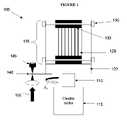
- a shutter assembly 100constructed according to the disclosed principles for use with a laser-produced plasma (LPP) device.
- the assembly 100is included in the vacuum chamber of the LPP device (see FIG. 2 ) to reduce or eliminate debris produced by the radiation generating process from exiting the vacuum chamber with the generated X-rays.
- LPPlaser-produced plasma
- the assembly 100includes a shutter 105 mounted on a rotating shaft 110 , which is connected to a motor 115 .
- the motor 115 and shaft 110are used to rotate the shutter 105 (as indicated by arrow A 1 ) at a precise angular velocity selected to allow X-rays or other short-wavelength radiation to pass through the shutter 105 , but block most or all of the unwanted debris from passing through the shutter 105 .
- the shutter 105includes a base 120 and a plurality of openings or apertures 125 created between multiple vanes or blades. The blades are held together and precisely spaced using spacers 130 placed between the blades and held together using fasteners, such as bolts 135 .
- the vanesmay be constructed of metal for durability; however, in other embodiments the vanes may be constructed of plastic or other material.
- construction techniques for the vanes/shuttercan include cutting the component from a solid material, such as with an EDM device; however, even manufacturing technique may be employed.
- the shutter 105reduces or eliminates the amount of debris created through the laser irradiation process used to generate X-rays in the LPP device by timing the alignment of the apertures 125 with the X-rays to be collected at the output of the vacuum chamber.
- a laseris used to irradiate a target, such as copper tape
- X-raysare generated from the plasma created by the irradiation of the target.
- debris from the irradiated target in the form of projectile or ballistic particlesis also generated at the radiation source.
- the rotation of the shutter 105is timed so that the X-rays will pass through the apertures 125 in the shutter 105 at the desired time. But the rotation of the shutter 105 is also timed so that after the X-rays pass through the apertures 125 , the shutter 105 turns to obstruct the ballistic debris traveling in the same or similar direction as the collected X-rays. Thus, this debris impacts the blades of the shutter 105 and most if not all of it cannot reach the output of the chamber where the X-rays were collected.
- a synchronization device having a blade 140is formed on the rotating base 120 .
- a photodetector 145receives a light or laser beam 150 , and the blade 140 interrupts the beam 150 at a given point during the rotation of the shutter 105 .
- the firing of the laser generator that irradiates the target material to create the X-rays (and the resulting debris)can be timed by when the blade 140 interrupts the beam 150 .
- this timing adjustmentalso takes into account the speed of the X-rays and the debris, as well as the rotational velocity of the rotating shutter 105 and its distance from the radiation source. A more detailed example having such parameters is discussed with reference to FIG. 2 .
- FIG. 2illustrates a plan view of a vacuum chamber 200 of an LPP device, which provides an environment for implementing a rotational mechanical shutter as disclosed herein.
- the embodiment in FIG. 2also illustrates a different embodiment of a rotational shutter 205 constructed in accordance with the disclosed principles.
- the shutter 205has a square shape and still includes apertures 210 created by the spacing of a plurality of blades.
- the shutter 205is configured to rotate (shown by arrow A 1 ) on a shaft in order to align the apertures 210 with the output 215 of the vacuum chamber 200 at only desired times.
- a laser 220is generated from a source external to the vacuum chamber 200 . That laser 220 is then directed and focused to precisely impact a target (not illustrated) to generate a radiation source 225 .
- the radiation source 225 created by the irradiation processforms a plasma that generates X-rays 230 , as well as debris 235 .
- the debris 235typically consists of particles of the target that have been ablated during the irradiation process.
- the rotation of the shutter 210is timed with the irradiation process such that the desired X-rays 230 are allowed to pass through the apertures 210 of the shutter 205 to the output 215 of the chamber 200 to be collected and harnessed as needed.
- the rotation of the shutter 205is also timed so that the apertures 210 no longer provide a line-of-sight between the radiation source 225 and the output 215 of the vacuum chamber 200 by the time that the debris 235 reaches the shutter.
- debris 235 with the same or similar trajectory as the X-rays 230will not be permitted to pass through the shutter 205 to the output 215 .
- most or all of this debris 235will be prevented from exiting the chamber 200 at the point where the X-rays 230 are collected.
- the vanes or blades of the shutter 205further work to brush or knock away debris 235 that may be lingering near the shutter 205 after its prior rotation obstructed the line-of-sight to the output 215 .
- the shutter 205is again constructed in the shape of a square and, in this example, has dimensions of approximately 2 cm on all sides. Of course, other sizes and shapes for a shutter constructed as disclosed herein may be utilized. Moreover, in the illustrated embodiment of FIG. 2 , the shutter 205 is located 200 cm from the radiation source 225 . By taking into account these dimensions, as well as other parameters of the X-ray generation process, the precise rotation of the shutter 205 needed to perform as disclosed herein can be easily calculated. For example, if a source laser 220 and target are selected such that X-rays 230 of about 5 mrad are generated, the X-rays 230 are transmitted at the speed of light (3.0 ⁇ 10 10 cm/sec).
- the rotation of this embodiment of the shutter 205may be calculated to be about 0.06 radians in 2 ms.
- the shutter 205should be rotated at about 5 Hz, or 300 rpm. With these parameters, the shutter 205 should be capable of blocking about 90% of debris 235 traveling at this velocity at the outer edges of the shutter 205 , while blocking about 100% of such debris 235 at the center of the shutter 205 .
- the rotational speed of the shutter 205can be adjusted. For example, for debris traveling at a velocity of 10 6 cm/sec, it is determined that the rotation of the shutter 205 should be about 3000 rpm, rather than the previous 300 rpm. Of course, as the rotation of the shutter 205 is adjusted, so too can the timing of the firing of the source laser beam 220 used in the ablation process be adjusted to work in tandem with the debris shutter 205 .
- FIGS. 3A and 3Billustrated is another embodiment of a shutter assembly 300 constructed according to the disclosed principles.
- This embodimentprovides a “wheel” type shutter 305 that differs from the embodiments discussed above with reference to FIGS. 1 and 2 .
- the shutter 305is again mounted on a rotating shaft 310 at the center of the shutter 305 .
- the shaft 310is coupled to an encoded motor 315 that is configured to rotate the shutter 305 at the precise, needed velocity. More specifically, rather than including the blade and photodetector used in the embodiment of FIG. 2 for synchronizing the laser ablation process with the rotation of the shutter, the encoded motor 315 may be employed to provide such alignment and timing.
- a laser 320is fired at a target to generate a radiation source, as discussed above.
- the generated X-rays 325travel from the radiation source to the exit or output 335 of the chamber.
- the shutter 305is rotated so that the X-rays 325 are permitted to travel through rotating openings or apertures 330 in the shutter 305 to the output 335 of the chamber.
- This embodiment of the shutter 305includes apertures 330 that are radially arranged within the shutter 305 , and extend through its center. With this arrangement, as the shutter 305 rotates about its center, the apertures 330 provide a line-of-sight between the radiation source and the output 335 of the vacuum chamber.
- any number of apertures 330may be included in the shutter 305 .
- the rotation of the shutter 305 , and consequently the alignment of the apertures 330 with the path of the X-rays and blocking of debris,may then be adjusted to account for the change in the number apertures 330 provided in the shutter 305 .
Landscapes
- Life Sciences & Earth Sciences (AREA)
- Atmospheric Sciences (AREA)
- Health & Medical Sciences (AREA)
- Epidemiology (AREA)
- Public Health (AREA)
- Engineering & Computer Science (AREA)
- Environmental & Geological Engineering (AREA)
- Physics & Mathematics (AREA)
- General Physics & Mathematics (AREA)
- Exposure And Positioning Against Photoresist Photosensitive Materials (AREA)
Abstract
Description
Claims (17)
Priority Applications (1)
| Application Number | Priority Date | Filing Date | Title |
|---|---|---|---|
| US11/161,237US7302043B2 (en) | 2004-07-27 | 2005-07-27 | Rotating shutter for laser-produced plasma debris mitigation |
Applications Claiming Priority (2)
| Application Number | Priority Date | Filing Date | Title |
|---|---|---|---|
| US59141004P | 2004-07-27 | 2004-07-27 | |
| US11/161,237US7302043B2 (en) | 2004-07-27 | 2005-07-27 | Rotating shutter for laser-produced plasma debris mitigation |
Publications (2)
| Publication Number | Publication Date |
|---|---|
| US20060067476A1 US20060067476A1 (en) | 2006-03-30 |
| US7302043B2true US7302043B2 (en) | 2007-11-27 |
Family
ID=36099089
Family Applications (1)
| Application Number | Title | Priority Date | Filing Date |
|---|---|---|---|
| US11/161,237Expired - LifetimeUS7302043B2 (en) | 2004-07-27 | 2005-07-27 | Rotating shutter for laser-produced plasma debris mitigation |
Country Status (1)
| Country | Link |
|---|---|
| US (1) | US7302043B2 (en) |
Cited By (8)
| Publication number | Priority date | Publication date | Assignee | Title |
|---|---|---|---|---|
| US20070085044A1 (en)* | 2005-06-27 | 2007-04-19 | Xtreme Technologies Gmbh | Arrangement and method for the generation of extreme ultraviolet radiation |
| US20130120559A1 (en)* | 2011-10-27 | 2013-05-16 | Lawrence Livermore National Security, Llc | Method and system for inspecting surfaces of miniature components |
| WO2014113100A3 (en)* | 2012-10-26 | 2014-10-02 | Lawrence Livermore National Security, Llc | Irradiation shutter for target injection into a fusion chamber |
| US9216475B2 (en) | 2012-03-31 | 2015-12-22 | Fei Company | System for protecting light optical components during laser ablation |
| DE102015211427A1 (en) | 2014-07-07 | 2016-01-07 | Media Lario S.R.L. | Systems and methods for the synchronous operation of debris mitigation or Verschmutzungsabweisevorrichtungen |
| RU2726316C1 (en)* | 2020-01-25 | 2020-07-13 | Общество С Ограниченной Ответственностью "Эуф Лабс" | High-brightness source of short-wave radiation based on laser plasma |
| WO2020216950A1 (en) | 2019-04-26 | 2020-10-29 | Isteq B.V. | High brightness laser-produced plasma light source |
| RU2743572C1 (en)* | 2020-09-04 | 2021-02-20 | Общество С Ограниченной Ответственностью "Эуф Лабс" | High-brightness source of short-wave radiation (options) |
Families Citing this family (9)
| Publication number | Priority date | Publication date | Assignee | Title |
|---|---|---|---|---|
| US7889312B2 (en)* | 2006-09-22 | 2011-02-15 | Asml Netherlands B.V. | Apparatus comprising a rotating contaminant trap |
| ATE526612T1 (en)* | 2008-02-28 | 2011-10-15 | Koninkl Philips Electronics Nv | DEPOSIT REDUCTION DEVICE WITH ROTATABLE FILM TRAP |
| JP5683902B2 (en) | 2010-10-29 | 2015-03-11 | 株式会社東芝 | Laser ion source |
| CN102222534B (en)* | 2011-03-10 | 2013-06-12 | 中国原子能科学研究院 | A Beam Shutter Used in Ground Accelerator Simulation Test of Single Event Effect |
| DE102011089779B4 (en)* | 2011-12-23 | 2019-09-05 | Carl Zeiss Smt Gmbh | Device for suppressing foreign body components entrained with a light bundle along a beam path |
| NL2010965A (en)* | 2012-06-22 | 2013-12-24 | Asml Netherlands Bv | Radiation source and lithographic apparatus. |
| RU2701462C1 (en)* | 2018-11-26 | 2019-09-26 | Российская Федерация, от имени которой выступает Федеральное агентство по техническому регулированию и метрологии (Росстандарт) | Atomic beam interrupter |
| EP4209120A4 (en)* | 2020-09-04 | 2024-08-28 | Isteq B.V. | SHORT WAVELENGTH RADIATION SOURCE WITH MULTI-SECTION COLLECTOR MODULE |
| CN115915568A (en)* | 2022-12-02 | 2023-04-04 | 中国原子能科学研究院 | A beam blocking device for cyclotron single event effect ground test |
Citations (95)
| Publication number | Priority date | Publication date | Assignee | Title |
|---|---|---|---|---|
| US3647984A (en) | 1968-07-04 | 1972-03-07 | Sony Corp | Magnetic recording and/or reproducing device with tape engagement means which moves in a concentric path with the head |
| US3723246A (en) | 1971-05-27 | 1973-03-27 | Atomic Energy Commission | Plasma production apparatus having droplet production means and laserpre-pulse means |
| US3723703A (en) | 1971-02-08 | 1973-03-27 | Atomic Energy Commission | Laser energized plasma source |
| US3907477A (en) | 1974-02-26 | 1975-09-23 | Us Energy | Apparatus for producing laser targets |
| US4205278A (en) | 1978-01-11 | 1980-05-27 | The United States Of America As Represented By The United States Department Of Energy | Multiple excitation regenerative amplifier inertial confinement system |
| US4266506A (en) | 1978-01-25 | 1981-05-12 | The United States Of America As Represented By The United States Department Of Energy | Apparatus for producing cryogenic inertially driven fusion targets |
| US4317036A (en) | 1980-03-11 | 1982-02-23 | Wang Chia Gee | Scanning X-ray microscope |
| US4344911A (en) | 1977-11-14 | 1982-08-17 | The United States Of America As Represented By The United States Department Of Energy | Fluidized wall for protecting fusion chamber walls |
| US4376752A (en) | 1975-09-02 | 1983-03-15 | The United States Of America As Represented By The United States Department Of Energy | Foam encapsulated targets |
| US4432933A (en) | 1973-03-09 | 1984-02-21 | Kms Fusion, Inc. | Process for the fabrication of thermonuclear fuel pellets and the product thereof |
| US4463413A (en) | 1983-08-29 | 1984-07-31 | Shirley Howard L | Adjustable photographic light stand |
| US4608222A (en) | 1971-01-29 | 1986-08-26 | Kms Fusion, Inc. | Method of achieving the controlled release of thermonuclear energy |
| US4630275A (en) | 1984-12-10 | 1986-12-16 | Allied Corporation | Controlled slow Q-switch |
| US4646308A (en) | 1985-09-30 | 1987-02-24 | Spectra-Physics, Inc. | Synchronously pumped dye laser using ultrashort pump pulses |
| US4687618A (en) | 1975-09-02 | 1987-08-18 | The United States Of America As Represented By The United States Department Of Energy | Laser-fusion targets for reactors |
| US4723262A (en) | 1984-12-26 | 1988-02-02 | Kabushiki Kaisha Toshiba | Apparatus for producing soft X-rays using a high energy laser beam |
| US4735762A (en) | 1983-09-29 | 1988-04-05 | The United States Of America As Represented By The United States Department Of Energy | Laser or charged-particle-beam fusion reactor with direct electric generation by magnetic flux compression |
| US4767826A (en) | 1985-07-18 | 1988-08-30 | Polytechnic Institute Of New York | Radiation-sensitive polymers |
| US4853191A (en) | 1987-03-01 | 1989-08-01 | Bayer Do Brasil S.A. | Process for the removal of sulfur-containing gases |
| US4870674A (en) | 1986-12-12 | 1989-09-26 | Carl-Zeiss-Stiftung | X-ray microscope |
| US4896341A (en) | 1984-11-08 | 1990-01-23 | Hampshire Instruments, Inc. | Long life X-ray source target |
| US4930901A (en) | 1988-12-23 | 1990-06-05 | Electro Scientific Industries, Inc. | Method of and apparatus for modulating a laser beam |
| US4939715A (en) | 1987-12-29 | 1990-07-03 | Minnesota Mining And Manufacturing Company | Tape scanning apparatus |
| US4979203A (en) | 1989-06-19 | 1990-12-18 | Princeton X-Ray Laser | X-ray laser microscope apparatus |
| US5003543A (en) | 1990-01-19 | 1991-03-26 | California Jamar, Incorporated | Laser plasma X-ray source |
| US5006184A (en) | 1988-11-05 | 1991-04-09 | Pelikan Aktiengesellschaft | Hand operated device for transferring a film from a carrier tape to a substrate |
| US5021628A (en) | 1970-11-30 | 1991-06-04 | Lemelson Jerome H | Apparatus and method for reacting on matter |
| US5043131A (en) | 1989-12-18 | 1991-08-27 | Kms Fusion, Inc. | Ignition of deuterium-trtium fuel targets |
| US5052034A (en) | 1989-10-30 | 1991-09-24 | Siemens Aktiengesellschaft | X-ray generator |
| US5081635A (en) | 1987-08-25 | 1992-01-14 | Kabushiki Kaisha Komatsu Seisakusho | Apparatus for controlling output from an excimer laser device |
| US5107526A (en) | 1990-10-31 | 1992-04-21 | The United State Of America As Represented By The Administrator Of The National Aeronautics And Space Administration | Water window imaging x-ray microscope |
| US5122506A (en) | 1989-08-10 | 1992-06-16 | Howard J. Greenwald | Contactless mass moving system |
| US5131023A (en) | 1990-03-01 | 1992-07-14 | Olympus Optical Co., Ltd. | Imaging type x-ray microscope apparatus with Schwarzschild optical system |
| US5132994A (en) | 1989-10-20 | 1992-07-21 | Olympus Optical Co., Ltd. | X-ray microscope |
| US5131957A (en) | 1990-01-11 | 1992-07-21 | Battelle Memorial Institute | Material properties |
| US5140600A (en) | 1990-11-28 | 1992-08-18 | Lambda Physik Gesellschaft Zur Herstellung Von Lasern Mbh | Method of controlling the total energy amount of a plurality of laser pulses |
| US5157684A (en) | 1991-10-23 | 1992-10-20 | United Technologies Corporation | Optically pulsed laser |
| US5177774A (en) | 1991-08-23 | 1993-01-05 | Trustees Of Princeton University | Reflection soft X-ray microscope and method |
| US5204887A (en) | 1990-06-01 | 1993-04-20 | Canon Kabushiki Kaisha | X-ray microscope |
| US5216699A (en) | 1991-09-17 | 1993-06-01 | Olympus Optical Co., Ltd. | X-ray microscope |
| US5222113A (en) | 1990-08-29 | 1993-06-22 | Carl-Zeiss-Stiftung | X-ray microscope |
| US5235606A (en) | 1991-10-29 | 1993-08-10 | University Of Michigan | Amplification of ultrashort pulses with nd:glass amplifiers pumped by alexandrite free running laser |
| US5311565A (en) | 1991-05-31 | 1994-05-10 | Olympus Optical Co., Ltd. | Soft X-ray microscope |
| US5315113A (en) | 1992-09-29 | 1994-05-24 | The Perkin-Elmer Corporation | Scanning and high resolution x-ray photoelectron spectroscopy and imaging |
| US5339323A (en) | 1993-04-30 | 1994-08-16 | Lumonics Corporation | Laser system for controlling emitted pulse energy |
| US5351279A (en) | 1992-08-28 | 1994-09-27 | Csl Opto-Electronics Corporation | X-ray microscope with a direct conversion type x-ray photocathode |
| WO1994026080A1 (en) | 1993-04-30 | 1994-11-10 | Council For The Central Laboratory Of The Researchcouncils | Laser-excited x-ray source |
| US5434875A (en) | 1994-08-24 | 1995-07-18 | Tamar Technology Co. | Low cost, high average power, high brightness solid state laser |
| US5434901A (en) | 1992-12-07 | 1995-07-18 | Olympus Optical Co., Ltd. | Soft X-ray microscope |
| US5450463A (en) | 1992-12-25 | 1995-09-12 | Olympus Optical Co., Ltd. | X-ray microscope |
| US5459771A (en) | 1994-04-01 | 1995-10-17 | University Of Central Florida | Water laser plasma x-ray point source and apparatus |
| US5487094A (en) | 1993-09-30 | 1996-01-23 | The Director-General Of The National Institute For Fusion Science | Double-layer pellet, method of manufacturing the same, and apparatus for manufacturing the same |
| US5491707A (en) | 1994-08-24 | 1996-02-13 | Jamar Technologies Co. | Low cost, high average power, high brightness solid state laser |
| US5539764A (en) | 1994-08-24 | 1996-07-23 | Jamar Technologies Co. | Laser generated X-ray source |
| US5544133A (en) | 1991-10-23 | 1996-08-06 | Samsung Electronics Co., Ltd. | Recording/reproducing apparatus using optical magnetic tape |
| US5550887A (en) | 1993-09-15 | 1996-08-27 | Carl-Zeiss-Stiftung | Phase contrast X-ray microscope |
| US5577091A (en) | 1994-04-01 | 1996-11-19 | University Of Central Florida | Water laser plasma x-ray point sources |
| US5668848A (en) | 1996-01-16 | 1997-09-16 | Jamar Technology Co | X-ray target tape system |
| US5680018A (en) | 1994-11-16 | 1997-10-21 | Research Development Corporation Of Japan | Method and apparatus for generating radiation |
| US5680429A (en) | 1995-01-18 | 1997-10-21 | Shimadzu Corporation | X-ray generating apparatus and X-ray microscope |
| US5742634A (en) | 1994-08-24 | 1998-04-21 | Imar Technology Co. | Picosecond laser |
| US5790627A (en) | 1995-09-20 | 1998-08-04 | Research Development Corp. | Method and apparatus for observing a specimen using an X-ray microscope |
| US5790574A (en) | 1994-08-24 | 1998-08-04 | Imar Technology Company | Low cost, high average power, high brightness solid state laser |
| US5832052A (en) | 1995-06-26 | 1998-11-03 | Shimadzu Corporation | X-ray microscope |
| US5864599A (en) | 1996-04-26 | 1999-01-26 | Cowan Paul Lloyd | X-ray moire microscope |
| US5991360A (en) | 1997-02-07 | 1999-11-23 | Hitachi, Ltd. | Laser plasma x-ray source, semiconductor lithography apparatus using the same and a method thereof |
| US6002744A (en) | 1996-04-25 | 1999-12-14 | Jettec Ab | Method and apparatus for generating X-ray or EUV radiation |
| US6016324A (en) | 1994-08-24 | 2000-01-18 | Jmar Research, Inc. | Short pulse laser system |
| US6167112A (en) | 1996-01-12 | 2000-12-26 | Bastian Nieman | X-ray microscope with zone plates |
| US6188746B1 (en) | 1996-11-01 | 2001-02-13 | The Board Of Trustees Of University Of Illinois | Spherical inertial electrostatic confinement device as a tunable x-ray source |
| WO2001031678A1 (en) | 1999-10-27 | 2001-05-03 | Jmar Research, Inc. | Method and radiation generating system using microtargets |
| US6275565B1 (en) | 1999-03-31 | 2001-08-14 | Agency Of Industrial Science And Technology | Laser plasma light source and method of generating radiation using the same |
| US6304630B1 (en) | 1999-12-24 | 2001-10-16 | U.S. Philips Corporation | Method of generating EUV radiation, method of manufacturing a device by means of said radiation, EUV radiation source unit, and lithographic projection apparatus provided with such a radiation source unit |
| US6307913B1 (en) | 1998-10-27 | 2001-10-23 | Jmar Research, Inc. | Shaped source of soft x-ray, extreme ultraviolet and ultraviolet radiation |
| US20020018288A1 (en) | 1999-10-15 | 2002-02-14 | Jmar Research, Inc. | High intensity and high power solid state laser amplifying system and method |
| US20020034879A1 (en) | 2000-08-11 | 2002-03-21 | The Regents Of The University Of California | Method for nanomachining high aspect ratio structures |
| US6377651B1 (en) | 1999-10-11 | 2002-04-23 | University Of Central Florida | Laser plasma source for extreme ultraviolet lithography using a water droplet target |
| US6389101B1 (en) | 1999-05-24 | 2002-05-14 | Jmar Research, Inc. | Parallel x-ray nanotomography |
| US20020070353A1 (en) | 2000-10-20 | 2002-06-13 | Martin Richardson | EUV, XUV, and X-Ray wavelength sources created from laser plasma produced from liquid metal solutions |
| US6418177B1 (en) | 1984-08-09 | 2002-07-09 | John E Stauffer | Fuel pellets for thermonuclear reactions |
| US6472295B1 (en) | 1999-08-27 | 2002-10-29 | Jmar Research, Inc. | Method and apparatus for laser ablation of a target material |
| US20020191746A1 (en) | 2001-06-19 | 2002-12-19 | Mark Dinsmore | X-ray source for materials analysis systems |
| US6507641B1 (en) | 1999-10-08 | 2003-01-14 | Nikon Corporation | X-ray-generation devices, X-ray microlithography apparatus comprising same, and microelectronic-device fabrication methods utilizing same |
| US20030010791A1 (en) | 2001-07-13 | 2003-01-16 | Andrew Gentiluomo | Method and apparatus for dispensing a customized pharamaceutical mixture |
| US6522717B1 (en) | 1999-08-11 | 2003-02-18 | Nikon Corporation | Reflective-type soft x-ray microscope |
| US6624431B1 (en) | 1999-07-21 | 2003-09-23 | Jmar Research, Inc. | High collection angle short wavelength radiation collimator and focusing optic |
| US20030210717A1 (en) | 2002-05-08 | 2003-11-13 | Harry Rieger | Method and system for providing a pulse laser |
| US6720556B2 (en) | 2000-07-06 | 2004-04-13 | Yeda Research And Development Co. Ltd. | Electron spectroscopy employing controlled surface charging |
| US20040108473A1 (en) | 2000-06-09 | 2004-06-10 | Melnychuk Stephan T. | Extreme ultraviolet light source |
| US20040171017A1 (en) | 2001-07-02 | 2004-09-02 | Giuseppe Firrao | Method to distribute liquids containing molecules in solution and to deposit said molecules on solid supports, and relative device |
| US20040196883A1 (en) | 2003-04-03 | 2004-10-07 | Jmar Research Inc. | Diode-pumped solid state laser system utilizing high power diode bars |
| US20040200977A1 (en) | 2003-01-02 | 2004-10-14 | Jmar Research Inc. | Method and apparatus for generating a membrane target for laser produced plasma |
| US20040238762A1 (en) | 2002-04-05 | 2004-12-02 | Haraku Mizoguchi | Extreme ultraviolet light source |
| US6867843B2 (en)* | 2001-07-05 | 2005-03-15 | Canon Kabushiki Kaisha | Debris removing system for use in X-ray light source |
| US7057190B2 (en)* | 2002-08-23 | 2006-06-06 | Asml Netherlands B.V. | Lithographic projection apparatus, particle barrier for use therein, integrated structure manufacturing method, and device manufactured thereby |
- 2005
- 2005-07-27USUS11/161,237patent/US7302043B2/ennot_activeExpired - Lifetime
Patent Citations (103)
| Publication number | Priority date | Publication date | Assignee | Title |
|---|---|---|---|---|
| US3647984A (en) | 1968-07-04 | 1972-03-07 | Sony Corp | Magnetic recording and/or reproducing device with tape engagement means which moves in a concentric path with the head |
| US5021628A (en) | 1970-11-30 | 1991-06-04 | Lemelson Jerome H | Apparatus and method for reacting on matter |
| US4608222A (en) | 1971-01-29 | 1986-08-26 | Kms Fusion, Inc. | Method of achieving the controlled release of thermonuclear energy |
| US3723703A (en) | 1971-02-08 | 1973-03-27 | Atomic Energy Commission | Laser energized plasma source |
| US3723246A (en) | 1971-05-27 | 1973-03-27 | Atomic Energy Commission | Plasma production apparatus having droplet production means and laserpre-pulse means |
| US4432933A (en) | 1973-03-09 | 1984-02-21 | Kms Fusion, Inc. | Process for the fabrication of thermonuclear fuel pellets and the product thereof |
| US3907477A (en) | 1974-02-26 | 1975-09-23 | Us Energy | Apparatus for producing laser targets |
| US4376752A (en) | 1975-09-02 | 1983-03-15 | The United States Of America As Represented By The United States Department Of Energy | Foam encapsulated targets |
| US4687618A (en) | 1975-09-02 | 1987-08-18 | The United States Of America As Represented By The United States Department Of Energy | Laser-fusion targets for reactors |
| US4344911A (en) | 1977-11-14 | 1982-08-17 | The United States Of America As Represented By The United States Department Of Energy | Fluidized wall for protecting fusion chamber walls |
| US4205278A (en) | 1978-01-11 | 1980-05-27 | The United States Of America As Represented By The United States Department Of Energy | Multiple excitation regenerative amplifier inertial confinement system |
| US4266506A (en) | 1978-01-25 | 1981-05-12 | The United States Of America As Represented By The United States Department Of Energy | Apparatus for producing cryogenic inertially driven fusion targets |
| US4317036A (en) | 1980-03-11 | 1982-02-23 | Wang Chia Gee | Scanning X-ray microscope |
| US4463413A (en) | 1983-08-29 | 1984-07-31 | Shirley Howard L | Adjustable photographic light stand |
| US4735762A (en) | 1983-09-29 | 1988-04-05 | The United States Of America As Represented By The United States Department Of Energy | Laser or charged-particle-beam fusion reactor with direct electric generation by magnetic flux compression |
| US6418177B1 (en) | 1984-08-09 | 2002-07-09 | John E Stauffer | Fuel pellets for thermonuclear reactions |
| US4896341A (en) | 1984-11-08 | 1990-01-23 | Hampshire Instruments, Inc. | Long life X-ray source target |
| US4630275A (en) | 1984-12-10 | 1986-12-16 | Allied Corporation | Controlled slow Q-switch |
| US4723262A (en) | 1984-12-26 | 1988-02-02 | Kabushiki Kaisha Toshiba | Apparatus for producing soft X-rays using a high energy laser beam |
| US4767826A (en) | 1985-07-18 | 1988-08-30 | Polytechnic Institute Of New York | Radiation-sensitive polymers |
| US4646308A (en) | 1985-09-30 | 1987-02-24 | Spectra-Physics, Inc. | Synchronously pumped dye laser using ultrashort pump pulses |
| US4870674A (en) | 1986-12-12 | 1989-09-26 | Carl-Zeiss-Stiftung | X-ray microscope |
| US4853191A (en) | 1987-03-01 | 1989-08-01 | Bayer Do Brasil S.A. | Process for the removal of sulfur-containing gases |
| US5081635A (en) | 1987-08-25 | 1992-01-14 | Kabushiki Kaisha Komatsu Seisakusho | Apparatus for controlling output from an excimer laser device |
| US4939715A (en) | 1987-12-29 | 1990-07-03 | Minnesota Mining And Manufacturing Company | Tape scanning apparatus |
| US5006184A (en) | 1988-11-05 | 1991-04-09 | Pelikan Aktiengesellschaft | Hand operated device for transferring a film from a carrier tape to a substrate |
| US4930901A (en) | 1988-12-23 | 1990-06-05 | Electro Scientific Industries, Inc. | Method of and apparatus for modulating a laser beam |
| US4979203A (en) | 1989-06-19 | 1990-12-18 | Princeton X-Ray Laser | X-ray laser microscope apparatus |
| US5122506A (en) | 1989-08-10 | 1992-06-16 | Howard J. Greenwald | Contactless mass moving system |
| US5132994A (en) | 1989-10-20 | 1992-07-21 | Olympus Optical Co., Ltd. | X-ray microscope |
| US5052034A (en) | 1989-10-30 | 1991-09-24 | Siemens Aktiengesellschaft | X-ray generator |
| US5043131A (en) | 1989-12-18 | 1991-08-27 | Kms Fusion, Inc. | Ignition of deuterium-trtium fuel targets |
| US5131957A (en) | 1990-01-11 | 1992-07-21 | Battelle Memorial Institute | Material properties |
| US5003543A (en) | 1990-01-19 | 1991-03-26 | California Jamar, Incorporated | Laser plasma X-ray source |
| US5131023A (en) | 1990-03-01 | 1992-07-14 | Olympus Optical Co., Ltd. | Imaging type x-ray microscope apparatus with Schwarzschild optical system |
| US5204887A (en) | 1990-06-01 | 1993-04-20 | Canon Kabushiki Kaisha | X-ray microscope |
| US5222113A (en) | 1990-08-29 | 1993-06-22 | Carl-Zeiss-Stiftung | X-ray microscope |
| US5107526A (en) | 1990-10-31 | 1992-04-21 | The United State Of America As Represented By The Administrator Of The National Aeronautics And Space Administration | Water window imaging x-ray microscope |
| US5140600A (en) | 1990-11-28 | 1992-08-18 | Lambda Physik Gesellschaft Zur Herstellung Von Lasern Mbh | Method of controlling the total energy amount of a plurality of laser pulses |
| US5311565A (en) | 1991-05-31 | 1994-05-10 | Olympus Optical Co., Ltd. | Soft X-ray microscope |
| US5177774A (en) | 1991-08-23 | 1993-01-05 | Trustees Of Princeton University | Reflection soft X-ray microscope and method |
| US5216699A (en) | 1991-09-17 | 1993-06-01 | Olympus Optical Co., Ltd. | X-ray microscope |
| US5544133A (en) | 1991-10-23 | 1996-08-06 | Samsung Electronics Co., Ltd. | Recording/reproducing apparatus using optical magnetic tape |
| US5157684A (en) | 1991-10-23 | 1992-10-20 | United Technologies Corporation | Optically pulsed laser |
| US5235606A (en) | 1991-10-29 | 1993-08-10 | University Of Michigan | Amplification of ultrashort pulses with nd:glass amplifiers pumped by alexandrite free running laser |
| US5351279A (en) | 1992-08-28 | 1994-09-27 | Csl Opto-Electronics Corporation | X-ray microscope with a direct conversion type x-ray photocathode |
| US5315113A (en) | 1992-09-29 | 1994-05-24 | The Perkin-Elmer Corporation | Scanning and high resolution x-ray photoelectron spectroscopy and imaging |
| US5434901A (en) | 1992-12-07 | 1995-07-18 | Olympus Optical Co., Ltd. | Soft X-ray microscope |
| US5450463A (en) | 1992-12-25 | 1995-09-12 | Olympus Optical Co., Ltd. | X-ray microscope |
| US5590168A (en) | 1992-12-25 | 1996-12-31 | Olympus Optical Co., Ltd. | X-ray microscope |
| WO1994026080A1 (en) | 1993-04-30 | 1994-11-10 | Council For The Central Laboratory Of The Researchcouncils | Laser-excited x-ray source |
| US5339323A (en) | 1993-04-30 | 1994-08-16 | Lumonics Corporation | Laser system for controlling emitted pulse energy |
| US5550887A (en) | 1993-09-15 | 1996-08-27 | Carl-Zeiss-Stiftung | Phase contrast X-ray microscope |
| US5487094A (en) | 1993-09-30 | 1996-01-23 | The Director-General Of The National Institute For Fusion Science | Double-layer pellet, method of manufacturing the same, and apparatus for manufacturing the same |
| US5577091A (en) | 1994-04-01 | 1996-11-19 | University Of Central Florida | Water laser plasma x-ray point sources |
| US5459771A (en) | 1994-04-01 | 1995-10-17 | University Of Central Florida | Water laser plasma x-ray point source and apparatus |
| US5434875A (en) | 1994-08-24 | 1995-07-18 | Tamar Technology Co. | Low cost, high average power, high brightness solid state laser |
| US5491707A (en) | 1994-08-24 | 1996-02-13 | Jamar Technologies Co. | Low cost, high average power, high brightness solid state laser |
| US5742634A (en) | 1994-08-24 | 1998-04-21 | Imar Technology Co. | Picosecond laser |
| US5539764A (en) | 1994-08-24 | 1996-07-23 | Jamar Technologies Co. | Laser generated X-ray source |
| US5790574A (en) | 1994-08-24 | 1998-08-04 | Imar Technology Company | Low cost, high average power, high brightness solid state laser |
| US6016324A (en) | 1994-08-24 | 2000-01-18 | Jmar Research, Inc. | Short pulse laser system |
| US5680018A (en) | 1994-11-16 | 1997-10-21 | Research Development Corporation Of Japan | Method and apparatus for generating radiation |
| US6157701A (en) | 1995-01-18 | 2000-12-05 | Shimadzu Corporation | X-ray generating apparatus and X-ray microscope |
| US5680429A (en) | 1995-01-18 | 1997-10-21 | Shimadzu Corporation | X-ray generating apparatus and X-ray microscope |
| US5832052A (en) | 1995-06-26 | 1998-11-03 | Shimadzu Corporation | X-ray microscope |
| US5790627A (en) | 1995-09-20 | 1998-08-04 | Research Development Corp. | Method and apparatus for observing a specimen using an X-ray microscope |
| US6167112A (en) | 1996-01-12 | 2000-12-26 | Bastian Nieman | X-ray microscope with zone plates |
| US5668848A (en) | 1996-01-16 | 1997-09-16 | Jamar Technology Co | X-ray target tape system |
| US6002744A (en) | 1996-04-25 | 1999-12-14 | Jettec Ab | Method and apparatus for generating X-ray or EUV radiation |
| US5864599A (en) | 1996-04-26 | 1999-01-26 | Cowan Paul Lloyd | X-ray moire microscope |
| US6188746B1 (en) | 1996-11-01 | 2001-02-13 | The Board Of Trustees Of University Of Illinois | Spherical inertial electrostatic confinement device as a tunable x-ray source |
| US5991360A (en) | 1997-02-07 | 1999-11-23 | Hitachi, Ltd. | Laser plasma x-ray source, semiconductor lithography apparatus using the same and a method thereof |
| US6307913B1 (en) | 1998-10-27 | 2001-10-23 | Jmar Research, Inc. | Shaped source of soft x-ray, extreme ultraviolet and ultraviolet radiation |
| US6275565B1 (en) | 1999-03-31 | 2001-08-14 | Agency Of Industrial Science And Technology | Laser plasma light source and method of generating radiation using the same |
| US6389101B1 (en) | 1999-05-24 | 2002-05-14 | Jmar Research, Inc. | Parallel x-ray nanotomography |
| US6624431B1 (en) | 1999-07-21 | 2003-09-23 | Jmar Research, Inc. | High collection angle short wavelength radiation collimator and focusing optic |
| US6522717B1 (en) | 1999-08-11 | 2003-02-18 | Nikon Corporation | Reflective-type soft x-ray microscope |
| US6472295B1 (en) | 1999-08-27 | 2002-10-29 | Jmar Research, Inc. | Method and apparatus for laser ablation of a target material |
| US6507641B1 (en) | 1999-10-08 | 2003-01-14 | Nikon Corporation | X-ray-generation devices, X-ray microlithography apparatus comprising same, and microelectronic-device fabrication methods utilizing same |
| US6377651B1 (en) | 1999-10-11 | 2002-04-23 | University Of Central Florida | Laser plasma source for extreme ultraviolet lithography using a water droplet target |
| US20020018288A1 (en) | 1999-10-15 | 2002-02-14 | Jmar Research, Inc. | High intensity and high power solid state laser amplifying system and method |
| WO2001031678A1 (en) | 1999-10-27 | 2001-05-03 | Jmar Research, Inc. | Method and radiation generating system using microtargets |
| US6304630B1 (en) | 1999-12-24 | 2001-10-16 | U.S. Philips Corporation | Method of generating EUV radiation, method of manufacturing a device by means of said radiation, EUV radiation source unit, and lithographic projection apparatus provided with such a radiation source unit |
| US20040108473A1 (en) | 2000-06-09 | 2004-06-10 | Melnychuk Stephan T. | Extreme ultraviolet light source |
| US6720556B2 (en) | 2000-07-06 | 2004-04-13 | Yeda Research And Development Co. Ltd. | Electron spectroscopy employing controlled surface charging |
| US20020034879A1 (en) | 2000-08-11 | 2002-03-21 | The Regents Of The University Of California | Method for nanomachining high aspect ratio structures |
| US20040208286A1 (en) | 2000-10-20 | 2004-10-21 | University Of Central Florida | EUV, XUV, and X-ray wavelength sources created from laser plasma produced from liquid metal solutions |
| US6831963B2 (en) | 2000-10-20 | 2004-12-14 | University Of Central Florida | EUV, XUV, and X-Ray wavelength sources created from laser plasma produced from liquid metal solutions |
| US20020141536A1 (en) | 2000-10-20 | 2002-10-03 | Martin Richardson | EUV, XUV, and X-ray wavelength sources created from laser plasma produced from liquid metal solutions, and nano-size particles in solutions |
| US20040170252A1 (en) | 2000-10-20 | 2004-09-02 | University Of Central Florida | EUV, XUV, and X-Ray wavelength sources created from laser plasma produced from liquid metal solutions, and nano-size particles in solutions |
| US6865255B2 (en) | 2000-10-20 | 2005-03-08 | University Of Central Florida | EUV, XUV, and X-ray wavelength sources created from laser plasma produced from liquid metal solutions, and nano-size particles in solutions |
| US6862339B2 (en) | 2000-10-20 | 2005-03-01 | University Of Central Florida | EUV, XUV, and X-ray wavelength sources created from laser plasma produced from liquid metal solutions, and nano-size particles in solutions |
| US20020070353A1 (en) | 2000-10-20 | 2002-06-13 | Martin Richardson | EUV, XUV, and X-Ray wavelength sources created from laser plasma produced from liquid metal solutions |
| US20020191746A1 (en) | 2001-06-19 | 2002-12-19 | Mark Dinsmore | X-ray source for materials analysis systems |
| US20040171017A1 (en) | 2001-07-02 | 2004-09-02 | Giuseppe Firrao | Method to distribute liquids containing molecules in solution and to deposit said molecules on solid supports, and relative device |
| US6867843B2 (en)* | 2001-07-05 | 2005-03-15 | Canon Kabushiki Kaisha | Debris removing system for use in X-ray light source |
| US20030010791A1 (en) | 2001-07-13 | 2003-01-16 | Andrew Gentiluomo | Method and apparatus for dispensing a customized pharamaceutical mixture |
| US20040238762A1 (en) | 2002-04-05 | 2004-12-02 | Haraku Mizoguchi | Extreme ultraviolet light source |
| US20030210717A1 (en) | 2002-05-08 | 2003-11-13 | Harry Rieger | Method and system for providing a pulse laser |
| US7057190B2 (en)* | 2002-08-23 | 2006-06-06 | Asml Netherlands B.V. | Lithographic projection apparatus, particle barrier for use therein, integrated structure manufacturing method, and device manufactured thereby |
| US20040200977A1 (en) | 2003-01-02 | 2004-10-14 | Jmar Research Inc. | Method and apparatus for generating a membrane target for laser produced plasma |
| US20040196883A1 (en) | 2003-04-03 | 2004-10-07 | Jmar Research Inc. | Diode-pumped solid state laser system utilizing high power diode bars |
Non-Patent Citations (3)
| Title |
|---|
| "Nanomachining of High Aspect Ratio Structures", Technology Transfer www.lbl.gov/Tech-Transfer/techs/lbnll498.html. |
| International Search Report of PCT Application No. PCT/US03/41694 issued Nov. 16, 2004. |
| L. Rymell, H.M. Hertz; Droplet target for low-debris laser-plasma soft X-ray generation; Optics Communications 103 (1993) 105-110. |
Cited By (10)
| Publication number | Priority date | Publication date | Assignee | Title |
|---|---|---|---|---|
| US20070085044A1 (en)* | 2005-06-27 | 2007-04-19 | Xtreme Technologies Gmbh | Arrangement and method for the generation of extreme ultraviolet radiation |
| US7531820B2 (en)* | 2005-06-27 | 2009-05-12 | Xtreme Technologies Gmbh | Arrangement and method for the generation of extreme ultraviolet radiation |
| US20130120559A1 (en)* | 2011-10-27 | 2013-05-16 | Lawrence Livermore National Security, Llc | Method and system for inspecting surfaces of miniature components |
| US9216475B2 (en) | 2012-03-31 | 2015-12-22 | Fei Company | System for protecting light optical components during laser ablation |
| WO2014113100A3 (en)* | 2012-10-26 | 2014-10-02 | Lawrence Livermore National Security, Llc | Irradiation shutter for target injection into a fusion chamber |
| DE102015211427A1 (en) | 2014-07-07 | 2016-01-07 | Media Lario S.R.L. | Systems and methods for the synchronous operation of debris mitigation or Verschmutzungsabweisevorrichtungen |
| US9609731B2 (en) | 2014-07-07 | 2017-03-28 | Media Lario Srl | Systems and methods for synchronous operation of debris-mitigation devices |
| WO2020216950A1 (en) | 2019-04-26 | 2020-10-29 | Isteq B.V. | High brightness laser-produced plasma light source |
| RU2726316C1 (en)* | 2020-01-25 | 2020-07-13 | Общество С Ограниченной Ответственностью "Эуф Лабс" | High-brightness source of short-wave radiation based on laser plasma |
| RU2743572C1 (en)* | 2020-09-04 | 2021-02-20 | Общество С Ограниченной Ответственностью "Эуф Лабс" | High-brightness source of short-wave radiation (options) |
Also Published As
| Publication number | Publication date |
|---|---|
| US20060067476A1 (en) | 2006-03-30 |
Similar Documents
| Publication | Publication Date | Title |
|---|---|---|
| US7302043B2 (en) | Rotating shutter for laser-produced plasma debris mitigation | |
| JP6860185B2 (en) | High-intensity LPP radiation source, radiation generation method, and debris reduction method | |
| US10887973B2 (en) | High brightness laser-produced plasma light source | |
| JP6793644B2 (en) | Plasma-based light source | |
| US6377651B1 (en) | Laser plasma source for extreme ultraviolet lithography using a water droplet target | |
| US4872189A (en) | Target structure for x-ray lithography system | |
| US20020090054A1 (en) | Apparatus and method for containing debris from laser plasma radiation sources | |
| JP5983594B2 (en) | Light source device | |
| US11252810B2 (en) | Short-wavelength radiation source with multisectional collector module and method of collecting radiation | |
| KR20240087651A (en) | High-brightness laser-generated plasma source and radiation generation and collection method | |
| US12028958B2 (en) | High-brightness laser produced plasma source and method of generation and collection radiation | |
| WO2023135322A1 (en) | Target material, high-brightness euv source and method for generating euv radiation | |
| JP7549313B2 (en) | Short-wavelength radiation source with multi-section collector module | |
| RU2743572C1 (en) | High-brightness source of short-wave radiation (options) | |
| RU2726316C1 (en) | High-brightness source of short-wave radiation based on laser plasma | |
| EP0342208B1 (en) | X-ray lithography system comprising a thin target | |
| CN118140598A (en) | High brightness laser plasma light source and method for generating and collecting radiation | |
| Schulz et al. | A study of the feasibility of x-ray microscopy with a laser-plasma source | |
| RU2789275C1 (en) | Target material, high-brightness euv source and 13.5 nm radiation generation method | |
| US12372886B2 (en) | Acoustic particle deflection in lithography tool | |
| HK40033098A (en) | High-brightness lpp source and methods for generating radiation and mitigating debris | |
| Peeters et al. | Analysis of micron size space debris impacts on materials: comparison of ground-based testing and in-flight results | |
| HK40060058A (en) | High brightness laser-produced plasma light source | |
| London | A Study of the Feasibility of X-Ray Microscopy |
Legal Events
| Date | Code | Title | Description |
|---|---|---|---|
| AS | Assignment | Owner name:JMAR RESEARCH, INC., CALIFORNIA Free format text:ASSIGNMENT OF ASSIGNORS INTEREST;ASSIGNORS:BLOOM, SCOTT H.;RIEGER, HARRY;ALWAN, JAMES J.;REEL/FRAME:016889/0775;SIGNING DATES FROM 20041105 TO 20041108 | |
| AS | Assignment | Owner name:LAURUS MASTER FUND, LTD., NEW YORK Free format text:GRANT OF SECURITY INTEREST IN PATENTS AND TRADEMARKS;ASSIGNOR:JMAR RESEARCH, INC. (F/K/A JAMAR TECHNOLOGY CO. AND F/K/A JMAR TECHNOLOGY CO., A DELAWARE CORPORATION);REEL/FRAME:019224/0176 Effective date:20070411 | |
| AS | Assignment | Owner name:GATAN INC., PENNSYLVANIA Free format text:ASSIGNMENT OF ASSIGNORS INTEREST;ASSIGNOR:JMAR RESEARCH, INC.;REEL/FRAME:019541/0617 Effective date:20070710 | |
| STCF | Information on status: patent grant | Free format text:PATENTED CASE | |
| AS | Assignment | Owner name:JMAR RESEARCH, LTD., CALIFORNIA Free format text:RELEASE BY SECURED PARTY;ASSIGNOR:LAURUS MASTER FUND, LTD.;REEL/FRAME:020462/0166 Effective date:20070924 | |
| FPAY | Fee payment | Year of fee payment:4 | |
| FPAY | Fee payment | Year of fee payment:8 | |
| MAFP | Maintenance fee payment | Free format text:PAYMENT OF MAINTENANCE FEE, 12TH YEAR, LARGE ENTITY (ORIGINAL EVENT CODE: M1553); ENTITY STATUS OF PATENT OWNER: LARGE ENTITY Year of fee payment:12 |